U.S. General Services Administration · PDF file• GSA BIM Guide 08 - Facility Management...
62
September 30, 2016 This version of the GSA Building Information Modeling (BIM) Guide 07 - Building Elements is identified as version 1.0. The guide elucidates different forms of building information and provides guidance for how such information should be created, modified, and maintained in order to allow it to be utilized by multiple downstream business processes, including (but not limited to) portfolio and prospectus planning, facility operations and maintenance, and space and asset management. GSA invites the public to submit feedback on this document, as it will continue to serve as the basis for further development, validation, and professional editing. GSA will continue to issue updated versions to address and incorporate on-going feedback in an open and collaborative process. GSA recently published a BIM Glossary that defines many of the terms used in the BIM Guide series. Users can access the BIM Glossary and download the following BIM Guides at http://www.gsa.gov/bim: • GSA BIM Guide 01 - 3D-4D-BIM Overview • GSA BIM Guide 02 - Spatial Program Validation • GSA BIM Guide 03 - 3D Laser Scanning • GSA BIM Guide 04 - 4D Phasing • GSA BIM Guide 05 - Energy Performance • GSA BIM Guide 08 - Facility Management Project teams are encouraged to review all available BIM Guides and apply them as appropriate. For further information about GSA’s National 3D-4D-BIM Program or to submit comments or questions, please visit http://www.gsa.gov/bim. The National 3D-4D BIM Program U.S. General Services Administration 1800 F Street NW Washington, DC 20405 U.S. General Services Administration
Transcript of U.S. General Services Administration · PDF file• GSA BIM Guide 08 - Facility Management...

September 30, 2016 This version of the GSA Building Information Modeling (BIM) Guide 07 - Building Elements is identified as version 1.0. The guide elucidates different forms of building information and provides guidance for how such information should be created, modified, and maintained in order to allow it to be utilized by multiple downstream business processes, including (but not limited to) portfolio and prospectus planning, facility operations and maintenance, and space and asset management. GSA invites the public to submit feedback on this document, as it will continue to serve as the basis for further development, validation, and professional editing. GSA will continue to issue updated versions to address and incorporate on-going feedback in an open and collaborative process. GSA recently published a BIM Glossary that defines many of the terms used in the BIM Guide series. Users can access the BIM Glossary and download the following BIM Guides at http://www.gsa.gov/bim: • GSA BIM Guide 01 - 3D-4D-BIM Overview• GSA BIM Guide 02 - Spatial Program Validation• GSA BIM Guide 03 - 3D Laser Scanning• GSA BIM Guide 04 - 4D Phasing• GSA BIM Guide 05 - Energy Performance• GSA BIM Guide 08 - Facility Management
Project teams are encouraged to review all available BIM Guides and apply them as appropriate. For further information about GSA’s National 3D-4D-BIM Program or to submit comments or questions, please visit http://www.gsa.gov/bim.
The National 3D-4D BIM ProgramU.S. General Services Administration1800 F Street NWWashington, DC 20405
U.S. General Services Administration

GSA BIM Guide 07www.gsa.gov/bim
GSA BIM Guide 07 Version 1.0 Practical Guidance for Modelers II
BIM Guide 07Building Elements
GSA BIM Guide 07www.gsa.gov/bim

GSA BIM Guide 07www.gsa.gov/bim
GSA Building Information Modeling Guide Series
GSA BIM Guide 07 – Building Elements
Version 1.0 – September 2016
United States General Services Administration (GSA)

GSA BIM Guide 07www.gsa.gov/bim
Table of Contents
Table of Contents . . . . . . . . . . . . . . . . . . . . . . . . . . . . . . . . . . . . . . . . . . . . . . . . . . . . . . . . . . . . . . . . . . . . . . . . . . . 1Foreword . . . . . . . . . . . . . . . . . . . . . . . . . . . . . . . . . . . . . . . . . . . . . . . . . . . . . . . . . . . . . . . . . . . . . . . . . . . . . . . . 31. Introduction . . . . . . . . . . . . . . . . . . . . . . . . . . . . . . . . . . . . . . . . . . . . . . . . . . . . . . . . . . . . . . . . . . . . . . . . . . . . 4
1.1 File Formats and Software Tools . . . . . . . . . . . . . . . . . . . . . . . . . . . . . . . . . . . . . . . . . . . . . . . . . . . . . . . . . . . . 52. Technical Guidance . . . . . . . . . . . . . . . . . . . . . . . . . . . . . . . . . . . . . . . . . . . . . . . . . . . . . . . . . . . . . . . . . . . . . . . . 6
2.1 Model Elements Overview . . . . . . . . . . . . . . . . . . . . . . . . . . . . . . . . . . . . . . . . . . . . . . . . . . . . . . . . . . . . . . . . 72.1.1 Model Ontology . . . . . . . . . . . . . . . . . . . . . . . . . . . . . . . . . . . . . . . . . . . . . . . . . . . . . . . . . . . . . . . . . . . 82.1.2 Levels of Detail and Levels of Development (LOD) . . . . . . . . . . . . . . . . . . . . . . . . . . . . . . . . . . . . . . . . . . 12
2.1.2.1 LOD 100 . . . . . . . . . . . . . . . . . . . . . . . . . . . . . . . . . . . . . . . . . . . . . . . . . . . . . . . . . . . . . . . . . . 132.1.2.2 LOD 200 . . . . . . . . . . . . . . . . . . . . . . . . . . . . . . . . . . . . . . . . . . . . . . . . . . . . . . . . . . . . . . . . . . 132.1.2.3 LOD 300 . . . . . . . . . . . . . . . . . . . . . . . . . . . . . . . . . . . . . . . . . . . . . . . . . . . . . . . . . . . . . . . . . . 132.1.2.4 LOD 350 . . . . . . . . . . . . . . . . . . . . . . . . . . . . . . . . . . . . . . . . . . . . . . . . . . . . . . . . . . . . . . . . . . 132.1.2.5 LOD 400 . . . . . . . . . . . . . . . . . . . . . . . . . . . . . . . . . . . . . . . . . . . . . . . . . . . . . . . . . . . . . . . . . . 142.1.2.6 LOD 500 . . . . . . . . . . . . . . . . . . . . . . . . . . . . . . . . . . . . . . . . . . . . . . . . . . . . . . . . . . . . . . . . . . 14
2.1.3 Model Progression Matrix (MPM) . . . . . . . . . . . . . . . . . . . . . . . . . . . . . . . . . . . . . . . . . . . . . . . . . . . . . . . 152.2 Model Element General Requirements . . . . . . . . . . . . . . . . . . . . . . . . . . . . . . . . . . . . . . . . . . . . . . . . . . . . 172.2.1 Urban Development and Landscape Design . . . . . . . . . . . . . . . . . . . . . . . . . . . . . . . . . . . . . . . . . . . . . . . . 17
2.2.1.1 Base Points . . . . . . . . . . . . . . . . . . . . . . . . . . . . . . . . . . . . . . . . . . . . . . . . . . . . . . . . . . . . . . . . 172.2.1.2 Site and Campus Models . . . . . . . . . . . . . . . . . . . . . . . . . . . . . . . . . . . . . . . . . . . . . . . . . . . . . . . . 18
2.2.2 Architecture and Interior Design . . . . . . . . . . . . . . . . . . . . . . . . . . . . . . . . . . . . . . . . . . . . . . . . . . . . . . 192.2.3 Structural Engineering . . . . . . . . . . . . . . . . . . . . . . . . . . . . . . . . . . . . . . . . . . . . . . . . . . . . . . . . . . . . . 192.2.4 Mechanical, Electrical, Plumbing (MEP) and Fire Protection (FP) Engineering . . . . . . . . . . . . . . . . . . . . . . . . . 202.2.5 Other . . . . . . . . . . . . . . . . . . . . . . . . . . . . . . . . . . . . . . . . . . . . . . . . . . . . . . . . . . . . . . . . . . . . . . . . 22
2.3 Naming Conventions . . . . . . . . . . . . . . . . . . . . . . . . . . . . . . . . . . . . . . . . . . . . . . . . . . . . . . . . . . . . . . . . . . . 222.3.1 General Guidelines . . . . . . . . . . . . . . . . . . . . . . . . . . . . . . . . . . . . . . . . . . . . . . . . . . . . . . . . . . . . . . . 222.3.2 File Naming Conventions . . . . . . . . . . . . . . . . . . . . . . . . . . . . . . . . . . . . . . . . . . . . . . . . . . . . . . . . . . . 23
2.3.2.1 Metadata Required for Internal GSA Current Conditions File Management . . . . . . . . . . . . . . . . . . . . . . . 232.3.2.2 File Naming Conventions for Projects . . . . . . . . . . . . . . . . . . . . . . . . . . . . . . . . . . . . . . . . . . . . . . . 24
2.3.3 Model Element Naming Conventions . . . . . . . . . . . . . . . . . . . . . . . . . . . . . . . . . . . . . . . . . . . . . . . . . . . . 253. Practical Guidance for Modelers . . . . . . . . . . . . . . . . . . . . . . . . . . . . . . . . . . . . . . . . . . . . . . . . . . . . . . . . . . . . . . 26
3.1 Best Practices for Modeling . . . . . . . . . . . . . . . . . . . . . . . . . . . . . . . . . . . . . . . . . . . . . . . . . . . . . . . . . . . . . . 273.1.1 Model References . . . . . . . . . . . . . . . . . . . . . . . . . . . . . . . . . . . . . . . . . . . . . . . . . . . . . . . . . . . . . . . . 27
3.1.1.1 Referencing vs. Inserting . . . . . . . . . . . . . . . . . . . . . . . . . . . . . . . . . . . . . . . . . . . . . . . . . . . . . . . 283.1.2 Federated or Linked Models . . . . . . . . . . . . . . . . . . . . . . . . . . . . . . . . . . . . . . . . . . . . . . . . . . . . . . . . . 283.1.3 Collaboration on Models . . . . . . . . . . . . . . . . . . . . . . . . . . . . . . . . . . . . . . . . . . . . . . . . . . . . . . . . . . . . 293.1.4 Standard and Custom Model Views . . . . . . . . . . . . . . . . . . . . . . . . . . . . . . . . . . . . . . . . . . . . . . . . . . . . . 293.1.5 Modeling Existing Buildings . . . . . . . . . . . . . . . . . . . . . . . . . . . . . . . . . . . . . . . . . . . . . . . . . . . . . . . . . . 29
3.1.5.1 LOD for EB-BIMs . . . . . . . . . . . . . . . . . . . . . . . . . . . . . . . . . . . . . . . . . . . . . . . . . . . . . . . . . . . . . 30
GSA BIM Guide 07 Version 1.0 Table of Contents 1

GSA BIM Guide 07www.gsa.gov/bim
GSA BIM Guide 07 Version 1.0 Table of Contents 2
3.1.5.2 Determining LOD for EB-BIMs . . . . . . . . . . . . . . . . . . . . . . . . . . . . . . . . . . . . . . . . . . . . . . . . . . . . 303.2 IFC Models . . . . . . . . . . . . . . . . . . . . . . . . . . . . . . . . . . . . . . . . . . . . . . . . . . . . . . . . . . . . . . . . . . . . . . . . . 32
3.2.1 Exporting to IFC . . . . . . . . . . . . . . . . . . . . . . . . . . . . . . . . . . . . . . . . . . . . . . . . . . . . . . . . . . . . . . . . . 323.2.1.1 General IFC Exporting Guidelines . . . . . . . . . . . . . . . . . . . . . . . . . . . . . . . . . . . . . . . . . . . . . . . . . . 32
3.3 Quality Control . . . . . . . . . . . . . . . . . . . . . . . . . . . . . . . . . . . . . . . . . . . . . . . . . . . . . . . . . . . . . . . . . . . . . . 333.3.1 - Checking the Model . . . . . . . . . . . . . . . . . . . . . . . . . . . . . . . . . . . . . . . . . . . . . . . . . . . . . . . . . . . . . . 36
3.3.1.1 Coordination between Native and IFC files . . . . . . . . . . . . . . . . . . . . . . . . . . . . . . . . . . . . . . . . . . . . 373.3.1.2 GSA-specific model checking . . . . . . . . . . . . . . . . . . . . . . . . . . . . . . . . . . . . . . . . . . . . . . . . . . . . . 37
3.3.2 - Clash Detection . . . . . . . . . . . . . . . . . . . . . . . . . . . . . . . . . . . . . . . . . . . . . . . . . . . . . . . . . . . . . . . . 383.3.2.1 Clash Detection in Design . . . . . . . . . . . . . . . . . . . . . . . . . . . . . . . . . . . . . . . . . . . . . . . . . . . . . . . 403.3.2.2 Clash Detection in Construction . . . . . . . . . . . . . . . . . . . . . . . . . . . . . . . . . . . . . . . . . . . . . . . . . . . 41
4. BIM Execution Planning . . . . . . . . . . . . . . . . . . . . . . . . . . . . . . . . . . . . . . . . . . . . . . . . . . . . . . . . . . . . . . . . . . . . 434.1 General BEP Requirements . . . . . . . . . . . . . . . . . . . . . . . . . . . . . . . . . . . . . . . . . . . . . . . . . . . . . . . . . . . . . . 444.2 BEP Content and Development by Project Phase . . . . . . . . . . . . . . . . . . . . . . . . . . . . . . . . . . . . . . . . . . . . . . . . 46
4.2.1 Planning . . . . . . . . . . . . . . . . . . . . . . . . . . . . . . . . . . . . . . . . . . . . . . . . . . . . . . . . . . . . . . . . . . . . . . 464.2.2 Design . . . . . . . . . . . . . . . . . . . . . . . . . . . . . . . . . . . . . . . . . . . . . . . . . . . . . . . . . . . . . . . . . . . . . . . . 464.2.3 Construction . . . . . . . . . . . . . . . . . . . . . . . . . . . . . . . . . . . . . . . . . . . . . . . . . . . . . . . . . . . . . . . . . . . 47
4.3 BEP Considerations by Project Delivery Method . . . . . . . . . . . . . . . . . . . . . . . . . . . . . . . . . . . . . . . . . . . . . . . . . 504.3.1 Traditional Delivery (Design-Bid-Build) . . . . . . . . . . . . . . . . . . . . . . . . . . . . . . . . . . . . . . . . . . . . . . . . . . 504.3.2 Design Build Delivery . . . . . . . . . . . . . . . . . . . . . . . . . . . . . . . . . . . . . . . . . . . . . . . . . . . . . . . . . . . . . . 514.3.3 Design-Build/Bridging Delivery . . . . . . . . . . . . . . . . . . . . . . . . . . . . . . . . . . . . . . . . . . . . . . . . . . . . . . . . 514.3.4 Construction Manager as Constructor Delivery . . . . . . . . . . . . . . . . . . . . . . . . . . . . . . . . . . . . . . . . . . . . . 52
5. Conclusion . . . . . . . . . . . . . . . . . . . . . . . . . . . . . . . . . . . . . . . . . . . . . . . . . . . . . . . . . . . . . . . . . . . . . . . . . . . . . 536. Acknowledgements . . . . . . . . . . . . . . . . . . . . . . . . . . . . . . . . . . . . . . . . . . . . . . . . . . . . . . . . . . . . . . . . . . . . . . . 557. Endnotes . . . . . . . . . . . . . . . . . . . . . . . . . . . . . . . . . . . . . . . . . . . . . . . . . . . . . . . . . . . . . . . . . . . . . . . . . . . . . . 57

GSA BIM Guide 07www.gsa.gov/bim
GSA BIM Guide 07 Version 1.0 Foreword 3
Foreword
The mission of the United States General Services Administration (GSA) is to deliver the best value in real estate, acquisition, and technology services to the government and to the American people.1
GSA’s Building Information Modeling (BIM) program is focused on achieving agency priorities to meet this mission.2 Since 2003, GSA’s BIM program has supported the efforts of the Public Buildings Service (PBS) to improve the quality and efficiency of building information management. Our earliest BIM requirements, which focused on better quality spatial data, led to more accurate space inventories, more accurate rent bills, and a better overall customer experience. Over time, GSA has added additional BIM requirements and optional uses to help meet our mission and sustainability goals. This has led to significant shifts in the project design and documentation processes as well as better support in both project management and downstream facility information uses, such as energy analysis and building operations. GSA continues to explore how technology can improve different aspects of PBS’s mission and business priorities, from internal communication, collaboration, and process improvement to innovation-driving partnerships with the architects, engineers, constructors, owners, and operators (AECOO) community.
GSA’s most recent BIM initiative has involved developing processes and tools for open-standard information sharing and reuse. GSA aims to remind ourselves and those around us that building information takes many forms and that all these forms can be used to improve facility and asset management. This guide is intended to elucidate different forms of building information and to provide guidance for how such information should be created, modified, and maintained in order to allow it to be utilized by multiple downstream business processes, including (but not limited to) portfolio and prospectus planning, facility operations and maintenance, and space and asset management.

GSA BIM Guide 07www.gsa.gov/bim
GSA BIM Guide 07 Version 1.0 Practical Guidance for Modelers 4
Section 1Introduction
GSA BIM Guide 07www.gsa.gov/bim

GSA BIM Guide 07www.gsa.gov/bim
GSA BIM Guide 07 Version 1.0 Introduction 5
1 Introduction The General Services Administration (GSA) collects and manages large amounts of information about its building portfolio that can significantly improve all aspects of its business, from forecasting and decision making on building new properties to operation and maintenance of existing facilities.
GSA recognizes that the information about its buildings is an asset of equivalent value to the buildings themselves. This awareness leads to the understanding that authorized users should have access to facility information from a single, accurate, reliable, and up-to-date information source.
GSA has therefore developed internal technology tools and a set of business processes to ensure that all Public Buildings Service (PBS) buildings are represented in accurate, reliable, current conditions models, or virtual facilities. The virtual facilities will provide the facility information consumed by other PBS business line applications for facility and asset management through the complete facility lifecycle—from planning through design, construction, operations, modernization, and eventually to disposal.
GSA BIM Guide 07 - Building Elements defines the building information modeling (BIM) deliverable requirements to support the tech-nology tools and business processes as well as to ensure that for all GSA projects, GSA is
• Receiving and managing the same required set of information for all our buildings, • Receiving all the information necessary to perform facility and asset management for all our buildings, and• Receiving and managing building information in a consistent, open-standard format.
GSA BIM Guide 07 achieves this by specifying the data elements that must be in a GSA building information model (BIM).
1.1 File Formats and Software Tools
GSA is committed to open standards for BIM. GSA has adopted the Industry Foundation Classes (IFC) standard (ISO 16739) as the structure for defining and exchanging core building data. IFC is currently being maintained by buildingSMART International. GSA has also adopted Model View Definitions (MVDs) to facilitate more efficient exchange of specific types of information. More information about the MVDs that GSA uses is available in this and other guides in GSA’s BIM Guide series.
As a general rule, GSA requires that all BIM submissions be provided in two formats: the native format, which depends on the tool selected by the author of the information, and the IFC format. GSA does not mandate the use of any specific software tool; however, any software proposed for use on a GSA project or for managing GSA building information must be approved by GSA prior to use. For some uses, GSA may require specific formats for deliverables to enable GSA to perform quality control activities. In these situations, GSA may have templates available for use in creating these deliverables; these can be requested from the GSA project team or from the national BIM program office.

GSA BIM Guide 07www.gsa.gov/bim
GSA BIM Guide 07 Version 1.0 Practical Guidance for Modelers 6
Section 2Technical Guidance
GSA BIM Guide 07www.gsa.gov/bim

GSA BIM Guide 07www.gsa.gov/bim
GSA BIM Guide 07 Version 1.0 Technical Guidance 7
2 Technical GuidanceThe General Services Administration (GSA) uses open-standard Industry Foundation Classes (IFC) models to define requirements of, check, store, and manage building information model (BIM) data. Current BIM authoring software can not produce perfect IFC models when exporting from native models, and BIM authoring software cannot import IFC models without some loss in information quality. Therefore, GSA requires submissions in both the native and IFC formats at all stages of the facility lifecycle - from planning through design, construction (including as-built or record BIMs), and into operations. This section discusses performance require-ments for the deliverables.
In addition to meeting GSA’s performance requirements, contractors must also know whether the content they are creating is cov-ered by GSA’s directive on Document Security for Sensitive But Unclassified Building Information (P3490.2). For example, certain tenant agencies cannot be identified, and certain spaces and access routes cannot be shown on floor plans. Contractors must con-sult the GSA project team to clarify sensitive but unclassified (SBU) requirements for their projects and models in order to properly designate only the appropriate parts of their models as SBU. Section 2.2 provides more details on working with model elements.
2.1 Model Elements Overview
All models are composed of model elements that have properties and attributes. Each native BIM authoring tool, as well as IFC, uses its own unique terminology to describe these components. It is therefore important to first understand what is considered an element and how elements relate to one another in order to discuss them. Due to the complexity of buildings and BIMs, a simple hierarchy does not suffice to describe the relationship between model elements. A sophisticated ontology is required to develop an understanding of how model elements may relate to one another. All the levels in the model ontology have properties associated with them, and thus the properties of one model element are associated with related model elements. Section 2.1.1 uses one example to help clarify these relationships.
GSA BIM Guide 07www.gsa.gov/bim
GSA BIM Guide 07 Version 1.0 Technical Guidance 8
2.1.1 Model Ontology
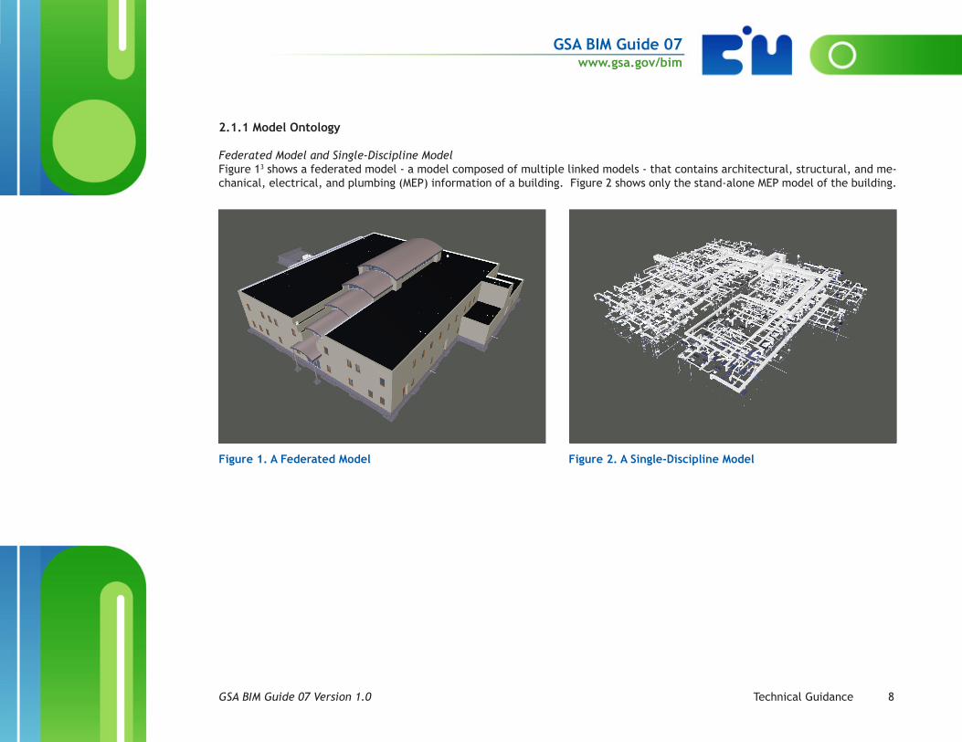
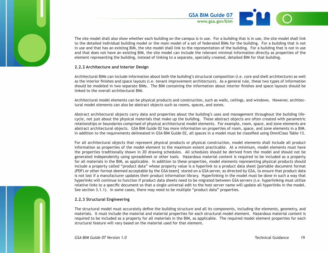
Federated Model and Single-Discipline ModelFigure 13 shows a federated model - a model composed of multiple linked models - that contains architectural, structural, and me-chanical, electrical, and plumbing (MEP) information of a building. Figure 2 shows only the stand-alone MEP model of the building.
Figure 1. A Federated Model Figure 2. A Single-Discipline Model

GSA BIM Guide 07www.gsa.gov/bim
GSA BIM Guide 07 Version 1.0 Technical Guidance 9
SystemWithin any model, information is generally categorized into systems by function. Figure 3 shows a single system within the MEP model: the supply air system for the first floor of the building. Figure 4 shows the same system without the rest of the model. Properties of this system might include name (e.g. First Floor Supply Air), classification (e.g. mechanical), and components. Section 2.2 provides more details about required properties for different systems.
Figure 3. Supply Air System Within an MEP Model FIgure 4. Supply Air System by Itself

GSA BIM Guide 07www.gsa.gov/bim
GSA BIM Guide 07 Version 1.0 Technical Guidance 10
Type and ComponentA system is composed of model elements called components, which can be categorized by type. In any model, there can be a single instance (i.e. a single component) of a component type or multiple instances (i.e. multiple components) of the same type. Figure 5 shows that there are multiple instances of the Variable Air Volume (VAV) component type in the supply air system. Figure 6 shows a single instance of the VAV component type. Properties of the VAV type can include manufacturer, model number, and product clas-sification (e.g. single duct, dual duct). Properties of a specific VAV component can include spatial information (e.g. room number where the VAV is located), system to which this component belongs, or serial number. Figure 7 shows that there is a single instance of the Air Handling Unit (AHU) component type in this system.
Figure 5. There are Multiple Instances of the VAV Component Type in the Supply Air System
Figure 6. A Single Instance of the VAV Component Type
Figure 7. There is One Instance of the AHU Component Type in the Supply Air System

GSA BIM Guide 07www.gsa.gov/bim
GSA BIM Guide 07 Version 1.0 Technical Guidance 11
A component type can exist in multiple systems. For example, the VAV component type can exist in a system defined as “first floor supply air” and also in another system defined as “second floor supply air”. The same instance of a component type may also belong to multiple systems. For example, an AHU can be part of the “first floor supply air” system and also part of the “first floor return air” system. In addition, while the AHU would be categorized as a mechanical component, it is also a component of the electrical system that provides its power. Figure 8 shows the different systems associated with the AHU in our example.
Figure 8. The Different Systems Associated with the AHU
Model ElementsThe term “model element” can describe any element in a model, regardless of its place in the ontology or its relation to other model elements; it can describe a component of a system or an instance of a component type. Thus, a model element can be a single part that is the smallest separable piece, or it can be an assembly that is composed of smaller elements (referred to as sub-elements). In Figure 9, both the AHU as a whole and its component sub-elements can be referred to as “model elements”.

GSA BIM Guide 07www.gsa.gov/bim
GSA BIM Guide 07 Version 1.0 Technical Guidance 12
Figure 9. The AHU and Its Sub-elements are All Model Elements4
2.1.2 Levels of Detail and Levels of Development
The architects, engineers, constructors, owners, and operators (AECOO) community uses two similar terms - both represented by the acronym “LOD” - to describe the quality of model information. In 2008, the California Integrated Project Delivery (IPD) Task Force of the American Institute of Architects (AIA) defined Levels of Detail (LODs) to describe “the steps through which a BIM ele-ment can logically progress from the lowest level of conceptual approximation to the highest level of representational precision.”5 That same year, the AIA defined the term Level of Development (LOD) in E202-2008 as “the level of completeness to which a Model Element is developed.” In 2013, a working group of AECOO professionals published a Levels of Development (LODs) specification through the Associated General Contractors of America (AGC) BIMForum organization to further refine what “LOD” means in both design and construction:
“Level of Detail is essentially how much detail is included in the model element. Level of Development is the degree to which the element’s geometry and attached information has been thought through – the degree to which project team members may rely on the information when using the model. In essence, Level of Detail can be thought of as input to the element, while Level of Development is reliable output.”6
All of these definitions are applicable for GSA, and the definition of LOD continues to evolve as industry further defines geometric and information requirements for building information. It is anticipated that new terms will be defined to separate these different

GSA BIM Guide 07www.gsa.gov/bim
GSA BIM Guide 07 Version 1.0 Technical Guidance 13
types of data requirements so that LOD for geometry and LOD for data or meta data can be defined separately. This guide will use the term “LOD” in a general way as context for the discussion of model development. As GSA further defines our geometric, data, and metadata requirements for a GSA BIM, this section will continue to evolve.
LOD levels start at LOD 100 and, in general, become progressively more detailed and more developed. LOD 500 represents as-built or actual conditions for various types of building information.
2.1.2.1 LOD 100
LOD 100 requires a low level of detail - roughly comparable to the level of detail traditionally associated with planning or conceptu-al design in a project. At this level, information is at its most primitive. For example, the building may be sited and roughly sized, and there may be a basic site layout. LOD 100 information is sufficient for performing some very preliminary types of engineering analysis that support high-level decision making about basic design. Examples include whole building energy analysis, building ori-entation daylight studies, conceptual cost estimates based on cost per square foot, and preliminary whole site construction phasing.
LOD 100 information may come in different formats because it can include engineering calculations, analysis data, and 2D drawings or sketches. LOD 100 information can be represented in a 3D model using generic “placeholder” objects that may or may not be accurately sized, dimensioned, or placed in the model. This would provide a framework for organizing other types of non-graphical or non-geometric information. However, a 3D model may not be the best way to represent the information. When possible, LOD 100 information should be in a format that will facilitate use of a BIM tool for further detail and development.
2.1.2.2 LOD 200 At LOD 200, generic model elements show approximate dimensions, quantities, locations, attributes, and relationships. There is sufficient information to inform design development and to answer high-level specific questions about spaces and systems. Howev-er, LOD 200 information is not necessarily sufficient for detailed analyses.
2.1.2.3 LOD 300
At LOD 300, specific model elements are fully defined in the BIM with exact dimensions, quantities, locations, attributes, and re-lationships. LOD 300 information should include all information that a design team would specify for a complete, biddable design package as delineated in the Facilities Standards for the Public Buildings Service (P100). LOD 300 information is sufficient for an estimator or contractor to provide a cost estimate for a project or to plan for the purchase, construction, and/or installation of specific building elements.
2.1.2.4 LOD 350
LOD 350 is a level in the AGC BIMForum LOD specification. Model elements at LOD 350 are defined with relationships within overall building systems, while model elements at LOD 300 are fully defined as specific, independent elements, assemblies, and systems.

GSA BIM Guide 07www.gsa.gov/bim
GSA BIM Guide 07 Version 1.0 Technical Guidance 14
2.1.2.5 LOD 400 LOD 400 provides sufficient detail in the BIM for fabrication and assembly. The information required for fabrication models is not necessarily the same as the information needed for design or as-built models, so LOD 400 models may have more or less information than LOD 300 or LOD 500 models, depending on the discipline. GSA does not specify information requirements for LOD 400; this is at the discretion of the contractor and fabricator.
2.1.2.6 LOD 500 LOD 500 fully defines the actual conditions of the facility. It is a virtual representation of the actual current conditions of the fa-cility.
As-built documentation of a facility, intended to provide a snapshot in time of the actual facility condition at the conclusion of a project, must be at LOD 500. Project team members, including the architect/engineer (A/E) of record, the construction manager (CM), and the general contractor (GC), must collaborate in order to incorporate design changes and field changes in a complete, coordinated as-built submittal that accurately represents the facility condition at the conclusion of the project. The as-built sub-mittal for a construction project should have field-verified LOD 500 information, including commissioning test results and other field inspection data. All commissioning test reports must be in digital format and must link to the appropriate BIM objects in the model. As GSA moves toward information-driven facility and asset management, GSA will require any data that is tested and verified by the commissioning authority be reconciled and included in the BIM deliverable as open standard [i.e. Construction Operations Building Information Exchange (COBie) compliant] data. Information related to operations and maintenance requirements must be provided in digital format as links to digital documents (such as operations and maintenance manuals) or as object data attributes in the BIM database. An LOD 500 as-built submittal does not necessarily contain all of the LOD 300 and LOD 400 information; it may incorpo-rate a combination of LOD 300 and LOD 400 information for some building elements with the addition of commissioning test results and other field inspection data. Models need not show excessive fabrication level detailing. For example, ductwork must be sized and located correctly as installed but need not have flanges modeled.
GSA requires field-verified as-built BIMs that can be relied on for facility and asset management, not just information for design and construction. As GSA moves toward information-driven facility and asset management, GSA intends to continue to maintain a current conditions model of the facility, incorporating changes to the building condition in the as-built documentation. GSA field personnel, including building managers and operating engineers, will work with the GSA Building Information Manager to ensure that the information in a current conditions model of a facility continues to meet the definition of LOD 500. At LOD 500, the model must be compliant with COBie as specified in GSA BIM Guide 08; models must be geometrically accurate and provide spatial data as specified in GSA BIM Guide 02; and models must be fully compliant with all published GSA model view definitions (MVDs) as of the project design start.

GSA BIM Guide 07www.gsa.gov/bim
GSA BIM Guide 07 Version 1.0 Technical Guidance 15
2.1.2.7 Changes to LODs There is discussion in industry about whether the LODs as currently defined sufficiently meet the needs of all phases of the asset or facility lifecycle. If industry chooses to redefine existing LODs or to define new LODs for uses beyond the regular project lifecycle, GSA will review and incorporate them as appropriate.
2.1.3 Model Progression Matrix (MPM)
For every project, the project team must create a custom model progression matrix (MPM) to indicate the LOD for various types of data and disciplines, as required by project needs, and the MPM must be a part of the project BIM execution plan (BEP). For exam-ple, a tenant fit-out project may need higher LOD information about architectural finishes early in the project but require only a low LOD for mechanical information throughout the project, whereas a mechanical upgrade project may require low LOD architectural information even at project close-out but will require higher LOD mechanical information at early design stages. Similarly, a project scope of work may define that a Design Development deliverable for a historic restoration project must be at LOD 200, but the MPM may define that certain historic architectural details must be defined to LOD 300 even at this early stage.
A general LOD can be defined for a specific project deliverable. The project MPM must clearly delineate which spaces, disciplines, or equipment are at a higher or lower LOD than the general LOD set for the deliverable. For example, a partial building modern-ization may require LOD 200 for the Design Development deliverable but may indicate that areas outside the specific area of work may remain at LOD 100 throughout the design and construction process.
Various organizations have published sample MPM formats, including the following:
• The National BIM Standard-United States Version 3 (NBIMS-US V3) Section 5.8.4.3.5 outlines “Minimum Modeling Requirements”.• AGC BIMForum 2015 LOD Specification provides an MPM template and an element attribute table that specifies the properties
required for various elements at different LODs.
In some cases, the different standards may contain variations in LOD definitions. The project team must be careful to specify which standard and definition is in use for a given project. For more information, contact the national BIM program office or the regional BIM champion.

GSA BIM Guide 07www.gsa.gov/bim
GSA BIM Guide 07 Version 1.0 Technical Guidance 16
Figure 10. Sample Model Progression Matrix
PROJECT NAME:ADDRESS / CITY / STATE:
DATE:REVISED DATE:
Model Element Name In ProjectScope? Model Element ID Master
Format IDOmniClassTable 21 ID
OmniClassTable 23 ID FACTS Code Design
Devel.Model Element
Author Constr. Bid Model ElementAuthor As-Builts Model Element
AuthorNOTE: This Model Progression Matrix is only anexample. All MPM's must be customized to list onlyproject scope items pertinent to each project.
LOD ***Project Defined* LOD ***Project Defined* LOD ***Project Defined*
FOUNDATIONS Yes A10 21-01 10 23-11 11 11 11 D303001.04.01.01.01 100 Engineering Firm 300 Engineering Firm 500 CMc / AE / GC
Standard Foundations Yes A1010 21-01 10 23-11 11 11 11 11 D303001.04.01.01.02 200 Engineering Firm 350 Engineering Firm 500 CMc / AE / GC
Wall Foundations Yes A1010.10 21-01 10 10 23-11 11 11 11 13 D303001.04.01.01.03 100 Engineering Firm 350 Engineering Firm 500 CMc / AE / GC
Etc.....
SUBGRADE ENCLOSURES No
Walls for Subgrade Enclosures No
Vaults No
Etc.....
SLABS ON GRADE Yes A40 21-01 10 20 40 23-11 13 00 D303001.04.03.01.01 200 Structural Firm 300 Structural firm 500 CMc / AE / GC
Standard Slabs-on-Grade Yes A4010 21-01 10 20 50 23-11 13 11 D303001.04.03.01.02 200 Structural Firm 300 Structural firm 500 CMc / AE / GC
Structural Slabs-on-Grade No
Etc.....
WATER AND GAS MITIGATION Yes A60 31 23 23 21-01 10 20 70 23-11 13 11 13 D303001.04.03.02.02 100 Architecture Firm 300 Architecture Firm 500 CMc / AE / GC
Building Subdrainage Yes A6010 21-01 10 20 80 23-11 13 11 15 D303001.04.05.01.01 100 Architecture Firm 300 Architecture Firm 500 CMc / AE / GC
Foundation Drainage No
Etc.....
SUBSTRUCTURE RELATED ACTIVITIES Yes A90 31 21 16 21-01 20 10 10 23-11 13 11 17 13 D304007.04.02 100 Structural Firm 300 Structural Firm 500 CMc / AE / GC
Substructure Excavation Yes A9010 21-01 20 10 20 23-11 13 11 19 D305006.01.01.01 200 Structural Firm 300 Structural Firm 500 CMc / AE / GC
Backfill and Compaction Yes A9010.10 31 23 16 21-01 20 10 90 23-11 13 13 D305006.01.01.02 200 Structural Firm 300 Structural Firm 500 CMc / AE / GC
Etc.....
SHELL Yes B 31 31 00 21-01 40 20 23-11 13 13 15 D305006.01.02.03 200 Structural Firm 300 structural firm 500 CMc / AE / GC
Superstructure Yes B10 21-01 40 30 23-11 13 13 15 11 D305006.02.01.01 200 Structural Firm 350 structural firm 500 CMc / AE / GC
Floor Construction Yes B1010 21-01 40 40 23-11 13 13 15 13 D305006.02.01.02 200 Structural Firm 350 structural firm 500 CMc / AE / GC
Etc.....
EXTERIOR VERTICAL ENCLOSURES Yes B20 05 51 23 21-01 60 10 10 23-11 15 11 21 D304008.01.04 200 Architecture Firm 300 Architecture Firm 500 CMc / AE / GC
Exterior Walls Yes B2010 21-01 60 10 20 23-11 15 11 23 D201003.01.04.01.01 200 Architecture Firm 300 Architecture Firm 500 CMc / AE / GC
Parapets Yes B2010.50 21-01 60 20 23-11 15 11 25 D201003.01.04.02.01 200 Architecture Firm 300 Architecture Firm 500 CMc / AE / GC
Etc.....
DOORS Yes B2030 21-01 90 23-11 15 13 13 D201003.02.02.01.01.0 200 Architecture Firm 300 Architecture Firm 500 CMc / AE / GC
Exterior Doors and Grilles Yes B2050 08 56 00 21-01 90 10 23-11 15 13 15 D201003.02.02.01.02.0 200 Architecture Firm 300 Architecture Firm 500 CMc / AE / GC
Exterior Entrance Doors Yes B2050.10 21-01 90 10 10 23-11 15 13 17 D201003.02.03.01.01.0 200 Architecture Firm 300 Architecture Firm 500 CMc / AE / GC
Etc.....
EXTERIOR HORIZONTAL ENCLOSURES Yes B30 10 74 00 21-01 90 30 40 23-11 17 13 11 D201003.02.05.01.02.0 100 Architecture Firm 350 Architecture Firm 500 CMc / AE / GC
Roofing Yes B3010 21-01 90 30 60 23-11 17 13 11 11 D201003.02.06.01.01.0 200 Architecture Firm 350 Architecture Firm 500 CMc / AE / GC
Steep Slope Roofing No
Etc.....
INTERIOR CONSTRUCTION Yes C10 21-02 10 10 50 23-11 17 13 27 D304008.09.01 100 Architecture Firm 300 Architecture Firm 500 CMc / AE / GC
Interior Partitions Yes C1010 21-02 10 10 90 23-11 17 13 29 D304008.10 100 Architecture Firm 400 Architecture Firm 500 CMc / AE / GC
Interior Fixed Partitions No 100 Architecture Firm 350 Architecture Firm 500 CMc / AE / GC
Etc.....
Model Progression Matrix (MPM) Example
Colorado Federal Building PROJECT DESCRIPTION:1234 Main Street, Denver, CO 80202 Remodel and modernization of a mid-century modern office building. Scope
includes new curtain wall, HVAC upgrades, lighting upgrades, Lobbyremodel, landscaping, security system upgrades, wedge barriers, BuildingAutomation System Upgrades
1 June 2015
25 July 2016 Project Phase
*Note: codes for example purposes only not all are correct
Do not populate fields if not in scope.

GSA BIM Guide 07www.gsa.gov/bim
GSA BIM Guide 07 Version 1.0 Technical Guidance 17
2.2 Model Element General Requirements
GSA has general and specific requirements for model elements. This guide discusses GSA’s general requirements. GSA will utilize a combination of tools as appropriate to provide more specific requirements. These tools include MVDs, common object libraries, data dictionaries, and model element matrices. Industry and government entities use these more specific tools to address relation-ships and attributes of model element information as well as relationships of model elements to each other, to project milestones, and to project and building stakeholders. GSA has published some MVDs within the NBIMS-US, and GSA intends to publish additional MVDs in support of this guide.
This section is organized in parallel to the P100 for ease of use by the GSA design and construction community. As with all design requirements, project teams must comply with the P100 BIM requirements in terms of information to include in the model for each design submission and to what LOD to define that information. The GSA Project Manager and the GSA national BIM program must approve any proposed deviation from the P100 BIM requirements, and the project team must document the deviation in the project BEP.
Note that this section discusses general information. In some cases, this may apply to the design team, the construction team, third-party quality managers, or any combination thereof. The exact timing and responsibilities for providing information in the BIM should be documented clearly in the BEP.
Project teams must identify SBU information in the BIM(s) during all phases of the project. They must reference GSA’s directive on Document Security for Sensitive But Unclassified Building Information for labeling and handling SBU information, and they must tag the SBU information in a way that allows displaying and hiding the SBU information appropriately and at the authorized level. Note that SBU information must be specific to the model elements, and project teams shall not label an entire BIM as SBU by default. Contractors must coordinate with the GSA project team and comply with SBU requirements for projects and models in order to properly designate and label only the appropriate parts of the models as SBU. The BEP or the narrative submittal for the deliver-able should include a narrative describing what project information is designated as SBU, and the BEP should also indicate how SBU is designated within the model. GSA intends to maintain a current conditions model of the facility, incorporating changes to the building condition in the as-built documentation. GSA field personnel, including building managers and operating engineers, will work with the GSA Building Information Manager to validate that the BIM correctly identifies SBU information in an ongoing manner during normal building operations.
2.2.1 Urban Development and Landscape Design
2.2.1.1 Base Points
All GSA building information models (native and IFC) - including site-only models - must contain site information that is properly positioned in accordance with a coordinate system in the model space and with a geographic coordinate system in the real world. Note that models that do not include site information in their primary authoring tool will not be able to export the required location information to IFC.

GSA BIM Guide 07www.gsa.gov/bim
GSA BIM Guide 07 Version 1.0 Technical Guidance 18
Every model must have a site base point, or survey point, that provides a measurable location in the physical world to help correctly orient the building. The site base point must be in the BIM of any building or project on the site. The site base point data must be properly mapped so that it exports to the IFC footprint and IFC survey point elements.
For a model of a single building, the site base point should correspond to the latitude and longitude that GSA has on record for the building. For a site with multiple buildings, all the individual BIMs on the site shall use the latitude and longitude that GSA has on record for the largest building on the site as their site base point. The site base point should also include the elevation of the point. Coordinate with the GSA asset manager and the GSA national geographic information systems (GIS) program to determine what geospatial information is on record. GSA recommends using an actual United States Geological Survey (USGS) survey point, if available, to establish this base point, which facilitates georectification of the model.
For a specific project, the project team may establish a convenient project base point at a different location from the site base point for the building. A project base point is especially useful when a project touches only a portion of a building or when a build-ing is located on a multi-building site. In general, the project team should select a project base point that is compatible with the needs and structures of the various software platforms that will be used on the project. This project base point defines the origin (0,0,0) of the coordinate system of the BIM data for that project. The project team shall document in the project BEP a project base point that is different from the site base point.
If there is a project base point in an existing BIM, any subsequent project in the same building shall use the same project base point, unless there is a compelling reason to select a new project base point. If a project team selects a new project base point, the BEP must document the reason for selecting a new project base point.
The BEP must define Project North in relation to True North. All BIM data for the project must use these defined directions consis-tently.
2.2.1.2 Site and Campus Models
Site models must include civil utilities to the maximum extent practicable. In particular, the site model for a campus that is wholly owned or managed by GSA must include modeling of civil utilities. Civil utilities must be mapped to IFC civil data elements and classified by OmniClass7 Table 21, and they should include vaults, raceways, etc., as required. In order to ensure accurate data for modeling, utilities should be a part of the site survey. Direct burial utilities should be located by a qualified utility location service, with a special flag at any turn or deviation from straight-line run.
Any GSA property that is part of a campus - including, but not limited to, land ports of entry and urban federal center campuses - requires a separate site model. This site model shall show the geographic locations of all the individual buildings on the campus and shall also contain the locations and civil engineering data associated with the site utilities, roads, parking areas, and service structures. The buildings shown on the site model shall be lightweight models illustrating only the general size and shape of the building and the utility penetrations to the buildings. When applicable, the site model shall clearly indicate that the buildings share utilities.
GSA BIM Guide 07www.gsa.gov/bim
GSA BIM Guide 07 Version 1.0 Technical Guidance 19
The site model shall also show whether each building on the campus is in use. For a building that is in use, the site model shall link to the detailed individual building model or the main model of a set of federated BIMs for the building. For a building that is not in use and that has an existing BIM, the site model shall link to the representation of the building. For a building that is not in use and that does not have an existing BIM, the site model can include the relevant minimal information directly as properties of the element representing the building, instead of linking to a separate, specially created, detailed BIM for that building.
2.2.2 Architecture and Interior Design
Architectural BIMs can include information about both the building’s structural composition (i.e. core and shell architecture) as well as the interior finishes and space layouts (i.e. tenant improvement architecture). As a general rule, these two types of information should be modeled in two separate BIMs. The BIM containing the information about interior finishes and space layouts should be linked to the overall architectural BIM.
Architectural model elements can be physical products and construction, such as walls, ceilings, and windows. However, architec-tural model elements can also be abstract objects such as rooms, spaces, and zones.
Abstract architectural objects carry data and properties about the building’s uses and management throughout the building life-cycle, not just about the physical materials that make up the building. These abstract objects are often created with parametric relationships or boundaries comprised of physical architectural model elements. For example, room, space, and zone elements are abstract architectural objects. GSA BIM Guide 02 has more information on properties of room, space, and zone elements in a BIM. In addition to the requirements delineated in GSA BIM Guide 02, all spaces in a model must be classified using OmniClass Table 13.
For all architectural objects that represent physical products or physical construction, model elements shall include all product information as properties of the model element to the maximum extent practicable. At a minimum, model elements must have the properties traditionally shown in 2D drawing schedules. All schedules should be derived from the model and should not be generated independently using spreadsheet or other tools. Hazardous material content is required to be included as a property for all materials in the BIM, as applicable. In addition to these properties, model elements representing physical products should include a property called “product data” whose property value is a hyperlink to a product data sheet [portable document format (PDF) or other format deemed acceptable by the GSA team] stored on a GSA server, as directed by GSA, to ensure that product data is not lost if a manufacturer updates their product information library. Hyperlinking in the model must be done in such a way that hyperlinks will continue to function if product data sheets need to be migrated between GSA servers (i.e. hyperlinking must utilize relative links to a specific document so that a single universal edit to the host server name will update all hyperlinks in the model. See section 3.1.1). In some cases, there may need to be multiple “product data” properties.
2.2.3 Structural Engineering
The structural model must accurately define the building structure and all its components, including the elements, geometry, and materials. It must include the material and material properties for each structural model element. Hazardous material content is required to be included as a property for all materials in the BIM, as applicable. The required model element properties for each structural feature will vary based on the material used for that element.

GSA BIM Guide 07www.gsa.gov/bim
GSA BIM Guide 07 Version 1.0 Technical Guidance 20
The structural model must contain clearly labeled and fully dimensioned beam, column, and foundation elements. The structural elements of a building must capture reinforcing and connections explicitly, along with connection details, material properties, cross-section proper-ties, assigned structural analysis models, load cases (including wind, snow, thermal expansion, seismic, and others as required), load combi-nations, and load results for the relevant combinations. Similarly, model elements which are part of progressive collapse and blast mitigation shall be explicitly identified and defined, at a minimum, as SBU. Some or all of these elements may require a higher security classification, depending upon building type and occupancy. Consult the GSA Project Manager to clarifiy SBU status.
The structural model shall contain all necessary elements needed to evaluate and analyze the building structure either by tradition-al methods or by any commonly used structural simulation software under load assumptions set by governing building codes [such as those published by the American Concrete Institute (ACI), the American National Standards Institute (ANSI), and the American Institute of Steel Construction (AISC)]. Due to the complexity of the many different types of structural load cases, it is crucial that the structural system be correctly modeled so that the linear and nonlinear analyses commonly performed to evaluate seismic loads on building structures are reliable and accurate.
At a minimum, structural models must contain the following elements:
• Foundations: All components of the foundation, including but not limited to isolated pads, bearing and retaining footings, stem walls, structural slabs, and piles, must be fully modeled.
• Horizontal elements: All beams, joists, slabs, and precast slabs must be fully modeled. The model must show slab perimeters and structural edges; penetrations for shafts, holes, or other slab discontinuities; and cantilevered sections.
• Vertical elements: All columns, walls, and cross bracing must be fully modeled. All connections and start/end points of such ele-ments must be modeled to allow load continuity.
• Inclined planes: Any inclined structural element, including but not limited to non-plumb walls, stairs, ramps, and roofs.• Abstract structural elements, including but not limited to loads and load distributions.
In addition to the elements listed above, the structural model shall include any additional structural elements as required by the building design. All structural elements shall be properly joined so that the structural design model can be used for analysis, fab-rication, and other purposes.
Projects involving historic buildings require special care with structural elements. In many cases, the building structure must be preserved due to historic or cultural interests; in these cases, it may be necessary to model the building structure to a high LOD earlier in the process and to maintain a high LOD structural model. The design team should use the appropriate tools, including laser scanning, to accurately represent these elements for use in both structural analysis and historic preservation. More information about laser scanning and other imaging technologies is available in GSA BIM Guide 03.
2.2.4 Mechanical, Electrical, Plumbing (MEP) and Fire Protection (FP) Engineering
The MEP model(s) shall accurately depict the building’s MEP systems, including (but not limited to): boilers, chillers, geothermal and solar energy systems; pumps and piping distribution systems, water-side terminal units; fans, air handlers, air distribution and evacuation systems, air-side terminal units, VAV boxes; electrical feed and distribution systems, transformers, electrical panels and switchgear, lighting, emergency circuitry, emergency generators; all public utility systems from tap, all control systems, data and

GSA BIM Guide 07www.gsa.gov/bim
GSA BIM Guide 07 Version 1.0 Technical Guidance 21
phone wiring and terminal devices, data switches, data rooms. The default set of assets that should be included in the MEP model(s) is all assets that were traditionally shown in 2D drawing schedules. See GSA BIM Guide 08 for additional detail.
Fire protection models must include information regarding fire ratings based on UL for standardized assemblies; material properties for combustion for all physical elements; sprinkler locations, sprinkler medium, sprinkler head temperatures, pressure and flow volume based on field measurements.
For modeling related to a project, consult a GSA Facility Manager [or Equipment Manager or building automation system (BAS) Spe-cialist] familiar with the building to determine if there is any special equipment that must be modeled or if there are any asset types that do not need to be modeled. Consult the GSA Facility Manager for every deliverable review for which there is mechanical design content at the concept level or beyond. Document any additions or subtractions from the default set of assets in the project BEP.
For all products in MEP in models, the model elements must include all appropriate data and properties to store schedule information traditionally embedded in a 2D drawing schedule. Hazardous material content is required to be included as a property for all elements in the BIM, as applicable. The model elements must also include a property called “product data”. The property value for this property should be a hyperlink to a product data sheet stored on a GSA server, as directed by GSA, to ensure that product data is not lost if a manufacturer updates their product information library. Hyperlinking in the model must be done in such a way that hyperlinks will continue to function if product data sheets need to be migrated between GSA servers (i.e. hyperlinking must utilize relative links to a specific document so that a single universal edit to the host server name will update all hyperlinks in the model. See section 3.1.1). In some cases, there may need to be multiple “product data” properties. For example, a chiller may have multiple documents associated with it, including an equipment cut sheet, an operation and maintenance (O&M) manual, and a warranty document. This data must comply with all COBie requirements and all requirements of GSA BIM Guide 08.
It is important to note that some architectural or structural model elements may have associated mechanical or electrical proper-ties. For example, building envelope elements such as curtain wall panels and roof materials are required to include the mechanical or energy design properties such as insulation thickness, roof reflectance, and glazing thermal coefficients.
It is also important to check that the MEP systems in the model are properly split to show which equipment is serving which spaces or floors. Modelers must be careful to ensure that system assignments made in the native authoring software are properly reflected in the IFC deliverable.

GSA BIM Guide 07www.gsa.gov/bim
GSA BIM Guide 07 Version 1.0 Technical Guidance 22
2.2.5 Other
Numerous specialties are involved in the design of a building, and the specialty information must be recorded in the model.
For some specialties, the necessary information can be included as a property of an element in the model. For example, hazardous materials can be identified by a simple yes/no property directly associated with the element. Similarly, the level of classification of a design feature (e.g. not sensitive, sensitive but unclassified, classified) or the historic status of a building or a model element (e.g. listed on the national register, eligible to be registered) can also be identified by a simple designation on the model element.
However, some specialties will require more information to be included in the model than can be captured in a single property. For example, security equipment may or may not be in the electrical model. If security equipment is modeled in a separate security model, it must be properly referenced for inclusion in the federated model. Many security features of a building will require a different set of properties from regular electrical equipment.
2.3 Naming Conventions
Standardized naming conventions are required to achieve clear and concise naming for BIM-related data and promote effectiveness when working with BIM. The guidelines listed below apply to any object present in a dataset at the time of delivery to the GSA.
2.3.1 General Guidelines
The intent of using standardized naming conventions is to enable human users of files or data to effectively and efficiently locate relevant information. Therefore, whenever possible, use plain language descriptive text, rather than any sort of alphanumeric code, to name files or objects. All descriptive text (in file names, object labels, or attributes, etc.) should be in English. Non-English manufacturer names are acceptable.
Files and objects may not be named using personal designations. For example, “John’s working model” is not an acceptable file name.
Consult the GSA project team for GSA standard naming conventions. Where there is no GSA standard naming convention, use a consistent naming convention for the project. Any project-specific naming convention must be approved by the GSA project team and noted in the project BEP.
Consult the GSA project team for GSA standard abbreviations. Where there is no GSA standard abbreviation, use a consistent abbre-viation for the project. Any project-specific abbreviation must be approved by the GSA project team and noted in the project BEP.

GSA BIM Guide 07www.gsa.gov/bim
GSA BIM Guide 07 Version 1.0 Technical Guidance 23
2.3.2 File Naming Conventions
2.3.2.1 Metadata Required for Internal GSA Current Conditions File Management
GSA is managing building information with a focus on clear identification of current building information, or “current conditions”. The following metadata is required for all files:
• GSA Building Number• GSA Building Name• Region• Building Address• Building City• Building State• Building Zip Code• Floor (or Floors)* (see below for additional discussion)• File Name• File Status (Pending, Current, Archive)• File Created Date• File Created By (Author)• File Modified Date• File Modified By (Author)• File Type• Data Type• Discipline** (see below for additional discussion)• Long Description
◦ Include version of authoring software ◦ Include any region-specific metadata with appropriate tags
For computer-aided design (CAD) drawings, the following additional fields are required:
• Drawing Number• Drawing Title
For any file generated in the context of a project, the following additional fields are required:
• Project Number• Project Title• Project Description• Project Phase (Concept, Construction Documents, As-Builts)• Submission Date• Design Complete Date

GSA BIM Guide 07www.gsa.gov/bim
GSA BIM Guide 07 Version 1.0 Technical Guidance 24
• Construction Complete Date• A/E Name• A/E Contract Number• GC Name• GC Contract Number• GSA Project Manager
*Floors/Levels in a BIM file or a sheet view shall be named in accordance with the latest version of the PBS CAD Standards. In the March 2012 version of the PBS CAD Standards, floor naming conventions are found in Item 15 (page 3).
**Current conditions information for a GSA building is organized by discipline, utilizing the framework provided by the P100. There-fore, information provided to GSA by project teams must be clearly identifiable by these disciplines. Discipline naming conventions are indicated in the PBS CAD Standards (Item 14 of the March 2012 version; later versions will govern when published). In general, code disciplines in accordance with the United States National CAD Standard (NCS), with adjustments as described in the PBS CAD Standards.
2.3.2.2 File Naming Conventions for Projects
Naming conventions for CAD and for sheet views extracted from BIM must comply with the PBS CAD Standards. Naming conventions for BIM files should comply with Table 1:
Table 1. Naming Convention for BIM Files
Number of Characters Example Notes Reference
Building Number 8 followed by an under-score
DC0021ZZ_
Discipline designator 1 or 2 followed by an underscore
A_ Typically 1 character for the major discipline.In cases where there are multiple models for the same discipline, a second character may be added to indicate the minor discipline.
NCS (latest version)+PBS CAD Standards (latest version)
Floor Number or Range 2-5 01-07 PBS CAD Standards (latest version)
End with file extension 3 .ifc

GSA BIM Guide 07www.gsa.gov/bim
GSA BIM Guide 07 Version 1.0 Technical Guidance 25
Some sample file names that comply with this schema are below:
• DC0021ZZ_A_01-07.rvt (multi-floor architectural model)• CO0009ZZ_M_SB.ifc (sub-basement mechanical model)
2.3.3 Model Element Naming Conventions
Model element names should be in compliance with naming conventions established for a specific discipline. For example, maintain-able equipment must be classified and named in compliance with GSA’s Facility Asset Component Tracking System (FACTS), which is also published as ASTM Standard E3035-15. Similarly, space objects must be classified and named in compliance with GSA’s National Business Space Assignment Policy (NBSAP). Consult the GSA project team or the National BIM Program Expert for discipline-specific information about model element naming.
In addition, model elements must be classified and designated with the appropriate Omniclass codes.

GSA BIM Guide 07www.gsa.gov/bim
GSA BIM Guide 07 Version 1.0 Practical Guidance for Modelers 26
Section 3Practical Guidance for Modelers
GSA BIM Guide 07www.gsa.gov/bim

GSA BIM Guide 07www.gsa.gov/bim
GSA BIM Guide 07 Version 1.0 Practical Guidance for Modelers 27
3 Practical Guidance for ModelersThis section includes practical guidance for working with building information modeling (BIM) files, creating accurate Industry Foun-dation Classes (IFC) models, and checking models against the General Services Administration’s (GSA’s) requirements.
In general, GSA requires compliance with the BIM guidance in the following documents, in order of precedence:
• Facilities Standards for the Public Buildings Service (P100),• GSA BIM Guide series,• GSA PBS CAD Standard,• National BIM Standard-United States (NBIMS-US), and • United States National CAD Standard (NCS).
3.1 Best Practices for Modeling
3.1.1 Model References
Graphical files (i.e. drawings or models) should always be referenced base point to base point [i.e., (0,0,0) to (0,0,0)]. Different models of the same building must all utilize the same base point. See section 2.2.1.1 for more information on establishing base points for a model.
All references must have relative paths, rather than absolute paths. The relative path should begin from the main model directory, as demonstrated below.
• Examples of valid use: ◦ Concrete\Warranty Info\Warranty.pdf ◦ .\Concrete\Warranty Info\Warranty.pdf
• Example of invalid use: ◦ E:\Models\Concrete\Warranty Info\Warranty.pdf
References to objects in other models and links to external documents must also use relative paths.
Avoid reference nesting, especially on project-based BIM platforms. Each reference should be a direct reference to the required information, so that there is no need for multiple click-throughs from reference to reference.

GSA BIM Guide 07www.gsa.gov/bim
GSA BIM Guide 07 Version 1.0 Practical Guidance for Modelers 28
3.1.1.1 Referencing vs. Inserting
When referencing information in a model, the information remains in its original location and is managed and edited in its original location. When inserting information into a model, the information becomes natively a part of the model and will be managed and edited in the model going forward.
In general, only reference - do not insert - information that is located in a database or file repository. However, it is sometimes desirable to insert information from an external source directly into a model. This usually only occurs when the information is a model object in another model.
Consider these basic rules when deciding whether to reference or insert information:
• Each real world object shall exist in only one model. If the information is useful in more than one model, locate it natively in one model, then reference it in the other models.
• The model in which an object is natively located is the model that “owns” that object. Inserting an object into your model means that you are taking ownership of that object: you will continue to manage and edit the information related to that ob-ject. If you are not the party responsible for managing and editing that information, reference the object instead of inserting it.
• When there is a genuine need to insert information into a model, ensure that the inserted object and the model are of the same data format. When this is not the case, convert the information into the format of the model before insertion. For example, it is preferable to convert 2D DWG data into 3D BIM data prior to inserting the 2D data into the building information model (BIM) even though it is possible to insert 2D data directly into the BIM.
3.1.2 Federated or Linked Models
If there is more information for a building or a project than can be reasonably contained in a single model, it may be appropriate to divide the building information into a federated set of models. It is important to consult the downstream GSA users of the BIM deliverables, including the building’s facility manager, before deciding how to assign the different sets of information into the separate models and how to link the models into a federated model. When doing this for a project, the contractor must document these decisions in the BIM execution plan (BEP).
Modelers should check to ensure that linked models are properly scaled and positioned so that they align when opened simultane-ously. For example, it is important to ensure that a mechanical, electrical, and plumbing (MEP) model is properly referenced to the architectural model so that when they are linked together and loaded together, the MEP systems appear inside the building, in the correct positions, and at the correct scale.

GSA BIM Guide 07www.gsa.gov/bim
GSA BIM Guide 07 Version 1.0 Practical Guidance for Modelers 29
When a federated model is a project deliverable, it must include the main model and all linked models. The main model must include all necessary links between models, and each model must open independently without any opening errors.
When a modeler links to a file for working purposes [for example, when a modeler links to a computer-aided design (CAD) back-ground as a basis for modeling], but the file is not required in the final model deliverable, then the modeler must unlink and unload the unnecessary file from the main model prior to submitting the deliverable. The project deliverable shall only include live and necessary files.
3.1.3 Collaboration on Models
During a project, modelers often use workflow tools within a model authoring software to aid collaboration. All workflow assign-ments must be removed from the model prior to submission as a project deliverable.
3.1.4 Standard and Custom Model Views
GSA recommends including standard model views to isolate the major systems and major assets identified in the Construction Op-erations Building Information Exchange (COBie) information delivery plan. Other standard model views, such as those for spaces of interest to general or specific building tenants, may also be useful. The project team should consult with downstream model users, such as the building management team, to determine what additional default model views to include in the model and document the determinations in the BEP. Contact the national BIM program office or a regional BIM champion for more information.
If the project team sets up custom model views for the convenience of project execution, it may choose to leave them in the final model deliverable for downstream users. The project team must document such a decision in the BEP.
3.1.5 Modeling Existing Buildings
When it is advantageous to model an existing building in whole or in part, it is not always practical to meet all the requirements defined in section 3. There are two major instances where less information may be more appropriate:
• For limited scope projects, a limited scope BIM (LS-BIM) would document only a limited amount of building information, with “limited” defined either spatially (e.g. all the information for a single floor or floors) or by discipline (e.g. only me-chanical equipment, either for an entire building or for a limited and defined portion of the building). Since the LS-BIM will later merge with other LS-BIMs to compile a complete current conditions model for the building over time, it is not appro-priate to invest resources to document the building to a higher level of detail than is immediately required, as that addi-tional detail may ultimately make merging the models more difficult. In general, use LS-BIMs for limited scope proj-ects, and limit the level of detail required in the model according to the level defined in the project scope. For these limited scope projects, focus only on information required for the project or application that is driving the scope limitation.

GSA BIM Guide 07www.gsa.gov/bim
GSA BIM Guide 07 Version 1.0 Practical Guidance for Modelers 30
• For non-project-related modeling efforts, a BIM of an existing building (EB-BIM) would document all the disciplines and all the spaces but would not necessarily include all the detail required in a design or construction model. For example, information about con-structability or purchasing may be less relevant. The required level of detail for EB-BIMs may vary greatly, depending on the reason for developing the EB-BIM. See section 3.1.5.1 for additional information.
LS-BIMs and EB-BIMs may include basic spatial arrangements and relationships, basic shell and fenestration details, basic properties of how the building is constructed, e.g. foundation, wall, floor, and roof thicknesses and materials. These two types of BIMs are often produced using as-built CAD drawings as the basis of the model and then enhanced with field investigation. These BIMs represent a snapshot in time and serve as “information platforms” to accurately represent buildings as they stand. They can be used for many ongoing applications in facility and asset management, including work order management, preventive/periodic maintenance, building controls management, spatial data management, and documentation and maintenance of current conditions.
3.1.5.1 LOD for EB-BIMs
EB-BIMs will require varying levels of detail (LODs) and levels of development (LODs) based on their intended use:
1. For EB-BIMs intended for ongoing management of the building/facility, LOD 500 may be required for all model elements rep-resenting managed assets. However, assets that are not managed (such as fixtures or spaces) may be modeled only as needed to provide context for the managed assets.
2. For EB-BIMs intended as a platform for spatial data and rent bill management, space and architectural information may require LOD 500, while model elements for other disciplines, or even some model elements within the architectural discipline, may only require LOD 100 or require no model at all.
3. For EB-BIMs intended to serve as the basis of design for subsequent construction projects, during which normal due diligence investigatory work would be undertaken by the project architect/engineer (A/E), the required LOD may be only 100 or 200 for model elements of any discipline, as the EB-BIM will be merged with higher LOD LS-BIMs from future projects.
Over time, the lower LOD elements in any EB-BIM can be supplemented by merging higher LOD LS-BIMs with the EB-BIM. The EB-BIM can sometimes become the current conditions model for the building, to be used across GSA business lines for many purposes.
3.1.5.2 Determining LOD for EB-BIMs
LOD requirements will vary according to building type, size, age, use, and potential for modernization, and they will need to be tailored specifically for each building in order for the BIM to be sufficiently representative. Sometimes more complex model el-ements (such as structural components or MEP systems) can and should be included if accurate as-built drawings exist, but only if the intended use merits it. Generally, some indication of all major system components should be included, but only to the extent required for model context or immediate use.

GSA BIM Guide 07www.gsa.gov/bim
GSA BIM Guide 07 Version 1.0 Practical Guidance for Modelers 31
Setting the appropriate LOD for an EB-BIM project is important because the goals of modeling an existing building can vary widely, and they are not as clearly defined as the goals of modeling for a design or construction project. There tends to be a direct rela-tionship between LOD and modeling cost, so it is important to clarify the goals of the modeling effort in order to determine the appropriate LOD and thus justify the cost of modeling. Note that the LOD does not need to be uniform for all disciplines even within a single building. Some buildings may require only a very low LOD for the building architecture, but a high LOD for the building MEP, and vice versa.
Listed below are some guidelines for determining the appropriate LOD for different situations:
• Building Types: Some building types are significantly more complex than others. A higher level of complexity may necessitate a higher LOD for the building model. For example, laboratory facilities often have complicated infrastructures and thus may warrant a higher LOD than a standard office building. Similarly, large data centers may be architecturally simple but have complex heating, ventilation, and air conditioning (HVAC) and electrical systems, therefore requiring a higher LOD.
• Building Size: Since larger buildings tend to have more complex building systems, larger buildings often require a higher LOD. Con-versely, models of very small buildings can have less detail while still being sufficiently representative.
• Building Age: The age of a building can have an impact on the LOD needed. For example, many historic structures are more ornate and will require more detailed architectural models to accurately document the condition of the building. On the other hand, a newer building might have more complex building systems or control systems that could necessitate a higher LOD for the mechanical model.
• Building Use: The use of a building can drive complexity. For instance, an office building with judicial tenants may seem like a reg-ular office building. However, it may require a higher LOD to properly document the building or specific spaces within the building due to security requirements - such as blast protection or circulation controls - as well as special space types - such as holding cells or sally ports - within the building.
• Potential for Modernization: If a major investment is planned for a building within 3-5 years, it is necessary to consider whether modeling the building:
◦ in conjunction with the modernization project is more cost effective and efficient for the project team, or
◦ prior to the modernization project will allow for a more focused modeling effort, provide a better baseline for the project, and enable a more rapid project start.
If modeling is done in advance of an expected project, a higher LOD may be appropriate in order to ensure that the baseline BIM provided to the project team contains all relevant information. On the other hand, a lower LOD may be appropriate as some of the detail of the existing building may be changed by the upcoming project and can be filled in later by the project team.

GSA BIM Guide 07www.gsa.gov/bim
GSA BIM Guide 07 Version 1.0 Practical Guidance for Modelers 32
3.2 IFC Models
3.2.1 Exporting to IFC
3.2.1.1 General Guidelines for Exporting to IFC
While GSA is vendor-neutral and allows the use of any native authoring tool, it highly recommends using an IFC-certified tool. Use the latest (or most appropriate) version of IFC, the native authoring tool, and the IFC export tool. As a best practice, use a native authoring tool that incorporates a fully supported IFC export tool. Document in the BEP the version of the native authoring tool and the version of IFC approved for project submissions.
For each submission, ensure that the native and IFC models are coordinated and contain the same information. The IFC model submission must be exported after the last save date of the native model submission.
The native model objects must be correctly mapped to ifcElements in order for export tools to work correctly. Objects that are incorrectly mapped in the native model can cause serious issues in the IFC model. For example, in the figure below, native model door objects were incorrectly mapped to ifcWall objects, so when the IFC model is supposed to show only walls, it also shows doors.
Figure 11. Model View Showing Door Objects Incorrectly Mapped to ifcWall Objects

GSA BIM Guide 07www.gsa.gov/bim
GSA BIM Guide 07 Version 1.0 Practical Guidance for Modelers 33
Avoid this type of issue by carefully checking the object mapping document prior to exporting to IFC. When necessary, the modeler can directly edit the IFC mapping document in the native authoring tool to ensure that objects are exported correctly. For example, it may be necessary to edit the mapping document in the native tool to ensure a proper export to a given model view definition (MVD).
Use the correct MVD to export information from the native model. Consult with a regional or national BIM expert to determine the correct MVD for a specific project need. When an MVD is specified as a project deliverable, extraneous model objects should not be included, as they will make analysis of the IFC data less efficient. For example, submission of a spatial validation MVD should not include external site objects. Eliminate any superfluous information prior to export.
3.3 Quality Control
The goals of quality control during a project are many. First and foremost, the project contractor and the GSA project team have the responsibility to ensure that the submitted BIM or BIMs meet the project contract requirements.
A quality control report (QCR) is required for each project submission that includes BIM deliverables, in both the design and con-struction phases of a project. The contractor must certify in the QCR that all required quality control activities, as outlined in this guide and in the project BEP (see section 4), were performed successfully and that the results meet the requirements described below. See Figure 12 for a sample QCR template.

GSA BIM Guide 07www.gsa.gov/bim
GSA BIM Guide 07 Version 1.0 Practical Guidance for Modelers 34
Figure 12. Sample Quality Control Report Template
Basic InformationProject Information
Name Number Address Description List of Included Data
File Name Description of File
Type of Submittal Informal Design Concept Phase Formal Design Development (DD) Phase Final (Project Close Out) Construction Documents (CD) Phase Construction Delivery Phase Closeout Phase (As-Built and Record Drawings)

GSA BIM Guide 07www.gsa.gov/bim
GSA BIM Guide 07 Version 1.0 Practical Guidance for Modelers 35
Standards and AuditingStandards Compliance
All submitted files conform to:
Spatial Data Management (SDM) Standards per GSA BIM Guide 02
Model Element Standards per GSA BIM Guide 07 Facility Management Standards per GSA BIM Guide 08 The BIM Execution Plan for the project The Model Progression Matrix (MPM) definition for the project phase
Auditing
All submitted files have:
Passed all GSA supplied auditing tools Been visually inspected and found to be free of errors Been purged of unnecessary data
Notes
Add any relevant information that has not been covered above.
Quality Representative
Name Phone Number Email Address

GSA BIM Guide 07www.gsa.gov/bim
GSA BIM Guide 07 Version 1.0 Practical Guidance for Modelers 36
Section 3.3.1 discusses best practices for checking BIMs, and section 3.3.2 discusses best practices and benefits of clash detection. Figure 13 below highlights key quality control actions from planning, design, construction, to completion.
Figure 13. Key Quality Control Actions
3.3.1 Checking the Model
As a best practice, at least the next downstream user of the information should be involved in reviewing the BIM. For example, when possible, the general contractor should participate in reviewing the design BIM. It is advisable to also include the facility manager and/or the commissioning agent in reviewing the design BIM. Similarly, the facility manager and/or the commissioning agent should be engaged in reviewing the construction BIM prior to turnover.
PLANNING
DESIGN
CONSTRUCTION
COMPLETION
PHA
SE
PROJECT TEAMDESIGN TEAM ORCONSTRUCTION
CONTRACTORQUALITY CONTROL TEAM PROJECT TEAM BIM FACILITATORW
HO
WH
ENW
HAT
At each BEP submission Every project submission that includes BIM deliverables
Every project submission that includes BIM deliverables
During each BIM-facilitated coordination meeting
After each BIM-facilitated coordination meeting
1) Outline quality check procedure and tools (2) Document model structure (3) Document relevant software considerations
Submit:(1) native and IFC �les (2) QCR(3) Clash Detection Report (CDR)
(1) Open the native and IFC models on an inde-pendent computer (2) Perform independent clash detection on all BIM deliverables and validate CDR (3) Review deliverables for compliance with project requirements
Review CDR and resolve clashes
Update coordination BIM

GSA BIM Guide 07www.gsa.gov/bim
GSA BIM Guide 07 Version 1.0 Practical Guidance for Modelers 37
The simplest form of quality control for both designers and reviewers is to open the native and IFC models on a computer other than the one used to author the model. Often, basic errors in how the model is organized, or in how multiple models are linked together, will come to light by opening the model with the BIM authoring tool on a different computer. This basic check should be followed by more thorough checking methods as further described in the following sections.
3.3.1.1 Coordination between Native and IFC files
GSA requires native and IFC file formats for every BIM submission. Modelers are required to ensure that the exported IFC files are completely aligned with the native files and contains all the information required in section 2. This quality check must be per-formed prior to submitting the deliverable. The quality check procedure and tools shall be outlined in the project BEP. Consult with the GSA BIM champions or national BIM program to discuss quality control tools available.
Project contractors - both design teams and construction teams - must certify that native and IFC model files in each deliverable are coordinated and contain all the required data. If an automated model checker program is used to perform the quality check, provide the quality control report (QCR) from the automated checker as part of the quality certification.
3.3.1.2 GSA-specific Model Checking
Designers are required to comply with the Facilities Standards for the Public Buildings Service (P100) requirements for BIM and CAD deliverables at every design milestone. GSA and designated reviewers should check that all P100 requirements are met. This includes checking that 2D sheets and schedules are derived from the model and that the native model has spatial data management (SDM) and COBie data properly populated to export to IFC for official GSA data checking. GSA project teams should consult with the regional Building Information Manager or with the national BIM program office for assistance on BIM quality control.
GSA utilizes automated model checking to perform quality control on IFC deliverables. It is recommended that A/Es utilize GSA-spe-cific model checking rulesets, where available, to perform preliminary quality control analysis to meet the GSA requirements outlined in the GSA BIM Guide series. A/Es should consult with the GSA project team to determine the methodology that will be used for compliance checking; it may be possible for A/Es to gain access to compliance checking tools that GSA uses. A/Es will bear any costs associated with gaining access to these tools. A/Es may also coordinate with the GSA project team, and where available, submit preliminary deliverables for pre-submission checking and feedback to ensure conformance of final deliverables. Consult the GSA Project Manager for more information.
These automated model checks can identify whether or not required information is present in the model and is in a valid format. Similarly, automated model checking can determine if field values comply with values in a pre-determined lookup list.

GSA BIM Guide 07www.gsa.gov/bim
GSA BIM Guide 07 Version 1.0 Practical Guidance for Modelers 38
Automated model check reports will show different categories of errors, and reviewers will need to determine which errors are due to model-checker software issues, which errors are due to file exports from the native model to IFC, and which errors are due to actual issues in the native file. For errors related to file exports from the native model to IFC, the IFC data points should be traceable back to the original native data points by using the file export mapping provided by the authoring software tool. In cases where there are adjustments to the mappings provided by the authoring tool, the IFC data points should be traceable using the file export mapping documented in the project BEP.
However, automated model checking will not be sufficient to determine if the data in the fields correctly conveys design intent for a specific project. This type of checking would need to be done manually by someone familiar with the project scope. This manual model checking would be similar in intent to traditional design review activities. Note that BIM-specific manual checking includes:
• Visually inspecting the combined federated models in a simplified model viewer tool to ensure that the models all utilize the same origin point and are scaled correctly (to ensure that clash detection will actually work) and that the models visually look like the right project.
• Reconciling discrepancies between spatial reports and the project Program of Requirements.• Reconciling discrepancies between the mechanical reports and any schedules or specifications provided with the deliverable.• Checking that schedules and any 2D sheets are automatically created from the BIM (rather than generated and managed inde-
pendently). This checking generally needs to be done in the native BIM, as IFC BIMs do not contain schedules or sheet views.• Spot-checking attribute field content for compliance with the project design intent.• Spot-checking sensitive but unclassified (SBU) and non-SBU components of the model to ensure they are properly designated.• Spot-checking embedded document links to ensure that the correct documents are linked to the correct BIM objects.
3.3.2 Clash Detection
Clash detection is an important part of the quality control process for design and construction BIM. Design teams should use clash detection tools to ensure a fully coordinated design within each discipline, across all disciplines, and across all authoring platforms as well as to confirm that the design meets all requirements defined in GSA references and applicable codes. Construction contrac-tors should use clash detection to ensure that subcontractor work is fully coordinated before field installation begins.
Clashes can be considered “hard” or “soft” clashes. A hard clash is when two (or more) physical objects occupy the same space. An example of a hard clash would be if mechanical ductwork is placed where there is a structural member. Such a clash could be resolved by re-routing the duct, moving the structural member, or creating a space for the duct in the web of the structural member (preferably in the steel shop, rather than in the field). A soft clash is when the positioning of two (or more) objects interfere with necessary clearances, tolerances or access spaces - for example, if a piece of equipment is placed so that it blocks an access door, does not allow the access door to be opened fully, or takes up the space where a building operator or technician would need to do work.
In both design and construction, GSA requires the creation, submission, and use of Clash Detection Reports (CDRs) to illustrate design and construction coordination and to serve as a basis for discussion when clashes cannot be resolved by a single party. A sample CDR is shown in Figure 14; project teams can use various tools to generate a CDR. CDRs do not replace the need for actual

GSA BIM Guide 07www.gsa.gov/bim
GSA BIM Guide 07 Version 1.0 Practical Guidance for Modelers 39
coordination in either design or construction. Design and construction teams should incorporate CDRs as a tool in their coordination and quality control processes. Project teams may also add fields to the CDR to help track clash resolutions. Such determination should be documented in the BEP.
Figure 14. Sample Clash Detection Report

GSA BIM Guide 07www.gsa.gov/bim
GSA BIM Guide 07 Version 1.0 Practical Guidance for Modelers 40
In addition to CDRs, some projects will find it helpful to track how many clashes were found and resolved or not resolved over time. Project teams should determine what kinds of clashes to track over time and document the determinations in the project BEP. For example, the project team may decide to track individual clashes or to group together clashes and track them as a single issue. This can help project teams ensure that the final product, in both design and construction, is fully coordinated. One way of tracking this information is shown in Figure 15. This information is extremely valuable in demonstrating change order avoidance and preemptive cost savings.
Figure 15. Number of Clashes Over Time
3.3.2.1 Clash Detection in Design
GSA requires CDRs from the design team at each design milestone. The CDR shall be included as a part of or as an appendix to the QCR for that submission. CDRs must include the results from automated model checking software to indicate level of model coordi-nation and compliance with P100 and other applicable codes. The design team can choose to utilize any automated model checking software to perform clash detection. Both hard and soft clashes should be included in the model checking process.
The GSA defines three tiers of clash types as described below:
• Tier 1 clashes can be internally resolved by a single entity (consultant or subcontractor) independently. The goal of clash detection and resolution for Tier 1 clashes is to reduce error propagation in the design and to ensure compliance with good design practices and applicable codes and regulations. ◦ The resolution of these clashes should be incorporated into the BIM directly. ◦ These clashes need not be included in a CDR. However, the CDR needs to include a report from the automated model checking
software showing that there are no remaining Tier 1 clashes.

GSA BIM Guide 07www.gsa.gov/bim
GSA BIM Guide 07 Version 1.0 Practical Guidance for Modelers 41
• Tier 2 clashes require coordination between multiple entities (consultants or subcontractors) within a single contract. For example, a Tier 2 clash could be a clash between the structural and mechanical engineering designs. The goal of clash detection and resolu-tion for Tier 2 clashes is to reduce the number and impact of field changes during the construction phase of the project. ◦ These clashes should be resolved prior to submission of a design deliverable, and the resolution of these clashes should be incor-
porated into the BIM directly. ◦ The CDR for the design deliverable must include the list of Tier 2 clashes found and their corresponding resolutions. It
should also include an order-of-magnitude estimate for the construction cost savings from finding this clash during design.
• Tier 3 clashes are clashes that identify larger issues either with the executed design, or with the design program and can only be resolved by an adjustment to the Project Program of Requirements or budget, or both. The goal of clash detection and resolution for Tier 3 clashes is also to reduce the number and impact of field changes during the construction phase of the project. ◦ As a best practice, Tier 3 clashes should be resolved prior to submission of a design deliverable, and the resolution of these clashes
should be incorporated into the BIM directly. ◦ Resolution of these clashes requires input from the GSA team and other stakeholders, as necessary. ◦ The CDR for the design deliverable must include the list of Tier 3 clashes found and their corresponding resolutions. It should also
include an order-of-magnitude estimate for the construction cost savings from resolving this clash during design.
For any unresolved clashes indicated in a final CDR for a deliverable, the design team must provide a separate narrative explaining why the clash could not or need not be resolved.
While design quality is ultimately the responsibility of the design team, the project stakeholders with responsibility for quality control [typically the GSA project team and the construction manager as agent (CMa) contractor] must also perform clash detection on all BIM deliverables using automated model checking tools. Project stakeholders must ensure that clashes marked as resolved in the CDR are properly resolved, and that there are no unresolved or unexplained clashes in the deliverable.
3.3.2.2 Clash Detection in Construction
Clash detection during construction is primarily a coordination tool. As in design, both hard and soft clashes should be considered during the coordination process.
Contractors are required to continue to update the project BIM throughout the construction phase of the project to ensure that complete and accurate facility and asset management information is turned over at project substantial completion. Contractors are also required to submit interim deliverables at mid-construction milestones (30%, 60%, and 90% construction completion, unless specified otherwise in the project scope of work or BEP). It is recommended that contractors utilize information from the construc-tion BIM, as validated in BIM-facilitated pre-installation coordination meetings.

GSA BIM Guide 07www.gsa.gov/bim
GSA BIM Guide 07 Version 1.0 Practical Guidance for Modelers 42
For BIM-facilitated pre-installation coordination meetings:
• Designate a BIM facilitator for coordination meetings. Identify the BIM facilitator in the project BEP.• Prior to each meeting, each trade subcontractor shall perform clash detection between their fabrication model or shop drawings and
the design BIM. Where there are clashes, the subcontractor shall adjust the fabrication model to conform to contract requirements and submit the updated fabrication model to the BIM facilitator. The subcontractor shall report either of the following circumstanc-es to the BIM facilitator: ◦ The subcontractor identifies an issue for which they cannot adjust the fabrication model to conform to contract requirements, or ◦ The fabrication model already conforms to contract requirements and the clash is due to other factors.
• Prior to each meeting, each trade subcontractor shall provide their coordinated fabrication model or shop drawings to the BIM fa-cilitator.
• Prior to each meeting, the contractor’s BIM facilitator shall perform clash detection on subcontractor fabrication models. A CDR similar to the design-phase CDR shall be distributed to the meeting attendees prior to the meeting start.
• During each meeting, the CDR shall be reviewed by all meeting attendees jointly. As clashes are resolved, the BIM facilitator or the BIM lead for the affected subcontractor, as identified in the project BEP, shall update the coordination BIM to reflect the group decision to resolve the clash.

GSA BIM Guide 07www.gsa.gov/bim
GSA BIM Guide 07 Version 1.0 Practical Guidance for Modelers 43
Section 4BIM Execution Planning
GSA BIM Guide 07www.gsa.gov/bim

GSA BIM Guide 07www.gsa.gov/bim
GSA BIM Guide 07 Version 1.0 BIM Execution Planning 45
4 BIM Execution Planning
4.1 General BEP Requirements
Per the Facilities Standards for the Public Buildings Service (P100), a BIM Execution Plan (BEP) must be developed for every project. The BEP should be developed as a collaborative effort by all the project team members, and it should document how, when, why, to what level, and for which project outcomes building information modeling (BIM) will be used. Section 4.3 shows suggested roles in BEP development at various project phases, for various project delivery methods.
The BEP shall address all required BIM uses for General Services Administration (GSA) projects, including but not limited to:
• BIM-based design• 2D deliverables extracted from the building information model (BIM)• 3D visualization for stakeholder and customer communication• Automated clash detection• BIM-based collaborative design reviews• BIM and Construction Operations Building Information Exchange (COBie) data updates in the construction phase• Industry Foundation Classes (IFC) export tools and mapping document• Record modeling
The BEP shall also address potential BIM uses for the project, as listed in the project scope of work (SOW), including but not limited to:
• 4D schedule analysis (for the entire project schedule or for selected portions of the project schedule)• Quantity takeoff / cost estimating• BIM-based engineering analysis
If the project team determines that any or all of the potential or optional BIM uses will not be implemented on a particular project, this decision should be documented in the BEP.
The BEP can be embedded in or attached to a larger Project Management Plan; however, the BEP must remain a complete document that can be understood independent of a larger plan. The BEP should be developed immediately upon project inception; however, it should remain a living, changing document that is updated as project team members are added or removed, as project requirements evolve, and as the project progresses from one project phase to the next. In general, the initial version of the project BEP should be submitted by the responsible party within 30 days from Notice to Proceed on the project.
The BEP must contain all the information necessary to use BIM tools most effectively to execute the project, produce required deliv-erables, and meet overall project goals. The BEP should explicitly define the software to be used for design, analysis, coordination, and all other project activities. The BEP should specifically address which version of the selected software will be used, and the project team should make certain that the specified software is available to all parties who will need it. GSA approval is required prior to upgrading to a new version of any software.

GSA BIM Guide 07www.gsa.gov/bim
GSA BIM Guide 07 Version 1.0 BIM Execution Planning 45
The BEP should also explicitly define the roles and responsibilities of the project team members - both by company or agency and by individual role.
Pay attention to how different tools, software, data, and team members interact with each other in order to optimize project pro-cesses. The BEP should identify ways to optimize work and data flow. The BEP should be aligned with the GSA requirements for BIM deliverables as outlined in P100 and GSA’s standard construction specifications. This includes compliance with model-based design, completion of a model progression matrix (MPM), determination of where and why 2D supplemental deliverables may be required, and planning for creation and maintenance of COBie information (stored within a BIM or in a spreadsheet or database format) throughout the project lifecycle. The BEP must also include quality control procedures for each activity it describes. A workflow diagram can be helpful in highlighting the processes and milestones for complying with requirements, and it is recommended to include such a diagram in the BEP.
In addition to the information required for the initial BEP, information about the tools used to export from the native model to IFC must be included in the BEP updates. Provide the mapping file that shows how native model objects are mapped to IFC objects. The BEP must address any expected inconsistencies between the native and IFC models and must provide a clear plan for ensuring that all BIM information submitted to GSA is aligned between the native and IFC submissions.
There are numerous BEP templates developed by government, academic, and private entities. GSA does not require the use of a specific BEP template, but GSA has a BEP template available to project teams upon request. Approval of any BEP template and of the BEP is the prerogative of GSA.
All project team members shall sign off on the BEP to document an agreement on how to execute the project. At a minimum, each organization represented on the project team is required to sign off on the BEP; however, best practice is to have each individual identified in the BEP as responsible for a critical task or process sign off. Having individual team members sign the BEP will ensure that each team member understands his or her contribution to the project’s success.
At each BIM submission, as defined in the P100 and the project SOW, the BEP shall be updated and resubmitted. Each submission of the BEP must be formally accepted by the government.
• Part of the acceptance process must include a live over-the-shoulder (preferably in-person) demonstration by each responsible party. ◦ The initial BEP acceptance process shall include a demonstration of all BIM tasks, tools, and workflows in the BEP. ◦ For subsequent submissions, only new BIM tasks, tools, or workflows require a demonstration to the government to ensure that the task can be performed as planned.
• The key BIM Personnel identified in the BEP shall demonstrate how each task in the approved BEP will be performed using the software and hardware specified. If any tasks are not performed to the satisfaction of the government, the BEP shall be revised to indicate an alternative method of meeting the required BIM use.

GSA BIM Guide 07www.gsa.gov/bim
GSA BIM Guide 07 Version 1.0 BIM Execution Planning 46
4.2 BEP Content and Development by Project Phase
Roles and responsibilities depend on the project delivery method; see section 4.3 for recommendations.
4.2.1 Planning
During the planning phase of a project, there is no formal BEP. This stage of the project is when project teams should be considering which optional BIM technologies may be applicable to the project. The evaluation of various BIM technologies can be assisted by use of the GSA BIM Guide series and by market research into industry standards of care. Evaluations and any decisions reached should be documented in the project solicitation documents as scope requirements.
The planning phase is also when the GSA project team should determine what types of BIM expertise should be included in the selection criteria for the design architect/engineer (A/E) team, based on the BIM requirements outlined in P100 and the additional BIM technologies that were determined to be relevant and applicable to the specific project. 4.2.2 Design
During the design phase of a project, the project team grows to include the design professionals who will make some of the deci-sions that inform the BEP. Specifically, this is when software tools for design authoring, analysis, and quality control will be selected and documented in the BEP.
The BEP should include an MPM that identifies the Level of Detail (LOD) or Level of Development (LOD) for each discipline or specific model element type for each design deliverable. In addition, the BEP should document how models will be separated and linked as a federated model, if applicable for the project.
The BEP should also include a COBie information delivery plan that addresses who is responsible for generating and documenting COBie information during design and at which specific design milestones (i.e. deliverable submittals) COBie information will be checked. The COBie information delivery plan shall also clearly delineate the scope of assets that must be included in the COBie deliverable. This scope shall be defined in compliance with BIM Guide 08 requirements and in coordination with the Office of Facil-ity Management representative for the project. This collaboration can begin as early in design as mechanical systems are defined (often at about 65% design). At a minimum, the complete GSA-approved list of assets to be included in the COBie submissions shall be defined in the COBie information delivery plan by the project team by 100% Construction Documents. Additional information about the COBie information delivery plan can be found in specification section 013600 of the project specification. (If this section is not included specifically in the project contract, it remains required under this GSA BIM Guide. Contact the project BIM represen-tative for additional information.) A template for a COBie information delivery plan (which must be customized to meet GSA and project requirements) is available through the buildingSmart alliance.

GSA BIM Guide 07www.gsa.gov/bim
GSA BIM Guide 07 Version 1.0 BIM Execution Planning 47
The BEP shall indicate what processes and tools will be used for model quality control and for COBie checking. GSA project teams can utilize the A/E COBie Requirements guidance document to specify in the contract and/or the BEP what COBie information is required at each design milestone. GSA project teams can obtain this guidance document through their regional BIM champions.
The BEP shall be updated as the design progresses to reflect changes to the BIM processes that are in use and to document any model-specific information that a downstream user would require to use the final design deliverables. At the conclusion of design, the BEP shall be converted into a BIM Manual for the completed design deliverable.
Figure 16. BEP Content and Development During Design
4.2.3 Construction
During the construction phase of a project, the project team expands to include the builder, construction manager, and commis-sioning agent. This phase of the project is when the specific information about actual installed construction will be gathered and verified. The BEP must clearly delineate the roles and responsibilities, tools, processes, and schedule that will be used to gather and verify the accuracy of the information being added to the BIM, including the information being added to the COBie dataset.
GSA & CMa(QC TEAM)
Attend BIM Kicko�
BEPVersion
1
Attend BIM Kicko�
ProgressSubmissions
Native& IFC
Models
BEPUpdate (if
needed)
QA/QCProgressChecks
QA/QCFinal
Submission
FinalSubmission
Native& IFC
Models
FinalDesign
BEP
DESIGNTEAM
DELIVERABLES

GSA BIM Guide 07www.gsa.gov/bim
GSA BIM Guide 07 Version 1.0 BIM Execution Planning 48
Additional information about the COBie deliverables and related responsibilities shall be updated in the COBie information delivery plan section of the BEP. Additional information about the COBie information delivery plan can be found in specification section 013600 of the project specification. (If this section is not included explicitly in the project contract, it remains required under this BIM Guide. Contact the project BIM representative for additional information.) A template for a COBie information delivery plan (which must be customized to meet GSA and project requirements) is available through the buildingSmart alliance.
GSA requires that in-progress BIMs and in-progress COBie submissions be submitted periodically during construction to ensure that information is gathered in real time as construction progresses. This also allows for periodic data audits to ensure quality. In-prog-ress submissions are required to be cumulative; that is, each subsequent submission shall include the information from previous submissions so that the in-progress BIM grows through the construction phase into a complete record BIM. In addition, product infor-mation from a previous submission (or project phase) shall not be duplicated in subsequent submissions; information from a previous phase or submission that is relevant to a later phase or submission shall be referenced or reused in the subsequent submission.
The BIM submission must include relevant documentation consistently organized and linked to the native and IFC models, as re-quired in the project specification (section 017810). (If this section is not included explicitly in the project contract, it remains required under this GSA BIM Guide. Contact the project BIM representative for additional information.) At a minimum, relevant documentation includes approved product data sheets and operating manuals. All links in the BIM must have relative, not absolute, file paths to allow GSA to incorporate the BIM in GSA’s BIM systems. The file naming standard, file organization structure, and link structure must be documented in the BEP. In general, it is expected that the file structure for the project shall be based on the electronic Project Management (ePM) tool’s submittal processing system. The link structure documented in the BEP must address how links will be structured in both the native and IFC formats of each BIM submission.
At each submission, the BIM submission and the COBie submission must be fully coordinated. The COBie dataset must be generated from the BIM. If COBie information cannot be generated from the BIM and must be supplemented by input from another tool or method, this must be documented in the BEP and be approved by the GSA project BIM representative.
The milestone dates for the in-progress BIM submissions and the tools and procedures for quality control data audits must be docu-mented in the BEP. The BEP must define the automated checker tools that will be used to verify the compliance of COBie data with the COBie specification. A COBie Quality Control Report (QCR) must be part of each in-progress BIM/COBie submission. The BEP must identify the party responsible for generating the COBie QCR for each submission.
At each milestone submission, the BIM and COBie information in the BEP shall be updated to reflect changes to the BIM processes that are in use and to document any model-specific information that a downstream user would require to use the final as-built de-liverables. At the conclusion of construction, the BEP shall be converted into a BIM Manual for the completed record deliverable.

GSA BIM Guide 07www.gsa.gov/bim
GSA BIM Guide 07 Version 1.0 BIM Execution Planning 49
Figure 17. BEP Content and Development During Construction
4.2.4 Commissioning and Turnover
At project turnover, the information that has been documented in the BEP shall be organized and consolidated into a BIM Manual. The BIM Manual should contain the most updated information about the BIM uses that were accomplished on the project. It should also document the decisions that were made that affected the structure of the record model, so that downstream users of the model understand the modeling considerations and are able to efficiently use the model and embedded data. As in the BEP, infor-mation about the tools and processes used to export from the native model to IFC must be included. The mapping file that shows how native model elements are mapped to IFC elements must be included in the BIM Manual.
The BEP/BIM Manual should also be updated to include the results of final model commissioning. Final model commissioning in-volves a combination of the same BIM and COBie quality control procedures that have been in place throughout the design and construction phases and some additional tasks to ensure that the final record model is accurate, current (as of the date of project closeout), and usable as a building performance baseline and maintenance reference.
GSA & CMa & A/E(QC TEAM)
Attend BIM Kicko�
ConstructionBEP
MilestoneModel
Submissions
Native& IFC
Models,COBieData
BEPUpdate (if
needed)
QA/QCProgressChecks
QA/QCAs-Built
Submission
As-BuiltSubmission
Native& IFC
Models,COBieData
FinalBIM
Manual
CONSTRUCTIONTEAM
DELIVERABLES
Attend BIM Kicko�

GSA BIM Guide 07www.gsa.gov/bim
GSA BIM Guide 07 Version 1.0 BIM Execution Planning 50
4.3 BEP Considerations by Project Delivery Method
The sections below utilize RACIQ matrices to define the expected roles and responsibilities for BEP development, updates, and execution. The letter designations are as follows:
R: Responsible - Those who do the work to achieve the task.8
A: Approver - The Approver must sign off (approve) work that Responsible provides.9
C: Consulted - Those whose opinions are sought and who are typically subject matter experts.10
I: Informed - Those who are kept up-to-date on progress, often only on completion of the task or deliverable.11
Q: Quality Review - Those who check whether the product meets the quality requirements.12
4.3.1 Traditional Delivery (Design-Bid-Build)
The below is a recommendation for how to handle BEP creation, updates, execution, and enforcement by project phase for a traditional delivery project; however, the project team can adapt this to meet project-specific needs or to take advantage of the expertise provided by various team members. Adaptations of this approach should be documented in the project contract docu-ments and/or the project management plan. If the adaptation is made after project contracts are already awarded, the roles and responsibilities for the BEP can be documented in the project management plan or the BEP itself.
Table 2. RACIQ Matrix for Traditional Delivery
Phase GSA CMa A/E GC CxAPlanning R, A C, QDesign A C, Q R CConstruction A C, Q C R R, CTurnover A C, Q C R R, C

GSA BIM Guide 07www.gsa.gov/bim
GSA BIM Guide 07 Version 1.0 BIM Execution Planning 51
4.3.2 Design-Build Delivery
The below is a recommendation for how to handle BEP creation, updates, execution, and enforcement by project phase for a de-sign-build project; however, the project team can adapt this to meet project-specific needs or to take advantage of the expertise provided by various team members. Adaptations of this approach should be documented in the project contract documents and/or the project management plan. If the adaptation is made after project contracts are already awarded, the roles and responsibilities for the BEP can be documented in the project management plan or the BEP itself.
Table 3. RACIQ Matrix for Design-Build Delivery
Phase GSA CMa GC CxAPlanning R, A C, QDesign A C, Q R CConstruction A C, Q R R, CTurnover A C, Q R R, C
4.3.3 Design-Build/Bridging Delivery
The below is a recommendation for how to handle BEP creation, updates, execution, and enforcement by project phase for a de-sign-build/bridging project; however, the project team can adapt this to meet project-specific needs or to take advantage of the expertise provided by various team members. Adaptations of this approach should be documented in the project contract docu-ments and/or the project management plan. If the adaptation is made after project contracts are already awarded, the roles and responsibilities for the BEP can be documented in the project management plan or the BEP itself.
Table 4. RACIQ Matrix for Design-Build/Bridging Delivery
Phase GSA CMa A/E GC CxAPlanning R, A C, QBridging Design A C, Q R CDesign A C, Q I, Q R CConstruction A C, Q I R R, CTurnover A C, Q I R R, C

GSA BIM Guide 07www.gsa.gov/bim
GSA BIM Guide 07 Version 1.0 BIM Execution Planning 52
4.3.4 Construction Manager as Constructor Delivery
The below is a recommendation for how to handle BEP creation, updates, execution, and enforcement by project phase for a Con-struction Manager as Constructor (CMc) project; however, the project team can adapt this to meet project-specific needs or to take advantage of the expertise provided by various team members. Adaptations of this approach should be documented in the project contract documents and/or the project management plan. If the adaptation is made after project contracts are already awarded, the roles and responsibilities for the BEP can be documented in the project management plan or the BEP itself.
Table 5. RACIQ Matrix for CMc Delivery
Phase GSA CMa A/E GC CxAPlanning R, A C, QDesign A C, Q R C, Q CConstruction A C, Q I R R, CTurnover A C, Q I R R, C

GSA BIM Guide 07www.gsa.gov/bim
GSA BIM Guide 07 Version 1.0 Practical Guidance for Modelers 53
Section 5Conclusion
GSA BIM Guide 07www.gsa.gov/bim

GSA BIM Guide 07www.gsa.gov/bim
GSA BIM Guide 07 Version 1.0 Conclusion 54
5 Conclusion
GSA sees BIM as a way to connect all the different phases of a facility’s or asset’s lifecycle, from planning through design, construc-tion, operations, modernization, and eventually to disposal. GSA uses open-source and open-standard technology to enable use and reuse of BIM model elements across GSA business lines. As our business needs are the primary driver of how we prioritize the creation, maintenance, and use of building information, we fully expect this Guide and the related information requirements to continue to evolve, as GSA more fully incorporates BIM into our work processes.

GSA BIM Guide 07www.gsa.gov/bim
GSA BIM Guide 07 Version 1.0 Practical Guidance for Modelers 55
Section 6Acknowledegments
GSA BIM Guide 07www.gsa.gov/bim

GSA BIM Guide 07www.gsa.gov/bim
GSA BIM Guide 07 Version 1.0 Acknowledgments 56
Acknowledgements
The BIM Guide 07 team would like to thank everyone who contributed to the development of this guide, including content authors, focus group participants, and internal and external reviewers. Significant contributors to this guide include the following:
Andrew Black, GSA Office of Communications and MarketingPatricia Cheng, GSA Office of Public Buildings IT ServicesStephen Devito, BIM Program Manager, Procon ConsultingRichard Gee, LEED AP, GSA Great Lakes RegionIlana Hellmann, P.E., LEED AP, National BIM Program Expert, GSA Office of Public Buildings IT ServicesTimothy Kyer, PM, Architect, R8 BIM Manager, LEED BD+C, GSA Rocky Mountain RegionCharles Matta, FAIA, Deputy CIO, GSA Office of Public Buildings IT ServicesHoratio McDowney, GSA Office of Public Buildings IT ServicesJennifer Roth, GSA Office of Public Buildings IT Services
Section 3 Focus Group: Kristen Beard, Stephen Devito, Timothy Kyer, Horatio McDowney, Nikkola Monnig, Dale Williams

GSA BIM Guide 07www.gsa.gov/bim
GSA BIM Guide 07 Version 1.0 Practical Guidance for Modelers 57
Section 7Endnotes
GSA BIM Guide 07www.gsa.gov/bim

GSA BIM Guide 07www.gsa.gov/bim
GSA BIM Guide 07 Version 1.0 Endnotes 58
Endnotes1“Mission and Priorities.” U.S. General Services Administration, March 2016. <http://www.gsa.gov/portal/content/100735> (8 August 2016).
2“Id
3 DeVito, Stephen. Figures 1 - 8 are model ontology examples based on a BIM provided by buildingSMART alliance. Digital images.
4 Graphic courtesy of Louis Hearn.
5 Bedrick, Jim. Organizing the Development of a Building Information Model. PDF. Webcor Builders, 2008. <http://www.aia.org/groups/aia/documents/pdf/aiab078868.pdf> (2 August 2016).
6 BIMForum. Level of Development Specification. BIMForum, 2015. <http://bimforum.org/lod/> (27 July 2016).
7 “OmniClass: A Strategy for Classifying the Built Environment.” OCCS Development Committee Secretariat, 2016. <http://www.omniclass.org> (24 August 2016)
8 Smith, Michael L., and James Erwin. Role & Responsibility Charting (RACI). PDF. Project Management Forum, 2005.
9 Margaria, Tiziana, and Bernhard Steffen, eds. “Understanding IT Organizations.” In Leveraging Applications of Formal Methods, Verification, and Validation: 4th International Symposium on Leveraging Applications, ISoLA 2010, Heraklion, Crete, Greece, October 18-21, 2010, Proceedings, Part I, 488-501. 1st ed. Vol. 6415. Theoretical Computer Science and General Issues. Springer-Verlag Berlin Heidelberg, 2010.
10 Smith and Erwin, RACI
11 Smith and Erwin, RACI
12 “Responsibility Assignment Matrix.” Wikipedia. June 24, 2016. Accessed August 05, 2016. https://en.wikipedia.org/wiki/Responsibility_assignment_matrix#RACIQ.

GSA BIM Guide 07www.gsa.gov/bim
For further information about GSA BIM Guide 07 – Building Elements or to submit comments or questions, please visit the National 3D-4D-BIM webpage at http://www.gsa.gov/bim. Note that this document may not be completely accessible. For assistance, please contact [email protected].