Downloaded from U.S. Department of Transportation Federal Aviation Administration.

FAA-HF-STD-009
updated 01/19/2017
U.S. Department of Transportation
Federal Aviation Administration
TECHNICAL OPERATIONS
GRAPHICAL USER INTERFACE STANDARD

ii
F O R E W O R D
The focus of this document is the pursuit of good design and consistency within and among FAA systems, and specifically in the development of GUIs exhibiting a common look and feel. However, the application of the standards in this document does not guarantee good design; the standards within this document can be implemented in different ways. Standards cannot replace sound engineering experience and human factors expertise.
The result of using this document in development and acquisitions will be more usable systems. However, even systems that are carefully designed using this document in conjunction with human factors experts will need to be verified through means such as prototyping and testing with representative users. Testing will allow the designer to confirm the positive design features and identify any negative design features that may have been missed by the standards and the human factors professionals.
Finally, this document cannot substitute for the knowledge of task (user and system) requirements. It assumes that the user has detailed knowledge of user and system needs.
This standard is approved for use by all departments of the Federal Aviation Administration (FAA).
Comments, suggestions, or questions on this document should be addressed to:
Federal Aviation Administration Human Factors Division, ANG-C1 800 Independence Ave., SW Washington, DC 20591
Note:
A significant number of requirements were incorporated from a copyrighted standard, ASTM F 1166. The rights to incorporate the copyrighted material have been acquired on behalf of the U.S. Government, and each instance is clearly marked with the © copyright symbol and an appropriate attribution footnote on each affected page throughout the document. The copyright permission letter from ASTM and the FAA's acceptance are found on unnumbered pages in this document, immediately following the page numbered 117.
iii
Table of Contents
1 Scope ......................................................................................................................................... 12
1.1 Background ....................................................................................................................... 12
1.2 Purpose .............................................................................................................................. 12
1.3 Objectives ......................................................................................................................... 12
1.4 Applicability ....................................................................................................................... 2
1.5 Using This Document ......................................................................................................... 2
1.5.1 Use of Shall and Should .............................................................................................. 2
1.6 Change Record .................................................................................................................... 2
2 Applicable Documents ................................................................................................................ 2
2.1 General ................................................................................................................................ 2
2.2 Government Documents ..................................................................................................... 3
2.2.1 Specifications, standards, and handbooks ................................................................... 3
2.2.2 Other government documents, drawings, and publications ......................................... 5
2.3 Non-government publications ............................................................................................. 5
2.4 Order of Precedence ............................................................................................................ 6
3 Definitions ................................................................................................................................... 6
3.1 Definitions........................................................................................................................... 6
4 General Requirements ............................................................................................................... 13
4.1 Graphical user interface screen design ............................................................................. 13
4.1.1 Simplicity ................................................................................................................... 13
4.1.2 Intuitive design .......................................................................................................... 13
4.1.3 Task-oriented design .................................................................................................. 13
4.1.4 Consistency of content ............................................................................................... 13
4.1.5 Consistency of data display ....................................................................................... 13
4.1.6 Directly usable form .................................................................................................. 13
4.1.7 Data display context .................................................................................................. 13
4.1.8 Minimal information density ..................................................................................... 14
4.1.9 Displayed information content .................................................................................. 14
4.1.10 Displayed information precision ................................................................................ 14
4.1.11 Screen design and content ......................................................................................... 14
4.1.12 Vocabulary ................................................................................................................. 14
4.1.13 Redundancy of displayed information ....................................................................... 14
4.1.14 Duration of displayed information ............................................................................. 14
4.1.15 Legibility .................................................................................................................... 14
4.1.16 Units of measure ........................................................................................................ 14
iv
4.1.17 Image polarity ............................................................................................................ 14
4.2 Input conventions .............................................................................................................. 14
4.2.1 Keyboard use ............................................................................................................. 14
4.2.2 Touchscreen use ......................................................................................................... 15
4.2.3 Use of pointing devices ............................................................................................. 15
4.3 Text/data entry/display ...................................................................................................... 15
4.3.1 Data entry function design ......................................................................................... 15
4.3.2 Avoidance of complex formats .................................................................................. 16
4.3.3 Format consistency across systems ........................................................................... 16
4.3.4 Format consistency within tasks ................................................................................ 16
4.3.5 Computer controlled formats ..................................................................................... 16
4.3.6 Format appropriate with training level ...................................................................... 16
4.3.7 Data item length ......................................................................................................... 16
4.3.8 Data manipulation ...................................................................................................... 16
4.3.9 Undo capability .......................................................................................................... 16
4.3.10 Text entry limits ......................................................................................................... 16
4.3.11 Display of current position ........................................................................................ 16
4.3.12 Adequate text entry area ............................................................................................ 16
4.3.13 Hot key provision ...................................................................................................... 16
4.3.14 Consistent wording and structure .............................................................................. 16
4.3.15 Stationary text ............................................................................................................ 16
4.3.16 Distinctive appearance ............................................................................................... 16
4.3.17 Text display (wysiwyg) ............................................................................................. 17
4.3.18 Text printing options .................................................................................................. 17
4.4 Form-based text/data entry/display ................................................................................... 17
4.4.1 Form identification .................................................................................................... 17
4.4.2 Format and content consistency ................................................................................. 17
4.4.3 Field data entry .......................................................................................................... 17
4.4.4 Consistency within and among applications .............................................................. 17
4.4.5 Distinctiveness of fields ............................................................................................. 17
4.4.6 Form fill-in field labels .............................................................................................. 17
4.4.7 Cursor positioning ..................................................................................................... 17
4.4.8 Preformatted forms .................................................................................................... 18
4.4.9 Group related information ......................................................................................... 18
4.4.10 Missing data indications ............................................................................................ 18
4.4.11 Data entry assistance .................................................................................................. 18
4.4.12 Field Help .................................................................................................................. 18
4.5 Graphical data entry/display ............................................................................................. 18

v
4.5.1 Graphical data consistency ........................................................................................ 19
4.5.2 Labels ......................................................................................................................... 19
4.5.3 Reference values ........................................................................................................ 19
4.6 Dynamic information refresh/update ................................................................................ 19
4.6.1 Update rate ................................................................................................................. 19
4.6.2 Update rate for real time ............................................................................................ 19
4.6.3 Alphanumeric data ..................................................................................................... 19
4.7 Coding ............................................................................................................................... 19
4.7.1 General provisions ..................................................................................................... 19
4.8 Interaction conventions ..................................................................................................... 20
4.8.1 Menus ........................................................................................................................ 20
4.8.2 Queries ....................................................................................................................... 21
4.8.3 Question and answer dialogs ..................................................................................... 22
4.8.4 Command language ................................................................................................... 22
4.9 Interrupt capabilities ......................................................................................................... 23
4.9.1 User interruption of transactions ............................................................................... 23
4.9.2 Distinct interrupts ...................................................................................................... 23
4.9.3 Data integrity in the face of user interruption ............................................................ 23
4.9.4 Back (or Go-back) provision .................................................................................... 23
4.9.5 Cancel (or Undo) provision ...................................................................................... 24
4.9.6 Reversing Undo provision ........................................................................................ 24
4.9.7 Multi-level Undo provision ....................................................................................... 24
4.9.8 End, Exit, or Stop provisions.................................................................................... 24
4.9.9 Pause and continue (resume) provisions ................................................................... 24
4.9.10 Indicating pause status ............................................................................................... 24
4.9.11 Restart (or Revert) ..................................................................................................... 24
4.9.12 Restart confirmation .................................................................................................. 24
4.9.13 Review option ............................................................................................................ 24
4.9.14 Suspend option........................................................................................................... 24
4.10 File management provisions ............................................................................................. 25
4.10.1 Saving and retrieving graphic data ............................................................................ 25
4.10.2 Data storing provisions .............................................................................................. 25
4.10.3 Protection against exit without saving ....................................................................... 25
4.11 Transaction control ........................................................................................................... 25
4.11.1 Standard procedures for transactions ......................................................................... 25
4.11.2 User-specified transaction timing .............................................................................. 25
4.11.3 User-memory load limits .......................................................................................... 25
4.11.4 Code recall avoidance ................................................................................................ 25
vi
4.11.5 Transaction sequencing ............................................................................................. 25
4.11.6 Alphanumeric code limits .......................................................................................... 25
4.12 Control conventions .......................................................................................................... 25
4.12.1 Consistent and distinctive .......................................................................................... 25
4.12.2 Distinction from other information objects .............................................................. 26
4.12.3 Control/display relationships ..................................................................................... 26
4.12.4 Simple operation ........................................................................................................ 26
4.12.5 Tailorable cursor control ............................................................................................ 26
4.13 Window provisions ........................................................................................................... 26
4.13.1 Window control features ............................................................................................ 26
4.13.2 Basic operations ......................................................................................................... 26
4.13.3 Window control access .............................................................................................. 26
4.13.4 Window control consistency ...................................................................................... 27
4.13.5 Minimal manipulation ............................................................................................... 27
4.13.6 Task-relevant window content ................................................................................... 27
4.13.7 Simple navigation ...................................................................................................... 27
4.13.8 Initial window presentation ....................................................................................... 27
4.13.9 Limits on window operations .................................................................................... 27
4.13.10 Multiple window display provision ..................................................................... 27
4.13.11 Number of allowable open windows ................................................................... 27
4.13.12 Default initial window location ............................................................................ 27
4.13.13 Consistency in window organization .................................................................... 27
4.13.14 Logical information organization ......................................................................... 28
4.13.15 Element relevancy and consistency...................................................................... 28
4.13.16 Information grouping in windows ........................................................................ 28
4.13.17 Graphical element alignment ............................................................................... 28
4.14 General operability and reliability .................................................................................... 28
4.14.1 Graphical user interface adequacy and response ....................................................... 28
4.14.2 Minimized task complexity ....................................................................................... 28
4.14.3 Minimal user interrupts .............................................................................................. 28
4.14.4 Notice of activation ................................................................................................... 28
4.14.5 User action/entry acknowledgement ......................................................................... 28
4.14.6 Error management provisions .................................................................................... 28
4.14.7 Critical entry acknowledgement ................................................................................ 30
4.14.8 Alarm/alert signal and control provisions.................................................................. 30
4.14.9 Operability and accessibility provisions for persons with disabilities ....................... 30
4.15 Help support facilities ....................................................................................................... 31
4.15.1 On-line help provision ............................................................................................... 31
vii
4.15.2 Always accessible help facilities ............................................................................... 31
4.15.3 On-line help adequacy ............................................................................................... 31
4.15.4 Consistent and distinguishable help formats ............................................................. 31
4.15.5 Consistent terminology .............................................................................................. 32
4.15.6 Duration of on-line help ............................................................................................ 32
4.15.7 Help search provisions ............................................................................................... 32
4.15.8 Window-level help access ......................................................................................... 32
4.15.9 Window mode accessibility to help ........................................................................... 32
4.15.10 Object-level help .................................................................................................. 32
4.15.11 Focus without activation ...................................................................................... 32
4.15.12 Printable instructions ............................................................................................ 32
4.15.13 Persistent display of help instructions .................................................................. 32
4.16 Data communication support ............................................................................................ 32
4.16.1 Functional integration ................................................................................................ 32
4.16.2 Consistent procedures ................................................................................................ 32
4.16.3 Message handling windows ....................................................................................... 32
4.16.4 Explicit user actions .................................................................................................. 33
5 Detailed Requirements .............................................................................................................. 33
5.1 Graphical user interface screen implementation ............................................................... 33
5.1.1 Screen arrangement and user orientation ................................................................... 33
5.1.2 Labeling ..................................................................................................................... 33
5.1.3 Task-oriented provisions ........................................................................................... 35
5.1.4 Consistent content ...................................................................................................... 35
5.2 Input options ..................................................................................................................... 36
5.2.1 On-screen keyboards ................................................................................................. 36
5.2.2 Touchscreen provisions ............................................................................................. 36
5.3 Text/data entry and display ............................................................................................... 39
5.3.1 Data entry and editing ................................................................................................ 39
5.3.2 Lists............................................................................................................................ 43
5.4 Form-based text/data entry/display ................................................................................... 44
5.5 Graphical /tabular data entry/display ................................................................................ 47
5.5.1 Tables ......................................................................................................................... 47
5.5.2 Maps and other graphic data entry/display ................................................................ 49
5.5.3 Graphs depicting functional relationships ................................................................. 51
5.6 Dynamic information update ............................................................................................ 53
5.7 Coding ............................................................................................................................... 53
5.7.1 Color coding .............................................................................................................. 53
5.7.2 Brightness/intensity coding ........................................................................................ 56

viii
5.7.3 Symbol coding ........................................................................................................... 57
5.7.4 Size coding ................................................................................................................. 57
5.7.5 Flash or blink coding ................................................................................................. 58
5.8 Interaction ......................................................................................................................... 58
5.8.1 Interaction method selection ...................................................................................... 58
5.8.2 Question and answer dialog ....................................................................................... 59
5.8.3 Form-based interaction .............................................................................................. 59
5.8.4 Menus ........................................................................................................................ 60
5.8.5 Function keys ............................................................................................................. 68
5.8.6 Interactive Control ..................................................................................................... 70
5.8.7 Command language ................................................................................................... 71
5.8.8 Queries ....................................................................................................................... 71
5.9 Interrupt capabilities ......................................................................................................... 72
5.9.1 Display freeze capability ............................................................................................ 72
5.10 File management functions ............................................................................................... 72
5.10.1 Clipboard ................................................................................................................... 72
5.11 Transaction options ........................................................................................................... 72
5.11.1 Selection .................................................................................................................... 72
5.11.2 Stacked command execution ..................................................................................... 73
5.12 Control and control devices .............................................................................................. 73
5.12.1 Control prompt facilities ............................................................................................ 73
5.12.2 Hierarchical levels of control ..................................................................................... 74
5.12.3 Icons ........................................................................................................................... 76
5.12.4 Palettes (graphic menus) ............................................................................................ 76
5.12.5 Pushbutton ................................................................................................................. 77
5.12.6 Radio buttons ............................................................................................................. 77
5.12.7 Check boxes ............................................................................................................... 79
5.12.8 Special graphical controls .......................................................................................... 79
5.12.9 Cursors ....................................................................................................................... 80
5.13 Windowing ........................................................................................................................ 86
5.13.1 Window components ................................................................................................. 86
5.13.2 Window types ............................................................................................................ 88
5.13.3 Window states ............................................................................................................ 92
5.13.4 Window operations .................................................................................................... 96
5.13.5 Window navigation .................................................................................................... 99
5.14 Operability and reliability ............................................................................................... 100
5.14.1 Operation transparency ............................................................................................ 100
5.14.2 Ease of use ............................................................................................................... 100
ix
5.14.3 System access .......................................................................................................... 101
5.14.4 Additional log ons .................................................................................................... 102
5.14.5 Graphical user interface system response ................................................................ 103
5.14.6 Prompt capability ..................................................................................................... 105
5.14.7 Feedback .................................................................................................................. 106
5.14.8 System status ........................................................................................................... 107
5.14.9 Routine messages ..................................................................................................... 108
5.14.10 Information suppression recovery ...................................................................... 108
5.14.11 Error management .............................................................................................. 108
5.15 Help support .................................................................................................................... 110
5.15.1 Access to and return from help ................................................................................ 110
5.15.2 Context sensitivity ................................................................................................... 110
5.15.3 Content ..................................................................................................................... 110
5.15.4 Help windows .......................................................................................................... 110
5.15.5 Finding help information ......................................................................................... 111
5.15.6 Instructions and demonstrations .............................................................................. 111
5.16 Data communication ....................................................................................................... 111
5.16.1 Preparing messages .................................................................................................. 111
5.16.2 Sending messages .................................................................................................... 112
5.16.3 Receiving messages ................................................................................................. 112
6 Notes ........................................................................................................................................ 113
6.1 Intended use .................................................................................................................... 113
6.2 Tailoring .......................................................................................................................... 113
6.2.1 General guidance ..................................................................................................... 113
6.2.2 Tailoring to reduce cost ........................................................................................... 113
6.2.3 Joint responsibility ................................................................................................... 113
6.2.4 Process ..................................................................................................................... 114
7 Concluding Material ................................................................................................................ 114
7.1 Preparing activity ............................................................................................................ 114
7.2 Review activities ............................................................................................................. 114
APPENDIX A: Acronyms and Abbreviations ............................................................................ 115
APPENDIX B: References ......................................................................................................... 116
x
List of Tables
Table 5.2.2.4.1 Touchscreens ....................................................................................................... 37
Table 5.2.2.4.2 Pushbuttons ......................................................................................................... 38
Table 5.8.4.13.9.3 Mnemonics and accelerators .......................................................................... 67
Table 5.14.5.1.3 Maximum system response times for routine system tasks. ........................... 103
xi
List of Figures
Figure 5.5.3.1.3 Example of axes with breaks. ............................................................................ 52
Figure 5.12.5.8 Example of a default pushbutton. ....................................................................... 77
Figure 5.12.9.15.5 Examples of better and worse pointing cursors. ............................................ 83
Figure 5.12.9.16.5 Pointer shapes associated with functions. ................................................... 85

xii
1 Scope This standard establishes the technical specifications and other precise criteria that are to be consistently used as requirements, rules, guidelines, or definitions of characteristics in the design and implementation of Graphical User Interfaces (GUIs) for Tech Ops. These are intended to ensure that GUIs included as components or subsystems of maintenance tools and systems acquired or developed by the Federal Aviation Administration (FAA) Air Traffic Organization’s (ATO) Technical Operations (Tech Ops) are fit for the purpose served by those making the reference to the standard.
1.1 Background Tech Ops (AJW-0) will acquire new tools and technology to improve their efficiency in the daily management of the National Airspace System (NAS). Tech Ops will apply human factors standards and guidelines to the designs of the new tools and technology to meet user/human-centered design goals of effectiveness, efficiency, and user satisfaction thereby supporting the Tech Ops efficiency goals. Tech Ops requested that the Human Factors Division (ANG-C1) develop this GUI Standard to be used in acquisitions of the new tools and technology.
In the FAA, the first step in designing user interfaces is a mission analysis that includes defining the reference environment/current capability, defining the needed capability or shortfall improvements, creation of system use scenarios, and identifying operational impact and benefits. The second step is to understand and define the context of use by defining user characteristics, human role in the system, physical environment, and organizational environment. Using the context of use, the third step in the design process is to translate mission needs into top-level system functions from which a preliminary functional architecture is derived. The functions identified in the third step are allocated in the fourth step to humans, hardware, software, or combinations, thereof. In the fifth step, the human functions allocated are aggregated into jobs by assignment to operators, maintainers, supervisors, or other users; and within each job, functions are decomposed into tasks. The sixth step includes designing user interfaces and workstations. It is within this step that interface standards and guidelines are selected. Standards and guidelines are selected based on the information from the previous steps.
1.2 Purpose The purpose of this standard is to provide an easy-to-use source of human factors GUI design criteria that is oriented to the needs of the FAA’s Tech Ops mission and systems. By providing well-organized and clearly stated design criteria, this standard will facilitate developing effective, usable GUIs and achieving user/human-centered design goals. This standard also will serve as a requirements document for acquisitions.
1.3 Objectives This section lists the objectives associated with the development of this standard. These objectives span many aspects of GUI specification and development, and include:
a. Place relevant human factors GUI design information in a single, easy- to- usedocument

FAA HF-STD-009
2
b. Provide highly relevant GUI design information based on research or accepted practicesfor use by FAA and contractor human factors professionals in new system acquisitionsor in system modifications
c. Provide human factors GUI design information in the form of clear, concise, usablestandards
d. Organize the document so that users can easily locate the needed information
e. Use credible information sources
f. Provide strong and comprehensive GUI design information
g. Promote human-interface consistency within and among new and modified/upgradedTech Ops maintenance tools, systems, and subsystems
h. Serve as a basis for general human factors test and evaluation information and checklistprocedures.
1.4 Applicability This standard is applicable to all systems and equipment acquired by the FAA that must be maintained and/or monitored by Tech Ops specialists.
1.5 Using This Document This document is intended for software developers: software engineers and software production managers who will create and maintain and/or monitor the FAA Tech Ops maintenance applications programs which have a direct human-computer interface within their process.
1.5.1 Use of Shall and Should As a standard, this document contains both requirements and guidance. The requirements and guidance provided in this document are provided in the form of “shall” or “should” statements. Requirements are indicated by “shall” statements, whereas, guidance is indicated by “should” statements.
“Shall” statements state requirements that originate from, or are comparable to, statements from authoritative sources such as those associated with FAA orders, standards, and military specifications.
“Should” statements are recommendations that represent the best practices information that is applicable in most cases, but which may involve trade-offs or be influenced by context-specific factors.
1.6 Change Record This is the first version of this document.
2 Applicable Documents
2.1 General The documents listed in this section are used and referenced in sections 3, 4, or 5 of this standard. This section does not include documents cited in other sections of this standard or recommended for additional information or as examples. While every effort has been made to ensure the completeness of this list, document users are cautioned that they must meet all specified
FAA HF-STD-009
3
requirements of documents cited in sections 3, 4, or 5 of this standard, whether or not they are listed.
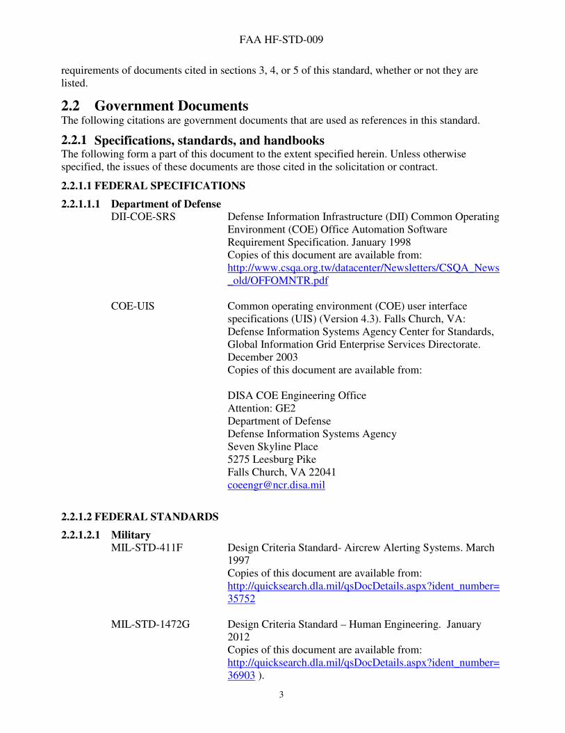
2.2 Government Documents The following citations are government documents that are used as references in this standard.
2.2.1 Specifications, standards, and handbooks The following form a part of this document to the extent specified herein. Unless otherwise specified, the issues of these documents are those cited in the solicitation or contract.
2.2.1.1 FEDERAL SPECIFICATIONS
2.2.1.1.1 Department of Defense
DII-COE-SRS Defense Information Infrastructure (DII) Common Operating Environment (COE) Office Automation Software Requirement Specification. January 1998 Copies of this document are available from: http://www.csqa.org.tw/datacenter/Newsletters/CSQA_News_old/OFFOMNTR.pdf
COE-UIS Common operating environment (COE) user interface specifications (UIS) (Version 4.3). Falls Church, VA: Defense Information Systems Agency Center for Standards, Global Information Grid Enterprise Services Directorate. December 2003 Copies of this document are available from:
DISA COE Engineering Office Attention: GE2 Department of Defense Defense Information Systems Agency Seven Skyline Place 5275 Leesburg Pike Falls Church, VA 22041 [email protected]
2.2.1.2 FEDERAL STANDARDS
2.2.1.2.1 Military
MIL-STD-411F Design Criteria Standard- Aircrew Alerting Systems. March 1997 Copies of this document are available from: http://quicksearch.dla.mil/qsDocDetails.aspx?ident_number=35752
MIL-STD-1472G Design Criteria Standard – Human Engineering. January 2012 Copies of this document are available from: http://quicksearch.dla.mil/qsDocDetails.aspx?ident_number=36903 ).
FAA HF-STD-009
4
2.2.1.2.2 Non-Military Federal Agency
DOT/FAA/HF-STD-001 Human Factors Design Standard. Chapter 8: Computer-Human Interface. May 2003 Copies of this document are available from https://www.hf.faa.gov/HFPortalNew/standards.aspx#gsc.tab=0
DOT/FAA/HF-STD-002 Standard Practice: Baseline Requirements for Color Use in Air Traffic Control Displays. April 2007 Copies of this document are available from: https://www.hf.faa.gov/HFPortalNew/standards.aspx#gsc.tab=0
DOT/FAA/HF-STD-003 Standard Practice: Alarms and Alerts in the Technical Operations Environment. August 2009 Copies of this document are available from: https://www.hf.faa.gov/HFPortalNew/standards.aspx#gsc.tab=0
DOT/FAA/TC-08/15 Moving Toward an Air Traffic Control Display Standard: Creating a Standardized Color Palette for Terminal Situation Displays. December 2008 Copies of this document are available from: http://www.tc.faa.gov/its/worldpac/techrpt/tc0815.pdf
NASA-STD-3001 NASA Space Flight Human-system Standard. Volume 2: Human Factors, Habitability, and Environmental Health. October 2011 Copies of this document may be found at the website of the Technical Library located at the William J. Hughes Technical Center: http://www.faa.gov/about/office_org/headquarters_offices/ang/offices/tc/library/
29CFR 794d Section 508 of the Rehabilitation Act of 1973, as amended. http://www.section508.gov/Section-508-Of-The-Rehabilitation-Act
36CFR 1194 Electronic Information Technology Accessibility Standards http://www.gpo.gov/fdsys/granule/CFR-2011-title36-vol3/CFR-2011-title36-vol3-part1194/content-detail.html

FAA HF-STD-009
5
2.2.1.3 FEDERAL HANDBOOKS
2.2.1.3.1 Military
2.2.1.3.2 Non-Military Federal Agency
DOE-HDBK-1140-2001 Human factors/ergonomics handbook for the design for ease of maintenance. February 2001 Copies of this document may be found at the website of the Technical Library located at the William J. Hughes Technical Center: http://www.faa.gov/about/office_org/headquarters_offices/ang/offices/tc/library/
2.2.2 Other government documents, drawings, and publications The following other government documents, drawings, and publications form a part of this document to the extent specified herein. Unless otherwise specified, the issues of these documents are those cited in the solicitation or contract.
2.2.2.1 Military
2.2.2.2 Non-Military Federal Agency DOT/FAA/AM-07/10 Developing the Federal Aviation Administration’s
requirements for color use in air traffic control displays. May 2007 Copies of this document are available from http://www.dtic.mil/cgi-bin/GetTRDoc?AD=ADA467708
2.3 Non-government publications ASTM International (American Society for Testing and Materials)
ASTM F 1166-07 Standard Practice for Human Engineering Design for Marine Systems, Equipment, and Facilities. 2007 Copies of this document are available from: http://www.astm.org/Standards/F1166.htm
Human Factors and Ergonomics Society No Identifier Ahlstrom, U., & Arend, L. (2005). Color usability on air
traffic control displays. In the Proceedings of the Human Factors and Ergonomics Society 49th Annual Meeting (pp. 93-97). Santa Monica, CA: Human Factors andErgonomics Society.Copies of this document are available from:http://www.hf.faa.gov/hfportalnew/Search/DOCs/ahlstrom_arend_2005.pdf
Gantthead.Com IT Project Management No Identifier User interface standards for GUI screen design
(Gantthead.Com web document). 2007 Copies of this document are available from: http://www.gantthead.com
FAA HF-STD-009
6
2.4 Order of Precedence In the event of a conflict between the text of this document and the references cited herein, the text of this document takes precedence. Nothing in this document, however, supersedes applicable laws and regulations unless a specific exemption has been obtained.
3 Definitions
3.1 Definitions Abbreviation - Any shortened form or abridgment of a word, expression, or phrase used to conserve space or time, including initializations, contractions, and acronyms.
Accelerators - Keyboard commands that can be used instead of pointing and clicking on menu options. They are indicated by underlining the proper character and placing the keyboard alternative in parenthesis after the option (e.g., Bold (Ctrl+B)).
Acquiring agency – The agency responsible for acquisition, in this case the agency requesting the development of the GUI.
Active Help – A form of Help that senses an inappropriate entry and interrupts the task to ask users what they are attempting, and if they are sure they want to complete the operation they have just initiated. Depending upon the user response to the question, active Help then suggests the correct action.
Advice - An interactive, context-sensitive “Help” source that indicates what entry to make at the current location in the application, the required keystroke(s), or which steps to take to complete the task.
Advisory - A signal that indicates a safe or normal configuration, condition of performance, or operation of essential equipment or attracts attention and imparts information for routine action purposes.
Alarm – A signal that indicates that the value of a monitored parameter, component, system, or function is outside the specified acceptable range, and immediate action is required to prevent loss of life, equipment damage, or disruption of National Airspace System (NAS) operations.
Alert – A signal that indicates the existence of a condition requiring immediate attention but not immediate action. An alert signal indicates that an operational status or a condition status of an infrastructure resource has degraded or failed, or the resource functions may degrade or fail if action is not taken as soon as practicable.
Alert – A signal that indicates a condition relating to the effective performance of duties. The condition or message requires the specialist or user to take immediate action or indicates that a significant update in information necessary for the effective performance of duties is available.
Alert boxes – Applied to display messages to users to inform them of situations that may require their attention or are possibly dangerous.
FAA HF-STD-009
7
Attributes – Instructions that change the characteristics of a selected item. An example of an attribute is changing text from standard to bold type.
Cascading menu – A type of hierarchical menu in which a submenu is attached to the right side of a menu item. Cascading menus can be added to drop-down menus, pop-up menus, or even other cascading menus.
Caution – See Alert.
Client area (or working area) – The main area of the window that users employ to do their operational or application tasks. It is the area where users make their inputs and receive their outputs.
Combo box – A special type of text box with an attached list of options. Combo boxes allow the user to either select from the given list or type in an alternative response. There are two types of combo boxes, standard and drop-down.
Command entries – A type of control entry that enables the user to initiate a message to the system that will specify desired functions.
Command language – A limited programming language used strictly for executing a series of commands (e.g., Linux, any DOS shells).
Commands – Instructions that cause a device to perform some action.
Contrast – A visual difference between two screen elements produced by differences in their brightness or color.
Contrast ratio – The ratio of a higher luminance to a lower one, e.g,, 3:1.
Control entries – User input for sequence control, such as function key activation, menu selection, and command entry.
Copy – Instructs the computer to copy selected data.
Cursor – A marker on the display screen that indicates the position where the computer expects the next input or will display the next output. The cursor may be positioned automatically or manually.
Database – An organized collection of data.
Data-entry window – A window that contains a set of labeled fields for entering or selecting, changing, and deleting data. It may also contain labeled data display fields, which a user cannot change.
Direct manipulation – When the user controls the interface with the computer by acting directly on objects on the display screen. An object may be an icon, menu option, symbol, button, or dialog box.
FAA HF-STD-009
8
Display sequencing – A means of reducing clutter by displaying a series of partial displays (i.e., a map and a series of overlays) or of displaying data sequentially. It can also be used as a form of animation.
Distractor color – Any color in the field of view that is different from the target color that is under observation.
Drop-down combo box – A combo box that has a down arrow button, and a drop-down list.
Dwell emphasis – When the pointer comes to rest for a predetermined time on a selected object, the computer shows the user which object it perceives the user is about to select.
Ellipses – Visual indicators, such as three dots (...), used to indicate menu options that branch to other submenus distinguishable from menu options that will immediately perform an operation.
Exclusive buttons (option buttons or radio buttons) – Single, two-state choices, which are mutually exclusive from each other.
Function keys – Labeled keys that serve as keyboard short cuts (i.e., F1, F2, F3, or with the function name such as Delete or Insert) by combining in one key the actions of a sequence of individual keys.
Graphic menus (palettes) – A set of unlabeled symbols, typically presented within small rectangles. Symbols may be icons, patterns, characters, or drawings that represent an operation. Palettes are used widely in drawing and painting packages but are commonly found in word processing applications as well.
Grid lines – Horizontal lines, vertical lines, or both, extending from the scale divisions of one or both axes of a graph and intended to aid users in locating and reading data points.
Graphical User Interface (GUI) – A type of user interface that allows users to interact with electronic devices using images rather than text commands. It represents the information and actions available to a user through graphical icons and visual indicators such as secondary notation, rather than employing the typed command labels or text navigation that are used in text-based interfaces.
Group – On a pull-down menu is any set of menu items between two separators or the whole list if there are no separators on the pull-down menu.
Hard function key – The physical function key on the keyboard.
Hierarchical menu – A series of options or menus that is organized as a multi-level, branching structure in which an option in a higher-level menu is the name of another menu at the next lower level. The options in the lowest level menus are not the names of other menus. They are commands or selectable values, such as color squares on a palette or specific Auto Text choices (e.g., Dear Sir, or To Whom It May Concern).
FAA HF-STD-009
9
Hot spot – A hot spot for a pointer is the precise part of a screen pointer that marks the screen position (area) where an operation on a pointing device will have an effect. For example: the hot spot for a cursor is the selectable area in a display in which a user can place the pointer and successfully select an icon.
Hot keys – A combination of keys (can be a single key but is usually a combination) that, when pressed simultaneously, execute an operation or procedure more quickly than is possible with pointing devices working with a GUI.
Icon – A small picture or symbol serving as a quick, "intuitive" representation of a software tool, function or a data file accessible on the system. When displayed on a computer display screen, icons can be used to navigate and/or control a computer system.
Insertion point – In a GUI, the insertion point is the position where the next characters entered will appear in the display.
Input focus – The notion that only one window and usually only one object in a window at a time is capable of accepting input from a pointing device or the keyboard.
Keyboard accelerator – A key or simultaneous combination of keys that a user can type to select an option in a menu without having to display the menu.
Keyboard lockout – A state determined by an application in which the application does not accept input from the keyboard.
Marqee-select – refers to the act of opening a selection outline in a display and moving and resizing the selection outline to embrace and thereby select a desired set of graphic objects.
Menu – A list of options from which a user makes a selection or selections.
Menu bar – A narrow panel, usually at the top of a computer screen in menu-based computer systems that continually displays the highest-level menu options available for selection by the user. The options on a menu bar are usually the names of other menus.
Message window (message box) – A secondary window that provides users with non-critical information, progress information about lengthy processes, alerts to unusual events, and/or alarms (warnings) of potential dangers or service interruptions. Message windows may be modal or modeless.
Minimize – An operation that reduces a window’s presence into a standby icon button on the information line at the bottom of the screen.
Mnemonic – A single letter that a user can type to select an option in a menu.
Modal window – A window with which a user must interact before being able to interact with any other windows. A user cannot interact with other windows as long as the modal window is displayed.
FAA HF-STD-009
10
Modeless window – A window that allows a user to interact with other windows.
Navigation keys – Several keys such as Home, End, Page Up, Page Down, and the arrow keys, that are dedicated to keyboard navigation.
On-line Help – Primarily an interactive, context-sensitive source of information that can prompt a user on what entry to make at the current location in an application, what keystrokes are required, or what steps are required to complete a task. On-line Help is a form of on-line documentation and reference information.
Option – One of the selectable items in a menu.
Option buttons (exclusive buttons or radio buttons) – Single, two-state choices, which are mutually exclusive from each other.
Outline selection – An extended form of drag selection that is useful for graphical objects when normal drag selection conflicts with moving objects with the mouse.
Paging – The process of scrolling through data one page at a time.
Palettes (graphic menus) – A set of unlabeled symbols, typically presented within small rectangles. A palette is an effective ways of allowing users to access options. Palettes can be used in selecting icons, patterns, colors, characters, or drawings. They allow the user to select an action or attribute from a group of icons fixed in a window. Palettes can be fixed or floating.
Panes – The separate viewing areas in a split window.
Panning – An orientation of display framing in which a user conceives of the display frame as moving over a fixed array of data.
Parallax – A perceived displacement in the apparent position of an object when viewed from different points of view.
Passive Help – A form of help that responds to user requests for information. The information may be in the form of on-line system documentation, such as a user's guide or a list of functions performed by pressing a combination of keys.
Pointer – A symbol displayed on the screen that is controlled by a pointing device. Its shape may change depending on the function that is invoked at a particular moment or its location on the screen.
Pointing device – A non-keyboard device that allows a user to navigate rapidly around the screen and to specify and select objects for manipulation and action.
Pop-up menus – Menus that only appear on user demand. They are often associated with a particular object on a display (i.e., a pop-up menu listing acceptable command options close to the immediate work area). Because pop-up menus are not displayed all of the time, they do not take up valuable screen space. They provide an efficient way to access commands because they eliminate

FAA HF-STD-009
11
the need for the user to navigate to a menu bar or control bar. A pop-up menu typically contains 5 to 10 options presented in a vertical list.
Primary window – A top or high-level window in an application. It is the main location for user interaction and functions independent of other primary windows in the application.
Pull-down menu – A menu associated with an option on a menu bar that appears when a menu bar option is selected.
Query – The process of specifying, locating, and retrieving data matching specified database characteristics.
Radio buttons (exclusive buttons or option buttons) – Single, two-state choices, which are mutually exclusive from each other.
Saturation – A color's vividness, i.e., its difference from white.
Save – An operation that triggers the computer to save the data.
Secondary notation – refers to the set of visual cues that make a formal notation easier to read.
Scrolling – A method used to move through the contents of a window or list in a dialogue box using the scrollbar or scroll arrows.
Scrolling menu – A menu usually containing many options that do not display all options at once. It includes a scroll bar that permits the sequential display of all options. Scrolling menus are also called list boxes and scrolling lists.
Secondary window – A window that is displayed from within a primary (parent) window or another secondary (child) window.
Selection – The action a user makes to choose a menu option. Selection may be accomplished by pointing, typing, or pressing a function key.
Serif – The small cross stroke at the end of the main stroke of the letter.
Slider – A control used to set a value and give a visual indication of the current setting or value in the full context of its available range of possible values.
Soft function key – An area on the screen that represents a function key.
Specular glare – The mirror-like reflection of light striking a surface from an oblique angle.
Spin button (also known as a spin box) – A variation of the scrolling menu or list. A spin button is made up of a text box and two arrows and displays a sequence of mutually exclusive choices.
Spin box (also known as a spin button) – A variation of the scrolling menu or list. A spin box is made up of a text box and two arrows and displays a sequence of mutually exclusive choices.

FAA HF-STD-009
12
Split bar – The divider placed across the middle of the window that separates the panes.
Split box – A rectangular indicator located inside the scrollbar of a split window or immediately above the scrollbar of a split-able window. Note, however, that in some rules, the split box is called the split bar.
Stacking – The stringing together of commands so that they can all be executed with a single command.
Standard combo boxes – A special type of text box that includes a standard list of options with all options visible to the user.
Status bar – A special type of message bar used to present information about the current status of the application.
Syntax – The set of rules governing the language of a command language. Examples would be rules about the order in which parts of a command occur or rules about punctuation in commands.
Tear-off menu – A menu that can be removed from the menu bar and moved to another location on the screen where it can remain on display. Tear-off menus are also called “tacked” or “pushpin” menus.
Text boxes – Edit controls into which the user types information. Most text boxes are one line tall, but applications can also use multi-line text boxes.
Text frame – A field that allows a user to enter text. This is a dynamic form of an edit field and should not be confused with the text box. Although text frames are generally rectangular, other shapes may also be used.
Toggled menu options – Options that are used to issue commands as a binary selection of one of two opposite commands.
Utility window – A supplementary window that provides the users with additional tools or controls such as a tool palette or a set of text attributes.
Warning – A signal that indicates the existence of a hazardous condition requiring immediate action to prevent loss of life, equipment damage, or a service interruption.
Working area (or client area) – The main area of the window that users employ to do their operational or application tasks. It is the area where users make their inputs and receive their outputs.
FAA HF-STD-009
© Reprinted, with permission, from the F1166-07(2013) Standard Practice for Human Engineering Design for Marine Systems,
Equipment, and Facilities, copyright ASTM International, 100 Barr Harbor Drive, West Conshohocken, PA 19428.
13
4 General Requirements This section covers general requirements that are applicable to various aspects of the visual display of information, cognitive performance support, task performance support, standardization, and interface control characteristics.
4.1 Graphical user interface screen design The GUI screen design refers to the way information is arranged and presented on a display screen.
4.1.1 Simplicity GUI designers shall focus on presenting the user with essential information required to conduct operational tasks in an organized, uncluttered, and uncomplicated manner. Additionally, the dynamic interaction shall be simplified.©
4.1.2 Intuitive design GUI interaction designs shall reflect established standard procedures and user expectations in order to maintain acceptable performance and limit human errors. The goal for effective interface design is for the user to be able to anticipate system responses and operate/navigate a system in a timely fashion and with minimal training.©
4.1.3 Task-oriented design The GUI design shall reflect formal analyses of system functions and tasks to ensure that the interface provides all of the functionality and information required for the user to perform tasks. Critical to providing task-oriented design is limiting the interaction (both user supplied actions to the system and information fed to the user) to information essential for the specified task.©
4.1.4 Consistency of content GUIs shall present content in a consistent, standardized manner.
4.1.5 Consistency of data display GUI data display selections for wording, format, and style shall be consistent with the requirements for data entry and control.
4.1.6 Directly usable form The GUI shall present information to a user in a directly usable form; the user shall not have to decode, interpret, transpose, compute, interpolate, or mentally translate data into other units, number bases, or languages.©
4.1.7 Data display context The user shall not have to rely on memory to interpret new data; each data display shall provide needed context, including recapitulating prior data from prior displays as necessary.©

FAA HF-STD-009
© Reprinted, with permission, from the F1166-07(2013) Standard Practice for Human Engineering Design for Marine Systems,
Equipment, and Facilities, copyright ASTM International, 100 Barr Harbor Drive, West Conshohocken, PA 19428.
14
4.1.8 Minimal information density GUI developers shall keep information density in the display to the minimum necessary for critical task sequences. A minimum of one-character space shall be left blank vertically above and below critical information, with a minimum of two character spaces left blank horizontally before and after.©
4.1.9 Displayed information content The content of information displayed to a user shall facilitate the user’s performance of the intended mission, and shall be limited to that necessary to perform needed actions or to make the necessary decisions. Information requirements shall be traceable to a task analysis.
4.1.10 Displayed information precision The GUI shall present information within the limits and precision required for specific user actions or decisions.
4.1.11 Screen design and content An analysis of user tasks should drive the design of the display screen layout, including display partitioning, paging, scrolling, and inter-frame considerations.©
4.1.12 Vocabulary The GUI shall use task-oriented and familiar wording for all non-editable, presented text.
4.1.13 Redundancy of displayed information GUI presented information shall avoid redundancy unless required to achieve reinforcement of information.
4.1.14 Duration of displayed information For signals or displays that frequently or consistently change their outputs, the information displayed shall be displayed for a sufficient duration to be reliably detected under expected user workload and operational environment.©
4.1.15 Legibility The GUI shall present information legibly, anticipating all reasonable viewing conditions and with due consideration given to ambient lighting and viewing distance.©
4.1.16 Units of measure Displays of quantitative information shall include units of measure.©
4.1.17 Image polarity If the ambient illumination in the vicinity of the display is 540 lux or greater, dark characters and symbols on a light background shall be used rather than light characters on a dark background.
4.2 Input conventions Selection of an input device shall be based upon an analysis of the tasks required by the user.
4.2.1 Keyboard use Arrangements of pushbutton in the form of keyboards shall be used when alphabetic, numeric, or special function information is to be entered into a system.©
FAA HF-STD-009
© Reprinted, with permission, from the F1166-07(2013) Standard Practice for Human Engineering Design for Marine Systems,
Equipment, and Facilities, copyright ASTM International, 100 Barr Harbor Drive, West Conshohocken, PA 19428.
15
4.2.2 Touchscreen use
4.2.2.1 When to use Touchscreen control may be used to provide an overlaying control function to a data display where direct visual reference access and optimum direct control access are desired.
a. Touchscreens are appropriate for interactions involving the selection of devices or targets on position displays (e.g., radars), arrangement diagrams, piping diagrams, discrete-function controls, or opening/closing valves.
b. Touchscreens may be used to complete intermittent actions such as gross cursor navigation and communication panel selection.©
4.2.2.2 When not to use A touchscreen shall not be used if:
a. The interface will be used to enter large amounts of data frequently. b. It is the sole input means and system movement or vibration degrades user performance
below the level required for mission accomplishment. c. It is to be used for frequent actions over an extended duration of time (e.g., typing on a
virtual keyboard, continuous target selection). This does not apply to small hand-held devices.
4.2.3 Use of pointing devices
4.2.3.1 Pointing device selection and capabilities The pointing device selected for an application should be the one that most appropriately meets the application requirements and is most cost effective. When present, a pointing device shall be capable of the following:
a. Moving a pointer on the screen, b. Selecting objects on which the pointer is placed, and c. Drag and drop operations.
Discussion: Additional information concerning the use of pointing devices may be found in the sections concerning navigation, controls, interaction, and windows.©
4.2.3.2 Pointing device activation The selection or activation process should be invoked by pressing a button on the pointing device. If the device has only one button, that button should provide the “select” function. If the device has two buttons, the left button should provide the “select” function and the right button should access a “menu” function. The system shall provide users with the ability to reverse the left-right operation functions of the buttons.©
4.3 Text/data entry/display
4.3.1 Data entry function design Data entry functions shall be designed to establish consistency of data entry transactions, minimize input actions and memory load on the user, ensure compatibility of data entry with data display, and provide the user flexible control of data entry.©

FAA HF-STD-009
© Reprinted, with permission, from the F1166-07(2013) Standard Practice for Human Engineering Design for Marine Systems,
Equipment, and Facilities, copyright ASTM International, 100 Barr Harbor Drive, West Conshohocken, PA 19428.
16
4.3.2 Avoidance of complex formats Complex formats and embellishments that do not convey useful information shall be avoided.
4.3.3 Format consistency across systems Formats shall be consistent within a system and across systems.
4.3.4 Format consistency within tasks The same format shall be used for input and output within a task.
4.3.5 Computer controlled formats Data, text, and graphical formats shall be computer controlled, not user controlled.
4.3.6 Format appropriate with training level The format shall be appropriate to the user's level of training and experience.
4.3.7 Data item length The length of individual data items shall be no more than necessary to accomplish the task.
4.3.8 Data manipulation The system shall enable the user to manipulate data without concern for internal storage and retrieval mechanisms of the system.©
4.3.9 Undo capability Users shall be able to reverse a previous action or actions with an Undo command.
4.3.10 Text entry limits Text entry shall be possible only when the text cursor is visible in a location that can accept text entry.
4.3.11 Display of current position The current position in the document (i.e., the current page or line number) shall be displayed in a consistent location, such as in the window's message area.
4.3.12 Adequate text entry area The GUI shall provide an adequate screen-working area that permits users to enter and edit text.
4.3.13 Hot key provision Hot keys shall be provided for more repetitive functions.
4.3.14 Consistent wording and structure The wording and grammatical structure of displayed data and labels shall be consistent throughout an application and related applications.
4.3.15 Stationary text Unless triggered by user action, text information shall be stationary on the screen, not scrolled continuously.
4.3.16 Distinctive appearance Text entered by a user shall be clearly distinguishable from system-supplied text that also appears on the screen.
FAA HF-STD-009
© Reprinted, with permission, from the F1166-07(2013) Standard Practice for Human Engineering Design for Marine Systems,
Equipment, and Facilities, copyright ASTM International, 100 Barr Harbor Drive, West Conshohocken, PA 19428.
17
4.3.17 Text display (wysiwyg) The user shall be able to display text as it will appear in print, including underlining, boldface, subscript, superscript, special characters, special symbols, and different styles and sizes of type.
4.3.18 Text printing options In printing text, users shall be able to select among available output formats (e.g., line spacing, character size, margin size, heading, and footing) and to specify the pages of a document to be printed.©
4.4 Form-based text/data entry/display Form fill-in as a means of data entry is appropriate if some flexibility is needed (i.e., the inclusion of optional as well as required items), if users will have had moderate training, or if computer response time is slow. The form fill-in interaction style is intended for a different set of users than command language; namely non-expert users. Form fill-in interfaces can be especially useful for routine, clerical work or for tasks that require a great deal of data entry. The form fill-in style is also known as “fill-in-the-blanks”.©
4.4.1 Form identification Each form shall have a title located at the top of the form.
4.4.2 Format and content consistency The format and content of displayed forms should follow, in every major parameter, the paper form it is intended to represent.©
4.4.3 Field data entry The displayed form shall require a response for every data entry field. Leaving a field blank, when data entry is not necessary, shall require an explicit action (i.e., using the Tab or Enter keystrokes to advance the cursor.)
4.4.4 Consistency within and among applications Forms, labels, fields, messages, and instructions that appear on different displays shall be as consistent as possible within an application and among related applications.
4.4.5 Distinctiveness of fields Fields or groups of fields shall be separated by spaces, lines, or other delineation cues. Required fields shall be distinguished from optional fields.©
4.4.6 Form fill-in field labels Field labels shall be distinctively presented such that they can be distinguished from data entry. Labels for data entry fields shall incorporate additional cueing of data format where the entry is made up of multiple inputs (e.g., DATE (MM/DD/YYYY): _ _ / _ _ / _ _ _ _).©
4.4.7 Cursor positioning The following requirements apply to cursor positioning and movement through a form.
FAA HF-STD-009
© Reprinted, with permission, from the F1166-07(2013) Standard Practice for Human Engineering Design for Marine Systems,
Equipment, and Facilities, copyright ASTM International, 100 Barr Harbor Drive, West Conshohocken, PA 19428.
18
4.4.7.1 Cursor positioning for initial data entry A displayed cursor shall be positioned, by the system, at the first data entry field when the form is opened initially.©
4.4.7.2 Next field advance Using the tab key shall advance the cursor to the next data entry field when the user has completed entry of the current field.©
4.4.7.3 No-entry protected areas No-entry (protected) areas of the display shall be designated as such and made inaccessible to the user via the cursor.©
4.4.7.4 Automatic next field advance Upon reaching the end of the current field, the GUI shall automatically proceed to the next field.
4.4.8 Preformatted forms Where formats conform to a defined standard or are predictable in other ways, pre-stored forms
shall be provided to aid users.
4.4.9 Group related information Displayed forms shall be arranged such that related items are grouped together.©
4.4.10 Missing data indications When required data entries have not been entered, the omission shall be indicated to the user and either immediate or delayed entry of the missing items shall be allowed. However, a delayed entry should be avoided, when possible. If necessary, the user shall be required to designate the field to indicate that the missing item is delayed, not overlooked.©
4.4.11 Data entry assistance Form filling shall be considered as an aid for composing complex control entries. For example, for a print request, a displayed form should help a user invoke the available format controls.©
4.4.12 Field Help Help shall be provided for fields. Discussion: Help may be provided automatically when the cursor arrives in a field, such as an explanatory message or a menu of acceptable entries. Context sensitive help may be provided in other ways (i.e., an option that offers help on the field that contains the cursor and one that provides help on the field when a user moves the pointer onto the field label and clicks the appropriate button).
4.5 Graphical data entry/display Graphic data displays may be used to present trend information assessments, spatially structured data, time critical information, or relatively imprecise information.
FAA HF-STD-009
© Reprinted, with permission, from the F1166-07(2013) Standard Practice for Human Engineering Design for Marine Systems,
Equipment, and Facilities, copyright ASTM International, 100 Barr Harbor Drive, West Conshohocken, PA 19428.
19
4.5.1 Graphical data consistency Graphics shall be consistent in design, format, and labeling throughout an application and related applications. Example: When graphic data are labeled, the text would appear in a consistent location in relation to the graphic elements.
4.5.2 Labels Displayed graphics shall be clearly labeled.
4.5.3 Reference values When users are required to make comparative evaluations against reference values, the reference values shall be displayed.
4.6 Dynamic information refresh/update
4.6.1 Update rate When a task requires that a user read changing data, individual data items shall be displayed long enough for the user to reliably and accurately read the data. Example: A specialist is remotely monitoring equipment in the field and observing several system parameters that are changing in real time.
4.6.2 Update rate for real time Changing values that the user uses to identify rate of change or to read gross values shall be updated from 2-5 times per second, when the display is in real time.
4.6.3 Alphanumeric data Alphanumeric data that users are required to read reliably and accurately shall not be updated more often than once a second.©
4.7 Coding Coding is used to differentiate between items of information and to call the user’s attention to changes in the state of the system. Coding can be used for critical information, unusual values, changed items, items to be changed, high priority messages, special areas of the display, errors in entry, criticality of command entry, and targets.©
4.7.1 General provisions The following are general provisions for the use of coding to increase information content and impact.
4.7.1.1 Functional use of visual coding Visual coding shall be used for functional, not decorative, purposes.
4.7.1.2 Judicious Use Coding techniques that have strong attention-getting qualities (e.g., color and flashing) should be used judiciously.
FAA HF-STD-009
© Reprinted, with permission, from the F1166-07(2013) Standard Practice for Human Engineering Design for Marine Systems,
Equipment, and Facilities, copyright ASTM International, 100 Barr Harbor Drive, West Conshohocken, PA 19428.
20
4.7.1.3 Consistent coding Coding techniques (e.g., color, shape, location) used to enhance the transfer of information from a display shall be clear, concise, and consistently applied wherever that display is used. Coding should be appropriate for the industry, organization, and culture of the personnel using the display.
4.7.1.4 Special codes Codes that are assigned a special meaning in a display should be defined at the bottom of the display.
4.8 Interaction conventions
4.8.1 Menus A menu is a list of options from which a user makes a selection or selections. An option is one of the selectable items in a menu. Selection is the action a user makes in choosing a menu option. Selection may be accomplished by pointing, by typing, or by pressing a function key. Discussion: The use of menus as an interaction method is widespread, often in conjunction with other methods such as direct manipulation. Menus are usable with little or no training on the part of the user. If the meanings of the options are clear, the user can be guided step-by-step through an application. Menus do have some disadvantages; however, they can slow down an experienced user; they can occupy a considerable amount of display space; and, in complex sequences, users may become lost in the menu structure.©
4.8.1.1 Menu use Menus shall be used for selecting from a set of related options. Menu selection interactive control shall be used for tasks that involve little or no entry of arbitrary data and where users may have relatively little training. It shall also be used when a command set is so large that users are not likely to be able to commit all of the commands to memory.©
4.8.1.2 Menus distinct from other displayed information Menus shall be distinct from the other objects or information on the screen.
4.8.1.3 Consistency in style Menus throughout an application shall conform to a single style of interface (e.g., Microsoft Windows or Macintosh).
4.8.1.4 Consistency in format The GUI shall present menus in a consistent format throughout the system and these shall be available at all times.©
4.8.1.5 Consistency in wording and presentation
When the same menu or option appears in different displays within an application, it shall be consistent in wording and presentation.
4.8.1.6 Option Sequencing Menu selections shall be listed in a logical order, or, if no logical order exists, in the order of frequency of use.©

FAA HF-STD-009
© Reprinted, with permission, from the F1166-07(2013) Standard Practice for Human Engineering Design for Marine Systems,
Equipment, and Facilities, copyright ASTM International, 100 Barr Harbor Drive, West Conshohocken, PA 19428.
21
4.8.1.7 Option Presentation Selection codes and associated descriptors shall be presented on single lines.©
4.8.1.8 Active option presentation The system shall present only menu selection for actions that are currently available.©
4.8.1.9 Instructions Instructions pertaining to menus shall appear in a Help window in a consistent location on the screen.
4.8.2 Queries Query language dialog shall be used for tasks involving unpredictable information retrieval (as in many analysis and planning tasks).©
4.8.2.1 User-centered and natural organization of data
Query languages shall reflect a data structure or organization perceived by users to be natural. If a user supposes that all data about a specific topic are stored in one place, then the query language shall allow such data to be retrieved by a single query, even though the data may be stored in different locations).©
4.8.2.2 Coherency of representation of data organization A single representation of the data organization for use in query formulation shall be established (i.e., the user shall not necessarily need to know if different queries will access different databases over different routes).©
4.8.2.3 Task-oriented queries A user shall be able to specify which data are requested without having to tell the system how to find the data.©
4.8.2.4 Large scale retrieval confirmation When a query results in a large-scale and/ or time-consuming data retrieval, the user shall be notified of the amount of data and/or retrieval time required, and asked to confirm the transaction or take further action to narrow the query before proceeding. (For purposes here, large-scale data retrieval is defined as that amount of data that requires several seconds or more to complete the transfer).©
4.8.2.5 Retrieval interrupt
The user shall be able to interrupt or cancel the data retrieval process at any time.
4.8.2.6 Flexible queries When natural language query is permitted, the system or application shall allow users to employ alternative forms when initiating queries. Example: A system might accept all of the following as equivalent: Update network display within 3 miles. Update network display in a 3-mile radius. Update network display out to 3 miles.
FAA HF-STD-009
© Reprinted, with permission, from the F1166-07(2013) Standard Practice for Human Engineering Design for Marine Systems,
Equipment, and Facilities, copyright ASTM International, 100 Barr Harbor Drive, West Conshohocken, PA 19428.
22
4.8.3 Question and answer dialogs Question and answer (Q&A) dialogs may be used for routine data entry tasks where data items are known and their ordering can be highly structured, where users will have little or no training, and where the computer is expected to have a medium priority response time.©
4.8.3.1 Consistency The format and question-answer procedures shall be consistent throughout an application and related applications.
4.8.3.2 Singular presentation of questions Users shall only be presented with and required to answer one question at a time.©
4.8.3.3 Recapitulating prior answers When a series of computer-posed questions are interrelated, answers to previous questions shall
be displayed when those will provide context to help a user answer the current question.©
4.8.4 Command language
4.8.4.1 Command language applicability Command language interactive control may be used for tasks that involve a wide range of user inputs and where a user with familiarity with the system can take advantage of the flexibility and speed of this control technique.©
4.8.4.2 User viewpoint A command language shall reflect the user’s point of view (as defined in the task analysis) such that the commands are logically related to the user’s conception of what is being done.©
4.8.4.3 Familiar wording Words used in command language dialog shall be chosen to reflect the user's point of view and
shall correspond to the user's operational language.
4.8.4.4 Standardization of commands and abbreviations All commands and their abbreviations, if any, shall be standardized within and across other systems that the user is expected to operate.©
4.8.4.5 Command entry A command language shall be designed so that users can enter commands in terms of desired functions without concern for internal computer processing, storage, and retrieval mechanisms.
4.8.4.6 Command abbreviations The user shall be permitted to enter the full command name or an abbreviation for any command of more than five characters.©
4.8.4.7 Command syntax Command language syntax shall be consistent within an application and across related applications. The syntax of a command language is the set of rules governing the language (i.e., rules about the order in which parts of a command occur or rules about punctuation in commands – options in DOS are preceded by a backslash).

FAA HF-STD-009
© Reprinted, with permission, from the F1166-07(2013) Standard Practice for Human Engineering Design for Marine Systems,
Equipment, and Facilities, copyright ASTM International, 100 Barr Harbor Drive, West Conshohocken, PA 19428.
23
4.8.4.8 Command punctuation The command language shall contain a minimum of punctuation or other special characters.©
4.8.4.9 Command name distinctiveness Command names shall be distinctive from one another.©
4.8.4.10 Command content distinctiveness Words in a command language shall be distinctive from one another, emphasizing significant differences in function.
4.8.4.11 Consistent wording of commands All words and their abbreviations in the command language shall be consistent in meaning and spelling from one transaction to another and from one task to another.
4.8.4.12 Command language complexity The command language shall be programmed in layers of complexity such that the basic layer will allow the inexperienced user to control a transaction. As the user’s skill increases, the command language shall allow for skipping from basic to more advanced layers to meet the user’s current skill level.©
4.8.4.13 Organization of command language features The command language shall be designed so that its features (functions) are organized in groups for ease of learning and use. Example: Enable the user to display the next set of received messages with a simple command (e.g., use Next) instead of the user needing to enter the complete command to retrieve a message that might include specification of message, message list, format, and output device.
4.9 Interrupt capabilities
4.9.1 User interruption of transactions A system or application shall permit a user to interrupt or terminate the current transaction.
4.9.2 Distinct interrupts Each type of interruption shall have a separate control option and a distinct name.
Example: The following types of interruptions may be provided: Cancel, Escape, Back, Restart, Abort, Stop, Pause-Continue, and Suspend.
4.9.3 Data integrity in the face of user interruption User interruptions shall not change or remove stored or entered data, with the exception of the Cancel interrupt.
4.9.4 Back (or Go-back) provision A Back or Go-back option shall be provided to return the display to the previous transaction without altering prior completed transactions.
FAA HF-STD-009
© Reprinted, with permission, from the F1166-07(2013) Standard Practice for Human Engineering Design for Marine Systems,
Equipment, and Facilities, copyright ASTM International, 100 Barr Harbor Drive, West Conshohocken, PA 19428.
24
4.9.5 Cancel (or Undo) provision When appropriate, a system or application shall provide a Cancel or Undo option that will erase changes just made by a user and restore the current display to its previous state.
4.9.6 Reversing Undo provision The user shall be able to reverse the effect of the last Undo command either by selecting the Undo command a second time or selecting a Redo command.
4.9.7 Multi-level Undo provision The user shall be able to (a) stop the control process at any point in a sequence as a result of an indicated error or as an option and (b) return easily to previous levels in multi-step processes in order to nullify an error or to affect a desired change.©
4.9.8 End, Exit, or Stop provisions When appropriate, a system or application shall provide an End, Exit, or Stop option to conclude a repetitive transaction sequence.
4.9.9 Pause and continue (resume) provisions When appropriate, a system or application shall provide Pause and Continue options that will interrupt and later resume, respectively, a transaction sequence without any change to data entries or control logic for the interrupted transaction.
4.9.10 Indicating pause status When a Pause option is provided and selected, the system or application shall provide an indication that the transaction sequence has been halted.
4.9.11 Restart (or Revert) When appropriate, a system or application shall provide a Restart (or Revert) option that will cancel entries made in a defined transaction sequence and will return the user to the beginning of the sequence.
4.9.12 Restart confirmation When a Restart results in the loss of data or changes, the system shall require a user to confirm the action.
4.9.13 Review option When appropriate, a system or application shall provide a nondestructive Review option that will return to the first display in a defined transaction sequence, permitting the user to review a sequence of data entries and make necessary changes.
4.9.14 Suspend option When appropriate, a system or application shall provide a Suspend option that permits a user to preserve the current state of a transaction while leaving the system and to resume the transaction at a later time.
4.9.14.1 Suspended status indication When a system or application provides a Suspend option, it shall display an indication that a transaction has been suspended whenever the option has been selected.
FAA HF-STD-009
© Reprinted, with permission, from the F1166-07(2013) Standard Practice for Human Engineering Design for Marine Systems,
Equipment, and Facilities, copyright ASTM International, 100 Barr Harbor Drive, West Conshohocken, PA 19428.
25
4.9.14.2 Resuming suspended transactions The system shall prompt the user with information on how to resume the suspended transaction (i.e., the user might see: "Press Escape to return to application").
4.10 File management provisions
4.10.1 Saving and retrieving graphic data A quick and convenient means shall be provided for saving and retrieving graphic data.©
4.10.2 Data storing provisions Users shall be able to specify the file names for storing text or graphic data files and be able to view lists of these stored files.©
4.10.3 Protection against exit without saving If the file has not been saved, the GUI shall prompt the user to save file contents when exiting a file.
4.11 Transaction control
4.11.1 Standard procedures for transactions Users shall be provided standard procedures for similar, logically-related transactions based upon an analysis of user tasks.©
4.11.2 User-specified transaction timing When appropriate to task requirements, users shall be able to specify transaction timing. Example: Users might be able to specify when a transaction starts, when it is completed, and the periodic scheduling of repeated transactions.
4.11.3 User-memory load limits The number of mnemonics, codes, special or long sequences, and special instructions that users may need to learn shall be minimized.©
4.11.4 Code recall avoidance Arbitrary codes or codes that are to be recalled by the users shall be avoided.
4.11.5 Transaction sequencing Transaction sequencing shall be dictated by user choices and not by internal computer-processing constraints.©
4.11.6 Alphanumeric code limits When the user must recall alphanumeric codes, the codes shall be limited to five characters.
4.12 Control conventions
4.12.1 Consistent and distinctive Each type of control in an application shall be consistent and visually distinct from other types of controls.
FAA HF-STD-009
© Reprinted, with permission, from the F1166-07(2013) Standard Practice for Human Engineering Design for Marine Systems,
Equipment, and Facilities, copyright ASTM International, 100 Barr Harbor Drive, West Conshohocken, PA 19428.
26
Example: Pushbuttons are consistent and distinct from radio buttons (exclusive button sets).
4.12.2 Distinction from other information objects Controls shall differ in appearance from other text and graphics in an application window.
4.12.3 Control/display relationships Control/display relationships shall be straightforward and explicit.©
4.12.4 Simple operation Control actions shall be simple and direct, whereas potentially destructive control actions shall
require extended user attention (e.g., “Are you sure?” queries).©
4.12.5 Tailorable cursor control Systems using cursors shall provide cursor control capability consistent with user speed and accuracy requirements. Additionally, the user should be able to adjust the sensitivity of the cursor movement to be compatible with the required task. Note: The user’s ability to adjust the sensitivity of the cursor movement shall be provided only where adjustment of this control could not adversely affect the ability to fulfill the mission and complete critical tasks.©
4.13 Window provisions Windows can be either modal or modeless. A modal window is an information window in which a user must complete an action before being able to interact with other windows. That is, a user cannot interact with other windows as long as the modal window is displayed. When a window is modeless, a user can interact with multiple windows.
4.13.1 Window control features The user shall have the capability to perform the following operations on open windows: move, resize, hide (or minimize), activate, deactivate, scroll, and zoom.©
4.13.2 Basic operations Users should be able to perform the following operations on objects in an information window:
a. Select an object with the pointing device. b. Select an object using the keyboard. c. Move an object to another location in the same window. d. Move an object to a different window. e. Copy an object for placement at a different location within the same window. f. Copy an object for placement in a different window. g. Paste an object previously copied from this or another window. h. Undo/redo the last action.©
4.13.3 Window control access Window controls shall be accessible via a pointing device and a keyboard.©
FAA HF-STD-009
© Reprinted, with permission, from the F1166-07(2013) Standard Practice for Human Engineering Design for Marine Systems,
Equipment, and Facilities, copyright ASTM International, 100 Barr Harbor Drive, West Conshohocken, PA 19428.
27
4.13.4 Window control consistency Window controls, such as “open” and “close” shall operate consistently on all windows.©
4.13.5 Minimal manipulation The amount of manipulation required for window operations (e.g., resizing and moving) shall be minimal.
4.13.6 Task-relevant window content Task-related elements and functions shall be located together in one window, or on one page within the same window if the window includes multiple pages.©
4.13.7 Simple navigation Windows shall be designed so that users do not need to:
a. Switch back and forth between windows or pages when performing a task, or b. Remember information from one window or page while viewing another window or
page.©
4.13.8 Initial window presentation Windows shall be presented initially in a form that is most appropriate for user task performance.©
4.13.9 Limits on window operations Window operations shall be limited when the hardware has limitations. Such limitations include:
a. Small screen size resulting in frequent manipulation of the screen by the user; b. Slow processing speed resulting in slow performance by the computer; or c. Low screen resolution resulting in less effective visual coding, especially for map
graphics, symbols, and icons.
4.13.10 Multiple window display provision When there is a need to view different types of data simultaneously, the user shall be able to display and select separate windows on a single screen.©
4.13.11 Number of allowable open windows The number of allowable open windows shall not compromise system response time. Discussion: Each open window requires system resources in terms of memory and processing speed. A limit on the maximum number of windows that can be effectively opened for each system needs to be predetermined.
4.13.12 Default initial window location Each window shall have a default location at which the window appears when it is first opened. Initial placement should be based on the importance of the information in that window and information in other visible windows that should not be obscured. When a window is first displayed, input focus shall be placed on a default object.©
4.13.13 Consistency in window organization The windows in an application and related applications shall have a consistent organizational scheme for the key elements of the windows.©

FAA HF-STD-009
© Reprinted, with permission, from the F1166-07(2013) Standard Practice for Human Engineering Design for Marine Systems,
Equipment, and Facilities, copyright ASTM International, 100 Barr Harbor Drive, West Conshohocken, PA 19428.
28
4.13.14 Logical information organization Information in windows should be organized in some recognizable, logical, and consistent form to facilitate scanning and assimilation.©
4.13.15 Element relevancy and consistency Individual windows shall contain only those information elements appropriate to the relevant task and the presented elements shall be consistent from window to window throughout the application.
4.13.16 Information grouping in windows Information in a window should be grouped according to principles obvious to the user (e.g., mission, task, system function, or sequence) based on the user’s requirements when performing an ongoing task.©
4.13.17 Graphical element alignment Related graphics in a window shall be aligned unless position is intended to indicate a spatial or functional relationship.©
4.14 General operability and reliability
4.14.1 Graphical user interface adequacy and response The GUI shall provide adequate information, and respond within the required time limits with sufficient detail and precision to ensure mission accomplishment.©
4.14.2 Minimized task complexity The GUI shall minimize user task complexity, simplify control inputs to the extent possible, particularly for tasks requiring real-time responses, and permit logical task completion with a minimum number of control actions.©
4.14.3 Minimal user interrupts A system or application shall interrupt a user only when necessary to prompt the user for a response, to provide essential feedback, or to inform the user of errors.
4.14.4 Notice of activation A system function shall not be activated without notice to the user.
4.14.5 User action/entry acknowledgement Every user action shall result in an acknowledgement response from the system.
4.14.6 Error management provisions
4.14.6.1 Easy error correction Where users are required to enter data into a system, an easy means shall be provided for correcting erroneous entries, including correcting individual errors without requiring the user to reenter correctly entered commands or data elements.©
4.14.6.2 Appropriate response to all control entries The GUI shall provide an appropriate response for all possible control entries, correct and incorrect.
FAA HF-STD-009
© Reprinted, with permission, from the F1166-07(2013) Standard Practice for Human Engineering Design for Marine Systems,
Equipment, and Facilities, copyright ASTM International, 100 Barr Harbor Drive, West Conshohocken, PA 19428.
29
Example: Selection of an incorrect function key may result in a message listing the appropriate selections.
4.14.6.3 Error detection A capability shall be provided to detect and correct errors after keying in a command or data but before entering the information into the system. While it is desirable that errors be detected early, error checking shall occur at logical data entry breaks (i,e. at the end of data fields rather than character by character) to avoid disrupting the user.©
4.14.6.4 Internal software checks User errors shall be minimized by using internal software checks of user entries for validity of item, sequence of entry, completeness of entry, and range of value.©
4.14.6.5 Immediate data correction When a user has completed a data entry transaction and an error is detected, the user shall be able to make corrections directly and immediately.
4.14.6.6 Explicit user action required provision The GUI shall require an explicit user action to reenter corrected material after a user has completed error correction.
4.14.6.7 Consistent reentry or error provision The Enter action for reentry of corrected items shall be the same as the Enter action for the original entry.
4.14.6.8 Error correction acknowledgement All user error corrections shall be acknowledged by the GUI, either by indicating a correct entry has been made or by displaying another error message (i.e., in the event that the error correction attempt was inadequate).©
4.14.6.9 Return to current task on error correction The GUI shall provide an easy means to return to the previous page after error correction.
4.14.6.10 User notice (by the GUI) of destructive actions When a control entry (including log off) results in a change in stored data, procedures, or system operation (particularly if it is not easily reversible), the system or application shall explicitly notify the user of the potential loss of data, and require a confirmation before implementing the action.
4.14.6.11 Limits on the use of the Enter key The Enter key shall not be used for confirmation of destructive actions.
4.14.6.12 Flexible "go back" for error correction The GUI shall allow a user to return to previous steps in a transaction sequence in order to correct an error or make any other desired change.©
4.14.6.13 Stop control process The user shall be able to stop the control process at any point in a sequence as a result of an indicated error or as an option. The user shall be able to return easily to previous levels in multistep processes to nullify an error or to effect a desired change.©
FAA HF-STD-009
© Reprinted, with permission, from the F1166-07(2013) Standard Practice for Human Engineering Design for Marine Systems,
Equipment, and Facilities, copyright ASTM International, 100 Barr Harbor Drive, West Conshohocken, PA 19428.
30
4.14.6.14 Timeliness of error feedback Error messages and error feedback about the data or control entry shall be provided within 2 to 4 seconds after the user completes the entry in which the error is detected.
4.14.7 Critical entry acknowledgement The system shall require the user to acknowledge critical entries (e.g., Exit, Close, or Delete) prior to their being implemented by the system.©
4.14.8 Alarm/alert signal and control provisions
4.14.8.1 Prompt user attention/action
Each alarm or alert should signal user attention. Each alarm should prompt user action.
4.14.8.2 Convey nature of problem Alarm and alert messages shall concisely convey the nature of the problem as well as the specific subsystem or location of the problem.
4.14.8.3 Standard syntax A standard syntax is desirable for all messages, but shall be subordinate to a clear statement of the problem.
4.14.8.4 No disabling of alarm controls Alarm and alert system control design shall not allow controls to be altered or disabled.
4.14.8.5 Dimming of alarm/alert indications The display shall not be dimmed to such a level that would make the alarm or alert message unreadable.
4.14.8.6 Distinctive controls Alarm and alert system controls should be distinctively coded for easy recognition.
4.14.8.7 Consistent layout Each set of alarm and alert subsystem controls should have the functions in the same relative locations.
4.14.8.8 Distinctive and consistent signals Alarm and alert signals and messages shall be distinctive and consistent for each class of events.
4.14.8.9 Easily recognizable signals Alarms and alerts shall be immediately recognizable under all operating conditions, including normal, emergency, and degraded modes.
4.14.8.10 Clear and unambiguous signals Alarm and alert system signals shall be unambiguous, with a clear indication of the cause for the alarm or alert.©
4.14.9 Operability and accessibility provisions for persons with disabilities
4.14.9.1 Section 508 The GUI system shall be in accordance with 36CFR 1194, Electronics and Information
Technology Accessibility Standard, which implements Section 508 of the Rehabilitation Act of
1973, as amended (29CFR 794d).

FAA HF-STD-009
© Reprinted, with permission, from the F1166-07(2013) Standard Practice for Human Engineering Design for Marine Systems,
Equipment, and Facilities, copyright ASTM International, 100 Barr Harbor Drive, West Conshohocken, PA 19428.
31
4.15 Help support facilities On-line Help is an interactive, context-sensitive source of information that can tell a user what entry to make at the current location in an application, what keystrokes are required, or what steps are required to complete a task. On-line Help is a form of on-line documentation and reference information. Discussion: An On-line Help facility may provide any or all of three types of help: advice, active help, and passive help. Advice is an interactive, context-sensitive source of information that indicates what entry to make at the current location in the application, the required keystroke(s), or which steps to take to complete the task. Active help senses an inappropriate entry and interrupts the task to ask users what they are attempting and if they are sure they want to complete the operation they have just initiated. Depending upon the user response to the question, active help then suggests the correct action. Passive help simply responds to user requests for information. The information may be in the form of on-line system documentation, such as a user's guide or a list of functions performed by combinations of keystrokes.
4.15.1 On-line help provision Users shall be provided on-line, context-sensitive help that includes the following: definitions of allowable options, system capabilities, procedures, and ranges of values upon user request. Discussion: On-line Help should include the following components:
a. Memory aids, b. Basic information likely to be of use only to novices, c. Material selected from written documentation, d. Explanations that elaborate on the written documentation, e. Information that might seem obvious but may not be so to all users, f. Step-by-step instructions on how to perform the most common tasks, and g. Instructions for access to outside help.©
4.15.2 Always accessible help facilities A single, standard action (e.g., single keystroke or click on a pointing device) that is always available shall be provided to request help.©
4.15.3 On-line help adequacy The On-line Help shall be capable of providing sufficient references to address anticipated user questions.
4.15.4 Consistent and distinguishable help formats User guidance shall be displayed consistently in a format that is distinguishable from that of other displayed data.

FAA HF-STD-009
© Reprinted, with permission, from the F1166-07(2013) Standard Practice for Human Engineering Design for Marine Systems,
Equipment, and Facilities, copyright ASTM International, 100 Barr Harbor Drive, West Conshohocken, PA 19428.
32
4.15.5 Consistent terminology On-line documentation, off-line documentation, and help instructions shall use consistent terminology.©
4.15.6 Duration of on-line help On-line Help shall remain visible until the user chooses to remove it.
4.15.7 Help search provisions Users shall be permitted to browse and search through On-line Help displays, just as they would through a printed manual, to gain familiarity with system functions and operating procedures.©
4.15.8 Window-level help access On-line Help shall provide the capability to access window-level help through pull-down menus.
4.15.9 Window mode accessibility to help On-line Help shall be available for all window modes. If the default mode of a window permits text editing, and also has a "print preview" mode, help shall cover capabilities/features available in both modes.
4.15.10 Object-level help On-line Help shall provide the capability to access object-level help through a help key.
4.15.11 Focus without activation On-line support shall allow users to establish focus on a certain object without activating that object. This will enable a user to gain functional or descriptive information about an icon or button without activating the object.
4.15.12 Printable instructions The On-line Help instructions shall be printable.
4.15.13 Persistent display of help instructions The On-line Help shall be capable of keeping the help window displayed but inactive while the user executes the instructions provided in the window. This eliminates the need for the user to memorize instructions while completing the inquired task.
4.16 Data communication support
4.16.1 Functional integration Data transmission functions shall be integrated with other GUI information-handling functions. A user shall be able to transmit data using the same computer system and procedures used for general entry, display, and other processing of data.©
4.16.2 Consistent procedures Procedures for preparing, sending, and receiving data and messages shall be consistent from one transaction to another and consistent with procedures for other information-handling tasks.©
4.16.3 Message handling windows Windows intended for sending and receiving electronic messages shall conform to the general criteria and rules for data entry (see 5.3).

FAA HF-STD-009
© Reprinted, with permission, from the F1166-07(2013) Standard Practice for Human Engineering Design for Marine Systems,
Equipment, and Facilities, copyright ASTM International, 100 Barr Harbor Drive, West Conshohocken, PA 19428.
33
4.16.4 Explicit user actions Both sending and receiving messages shall be accomplished by explicit user action.
5 Detailed Requirements This section describes the detailed requirements for the implementation of GUIs within the scope of this Standard.
5.1 Graphical user interface screen implementation Screen design refers to the way information is arranged and presented on a display screen. The designer needs to understand the primary function of the system being developed to provide an effective screen design.
5.1.1 Screen arrangement and user orientation
5.1.1.1 Highlighting When a user is performing an operation on a selected object in a display, that object shall be highlighted. Discussion: In many applications, at least two different methods of selection highlighting can be provided. The first highlighting method occurs when the pointer comes to rest for a predetermined time on a selected object. This is sometimes referred to as dwell emphasis, and it tells the user which object the computer perceives the user is about to select. This highlighting is normally dim white. The second highlighting method occurs when an actual selection has been made and is normally a bright white.
5.1.1.2 Consistent display of context information Information intended to provide a context for the current user-computer interaction shall be displayed consistently for all transactions within an application and among related applications.
5.1.1.3 Distinctive position and format Displayed options, context information, command entry areas, prompts, advisory messages, and other displayed items (e.g., titles and time signals) relevant to transaction control shall be distinctive in location and format.
5.1.2 Labeling
5.1.2.1 Display titles and headers
Each display shall be labeled with a title or header. Titles and headers shall adhere to the following:
a. The title or header shall be unique within the system. b. The title or header shall be positioned at the top center of the page. c. The title or header shall briefly describe the contents or purpose of the page. d. The title or header shall be meaningful enough to be learned and remembered easily. e. At least one blank line shall separate the title or header and the body of the page.©
FAA HF-STD-009
© Reprinted, with permission, from the F1166-07(2013) Standard Practice for Human Engineering Design for Marine Systems,
Equipment, and Facilities, copyright ASTM International, 100 Barr Harbor Drive, West Conshohocken, PA 19428.
34
5.1.2.2 Predictable starting point In any display, the GUI shall make the starting point obvious to the user. Ordinarily, this will be at the upper left part of the screen. Discussion: This might be accomplished by placing the pointer or cursor, if available, at that point or by highlighting the active area of the screen.
5.1.2.3 Organization to facilitate task performance The GUI shall organize and display information in a manner (e.g., chronologically, spatially, alphabetically, according to importance, to suggest a few viable ordering schemes) that is consistent with and facilitates task performance.
5.1.2.4 Page numbering Each page of a multiple-page display shall be labeled to identify the currently displayed page in the context of the total number of pages (e.g., Page 2 of 5).©
5.1.2.5 Use of frames Frames shall be used only when the user will benefit from the simultaneous presentation of two or more groups of information and one or both of the groups requires scrolling to see all of the content.
a. Every display frame shall have a unique identification to provide a reference for use in requesting the display of that frame.
b. Frame identification shall be prominently displayed in the top center of the frame. c. Required frame identification area shall not exceed the size of the frame resized to its
minimum size. d. Frame identification shall be meaningful enough to be learned and remembered easily. e. Frame identification shall describe the content within that frame. f. At least one blank line shall separate the frame identification and the body of the frame.
5.1.2.6 Placement of displayed data according to importance Where some displayed data items are of significant importance or require immediate user response, those items shall be grouped and presented in a highly conspicuous portion of the display.©
5.1.2.7 Alphanumeric labels If letters and numbers are used in a label, the letters and numbers shall be easily distinguishable, avoiding easily confusable letters and numbers (e.g., Z, 2 or, O, 0).
5.1.2.8 Labeling to indicate content Each individual data group or message shall contain a descriptive title, phrase, word, or similar device to designate the content of the group or message. Labels shall perform the following:
a. Be located in a consistent fashion adjacent to the data group or message they describe. The relationship of the label to the group, field, or message being described shall be unambiguous.
b. Be highlighted or otherwise accentuated to facilitate user scanning and recognition. The technique used to accentuate labels shall be different from, and easily distinguished from, that used to highlight or code emergency or critical messages.

FAA HF-STD-009
© Reprinted, with permission, from the F1166-07(2013) Standard Practice for Human Engineering Design for Marine Systems,
Equipment, and Facilities, copyright ASTM International, 100 Barr Harbor Drive, West Conshohocken, PA 19428.
35
c. Be unique and meaningful to distinguish them from data, error messages, or other alphanumerics.
d. Reflect the question or decision being posed to the user, when presenting a list of user options.©
5.1.3 Task-oriented provisions
5.1.3.1 Grouping for relevancy All maintenance displays that are relevant to a particular task should be grouped together and observable by the technician while performing the task.©
5.1.3.2 Separation of operator and maintainer information If maintenance and operator displays must be accessible from the operator's panel, maintenance displays should be grouped and separately accessible from operator displays.
5.1.3.3 Separation of operator and maintainer information exception Operator and maintainer information should not be combined in a single display unless the information content and format are well suited to, and time-compatible for, both users.©
5.1.3.4 Placement for comparison Data fields to be compared on a character-by-character basis shall be positioned one above the other.©
5.1.3.5 Information separation methods
Separation of groups of information shall be accomplished by blanks, spacing, lines, color coding, or other means consistent with the application.©
5.1.4 Consistent content
5.1.4.1 Consistent structure Screens throughout the GUI shall have a consistent structure that is evident to users.
5.1.4.2 Consistent appearance (screen elements) Screen elements such as headers, fields, and labels shall have consistent appearance and relative location throughout the GUI.©
5.1.4.3 Consistent prompt location When applicable, an input prompt shall have a consistent location on all displays throughout the GUI.©
5.1.4.4 Consistent instruction and error message locations Instructions and error messages shall appear in a consistent location on the screen.
5.1.4.5 Consistently distinctive element formats Information element formats shall be consistently distinctive within a display.
5.1.4.6 Consistent data display Data shall be displayed consistently, using standards and conventions familiar to users.
5.1.4.7 Consistent information elements Information elements shall be consistent in word choice, format, and basic style throughout the GUI.
FAA HF-STD-009
© Reprinted, with permission, from the F1166-07(2013) Standard Practice for Human Engineering Design for Marine Systems,
Equipment, and Facilities, copyright ASTM International, 100 Barr Harbor Drive, West Conshohocken, PA 19428.
36
5.1.4.8 Hierarchical access to top-level functions Following a log on screen if applicable, the application GUI shall present to the user an initial display that provides hierarchical access to functions, resources, and applications available to the user, including access to the log on screen, user preference settings, utilities (e.g., a calculator, clock, and calendar), and system-level help.
5.2 Input options
5.2.1 On-screen keyboards Graphical representations of keyboards that appear on video displays and enlist pointing devices or touchscreens shall be designed as following. Discussion: The key configuration and the number of keys are dependent upon the predominant type of information that is to be entered into the system. Keyboard layouts can take several forms that aid entry of such information.©
5.2.1.1 Keyboard Layout options
5.2.1.1.1 Numeric keyboard
The configuration of a keyboard used to enter solely numeric information shall be a 3 X 3 + 1 matrix with the zero digit entered on the bottom row and arranged using the standard calculator format: “789 456 123”. If the keyboard is used primarily for communications, the “telephone” arrangement – with the numerals 1, 2, and 3 in the top row – shall be used.©
5.2.1.1.2 Alphanumeric keyboard
QWERTY keyboards, rather than alphabetical order keyboards, with the numeric keyboard located to the right of the standard keyboard should be provided unless special requirements exist for another type of key arrangement.©
5.2.1.1.3 Multiple keyboards
Systems containing more than one keyboard shall maintain the same configuration for alphanumeric, numeric, and special function keys throughout the system.©
5.2.1.2 Numeric keypads preference Keyboards used in systems requiring substantial numeric data entry shall be equipped with a numeric keypad.©
5.2.1.3 Keyboard/keypad tactile feedback Regardless of layout, tactile feedback shall be provided to inform the user that the key was pressed and that the next operation may be initiated (i.e., spring-loaded keys that click and return to prior height after being depressed and released).©
5.2.2 Touchscreen provisions
5.2.2.1 Touchscreen luminance transmission Touchscreens shall have sufficient luminance transmission to allow the display to be clearly readable in the intended environment and meet the display luminance requirements herein.©
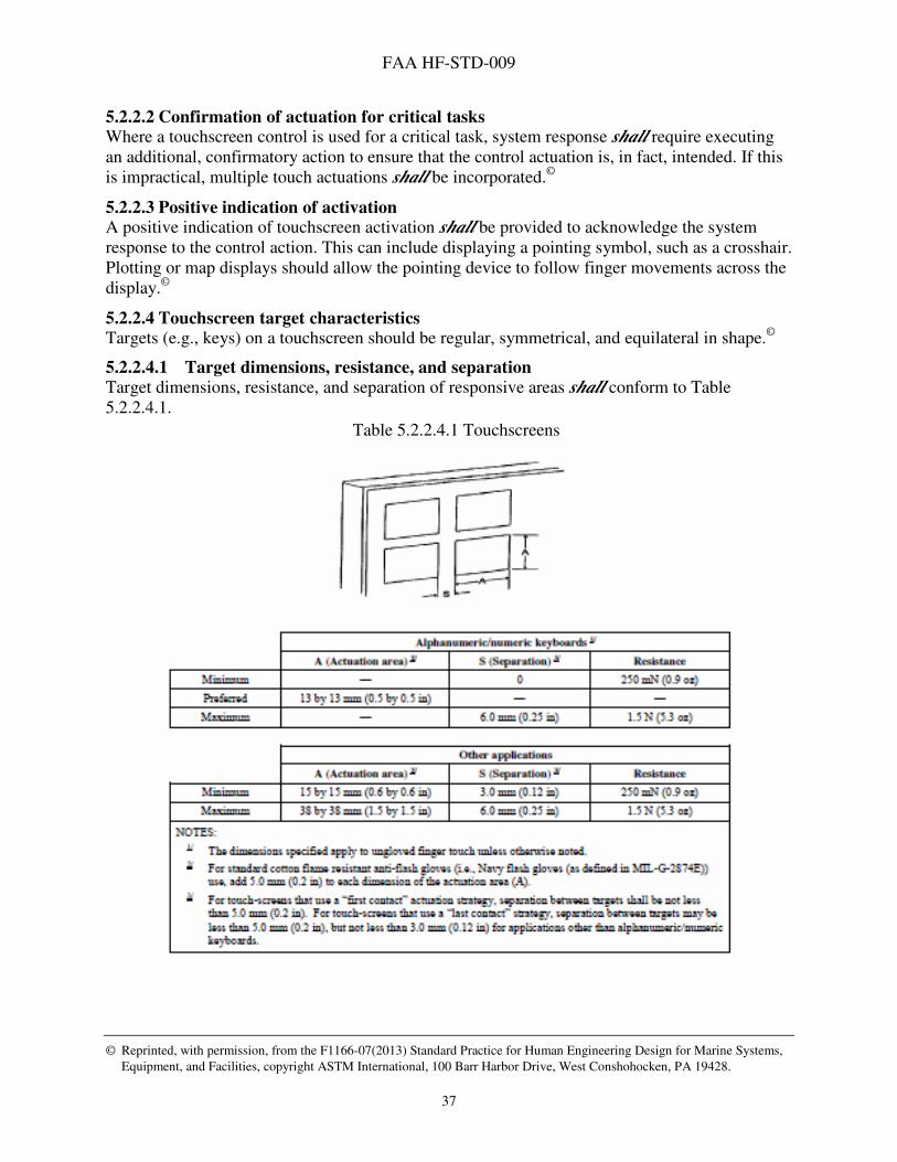
FAA HF-STD-009
© Reprinted, with permission, from the F1166-07(2013) Standard Practice for Human Engineering Design for Marine Systems,
Equipment, and Facilities, copyright ASTM International, 100 Barr Harbor Drive, West Conshohocken, PA 19428.
37
5.2.2.2 Confirmation of actuation for critical tasks Where a touchscreen control is used for a critical task, system response shall require executing an additional, confirmatory action to ensure that the control actuation is, in fact, intended. If this is impractical, multiple touch actuations shall be incorporated.©
5.2.2.3 Positive indication of activation A positive indication of touchscreen activation shall be provided to acknowledge the system response to the control action. This can include displaying a pointing symbol, such as a crosshair. Plotting or map displays should allow the pointing device to follow finger movements across the display.©
5.2.2.4 Touchscreen target characteristics Targets (e.g., keys) on a touchscreen should be regular, symmetrical, and equilateral in shape.©
5.2.2.4.1 Target dimensions, resistance, and separation
Target dimensions, resistance, and separation of responsive areas shall conform to Table 5.2.2.4.1.
Table 5.2.2.4.1 Touchscreens

FAA HF-STD-009
© Reprinted, with permission, from the F1166-07(2013) Standard Practice for Human Engineering Design for Marine Systems,
Equipment, and Facilities, copyright ASTM International, 100 Barr Harbor Drive, West Conshohocken, PA 19428.
38
5.2.2.4.2 Edge dimensions, resistance, separation, and displacement
Dimensions, resistance, separation, and displacement between adjacent edges of the pushbuttons on keyboards shall be per the criteria in Table 5.2.2.4.2. For a given keyboard, these criteria
shall be uniformly met for all individual keys.
Table 5.2.2.4.2 Pushbuttons
5.2.2.5 Touchscreen sensitivity The sensitivity of the touchscreen should be sufficiently high that little resistance or displacement is required to activate the touchscreen (see Table 5.2.2.4.1). Contact with the touchscreen should be adequate to activate the control or input function.©
5.2.2.6 Touchscreen response time System display response time in terms of feedback relating to user’s commands or actions should be evident within 0.25 seconds.©
5.2.2.7 Touchscreen repeat function delay
An initial delay of 500 to 750 milliseconds shall be provided if a repeat delay is necessary. (A repeat delay is an artificial delay programmed into the registration of a response to activation in order to prevent erroneous repetition.) All repeat functions shall display that a repeat request has been initiated.©
5.2.2.8 Parallax and glare
Touchscreen devices shall be mounted to minimize parallax issues and specular glare.©
FAA HF-STD-009
© Reprinted, with permission, from the F1166-07(2013) Standard Practice for Human Engineering Design for Marine Systems,
Equipment, and Facilities, copyright ASTM International, 100 Barr Harbor Drive, West Conshohocken, PA 19428.
39
5.2.2.9 Reach design for touchscreens Reach designs shall meet the following requirements:
a. Touchscreens shall be mounted to ensure that the central 90 percent of the anticipated user population can reach and access all areas of the screen including corners of the display. b. Touchscreens shall be positioned to avoid full arm extension. c. Touchscreens shall be positioned to avoid upward reach. d. Elbow support shall be provided where possible to minimize arm fatigue.
5.2.2.10 Impact on visual display Display characteristics of touch-interactive devices shall not degrade visual quality in a manner that impairs user performance and shall provide sufficient spatial resolution for effective task performance.©
5.3 Text/data entry and display
5.3.1 Data entry and editing
5.3.1.1 Format control A simple and convenient means shall be provided for users to specify the required format control features during data entry/editing (i.e., to specify margins, tab settings, and line spacing).©
5.3.1.2 Predefined formats When text formats must follow predefined standards, the required format shall be provided automatically. Where text formats are a user option, a convenient means shall be provided to allow the user to specify and store for future use the formats that have been generated for specific applications.©
5.3.1.3 Special codes and annotations Where special formatting features are indicated in the text by the use of special codes or annotation, the insertion of special annotation shall not disturb the spacing of the displayed text and shall not disturb formatting of graphs and tables or alignment of rows and columns.©
5.3.1.4 Frequently used text
The capability shall be provided to label and store frequently used text segments (e.g., signature blocks, organizational names, call signs, coordinates) and later to recall (i.e., copy into current text) stored segments identified by their assigned labels.©
5.3.1.5 Positive feedback The system shall provide positive feedback to the user of the acceptance or rejection of a data entry.©
5.3.1.6 Input units Data shall be entered in units that are familiar to the user.©
5.3.1.7 Order and sequence When data fields have a naturally occurring order (e.g., chronological), it shall be reflected in the format organization of the fields.©
5.3.1.8 Single instance data entry The user shall not be required to enter data already available to the software.©
FAA HF-STD-009
© Reprinted, with permission, from the F1166-07(2013) Standard Practice for Human Engineering Design for Marine Systems,
Equipment, and Facilities, copyright ASTM International, 100 Barr Harbor Drive, West Conshohocken, PA 19428.
40
5.3.1.9 Skipping unfilled spaces Users shall not have to move a space at a time over unfilled spaces in variable length fields.©
5.3.1.10 Minimal shift keying The use of key-shifting functions shall be minimized during data entry transactions.©
5.3.1.11 Minimal keying The amount of keying required shall be no more than necessary to accomplish the task.©
5.3.1.12 Auto-entry of leading and trailing zeroes For fixed length fields, a user shall not have to enter leading or trailing zeroes to fill a field. Example: In a fixed length field that requires four digits, if a three-digit number such as 813 is entered into that field, do not require the user to precede the number with a leading zero (e.g., 0813). Likewise, in a fixed length field involving decimal values, do not require the user to enter a value such as 10 with trailing zeroes (e.g., 10.00).
5.3.1.13 Automatic justification of entered data When a user makes an entry that does not fill a variable length field, the entry shall be automatically justified when the cursor leaves the field. Unless otherwise required by processing or display requirements, justification shall be as follows:
a. Alphanumeric input shall be left justified. b. Integer numerical data shall be right justified. c. Decimal numerical data shall be decimal-point justified.©
5.3.1.14 Minimal text length Except for extended text, the length of individual data items shall be kept to minimal length.©
5.3.1.15 Automatic line break An automatic line break (carriage return and line feed) shall be provided when the text reaches the right margin for entering/ editing unformatted text. User override of this feature also shall be provided.©
5.3.1.16 User pacing The user, not the system, shall set the pace.©
5.3.1.17 Form backup, cancel, and restart actions Users shall have the ability to use Backup, Cancel, and Restart actions to edit a form at any time prior to the final completion action.
5.3.1.18 Explicit data entry completion action Data entry shall require an explicit completion action (i.e., depressing an Enter/Return or Save key or “OK” key.)©
5.3.1.19 Explicit form removal action
A form shall not be removed from display until the user takes an explicit completion action such as pressing the Enter key.
FAA HF-STD-009
© Reprinted, with permission, from the F1166-07(2013) Standard Practice for Human Engineering Design for Marine Systems,
Equipment, and Facilities, copyright ASTM International, 100 Barr Harbor Drive, West Conshohocken, PA 19428.
41
5.3.1.20 Data validation Data entries shall be validated by the system for correct format, legal value, or range of values. Where repetitive entry of data sets is required, data validation for each set shall be completed before another transaction can begin.©
5.3.1.21 Editing entries Users shall be able to move the cursor to any unprotected field and change any entry prior to taking a final completion action.
5.3.1.22 Deleting or cancelling data Deleting or cancelling a completed data entry shall require an explicit action, such as the depression of a Delete key. Permanent deletion (in absence of an “Undo” function) of more than one character shall not be allowed without an affirmative response to an “Are you sure?” query. Correcting typographical errors in uncompleted entries shall not require a confirmation action.©
5.3.1.23 Data change Where a user requests changing (or deleting) a data item that is not currently being displayed, the option of displaying the old value before confirming the change shall be presented.©
5.3.1.24 Data editing Easy-to-use, special editing commands such as Move, Copy, and Delete, for adding, inserting, or deleting text/program segments shall be provided.©
5.3.1.25 Editing commands Where editing commands are entered by keying onto the display, the editing commands shall be readily distinguishable from the displayed textual material.©
5.3.1.26 Sequences When text is displayed in a window, sequences of events or steps shall be presented in a logical order.
5.3.1.27 Referents
The referents for pronouns such as "it" and "they" shall be easily identifiable.
5.3.1.28 Abbreviations
5.3.1.28.1 Unambiguous abbreviations
When a system or application uses abbreviations in the user-computer interface, the abbreviations shall be unique, distinct, and unambiguous. An abbreviation is any shortened form or abridgment of a word, expression, or phrase used to conserve space or time. Thus, the term abbreviation includes initializations, contractions, and acronyms.
5.3.1.28.2 Abbreviation consistency
Tech Ops GUIs shall use abbreviations consistent with the Tech Ops Abbreviations Standard currently under development (FAA HF-STD-006A Abbreviations Standard for Technical Operations).
5.3.1.28.3 Abbreviations and system operation
Use of abbreviations shall not add to system operating time.
FAA HF-STD-009
© Reprinted, with permission, from the F1166-07(2013) Standard Practice for Human Engineering Design for Marine Systems,
Equipment, and Facilities, copyright ASTM International, 100 Barr Harbor Drive, West Conshohocken, PA 19428.
42
5.3.1.28.4 Uncommon or unfamiliar abbreviations
When the abbreviation of a word is not clear or may be misinterpreted, the entire word shall be used.
5.3.1.28.5 Minimal use
The use of abbreviations shall be minimal.
5.3.1.28.6 Consistent abbreviations use
When abbreviations are used, they shall be used consistently throughout an application or a set of related applications.©
5.3.1.28.7 Definitions of abbreviations
When a system or application uses abbreviations in its user-computer interactions, it shall
provide an easy on-line, context-sensitive means for a user to learn the definition of an abbreviation (e.g., on-line dictionary or Help screen).©
5.3.1.29 Display identification When a system allows users to select and manipulate displays, each display shall have an identifying label and other identifying information to support display control and data access.©
5.3.1.30 Characters and spacing
5.3.1.30.1 Spacing between words
Spacing between words shall be at least one character width for equally spaced characters or the width of capital N for proportionally spaced characters.
5.3.1.30.2 Spacing between lines
Spacing between lines shall be at least two stroke widths or 15% of character height, whichever is greater. This space is in addition to any space required for accent marks on uppercase characters and descenders on lowercase letters. Discussion: The interline spacing recommended for text displayed on terminals is greater than that recommended for printed material. Descenders are the part of lowercase letters that extend below the base line on which the letter is positioned.
5.3.1.30.3 Spacing between paragraphs
Paragraphs shall be separated by a blank line.
5.3.1.30.4 Minimum character and symbol height
The height of symbols and characters shall subtend a viewing angle of no less than 20 minutes of arc when measured from the design eye position.
5.3.1.30.5 Maximum character height for reading
The maximum character height for readability shall be 24 minutes of arc.
5.3.1.30.6 Character width
The ratio of character height to width shall be: a. 1:0.7 to 1:0.9 for equally spaced characters and lines of 80 or fewer characters, b. At least 1:0.5 if it is necessary to have more than 80 characters per line, or c. As much as 1:1 for characters such as M and W for proportionally spaced characters.
FAA HF-STD-009
© Reprinted, with permission, from the F1166-07(2013) Standard Practice for Human Engineering Design for Marine Systems,
Equipment, and Facilities, copyright ASTM International, 100 Barr Harbor Drive, West Conshohocken, PA 19428.
43
5.3.1.30.7 Limit on displayed fonts
There should be a limit of two different fonts displayed on any one screen.
5.3.1.30.8 Capitalization of phrases for emphasis
In most cases, capitalization should not be used to emphasize phrases or sentences. Discussion: Continuous text is easiest to read and comprehend when it is presented in mixed case letters. Single words are recognized better when printed in all uppercase letters. Thus, if used sparingly and wisely, capitalization can be used to indicate to readers that a word has special significance.©
5.3.2 Lists
5.3.2.1 Numbering items on multi-display lists When the items in a numbered list do not all fit on one display, the entire set of items shall be numbered continuously and not start anew with each display.
5.3.2.2 Vertical extension Where lists extend over more than one display page, the last line of one page shall be the first line of the succeeding page.©
5.3.2.3 Numbering items on a list Arabic numerals (not Roman) shall be used when numbering items on a list.©
5.3.2.4 Item arrangement in a list Items in lists shall be arranged in a recognizable order (e.g., chronological, alphabetical, sequential, functional, or importance).©
5.3.2.5 List lines
Each item in a list shall start on a new line.©
5.3.2.6 Multi-line list items
Where a single item in a two separate word list continues for more than one line, such items
shall be marked in some way (e.g., blank line, indentation) so that the continuation of the item is obvious.©
5.3.2.7 List labels and data units Rows and columns shall be labeled distinctively to facilitate data entry, with data entered in units familiar to the user.©
5.3.2.8 Vertical ordering Where items in a list are displayed in multiple columns, items shall be ordered vertically within each column.©
5.3.2.9 Hierarchical structure Where lists are long and must extend beyond more than one displayed page, a hierarchic structure shall be used to permit logical partitioning into related shorter lists.©

FAA HF-STD-009
© Reprinted, with permission, from the F1166-07(2013) Standard Practice for Human Engineering Design for Marine Systems,
Equipment, and Facilities, copyright ASTM International, 100 Barr Harbor Drive, West Conshohocken, PA 19428.
44
5.4 Form-based text/data entry/display
5.4.1.1 Visual definition of data entry field Where data entry on an electronic display is permitted only in prescribed areas, a clear visual definition of the data entry fields shall be provided.
5.4.1.1.1 Unfilled portion of a field
When a field accepts variable length entries, users shall not have to remove or fill any unneeded portion.©
5.4.1.1.2 Required fields
When a form has one or more required fields, the user shall make an entry in each required field to complete the form.
5.4.1.1.3 Flexible data entry
When multiple data items are entered as a single transaction, the user shall be allowed to re-enter, change, or cancel any item before saving the transaction with a culminating Enter action.©
5.4.1.1.4 Disabled Next option
When a form has one or more required fields, the Next option shall be displayed as unavailable until all required fields have been filled. Examples: A user may be given an error message if the user tries to leave a required field without making an entry. Alternatively, if the user tries to move to the Next page or frame in the form without making an entry in all required fields on the currently displayed page or frame of the form, the Next option will be unavailable.
5.4.1.1.5 Intra-field separators
When possible, fields provided for data entry that include separators or some formatting (i.e., slashes separating the month, day, and year in dates or a decimal point separating dollars and cents) shall include the separators or formatting as part of the field.
5.4.1.2 Text fields The following requirements relate to text fields.
5.4.1.2.1 When to use
When a user must be able to enter data from the keyboard, a text field shall be provided.
5.4.1.2.2 Scrolling fields
When a text field will accept more text than can be displayed in the field, a scrollbar should be provided to enable users to see the entire text.
5.4.1.2.3 Multiple lines of text
When the anticipated text is expected to exceed a single line, the text field shall be large enough to view multiple lines simultaneously.
FAA HF-STD-009
© Reprinted, with permission, from the F1166-07(2013) Standard Practice for Human Engineering Design for Marine Systems,
Equipment, and Facilities, copyright ASTM International, 100 Barr Harbor Drive, West Conshohocken, PA 19428.
45
5.4.1.3 Field labels
5.4.1.3.1 Data field labels
Every data field shall have a label that uniquely identifies the field. Discussion: A single label is sufficient for a series of fields of the same type and displayed in a row or column.
5.4.1.4 Descriptive wording in field labels Descriptive wording shall be used when labeling data fields; use of arbitrary wording shall be avoided.©
5.4.1.5 Recurring data fields Recurring data fields within a system shall have consistent names and consistent relative positions within displays.©
5.4.1.5.1 Uneditable field labels
Users shall not be allowed to edit field labels, at least not while they are in form fill-in mode.
5.4.1.5.2 Consistent content
Throughout form fill-in and database entry, label content shall consistently be relevant to the group of users.
5.4.1.5.3 Label terminator
Field labels shall terminate with a special symbol that designates the end of the label and the beginning of the field (a colon “:” is frequently used for this purpose), or a blank space that follows the terminator and separates it from the beginning of the field when the label is to the left of the field.
5.4.1.5.4 Consistent location
Labels shall be located consistently with respect to their fields. Discussion: The preferred location for a label is to the left of or above its field. When a form contains both single label-field pairs and arrays (e.g., rows or columns) of fields with a single label, the location of labels for the single label-field pairs may be different from the labels for the arrays of fields.
5.4.1.5.5 Unit of measurement
When a field entry involves a unit of measurement, the unit shall be included as part of the label or field. Examples: COST: $_____.__ LENGTH (ft): __________©
5.4.1.5.6 Alternative units
When the dimensional unit varies for a given field, it shall be provided, or selected, by the user.©
FAA HF-STD-009
© Reprinted, with permission, from the F1166-07(2013) Standard Practice for Human Engineering Design for Marine Systems,
Equipment, and Facilities, copyright ASTM International, 100 Barr Harbor Drive, West Conshohocken, PA 19428.
46
5.4.1.5.7 Displaying labels
Unless there is good reason to do otherwise for clarity, labels should be displayed in a left-to-right (horizontal) orientation. Discussion: As one exception, in the case of airports and communication frequencies (or similar data pairings), a vertical listing may be a more effective presentation for the specialist.
5.4.1.5.8 Field label spacing
Labels shall be separated from one another by at least two standard character spaces.
5.4.1.6 Layout
5.4.1.6.1 Correspondence between screen and document
When users transfer data from hard copy documents, the screen layout shall correspond to the hard copy in the order and grouping of data items. For this case, it is desirable that the displayed form look as much like the source document as possible.
5.4.1.6.2 Layout with no source document
When data is not from source documents or hard copy forms, data fields shall be ordered and grouped logically, using sequence, frequency of use, importance, and functional associations as organizing principles.
5.4.1.6.3 Entry length
The maximum acceptable length for variable length fields shall be indicated.©
5.4.1.7 Navigation The following requirements are relevant to navigation within the displayed form.
5.4.1.7.1 Easy cursor movement
The system shall provide one or more easy ways to move the cursor among fields.
5.4.1.7.2 Movement with keyboard
When the keyboard is the primary means of entering data in fields, the cursor movement methods shall include keyboard keys such as the Tab key(s) and the arrow keys.
5.4.1.7.3 Movement with pointing device
When a pointing device is available, a user shall be able to move the cursor to any field by moving the pointer into the field and clicking the appropriate button.
5.4.1.7.4 Multiple devices
When both a keyboard and pointing device is available, cursor movement shall be allowed using either device.
5.4.1.7.5 Navigation only to fields
A user shall be able to move the cursor only into fields and onto control objects on the screen, but not onto labels or other non-data entry areas.
5.4.1.7.6 Displaying default values
A field that has a default value shall have that value appear in the field automatically when the form is displayed.

FAA HF-STD-009
© Reprinted, with permission, from the F1166-07(2013) Standard Practice for Human Engineering Design for Marine Systems,
Equipment, and Facilities, copyright ASTM International, 100 Barr Harbor Drive, West Conshohocken, PA 19428.
47
5.4.1.7.7 Replacing default values in fields
When a default value appears in a data entry field, a user shall be able to replace that value by moving the cursor into that field and typing, causing the default value to disappear immediately after the first keystroke.
5.4.1.7.8 Retaining default value
When a default value is replaced, the default value shall not be affected the next time the form is displayed; the same default value will appear in the field. Exception: An exception to this rule is when an application permits a user to select whether he or she wants the application to retain the last entry or a previous default value as the current default setting.
5.4.1.8 Error management
5.4.1.8.1 Easy error correction
Users shall be able to correct errors easily on a character-by-character and field-by-field basis.
5.4.1.8.2 Unacceptable entries
When a field has a set or range of acceptable values and a user enters an unacceptable value, the system shall either 1) provide an error message when the user tries to leave the field and not move the cursor from the field; or 2) allow the user to continue moving through the form and, when the user tries to save the form, provide an error message and move the cursor to the field in error.
5.4.1.8.3 Omitted fields
When a user fails to make an entry in a required field, the system shall do one of the following: a. Provide an error message when the user tries to leave the field and not move the cursor
from the field; or b. Allow the user to continue moving through the form, and when the user tries to save the
form, provide an error message and move the cursor to the field in error; or c. Prompt the user to enter a special symbol in the field to indicate that the missing item is
delayed, not overlooked.
5.5 Graphical /tabular data entry/display
5.5.1 Tables
5.5.1.1 Tabular data use Tabular data displays shall be used to present row-column data.©
5.5.1.2 Location of recurring data Location of recurring data shall be similar among all tabular data displayed and common throughout the system.©
5.5.1.3 Large tables When a table is too large to fit in the available display area, as much of the top left portion as will fit shall be displayed initially. Appropriate scrollbars or similar mechanisms shall be provided to give the user the capability to display the desired data in the displayed area.
FAA HF-STD-009
© Reprinted, with permission, from the F1166-07(2013) Standard Practice for Human Engineering Design for Marine Systems,
Equipment, and Facilities, copyright ASTM International, 100 Barr Harbor Drive, West Conshohocken, PA 19428.
48
5.5.1.4 Arrangement in scrolling tables Rows and columns shall be arranged according to an apparent logic (e.g., chronologically or alphabetically.)
5.5.1.5 Scanning cues Adequate separation shall be provided between columns and between groups of rows. Example: To increase readability, insert at least three spaces between columns and a blank line after every fifth row.©
5.5.1.6 Column spacing Column spacing within a table shall be uniform and consistent.©
5.5.1.7 Unique labels Each row and column shall be uniquely and informatively labeled, and the labels shall be distinct from the data cells.
5.5.1.8 Row and column headings Row and column labels or headings shall be labeled in terms familiar to the user (i.e., reflect the user’s perspective, information, and language).
5.5.1.9 Labels in scrolling tables When a user scrolls a large table, the row or column labels that remain relevant shall not scroll but shall remain in place. Example: When the rows scroll up or down, the column labels shall remain in place.
5.5.1.10 Labeling units In tabular display, the units of displayed data shall be consistently included in the column labels.©
5.5.1.11 Navigation with the Tab key The Tab key shall move the cursor to the first position of the next cell to the right of its current position; or, if the current position is in the last cell in a row, to the first position of the first cell in the next row.
5.5.1.12 Navigation using Shift and Tab keys Pressing Shift and Tab simultaneously shall move the cursor to the first position in the next cell to the left of the current position, or, if the current position is in the first cell in a row, to the first position in the last cell in the preceding row.
5.5.1.13 Navigation using arrow keys The user shall be allowed to move through a table using the arrow keys.
5.5.1.14 Tab controls
For editing programs or tabular data, cursor tab controls or other provisions for establishing and moving readily from field to field shall be provided.©

FAA HF-STD-009
© Reprinted, with permission, from the F1166-07(2013) Standard Practice for Human Engineering Design for Marine Systems,
Equipment, and Facilities, copyright ASTM International, 100 Barr Harbor Drive, West Conshohocken, PA 19428.
49
5.5.2 Maps and other graphic data entry/display
5.5.2.1 Map display size Map displays shall be large enough to permit the simultaneous presentation and visual integration required by users.©
5.5.2.2 Coverage in map displays Maps shall cover the areas and display all the essential features and details users need to perform their tasks.
5.5.2.3 Display of scale When a map or other graphic display has been expanded from its normal presentation, an indicator of the scale expansion shall be provided.©
5.5.2.4 Consistent scaling
When users need to compare graphic data across a series of charts, the same scale shall be used for each chart.©
5.5.2.5 Map and other graphics label legibility Labels shall remain legible at all display resolutions.
5.5.2.6 Color-coding symbols used in graphics Color-coding of symbols shall conform to the general criteria and rules for color and color-coding described elsewhere in this standard (see 5.7.1).
5.5.2.7 Color in overlays When color is used in overlays, it shall conform to the general color criteria and rules for the use of color described elsewhere in this standard.
5.5.2.8 Graphical data entry by pointing Where graphic data entry involves frequent pointing on a display surface, the user interface shall
provide display control and sequence control by pointing to minimize shifts from one entry device to another. For example, in drawing a flow chart, a user shall be able to link elements or points directly by pointing at them or drawing lines between rather than by separately keyed entries.©
5.5.2.9 Zooming capability Zooming shall be available to change the scale of textual and graphic information when it exceeds the available display area in the window. Zoom functions shall be provided for changing scale both continuously and in discrete steps.©
5.5.2.10 Zooming with selection and automatic resizing Dynamic zooming capability shall be provided to allow a user to marquee-select a desired area for zooming with automatic resizing of the selected area to the display.
5.5.2.11 Zooming for precise positioning Where data entry requires exact placement of graphic elements, users shall be provided the capability for expanding the critical display area (e.g., zooming and panning) to make the positioning task easier and more precise.)

FAA HF-STD-009
© Reprinted, with permission, from the F1166-07(2013) Standard Practice for Human Engineering Design for Marine Systems,
Equipment, and Facilities, copyright ASTM International, 100 Barr Harbor Drive, West Conshohocken, PA 19428.
50
5.5.2.12 Zooming and legibility Zooming in and out shall not interfere with the user’s ability to read symbols, labels, and other map features. Discussion: It may be appropriate to vary the amount of detail displayed per the degree of zooming used. For windows displaying portions of a larger graphic, thumbnails or distorted views can be presented to facilitate user recognition of location.
5.5.2.13 Refresh rates for graphical data Graphic displays that require visual integration of changing patterns shall be updated at the maximum refresh rate of the display device consistent with the user’s capacity to process the information.©
5.5.2.14 Distinctive cursor The current cursor position on a displayed graphic shall be indicated with a distinctive cursor symbol at that point (i.e., a plus sign, representing abbreviated crosshairs whose intersection can mark a position with reasonable precision).©
5.5.2.15 Selecting graphic elements Users shall be provided the means to designate and selec displayed graphic elements for manipulation such as by pointing where a pointing device is provided for line-drawing purposes.©
5.5.2.16 Selecting from displayed attributes During graphic data entry, users shall be allowed to specify attributes for displayed elements (e.g., text font, plotting symbol, line type) by selecting from displayed samples illustrating the available options.©
5.5.2.17 Display current attributes During graphic data entry/editing, the selected attributes that will affect current actions shall be displayed for ready reference as a reminder of current selections in effect.©
5.5.2.18 Graphic display storage and retrieval An easy and convenient means shall be provided for saving and retrieving graphic displays for their possible reuse. The user shall be allowed to designate filenames of his or her choice for the stored graphic data.©
5.5.2.19 Automatic data registration The computer shall provide automatic registration or alignment of computer-generated graphic data, so that variable data are shown properly with respect to fixed background or data map at any display scale.©
5.5.2.20 Graphic formats Where graphic data must be plotted in predefined standard formats (e.g., target areas on maps, flight plans), templates or skeletal displays shall be provided for those formats to aid data entry.©
5.5.2.21 Derivation of graphical data When graphic data can be derived from data already available in the computer, machine aids for that purpose shall be provided.©
FAA HF-STD-009
© Reprinted, with permission, from the F1166-07(2013) Standard Practice for Human Engineering Design for Marine Systems,
Equipment, and Facilities, copyright ASTM International, 100 Barr Harbor Drive, West Conshohocken, PA 19428.
51
5.5.2.22 Drawing lines When line drawing is required, users shall be provided with aids for drawing straight line segments. When line segments must join or intersect, computer aids shall be provided to aid in such connection.©
5.5.2.23 Drawing figures When a user must draw figures, computer aids shall be provided for that purpose.©
5.5.2.24 Drawing with numeric coordinates When lines or figures must be drawn to represent numeric coordinates, computer aids should include templates for entering the coordinates, and if necessary, selecting the appropriate units for those coordinates.©
5.5.2.25 Resizing When editing graphic data, users shall be provided with the capability to change the size (scale) of any selected element on the display, rather than delete and recreate the element in a different size.©
5.5.2.26 Highlighting data When a user’s attention must be directed to a portion of a graphic display showing critical or abnormal data, that feature shall be highlighted with some distinctive means of data coding.©
5.5.2.27 Reference index When a user must compare graphic data to some significant level or critical value, a reference index or baseline shall be included on the display.©
5.5.2.28 Data annotation When precise reading of a graphic display is required, the capability shall be provided to supplement the graphic representation with the actual numeric values.©
5.5.2.29 Label orientation The labels on dynamic graphic displays shall remain with the top of the label up when the displayed image rotates.©
5.5.2.30 Pictorial symbols Pictorial symbols (e.g., icons, pictograms) shall look like the objects, features, or processes they represent and shall consist of a graphic image and an identifying label. When images are used to identify controls, status indicators, or other programmatic elements, the meaning assigned to those images shall be consistent throughout an application and across related applications.©
5.5.3 Graphs depicting functional relationships
5.5.3.1 Scales, labels, and coding
5.5.3.1.1 Standard conventions
Scales shall conform to the following conventions: a. Values shall increase with distance from an origin. b. Independent variables shall be plotted along the horizontal axis. c. Dependent variables shall be plotted along the vertical axis.
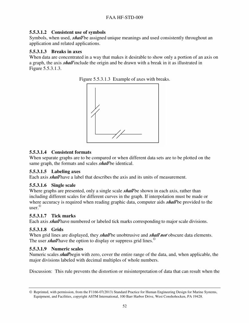
FAA HF-STD-009
© Reprinted, with permission, from the F1166-07(2013) Standard Practice for Human Engineering Design for Marine Systems,
Equipment, and Facilities, copyright ASTM International, 100 Barr Harbor Drive, West Conshohocken, PA 19428.
52
5.5.3.1.2 Consistent use of symbols
Symbols, when used, shall be assigned unique meanings and used consistently throughout an application and related applications.
5.5.3.1.3 Breaks in axes
When data are concentrated in a way that makes it desirable to show only a portion of an axis on a graph, the axis shall include the origin and be drawn with a break in it as illustrated in Figure 5.5.3.1.3.
Figure 5.5.3.1.3 Example of axes with breaks.
5.5.3.1.4 Consistent formats
When separate graphs are to be compared or when different data sets are to be plotted on the same graph, the formats and scales shall be identical.
5.5.3.1.5 Labeling axes
Each axis shall have a label that describes the axis and its units of measurement.
5.5.3.1.6 Single scale
Where graphs are presented, only a single scale shall be shown in each axis, rather than including different scales for different curves in the graph. If interpolation must be made or where accuracy is required when reading graphic data, computer aids shall be provided to the user.©
5.5.3.1.7 Tick marks
Each axis shall have numbered or labeled tick marks corresponding to major scale divisions.
5.5.3.1.8 Grids
When grid lines are displayed, they shall be unobtrusive and shall not obscure data elements. The user shall have the option to display or suppress grid lines.©
5.5.3.1.9 Numeric scales
Numeric scales shall begin with zero, cover the entire range of the data, and, when applicable, the major divisions labeled with decimal multiples of whole numbers. Discussion: This rule prevents the distortion or misinterpretation of data that can result when the

FAA HF-STD-009
© Reprinted, with permission, from the F1166-07(2013) Standard Practice for Human Engineering Design for Marine Systems,
Equipment, and Facilities, copyright ASTM International, 100 Barr Harbor Drive, West Conshohocken, PA 19428.
53
origin is omitted or if the scale does not continuously span the data range. It also helps to make valid comparisons of different graphs possible.
5.5.3.1.10 Location of legends and keys
When a graph requires a legend or key, the legend or key shall be located inside the rectangular bounds of the graph unless such a location would interfere with interpreting the displayed data.
5.5.3.2 Line format Graphic lines shall be no less than 1⁄4 pt. Graphic lines should contain a minimum of 50 resolution elements per inch, which will give the user a sense of continuity.©
5.5.3.3 Coding lines and curves When lines and curves are coded to distinguish among multiple curves on the same graph, the coding shall be used consistently throughout an application and related applications for the same types of data.
5.5.3.4 Graphic comparison Where users must evaluate the difference between two sets of data, that difference shall be plotted directly as a curve in its own right. Users shall not have to visually compare the curves that represent the original data sets.©
5.5.3.5 Bar graphs Bar graphs shall be used for comparing a single measure across a set of several entities or for a variable sampled at discrete intervals.©
5.5.3.6 Bar spacing Adjacent bars shall be spaced closely enough, normally not more than one bar width, so that a direct visual comparison can be made without eye movement.©
5.5.3.7 Histograms Histograms (bar graphs without spaces between the bars) shall be used where bar graphs are required and where a great many intervals must be plotted.©
5.6 Dynamic information update There are no applicable detailed criteria or rules for dynamic information update. See 4.6.
5.7 Coding
5.7.1 Color coding Color can be helpful in differentiating classes of information in complex, dense, and critical displays. Users often express a preference for color, even when it does not improve their performance. Although it may improve motivation and memory, performance advantages associated with the use of color tend to be highly task dependent.©
5.7.1.1 Redundant information, a source of reinforcement
When used, color coding shall only be used to reinforce the information coding provided by another technique. Color coding is most effective when a specific meaning can be attached to a color, and the color is used consistently with the same associated meaning.

FAA HF-STD-009
© Reprinted, with permission, from the F1166-07(2013) Standard Practice for Human Engineering Design for Marine Systems,
Equipment, and Facilities, copyright ASTM International, 100 Barr Harbor Drive, West Conshohocken, PA 19428.
54
5.7.1.2 Task performance aid Color shall be used only when it is associated with a purpose that aids task performance.

FAA HF-STD-009
55
Example: Using color in ATC displays is typically associated with one of the following three purposes: attention, identification, or segmentation.
5.7.1.3 Conservative use Color shall be used conservatively as an information discriminator, especially when the color deficiency in the user population is unknown.
5.7.1.4 Consistency when using color Colors shall be used consistently within a screen, within an application, and across applications.
5.7.1.5 Data categories When color is used to identify data categories, its use shall not conflict with other color-coding conventions.
5.7.1.6 Use of individual colors Colors shall be easy to discriminate from one another, with each color representing only one category of displayed data.
5.7.1.7 Color discrimination in small areas—limits Users shall not have to discriminate among colors in small areas.
5.7.1.8 Achromatic coding for small areas When small areas of the display must be coded, they shall be coded achromatically.
5.7.1.9 Retain established color meanings When the user community has previously established meanings for various colors, the designer shall retain those meanings. Thus, a color should not signify a different condition than it signified in a previous system. Discussion: Many FAA domains have set conventions regarding color use that need to be considered before applying color-coding.
5.7.1.10 Color key If the use of color does not follow well-established meanings, or if a color is used for which there is no conventional association, a color key shall be readily accessible to the user.
5.7.1.11 Color names
5.7.1.11.1 Distinctive color names
The chromaticity difference between the colors should be significant enough for each color to be distinctively named.
5.7.1.11.2 Reliable and consistent color names
The colors used to identify data categories shall be reliably and consistently named.
5.7.1.12 Discrimination and contrast
5.7.1.12.1 Color discrimination
The colors selected for color coding on a screen shall be easily distinguished from one another
in all expected operating conditions.
5.7.1.12.2 Text-background contrast
The contrast between text and background shall be sufficiently high to ensure readability of the text.
FAA HF-STD-009
56
5.7.1.13 Task performance requirements Task performance requirements shall be used as the basis for determining the number of colors presented together on the same screen.
5.7.1.14 User preferred color sets
5.7.1.14.1 Portable applications
When an application is likely to be used on different hardware configurations, it shall be able to accommodate the possible differences in color representations in the different configurations.
5.7.1.14.2 Status colors
Status colors shall be assigned during installation, and users shall not be allowed to change them.
5.7.1.14.3 Coding and status colors
When different users will share a computer monitor, individual users shall not be able to change colors for coding and status of facilities, services, or equipment such as alarms or alerts.
5.7.1.14.4 Color coding of dynamic data
Dynamic data that need to be instantly related or compared for successful task performance should be displayed in the same or similar colors.
5.7.1.14.5 Range of color contrast
When users are allowed to adjust the color and brightness contrast settings, a variety of color selections capable of producing a range of contrast levels shall be provided.
5.7.1.15 Color-coded symbols
5.7.1.15.1 Code symbol, not text
When color is used to indicate status changes, a box or other shape adjacent to the text shall
change color, instead of the text itself.
5.7.1.15.2 Refresh rate of color-coded symbols
Color-coded symbols shall have a refresh rate that provides no perceptible flicker.
5.7.2 Brightness/intensity coding
5.7.2.1 Consistent meaning Brightness coding shall have a single meaning throughout an application and related applications.
5.7.2.2 Number of levels The number of brightness intensity levels used as codes shall not exceed three. Discussion: Two levels of brightness intensity may be optimal because of possible difficulty in discriminating brightness levels. Three levels of brightness is the maximum when tasks need such discriminations.

FAA HF-STD-009
© Reprinted, with permission, from the F1166-07(2013) Standard Practice for Human Engineering Design for Marine Systems,
Equipment, and Facilities, copyright ASTM International, 100 Barr Harbor Drive, West Conshohocken, PA 19428.
57
5.7.2.3 Highlighting during operations When a user is performing an operation on a selected object in a display, that object shall be highlighted. Discussion: In many applications, at least two different methods of selection highlighting can be provided. The first highlighting method occurs when the pointer comes to rest for a predetermined time on a selected object. This is sometimes referred to as dwell emphasis, and it tells the user which object the computer perceives the user is about to select. This highlighting is normally dim white. The second highlighting method occurs when an actual selection has been made, and is normally a bright white.
5.7.2.4 Highlighting on dark backgrounds When the background is dark, white highlighting shall be used with dark letters to draw attention to particular data or portions of the screen.
5.7.2.5 Highlighting on light backgrounds When the background is light, dark highlighting shall be used with white letters to draw attention to particular data or portions of the screen.
5.7.2.6 Size and number of areas highlighted The size and number of areas highlighted shall be minimal.
5.7.3 Symbol coding
5.7.3.1 Use of symbol coding
Symbol coding may be used to enhance information assimilation from data displays. Symbols
shall be analogs of the event or system element they represent or be consistent and well known to the users. Where size difference between symbols is used, the major dimensions of the larger shall be at least 150 % of the major dimension of the smaller with a maximum of three size levels permitted.©
5.7.3.2 Special symbols
When special symbols such as asterisks or arrows are used, they shall be used consistently and with unique meanings throughout an application and related applications.
5.7.3.3 Special symbols as word markers When special symbols are used to signal critical conditions, they shall be used for only that purpose only.©
5.7.4 Size coding
5.7.4.1 Number of sizes The number of different sizes used as codes shall not exceed three. Discussion: Limiting size coding to only two to three sizes is preferable. Search time is longer for items coded by size than items coded by shape or color.

FAA HF-STD-009
© Reprinted, with permission, from the F1166-07(2013) Standard Practice for Human Engineering Design for Marine Systems,
Equipment, and Facilities, copyright ASTM International, 100 Barr Harbor Drive, West Conshohocken, PA 19428.
58
5.7.5 Flash or blink coding
5.7.5.1 Flashing rate Flash coding shall be used to call the user’s attention to mission critical events only. No more than 2 flash rates shall be used. Where one rate is used, the rate shall be 3–5 flashes per second. Where two rates are used, the second rate shall be not greater than 2 per second. The flash rate duty cycle should have a 50 % on- and 50 % off-cycle. Discussion: Although equal ON and OFF intervals are often suggested, coding can be effective even with a shorter OFF interval.©
5.7.5.2 Flash rates to avoid Flashing shall avoid rates of 10 to 25 Hz to minimize the risk of seizures for those with photosensitive epilepsy.
5.8 Interaction
5.8.1 Interaction method selection The type of interaction selected shall be appropriate to the task requirements, the characteristics of the system, and the abilities of the users. Several interaction types are listed below.
a. Question and answer interaction is appropriate when the task is routine data entry; the characteristics of the data are known and the question and answer sequence can be constrained; users are expected to have little or no training; and computer response is expected to be moderately fast.
b. Form fill-in interaction is appropriate when flexibility in data entry is needed; users can be assumed to be moderately trained; computer response may be slow; and an aid in composing complex control entries would be helpful. Note: A form-fill-in dialog shall not be used if a computer handles multiple types of forms and if the computer response time is slow.
c. Menu selection interaction is appropriate when tasks involve choices from constrained sets of alternatives; entry of arbitrary data is seldom required; users are expected to have little training; a command set is too large, too infrequent, or too inconsequential for users to remember; and computer response time is relatively fast.
d. Function key interaction is appropriate for use in conjunction with other types of interaction method when tasks require only a limited number of control entries, or when an immediate means for accomplishing frequent control entries or transactions is desirable.
e. Command language interaction is appropriate when tasks involve a wide range of control entries, users are expected to be highly trained or will use the system frequently, and control entries may be mixed with data entries in arbitrary sequence.
f. Query language interaction is appropriate when tasks emphasize unpredictable information retrieval and users are highly trained.
g. Constrained natural language interaction is appropriate when task requirements are wide-ranging or poorly defined and users are expected to have moderate training.
FAA HF-STD-009
© Reprinted, with permission, from the F1166-07(2013) Standard Practice for Human Engineering Design for Marine Systems,
Equipment, and Facilities, copyright ASTM International, 100 Barr Harbor Drive, West Conshohocken, PA 19428.
59
h. The direct manipulation interaction type is appropriate when tasks mimic physical manipulation of concrete objects such as positioning graphical objects, moving blocks of text, and resizing objects. It is also appropriate for casual system users and users expected to have little or no training.
5.8.2 Question and answer dialog
5.8.2.1 Consistency The format and Q&A procedures shall be consistent throughout an application and related applications.
5.8.2.2 Singular presentation of questions Users shall be presented only with and required to answer one question at a time.
5.8.2.3 List appropriate responses To the extent possible, users shall be provided a default or a list of the most appropriate responses from which they may select the desired response.
5.8.2.4 Sequence compatibility with source document
When questions require data entry from a source document, the question sequence shall match the data sequence within the source document.
5.8.3 Form-based interaction
5.8.3.1 Default entries Wherever possible, default entries shall appear in their respective fields when a form is displayed for form fill-in interactions.
5.8.3.2 Default listing A default listing or screen shall be provided in which authorized users may both view and change default field settings.
5.8.3.3 Variable field length indication The maximum acceptable length for variable length fields shall be indicated.©
5.8.3.4 Overwriting Data entry shall not be expected to require overwriting a set of characters in a field (such as a default).©
5.8.3.5 Dimensional units When a consistent dimensional unit is used in a given entry field, the dimensional unit shall be provided by the computer. When the dimensional unit varies for a given field, it shall be provided, or selected, by the user.©
5.8.3.6 Flexible form fill-in data entry When multiple data items are entered as a single transaction, the user shall be allowed to reenter, change, or cancel any item before taking a final Enter action.©
5.8.3.7 Informative labels Descriptive wording shall be used when labeling data fields. Use of arbitrary codes shall be avoided.©

FAA HF-STD-009
© Reprinted, with permission, from the F1166-07(2013) Standard Practice for Human Engineering Design for Marine Systems,
Equipment, and Facilities, copyright ASTM International, 100 Barr Harbor Drive, West Conshohocken, PA 19428.
60
5.8.3.8 Logical order of data items Where source documents or external information are not available, forms shall be designed so that data items are ordered in a logical sequence for data entry.©
5.8.4 Menus
5.8.4.1 Menu titles
5.8.4.1.1 Purpose of menu
Each page of options (menu) shall have a title that clarifies the purpose of that menu.©
5.8.4.1.2 Appearance of group titles
The titles of groups of options shall appear in a format that is clearly distinguishable from that of the options themselves.
5.8.4.1.3 Distinguishing menu titles
Menu titles shall be easily distinguished from the options.
5.8.4.1.4 Numbering menu titles
Menu titles shall not be numbered.
5.8.4.1.5 Capitalization in menu titles
The first letter shall be capitalized, as well as other significant words, except for prepositions and articles.
5.8.4.1.6 Acronyms in titles
When the title contains an acronym, it shall be capitalized.
5.8.4.1.7 Menu titles as options
The menu title shall not appear as an option in the menu.
5.8.4.1.8 Ellipses and right arrows
The menu title shall not contain ellipses or a right-pointing arrow.
5.8.4.2 Menu options
5.8.4.2.1 Distinguishing unavailable options
When a menu contains options that are temporarily unavailable, the unavailable options shall be displayed but clearly distinguishable from available options. Example: Unavailable options might be displayed at reduced intensity (grayed out).
5.8.4.2.2 Menus with no available options
When all the options on a menu are unavailable, then the menu title and all the options shall be disabled (grayed out).
5.8.4.2.3 Disabled menu
The user shall be able to pull down the menu to view its items even if the menu is disabled.

FAA HF-STD-009
61
5.8.4.2.4 Feedback for menu selection
When a user selects a menu option, and no computer response is immediately observable, the software shall provide some other acknowledgment of the selection. Example: The software might display a watch, hourglass, or a message stating the delay remaining or the elapsed time.
5.8.4.3 Types of options
5.8.4.3.1 Distinguishing types of options
When a menu contains options of different types, the types shall be distinguishable. Example: Options that lead to other menus might be followed by a triangle that points to where
the subsequent menu will appear (< or ∇). A menu option that requires additional information
from the user might be followed by an ellipsis (...).
5.8.4.3.2 Types of menu options
There shall be no more than two types of options in a menu: attributes and commands. Attributes are instructions that change the characteristics of a selected item. An example of an attribute is changing text from standard to bold type. Commands are instructions that cause a device to perform some action.
5.8.4.3.3 Attribute options
The titles of attribute options shall be adjectives or adjective phrases because they describe a specific feature of the attribute. Example: Choosing the option Italic changes the features of the selected text from normal to italic.
5.8.4.3.4 Command options
Command titles shall be verbs or verb phrases as they declare an action. Example: The command Save causes the computer to save the data.
5.8.4.4 Wording of options
5.8.4.4.1 Terminology
Options shall be named using terminology familiar to the user but also clearly distinguish each option from others in the menu.
5.8.4.4.2 Consistent with command language
When menu selection is used in conjunction with command language interaction, naming the menu options shall be consistent with the command language. A command language is a limited programming language used strictly for executing a series of commands (e.g., Linux, any DOS shells).

FAA HF-STD-009
62
5.8.4.5 Option organization
5.8.4.5.1 Ordering a small number of options
When a group of options or a menu contains a small number of options, the options shall be ordered by logical sequence or frequency of use.
5.8.4.5.2 Ordering a large number of options
When a group of options or a menu contains a large number of options (i.e., more than can be presented in the window or frame at one time), the GUI shall present the options ordered alphabetically, according to frequency of use, or some other rational and readily discernible scheme.
5.8.4.5.3 Logical grouping of options
When options are grouped in a menu, they shall be presented in logical groups.
5.8.4.5.4 Ordering groups
Groups of options in a menu shall be ordered logically; or, if there is no apparent logical ordering, ordered by their importance or expected frequency of use.
5.8.4.5.5 Default option
The most likely selection in a menu list shall be the default option.
5.8.4.5.6 Placing destructive command options
When menu organization is based on such principles as frequency of use, the designer shall place potentially destructive commands (Delete, Exit) at the bottom of the menu.
5.8.4.5.7 Placement of opposing action options
The designer shall not place options for opposing actions adjacent to each other. Example: Do not place the Delete option next to the Save option.
5.8.4.6 Menu bars
5.8.4.6.1 Organization of a system-level menu
The options of a system-level menu shall be grouped, labeled, and ordered in terms of their logical function, frequency of use, and criticality.
5.8.4.6.2 Availability of system-level menu options
Appropriate system-level menu options shall always be available.
5.8.4.6.3 System menu bar content
The system menu bar shall list the titles of menus that are available at the system level and provide access to the application level programs available to the user.
5.8.4.7 Pull-down menus
5.8.4.7.1 Consistent location
Pull-down menus shall always appear immediately below the option whose selection leads to their appearance.
5.8.4.7.2 Titles
The title of a pull-down menu shall be the option on the menu bar with which the pull-down menu is associated.

FAA HF-STD-009
63
5.8.4.7.3 Unique title
The title of a pull-down menu shall be unique on the menu bar and, to the extent possible, describe or identify the options in the pull-down menu.
5.8.4.7.4 Separators to divide groups of options
Separators shall be used to offset choice groups. Discussion: A group on a pull-down menu is any set of menu items between two separators or the whole list if there are no separators on the pull-down menu.
5.8.4.7.5 Pull-down menu options
The options in a pull-down menu shall be one of five types: commands, names of windows or forms that will be displayed, names of other menus, sets of exclusive options, or sets of nonexclusive options.
5.8.4.7.6 Names of windows or forms that will be displayed
When names of windows or forms that will be displayed are used as options in pull down menus, they shall be identified by a unique symbol (i.e., an ellipsis (...)).
5.8.4.7.7 Names of other menus
When names of other menus are used as options in a pull-down menu, they shall be identified by a unique symbol (i.e., an arrow (→) or triangle (>) that points to the location where the menu will appear.)
5.8.4.7.8 Sets of exclusive options
Sets of exclusive options shall be identified by a unique symbol (i.e., a filled circle (●) for a selected option and an open circle (○) for unselected options.)
5.8.4.7.9 Sets of nonexclusive options
Sets of nonexclusive options shall be identified by unique symbols (i.e., a marked square (�)
for the selected option(s), if any, and an open square (□) for the unselected option(s), if any.
5.8.4.7.10 Distinguishing unavailable options
When a pull-down menu contains options that are temporarily unavailable, the unavailable options shall be displayed but clearly distinguishable from available options. Example: Unavailable options might be displayed at reduced intensity (grayed out).
5.8.4.7.11 Options requiring more user information
When menu items on a pull-down menu require additional user information before the transaction can be completed, the designer shall use ellipses (…) after each item. Discussion: The ellipse indicates that a dialog box will be displayed when the item is selected.
5.8.4.8 Hierarchical menus
5.8.4.8.1 Consistent design and use
The design and use of hierarchical menus shall be consistent across tasks and transactions within an application.

FAA HF-STD-009
© Reprinted, with permission, from the F1166-07(2013) Standard Practice for Human Engineering Design for Marine Systems,
Equipment, and Facilities, copyright ASTM International, 100 Barr Harbor Drive, West Conshohocken, PA 19428.
64
5.8.4.8.2 Indicating current position in menu structure
An indication of the user's current position in a hierarchical menu structure shall be provided.©
5.8.4.8.3 Control entries
The top-level menu in a hierarchical menu structure shall serve as a consistent starting point for control entries. Discussion: Control entries are user input for sequence control, such as function key activation, menu selection, and command entry.
5.8.4.8.4 Return to top-level menu
A user shall be able to return to the top-level menu from anywhere in a hierarchical menu structure with one simple control action.©
5.8.4.8.5 Return to next higher level
A user shall be able to return to the next higher-level menu (back menu) from anywhere in a hierarchical menu structure with one simple control action.©
5.8.4.8.6 Direct function call for experienced users
If several levels of hierarchical menus are provided, a direct function call capability shall be provided such that the experienced user does not have to step through multiple menu levels.©
5.8.4.8.7 Position in structure
When menu traversal can be accomplished by clearly defined hierarchical paths, the user shall
be given some indication of the displayed menu’s current position in the overall or relevant structure, e.g., an optional display of “path” information or cascading menus. A menu tree showing the menu hierarchy shall be included in the user manual or online Help.©
5.8.4.8.8 Cascading menu indicator
Every cascaded menu item that leads to cascading menus shall be marked with a cascade indicator after the menu item name. Discussion: The indicator is commonly a right pointing arrow (>) that is placed on the right side of the menu option items. This tells the user that a submenu exists for that item and that, when it is selected, the submenu will appear next to the item.
5.8.4.9 Scrolling menus
5.8.4.9.1 When to use
Scrolling capability shall be provided for menus used in data entry that are too long to display in their entirety ((i.e., lists of retrievable files or acceptable entries for a field). Discussion: A scrolling menu is a menu usually containing many options that does not display all of the options at once. It includes a scrollbar that permits the sequential display of all options. Scrolling menus are also called list boxes and scrolling lists.
5.8.4.9.2 Scrollbar
The scrollbar shall be placed at the right of the displayed options.

FAA HF-STD-009
© Reprinted, with permission, from the F1166-07(2013) Standard Practice for Human Engineering Design for Marine Systems,
Equipment, and Facilities, copyright ASTM International, 100 Barr Harbor Drive, West Conshohocken, PA 19428.
65
5.8.4.9.3 Menu title
When the menu has a title, it shall appear above the displayed options and be easily distinguishable from the options.
5.8.4.9.4 Option display
The displayed options in a scrolling menu shall be arranged vertically with one option per line.
5.8.4.9.5 Display all options in a scrolling menu
All options in a scrolling menu shall be available for explicit and complete display through scrolling.
5.8.4.9.6 Indication of additional options
When many options are available, it shall be obvious to users that there are more options available than are visible. Discussion: The presence of a scrollbar may be sufficient to indicate the existence of additional options.
5.8.4.10 Pop-up menus Pop-up menus can be very useful in data entry. They can present to a user the permissible entries for a field, thus eliminating the need for the user to remember the entries, preventing invalid entries, and eliminating potential typing errors. A pop-up menu resembles a pull-down menu, but is not associated with the top-level menus listed in the menu bar.©
5.8.4.10.1 Title
A title shall be displayed for each pop-up menu.
5.8.4.10.2 Pop-up menu location
A pop-up menu shall be placed directly below the pointer used to select it and near the object or higher-level menu that is being manipulated.©
5.8.4.10.3 Indication of pop-up menu
An indication or cue shall be provided for the pop-up menu. Example: Highlight the portion of the display that can be selected to access the hidden menu, provide a textual message indicating that a hidden menu is available, or change the shape of the cursor when it is located in a selectable area.
5.8.4.10.4 Selecting an option using a pointing device
A user shall be able to select an option on a pop-up menu by moving the pointer onto the desired option and clicking the appropriate button. Explanation: This method is preferred to holding the button down while moving the cursor and releasing it to make a selection. The deliberate click method is less prone to error.

FAA HF-STD-009
© Reprinted, with permission, from the F1166-07(2013) Standard Practice for Human Engineering Design for Marine Systems,
Equipment, and Facilities, copyright ASTM International, 100 Barr Harbor Drive, West Conshohocken, PA 19428.
66
5.8.4.11 Toggled menus
5.8.4.11.1 Toggled menu options
Toggled menu options shall be used for two and only two opposite commands that are accessed frequently. Discussion: Toggled menu options are used to issue commands as a binary selection of one of two opposite commands.
5.8.4.11.2 Naming toggled menu options
Toggled menu options shall begin with verbs that clearly state the outcome of selecting that menu item.
5.8.4.12 Iconic menus When system users have different linguistic backgrounds, graphic menus may be used which display icons to represent the control options. Where the system is intended for use by foreign personnel, icon design shall be consistent with applicable cultural and ethnic variables to ensure comprehension and to avoid potential offense.©
5.8.4.13 Menu Interaction
5.8.4.13.1 Selecting menu options
The system or application shall provide a user with the ability to use any of the input devices available to select a menu option. Example: When a user has both a pointing device and a keyboard available, he or she can use either to select an option.
5.8.4.13.2 Design without pointing device
Where design constraints do not permit pointing devices, a standard window shall be provided for the user to key the selected option code.©
5.8.4.13.3 Keyed codes (mnemonics)
If menu selections must be made by keyed codes, the options shall be coded by the first several letters of their displayed labels rather than by more arbitrary numeric codes. In defining the codes, however, they should not duplicate any other user function codes.
5.8.4.13.4 Initial cursor position for keyboards
When a user selects an option using a keyboard, the cursor shall be placed on the default option in the control entry area (with that control entry area having implicit input focus) when the display appears.
5.8.4.13.5 Initial cursor position for pointing devices
When a user selects an option using a pointing device, the cursor shall be placed on the default option when the display appears.
5.8.4.13.6 Minimum pointing area size
The effective pointing area for menu options shall be at least the displayed option label plus a half-character distance around that label.

FAA HF-STD-009
67
5.8.4.13.7 Two-action activation
When menu selection is accomplished with a pointing device, activation shall consist of two actions: (1) designation, in which a user positions the cursor on the desired option, and (2) activation, in which a user makes a separate, explicit control entry (clicking the appropriate button).
5.8.4.13.8 Stacking menu selections
When selecting options from menus by entering codes, and when a series of selections can be anticipated before the menus themselves are displayed, the user shall be able to combine selections into a single, stacked entry that is equivalent to the series of selections but without having the menus displayed. Discussion: Stacking means stringing together commands so that they can be executed with a single command.
5.8.4.13.9 Mnemonic coding and keyboard accelerators in menus
5.8.4.13.9.1 Appointing a mnemonic The mnemonic for an option shall be different from any other mnemonic in the menu. Discussion: The preferred letter is the first letter. However, when that letter is used as another mnemonic in the menu or associated menus, another letter, preferably the second character letter, may be used.
5.8.4.13.9.2 Underlining mnemonic The mnemonic for an option should be underlined.
5.8.4.13.9.3 Displaying mnemonics and accelerators
Mnemonics and accelerators shall be displayed as part of the menu option. Table 5.8.4.13.9.3 shows one way of indicating mnemonics (the underscored letters) and accelerators (the key combinations at the right).
Table 5.8.4.13.9.3 Mnemonics and accelerators

FAA HF-STD-009
© Reprinted, with permission, from the F1166-07(2013) Standard Practice for Human Engineering Design for Marine Systems,
Equipment, and Facilities, copyright ASTM International, 100 Barr Harbor Drive, West Conshohocken, PA 19428.
68
5.8.4.13.10 Numbering menu options
When menu options are numbered, numbering shall start with 1, not with 0.
5.8.4.13.11 Numeric coding
When using numeric codes, six or fewer characters shall be used.
5.8.4.13.12 Displaying option codes
When menu options are coded, the codes shall be displayed with their options in a consistent, distinctive manner. Examples: When numeric coding is used, the numerals might appear immediately to the left of the options. When mnemonic coding is used, the mnemonic letter or letters might be boldfaced (Undo) or underlined (Undo).
5.8.4.13.13 Selecting an option in a menu using its accelerator
When a menu has accelerators, a user shall be able to select an option in the menu by typing its accelerator.
5.8.4.13.14 Case sensitivity of mnemonics and keyboard accelerators
Mnemonics and keyboard accelerators shall not be case sensitive, with upper and lowercase letters being equivalent.
5.8.5 Function keys
5.8.5.1 Consistency within an application When the same function is used in different operational modes within an application, it shall be assigned the same key for all modes.
5.8.5.2 Consistency across applications When the same function is used in related applications, it shall be assigned to the same key in all applications.
5.8.5.3 Functional consistency Once a key has been assigned a given function, it shall not be reassigned to a different function.©
5.8.5.4 Safeguarding Function keys that have potentially disruptive consequences shall be safeguarded. Safeguarding may take the form of physical protection, software disabling, interlocks, or multiple key combinations.
5.8.5.5 Feedback Feedback, such as a text message or audible signal, shall be provided to the user for function key activation.
5.8.5.6 Disabling of unused function keys Function keys that are unassigned or that are assigned a function that is not applicable at the moment shall be disabled.

FAA HF-STD-009
© Reprinted, with permission, from the F1166-07(2013) Standard Practice for Human Engineering Design for Marine Systems,
Equipment, and Facilities, copyright ASTM International, 100 Barr Harbor Drive, West Conshohocken, PA 19428.
69
5.8.5.7 Indicating active function keys When some function keys are active and some are not, the active keys shall be indicated. Discussion: This might be done by displaying only the active keys as soft keys on the screen or by displaying active soft keys differently from inactive ones.
5.8.5.8 Single-key operation for continuously available functions When a function is available continuously, pressing its assigned function key or selecting a corresponding soft key shall initiate the function.
5.8.5.9 Importance and frequency of use Functions shall be assigned to keys in accordance with their importance and frequency of use. Example: An emergency function might be given the most prominent position, or the most frequently used function might be given the most convenient location.
5.8.5.10 Fixed function (dedicated) keys
5.8.5.10.1 Use of fixed function (dedicated) keys
Fixed function keys shall be selected to control functions that are continuously available (i.e., lockout of fixed function keys shall be minimized). At any step in a transaction sequence, function keys not used for current inputs shall be temporarily disabled under computer control. Mechanical overlays shall not be used to temporarily disable function keys.
5.8.5.10.2 Frequently used fixed function keys
When a function is used frequently, when its use is critical, or when its timely use is critical, it shall be initiated with a single keystroke.
5.8.5.10.3 Fixed function key toggling
Except when used to toggle between two opposing states, a fixed function key shall require only a single action to accomplish its function.©
5.8.5.10.4 Non-active fixed function keys
Non-active fixed function keys shall be replaced by a blank key or grayed-out.©
5.8.5.10.5 Arrangement of fixed function keys
Fixed function keys shall be logically grouped and placed in distinctive locations on the keyboard.©
5.8.5.10.6 Acknowledgement of fixed function keys
When fixed function key activation does not result in an immediately observable natural response, the user shall be given an indication of system acknowledgment.©
5.8.5.10.7 Labeling fixed function keys
Fixed function key assignments shall be displayed at all times, shall be displayed by direct marking, and, where abbreviations are necessary for fixed function keys, standard abbreviations
shall be used.©
5.8.5.10.8 Prolonged depression of fixed function keys
Prolonged depression of function keys shall not repeat the function, except for the Delete key.©
FAA HF-STD-009
© Reprinted, with permission, from the F1166-07(2013) Standard Practice for Human Engineering Design for Marine Systems,
Equipment, and Facilities, copyright ASTM International, 100 Barr Harbor Drive, West Conshohocken, PA 19428.
70
5.8.5.11 Variable function keys
5.8.5.11.1 Use of variable function keys
Variable function keys may be used for programmable menu selection and for entering control functions. A single entry on a variable function key shall not produce a critical action. Critical actions shall require confirmation when initiated with a variable function key.©
5.8.5.11.2 Repeated key presses
Function keys shall not change function with repeated key presses unless there is a change in mode, and then only after indicating the new function.
5.8.5.11.3 No shift keying requirement for variable function keys
Shift keys shall not be required to operate variable function keys.©
5.8.5.11.4 Labeling variable function keys
When a key is used for more than one function, the user shall be informed which function is currently available. Discussion: One way to accomplish this is to display a label on a soft key on an adjacent portion of the screen.
5.8.5.11.5 Easy re-labeling of variable function keys
Provisions shall be made for easy re-labeling of variable function keys.©
5.8.5.11.6 Functional state of variable function keys
When the effect of a function key varies, the status of the key shall be displayed.©
5.8.5.11.7 Variable key reprogrammable or inactive default functions
When keys with labeled default functions are reprogrammed or turned off, a visual signal shall
signal the user that the standard function is not currently accessible via that key.©
5.8.5.11.8 Easy return to base-level functions
When the functions assigned to a set of keys change as a result of user selection, it shall be easy for the user to return them to the initial, base level functions. Discussion: One way this may be done is to include the equivalent of a "Main Menu" key in all sets other than the base set of function keys.©
5.8.6 Interactive Control
5.8.6.1 Minimal and consistent control actions Control actions shall be minimized, consistent, make minimal memory demands of the user, and be adaptable to different user needs.
5.8.6.2 Compatible dialog types Dialog types shall be compatible with anticipated task requirements and user skills.©

FAA HF-STD-009
© Reprinted, with permission, from the F1166-07(2013) Standard Practice for Human Engineering Design for Marine Systems,
Equipment, and Facilities, copyright ASTM International, 100 Barr Harbor Drive, West Conshohocken, PA 19428.
71
5.8.7 Command language
5.8.7.1 Command entry area
Each display shall provide a command entry area that is located consistently across displays
(i.e., at the bottom of the screen.©
5.8.7.2 Spelling errors Spelling and other common errors shall not produce valid system commands or initiate transactions different from those intended. The system shall recognize common misspellings of commands by informing the user of the unrecognized entry and providing a similar correct entry for revision and approval by the user. Computer-corrected commands, values, and spellings shall be displayed and highlighted for user confirmation.©
5.8.7.3 Number of characters Commands shall have at least one alphabetic or numeric character.
5.8.7.4 Non-alphanumeric characters in commands Commands consisting of only non-alphanumeric characters (i.e., $ or @) shall not be used.)
5.8.7.5 Editing commands Users shall be able to edit textual commands, after they are typed but before they are executed, using standard editing techniques.
5.8.7.6 Execution Once a textual command has been composed, an explicit Enter or execute action by the user shall
be required.
5.8.7.7 Command confirmation When executing a command that might result in deleting or modifying data or other potentially adverse consequences, the system or application shall inform the user of the nature of the consequence and request that the user confirm the command unless an Undo command is available.©
5.8.7.8 Unrecognized commands When the system or application does not recognize a user-entered command, the system or application shall inform the user and request that the user revise or replace the command.
5.8.7.9 Command prompts The user shall be able to request prompts, as necessary, to determine required parameters or available options for an appropriate next command entry.©
5.8.7.10 Macro commands The programming shall not accept a user designated macro name that is the same as an existing command name.©
5.8.8 Queries
5.8.8.1 String searches The capability shall be provided to allow the user to specify a string of text (words, phases, or numbers) to advance (or back up) the cursor automatically to the next occurrence of that string.©

FAA HF-STD-009
© Reprinted, with permission, from the F1166-07(2013) Standard Practice for Human Engineering Design for Marine Systems,
Equipment, and Facilities, copyright ASTM International, 100 Barr Harbor Drive, West Conshohocken, PA 19428.
72
5.8.8.2 Logic to link queries The query language shall be designed to include logic elements that permit users to link (e.g., “and”, “or”) sequential queries as a single entry.©
5.9 Interrupt capabilities
5.9.1 Display freeze capability
5.9.1.1 Display freeze mode A display freeze mode shall be provided to allow close scrutiny of any selected frame that is updated or advanced automatically by the system. For frozen display frames, an option shall be provided to allow resumption at the point of stoppage or at the current real-time point.©
5.9.1.2 Labeling a frozen display When a display is frozen, its frozen status shall be clearly indicated.©
5.10 File management functions
5.10.1 Clipboard
5.10.1.1 Clipboard The clipboard shall be used to transfer data among compatible applications and desk accessories.
5.10.1.2 Display clipboard contents The application shall display the contents of the clipboard in a window.
5.10.1.3 Viewable contents The contents of the clipboard shall be viewable but not editable while on the clipboard.
5.11 Transaction options
5.11.1 Selection
5.11.1.1 Highlighting
5.11.1.1.1 Highlighting critical information
Critical information in user guidance shall be highlighted using the same methods used to highlight critical information in other types of data display.
5.11.1.1.2 Highlighted text
Where text has been specified to become the subject of control entries (i.e., it has been selected for underlining, bolding, moving, copying, or deleting), the affected segment of text shall be highlighted to indicate its boundaries.©
5.11.1.1.3 Active end of selection
The active end of the selection shall be the end opposite the anchor point.
5.11.1.1.4 Extending a selection
The user shall extend the selection by moving the active end away from the anchor point.
5.11.1.1.5 Shortening selections
The user shall shorten the selection by moving the active end toward the anchor point.

FAA HF-STD-009
73
5.11.1.1.6 Insertion point
The selection shall serve as an insertion point when the active end reaches the anchor point.
5.11.1.1.7 Direction of extending selections
The user shall be able to extend a selection in either direction from the insertion point but not in both directions simultaneously.
5.11.1.1.8 De-selection and data
Deselecting shall not delete the data.
5.11.1.1.9 Items selected with outline selection
When the pointing device generating the outline is released, all objects falling completely within the outline shall be selected and preexisting selections removed. Outline selection is an extended form of drag selection that is particularly useful for graphical objects when normal drag selection conflicts with moving objects with the pointing device.
5.11.1.1.10 Outline selection of bitmaps
When outline selection is used for bitmaps, only the parts of the bitmap falling within the outline
shall be selected.
5.11.2 Stacked command execution
5.11.2.1 Entering stacked commands Stacked commands shall be entered in the same order that would be used if they were entered singularly.
5.11.2.2 Punctuation of stacked commands Required punctuation for stacked commands shall be minimal.
5.11.2.3 Delimiters for stacked commands A delimiter to separate commands shall be adopted and used consistently. Example: The slash (/) might be adopted as the delimiter, and a stacked command might be: Sort/Save/Transmit.
5.12 Control and control devices
5.12.1 Control prompt facilities The system or application shall provide the user with the required information to guide control entries. Examples: Prompts may be incorporated into a display at any point in a transaction sequence that will be helpful, or prompts may appear in response to a request for help.
5.12.1.1 Control prompt consistency When prompts are used to guide the user in making control entries, the selection prompts shall
be used consistently.
FAA HF-STD-009
© Reprinted, with permission, from the F1166-07(2013) Standard Practice for Human Engineering Design for Marine Systems,
Equipment, and Facilities, copyright ASTM International, 100 Barr Harbor Drive, West Conshohocken, PA 19428.
74
5.12.1.2 List of control options A list of basic control options that are always available to a user shall be easily displayable. Discussion: This list can serve as a "home base" or starting point for control entries. An example is the system-level menu.
5.12.1.3 Option code display When users select options by entering codes, the code associated with each option shall be displayed in a consistent manner and shall be distinct from other codes.
5.12.1.4 Default control When control is accomplished by keyed command or option code entries and a default entry is defined, the default shall be displayed to the user.
5.12.1.5 Default control positioning (for pointing devices) When a user must select among displayed options using a pointing device, the cursor shall be placed on the default option when the display appears. A cursor is a marker on the display screen that indicates the position where the computer expects the next input or will display the next output. The cursor may be positioned by the computer or by the user.
5.12.1.6 Default control positioning (for keyboards) When a user must select among displayed options using a keyboard, the cursor shall be placed on the default option in the control entry area (with that control entry area having implicit input focus) when the display appears.
5.12.1.7 Consistent continue options At any step in a defined sequence of transactions, if there is only a single next step, the system or application shall provide a consistent Continue option.
5.12.1.8 Control option for signaling data entry When sequential data entry is involved, an explicit Enter or Tab control option signaling data entry shall be used rather than a Continue or Next option.
5.12.2 Hierarchical levels of control
5.12.2.1 Hierarchical levels When hierarchical levels are used to control a process or sequence, the number of levels shall be kept few in number.©
5.12.2.2 Hierarchical levels format When hierarchical levels are used, display and input formats shall be similar within levels.©
5.12.2.3 Hierarchical levels current position When hierarchical levels are used, the system shall indicate the current position within a sequence.©
5.12.2.4 Control locations and options Screen control locations and options shall be clearly and appropriately indicated.

FAA HF-STD-009
© Reprinted, with permission, from the F1166-07(2013) Standard Practice for Human Engineering Design for Marine Systems,
Equipment, and Facilities, copyright ASTM International, 100 Barr Harbor Drive, West Conshohocken, PA 19428.
75
5.12.2.5 Interactive control functions If interactive control functions are included with the display, they shall be within the anthropometric reach of the operator using them.
5.12.2.6 Control compatibility with user skill Controls shall be compatible with the lowest anticipated skill level for the potential user.©
5.12.2.7 Options for experienced users Experienced users shall have options which shortcut intervening steps necessary for inexperienced users.
5.12.2.8 Accidental control actuation Provision shall be made to prevent accidental actuation of potentially destructive control actions, including the possibility of accidental erasure or memory dump.©
5.12.2.9 Decimal control inputs When numeric data are displayed or required for control input, such data shall be in the decimal, rather than binary, octal, hexadecimal, or other number system.© Note: When numeric data is not displayed in the decimal format due to operational requirements, the alternate number system used shall be clear to the user.©
5.12.2.10 Default values When the system prompts a user for a parameter that has a default value assigned, the default value shall be displayed.
5.12.2.11 Control information When a control for manipulating the display becomes available, information that the user needs for its use shall be displayed.
5.12.2.12 Distinctive display of control information Displays shall be designed so that features relevant to the interactive method, such as prompts and messages, are distinctive in position and format.
5.12.2.13 Control input data display The presence and location of control input data entered by the user shall be clearly and appropriately indicated. Data displayed shall not mislead the user with regard to nomenclature, units of measure, sequence of task steps, or time phasing.©
5.12.2.14 Concurrent display Control actions to be selected from a discrete set of alternatives shall have those alternatives displayed before the time of selection. The current value of any parameter or variable with which the user is interacting shall be displayed. User control inputs shall result in a positive feedback response displayed to indicate performance of requested actions.©

FAA HF-STD-009
© Reprinted, with permission, from the F1166-07(2013) Standard Practice for Human Engineering Design for Marine Systems,
Equipment, and Facilities, copyright ASTM International, 100 Barr Harbor Drive, West Conshohocken, PA 19428.
76
5.12.3 Icons Visual symbols are simple pictorial representations that stand for something else. Visual symbols displayed on computer screens for the purpose of interacting with the system are often referred to as icons. Icons may be used to represent operations, processes, and data structures graphically, and they may be used as a means of exercising control over system functions, components, and data structures.
5.12.3.1 Description An icon shall consist of a graphic image and an identifying label.©
5.12.3.2 Icon label presentation Each icon shall have a text label corresponding to the object or action, which appears adjacent to the icon shortly after the pointer focus is placed on the icon.
5.12.3.3 Obscuring label The label shall not obscure the icon.
5.12.3.4 Consistency
When images are used to identify controls, status indicators, or other programmatic elements, the meaning assigned to those images shall be consistent throughout an application and across related applications.©
5.12.3.5 Selectable area of an icon
The selectable area of an icon shall be large enough to reduce the risk of error and increase the user’s ease in selecting the icon.©
5.12.3.6 Minimum selectable area The selectable area or hot spot outside of the area of the icon shall be at least 4 millimeters. The selectable area in which a user can place the pointer and successfully select an icon is often called the hot spot.©
5.12.3.7 Icon spacing Icons shall be positioned at least 10 millimeters apart from each other, as measured from perimeter to perimeter.©
5.12.3.8 Icon documentation A glossary shall be provided in on-line help containing a list of standard icons and their associated objects and actions.
5.12.3.9 Action icons bound to window When a window includes action icons, a user shall not be able to move the icons outside the window.
5.12.4 Palettes (graphic menus) Lists and palettes are both effective ways of allowing users to access options. Palettes can be used in selecting icons, patterns, colors, characters, or drawings. They allow the user to select an action or attribute from a group of icons fixed in a window. Palettes can be fixed or floating.©

FAA HF-STD-009
© Reprinted, with permission, from the F1166-07(2013) Standard Practice for Human Engineering Design for Marine Systems,
Equipment, and Facilities, copyright ASTM International, 100 Barr Harbor Drive, West Conshohocken, PA 19428.
77
5.12.5 Pushbutton This section presents rules on pushbutton (also referred to as command buttons) for general use.
5.12.5.1 Push button labels A push button shall have either a text or graphic label.©
5.12.5.2 Consistent push button labels Push button labels shall be consistent throughout an application and related applications.
5.12.5.3 Push button appearance The states of a pushbutton shall be distinguishable for the user by appearance.©
5.12.5.4 Activating a push button
A user shall be able to activate a push button by moving the pointer onto the button and pressing the appropriate pointer button.
5.12.5.5 Activated pushbutton The push button shall be highlighted while the pointer button is depressed.
5.12.5.6 Activating controls using pushbutton The control shall be activated when the pointer button is released, and the push button is reverted to its normal appearance.
5.12.5.7 Activating buttons using the keyboard
A user shall be able to activate a push button using the keyboard.
5.12.5.8 Default pushbutton Default pushbutton shall be clearly distinguishable from other pushbutton. Example: They may have an extra border as illustrated in Figure 5.12.5.8, be highlighted, or appear three-dimensional.©
Figure 5.12.5.8 Example of a default pushbutton.
5.12.6 Radio buttons Radio buttons (also known as exclusive buttons or option buttons) are single, two-state choices, which are mutually exclusive from each other.©
5.12.6.1 When to use Radio buttons shall be used if it is required that one and only one of a set of mutually exclusive options be selected.©
FAA HF-STD-009
© Reprinted, with permission, from the F1166-07(2013) Standard Practice for Human Engineering Design for Marine Systems,
Equipment, and Facilities, copyright ASTM International, 100 Barr Harbor Drive, West Conshohocken, PA 19428.
78
5.12.6.2 Radio button appearance A box should be drawn around a group of radio buttons to visually separate the group from other interface features. When a specific option is not available, it should be displayed as subdued or grayed-out in relation to the brightness of the available options.©
5.12.6.3 Number of radio buttons An individual radio button shall always be part of a mutually exclusive group of two or more radio buttons.©
5.12.6.4 Selecting a radio button inactivates other radio buttons A radio button that is active shall cause all of the other radio buttons in its group to be inactive.©
5.12.6.5 Selecting a radio button using a pointing device A user shall be able to select a radio button using a pointing device by moving the pointer onto the radio button and clicking the appropriate device button.©
5.12.6.6 Selecting a radio button using the keyboard A user shall be able to select a radio button using the keyboard by moving a location cursor to the desired button (i.e., using the arrow keys) and pressing the Enter key.©
5.12.6.7 Exclusive selection Selecting one radio button item shall deselect any other radio button in its group previously selected.
5.12.6.8 Selected button highlighted Selecting a button that is already highlighted shall not change its state.
5.12.6.9 Radio button labels Labels shall be provided for each set of radio buttons.©
5.12.6.10 Labeling individual radio buttons Radio buttons and labels shall be left justified in the column format.
5.12.6.11 Labeling single panels of radio buttons
When a screen or window contains only one panel of radio buttons, the screen or window title
shall serve as the panel label.
5.12.6.12 Selection area The selection target area for radio buttons shall include the radio button and its label.
5.12.6.13 Moving a cursor to an option
Moving the cursor to an option shall highlight the label by reverse video, reverse color, or a dashed box around the label.
5.12.6.14 Sets of radio buttons Radio button sets should contain from two to seven items, but the user shall always have at least two radio buttons in each set. Discussion: When 9 or more options must be presented, consider using a scrollable list or a drop-down list instead of radio buttons.

FAA HF-STD-009
© Reprinted, with permission, from the F1166-07(2013) Standard Practice for Human Engineering Design for Marine Systems,
Equipment, and Facilities, copyright ASTM International, 100 Barr Harbor Drive, West Conshohocken, PA 19428.
79
5.12.7 Check boxes Check boxes (also known as nonexclusive buttons) are single, two-state choices (i.e., a check box can be on (checked) or off (not checked). A check box group is a collection of two-state choices, all of which apply to the same selected object. Check boxes can be grouped.
5.12.7.1 When to use Check boxes shall be provided if a user may select multiple (or none) of the available options. Example: In specifying the appearance of text, a user might want to select both Bold and Italic.©
5.12.7.2 Effect of activating a check box A check box that is activated shall not change the status of any other choice in the group.
5.12.7.3 Selecting check boxes Users shall be able to toggle selected and unselected states on a check box using either a pointing device or the keyboard.©
5.12.7.4 Check box states
Check boxes shall have two states, selected and unselected.©
5.12.7.5 Labeling check boxes
Labels shall be provided for each set or group of check boxes and for each individual check box in the set or group.©
5.12.7.6 Arrangement of check boxes Check boxes shall be arranged in logical order so that the most frequently used boxes are at the top or at the left, depending on how the check boxes are oriented.©
5.12.7.7 Check box height and width When grouping check boxes, the boxes shall be equal in height and width.
5.12.7.7.1 Scrollbar on combo list box
The scrollbar shall only be used on a combo list box if the list is expected to display more entries than can be shown at one time.
5.12.8 Special graphical controls A graphic control allows for a simple interpretation of what the control represents and how it works. Specially designed graphics maintain this idea with each graphic being unique in appearance and function. A specialized graphic clearly represents an actual physical object and is only used when it is less complicated than other options offered by the application. Examples of graphical controls include sliders, volume knobs, color wheels, and color sliders.

FAA HF-STD-009
© Reprinted, with permission, from the F1166-07(2013) Standard Practice for Human Engineering Design for Marine Systems,
Equipment, and Facilities, copyright ASTM International, 100 Barr Harbor Drive, West Conshohocken, PA 19428.
80
5.12.8.1 Sliders Sliders are appropriate and should be used when users must set a value within a fixed range and the precise value is less important than relative position.©
5.12.8.1.1 Components of a slider
Slider designs shall contain the following components: a. A slider shall have a movable marker that indicates the current setting and a line or
rectangular area along which it moves. b. A slider shall have a label or title that indicates the purpose of the slider. When
appropriate, the slider should provide a numerical readout of the current setting. Discussion: Tick marks and numeric values may be added to the line or rectangular area of the slider.©
5.12.8.1.2 Slider operation
Users shall be able to change the setting of a slider by moving the pointer onto the marker and dragging it.©
5.12.9 Cursors
5.12.9.1 Pointing via movable cursors A movable cursor within the display shall have a distinctive visual attribute that does not obscure other displayed entities. When fine positioning accuracy is required, as in some forms of graphic and image processing applications, the displayed cursor shall include an appropriate point designation feature (such as crosshairs). The cursor shall not move beyond the display boundaries and disappear from sight. If the cursor is moved by depressing a key, releasing the key shall cause the cursor to stop moving.©
5.12.9.2 Multiple cursors Multiple cursors shall be avoided unless needed for user tasks.
5.12.9.3 Distinguishing cursors
When more than one cursor is provided, each shall be easily distinguishable from the other(s),
with the status of each (active or inactive) being easily distinguishable.
5.12.9.4 Home position The home position for the cursor shall be consistent across similar types of displays.©
5.12.9.5 Movement relationships The response of a cursor to control movements shall be consistent, predictable, and compatible with the user's expectations. For cursor control by key action, the cursor shall move in the corresponding direction of the arrow key that was pressed (i.e., left arrow to left, right arrow to right, up arrow up, down arrow down). For cursor control by joystick, movement of the control shall result in the cursor moving in the corresponding direction (i.e., left movement moves cursor to the left, right movement to the right, push movement up, and pull movement down).©
5.12.9.6 Cursor movement within a page When entering and editing text, users shall be able to move the cursor freely within a displayed page to specify items for change and to make changes directly in the text.

FAA HF-STD-009
© Reprinted, with permission, from the F1166-07(2013) Standard Practice for Human Engineering Design for Marine Systems,
Equipment, and Facilities, copyright ASTM International, 100 Barr Harbor Drive, West Conshohocken, PA 19428.
81
5.12.9.7 Cursor movement within a file The means shall be provided to readily move the cursor to the head or the foot (end) of the file.©
5.12.9.8 Consistent positioning Where cursor positioning is incremental by discrete steps, the step size of cursor movement shall
be consistent horizontally (that is, in both right and left directions) and vertically (in both up and down directions).©
5.12.9.9 Cursor control via keyboard When position designation is required in a task emphasizing keyed data entry, cursor control shall be by some device integral to the keyboard. If cursor movement is accomplished by depressing keys, the keys shall be located on the main keyboard.©
5.12.9.10 Explicit actuation A separate, explicit action, distinct from cursor position, shall be required for the actual entry (for example, enabling, actuation) of a designated position. For most graphics data entry, pointing shall be a dual action, with the first action positioning the cursor at a desired position and the second action confirming that position to the computer. An exception may be a design allowing “freehand” drawing of continuous lines where the computer must store and display a series of cursor positions as they are entered by the user.©
5.12.9.11 Explicit delete action Data deletion or cancellation shall require an explicit action, such as depressing a Delete key. Permanent deletion (in absence of an “Undo” function) of more than one character shall not be allowed without an affirmative response to an “Are you sure?” type of query.©
5.12.9.12 Text cursor
5.12.9.12.1 Text cursor
The text cursor shall be an I-beam in insert mode and a box over a character in replace mode.
5.12.9.12.2 Text cursor height
The height of an I-beam text cursor shall be the same as that of the adjacent text character.
5.12.9.12.3 Text cursor flash rate
The text cursor shall flash at a rate between 2 and 5 Hz. Discussion: A blink rate of 2 to 3 Hz with a 50% duty cycle is preferred. With a 50% duty cycle, the cursor would be ON half the time and OFF half the time. In some systems, users are allowed to set the blink rate for a location cursor through window management functions.
5.12.9.12.4 Avoiding flashing-induced seizures
Flash or display refresh rate shall not be within the 15-20 Hz range. Discussion: People who are sensitive to seizures may have seizures induced by flashing screen cursors or by flickering displays, particularly near the 15-20 Hz range. Therefore, flicker or refresh rates should be as far above or below this range as possible or practical.
5.12.9.12.5 Lost input focus
When the text object containing the text cursor loses input focus, the cursor shall stop flashing.
FAA HF-STD-009
© Reprinted, with permission, from the F1166-07(2013) Standard Practice for Human Engineering Design for Marine Systems,
Equipment, and Facilities, copyright ASTM International, 100 Barr Harbor Drive, West Conshohocken, PA 19428.
82
5.12.9.12.6 Regained text object input focus
When the text object regains input focus, the cursor shall return to normal brightness and resume flashing. Discussion: Input focus means that the indicated location, window, or object in the text field is currently active. Unless the user changes this active state, that will be the object or location that will be acted upon by the next text editing or entry transaction.
5.12.9.12.7 Text cursor location
When a window first receives input focus, the text cursor shall be placed in the text area where typing is most likely to occur.©
5.12.9.12.8 Regaining window input focus
When the cursor disappears from view when its window loses focus, the cursor shall reappear at the same location when the window regains focus.
5.12.9.12.9 Input device for moving the text cursor
Users shall be able to move the text cursor within and among text entry areas using both the pointing device and the keyboard.
5.12.9.12.10 Text cursor display
The pointer shall change to an I-beam (text cursor) only when the pointer moves into a text entry area.
5.12.9.12.11 Moving text cursor out of text entry area
Users shall not be able to move the text cursor into non-text entry areas.
5.12.9.13 Graphics cursor When fine positioning accuracy is required, as in some forms of graphic and image-processing applications, the displayed cursor shall include an appropriate point designation feature (such as crosshairs).©
5.12.9.14 Input focus indication A well-defined on-screen indication of the current focus shall be provided that moves among interactive interface elements as the input focus changes.©
5.12.9.15 Position or pointing cursors Position or pointing cursors are used to point to controls on a display. They may at times obscure other screen objects. The pointer cursor is often the left pointing arrow. The pointer is used to make selections and to click in menus and control buttons; to resize windows; to click, hold, and drag objects; and to click on a location to move the location cursor in text and field editing.
5.12.9.15.1 Size
Position or pointing cursors shall maintain their size across all screen locations during movement.
5.12.9.15.2 Non-blinking pointing cursors
Position or pointing cursors shall not blink.
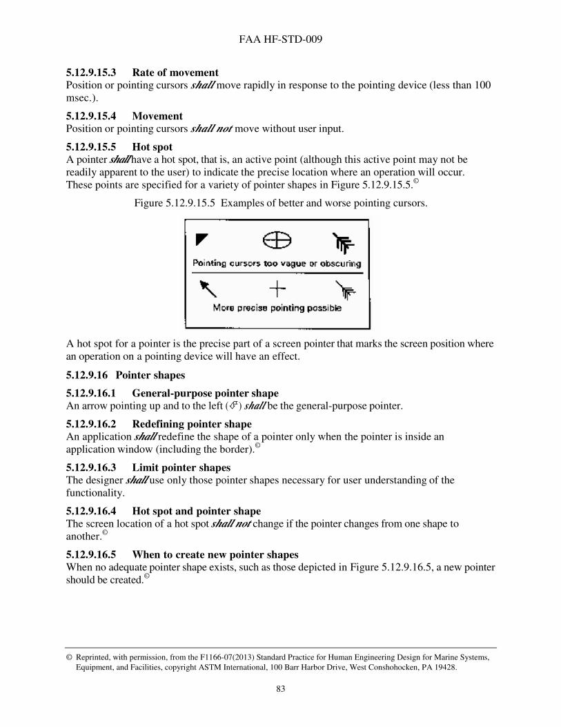
FAA HF-STD-009
© Reprinted, with permission, from the F1166-07(2013) Standard Practice for Human Engineering Design for Marine Systems,
Equipment, and Facilities, copyright ASTM International, 100 Barr Harbor Drive, West Conshohocken, PA 19428.
83
5.12.9.15.3 Rate of movement
Position or pointing cursors shall move rapidly in response to the pointing device (less than 100 msec.).
5.12.9.15.4 Movement
Position or pointing cursors shall not move without user input.
5.12.9.15.5 Hot spot
A pointer shall have a hot spot, that is, an active point (although this active point may not be readily apparent to the user) to indicate the precise location where an operation will occur. These points are specified for a variety of pointer shapes in Figure 5.12.9.15.5.©
Figure 5.12.9.15.5 Examples of better and worse pointing cursors.
A hot spot for a pointer is the precise part of a screen pointer that marks the screen position where an operation on a pointing device will have an effect.
5.12.9.16 Pointer shapes
5.12.9.16.1 General-purpose pointer shape
An arrow pointing up and to the left (�) shall be the general-purpose pointer.
5.12.9.16.2 Redefining pointer shape
An application shall redefine the shape of a pointer only when the pointer is inside an application window (including the border).©
5.12.9.16.3 Limit pointer shapes
The designer shall use only those pointer shapes necessary for user understanding of the functionality.
5.12.9.16.4 Hot spot and pointer shape
The screen location of a hot spot shall not change if the pointer changes from one shape to another.©
5.12.9.16.5 When to create new pointer shapes
When no adequate pointer shape exists, such as those depicted in Figure 5.12.9.16.5, a new pointer should be created.©

FAA HF-STD-009
© Reprinted, with permission, from the F1166-07(2013) Standard Practice for Human Engineering Design for Marine Systems,
Equipment, and Facilities, copyright ASTM International, 100 Barr Harbor Drive, West Conshohocken, PA 19428.
84

FAA HF-STD-009
85
Figure 5.12.9.16.5 Pointer shapes associated with functions.

FAA HF-STD-009
© Reprinted, with permission, from the F1166-07(2013) Standard Practice for Human Engineering Design for Marine Systems,
Equipment, and Facilities, copyright ASTM International, 100 Barr Harbor Drive, West Conshohocken, PA 19428.
86
5.12.9.17 Location cursors Location cursors serve to show the location of an operation on a display. The location pointer is usually an I-beam cursor in text processing or data entry.
5.12.9.17.1 Distinctive against background
Location cursors shall be distinctive against their backgrounds.
5.12.9.17.2 Obscuring characters
Location cursors shall not obscure characters.
5.13 Windowing This section contains rules on windows with the exception of help windows, which may be found elsewhere in this document (see 5.15.4).
5.13.1 Window components This section contains general rules on particular window components. Refer to the specific subsection on window types to find type-specific information on each of these components.
5.13.1.1 Title bar and title All windows shall contain a title bar, located at the top of the window, which provides a title and access to all of the controls available to the open window. The titles of subordinate (secondary) windows shall correlate with the menu selection items from the main window menu.©
5.13.1.1.1 Titles for primary windows
The title shall be the application name followed by the opened file name, separated by a single dash (-).
5.13.1.1.2 Titles for secondary windows
Titles shall begin with the object under focus and be followed by the action underway. Example: Printer - Set Up is the title with the printer being the object under focus and the action underway being a set-up action.
5.13.1.1.3 Capitalization in window titles
Significant words in the title shall be capitalized.
5.13.1.2 Working or client area
5.13.1.2.1 Working or client area of windows
Every window shall have a working or client area. A working area (or client area) is the main area of the window that users employ to do their operational or application tasks. It is the area where users enter inputs and receive their outputs.
5.13.1.3 Scrollbars
5.13.1.3.1 Using scrollbars
Scrollbars shall be used to view textual or graphic information when it exceeds the available display area in the window and shall not be used, or disabled if all information can be viewed
FAA HF-STD-009
© Reprinted, with permission, from the F1166-07(2013) Standard Practice for Human Engineering Design for Marine Systems,
Equipment, and Facilities, copyright ASTM International, 100 Barr Harbor Drive, West Conshohocken, PA 19428.
87
simultaneously. Vertical (top-to-bottom) scrolling is usually preferred over horizontal (left-to-right) scrolling.©
5.13.1.3.2 Scrollbar location
If used, a horizontal scrollbar shall appear at the bottom of the window and a vertical scrollbar shall appear on the right side of the window.©
5.13.1.3.3 Scrollbars on active windows
Scrollbars shall be displayed in full contrast for the active window only (the window that displays the user’s current input).
5.13.1.3.4 Changing scrollbar components
Scrollbar components shall change to reflect the present status when the window size or information position changes.
5.13.1.3.5 Subdued directional arrows
The appropriate directional arrow shall be subdued or grayed out if no information is currently available through scrolling in a particular direction.
5.13.1.3.6 Scrollbar entire-entity indicator
A scrollbar shall contain a vertical or horizontal line or area along which the scroll box can move, the length of which represents the entire entity.
5.13.1.3.7 Scroll box
A scrollbar shall contain a movable symbol such as a box or rectangle that contrasts with the scroll area. Discussion: The scroll box is also known as the slider box or scroll handle.
5.13.1.3.8 Scroll box size
The size of the scroll box shall indicate proportionately the amount of the document displayed in the window relative to the percentage of available information in the file being viewed. Discussion: If the document is short, the displayed amount (as a percentage) of the document is large and thus so is the scroll box. If the document is long, then the displayed amount and scroll box are small. For long documents, a minimal or default size scroll box is used.
5.13.1.3.9 Scroll box operations
Users shall be able to drag the scroll box continuously along its line or area using a pointing device.
5.13.1.3.10 Moving through pages using a scrollbar
A scrollbar shall contain two symbols that allow a user to move forward or backward through the entire document one page at a time.©
5.13.1.3.11 Scrollbar on combo list box
The scrollbar shall only be used on a combo list box if the list is expected to display more entries than can be shown at one time.

FAA HF-STD-009
© Reprinted, with permission, from the F1166-07(2013) Standard Practice for Human Engineering Design for Marine Systems,
Equipment, and Facilities, copyright ASTM International, 100 Barr Harbor Drive, West Conshohocken, PA 19428.
88
5.13.1.4 Menu bar Menu bars shall be used only in primary windows. There shall be no more than one menu bar in a given window. The menu bar shall be located at the very top of the application area and extend the full width of the window.©
5.13.1.5 Message bar The information area in primary windows is called the message bar or message area.
5.13.1.5.1 Message types
The message bar shall be a read-only, non-scrolling display for messages.
5.13.1.6 Status bar The status bar shall be located at the bottom of a window, just inside the window frame.
5.13.1.7 Control bar Control bars can be rulers, such as in word processing programs, or toolboxes and color/pattern palettes, such as in graphics programs.
5.13.1.7.1 Consistent placement of control bars
Control bars shall be displayed in a horizontal row or vertical column. When the same control bars are used in different windows, they should be placed consistently in the same location.
5.13.1.7.2 Control bar location
A window shall never conceal the movable control bar with which it is associated.
5.13.1.8 Pushbutton This section presents rules for pushbutton specific to their use in windows.
5.13.1.8.1 Default window pushbutton
Default pushbutton shall be clearly distinguishable from the other pushbutton using visual features such as highlighting or appearing three dimensional.©
5.13.1.8.2 Default button safeguard
A push button assigned an action that is potentially destructive shall not be designated as the default button.
5.13.1.8.3 Window push button size and shape
All pushbutton in a window should have the same size and shape.©
5.13.1.8.4 Consistent window push button labels
A push button shall have a consistent text or graphic label that should describe the results of pressing the button and reflect the action that will be taken by the application rather than the user.©
5.13.2 Window types
5.13.2.1 Primary and secondary windows A primary window is a top or high-level window in an application. A secondary window is a window that is displayed from within a primary window or another secondary window. Secondary windows are sometimes called child windows.

FAA HF-STD-009
© Reprinted, with permission, from the F1166-07(2013) Standard Practice for Human Engineering Design for Marine Systems,
Equipment, and Facilities, copyright ASTM International, 100 Barr Harbor Drive, West Conshohocken, PA 19428.
89
5.13.2.1.1 Use of primary and secondary windows
An application shall use one or more primary windows for the performance of primary operational task(s) and secondary windows to present supplementary or supporting data related to a primary task(s). Secondary windows may include message windows or windows for short-term interactions related to subtask or functional control or message windows for presenting messages to users.©
5.13.2.1.2 Primary window components
A primary window shall contain a title bar, a border, window controls, and a working area or client area. Discussion: The primary window also may also contain a menu bar, other controls, objects, and icons.
5.13.2.1.3 Initial primary window
Every application with a user interface shall initially display a primary window. A primary window shall be displayed as soon as the application starts.©
5.13.2.1.4 Secondary window components
A secondary window shall contain a title bar, a working area, and any of the other window components appropriate to the application.
5.13.2.1.5 Limit use of secondary windows
The usage of secondary windows should be limited. The default size of a secondary window
shall be as small as possible to convey the needed information.©
5.13.2.2 Application windows
5.13.2.2.1 Location of title bar
The title bar shall extend across the top of the window.
5.13.2.2.2 Location of title in window title bar
The window title shall appear centered in the window title bar.
5.13.2.2.3 Capitalization of title
The window title shall be in mixed-case letters.
5.13.2.2.4 Title content
The title shall be as informative as possible, describing the purpose of the window and may also include the name of the application.
5.13.2.2.5 Title of window based on option selection
When a window is displayed as a result of selecting an option in a menu, the title wording for the window shall be the same as the option wording.
5.13.2.2.6 Location of window controls
Window controls shall be located on the title bar with Minimize, Restore/ Maximize, and Close options at the right end and a control producing a menu of window management options on the left end.
5.13.2.2.7 Location of menu bar
When used, the menu bar shall extend across the window just below the title bar.

FAA HF-STD-009
© Reprinted, with permission, from the F1166-07(2013) Standard Practice for Human Engineering Design for Marine Systems,
Equipment, and Facilities, copyright ASTM International, 100 Barr Harbor Drive, West Conshohocken, PA 19428.
90
5.13.2.2.8 Location of working area
The working area shall occupy all the space inside the border that is not occupied by another component.
5.13.2.2.9 Location of command entry area
When used, the command entry area shall extend across the bottom of the window just above the message area.
5.13.2.2.10 Location of message area
When used, the message area shall extend across the bottom of the window.
5.13.2.3 The system window
5.13.2.3.1 Appearance
The system window shall appear when system startup is complete.
5.13.2.3.2 System-window size
The system window shall occupy the entire screen.
5.13.2.3.3 System-window components
All system windows shall have a border or frame, a title bar, window controls, and a working area.
5.13.2.3.4 Location of system title bar
The system window shall contain a system title bar that extends across the top of the screen.
5.13.2.3.5 Location of system title bar title
The system-title bar shall be centered and contain a title that identifies the system. Discussion: The system-title bar may also include optional components such as status indicators and a date and time display.
5.13.2.3.6 Location of menu bar
The system window shall contain a system-menu bar that extends across the screen located just below the system-title bar.
5.13.2.3.7 Display area
The system window shall contain an area available for the display of application windows that occupies the remainder of the screen. Discussion: The application area of the system window may contain icons that represent application windows or action icons common to all applications.
5.13.2.3.8 Saving entered data
When a user has finished making entries in a data-entry window, he or she shall be able to save the entries by taking an explicit action such as selecting a Save menu option or activating an Apply or OK push button.©

FAA HF-STD-009
© Reprinted, with permission, from the F1166-07(2013) Standard Practice for Human Engineering Design for Marine Systems,
Equipment, and Facilities, copyright ASTM International, 100 Barr Harbor Drive, West Conshohocken, PA 19428.
91
5.13.2.4 Text windows
5.13.2.4.1 Text window too small for entire document
When an entire text document does not fit in the current window, the window shall have a vertical scrollbar or a similar mechanism (positioned on the right side of the window) so that users can view the entire document.
5.13.2.5 Message windows The following requirements are relevant to message windows.
5.13.2.5.1 Message window contents and mobility
Message windows shall contain a title, a message, and one or more pushbutton. They should also contain information and options for user interaction. If it is necessary to view information in other windows while viewing a message box, the message window shall be movable.©
5.13.2.5.2 Message window location
Alarm (warning) and alert (caution) windows and other message windows shall be front most on the display.©
5.13.2.5.3 Message window size
Users shall not be able to minimize or resize message windows.©
5.13.2.5.4 Message window for action confirmation
Destructive actions shall be preceded by a user confirmation (at least one extra step) in a message window.©
5.13.2.5.5 Message window control button locations
The control buttons used to enter a command from a message window shall be located consistently at the bottom of the message window. The default button shall be consistently located on the left side of the message window. The button with the opposing action shall be located on the right side. Any additional control buttons shall be located between the default and opposing action buttons.©
5.13.2.5.6 Default message window control buttons
In message windows, the default control button shall be a non-destructive button, such that it would be activated only if an operator presses Enter. The default button shall be highlighted (i.e., by adding an extra border around it).©
5.13.2.6 Information message windows The following requirements are relevant to information message windows.
5.13.2.6.1 Modal information message windows
Information message windows shall be modal and require acknowledgement.
5.13.2.6.2 Information message window behavior
Information message windows shall not appear to the user to interrupt processing by the application. Discussion: If the application interrupts processing, it must be transparent to the user.
5.13.2.7 Working message window The following requirements are relevant to working message windows.

FAA HF-STD-009
© Reprinted, with permission, from the F1166-07(2013) Standard Practice for Human Engineering Design for Marine Systems,
Equipment, and Facilities, copyright ASTM International, 100 Barr Harbor Drive, West Conshohocken, PA 19428.
92
5.13.2.7.1 Working message window use
When the processing time resulting from a user action will exceed 2 seconds, the system shall
display a working message window.
5.13.2.7.2 Working message windows
The display of a working message window shall not interrupt processing.
5.13.2.7.3 Working message window display
The working message window shall remain on display until processing is completed or until the user minimizes the window or cancels the process.
5.13.2.7.4 Working message window removal
The window shall be removed automatically when processing is completed.
5.13.2.7.5 Working message window contents
Working message windows shall contain a working symbol, a message, and one of the following sets of pushbutton below the message, in the order listed: {OK and Help}, {OK, Cancel, and Help}, {OK, Stop, and Help}, or {OK, Pause, Resume, Stop, and Help}.
5.13.2.8 Dialog boxes Dialog boxes may be movable or fixed, of a single size or two alternate sizes, modal (requiring a response before continuing), semi-modal, or modeless, and may present limited response options or more complex options.
5.13.2.8.1 Error dialog box modality
Error windows shall be modal, requiring user acknowledgement in order to continue. Discussion: An accompanying auditory alert indicating the nature of the error may be considered if warranted by the criticality of the error and the logic of the system.
5.13.2.8.2 Critical messages in dialog boxes
Messages that are critical or that require user acknowledgment (e.g., error messages) shall
appear in their own dialog boxes.©
5.13.3 Window states The following requirements relate to specific window states.
5.13.3.1 Initial/default sizing The default size for a window should be large enough to present all relevant information for the task, not obscure important information, not cause crowding or visual confusion, and minimize the need for scrolling. The size of the initial presentation of a window shall be consistent with its contents (i.e., the amount of information to be displayed, number of menus, data fields, etc.).©
5.13.3.2 Open windows The following requirements detail general features required of the open window state.
5.13.3.2.1 Open and activate window
Users shall be able to open a window with a single action. The action that opens a window shall
automatically make that window active.©
FAA HF-STD-009
© Reprinted, with permission, from the F1166-07(2013) Standard Practice for Human Engineering Design for Marine Systems,
Equipment, and Facilities, copyright ASTM International, 100 Barr Harbor Drive, West Conshohocken, PA 19428.
93
5.13.3.2.2 Input from system
An open window shall be capable of receiving input from the system.
5.13.3.2.3 Input from user
A window that is open and active shall be capable of receiving input from a user.©
5.13.3.2.4 Visibility
An open window shall be completely visible on the screen at the time it is opened and when it is active. Discussion: More than one window can be opened on a screen at the same time. An open window may be partially or totally obscured by another open window; that is, an open window may or may not be visible.©
5.13.3.2.5 Viewing multiple open windows
When multiple windows are open simultaneously, the user shall have the capability to tile, layer, or sequentially view the windows easily. Tiling shall automatically size all open windows equally and position them side-by-side vertically, horizontally, or in a tiled pattern within the available virtual display area. Cascading (or layering) shall automatically lay windows on top of each other such that the title bar of each window is visible and the top window is active.©
5.13.3.2.6 Open window access
The control system shall maintain a list of all open windows and their statuses (including any that are hidden) and shall provide a user interface to this list. Users shall be able to identify, access, and control all open windows easily from this list, upon request.©
5.13.3.3 Closed windows The following requirements detail general features required of the closed window state.
5.13.3.3.1 Closed window
Users shall be able to close a window with a single action. Closing a window shall remove it from the screen and cease all processing in that window. A pop-up window shall appear to request user confirmation of a closing action when closing a window that contains unsaved data or ongoing processes. The user shall have the option to cancel the close action, to complete/halt any ongoing processing or to save data.©
5.13.3.3.2 Closing a primary/secondary window
When a primary window is closed by the user, all associated subordinate (secondary) windows and message windows shall also close. Closing a secondary window shall not affect the primary (parent) window.©
5.13.3.3.3 Reassigning input focus from closed window
When a window that was closed had input focus, the user shall explicitly select another window to have input focus, instead of having the application arbitrarily assign input focus to another window on the screen unless emergency action is required.
5.13.3.4 Active window The following requirements detail general features required of an active window.

FAA HF-STD-009
© Reprinted, with permission, from the F1166-07(2013) Standard Practice for Human Engineering Design for Marine Systems,
Equipment, and Facilities, copyright ASTM International, 100 Barr Harbor Drive, West Conshohocken, PA 19428.
94
5.13.3.4.1 Making a window active
A window shall become active by clicking anywhere inside the window frame or picking it from the window menu. Discussion: The active window is the one with which the user is working at any time; it has input focus.
5.13.3.4.2 One active window
Only one window at a time shall be active.©
5.13.3.4.3 Visibility of active window
The active window shall not be obscured by any other window or icon.
5.13.3.4.4 Overlapping windows
When two or more windows are located in the same part of the display (that is, overlap), the window that was most recently active shall be shown in front of the other windows and the overlapped portions of the other window(s) shall not be shown. An obscured window shall
become fully visible when it is made active.©
5.13.3.4.5 Distinguishing active windows
An active window shall be distinguishable from inactive windows. Exception: Complex situations may occur where one window has input focus for keyboard and mouse inputs and another window has input focus for voice entries.©
5.13.3.4.6 Making a window active
When a user activates a window, all other windows shall become inactive, although there may still be operations (i.e., background processing) occurring in the inactive windows. Discussion: An inactive window continues to be displayed on the screen but may be obscured by other windows.©
5.13.3.4.7 When a window becomes inactive
When a window becomes inactive, it shall cause selections to be deselected, the title bar to become inoperative, and the other window elements to disappear or change appearance (e.g., supplemental windows or floating palettes).
5.13.3.4.8 Loss of input focus
When a window becomes inactive, it shall lose input focus.©
5.13.3.5 Window alerts The system shall alert the user to critical information that becomes available in a hidden or inactive window.©
5.13.3.6 Input focus Input focus is the notion that only one window and usually only one object in a window at a time is capable of accepting input from a pointing device or the keyboard. Input focus can be explicit (the user must move the pointer into the window and click the appropriate mouse button) or implicit (the user must only move the pointer into the window). The following requirements are relevant to the input focus feature.
FAA HF-STD-009
© Reprinted, with permission, from the F1166-07(2013) Standard Practice for Human Engineering Design for Marine Systems,
Equipment, and Facilities, copyright ASTM International, 100 Barr Harbor Drive, West Conshohocken, PA 19428.
95
5.13.3.6.1 One input focus
Regardless of the number of windows open in an application, only one window at a time (the active window) shall be able to receive input from a pointing device or the keyboard.©
5.13.3.6.2 User assignable input focus
Users shall be able to assign input focus to any open window of the current application either with a pointing device or from the keyboard.©
5.13.3.6.3 Assigning input focus with a pointing device
Users shall be able to assign input focus to any window that is wholly or partially visible by moving the pointer onto any visible portion and clicking the appropriate button where explicit input focus is necessary.
5.13.3.6.4 Window with input focus
When any portion of a window is obscured by another window, upon activation, the window with input focus shall be made wholly visible.
5.13.3.6.5 Moving input focus using the keyboard
Users shall be able to press a single key, or specific key combinations, in order to move the input focus forward or backward through the open windows one window at a time in the order in which they were opened.
5.13.3.6.6 Single object focus
Only one object in the window having input focus shall be able to receive input from a pointing device or the keyboard.
5.13.3.6.7 Indicating the object having input focus
When an object has input focus, that object shall be indicated with a location cursor or highlighting.
5.13.3.6.8 Location of input focus in a window
When a window first appears, the location cursor or highlighting shall be placed on the object that users are most likely to select, for example, a text field or a default push button.©
5.13.3.6.9 Windows regaining input focus
When a window has lost and then regained input focus, the location cursor or highlighting shall
be placed on the object that last had input focus in the window.
5.13.3.6.10 Moving input focus
A user shall be able to move the input focus among objects in the window using either the pointing device or the keyboard.©
5.13.3.6.11 Assigning input focus to an object
Users shall be able to assign input focus to an object within a window using either the pointing device or the keyboard.
5.13.3.6.12 Moving input focus to an object with a pointing device
Users shall be able to move input focus among objects within a window by moving the pointer onto an object and clicking the appropriate button where explicit input focus is necessary.
FAA HF-STD-009
© Reprinted, with permission, from the F1166-07(2013) Standard Practice for Human Engineering Design for Marine Systems,
Equipment, and Facilities, copyright ASTM International, 100 Barr Harbor Drive, West Conshohocken, PA 19428.
96
5.13.4 Window operations For each system or application, the window operations that are performed shall be identified and their manner of execution made consistent throughout the system.©
5.13.4.1 Splitting windows The following are required features of split windows.
5.13.4.1.1 Where to split a window
Window split capabilities shall be provided that allow the user to divide the window into panes at any location along the scrollbar. Example: A window can be split allowing a user to see two parts of a spreadsheet or document at the same time.
5.13.4.1.2 Manipulating windowpanes
Each pane of a split window shall be independent in its manipulation.
5.13.4.1.3 Separate scrollbars
Once a window is split, separate scrollbars shall appear on either side of the split bar or split box.
5.13.4.2 Minimizing windows The following are required features of the minimize window operation.
5.13.4.2.1 Minimum window size
The minimum window size shall be tall enough to display the title bar, classification bar, status bar, menu bar, and border. It shall be wide enough to display the window title, border, and any window controls. The default height of windows containing textual information and windows used for scanning data shall be large enough to display at least four lines of text. The default width for a window containing textual information shall be large enough to display 50 to 80 characters.©
5.13.4.2.2 Minimize window
When a user minimizes an open window, the window and any open secondary windows shall be replaced by the window's icon.
5.13.4.2.3 Minimize operation
Where applicable, the application shall provide a minimize operation that changes a window into an icon button at the bottom of the screen.
5.13.4.2.4 Minimizing a window using a pointing device
Where applicable, a user shall be able to minimize the window by moving the pointer onto the Minimize control in the title bar and clicking the appropriate button or by selecting Minimize from the window menu or control menu.©
5.13.4.2.5 Minimizing a window using the keyboard
Where applicable, a user shall be able to minimize the window using the keyboard by selecting Minimize from the window menu.©
FAA HF-STD-009
© Reprinted, with permission, from the F1166-07(2013) Standard Practice for Human Engineering Design for Marine Systems,
Equipment, and Facilities, copyright ASTM International, 100 Barr Harbor Drive, West Conshohocken, PA 19428.
97
5.13.4.2.6 Minimized window menu
A minimized window shall have a menu that contains the same options as its window system menu with the exceptions of the Resize and Minimize options. When a window menu includes Resize and Minimize options, these options shall appear on the menu as unavailable.
5.13.4.2.7 Selecting options from a minimized window menu
A user shall select a minimized window menu item using standard option selection methods.
5.13.4.2.8 Removing minimized window menu
A user shall be able to remove a minimized window menu by moving the pointer off the menu and clicking the appropriate button.
5.13.4.2.9 Location of minimized windows
Unless specified otherwise by the application, the icons representing minimized windows shall
be placed in the lower left corner of the screen, arrayed in a row from left to right in the order in which they are created.
5.13.4.3 Maximizing windows The following are required features of the maximize window operation.
5.13.4.3.1 Maximum window size
The maximum window size shall not exceed the display area of a single display device. When a window is maximized, it shall be relocated to a fixed position on the display device. The entire title bar and application area shall be visible in the maximized state.©
5.13.4.3.2 Maximizing a window
When the user clicks on the Maximize button, the application shall enlarge the window to its largest size or to encompass the entire display screen, whichever is smaller.©
5.13.4.3.3 Maximize button on maximized windows
When a window is maximized, the Maximize button shall assume a Restore function, and the button shall take on the Restore icon and function.
5.13.4.3.4 Maximize
When the window can be resized, the application shall provide a Maximize operation that enlarges a window to its maximum size.
5.13.4.4 Restoring windows
5.13.4.4.1 The restore function
Invoking the Restore operation shall change the window and any associated secondary windows to the size and location where they had been prior to last being maximized or minimized.
5.13.4.4.2 Status of restored window
A restored window shall have active status.
5.13.4.4.3 Restoring the window
A user shall be able to restore a window and any secondary windows that were displayed when the window was minimized. This is done by moving the pointer and clicking on the icon representing the minimized window or displaying the menu of the minimized window and selecting Restore.
FAA HF-STD-009
© Reprinted, with permission, from the F1166-07(2013) Standard Practice for Human Engineering Design for Marine Systems,
Equipment, and Facilities, copyright ASTM International, 100 Barr Harbor Drive, West Conshohocken, PA 19428.
98
5.13.4.4.4 Equivalence of input device
The user shall be able to restore a minimized window by either using the pointing device or by using the keyboard.
5.13.4.4.5 Restoring a window to the default size
Where applicable, the application shall provide a Restore operation that enables a user to restore a minimized or maximized window to its default size.
5.13.4.4.6 Restore option on full sized windows
The Restore option shall be unavailable when the window is its default size.
5.13.4.5 Closing windows
5.13.4.5.1 Closing the window
A user shall be able to close a window and any secondary windows associated with the window by moving the pointer and clicking on the Close control or displaying the menu of the minimized window and selecting Close.
5.13.4.5.2 Close
Where applicable, the application shall provide a Close operation that enables a user to close a window, that is, to remove it from the screen and stop processing operations associated with the window.©
5.13.4.5.3 Confirming Close
When processing is occurring or when unsaved data have been generated in the window, users
shall be required to confirm the Close action before the window is removed from the screen and processing stops.©
5.13.4.6 Moving windows
5.13.4.6.1 Move capability
Where applicable, the application shall provide a Move operation that enables a user to move a window on the screen.©
5.13.4.6.2 Moving a window with a pointing device
When a window is movable and a pointing device is available, a user shall be able to move the window by moving the pointer into the window title bar, pressing the appropriate button on the pointing device, and dragging the window to its new location. Discussion: As the user moves the pointing device, the window or an outline of the window will move on the screen to the new location once the button is released.©
5.13.4.6.3 Multiple display devices
If multiple display screens are used, users shall be able to move a window between screens by dragging the window from one screen to another.©
5.13.4.6.4 Window movement limits
The user shall never be able to move a window off the display so that it cannot be seen.©
FAA HF-STD-009
© Reprinted, with permission, from the F1166-07(2013) Standard Practice for Human Engineering Design for Marine Systems,
Equipment, and Facilities, copyright ASTM International, 100 Barr Harbor Drive, West Conshohocken, PA 19428.
99
5.13.4.7 Resizing windows
5.13.4.7.1 Resizing capability
The user shall be allowed to change the size of windows to any value between the minimum and the maximum defined. Users shall be able to change the horizontal and vertical dimensions of a window independently or together. The contents of a window shall remain visible during the resizing.©
5.13.4.7.2 Resizing effects
Resizing a window shall not result in the textual information being resized to scale. When resized, the graphics in the window shall remain the same size, while the scope of the graphics being shown shall change. The relative position of the data and the controls within the borders of a window shall not change when a window is resized.©
5.13.4.7.3 Moved or resized windows
When a window has been moved or resized or both and is then closed and reopened during an application session, it shall reappear in the size and location it had when closed.
5.13.4.7.4 Default location for moved or resized windows
When a window has been moved or resized in the current session, it shall appear in its default location at the next application session.
5.13.4.7.5 Obscuring critical information
Critical information shall not be obscured during window resizing.
5.13.4.7.6 Resizing a window using a pointing device
When a pointing device is available, a user shall be able to resize a resizable window by (1) moving the pointer onto the window's border, (2) pressing and holding the appropriate button on the pointing device, (3) dragging the border to the desired position, and (4) releasing the button to display the window in its new size.
5.13.4.7.7 Changing window using a pointer
When dragging the border of a window, the window itself or an outline of the window shall
move with the pointer, indicating the changing size of the window, while leaving the window
displayed in its original position.
5.13.4.7.8 Resizing in one direction
Resizing a window by placing the pointer onto an edge of the window (top, bottom, or sides) shall permit changing its size in one direction only.
5.13.4.7.9 Resizing in two directions
Resizing a window by placing the pointer onto a corner shall permit changing the size of a window in two directions at once.
5.13.5 Window navigation
5.13.5.1 Logic-based navigation Navigation between windows shall reflect an obvious logic based on task requirements, which should be easy for users to understand. Windows should be designed to facilitate easy access between related windows or related pages within a window.©
FAA HF-STD-009
© Reprinted, with permission, from the F1166-07(2013) Standard Practice for Human Engineering Design for Marine Systems,
Equipment, and Facilities, copyright ASTM International, 100 Barr Harbor Drive, West Conshohocken, PA 19428.
100
5.13.5.2 Window shifting The user shall have several easy means to shift among all open windows. Default methods of shifting among open windows will be clicking a mouse button and using function keys.©
5.13.5.3 Hypertext links for windows navigation Window design shall avoid the use of hypertext links for navigation.©
5.13.5.4 Destructive overlays Window overlays shall be nondestructive.
5.13.5.5 Overlaid data Overlaid data shall not be permanently erased.
5.14 Operability and reliability
5.14.1 Operation transparency
5.14.1.1 Current mode transparency When a GUI provides different operational modes, the current mode shall be continuously indicated to a user.
5.14.1.2 Control parameter transparency A user shall be able to review all active control parameters upon request. Discussion: Control parameters can include current and default settings and settings applicable to a particular mode of operation. These parameters apply to the application software and to parameters of an external system being remotely monitored and controlled.
5.14.1.3 Reserved areas Any interactive elements used in a screen (for example, prompts, menu bars, command lines, and message areas) shall appear consistently in the same screen location throughout the system or application.
5.14.1.4 Primary viewing area Information that is particularly important or that requires immediate user response shall be displayed in the user's primary viewing area.
5.14.2 Ease of use
5.14.2.1 No repetitive data entry A user shall not have to reenter data already entered in the current task session.©
5.14.2.2 User search of grouped information The GUI shall provide the user with the capacity to search logically grouped information such as data forms using paging, panning, or scrolling facilities. Discussion: Although experienced computer users perform equally well with paging or scrolling for logically grouped information, inexperienced computer users tend to perform better with using a paging method.

FAA HF-STD-009
© Reprinted, with permission, from the F1166-07(2013) Standard Practice for Human Engineering Design for Marine Systems,
Equipment, and Facilities, copyright ASTM International, 100 Barr Harbor Drive, West Conshohocken, PA 19428.
101
5.14.3 System access
5.14.3.1 Log on procedures In applications where users must log on to the system, log on shall be a separate procedure that must be completed before a user can select among any operational options.©
5.14.3.2 System access through log on process When necessary, each system shall implement a log on procedure that users must complete before they can access any system functions. Discussion: Systems may restrict the applications available to a user based on the user’s log on identification. Alternatively, systems may require users to log on to individual applications or groups of applications.
5.14.3.3 Multiple user access Where multiple users have simultaneous access to computer control or output, the operation by one person shall not interfere with the operation of another unless mission survival necessitates pre-emption.©
5.14.3.4 User access pre-emption Where applicable, provisions for pre-emption and pre-notification shall be provided.
5.14.3.5 Resuming pre-empted operations
Provisions shall be made for the pre-empted user to be able to resume operations without information loss.
5.14.3.6 Automatic log on display Appropriate prompts for log on shall be displayed automatically by the GUI without requiring a special action other than turning on the computer.©
5.14.3.7 Log on prompts When a system log on procedure includes both an identification component (e.g., a user's name) and an authentication component (e.g., a user's password), the system shall provide a self-explanatory prompt for each component with each prompt on a separate line.
5.14.3.8 Log on feedback Users shall be provided feedback relevant to the log on procedure that indicates the status of the log on.©
5.14.3.9 User name and password When a log on procedure includes entering a user's name and a password, the system shall
display the user's name but shall mask password characters during entry.
5.14.3.10 Log on delay If a user cannot log on to a system, a prompt shall be provided to explain the reason for the inability. Log on processes shall require minimum input from the user consistent with the requirements prohibiting illegal entry.©
FAA HF-STD-009
© Reprinted, with permission, from the F1166-07(2013) Standard Practice for Human Engineering Design for Marine Systems,
Equipment, and Facilities, copyright ASTM International, 100 Barr Harbor Drive, West Conshohocken, PA 19428.
102
5.14.3.11 Log on error recovery When a user makes an error during the log on procedure, the system shall display an error message only in the system message area or in a standard pop-up error window that provides guidance on how to correct the error.
5.14.3.12 System log off Once a user is logged on a system, the user shall be able to log off a system at any time by selecting the Log off option from a system-level menu.
5.14.3.13 Data loss prevention during system log off When a user signals for logoff, the system shall check pending transactions to determine if data loss seems probable. If so, the computer shall prompt for confirmation before the log off command is executed.©
5.14.3.14 Confirming a log off The system shall prompt the user to confirm a log off request.
5.14.3.15 Completion of log off After completing a system log off, the system shall display the initial system log on screen.
5.14.4 Additional log ons An application available in a system may require its own log on and log off procedures separate from the system log on.
5.14.4.1 Log on When an application log on is required in addition to the system log on, the application log on
procedure shall conform to the same rules as system log on.
5.14.4.2 Log off Logging off an application shall be accomplished with an exit function that is available to users at all times while they are logged on to the application.
5.14.4.3 Confirming an exit The system shall prompt the user to confirm an application-exit request.
5.14.4.4 Preserving unfinished work If a log off request is initiated when the application contains unsaved work, the application shall
prompt the user to save the work, confirm the log off, or cancel the request.
5.14.4.5 Logging off an application Logging off an application shall result in removing all screens associated with that application.
5.14.4.6 Single application When there is only one active application, logging off of that application shall display the system’s main menu.
5.14.4.7 Multiple applications When there are multiple applications running, logging off an application shall display the next most current application.
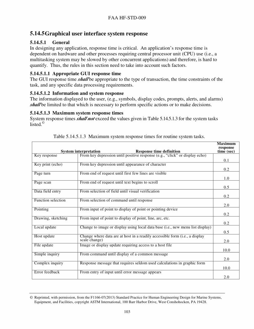
FAA HF-STD-009
© Reprinted, with permission, from the F1166-07(2013) Standard Practice for Human Engineering Design for Marine Systems,
Equipment, and Facilities, copyright ASTM International, 100 Barr Harbor Drive, West Conshohocken, PA 19428.
103
5.14.5 Graphical user interface system response
5.14.5.1 General In designing any application, response time is critical. An application’s response time is dependent on hardware and other processes requiring central processor unit (CPU) use (i.e., a multitasking system may be slowed by other concurrent applications) and therefore, is hard to quantify. Thus, the rules in this section need to take into account such factors.
5.14.5.1.1 Appropriate GUI response time
The GUI response time shall be appropriate to the type of transaction, the time constraints of the task, and any specific data processing requirements.
5.14.5.1.2 Information and system response
The information displayed to the user, (e.g., symbols, display codes, prompts, alerts, and alarms) shall be limited to that which is necessary to perform specific actions or to make decisions.
5.14.5.1.3 Maximum system response times
System response times shall not exceed the values given in Table 5.14.5.1.3 for the system tasks listed.©
Table 5.14.5.1.3 Maximum system response times for routine system tasks.
Maximum response
System interpretation Response time definition time (sec) Key response From key depression until positive response (e.g., “click” or display echo)
0.1 Key print (echo) From key depression until appearance of character
0.2 Page turn From end of request until first few lines are visible
1.0 Page scan From end of request until text begins to scroll
0.5 Data field entry From selection of field until visual verification
0.2 Function selection From selection of command until response
2.0 Pointing From input of point to display of point or pointing device
0.2 Drawing, sketching From input of point to display of point, line, arc, etc.
0.2 Local update Change to image or display using local data base (i.e., new menu list display)
0.5 Host update Change where data are at host in a readily accessible form (i.e., a display
scale change)
2.0 File update Image or display update requiring access to a host file
10.0 Simple inquiry From command until display of a common message
2.0 Complex inquiry Response message that requires seldom used calculations in graphic form
10.0 Error feedback From entry of input until error message appears
2.0
FAA HF-STD-009
© Reprinted, with permission, from the F1166-07(2013) Standard Practice for Human Engineering Design for Marine Systems,
Equipment, and Facilities, copyright ASTM International, 100 Barr Harbor Drive, West Conshohocken, PA 19428.
104
5.14.5.1.4 Maximum system-response time variability
System response time variability shall not exceed 5% when processing in the range of 0 to 2 sec; 10% when processing in the range 2 to 5 sec; and 15% when processing longer than 5 sec.
5.14.5.1.5 Display response time
There shall be no discernible time lag between a change in a system condition being controlled or monitored and its indication on a display.
5.14.5.1.6 Response time from control input to display presentation
The time lag between system response to a control input and display presentation of that response shall be minimized, consistent with safe and effective system operation.
5.14.5.1.7 Acknowledgement of delayed processing
Where system overload or other system conditions will result in a processing delay, the system shall
acknowledge the data entry and provide an indication of the delay to the user. If possible, the system
shall advise the user of the time remaining for the process or of the fraction of the process to be completed.©
5.14.5.1.8 Notification of processing completion
When the processing is time consuming or not otherwise obvious, the system shall notify the user when the processing is complete.
5.14.5.2 Keyboard lockout
5.14.5.2.1 Lockout indication
When an application encounters a keyboard lockout, the application shall provide a clear indication to users when the keyboard is locked out and when it is not. Example: One way this may be done is to change the shape of the cursor or pointer to a watch or hourglass.©
5.14.5.2.2 Response time induced keyboard lockout
If computer processing time requires a delay of concurrent user inputs and no keyboard buffer is available, keyboard lockout shall occur until the computer can accept the next transaction. An alert shall be displayed to indicate to the user that lockout has occurred.©
5.14.5.2.3 Keyboard restoration
When the computer is ready to continue, following a response time induced keyboard lockout, a signal (message) to indicate such shall be presented, (i.e., cursor changes back to a normal shape).©
5.14.5.2.4 Interrupt to end keyboard lockout
When keyboard lockout has occurred, the user shall be able to abort a transaction that has resulted in an extended lockout. A reset prevention capability shall stop the ongoing processing but not RESET the computer, thereby losing prior processing.©

FAA HF-STD-009
© Reprinted, with permission, from the F1166-07(2013) Standard Practice for Human Engineering Design for Marine Systems,
Equipment, and Facilities, copyright ASTM International, 100 Barr Harbor Drive, West Conshohocken, PA 19428.
105
5.14.6 Prompt capability
5.14.6.1 Prompt for needed input A system or application shall prompt users for all required input parameters, request additional or corrected information as needed, provide orientation (as to tasks and processes) during transactions, and indicate any errors that are detected.
5.14.6.2 Prompt usage contexts Prompting shall conform to the following:
a. When operating in special modes, the system shall display the mode designation and file(s) being processed.
b. Before processing any user requests that would result in extensive or final changes to existing data, the system shall require user confirmation.
c. When missing data are detected, the system shall prompt the user. d. When data entries or changes are nullified by an abort action, the user shall be requested
to confirm the abort. e. Neither humor nor admonishment shall be used in structuring messages; the dialog shall
be strictly factual and informative. f. Error messages shall appear as close as possible to the user entry that caused the
message. g. If a user repeats an entry error, the second error message shall be revised to include a
noticeable change so that the user is certain that the computer has processed the attempted correction.©
5.14.6.3 Prompt contents When the computer is waiting for input from a user, it shall indicate clearly where on the screen the input is expected and, to the extent possible, what information is expected.
5.14.6.4 Explicit prompts Prompts and help instructions for system-controlled dialogue shall be explicit. The user shall not be required to memorize lengthy sequences or refer to secondary written procedural references.©
5.14.6.5 Prompt clarity Prompts shall be clear and understandable. They shall not require reference to coding schemes or conventions which may be unfamiliar to occasional users.©
5.14.6.6 Prompts for errors in stacked commands To prompt for corrections of an error in stacked commands, the system shall display the stacked sequence with the error highlighted. Where possible, a procedure shall be provided to correct the error and salvage the stack.©
5.14.6.7 Location of prompts
Prompting messages shall appear in a consistent location on the screen. Example: Prompting could occur at the beginning of the next data entry line, in the data field where an entry is to be made, at a command input line, or within a menu window.©

FAA HF-STD-009
© Reprinted, with permission, from the F1166-07(2013) Standard Practice for Human Engineering Design for Marine Systems,
Equipment, and Facilities, copyright ASTM International, 100 Barr Harbor Drive, West Conshohocken, PA 19428.
106
5.14.7 Feedback
5.14.7.1 Feedback The GUI shall present feedback by way of status, confirmation, and verification information throughout the interaction.
5.14.7.2 Feedback at start-up When the system is not immediately available after system startup, the system shall provide feedback to the user, indicating average system response time or known periods of unavailability, and disable the keyboard and pointing device until startup is complete. The shape of the pointing symbol shall be altered to indicate that it is disabled. When startup is complete and the system becomes available, the system shall remove any messages indicating that it is unavailable, return the pointing symbol to its normal shape, and enable the keyboard and pointing device.
5.14.7.3 Input confirmation feedback Input confirmation shall not trigger removal of displayed data.©
5.14.7.4 Computer response feedback Every user input shall consistently produce some perceptible response. Note: In applications where the system does not produce visual feedback as an indicator of invalid user input, an alternative form of feedback (e.g., different audio sound) shall be used to ensure that the user recognizes the invalid action.©
5.14.7.5 Standby
When system function requires the user to standby, WORKING, BUSY, or WAIT messages
shall be displayed until user interaction is again possible. When a delay is likely to exceed 15 seconds, the user shall be informed. For delays exceeding 60 seconds, a countdown display shall
show the remaining delay time.©
5.14.7.6 Periodic feedback
When the system takes more than 2 seconds to respond, it shall provide periodic feedback to the user indicating that normal operation is occurring.©
5.14.7.7 Delayed computer response When the computer response to a user request is greater than 15 seconds, the computer shall give a clear and positive indication (e.g., an auditory signal) when processing is complete.
5.14.7.8 Feedback for correct input Control feedback responses to correct user input shall consist of changes in state or value of those elements of the displays that are being controlled in an expected and logically natural form. An acknowledgement message shall be used only in those cases in which the more conventional mechanism is not appropriate or feedback response time exceeds 1 second.©
5.14.7.9 Feedback for erroneous input When the system detects control input errors, an error message shall be available and error recovery procedures shall be provided (refer to section 5.14.11 for additional information on Error Management).©

FAA HF-STD-009
© Reprinted, with permission, from the F1166-07(2013) Standard Practice for Human Engineering Design for Marine Systems,
Equipment, and Facilities, copyright ASTM International, 100 Barr Harbor Drive, West Conshohocken, PA 19428.
107
5.14.7.10 Feedback message content Feedback messages shall be self-explanatory. Users shall not be required to translate feedback messages by use of a reference system or code sheets.©
5.14.7.11 Feedback for delayed response to function key activation When the function key activation does not result in an immediately observable response from the computer, the user shall be given another form of acknowledgment or feedback.©
5.14.7.12 Time consuming process notice For time consuming processes (several seconds or more in duration), the system shall give the user warning information before a command is invoked.©
5.14.7.13 Time consuming process abort Users shall be provided with an option to abort time-consuming processes (several seconds or more in duration).©
5.14.7.14 Process outcome
When a control process or sequence is completed or aborted by the system, positive indication
shall be presented to the user concerning the outcome of the process and the requirements for subsequent user action.©
5.14.7.15 Highlighted option acknowledgement Any displayed message or datum selected as an option or input to the system shall be highlighted to indicate acknowledgement by the system.©
5.14.7.16 Rejected input feedback
When the system rejects user input, self-explanatory feedback shall be provided to indicate the reason for rejection and the required corrective action.©
5.14.8 System status
5.14.8.1 System status indication Users shall be provided information on system status on an as requested basis, regarding operational modes, availability, and loads, either automatically or by request.©
5.14.8.2 Status information via active or non-activated display The absence, or non-activated state, of a visual display shall not be relied upon to convey status information (i.e. a darkened display shall not be used to indicate that a piece of equipment is OFF) but is an acceptable indication of the absence of power (that is, POWER OFF) for an operational display but not for maintenance displays.©
5.14.8.3 Equipment status indication When equipment status must be available always to the operator (e.g., STOP/START, ON/OFF), a status indicator shall be provided for each state (i.e., if the operator must know if a piece of equipment is ON or OFF there shall be separate indicators for each condition, one of which must always be lit).©
5.14.8.4 Power failure indication A means of indicating power failure or interruption should be provided.
FAA HF-STD-009
© Reprinted, with permission, from the F1166-07(2013) Standard Practice for Human Engineering Design for Marine Systems,
Equipment, and Facilities, copyright ASTM International, 100 Barr Harbor Drive, West Conshohocken, PA 19428.
108
5.14.9 Routine messages
5.14.9.1 Routine feedback The system shall provide users with consistent, routine feedback regarding such activities as control entries, computer processing, and print requests.
5.14.10 Information suppression recovery
5.14.10.1 Suppression indication When the display of information is temporarily suppressed, an indication of this suppression shall
be provided on the display.
5.14.10.2 Restoration of suppressed information The system shall provide a quick and easy means for restoring suppressed information.
5.14.11 Error management
5.14.11.1 Error messages
5.14.11.1.1 Display of erroneous entries
Upon error detection by the application or system, the GUI shall display an error message and this error message shall be continuously displayed until the error is corrected.©
5.14.11.1.2 Confirmation messages
When a user entry might cause the loss or destruction of data or a disruption of a system, the system shall display a cautionary message and require that the user confirm the entry.©
5.14.11.1.3 Multi-level messages
When appropriate, the system shall provide more than one level of error messages with successive levels providing increasingly detailed explanations.
5.14.11.1.4 Coding of error messages
Messages that require special user attention shall be coded appropriately and distinctively.
5.14.11.1.5 Error message wording
Error messages shall be brief, specific, and task-oriented.
5.14.11.1.6 Specificity of error messages
Error messages shall provide information that pertains specifically to the task in error. Discussion: Make the user aware of the consequences of an action before suggesting that action. For example, say “To delete text, press Enter,” instead of “Press Enter to delete text.”
5.14.11.1.7 Error message tone and phrasing
Error messages shall be constructive and neutral in tone, avoiding phrases that suggest a judgment of the user’s behavior.©
5.14.11.1.8 Error message view
The error messages shall reflect the user’s view, not that of the developer.©
FAA HF-STD-009
© Reprinted, with permission, from the F1166-07(2013) Standard Practice for Human Engineering Design for Marine Systems,
Equipment, and Facilities, copyright ASTM International, 100 Barr Harbor Drive, West Conshohocken, PA 19428.
109
5.14.11.1.9 Error message content appropriate to user training level
Error messages shall be appropriate to the user’s level of training, be as specific as possible to the user’s particular application, and describe a way to remedy, recover, or escape from the error situation.©
5.14.11.1.10 Provision of error recovery information
All conditions and information relevant for users to recover from an error shall be displayed to the user.
5.14.11.1.11 Error message diagnostics information
Error messages shall provide explicit diagnostic information and remedial direction as can be inferred reliably from the error condition. Where clear inference is not possible, probable helpful inference(s) may be offered.©
5.14.11.1.12 Cursor placement
After an error message is displayed, the cursor shall be placed at the location of the error.
5.14.11.1.13 Instructions and error messages
Instructions and error messages shall appear in a consistent location on the screen.©
5.14.11.2 Command interaction handling and error management
5.14.11.2.1 Command editing
A system or application shall permit a user to edit an extended command during its composition before taking an explicit Enter action.
5.14.11.2.2 Command correction prompting
A system or application shall prompt a user to correct an element of a command entry that is not recognized or that is logically inappropriate.
5.14.11.2.3 Faulty commands
Whenever possible, a faulty command shall be retained in the command entry area of the display, with the cursor automatically positioned at the incorrect item and an advisory message displayed that describes the problem and proposes a solution.
5.14.11.2.4 Errors in stacked commands
When an error is detected in a series of stacked command entries, the system shall operate consistently in one of the following modes: (1) execute commands up to the point of error, or (2) require the user to correct any errors before executing any of the commands.
5.14.11.2.5 Partial execution of stacked commands
When only a portion of stacked commands can be executed, the system or application shall
notify the user and provide appropriate guidance to correct, complete, or cancel the command.
5.14.11.2.6 Stacked command execution
When the system detects an error in stacked commands during processing, it shall notify the user and promptly (within 4 seconds) provide guidance to correct, complete, or cancel the stacked commands.

FAA HF-STD-009
© Reprinted, with permission, from the F1166-07(2013) Standard Practice for Human Engineering Design for Marine Systems,
Equipment, and Facilities, copyright ASTM International, 100 Barr Harbor Drive, West Conshohocken, PA 19428.
110
5.15 Help support
5.15.1 Access to and return from help
5.15.1.1 Access and return from help command Users should be able to access Help from within an application, (that is, without leaving the application), and return to where they were before requesting Help.©
5.15.1.2 Single action Users shall be able to access and exit Help with a single action (i.e, a single keystroke or a single click of a pointing device).©
5.15.1.3 Accessing multi-level help When an initial Help display provides only summary information, more detailed explanations
shall be provided in response to repeated user requests for Help.©
5.15.2 Context sensitivity
5.15.2.1 Task-oriented help The information provided in response to a Help request shall be relevant to the task and the current transaction within the task.
5.15.3 Content
5.15.3.1 Titles
Each Help display shall have a title that identifies its contents and reflects the location from which it originated.
5.15.3.2 Content appropriate to user Help information content (wording and level of detail) and format shall be appropriate to the experience and training of the system users.©
5.15.4 Help windows
5.15.4.1 Application help windows Online support shall provide the capability to display a help window for all application windows. Each application window should provide users with access to information about the object with input focus; methods available include context-sensitive help, an information bar in the window, or a Help button that displays a separate help information dialog window.
5.15.4.2 General and function concerning established focus On-line support shall provide the capability for all primary and secondary task-related windows to display general and functional descriptions of an object on which the user establishes focus. This requirement will inform the user of the resulting software response if the object were invoked, and, in cases requiring user input in a certain field, what input is to be supplied and its format.
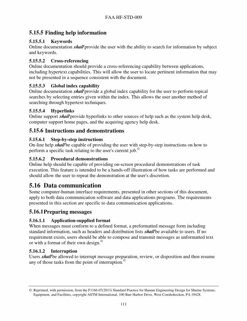
FAA HF-STD-009
© Reprinted, with permission, from the F1166-07(2013) Standard Practice for Human Engineering Design for Marine Systems,
Equipment, and Facilities, copyright ASTM International, 100 Barr Harbor Drive, West Conshohocken, PA 19428.
111
5.15.5 Finding help information
5.15.5.1 Keywords Online documentation shall provide the user with the ability to search for information by subject and keywords.
5.15.5.2 Cross-referencing Online documentation should provide a cross-referencing capability between applications, including hypertext capabilities. This will allow the user to locate pertinent information that may not be presented in a sequence consistent with the document.
5.15.5.3 Global index capability Online documentation shall provide a global index capability for the user to perform topical searches by selecting entries given within the index. This allows the user another method of searching through hypertext techniques.
5.15.5.4 Hyperlinks
Online support shall provide hyperlinks to other sources of help such as the system help desk, computer support home pages, and the acquiring agency help desk.
5.15.6 Instructions and demonstrations
5.15.6.1 Step-by-step instructions On-line help shall be capable of providing the user with step-by-step instructions on how to perform a specific task relating to the user's current job.©
5.15.6.2 Procedural demonstrations Online help should be capable of providing on-screen procedural demonstrations of task execution. This feature is intended to be a hands-off illustration of how tasks are performed and should allow the user to repeat the demonstration at the user's discretion.
5.16 Data communication Some computer-human interface requirements, presented in other sections of this document, apply to both data communication software and data applications programs. The requirements presented in this section are specific to data communication applications.
5.16.1 Preparing messages
5.16.1.1 Application-supplied format When messages must conform to a defined format, a preformatted message form including standard information, such as headers and distribution lists shall be available to users. If no requirement exists, users should be able to compose and transmit messages as unformatted text or with a format of their own design.©
5.16.1.2 Interruption Users shall be allowed to interrupt message preparation, review, or disposition and then resume any of those tasks from the point of interruption.©

FAA HF-STD-009
© Reprinted, with permission, from the F1166-07(2013) Standard Practice for Human Engineering Design for Marine Systems,
Equipment, and Facilities, copyright ASTM International, 100 Barr Harbor Drive, West Conshohocken, PA 19428.
112
5.16.1.3 Incorporate existing files Users shall be allowed to incorporate, or “attach” an existing data file in a message or to combine several files into a single message for transmission, and to combine stored data with new data when preparing messages for transmission. It shall not be necessary to re-enter any data already entered for other purposes.©
5.16.2 Sending messages
5.16.2.1 Notification of unsuccessful transmission Users shall be notified if a message could not be transmitted.©
5.16.2.2 Originator identification Except for broadcast communication systems, the transmitter of each message in inter-user communications shall be identified—automatically, if possible.©
5.16.2.3 Data preservation
The arrival of a message in a format incompatible with the system shall not result in the loss of the message or of any ongoing transaction.©
5.16.2.4 Transmission notification Users shall be notified if a message could not be transmitted. When possible, notification of failure to transmit a message should include an explanation of the failure.©
5.16.2.5 Address entry prompt When users must specify the address for messages, prompting shall be provided to guide the user in the process.©
5.16.2.6 Address directory Users should be able to select addresses from a directory for automatic entry in address fields. Users should be able to search for addresses in a directory by specifying a complete or partial name or other address information.©
5.16.3 Receiving messages
5.16.3.1 Incoming message control Users should be able to specify “filters” based on message source, priority, type, or content that will control the notification of incoming messages. Users should be able to choose the device (files, display, printer) that will receive messages.©
5.16.3.2 Incoming message notice While using the system, users should be notified when they receive a new message.©
5.16.3.3 Unobtrusive notice The notice of arrival of an electronic message should not interfere with ongoing system use.©

FAA HF-STD-009
113
6 Notes
6.1 Intended use This standard is intended for use in acquisition of maintenance tools and systems for FAA Tech Ops and for systems acquired for Air Traffic Operations that will be maintained and/or monitored by Tech Ops. Non-Government standards or commercial item descriptions should be used to describe the requirements for commercially available items.
6.2 Tailoring Tailoring is the process of selecting and evaluating individual requirements to determine the extent to which they apply to a specific system or piece of equipment. It includes the process of modifying these requirements to ensure that there is an optimal balance between operational needs and cost. To ensure proper application of this standard, invitation for bids, when generating requests for proposals, and contractual statements of work, the requirements in sections 4 and 5 of this standard should be tailored to exclude any unnecessary requirements.
6.2.1 General guidance Design requirements, such as those contained in this document, must be generally worded so that they may be applied to various system applications. Before they can be applied to a specific system or piece of equipment, these generally worded requirements may need to be converted into system-specific rules. For example, a requirement may originally state that the options in a menu should be ordered in a way that minimizes user navigation, but it may have to be rewritten for a specific system so that it specifies an exact order of items. This process is known as tailoring. Tailoring requirements may not always be possible. If the specifics of a system are not known in advance, a section of this standard may need to be cited in its entirety, with tailoring occurring later in the process.
6.2.2 Tailoring to reduce cost Not every requirement contained within this document will be applicable to every system. The application of every requirement within this document to a single system would likely result in a system that would be cost prohibitive. Tailoring the requirements contained within this document to ensure applicability to a specific system avoids unnecessary efforts, overly restrictive design, and exorbitant costs.
6.2.3 Joint responsibility Ideally, it should be the joint responsibility of human factors experts, vendors or system developers, users, and program managers to tailor design requirements. In order to tailor requirements, the members of this working coalition must have a thorough understanding of task requirements and user characteristics. Each of these groups has something unique to contribute to the process. Users have knowledge of the task, people from the program office and vendors have knowledge of the costs involved in implementing recommendations, and human factors experts have knowledge of human factors. Together, these representatives can determine which items will provide the most benefit overall.

FAA HF-STD-009
114
6.2.4 Process As a first step in requirements tailoring, a human factors practitioner must review the sections of this document to identify those requirements that are relevant to the acquisition being considered. For a complex system, or one with many components, the list of relevant requirements may be extensive. Once all relevant requirements have been identified on a general level, they should be reviewed to decide which specific ones are most appropriate for the particular system or equipment.
7 Concluding Material
7.1 Preparing activity This document was prepared by the FAA Human Factors Division (ANG-C1) for the FAA Air Traffic Organization’s Technical Operations (AJW-0/AJW-131). Federal Aviation Administration Human Factors Division ANG-C1 800 Independence Ave SW Washington, DC 20591 Federal Aviation Administration Air Traffic Organization, Technical Operations (AJW-0/AJW-131) 600 Independence Ave SW Washington, DC 20591
7.2 Review activities Questions on this document should be addressed to ANG-C1, 800 Independence Ave., SW, Washington, DC 20591, or emailed using the form under Contact Us at www.hf.faa.gov.

FAA HF-STD-009
115
APPENDIX A: Acronyms and Abbreviations ATO Air Traffic Organization CPU Central Processor Unit FAA Federal Aviation Administration FFOV Forward Field of View GUI Graphical User Interface NAS National Airspace System Q&A Questions and Answers Tech Ops Technical Operations
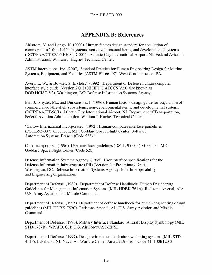
FAA HF-STD-009
116
APPENDIX B: References
Ahlstrom, V. and Longo, K. (2003). Human factors design standard for acquisition of commercial-off-the-shelf subsystems, non-developmental items, and developmental systems (DOT/FAA/CT-03/05 HF-STD-001). Atlantic City International Airport, NJ: Federal Aviation Administration, William J. Hughes Technical Center. ASTM International Inc. (2007). Standard Practice for Human Engineering Design for Marine Systems, Equipment, and Facilities (ASTM F1166- 07). West Conshohocken, PA. Avery, L. W., & Bowser, S. E. (Eds.). (1992). Department of Defense human-computer interface style guide (Version 2.0, DOE HFDG ATCCS V2.0 also known as DOD HCISG V2). Washington, DC: Defense Information Systems Agency. Birt, J., Snyder, M.,, and Duncanson,, J. (1996). Human factors design guide for acquisition of commercial-off-the-shelf subsystems, non-developmental items, and developmental systems (DOT/FAA/CT-96/1). Atlantic City International Airport, NJ: Department of Transportation, Federal Aviation Administration, William J. Hughes Technical Center. "Carlow International Incorporated. (1992). Human-computer interface guidelines (DSTL-92-007). Greenbelt, MD: Goddard Space Flight Center, Software Automation Systems Branch (Code 522)." CTA Incorporated. (1996). User-interface guidelines (DSTL-95-033). Greenbelt, MD: Goddard Space Flight Center (Code 520). Defense Information Systems Agency. (1995). User interface specifications for the Defense Information Infrastructure (DII) (Version 2.0 Preliminary Draft). Washington, DC: Defense Information Systems Agency, Joint Interoperability and Engineering Organization. Department of Defense. (1989). Department of Defense Handbook: Human Engineering Guidelines for Management Information Systems (MIL-HDBK-761A). Redstone Arsenal, AL: U.S. Army Aviation and Missile Command. Department of Defense. (1995). Department of defense handbook for human engineering design guidelines (MIL-HDBK-759C). Redstone Arsenal, AL: U.S. Army Aviation and Missile Command. Department of Defense. (1996). Military Interface Standard: Aircraft Display Symbology (MIL-STD-1787B). WPAFB, OH: U.S. Air Force/ASC/ENSI. Department of Defense. (1997). Design criteria standard: aircrew alerting systems (MIL-STD-411F). Lakehurst, NJ: Naval Air Warfare Center Aircraft Division, Code 414100B120-3.

FAA HF-STD-009
117
Department of Defense. (1998). Defense information infrastructure (DII) common operating environment (COE) office automation software requirements specification (SRS) (Version 3.3). Falls Church, VA: Defense Information Systems Agency/DIICOE.
Department of Defense. (2003). Common operating environment (COE) user interface specifications (UIS) (Version 4.3). Falls Church, VA: Defense Information Systems Agency Center for Standards, Global Information Grid Enterprise Services Directorate.
Department of Defense. (2012). Department of defense design criteria standard: human engineering (MIL-STD-1472G). Redstone Arsenal, AL: U.S. Army Aviation and Missile Command.
Department of Transportation. (1997). Human factors design guide for acquisition of commercial-off-the-shelf subsystems, non-developmental items, and developmental systems (HFDG Version 1.1). Atlantic City International Airport, NJ: Federal Aviation Administration, William J. Hughes Technical Center.
Department of Transportation. (2007). Standard practice: baseline requirements for color use in air traffic control displays (HF-STD-002). Atlantic City International Airport, NJ: Federal Aviation Administration, William J. Hughes Technical Center.
Friedman-Berg, F., Allendoerfer, K., and Pai, S. (2008). Air traffic control display standard: a standardized color palette for terminal situation displays (DOT/FAA/TC-08/15). Atlantic City International Airport, NJ: Federal Aviation Administration, William J. Hughes Technical Center.
Gantthead. (2007). User interface standards for GUI screen design (Unattributed web document). Downloaded from http://www.gantthead.com.
General Services Administration. (2000). Electronic and information technology accessibility standards. In the federal register 65 (246): 80500-80528. Washington, DC.: General Services Administration, Architectural and Transportation Barriers Compliance Board.
National Aeronautics and Space Administration. (2011). NASA space flight human-system standard Volume 2: Human Factors, Habitability, and Environmental Health (NASA-STD-3001). Washington, DC.
NUREG-0700 Human-System Interface Design Review Guidelines. Revision 2, U.S. Nuclear Regulatory Commission, Office of Nuclear Regulatory Research, Washington, D.C. March 2002.
Schumacher Jr., R. (1996). Ameritech graphical user interface standards and design guidelines (Issue 14-100). Canton, GA: Ameritech Services, LLC.
Smith, S., and Mosier, J. (1986). Guidelines for designing user interface software (technical report no. ESD-TR-86-278). The MITRE Corporation, Bedford, Massachusetts.
U.S. Department of Energy. (2001). Human factors/ ergonomics handbook for design for ease of maintenance. (Parts 1-3. Also known as DOE-HDBK-1140-2001). Washington, DC: U.S. Department of Energy/Area HFAC.
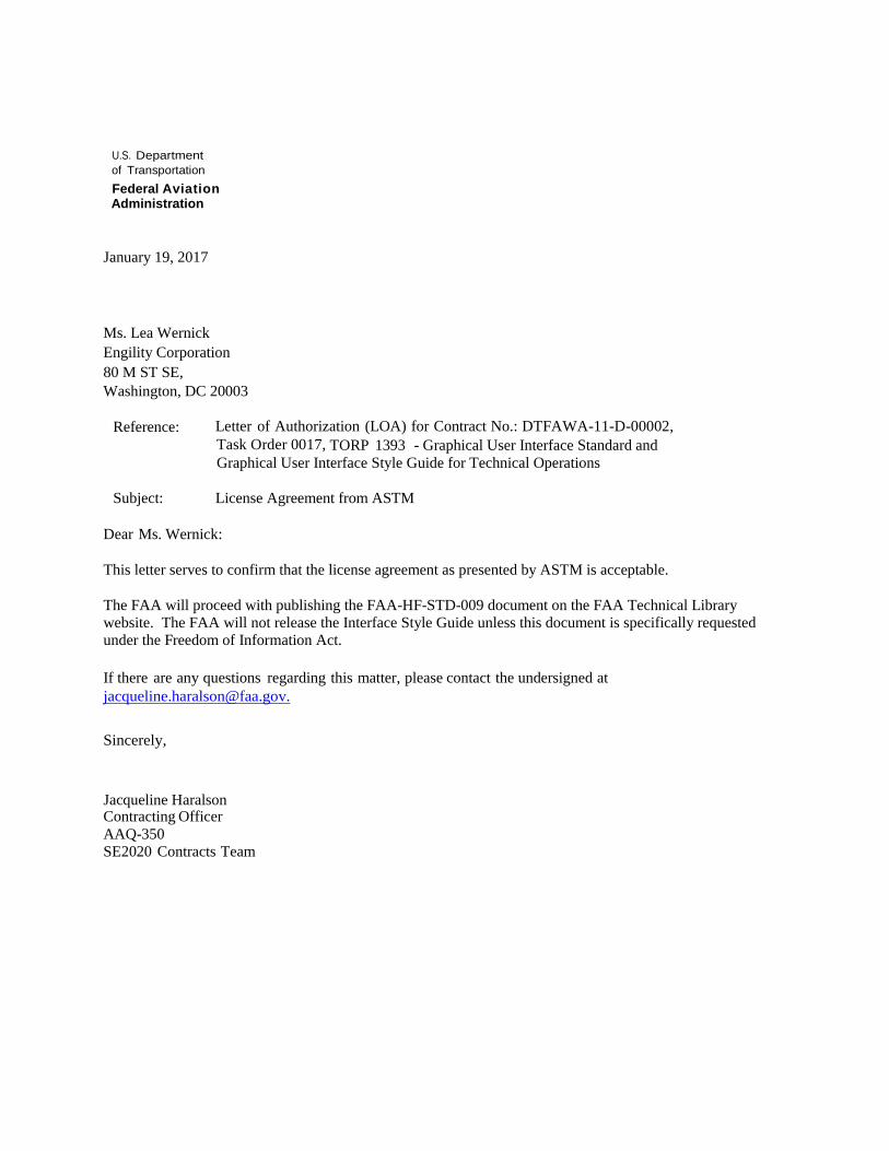
U.S. Department of Transportation Federal Aviation Administration
January 19, 2017
Ms. Lea Wernick Engility Corporation 80 M ST SE, Washington, DC 20003
Reference: Letter of Authorization (LOA) for Contract No.: DTFAWA-11-D-00002, Task Order 0017, TORP 1393 - Graphical User Interface Standard and Graphical User Interface Style Guide for Technical Operations
Subject: License Agreement from ASTM
Dear Ms. Wernick:
This letter serves to confirm that the license agreement as presented by ASTM is acceptable.
The FAA will proceed with publishing the FAA-HF-STD-009 document on the FAA Technical Library website. The FAA will not release the Interface Style Guide unless this document is specifically requested under the Freedom of Information Act.
If there are any questions regarding this matter, please contact the undersigned at [email protected].
Sincerely,
Jacqueline Haralson Contracting Officer AAQ-350 SE2020 Contracts Team


ASTM 1166 Requested Permissions
ASTM F1166
Content Section
GUI designers shall focus on presenting the user with essential information required to conduct operational tasks in an organized,
uncluttered, and uncomplicated manner. Additionally, the dynamic interaction shall be simplified. 13.1.1.1
GUI interaction designs shall reflect established standard procedures and user expectations in order to maintain acceptable
performance and limit human errors. The goal for effective interface design is for the user to be able to anticipate system
responses and operate/navigate a system in a timely fashion and with minimal training.
13.1.1.3
The GUI design shall reflect formal analyses of system functions and tasks to ensure that the interface provides all of the
functionality and information required for the user to perform tasks. Critical to providing task-oriented design is limiting the
interaction (both user supplied actions to the system and information fed to the user) to information essential for the specified
task.
13.1.1.4
The GUI sha ll present information to a user in a directly usable form; the user shall not have to decode, interpret, transpose,
compute, interpolate, or mentally translate data into other units, number bases, or languages. 6.1.3
The user shall not have to rely on memory to interpret new data; each data display shall provide needed context, including
recapitulating prior data from prior displays as necessary. 13.4.3.1
GUI developers shall keep information density in the display to the minimum necessary for critical task sequences. A minimum of
one-character space shall be left blank vertically above and below critical information, with a minimum of two character spaces
left blank horizontally before and after.
13.4.2
An analysis of user tasks should drive the design of the display screen layout, including display partitioning, paging, scrolling, and
inter-frame considerations.13.1.6
For signals or displays that frequently or consistently change their outputs, the information displayed shall be displayed for a
sufficient duration to be reliably detected under expected user workload and operational environment. 6.1.9
The GUI shall present information legibly, anticipating all reasonble viewing conditions and with due consideration given to
ambient lighting and viewing distance. 6.1.12
Displays of quantitative information shall include units of measure. 6.1.13
Arrangements of pushbutton in the form of keyboards shall be used when alphabetic, numeric, or special function information is
to be entered into a system.13.27.2
Touchscreen control may be used to provide an overlaying control function to a data display where direct visual reference access
and optimum direct control access are desired. a. Touchscreens are appropriate for interactions involving the selection of
devices or targets on position displays (e.g., radars), arrangement diagrams, piping diagrams, discretefunction controls, or
opening/closing valves. b. Touchscreens may be used to complete intermittent actions such as gross cursor navigation and
communication panel selection.
13.27.5
The pointing device selected for an application should be the one that most appropriately meets the application requirements
and is most cost effective. When present, a pointing device shall be capable of the following: a. Moving a pointer on the screen, b.
Selecting objects on which the pointer is placed, and c. Drag and drop operations.
13.27.6
The selection or activation process should be invoked by pressing a button on the pointing device. If the device has only one
button, that button should provide the “select” function. If the device has two buttons, the left button should provide the “select”
function and the right button should access a “menu” function. The system shall provide users with the ability to reverse the left-
right operation functions of the buttons.
13.27.6.4
Data entry functions shall be designed to establish consistency of data entry transactions, minimize input actions and memory
load on the user, ensure compatibility of data entry with data display, and provide the user flexible control of data entry. 13.11.1
The system shall enable the user to manipulate data without concern for internal storage and retrieval mechanisms of the
system. 13.12.11
In printing text, users shall be able to select among available output formats (e.g., line spacing, character size, margin size,
heading, and footing) and to specify the pages of a document to be printed. 13.11.22
Form fill-in as a means of data entry is appropriate if some flexibility is needed (i.e., the inclusion of optional as well as required
items), if users will have had moderate training, or if computer response time is slow. The form fill-in interaction style is
intended for a different set of users than command language; namely non-expert users. Form fill-in interfaces can be especially
useful for routine, clerical work or for tasks that require a great deal of data entry. The form fill-in style is also known as “fill-
inthe-blanks”.
13.16.1
The format and content of displayed forms should follow, in every major parameter, the paper form it is intended to represent. 13.16.3
Fields or groups of fields shall be separated by spaces, lines, or other delineation cues. Required fields shall be distinguished from
optional fields13.16.4
Field labels shall be distinctively presented such that they can be distinguished from data entry. Labels for data entry fields shall
incorporate additional cueing of data format where the entry is made up of multiple inputs (e.g., DATE (MM/DD/YYYY): _ _ / _ _ /
_ _ _ _)
13.16.4.1
A displayed cursor shall be positioned, by the system, at the first data entry field when the form is opened initially. 13.16.4.2
Using the tab key shall advance the cursor to the next data entry field when the user has completed entry of the current field. 13.16.4.2
No-entry (protected) areas of the display shall be designated as such and made inaccessible to the user via the cursor. 13.6.6
Displayed forms shall be arranged such that related items are grouped together. 13.16.2
When required data entries have not been entered, the omission shall be indicated to the user and either immediate or delayed
entry of the missing items shall be allowed. However, a delayed entry should be avoided, when possible. If necessary, the user
shall be required to designate the field to indicate that the missing item is delayed, not overlooked.
13.16.5
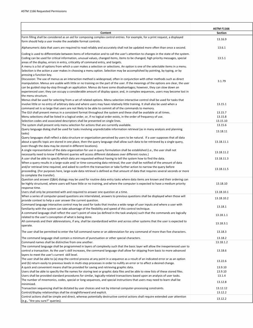
ASTM 1166 Requested Permissions
ASTM F1166
Content Section
Form filling shall be considered as an aid for composing complex control entries. For example, for a print request, a displayed
form should help a user invoke the available format controls. 13.16.9
Alphanumeric data that users are required to read reliably and accurately shall not be updated more often than once a second. 13.6.1
Coding is used to differentiate between items of information and to call the user’s attention to changes in the state of the system.
Coding can be used for critical information, unusual values, changed items, items to be changed, high priority messages, special
areas of the display, errors in entry, criticality of command entry, and targets.
13.5.1
A menu is a list of options from which a user makes a selection or selections. An option is one of the selectable items in a menu.
Selection is the action a user makes in choosing a menu option. Selection may be accomplished by pointing, by typing, or by
pressing a function key.
Discussion: The use of menus as an interaction method is widespread, often in conjunction with other methods such as direct
manipulation. Menus are usable with little or no training on the part of the user. If the meanings of the options are clear, the user
can be guided step-by-step through an application. Menus do have some disadvantages; however, they can slow down an
experienced user; they can occupy a considerable amount of display space; and, in complex sequences, users may become lost in
the menu structure.
3.1.79
Menus shall be used for selecting from a set of related options. Menu selection interactive control shall be used for tasks that
involve little or no entry of arbitrary data and where users may have relatively little training. It shall also be used when a
command set is so large that users are not likely to be able to commit all of the commands to memory.
13.15.1
The GUI shall present menus in a consistent format throughout the system and these shall be available at all times. 13.15.7
Menu selections shall be listed in a logical order, or, if no logical order exists, in the order of frequency of use. 13.15.8
Selection codes and associated descriptors shall be presented on single lines. 13.15.10
The system shall present only menu selection for actions that are currently available. 13.15.6
Query language dialog shall be used for tasks involving unpredictable information retrieval (as in many analysis and planning
tasks) 13.18.11
Query languages shall reflect a data structure or organization perceived by users to be natural. If a user supposes that all data
about a specific topic are stored in one place, then the query language shall allow such data to be retrieved by a single query,
even though the data may be stored in different locations).
13.18.11.1
A single representation of the data organization for use in query formulation shall be established (i.e., the user shall not
necessarily need to know if different queries will access different databases over different routes.) 13.18.11.2
A user shall be able to specify which data are requested without having to tell the system how to find the data. 13.18.11.3
When a query results in a large-scale and/ or time-consuming data retrieval, the user shall be notified of the amount of data
and/or retrieval time required, and asked to confirm the transaction or take further action to narrow the query before
proceeding. (For purposes here, large-scale data retrieval is defined as that amount of data that requires several seconds or more
to complete the transfer).
13.18.11.5
Question and answer (Q&A) dialogs may be used for routine data entry tasks where data items are known and their ordering can
be highly structured, where users will have little or no training, and where the computer is expected to have a medium priority
response time.
13.18.10
Users shall only be presented with and required to answer one question at a time. 13.18.10.1
When a series of computer-posed questions are interrelated, answers to previous questions shall be displayed when those will
provide context to help a user answer the current question. 13.18.10.2
Command language interactive control may be used for tasks that involve a wide range of user inputs and where a user with
familiarity with the system can take advantage of the flexibility and speed of this control technique. 13.18.1
A command language shall reflect the user’s point of view (as defined in the task analysis) such that the commands are logically
related to the user’s conception of what is being done. 13.18.1.1
All commands and their abbreviations, if any, shall be standardized within and across other systems that the user is expected to
operate. 13.18.3.1
The user shall be permitted to enter the full command name or an abbreviation for any command of more than five characters. 13.18.3
The command language shall contain a minimum of punctuation or other special characters. 13.18.2
Command names shall be distinctive from one another. 13.18.1.2
The command language shall be programmed in layers of complexity such that the basic layer will allow the inexperienced user to
control a transaction. As the user’s skill increases, the command language shall allow for skipping from basic to more advanced
layers to meet the user’s current skill level.
13.18.6
The user shall be able to (a) stop the control process at any point in a sequence as a result of an indicated error or as an option
and (b) return easily to previous levels in multi-step processes in order to nullify an error or to affect a desired change. 13.22.6
A quick and convenient means shall be provided for saving and retrieving graphic data. 13.9.10
Users shall be able to specify the file names for storing text or graphic data files and be able to view lists of these stored files. 13.9.10
Users shall be provided standard procedures for similar, logically-related transactions based upon an analysis of user tasks. 13.1.4
The number of mnemonics, codes, special or long sequences, and special instructions that users may need to learn shall be
minimized. 13.12.8
Transaction sequencing shall be dictated by user choices and not by internal computer-processing constraints. 13.12.12
Control/display relationships shall be straightforward and explicit. 13.12.2
Control actions shall be simple and direct, whereas potentially destructive control actions shall require extended user attention
(e.g., “Are you sure?” queries). 13.12.2

ASTM 1166 Requested Permissions
ASTM F1166
Content Section
13.14.19.2
Systems using cursors shall provide cursor control capability consistent with user speed and accuracy requirements. Additionally,
the user should be able to adjust the sensitivity of the cursor movement to be compatible with the required task. Note: The
user’s ability to adjust the sensitivity of the cursor movement shall be provided only where adjustment of this control could not
adversely affect the ability to fulfill the mission and complete critical tasks.
13.28.1
The user shall have the capability to perform the following operations on open windows: move, resize, hide (or minimize),
activate, deactivate, scroll, and zoom.13.14.1.1
Users should be able to perform the following operations on objects in an information window: a. Select an object with the
pointing device. b. Select an object using the keyboard. c. Move an object to another location in the same window. d. Move an
object to a different window. e. Copy an object for placement at a different location within the same window. f. Copy an object
for placement in a different window. g. Paste an object previously copied from this or another window. h. Undo/redo the last
action.
13.14.1.1
Window controls shall be accessible via a pointing device and a keyboard. 13.14.1.4
Window controls, such as “open” and “close” shall operate consistently on all windows. 13.14.11
Task-related elements and functions shall be located together in one window, or on one page within the same window if the
window includes multiple pages. 13.14.7.3
Windows shall be designed so that users do not need to: a. Switch back and forth between windows or pages when performing a
task, or b. Remember information from one window or page while viewing another window or page13.14.7.3
Windows shall be presented initially in a form that is most appropriate for user task performance. 13.14.1.2
When there is a need to view different types of data simultaneously, the user shall be able to display and select separate windows
on a single screen. 13.14.1
Each window shall have a default location at which the window appears when it is first opened. Initial placement should be based
on the importance of the information in that window and information in other visible windows that should not be obscured.
When a window is first displayed, input focus shall be placed on defaul object
13.14.3
The windows in an application and related applications shall have a consistent organizational scheme for the key elements of the
windows.13.14.7
Information in windows should be organized in some recognizable, logical, and consistent form to facilitate scanning and
assimilation.13.14.7
Information in a window should be grouped according to principles obvious to the user (e.g., mission, task, system function, or
sequence) based on the user’s requirements when performing an ongoing task. 13.14.7.1
Related graphics in a window shall be aligned unless position is intended to indicate a spatial or functional relationship. 13.14.7.2
The GUI shall provide adequate information, and respond within the required time limits with sufficient detail and precision to
ensure mission accomplishment13.25.1
The GUI shall minimize user task complexity, simplify control inputs to the extent possible, particularly for tasks requiring real-
time responses, and permit logical task completion with a minimum number of control actions.13.25.4
Where users are required to enter data into a system, an easy means shall be provided for correcting erroneous entries, including
correcting individual errors without requiring the user to reenter correctly entered commands or data elements13.22.1
A capability shall be provided to detect and correct errors after keying in a command or data but before entering the information
into the system. While it is desirable that errors be detected early, error checking shall occur at logical data entry breaks (i,e,, at
the end of data fields rather than character by character) to avoid disrupting the user.
13.22.2
User errors shall be minimized by using internal software checks of user entries for validity of item, sequence of entry,
completeness of entry, and range of value. 13.22.3
All user error corrections shall be acknowledged by the GUI, either by indicating a correct entry has been made or by displaying
another error message (i.e., in the event that the error correction attempt was inadequate).13.22.8
The GUI shall allow a user to return to previous steps in a transaction sequence in order to correct an error or make any other
desired change. 13.22.6
The user shall be able to stop the control process at any point in a sequence as a result of an indicated error or as an option. The
user shall be able to return easily to previous levels in multistep processes to nullify an error or to effect a desired change. 13.22.6
The system shall require the user to acknowledge critical entries (e.g., Exit, Close, or Delete) prior to their being implemented by
the system.13.22.4
Alarm and alert system signals shall be unambiguous, with a clear indication of the cause for the alarm or alert. 8.1.4.1
Users shall be provided on-line, context-sensitive help that includes the following: definitions of allowable options, system
capabilities, procedures, and ranges of values upon user request. Discussion: On-line Help should include the following
components: a. Memory aids, b. Basic information likely to be of use only to novices, c. Material selected from written
documentation, d. Explanations that elaborate on the written documentation, e. Information that might seem obvious but may
not be so to all users, f. Step-by-step instructions on how to perform the most common tasks, and g. Instructions for access to
outside help.
13.1.10,
13.24.3
A single, standard action (e.g., single keystroke or click on a pointing device) that is always available shall be provided to request
help13.24.2
On-line documentation, off-line documentation, and help instructions shall use consistent terminology. 13.20.6
Users shall be permitted to browse and search through On-line Help displays, just as they would through a printed manual, to
gain familiarity with system functions and operating procedures.13.24.5
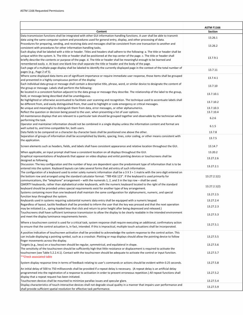
ASTM 1166 Requested Permissions
ASTM F1166
Content Section
Data transmission functions shall be integrated with other GUI information-handling functions. A user shall be able to transmit
data using the same computer system and procedures used for general entry, display, and other processing of data. 13.26.1
Procedures for preparing, sending, and receiving data and messages shall be consistent from one transaction to another and
consistent with procedures for other information-handling tasks. 13.26.2
Each display shall be labeled with a title or header. Titles and headers shall adhere to the following: a. The title or header shall be
unique within the system. b. The title or header shall be positioned at the top center of the page. c. The title or header shall
briefly describe the contents or purpose of the page. d. The title or header shall be meaningful enough to be learned and
remembered easily. e. At least one blank line shall separate the title or header and the body of the page.
13.7.9.1
Each page of a multiple-page display shall be labeled to identify the currently displayed page in the context of the total number of
pages (e.g., Page 2 of 5). 13.7.11
Where some displayed data items are of significant importance or require immediate user response, those items shall be grouped
and presented in a highly conspicuous portion of the display13.7.4.1
Each individual data group or message shall contain a descriptive title, phrase, word, or similar device to designate the content of
the group or message. Labels shall perform the following: 13.7.10
Be located in a consistent fashion adjacent to the data group or message they describe. The relationship of the label to the group,
field, or message being described shall be unambiguous. 13.7.10.1
Be highlighted or otherwise accentuated to facilitate user scanning and recognition. The technique used to accentuate labels shall
be different from, and easily distinguished from, that used to highlight or code emergency or critical messages.13.7.10.2
Be unique and meaningful to distinguish them from data, error messages, or other alphanumerics. 13.7.10.3
Reflect the question or decision being posed to the user, when presenting a list of user options. 13.7.10.4
All maintenance displays that are relevant to a particular task should be grouped together and observable by the technician while
performing the task.6.2.6
Operator and maintainer information should not be combined in a single display unless the information content and format are
well suited to, and time-compatible for, both users. 6.1.5
Data fields to be compared on a character-by-character basis shall be positioned one above the other. 13.7.8
Separation of groups of information shall be accomplished by blanks, spacing, lines, color coding, or other means consistent with
the application. 13.7.5
Screen elements such as headers, fields, and labels shall have consistent appearance and relative location throughout the GUI. 13.14.7
When applicable, an input prompt shall have a consistent location on all displays throughout the GUI. 13.20.2
Graphical representations of keyboards that appear on video displays and enlist pointing devices or touchscreens shall be
designed as following. 13.27.2.6
Discussion: The key configuration and the number of keys are dependent upon the predominant type of information that is to be
entered into the system. Keyboard layouts can take several forms that aid entry of such information.13.27.2.1
The configuration of a keyboard used to enter solely numeric information shall be a 3 X 3 + 1 matrix with the zero digit entered on
the bottom row and arranged using the standard calculator format: “789 456 123”. If the keyboard is used primarily for
communications, the “telephone” arrangement – with the numerals 1, 2, and 3 in the top row – shall be used.
13.27.2.1(1)
QWERTY keyboards, rather than alphabetical order keyboards, with the numeric keyboard located to the right of the standard
keyboard should be provided unless special requirements exist for another type of key arrangement. 13.27.2.1(2)
Systems containing more than one keyboard shall maintain the same configuration for alphanumeric, numeric, and special
function keys throughout the system.13.27.2.5
Keyboards used in systems requiring substantial numeric data entry shall be equipped with a numeric keypad. 13.27.2.4
Regardless of layout, tactile feedback shall be provided to inform the user that the key was pressed and that the next operation
may be initiated (i.e., spring-loaded keys that click and return to prior height after being depressed and released.) 13.27.2.3
Touchscreens shall have sufficient luminance transmission to allow the display to be clearly readable in the intended environment
and meet the display luminance requirements herein.13.27.5.3
Where a touchscreen control is used for a critical task, system response shall require executing an additional, confirmatory action
to ensure that the control actuation is, in fact, intended. If this is impractical, multiple touch actuations shall be incorporated. 13.27.5.1
A positive indication of touchscreen activation shall be provided to acknowledge the system response to the control action. This
can include displaying a pointing symbol, such as a crosshair. Plotting or map displays should allow the pointing device to follow
finger movements across the display.
13.27.5.5
Targets (e.g., keys) on a touchscreen should be regular, symmetrical, and equilateral in shape. 13.27.5.6
The sensitivity of the touchscreen should be sufficiently high that little resistance or displacement is required to activate the
touchscreen (see Table 5.2.2.4.1). Contact with the touchscreen should be adequate to activate the control or input function.
**Check associated table
13.27.5.7
System display response time in terms of feedback relating to user’s commands or actions should be evident within 0.25 seconds. 13.27.5.8
An initial delay of 500 to 750 milliseconds shall be provided if a repeat delay is necessary. (A repeat delay is an artificial delay
programmed into the registration of a response to activation in order to prevent erroneous repetition.) All repeat functions shall
display that a repeat request has been initiated.
13.27.5.2
Touchscreen devices shall be mounted to minimize parallax issues and specular glare. 13.27.5.4
Display characteristics of touch-interactive devices shall not degrade visual quality in a manner that impairs user performance and
shall provide sufficient spatial resolution for effective task performance. 13.27.5.9
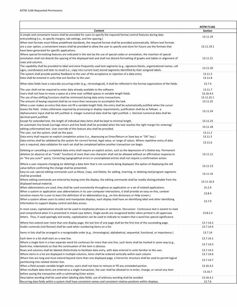
ASTM 1166 Requested Permissions
ASTM F1166
Content Section
A simple and convenient means shall be provided for users to specify the required format control features during data
entry/editing (i.e., to specify margins, tab settings, and line spacing.) 13.11.19
When text formats must follow predefined standards, the required format shall be provided automatically. Where text formats
are a user option, a convenient means shall be provided to allow the user to specify and store for future use the formats that
have been generated for specific applications.
13.11.19.1
Where special formatting features are indicated in the text by the use of special codes or annotation, the insertion of special
annotation shall not disturb the spacing of the displayed text and shall not disturb formatting of graphs and tables or alignment of
rows and columns
13.11.21
The capability shall be provided to label and store frequently used text segments (e.g., signature blocks, organizational names, call
signs, coordinates) and later to recall (i.e., copy into current text) stored segments identified by their assigned labels.13.11.20
The system shall provide positive feedback to the user of the acceptance or rejection of a data entry. 13.11.3
Data shall be entered in units that are familiar to the user. 13.11.8
When data fields have a naturally occurring order (e.g., chronological), it shall be reflected in the format organization of the fields. 13.7.4
The user shall not be required to enter data already available to the software. 13.11.7
Users shall not have to move a space at a time over unfilled spaces in variable length fields. 13.16.4.5
The use of key-shifting functions shall be minimized during data entry transactions. 13.11.25.1
The amount of keying required shall be no more than necessary to accomplish the task. 13.11.25
When a user makes an entry that does not fill a variable length field, the entry shall be automatically justified when the cursor
leaves the field. Unless otherwise required by processing or display requirements, justification shall be as follows: a.
Alphanumeric input shall be left justified. b. Integer numerical data shall be right justified. c. Decimal numerical data shall be
decimal-point justified.
13.11.24
Except for extended text, the length of individual data items shall be kept to minimal length. 13.11.23
An automatic line break (carriage return and line feed) shall be provided when the text reaches the right margin for entering/
editing unformatted text. User override of this feature also shall be provided. 13.11.18
The user, not the system, shall set the pace. 13.11.2
Data entry shall require an explicit completion action (i.e., depressing an Enter/Return or Save key or “OK” key.) 13.11.5
Data entries shall be validated by the system for correct format, legal value, or range of values. Where repetitive entry of data
sets is required, data validation for each set shall be completed before another transaction can begin. 13.11.6
Deleting or cancelling a completed data entry shall require an explicit action, such as the depression of a Delete key. Permanent
deletion (in absence of an “Undo” function) of more than one character shall not be allowed without an affirmative response to
an “Are you sure?” query. Correcting typographical errors in uncompleted entries shall not require a confirmation action.
13.11.12
Where a user requests changing (or deleting) a data item that is not currently being displayed, the option of displaying the old
value before confirming the change shall be presented. 13.11.13
Easy-to-use, special editing commands such as Move, Copy, and Delete, for adding, inserting, or deleting text/program segments
shall be provided. 13.11.16
Where editing commands are entered by keying onto the display, the editing commands shall be readily distinguishable from the
displayed textual material. 13.11.16.4
When abbreviations are used, they shall be used consistently throughout an application or a set of related applications. 15.2.4
When a system or application uses abbreviations in its user-computer interactions, it shall provide an easy on-line, context-
sensitive means for a user to learn the definition of an abbreviation (e.g., on-line dictionary or Help screen.) 13.8.4
When a system allows users to select and manipulate displays, each display shall have an identifying label and other identifying
information to support display control and data access. 13.7.9
In most cases, capitalization should not be used to emphasize phrases or sentences. Discussion: Continuous text is easiest to read
and comprehend when it is presented in mixed case letters. Single words are recognized better when printed in all uppercase
letters. Thus, if used sparingly and wisely, capitalization can be used to indicate to readers that a word has special significance.
13.8.2.4
Where lists extend over more than one display page, the last line of one page shall be the first line of the succeeding page. 13.7.14.2
Arabic numerals (not Roman) shall be used when numbering items on a list. 13.7.14.4
Items in lists shall be arranged in a recognizable order (e.g., chronological, alphabetical, sequential, functional, or importance.) 13.7.14
Each item in a list shall start on a new line. 13.7.14.1
Where a single item in a two separate word list continues for more than one line, such items shall be marked in some way (e.g.,
blank line, indentation) so that the continuation of the item is obvious. 13.7.14.3
Rows and columns shall be labeled distinctively to facilitate data entry, with data entered in units familiar to the user. 13.7.14.5
Where items in a list are displayed in multiple columns, items shall be ordered vertically within each column 13.7.14.6
Where lists are long and must extend beyond more than one displayed page, a hierarchic structure shall be used to permit logical
partitioning into related shorter lists. 13.7.14.7
When a field accepts variable length entries, users shall not have to remove or fill any unneeded portion. 13.16.4.5
When multiple data items are entered as a single transaction, the user shall be allowed to re-enter, change, or cancel any item
before saving the transaction with a culminating Enter action. 13.16.7
Descriptive wording shall be used when labeling data fields; use of arbitrary wording shall be avoided. 13.16.4.1
Recurring data fields within a system shall have consistent names and consistent relative positions within displays. 13.7.6

ASTM 1166 Requested Permissions
ASTM F1166
Content Section
When a field entry involves a unit of measurement, the unit shall be included as part of the label or field. Examples: COST:
$_____.__ LENGTH (ft): __________ 13.16.4.6
When the dimensional unit varies for a given field, it shall be provided, or selected, by the user. 13.16.4.6
The maximum acceptable length for variable length fields shall be indicated. 13.16.4.3
Tabular data displays shall be used to present row-column data. 13.7.13
Location of recurring data shall be similar among all tabular data displayed and common throughout the system. 13.7.13.1
Adequate separation shall be provided between columns and between groups of rows. 13.7.6.3
Example: To increase readability, insert at least three spaces between columns and a blank line after every fifth row. 13.7.6.4
Column spacing within a table shall be uniform and consistent. 13.7.16.2
In tabular display, the units of displayed data shall be consistently included in the column labels. 13.7.16.1
For editing programs or tabular data, cursor tab controls or other provisions for establishing and moving readily from field to field
shall be provided. 13.11.16.3
Map displays shall be large enough to permit the simultaneous presentation and visual integration required by users. 13.9.25
When a map or other graphic display has been expanded from its normal presentation, an indicator of the scale expansion shall
be provided13.9.21
When users need to compare graphic data across a series of charts, the same scale shall be used for each chart. 13.9.21.1
Where graphic data entry involves frequent pointing on a display surface, the user interface shall provide display control and
sequence control by pointing to minimize shifts from one entry device to another. For example, in drawing a flow chart, a user
shall be able to link elements or points directly by pointing at them or drawing lines between rather than by separately keyed
entries.
13.9.6
Zooming shall be available to change the scale of textual and graphic information when it exceeds the available display area in the
window. Zoom functions shall be provided for changing scale both continuously and in discrete steps. 13.14.16
Graphic displays that require visual integration of changing patterns shall be updated at the maximum refresh rate of the display
device consistent with the user’s capacity to process the information. 13.9.3
The current cursor position on a displayed graphic shall be indicated with a distinctive cursor symbol at that point (i.e., a plus sign,
representing abbreviated crosshairs whose intersection can mark a position with reasonable precision.) 13.9.7
Users shall be provided the means to designate and selec displayed graphic elements for manipulation such as by pointing where
a pointing device is provided for line-drawing purposes.13.9.9
During graphic data entry, users shall be allowed to specify attributes for displayed elements (e.g., text font, plotting symbol, line
type) by selecting from displayed samples illustrating the available options.13.9.9.1
During graphic data entry/editing, the selected attributes that will affect current actions shall be displayed for ready reference as
a reminder of current selections in effect. 13.9.9.2
An easy and convenient means shall be provided for saving and retrieving graphic displays for their possible reuse. The user shall
be allowed to designate filenames of his or her choice for the stored graphic data. 13.9.10
The computer shall provide automatic registration or alignment of computer-generated graphic data, so that variable data are
shown properly with respect to fixed background or data map at any display scale. 13.9.11
Where graphic data must be plotted in predefined standard formats (e.g., target areas on maps, flight plans), templates or
skeletal displays shall be provided for those formats to aid data entry.13.9.12
When graphic data can be derived from data already available in the computer, machine aids for that purpose shall be provided. 13.9.13
When line drawing is required, users shall be provided with aids for drawing straight line segments. When line segments must join
or intersect, computer aids shall be provided to aid in such connection13.9.14
When a user must draw figures, computer aids shal l be provided for that purpose. 13.9.14.1
When lines or figures must be drawn to represent numeric coordinates, computer aids should include templates for entering the
coordinates, and if necessary, selecting the appropriate units for those coordinates. 13.9.14.2
When editing graphic data, users shall be provided with the capability to change the size (scale) of any selected element on the
display, rather than delete and recreate the element in a different size. 13.9.15
When a user’s attention must be directed to a portion of a graphic display showing critical or abnormal data, that feature shall be
highlighted with some distinctive means of data coding. 13.9.16
When a user must compare graphic data to some significant level or critical value, a reference index or baseline shall be included
on the display. 13.9.17
When precise reading of a graphic display is required, the capability shall be provided to supplement the graphic representation
with the actual numeric values. 13.9.18
The labels on dynamic graphic displays shall remain with the top of the label up when the displayed image rotates. 13.9.19
Pictorial symbols (e.g., icons, pictograms) shall look like the objects, features, or processes they represent and shall consist of a
graphic image and an identifying label. When images are used to identify controls, status indicators, or other programmatic
elements, the meaning assigned to those images shall be consistent throughout an application and across related applications.
13.9.20
Where graphs are presented, only a single scale shall be shown in each axis, rather than including different scales for different
curves in the graph. If interpolation must be made or where accuracy is required when reading graphic data, computer aids shall
be provided to the user.
13.9.21.2
When grid lines are displayed, they shall be unobtrusive and shall not obscure data elements. The user shall have the option to
display or suppress grid lines. 13.9.22

ASTM 1166 Requested Permissions
ASTM F1166
Content Section
Graphic lines shall be no less than 1⁄4 pt. Graphic lines should contain a minimum of 50 resoluQon elements per inch, which will
give the user a sense of continuity. 13.9.4
Where users must evaluate the difference between two sets of data, that difference shall be plotted directly as a curve in its own
right. Users shall not have to visually compare the curves that represent the original data sets. 13.9.23
Bar graphs shall be used for comparing a single measure across a set of several entities or for a variable sampled at discrete
intervals. 13.9.24
Adjacent bars shall be spaced closely enough, normally not more than one bar width, so that a direct visual comparison can be
made without eye movement. 13.9.24.1
Histograms (bar graphs without spaces between the bars) shall be used where bar graphs are required and where a great many
intervals must be plotted.13.9.24.2
Color can be helpful in differentiating classes of information in complex, dense, and critical displays. Users often express a
preference for color, even when it does not improve their performance. Although it may improve motivation and memory,
performance advantages associated with the use of color tend to be highly task dependent.
13.5.7
Symbol coding may be used to enhance information assimilation from data displays. Symbols shall be analogs of the event or
system element they represent or be consistent and well known to the users. Where size difference between symbols is used, the
major dimensions of the larger shall be at least 150 % of the major dimension of the smaller with a maximum of three size levels
permitted.
13.5.6
When special symbols are used to signal critical conditions, they shall be used for only that purpose only. 13.5.6.1
Flash coding shall be used to call the user’s attention to mission critical events only. No more than 2 flash rates shall be used.
Where one rate is used, the rate shall be 3–5 flashes per second. Where two rates are used, the second rate shall be not greater
than 2 per second. The flash rate duty cycle should have a 50 % on- and 50 % off-cycle.
13.5.2
The maximum acceptable length for variable length fields shall be indicated. 13.16.4.3
Data entry shall not be expected to require overwriting a set of characters in a field (such as a default). 13.16.4.4
When a consistent dimensional unit is used in a given entry field, the dimensional unit shall be provided by the computer. When
the dimensional unit varies for a given field, it shall be provided, or selected, by the user. 13.16.4.6
When multiple data items are entered as a single transaction, the user shall be allowed to reenter, change, or cancel any item
before taking a final Enter action. 13.16.7
Descriptive wording shall be used when labeling data fields. Use of arbitrary codes shall be avoided. 13.16.4.1
Where source documents or external information are not available, forms shall be designed so that data items are ordered in a
logical sequence for data entry.13.16.8
Each page of options (menu) shall have a title that clarifies the purpose of that menu. 13.15.3
An indication of the user's current position in a hierarchical menu structure shall be provided 13.15.15
A user shall be able to return to the top-level menu from anywhere in a hierarchical menu structure with one simple control
action. 13.15.17
A user shall be able to return to the next higher-level menu (back menu) from anywhere in a hierarchical menu structure with one
simple control action. 13.15.16
If several levels of hierarchical menus are provided, a direct function call capability shall be provided such that the experienced
user does not have to step through multiple menu levels. 13.15.11
When menu traversal can be accomplished by clearly defined hierarchical paths, the user shall be given some indication of the
displayed menu’s current position in the overall or relevant structure, e.g., an optional display of “path” information or
cascading menus. A menu tree showing the menu hierarchy shall be included in the user manual or online Help.
13.15.15
Pop-up menus can be very useful in data entry. They can present to a user the permissible entries for a field, thus eliminating the
need for the user to remember the entries, preventing invalid entries, and eliminating potential typing errors. A pop-up menu
resembles a pull-down menu, but is not associated with the top-level menus listed in the menu bar.
13.5.1.1(4)
When system users have different linguistic backgrounds, graphic menus may be used which display icons to represent the
control options. Where the system is intended for use by foreign personnel, icon design s hall be consistent with applicable
cultural and ethnic variables to ensure comprehension and to avoid potential offense.
13.13.2
Where design constraints do not permit pointing devices, a standard window shall be provided for the user to key the selected
option code. 13.15.2
Once a key has been assigned a given function, it shall not be reassigned to a different function. 13.27.3
Except when used to toggle between two opposing states, a fixed function key shall require only a single action to accomplish its
function. 13.27.3.5
Non-active fixed function keys shall be replaced by a blank key or grayed-out. 13.27.3.3
Fixed function keys shall be logically grouped and placed in distinctive locations on the keyboard. 13.27.3.4
When fixed function key activation does not result in an immediately observable natural response, the user shall be given an
indication of system acknowledgment.13.27.3.6
Fixed function key assignments shall be displayed at all times, shall be displayed by direct marking, and, where abbreviations are
necessary for fixed function keys, standard abbreviations shall be used.13.27.3.7
Prolonged depression of function keys shall not repeat the function, except for the Delete key. 13.27.3.8
Variable function keys may be used for programmable menu selection and for entering control functions. A single entry on a
variable function key shall not produce a critical action. Critical actions shall require confirmation when initiated with a variable
function key.
13.27.4
Shift keys shall not be required to operate variable function keys. 13.27.4.4

ASTM 1166 Requested Permissions
ASTM F1166
Content Section
Provisions shall be made for easy re-labeling of variable function keys. 13.27.4.3
When the effect of a function key varies, the status of the key shall be displayed. 13.27.4.1
When keys with labeled default functions are reprogrammed or turned off, a visual signal shall signal the user that the standard
function is not currently accessible via that key.13.27.4.2
When the functions assigned to a set of keys change as a result of user selection, it shall be easy for the user to return them to
the initial, base level functions.13.27.4.5
Dialog types shall be compatible with anticipated task requirements and user skills. 13.12.9
Each display shall provide a command entry area that is located consistently across displays (i.e., at the bottom of the screen. 13.8.4
Spelling and other common errors shall not produce valid system commands or initiate transactions different from those
intended. The system shall recognize common misspellings of commands by informing the user of the unrecognized entry and
providing a similar correct entry for revision and approval by the user. Computer-corrected commands, values, and spellings shall
be displayed and highlighted for user confirmation.
13.22.9
When executing a command that might result in deleting or modifying data or other potentially adverse consequences, the
system or application shall inform the user of the nature of the consequence and request that the user confirm the command
unless an Undo command is available.
13.18.9
The user shall be able to request prompts, as necessary, to determine required parameters or available options for an appropriate
next command entry.13.18.5
The programming shall not accept a user designated macro name that is the same as an existing command name. 13.18.7
The capability shall be provided to allow the user to specify a string of text (words, phases, or numbers) to advance (or back up)
the cursor automatically to the next occurrence of that string.13.11.17
The query language shall be designed to include logic elements that permit users to link (e.g., “and”, “or”) sequential queries as a
single entry.13.18.11.4
A display freeze mode shall be provided to allow close scrutiny of any selected frame that is updated or advanced automatically
by the system. For frozen display frames, an option shall be provided to allow resumption at the point of stoppage or at the
current real-time point.
13.6.3
When a display is frozen, its frozen status shall be clearly indicated. 13.6.4
Where text has been specified to become the subject of control entries (i.e., it has been selected for underlining, bolding, moving,
copying, or deleting), the affected segment of text shall be highlighted to indicate its boundaries.13.11.16.5
When hierarchical levels are used to control a process or sequence, the number of levels shall be kept few in number. 13.12.7
When hierarchical levels are used, display and input formats shall be similar within levels. 13.12.7
When hierarchical levels are used, the system shall indicate the current position within a sequence. 13.12.7
Controls shall be compatible with the lowest anticipated skill level for the potential user. 13.12.4
Provision shall be made to prevent accidental actuation of potentially destructive control actions, including the possibility of
accidental erasure or memory dump.13.12.3
When numeric data are displayed or required for control input, such data shall be in the decimal, rather than binary, octal,
hexadecimal, or other number system. Note: When numeric data is not displayed in the decimal format due to operational
requirements, the alternate number system used shall be clear to the user.
13.12.10
The presence and location of control input data entered by the user shall be clearly and appropriately indicated. Data displayed
shall not mislead the user with regard to nomenclature, units of measure, sequence of task steps, or time phasing.13.12.14
Control actions to be selected from a discrete set of alternatives shall have those alternatives displayed before the time of
selection. The current value of any parameter or variable with which the user is interacting shall be displayed. User control inputs
shall result in a positive feedback response displayed to indicate performance of requested actions.
13.12.6
An icon shall consist of a graphic image and an identifying label. 13.9.20
When images are used to identify controls, status indicators, or other programmatic elements, the meaning assigned to those
images shall be consistent throughout an application and across related applications.13.9.20
The selectable area of an icon shall be large enough to reduce the risk of error and increase the user’s ease in selecting the icon. 13.13.4
The selectable area or hot spot outside of the area of the icon shall be at least 4 millimeters. The selectable area in which a user
can place the pointer and successfully select an icon is often called the hot spot.13.13.4
Icons shall be positioned at least 10 millimeters apart from each other, as measured from perimeter to perimeter. 13.13.4.1
Lists and palettes are both effective ways of allowing users to access options. Palettes can be used in selecting icons, patterns,
colors, characters, or drawings. They allow the user to select an action or attribute from a group of icons fixed in a window.
Palettes can be fixed or floating.
13.13.5
A push button shall have either a text or graphic label. 13.13.6
The states of a pushbutton shall be distinguishable for the user by appearance. 13.13.6.1
Default pushbutton shall be clearly distinguishable from other pushbutton. 13.13.6
Radio buttons (also known as exclusive buttons or option buttons) are single, two-state choices, which are mutually exclusive
from each other.13.13.7
Radio buttons shall be used if it is required that one and only one of a set of mutually exclusive options be selected. 13.13.7
A box should be drawn around a group of radio buttons to visually separate the group from other interface features. When a
specific option is not available, it should be displayed as subdued or grayed-out in relation to the brightness of the available
options.
13.13.7.1
An individual radio button shall always be part of a mutually exclusive group of two or more radio buttons. 13.13.7
A radio button that is active shall cause all of the other radio buttons in its group to be inactive. 13.13.7

ASTM 1166 Requested Permissions
ASTM F1166
Content Section
A user shall be able to select a radio button using a pointing device by moving the pointer onto the radio button and clicking the
appropriate device button.13.13.7
A user shall be able to select a radio button using the keyboard by moving a location cursor to the desired button (i.e., using the
arrow keys) and pressing the Enter key.13.13.7
Labels shall be provided for each set of radio buttons. 13.13.7.1
Check boxes shall be provided if a user may select multiple (or none) of the available options. 13.13.8
Users shall be able to toggle selected and unselected states on a check box using either a pointing device or the keyboard. 13.13.8
Check boxes shall have two states, selected and unselected. 13.13.8
Labels shall be provided for each set or group of check boxes and for each individual check box in the set or group. 13.13.8.1
Check boxes shall be arranged in logical order so that the most frequently used boxes are at the top or at the left, depending on
how the check boxes are oriented.13.13.8.1
Sliders are appropriate and should be used when users must set a value within a fixed range and the precise value is less
important than relative position.13.13.9
Slider designs shall contain the following components: a. A slider shall have a movable marker that indicates the current setting
and a line or rectangular area along which it moves. b. A slider shall have a label or title that indicates the purpose of the slider.
When appropriate, the slider should provide a numerical readout of the current setting. Discussion: Tick marks and numeric
values may be added to the line or rectangular area of the slider.
13.13.9.1
Users shall be able to change the setting of a slider by moving the pointer onto the marker and dragging it. 13.13.9
A movable cursor within the display shall have a distinctive visual attribute that does not obscure other displayed entities. When
fine positioning accuracy is required, as in some forms of graphic and image processing applications, the displayed cursor shall
include an appropriate point designation feature (such as crosshairs). The cursor shall not move beyond the display boundaries
and disappear from sight. If the cursor is moved by depressing a key, releasing the key shall cause the cursor to stop moving.
13.28.2.1
13.28.2.2
13.28.2.3
The home position for the cursor shall be consistent across similar types of displays. 13.28.3
The response of a cursor to control movements shall be consistent, predictable, and compatible with the user's expectations. For
cursor control by key action, the cursor shall move in the corresponding direction of the arrow key that was pressed (i.e., left
arrow to left, right arrow to right, up arrow up, down arrow down). For cursor control by joystick, movement of the control shall
result in the cursor moving in the corresponding direction (i.e., left movement moves cursor to the left, right movement to the
right, push movement up, and pull movement down).
13.28.7
The means shall be provided to readily move the cursor to the head or the foot (end) of the file. 13.28.8
Where cursor positioning is incremental by discrete steps, the step size of cursor movement shall be consistent horizontally (that
is, in both right and left directions) and vertically (in both up and down directions).13.28.5
When position designation is required in a task emphasizing keyed data entry, cursor control shall be by some device integral to
the keyboard. If cursor movement is accomplished by depressing keys, the keys shall be located on the main keyboard.13.28.6
A separate, explicit action, distinct from cursor position, shall be required for the actual entry (for example, enabling, actuation) of
a designated position. For most graphics data entry, pointing shall be a dual action, with the first action positioning the cursor at a
desired position and the second action confirming that position to the computer. An exception may be a design allowing
“freehand” drawing of continuous lines where the computer must store and display a series of cursor positions as they are
entered by the user.
13.28.4
Data deletion or cancellation shall require an explicit action, such as depressing a Delete key. Permanent deletion (in absence of
an “Undo” function) of more than one character shall not be allowed without an affirmative response to an “Are you sure?” type
of query.
13.11.12
When a window first receives input focus, the text cursor shall be placed in the text area where typing is most likely to occur. 13.14.3
When fine positioning accuracy is required, as in some forms of graphic and image-processing applications, the displayed cursor
shall include an appropriate point designation feature (such as crosshairs).13.28.2.3
A well-defined on-screen indication of the current focus shall be provided that moves among interactive interface elements as the
input focus changes.13.14.12
A pointer shall have a hot spot, that is, an active point (although this active point may not be readily apparent to the user) to
indicate the precise location where an operation will occur. These points are specified for a variety of pointer shapes in Figure
5.12.9.15.5
13.27.6.1
An application shall redefine the shape of a pointer only when the pointer is inside an application window (including the border). 13.27.6.1
The screen location of a hot spot shall not change if the pointer changes from one shape to another. 13.27.6.1
When no adequate pointer shape exists, such as those depicted in Figure 5.12.9.16.5, a new pointer should be created. Table 33
All windows shall contain a title bar, located at the top of the window, which provides a title and access to all of the controls
available to the open window. The titles of subordinate (secondary) windows shall correlate with the menu selection items from
the main window menu.
13.14.8
Scrollbars shall be used to view textual or graphic information when it exceeds the available display area in the window and shall
not be used, or disabled if all information can be viewed simultaneously. Vertical (top-to-bottom) scrolling is usually preferred
over horizontal (left-to-right) scrolling.
13.14.15
If used, a horizontal scrollbar shall appear at the bottom of the window and a vertical scrollbar shall appear on the right side of
the window.13.14.15.1

ASTM 1166 Requested Permissions
ASTM F1166
Content Section
A scrollbar shall contain two symbols that allow a user to move forward or backward through the entire document one page at a
time.13.14.15.2
Menu bars shall be used only in primary windows. There shall be no more than one menu bar in a given window. The menu bar
shall be located at the very top of the application area and extend the full width of the window.13.14.17
Default pushbutton shall be clearly distinguishable from the other pushbutton using visual features such as highlighting or
appearing three dimensional.13.13.6
All pushbutton in a window should have the same size and shape. 13.13.6
A push button shall have a consistent text or graphic label that should describe the results of pressing the button and reflect the
action that will be taken by the application rather than the user.13.13.6
An application shall use one or more primary windows for the performance of primary operational task(s) and secondary windows
to present supplementary or supporting data related to a primary task(s). Secondary windows may include message windows or
windows for short-term interactions related to subtask or functional control or message windows for presenting messages to
users.
13.14.2
Every application with a user interface shall initially display a primary window. A primary window shall be displayed as soon as the
application starts.13.14.2.1
The usage of secondary windows should be limited. The default size of a secondary window shall be as small as possible to convey
the needed information.13.14.2.2
When a user has finished making entries in a data-entry window, he or she shall be able to save the entries by taking an explicit
action such as selecting a Save menu option or activating an Apply or OK push button.13.11.5
Message windows shall contain a title, a message, and one or more pushbutton. They should also contain information and
options for user interaction. If it is necessary to view information in other windows while viewing a message box, the message
window shall be movable.
13.14.19
Alarm (warning) and alert (caution) windows and other message windows shall be front most on the display. 13.14.3.1
Users shall not be able to minimize or resize message windows. 13.14.19.1
Destructive actions shall be preceded by a user confirmation (at least one extra step) in a message window. 13.14.19.2
The control buttons used to enter a command from a message window shall be located consistently at the bottom of the message
window. The default button shall be consistently located on the left side of the message window. The button with the opposing
action shall be located on the right side. Any additional control buttons shall be located between the default and opposing action
buttons.
13.14.19.4
In message windows, the default control button shall be a non-destructive button, such that it would be activated only if an
operator presses Enter. The default button shall be highlighted (i.e., by adding an extra border around it.)13.14.19.3
Messages that are critical or that require user acknowledgment (e.g., error messages) shall appear in their own dialog boxes. 13.7.9.2
The default size for a window should be large enough to present all relevant information for the task, not obscure important
information, not cause crowding or visual confusion, and minimize the need for scrolling. The size of the initial presentation of a
window shall be consistent with its contents (i.e., the amount of information to be displayed, number of menus, data fields, etc.)
13.14.14.1
Users shall be able to open a window with a single action. The action that opens a window shall automatically make that window
active.13.14.11.1
A window that is open and active shall be capable of receiving input from a user. 13.14.12
An open window shall be completely visible on the screen at the time it is opened and when it is active. Discussion: More than
one window can be opened on a screen at the same time. An open window may be partially or totally obscured by another open
window; that is, an open window may or may not be visible.
13.14.12.2
When multiple windows are open simultaneously, the user shall have the capability to tile, layer, or sequentially view the
windows easily. Tiling shall automatically size all open windows equally and position them side-by-side vertically, horizontally, or
in a tiled pattern within the available virtual display area. Cascading (or layering) shall automatically lay windows on top of each
other such that the title bar of each window is visible and the top window is active.
13.4.4
The control system shall maintain a list of all open windows and their statuses (including any that are hidden) and shall provide a
user interface to this list. Users shall be able to identify, access, and control all open windows easily from this list, upon request.13.14.6.1
Users shall be able to close a window with a single action. Closing a window shall remove it from the screen and cease all
processing in that window. A pop-up window shall appear to request user confirmation of a closing action when closing a window
that contains unsaved data or ongoing processes. The user shall have the option to cancel the close action, to complete/halt any
ongoing processing or to save data.
13.14.11.2
When a primary window is closed by the user, all associated subordinate (secondary) windows and message windows shall also
close. Closing a secondary window shall not affect the primary (parent) window.13.14.11.3
Only one window at a time shall be active. 13.14.12
When two or more windows are located in the same part of the display (that is, overlap), the window that was most recently
active shall be shown in front of the other windows and the overlapped portions of the other window(s) shall not be shown. An
obscured window shall become fully visible when it is made active.
13.14.12.2
An active window shall be distinguishable from inactive windows. Exception: Complex situations may occur where one window
has input focus for keyboard and mouse inputs and another window has input focus for voice entries.13.14.12
When a user activates a window, all other windows shall become inactive, although there may still be operations (i.e., background
processing) occurring in the inactive windows.13.14.12
Discussion: An inactive window continues to be displayed on the screen but may be obscured by other windows. 13.14.12.1

ASTM 1166 Requested Permissions
ASTM F1166
Content Section
When a window becomes inactive, it shall lose input focus. 13.14.12.1
The system shall alert the user to critical information that becomes available in a hidden or inactive window. 13.14.1.5
Regardless of the number of windows open in an application, only one window at a time (the active window) shall be able to
receive input from a pointing device or the keyboard.13.14.12
Users shall be able to assign input focus to any open window of the current application either with a pointing device or from the
keyboard.13.14.12
When a window first appears, the location cursor or highlighting shall be placed on the object that users are most likely to select,
for example, a text field or a default push button.13.14.3
A user shall be able to move the input focus among objects in the window using either the pointing device or the keyboard. 13.14.12
For each system or application, the window operations that are performed shall be identified and their manner of execution
made consistent throughout the system.13.14.11
The minimum window size shall be tall enough to display the title bar, classification bar, status bar, menu bar, and border. It shall
be wide enough to display the window title, border, and any window controls. The default height of windows containing textual
information and windows used for scanning data shall be large enough to display at least four lines of text. The default width for a
window containing textual information shall be large enough to display 50 to 80 characters.
5.14.14.3
Where applicable, a user shall be able to minimize the window by moving the pointer onto the Minimize control in the title bar
and clicking the appropriate button or by selecting Minimize from the window menu or control menu.13.14.14.5
Where applicable, a user shall be able to minimize the window using the keyboard by selecting Minimize from the window menu. 13.14.14.5
The maximum window size shall not exceed the display area of a single display device. When a window is maximized, it shall be
relocated to a fixed position on the display device. The entire title bar and application area shall be visible in the maximized state.13.14.14.4
When the user clicks on the Maximize button, the application shall enlarge the window to its largest size or to encompass the
entire display screen, whichever is smaller.13.14.14.4
Where applicable, the application shall provide a Close operation that enables a user to close a window, that is, to remove it from
the screen and stop processing operations associated with the window.13.14.11.2
When processing is occurring or when unsaved data have been generated in the window, users shall be required to confirm the
Close action before the window is removed from the screen and processing stops.13.14.11.2
Where applicable, the application shall provide a Move operation that enables a user to move a window on the screen. 13.14.13
When a window is movable and a pointing device is available, a user shall be able to move the window by moving the pointer into
the window title bar, pressing the appropriate button on the pointing device, and dragging the window to its new location.
Discussion: As the user moves the pointing device, the window or an outline of the window will move on the screen to the new
location once the button is released.
13.14.13
If multiple display screens are used, users shall be able to move a window between screens by dragging the window from one
screen to another.13.14.13.1
The user shall never be able to move a window off the display so that it cannot be seen. 13.14.13
The user shall be allowed to change the size of windows to any value between the minimum and the maximum defined. Users
shall be able to change the horizontal and vertical dimensions of a window independently or together. The contents of a window
shall remain visible during the resizing.
13.14.14
Resizing a window shall not result in the textual information being resized to scale. When resized, the graphics in the window shall
remain the same size, while the scope of the graphics being shown shall change. The relative position of the data and the controls
within the borders of a window shall not change when a window is resized.
13.14.14.2
Navigation between windows shall reflect an obvious logic based on task requirements, which should be easy for users to
understand. Windows should be designed to facilitate easy access between related windows or related pages within a window.13.14.5
The user shall have several easy means to shift among all open windows. Default methods of shifting among open windows will
be clicking a mouse button and using function keys.13.14.6
Window design shall avoid the use of hypertext links for navigation. 13.14.6.3
A user shall not have to reenter data already entered in the current task session. 13.26.5
In applications where users must log on to the system, log on shall be a separate procedure that must be completed before a user
can select among any operational options.13.2.1
Where multiple users have simultaneous access to computer control or output, the operation by one person shall not interfere
with the operation of another unless mission survival necessitates pre-emption.13.25.5
Appropriate prompts for log on shall be displayed automatically by the GUI without requiring a special action other than turning
on the computer.13.2.1.1
Users shall be provided feedback relevant to the log on procedure that indicates the status of the log on. 13.2.1.2
If a user cannot log on to a system, a prompt shall be provided to explain the reason for the inability. Log on processes shall
require minimum input from the user consistent with the requirements prohibiting illegal entry.13.2.1.3
13.2.2
13.12.1.1
Table 30
13.11.4
13.12.1.2
13.12.1.2

ASTM 1166 Requested Permissions
ASTM F1166
Content Section
13.12.1.3
13.12.1.4
13.20.1
13.20.1.1
13.20.1.2
13.20.1.3
13.20.1.4
13.20.1.5
13.20.1.6
13.20.1.7
13.20.3
13.20.4
13.22.10
13.20.2
13.19.4
13.1.5
13.19.2
13.28.9
13.12.13
13.12.13.1
13.19.8
13.27.3.6
13.19.9
13.14.11.2
13.19.3
13.19.6
13.19.8
13.1.9
6.1.1.2
6.1.1.3
13.22.11
13.20.1.2
13.22.5
13.22.5
13.22.5
13.22.7
13.7.9.2
13.24.6
13.24.2
13.24.4
13.24.7
13.24.3.6
13.26.3
13.26.4
13.26.5
13.26.7
13.12.15
13.26.10
13.26.7
13.26.8
13.26.8.1
13.26.9
13.26.9.1
13.26.9.1


![[4910-13] DEPARTMENT OF TRANSPORTATION Federal Aviation Administration Pilot, Flight ... · 2019. 10. 14. · 1 [4910-13] DEPARTMENT OF TRANSPORTATION Federal Aviation Administration](https://static.fdocuments.in/doc/165x107/5ff742da8730ff39c81a8a50/4910-13-department-of-transportation-federal-aviation-administration-pilot-flight.jpg)