U.S. DEPARTMENT OF TRANSPORTATION …. DEPARTMENT OF TRANSPORTATION Maritime Administration ......
117
Process Analysis Via Accuracy Control U.S. DEPARTMENT OF TRANSPORTATION Maritime Administration in cooperation with Todd Pacific Shipyards Corporation
Transcript of U.S. DEPARTMENT OF TRANSPORTATION …. DEPARTMENT OF TRANSPORTATION Maritime Administration ......
0 1 4 3
NDARDS THE NATIONAL
February 1982
Process AnalysisVia Accuracy Control
RESEARCHPROG RAM
U.S. DEPARTMENT OF TRANSPORTATIONMaritime Administrationin cooperation withTodd Pacific Shipyards Corporation

Report Documentation Page Form ApprovedOMB No. 0704-0188
Public reporting burden for the collection of information is estimated to average 1 hour per response, including the time for reviewing instructions, searching existing data sources, gathering andmaintaining the data needed, and completing and reviewing the collection of information. Send comments regarding this burden estimate or any other aspect of this collection of information,including suggestions for reducing this burden, to Washington Headquarters Services, Directorate for Information Operations and Reports, 1215 Jefferson Davis Highway, Suite 1204, ArlingtonVA 22202-4302. Respondents should be aware that notwithstanding any other provision of law, no person shall be subject to a penalty for failing to comply with a collection of information if itdoes not display a currently valid OMB control number.
1. REPORT DATE FEB 1982 2. REPORT TYPE
3. DATES COVERED 00-00-1982 to 00-00-1982
4. TITLE AND SUBTITLE Process Analysis Via Accuracy Control
5a. CONTRACT NUMBER
5b. GRANT NUMBER
5c. PROGRAM ELEMENT NUMBER
6. AUTHOR(S) 5d. PROJECT NUMBER
5e. TASK NUMBER
5f. WORK UNIT NUMBER
7. PERFORMING ORGANIZATION NAME(S) AND ADDRESS(ES) Naval Surface Warfare Center CD,Code 2230 -Design IntegrationTower,9500 MacArthur Blvd Bldg 192 Room 128,Bethesda,MD,20817-5700
8. PERFORMING ORGANIZATIONREPORT NUMBER
9. SPONSORING/MONITORING AGENCY NAME(S) AND ADDRESS(ES) 10. SPONSOR/MONITOR’S ACRONYM(S)
11. SPONSOR/MONITOR’S REPORT NUMBER(S)
12. DISTRIBUTION/AVAILABILITY STATEMENT Approved for public release; distribution unlimited
13. SUPPLEMENTARY NOTES
14. ABSTRACT
15. SUBJECT TERMS
16. SECURITY CLASSIFICATION OF: 17. LIMITATION OF ABSTRACT
18. NUMBEROF PAGES
116
19a. NAME OFRESPONSIBLE PERSON
a. REPORT unclassified
b. ABSTRACT unclassified
c. THIS PAGE unclassified
Standard Form 298 (Rev. 8-98) Prescribed by ANSI Std Z39-18
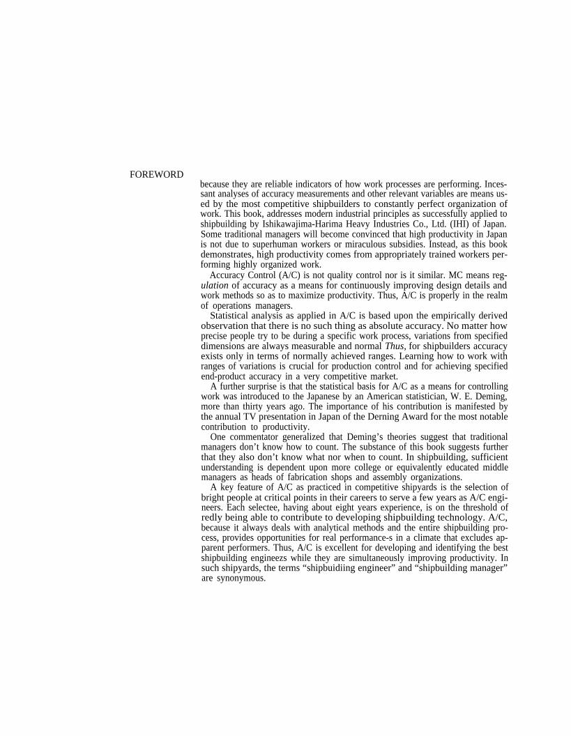
FOREWORDbecause they are reliable indicators of how work processes are performing. Inces-sant analyses of accuracy measurements and other relevant variables are means us-ed by the most competitive shipbuilders to constantly perfect organization ofwork. This book, addresses modern industrial principles as successfully applied toshipbuilding by Ishikawajima-Harima Heavy Industries Co., Ltd. (IHI) of Japan.Some traditional managers will become convinced that high productivity in Japanis not due to superhuman workers or miraculous subsidies. Instead, as this bookdemonstrates, high productivity comes from appropriately trained workers per-forming highly organized work.
Accuracy Control (A/C) is not quality control nor is it similar. MC means reg-ulation of accuracy as a means for continuously improving design details andwork methods so as to maximize productivity. Thus, A/C is properly in the realmof operations managers.
Statistical analysis as applied in A/C is based upon the empirically derivedobservation that there is no such thing as absolute accuracy. No matter howprecise people try to be during a specific work process, variations from specifieddimensions are always measurable and normal Thus, for shipbuilders accuracyexists only in terms of normally achieved ranges. Learning how to work withranges of variations is crucial for production control and for achieving specifiedend-product accuracy in a very competitive market.
A further surprise is that the statistical basis for A/C as a means for controllingwork was introduced to the Japanese by an American statistician, W. E. Deming,more than thirty years ago. The importance of his contribution is manifested bythe annual TV presentation in Japan of the Derning Award for the most notablecontribution to productivity.
One commentator generalized that Deming’s theories suggest that traditionalmanagers don’t know how to count. The substance of this book suggests furtherthat they also don’t know what nor when to count. In shipbuilding, sufficientunderstanding is dependent upon more college or equivalently educated middlemanagers as heads of fabrication shops and assembly organizations.
A key feature of A/C as practiced in competitive shipyards is the selection ofbright people at critical points in their careers to serve a few years as A/C engi-neers. Each selectee, having about eight years experience, is on the threshold ofredly being able to contribute to developing shipbuilding technology. A/C,because it always deals with analytical methods and the entire shipbuilding pro-cess, provides opportunities for real performance-s in a climate that excludes ap-parent performers. Thus, A/C is excellent for developing and identifying the bestshipbuilding engineezs while they are simultaneously improving productivity. Insuch shipyards, the terms “shipbuidiing engineer” and “shipbuilding manager”are synonymous.
FOREWORD (Continued)
Because of shrinkage and deformation, A/C is crucial for competitive hull-construction work. This book is limited accordingly. When A/C is perfected forhull construction, similar techniques can be applied elsewhere.
Unlike other A/C publications, this book speaks of “variation” instead of “er-ror”. Errors are acts that through ignorance, deficiency or accident cause depar-tures from specified dimensions. They do not normally occur. A/C deals withvariations that occur during normal operations.
Further, in this book the word “margin” designates a commitment to rework.“Excess” is used to designate an allowance for accumulated variation that can bepredicted with a high degree of probability. Something with excess is ftish cut andprobably does not require rework. Margins always require rework.
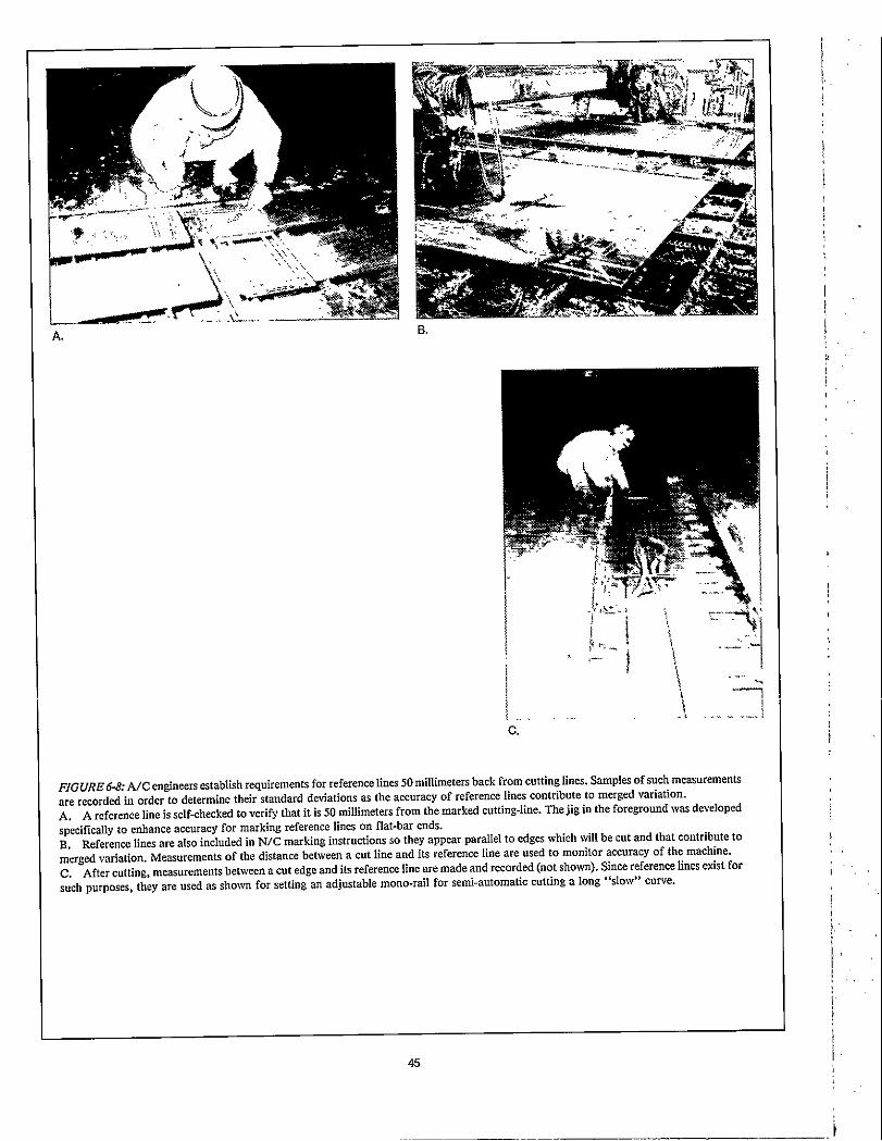
WC is a scientific procedure which is alien to traditional shipbuilders. Becauseof its scientific nature, this book is not for a casual reader. Periodic reference tothe numerous photographs in Part 6.11 will facilitate understanding.
ACKNOWLEDGEMENTS The material on which this book is based was compiled by a project team led byS. Nakanishi, International Division, Ishikawajima-Harima Heavy IndustriesCo., Ltd. (IHI) of Japan. Team members included K. Ando and M. Hatake. Allare truly professional shipbuilding engineers/managers.
The editor and contributing author is L.D. Chirillo who serves Todd PacificShipyards Corporation, Los Angeles Division as a manager of research projects.He was assisted by R.D. Chirillo and R.L. Storch of L.D. Chirillo Associates andthe University of Washington respectively.
Appreciation is expressed for comments received from Avondale Shipyards,Inc. and Bath Iron Works Corporation.
Appreciation is also expressed to Y. Mikami, M. Kuriki and Y. Ichinose, of IHIMarine Technology, who furnished essential support.
This book is an end-product of one of the many projects managed and costshared by Todd for the National Shipbuilding Research Program. The Program isa cooperative effort by the Maritime Administrator’s Office of Advanced ShipDevelopment and the U.S. shipbuilding industry. The objective, described by theShip Production Committee of the Society of Naval Architects and MarineEngineers, is to improve productivity.


Ex SCIENTIA EFFICIENS
*Reprinted by Permission; Copyright © 1981 U.S. Naval Institute
v
---

vi
1.0 INTRODUCTION
1.1. General
Accuracy impacts on productivity. Thus, accuracy is aprime and continuing concern among professional ship-building engineers. They regard Accuracy Control (A/c.),i.e., abilities to regulate accuracy, fust and foremost as amanagement tool for continuously improving productivity.
Statistics is the branch of mathematics dealing with collec-tion, analysis, interpretation and presentation of masses ofnumerical data. The methods of statistics are methods of ap-plied mathematics. Shipbuilding engineers who manage A/Cprograms must at least understand college-level elementarystatistics.
Other prerequisites pertain to the data needed. An A/Cdata base is a major investment. At first it requires systematicrecording of thousands of measurements. Such efforts areexpensive. They will deter traditional managers having short-term goals. These people are more likely to apply what theybelieve to be A/C as sporadic and unsophisticated preventivesteps in response to one particular customer’s requirement fora specific degree of accuracy.
Lack of long-term application negates the central impor-tance of statistically-valid data which describes a shipyard’snormal accuracy performances. Such data is the basis forcontinuing the collection of measurements by mathematicallydetermined sampling and for continued analysis and interpre-tation.
Competitive shipbuilders regard their A/C data base as acapital investment and means of production every bit as indis-pensable as a crane or a building dock. The significant costfor starting an A/C program makes sense only when it isamortized over future projects just as any other large capitalinvestment. Costs for continuing the collection of data as anormal part of a production process, are nominal because ofthe sampling techniques employed.
A/C cannot be effectively applied in the absence of aproduct-oriented work-breakdown structure which featuresinterim products (i.e., fabricated parts and various subassem-blies) classified by the problem areas their manufacture im-poses. This is the singular means used by the world’s mostcompetitive shipbuilders to operate both real and virtualwork-flow lanes for a high variety of objects in mixed quan-tities.’
Because the different interim-products are classified bycommon problem-areas, the same work situations are suffi-ciently repeated within each area for statistical treatment.Moreover, as sets of solutions, e.g., specific classes of workerskills and facilities, are matched to problem areas, A/C datais unaffected by variations that would otherwise occur.
Some product-oriented shipbuilders evaluate each propos-ed interim-product or a lot consisting of more than one, forits efficiency as a work package. Productivity Value (PV) isexpressed by the formula
PV = f(T,N,Q
where:T = time allowed for its accomplishment,N = number of units of resources, andQ = quality of work environment and accuracy speci-
fied for the interim product.
The function (T,N,Q) is determined empirically and separ-ately for each stage within each flow lane. Each necessarilyconsiders the irmnediately preceding and folIowing workstages.
Having PV vary directly with Q insofar as it applies toaccuracy specifiedfor the interim product seems to be a para-dox. However, in this case Q relates to the efficiency of thetolerances specified with subsequent assembly work in mind.Are the tolerances too accurate? Are they accurate enough?A/C provides the method for detemining the optimum toler-ances required at each stage consistent with the needs ofcustomers, regulatory societies and productivity.
When customers vary their accuracy requirements, as fordifferent ships in different services, A/C provides quan-titative means to change details and assembly sequences, andto adjust tolerances to suit. This ability to better control pro-duction through control of accuracy is a tremendous competi-tive edge.
“Product Work Breakdown Structure - November 1980” by Y. Okayana and L.D. Chirillo for the National Shipbuilding Research Program.
1

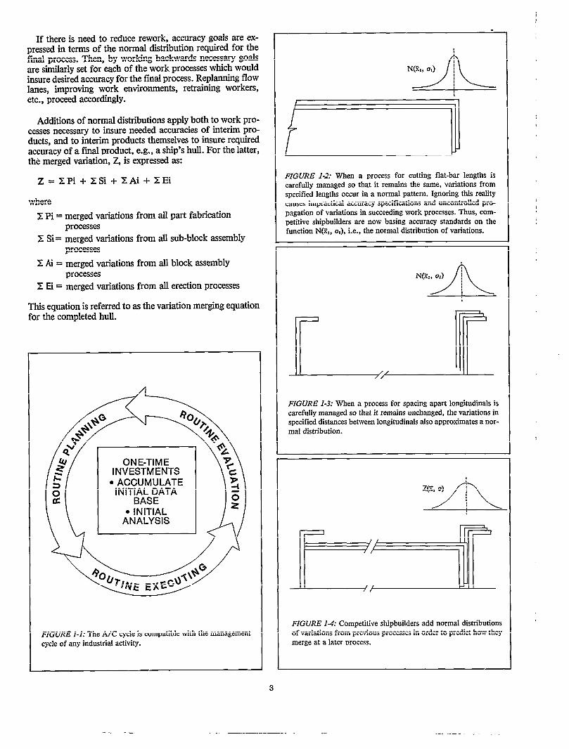
A/C is a repeating cycle of plan, execute, evaluate andrepIan; Figure 1-1. Vital points and dimensions for blocks,sub-blocks and parts that are needed to assure accuracy of anend product are identified. They are systematically monitoredat designated production stages. Similarity, many othermeasurements are made and carefldly documented untilscientifically-valid samples of accuracy data have been col-lected. The data are evaluated using statistical methods toverify performance in terms of standard ranges of accuracynormally encountered and tolerance limits beyond whichrework is required. By including such written requirements inwork instructions and by systematically monitoring, A/C“tightens up” all activities along a production line, e.g.,template production, marking, cutting, bending, fitting,welding, and line heating so that the tolerance requirementsfor each are compatible with the others’. No longer arecrucial judgments about accuracy left to opinions andguesses.
A specific example of “tightening up” for a particularwork process was further development of line heating to moreaccurately form curved hull-parts as a means of minimizingerection work. Man-hours required for bending were reducedto almost one third those needed for conventional rollingor pressing, fewer clips, dogs, wedges, etc. were requiredby assembly workers, and rework for adjusting joint-gapsduring hull erection was greatly reduced.
Where most effectively applied, A/C engineers are as-signed thoughout the operations department. Because theirmethods are analytical and always address the entire ship-building process their recommendations are inherently apoli-tical. Thus, they have the best opportunities for developingthemselves as shipbuilding engineers. As A/C experience isvirtually prerequisite for higher managerial jobs, candidatesare carefully selected from people having about eight yearsshipbuilding experience and memberships are rotated. Thisviable group, in addition to its day-today planning, executingand evaluating, functions as a defacto staff, i.e., advisorygroup, to the operations manager and his deputies.
A/C provides scientifically derived, written and realisticallyobtainable accuracy standards and goals. A/C is a functionthat transcends departmental responsibtities. Whether itshould be adopted should not be left to department or shopmanagers whose concerns are parochial.
A/C reports contain essential and reliable data thatmeasure critical aspects of production performance and in-dicate where improvements are required. Quite apart fromcontrolling accuracy, A/C also defines management optionsregarding all aspects of an operations organization. Implem-entation requires total management commitment. In eachshipyard, A/C should significantly preoccupy the most senioroperations manager.
1..2 Basic Statistical Principles
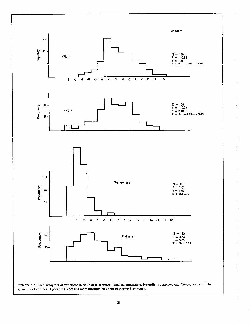
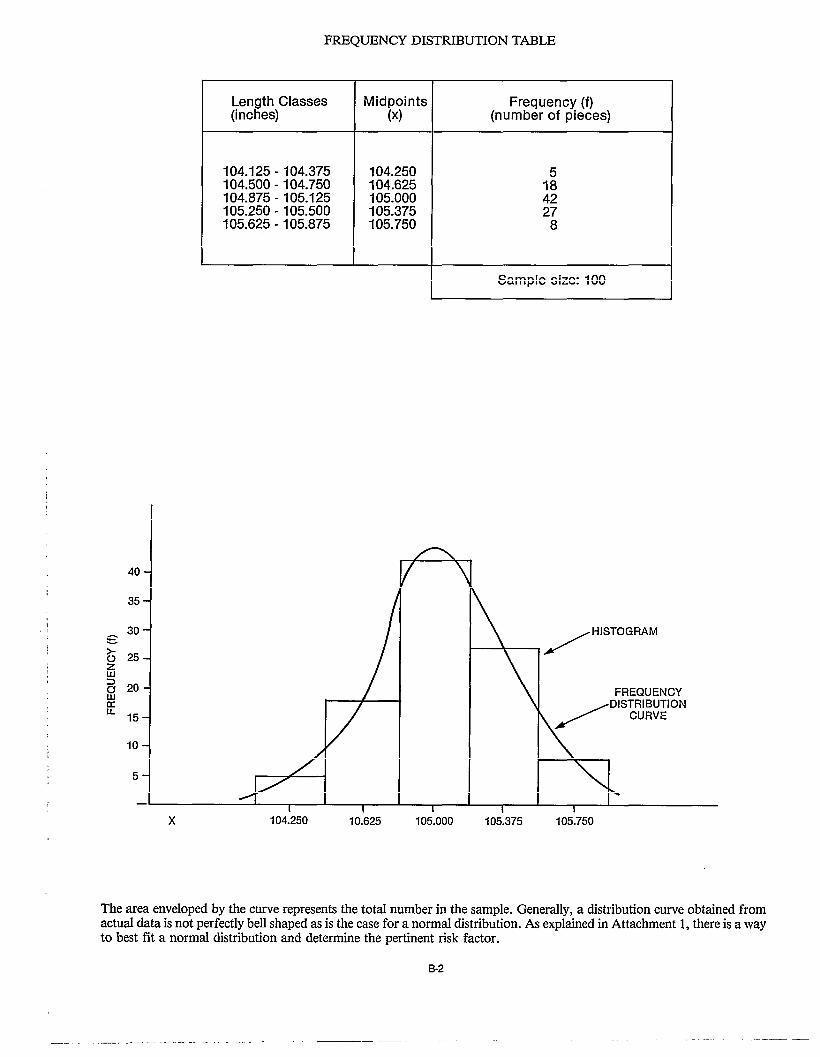
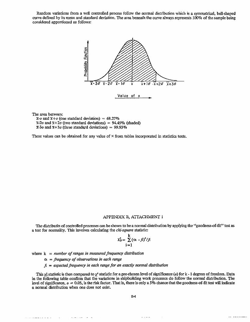
When flat-bar parts are fabricated during work circum-stances that are controlled, e.g., unchanged in facilities andworker skills, part lengths vary. Variations of specific magni-tudes when plotted by the number of times they occurapproximate a normal dktribution; see Figure 1-2. Twouseful characteristics which describe the relative shape of anormal distribution (N) are:
tions in a sample, and
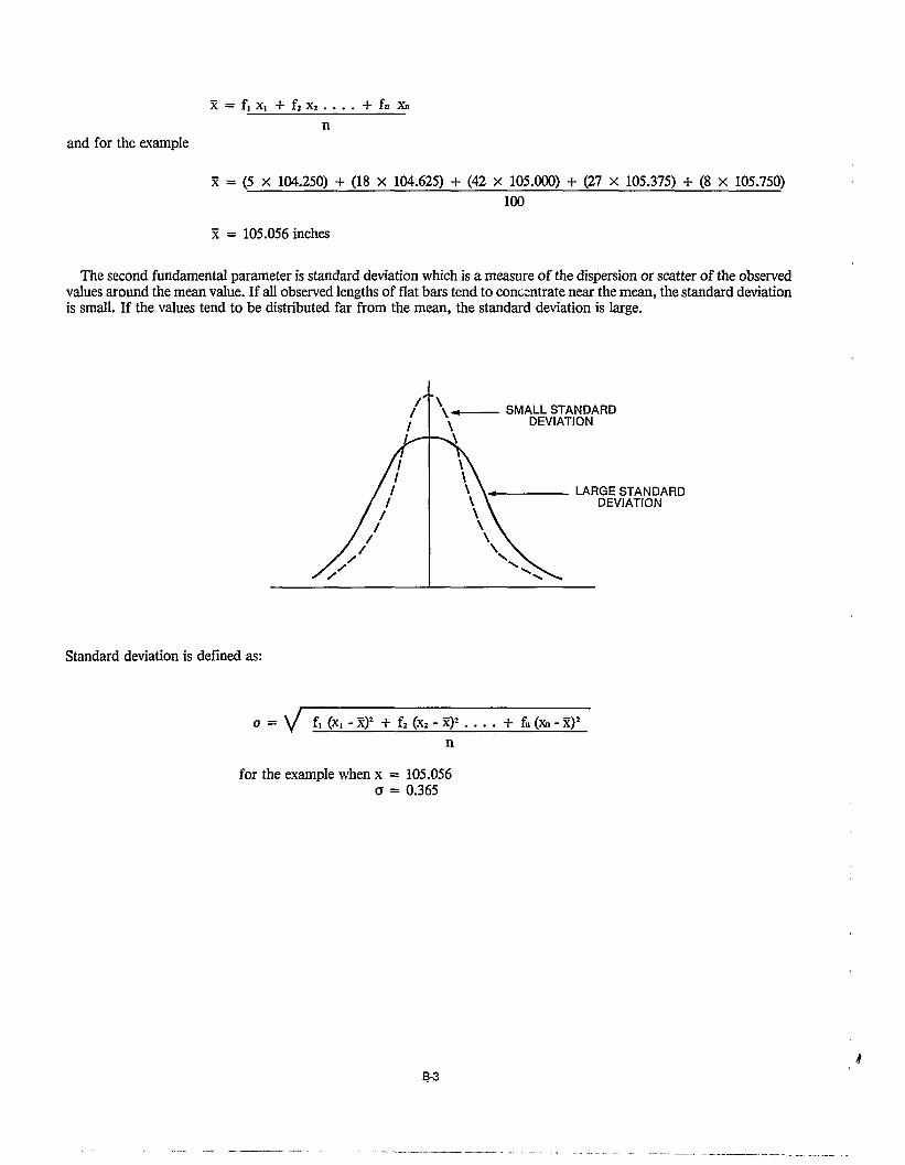
.l its standard deviation, o, which classes the sizes of var-iations from the mean value by their frequencies of oc-curance, e.g., 68% within a specific variation size,95% within a larger size and so on.
Both characteristics are obtainable from mathematical for-mulas.
Sinilarly, spacings between Iongitudinals vary and anothernormal distribution having its own mean value and standarddeviation applies; see Figure 1-3. Whether the variations inboth flat-bar lengths and longitudinal spacings impose pros-pects for rework, depends upon their merger during a laterassembly process.
Statistics provides a theorem for addition of two normaldistributions which is used to obtain the normal distributionfor fitting cut flat-bars between Iongitudinals; see Figure 1-4.Thus, a mean value and standard deviation can also be ex-pressed for this latter assembly process. Further, the workprocess which contributed most to the final or merged varia-tion is identified.

2.0 APPROACH
Ships are built by procuring or fabricating parts and thenjoining them to create subassemblies. In turn, these are com-bined through several manufacturing levels to produce in-creasingly larger subassemblies and ultimately a completeship. Competitive shipbuilders apply production-line techni-ques for the many different interim products required.
A production line is sequentially arranged work processes;it is a preplanned entity. Efficiency is dependent uponuniform work flow and coordination with other productionlines. Optimum accuracy is crucial in order to avoid disrup-tive rework. Even nominal rework can break down the eco-nomic advantages of a production line. Thus, when thinkingabout how a ship is to be assembled, planners must addresstheir shipyard’s accuracy capabfities. A shipbuilder who hasto compete, must support MC planners with good systemsfor collecting and evaluating accuracy data.
In the absence of such measures the following typical ques-tions are disregarded:
What dimensions are vitally important to achieve re-quired accuracy?
How is the required degree of accuracy going to beachieved?
In what work processes should vital dimensions be con-trolled?
What are the tolerances that should be imposed at eachwork process?
Without tolerances specified for each process there is no wayto control the accumulation of variations at a final process.
Tolerances in shipbuilding can be classified in two groups:
l end-product tolerances - some are fixed as by classifica-tion societies, and others which are invoked by ownerscan be negotiated, and
l interim-product tolerances - these are applied by a ship-yard to insure compliance with end-product tolerancesand simultaneously to maximize productivity (tolerancesfor productivity reasons are often more demanding thanthose imposed by classification societies and owners).
As a ship owner’s guide to what can be achieved at reason-able costs for hull structure, Japanese shipbuilders, classifica-tion societies and universities colkctively produced tableswhich:
apply to many details, parts and subassemblies,
shipyards,
. provide standard ranges of actual dimensions achievedwhich by deftition reflect 95% probabfity for normalshipyard practice,
and
tinuing improvements in shipbuilding technology.*
Ship owners have to pay more if they specify closer tolerancesthan those normally achieved as described in the foregoing.
1 “Japanese Shipbuilding Quality Standard (Hull Part) -1979” by the Research committee on Steel Shipbuilding, the Society of Naval Architectsof Japan. Per this document, 99.7% of the contributing shipyrtrds’ data is within tolerance limits, i.e., normally only 0.3% of the situations ad-dressed in the Standard require rework.
5

3.0 PLANNING
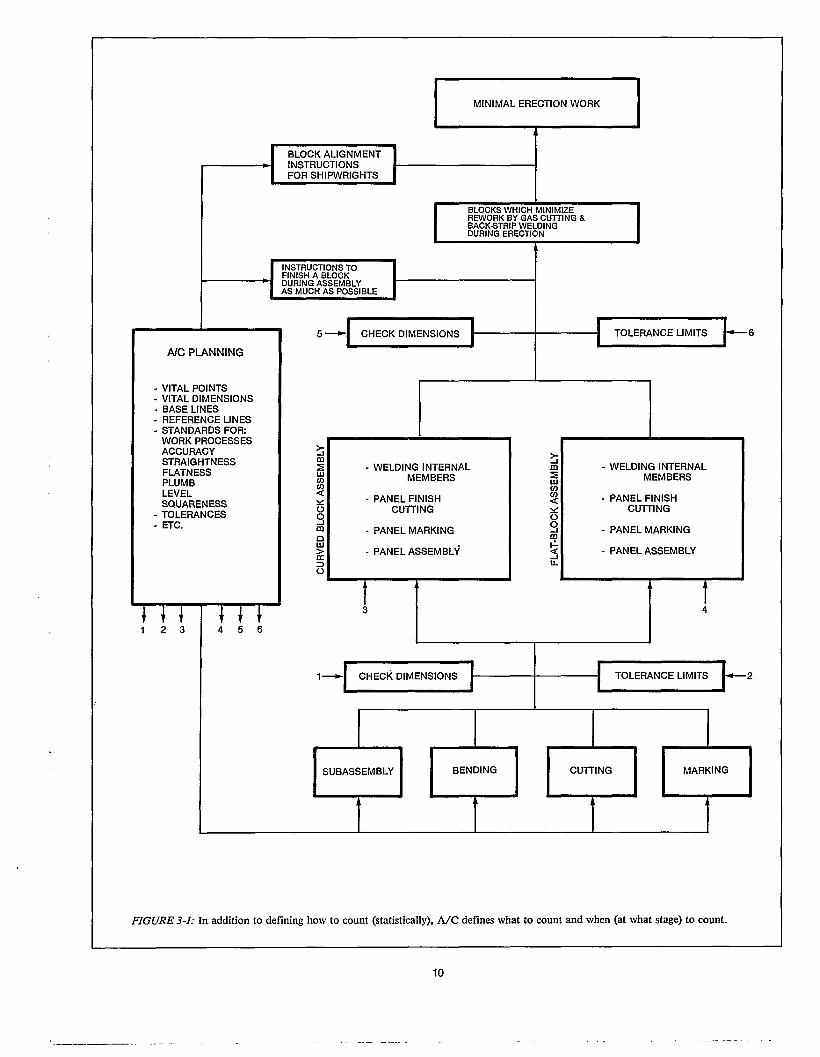
Figure 3-1 shows when A/C activities are applied duringearlier work stages in order to minimize rework at the erec-tion stage. Basically, what is shown is the role of A/C plan-ning to:
. pinpoint what vital points and dimensions are critical tothe dimensional and geometrical accuracy of blocks,
designate critical check points and reference lines inblocks and in the sub-blocks and parts from whichblocks are assembled,
specify locations for and amounts of excess allowances,
decide where and how much margin is to be used and thespecific stages at which margins shouId be cut neat,
determine work processes during which check measure-ments will be made,
fix the numbers of interim products that should bemeasured based upon random sampling, and
incorporate tolerance limits, excess allowances and mar-gins in work instructions.
A/C planning is best performed together with other plan-ning elements provided it receives at least the same emphasis.For effectiveness, specific A/C responsibilities should beclearly defined and specifically assigned to individuals. Aspreviously shown in Figure 2-3, A/C planning can be dividedas other major planning aspects into:
3.1 Priliminary Planning
Preliminary planning addresses such matters as block divi-sions, hull straking, and assembly procedures. Necessarily,preliminary planners must consider among other things:
how to create blocks that facilitate shipwright work,
how to strake the hull shell in order to design hull platesthat can be accurately formed by available bending facilities and techniques, and
how to shape blocks that are spacious and open to facili-tate zone outfitting.
In order to carry out such studies systematically, drawingssuch as a general arrangement, midship section and lines andproposed schemes for block divisions and shell straking, areprovided by designers to the planners who are assigned at thehulkonstruction department level and to the parts-fabrica-tion shop, sub-block assembly section, block assembly sectionand erection section. As a routine matter the same informa-tion is equally available to the specific engineers among theplanners who have been assigned A/C responsibilities.. Theyapply analytical techniques based upon statistically obtainedassessments of normal accuracy performances and proposeoptimum design details, assembly and erection sequences, tol-erances etc., accordingly. The final scheme is fed back todesigners who then develop key plans, such as a shell expan-sion, a block plan and ultimately work instructions all ofwhich contain A/C derived requirements.
3.2 Detail Planning
A/C considerations in detail planning are really processanalyses from an A/C viewpoint. Through such analyses pro-blems which can be solved by regulating certain dimensions,are revealed in advance. In other words, in order to obtainrequired accuracy for a final process it is necessary to firstidentify the specific preceding processes that are mostly con-tributing to a final or merged variation. Thus A/C analysesidentify on a quantitative basis, both the work processes anddesign details which should be improved.
9
Of course, such determinations are not made solely froman A/C viewpoint. A/C techniques are analytical manage-ment tools that contribute to process analyses. They aremeans for a shipyard as an entity to capture and scientificallyderive benefits from its accuracy experiences. The alternativeis to have such experiences just vested in individuals who candemonstrate some pertinent, parochial expertise, but who canonly guess about how their accuracy achievements impact onother work processes. A/C methods in detail planning are sig-nificant because they inherently address the entire hull con-struction process for the purpose of reducing erection work.
Planning proceeds by first assessing the accuracy character-istics for an end-product as specified by a regulatory societyand ship-owner. Thinking of reverse process flow, A/C plan-ners identify vital points and dimensions that must be main-tained during erection, block assembly and so on as furtherdescribed in Appendix A. In consideration of such vitalaspects A/C planners insure that via work instructions andother means, Ioftsmen and people having A/C field respon-sibilities, are provided with necessary information such ascheck points and reference lines that must be included innumerical control (N/C) data, templates and field check-sheets.
Engineers who perform A/C planning for construction ofa ship, recognize that most accuracy variations in work pro-cesses are normal and their impact on an end product can bepredicted through statistical methods. The statistical termino-logy, notations and formulas included in the followingpassages, are further explained in Appendix B.
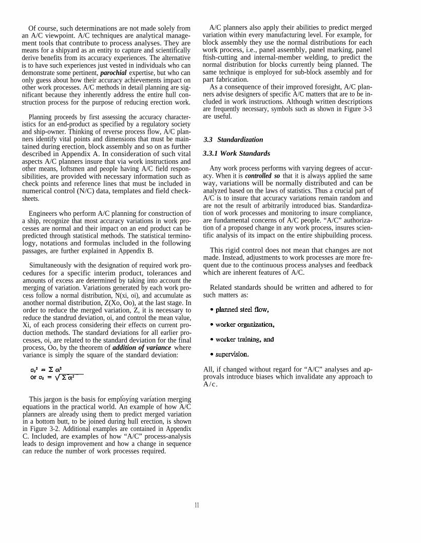
Simultaneously with the designation of required work pro-cedures for a specific interim product, tolerances andamounts of excess are determined by taking into account themerging of variation. Variations generated by each work pro-cess follow a normal distribution, N(xi, oi), and accumulate asanother normal distribution, Z(Xo, Oo), at the last stage. Inorder to reduce the merged variation, Z, it is necessary toreduce the standrud deviation, oi, and control the mean value,Xi, of each process considering their effects on current pro-duction methods. The standard deviations for all earlier pro-cesses, oi, are related to the standard deviation for the finalprocess, Oo, by the theorem of addition of variance wherevariance is simply the square of the standard deviation:
A/C planners also apply their abilities to predict mergedvariation within every manufacturing level. For example, forblock assembly they use the normal distributions for eachwork process, i.e., panel assembly, panel marking, panelftish-cutting and internal-member welding, to predict thenormal distribution for blocks currently being planned. Thesame technique is employed for sub-block assembly and forpart fabrication.
As a consequence of their improved foresight, A/C plan-ners advise designers of specific A/C matters that are to be in-cluded in work instructions. Although written descriptionsare frequently necessary, symbols such as shown in Figure 3-3are useful.
3.3 Standardization
3.3.1 Work Standards
Any work process performs with varying degrees of accur-acy. When it is controlled so that it is always applied the sameway, variations will be normally distributed and can beanalyzed based on the laws of statistics. Thus a crucial part ofA/C is to insure that accuracy variations remain random andare not the result of arbitrarily introduced bias. Standardiza-tion of work processes and monitoring to insure compliance,are fundamental concerns of A/C people. “A/C” authoriza-tion of a proposed change in any work process, insures scien-tific analysis of its impact on the entire shipbuilding process.
This rigid control does not mean that changes are notmade. Instead, adjustments to work processes are more fre-quent due to the continuous process analyses and feedbackwhich are inherent features of A/C.
Related standards shouId be written and adhered to forsuch matters as:
All, if changed without regard for “A/C” analyses and ap-provals introduce biases which invalidate any approach toA/c.
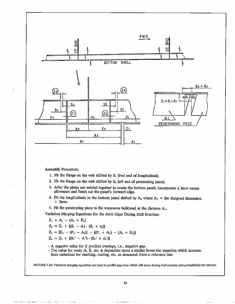
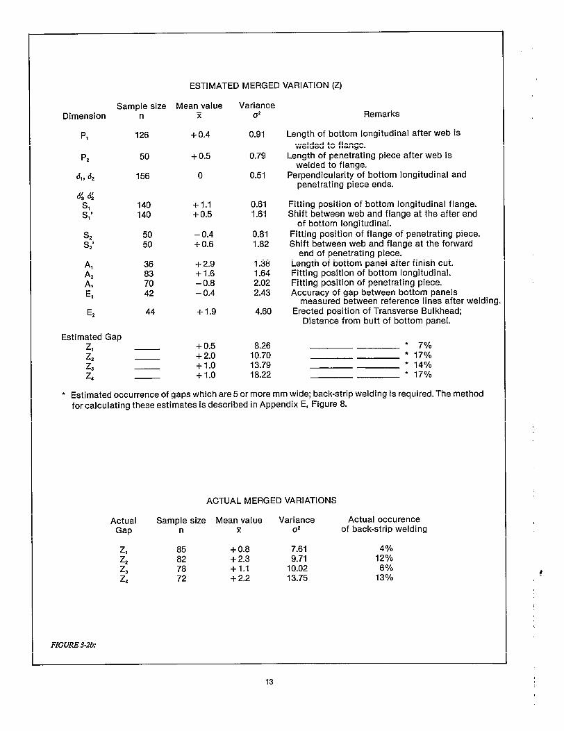
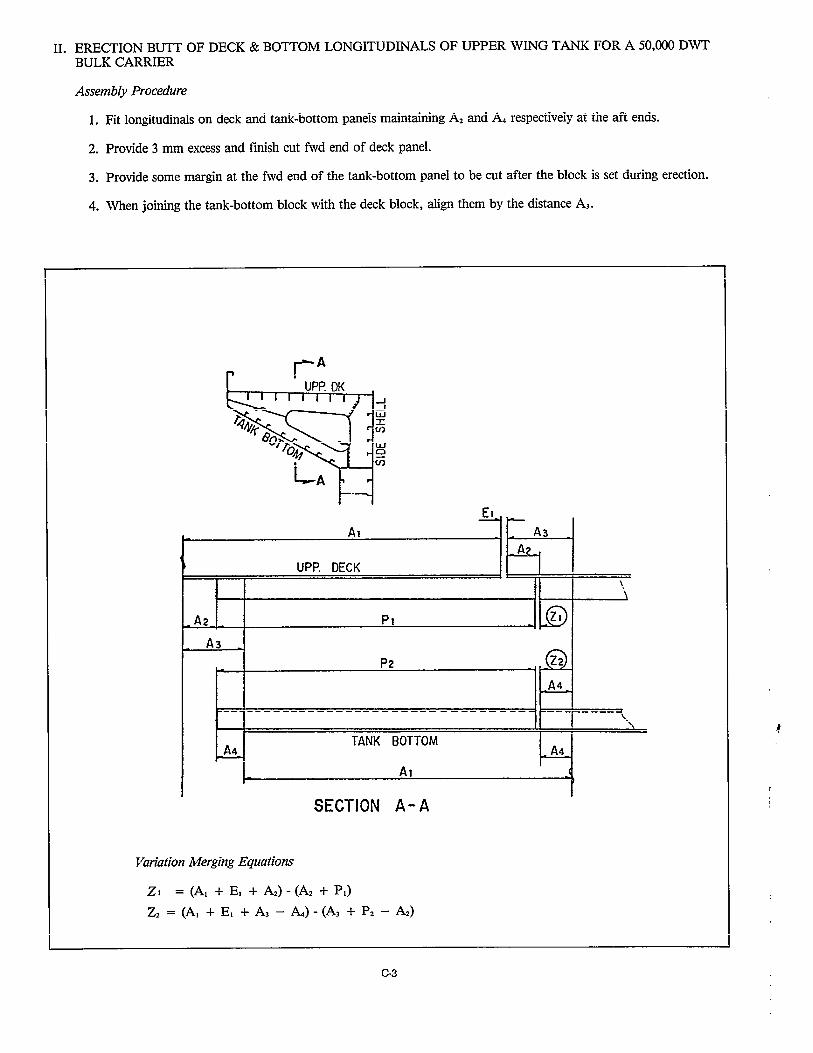
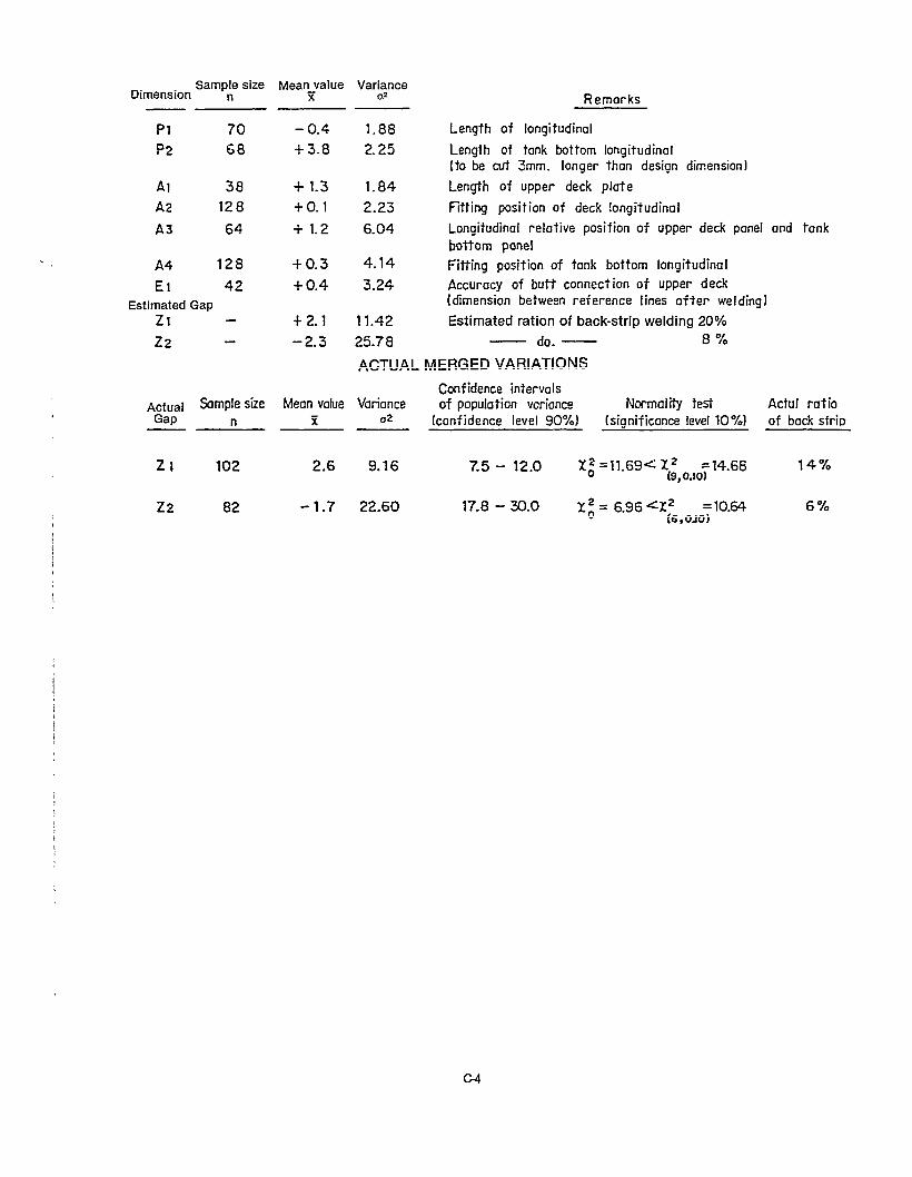
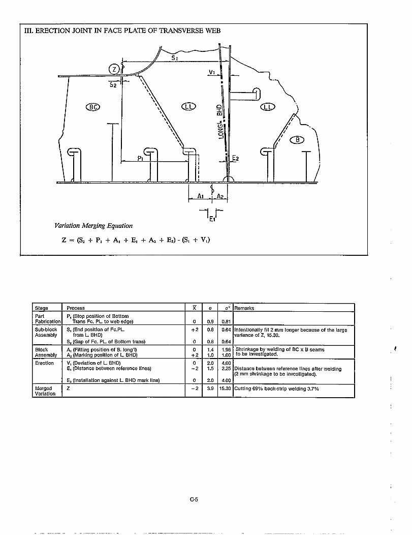
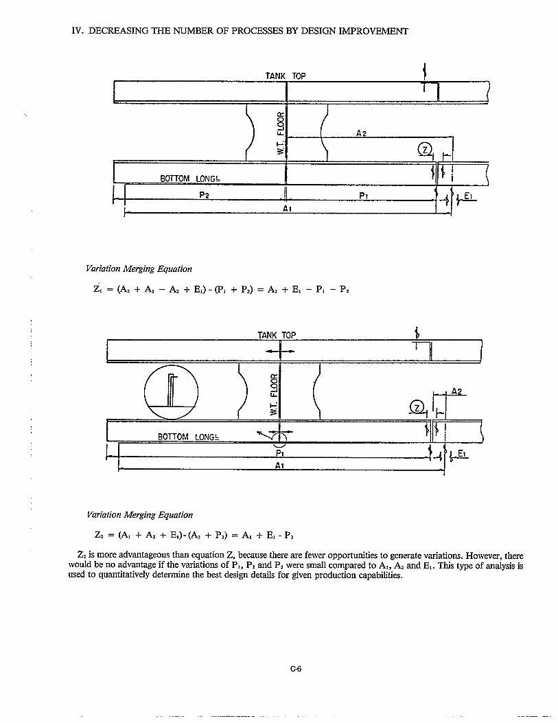
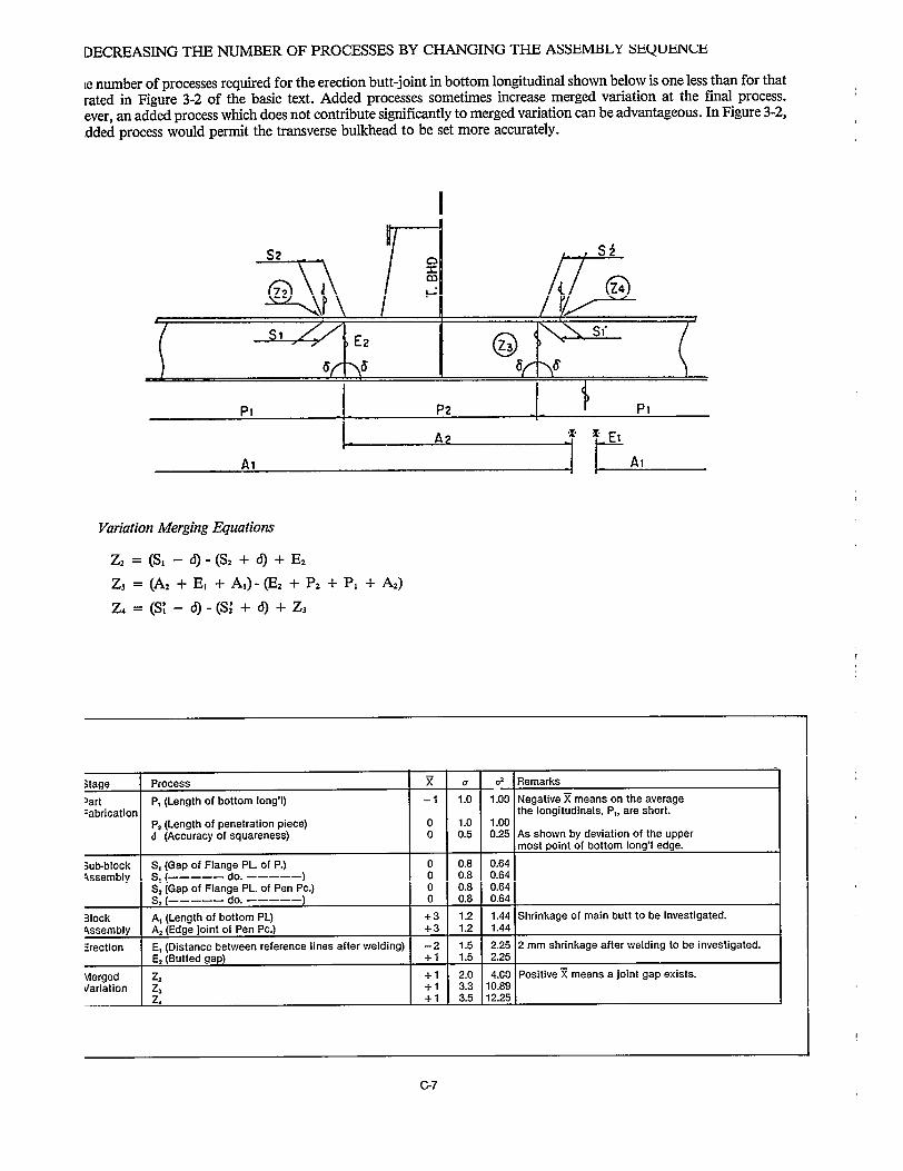
This jargon is the basis for employing variation mergingequations in the practical world. An example of how A/Cplanners are already using them to predict merged variationin a bottom butt, to be joined during hull erection, is shownin Figure 3-2. Additional examples are contained in AppendixC. Included, are examples of how “A/C” process-analysisleads to design improvement and how a change in sequencecan reduce the number of work processes required.
11

l Standards for Baselines and Match Marks
Even where the necessity and importance of baselinesand match marks are recognized, their locations andlengths do not sufficiently reflect the production requiire-ments that should be described in a standard.
l Standards for Checking Procedures
A written checking procedure assures specified accuracyat each work process. Because no written checking pro-cedures exist, few measurements are recorded foranalysis.
. Standards for Fabrication and Assembly Schemes
The sequences for sub-block assembly and block assem-bly are usually indicated by a numbering system, usefuIfor computer processing, which is hierarchical in order tomatch ascending manufacturing levels. This system isgood enough to indicate a simple sequence such as partfabrication, sub-block assembly, block assembly anderection, but it does not address vital points and dimen-sions needed to achieve specified accuracy during eachwork process.
l Standards for A/C Information in Work Instructions
Usual hull-construction drawings show structural detailsand sometimes include instructions for edge pre-parations. Specific excess allowances are generally notincluded. Little other guidance is provided by designersto indicate fabrication methods and vital points anddimensions needed to achieve a specified degree ofaccuracy.
Working drawings are the only widely distributed doc-uments provided to workers which can display totalinstructions for how to construct a ship’s hull. Whendesign is recognized as an aspect of planning, workingdrawings will develop more as work instructions whichfacilitate employment of less-skilled workers, adherenceto work standards, A/C analyses and continuousimprovement in production methods.
3.3.2 Accuracy Standards
In order to control the accumulation of variations ormerged variation at a final stage, accuracy standards areestablished for preceding work processes. Data obtained dur-ing construction of other ships is used to derive accuracy stan-dards for a contemplated ship. However, these are reviewedby analyzing data recorded as production commences andprogresses. Adjustments are made if assumed accuracy stan-dards are manifestly unrealistic.
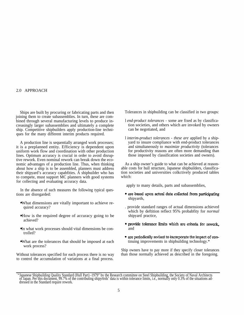
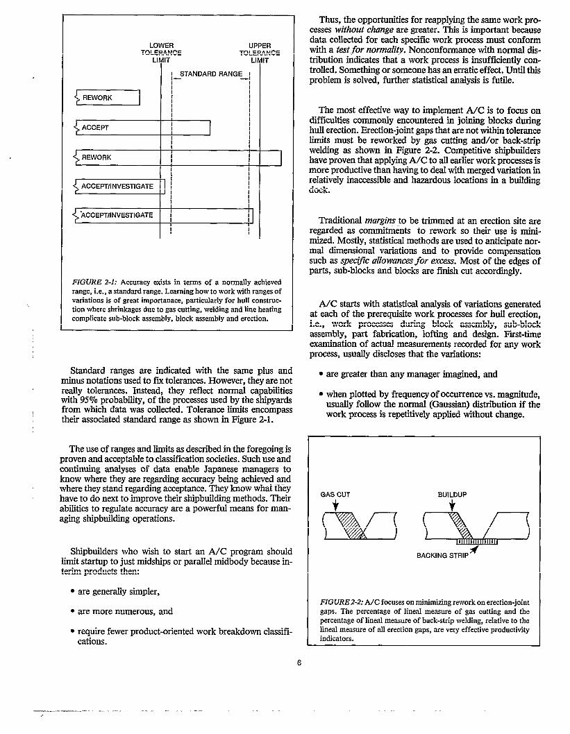
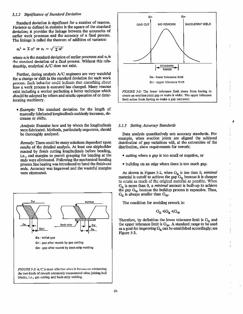
The concept of a standard range with a tolerance limit, asshown in Figure 2-1, is applied to every work process. Themore demanding standard range is used as the accuracy stan-dard for each particular work process in order to insure con-trol of the merged variation at erection. By definition, stan-dard range is associated with high probability (X ± 20 or 95%for shipyards in Japan).
Of the few remaining variations, those outside the standardrange which do not require rework during the next work stagenor spoil end-product accuracy, are acceptable and areregarded as being within a tolerance limit. In other words, atolerance limit because it applies to fewer cases includes someadded allowance for acceptance. However, such limits mustbe achievable with normal production capabilities and mustnot impair structural integrity of the end product.
This approach recognizes basic realities in any industrialenterprise. While more demanding accuracy standards areapplied to normal operations, some allowance is made for theeffect on accuracy by on-the-job trainees, newly developedmachines, etc. The concept of a standard range with a toler-ance limit encourages managers to react to trends away fromnormally achieved accuracy before rework is required.
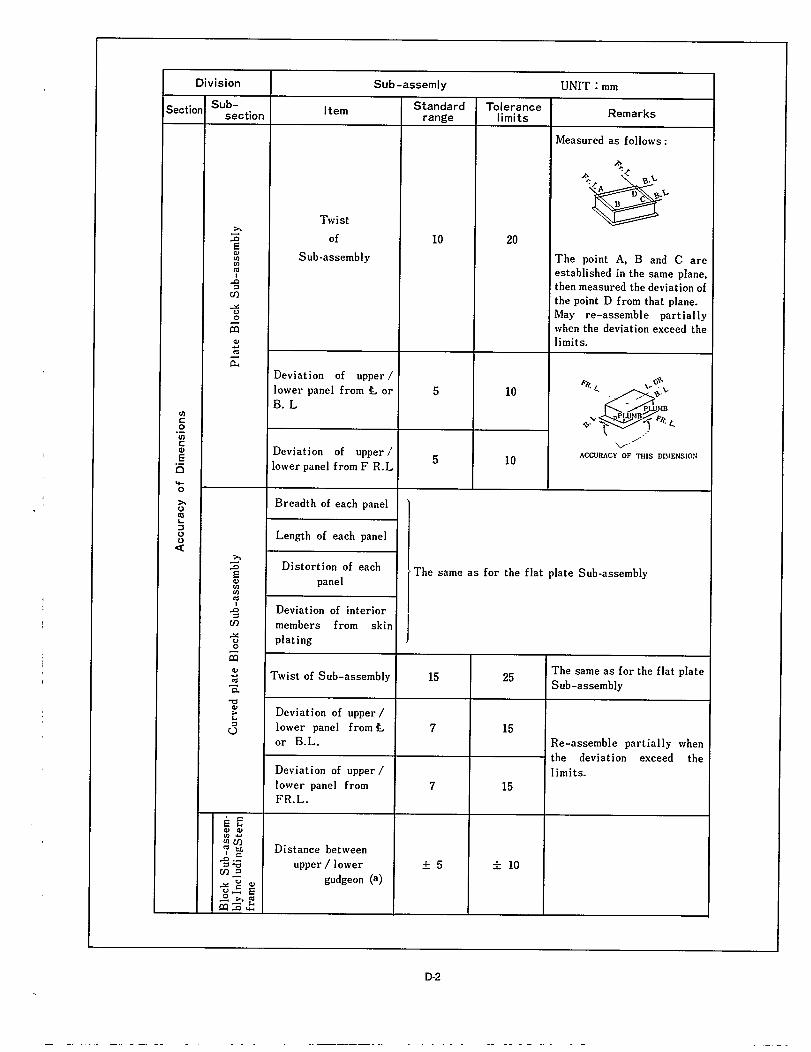
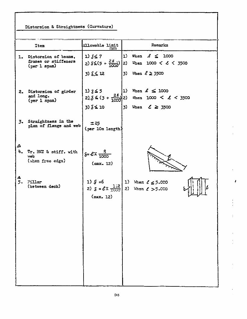
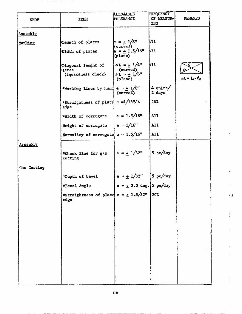
Typical standard ranges and tolerance limits that areemployed for standardization by Japanese shipbuilders aretabulated in Appendix D. These standards, because they havebeen revised five times in thirteen years, reflect constant“A/C” scanning of work processes which foreed industry-wide advances in shipbuilding technology. The constantupgrading is a measure of competition between national ship-building industries.
Some shipbuilders further developed the accuracy stan-dards to address more design details and to further “tighten”work processes as a means for competing with each other.Pertinent samples are also included in Appendix D. The ex-tent of this independent, fhrther development of accuracystandards is a measure of competition between shipyards.
15

4.0 EXECUTING
4.1 Self Check
A/C includes a self-check system which workers and theirimmediate leaders execute. Self checks are crucial. Workershave not completed a job until they have checked their workto assure compliance with written accuracy instructions.Thus, self checks are regarded as work just as much as anyother work task. Subsequently, work leaders, one for approx-imately every eight workers, check the same work and recordthe pertinent final data accordingly. Very important checkpoints and lines, i.e., control items, are again checked andrecorded by the next higher level of supervision. If such datais unreliable or not available there is no point in having A/C.
4.2 A/C Group
Where A/C is successfully applied, people having responsi-bilities to execute A/C procedures are assigned in the hullconstruction department. All are members of a yard-wideA/C group, have 8 to 9 years of varied shipbuilding exper-iences and were carefully selected on the basis of their aptitudefor and commitment to improving productivity. Theirresponsibilities are:
be just dependent on the self-check system.
senior operations manager and attended by the managersand deputies of the major divisions of the operationsdepartment, for discussion of productivity matters.
As participation in A/C provides an excellent overview ofplanning, executing and evaluating, A/C group experience isprerequisite for higher managerial responsibtities. And,because increased productivity is dependent on moremanagers acquiring a complete overview of the entire ship-building process, memberships in an A/C group are rotated.
4.3 When and and to Check
Usually, schedules are posted for starting and finishingdates at each control station for part fabrication, sub-blockassembly and block assembly. Summary sheets for futurework loads are also posted. Self checks, subsequent checksand recordings are regarded as work processes that must
adhere to these schedules. A blackboard in each division ofproduction shows the day-today status.
Normally, the master schedule for block erection, weeklyprogress sheets and a schedule for erection checks based onthe master schedule are posted in an erection office. The day-today status of block erection is maintained on a black-board.
Accuracy checks are performed daily in accordance withschedules that are revised weekly, if necessary. Basically, theitems checked for conformance with accuracy standards are:
excess allowances and marks required for fabrication,assembly and checking work,
shapes, edge preparations, deformation, and the cur-vature of bent parts,
parts or sub-blocks, their fit, gaps for welding, distortionand overall dimensions, and
hull alignment.
4.4 Information for Check Sheets
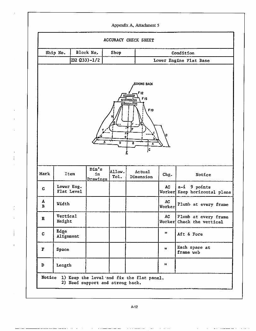
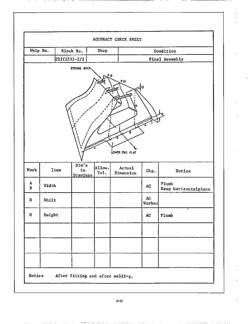
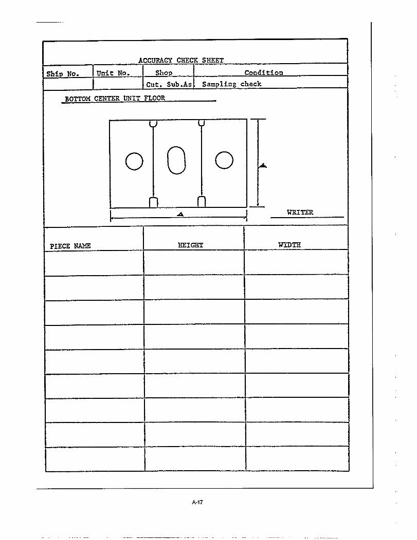
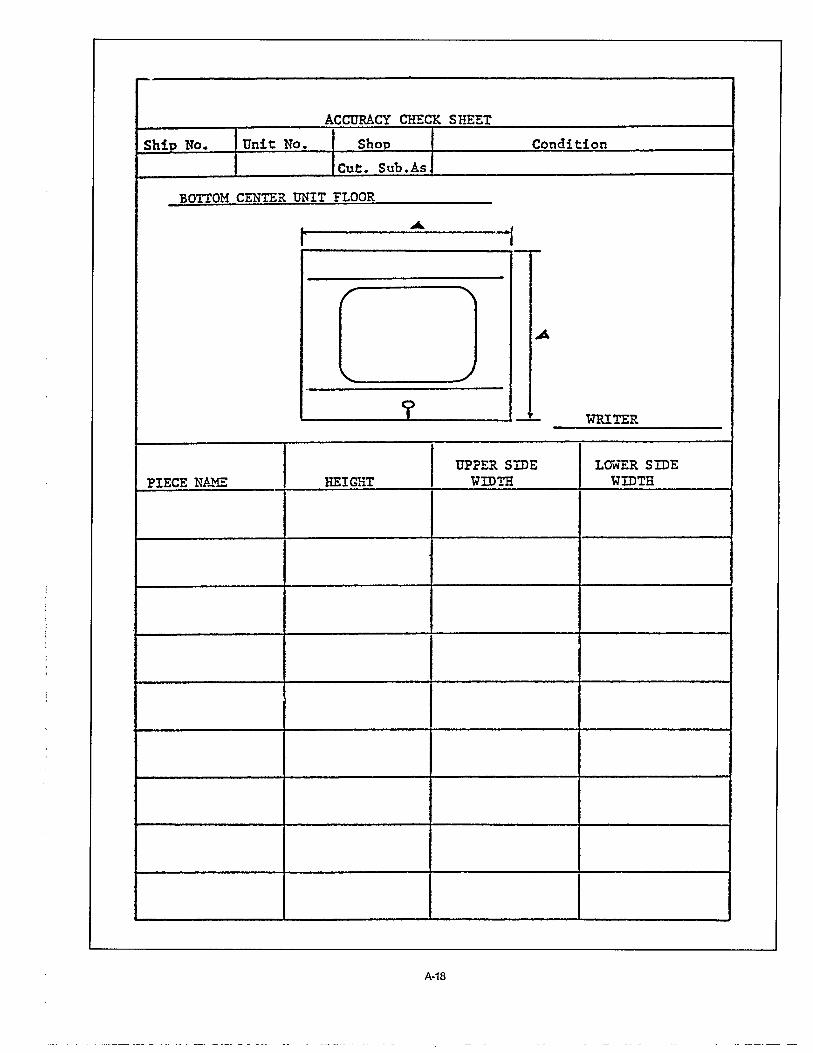
In accordance with work instructions issued by designersand based on information provided by A/C planners, mem-bers of an A/C group in a hull-construction department pre-pare check sheets. These designate check points and lines,checking methods, responsible personnel for measuring, andrequired frequency for measuring. Typical examples of checksheets are incorporated in Appendix A.
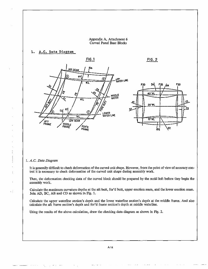
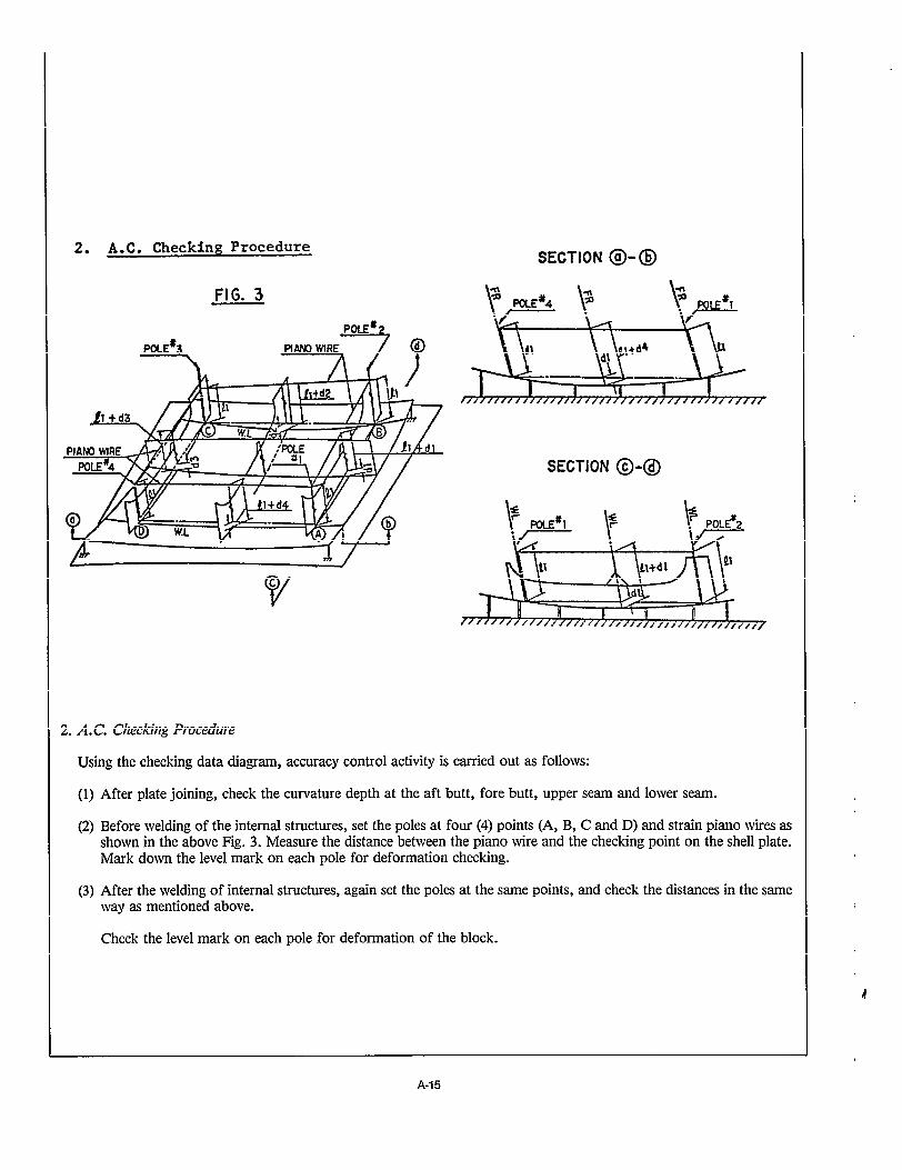
Preparing check sheets for curved blocks is usually difficultbecause the dimensions included in normal working draw-ings, while sufficient for assembly work, are not suitable forchecking purposes. The simplest example are the twodiagonals required for verifying the rectangularity of a panel.The A/C group advises Ioftsmen to calculate numerous otherspecial dimensions that facilitate accuracy checks; examplesof these are also shown in Attachments 4, 5 and 6 of Appen-dix A.
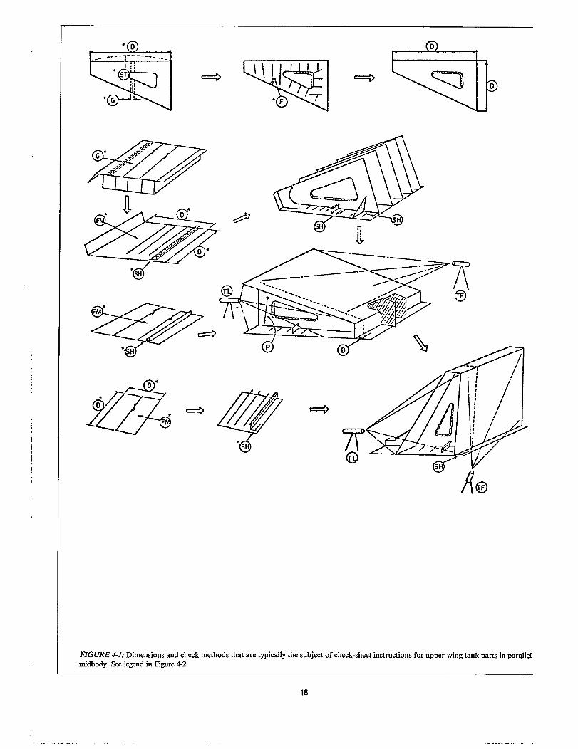
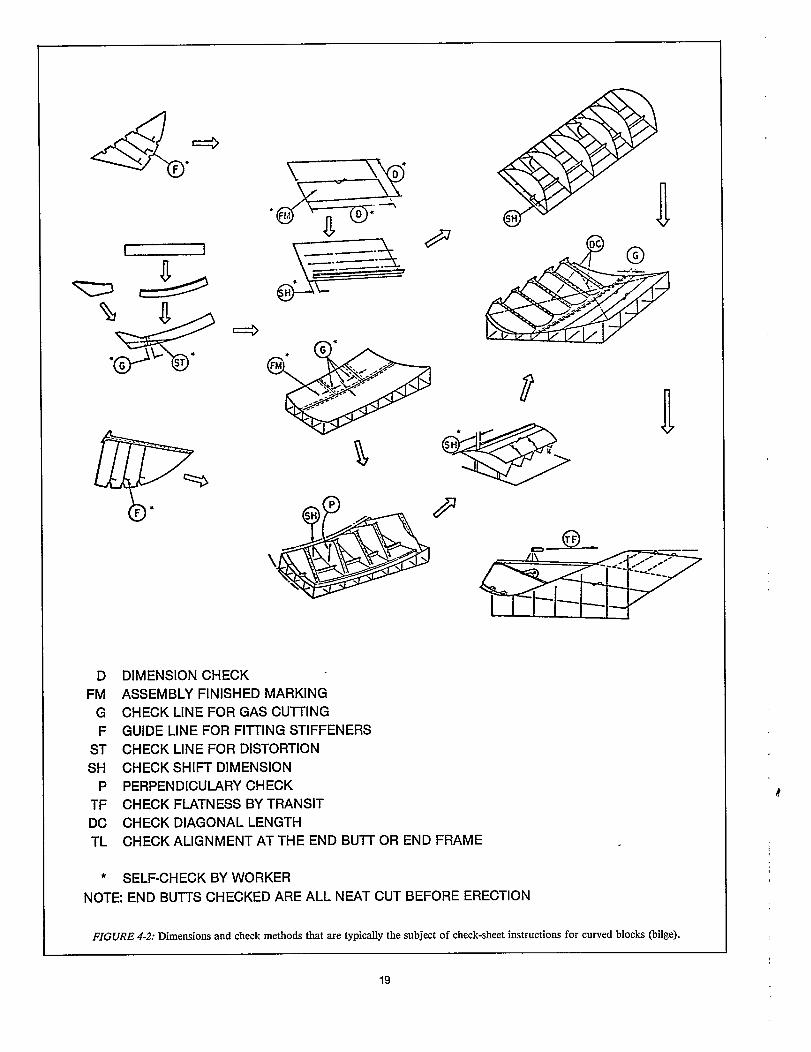
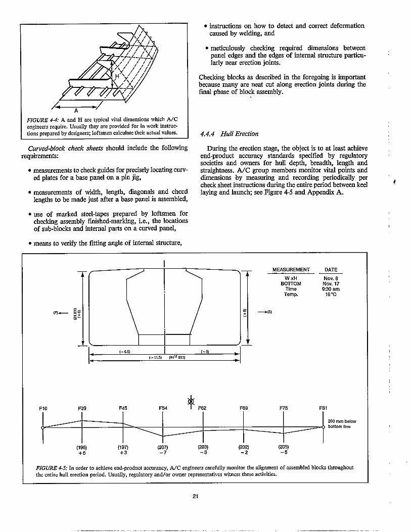
Actual measurements are mainly performed as specified bythe check sheets. However, check sheets cannot practicallyprovide for all dimensions for all hull parts and assemblies.There has to be some dependence on supplementary routinechecking of other dimensions by workers. This helps insurethat the dimensions required by check sheets will satisfyaccuracy standards. Typically, check sheets address dimen-sions and measuring methods as briefly illustrated in Figures4-1 and 4-2.
17


5.0 EVALUATING
Systematized A/C analysis and feedback ensures thatexperiences and lessons learned are acquired by the organiza-tion and translated into improved productivity. As work pro-gresses, all results from check sheets and reported accuracyproblems are analyzed by the WC group before they are sentto concerned organizational divisions. The evaluationsinclude:
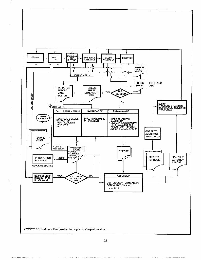
formed on either a regular or an urgent basis.
5.1 Regular analysis
If an analysis discloses an apparent area for improvementan A/C engineer pursues one or more typical options asfollows:
. more detailed investigation of the data,
investigation of instruments used for measuring,
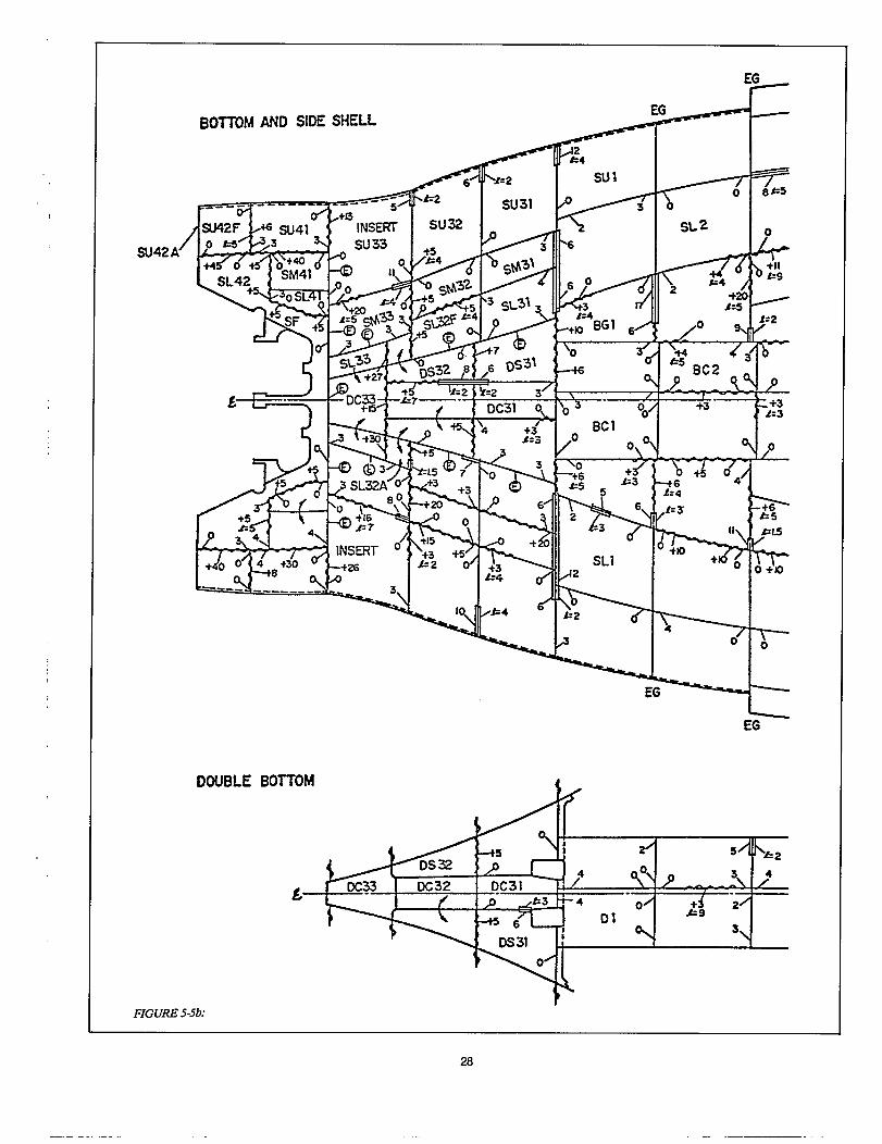
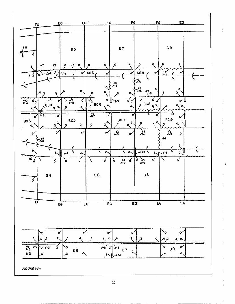
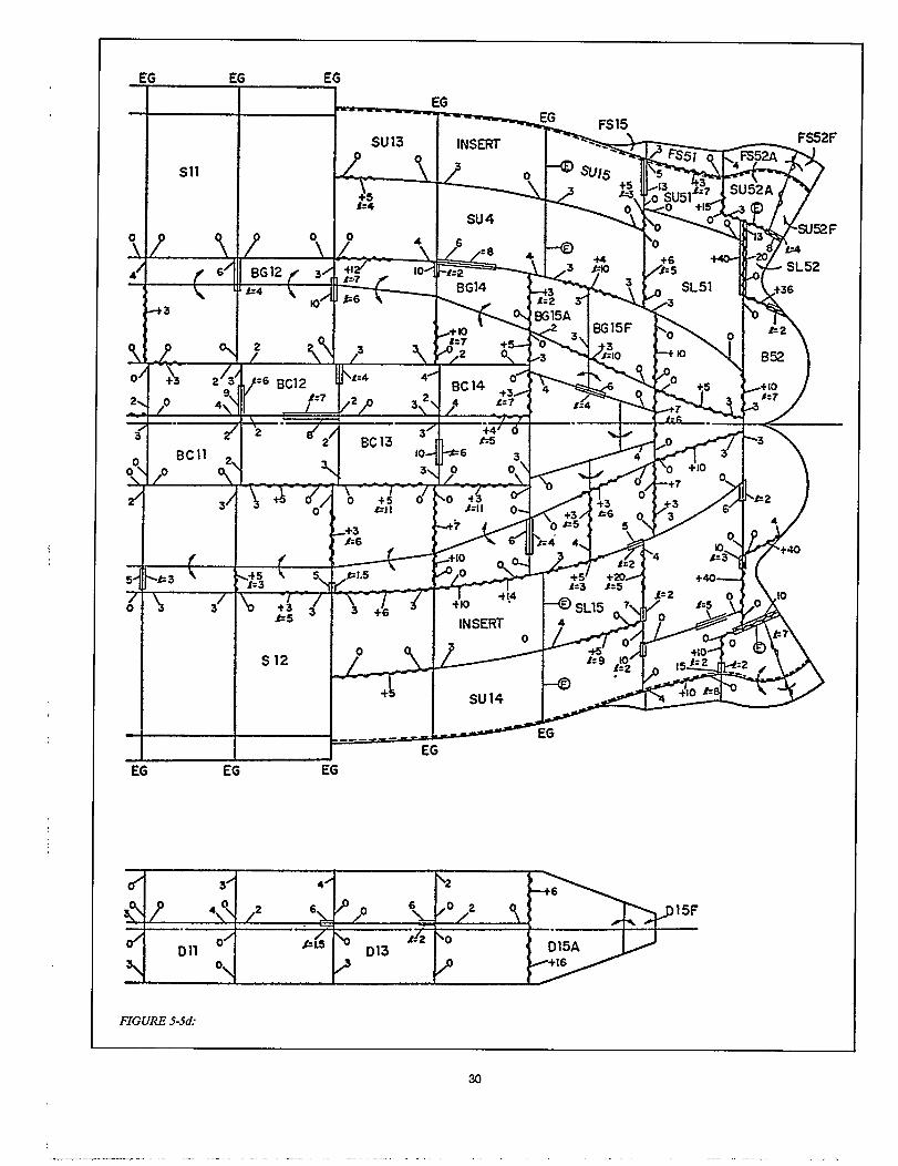
flat-block assembly and cribbing for erection,
Workers perform self checks daily to insure compliancewith accuracy standards. These are again checked and re-corded by their work leaders. Properly collected data, even ifall measurements are within accuracy standards, are used toidentify the characteristics and tendencies of variations. Suchknowledge leads to further improvement in production pro-cesses. An example of data collection and analysis for deter-mining excess allowances is included in Appendix E.
Feedback of analyzed A/C data is vital because it encour-ages planners to review matters such as:
. whether schemes for amounts of excess, vital points anddimensions, etc. were satisfactory,
mum,
. whether work-process standards were suitable, and
. whether sufficient work instructions were provided.
5.1.1 Significance of Mean Value
Generally, a mean value is significant only when associateddata is obtained by random sampling. Data gathered from asmall sample may not be a valid representation of the workprocess being analyzed. For most work processes, the meanvalue for variations is planned to be zero. If the actual meanvalue differs from zero, it should be changed to match resultsof the work processor the work process should be changed soas to yield the planned mean value (zero). The followingexamples apply:
. Example I: Consider a particular dimension for panels,such as for a longitudinal bulkhead under a tank top,which were cut with some allowance for shrinkage. Afterwelding during sub-assembly work, the mean value ofthe dimension was determined to be negative, i.e., someshortage exists compared to the planned zero value.
Analysis: Check kerf compensation if sufficient, theallowance for shrinkage was too small.
Remedy: Add the absolute mean value to the previouslyplanned allowance for shrinkage.
Example 2: Near the end of flat-block assembly, check-ing discloses that plates in tank-top panels are deformedat their centers with a mean value of ½ inch.
Analysis: Check the level of the platen on which the flatblocks were assembled.
Remedy: If the platen is true, improve the assembly workprocesses, e.g., apply pre-tensioning or change weld se-quences.
23


6.0 SUGGESTIONS
6.1 Design
The hull-block construction method developed naturallyfollowing the introduction of welding many years ago. Someshipbuilders changed their organization of structural draw-ings to suit. Appropriate drawing titles evolved such as: blockerection plan, block assembly plan, sub-block assembly planand part-cutting plan. These are more than traditional detail-design drawings because they associate classifications of partsand assemblies with specific manufacturing levels in produc-tion. They are to some degree, work-instruction drawings.
Design and material deftition should be truly regarded asaspects of planning and drawings should be further developedas virtually complete work instructions including A/C work.When A/C requirements, particularly vital points and dimen-sions and excess allowances, are included:
just as much as marking, cutting, fitting, etc.
applied, and
. the potential for human error is reduced; loft, fabricationand assembly workers no longer have to refer toseparately prepared A/C requirements or depend uponrecollections.
6.2 Mold Loft
Strictly speaking, loft processes should be subject to thesame A/C scrutiny as marking and cutting in a part fabrica-tion shop. However, mold-loft process variations are toosmall to significantly impact on merged variation during partfabrication. But, loft errors (mistakes, omissions, etc.) are ofconcern because they disrupt the A/C cycle.
Errors cannot be treated with classical A/C theory, i.e.,they do not enter into variation merging equations. There-fore, for A/C purposes written procedures should be devel-oped in order to address:
. methods for checking, recording and analyzing (the sta-tistical principles described in Appendix B could beused).
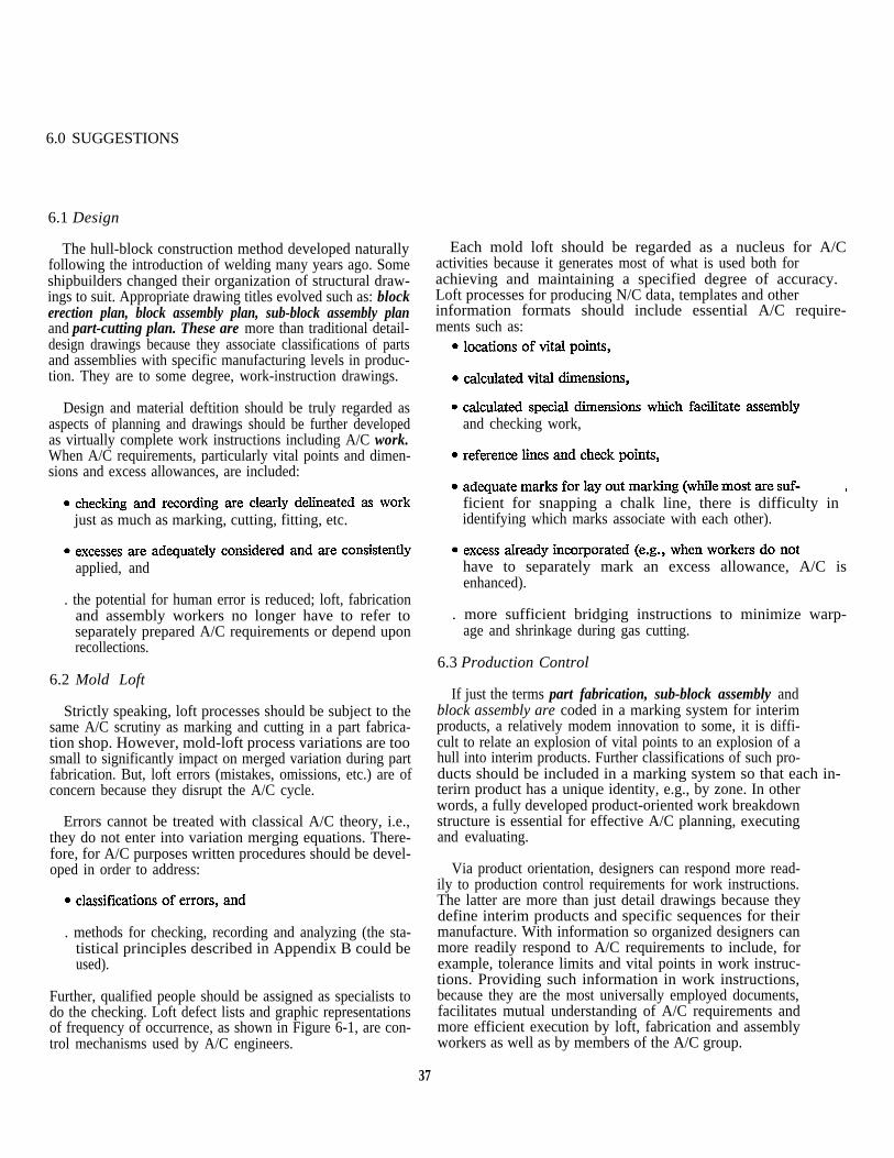
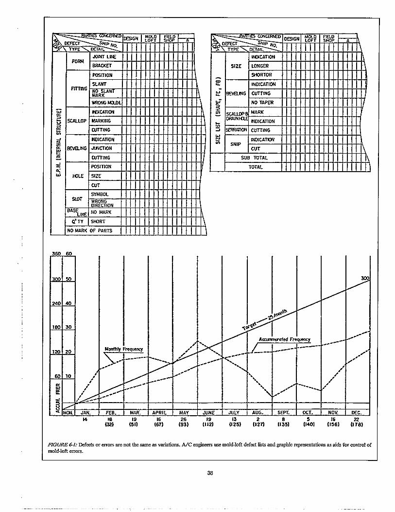
Further, qualified people should be assigned as specialists todo the checking. Loft defect lists and graphic representationsof frequency of occurrence, as shown in Figure 6-1, are con-trol mechanisms used by A/C engineers.
Each mold loft should be regarded as a nucleus for A/Cactivities because it generates most of what is used both forachieving and maintaining a specified degree of accuracy. Loft processes for producing N/C data, templates and otherinformation formats should include essential A/C require-ments such as:
and checking work,
ficient for snapping a chalk line, there is difficulty in identifying which marks associate with each other).
have to separately mark an excess allowance, A/C isenhanced).
. more sufficient bridging instructions to minimize warp-age and shrinkage during gas cutting.
6.3 Production Control
If just the terms part fabrication, sub-block assembly andblock assembly are coded in a marking system for interimproducts, a relatively modem innovation to some, it is diffi-cult to relate an explosion of vital points to an explosion of ahull into interim products. Further classifications of such pro-ducts should be included in a marking system so that each in- terirn product has a unique identity, e.g., by zone. In otherwords, a fully developed product-oriented work breakdownstructure is essential for effective A/C planning, executingand evaluating.
Via product orientation, designers can respond more read-ily to production control requirements for work instructions.The latter are more than just detail drawings because theydefine interim products and specific sequences for theirmanufacture. With information so organized designers canmore readily respond to A/C requirements to include, forexample, tolerance limits and vital points in work instruc-tions. Providing such information in work instructions,because they are the most universally employed documents,facilitates mutual understanding of A/C requirements andmore efficient execution by loft, fabrication and assemblyworkers as well as by members of the A/C group.
37

6.9.3 Ways to Distribute Excess vs. Assembly Sequences
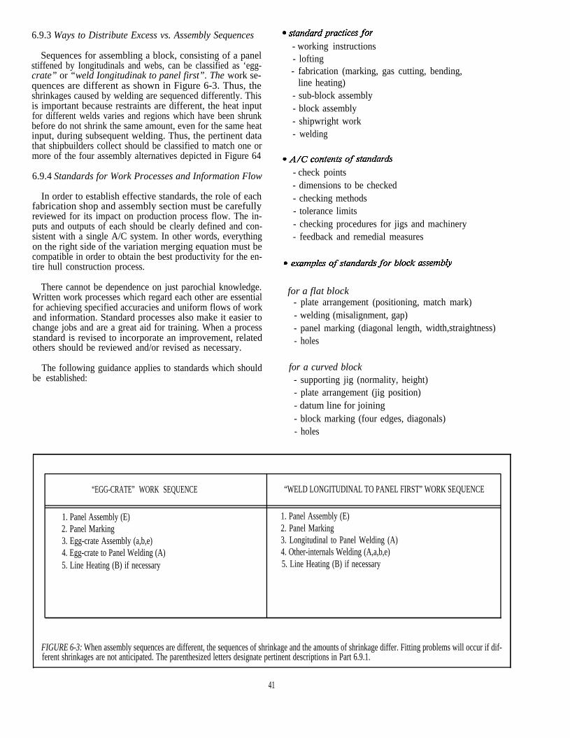
Sequences for assembling a block, consisting of a panelstiffened by Iongitudinals and webs, can be classified as ‘egg-crate” or “weld Iongitudinak to panel first”. The work se-quences are different as shown in Figure 6-3. Thus, theshrinkages caused by welding are sequenced differently. Thisis important because restraints are different, the heat inputfor different welds varies and regions which have been shrunkbefore do not shrink the same amount, even for the same heatinput, during subsequent welding. Thus, the pertinent datathat shipbuilders collect should be classified to match one ormore of the four assembly alternatives depicted in Figure 64
6.9.4 Standards for Work Processes and Information Flow
In order to establish effective standards, the role of eachfabrication shop and assembly section must be carefullyreviewed for its impact on production process flow. The in-puts and outputs of each should be clearly defined and con-sistent with a single A/C system. In other words, everythingon the right side of the variation merging equation must becompatible in order to obtain the best productivity for the en-tire hull construction process.
- working instructions- lofting- fabrication (marking, gas cutting, bending,
line heating)- sub-block assembly- block assembly- shipwright work- welding
- check points- dimensions to be checked- checking methods- tolerance limits- checking procedures for jigs and machinery- feedback and remedial measures
There cannot be dependence on just parochial knowledge.Written work processes which regard each other are essential
for a flat block
for achieving specified accuracies and uniform flows of work - plate arrangement (positioning, match mark)
and information. Standard processes also make it easier to - welding (misalignment, gap)change jobs and are a great aid for training. When a process - panel marking (diagonal length,standard is revised to incorporate an improvement, related - holesothers should be reviewed and/or revised as necessary.
The following guidance applies to standards which should for a curved block
width,straightness)
be established: - supporting jig (normality, height)- plate arrangement (jig position)- datum line for joining- block marking (four edges, diagonals)- holes
“EGG-CRATE” WORK SEQUENCE “WELD LONGITUDINAL TO PANEL FIRST” WORK SEQUENCE
1. Panel Assembly (E) 1. Panel Assembly (E)2. Panel Marking 2. Panel Marking3. Egg-crate Assembly (a,b,e) 3. Longitudinal to Panel Welding (A)4. Egg-crate to Panel Welding (A) 4. Other-internals Welding (A,a,b,e)5. Line Heating (B) if necessary 5. Line Heating (B) if necessary
FIGURE 6-3: When assembly sequences are different, the sequences of shrinkage and the amounts of shrinkage differ. Fitting problems will occur if dif-ferent shrinkages are not anticipated. The parenthesized letters designate pertinent descriptions in Part 6.9.1.
41


APPENDIX A
PLANNING VITAL POINTS FOR A BULK CARRIER
I. Identifying Vital Points
A. Basic
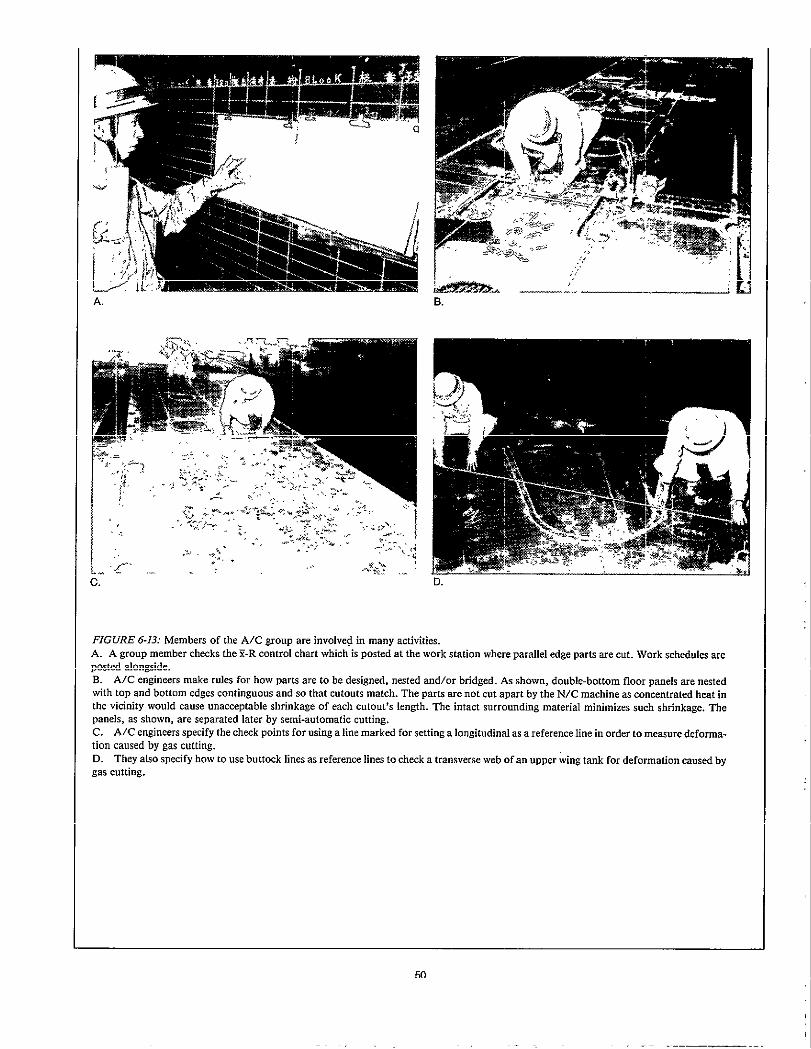
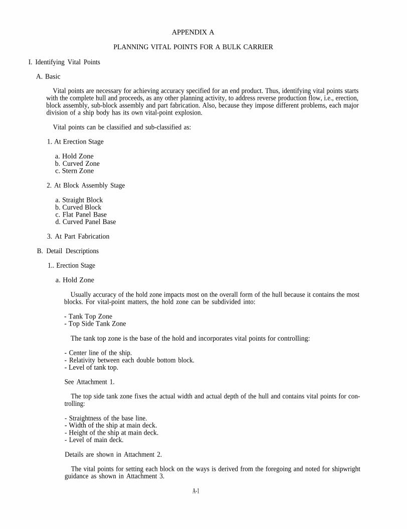
Vital points are necessary for achieving accuracy specified for an end product. Thus, identifying vital points startswith the complete hull and proceeds, as any other planning activity, to address reverse production flow, i.e., erection,block assembly, sub-block assembly and part fabrication. Also, because they impose different problems, each majordivision of a ship body has its own vital-point explosion.
Vital points can be classified and sub-classified as:
1. At Erection Stage
a. Hold Zoneb. Curved Zonec. Stern Zone
2. At Block Assembly Stage
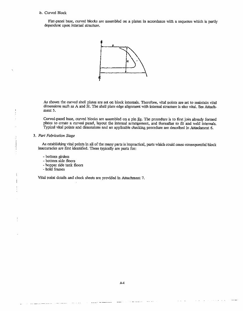
a. Straight Blockb. Curved Blockc. Flat Panel Based. Curved Panel Base
3. At Part Fabrication
B. Detail Descriptions
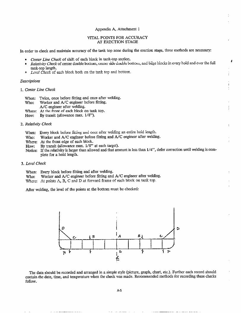
1.. Erection Stage
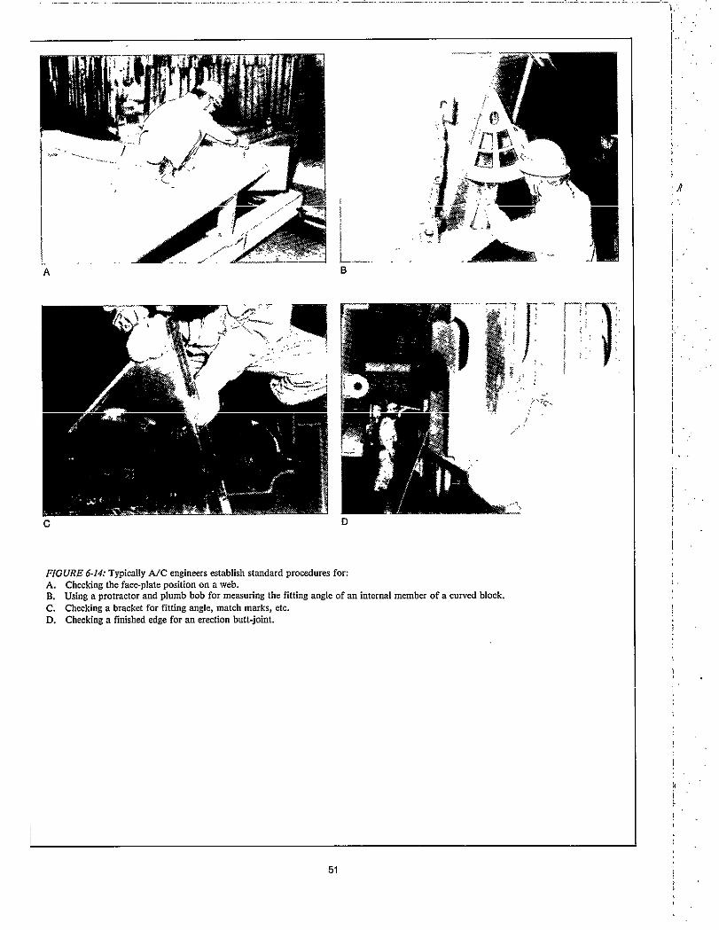
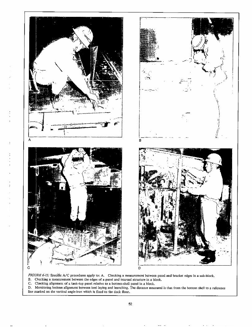
a. Hold Zone
Usually accuracy of the hold zone impacts most on the overall form of the hull because it contains the mostblocks. For vital-point matters, the hold zone can be subdivided into:
- Tank Top Zone- Top Side Tank Zone
The tank top zone is the base of the hold and incorporates vital points for controlling:
- Center line of the ship.- Relativity between each double bottom block.- Level of tank top.
See Attachment 1.
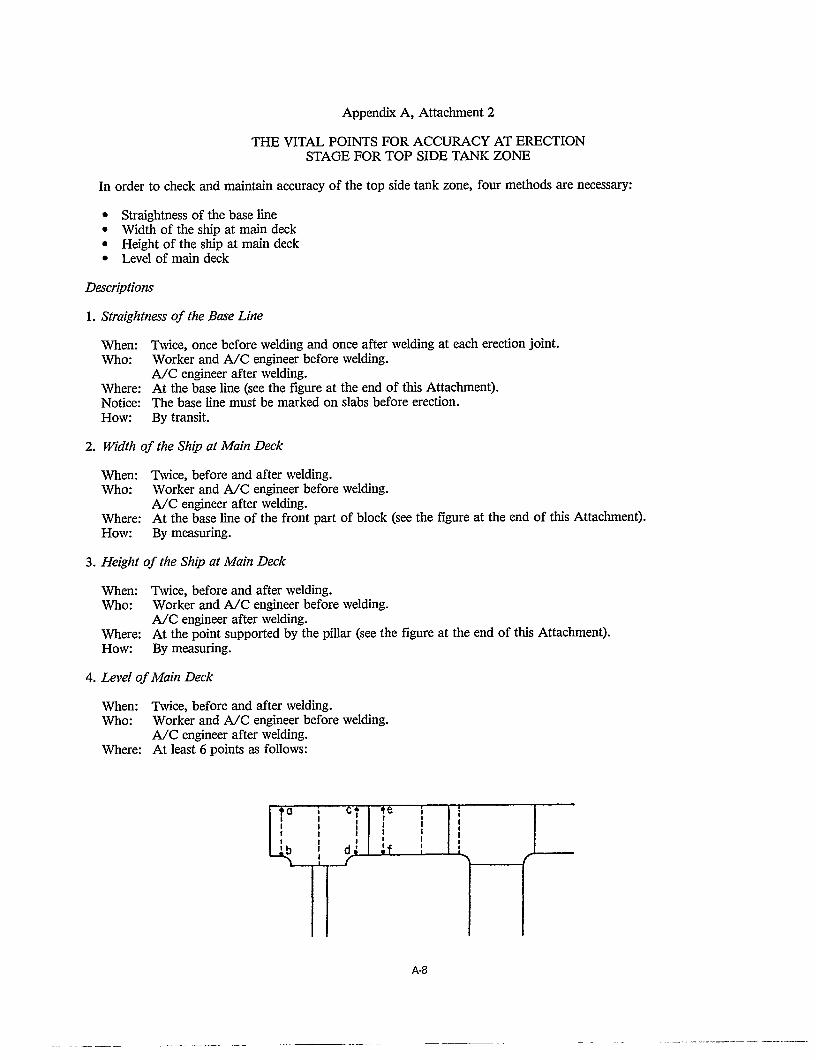
The top side tank zone fixes the actual width and actual depth of the hull and contains vital points for con-trolling:
- Straightness of the base line.- Width of the ship at main deck.- Height of the ship at main deck.- Level of main deck.
Details are shown in Attachment 2.
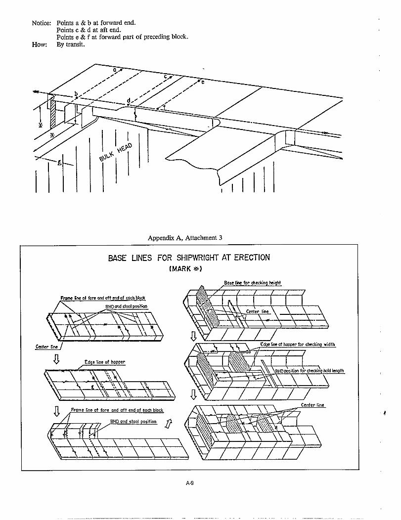
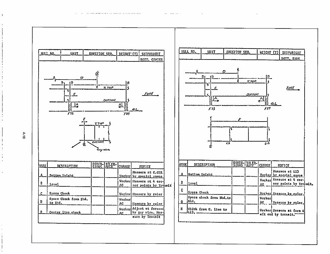
The vital points for setting each block on the ways is derived from the foregoing and noted for shipwrightguidance as shown in Attachment 3.
A-1


APPENDIX D-1
Page D-2 of this Appendix contains a sample from the “Japanese Shipbuilding Quality Standard (Hull Part) -1979”;published by the Research Committee on Steel Shipbuilding, The Society of Naval Architects of Japan, 15-16 Toranomon,l-Chome, Minato-ku, Tokyo, Japan. Standard ranges and tolerance limits are identified for each item.
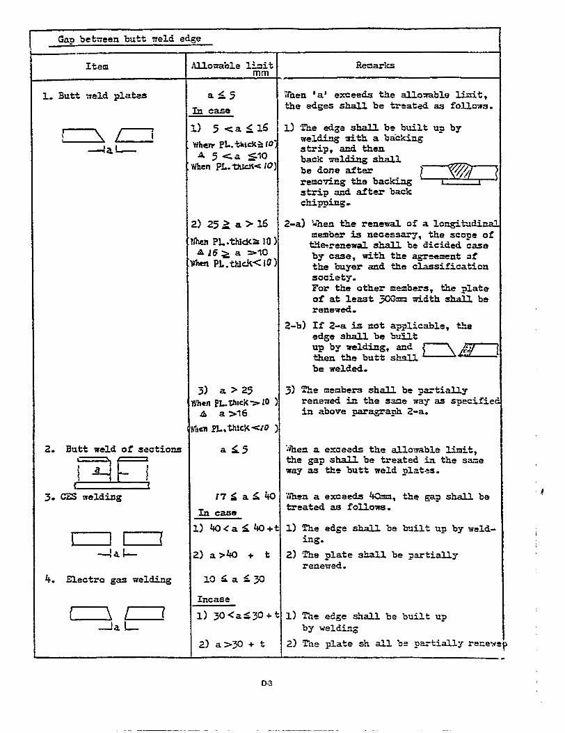
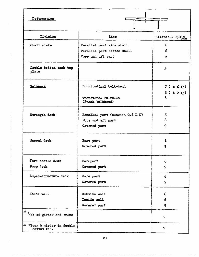
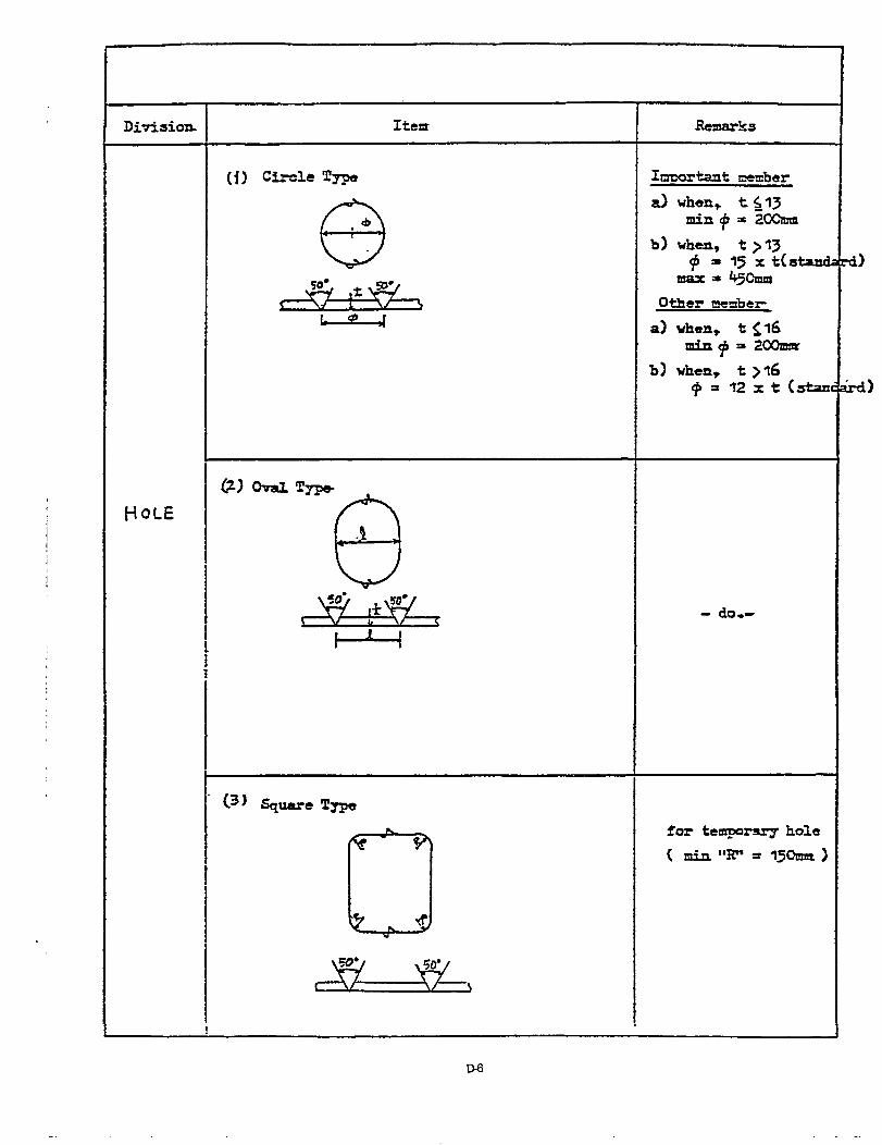
Pages D-3 through D-6 show how such accuracy standards were further developed by a shipbuilding firm.
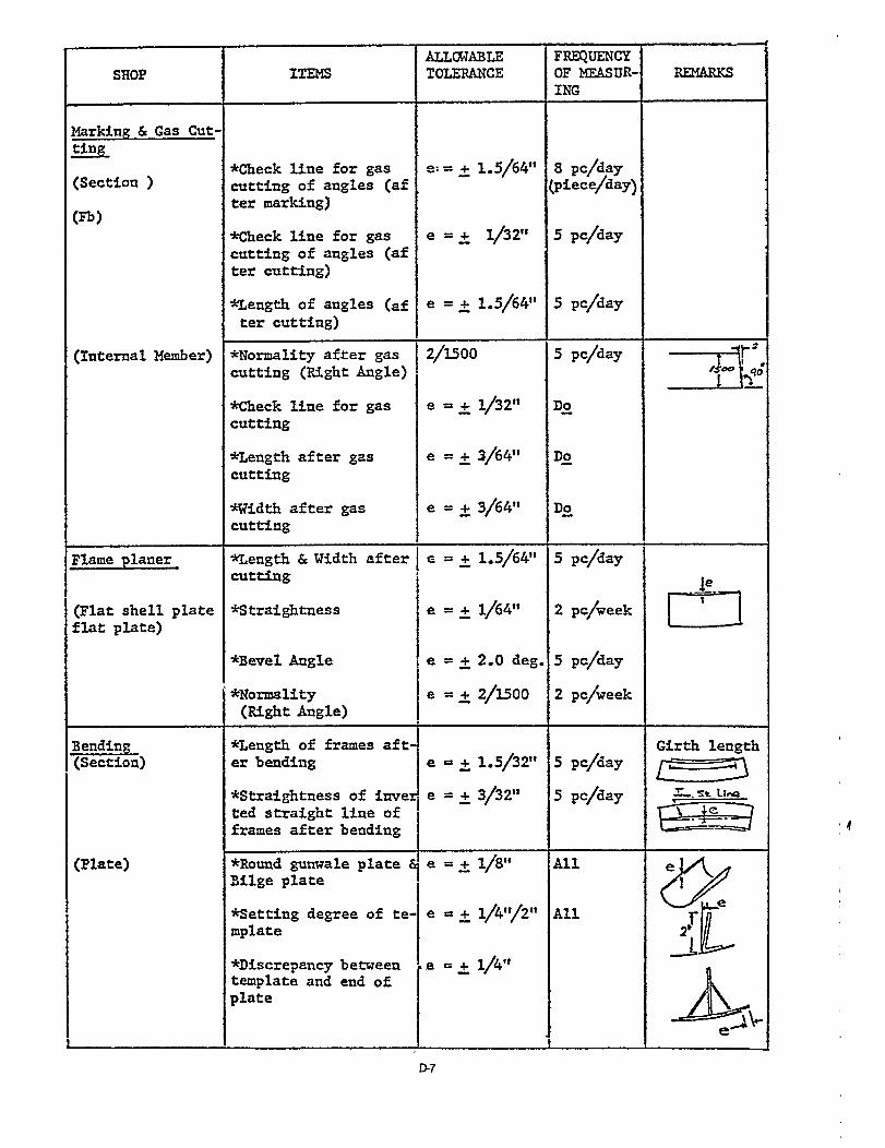
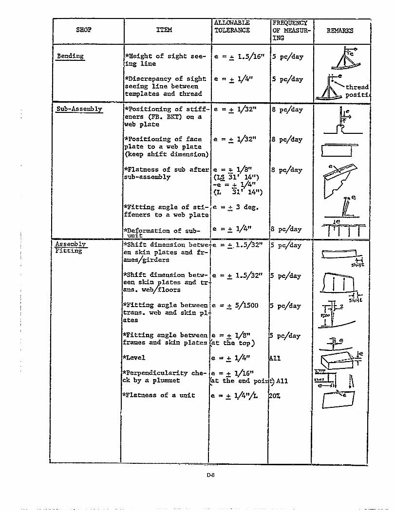
Pages D-7 through D-10 are additional examples of independent accuracy standards development. These also specify“Frequency of Measurement.”

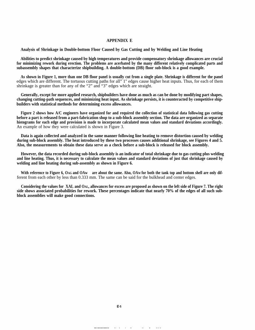
APPENDIX E
Analysis of Shrinkage in Double-bottom Floor Caused by Gas Cutting and by Welding and Line Heating
Abilities to predict shrinkage caused by high temperatures and provide compensatory shrinkage allowances are crucialfor minimizing rework during erection. The problems are acerbated by the many different relatively complicated parts andsubassembly shapes that characterize shipbuilding. A double-bottom (DB) floor sub-block is a good example.
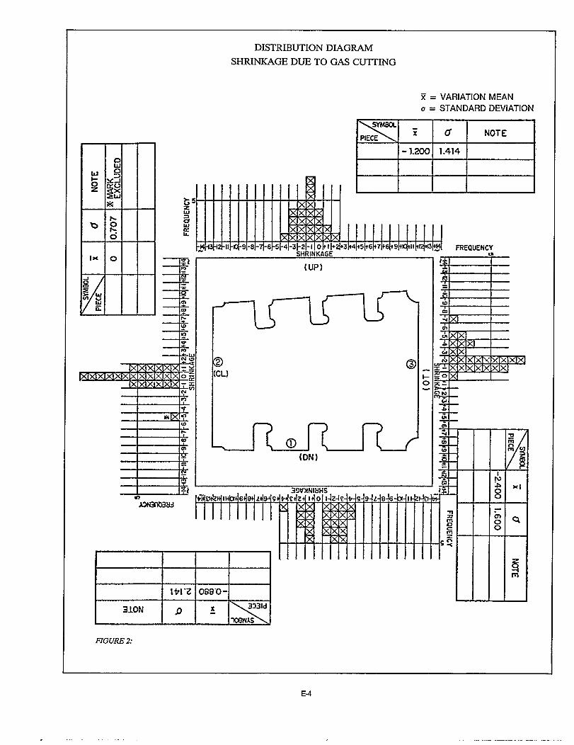
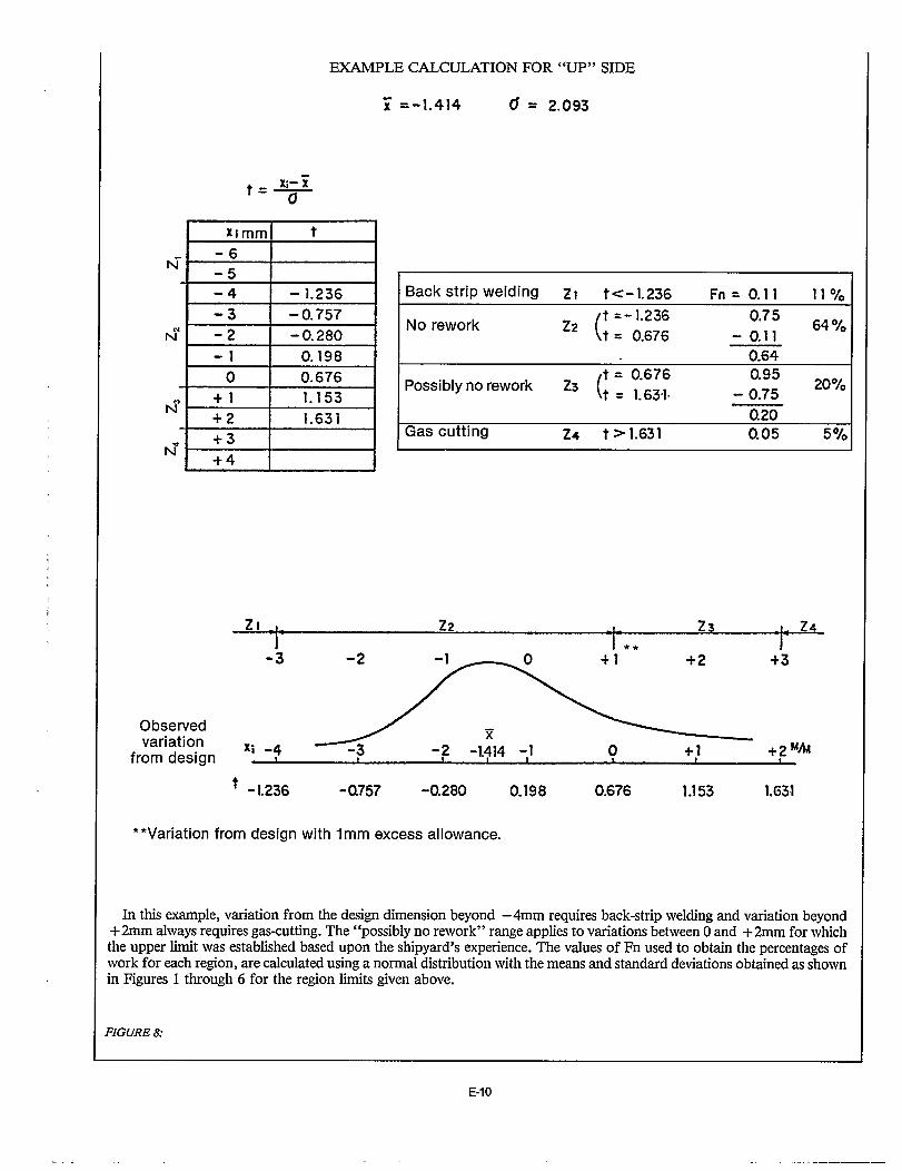
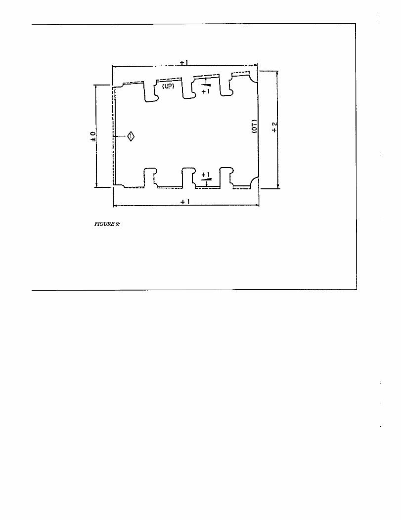
As shown in Figure 1, more than one DB floor panel is usually cut from a single plate. Shrinkage is different for the paneledges which are different. The tortuous cutting paths for all” 1" edges cause higher heat inputs. Thus, for each of themshrinkage is greater than for any of the “2” and “3” edges which are straight.
Generally, except for more applied research, shipbuilders have done as much as can be done by modifying part shapes,changing cutting-path sequences, and minimizing heat input. As shrinkage persists, it is counteracted by competitive ship-builders with statistical methods for determining excess allowances.
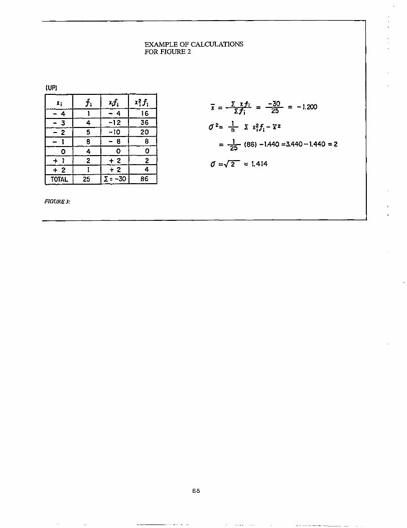
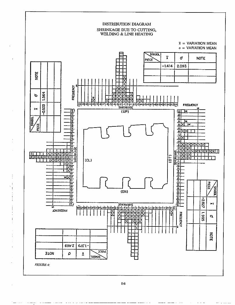
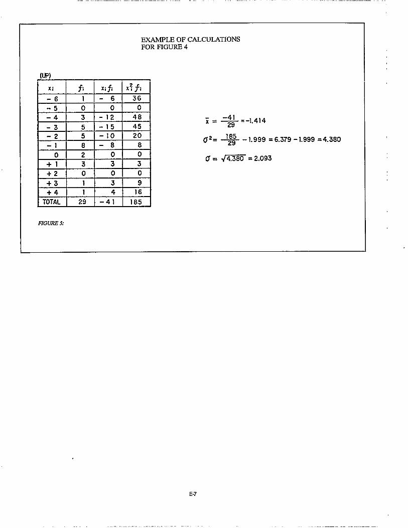
Figure 2 shows how A/C engineers have organized for and required the collection of statistical data following gas cuttingbefore a part is released from a part-fabrication shop to a sub-block assembly section. The data are organized as separatehistograms for each edge and provision is made to incorporate calculated mean values and standard deviations accordingly.An example of how they were calculated is shown in Figure 3.
Data is again collected and analyzed in the same manner following line heating to remove distortion caused by weldingduring sub-block assembly. The heat introduced by these two processes causes additional shrinkage, see Figures 4 and 5.Also, the measurements to obtain these data serve as a check before a sub-block is released for block assembly.
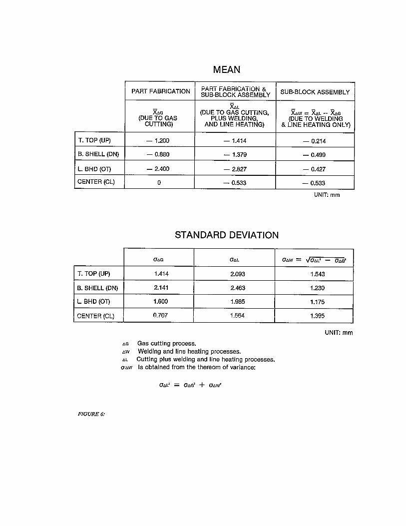
However, the data recorded during sub-block assembly is an indicator of total shrinkage due to gas cutting plus weldingand line heating. Thus, it is necessary to calculate the mean values and standard deviations of just that shrinkage caused bywelding and line heating during sub-assembly as shown in Figure 6.
With reference to Figure 6, OAG and OAw are about the same. Also, OAW for both the tank top and bottom shell are only dif-ferent from each other by less than 0.333 mm. The same can be said for the bulkhead and center edges.
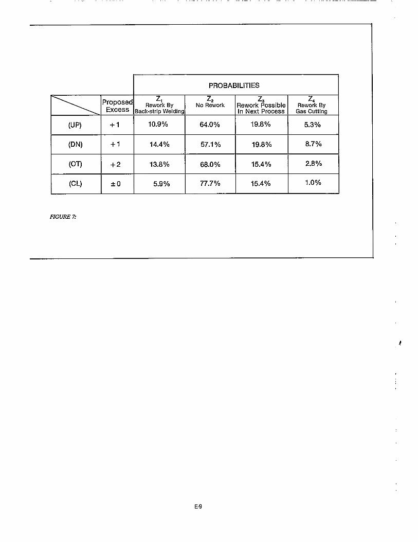
Considering the values for XAL and OAL, allowances for excess are proposed as shown on the left side of Figure 7. The rightside shows associated probabilities for rework. These percentages indicate that nearly 70% of the edges of all such sub-block assemblies will make good connections.


APPENDIX F
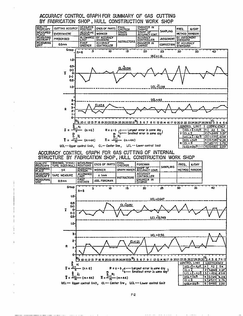
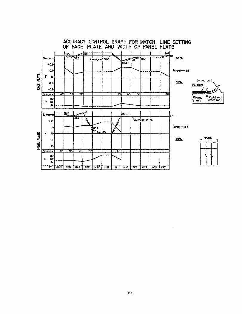
CONTROL CHARTS
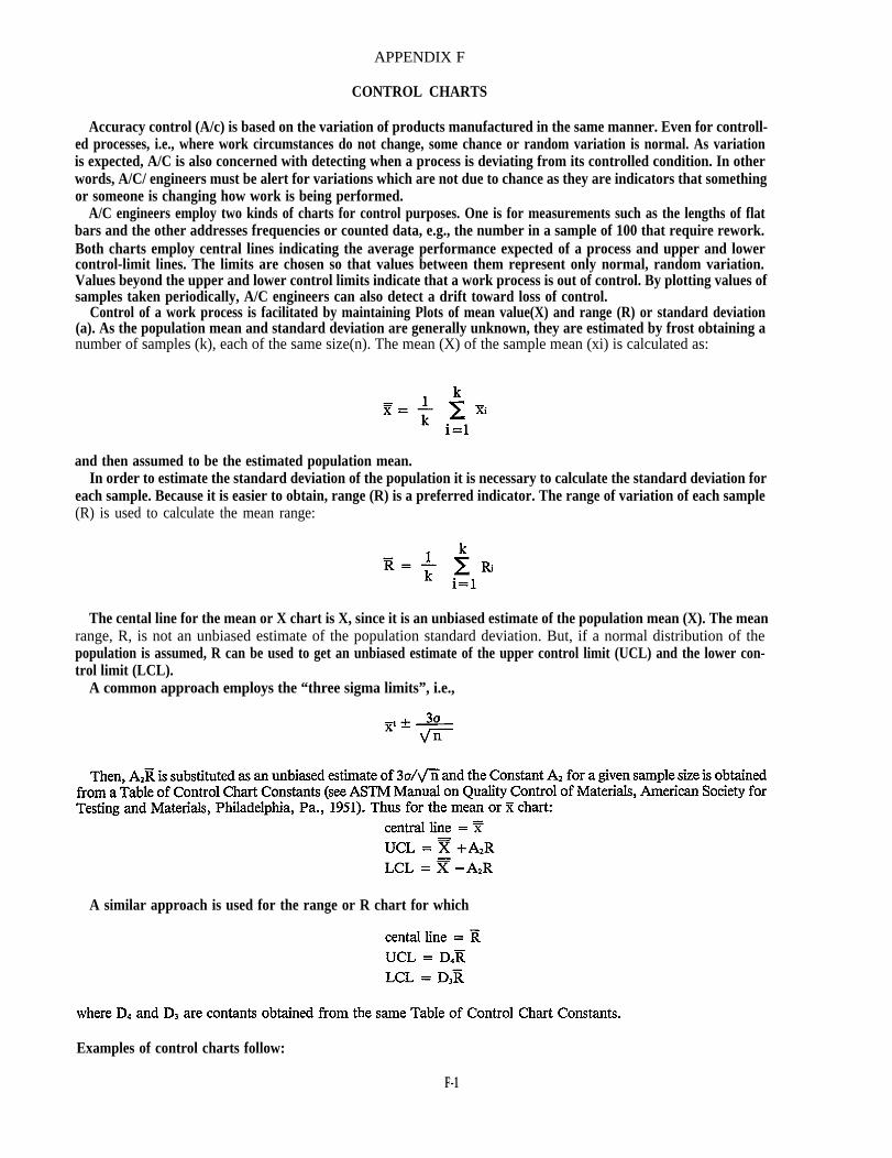
Accuracy control (A/c) is based on the variation of products manufactured in the same manner. Even for controll-ed processes, i.e., where work circumstances do not change, some chance or random variation is normal. As variationis expected, A/C is also concerned with detecting when a process is deviating from its controlled condition. In otherwords, A/C/ engineers must be alert for variations which are not due to chance as they are indicators that somethingor someone is changing how work is being performed.
A/C engineers employ two kinds of charts for control purposes. One is for measurements such as the lengths of flatbars and the other addresses frequencies or counted data, e.g., the number in a sample of 100 that require rework.Both charts employ central lines indicating the average performance expected of a process and upper and lowercontrol-limit lines. The limits are chosen so that values between them represent only normal, random variation.Values beyond the upper and lower control limits indicate that a work process is out of control. By plotting values ofsamples taken periodically, A/C engineers can also detect a drift toward loss of control.
Control of a work process is facilitated by maintaining Plots of mean value(X) and range (R) or standard deviation(a). As the population mean and standard deviation are generally unknown, they are estimated by frost obtaining anumber of samples (k), each of the same size(n). The mean (X) of the sample mean (xi) is calculated as:
and then assumed to be the estimated population mean.In order to estimate the standard deviation of the population it is necessary to calculate the standard deviation for
each sample. Because it is easier to obtain, range (R) is a preferred indicator. The range of variation of each sample(R) is used to calculate the mean range:
The cental line for the mean or X chart is X, since it is an unbiased estimate of the population mean (X). The meanrange, R, is not an unbiased estimate of the population standard deviation. But, if a normal distribution of thepopulation is assumed, R can be used to get an unbiased estimate of the upper control limit (UCL) and the lower con-trol limit (LCL).
A common approach employs the “three sigma limits”, i.e.,
A similar approach is used for the range or R chart for which
Examples of control charts follow:
F-1