U.S. Department of the Interior Cover Page Bureau of Land ... Standard Radio Site Design...
27
Standard Radio Facility Design - Cross Walk Document Ted Sumners - 02/28/2013 Table of Contents Introduction Reference Tables Radio Site Designs Prefabricated Shelter Tower Designs Aluminum Shelter with Articulating Antenna Mast Outdoor Equipment Cabinet Fiberglass Shelter with Antenna Radome External Grounding Commercial Electrical Power Internal Grounding Battery Backup Systems Photovoltaic Electrical Power Cover Page U.S. Department of the Interior Bureau of Land Management RI CASHE Program Standard Land Mobile Radio Facility Design Crosswalk Document February 28, 2013 Produced by Mindbank Consulting Group, LLC Under contract to Aarcher, Inc. Tower Designs provided by Aero Solutions, LLC
Transcript of U.S. Department of the Interior Cover Page Bureau of Land ... Standard Radio Site Design...

Standard Radio Facility Design - Cross Walk Document
Ted Sumners - 02/28/2013
Table of Contents
Introduction
Reference Tables
Radio Site Designs
Prefabricated Shelter
Tower Designs
Aluminum Shelter
with Articulating
Antenna Mast
Outdoor Equipment
Cabinet
Fiberglass Shelter
with Antenna Radome
External Grounding
Commercial Electrical
Power
Internal Grounding
Battery Backup
Systems
Photovoltaic Electrical
Power
Cover Page U.S. Department of the Interior
Bureau of Land Management
RI CASHE Program
Standard Land Mobile Radio Facility Design
Crosswalk Document February 28, 2013
Produced by Mindbank Consulting Group, LLC
Under contract to Aarcher, Inc.
Tower Designs provided by Aero Solutions, LLC
Standard Radio Facility Design - Cross Walk Document
Ted Sumners - 02/28/2013
Table of Contents
Introduction
Reference Tables
Radio Site Designs
Prefabricated Shelter
Tower Designs
Aluminum Shelter
with Articulating
Antenna Mast
Outdoor Equipment
Cabinet
Fiberglass Shelter
with Antenna Radome
External Grounding
Commercial Electrical
Power
Internal Grounding
Battery Backup
Systems
Photovoltaic Electrical
Power
Table of Contents
Introduction
Navigation Tools
RI CASHE Web-Based Discussions
Key Personnel
Purpose of the Standard Radio Facility Design
Radio Facility Design Scope of Work
Radio Facility Design Standards
Typical Radio Facility Designs
Third Party Testing and Inspection Requirements
Standard Radio Facility Design Contacts
Reference Tables
• Facility Component Crosswalk Table
• External Grounding Crosswalk Table
• Internal Grounding Crosswalk Table
• Electrical Crosswalk Table
Radio Facility Designs
• Specifications Format
• Specifications Outlines
• Radio Facility Design Inclusions/Exclusions
• Radio Facility Typical Design Drawings and Workbooks
• Conceptual Design
• Radio Facility Candidate Search
Preliminary Civil Design
Preliminary Communications Equipment Shelter Design
Preliminary Tower Design – Obstruction Evaluation
Final Design of a Radio Facility
Prefabricated Shelter
Typical Shelter – Design Variables
Typical Shelter – Selection Considerations
Typical Shelter – Devices
Typical Shelter – Delivery Considerations
Typical Shelter – Design Options
Typical Shelter – Lighting
Typical Shelter – Air Conditioner Design
Typical 8-foot wide, 12-foot long shelter
Drawing Files for an 8-foot wide, 12-foot long shelter
Prefabricated Shelter (cont.)
Typical 8-foot wide, 16-foot long shelter
Drawing Files for an 8-foot wide, 16-foot long shelter
Tower Designs
Minimum Tower Design Requirements
Example Tower Designs
Tower Design Standards
Tower Design – Classification
Tower Design – Exposure Categories
Tower Design – Topographic Categories
Typical Tower Design Assumptions
Typical Tower Design Loading Criteria
Tower Foundation Design Requirements
Typical Self-Supporting Tower – Antenna Loading Assumptions
Typical SST – 40-foot Designed for Growth to 60-Foot
Typical SST – 60-foot Designed for Growth to 80-Foot
Typical Self-Supporting Tower Assemblies
Typical Self-Supporting Tower Foundations
Typical Flanged Monopole – Antenna Loading Assumptions
Typical Monopole – 40-foot Designed for Growth to 60-Foot
Typical Monopole – 60-foot Designed for Growth to 80-Foot
Typical Flanged Monopole Tower Assemblies
Typical Flanged Monopole Tower Foundation
Antenna Installation – Man-rated Standoff Brackets
Existing Tower Design Requirements
Aluminum Shelter with Articulating Antenna Mast
Aluminum Shelter – Design Variables
Typical 8-foot wide, 12-foot long Aluminum Shelter
Typical 8-foot wide, 16-foot long Aluminum Shelter
Outdoor Equipment Cabinet
Outdoor Equipment Cabinet with 15-foot Pipe-Mast
Outdoor Equipment Cabinet Grounding Design
Fiberglass Shelter with Antenna Radome
Fiberglass Shelter With Antenna Radome – Design
Fiberglass Shelter With Antenna Radome – Grounding Design
External Grounding
External Grounding System Requirements
External Ground Ring – Installation Requirements
Grounding Metallic Ancillary Devices
Tower Ground Bus Bar (TGB)
External Ground Bus Bar (EGB)
Internal Grounding
Internal Shelter Grounding System
Internal Grounding System – Typical Design Drawing
Master Ground Bus Bar
copper-integrated Entry Panel
Bonding Equipment to the Internal Grounding System
Commercial Electrical Power
Commercial Electrical Power – Service
Commercial Electrical Power – Service-Disconnect
Commercial Electrical Power – Surge Protection
Commercial Electrical Power – Panel Boards
Commercial Electrical Power – Distribution
Backup Battery Systems
Battery Installation
Battery Backup System Components
Battery Backup System Design
Typical Battery Backup System Drawings
Photovoltaic Electrical Power
Photovoltaic Electrical Power – Designs
Battery Storage Systems on Photovoltaic Powered Facilities
Battery Storage System Designs
Battery Installation
Typical Component Power Consumption
Budgetary Photovoltaic Calculation Assumptions
Example 20 to 30-Ampere Photovoltaic System Calculations
Example 30-Ampere Photovoltaic System Drawing
Example 30 to 60-Ampere Photovoltaic System Calculations
Example 60-Ampere Photovoltaic System Drawing
Solar Panel Grounding
Maps of Average Daily Solar Radiation Annually
Maps of Average Daily Solar Radiation per Month
Table of Contents

Standard Radio Facility Design - Cross Walk Document
Ted Sumners - 02/28/2013
Table of Contents
Introduction
Reference Tables
Radio Site Designs
Prefabricated Shelter
Tower Designs
Aluminum Shelter
with Articulating
Antenna Mast
Outdoor Equipment
Cabinet
Fiberglass Shelter
with Antenna Radome
External Grounding
Commercial Electrical
Power
Internal Grounding
Battery Backup
Systems
Photovoltaic Electrical
Power
Navigation Tools
Crosswalk Document Section Icons: Section icons provided along the right side of each page of the Crosswalk Document allow the
user to navigate to a particular standard design topic.
Inactive Page Icon – Click on icon to navigate to the Crosswalk Document topic
Active Page Icon – Shows the current Crosswalk Document topic the user is reviewing
Bullet Icons are provided throughout the Crosswalk Document:
Clicking on ADOBE icons allows the user to open the associated files in Adobe Reader.
Clicking on WORD icons allows the user to open the associated files in MS Word.
Hovering your mouse over NOTES icons provides addition information on the topic discussed.
Clicking on the CAMERA Icon will open photos associated with the topic.
Clicking on the BLM LOGO opens the RI CASHE web-based discussion relevant to the topic.
Clicking on the DOLLAR ICON will open up pricing estimates for the standard configuration type.
Underlined Text provides links to external web sites, Motorola R56 pages or to documents contained on the Crosswalk Document
Disc.
Images: Hovering your mouse over images provides additional information. Clicking on images opens a full size file.
Introduction

Standard Radio Facility Design - Cross Walk Document
Ted Sumners - 02/28/2013
Table of Contents
Introduction
Reference Tables
Radio Site Designs
Prefabricated Shelter
Tower Designs
Aluminum Shelter
with Articulating
Antenna Mast
Outdoor Equipment
Cabinet
Fiberglass Shelter
with Antenna Radome
External Grounding
Commercial Electrical
Power
Internal Grounding
Battery Backup
Systems
Photovoltaic Electrical
Power
RI CASHE Web-Based Discussions
The RI CASHE Standard website is a resource for land mobile radio
(LMR) facility managers responsible for understanding and implementing
corrective action requirements identified through site assessment and
audit programs. This is not intended as a comprehensive reference site,
but rather a repository of individual explanatory pages referenced from
assessment/audit findings. If a report link is not functional or you have
other questions regarding the function or operation of this site, please see
the Contact section of this site.
Contents of the RI CASHE Standard website is accessed directly through
links contained throughout this document. Clicking on the BLM icon links
the user to a web-based forum where discussions regarding regulatory
compliance, BLM-specific requirements, and links to the Motorola R56
citations are provided.
The topics are customized to provide the reader with additional
information and resources to aid in design of a new radio facility or effect
corrective actions on existing facilities.
Each web-based topic has the relevant driving references governing the
proper installation or requirement. Each web-based topic will have links to
the specific Motorola R56 citation.
Some topics provide links to vendor web sites that identify materials
needed to add in the bill of materials.
To register for a login user name and password, click on the link below.
Self-Register for RI CASHE Standards
Introduction
Standard Radio Facility Design - Cross Walk Document
Ted Sumners - 02/28/2013
Table of Contents
Introduction
Reference Tables
Radio Site Designs
Prefabricated Shelter
Tower Designs
Aluminum Shelter
with Articulating
Antenna Mast
Outdoor Equipment
Cabinet
Fiberglass Shelter
with Antenna Radome
External Grounding
Commercial Electrical
Power
Internal Grounding
Battery Backup
Systems
Photovoltaic Electrical
Power
BLM RI CASHE PROGRAM
Compliance Assessment-Safety, Health, and the Environment
Primary Contacts:
Ken Morin – BLM CASHE Program Lead [email protected]
Jason Becker – BLM National Radio Operations Branch [email protected]
Mindbank Consulting Group, LLC – Subcontracted to Aarcher providing specialized knowledge of radio facilities
Experience with tower audit programs for government agencies
Experience with design and construction of wireless radio facilities
Primary Contact:
Ted Sumners – RI CASHE Project Manager [email protected]
Aarcher, Inc. – Prime contractor for the BLM CASHE Program
Environmental consultants and regulatory compliance experts
Manages BLM CASHE and RI CASHE Programs
Primary Contact:
Bonnie Wisniewski – Aarcher CASHE Program Manager [email protected]
Aero Solutions, LLC – Subcontracted to Mindbank providing professional engineering services for tower designs
Key Personnel
Introduction

Standard Radio Facility Design - Cross Walk Document
Ted Sumners - 02/28/2013
Table of Contents
Introduction
Reference Tables
Radio Site Designs
Prefabricated Shelter
Tower Designs
Aluminum Shelter
with Articulating
Antenna Mast
Outdoor Equipment
Cabinet
Fiberglass Shelter
with Antenna Radome
External Grounding
Commercial Electrical
Power
Internal Grounding
Battery Backup
Systems
Photovoltaic Electrical
Power
The standard designs provide templates for use by engineers, radio technicians, and management that
provide the following:
Specifications documents
Provides interpretations of industry design standards specifically for land mobile radio facilities
Specifies installation materials to be used
Specifies installation methods and requirements
Provides cross references to Motorola R 56 sections, DOI checklist questions, and regulatory
standards
Typical design drawings
Provides a graphical representation of specifications for each typical radio facility type
Provides a standard template in AutoCAD format for use during radio facility development and
planning
Estimated budgetary pricing:
Provides detailed pricing for materials and labor for each typical radio facility type
Provides a budgetary tool for future planning
Crosswalk document
Provides detailed descriptions, photographs, drawings and guidance on where, how and why
devices are installed
Provides links to specifications documents, design drawings, pricing, and other resources
Provides links to feature-rich web discussions regarding regulatory and industry design
standards
Purpose of the Standard Radio Facility Design
Introduction

Standard Radio Facility Design - Cross Walk Document
Ted Sumners - 02/28/2013
Table of Contents
Introduction
Reference Tables
Radio Site Designs
Prefabricated Shelter
Tower Designs
Aluminum Shelter
with Articulating
Antenna Mast
Outdoor Equipment
Cabinet
Fiberglass Shelter
with Antenna Radome
External Grounding
Commercial Electrical
Power
Internal Grounding
Battery Backup
Systems
Photovoltaic Electrical
Power
Develop plans and specifications for a standard radio facility that is fully compliant with the requirements in the Department of the
Interior’s Office of the Chief of Information Office (OCIO) Directive 2009-008, signed on December 9, 2009.
The OCIO directive references numerous industry and regulatory standards the bureaus are to follow when designing,
constructing, or operating a radio facility. Those standards include, but are not limited to, the following:
Occupational Safety and Health Administration (OSHA)
Motorola R56 Committee
Electronic Industries Alliance/Telecommunications Industry Association (EIA/TIA)
American National Standards Institute (ANSI)
National Fire Prevention Association (NFPA)
A lengthy list of specific standards is provided in the OCIO Directive. The standard radio facility design is not limited to using
only the standards identified in the OCIO Directive. New applicable or more recent standards are to be used, as well.
The BLM RI CASHE Program has deviated from some Motorola R56 requirements. Those deviations are to be reflected in the
standard design.
The design effort does not include installation of radio frequency (RF) cabling or radio equipment. However, the standard
design includes installation of infrastructure in the shelter, on the tower and between the shelter and tower to support
installation of RF cabling, antennas, and radio equipment.
Radio Facility Design Scope of Work
Introduction

Standard Radio Facility Design - Cross Walk Document
Ted Sumners - 02/28/2013
Table of Contents
Introduction
Reference Tables
Radio Site Designs
Prefabricated Shelter
Tower Designs
Aluminum Shelter
with Articulating
Antenna Mast
Outdoor Equipment
Cabinet
Fiberglass Shelter
with Antenna Radome
External Grounding
Commercial Electrical
Power
Internal Grounding
Battery Backup
Systems
Photovoltaic Electrical
Power
Department of the Interior OCIO Directive 2009-008
Motorola Reference Manual 56 (Motorola R56)
Standards and Guidelines for Communications Sites (09/01/05).
DOI received authorization from Motorola to utilize excerpts of the Motorola copyrighted Motorola R56
manual.
Occupational Safety and Health Act (OSHA)
National Fire Protection Agency (NFPA)
NFPA 70: National Electrical Code (NEC)
NFPA 780: Standard for the Installation of Lightning Protection Systems
Federal Communications Commission (FCC)
FCC OET Bulletin No. 56
Questions and Answers about Biological Effects and Potential Hazards of Radio Frequency
Electromagnetic Fields
FCC OET Bulletin No. 65
Evaluating Compliance With FCC Guidelines for Human Exposure to Radio Frequency Electromagnetic
Fields
American National Standards Institute (ANSI)
Telecommunications Industry Association (TIA)
Radio Facility Design Standards
Introduction

Standard Radio Facility Design - Cross Walk Document
Ted Sumners - 02/28/2013
Table of Contents
Introduction
Reference Tables
Radio Site Designs
Prefabricated Shelter
Tower Designs
Aluminum Shelter
with Articulating
Antenna Mast
Outdoor Equipment
Cabinet
Fiberglass Shelter
with Antenna Radome
External Grounding
Commercial Electrical
Power
Internal Grounding
Battery Backup
Systems
Photovoltaic Electrical
Power
Plans and specifications developed and discussed in the Crosswalk Document provide for the construction of one of the following radio
communication facility types:
Traditional radio facility using a prefabricated radio equipment shelter with a communications tower
Designs include options for facilities to be powered by commercial power with battery backup or photovoltaic power with battery
storage
Designs include options for variable shelter sizes and types as well as two options for a self-supporting tower or monopole tower
with variable tower heights
Radio facility with a prefabricated aluminum radio equipment shelter equipped with an attached articulating antenna mast
Designs include options for facilities to be powered by commercial power with battery backup or photovoltaic power with battery
storage
The designs include options for variable shelter sizes and antenna mast heights
Radio facility using a prefabricated outdoor radio equipment cabinet with antennas mounted on a pipe-mast powered by photovoltaic
power with battery backup
Radio facility using a prefabricated fiberglass shelter with antennas mounted inside the shelter and powered by photovoltaic power
with battery backup
This is the typical shelter used in the Alaska interior
Prefabricated radio equipment shelter only using commercial power with battery backup
This deliverable is intended to provide the field with a specification it may use to purchase just the shelter
Prefabricated radio equipment shelter only using photovoltaic power with battery backup power
This deliverable is intended to provide the field with a specification it may use to purchase just the shelter
Typical Radio Facility Designs
Introduction

Standard Radio Facility Design - Cross Walk Document
Ted Sumners - 02/28/2013
Table of Contents
Introduction
Reference Tables
Radio Site Designs
Prefabricated Shelter
Tower Designs
Aluminum Shelter
with Articulating
Antenna Mast
Outdoor Equipment
Cabinet
Fiberglass Shelter
with Antenna Radome
External Grounding
Commercial Electrical
Power
Internal Grounding
Battery Backup
Systems
Photovoltaic Electrical
Power
General contractors awarded the construction of new radio facilities or remediation of existing radio facilities must provide a pool of
qualified independent firms to perform review, inspection, and testing services during the construction life cycle.
The government will select the third-party inspector from a pool of at least three qualified inspectors from three different firms
proposed by the Contractor.
Third-party inspector is an individual or company, hired by, but not associated with, the company contracted to construct the radio
site, nor associated with the government. The third-party inspector must possess demonstrated knowledge of LMR site construction
and meet the following qualifications:
The third-party inspector must be radio expert, having a minimum of 15 years of experience with the design, installation,
maintenance, and repair of remote mountain-top LMR radio systems, repeaters, remote controls, multiplexers, antenna systems,
microwave systems, battery backup systems, and solar power systems;
The inspector will possess demonstrable experience and extensive knowledge with radio site construction operations and
maintenance, RF emissions safety, and relevant industry standards and guidelines;
The inspector must have working knowledge of environmental/safety issues typically found at LMR facilities including, but not
limited to, SARA Title III, propane storage, and diesel fuel storage issues associated with emergency power systems (e.g.
batteries and generators); and
The Third Party Inspector must be a member of an inspection team with whom the inspector can consult on complex issues. The
team shall include a qualified radio technician/engineer, and an electrical engineer who specializes in design of grounding
systems at remote mountain-top locations.
Third-party inspectors will provide the following activities:
Review design drawings prior to construction and advise the general contractor and government regarding design compliance
with the standards;
Review of photos of belowgrade or encased site components provided by the general contractor; and
Physical onsite inspection of the radio facility at the completion of construction prior to the government’s final acceptance. This
includes completion of the DOI Radio Communication Site Inspection Checklist and testing the grounding system.
Third-party Testing and Inspection Requirements
Section 01 45 23 – Third Party Testing and Inspecting Services Introduction

Standard Radio Facility Design - Cross Walk Document
Ted Sumners - 02/28/2013
Table of Contents
Introduction
Reference Tables
Radio Site Designs
Prefabricated Shelter
Tower Designs
Aluminum Shelter
with Articulating
Antenna Mast
Outdoor Equipment
Cabinet
Fiberglass Shelter
with Antenna Radome
External Grounding
Commercial Electrical
Power
Internal Grounding
Battery Backup
Systems
Photovoltaic Electrical
Power
Ken Morin, P.E.
Bureau of Land Management
CASHE Program Lead
303-236-6418
Ted Sumners
Technical Evaluation and
Development Services, LLC
303-903-6347
Standard Radio Facility Design Contacts
Introduction

Standard Radio Facility Design - Cross Walk Document
Ted Sumners - 02/28/2013
Table of Contents
Introduction
Reference Tables
Radio Site Designs
Prefabricated Shelter
Tower Designs
Aluminum Shelter
with Articulating
Antenna Mast
Outdoor Equipment
Cabinet
Fiberglass Shelter
with Antenna Radome
External Grounding
Commercial Electrical
Power
Internal Grounding
Battery Backup
Systems
Photovoltaic Electrical
Power
Facility Component – Cross Reference Table
TOPIC SPECIFICATION MOTOROLA R56 REFERENCE CHECKLIST
REFERENCE
Communications Tower Section 33 81 13 2.12 – Tower Design and Construction (2.7, 2.8, 2.9)
Tower Ground Ring Section 33 79 16 4.7.6 – Tower Grounding (4.7)
Tower Ground Bus Bar Section 33 79 86 4.4.3.1 – Tower Ground Bus Bar (4.9)
Prefabricated Communications Shelter Section 13 34 18 3.3 – Building/Shelter Design and Location Considerations (3.6, 3.7)
Shelter Ground Ring Section 33 79 15 4.4.1.6 – External Building and Tower Ground Ring (4.5)
Aluminum Shelter with Articulating Antenna Mast Section 13 34 18.13 3.3 – Building/Shelter Design and Location Considerations (3.6, 3.7)
Shelter Ground Ring Section 33 79 15.23 4.4.1.6 – External Building and Tower Ground Ring (4.5)
Outdoor Cabinet with Embedded 20-foot Antenna Mast Section 13 34 18.13 3.3 – Building/Shelter Design and Location Considerations (3.6, 3.7)
Outdoor Equipment Cabinet Grounding Section 33 79 15.23 4.7.8 – Outdoor Cabinet Grounding (4.5)
Aluminum Cabinet with Articulating Antenna Mast Section 13 34 18.13 3.3 – Building/Shelter Design and Location Considerations (3.6, 3.7)
Outdoor Equipment Cabinet Grounding Section 33 79 15.23 4.7.8 – Outdoor Cabinet Grounding (4.5)
Fiberglass Shelter with Antenna Radome Section 13 34 18.23 3.3 – Building/Shelter Design and Location Considerations (3.6, 3.7)
Shelter Ground Ring Section 33 79 15 4.4.1.6 – External Building and Tower Ground Ring (4.5)
Reference Tables

Standard Radio Facility Design - Cross Walk Document
Ted Sumners - 02/28/2013
Table of Contents
Introduction
Reference Tables
Radio Site Designs
Prefabricated Shelter
Tower Designs
Aluminum Shelter
with Articulating
Antenna Mast
Outdoor Equipment
Cabinet
Fiberglass Shelter
with Antenna Radome
External Grounding
Commercial Electrical
Power
Internal Grounding
Battery Backup
Systems
Photovoltaic Electrical
Power
TOPIC SPECIFICATION MOTOROLA R56 REFERENCE CHECKLIST
REFERENCE
Ancillary Device Grounding Section 33 79 20 4.7.10 – Metallic Objects Requiring Grounding (4.2)
Grounding Electrodes Section 33 79 83.13 4.4.1 – Grounding (Earthing) Electrodes (4.3)
Supplemental Grounding Electrodes Section 33 79 83.20 4.4.1 – Grounding (Earthing) Electrodes (4.3)
Electrolytic Ground Rods Section 33 79 83.33 4.4.1.3 – Electrolytic Ground Rods (4.3)
External Grounding Conductors Section 33 79 83 4.7.10 – Metallic Objects Requiring Grounding (4.4)
Shelter Ground Ring Section 33 79 15 4.4.1,6 – External Building and Tower Ground Ring (4.5)
External Ground Bus Bar Section 33 79 86 4.4.3 – External Ground Bus Bars (4.6)
Tower Ground Ring Section 33 79 16 4.4.1,6 – External Building and Tower Ground Ring (4.7)
Tower Grounding Section 33 79 16 4.7.6 – Tower Grounding (4.8)
Tower Ground Bus Bar Section 33 79 86 4.4.3.1 – Tower Ground Bus Bar (4.9)
Grounding Electrode System Resistance Section 33 79 83.53 4.7.4 – Grounding Electrode System Resistance (4.10)
Special Grounding Situations Section 33 79 83.63 4.11 – Special Grounding Situations (4.11, 4.12, 4.13)
Ice Bridge Grounding Section 33 79 83.23 2.12.8.1 – Ice Bridge and Cable Support Requirements (8.12, 8.13)
External Grounding – Cross Reference Table
Reference Tables

Standard Radio Facility Design - Cross Walk Document
Ted Sumners - 02/28/2013
Table of Contents
Introduction
Reference Tables
Radio Site Designs
Prefabricated Shelter
Tower Designs
Aluminum Shelter
with Articulating
Antenna Mast
Outdoor Equipment
Cabinet
Fiberglass Shelter
with Antenna Radome
External Grounding
Commercial Electrical
Power
Internal Grounding
Battery Backup
Systems
Photovoltaic Electrical
Power
Internal Grounding – Cross Reference Table
TOPIC SPECIFICATION MOTOROLA R56 REFERENCE CHECKLIST
REFERENCE
Internal Grounding System DIVISION 33 5.3 – Grounding System Components and Installation Requirements Section 5
Master Ground Bus Bar Section 33 79 86 5.3.1 – Master Ground Bus (5.1)
Sub System Ground Bus Bar Section 33 79 86 5.3.2 – Sub System Ground Bus Bar (5.1)
Rack Ground Bus Bar Section 33 79 84.16 5.3.5 – Rack Ground Bus Bar (8.3)
Internal Perimeter Ground Bus Section 33 79 85 5.3.7 – Internal Perimeter Ground Bus Conductors (5.2)
Bonding Equipment to the Internal Grounding System Section 33 79 84.13 5.4 – Connection Methods for Internal Grounding (Earthing) System (5.3)
Internal Shelter Grounding Conductors Section 33 79 84 5.4.1 – General Bonding Requirements (5.4)
Reference Tables

Standard Radio Facility Design - Cross Walk Document
Ted Sumners - 02/28/2013
Table of Contents
Introduction
Reference Tables
Radio Site Designs
Prefabricated Shelter
Tower Designs
Aluminum Shelter
with Articulating
Antenna Mast
Outdoor Equipment
Cabinet
Fiberglass Shelter
with Antenna Radome
External Grounding
Commercial Electrical
Power
Internal Grounding
Battery Backup
Systems
Photovoltaic Electrical
Power
Electrical – Cross Reference Table
TOPIC SPECIFICATION MOTOROLA R56 REFERENCE CHECKLIST
REFERENCE
COMMERCIAL POWER DIVISION 26 CHAPTER 6 SECTION 6
Basic Electrical Materials and Methods Section 26 05 00 6.2.7 – Conductors & 6.2.8 - Conduit SECTION 6
Low Voltage Electrical Service Entrance Section 26 21 13 6.2.1 – Electrical Service (6.3, 6.6)
Electricity Metering Section 26 21 13 6.2.1 – Electrical Service (6.3, 6.6)
Panel Boards Section 26 24 16 6.2.5 – Power Panels (6.7, 6.8, 6.9, 6.11)
Electrical Materials Section 26 05 00 6.2.1 – Electrical Service (6.3, 6.6)
SOLAR POWER DIVISION 26 CHAPTER 6 SECTION 6
Photovoltaic Collectors Systems Section 26 31 00 6.6 – Alternate Power sources 6.10
BATTERY BACKUP POWER DIVISION 26 CHAPTER 6 SECTION 6
Battery Systems Section 26 33 00 6.7 – Battery Systems (6.13, 6.14, 6.15)
Reference Tables

Standard Radio Facility Design - Cross Walk Document
Ted Sumners - 02/28/2013
Table of Contents
Introduction
Reference Tables
Radio Site Designs
Prefabricated Shelter
Tower Designs
Aluminum Shelter
with Articulating
Antenna Mast
Outdoor Equipment
Cabinet
Fiberglass Shelter
with Antenna Radome
External Grounding
Commercial Electrical
Power
Internal Grounding
Battery Backup
Systems
Photovoltaic Electrical
Power
Specification documents included in the standard radio facility design have been completed in the Construction Specifications
Institute’s (CSI) MasterFormat®.
MasterFormat®, a publication of CSI and Construction Specifications Canada (CSC), is a master list of numbers and titles
classified by work results. It is primarily used to organize project manuals and detailed cost information, and to relate drawing
notations to specifications.
Construction projects use many different kinds of delivery methods, products, and installation methods, but in common is the need
for effective teamwork by the many parties involved to ensure the correct and timely completion of work. The successful
completion of projects requires effective communication amongst the people involved; and that, in turn, requires easy access to
essential project information. Efficient information retrieval is only possible when a standard filing system is used by everyone.
MasterFormat® provides such a standard filing and retrieval scheme that can be used throughout the construction industry.
MasterFormat® is used to organize specifications and other project information for most commercial building design and
construction projects in North America. It lists titles and section numbers for organizing data about construction requirements,
products, and activities. By standardizing such information, MasterFormat® facilitates communication among architects, specifiers,
contractors, and suppliers, and helps all parties meet radio facility owners’ requirements, timelines, and budgets.
The purpose of this format is to assist the user in locating specific types of information. Information contained in CSI’s
MasterFormat® is organized in a standardized outline form within 50 divisions. Each division contains a number of sections.
Each section is divided into the following three parts:
General
Products
Execution
Specifications Format
Radio Site Designs
Standard Radio Facility Design - Cross Walk Document
Ted Sumners - 02/28/2013
Table of Contents
Introduction
Reference Tables
Radio Site Designs
Prefabricated Shelter
Tower Designs
Aluminum Shelter
with Articulating
Antenna Mast
Outdoor Equipment
Cabinet
Fiberglass Shelter
with Antenna Radome
External Grounding
Commercial Electrical
Power
Internal Grounding
Battery Backup
Systems
Photovoltaic Electrical
Power
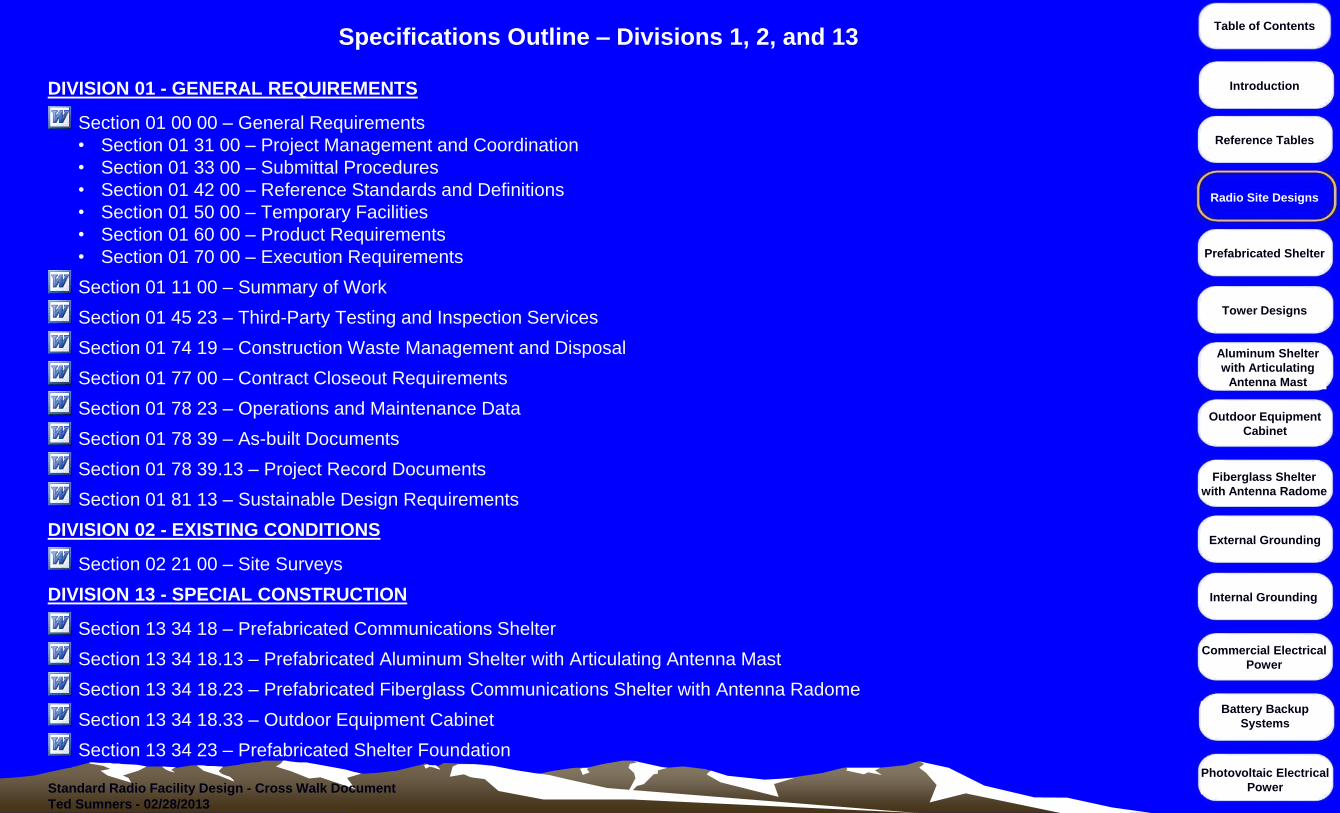
DIVISION 01 - GENERAL REQUIREMENTS
Section 01 00 00 – General Requirements
• Section 01 31 00 – Project Management and Coordination
• Section 01 33 00 – Submittal Procedures
• Section 01 42 00 – Reference Standards and Definitions
• Section 01 50 00 – Temporary Facilities
• Section 01 60 00 – Product Requirements
• Section 01 70 00 – Execution Requirements
Section 01 11 00 – Summary of Work
Section 01 45 23 – Third-Party Testing and Inspection Services
Section 01 74 19 – Construction Waste Management and Disposal
Section 01 77 00 – Contract Closeout Requirements
Section 01 78 23 – Operations and Maintenance Data
Section 01 78 39 – As-built Documents
Section 01 78 39.13 – Project Record Documents
Section 01 81 13 – Sustainable Design Requirements
DIVISION 02 - EXISTING CONDITIONS
Section 02 21 00 – Site Surveys
DIVISION 13 - SPECIAL CONSTRUCTION
Section 13 34 18 – Prefabricated Communications Shelter
Section 13 34 18.13 – Prefabricated Aluminum Shelter with Articulating Antenna Mast
Section 13 34 18.23 – Prefabricated Fiberglass Communications Shelter with Antenna Radome
Section 13 34 18.33 – Outdoor Equipment Cabinet
Section 13 34 23 – Prefabricated Shelter Foundation
Specifications Outline – Divisions 1, 2, and 13
Radio Site Designs

Standard Radio Facility Design - Cross Walk Document
Ted Sumners - 02/28/2013
Table of Contents
Introduction
Reference Tables
Radio Site Designs
Prefabricated Shelter
Tower Designs
Aluminum Shelter
with Articulating
Antenna Mast
Outdoor Equipment
Cabinet
Fiberglass Shelter
with Antenna Radome
External Grounding
Commercial Electrical
Power
Internal Grounding
Battery Backup
Systems
Photovoltaic Electrical
Power
DIVISION 26 - ELECTRICAL
Section 26 05 00 – Basic Electrical Materials and Methods
Section 26 21 13 – Low-voltage Electrical Service Entrance
Section 26 24 16 – Panel boards
Section 26 27 13 – Electricity Metering
Section 26 31 00 – Photovoltaic Collectors
Section 26 33 00 – Battery Systems
DIVISION 27 - COMMUNICATIONS
Section 27 05 10 – Cabling Requirements-Cable Trays-Ladders and Racks
Section 27 11 16 – Equipment Racks
Section 27 11 16.13 – Equipment Cabinet and Rack Installation
Section 27 11 16.23 – Equipment Installation in Racks and Cabinets
DIVISION 31 - EARTHWORK
Section 31 10 00 – Site Clearing
Section 31 20 00 – Earthwork-Grading
Section 31 23 16 – Excavation and Fill
Section 31 23 17 – Trenching
Section 31 23 23 – Utility Backfill Materials
DIVISION 32 - EXTERIOR IMPROVEMENTS
Section 32 31 13 – Chain-Link Fences and Gates
Specifications Outline - Divisions 26, 27, 31 and 32
Radio Site Designs
Standard Radio Facility Design - Cross Walk Document
Ted Sumners - 02/28/2013
Table of Contents
Introduction
Reference Tables
Radio Site Designs
Prefabricated Shelter
Tower Designs
Aluminum Shelter
with Articulating
Antenna Mast
Outdoor Equipment
Cabinet
Fiberglass Shelter
with Antenna Radome
External Grounding
Commercial Electrical
Power
Internal Grounding
Battery Backup
Systems
Photovoltaic Electrical
Power
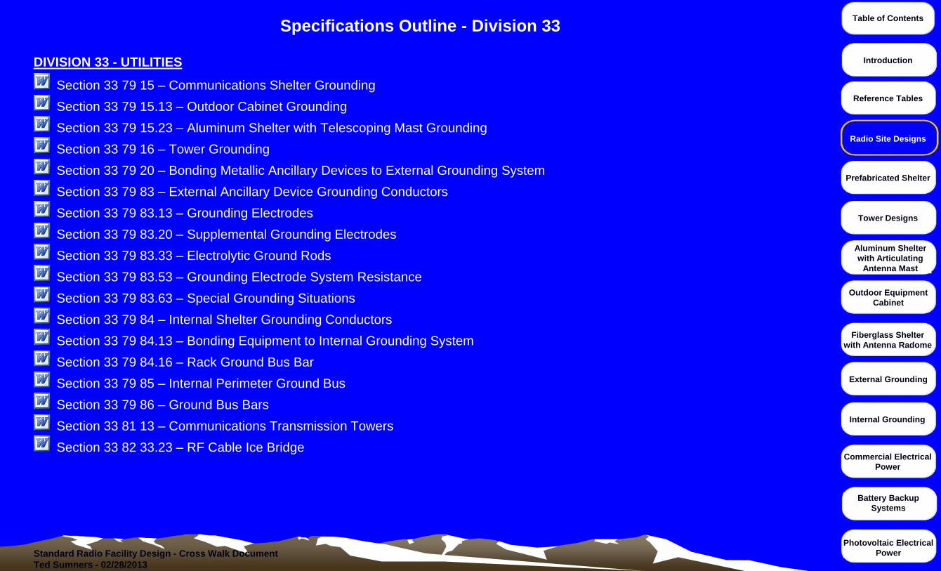
DIVISION 33 - UTILITIES
Section 33 79 15 – Communications Shelter Grounding
Section 33 79 15.13 – Outdoor Cabinet Grounding
Section 33 79 15.23 – Aluminum Shelter with Telescoping Mast Grounding
Section 33 79 16 – Tower Grounding
Section 33 79 20 – Bonding Metallic Ancillary Devices to External Grounding System
Section 33 79 83 – External Ancillary Device Grounding Conductors
Section 33 79 83.13 – Grounding Electrodes
Section 33 79 83.20 – Supplemental Grounding Electrodes
Section 33 79 83.33 – Electrolytic Ground Rods
Section 33 79 83.53 – Grounding Electrode System Resistance
Section 33 79 83.63 – Special Grounding Situations
Section 33 79 84 – Internal Shelter Grounding Conductors
Section 33 79 84.13 – Bonding Equipment to Internal Grounding System
Section 33 79 84.16 – Rack Ground Bus Bar
Section 33 79 85 – Internal Perimeter Ground Bus
Section 33 79 86 – Ground Bus Bars
Section 33 81 13 – Communications Transmission Towers
Section 33 82 33.23 – RF Cable Ice Bridge
Specifications Outline - Division 33
Radio Site Designs
Standard Radio Facility Design - Cross Walk Document
Ted Sumners - 02/28/2013
Table of Contents
Introduction
Reference Tables
Radio Site Designs
Prefabricated Shelter
Tower Designs
Aluminum Shelter
with Articulating
Antenna Mast
Outdoor Equipment
Cabinet
Fiberglass Shelter
with Antenna Radome
External Grounding
Commercial Electrical
Power
Internal Grounding
Battery Backup
Systems
Photovoltaic Electrical
Power
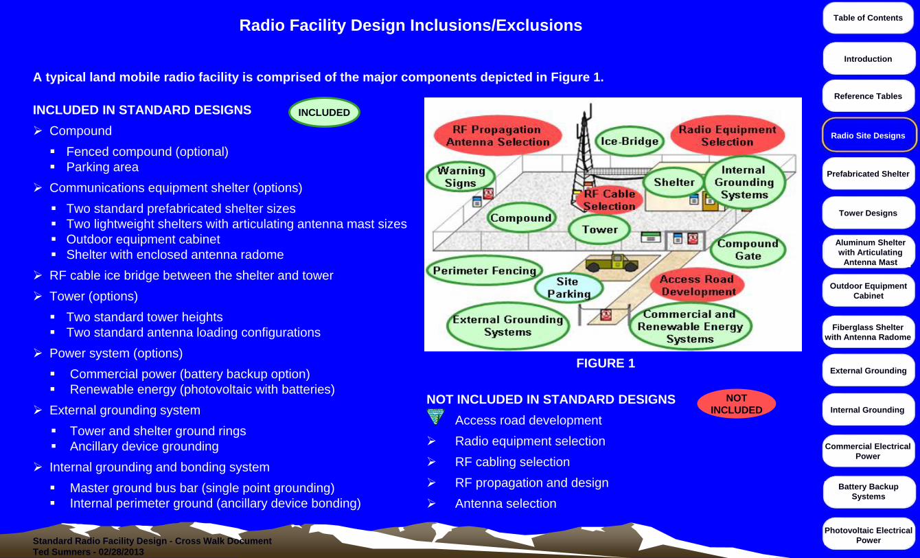
A typical land mobile radio facility is comprised of the major components depicted in Figure 1.
INCLUDED IN STANDARD DESIGNS
Compound
Fenced compound (optional)
Parking area
Communications equipment shelter (options)
Two standard prefabricated shelter sizes
Two lightweight shelters with articulating antenna mast sizes
Outdoor equipment cabinet
Shelter with enclosed antenna radome
RF cable ice bridge between the shelter and tower
Tower (options)
Two standard tower heights
Two standard antenna loading configurations
Power system (options)
Commercial power (battery backup option)
Renewable energy (photovoltaic with batteries)
External grounding system
Tower and shelter ground rings
Ancillary device grounding
Internal grounding and bonding system
Master ground bus bar (single point grounding)
Internal perimeter ground (ancillary device bonding)
NOT INCLUDED IN STANDARD DESIGNS
Access road development
Radio equipment selection
RF cabling selection
RF propagation and design
Antenna selection
INCLUDED
NOT
INCLUDED
FIGURE 1
Radio Facility Design Inclusions/Exclusions
Radio Site Designs

Standard Radio Facility Design - Cross Walk Document
Ted Sumners - 02/28/2013
Table of Contents
Introduction
Reference Tables
Radio Site Designs
Prefabricated Shelter
Tower Designs
Aluminum Shelter
with Articulating
Antenna Mast
Outdoor Equipment
Cabinet
Fiberglass Shelter
with Antenna Radome
External Grounding
Commercial Electrical
Power
Internal Grounding
Battery Backup
Systems
Photovoltaic Electrical
Power
Design drawing packages and specification workbooks have been assembled for each typical radio facility type. The drawing files are in
Adobe PDF format and the specification workbooks are in MS Word format.
Click on the ADOBE icon to view the drawing file.
Click on the DOLLAR icon to view budgetary pricing.
Click on the WORD icon to view the specification workbook.
The specification workbooks contain all specifications created for each facility type.
All site design variables are contained in the Summary of Work Section in each workbook.
Design Drawings and Workbooks
8-foot wide, 12-foot long, Prefabricated Shelter with 40-foot to 60-foot tower
8-foot wide, 16-foot long, Prefabricated Shelter with 60-foot to 80-foot tower
Fiberglass Shelter with Antenna Radome
8-foot wide, 12-foot long, Lightweight Aluminum Shelter with Articulating Antenna Mast
8-foot wide, 16-foot long, Lightweight Aluminum Shelter with Articulating Antenna Mast
Lightweight Aluminum Cabinet with Articulating Antenna Mast
Outdoor Equipment Cabinet with Antenna Pipe Mast
Tower Design Drawings
Typical tower designs are not intended to be used for construction of a new radio facility
The typical towers are designed with maximum antenna loading based on presumptive soils and not actual soil
conditions
Radio Site Designs
Standard Radio Facility Design - Cross Walk Document
Ted Sumners - 02/28/2013
Table of Contents
Introduction
Reference Tables
Radio Site Designs
Prefabricated Shelter
Tower Designs
Aluminum Shelter
with Articulating
Antenna Mast
Outdoor Equipment
Cabinet
Fiberglass Shelter
with Antenna Radome
External Grounding
Commercial Electrical
Power
Internal Grounding
Battery Backup
Systems
Photovoltaic Electrical
Power
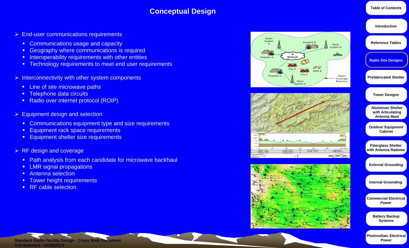
End-user communications requirements
Communications usage and capacity
Geography where communications is required
Interoperability requirements with other entities
Technology requirements to meet end user requirements
Interconnectivity with other system components
Line of site microwave paths
Telephone data circuits
Radio over internet protocol (ROIP)
Equipment design and selection
Communications equipment type and size requirements
Equipment rack space requirements
Equipment shelter size requirements
RF design and coverage
Path analysis from each candidate for microwave backhaul
LMR signal propagations
Antenna selection
Tower height requirements
RF cable selection
Conceptual Design
Radio Site Designs

Standard Radio Facility Design - Cross Walk Document
Ted Sumners - 02/28/2013
Table of Contents
Introduction
Reference Tables
Radio Site Designs
Prefabricated Shelter
Tower Designs
Aluminum Shelter
with Articulating
Antenna Mast
Outdoor Equipment
Cabinet
Fiberglass Shelter
with Antenna Radome
External Grounding
Commercial Electrical
Power
Internal Grounding
Battery Backup
Systems
Photovoltaic Electrical
Power
FACILITY CANDIDATE SEARCH
Radio facility candidates should meet RF coverage requirements for two-way communications and microwave backhaul
pathways.
Prior to construction of a new radio facility, search for the availability of existing radio facilities for collocation. Collocation
agreements may include the following documentation:
Memorandum of Understanding (MOU)
Memorandum of Agreement (MOA)
Leasing, right-of-way, and easements
The accessibility of proposed radio facility locations must be investigated to determine feasibility to transport shelters , towers,
and associated foundations to the location. Improvements to the access route may be required to facilitate delivery of
equipment and for continuous year round maintenance.
Helicopter-access only locations should be avoided whenever possible because of increased cost for construction and
maintenance
Available space and topography of the proposed radio facility location must be considered for placement of the shelter, tower,
and other components.
Availability and distance of existing commercial power and local private telephone utilities to the proposed radio facility location
must be considered.
Regulatory compliance and due diligence at the proposed radio facility location must include the following:
Radio frequency authorization (RFA)
Local jurisdiction permitting and zoning;
National Environmental Policy Act (NEPA)
State Historic Preservation Office (SHPO)
Tower Construction Notification System (TCNS)
Federal Aviation Administration (FAA)
Radio Facility Candidate Search
Radio Site Designs

Standard Radio Facility Design - Cross Walk Document
Ted Sumners - 02/28/2013
Table of Contents
Introduction
Reference Tables
Radio Site Designs
Prefabricated Shelter
Tower Designs
Aluminum Shelter
with Articulating
Antenna Mast
Outdoor Equipment
Cabinet
Fiberglass Shelter
with Antenna Radome
External Grounding
Commercial Electrical
Power
Internal Grounding
Battery Backup
Systems
Photovoltaic Electrical
Power
Preliminary Civil Design of a radio facility must include the following:
Site Layout Plan
The site layout plan shows the proposed location of major site components including the shelter, tower, existing and
proposed utility routes, photovoltaic array, generator, and fuel storage tanks;
The tower must be designed a minimum of 10 feet from the shelter and ideally 30 feet to decrease the amount of lighting
energy diverted into the shelter; and
The shelter access door should be oriented to the south at locations where snow and ice may accumulate.
Civil Survey
Civil surveys provide a legal description of the property and a detailed drawing (map) including the location of existing
markers, boundaries, easements, encroachments, utilities, roads, and other terrain features.
Topographical Land Survey
Mapping to indicate the elevations and contours of the land; and shows both natural and artificial features (e.g. streams
buildings, quarries, fences, roads, woodlands, etc.).
Utility Locates and Staking
Utility location is the process of identifying and labeling public utility mains located underground. These mains may include
lines for telephones, electricity distribution, natural gas, cable television, fiber optics, traffic lights, street lights, storm drains,
water mains, and wastewater pipes. In some locations, major oil and gas pipelines, national defense communication lines,
mass transit, rail, and road tunnels also compete for space underground.
Geotechnical Survey (Motorola R56, Section 2.4.6 – Geotechnical Considerations)
A geotechnical survey includes a detailed investigation of the soil to determine the soil strength, composition, water content,
and other important soil characteristics.
Soil Resistivity Measurements (Motorola R56, Appendix B – Soil Resistivity Measurements)
Soil resistivity directly affects the design of a grounding (earthing) electrode system. Prior to the design and installation of a
new radio facility, the proposed location must be tested to determine the soil's resistivity.
Preliminary Civil Design
Radio Site Designs

Standard Radio Facility Design - Cross Walk Document
Ted Sumners - 02/28/2013
Table of Contents
Introduction
Reference Tables
Radio Site Designs
Prefabricated Shelter
Tower Designs
Aluminum Shelter
with Articulating
Antenna Mast
Outdoor Equipment
Cabinet
Fiberglass Shelter
with Antenna Radome
External Grounding
Commercial Electrical
Power
Internal Grounding
Battery Backup
Systems
Photovoltaic Electrical
Power
The preliminary design for the communications equipment shelter must consider the following:
The shelter must be sized to accommodate the planned and future radio equipment and support apparatus as well as collocation of
cooperator equipment.
Accessibility to the radio facility location must be considered when selecting the size, type, and weight of the shelter.
Helicopter access only facilities can increase shelter delivery costs.
Facilities with narrow or steep access routes can make delivery of large shelters prohibitive and increase delivery costs.
Shelter structure, exterior walls, and roof must be designed and suited for the environment.
Shelter floor loading design strength must accommodate the weight of the radio equipment racks and batteries.
Availability of commercial power must be considered to provide proper electrical specifications to the shelter vendor.
Photovoltaic-powered facilities may not require the typical AC power panel, lighting, and electrical outlets.
Heat generation by the equipment installed inside the shelter and average temperatures at the radio facility must be considered to
provide information to the shelter vendor for designing heating ventilation and air conditioning (HVAC) equipment.
When designing the initial layout of the facility, the shelter entrance door should be designed to face south whenever possible.
Installing the access door to the south provides protection from prevailing winds from the north, minimizes snow drifts near the door,
and provides adequate sun during the spring to melt away accumulated snow and ice.
Second option would be for the entrance door to face west.
Third option would be for the entrance door to face east.
Where the only option is to install the shelter door facing north, the facility design should provide the following protection
measures:
• Install a 7-foot tall chain-link fence, equipped with nonmetallic slats, located 6 to 8 feet to the north of the shelter. This will
provide protection from northern wind exposure and provide protection from drifting snow; and
• Install a 42-inch wide entry way cover (awning) over the shelter access door to provide protection to the access door and steps
from falling snow.
Preliminary Communications Equipment Shelter Design
Radio Site Designs

Standard Radio Facility Design - Cross Walk Document
Ted Sumners - 02/28/2013
Table of Contents
Introduction
Reference Tables
Radio Site Designs
Prefabricated Shelter
Tower Designs
Aluminum Shelter
with Articulating
Antenna Mast
Outdoor Equipment
Cabinet
Fiberglass Shelter
with Antenna Radome
External Grounding
Commercial Electrical
Power
Internal Grounding
Battery Backup
Systems
Photovoltaic Electrical
Power
Preliminary design of a radio facility with a communications tower must evaluate the following:
FAA Obstruction Evaluation (IAW - FAA Order 8260.19E, Appendix 3) and 14 CFR 77.
The obstruction evaluation is required when the proposed tower height exceeds 200 feet in accordance with 14 CFR 77.9 (a)
When the tower exceeds an imaginary surface extending outward and upward at any of the slopes detailed in 14 CFR 77.9 (b)
Any highway, railroad, or other traverse way for mobile objects, of a height which, if adjusted upward 17 feet for an Interstate
Highway that is part of the National System of Military and Interstate Highways where overcrossings are designed for a minimum of
17 feet vertical distance, 15 feet for any other public roadway, 10 feet or the height of the highest mobile object that would normally
traverse the road, whichever is greater, for a private road, 23 feet for a railroad, and for a waterway or any other traverse way not
previously mentioned, an amount equal to the height of the highest mobile object that would normally traverse it, would exceed a
standard of paragraph (a) or (b) of this section in accordance with 14 CFR 77.9 (c)
Any construction or alteration on any of the following airports and heliports:
A public use airport listed in the Airport/Facility Directory, Alaska Supplement, or Pacific Chart Supplement of the US.
Government Flight Information Publications
A military airport under construction, or an airport under construction that will be available for public use
An airport operated by a Federal agency or the DOD
An airport or heliport with at least one FAA-approved instrument approach procedure
Notice for construction or alteration does not need to be filed for the following:
Any object that will be shielded by existing structures of a permanent and substantial nature or by natural terrain or topographic
features of equal or greater height, and will be located in the congested area of a city, town, or settlement where the shielded
structure will not adversely affect safety in air navigation;
Any air navigation facility, airport visual approach or landing aid, aircraft arresting device, or meteorological device meeting FAA-
approved siting criteria or an appropriate military service siting criteria on military airports, the location and height of which are
fixed by its functional purpose;
Any construction or alteration for which notice is required by any other FAA regulation; or
Any antenna structure of 20 feet or less in height, except one that would increase the height of another antenna structure.
Preliminary Tower Design – Obstruction Evaluation
Radio Site Designs
Standard Radio Facility Design - Cross Walk Document
Ted Sumners - 02/28/2013
Table of Contents
Introduction
Reference Tables
Radio Site Designs
Prefabricated Shelter
Tower Designs
Aluminum Shelter
with Articulating
Antenna Mast
Outdoor Equipment
Cabinet
Fiberglass Shelter
with Antenna Radome
External Grounding
Commercial Electrical
Power
Internal Grounding
Battery Backup
Systems
Photovoltaic Electrical
Power
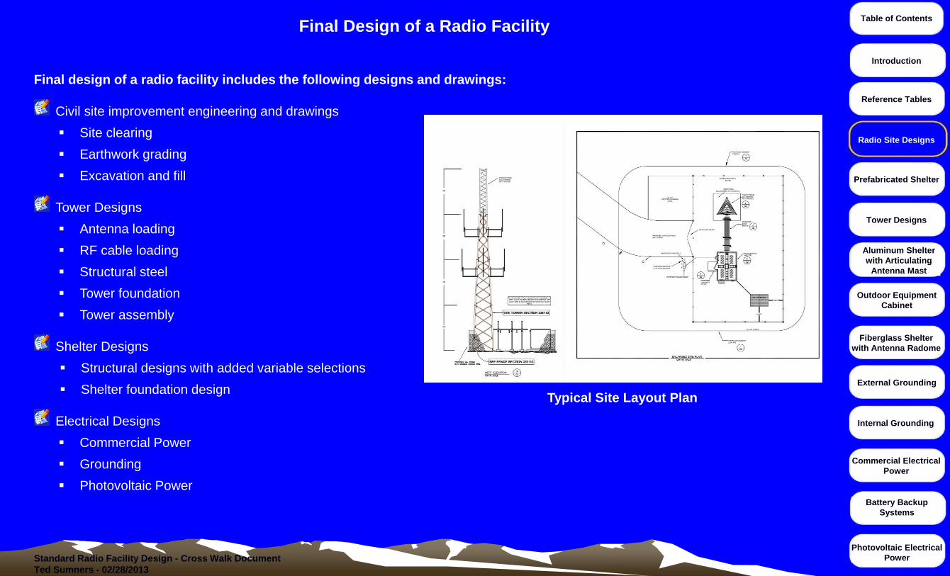
Final design of a radio facility includes the following designs and drawings:
Civil site improvement engineering and drawings
Site clearing
Earthwork grading
Excavation and fill
Tower Designs
Antenna loading
RF cable loading
Structural steel
Tower foundation
Tower assembly
Shelter Designs
Structural designs with added variable selections
Shelter foundation design
Electrical Designs
Commercial Power
Grounding
Photovoltaic Power
Final Design of a Radio Facility
Typical Site Layout Plan
Radio Site Designs