U.S. Department of Energy Collegiate Wind Competition 2018 ... 2018 Rules and Requirements...•...
47
iii This report is available at no cost from the National Renewable Energy Laboratory at www.nrel.gov/publications. Revision 2: 8/28/2017
Transcript of U.S. Department of Energy Collegiate Wind Competition 2018 ... 2018 Rules and Requirements...•...

iii
This report is available at no cost from the National Renewable Energy Laboratory at www.nrel.gov/publications.
Revision 2: 8/28/2017
iv
This report is available at no cost from the National Renewable Energy Laboratory at www.nrel.gov/publications.
Preface The U.S. Department of Energy Collegiate Wind Competition 2018 will be governed and adjudicated by this manual, which is intended to establish fair contest rules and requirements. In the case of a discrepancy with other competition materials or communication, this document takes precedence. The organizers reserve the right to change contest criteria, rules, and measurable outcomes as needed.
In addition, teams are encouraged to bring to our attention rules that are unclear, misguided, or in need of improvement. The organizers will seriously consider suggestions that are feasible and within our constraints and are intended to improve the competition, its rules, measurable outcomes, fairness, or precision.

v
This report is available at no cost from the National Renewable Energy Laboratory at www.nrel.gov/publications.
Table of Contents Revision History .......................................................................................................................................... 1 1 Introduction ........................................................................................................................................... 2
1.1 Background ................................................................................................................................... 2 1.2 Roles and Responsibilities ............................................................................................................ 3 1.3 Safety and Conduct ....................................................................................................................... 5 1.4 Dispute Resolution ........................................................................................................................ 6
2 Competition, Contests, Products, and Awards ................................................................................. 7 3 Overview of Products ........................................................................................................................... 9
3.1 Products in Advance of Competition Event .................................................................................. 9 3.2 Products at the Competition Event ................................................................................................ 9
4 Written Report: Business and Design .............................................................................................. 10 4.1 Cover Sheet ................................................................................................................................. 10 4.2 Executive Summary .................................................................................................................... 10 4.3 Business Plan............................................................................................................................... 11 4.4 Technical Design ......................................................................................................................... 12
5 Presentations: Business and Design ............................................................................................... 13 5.1 Private Presentation ..................................................................................................................... 13 5.2 Public Pitch ................................................................................................................................. 13
6 Test Turbine Design and Evaluation ................................................................................................ 15 6.1 Turbine and Load Design Requirements ..................................................................................... 16 6.2 Testing Procedure ........................................................................................................................ 21
7 Siting Challenge.................................................................................................................................. 24 7.1 Part 1: Research and Develop a Plan for a 100-MW Wind Farm in the Team’s Home State ..... 24 7.2 Part 2: Design a Wind Farm During the Competition ................................................................. 25
Glossary ..................................................................................................................................................... 27 Appendix A. Timeline and Schedule ....................................................................................................... 28
Competition Timeline ........................................................................................................................... 28 Event Schedule ..................................................................................................................................... 28
Appendix B. Rubrics ................................................................................................................................. 30 Products ................................................................................................................................................ 30 Written Report ...................................................................................................................................... 30 Private Presentation .............................................................................................................................. 31 Public Pitch........................................................................................................................................... 31 Siting Challenge ................................................................................................................................... 32 Turbine Performance Testing ............................................................................................................... 33
Appendix C. Communications and Business Operations .................................................................... 38 External Communications .................................................................................................................... 38 Internal Communications ..................................................................................................................... 38 Branding ............................................................................................................................................... 38 Confidentiality and Intellectual Property ............................................................................................. 39 Judging and Scoring ............................................................................................................................. 39
Appendix D. Product Submission Instructions ..................................................................................... 41 Submission Locations ........................................................................................................................... 41 PDF Requirements ............................................................................................................................... 41 Audio Visual Presentation Requirements ............................................................................................. 41 Electronic File-Naming Instructions .................................................................................................... 41
Appendix E. Sample Safety and Technical Inspection ......................................................................... 43

vi
This report is available at no cost from the National Renewable Energy Laboratory at www.nrel.gov/publications.
List of Figures Figure 1. Collegiate Wind Competition wind tunnel basic configuration ........................................... 15 Figure 2. Allowable turbine volume ........................................................................................................ 16 Figure 3. Base flange dimensions for turbine attachment to tunnel (dimensions in cm) ................. 17 Figure 4. Load, turbine, storage element, and point of common coupling arrangement .................. 18 Figure 5. Competition-provided ultracapacitor storage element ......................................................... 19 Figure 6. Team-provided connection to the manual shutdown interface ........................................... 20 Figure 7. Competition-provided connector for manual shutdown interface ...................................... 20 Figure B-1. Score weighting based on power ratio for control of rated power task .......................... 34 Figure B-2. Score weighting based on rpm ratio for control of rated rotor speed task .................... 35 Figure B-3. Score weighting based on voltage for durability task....................................................... 36
List of Tables Table 1. Roles and Responsibilities .......................................................................................................... 3 Table 2. Contests and Products Overview ............................................................................................... 7 Table A-1. 2018 Competition Timeline and Related Activities.............................................................. 28 Table A-2. Competition Event Schedule ................................................................................................. 29 Table B-1. Scoring Summary for the Competition Products (1,000 Points Total) .............................. 30 Table B-2. Scoring Rubric for the Written Report (250 Points Total)*, ** ............................................. 30 Table B-3. Scoring Rubric for the Private Presentation (100 Points Total) ......................................... 31 Table B-4. Scoring Rubric for the Public Pitch (125 Points Total)*, ** ................................................. 31 Table B-5. Siting Challenge Rubric – Part 1: Proposed Wind Farm Plans (100 Points Total) ........... 32 Table B-6. Siting Challenge Rubric – Part 2: On-Site Design Challenge (100 Points Total) ............. 32 Table B-7. Scoring Rubric for Turbine Performance Testing (325 Points Total) ................................ 33 Table B-8. Weighting for the Power Curve Performance Task ............................................................. 33 Table D-1. Team Names and Abbreviations ........................................................................................... 42 Table D-2. Product Names and Abbreviations ....................................................................................... 42

1
This report is available at no cost from the National Renewable Energy Laboratory at www.nrel.gov/publications.
Revision History This document is a revision of the original. Specific changes are detailed below.
• Version 1: Original document issued 7/27/17.
• Version 2: Issued 8/28/17 o Adjusted requirements relating to financial analysis in Section 4.3
o Added maximum demand specification for load during durability testing in Section 6.2.4 and added maximum voltage limit for capacitive storage element in Section 6.1. Consequences for exceeding the capacitor voltage limit were added to Appendix B.
o Clarified which sites can be used for part 1 of the siting challenge in Section 7.1

2
This report is available at no cost from the National Renewable Energy Laboratory at www.nrel.gov/publications.
1 Introduction 1.1 Background According to the U.S. Department of Energy’s (DOE’s) Wind Vision report, wind generation could double by 2020 and double again by 2030.1 As more wind energy is incorporated into the United States’ power generation mix, qualified workers are needed to fill related jobs at all levels.
To help facilitate this process, DOE and the National Renewable Energy Laboratory (NREL) created the Collegiate Wind Competition in 2014 (hereafter referred to as the Collegiate Wind Competition or competition). The competition directly aligns with DOE’s overall goals: to create and sustain American leadership in the transition to a global clean energy economy. Its vision is a strong and prosperous America powered by clean, affordable and secure energy.2 Specifically, the competition’s objective is to prepare students from multiple disciplines to enter the wind energy workforce by providing real-world technology experience. Positions in the workforce that require development include researchers, scientists, engineers, educators, project managers, business and sales forces, and many others. Wind-energy-specific advanced degrees are not required for many of these jobs, but having wind-related experience is considered to be highly valuable.3
Each year the competition identifies a new challenge and set of activities to address real world research questions, thus demonstrating skills students will need working in the wind or wider energy industry. The Collegiate Wind Competition 2018 challenge is to:
Research and design a turbine for a grid scenario with a high contribution of renewables and be able to operate in an islanded mode.
Specifically, competition participants will need to create:
• A market-research-supported business plan and conceptual-level technical design development of a marketable wind power system.
• An effective mechanical, electrical, and aerodynamic wind turbine and load design that is safe and reliable for testing in an on-site wind tunnel.
• An electrical control system that can maintain a constant voltage into a competition-provided variable-resistance load during the durability portion of the turbine testing, utilizing a competition-provided storage element to balance source and load energy.
The competition does not prescribe a power system market or wind regime.
1 Source: http://www.energy.gov/eere/wind/maps/wind-vision; accessed 7/21/17. 2 Source: https://energy.gov/eere/about-us/mission; accessed 7/21/17 3 Source: Leventhal, M. and Tegen, S. A National Skills Assessment of the U.S. Wind Industry in 2012. NREL Technical Report TP-7A30-57512. June 2013.
3
This report is available at no cost from the National Renewable Energy Laboratory at www.nrel.gov/publications.
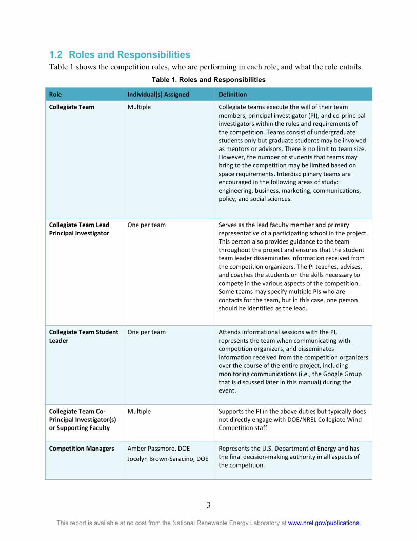
1.2 Roles and Responsibilities Table 1 shows the competition roles, who are performing in each role, and what the role entails.
Table 1. Roles and Responsibilities
Role Individual(s) Assigned Definition
Collegiate Team Multiple Collegiate teams execute the will of their team members, principal investigator (PI), and co-principal investigators within the rules and requirements of the competition. Teams consist of undergraduate students only but graduate students may be involved as mentors or advisors. There is no limit to team size. However, the number of students that teams may bring to the competition may be limited based on space requirements. Interdisciplinary teams are encouraged in the following areas of study: engineering, business, marketing, communications, policy, and social sciences.
Collegiate Team Lead Principal Investigator
One per team Serves as the lead faculty member and primary representative of a participating school in the project. This person also provides guidance to the team throughout the project and ensures that the student team leader disseminates information received from the competition organizers. The PI teaches, advises, and coaches the students on the skills necessary to compete in the various aspects of the competition. Some teams may specify multiple PIs who are contacts for the team, but in this case, one person should be identified as the lead.
Collegiate Team Student Leader
One per team Attends informational sessions with the PI, represents the team when communicating with competition organizers, and disseminates information received from the competition organizers over the course of the entire project, including monitoring communications (i.e., the Google Group that is discussed later in this manual) during the event.
Collegiate Team Co-Principal Investigator(s) or Supporting Faculty
Multiple Supports the PI in the above duties but typically does not directly engage with DOE/NREL Collegiate Wind Competition staff.
Competition Managers Amber Passmore, DOE Jocelyn Brown-Saracino, DOE
Represents the U.S. Department of Energy and has the final decision-making authority in all aspects of the competition.

4
This report is available at no cost from the National Renewable Energy Laboratory at www.nrel.gov/publications.
Role Individual(s) Assigned Definition
Competition Operations Manager
Elise DeGeorge, NREL
Leads correspondence with the collegiate teams regarding contracts, contest questions, and team expectations. During the competition, the operations manager is the primary point of contact for questions related to engagement with the judges, logistics, individual competition contests, and protocol. Tasks include developing team schedules and coordinating/collating scores and team feedback from the contests in time for the awards ceremony; and supporting the testing team, collegiate teams, judges, competition manager, and head rules official. Reports to the competition managers.
Logistics Point of Contact
Bethany Straw, NREL Coordinates competition logistics including registration, lodging, the schedule, and related topics.
Competition Safety Point of Contact
Ian Baring-Gould, NREL Point of contact for questions or issues related to safety.
Rules Panel
See definition Rules panel members, a subset of the competition organizers and/or contest judges, are solely authorized to interpret the rules. If there is any doubt or ambiguity as to the wording or intent of these rules, the decision of the rules panel shall prevail.
Head Rules Official and Turbine Safety Official
Jason Roadman, NREL The head rules official and chair of the rules panel. The only official authorized to write and modify the rules. This individual reports to the competition manager. The turbine safety official makes the final decision of whether a turbine can be tested or not in the tunnel due to safety concerns.
Communications and Outreach Point of Contact
Devan Willemsen, DOE Jamie Wiebe, NREL
Coordinates all aspects of media representation, website management, publications, signage, and outreach.
Core Competition Staff Mike Arquin, KidWind Lee Jay Fingersh, NREL Heidi Tinnesand, NREL Suzanne Tegen, NREL Corrie Christol, NREL Plus All Names Listed Above
Performs all duties to ensure a safe, effectively communicated, and fair competition. The competition organizers, including the competition manager and operations manager, will work to ensure a seamless event.
Contest Judges To be announced prior to the competition
Conduct and evaluate each individual contest at the competition.

5
This report is available at no cost from the National Renewable Energy Laboratory at www.nrel.gov/publications.
1.3 Safety and Conduct The competition is a forum for students with an interest in wind energy to showcase their innovative ideas and demonstrate their knowledge. The event is designed to be safe, fair, and competitive, as well as be a fun learning experience and a professional growth opportunity. Each team is responsible for the safety of its operations in accordance with the subcontract agreement. Each team member shall work in a safe manner at all times during the competition. Participants are expected to conduct themselves in the spirit of the competition by being team players both within their own teams and amongst competitor teams.
Teams must follow Occupational Safety and Health Administration rules for safety equipment based on expected activities (see NREL/university subcontract, Appendix B Clause 8: Worker Safety and Health Requirements, for more information). Organizers may issue a stop work order at any time during the project if a hazardous condition is identified.
All team members must wear appropriate personal protective equipment when working on, testing, and operating wind turbines. Teams are expected to bring the following appropriate protective equipment for use during wind tunnel testing and other potentially hazardous activities at the competition:
• Safety glasses
• Hard hats
• Steel-toe boots if expecting to handle heavy loads
• Electrical personal protective equipment if electrical voltage demands it
• Hearing protection for use in areas that are in close proximity to the wind tunnel during operation.
Each team is responsible for the transport of its wind turbine and all necessary tools and equipment as well as for any damage to or loss of such items. Shipping information will be provided before the competition event.
There will be electrical outlets available in the bull pen area to allow students to operate tools, test equipment, or computers.
As part of DOE’s and NREL’s culture, renewable energy and sustainability go hand in hand. It is a common public perception as well. As a result, the competition is about renewable wind energy, and we expect that participants will embrace and showcase sustainability where possible during all aspects of the event (e.g., reducing waste in packaging for shipping, re-using packaging materials that were used in transporting items to the competition, and eliminating the use of non-recyclable materials such as foam packing peanuts). In addition, we encourage team members to engage in common sustainable activities such as recycling paper and beverage containers. Team creativity to support this mission is encouraged.

6
This report is available at no cost from the National Renewable Energy Laboratory at www.nrel.gov/publications.
1.4 Dispute Resolution Disputes are a serious matter and will be treated as such. Disputes must:
• Be submitted to the competition operations manager by the collegiate team PI.
• Be submitted via email and be accompanied by an in person notification of the email
• Include a clear description of the action being protested, referencing the appropriate section of this rules document.
Once submitted, the competition operations manager will meet with the head rules judge and initiate an internal review of the dispute. Disputes will be discussed amongst at least three judges and/or competition organizers who will gather appropriate information through interviews or other means and a final ruling will be issued. If it is concluded that the issue has a broader impact on the entire competition, the head rules official will consult with all necessary members of the DOE/NREL organizing team to determine next steps.
If the head rules official makes a decision that may directly or indirectly affect the strategies of some or all of the teams, the decision will be recorded in the “Decisions on the Rules” section of the Google Group site (discussed further in Appendix C) within 24 hours. If the dispute is being handled during the competition event, an announcement at the next major address to teams (opening or closing remarks for the day, lunch, and so on) may be substituted for the Google Group post.
In all cases, the head rules official has the final say in all disputes.

7
This report is available at no cost from the National Renewable Energy Laboratory at www.nrel.gov/publications.
2 Competition, Contests, Products, and Awards The Collegiate Wind Competition 2018 consists of all of the aspects and activities leading up to, during, and following the event. It includes the subcontract project agreement between the competitively selected collegiate teams and NREL, as well as the contests, products, and event.
At the event, teams compete in four contests. Products receive points toward winning a contest. An overview of which product contributes to the scoring of each of the contests is in Table 2. How many points a product contributes to the overall score is covered in Appendix B.
Table 2. Contests and Products Overview
Products
Competition Contests
Written Report
Private Presentation
Public Pitch
Siting Poster
On-Site Siting
Design
Turbine and Load
Business Plan * - - -
Technical Design ** - - -
Turbine Testing - - - - -
Siting Challenge - - - - * The business plan needs to be minimally included in the private technical design presentation to provide context to design judges.
**The technical design of the test turbine needs to be minimally included in the public pitch to provide context to the business plan judges as to the rationale behind the size and distinguishing features of the turbine being tested in the Collegiate Wind Competition wind tunnel.
This manual is arranged by product. Products include a single written report, one private on-site oral presentation, one public pitch, a siting poster, the results of the on-site siting design challenge, and a wind turbine and load combination for testing in an on-site wind tunnel.
While teams work on these products, principal investigators, co-principal investigators, graduate student advisors, and members of industry secured by each team for support can provide feedback about the team’s design so the students can identify fatal flaws, prove technical rigor, or demonstrate certification of concept. However, only student team members may take an active role in any competition event.
Awards will be provided for, but not necessarily limited to, the following: • Overall winner—the team that earns the highest combined score.
• Second place winner—the team that earns the second highest combined score.
• Third place winner—the team that earns the third highest combined score.
• Business plan contest winner—the team that earns the highest combined score from all business plan products.

8
This report is available at no cost from the National Renewable Energy Laboratory at www.nrel.gov/publications.
• Technical design contest winner—the team that earns the highest combined score from all technical design products.
• Turbine testing contest winner—the team that earns the highest combined score from all of the turbine tasks.
• Siting contest winner—the team that earns the highest combined score for all elements of the wind farm siting challenge.
• People’s choice award - the team that receives the most public support during the event, as measured via social platforms.4
4 Specific details regarding the People’s Choice Award will be announced prior to the 2018 Collegiate Wind Competition.

9
This report is available at no cost from the National Renewable Energy Laboratory at www.nrel.gov/publications.
3 Overview of Products This section gives an overview of when products should be delivered. Refer to each product section and Appendix D for specific deadlines, for format requirements, and submission instructions. Information on scoring and penalties can be found in Appendix B.
3.1 Products in Advance of Competition Event The written report must be completed and submitted prior to the competition so that the judges can review it prior to arriving on-site. See Section 4 for deadline information. See Appendix D for information on submission.
3.2 Products at the Competition Event At the competition event, judges will:
• Verify that the wind turbine is accurately represented in the report
• Conduct a safety and compliance inspection of the turbine and load prior to testing. See Appendix E for a draft version of the sheet that will be used for this review.
• Ask the team members any clarifying questions that arose during the evaluation of the product(s).
Teams must bring their:
• Private presentation
• Public pitch presentation
• Siting poster
• Turbine
• Load system
10
This report is available at no cost from the National Renewable Energy Laboratory at www.nrel.gov/publications.
4 Written Report: Business and Design Each team must compile a single written report covering the business plan and technical design, that is due on April 23, 2018, by 11:59 p.m. Mountain Daylight Time.
The following format requirements apply to the written report:
• Length must not exceed 30 pages (including the cover and appendices); pages submitted beyond this limit will not be reviewed.
• Pages should be 8.5 x 11 inches, paginated, single-sided, and with 1-inch margins at a minimum.
• Content should be at a minimum single-spaced.
• The body of the report must use at a minimum an 11-point font.
• Captions for figures and tables must be numbered for easy navigation.
• The final document must be packaged into a single, bookmarked PDF file (see Appendix D). Multiple contests are included in a single report to encourage integration and cohesiveness. Each individual section as outlined below should—where relevant—reference other sections. The written report is the primary means for a team to provide detailed information about its project to the judges, given that the judges have a limited opportunity at the competition event to evaluate the wind turbine design specifications and hear about how the market-research-supported business plan shaped the design. Cohesiveness of the report sections will be evaluated in the final score. At a minimum, the report must include the following sections:
• Cover sheet
• Executive summary
• Business plan
• Technical design Scoring criteria for the written report is provided in Appendix B, Table B-2. At the conclusion of the competition, team reports will be posted to the competition website for reference during future events.
4.1 Cover Sheet Teams should begin the report with a 1-page cover sheet that includes their affiliation and contact information. Indicate the team roles/hierarchy and approximately how many students, faculty, and others (e.g., sponsors, volunteers, and family members) are involved in the project.
4.2 Executive Summary The executive summary discusses components from all sections of the report and includes a short description of the team project (in approximately 300 words). The information in the executive summary is important to many communications-related aspects of the competition and should:
• Provide essential content for the organizers to use while developing various event materials (e.g., the website, event program, media kit, and signage).

11
This report is available at no cost from the National Renewable Energy Laboratory at www.nrel.gov/publications.
• Prepare teams to answer questions from visitors at the competition event.
• Help organizers and teams respond effectively to media inquiries. The executive summary must not exceed three pages (including figures). It is recommended to write this section last to best capture the distinct and unique factors of the written report.
4.3 Business Plan The business plan should be readable, concise, and interesting, focusing on all aspects of product development. It must, at a minimum, include the following:
• Business Overview. This section should include information about the product/company, such as its name, the business model and vision, and a concise overview of the product/company’s value proposition (e.g., financial, social, and/or environmental).
• Market Opportunity. This section should characterize the overall market opportunity and explain how the product/company will capture a portion of it. At a minimum, a definition of the problem or market gap should be included, along with a market opportunity forecast and potential solutions/competition analyses. This section should also provide a pricing strategy and customer value proposition analysis to support revenue forecasts. It is critical that each team performs substantial market analysis that contains direct outreach. Some specific questions this section may seek to answer include:
o What specific market needs does the product offering meet and what segments will the product compete in? How does the team’s particular turbine meet the needs and desires of the indicated target market?
o How will the company price its offering? How does this coincide with the value proposition from the customer’s perspective? How does the pricing compare to the competition? How do state, federal, or other incentives come into play?
o How will the proposed venture be capitalized?
• Management Team. This section should identify the roles and responsibilities of the company leadership and staff, including strategic advisors or a board of directors (if warranted).
• Development and Operations. This section should describe the development of the product, company, and associated activities. Conceptual-level product plans and specifications that are presented within the technical design section of the written report should be referenced. Some specific questions this section may seek to answer include:
o How will research and development be accomplished? What will be the company’s approach to manufacturing? How will the product be distributed? What partnerships will be leveraged? What are the significant risks and what is the approach to managing them?
o Are there technical constraints to implementation? Is the proposed concept buildable? This section is where the wind turbine’s technical design, system specifications, energy analysis results and discussion, and engineering narratives can be referenced. Teams should also include technical, social, and environmental impacts and/or opportunities here.

12
This report is available at no cost from the National Renewable Energy Laboratory at www.nrel.gov/publications.
o How do the development and operation efforts coincide with the design?
• Financial Analysis. This section should outline the financial potential of the product/company noting required capital, financing, and key assumptions (e.g., product marginal costs). Pro forma financial statements—such as the income statement, cash flow statement, and balance sheet—should be presented for the first year, demonstrating the path to solvency and outlining the product/company’s potential. Full pro formas are not required, however, it is recommended that higher level, more long-term, summaries be used in the business plan narrative to communicate the attractiveness of their company for investment.
4.4 Technical Design The technical design section of the written report explains the turbine concept development process from an engineering perspective. Teams must include conceptual design-level detail on their market turbine that is being presented in the teams’ business plan. The remainder of the design report should detail the complete design process as it relates to the turbine being tested in the competition wind tunnel. The justification with respect to scale and feature deviations between the market and test turbines must be adequately described within the technical design section. It is acceptable for the market and test-turbine designs to deviate, but the competing design drivers must be adequately presented.
For the test-scale turbine, teams should provide detail that is adequate enough for an engineering review of the baseline and operating properties of the turbine and its subsystems, including mechanical loading requirements, operational limits, control algorithms, and software. At a minimum, the following topics should be included:
• A description of the design objective and how the design components support this objective.
• A basic static performance analysis (e.g., CP-Lambda Report) of the turbine design that contains the annual energy production over a range of operational parameters.
• An analysis of the expected mechanical loads and associated safety factors within the design.
• A description and analysis of the turbine’s yaw system.
• An electrical analysis comprised of the generator model, power electronics (e.g., canonical model), electrical load model, and operating voltage including how the team plans to regulate voltage into the load during the durability task.
• A control model analysis of the operational modes (i.e., the control states diagram and a description of primary operational modes) including any associated systems used to balance energy from the turbine and the storage element during the durability task.
• Documentation of associated software (e.g., control and/or logging) and its development including any specific elements related to the storage element.
• Results of laboratory and/or field testing of turbine prototypes.
• Engineering diagrams with at least a basic mechanical drawing of all components and an electrical one-line diagram.

13
This report is available at no cost from the National Renewable Energy Laboratory at www.nrel.gov/publications.
5 Presentations: Business and Design 5.1 Private Presentation In addition to the written report, each team will present their technical design to a panel of judges via a live, oral evaluation. To promote fairness, the evaluation will not be public; however, teams may invite whomever they want into the room, subject to space restrictions. This presentation should convey the most important details of the technical design, clearly communicating the team’s intended application and overall approach. Although the focus is on the technical design, the presentation should provide a compelling narrative of the inspiration and purpose behind the business plan, illustrating how it has been integrated into the overall strategy and justification as to the scaling of the turbine that has been brought to the competition for testing in the wind tunnel. It is highly recommended that the information is presented in a manner that shows the interdisciplinary nature of the teams.
Presenters should showcase their turbine prototype and may use posters, charts, PowerPoint slides, or other visual aids to engage the audience. A laptop computer will be provided for digital presentations. Presentations are due at the beginning of the team’s private presentation session. Please bring necessary files on a USB drive along with any drivers needed to support presentation animation.5 Presentations are limited to 15 minutes, which will be followed by 5 minutes of questioning from the competition judges only. Following this, immediate feedback will be provided to the teams in a private 10-minute session. Additional attendees are allowed in the feedback session at the discretion of the students and their PI.
The scoring criteria is provided in Appendix B, table B-3.
5.2 Public Pitch In addition to the written report, each team will make a presentation on the business model of their project to a panel of judges, participating as mock project investors, via a live presentation on the AWEA WINDPOWER convention floor. This public pitch challenges teams to convince the panel of experts of the technical underpinnings, business case, and feasibility of deployment of their power system. The presentation should focus on the business plan including the conceptual-level design parameters of the team’s market turbine. Teams should be prepared to discuss the extent of their market analysis and validation in their presentation to defend their concept. Within the public pitch, teams should include the justification of the scaling of the test turbine.
Presentations are limited to 10 minutes followed by 5 minutes for questions from a panel of judges. When pitching their wind power project to prospective investors, teams should use their presentation to showcase maximum creativity and salesmanship, highlighting the team strengths and unique approach. Such an approach will naturally involve a professional appearance and manner. Presenters should highlight their turbine prototype and may use high-quality posters,
5 Teams are also encouraged to bring a backup laptop with their presentation loaded if there are any concerns about video codecs or animations not working.

14
This report is available at no cost from the National Renewable Energy Laboratory at www.nrel.gov/publications.
maps, charts, or other visual aids and props to enhance their PowerPoint-based presentation. A laptop computer will be provided for digital presentations.5
The public pitch product is made up of a slide show along with optional additional digital material packaged into a single zipped file (see Appendix D). These materials should be submitted on a USB flash key to the event organizers during check-in along with any drivers needed to support presentation animation. USB drives should be clearly marked with the team and student lead name. Competition officials will make an effort to return the USB device at the end of the competition but this is not guaranteed.
The scoring criteria is provided in Appendix B, table B-4. Penalties for late submission are also detailed in Appendix B.
15
This report is available at no cost from the National Renewable Energy Laboratory at www.nrel.gov/publications.
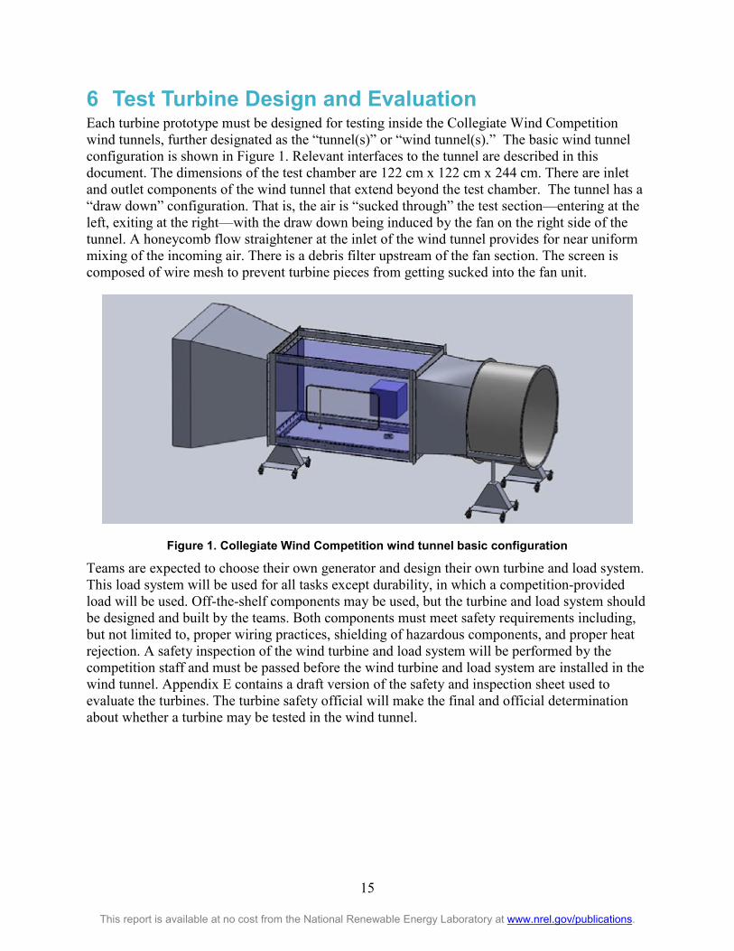
6 Test Turbine Design and Evaluation Each turbine prototype must be designed for testing inside the Collegiate Wind Competition wind tunnels, further designated as the “tunnel(s)” or “wind tunnel(s).” The basic wind tunnel configuration is shown in Figure 1. Relevant interfaces to the tunnel are described in this document. The dimensions of the test chamber are 122 cm x 122 cm x 244 cm. There are inlet and outlet components of the wind tunnel that extend beyond the test chamber. The tunnel has a “draw down” configuration. That is, the air is “sucked through” the test section—entering at the left, exiting at the right—with the draw down being induced by the fan on the right side of the tunnel. A honeycomb flow straightener at the inlet of the wind tunnel provides for near uniform mixing of the incoming air. There is a debris filter upstream of the fan section. The screen is composed of wire mesh to prevent turbine pieces from getting sucked into the fan unit.
Figure 1. Collegiate Wind Competition wind tunnel basic configuration
Teams are expected to choose their own generator and design their own turbine and load system. This load system will be used for all tasks except durability, in which a competition-provided load will be used. Off-the-shelf components may be used, but the turbine and load system should be designed and built by the teams. Both components must meet safety requirements including, but not limited to, proper wiring practices, shielding of hazardous components, and proper heat rejection. A safety inspection of the wind turbine and load system will be performed by the competition staff and must be passed before the wind turbine and load system are installed in the wind tunnel. Appendix E contains a draft version of the safety and inspection sheet used to evaluate the turbines. The turbine safety official will make the final and official determination about whether a turbine may be tested in the wind tunnel.

16
This report is available at no cost from the National Renewable Energy Laboratory at www.nrel.gov/publications.
6.1 Turbine and Load Design Requirements For the testing contest:
• The turbine must be designed to withstand continuous winds of up to 20 m/s.
• The tunnel base flange, where the turbine is mounted, will be subjected to yaw rates of up to 180° per second with a maximum of two full rotations from the initially installed position.
• At zero yaw angle, the entire turbine must fit within the volume specified below and shown in Figure 2.
Figure 2. Allowable turbine volume
o Rotor and nonrotor turbine parts must be contained in a 45 cm by 45 cm by 45 cm cube centered horizontally on the flange axis with its horizontal midplane located 60 cm ± 3 cm above the mounting flange.
o A 15-cm diameter cylinder around the vertical centerline of the mounting flange extending from the tunnel floor to the bottom of the cube can contain only nonrotor turbine parts. For this purpose, nonrotor turbine parts will be defined as anything that does not capture energy from the moving air.
o Other electronic components may also be located outside the tunnel. Within practical limits, there is no size restriction for these components. These components must be incorporated into closed enclosures that are fire safe and meet or exceed a NEMA type 1 rating. All components must be electrically insulated from the enclosures. Teams should also pay careful attention to the standards for ventilation of these enclosures.
o All electrical cables leading from the turbine to the electronic components located outside the tunnel must be in cable form (no individual strands) and have

17
This report is available at no cost from the National Renewable Energy Laboratory at www.nrel.gov/publications.
connectors. Screw terminals are not considered acceptable connectors. Individual strands or bare wires will result in disqualification for testing until remedied. Two or more individual strands twisted together or a multistrand cable is permissible as long it has a connector on the end.
o All turbines must fit through the turbine door (61 cm by 122 cm) in one assembly with no additional assembly occurring inside the tunnel other than attachment to the base flange and connection to external electrical components.
• The wind turbine system must be mountable on the test stand at the specified location within the wind tunnel:
o The turbine base plate must be constructed of material no thicker than 16.1 mm. It should be designed to fit over three studs where it will be secured to the tunnel base flange with nuts. Figure 3 shows the bolt pattern and sizing of this flange.
o The tunnel base flange incorporates a turntable to generate yawed flow. Figure 3 details the dimension for the hole in this base flange to allow cables and connectors to pass through.
o Teams are free to apply their engineering judgment to their own base plate design, keeping in mind that the turbine base must be designed with adequate tolerances such that it can be attached safely to the base flange in the wind tunnel and able to withstand the tension of the mounting studs when torqued to approximately 50 Newton-meters.
Figure 3. Base flange dimensions for turbine attachment to tunnel (dimensions in cm)
o The turbine base plate will be tied to earth ground. To prevent overvoltage of the tunnel data acquisition system, turbine electrical system ground(s) must be electrically tied to this base plate with a 100 kΩ or lower resistance connection.

18
This report is available at no cost from the National Renewable Energy Laboratory at www.nrel.gov/publications.
• Wires should exit the tunnel at the turbine base through the center of the turntable. From this point, each team must provide a length of wire approximately 1 meter in length to reach the point of common coupling (PCC) on the judge’s side of the tunnel, where they will join with the load connectors from either of the two loading systems. The competition instrumentation will be inserted at this point (Figure 4). A table will be provided to display the load on the opposite side of the tunnel from the judges and the PCC. Teams should provide adequate lengths of wire to run from the PCC to the load to accommodate their desired load display arrangement on the table.
Figure 4. Load, turbine, storage element, and point of common coupling arrangement
• Voltage must be direct current (DC) at the PCC and is required to be at or below 48 volts at all times. Exceeding this voltage limit will result in a zero testing contest score. Teams may then attempt to fix the overvoltage and use their re-test if available.
• Energy storage elements, such as capacitors and/or inductors, may be used in both the turbine and the load but not for bulk energy storage on the turbine side of the PCC.
o Additionally, for the turbine side of the PCC:
No batteries of any type or excessively large capacitors6 will be permitted, except for the storage element provided by the competition organizers.
6 No single capacitor (or electrical combination thereof) can have a storage capability of greater than 1 Joule, calculated as 1/2CV2 , where C is capacitance in farads and V is the rated voltage of the capacitor.

19
This report is available at no cost from the National Renewable Energy Laboratory at www.nrel.gov/publications.
Turbine components may draw from the load but must register a zero state of charge at the beginning of the test.
Verification of zero energy at the start of the test will be accomplished by the use of the competition data acquisition system to measure zero current flow into the load at the PCC. Any questionable elements are subject to additional verification of zero energy by the testing team through the use of a multimeter or similar device before the testing begins.
Teams must show that all components utilized to control the turbine reside on the turbine side of the PCC. During the safety inspection, students must adequately demonstrate to the judges through verbal explanation, wiring diagrams, software architecture, and similar tools that the load is not controlling the turbine.
Wired connections between the turbine and load external of the PCC are allowed, but must be optically isolated. Teams must show that any connection external of the PCC, either wired or wireless, is being used for monitoring or logging only—not active command and control.
o For the load side of the PCC:
Bulk energy storage is allowed, provided it is utilized in a safe and reliable manner.
To run the load, 120 VAC will be provided, if desired.
• The storage element, provided by the judges, is detailed in Figure 5. It consists of a Maxwell Technologies’ 16-V small cell ultracapacitor module (Manuf. P/N: BMOD0058 E016 B02). If a team exceeds the 16V rating of this module as measured by the competition data acquisition system, the tunnel controls will immediately disconnect it from the PCC.
Figure 5. Competition-provided ultracapacitor storage element
• The competition will provide a variable-resistance load to be used during the durability portion of the test.
• To interface with the PCC, the competition load, and the storage element, wires should be terminated with Anderson Powerpole connectors, PP15-45 (a red and a black, for positive and negative, respectively). Teams are expected to provide their own Powerpole connectors of appropriate size: 15A, 30 A, or 45 A, which are specified to handle wire gauges from 10

20
This report is available at no cost from the National Renewable Energy Laboratory at www.nrel.gov/publications.
American wire gauge (AWG) through 20 AWG. Each team can choose the wire size it wants to use in this range as long as the appropriate current-carrying capacities are taken into consideration. All three pin sizes fit into the same housing (PP15-45), as stated above.
• Turbines must be capable of shutting down on command as well as when electrically disconnected from the load. During the contest:
o The judges will initiate an electrical shutdown by signaling the students to disconnect the load connection to the PCC.
o Manual shutdown will be triggered by a competition-provided, normally closed switch that is typical of industrial emergency stop circuits and will be located outside the tunnel. Judges will initiate a manual shutdown by signaling the students to depress the switch, causing the circuit to open. To connect to this circuit:
Each team must provide a cable containing two wires (22–28 AWG) that is at least 2 meters in length exiting the tunnel at the base flange to reach this switch. This cable should be terminated, prior to the competition, with a standard JST RCY female receptacle housing connector (Manuf. P/N: SYR-02T housing using SYM-001T-P0.6(N) for the corresponding male pin contacts), Figure 6.7
Figure 6. Team-provided connection to the manual shutdown interface
The competition switch will be terminated with the corresponding polarity JST RCY male plug (Manuf. P/N: SYP-02T-1 plug housing using SYF-001T-P0.6(LF)(SN) socket contacts), Figure 7.7
Figure 7. Competition-provided connector for manual shutdown interface
7 Note: in the remote-control aircraft community, these connector pairs are commonly referred to as “JST BEC” connectors and are available from a variety of sources, including Digi-Key.

21
This report is available at no cost from the National Renewable Energy Laboratory at www.nrel.gov/publications.
6.2 Testing Procedure The turbine-testing contest consists of a number of individual turbine tasks. This section describes the requirements of the individual tasks in which the turbine is expected to perform and the parameters of the testing conditions. Details on scoring algorithms and point allocations between individual tasks can be found in Appendix B, table B-7.
Testing provides teams with the opportunity to demonstrate their turbine’s performance through objective tasks—and the testing outcomes help determine if they have succeeded in developing a durable, safe, high-performing machine (performance is a strong indicator of a turbine’s ability to compete successfully in the marketplace).
Each turbine, along with its corresponding load system, will be tested in the competition wind tunnel. The contest will include the following tasks: turbine performance, turbine-rated rpm and power control, cut-in wind speed, turbine durability over a range of wind speeds and yaw positions, and turbine safety. Students will use their load for all tasks except durability, wherein a competition-provided load and storage element, described in Section 6.1, will be used.
All teams will follow the same prescribed schedule for testing in the wind tunnel. Only one team’s turbine will be tested at a time. Each team will have 35 minutes of tunnel time—5 minutes to install the turbine and up to 30 minutes of time that will include commissioning, testing, and uninstalling the turbine. This year, teams will be provided with a period of “commissioning time” prior to the scoring tasks starting during which the teams may ask for any wind speed from 5 m/s to 11 m/s and do any work on their turbine or electronics they deem necessary to get their systems up and running. Teams may use as much of their 30 minutes for commissioning as they would like, keeping in mind that the testing tasks will be stopped promptly 5 minutes prior to the end of the team’s allotted period to allow time to remove the turbine. The complete series of testing tasks are expected to require between 15-20 minutes to complete, depending on how fast the turbine stabilizes at certain testing conditions.
Additionally, teams may signal at any time during the test that they would like to turn the session into a practice session. In this case, the score for this attempt will be zeroed and the team can use their remaining time to troubleshoot and learn about their turbine’s performance in preparation for an additional session, if they have one available.
If there are unforeseen delays caused by the organizers (e.g., a wind tunnel issue or power outage), the time spent rectifying the problem will not be included as part of the team’s allowable minutes. Team members will not be allowed to touch their turbines or controls during the test except during commissioning or to manually restart their turbine if they fail to restart after a safety shutdown test. Turbine failure is defined as anything out of the ordinary such as cracking, breaking, pieces falling off, smoking, sparking, or failure to produce an electrical current and will be cause for immediate stoppage of testing.
If a team wants to retest their turbine for any reason, team members may request a single retest during the provided makeup sessions later in the competition. The retest will be a full test and all scores from the first test will be replaced, regardless of the turbine’s performance in the retest. Retesting signups will be conducted on a first-come, first-served basis after the scores have been

22
This report is available at no cost from the National Renewable Energy Laboratory at www.nrel.gov/publications.
announced from the first round of testing. Competition organizers reserve the right to work with the teams and reorder this schedule based on additional constraints during the retest period.
Students are encouraged to bring spare components and/or assemblies and to design their turbines so that damaged parts or assemblies can be easily replaced. However, it is important to keep in mind that the turbine configuration throughout the entire competition must remain substantially the same as what is documented in the written report to achieve a testing score. For example, the number of blades, rotor axis, turbine configuration, and operating voltage must remain the same. Teams with questions about any changes or altered turbine components or assemblies are encouraged to discuss their particular situation with the organizers well ahead of the competition to ensure they are adhering to this requirement.
6.2.1 Power Curve Performance Task The objective of this task is to test each turbine over a range of wind speeds to determine a power curve. It is meant to be a direct comparison of power performance between turbines, which is one factor by which real turbines are judged.
Each turbine will be tested at integer wind speeds between 5 and 11 m/s inclusive for a maximum duration of 60 seconds (s) or less, with the stated intent of obtaining a “stable” power reading, which is defined as stable in rpm and power per electronic testing devices during the test period. As power output may fluctuate, for purposes of this task, the allowable power outputs to be included in the maximum average power (per electronic testing devices) during any 5-s interval will be defined as +/-10% of the maximum average power.
6.2.2 Control of Rated Power and Rotor Speed Task Wind turbines have to withstand high winds without damage to their mechanical or electrical components. Because wind power is proportional to the cube of wind speed, the energy available in the wind quickly becomes very high as wind speed increases. To control rising mechanical and electrical loads, turbines must be able to limit their rotational speed and output power in these high-wind conditions.
In this task, each turbine will be subjected to two wind speed bins chosen by the organizers between 12 m/s and 20 m/s and turbine performance in those two bins will be compared to the performance in the 11m/s bin. The turbines are expected to keep the rpm at or below the rpm determined at 11 m/s and to keep the power at the same level as is determined at 11 m/s.
6.2.3 Cut-In Wind Speed Task Cut-in wind speed—the lowest wind speed at which a turbine produces power—is one of the characteristics that can differentiate one turbine as being better suited to lower wind-speed regimes than others. Lower wind speed is generally deemed more desirable in the small turbine market.
In this task, each turbine will be subjected to slowly increasing wind speeds, from 2.5 m/s to 5 m/s, to determine the cut-in wind speed. For this task, “producing power” is defined as achieving a positive current (A) average over a 5-s interval at a steady wind speed.

23
This report is available at no cost from the National Renewable Energy Laboratory at www.nrel.gov/publications.
6.2.4 Durability Task Turbines are expected to perform over the long term and will be subjected to a wide variety of weather conditions. Producing power effectively and over the course of the turbine’s lifetime are desirable design qualities.
In this task, each turbine will be subjected to the same prescribed variable wind speed and direction function. Speeds will never be less than 6 m/s or greater than the maximum continuous wind speed specified in Section 6.1 over a 5-minute test period. Yawed flow will be achieved using the tunnel’s turntable governed by the limits set in Section 6.1. This test helps verify that the turbine can function over a wide range of operating conditions.
The scoring for this task will be based on the turbine system’s ability to maintain a constant 5 V output into a competition-provided variable-resistance load, using the output from the turbine and the storage capacity of the competition-provided storage element, described in Section 6.1. Maximum load demand will be 40W. The storage element will start at a discharged state. The first minute of wind will be provided so that energy can be stored in the storage element. No yaw motion or load will be used during this minute, and no score will be generated. After the end of the first minute, 2 minutes of variable wind and variable load with no yaw will be scored. The fourth and fifth minutes will be similar to the previous 2 minutes but with yaw motion added.
To summarize:
• Minute 1: no load, no yaw, no scoring, allowing time to charge the storage element.
• Minutes 2 and 3: variable load, no yaw, scores generated, charge and discharge the storage element as needed.
• Minutes 4 and 5: variable load, yaw motion, scores generated, charge and discharge the storage element as needed.
6.2.5 Safety Task Safety is of utmost importance to turbine designers and manufacturers. To be certified, turbines must be able to safely shut down rapidly and with a fail-safe shutdown capability. Turbines must shut down when disconnected from the grid as well as manually upon command, as described in Section 6.1. Each team may choose to address these shutdown scenarios with one or two systems or mechanisms.
In this task, the turbine will be required to safely shut down at two different times during the testing period at any wind speed—up to the maximum continuous wind speed specified in Section 6.1. For each turbine, the shutdown process will be initiated once “on command” and separately by electrical disconnect. The turbine must also be capable of restarting at any wind speed above 5 m/s. For the purposes of this task, “shutdown” is defined as dropping below 10% of the maximum 5-s bin average rpm achieved during the power performance testing. This reduction in rpm must occur within 10 s and remain below the limit indefinitely. If the turbine fails to successfully restart, the team may work on their electronics to manually restart their turbine, resulting in a zero score for the restart portion of the task.

24
This report is available at no cost from the National Renewable Energy Laboratory at www.nrel.gov/publications.
7 Siting Challenge This year, teams will participate in a scored wind farm siting challenge. The contest will have two elements. Part one is an activity that must be completed prior to the event, with the deliverable, a poster, being judged during the competition. Part two will be conducted during the competition and will build on the experience gained in part one. Professional siting experts will be at the competition to conduct the on-site activity and judge both elements of the contest. Feedback from wind siting experts will be shared with each team.
It will be beneficial to develop a basic understanding of siting elements prior to beginning part one. This could include: understanding wind resource data and performance estimation, factors that affect economics, setbacks, terrain effects, environmental issues, transportation constraints, transmission design, permitting requirements, turbine technology and performance variables (i.e., wakes, inflow, availability, and site-specific losses).
Below is a description of each element of the siting contest. For details on the evaluation metrics, see the rubrics in Appendix B.
7.1 Part 1: Research and Develop a Plan for a 100-MW Wind Farm in the Team’s Home State
Teams must conduct a regional assessment of wind farm development opportunities within their region and create a rough development plan. Team members must be prepared to explain their process to judges at the competition, as follows: 1. Select the top three development sites within 100 miles of the team’s school.
a. This site cannot be offshore nor can it be an existing land-based site. b. Be prepared to explain how these sites were chosen. Some considerations may
include wind resource, terrain, landowners, vegetation, access to transmission, transportation access, environmental, and community factors.
2. Choose one of the three proposed sites and develop a preliminary wind farm design. a. Draft preliminary design:
i. Choose turbine type, hub height, rotor diameter, number of turbines. ii. Define project boundary
b. Conduct a site visit: i. Record observations about terrain, vegetation, wildlife, and so on.
c. Permitting: i. Research local ordinances.
ii. Research sensitive species in the area, sensitive ecosystems, impacts to wildlife, and mitigation processes that have been successfully implemented in the past.
3. Finalize detailed design of the site plan. a. Collect wind resource information, contour data, roughness, and so on. b. Pick turbine locations. c. Plan site access roads. d. Plan transmission to nearest substation. e. Plan land leases.

25
This report is available at no cost from the National Renewable Energy Laboratory at www.nrel.gov/publications.
4. Conduct community education and outreach, which should include one of the following: a. Pitch project to planning and zoning commission, or b. Interview a county commissioner or planning board member, and present at a:
i. Town hall meeting. ii. Public open house.
iii. Lions or rotary club. For this exercise, be sure to emphasize that this is a project for a collegiate competition and there will be no real wind development so there is no confusion for the audience or unwanted feedback.
7.1.1 At the Competition At the competition, teams will present their proposed wind farm site plan during a private session with the siting judges who will represent a planning board or other government organization. This presentation should convey the most important details of the project, including discussions of the location choice, reason for the layout, potential community impacts and their mitigation approaches, and expected community benefits of the project. The teams will have 10 minutes to present their project with 5 minutes for questions from the siting judges. Teams may use up to two posters to represent the project including information such as project location, layout and turbine selection criteria. Each poster should be no larger than 3 by 4 feet. At the end of the presentation and question period the team can use the remainder of their time, approximately 10 minutes, to ask the judges questions in preparation for the on-site challenge (Part 2). Some of the items teams may want to include: • Why the team selected the site being proposed.
• Detailed design drawing of the site plan.
• The most important technical considerations, i.e., details of the turbine decision process, such as, turbine type/class by wind regime, hub height by shear, and rotor diameter by cost/net capacity factor balance.
• Details on any mitigation plans that arose from community feedback. The scoring criteria is provided in Appendix B, table B-5.
7.2 Part 2: Design a Wind Farm During the Competition Teams will complete a siting activity at the competition. This task will be similar to elements of both the preliminary and detailed design activities conducted prior to the competition but the site will be selected by the organizers. The site will represent a real or fictional location and will be the same area for all teams, but will not be within any of the competition teams’ local areas. The winner of the on-site siting challenge will balance competing objectives of maximizing power production while minimizing costs, and environmental and community impact. The scoring criteria is provided in Appendix B, table B-6.

26
This report is available at no cost from the National Renewable Energy Laboratory at www.nrel.gov/publications.
The contest will run as follows:
• Day 1: Teams will be given a siting challenge packet of the site area with detailed topography, wind regime and instructions for the challenge during the competition sign-in. This packet will be reviewed at the Rules & Logistics meeting for the first day. The provided materials will clearly identify all environmental and community elements that should be considered. Teams will have a full day to sketch a draft solution to the problem – this is the preliminary design layout. As stated above, teams will have the ability to ask questions of the siting judges about the challenge at the end of their siting presentation which will occur on the afternoon of the first day.
• Day 2: Teams will hand in their preliminary design layout, indicating proximity to communities, residences, sensitive habitat etc. Teams will then sit with one of the siting judges or competition staff to indicate the precise location of each turbine for their proposed wind farm using industry acceptance wind plant siting software, which will be the basis for the detailed siting layout. This siting tool will evaluate project energy produced and economics. The combination of the preliminary design packet and the final siting layout will be the basis for the final submission. The siting contest will be evaluated by the siting judges using the defined scoring criteria.

27
This report is available at no cost from the National Renewable Energy Laboratory at www.nrel.gov/publications.
Glossary Bull pen Each team is provided an assigned area, known as a bull pen, to use as a
central location throughout the competition to work on their turbines, prepare for various contests, regroup, and showcase their hard work throughout the year to the public.
Competition
The competition is all aspects and activities leading up to, through, and following the event. It is the subcontract project agreement between the competitively selected collegiate teams and the National Renewable Energy Laboratory, the contests, products, and event, collectively referred to for a given year as the U.S. Department of Energy Collegiate Wind Competition.
Contests
The competition consists of several contests with multiple products.
Event The event is when and where the teams compete in the contests.
Products
Products are what the team builds, writes, submits, and brings to compete in the competition.
Test
The overall time period in the wind tunnel during which each team’s turbine is subject to various wind speeds and scored on the testing tasks.
Task
Each individual achievement goal of the test turbine that will be scored during the wind tunnel testing period.

28
This report is available at no cost from the National Renewable Energy Laboratory at www.nrel.gov/publications.
Appendix A. Timeline and Schedule Competition Timeline The 2018 competition timeline is shown in Table A-1.
Table A-1. 2018 Competition Timeline and Related Activities
Month/Year Competition Activity Summer 2017 Release of competition rules and requirements
Fall 2017 Concept development
Spring 2018 Product development and testing
May 2018 Competition takes place
June 2018 The winning wind turbine is put on display at the U.S. Department of Energy headquarters in Washington, D.C. A review meeting/conference call is held to review the competition and make recommendations for the next event.
Event Schedule The competition event is expected to be held in accordance with the schedule provided in Table A-2; however, times are subject to change anytime up until the event. Breakfast and lunch will be provided each day of the competition. Organizers will distribute an updated schedule to participants in advance. Teams are encouraged to pick up any shipments from the competition location the day before event sign-in.

29
This report is available at no cost from the National Renewable Energy Laboratory at www.nrel.gov/publications.
Table A-2. Competition Event Schedule
Day 1 (Tuesday 5/8) 8 a.m.—9 a.m. Competition sign-in (receive welcome materials)/decorate bullpens
9 a.m.–10 a.m. Welcome meeting with teams and PIs: rules and logistics
10 a.m.—6 p.m. Turbine/load safety inspections and wind tunnel practice
Siting challenge part one (starting at 11:15 a.m.)
Day 2 (Wednesday 5/9)
8 a.m.— 8:20 a.m.
Announcements
8:30 a.m.—5 p.m. Turbine performance testing
Design presentation judging
Siting challenge part two
5 p.m.—6 p.m. Announcements and sign up for turbine testing makeup
Day 3 (Thursday 5/10)
7:30 a.m.—3:30 p.m. Turbine performance testing makeup
Announcements (8:15 a.m.)
Public pitches (9:10 a.m. – 2 p.m.)
CWC team/industry expo
3:30 p.m.—5 p.m. Award ceremony and reception
General activities with all participants
Turbine performance testing activities
Public pitches (public)
Design presentation (private)
Siting contest activities

30
This report is available at no cost from the National Renewable Energy Laboratory at www.nrel.gov/publications.
Appendix B. Rubrics Products
Table B-1. Scoring Summary for the Competition Products (1,000 Points Total)
Competition Contests
Total Scores
Products
Written Report (250)
Private Presentation
(100)
Public Pitch (125)
Siting Poster (100)
On-Site Siting Design
(100)
Turbine and Load
(325)
Business Plan 250 125 - 125 - - - Technical Design 225 125 100 - - - - Turbine Testing 325 - - - - - 325 Siting Challenge 200 - - - 100 100 -
Written Report
Table B-2. Scoring Rubric for the Written Report (250 Points Total)*, **
Description Possible Points
Score
Business Plan (125 points) Market deployment feasibility (marketability, buildability, public/market acceptance) 25 Risk recognition and management 25 Innovation, creativity, and originality 25 Presentation (i.e., how well the plan is presented in writing) 15 Financial analysis and documentation 25 Cohesiveness with the market turbine conceptual-level design and executive summary 10
Subtotal Technical Design (125 points) Design objective description for market and test turbines including integration with the business plan
15
Market turbine: Conceptual-level design 15 Test turbine: Static performance analysis 13 Test turbine: Mechanical loads analysis and associated safety factors 13 Test turbine: Electrical analysis (including both loads and storage element) 13 Test turbine: Controls analysis (including storage element) 13 Test turbine: Software documentation and description (including storage element if app.) 10 Test turbine: Results from laboratory and/or field testing 20 Test turbine: Engineering diagrams including mechanical and electrical drawings 13
Subtotal Total
* 5% of total allowable points, distributed evenly across each contest section, will be deducted for each day the report is late.
**Formatting requirements are in place to ensure an equal amount of space for all teams to tell their stories to the judges. Reports not formatted to the requirements in Section 4 that are deemed to be utilizing more than the allotted space will be penalized at the discretion of the judges proportional to the infraction. Furthermore, extra pages will be ignored.

31
This report is available at no cost from the National Renewable Energy Laboratory at www.nrel.gov/publications.
Private Presentation Table B-3. Scoring Rubric for the Private Presentation (100 Points Total)
Description Possible Points
Score
Technical Design (100 points) Design objective description for market and test turbines including integration with the business plan
20
Market turbine: Clear communication of conceptual-level plans 15 Test turbine: Clear communication of static performance analysis, mechanical loads analysis, and associated safety factors
15
Test turbine: Clear communication and justification of electrical and controls analysis 15 Test turbine: Clear communication of results from laboratory and/or field testing 15 Practiced and polished presentation style, professional appearance, and manner with effective materials and props where applicable
20
Subtotal Total
Public Pitch
Table B-4. Scoring Rubric for the Public Pitch (125 Points Total)*, **
Description Possible Points
Score
Business Plan (125 points) Compelling narrative of inspiration and purpose behind the business plan 25 Demonstrates thorough market analysis and triple bottom line risk assessment 25 Demonstrates consideration of deployment issues and challenges 15 Illustrates integration with the technical design and turbine brought to the competition for testing
15
Practiced and polished presentation style, professional appearance, and manner 15 High-quality graphics, media, and props to support presentation 15 Clear communication of technical topics to broader wind energy community 15
Subtotal Total
* 5% of total allowable points, distributed evenly, will be deducted for each hour the presentation is late.

32
This report is available at no cost from the National Renewable Energy Laboratory at www.nrel.gov/publications.
Siting Challenge Table B-5. Siting Challenge Rubric – Part 1: Proposed Wind Farm Plans (100 Points Total)
Description Possible Points
Score
Site Plan (100 points) Documentation of down select from three sites and public presentation of the project 30 Site specification and identification of potential siting challenges 20 Detailed site layout including infrastructure while minimizing cost and local impact 20 Articulation of impact mitigation approaches 10 Professionalism and accessibility of presentation and supporting materials 20
Total
Table B-6. Siting Challenge Rubric – Part 2: On-Site Design Challenge (100 Points Total)
Description Possible Points
Score
LCOE (55 points) Lowest cost of energy 55
Subtotal Community Impact (20 points) Noise impact 5 Visual impact 5 Setback from roads 5 Setback from agricultural settlements or towns 5
Subtotal Environmental Impact (25 points) Compactness/total footprint area (more points for smaller footprint) 5 Sensitive habitat impacted (less points the more habitat impacted) 5 Species habitat impacted (less points the more species habitat impacted) 5 Amount of prime farmland impacted (less points the more farmland impacted) 5 Amount of clearing required (less points the more clearing required) 5
Subtotal Total

33
This report is available at no cost from the National Renewable Energy Laboratory at www.nrel.gov/publications.
Turbine Performance Testing Table B-7. Scoring Rubric for Turbine Performance Testing (325 Points Total)
Description Possible Points
Score
Power curve performance task 75
Control of rated power 25
Control of rated speed 25
Cut-in wind speed task 40
Durability task 100
Safety task 60
Total
Scoring algorithms for each testing task are described in the next sections.
Power Curve Performance Task A total score for this task will be calculated according to Table B-5 by multiplying each power measurement in watts in 1-m/s wind speed intervals from 5 m/s to 11 m/s by the factor given. If power is not stable within the specified tolerance in Section 6.2.1, the score for the bin will be zero.
Table B-8. Weighting for the Power Curve Performance Task
Wind Speed (m/s) Factor 5 1.0
6 1.2
7 1.2
8 1.0
9 0.7
10 0.4
11 0.2

34
This report is available at no cost from the National Renewable Energy Laboratory at www.nrel.gov/publications.
Control of Rated Power and Rotor Speed Task Scores for power will be calculated according to the following:
𝑟𝑟𝑝𝑝 ≡𝑚𝑚𝑚𝑚𝑚𝑚𝑚𝑚𝑚𝑚𝑟𝑟𝑚𝑚𝑚𝑚 𝑝𝑝𝑝𝑝𝑝𝑝𝑚𝑚𝑟𝑟 𝑖𝑖𝑖𝑖 𝑏𝑏𝑖𝑖𝑖𝑖 𝑝𝑝𝑜𝑜 𝑖𝑖𝑖𝑖𝑖𝑖𝑚𝑚𝑟𝑟𝑚𝑚𝑚𝑚𝑖𝑖
𝑚𝑚𝑚𝑚𝑚𝑚𝑚𝑚𝑚𝑚𝑟𝑟𝑚𝑚𝑚𝑚 𝑝𝑝𝑝𝑝𝑝𝑝𝑚𝑚𝑟𝑟 𝑚𝑚𝑖𝑖 11 𝑚𝑚/𝑚𝑚
𝐵𝐵𝑖𝑖𝑖𝑖 𝑆𝑆𝑆𝑆𝑝𝑝𝑟𝑟𝑚𝑚 = 25tanh (−20 ∗ 𝑟𝑟𝑝𝑝 − 1 + 𝜋𝜋) + 1
[tanh (𝜋𝜋) + 1]
In Figure B-1, a ratio, rp, of 1.000 represents perfect power control at exactly the same value as was measured in the 11-m/s bin. The weighting shown will be multiplied by 25 for the two selected bins to obtain scores for each bin.
Figure B-1. Score weighting based on power ratio for control of rated power task

35
This report is available at no cost from the National Renewable Energy Laboratory at www.nrel.gov/publications.
Scores for rotor speed control will be calculated according to the following:
𝑟𝑟𝑠𝑠 ≡𝑚𝑚𝑚𝑚𝑚𝑚𝑚𝑚𝑚𝑚𝑟𝑟𝑚𝑚𝑚𝑚 𝑚𝑚𝑝𝑝𝑚𝑚𝑚𝑚𝑚𝑚 𝑖𝑖𝑖𝑖 𝑏𝑏𝑖𝑖𝑖𝑖 𝑝𝑝𝑜𝑜 𝑖𝑖𝑖𝑖𝑖𝑖𝑚𝑚𝑟𝑟𝑚𝑚𝑚𝑚𝑖𝑖
𝑚𝑚𝑚𝑚𝑚𝑚𝑚𝑚𝑚𝑚𝑟𝑟𝑚𝑚𝑚𝑚 𝑚𝑚𝑝𝑝𝑚𝑚𝑚𝑚𝑚𝑚 𝑚𝑚𝑖𝑖 11 𝑚𝑚/𝑚𝑚
0 < 𝑟𝑟𝑠𝑠 < 1.03 → 𝐵𝐵𝑖𝑖𝑖𝑖 𝑆𝑆𝑆𝑆𝑝𝑝𝑟𝑟𝑚𝑚 = 20
𝑟𝑟𝑠𝑠 ≥ 1.03 → 𝐵𝐵𝑖𝑖𝑖𝑖 𝑆𝑆𝑆𝑆𝑝𝑝𝑟𝑟𝑚𝑚 = 25[tanh (−20 ∗ |𝑟𝑟𝑠𝑠 − 1.03| + 𝜋𝜋) + 1]
[tanh (𝜋𝜋) + 1]
In Figure B-2, a ratio, rs, of 1.000 represents the perfect rotor speed control at exactly the same value as was measured in the 11-m/s bin. The weighting shown includes a 3% buffer above and infinite buffer below that speed to obtain full points. The weighting shown will be multiplied by 25 for the two selected bins to obtain scores for each bin.
Figure B-2. Score weighting based on rpm ratio for control of rated rotor speed task

36
This report is available at no cost from the National Renewable Energy Laboratory at www.nrel.gov/publications.
Durability Task This portion of the competition will be scored on a second-by-second basis for minutes 2 through 5 of the task. Exceeding the rated voltage of the capacitive storage element will result in a zero score for the remainder of the durability test. Each second during minutes 2 through 5 will be scored according to the ratio between the measured average load voltage during that second and the 5 V target voltage according to the following:
𝑟𝑟𝑣𝑣 ≡𝑚𝑚𝑚𝑚𝑚𝑚𝑚𝑚𝑚𝑚𝑟𝑟𝑚𝑚𝑚𝑚 𝑣𝑣𝑝𝑝𝑣𝑣𝑖𝑖𝑚𝑚𝑣𝑣𝑚𝑚
5 𝑉𝑉𝑝𝑝𝑣𝑣𝑖𝑖𝑚𝑚
0.95 < 𝑟𝑟𝑣𝑣 < 1.05 → 𝑃𝑃𝑚𝑚𝑟𝑟𝑖𝑖𝑝𝑝𝑚𝑚 𝑆𝑆𝑆𝑆𝑝𝑝𝑟𝑟𝑚𝑚 =100
4 ∗ 60= 0.416
𝑟𝑟𝑣𝑣 ≥ 1.05 → 𝑃𝑃𝑚𝑚𝑟𝑟𝑖𝑖𝑝𝑝𝑚𝑚 𝑆𝑆𝑆𝑆𝑝𝑝𝑟𝑟𝑚𝑚 = 0.416[tanh(−20 ∗ |𝑟𝑟𝑣𝑣 − 1.05| + 𝜋𝜋) + 1]
[tanh(𝜋𝜋) + 1]
𝑟𝑟𝑣𝑣 ≤ 0.95 → 𝑃𝑃𝑚𝑚𝑟𝑟𝑖𝑖𝑝𝑝𝑚𝑚 𝑆𝑆𝑆𝑆𝑝𝑝𝑟𝑟𝑚𝑚 = 0.416[tanh (−20 ∗ |𝑟𝑟𝑣𝑣 − 0.95| + 𝜋𝜋) + 1]
[tanh (𝜋𝜋) + 1]
𝑇𝑇𝑚𝑚𝑚𝑚𝑇𝑇 𝑆𝑆𝑆𝑆𝑝𝑝𝑟𝑟𝑚𝑚 = (𝑃𝑃𝑚𝑚𝑟𝑟𝑖𝑖𝑝𝑝𝑚𝑚 𝑆𝑆𝑆𝑆𝑝𝑝𝑟𝑟𝑚𝑚)𝑖𝑖
240
𝑖𝑖=1
The unscaled weighting function used in the equations provided here is shown in Figure B-3.
Figure B-3. Score weighting based on voltage for durability task

37
This report is available at no cost from the National Renewable Energy Laboratory at www.nrel.gov/publications.
Cut-In Wind Speed Task A team will earn eight points for each half m/s bin below 5 m/s, inclusive of the lower bound and exclusive of the upper bound in which they can produce power, as defined in the cut-in wind speed task description (Section 6.2.3), up to the maximum score of 40 points for this task. The team receives one score based on its cut-in wind speed.
Safety Tasks The safety task is scored on a pass/fail basis in two parts, governed by the limits set forth in the safety task description (see Section 6.2.5). If the turbine achieves a successful shutdown upon manual initiation, the team will receive 20 points. If the turbine automatically restarts, the team will receive an additional 10 points. If the team has to manually restart the turbine, the team will receive zero points for the restart. If the turbine achieves a successful shutdown when disconnected from the load system and subsequent restart when reconnected, the team will receive an additional 20 points. If the turbine automatically restarts the team will receive an additional 10 points. If the team has to manually restart the turbine, the team will receive zero points for the restart.

38
This report is available at no cost from the National Renewable Energy Laboratory at www.nrel.gov/publications.
Appendix C. Communications and Business Operations External Communications The website will showcase the various elements of the competition, ongoing collegiate team engagement, and information about how to participate in future competitions. The website will also feature important documents such as this manual and the Collegiate Wind Competition identity guidelines. The identity guidelines provide information about how the competition name, logo, and visual identity can be used.
Internal Communications It is each team’s responsibility to stay abreast of the latest competition communications from the organizers. Communication between the teams and the organizers occurs via one or more of the following:
• Google Group. Official communications suitable for viewing by all team members and organizers will be posted on the Google Group message board. Instructions for joining Google Group will be provided by NREL to the teams following each team’s commitment to participate.
• Dropbox. This tool is used by the organizers and teams to transfer large files such as competition products. Notification of, or requests for, file transfers are made via the Google Group or email.
• Conference calls. Teams are strongly encouraged to participate in scheduled conference calls with the organizers. Invitations and instructions for participation in conference calls are provided by the competition operations manager via email until the Google Group has been established; then provided via the Google Group thereafter.
• Meetings during event. Meetings will be held daily throughout the event.
• Email. For expediency, and to protect confidentiality, the organizers may choose to communicate with teams via team members’ email addresses as listed in the Google Group database; however, most official communications occur via the Google Group message board.
Branding Team members agree to the use of their names, likenesses, content, graphics, and photos in any communication materials issued by the organizers and event sponsors.
Content and images (graphics and photos), and any publications in which the content and images appear, may be viewed and made available to the general public via the websites of the U.S. Department of Energy, National Renewable Energy Laboratory, and event sponsors with unrestricted use.
The organizers and event sponsors will make all reasonable efforts to credit the sources of content and images, although they may be published without. To ensure proper usage of and credit for images, teams should submit photos and graphics through the competition Dropbox.

39
This report is available at no cost from the National Renewable Energy Laboratory at www.nrel.gov/publications.
Teams are encouraged to develop a brand and platform for their turbines and teams. This platform, which may include web pages, Facebook, or other social media, outreach material, and team T-shirts, are welcomed during the competition. The use of the competition logo or name as part of individual school/team branding and platform is covered by the identity guidelines provided. Examples of good team branding will be provided prior to the competition; however, all branding and social outreach should conform to the safety and conduct provisions described in Section 2.3. All team branding should be of high quality and be provided in a professional context fitting for a national scale industry event.
Teams are expected to set up a professional space in their bull pens to highlight the team’s branding. This can include the turbine design, siting posters, team logo, and school information. The bull pens are your chance to showcase all the work you have put into your project over the course of the year and the best way to communicate your efforts to the industry, especially at the final industry networking event.
Teams will be expected to utilize their established platform for outreach during the competition. While branding and platform will not be included in the overall scoring, the team that can garner the most public support via social platforms will be honored with a People’s Choice Award.
Confidentiality and Intellectual Property There are portions of the competition that are decidedly open to the public for purposes of generating interest and providing general information. In addition, team members should keep in mind that various media outlets may be present during the competition. Any information made known and/or discussed should be expected to receive widespread and uncontrolled dissemination. Teams should consider in advance what level of information regarding all aspects of their turbine and turbine design they desire to have publicly available versus information that provides a competitive advantage, is critical to their performance in the competition, or is of a “proprietary” nature and essential to potential future business endeavors.
Judging and Scoring Panels of judges are responsible for scoring team performance in each contest (e.g., technical design, turbine testing, and so on). The judges will have detailed expertise related to the content they are responsible for evaluating. Each panel will also include diverse backgrounds that allow the judges to evaluate performance from a variety of angles.
Competition organizers will ensure that, to the extent possible, judges will not:
• Have personal or financial interests in, or be an employee, officer, director, or agent of any entity that is a registered participant in the competition.
• Have a familial or financial relationship with an individual who is a registered participant.
• Provide advice to teams, although they can provide clarification on the judging process.
• Discuss team performance with other teams or their advisors.
Names of the selected judges will be announced prior to the 2018 Collegiate Wind Competition.

40
This report is available at no cost from the National Renewable Energy Laboratory at www.nrel.gov/publications.
Judging Rubrics Judges will use detailed scoring rubrics to evaluate team performance in each of the categories. These rubrics give all participants a clear idea of what they will be evaluated on in each contest.
Products submitted prior to the event will be thoroughly reviewed and evaluated by the judges. Each judge will complete a rubric independently as the team is competing or based on the review of submitted products. At the completion of each event segment, judges will discuss each team’s performance before finalizing the rubrics. The team of judges will submit one unified rubric to the head rules official for scoring purposes.
Team Feedback In an effort to provide as much feedback as possible, teams will receive copies of the scored rubrics, which will be provided following completion of the competition. Teams will also receive a short narrative that is derived from the judges’ deliberations after each team’s presentation. Teams will also receive copies of notes judges may have written on the individual rubric forms.

41
This report is available at no cost from the National Renewable Energy Laboratory at www.nrel.gov/publications.
Appendix D. Product Submission Instructions Submittals are considered on time if they are received by the competition manager by the respective due date stated in this document.
All products must be saved in the formats indicated (see each product section) and submitted to organizers packaged as a single .zip file.
Submission Locations Products due ahead of competition must be delivered to the competition Dropbox (a link will be provided in the Google Group). A folder for each team will be created, and it will be the team’s responsibility to provide email addresses for each student that needs upload access to the account.
Teams can submit early copies and updated revisions until the deadline. Each folder will be closed, or “unshared,” after the submission deadline. Late products will not be accepted.
PDF Requirements PDFs must meet the following criteria:
• Embedded fonts
• A minimum resolution of 300 dpi on all images.
Points to remember include:
• Creating a PDF from scans, or by outputting the content into a raster image format (e.g., .jpg, .tiff, .png, or .gif) and then creating a PDF from the images is not acceptable.
• All-raster PDFs are large files at 300 dpi but are of unacceptable quality at lower resolutions and are not scalable without degradation. These types of PDFs should be avoided.
Audio Visual Presentation Requirements Audio visual presentation format requirements include the following:
• If used, videos should be of a .MOV or H.264 compressed.MP4 (MPEG-4) file type with a resolution of 720 x 480.
• Presentations should be of 16:9 aspect ratio.
• No background music that violates U.S. copyright laws; all incorporated music must be an original or royalty-free composition and proof of licensing must be submitted with the final file and transcript.
Electronic File-Naming Instructions The required file-naming convention for all electronic files is:

42
This report is available at no cost from the National Renewable Energy Laboratory at www.nrel.gov/publications.
[TEAM ABBREVIATION]_[PRODUCT ABBREVIATION]_[SUBMISSION DATE (YYYY-MM-DD)].[EXTENSION]
Table D-1 presents a list of team names and abbreviations; Table D-2 lists product names and abbreviations.
Example: A report submitted by California Maritime Academy on April 23, 2018, would have the following file name: MARITIME_Report_2018-04-23.PDF.
Table D-1. Team Names and Abbreviations
Team Name Team Abbreviation
California Maritime Academy MARITIME
California State University, Chico CHICO
Iowa State University ISU
James Madison University JMU
Kansas State University KSU
Northern Arizona University NAU
Pennsylvania State University PSU
Seattle University SU
Texas Tech University TTU
Universidad del Turabo TURABO
University of Wisconsin-Madison UWM
Virginia Tech VT
Table D-2. Product Names and Abbreviations
Product Name Product Abbreviation
Written report Report
Public pitch presentation Pitch
Private presentation Priv_Pres
Product zip before competition Portfolio
Audio visual presentation (if applicable) AV
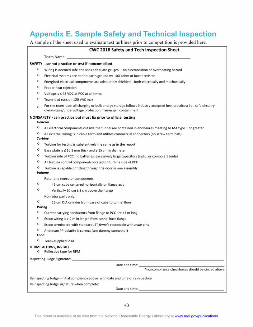
43
This report is available at no cost from the National Renewable Energy Laboratory at www.nrel.gov/publications.
Appendix E. Sample Safety and Technical Inspection A sample of the sheet used to evaluate test turbines prior to competition is provided here.
CWC 2018 Safety and Tech Inspection Sheet
Team Name: ____________________________________________________________ SAFETY - cannot practice or test if noncompliant
O Wiring is deemed safe and uses adequate gauges— no electrocution or overheating hazard
O Electrical systems are tied to earth ground w/ 100 kohm or lower resistor
O Energized electrical components are adequately shielded—both electrically and mechanically
O Proper heat rejection
O Voltage is ≤ 48 VDC at PCC at all times
O Team load runs on 120 VAC max
O For the team load: all charging or bulk energy storage follows industry-accepted best practices; i.e., safe circuitry
overvoltage/undervoltage protection, flame/spill containment
NONSAFETY - can practice but must fix prior to official testing
General
O All electrical components outside the tunnel are contained in enclosures meeting NEMA type 1 or greater
O All external wiring is in cable form and utilizes commercial connectors (no screw terminals)
Turbine
O Turbine for testing is substantively the same as in the report
O Base plate is ≤ 16.1 mm thick and ≤ 15 cm in diameter
O Turbine side of PCC: no batteries, excessively large capacitors (indiv. or combo ≤ 1 Joule)
O All turbine control components located on turbine side of PCC
O Turbine is capable of fitting through the door in one assembly
Volume
Rotor and nonrotor components:
O 45-cm cube centered horizontally on flange axis
O Vertically 60 cm ± 3 cm above the flange
Nonrotor parts only:
O 15-cm DIA cylinder from base of cube to tunnel floor
Wiring
O Current carrying conductors from flange to PCC are >1 m long
O Estop wiring is > 2 m in length from tunnel base flange
O Estop terminated with standard JST female receptacle with male pins
O Anderson PP polarity is correct (use dummy connector)
Load
O Team-supplied load
IF TIME ALLOWS, INSTALL:
O Reflective tape for RPM
Inspecting Judge Signature: __________________________________________________________________________________
Date and time: ______________________________________________
*noncompliance checkboxes should be circled above
Reinspecting Judge - Initial compliancy above with date and time of reinspection
Reinspecting Judge signature when complete: ___________________________________________________________________
Date and time: ______________________________________________