U.S. CONSUMER PRODUCT SAFETY COMMISSION DIRECTORATE … · U.S. CONSUMER PRODUCT SAFETY COMMISSION...
43
U.S. CONSUMER PRODUCT SAFETY COMMISSION DIRECTORATE FOR ENGINEERING SCIENCES DEMONSTRATION OF A REMOTE CARBON MONOXIDE SENSING AUTOMATIC SHUT OFF DEVICE FOR PORTABLE GENERATORS August 2006 Arthur Lee Electrical Engineer Division of Electrical Engineering Directorate for Engineering Sciences This report was prepared by the CPSC staff and has not been reviewed or approved by, and may not necessarily reflect the views of, the Commission.
Transcript of U.S. CONSUMER PRODUCT SAFETY COMMISSION DIRECTORATE … · U.S. CONSUMER PRODUCT SAFETY COMMISSION...

U.S. CONSUMER PRODUCT SAFETY COMMISSION
DIRECTORATE FOR ENGINEERING SCIENCES
DEMONSTRATION OF A REMOTE CARBON MONOXIDE SENSING
AUTOMATIC SHUT OFF DEVICE
FOR PORTABLE GENERATORS
August 2006
Arthur Lee Electrical Engineer
Division of Electrical Engineering Directorate for Engineering Sciences
This report was prepared by the CPSC staff and has not been reviewed or approved by, and may not necessarily reflect the views of, the Commission.

August 2006 ii
No Text on This Page

August 2006 i
Executive Summary Gasoline-powered portable generators are widely used to provide back-up electrical
power during extended power outages. One of the exhaust by-products from portable generators is carbon monoxide (CO), a colorless and odorless but highly lethal gas. In recent years, the proliferation and increased availability of portable generators at the consumer level have resulted in an increase in the number of CO related deaths. This increase is particularly evident in areas that have lost electrical power for extended periods due to severe weather.
In an effort to mitigate the CO hazards associated with the use of portable generators, in
2005, the U.S. Consumer Product Safety Commission (CPSC) staff conducted a proof-of-concept demonstration to integrate a CO detection system with a portable generator. The concept utilizes wireless technology combined with CO detection devices and off-the-shelf circuitry designed to provide an automatic shut off feature on portable generators. If elevated levels of CO accumulate in occupied areas of a household, the CO detection device sends a command to shut off the generator, thus eliminating the CO source. The following report details the design and testing of the demonstration system.

August 2006 ii
No Text on This Page

August 2006 iii
Table of Contents Executive Summary ....................................................................................................................................... i
1.0 Introduction............................................................................................................................................. 1 1.1 CO Alarms........................................................................................................................................... 1 1.2 Possible Technical Solution for Shutting Off a Portable Generator.................................................... 3
1.2.1 CO detection at the source............................................................................................................ 3 1.2.2 Remote CO detection .................................................................................................................... 5
2.0 Wireless Communication with CO Alarms and Portable Generators ..................................................... 6 2.1 Test Setup and Instrumentation........................................................................................................... 7 2.2 Incorporating a Wireless Transmitter in a CO Alarm ....................................................................... 10 2.3 Incorporating a Wireless Receiver on the Portable Generator .......................................................... 12
3.0 Testing of the Remote CO Detection System ....................................................................................... 15 3.1 Test Button Testing ........................................................................................................................... 16 3.2 Elevated CO Testing ......................................................................................................................... 17
4.0 Observations/Improvements ................................................................................................................. 23 4.1 Power................................................................................................................................................. 23 4.2 Relays ................................................................................................................................................ 24 4.3 CO Detection Unit............................................................................................................................. 24 4.4 Supervised System ............................................................................................................................ 25 4.5 Wireless Range.................................................................................................................................. 25 4.6 Feed-Back Indicators......................................................................................................................... 25 4.7 Self-Check......................................................................................................................................... 25
4.7.1 CO Detection Unit ...................................................................................................................... 26 4.7.2 Shut Off Unit ............................................................................................................................... 26
4.8 Cost.................................................................................................................................................... 26 5.0 Summary ............................................................................................................................................... 27
APPENDIX A Standard Operating Procedures for Assuring Minimum Carbon Monoxide Exposure During Demonstration of a Remote Carbon Monoxide Detection Shut Off Device for a Portable Generator ..................................................................................................................................................... A

August 2006 iv
List of Figures Figure 1. CO alarm helps detect elevated levels of CO in the home ............................................................ 2 Figure 2. Portable generator located in confined spaces or near an open window ....................................... 3 Figure 3. Portable generator located in the garage of an attached home ...................................................... 4 Figure 4. Portable generator located outside in a semi-confined space ........................................................ 5 Figure 5. CO detection device to remotely shut off the generator ................................................................ 5 Figure 6. Block diagram of a shut off device on a portable generator.......................................................... 7 Figure 7a. Example of a CO detection unit in a small home ........................................................................ 9 Figure 7b. Example of multiple CO detection units in a larger home ........................................................ 10 Figure 8. RF transmitter installed in a CO alarm........................................................................................ 11 Figure 9. Schematic of CO alarm and RF transmitter................................................................................. 11 Figure 10. Block diagram of receiver unit operation .................................................................................. 13 Figure 11. Wireless receiver and shut off unit ............................................................................................ 14 Figure 12. Schematic of shut off unit and generator................................................................................... 14 Figure 13. Wireless receiver/shut off unit on the generator........................................................................ 15 Figure 14. Adapter Response ...................................................................................................................... 16 Figure 15. Voltage response for remote shut off using the test button ....................................................... 17 Figure 16. Test 1 set-up with remote CO detection/shut off unit in the garage .......................................... 18 Figure 17. Remote CO detection/shut off unit in the garage disabling the generator................................. 19 Figure 18. Test 2 set-up with remote CO detection/shut off unit in the hallway ........................................ 20 Figure 19. Remote CO detection/shut off unit in the hallway disabling the generator............................... 21 Figure 20. Test 3 set-up with remote CO detection/shut off unit in the kitchen......................................... 22 Figure 21. Remote manual shut off of the generator from the kitchen ....................................................... 23 Figure 22. Powering the receiver unit ......................................................................................................... 24

August 2006 1
1.0 Introduction Gasoline-powered portable generators are widely used to provide back-up electrical
power during extended power outages. The popularity and availability of these devices began to increase during pre-Y2K (year 2000) as consumers prepared for possible long-term power losses associated with the Y2K conversions. Although portable generator sales peaked in 1999*, their relatively low cost and availability at the retail level continued even after year 2000. Following the Northeastern blackout of August 2003, many consumers considered generators to be a necessity in an emergency, similar to candles, flashlights, batteries, and bottled water. Major home improvement chains shipped thousands of additional generators to stores in affected areas within days after power was restored.†
Most portable generators use a single cylinder, gasoline-fueled, internal combustion
engine equivalent to a lawnmower engine. Although robust and rugged, these engines are inefficient and contain no emission controls to mitigate harmful exhaust, thus making them significant producers of carbon monoxide (CO), a colorless and odorless but highly lethal gas. Available data show that CO-related deaths occur when portable generators are improperly located in enclosed spaces or inadequately vented locations‡ such as garages or near open windows and doors. Consumers locate generators indoors or close to houses for a number of reasons, including fear of theft and concerns that direct exposure to precipitation may damage the unit.
One concept to address the CO hazard is to incorporate a control system into the
generator to shut it off or prevent it from starting if CO levels constitute a significant risk to occupants in an area being monitored. The approach is to use a standard residential CO alarm with a wireless link that will communicate with a transmitter/receiver affixed to the portable generator. In the event that the CO alarm senses elevated concentrations of CO, the wireless link will communicate with, and automatically shut off, the generator.
Figures, illustrations, and test setups shown or descriptions of tests conducted in this
report show a generator that has purposely been improperly located in order to evaluate the effectiveness of the experimental system in sensing accumulated CO. The CPSC recommends that portable generators never be operated in a confined space, such as a garage. Portable generators should be operated and maintained as specified by the manufacturer.
1.1 CO Alarms Alarms to detect elevated levels of CO in the home have been available to consumers
since the early 1980s. In 1992, Underwriters Laboratories (UL) published the first edition of UL 2034, Standard for Safety for Single and Multiple Station Carbon Monoxide Alarms. Initially, * Donaldson, Mary, Portable Generators, CPSC Memorandum to Janet Buyer, Project Manager, U.S. Consumer Product Safety Commission, Washington, D.C., August 22, 2005. † Generators: Power in a Pinch, Consumer Reports, Consumers Union of U.S., Inc, November 2003. ‡ Marcy, Natalie and Debra Ascone, Incidents, Deaths, and In-Depth Investigations Associated with Carbon Monoxide and Engine-Driven Tools, 1990-2004, CPSC Memorandum to Janet L. Buyer, Project Manager, U.S. Consumer Product Safety Commission, Washington, D.C., December 1, 2005.

August 2006 2
CO alarms were plagued with reliability challenges, particularly false alarms. In response to these concerns, UL 2034 was modified to improve the reliability of residential CO alarms.
CO alarms allow the detection of elevated levels of CO in a home from fuel burning
appliances, as shown in Figure 1. The early detection of elevated levels of CO is critical to ensuring that affected occupants have sufficient time to evacuate, before being overcome by dangerous levels of CO. Some jurisdictions in the U.S. require the installation of CO alarms for homes containing fuel-burning appliances. Others, such as Mecklenburg County in North Carolina, require them in homes regardless of whether they contain fuel-burning appliances in response to CO deaths that occurred in a December 2002 ice storm due to portable generators and burning charcoal. Most homes in the U.S. that use fuel-burning appliances are not required to have CO alarms installed.
CO alarm
Source of CO - Misaligned exhaust pipe
Figure 1. CO alarm helps detect elevated levels of CO in the home
The three basic types of CO sensors used in residential CO alarms are biomimetic, metal
oxide, and electrochemical. Biomimetic (chemioptic) sensors are designed to mimic the way the body responds to carbon monoxide. These sensors use gel-coated discs that darken in the presence of CO, thus tripping the alarm. There are several advantages to biomimetic sensors. They are inexpensive and require very little electricity. The sensors typically do not nuisance alarm in the presence of common household gases. However, CO alarms equipped with these sensors may false alarm if there are high or low temperatures and/or relative humidity levels in the home.
The first residential CO alarms on the market used metal oxide or tin oxide sensors.
These sensors use heated tin dioxide, which reacts to carbon monoxide, to determine the level of CO. These units use more electricity than the biomimetic or the electrochemical sensors because the tin oxide has to be heated every few minutes. Metal oxide sensors respond quickly to CO, but may sometimes nuisance trip from exposure to common household chemicals. High

August 2006 3
humidity can also be a problem, since the sensors degrade slightly each time they are exposed to moisture.§
Electrochemical technology uses three platinum electrodes in an electrolyte solution. The
sensor generates energy when exposed to CO. These alarms respond quickly to CO, but their sensors have a shorter life than the other sensor types.
1.2 Possible Technical Solution for Shutting Off a Portable Generator Deaths have occurred in scenarios in which portable generators were placed inside or too
close to a home, as shown in Figure 2. Since portable generators produce significant amounts of CO, the build-up of lethal concentrations of CO in a home can occur in a short amount of time.
Source of CO - Generator located in the garage
Source of CO - Generator located in basement
Source of CO - Generator locatednear open window
Figure 2. Portable generator located in confined spaces or near an open window Before sending a shut off signal to the generator, the level of CO in the affected area(s)
must be monitored. There are at least two possible techniques to measure the CO produced by the generator. One method is to detect the level of CO in the vicinity of the generator (at the source). If levels near the generator become elevated, an auto shut off device can disable the generator. Another method is to monitor the CO level in the vicinity of the occupants in the home (remote detection). If elevated CO levels are detected in the home, an auto shut off device can disable the generator. There are advantages and disadvantages to each method.
1.2.1 CO detection at the source
Mounting a CO detection device on the generator allows fast detection of elevated CO in
a confined space as shown in Figure 3. Even though this method may be ideal for fast detection of CO, there are some design obstacles. Generators are typically used outside, which can cause the CO sensors to become contaminated or dirty. The difficulty lies in designing a housing to shield the sensor from contaminants, but which will also allow air to enter the sensor chamber. In addition to withstanding the environmental conditions, the electronics and sensor(s) must also
§ Phillips WG. Carbon monoxide detectors: What you need to know. Popular Science. 1998 Jan:76-81

August 2006 4
withstand the conditions produced from the generator, such as continuous vibration present with most generator engines.
CO sensor located on generatordetects elevated levels of CO
CO cloud
CO cloud for illustration purposes. CO is colorless and odorless
Figure 3. Portable generator located in the garage of an attached home The location of the sensor on the generator and the sensor’s sensitivity will be critical in
preventing false alarms and still allowing the sensor to detect elevated levels of CO. Depending on objects adjacent to the generator, such as a wall, bushes, car, or shed, small pockets of CO may be trapped. An effective CO alarm should be able to discriminate between a small temporary pocket of CO and a potentially lethal cloud. Small pockets of CO may cause the sensor to alarm and shut off the generator even though CO has not entered the home. Wind direction may also cause the CO sensor to shut off the generator, causing nuisance tripping of the generator.
Even though CO levels are not elevated in the home, CO levels may be elevated near the
generator, which may present a risk to the consumer. The generator may be located outside in a semi-confined space, such as a carport, that may cause elevated levels of CO only near the generator. The consumer may be within the hazardous CO cloud during refueling or operation of the generator as shown in Figure 4.

August 2006 5
CO cloud
CO cloud for illustration purposes. CO is colorless and odorless
Figure 4. Portable generator located outside in a semi-confined space
1.2.2 Remote CO detection
Locating a CO sensor remotely allows monitoring the level of CO where the
concentrations are most critical, as shown in Figure 5. One advantage of placing the CO sensor in the living space near the occupants is that it reduces the likelihood of the sensor being compromised by exposure to harsh environments. The alarm will also be more audible to the occupants, alerting them to elevated levels of CO. If the sensor unit contains a visual display of CO concentration, such as parts per million (ppm), it will provide occupants with an indication of the level of CO to determine if it is rising or stable. If occupants observe rising CO levels, they could remotely shut off the generator without having to approach it, thereby potentially reducing exposure to higher CO levels that may be present closer to the generator. A disadvantage to remote sensing is that the CO sensing unit might not be located in the same part of the house in which occupants are located. In such a case, the level of CO near the occupants could be elevated, but the CO sensing unit may not detect it because it is in a different part of the home.
Generator shuts-offremotely
Remote unit detectselevated levels of CO
Figure 5. CO detection device to remotely shut off the generator

August 2006 6
Both types of CO detection/shut off concepts, either at the source or remotely, would require the CO sensing unit to operate with a battery or secondary power supply during a power outage. However, the “source” CO sensor located at the generator could switch to AC generator power once the generator has started. 2.0 Wireless Communication with CO Alarms and Portable Generators
CPSC staff evaluated the concept of using a remote CO detection device to detect
elevated CO concentrations and remotely shut off the portable generator. In a December 2003 joint effort with the Naval Research Laboratory (NRL) under contract to CPSC (CPSC-I-02-1290), the feasibity of incorporating wireless technology in battery-powered smoke alarms and having the alarms “communicate” with each other was demonstrated.
Under the 2003 contract with NRL, transmitter and receiver circuits were successfully
integrated into existing residential smoke alarms using wireless technology. If any smoke alarm activated, it transmitted a signal to the other smoke alarms so that they would activate “sympathetically.” Each receiving smoke alarm also acted like a repeater; thus, a smoke alarm that may have been too far away to be activated by the initiating smoke alarm could be activated by a closer smoke alarm that was transmitting an alarm signal. Maximizing battery power was a key factor in selecting the transmitting range and the rate at which the receiver checked for an alarm signal.
The demonstration described in this report uses wireless technology with a CO alarm to
trigger a shut off device on the portable generator. The remote CO alarm was designed to initially check the CO level in the home before allowing the occupant to start the generator. This feature may also be beneficial in helping prevent the occupant from restarting the generator when there are elevated levels of CO in the home.
A wireless transmitter that triggers a shut off device on the portable generator was
incorporated into a conventional CO alarm. A shut off device was located on the generator where it will shut off the engine in the event of elevated CO levels in the home. Figure 6 shows a block diagram of a remote CO sensing shut off system. The user would be required to depress an enable button before the generator would be allowed to start. The enable button would prevent the operator(s) from starting the generator when an elevated level of CO may already exist in the home.

August 2006 7
Check for CO
User attemptsto start generator
Power remoteCO unit
CO belowthreshold
CO abovethreshold
Disable safetyinterlock switchfor xx minutes
Safety interlockswitch enabled for xyz minutes
< xx minutes> xx minutes
User pressesenable button
Timer>xyz minutes
<xyz minutes
Figure 6. Block diagram of a shut off device on a portable generator 2.1 Test Setup and Instrumentation CPSC staff conducted tests using a UL listed CO alarm, AC-powered with battery back-
up and electrochemical sensing, as the sensing device to signal the controls to shut off a generator. For this testing, the CO alarm was powered only from a battery (no AC power) to enhance the portability of the system. The CO alarm also incorporated an interconnect feature that would allow multiple CO alarms to sound when any one of the units alarmed. This feature increases alarm audibility throughout the home. For the purposes of the staff testing, the interconnect signal was used to trigger the wireless transmitter that was installed in the CO alarm. A data acquisition system consisting of a current meter, an analog-to-digital signal converter (ADC) unit, a gas analyzer, and a computer was used. The current meter was used to measure the load on the generator during the tests. The ADC unit was used to record load current, CO alarm interconnect signal, CO level, and generator operating status (whether or not it was running). The CO alarm and gas analyzer (CO sampling device) were moved to different locations in the home to record CO levels. Below is a list of the equipment used in the staff testing. CPSC does not endorse the equipment and instrumentation used in the tests nor state that the equipment and instrumentation

August 2006 8
used are the best or only products for this application. The product and company names listed are trademark or trade names of their respective companies. Alarm Source Residential Carbon Monoxide Alarm
AC powered with 9-volt battery back-up Sensor Type - electrochemical UL listed
CO Sampling NOVA Gas Analysis Equipment Model 310WP Sensor Type – electrochemical Aspirated air sampling Range: 1% of full scale, 0-2000 ppm Response time: 20-30 seconds for 90% of step change Last calibrated – August 2002
Digitizing System Data Translation Model DT9834
16 bit A/D Computer Laptop 3GHz processor 1G RAM Current Probe Fluke Model 80i-110s Rated 10 milliamps to 100 Amps Transmitter and Receiver Wireless Automator Programmable relays
6 relays rated at 3 amps @ 12V
High Current Relay Type - SPDT Form "C" heavy duty dry contacts Contact rating 7A @ 30VDC, 10A @125VAC Input trigger 9-12VDC 30mA
Portable Generator 5250 watt Fuel - Gasoline Pull start
The transmitter and receiver units were part of an off-the-shelf remote-controlled relay
unit that can control power for up to six 5-ampere appliances. The transmitter had three channels with a range of 150 ft. The receiver unit included six relays that were opened or closed by a signal from the transmitter. Depending on which push button(s) was depressed on the transmitter, the receiver unit could operate different relays.

August 2006 9
The receiver unit was mounted on the generator to control a relay that was incorporated into the generator ON/OFF circuit as a shut off device. Since the receiver unit could receive multiple programmed signals from transmitters, multiple CO alarm transmitter units could be located throughout a home to increase the number of areas monitored for CO accumulation. Monitored areas might include individual bedrooms and each level of the home. The number of CO transmitter units installed in a home would, in part, depend on the location of occupants in the home, and the size and configuration of the home. Figure 7a shows an example of a small home, which may require only one remote CO unit. A larger home may require multiple remote CO units as shown in Figure 7b. In this example, the master bedroom is separated from the other three bedrooms. A remote CO detection unit would be needed in both areas if each area contained occupants. An additional remote CO unit might also be needed in the family room. For the purposes of this test program, only a single CO alarm transmitter unit was used.
Living Room
DiningRoom
Kitchen
Bedroom 2 Bedroom 3
Bedroom 1
DN
Generator located outside back door
Figure 7a. Example of a CO detection unit in a small home

August 2006 10
Kitchen Family Room
Living RoomDining Room Master
Bedroom
BreakfestRoomScreened Porch
Utility/LaundryRoom
Garage
Remote CO Detection Unit
VaultedCeiling
UP
First Floor
Bedroom 2 Bedroom 3
Bedroom 4
Loft
Attic storage
VaultedCeiling
Open to below
DN
Second Floor
Generator located outside screened porch
Figure 7b. Example of multiple CO detection units in a larger home For staff testing, a 3,900 ft2 home was used as the test structure. The home had an
attached three car garage. The home had two levels and a basement. Each level was approximately 1,300 ft2. The home contained central heating and air conditioning, which were turned off during the testing. All the external windows and doors were closed during the testing.
2.2 Incorporating a Wireless Transmitter in a CO Alarm To demonstrate this application using wireless technology, CPSC staff used off-the-shelf
universal radio frequency (RF) transmitter and receiver units. The RF transmitter circuit board was removed from its plastic housing and installed in a CO alarm, as shown in Figure 8. The transmitter circuit board was 1.25 inches x 1.5 inches, which allowed it to fit in the 9-volt battery compartment. A separate 9-volt battery terminal was used to power the CO alarm. The transmitter circuitry used one 12-volt battery.

August 2006 11
Wireless transmittermounted in the batterycompartment
CO alarm with start-up safety interlock button
Emergency Shut-OffPress Test Button
Figure 8. RF transmitter installed in a CO alarm
The interconnect signal on the CO alarm was used to trigger the transmitter, which is normally activated by the pushbuttons on the transmitter. Staff fabricated a circuit to interface the transmitter with the CO alarm’s interconnect output signal. Figure 9 shows the schematic of how the wireless circuitry was incorporated into the CO alarm. The transmitter could send two different commands to the receiver. One command would initiate the allowable period for starting up the generator, and the other command was used to shut off the generator if the CO alarm went off.
CO Alarm
Wireless Circuit
InterconnectAlarmSignal
Channel 1
Channel 2
9 V battery
Push button to enablegenerator
Figure 9. Schematic of CO alarm and RF transmitter

August 2006 12
2.3 Incorporating a Wireless Receiver on the Portable Generator The receiver/shut off unit was installed on a portable generator. The unit contained a
wireless receiver, a separate shut off relay, and a rechargeable battery. Figure 9 shows a block diagram for the operation of the receiver unit and its integration with the generator.
The receiver unit is normally in a “stand-by” mode, waiting for a wireless start-up signal
from the CO detection unit. The generator start-up sequence begins when the user presses a button on the remote CO detection unit to transmit a start-up signal. When a signal is received, the receiver unit closes relays, which prepares the generator for start-up and operation. The start-up relay is closed for approximately 20 minutes, which gives the user time to go outside to the generator and continue the starting sequence, such as pull starting the engine. When the generator starts, the power to maintain closure of the relay (initially battery power) is replaced by the generator. If 20 minutes has elapsed and the generator has not been started, the relay opens and disables the generator. The user would have to press the start-up button on the CO detection unit again before attempting to start the generator.
Once the generator has been started, if elevated CO levels are detected by the CO
detection unit, the CO detection unit transmits an RF signal to the receiver unit. Upon receiving the signal, the receiver unit removes power from the relay, causing it to open and disable the generator. The generator will be disabled until the CO levels drop and the detection unit stops sounding/transmitting. Once the CO levels have declined, the start-up button can be pressed, and the user will be able to start the generator within the 20 minute window.

August 2006 13
Receiver determinesif start-up signal
orelevated CO signal
Elevated COsignal
Start-upsignal
Timer20 minutes
User attemptsto start generator
High CurrentRelayPowered bygenerator
High CurrentRelayOpens
Timer expires
Generator Stops Generator Running
Disconnect Powerto Relay
Power Relay
Timer1 minute
Generator StartsProgrammableRelayClosesProgrammable
RelayOpens
Reciever/Shut-offUnit awaiting signal
Figure 10. Block diagram of receiver unit operation
The receiver and shut off system were packaged in an 8 x 3 x 2 inch box, which also contained the back-up battery, high current relay, and a small circuit board. The wireless receiver with the programmable relays was mounted on the outside of the box as shown in Figure 11. The wireless receiver had a 10-inch antenna and required 12 volts input to power the

August 2006 14
circuitry. An AC/DC connector was used to allow charging of the back-up battery by either plugging the adapter into a household 120 VAC receptacle or into the generator’s 120 VAC receptacle. Another connector was used to connect the shut off relay to the generator’s manual ON/OFF switch. For prototype designing and testing, this set-up allowed easy removal of the receiver/shut off unit. Figure 12 shows the schematic of the wireless circuitry incorporated in the test generator.
Receiver Unit and Shut-off Circuitry
Battery Back-up and High Current Relay Wireless Circuitry andProgrammable Relays
Wireless Receiver andProgrammable Relays
Battery Back-up andHigh Current Relay
Receiver Antenna
AC/DC Adapter/Charger
Connector to Generator Switch
Programmable Relays
High Current Relay
Battery Back-up
Figure 11. Wireless receiver and shut off unit
Figure 12. Schematic of shut off unit and generator

August 2006 15
The wireless receiver/shut off unit was mounted on the generator and connected to the generator’s manual ON/OFF switch as shown in Figure 13. The generator’s ON/OFF switch remained in service and allowed the user to shut off the generator by turning the switch to the OFF position. The generator also could not be started unless the switch was in the ON position. The receiver unit’s relay was connected in parallel with the manual ON/OFF switch. (The ON/OFF switch is open in the ON position and closed in the OFF position, so either switch can be used to shut off the generator.) This arrangement allowed either the user to manually shut off the generator or the receiver unit to shut off the generator.
Manual Shut-Off Switch
Receiver Antenna
Connector for battery back-up
AC/DC Adapter/Charger
Connector to Generator Switch
Wireless Receiver and Shut-Off Unit
Manual Shut-Off Switch AC/DC Charger
Wireless Receiver and Shut-Off Unit Mounted on Generator
Figure 13. Wireless receiver/shut off unit on the generator
The shut-off relay current capacity was determined by measuring the current through the ON/OFF switch when the switch was turned from ON to OFF with the generator running. The peak current was less than 2 amps, and the pulse width was less than 0.5 seconds. The current through the generator’s manual ON/OFF switch was less than the maximum current rating for the high current relay selected for the shut off unit. 3.0 Testing of the Remote CO Detection System
Several tests were conducted to determine the functionality of the CO detection and shut off system. The testing was conducted using the test button on the CO detection unit and the receiver unit mounted on the generator. Several tests were conducted to allow the CO detection unit to be exposed to elevated levels of CO and then shut off the generator automatically. The elevated levels of CO were generated by operating the portable generator in a confined space (6993 ft3 garage). As previously noted, testing conducted with the portable generator in the garage was for test purposes only and is not consistent with correct and safe operation of a portable generator. The CPSC recommends against operating a portable generator in a garage. Portable generators should be operated and maintained as specified by the manufacturer.

August 2006 16
For all the tests, an AC/DC (120 VAC/5VDC) transformer was plugged into the generator’s 120 VAC receptacle and used as a monitoring source to indicate that the generator was running. Figure 14 shows the response of the AC/DC adapter when power is removed. The voltage slowly decays after a delay of approximately 3 seconds. The delay and decay are caused by internal adapter capacitance.
ADC Adapter voltage curve
0
1
2
3
4
5
6
0 1 2 3 4 5 6 7 8 9 10 11 12 13 14 15 16 17 18 19 20 21 22 23 24 25 26 27 28 29 30 31 32 33 34 35 36 37 38 39 40 41 42 43 44 45 46 47
Time (seconds)
Volta
ge
Powering the adapter
Power removed
adapter response
approximately 3 s delay before decay
Figure 14. Adapter Response The NOVA Gas Analyzer used in the testing was last calibrated in 2002 so the measured
values were only used for monitoring purposes in the course of these tests. The purpose of using the CO gas analyzer was to roughly monitor the CO build-up during the test. The reading was also used to determine when the CO level in the home had reached near zero before starting the next test. The unit was zeroed before each test. A data acquisition system was used to record CO levels, the CO detection unit’s interconnect signal, and the output of the AC/DC transformer plugged into the generator. The sampling rate was 0.1 seconds unless noted otherwise.
3.1 Test Button Testing Initial testing was conducted using the test button on the CO alarm. This test was conducted outdoors. The CO detection unit was placed approximately 20 feet from the generator. The test button on the CO unit was depressed, which enabled the generator to be started. The generator was started successfully and, after 20 minutes, the relay timed out but remained closed utilizing power from the generator. No external load was connected to the generator. After 30 minutes, the test button on the CO detection unit was depressed. The receiver unit received the signal and opened the relay, causing the generator to stall and shut off. Figure

August 2006 17
15 shows the voltage response curves for the interconnect signal and the generator power shutting off. The sharp peaks show the interconnect signal triggering the wireless transmitter. Approximately 0.5 seconds later, the power at the generator’s 120 V receptacle was discontinued. The adapter response delay and decay are also shown in the figure.
Interconnect Signal and Generator Shut-Down
-1
0
1
2
3
4
5
6
7
8
9
Time (0.25 second per tick)
Volta
ge
Generator power Alarm interconnect
Generator engine stops
Wireless interconnectsignal transmitted
Indicator of generator running
Indicator of wirelessinterconnect signal
Generator beginsshut-down
adapter response
Generator engine stops
Generator beginsshut-down
Figure 15. Voltage response for remote shut off using the test button
3.2 Elevated CO Testing The generator was located in a three car garage attached to a two-story (with basement)
single family home. The CO detection unit was placed in various locations in the home for each test. The home has an open floor plan and 9 ft ceilings. The family room has cathedral ceilings to the second floor, and the foyer is two stories high. Together, the first floor, second floor, and basement are approximately 3,900 ft2. The three car garage is approximately 31.5 feet x 18.5 feet x 12 feet high. The generator was placed in the middle bay of the three car garage, and all the garage doors were closed for all the tests. The generator was placed with the exhaust directed towards the middle garage door. The garage did not contain any vehicles, but the miscellaneous items in the garage occupied approximately 1/12 of the garage’s volume. The garage has a door leading to a hallway. The adjoining hallway includes an open staircase down to the basement, an interior door to the general living area and an exterior door to the outside.
The home’s heating and air conditioning system was off for all the tests. All the
windows and external doors were closed for all the tests. During the testing, the ambient temperature varied from 70° F to 76° F, and the winds were variable from 5 to 10 mph.

August 2006 18
For the first test, the CO detection unit was placed in the garage near the door to the
hallway. The remote detection/shut off unit was approximately 14 feet from the generator and 3-1/2 feet from the floor. The door to the hallway was closed. The test was conducted with no load. The gas analyzer was placed at the same location as the CO detection unit. Figure 16 shows the setup for the testing.
Open
Closed
Closed
Garage doorclosed
Garage doorclosed
Garage doorclosed
CO
CO Detection Unit
Gas Analyzer
Data Acquisition System
Generator withShut-off Unit
To living area
To basement
No Load Test
approximately 14 ft
both units approximately3.5 ft from the floor
Figure 16. Test 1 set-up with remote CO detection/shut off unit in the garage
The start button on the CO detection unit was depressed, which enabled starting of the generator. The generator was pull-started successfully and the operator monitored the testing from an outdoor location. After the start of the generator, the CO detection unit detected elevated CO levels in approximately 8 minutes. At this time, the CO detection unit transmitted a wireless signal. The receiver unit received the signal and shut off the generator. The gas analyzer indicated approximately 732 ppm, and the CO detection unit’s digital display indicated 598 ppm when the generator shut off. Figure 17 shows the interconnect signal from the CO detection unit, the generator running power indicator, and the CO gas analyzer over a 15 second period.
The garage and exterior doors were opened and CO levels were allowed to drop to near
zero before the operator re-entered the structure. The gas analyzer was zeroed before the next test.

August 2006 19
Test 1 Generator Shut-Down - Remote in Garage
0
2
4
6
8
10
12
495 496 497 498 499 500 501 502 503 504 505 506 507 508 509 510
Time (seconds)
Volta
ge
700
710
720
730
740
750
760
770
CO
Leve
l(pp
m)
Alarm Interconnect Signal Generator Power CO Level
Generator engine stops
Gas
Ana
lyze
r
Figure 17. Remote CO detection/shut off unit in the garage disabling the generator
In the second test, the CO detection unit and CO gas analyzer were moved to the hallway, adjacent to the garage. As shown in Figure 18, the CO detection unit and the CO gas analyzer were approximately 4 feet from the door leading from the garage to the hallway. The door was ajar approximately 3/8 inch to allow an extension cord from the generator to be connected to a refrigerator in the kitchen. The door from the hallway to the living area was closed with the extension cord to the refrigerator routed under the door air gap, which was approximately 1 inch high. The load on the generator varied from near 0 amps to 2 amps, depending on whether the refrigerator’s compressor was operating (which amounted to approximately 4.5% of its rated load capacity). The sampling rate of the data acquisition system was set at 1 second.

August 2006 20
Closed
Partiallyclosed
Garage doorclosed
Garage doorclosed
CO
CO Detection Unit
Gas Analyzer
Data Acquisition System
Generator withShut-off Unit
Extension cordto refrigerator
To living area
To basement
Closed
both units approximately3.5 ft from the floor
Garage doorclosed
Distance 4 feet from the door
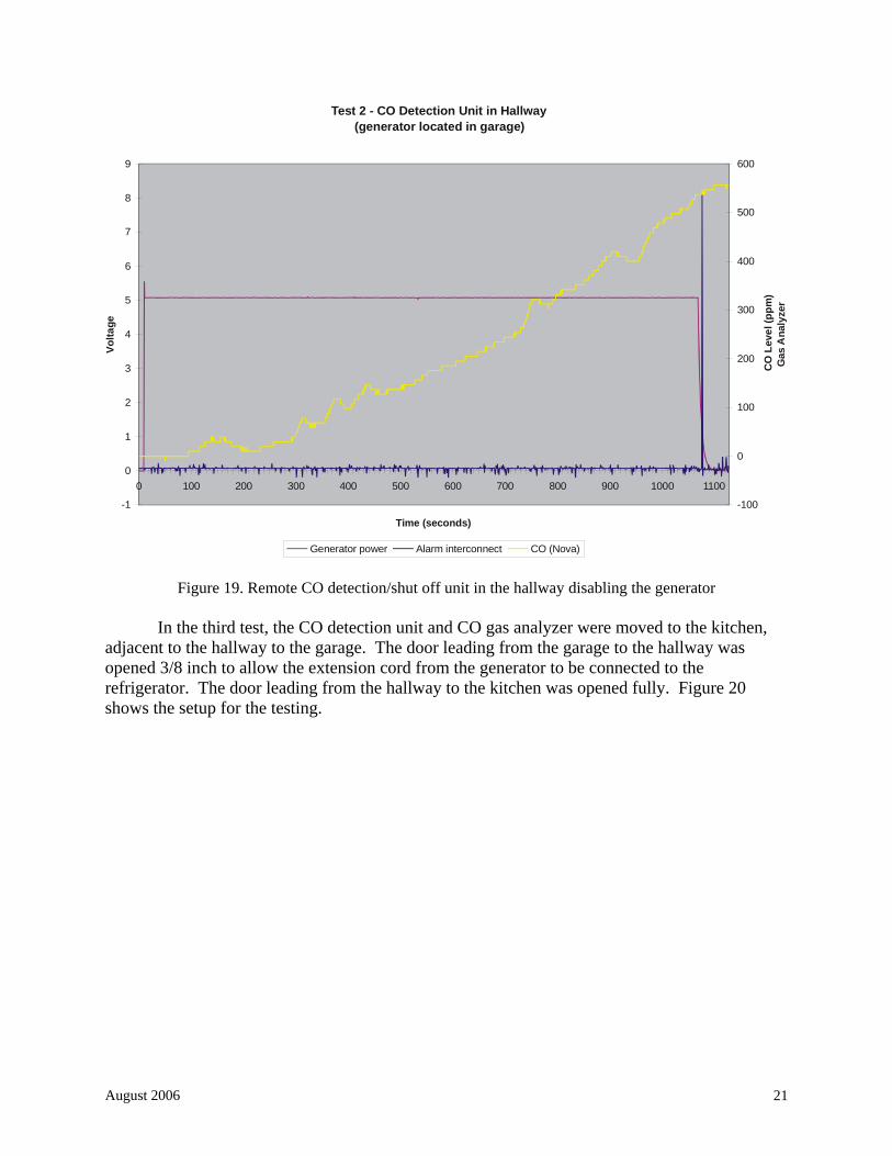
Figure 18. Test 2 set-up with remote CO detection/shut off unit in the hallway The start button on the CO detection unit was depressed, which enabled starting of the generator. The generator was pull-started successfully. After about 17 minutes, the gas analyzer measured approximately 532 ppm in the hallway. At this time, the CO detection unit began to alarm, which caused the unit to transmit a signal to the receiver unit. The receiver unit received the signal and the generator stalled and shut off, as shown in Figure 19. In examining Figure 19, the graph makes it appear as though the generator began to shut off before the CO detection unit triggered the transmitter. This was because the digitizing system sampling rate of 1 second was not frequent enough to capture the first pulse signal from the CO detection unit. The CO detection unit’s LED indicated 520 ppm when the generator was shut off.
The garage and exterior doors were opened and CO levels were allowed to drop to near
zero before the operator re-entered the structure. The gas analyzer was zeroed before the next test.
August 2006 21
Test 2 - CO Detection Unit in Hallway(generator located in garage)
-1
0
1
2
3
4
5
6
7
8
9
0 100 200 300 400 500 600 700 800 900 1000 1100
Time (seconds)
Volta
ge
-100
0
100
200
300
400
500
600
CO
Leve
l(pp
m)
Generator power Alarm interconnect CO (Nova)
Gas
Ana
lyze
r
Figure 19. Remote CO detection/shut off unit in the hallway disabling the generator In the third test, the CO detection unit and CO gas analyzer were moved to the kitchen,
adjacent to the hallway to the garage. The door leading from the garage to the hallway was opened 3/8 inch to allow the extension cord from the generator to be connected to the refrigerator. The door leading from the hallway to the kitchen was opened fully. Figure 20 shows the setup for the testing.

August 2006 22
Closed
Partiallyclosed
Garage doorclosed
Garage doorclosed
CO
Generator withShut-off Unit
Extension cordto refrigerator
To living area
To basement
To b
asem
e nt
open
both units approximately3.5 ft from the floor
Garage doorclosed
To foyer
To diningroom
Kitchen
Open to family room
Refigerator
CO Detection Unit
Gas Analyzer
Data Acquisition System
Distance 5 feet from the exterior door
closed
To second floor
Figure 20. Test 3 set-up with remote CO detection/shut off unit in the kitchen
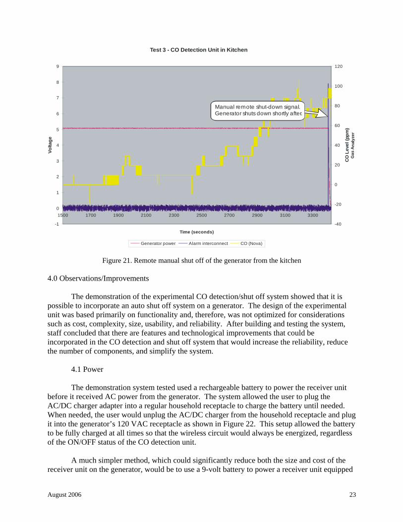
The start button on the CO detection unit was pressed, which enabled starting of the generator. The generator was pull-started successfully. After almost 1 hour of generator operation, the CO gas analyzer measured 90 ppm in the kitchen. Note that the CO levels in the kitchen did not reach the threshold level for the alarm to activate. To test the remote manual shut off of the generator, the test button was pressed on the CO detection unit, causing it to transmit a shut off signal. The receiver unit received the signal, causing the generator to shut off as shown in Figure 21. The LED display on the CO alarm displayed 82 ppm when the generator had shut off. The remote manual shut off of the generator allowed the tester to stop the generator without entering the garage which, based on earlier testing, most likely contained elevated levels of CO. In the first test, the CO levels in the garage measured over 700 ppm in 8 minutes. For this test, the generator was operating for almost 60 minutes before being shut off. The actual CO level in the garage was not measured.
As demonstrated in test 3, the remote shut off device could be very beneficial in that it
could allow the user to shut the generator off remotely (without having the user enter the area near the generator, which may contain high levels of CO).
August 2006 23
Test 3 - CO Detection Unit in Kitchen
-1
0
1
2
3
4
5
6
7
8
9
1500 1700 1900 2100 2300 2500 2700 2900 3100 3300
Time (seconds)
Volta
ge
-40
-20
0
20
40
60
80
100
120
COLe
vel(
ppm
)
Generator power Alarm interconnect CO (Nova)
Manual remote shut-down signal. Generator shuts down shortly after.
Gas
Ana
lyze
r
Figure 21. Remote manual shut off of the generator from the kitchen
4.0 Observations/Improvements
The demonstration of the experimental CO detection/shut off system showed that it is possible to incorporate an auto shut off system on a generator. The design of the experimental unit was based primarily on functionality and, therefore, was not optimized for considerations such as cost, complexity, size, usability, and reliability. After building and testing the system, staff concluded that there are features and technological improvements that could be incorporated in the CO detection and shut off system that would increase the reliability, reduce the number of components, and simplify the system.
4.1 Power The demonstration system tested used a rechargeable battery to power the receiver unit
before it received AC power from the generator. The system allowed the user to plug the AC/DC charger adapter into a regular household receptacle to charge the battery until needed. When needed, the user would unplug the AC/DC charger from the household receptacle and plug it into the generator’s 120 VAC receptacle as shown in Figure 22. This setup allowed the battery to be fully charged at all times so that the wireless circuit would always be energized, regardless of the ON/OFF status of the CO detection unit.
A much simpler method, which could significantly reduce both the size and cost of the
receiver unit on the generator, would be to use a 9-volt battery to power a receiver unit equipped

August 2006 24
with an ON/OFF power switch. The 9-volt battery would be used to power the receiver unit until the generator started. The usage life of the battery would be similar to its shelf life because of the short duration of the usage period just prior to generator start-up. Typically, an alkaline battery can have a 5-year shelf life, which may vary with extremes in temperature.
Household receptacle
Stand-By Mode
User wants tostart generator(example - loss of household power)
User startsgenerator
AC/DC Charger
Generator Start-Up Mode
Receiver is poweredby battery back-up
AC/DC Charger
Generator Running Mode
Generator withShut-off Unit
Back-up batterybeing charged Receiver is powered
by generator andrecharges batteryback-up
AC/DC Charger
Figure 22. Powering the receiver unit
4.2 Relays The demonstration system had six standard relays available and an additional high
current relay. The six relays were programmed and controlled by the wireless circuitry. Each relay could be programmed separately. The relays could be programmed to be momentary, latched, validity**, 30-second timed, 1-minute timed, 5-minute timed, 20-minute timed, or strobed (repeated ON/OFF). Each relay could be used normally open (N.O.) or normally closed (N.C.) and was rated for 3 amps at 12 VDC. The shut off system used only two of the six relays on the circuit board. The two relays were used to control the high current relay, which was rated at 7 amps at 30 VDC or 10 amps at 125 VAC.
The number of relays needed can be reduced, and it is possible the high current relay
could be eliminated. The six relay circuit board could also be reduced to one or two relays depending on the programming capabilities of the relay circuit. Reducing the number of relays would also drastically reduce the size and cost of the receiver unit.
4.3 CO Detection Unit A residential CO alarm was integrated with a wireless transmitter. The CO alarm used
AC power with battery back-up. In the testing, only the battery back-up power source was used. Since the alarm was originally designed for household plug-in as the primary power, the alarm had an LED display, which required a significant amount of power. Most battery-only powered CO alarms use an LCD display to help minimize current usage.
** Only ON when pressed and OFF when released.

August 2006 25
4.4 Supervised System
The demonstration system utilized an unsupervised wireless system. The shut off unit on the generator and the remote CO detection unit did not incorporate an additional check for communication integrity. The disadvantage of such a system is that it would allow a user to disable the CO detection unit after starting a generator, thus leaving occupants unprotected in the event of a CO build-up.
A supervised system would allow each of the units, CO detection and shut off units, to
monitor each other. The CO detection and shut off units would each have a transmitter and receiver, or a transceiver. If the shut off unit on the generator did not receive a periodic check signal from the CO detection unit, the shut off unit would disable the generator. If the CO detection unit did not receive a periodic check signal from the shut off unit, the CO detection unit would sound an alarm, indicating that it was out of range or the shut off unit had malfunctioned.
4.5 Wireless Range
The maximum range tested for the demonstration unit was approximately 50 feet through
one wall or door. The minimum required reliable wireless range between the CO detection unit and generator would need to be determined to ensure that the CO detection unit and generator work as intended for consumers.
4.6 Feed-Back Indicators
The demonstration unit did not contain any feed-back indicators to indicate that the system was operating correctly. Indicator lights on the shut off unit would allow the user to know the system status.
4.7 Self-Check
The demonstration unit did not conduct a self-check of the circuitry. Similar to a supervised system for wireless communication, the self-check would determine that the remainder of the circuitry in the CO detection and shut off units was functioning.

August 2006 26
4.7.1 CO Detection Unit Self-check the CO sensor sensitivity A periodic check of the CO sensor sensitivity to determine if the sensor has become more or less sensitive than manufacturer specifications would help prevent the CO alarm from nuisance alarming or not alarming when elevated levels are present. Low battery check A low battery check in the CO alarm unit would allow the user to change the battery before the system becomes nonfunctional. Transceiver circuitry is functioning
A self-check of the transceiver circuitry would determine if the circuitry is functioning correctly. 4.7.2 Shut Off Unit Self-check the relay circuitry A self-check of the relay circuitry would determine if the circuitry is functioning correctly. Low battery check A low battery check in the receiver unit would allow the user to change the battery before the system becomes nonfunctional. Transceiver circuitry is functioning A self-check of the transceiver circuitry would determine if the circuitry is functioning correctly. Continuity with the manual ON/OFF switch A continuity check of the manual ON/OFF switch would determine if the receiver unit is connected to the generator and has not been disabled or bypassed.
4.8 Cost
Off-the-shelf components used in the demonstration included an AC-powered CO alarm
with battery back-up, which retails for approximately $52. The CO alarm cost would be lower if it was only battery powered and contained an LCD instead of an LED display. The off-the-shelf

August 2006 27
wireless transmitter and receiver system cost approximately $100 (retail). The system contained more features than were actually required in the demonstration unit and more features than would be required in a production unit. For example, the unit was programmable, which was a useful feature for prototyping but unnecessary for production units. Additionally, although the demonstration unit contained six relays, only two were used in the system. This number could probably be further reduced to one relay with careful circuitry design and programming. The high current relay used in these tests cost approximately $12 (retail), which could have been omitted in the design. For the circuitry and the other associated hardware discussed above, the engineering staff estimates that a production unit could add an additional $100 to the cost of a portable generator. The average cost of a retail CO alarm is approximately $30 and the wireless circuitry would be an additional $50 to $70. The additional cost would depend on many factors, such as the manufacturer’s approach and previous experience in using wireless technology, technique for interfacing the shut-off circuitry with the generator, and type of CO alarm. In addition, there could be additional costs in producing a final product that makes the system reliable, consumer friendly, and other factors that were not examined in this demonstration. 5.0 Summary
In recent years, the proliferation and increased availability of portable generators at the consumer level have resulted in an increase in the number of carbon monoxide (CO) related deaths. To help mitigate the CO hazards associated with the use of portable generators, the CPSC staff successfully demonstrated a concept to incorporate an auto shut off device on a portable gasoline-fueled engine generator that activates when elevated CO levels are detected in the home. A method of monitoring CO levels at a single location away from the generator was explored. If elevated CO levels are detected in the home, an auto shut off device can disable the generator.
A demonstration system was designed and built to evaluate the concept of shutting off a generator from a remote location when elevated levels of CO are detected. For the demonstration system, a wireless transmitter was incorporated into a CO alarm that was used as the initiating device to signal a shut off of the generator. A wireless receiver and relays were used to shut off the generator.
Several tests were conducted to determine the functionality of the CO detection and shut
off system. Testing was conducted using the test button on the CO detection unit with the receiver unit mounted on the generator. Several tests were conducted to allow the CO detection unit to detect elevated levels of CO and shut off the generator remotely. In all the tests, the generator shut off when the CO detection unit transmitted a shut off signal. The CPSC staff viewed this program as a successful demonstration of the CO detection/automatic generator shut off concept.
The study was limited to proof-of-concept and did not consider issues such as life
expectancy, reliability, usability, and environmental conditions. All of these factors would need to be considered in developing a remote CO detection/shut-off system for portable generators for consumer use.

August 2006 28
No Text on This Page

December 2005 DRAFT A
APPENDIX A
Standard Operating Procedures for Assuring Minimum Carbon Monoxide Exposure During Demonstration of
a Remote Carbon Monoxide Detection Shut Off Device for a Portable Generator

DRAFT December 2005
No Text on This Page

December 2005 DRAFT A-1
Standard Operating Procedures
for Assuring Minimum Carbon Monoxide Exposure During Demonstration of a Remote
Carbon Monoxide Detection Shut Off Device for a Portable Generator
Prepared by Arthur S. Lee
Electrical Engineer
Division of Electrical Engineering
U.S. Consumer Product Safety Commission
August 2005
Version 2

Page 2 of 7 Version 1 Date : August 2005
Standard Operating Procedures For Assuring Minimum Carbon Monoxide Exposure Title: Guidelines and Procedures for Demonstration of a Remote Carbon
Monoxide Detection Shut Off Device for a Portable Generator
DRAFT December 2005 A-2
1.0 PURPOSE:
The purpose of this document is to specify appropriate procedures and safeguards for test personnel to follow to protect them from exposure to potentially-harmful concentrations of carbon monoxide during testing of a prototype remote CO detection/ automatic shut off system installed on a portable generator running indoors in an actual residence. The nature of the testing is to intentionally reproduce an inappropriate (albeit foreseeable) application of a portable gasoline-fueled electric generator (operating it indoors) to evaluate the effectiveness of the prototype system. 2.0 DEFINITIONS:
For purposes of this document, the following definitions apply: Standard Operating Procedures
The recognized, acceptable criteria which serve as support for methods or manners of fulfilling a function or functions.
CO
Carbon Monoxide. The CO in this testing will be one of the components of the exhaust gasses produced by the portable generator.
Portable Generator
The gasoline-powered engine-driven, electric generator that was outfitted with a radio-frequency (RF) receiver controlling an engine shut off device.
Remote Carbon Monoxide Detection/Shut Off Unit
The carbon monoxide detection unit that was outfitted with an RF transmitter to send a signal to the receiver unit on the generator. PPM Parts per million. Units representing the concentration of carbon monoxide. Manual Remote Shut Off Device A hand-held transmitter that can be used to shut off the generator from a location where accumulated CO is below hazardous levels.

Page 3 of 7 Version 1 Date : August 2005
Standard Operating Procedures For Assuring Minimum Carbon Monoxide Exposure Title: Guidelines and Procedures for Demonstration of a Remote Carbon
Monoxide Detection Shut Off Device for a Portable Generator
December 2005 DRAFT A-3
Gas Analyzer A portable unit that measures the level of carbon monoxide with an accuracy better than 1% of the instrument’s full scale based on a 0-2000 ppm range and a response time of at most 30 seconds for a 90% step change; the unit must also be capable of remote monitoring.
3.0 SCOPE:
The testing is to demonstrate the prototype CO detection/shut off unit as incorporated with a generator by detecting CO and remotely shutting off the generator in an actual residence. The elevated levels of CO are to be generated by the portable generator in a confined space, such as a garage. The set-up and configuration of the testing to be conducted are for test purposes only and are inconsistent with correct and safe operation of a portable generator.
4.0 GUIDELINES:
Monitored CO levels The level of CO in the test structure shall be monitored from the exterior of the test structure by two methods (residential CO alarm and a CO gas analyzer). The level of CO in the test structure shall be monitored in two areas of the test structure by residential CO alarms. Operator(s) The operator(s) shall be at a minimum of 20 feet from the test structure during testing. The data acquisition system shall be located a minimum of 20 feet from the exterior of the test structure. The instrumentation and operator(s) shall be upwind or adjacent to the test structure during testing. DO NOT TEST if the instrumentation and operator(s) are downwind of the test structure. Reentry The operator(s) shall reenter the test structure only when the CO concentration readings from both monitors are below 5 ppm. The operator(s) may enter CO monitor areas for less than 15 seconds if the CO levels are below 95 ppm. This 15-second period for concentrations below 95 ppm is within the OSHA PEL, NIOSH REL, and AGGIH TLV exposure limits for CO, as defined below.

Page 4 of 7 Version 1 Date : August 2005
Standard Operating Procedures For Assuring Minimum Carbon Monoxide Exposure Title: Guidelines and Procedures for Demonstration of a Remote Carbon
Monoxide Detection Shut Off Device for a Portable Generator
DRAFT December 2005 A-4
OSHA PEL The current Occupational Safety and Health Administration (OSHA) permissible exposure limit (PEL) for carbon monoxide is 50 parts per million (ppm) parts of air (55 milligrams per cubic meter (mg/m(3))) as an 8-hour time-weighted average (TWA) concentration [29 CFR Table Z-1]. NIOSH REL The National Institute for Occupational Safety and Health (NIOSH) has established a recommended exposure limit (REL) for carbon monoxide of 35 ppm (40 mg/m(3)) as an 8-hour TWA and 200 ppm (229 mg/m(3)) as a ceiling [NIOSH 1992]. ACGIH TLV The American Conference of Governmental Industrial Hygienists (ACGIH) has assigned carbon monoxide a threshold limit value (TLV) of 25 ppm (29 mg/m(3)) as a TWA for a normal 8-hour workday and a 40-hour workweek [ACGIH 1994, p. 15]. Remote Shut Off The generator shall be capable of being remotely shut off by two methods. One method must be a hand-held transmitter worn by the operator(s). Effects of Carbon Monoxide
The operator(s) shall be familiar with the symptoms and effects of CO on a
person. Signs and symptoms of acute exposure to carbon monoxide may include headache, flushing, nausea, vertigo, weakness, irritability, unconsciousness, and in persons with pre-existing heart disease and atherosclerosis, chest pain and leg pain. (U.S. Department of Labor, Occupational Safety & Health Administration) Generator The gas tank will be filled with a maximum of ½ gallon of gas, limiting the run time to approximately 1 hour (7 gallons for 14 hours of operation) Test Structure All doors to the test structure not visible by the operator(s) shall be locked to prevent persons from entering the test structure. The operator(s) shall carry keys to unlock any of the doors on the test structure.

Page 5 of 7 Version 1 Date : August 2005
Standard Operating Procedures For Assuring Minimum Carbon Monoxide Exposure Title: Guidelines and Procedures for Demonstration of a Remote Carbon
Monoxide Detection Shut Off Device for a Portable Generator
December 2005 DRAFT A-5
5.0 PROCEDURES:
5.1 Initial Verification of Hardware Operation
The operator(s) shall verify that the test instrumentation and prototype test units are operational. The gas analyzer shall not have a certification older than 5 years. The wireless transmission of the shut off signal from the CO detection unit to the generator shall be tested by using the test button on the CO detection unit. The manual handheld transmitter for generator shut off shall be tested prior to any testing.
5.2 Location of the CO source (generator)
The portable generator shall be located in a test structure that allows easy ventilation of the test room, such as a garage. The test room or garage shall be equipped with remote ventilation, such as wireless garage door openers and fan(s).
5.3 Location of the CO detection units
The CO detection unit shall be located in areas of the test structure that provide accurate monitoring of CO levels in areas where operator(s) ingress and egress would result in potential exposures.
5.4 Pre-Testing Safety Checklist
a. Gas analyzer reading of CO level in the structure is below 5 ppm b. CO detection unit reading is zero c. Generator gasoline tank filled with maximum of ½ gallon of gasoline d. Instrumentation and data acquisition ready e. Verify no person in the test structure f. Zero gas analyzer before each test
5.5 Post Testing Safety Checklist
a. Generator has shut off b. Stop data acquisition c. Ventilate the test structure remotely d. Monitor CO levels in the test structure

Page 6 of 7 Version 1 Date : August 2005
Standard Operating Procedures For Assuring Minimum Carbon Monoxide Exposure Title: Guidelines and Procedures for Demonstration of a Remote Carbon
Monoxide Detection Shut Off Device for a Portable Generator
DRAFT December 2005 A-6
6.0 INSTRUMENTATION AND EQUIPMENT SET-UP:
The following is a list of instrumentations to be used in the testing:
a. Residential Carbon Monoxide Alarm (AC powered with 9-volt battery back-up)
b. NOVA Gas Analysis Equipment (Model 310WP) c. Data Translation (Model DT9834) d. Dell Laptop Computer (Model 5150) e. Fluke Current Probe (Model 80i-110s) f. Street Smart Technologies Wireless Automator (Model WA6R) g. Portable Generator (5250 watt)
The following diagram is an illustration of the test set-up for testing the CO detection/shut off system and the portable generator.
Closed
Ventilation Ventilation Ventilation
CO
COCO
Data Acquisition System
Remote Ventilation System
Generator withShut-off Unit
CO Gas Analyzer
Display of COLevels
20 feet minimum
CO Detection Unit
Residential COAlarms
Viewing window of instrumentation
Test Structure

Page 7 of 7 Version 1 Date : August 2005
Standard Operating Procedures For Assuring Minimum Carbon Monoxide Exposure Title: Guidelines and Procedures for Demonstration of a Remote Carbon
Monoxide Detection Shut Off Device for a Portable Generator
December 2005 DRAFT A-7
7.0 EMERGENCY PROTOCOL:
Intervention for CO Poisoning 1. At first signs of CO poisoning symptoms, shut off the generator 2. Go or move victim to a well-ventilated area 3. Dial 911