Igniters meetup - Network hacking 50 years of networking wisdom with mike macedonio
Upload
trinhnguyetCategory
view
217download
1
TECHNICAL REPORT ARB RL-TR-02398
FLAME TEMPERATURES AND INTERNAL
PRESSURES OF PYROTECHNIC
IGNITERS USED IN LIQUID
PROPELLANT GUN FIRINGS
Guenter Klingenberg John D. Knapton Douglas Taylor I rvi n C. Stobie
March 1982
FiLE Copy
US ARMY ARMAMENT RESEARCH AND DEVELOPMENT COMMAND BALLISTIC RESEARCH LABORATORY
ABERDEEN PROVING GROUND, MARYLAND
Approved for public release, distribution unlimited.
Destroy this report when it is no lonaer needed. Do not return it to the originator.
Secondary distribution of this report by originatina or sponsorina activity is prohibited.
Additional copies of this report may be obtained from the National Technical Information Service, U.S. Department of Commerce, Sprinafield, Virginia 22161.
The findings in this report are not to be construed as an official Department of the Army position, unless so designatec by other authori:ed docuoents.
Tlw :111~ ,•;' :r'tlu*i >ltDIII&I .)r 'IIIPIII{actla'f'N' 'lallltD !11 ti1f.J ·'l!~·or•t W•'tl >J.)t •. un4t:'tw~"' !ndoN4fiWPit of' an11 ~l'Oial ~f'C"ir • ..!t,
Ui-JCLASSIFIED SECURITY CLASSIFICATION OF THIS PAGE (When Dare l!ntered)
REPORT DOCUMENTATION PAGE READ INSTRUCTIONS BEFORE COMPLETING FORM
1. REPORT NUMBER ,2. GOVT ACCESSION NO. 3. RECIPIENT'S CATALOG NUMBER
Technical Report ARBRL-TR-02398 4. TITLE (lind Subtitle)
FLA/IlE THIPER,HURF.S ANn INTERNAL PRESSURES OF PYROTECHNIC LGNITtRS USED lN LIQU!D PROPELLANT GU:\ FIRINGS
Guenter Klingenberg*, John D. Knapton, Douglas Taylor** and Irvin C. Stobie
ti. ~:R~~~Ifi~.M!ntT 1~~~~fcWD&A~Ne\opment Command U.S. Army Ballistic Research Laboratory ATTi-i: DRDAR-BLI Aberdeen Provino Ground, /110 21005 II. CONTROLLING OFFICE NAME AND ADDRESS
U.S. Army Armament Research & Development Command U.S. Army Ballistic Research Laboratory (DRDAR-BL) Aberdeen Proving Ground, :Tl 21005
4"4. lot\.»nft.,,.,.;;.,& AG€N6Y NAN'£ 6 MlOWt!:SS(Ifttnte..-11 from Controllln' Office)
t· DISTRIBUTION STATEMENT (of tht. Report)
5. TYPE OF REPORT 4 PERIOD COVERED
5. PERFORMING ORG. REPORT NUMBER
8. CONTRACT OR GRANT NUMBER(•)
10. PROGRAM ELEMENT, PROJECT, TASK AREA 4 WORK UNIT NUMBERS
1Ll62618AH80
12. REPORT DATE
~~arch 1982 13. NUMBER OF PAGES
72 15. SECURITY CLASS. (of thle report)
Unclassified IS e. DECL ASS I FICA TION/ DOWNGRADING
SCHEDULE
Approved for public release; distribution unlimited.
17. DISTRIBUTION STATEMENT (of the ebalrecl llnlered In Block 20, It different from Report)
18. SUPPLEMENTARY NOTES
*Fraunhofer-Institut Fuer Kurzzeitdynamik, Ernst-Mach-Institut Abteilung Fuer Ballistik (EMI-AFB), Hauptstrasse 18, 7858 Weil am Rhein, West Germany
**Dept. of Chemistry, University of Illinois, Urbana,Illinois ~----~~--~~~~~--------~~~------~~~~~~~--~~--------------------------------~ ; 19 . KEY WORDS (Continue on rever•• aide If nace .. ery ..,d Identify by block number)
Ignition Temperature Pressure Pyrotechnic Igniter Liquid Propellant
20. All$~ ACT (CaatiDu• - ,.,.r_ elo It .....--..q- lden.tlfr by block nUDtbet')
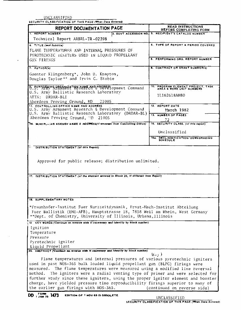
(r ,, J ) Flame temperatures and internal pressures of various pyrotechnic igniters
used in past NOS-365 bulk loaded liquid propellant gun (BLPG) firings were measured. The flame temperatures were measured using a modified line reversal method. The igniters were a radial venting type of primer and were selected for further study since these igniters, using the proper igniter element and booster charge, have yielded pressure time reproducibility firings superior to many of the earlier gun firings with NOS-365. (continued on reverse side)
DO FORM IJAN7.i 1473 EDfTION OF I NOV 115 IS OBSOLETE
UNCLASSIFIED SECURITY CLASSIFICATION OF THIS PAGE('"'- Data Entered)
U;\C 1.-\SS I FI ED
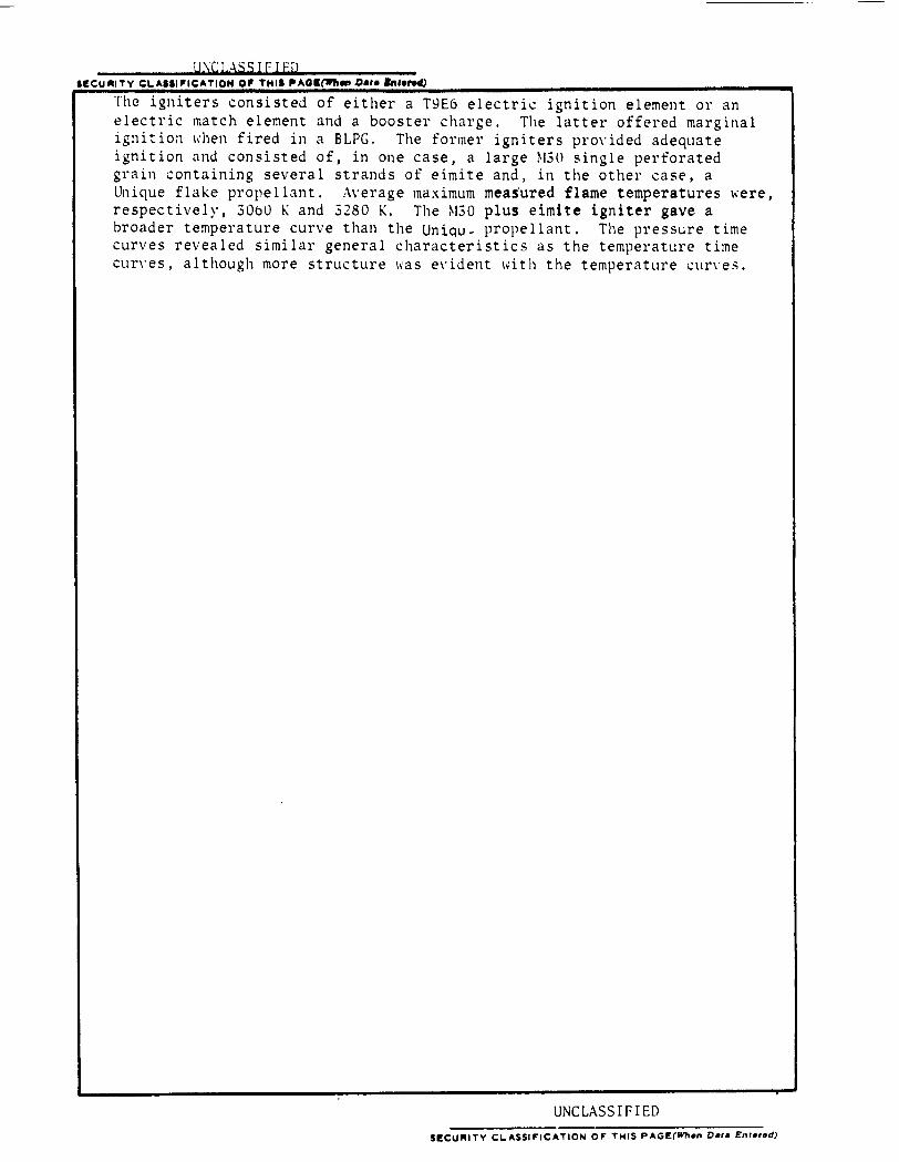
The igniters consisted of either a T9E6 electric ignition element or an electric match element and a booster charge. The latter offered marginal ignition ~hen fired in a BLPG. The former igniters provided adequate ignition and consisted of, in one case, a large ~130 single perforated grain containing several strands of eimite and, in the other case, a Unique flake propellant. Average maximum measured flame temperatures 1•ere, respectivelr, 30o0 !\ and 3280 !\. The ~130 plus eimite igniter gave a broader temperature curve than the Uniqu. propellant. The pressure time curves revealed similar general characteristics as the temperature time cur\'es, although more structure ll'as e\·ident 1dth the temperature cun·es.
UNCLASSIFIED SI:CU .. ITY CL.ASSII"ICATION 01" THIS F'AGE(If'hen Data Entered)
TABLE OF CO\TE~TS
LIST OF ILLUSTRATIO~S
LIST OF TABLES
I. I:\TRODUCTIO~
II. PROCEDURE A\D RESULTS
Pyrotechnic: Igniters
Time Integrated Flame Output
Pressure Data .
Flame Emission
Temperature Data
III. DISCUSSIO~S AND CO\CLUSIO~S
REFERE~CES
:\PPE\DIX A
:\PPE\DIX B
APPE:-.iDIX C
APPE~DIX D
APPE\DIX E
APPE\DIX F
APPENDICES REFERENCES
DISTRIBUTION LIST . .
3
Page
5
7
9
11
11
11
16
19
23
24
27
29
35
43
47
53
61
72
Figure
l
2
5
B-l
B-~
B-3
B-4
B-5
B-6
B-8
B-9
B-10
B-11
C-l
LIST OF ILLUSTRATIO~S
Schematic of Venting Primer
Time Integrated Pictures of Igniter Output
Time Integrated Pictures of Igniter Output. The Electric Igniter Element in all Cases was T9E6
Primer Closed Chamber
Optical Set-up for Studying Flame Emission and Line Reversal . . . .
T9E6 Igniter and a Booster Charge of ~130 and Eimite
T9E6 Igniter and a Booster Charge of ~GO and Eimite
T9E6 Igniter and a Booster Charge of ~GO and Eimite
T9E6 Igniter and a Booster Charge of Unique
T9E6 Igniter and a Booster Charge of Unique
T9E6 Igniter and a Booster Charge of Unique
T9E6 Igniter and a Booster Charge of Unique
T9E6 Igniter and a Booster Charge of Unique
T9E6 Igniter and a Booster Charge of Unique
Electric Match Igniter and a Booster Charge of Unique
Electric ~~tch Igniter and a Booster Charge of Unique
Plot of Ts and T1
vs Lamp Current
Page
12
13
17
21
37
37
38
38
39
39
40
40
41
42
46
0-l Round 147 - Photomultiplier Tube Signal with Chopper 49
D-2 Round 152 - Photomultiplier Tube Signal with Chopper 4. 5 kHz Chopper . . . SO
D-3 Round 153 - Photomultiplier Tube Signal with Chopper 4. 5 kHz Chopper . 51
5
LIST OF ILLUSTRATIONS
Figure Page
E-1 Round 155 - !-13G and Eimite Photo-, multiplier Tube Outputs 55
E-2 Round 162 - Igniter Unique 100 . 56
E-3 Round 167 - Igniter Unique 100 Photomultiplier Tube Outputs . . . . . . . . . . . . . . . . . . ... 57
E-4 Round 168 - Igniter Unique 100 Photomultiplier Tube Outputs . . . . . . . . . . . . . . . . . . . . 58
E-5 Round 118- Electric Hatch (~1103) 1 Pnotomul tiplier Tube Outputs . . . . . . . . . . . . . . . . . . 59
F-1 Round 155 - H30 plus Eimite, Temperature vs Time . 63
F-2 Round 162 - Igniter Unique 1001 Temperature vs Time . . 64
F-3 Round 167 - Igniter Unique 100 Temperature . . . . . 65
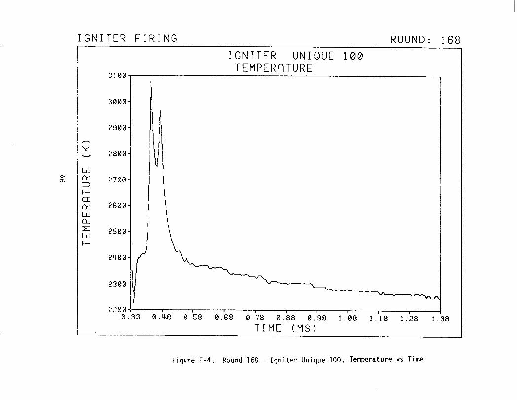
F-4 Round 168 - Igniter Unique 100 Temperature . 66
F-5 Round 118 - Electric ~1atch rmo31 I TemPerature vs Time . 67
6
LIST OF TABLES
TABLE Page
1. SU~L\L\RY OF PRESSURE DATA OBT.U:-.;ED FRml TESTS 11/ITH THE PRIMER CH.\HBER • . • . • • • . • . . • • , . • . . 18
2. SU~L\1.\RY OF PRESSURE DATA OBTAI\ED FRml TESTS 1\'ITH THE PRI~ER CH»IBER. ALL TESTS WERE IG:-.;ITED USI\G A\ ELECTRIC ~lATCH • • • • • • • . . . . . . . • 20
_,. SU~IH.\RY OF ~l.\XHIU~I IG!\ITER THIPERATURES 25
A-1 PROPERTIES OF m03/M203 ELECTRIC ~lATCH 31
A-2 T9E6 ELECTRIC IG:--<ITIO:--.l ELHIE\T . 32
A-3 PROPERTIES OF THE BOOSTER CHARGE USED 1\ THE RADIALLY H\Til\G PYROTECH~IC PRHIERS . • • . • . . . 33
C -1 CHARACTERISTICS OF THE TU\GSTE\ R I BBO:-.; F ILA~IE\T LA~IP
AT 655 ~~I . . . . . 45
7
I. INTRODUCTION
The lack of quantitative ignition design criteria in liquid propellant gun firings requires the development of appropriate diagnostics to study the igniter output. The initial energy distribution in the propellant during the ignition phase is one of the main unknowns during propellant ignition. Data on the initial energy distribution is required to understand fundamental mechanisms during liquid propellant ignition. A first step towards this goal is the measurement of the igniter output in terms of pressure, flame- temperature and gas velocity. Past measurements on the output of pyrotechnic igniters consisted primarily of pressure data.l,2 To completely characterize the energy output of pyrotechnic igniters requires information on both the gas phase properties, i.e., the pressure, velocity and temperature distribution during venting and also on the particle properties during the multiphase flow. This paper addresses a diagnostic approach for measuring the igniter output, when venting at room conditions, in terms of flame temperature. Pressure time data obtained earlier using some of the same igniters are also included for comparison with the temperature data.
Bulk loaded liquid propellant gun firings have demonstrated the importance of the ignition phase as one of the critical elements necessary for achieving ballistic control.2,3 Two conditions are considered necessary: the igniter must be reproducible and must have the proper energy output characteristics to successfully ignite the propellant to
1J. D. Knapton, I. C. Stobie and R. H. Comer, "Pyrotechnic Primer Design for Liquid Propellant Guns," 13th JANNAF Combustion Meeting, CPIA Publication No. 281, Vol. I, Applied Physics Laboratory, Silver Spring, p. 18? (19?6).
2J. D. Knapton and I. C. Stobie, "Conditions Required for Controlling Breech Pressure During a Bulk Loaded Liquid Propellant Gun Firing (UJ," 16th JANNAF Combustion Meeting, CPIA Publication No. 308, Vol. IV, Applied Physics Laboratory, Silver Spring, p. 51 (19J9).
3J. D. Knapton and I. C. Stobie, "Bulk Loaded Liquid Propellant Guns: What Can be Expected in TeY'ms of Pressure Reproducibility?", Journal of Ballistics, Vol. III, p. 615 (1980).
9
'd 4 d 'bl d · · 2 5- 7 avo1 pressure waves an , poss1 y, secon ary 1gn1t1on s1tes, ' The development of a pyrotechnic igniter to achieve these conditions has proven difficult. For example, an igniter using a T9E6 and a booster charge of Unique flake propellant yielded excellent reproducibility,l,S yet the gun firings yielded a greater level of variability than a primer using a larger web propellant, containing M30 and eimite, but which had a lower level of reproducibility,9 It had been speculated that the igniter with the Unique flake booster charge yielded the relatively poor ballistic reproducibility due to an unnecessarily high rate of energy output which generated large pressure waves in the chamber and, possibly, uncontro~lgd ignition sites due to ignition at bubbles from adiabatic compression. ' - 7 On the other hand, the gun firings using the igniter with the M30 and eimite yielded breech pressure time traces with similar general features and a variation in the standard deviation of the peak breech pressure of 6.5%. This level of reproducibility is encouraging, especially when the
4A. R. Guzdar, S. S. Rhee and A. J. Eriokson, "ModeLing Studies of the Liquid ProopeUant Gun," Foster-i1i Uer Assooiates, Ina., BaUistio Researoh Laboratory Contraot Report No. 5? (19?1).
5N. A. Messina, L. S. Ingram, Preston E. Camp, M. Ben Reuben and M. SummerfieLd, "Corrrpression-Ignition Sensitivity Studies of Liquid PropeUants for' Guns," Prinoeton Combustion ReseaT'oh LaboT'atories, Ina., RepoT't No. PCRL-FR-?9-004 (19?9}.
6v. M. BoyLe and E. A. 0 'Lecaoy, "Ignition of NOS-365 Liquid ProopeUant Containing an Air' BubbLe Under' SimuLated BT'eeoh PressuT'ization Conditions, 11 USARRADCOM TeohnioaL RepoT't ARBRL-lf'R-02236 (1980).
? J. Mandzy, K. SohaefeT', J. Knapton and W. MOT'T'ison, "ProgT'ess RepOT't on CompT'ession Ignition Sensitivity of NOS-365 Under' Rapid PropeLLant FilL Conditions," l?th JANNAF Combustion Meeting, CPIA PubLication No. 329, VoL. II, AppLied Physios LaboT'atoT'y, SiLveY' SpT'ing, Md., p. 309, (1980).
8J. D. Knapton, I. c. Stobie and R. H. ComeT', "PyT'oteohnio Ignition Systems Used in a Medium CaLiber' BuLk Loaded Liquid ProopeUant Gun," 19?8 JANNAF PropuLsion Meeting, CPIA Publication No. 293, VoL. I, AppLied Physios LaboT'atory, SilveY' Spring, p. 5?9 (19?8}.
9J. D. Knapton, I. C. Stobie, R. H. ComeT', B. Bensinger' and D. HenT"y, "ResuLts fT'om a Study on the Ignition of Liquid ProopeUant Rounds in a Medium CaUbeT' Gun Using a RadiaL Venting Primer','' USARRADCOM Technioal RepoT't (beinq T'eVieuJed} • 198 2.
10
particular shape of the breech pressure time curve was associated with an increase in ballistic efficiency.lO
Since past liquid propellant igniter studies have not been adequately characterized, it was considered that a study of the igniter temperature time output might aid in developing further empirical guidelines and assist in providing more general ignition requirements necessary for modeling the gun firings. Before describing the experimental details, a review of the relevant pyrotechnic systems used for ignition in past NOS-365 BLPG gun firings9,10 will be given.
II. PROCEDURE AND RESULTS
A. Pyrotechnic Igniters
Th h . . . 9,10 d . h . h . F' 1 e pyrotec n1c 1gn1ter use 1n t e tests 1s s own 1n 1gure . Information on the properties of the ignition elements and the propellant used in the igniters is given in Appendix A. An electric igniter element (T9E6 or electric match) is discharged at the igniter base and together with a booster charge develops sufficient pressure to force a piston forward which uncovers holes in the wall of the igniter. Ideally, the piston displacement uncovers the holes simultaneously as well as integrating the early fluctuations in combustion. Two versions of the radially venting igniter were used. In one igniter, referred to as PR, the igniter consisted of a booster charge (usually ~130 and eimite). In a later igniter, referred to as PRmx, the booster charge was changed to a Unique flake propellant and the components labeled "absorber" and "ignition element screen" were added as shown in Figure 1. The letter x refers to a particular modification and is 1 for a five hole venting igniter with a T9E6 element, 2 for three holes with a T9E6 element, and 6 for three holes with an electric match element.
B. Time Integrated Flame Output
Figures 2 and 3 show the time integrated flame output from some of the igniters taken using an open camera shutter and Polaroid Type 52 film with a camera setting of f/32. Figure 2a is an example of the output from an igniter that when fired in a gun resulted in an under ignited round with an abnormally long ignition delay. 10 The igniter consisted of an electric match igniter element and 400 mg of Unique propellant. In the original photograph, the luminosity from the igniter
10J.D. Knapton 3 I.C. Stobie~ R.H. Comer3 D. Henry~ B. Bensinger and L. Stansbzaoy~ "Charge Design Studies for a Bulk Loaded Liquid Propellant Gun
3 '· USARRADCOi·l Technical 1?eport ARBHL-'.l'H-0212? (19?8). (AD C01?813L)
ll
PRIMER VENTS ( 3 OR 5)
BOOSTER CHARGE
T9E6 OR ELECTRIC MATCH
CHAM BE R-----...1
---~---ABSORBER
~-BREECH SEAL
IGNITION ELEMENT SCREEN
Figure 1. Schematic of Venting Primer
12
a) Igniter Type PR with Electric Match, Unique and Piston
b) Igniter Type PR with Electric Match and No Unique and No Piston
Figure 2. Time Integrated Pictures of Igniter Output
a) Igniter Type PR with M30 and Eimite
c) Igniter Type PRm2 with Piston But No Booster Charge
b) Igniter Type with No Booster Charge and No Piston
d) Igniter Type PRm2 with Unique and Piston
Figure 3. Time Integrated Pictures of Igniter Output. The electric igniter element in all cases was the T9E6.
vent holes is barely visible and the integrated output clearly does not demonstrate symmetric venting with only three holes (out of five) showing luminous output. Figure 2b shows the integrated output from the same igniter but without any Unique propellant and piston, Figure 2b was never used for gun firing as it was believed that the gas generated from the electric match would not be sufficient to displace the piston in a reproducible manner. Although Figure 2b without the piston suggests an improved level in venting symmetry, there is still evident venting asymmetry at the top vent hole and in the different lengths associated with the luminous jets.
Figure 3a illustrates the integrated output from the same igniter used in the tests shown in Figure 2, but with a T9E6 igniter element and with a booster charge of 1\130 and eimite. Symmetric venting clearly is not evident. For this case, however, the igniter output was sufficient to ignite the propellant in a gun chamber, whereas the igniter illustrated in Figure 2a would likely give an unacceptably long ignition time. For example, with a projectile shot start pressure of about 17 MPa, the time for combustion gases to generate 69 MPa was typically about 450 ~s (a = 34%) using the igniter in Figure 3a, whereas the igniter shown in Figure 2a resulted in an inordinately long time (> 2 ms), along with considerable variability, to reach the same pressure leve1. 10 Interestingly, although the igniter depicted in Figure 3a does not demonstrate symmetry during venting, the igniter did yield breech pressure time traces with the same general shape with a first peak pressure less than a second peak pressure. For a group of 12 firings in 38.8 mm BLPG10 the variation in the standard deviation for the maximum pressure was 6.5%.
Figures 3b, 3c, and 3d show an improved level of symmetric venting along with an increase in the integrated luminosity. Figures 3b and 3c 1vere fired using only the T9E6 igniter element. No piston was used for the firing illustrated in Figure 3b. For the case with no piston, venting asymmetry is still evident by the "star bursts" and the luminous particle paths which do not directly originate at a primer vent. For the case where a piston was used, Figure 3c, the luminous particle paths falling outside of the symmetric vent patterns are eliminated, suggesting that the piston produces more burning within the primer and is effective in reducing the early fluctuations in combustion. No gun firings were made with this configuration, although the igniter would probably achieve propellant ignition when used in the same manner as the gun firings using the igniter shown in Figure 3a and based on some earlier gun firings made with an axially venting igniter using only the T9E6 igniter element .11
11 W. F. McBratney, BRL, private communication.
15
Figure 3d shows the igniter output when the T9E6 is used to ignite a booster charge of Unique flake propellant. Luminous particles are visible and when compared with the igniter used in Figure 3c, are probably associated with the Unique propellant. Based on high speed photography of the venting, the igniter depicted in Figure 3d generated symmetric vent patterns to within 55 ~s. However, the pressure time traces from the gun firings when using this igniter produced over ignited rounds, typically generating a dominant first peak pressure,2,10
C. Pressure Data
Pressure time data were obtained using an igniter modified as shown in Figure 4. A cylindrical cap was fitted over a PR type of igniter. The cap 1~as drilled to give 3.45 mm diameter by 3.7 mm deep holes. The holes in the cylindrical cap were enlarged to provide pressure relief for the expanding gases. The smaller holes adjacent to the inner chamber retained the same length to diameter ratio (1.15) as the holes used in the actual igniter. The fifth hole in the cylindrical cap in Figure 4 was drilled to accomodate a Kistler 607B pressure gage. Obviously, the pressures measured with the modified igniter 1dll not match the pressure of the actual igniter with hot gases venting from all five holes. However, a reasonable approximation of the pressure from an actual five hole venting primer could be obtained by modeling the pressure time characteristics using the experimental data to calibrate an appropriate model.
Several combinations of electrical igniters and booster charges were investigated. The results showing the pressure time records are given in Appendix B and a table summarizing the maximum pressure, pressure duration above 20.7 ~IPa, and the dominant pressure rise rate are tabulated in Table 1. The pressure level of 20.7 MPa was somewhat of an arbitrary selection; it represents a pressure level close to the first pressure transition of NOS-365:2. The dominant slope represents the maximum pressure rise rate and usually occurs between 40% to 90% of the maximum pressure. Values for the maximum pressure and the slope 1~ere determined by examining the analog visicorder records.
Figures Bl - B3 were obtained using a T9E6 igniter and a booster charge of M30 and eimite, Figures B4 - B9 were obtained using a T9E6 igniter and a booster charge of Unique, and Figures BlO - Bll were obtained using an electric match igniter and a booster charge of Unique.
12 X. E. Travis~ "C~osed Chamber Burn·ing Characteristics of Se Iected Liquid Monoprope Uan ts ~ " 14th J Al1NAF Combustion .~lee ting ~ CPIA Publication No. 292~ Vol. III~ Applied Physics Laborator;:~ Silver Spring~ 1'-JD~ P. 1 (19??).
16
PRESSURE GAGE PORT
r- --- .. I I I I I I I I I I
I ----·\ I I
'--~ , .. r-1 '-'
I ----J I
, '1 I I
BOOSTER CHARGE _ _..
I I
I I 1-- --1
4 PRIMER VENTS 3.45 mm dia. ® 72°
T9E6 or ELECTRIC MATCH
Figure 4. Primer Closed Chamber
17

TABLE 1. SmL\1ARY OF PRESSURE DATA OBTAINED FRO~! TESTS WITH THE PRHIER CHAI\IBER
Group !dent. 1\o. Booster Charge ~lax. Pressure Dominant Eimite M30 Unique Pressure Duration Pressure
No. of ~lass ~lass ~lass >20. 7 ~IPa Rise Rate Sticks (mg) (mg) (mg) (MPa) (ms} (~IPa/ms}
I 193-39 6 443 342 70.2 0.72 4070
193-40 5 360 137 67.7 0,36 2760
193-41 6 421 194 73.8 0.40 2254
II 211-57 230 87.9 0.24 3280
211-58 230 77.9 .24 3570
III 211-59 330 93.2 .23 2900
211-60 330 83.4 .26 1940
211-61 330 64.2 .25 1500
211-62 330 80.3 .38 1420
IV 230-34* 330 20.2 250
230-35* 330 12.6 510
*Ignited using an electric match (Appendix A). The other firings were ignited using a T9E6 igniter (Appendix A}.
18
A comparison of the results in Appendix B and Table 1 shows that despite the significant difference in the web and composition of the ~130 and eimite booster charge (Group I) and the Unique booster charge (Groups II and III), there is a remarkable similarity in the overall shape of the pressure records. Presumably, the similarity is due to the dominance of the T9E6 igniter and attempts both to modify the combustion and to integrate the combustion fluctuations did not have a significant effect on the overall shape of the pressure time curve. This assumption is given further support by comparing the results between Groups II and III listed in Table 1. For Group II the booster charge consisted of 230 mg of Unique, while for Group III the booster charge was increased by 43%, yet the peak pressure and the pressure duration above 20.7 NPa did not change significantly. In fact the dominant rate of pressure rise actually decreased for the larger booster charge and is believed due to a larger concentration of unburned particles ejected from the igniter.
The features that are suggested when comparing the t1w different booster charge compositions, that is, the eimite and M30 (Group I) with the Unique (Groups II and III), are that the peak pressures for Group I are somewhat lower and the pressure durations >20.7 ~Pa for Group I are somewhat longer than the corresponding quantities observed for the Group II and III igniters.
The Groups I-III were ignited using the T9E6 igniter. In Group IV the booster charge was ignited using an electric match. Clearly, the decreased energy output from the electric match shows up as a significant decrease in maximum pressure and pressure rise rate even though the booster charge remained the same for Groups III and IV. Unburned booster charge was recovered from the igniter for the Group IV firings. As a result, the pressure did not go above 20.7 MPa.
A second series of firings were made in an attempt to increase the maximum pressure. Three neoprene buffers (dia. 11 mm, thickness 4.4 mm) were placed in the igniter cavity on the forward side of the piston. The purpose of the buffers was to produce an increased resistance to the piston's motion due to the compression of the buffers. The results are summarized in Table 2 and show that the buffers had the desired effect of increasing the maximum pressure. Although the uniformity in maximum pressure appears reasonable (standard deviation of 21%), there was considerable variability in the time to reach 20.7 MPa, varying by over a factor of ten.
D. Flame Emission
A diagram of the optical arrangement for recording the igniter flame emission is shown in Figure 5. A tungsten ribbon lamp rated at 30 A was used as a secondary standard. The lamp was connected to a constant current source supplying up to 40 A DC. The lamp was usually operated for the brief duration of the test at 37 to 38 A. Characteristics of the lamp are given in Appendix C. The filament was imaged approximately 3 to 5 mm above one of the igniter vent holes of a PRm2 or PRm6 igniter.
19

TABLE 2. SUMMARY OF PRESSURE DATA OBTAINED FROM TESTS 1\'ITH THE PRHIER CH~IBER. ALL TESTS WERE IGNITED USI~G A~ ELECTRIC ~~TCH.
Group Ident. Xo. Booster Max. Time Pressure Charge Pressure to Duration Unique 20.7 ~IPa > 20.7 ~IPa
~lass
mg ~IPa ms ms
v 230-49 400 36.8 0.7 .85
230-51 400 55.2 .4 .88
230-53 400 43.7 .33 .94
230-54 400 41.4 .17 .83
230-55 400 44.9 1.4 .95
230-56 400 26.5 3.9 .so
230-57 400 43.7 1.35 .88
20
N ___,
TUNGSTEN RIBBON FILAMENT LAMP
L1 1/ REMOTELY OPERATED SHUTTER
589nm
Figure 5. Optical Set-up for Studying Flame Emission and Line Reversal
The beam was then passed through a Na line filter and reimaged on the end of a 1.7 mm diameter fiber optic. The fiber optic transferred the image to a photomultiplier (XP1002). A second fiber optic mounted adjacent to the first fiber was used to transfer the light emitted from the flame to a second photomultiplier (CVP150).
Two different optical set-ups were tried and provided a basis for obtaining emission data at the 589 nm Na line and for estimating the flame temperaturel3 (following section). In one set-up, referred to as the chopped light method, a chopper was inserted into the reference beam as shown in Figure 5. For this method only one detector was used. In the second set-up, referred to as the two volume method, the chopper was removed and the relative intensities of two neighboring volumes in the igniter flame were measured.
1. Chopped Light Method. The chopped light method used only one detector (XP1002 at 1200 V) and thereby eliminated the need to match the response of the detectors. Three relative intensities were measured from the detector output:
11 = reference light prior to ignition
I 2 = emission of flame 1~ith chopper "closed"
I3 = reference light plus flame emission with chopper "open".
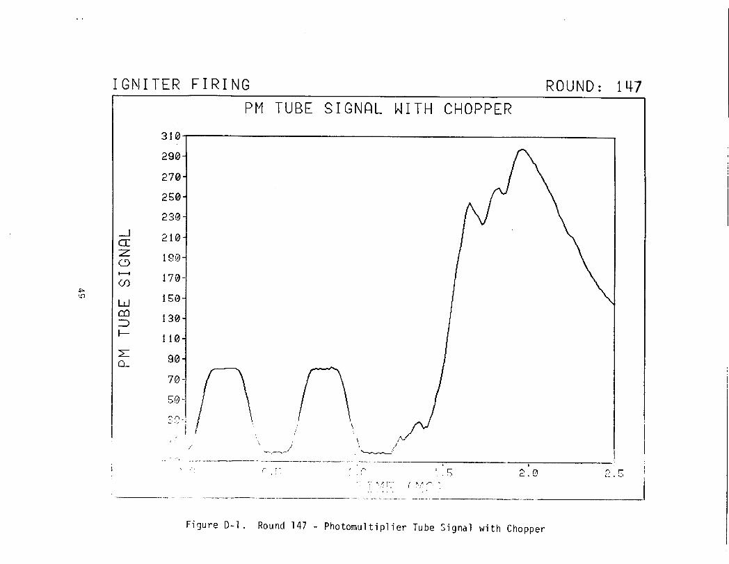
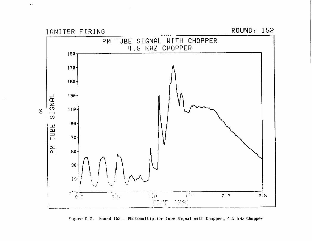
The outputs from the detector are shown in Appendix D. Figures 01-03 show the results of the first tests using the PRrn2 igniter containing mo and eimi te. The chopper was operated at 1. 7 kHz in Figure 01. In the next two tests, Figures 02 and 03, the frequency of the chopper was increased to its highest operating frequency of approximately 4.3 kHz. Important regions of the flame emission are masked by the rather low chopper frequency and the results can only be used as providing a rough indication of the flame emission.
2. Two Volume ~lethod. The two volume method requires two detectors. The set up is shown in Figure 5 with the exception of the chopper which is not required for this method. One detector (XP1002, set at 900 V) monitored both the relative lamp intensity (I 1) prior to ignition and the relative lamp intensity plus flame emission (!3) during the event. The second detector (CVP 150, set at 1350 V) monitored the flame emission CI2). For this method a correction was made to account for the different sensitivities of the two photomultipliers. This was done by placing the reference lamp in the position of the event and illuminating equally the ends of the two fiber optics. The output voltages were monitored
13c. Klingenberg~ K. J, White~ J. D. Knapton~ and W. F. Morrison~ '~eview of Spectroscopic Temperature Measurement Methods for Ballistic Applications, " USARRADC0/1 Teahniaa l Report being reviewed ( 19:J 2).
22
on an oscilloscope and were divided to obtain a correction factor which was applied arbitrarily to the output of the CVP 150 photomultiplier. The response from the XP1002 and the adjusted CVP 150 output was digiti:ed using the BRL ballistic data acquisition system (l:lALDAS). 'l'l1e results ar•: given in Appendix E.
It was found that the position of the fiber optics in the mounting plate (Figure 5) was very important for obtaining satisfactory results. A flush mount with the mounting plate was used for the tests. Also, it was found that a 0.3 neutral density filter was necessary when the booster charge consisted of Unique propellant. The neutral density filter was located on the flame side of the ~a line filter.
E. Temperature Data
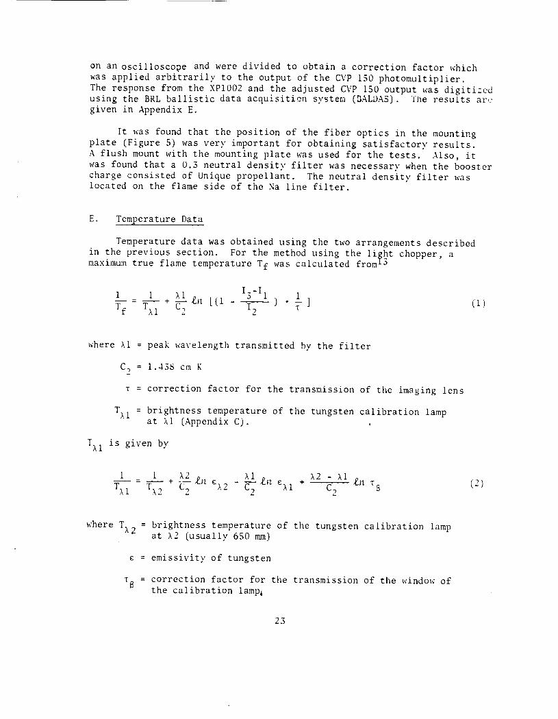
Temperature data was obtained using the two arrangements described in the previous section. For the method using the liybt chopper, a maximum true flame temperature Tf was calculated from ~
where \1 = peak wavelength transmitted by the filter
c2
= 1.438 em K
T = correction factor for the transmission of the imaging lens
= brightness temperature of the tungsten calibration lamp at \1 (Appendix C).
TAl is given by
1
TAl
= brightness temperature of the tungsten calibration lamp at \2 (usually 650 mm)
E = emissivity of tungsten
TB = correction factor for the transmission of the window of the calibration lamp,
23
( 1)
(2)
Based on earlier studies with a similar set-up by one of the authors (G. Klingenberg), values for 1 and 1
6 were set equal to 0.41 and 0,98.
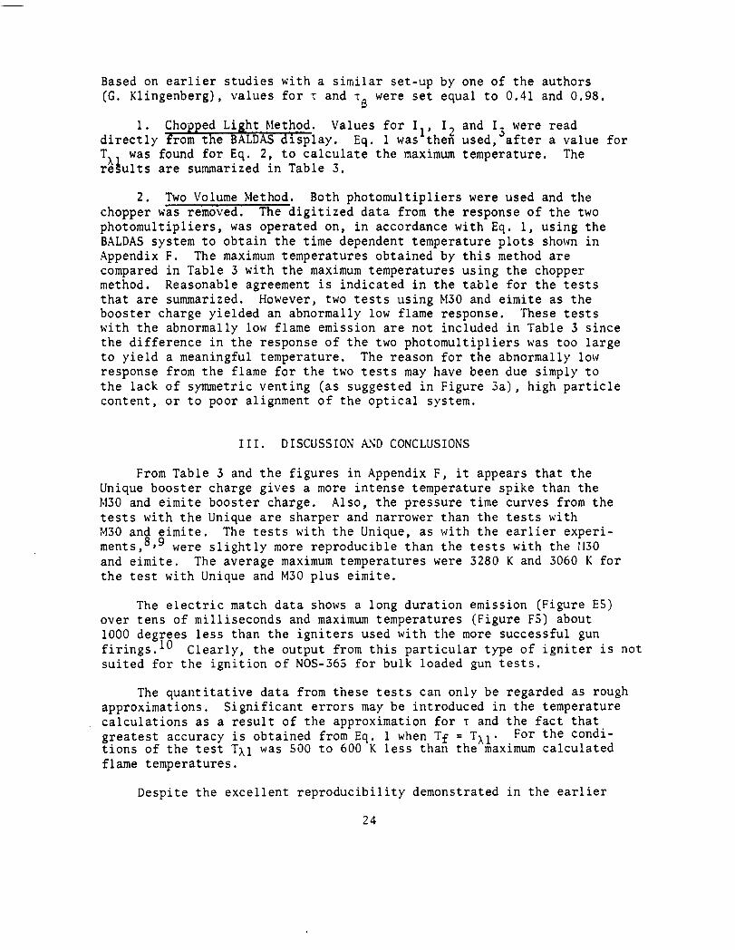
1. Chopped Light Method. Values for I 1, I, directly from the BALDAS display, Eq. 1 was theft TA was found for Eq. 2, to calculate the maximum re§ults are summarized in Table 3.
and I- were read .)
used, after a value for temperature. The
2. Two Volume Method. Both photomultipliers were used and the chopper was removed. The digitized data from the response of the two photomultipliers, was operated on, in accordance with Eq. 1, using the BALDAS system to obtain the time dependent temperature plots sho\m in Appendix F. The maximum temperatures obtained by this method are compared in Table 3 with the maximum temperatures using the chopper method. Reasonable agreement is indicated in the table for the tests that are summarized. However, two tests using ~130 and eimite as the booster charge yielded an abnormally low flame response. These tests with the abnormally low flame emission are not included in Table 3 since the difference in the response of the two photomultipliers was too large to yield a meaningful temperature. The reason for the abnormally low response from the flame for the two tests may have been due simply to the lack of symmetric venting (as suggested in Figure 3a), high particle content, or to poor alignment of the optical system.
III. DISCUSSION ~~D CONCLUSIONS
From Table 3 and the figures in Appendix F, it appears that the Unique booster charge gives a more intense temperature spike than the M30 and eimite booster charge. Also, the pressure time curves from the tests with the Unique are sharper and narrower than the tests with M30 and eimite. The tests with the Unique, as with the earlier experiments,8,9 were slightly more reproducible than the tests with the 1130 and eimite. The average maximum temperatures were 3280 K and 3060 K for the test with Unique and M30 plus eimite,
The electric match data shows a long duration emission (Figure ES) over tens of milliseconds and maximum temperatures (Figure FS) about 1000 degrees less than the igniters used with the more successful gun firings.lO Clearly, the output from this particular type of igniter is not suited for the ignition of NOS-365 for bulk loaded gun tests.
The quantitative data from these tests can only be regarded as rough approximations. Significant errors may be introduced in the temperature calculations as a result of the approximation for 1 and the fact that greatest accuracy is obtained from Eq. 1 when Tf = TAl. For the conditions of the test TAl was 500 to 600 K less than the maximum calculated flame temperatures.
Despite the excellent reproducibility demonstrated in the earlier
24
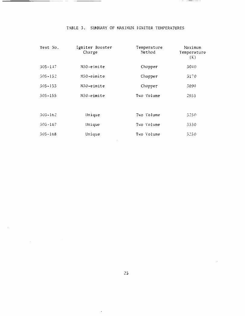
TABLE 3. SUMMARY OF ~IAXHIUM IGNITER THIPERATURES
Test :-.lo. Igniter Booster Temperature ~laximum
Charge ~let hod Temperature (K)
305-l-17 ~130-eimite Chopper 30-10
305-152 ~130-eimi te Chopper 3170
305-153 ~130-eimite Chopper 3090
305-155 ~130-eimi te Two Volume 2955
305-162 Unique TI\O \' o l ume 3250
305-167 Unique Two \'olume 3330
305-168 Unique TI\O \'olume 3250
25

high speed photographic tests with the igniter containing the Unique booster charge, the data obtained from the present investigation clearly shows large variations in the time dependent luminosity and pressure. Whether further improvements in igniter reproducibility are possible and whether such improvements would lead to improved ballistic reproducibility is only speculative. However, based on the correlation between improvements in breech pressure reproducibility with the improvements in igniter reproducibility demonstrated in Ref, 3, we conclude that further improvements in ballistic control are possible.
A greater effort should be placed on the energy required for propellant ignition, if further studies on igniter systems are pursued. For example, th~ igniters used in the present study contained on the order of 103 J whereas it has been demonstrated that less than 1 J is sufficient for igniting the propellant.l4 If the input energy can be reduced and at the same time generate an acceptable gas generation rate, then problems due to pressure waves and possible secondary ignition sites should be greatly reduced.
14J. D. Knapton~ I. C. Stobie and K. E. Travis~ "Liquid Pr>opeUant Characterization Tests at Maximum Loading Densities~" 19?9 JAllNAF Pr>opuZsion Meeting~ CPIA PubUaation No. :300~ VoZ. I, AppUed Physias Laboratory~ SiZver Spring~ MD~ p. :39:3 (19?9).
26
REFERENCES
1. J. D. Knapton, I. C. Stobie and R. H. Comer, 11 Pyrotechnic Primer Design for Liquid Propellant Guns," 13th JANNAF Combustion i'leeting, CPIA Publication No. 281, Vol. I, Applied Physics Laboratory, Silver Spring, NO, p. 187 (1976).
2. J. D. Knapton and I. C. Stobie, "Conditions Required for Controlling Breech Pressure During a Bulk Loaded Liquid Propellant Gun Firing (U)," 16th JANNAF Combustion i·leeting, CPIA Publication ;\o. 308, Vol. IV, Applied Physics Laboratory, Silver Spring, t-ID, p. 51 .(1979).
3. J. D. Knapton and I. C. Stobie, "Bulk Loaded Liquid Propellant Guns: What Can Be Expected in Terms of Pressure Reproducibility?", Journal of Ballistics, Vol. III, p. 615 (1980).
4. A. R. Guzdar, S. S. Rhee and A. J. Erickson, "~lodeling Studies of the Liquid Propellant Gun," Foster-~liller Associates, Inc., Ballistic Research Laboratory Contract Report No. 57 (1971).
5. N. A. Messina, L. S. Ingram, Preston E. Camp, M. Ben Reuben and ~1. Sununerfield, "Compression-Ignition Sensitivity Studies of Liquid Propellants for Guns," Princeton Combustion Research Laboratories, Inc., Report No. PCRL-FR-79-004 (1979).
6. V. ~1. Boyle and E. A. O'Leary, "Ignition of NOS-365 Liquid Propellant Containing an Air Bubble Under Simulated Breech Pressurization Conditions," USARRADCOM Technical Report ARBRL-TR-02236 (1980).
7. J. ~landzy, K. Schaefer, J. Knapton and W. ~:orrison, :;Progress Report on Compression Ignition Sensitivity of NOS-365 Under Rapid Propellant Fill Conditions," 17th JANNAF Combustion Meeting, CPIA Publication No. 329, Vol. II, Applied Physics Laboratory, Silver Spring, ;.Jd., p. 309' (1980).
8. J.D. Knapton, I.C. Stobie and R. H. Comer, "Pyrotechnic Ignition Systems Used in a Medium Caliber Bulk Loaded Liquid Propellant Gun, 11
1978 JANNAF Propulsion Meeting, CPIA Publication No. 293, Vol. I, Applied Physics Laboratory, Silver Spring, p. 579 (1978).
9. J. D. Knapton, I. C. Stobie, R. H. Comer, B. Bensinger and D. Henry, "Results from a Study on the Ignition of Liquid Propellant Rounds in a ~ledium Caliber Gun Using a Radial Venting Primer, 11 USARRADCOM Technical Report (being reviewed), 1982.
10. J. D. Knapton, I. C. Stobie, R. H. Comer, D. Henry, B. Bensinger and L. Stansbury, "Charge Design Studies for a Bulk Loaded Liquid Propellant Gun," USARRADC0~1 Technical Report ARBRL-TR-02127 (1978). (AD C017813L)
11. W. F. McBratney, BRL, private communication.
27

12. K. E. Travis, "Closed Chamber Burning Characteristics of Selected Liquid Monopropellant s," 14th JANNAF Combustion ~1eeting, CPIA Publication No. 292, Vol. III, Applied Physics Laboratory, Silver Spring, MD, p. 1 (1977).
13. G. Klingenberg, K. J. \fuite, J. D. Knapton, and W. F. ~lorrison, "Review of Spectroscopic Temperature ~leasurement ~lethods for Ballistic Applications," USARRADCOM Technical Report being reviewed (19:32).
14. J.D. Knapton I. C. Stobie and K. E. Travis, "Liquid Propellant Characterization Tests at ~laximum Loading Densities," 1979 JANNAF Propulsion ~leeting, CPIA Publication No. 300, Vol. I, Applied Physics Laboratory, Silver Spring, MD, p. 393 (1979).
28

APPE:-:DIX A
IG~ITER ELE~IENTS A~D BOOSTER CHARGES USED I~ THE PYROTECH~IC IG~ITERS
29
TABLE A-1. PROPERTIES OF m 03/~1203 ELECTRIC ~lATCH
A-1 Electric ~latch. The electric matches selected for the study were manufactured by Atlas Chemical Industries, Inc.A-1 and were designated Nl03/N203. Physical dimensions of the match head, electrical resistance and chemical composition were taken from Ref. A-1 and are summarized in Table A-1. Total combustible mass is approximately 25 mg based on weighings before and after firings.A-2
Head Dimensions Resistance ''All Fire" Head Composition Width Length Thick- Conditions 1st 2nd 3rd
ness Coat Coat Coat mm mm mm ohm
-l. 0± -L8± 2.8± 1.2 to 1.4 O.SOA for (a) (a) (b) 0.8 1.5 0.8 SO ms
(a) 76.5% Lead Nononitrorescorcinate 8.5% Potassium Chlorate
15. 096 1/2 Sec. Nitrocotton, in Iso-Amyl Acetate
(b) 51 . 09o Cerium ~lagnesium 40.5% Lead Peroxide
6.5% Aluminum (Alcoa 11606 Standard unpolished) 2.0% Darco X
(c) 6 oz 376 Sec. Nitrocotton 1 gal Ethyl Ether (2 parts by vol.)
Ethyl Alcohol (1 part by vol.)
-lth Coat
(c)
A-lData Sheet 420, 5-?0, Atlas Chemical Industries, Inc., Aerospace Components Division, Valley Forge, PA 19481.
A- 2R. E. Bo~man, Applied Physics Branch, BRL, 1980.
31
5th Coat
(c)
TABLE A-2. T9E6 ELECTRIC IG~ITION ELE~IENT
Table A-2. Composition of the T9E6 Electric Ignition Element
Barium Nitrate, class 1
Lead Dioxide, grade A
PETN
Zirconium (granular)
Zirconium, 120 grade
Weight: 4.40 - .80 grains = .286 - .052 gms
Volume of ignition element cavity
(~leasured after firing)
Volume of booster cavity
Firing Voltage used in tests: 366 volts
Label: T9E6 Ignition Element DA-28-017-501-0RD-3865 Olin-~lat hie son Chemical Corp. Lot WCC 1-3, Date: 8-60
32
20%
20%
32.5%
7.5%
3 .22 em
3 2.1 em
Ref
A-3
A-3 A-5
A-4
-- -------------------
TABLE A-3. PROPERTIES OF THE BOOSTER CHARGES USED IN THE RADIALLY VENTING PYROTECHNIC PRUIERS
Flame Force 6 Propellant Temp, K J/kgxlO Form Used in Igniter
Hercules Unique 3650 1.14 disc, 1.5 mm diameter
Eimite 2590 0.53 strand, 2 nun dia; 15 mm long
M30 3040 1.09 disc, 11 nun OD, 6.4 mm ID; 3.5 mm thick
COt--IPOSITION
Hercules Unique- 30% NG; 68% NC; 1.15% EC, Stabilizer; .75% K2so4
Eimite- 40% NC: 27.6% KN03; 16.7% Mg; 9,89o S; 5.9% Resorcinol
M30 - 27.97% NC; 22.48% NG; 0.1% Graphite; 1.5 Et Centralite; 1.0% K2so4 47.65% i'IGU
A-JFrivate communication from Bert Grollman, Ballistic Research Laboratory, June 76.
A-4L. Stansbury and A. J, Budka, "A Mathematical Uodel for DesignEvaluation of Vented Ammunition Boxes, 11 BRL l1R 2590, Feb ?6. (AD B00978SL)
A-SFrivate communication from E. Freedman, Ballistic Research Laboratory, Dec. 1981.
33

APPENDIX B
PRESSURE TIME DATA
35
I
I
R[[l l!ll 11)-HQ l!l
~· ' (HfiHH[l I IIIIX-P.D. !Pill
5
s
; : Jl I
211 z
II
Figure Bl. T9E6 Igniter and a Booster Charge of M30 and Eimite
!I
I
ll[[l 1!13 IP-111 .. Sll tiiiiML I RRX-P.D. !1252
I
~· s
1: 31~
211 z
II
Figure B2. T9E6 Igniter and a Booster Charge of M30 and Eimite
37
I
I II[U 113 ...... '41 II em I ..........
I ... I
I : ., .I
r II
Figure B3. T9E6 Igniter and a Booster Charge of M30 and Eimite
.. II
II
1111. Ill
I 'I I ... 11 ~ I .-f'.l. IIJJI
II
II
1.: .. I
Figure B4. T9E6 Ig~iter and a Booster Charge of Unique
38
I.
•
•;
... I
•• II
II
IIEtLJII I 'I ID·IIJ. II I. OIINNI:L.. I
IIIIX-f'.D. 11'1'11
IJ
• II
~ . &II
~ ~ .w ~
Figure B5. T9E6 Igniter and a Booster Charge of Unique
~· II
I&
11m. Ill
I 'I ID-111 E!l •• CliiiJII[l 'I IIIIX-f'.D. IK!il
ll
• II
~ . &I~ lr~ nl I r: ~
'tl II.
Figure B6. T9E6 Igniter and a Booster Charge of Unique
39
"" II
II
litE\. Ill 10-111 • ,.
I 'I CtiNINa. I ....... a. IIBI
II • II
I : .,
!!(
·' I'll
I
Figure B7. T9E6 Igniter and a Booster Charge of Unique
• II
II IDL Ill lt-.. IL I.
I 'I CJIIII[L _)_ ....... a. 101
II • II
' I
Iii I;
J F.
Figure B8. T9E6 Igniter and a Booster Charge of Unique
40
ll! .~
IR
II
I&
fi[[L. 211 It-NO lil! 1111 l'f OfiiOin I 110(-f' .0. 11182
12 Ill
II
~ Iii :t D L
~ lLI
~ 'II '
" 21
Figure 69. T9E6 Igniter and a Booster Charge of Unique
J
Figure 810.
RE£l2ll It-Ill l'f Clllllll£l I 11111-f'.D. l'flll
,,
ll
Electric Match Igniter and a nooster Charge of Unique
41

IIIII. ZJI It-til X lO OIIIG. I .... a. 11n
I.
I ll
•
Figure 811. Electric i~atch Igniter and a Booster Charge of Unique
42
APPENDIX C
CHARACTERISTICS OF THE TUNGSTEN RIBBON FILAMENT WIP
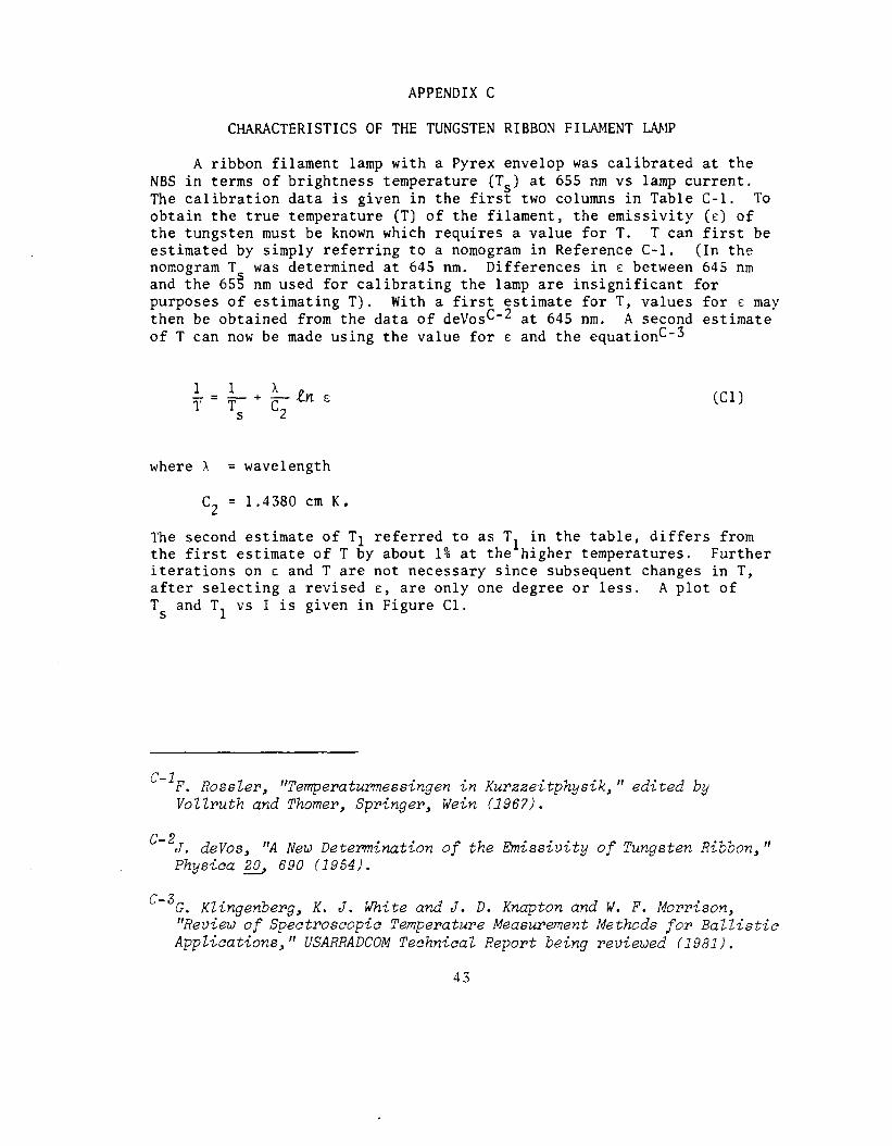
A ribbon filament lamp with a Pyrex envelop was calibrated at the NBS in terms of brightness temperature (Ts) at 655 nm vs lamp current. The calibration data is given in the first two columns in Table C-1. To obtain the true temperature (T) of the filament, the emissivity (E) of the tungsten must be known which requires a value for T. T can first be estimated by simply referring to a nomogram in Reference C-1. (In the nomogram T was determined at 645 nm. Differences in E between 645 nm and the 65S nm used for calibrating the lamp are insignificant for purposes of estimating T). With a first estimate forT, values forE may then be obtained from the data of deVosC-2 at 645 nm. A second estimate of T can now be made using the value for E and the equationC-3
(Cl)
where \ = wavelength
c2 = 1.4380 em K.
The second estimate of T1 referred to as T1 in the table, differs from the first estimate of T by about 1% at the higher temperatures. Further iterations on E and Tare not necessary since subsequent changes in T, after selecting a revised E, are only one degree or less. A plot of Ts and T1 vs I is given in Figure Cl.
C-lF. Rossler, "Temperaturmessingen in Kurzzeitphysik," edited by Vollruth and Thorner, Springer, Wein (1967).
C- 2 d "A .. f hEm". "t fT R"bb II J. eVos, New Determ&nat&on o t e &ss&V& y o ungsten & on, Physica ~ 690 (1954).
C- 3G. Klingenberg, K. J. White and J. D. Knapton and W. F. Morrison, '~eview of Spectroscopic Temperature Measurement Methods for Ballistic Applications," USARRADCOM Technical Report being reviewed (1981).
43
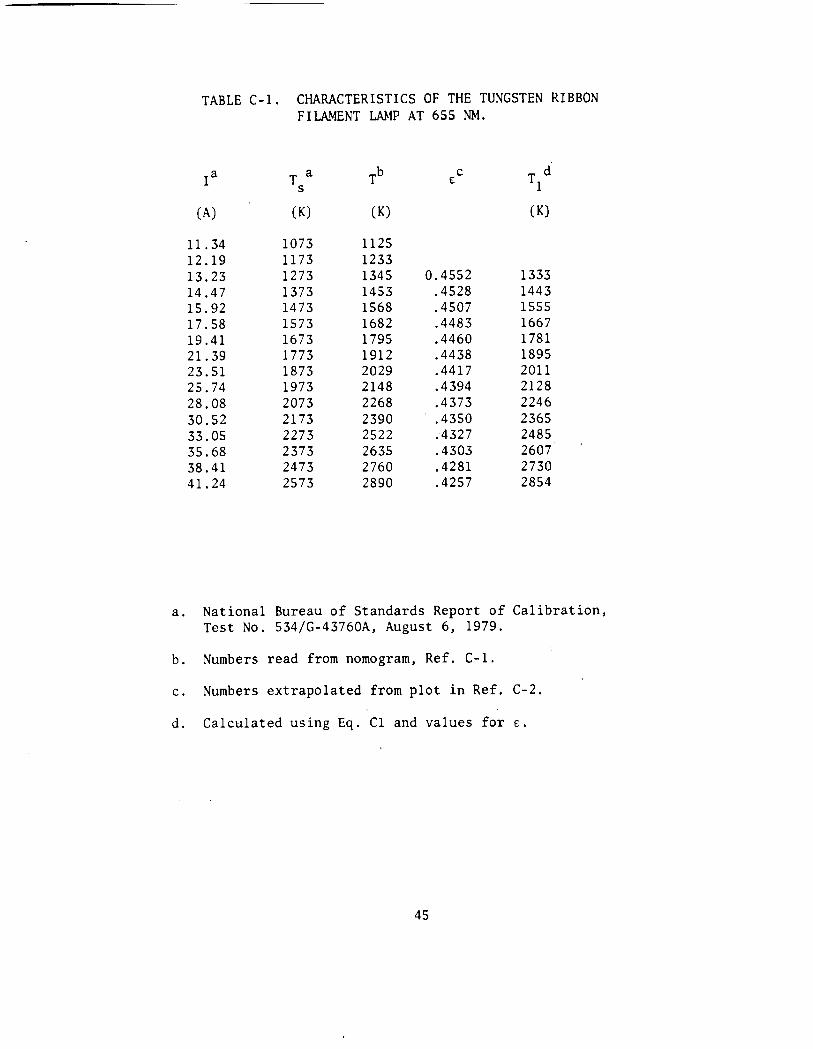
TABLE C-1. CHARACTERISTICS OF THE TUNGSTEN RIBBON FILAl\fENT W1P AT 655 NM.
I a T a Tb c T d £ s 1
(A) (K) (K) (K)
11.34 1073 1125 12.19 1173 1233 13.23 1273 1345 0.4552 1333 14.47 1373 1453 .4528 1443 15.92 1473 1568 .4507 1555 17.58 1573 1682 .4483 1667 19.41 1673 1795 .4460 1781 21.39 1773 1912 .4438 1895 23.51 1873 2029 .4417 2011 25.74 1973 2148 .4394 2128 28.08 2073 2268 .4373 2246 30.52 2173 2390 .4350 2365 33.05 2273 2522 .4327 2485 35.68 2373 2635 .4303 2607 38.41 2473 2760 .4281 2730 41.24 2573 2890 .4257 2854
a. National Bureau of Standards Report of Calibration, Test No. 534/G-43760A, August 6, 1979.
b. Numbers read from nomogram, Ref. C-1.
c. Numbers extrapolated from plot in Ref. C-2.
d. Calculated using Eq. Cl and values for £.
45

3000
. .,:
2000-
""'----_..----~---__..L-____ _,j 20 30
CURRENT 40 50
(A)
Figure Cl. Plot of T5
and r1 vs Lamp Current
46

APPENDIX D
HIISSION TIME DATA. CHOPPED LIGHT ~IETHOD
47
IGNITER FIRING ROUND: 14-7 Pt1 TUBE SIGNAL WITH CHOPPER
310
290
270
250
230 _j 210 cr z 190 C) ..._...
170 (/) .$:>-\[) 150 w
co 130 ::::::> I- 110 L: 90 Q_
70-
S!u-
~>~t -j
I /
·\ /'J . / .~'
' I -, ,-, ·' ,f'"\. :'. ~ 2.0 2.5 .. -· , /' r--
_:, 1-
--- -~-------~---- ~----·---------
Figure D-1. Round 147 - Photomultiplier Tube Signal with Chopper
V1 0
IGNITER FIRING ROUND: 152
_J
a: z C) t--1
(/)
w 0)
:::> I-
:L: 0...
190
170
150
130
110
90
70
50
PM TUBE SIGNAL WITH CHOPPER 4-.5 KHZ CHOPPER
-' .-.,_1:·---------------------,.-------.· I
l.~ '.n ! -~ 2.~ 2.5 -;- -· 1·.~ I : } ~ : .
----------··--· ----------
Figure D-2. Round 152 - Photomultiplier Tube Signal with Chopper. 4.5 kHz Chopper
(.n
f-'
IGNITER FIRING ROUND: 153
__J
a: z C) 1-1
(/)
w CCl ::)
1-
::z C.L
PM TUBE SIGNAL WITH CHOPPER L~. 5KHZ CHOPPER
~10~--------------------------------------------------~
390 370 350
310
290 270 250 230-210 190 170 150 1 ?0·
110 !;J0-
70 50
~;,.J-~ n. (\ I I • !,
- ~ .t·). '------~ ---· •.
r ·-· -- - -··-.-·-- "-----------r, --------,:------
. r ;-'.(I ,..., c c. I 0
-· ____ ,. _________ -----
Figure D-3. Round 153 - Photomultiplier Tube Signal with Chopper, 4.5 kHz Chopper

APPE~DIX E
HIISSION TIME DATA. T\\0 VOLU~IE ~IETHOD
53
Ul Ul
IGNITER FIRING ROUND: 155
0 lf) ~
CL > u
PISTON RADIAL PRIMER M30 EIMITE PM TUBE OUTPUTS
80 80~-------------------------------------------
70
60 60
50 (\j
<S> XPlOU2 0 4-0 4-0 ..-i
CL X
30
20 20
10-
I rJ\. ·-......._:.·
! --- ---.----· . -------i
! . s r·.., r· ·-··. '··'
J . ('I
-: · r. :, ~ r .· r t,, ,..... ,~ , • , , ! • i ~ • . I
---------- . -~· ~--·----·---·--···- ----·---- - ~------------ -------------------------·---·-----
figure E-1. Round 155- M30 an~ ~imite, Photomultiplier Tube Outputs
IGNITER FIRING ROUND: 162 IGNITER UNIQUE 100
380 360
360 340
340 320 .X.PlJU2 I
320 300 I\ 1\ I \ I \
300 280 I \1 \ .. \ 280 260 I \
260 240 \ I 240 22@ I \ I" (S)
(\J 220 lJ) 200
l I \ <S)
\ til <S> ..........
I I ' r \ "7' 200 180 \ .......... I \ I ' I " \ I ' CL CL 180 > 160 \ \ I I \ X ..... 160 u
140 t I ' I \
I I 1'\.f \ ,, 140 120 I \ 120 100 I \
\ I \ 100 80 \I\ J \
80 60 \. \
60 L~0 "' '-;:!)-I \ r•-0-
\,. "'- '--
20- 01- ~ ""' .·.· I I
.---'!-
D. D!) 0 .. ~:~ 0. ~~0 0. '75 ··- T ME ! .. =- ( r1S)
Figure E-2. Rou1d 162- Igniter Unique 100, Photomultiplier Tube Outputs
U1 '-I
IGNITER FIRING
150 150
125 125
0 100 N 100 L..J1 <S> ........... <S> o.._ ...........
> o.._ u 75 X 75
50 50
25
IGNITER UNIQUE 100 PM TUBE OUTPUTS
Xl'l002
------- ·-· ···--------------- ---- -
ROUND: 167
. ·.
J .. s
Figure E-3. Round 167- Igniter Unique 100, Photomultiplier Tube Outputs

trl (';:>
IGNITER FIRING ROUND: 168
0 lD ...-i
Q_
> u
IGNITER UNIQUE 100 PM TUBE OUTPUTS
100 100.-------------------------------------------~
80 80
;:PI 002
60 60 (\J
0 0 ......... Q_
40 X
40
20 20
I i1 I ~-:·.r.--,, .':·.·
··r, . ""'v·
--- -- r·;_ __ _ .. r !. • ~.
T T ~· .. ~ i
Figure E-4. Round 168 - Igniter Unique 100, Photomultiplier Tube Outputs
CLOSED CH~MBER
ELECTRIC M~TCH (W BULB PLUS FL~ME)
1050 1050
(/) (/)
I- I-
z ::=>
>~ a: ~ I-
>I-
>-950 ~
a: ~ I-
co ~ a:
>-650 I-
(/) (/)
0 0 z z
XP1002
950
650
ROUND: 118 PLOT: 3 (M103) ~ND (FL~ME)
4-50 4-50 -l----,-----,--------,----,.----"""T----1._--j () 20 40 60 80 100 120
TIME (MS)
Figure E-5. Round 118- Electric Match (Ml03), Photomultiplier Tube Outputs

APPENDIX F
Ta!PERATURE TUIE DATA. TIVO VOLU~IE ~IETHOD
61
C]\
VI
IGNITER FIRING ROUND: 155
..-... ~ ..........
w a::: ~ I-a a::: w Q_
::E w I-
R~DI~L PISTON PRIMER M30 EIMITE TEMPERATURE
3000~----------------------------------------------~
2900
2800
2700
2600
2500
2~00
2300
2200
I '
2100-~--------------~----------------------l 0.5 1 . 0
TIME (MS)
Figure F-1. Round 155 - M30 plus Eimite, Temperature vs Time
1 . 5
IGNITER FIRING ROUND: 162
IGNITER UNIQUE 100
3400
3300 A
3200 I.Jt .--.. 3100
I
~ I .........
3000 I
w 2900
I (X:: I \ ::::> I I I- 2800
I cr I 0\ (X:: 2700 I \ ~ w I J\
I o_ 2600 I I I \ :L
"I \J \ w 2500 I I- \ '\
I ._
/ \
w 2400- ,_,._J ' ""' :L 2300 ""'
CI ....._.,.... ___
_j 2200
-,.. - ~ ---~ .... --LL
2100
2.?1!'?10-
1 ~J00 -. 0. !'!>0 0.25 0.50 0.75
TIME ( ~~~·] S)
Figure F-2. Round 162 - Igniter Unique 100, Temperture vs Time
IGNITER FIRING ROUND: 167
w 0:::: => 1-a: 0:::: w Q._
:E w 1-
IGNITER UNIQUE 100 TEMPER~TURE
3~00~----------------------------------------------------~
3300
3200
3100
3000
2900
2800
2700
2600
2500
I '
C':. ,_,_r::; :"1 . :·; ·!. t .: • 0. 75 0. 8S 0. OS . !'S ! ~ r- I ·>c ,_ • ,_ .... 1
( 1,!1 (' ~ .. I I...___, ...
'-----~ --~ ·-~ .. ~~-----··· . ·-- - ~-- . --~ .. ·-----'
Figure F-3. Round 167 - Igniter Uniquo 100, Temperature vs Time
c,, 0\
IGNITER FIRING ROUND: 168
,.-...
Y::: .__,.
w er: =:)
1-CI er: w CL :L w 1-
IGNITER UNIQUE 100 TEMPER~TURE
3100~----------------------------------------------------~
3000
2900
2800
2700
2600
2500
2400
I
2300 !/
2200-rl ----.-----~--~----~----~--~~--~----~--------~ 0. 39 0. LU3 0. 58 0. 68 0. 78 0. 88 0. 98 1 . 08 1 . 18 1 . 28 1 . 38
TIME (MS)
Figure F-4. Round 168 - Igniter Unique 100. Temperature vs Time

CLOSED CH~MBER ROUND: 118
'""" Y:: ......._.
G w 0
G~S TEMPER~TURE OF ELECTRIC M~TCH
220@~----------------------------------------------------~
2150-
2100-
2050
2000-
1950-
1900-
1850-
I 1800-,
1750-j) 'I
·' f 7(11') -: ·-----,-----.-------r------.-----.------.-----,
1·1 ! 0 20 30 L! 0 50 GO 70
T T t·-1 i-. --' '-- --------·-------------------l
Figure F-5. Round 118- Electric Match (Ml03), Temperature vs Time
APPENDICES REFERENCES
A-1. Data Sheet 420, 5-70, Atlas Chemical Industries, Inc., Aerospace Components Division, Valley Forge, PA 19481.
A-2. R. E. Bowman, Applied Physics Branch, BRL, 1980.
A-3. Private communication from Bert Grollman, Ballistic Research Laboratory, June 76.
A-4. L. Stansbury and A. J. Budka, "A ~lathematical ~!odel for Design-Evaluation of Vented Ammunition Boxes," BRL ~~ 2590, Feb 76. (AD B009785L)
A-5. Private communication from E. Freedman, Ballistic Research Laboratory, Dec. 1981.
C-1. F. Rossler, "Tem-peraturmessingen in Kurzzei tphysik," edited by Vollruth and Thorner, Springer, Wein (1967),
C-2. J. deVos, "A New Determination of the Emissivity of Tungsten Ribbon," Physica IQ, 690 (1954).
C-3. G. Klingenberg, K. J. White and J. D. Knapton and W. F. ~lorrison,
"Review of Spectroscopic Temperature Heasurement ~lethods for Ballistic Applications," USARRADCOM Technical Report being reviewed (1981).
68
DISTRIBUTION LIST
No. of Copies
12 Conunander
Organization
Defense Technical Info Center ATTN: DDC-DDA Cameron Station Alexandria, VA 22314
1 Director Defense Advanced Research
Projects Agency ATTN: H. Fair 1400 Wilson Boulevard Arlington, VA 22209
1 HQDA (DAr-IA, C. Church) Washington, DC 20310
1 Commander US Army Materiel Development
and Readiness Command ATTN: DRCmiD-ST 5001 Eisenhower Avenue Alexandria, VA 22333
3 Commander US Army Armament Research
and Development Command ATTN: DRDAR-TSS (2)
DRDAR-SCA, M. Devine Dover, NJ 07801
4 Commander US Army Armament Research
and Development Command ATTN: DRDAR-LCA, D. Downs
A. Beardell DRDAR-LCE, N. Slagg DRDAR-LCS, W. Quine
Dover, NJ 07801
No. of Copies Organization
2 Corrunander US Army Armament Research
and Development Corrunand Benet Weapons Laboratory ATTN: DRDAR-LCB-TL
P. Votis Watervliet, !\'Y 12189
1 Corrunander US Army Armament ~lateriel
Readiness Command ATTN: DRSAR-LEP-L, Tech Lib Rock Island, IL 61299
1 Commander US Army Aviation Research
and Development Command ATTN: DRDAV-E 4300 Goodfellow Blvd. St. Louis, MO 63120
1 Director US Army Air Mobility Research
and Development Laboratory Ames Research Center l-loffett Field, CA 94035
1 Commander US Army Communications Research
and Development Command ATTN: DRDCO-PPA-SA Fort ~,Jonmouth, ::lJ 07703
1 Commander US Army Electronics Research
and Development Command Technical Support Activity ATTN: DELSD-L Fort l-lonmouth, NJ 07703
l Commander US Army Harry Diamond Labs ATTN: DELHD-TA-L 2800 Powder Mill Road Adelphi, ~ID 20783
DISTRIBUTION LIST
No. of Copies
1 Commander
Organization
US Army Missile Command ATTN: DRSMI-R Redstone Arsenal, AL 35809
1 Commander US Army t-lissle Command ATTN: DRSMI-YDL Redstone Arsenal, Al 35809
2 Commander US Army Mobility Equipment
Research and Development Cmd ATTN: DRDME-WC
DRSME-RZT Fort Belvoir, VA 22060
1 Commander US Army Tank Automotive
Research and Development Cmd ATTN: DRDTA-UL Warren, NI 48090
No. of Copies
1 Commander
Organi::.ation
Naval Surface Weapons Center ATTN: W. C. \He land Dahlgren, VA 22448
2 Commander ;-.;aval Surface Weapons Center ATT~: 0. Dengel
K. Thorsted Silver Spring, ~.to 20910
2 Commander ;-.;aval Weapons Center ATTN: C. Mallory
S. Wood China Lake, CA 93555
2 Commander Naval Ordnance Laboratory ATTN: K. ~tueller
G. Poudrier Indian Head, :10 20640
1 Army Research Office Durham 1 Superintendent ATTN: R. Singleton P. 0. Box 12 211 Research Triangle Park, NC 27709
2 1 Director
US Army TRADOC Systems Analysis Activity
ATTN: ATAA-SL, Tech Lib l White Sands Missile Range NH 88002
1 Office of the Chief of 2 Naval Operations
ATTN: Code NOP-351G Washington, DC 20360
Naval Postgraduate School ~~nterey, CA 93940
AFATL/ATI~G, 0. Heiney OLD, D. Davis
Eglin, AFB, FL 32542
AFOSR/NA (L. Caveny) Bldg. 410 Bolling AFB, DC 20332
US Bureau of ~·lines ATTN: R.A. Watson 4800 Forbes Street Pittsburgh, PA 15213
1 Commander 1 Director Naval Sea Systems Command ATTN: J.W. Murrin (SEA-62R2) National Center Building 2, Room 6E08 Washington, DC 20362
70
Los Alamos Scientific Laboratory ATTN: T. D. Butler P.O. Box 1663 Los Alamos, ~M 87545
DISTRIBUTION LIST
No. of Copies Organization
l Director Jet Propulsion Laboratory ATTN: Tech Lib 4800 Oak Grove Drive Pasadena, CA 91103
2 Director National Aeronautics and
Space Administration ATTN: MS-603, Tech Lib
t-IS-86, Dr. Povinelli 21000 Brookpark Road Lewis Research Center Cleveland, OH 44135
l Director National Aeronautics and
Space Administration Manned Spacecraft Center Houston, TX 77058
l The BDM Corporation ATTN: Dr. T.P. Goddard P.O. Box 2019 2600 Cearden Road Monterey, CA 93940
l Calspan Corporation ATTN: E. Fisher P. 0. Box 400 Buffalo, NY 14221
l Food & Machinery Corporation Northern Ordnance Division ATTN: J. Oberg Columbia Heights Post Office Minneapolis, MN 55421
3 General Electric Ordnance Dpt ATTN: J. t-landzy
R. E. t-1ayer H. West
100 Plastics Avenue Pittsfield, ~lA 01201
71
No. of Copies Organization
2 General Electric Company Armanent Systems Department ATTN: E. Ashley
M. Bulman Burlington, VT 05401
l Pulsepower Systems, Inc. ATTN: L.C. Elmore 815 American Street San Carlos, CA 93555
l AFELt-1, The Rand Corporation ATTN: Library-D 1700 ;.lain Street Santa Monica, CA 90406
l Science Applications, Inc. ATTN: R. Edelman 23146 Cumorah Crest Woodland Hills, CA 91364
l Shock Hydrodynamics ATTN: W. Anderson 4710-16 Vineland Avenue N. Hollywood, CA 91602
l TRW Systems ATTN: Rl-1032, E. Fishman One Space Park Redondo Beach, CA 90278
l Director Applied Physics Laboratory The Johns Hopkins University Johns Hopkins Road Laurel, MD 20810
2 Director Chemical Propulsion Information
Agency The Johns Hopkins University ATTN: T. Christian
Tech Lib Johns Hopkins Road Laurel, MD 20810

DISTRIBUTIO~ LIST
No. of Copies Organization
Pennsylvania State University Uept. of Mechnical Engineering ATTN: K. Kuo
1
2
1
1
1
University Park, PA 16802
Princeton Combustion Research Laboratories, Inc.
ATTN: N. A. ~1essina ~1. Summerfield
1041 US Highway One North Princeton, NJ 08540
SRI International ATTN: Code L3106, G.A. Branch 333 Ravenswood Avenue Menlo Park, CA 94025
University of Mississippi r.lechanical Engineering Department University, MS 38677
University of Illinois Dept. of Chemistry ATTN: Douglas Taylor Urbana, IL 61801
Aberdeen Proving Ground Di r, USAI\ISAA
ATTN: DRXSY-D DRXSY-MP, H. Cohen
Cdr, USATEC0~1
ATT~: DRSTE-TO-F Dir, USACSL, Bldg. E3516, EA
ATTN: DRDAR-CLB-PA
n
USER EVALUATION OF REPORT
Please take a few minutes to answer the questions below; tear out this sheet, fold as indicated, staple or tape closed, and place in the mail. Your comments will provide us with information for improving future reports.
1. BRL Report Number __________________________________________ _
2. Does this report satisfy a need? (Comment on purpose, related project, or other area of interest for which report will be used.)
3. How, specifically, is the report being used? (Information source, design data or procedure, management procedure, source of ideas, etc.) ______________________________________________________ ___
4. Has the information in this report led to any quantitative savings as far as man-hours/contract dollars saved, operating costs avoided, efficiencies achieved, etc.? If so, please elaborate.
5. General Comments (Indicate what you think should be changed to make this report and future reports of this type more responsive to your needs, more usable, improve readability, etc.) -------------
6. If you would like to be contacted by the personnel who prepared this report to raise specific questions or discuss the topic, please fill in the following information.
Name: -----------------------------------------------Telephone Number: -----------------------------------------------
Organization Address: ______________________________________________ _
- - - - - -FOLD HERE -
Director US Army Ballistic Research Laboratory Aberdeen Proving Ground, MD 21005 Ill II I
OFFICIAL BUSINESS
PENAL.TY FOR PRIVATE USE. 1300 BUSINESS REPLY MAIL FIRST CLASS PERMIT NO 12062 WASHINGTON,DC
POSTAGE WILL BE PAID BY DEPARTMENT OF THE ARMY
Director US Army Ballistic Research Laboratory ATTN: DRDAR-TSB Aberdeen Proving Ground, MD 21005
NO POSTAGE NECESSARY IF MAILED
IN THE UNITED STATES
- - - - - - - - FOLD HERE - - - - - - - - -