Us Airfield Manual 2012
62
Transcript of Us Airfield Manual 2012

8/10/2019 Us Airfield Manual 2012
http://slidepdf.com/reader/full/us-airfield-manual-2012 1/62

8/10/2019 Us Airfield Manual 2012
http://slidepdf.com/reader/full/us-airfield-manual-2012 2/62
AIRFIELD PAVEMENT DESIGN WITH CONCRETE PAVERSU.S. Version - FOURTH EDITION - 2010
by
Roy D. McQueen, P.E.
Roy D. McQueen & Associates, Ltd.22863 Bryant Court – Suite 101Sterling, Virginia USA 20166
Tel: 703-709-2540Fax: 703-709-2535
E-mail: [email protected]
John Knapton, Ph. D., Chartered Engineer85 Monkseaton Drive
Tyne & WearWhitley Bay NE26 3DQ
United KingdomTel/Fax: +44-191-252-8333E-mail: [email protected]
John Emery, Chartered Engineer9 Rowallan Drive
PutnoeBedford MK41 8AW
United KingdomTel/fax: +44-1234-350-310
E-mail: [email protected]
David R. SmithTechnical Director
Interlocking Concrete Pavement Institute13921 Park Center Road - Suite 270
Herndon, VA 20171Tel: 703-657-6900Fax: 703-657-6901
E-mail: [email protected]
© Copyright 2003 - Interlocking Concrete Pavement Institute – Updated May 2012

8/10/2019 Us Airfield Manual 2012
http://slidepdf.com/reader/full/us-airfield-manual-2012 3/62
ContentsCHAPTER I: INTRODUCTION................................................................................................. 1
1.1 Basis for Design Method ............................................... .......................................... 1 1.2 FAA Policy ................................................. ....................................................... ...... 1 1.3 Organization ............................................... ....................................................... ...... 1
CHAPTER II: ELEMENTS OF INTERLOCKING CONCRETE PAVEMENT .................. 2 2.1 Pavers ...................................................................................................................... 2 2.2 Bedding Sand .......................................................................................................... 2 2.3 Joint Sand ....................................................................................... ......................... 2 2.4 Sealer ................................................. ...................................................... ................ 2 2.5 Geotextile ................................................................................................................ 3 2.6 Edge Restraints ..................................................... ................................................... 3 2.7 Installation .................................................. ....................................................... ...... 3 2.8 Guide Specification ........................................................................................... ...... 3
CHAPTER III: AIRPORT INSTALLATIONS ......................................................................... 4 CHAPTER IV: ATTRIBUTES AND SELECTION CRITERIA ............................................. 6
4.1 Operational Requirements ...................................................... ................................. 6 4.1.1 SURFACE STABILITY. .................................................... ......................... 6 4.1.2 RESISTANCE TO FUELS, HYDRAULIC OILS AND DE-ICING
CHEMICALS. ................................................... .......................................... 7 4.1.3 RESISTANCE TO STATIC LOADING..................................................... 8 4.1.4 SKID RESISTANCE................................................................... ................ 8 4.1.5 RIDEABILITY. ................................................. .......................................... 8 4.1.6 PAVEMENT MARKINGS. ............................................... ......................... 8
4.2 Constructability .................................................... ................................................... 8 4.3 Maintenance and Reinstatement ..................................................... ......................... 9 4.4 Rapid Removal of Surface Water and Snow ..................................................... ...... 9 4.5 Climatic Considerations ........................................................................................ 10
4.5.1 FREEZE-THAW DURABILITY. ............................................... .............. 10 4.5.2 RESISTANCE TO HIGH TEMPERATURES. ........................................ 10 4.5.3 RESISTANCE TO THERMAL MOVEMENTS. ..................................... 10
4.6 Use in Settlement Prone Areas .............................................. ................................ 10 4.7 Structural Properties .............................................................................................. 10 4.8 Cost-Effectiveness ................................................ ................................................. 11 4.9 FAA Airport Eligibility ......................................................................................... 11
CHAPTER V: STRUCTURAL DESIGN PROCEDURE -- AIRCRAFT OVER 30,000 LBS(13,600 kg) GROSS WEIGHT ..................................................................................... 12 5.1 Overview of Design Procedures ..................................................... ....................... 12 5.2 Basis of Design Procedure..................................................................................... 13 5.3 Design Example .................................................................................................... 13
5.3.1 AGGREGATE BASE DESIGN EXAMPLE. ........................................... 13 5.3.2 STABILIZED BASE DESIGN EXAMPLE. ............................................. 15 5.3.3 SUBGRADE COMPACTION REQUIREMENTS. ................................. 15 5.3.4 FROST REQUIREMENTS. ............................................... ....................... 15
5.4 Layered Elastic Design .................................................. ........................................ 15 5.5 Construction Details .............................................................................................. 16
CHAPTER VI: STRUCTURAL DESIGN -- LIGHT AIRCRAFT PAVEMENT ........... 17 6.1 Application ................................................. ....................................................... .... 17 6.2 Overview of Design Method ............................................................................. .... 17

8/10/2019 Us Airfield Manual 2012
http://slidepdf.com/reader/full/us-airfield-manual-2012 4/62
6.3 Design Example .................................................................................................... 17 6.3.1 EXAMPLE NO. 1. .................................................................................... 18 6.3.2 EXAMPLE NO. 2. .................................................................................... 18
6.4 Construction Details .............................................................................................. 19 CHAPTER VII: PAVEMENT REHABILITATION WITH CONCRETE PAVERS ......... 20
7.1 Evaluation ................................................... ....................................................... .... 20
7.2 Structural Rehabilitation ....................................................................................... 21 7.2.1 OVERLAY OF FLEXIBLE PAVEMENT............................................ .... 21 7.2.2 FLEXIBLE PAVEMENT EXAMPLE. ................................................. .... 22 7.2.3 OVERLAY OF RIGID PAVEMENT. ...................................................... 22 7.2.4 RIGID PAVEMENT EXAMPLE. ........................................................ .... 23
7.3 Nonstructural Overlay ................................................... ........................................ 24 7.4 Typical Details....................................................................................................... 24
CHAPTER VIII: LIFE CYCLE COST ANALYSIS .................................................................. 25 8.1 Pavement Design ........................................................... ........................................ 25 8.2 Initial Construction Costs ............................................... ........................................ 26
TABLE 1: CONSTRUCTION COST .................................................... .............. 26
8.3 Maintenance Costs ................................................................................... .............. 26 TABLE 2: MAINTENANCE ACTIVITIES AND COSTS ............................ .... 27 8.4 Present Worth ....................................................... ................................................. 27
TABLE 3: LIFE-CYCLE COST ANALYSIS – PAVERS ..................................... 28 TABLE 4: LIFE-CYCLE COST ANALYSIS – PORTLAND CEMENT CONCRETE
............................................... ...................................................... .............. 28 CHAPTER IX: REFERENCES .................................................................................................. 29 APPENDIX A: GUIDE SPECIFICATION: U.S. FEDERAL AVIATION
ADMINISTRATION ITEM P-502 INTERLOCKING CONCRETE PAVEMENTCONSTRUCTION FOR AIRPORT PAVEMENT ...................................................... 31
APPENDIX B: DETAIL DRAWINGS ...................................................................................... 48
APPENDIX C: PAVEMENT DISTRESS SURVEY AND MAINTENANCE PROCEDURES ........................................................................................................................................... 52 APPENDIX D: FAA REVIEW LETTER ................................................................................. 58
Th e content of th e manual i s in tended for use only as a guideline. It i s not intended for use or r eliance upon as an in dustrystandard, cert if icati on or as a specif icati on. I CPI makes no promises, representations or war ran ties of any kin d, expr ess orim pli ed, as to the content of thi s manu al and disclaims any liabil ity for damages r esul ting fr om its uses. Prof ession alassistance shoul d be sought with r espect to t he design, specif icati ons and construction of each
8/10/2019 Us Airfield Manual 2012
http://slidepdf.com/reader/full/us-airfield-manual-2012 5/62
1
═════════════════════════════════════════════════════════════════════════════ ═
CHAPTER I: INTRODUCTION
Concrete pavers bedded in sand have proven to provide a suitable wearing surface for both aircarrier jet and general aviation aircraft. Such pavements have been used for apron and low speed taxiway
pavements and have been trafficked by aircraft in U.S., Europe, and the Caribbean for several years.Pavements surfaced with concrete pavers have shown to exhibit many of the desirable properties ofconventional concrete pavements (e.g. resistance to fuel spills and static indentation) at significant savingsin cost and construction time.
This manual presents procedures for the structural design of airport pavements with concrete pavers.The manual is intended to augment U.S. Federal Aviation Administration (FAA) Advisory Circular
150/5320-6D, "Airport Pavement Design and Evaluation" (1) by modifying established FAA methods for thedesign of flexible pavements.
1.1 Basis for Design Method The FAA pavement design method allows the thickness of the pavement courses to be proportioned
and assumes that the pavements will be surfaced with either 4 inches or 5 inches (100 mm or 125 mm) ofhot mix asphalt (HMA). By removing the HMA layer and substituting concrete pavers and sand, theresulting pavement will be at least as strong as the flexible pavement that would have been produced usingthe FAA design charts. This is, in fact, a conservative structural design method, since research on concrete
pavers and bedding sand have shown such pavements to have load distribution characteristics greater thanthat of an equivalent thickness of hot mix asphalt.
1.2 FAA Policy The FAA has concurred with the basic approach of designing the pavement as a flexible pavement
and replacing the hot mix asphalt wearing surface with concrete pavers and bedding sand (2). Current FAA policy on the eligibility of concrete pavers for federal funding is to consider case-by-case approval based onsite specific merits. This manual contains selection criteria to aid the designer in evaluating theappropriateness and cost-effectiveness of pavers for specific situations.
1.3 OrganizationThe manual is organized to provide pavement designers with guidance in the following areas:
Description of System and Components History of Use on Airports Attributes and Selection Criteria Structural Design for Aircraft over 30,000 lbs. Structural Design for Aircraft under 30,000 lbs.
Pavement Rehabilitation with Pavers Life Cycle Cost Analysis References Specification for Concrete Paver Construction Typical Construction Details

8/10/2019 Us Airfield Manual 2012
http://slidepdf.com/reader/full/us-airfield-manual-2012 6/62
2
══════════════════════════════════════════════════════════════════════════════
CHAPTER II: ELEMENTS OF INTERLOCKING CONCRETEPAVEMENT
The components of an interlocking concrete pavement are shown in Figure 1, "Typical Componentsof an Interlocking Concrete Pavement". The pavers are manufactured with high strength portland cementconcrete (PCC) and are nominally sized at 4 inches (100 mm) wide by 8 inches (200 mm) long by 3.125inches (80 mm) thick. Although pavers can be produced in different shapes, rectangular shaped pavers arecommonly used at airports. The pavers are bedded in approximately ¾ inch to 1 inch (20 mm to 25 mm) ofhigh quality bedding sand. Finer sand is then used to fill the joints between the individual pavers to provideinterlock. This enables the paver/sand surface to function as a durable structural layer.
2.1 Pavers Concrete pavers are manufactured from portland cement, and coarse and fine aggregate. The
ingredients are combined to make a "no slump" concrete and molded in manufacturing equipment undervibration and extreme pressure. Admixtures may be used to increase strength, density, and to reduce the
likelihood of efflorescence. The paver units are normally manufactured with 2 mm spacer bars to ensureuniform, properly spaced joints. The edges are also chamfered to resist chipping and spalling.
In the United States, pavers are manufactured to the standards contained in ASTM C 936, "StandardSpecification for Solid Concrete Interlocking Concrete Paving Units." This standard requires:
compressive strength of 8,000 psi (55 MPa) less than 5 percent absorption resistance to abrasion freeze-thaw durability close dimensional tolerances
2.2 Bedding Sand To resist the compressive forces associated with high load and high tire pressure aircraft, a highquality bedding sand is required. Clean (i.e. less than 1 percent passing the No. 200 sieve) hard natural ormanufactured sand with a controlled gradation is normally required. For approval purposes, the sand issubjected to a discerning degradation test (Micro-Deval). In many locations, locally available cleanconcrete sands will meet the necessary requirements for bedding sand.
2.3 Joint Sand A finer grading (100 percent passing No. 16 sieve) is required for joint sand to fill the joints
(typically 1/16-inch (2 mm) to 3/16-inch (5 mm)) between the pavers. The jointing sand is necessary to provide interlocking among the individual paver units. Aircraft loads are transmitted to surrounding pavers
by shear forces through the joint sand, enabling the pavers and bedding sand to function as a distinctstructural layer to allow distribution of loads in a manner similar to a hot mix asphalt layer.
2.4 Sealer Although a sealer is not normally required to enhance the surface durability of the paver units, a
sealer is necessary on airport pavements to prevent loss of the joint sand from the effects of repeated jet

8/10/2019 Us Airfield Manual 2012
http://slidepdf.com/reader/full/us-airfield-manual-2012 7/62
3
blast and propeller wash. The sealer will also prevent the ingress of water, oils, and fuel through the jointsand into the bedding sand. Several commercially available sealers have been used for airport projects,including elastomeric urethanes.
2.5 GeotextileA geotextile fabric is normally not required when an aggregate base (e.g. FAA Item P-209) or hot
mix asphalt base (e.g. FAA Item P-401) is used. However, a woven geotextile fabric is recommended overcement treated base (e.g. FAA Item P-304) to prevent migration of bedding sand through shrinkage crackswhich normally develop as the cement treated base cures. A fabric is also recommended for overlays orinlays with pavers over existing asphalt or concrete surfaces. The fabric should be turned up against edgerestraints. This prevents sand from migrating into the joint between the pavement and the restraint.
2.6 Edge Restraints Edge restraints are needed to prevent the lateral movement of the pavers at pavement edges or at
interfaces with asphalt or concrete pavements. For airport pavements, edge restraints are normallyconstructed with either portland cement concrete or steel angle. Typical edge restraint details are includedin Appendix B.
2.7 Installation After construction and acceptance of the pavement base, the bedding sand is spread and screeded to
the proper depth (typically ¾ to 1-inch (20 mm to 25 mm)). During installation, the moisture content of thesand is kept as consistent as possible to ensure uniform compaction.
The unit pavers are then laid by hand or by mechanical means. To maximize interlock andminimize movement, the pavers are normally laid in a 90 o herringbone pattern as shown on Appendix B – Construction Details. A 45 o herringbone can also be applied. A single or double string (sailor) course (i.e.one to two rows of pavers) is typically placed against the edge restraint and the herringbone pattern abutsthe string course. This results in a more stable surface at the edge and transition to other pavements.
The units are then vibrated with a minimum 5,000 lb (22 kN) force plate compactor to set the paversinto the sand, as well as to compact the bedding sand. Sand is swept into the joints and the pavers are re-vibrated. This process is repeated (usually twice is sufficient) until the joints are filled with sand. Thesurface is than final rolled with an 8 ton to 10 ton (70 KN to 90 KN) pneumatic roller to seat the pavers.The final process is application of the sealer to stabilize the joint sand. The surface is then ready for aircrafttrafficking.
2.8 Guide Specification A guide specification, Item P-502 "Interlocking Concrete Paver Paver Construction for Airport
Pavement" is included in Appendix A. The specification has been prepared in FAA format with detailedrequirements for paver production and installation. This has not been published in a FAA Advisory Circularand reflects industry guidelines only. The guide specification requires review and editing to projectconditions by a qualified engineer.

8/10/2019 Us Airfield Manual 2012
http://slidepdf.com/reader/full/us-airfield-manual-2012 8/62
4
═════════════════════════════════════════════════════════════════════════════
CHAPTER III: AIRPORT INSTALLATIONS
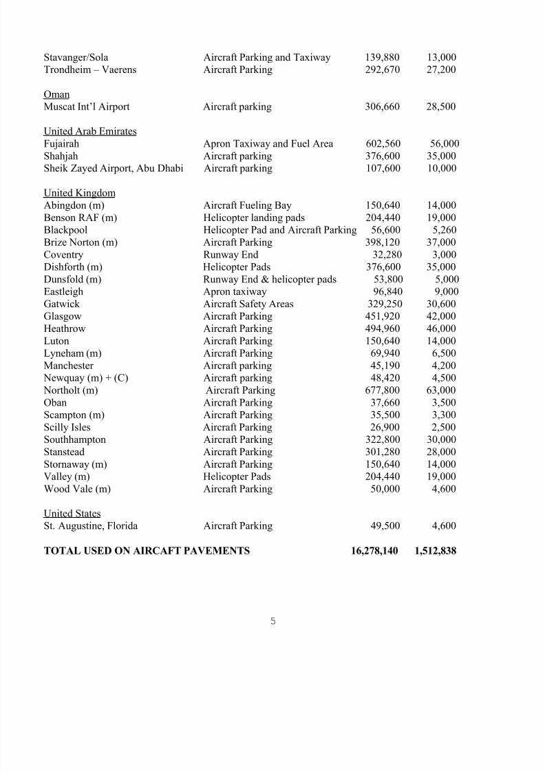
Concrete pavers bedded in sand (3, 4, 5, 6) provide a suitable wearing surface for aircraft pavements.Such pavements have been in use at airports for several years. The following lists airfields with concrete
pavers in use as of 2012. A history of the technical evolution of the pavement system is provided in“Evolution of Interlocking Concrete Pavement s for Airfields” 28.
LOCATION (m) = military APPLICATION APPROXIMATE AREAsf m 2
AustraliaRAAF Base Pearce – RSAF (m) Apron Parking 427,170 39,700RAAF Base Tindal (m) Apron Parking and Maritime OLAs 227,100 21,108RAAF Base Scherger (m) General Purpose Apron Parking 302,360 28,100Cairns Aircraft Apron 645,600 60,000Thevenard Island, Western Aus. Runway & Apron parking 280,000 26,000
BangladeshHazrat Shajalal Airport Cargo handling area 188,300 17,500
British West IndiesCayman Brac Aircraft Parking 9,700 900Grand Cayman Aircraft Apron 105,450 9,800
Hong KongChek Lap Kok Int’l Airport Aircraft Parking 5,380,000 500,000
IsraelBen Gurion Int'l Aircraft Parking 430,400 40,000Israel Aircraft Industries Aircraft Parking 75,320 7,000
KenyaJomo Kenyatta Aircraft Parking 609,500 56,650
MalaysiaSubang, Aircraft Apron 731,600 68,000Tanjong Manis Aircraft apron 80,700 7,500
New ZealandChristchurch Aircraft Apron 42,180 3,920Wellington Aircraft Apron 16,140 1,500
NorwayKrisiansand – Kjevic Aircraft Parking 71,550 6,650Oslo – Fornebu Aircraft Parking 13,450 1,250
8/10/2019 Us Airfield Manual 2012
http://slidepdf.com/reader/full/us-airfield-manual-2012 9/62
5
Stavanger/Sola Aircraft Parking and Taxiway 139,880 13,000Trondheim – Vaerens Aircraft Parking 292,670 27,200
OmanMuscat Int ’l Airport Aircraft parking 306,660 28,500
United Arab EmiratesFujairah Apron Taxiway and Fuel Area 602,560 56,000Shahjah Aircraft parking 376,600 35,000Sheik Zayed Airport, Abu Dhabi Aircraft parking 107,600 10,000
United KingdomAbingdon (m) Aircraft Fueling Bay 150,640 14,000Benson RAF (m) Helicopter landing pads 204,440 19,000Blackpool Helicopter Pad and Aircraft Parking 56,600 5,260Brize Norton (m) Aircraft Parking 398,120 37,000Coventry Runway End 32,280 3,000
Dishforth (m) Helicopter Pads 376,600 35,000Dunsfold (m) Runway End & helicopter pads 53,800 5,000Eastleigh Apron taxiway 96,840 9,000Gatwick Aircraft Safety Areas 329,250 30,600Glasgow Aircraft Parking 451,920 42,000Heathrow Aircraft Parking 494,960 46,000Luton Aircraft Parking 150,640 14,000Lyneham (m) Aircraft Parking 69,940 6,500Manchester Aircraft parking 45,190 4,200
Newquay (m) + (C) Aircraft parking 48,420 4,500 Northolt (m) Aircraft Parking 677,800 63,000
Oban Aircraft Parking 37,660 3,500Scampton (m) Aircraft Parking 35,500 3,300Scilly Isles Aircraft Parking 26,900 2,500Southhampton Aircraft Parking 322,800 30,000Stanstead Aircraft Parking 301,280 28,000Stornaway (m) Aircraft Parking 150,640 14,000Valley (m) Helicopter Pads 204,440 19,000Wood Vale (m) Aircraft Parking 50,000 4,600
United StatesSt. Augustine, Florida Aircraft Parking 49,500 4,600
TOTAL USED ON AIRCAFT PAVEMENTS 16,278,140 1,512,838

8/10/2019 Us Airfield Manual 2012
http://slidepdf.com/reader/full/us-airfield-manual-2012 10/62
6
═════════════════════════════════════════════════════════════════════════════
CHAPTER IV: ATTRIBUTES AND SELECTION CRITERIA
The pavement designer requires a working knowledge of different pavement materials to ensureselection of an appropriate pavement system. The selection should be based on evaluation of:
operational requirements (i.e. safety and reliability) environmental and climatic considerations constructability and operational disruption during the construction process structural requirements (i.e. aircraft loading) construction budget maintenance requirements cost-effectiveness
This chapter describes the attributes of concrete pavers, such that the pavement designer can makean informed decision on the appropriateness of concrete pavers for a particular application. Chapter VII
presents detailed information on computing the life cycle cost of pavements constructed with concrete paver(s).
4.1 Operational Requirements Airports represent a unique environment where concerns for operational safety are paramount. The
pavement systems used must meet stringent requirements to ensure that safety and reliability are notcompromised. In this regard, concrete pavers have demonstrated proven performance for a wide variety ofairport applications.
When designing an airport pavement, particular attention must be given to: surface stability resistance to fuels, hydraulics oils, and de-icing chemicals resistance to static loading skid resistance rideability
4.1.1 SURFACE STABILITY.Jet aircraft are susceptible to damage from loose material drawn into engine intakes. Damage from
ingestion of materials, birds, etc. into jet engines or damage to the airframe is referred to as foreign objectdamage (FOD). It is essential that any surface does not produce FOD and that it remains intact. Concrete
pavers with chamfered edges and uniform joint spacing will reduce the probability of this situationdeveloping to unacceptable levels. Since the interlocking quality and stability of a concrete paver surface isalso dependent on the joint sand, uptake of the joint sand is eliminated by stabilization with sealants (7).
However, there are certain situations where pavers are not recommended at this time. The BritishMinistry of Defense, British Aerospace, PLC, and the U.S. Air Force have conducted tests on paversexposed to high velocity jet exhaust (8, 9, 10, and 11) . Although, the results of these experiments werefavorable, concrete pavers are not recommended in airport locations subject to full power or reverse thrust,such as runways or apron areas where aircraft "power-back" operations are conducted. However, based on
8/10/2019 Us Airfield Manual 2012
http://slidepdf.com/reader/full/us-airfield-manual-2012 11/62
7
past performance pavers should be considered for: static parking positions with "tug-in/tug-out" or low engine speed "power-in/power-out"
operations (excluding reverse engine thrust) low speed taxiways and taxi lanes
As discussed, these areas should be sealed to stabilize the joint sand and prevent its loss from occasional
high levels of jet blast.
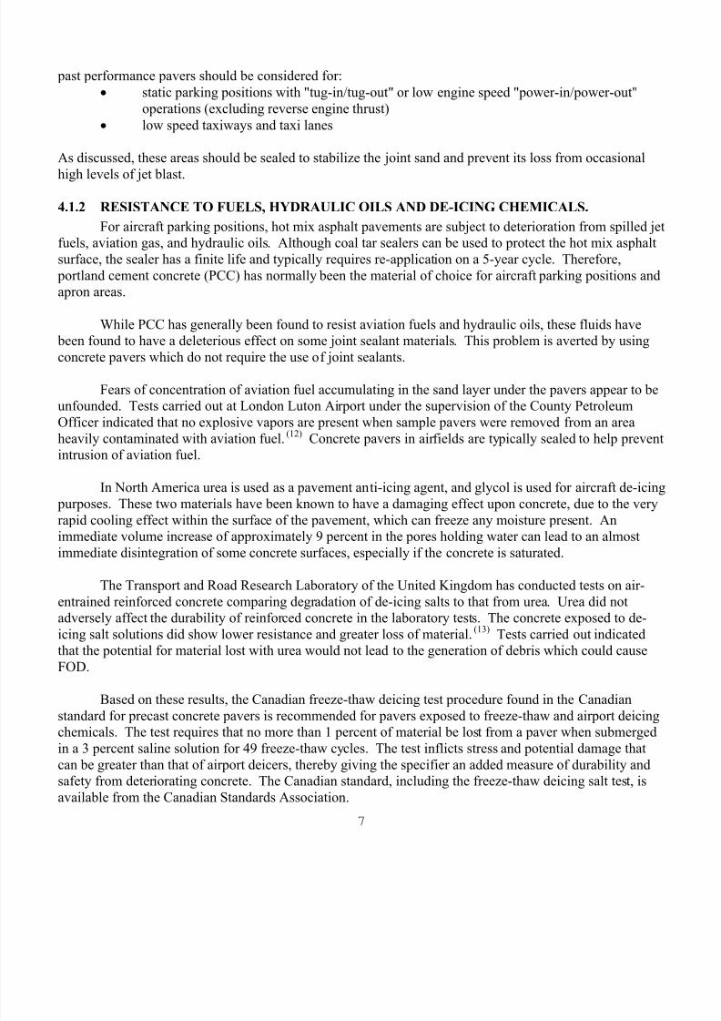
4.1.2 RESISTANCE TO FUELS, HYDRAULIC OILS AND DE-ICING CHEMICALS.For aircraft parking positions, hot mix asphalt pavements are subject to deterioration from spilled jet
fuels, aviation gas, and hydraulic oils. Although coal tar sealers can be used to protect the hot mix asphaltsurface, the sealer has a finite life and typically requires re-application on a 5-year cycle. Therefore,
portland cement concrete (PCC) has normally been the material of choice for aircraft parking positions andapron areas.
While PCC has generally been found to resist aviation fuels and hydraulic oils, these fluids have been found to have a deleterious effect on some joint sealant materials. This problem is averted by using
concrete pavers which do not require the use of joint sealants.
Fears of concentration of aviation fuel accumulating in the sand layer under the pavers appear to beunfounded. Tests carried out at London Luton Airport under the supervision of the County PetroleumOfficer indicated that no explosive vapors are present when sample pavers were removed from an areaheavily contaminated with aviation fuel. (12) Concrete pavers in airfields are typically sealed to help preventintrusion of aviation fuel.
In North America urea is used as a pavement anti-icing agent, and glycol is used for aircraft de-icing purposes. These two materials have been known to have a damaging effect upon concrete, due to the veryrapid cooling effect within the surface of the pavement, which can freeze any moisture present. An
immediate volume increase of approximately 9 percent in the pores holding water can lead to an almostimmediate disintegration of some concrete surfaces, especially if the concrete is saturated.
The Transport and Road Research Laboratory of the United Kingdom has conducted tests on air-entrained reinforced concrete comparing degradation of de-icing salts to that from urea. Urea did notadversely affect the durability of reinforced concrete in the laboratory tests. The concrete exposed to de-icing salt solutions did show lower resistance and greater loss of material. (13) Tests carried out indicatedthat the potential for material lost with urea would not lead to the generation of debris which could causeFOD.
Based on these results, the Canadian freeze-thaw deicing test procedure found in the Canadian
standard for precast concrete pavers is recommended for pavers exposed to freeze-thaw and airport deicingchemicals. The test requires that no more than 1 percent of material be lost from a paver when submergedin a 3 percent saline solution for 49 freeze-thaw cycles. The test inflicts stress and potential damage thatcan be greater than that of airport deicers, thereby giving the specifier an added measure of durability andsafety from deteriorating concrete. The Canadian standard, including the freeze-thaw deicing salt test, isavailable from the Canadian Standards Association.
8/10/2019 Us Airfield Manual 2012
http://slidepdf.com/reader/full/us-airfield-manual-2012 12/62
8
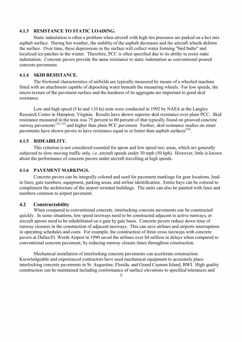
4.1.3 RESISTANCE TO STATIC LOADING.Static indentation is often a problem when aircraft with high tire pressures are parked on a hot mix
asphalt surface. During hot weather, the stability of the asphalt decreases and the aircraft wheels deformthe surface. Over time, these depressions in the surface will collect water forming "bird baths" andlocalized ice patches in the winter. Therefore, PCC is often specified due to its ability to resist static
indentation. Concrete pavers provide the same resistance to static indentation as conventional pouredconcrete pavements.
4.1.4 SKID RESISTANCE.The frictional characteristics of airfields are typically measured by means of a wheeled machine
fitted with an attachment capable of depositing water beneath the measuring wheels. For low speeds, themicro-texture of the pavement surface and the hardness of its aggregate are important to good skidresistance.
Low and high speed (5 kt and 110 kt) tests were conducted in 1992 by NASA at the LangleyResearch Center in Hampton, Virginia. Results have shown superior skid resistance over plain PCC. Skid
resistance measured in the tests was 75 percent to 80 percent of that typically found on grooved concreterunway pavements (14, 15) and higher than plain PCC pavement. Further, skid resistance studies on street
pavements have shown pavers to have resistance equal to or better than asphalt surfaces (16) .
4.1.5 RIDEABILITY.This criterion is not considered essential for apron and low speed taxi areas, which are generally
subjected to slow moving traffic only, i.e. aircraft speeds under 30 mph (50 kph). However, little is knownabout the performance of concrete pavers under aircraft travelling at high speeds.
4.1.6 PAVEMENT MARKINGS. Concrete pavers can be integrally colored and used for pavement markings for gear locations, lead-
in lines, gate numbers, equipment, parking areas, and airline identification. Entire bays can be colored tocompliment the architecture of the airport terminal buildings. The units can also be painted with lines andnumbers common to airport pavement.
4.2 ConstructabilityWhen compared to conventional concrete, interlocking concrete pavements can be constructed
quickly. In some situations, low speed taxiways need to be constructed adjacent to active runways, oraircraft aprons need to be rehabilitated on a gate by gate basis. Concrete pavers reduce down time ofrunway closures in the construction of adjacent taxiways. This can save airlines and airports interruptionsin operating schedules and costs. For example, the construction of three cross taxiways with concrete
pavers at Dallas/Ft. Worth Airport in 1990 saved the airlines over $4 million in delays when compared toconventional concrete pavement, by reducing runway closure times throughout construction.
Mechanical installation of interlocking concrete pavements can accelerate construction.Knowledgeable and experienced contractors have used mechanical equipment to accurately placeinterlocking concrete pavements in St. Augustine, Florida, and Grand Cayman Island, BWI. High qualityconstruction can be maintained including conformance of surface elevations to specified tolerances and

8/10/2019 Us Airfield Manual 2012
http://slidepdf.com/reader/full/us-airfield-manual-2012 13/62
9
consistent paver joint widths. Daily productivity per machine and crew ranges between 4000 sf. (400 m 2)and 6000 sf. (600 m 2). For detailed information on mechanized installation, see the Interlocking ConcretePavement Institute technical bulletins, Tech Spec 11, "Mechanized Installation of Interlocking ConcretePavement s”26 and Tech Spec 15, A Guide for the Construction of Mechanically Installed InterlockingConcrete Pavement s”27.
4.3 Maintenance and Reinstatement Pavements in busier airports may need to be repaired rapidly due to air operations limiting accesstime for work. When repairs to utilities or base are needed, concrete pavers can be removed and reused.They can also be rapidly reinstated in sub-freezing temperatures; however, the bedding sand and aggregate
base materials should not be frozen. Once laid and compacted, they can be put into immediate use. Unlikeasphalt or poured concrete, the continuity of the pavement is not damaged by cuts for access to utilities.Generally, pavements with pavers can be reinstated at approximately 25 percent less cost than concrete
pavements in a fraction of the time. For further information on reinstatement, see the Interlocking ConcretePavement Institute Tech Spec 6 technical bulletin, "Reinstatement of Interlocking Concrete Pavements". A
procedure for inspection and maintaining concrete pavers is included in Appendix C.
4.4 Rapid Removal of Surface Water and Snow Concrete pavers with chamfered edges are capable of rapid removal of surface water and areconsidered to be as good as, if not better than, conventional pavement in the removal of surface water.Observations have shown that after wetting, concrete pavers can dry faster than asphalt surfaces. Concrete
pavers can also be colored to absorb more of the sun's radiant energy to accelerate snow and ice melting.
Concrete pavers have demonstrated a record of snow removal capability by their use in airports inthe United Kingdom and Northern Europe. Snow plow blades do not catch on concrete pavers, providedthat each unit has a consistent thickness and that a smooth surface is achieved when installed. Smoothnessis achieved by an even surface on the base material and the bedding sand. Surface smoothness is furtherachieved during construction with compaction and final static proof rolling with an 8 ton to 10 ton (70 KN
to 90 KN) pneumatic tired roller.
Interlocking concrete pavements are typically sealed to stabilize the sand in the joints to preventFOD. Sealing also prevents water from seeping into the bedding sand. Should water infiltrate and saturatethe bedding sand, the water, when frozen, does not cause the pavers to heave. While there is movement in asaturated bedding sand layer when it freezes, it is minimal. Movement is typically a fraction of amillimeter. The sealer in the joints should be able to accommodate this small amount of movement without
breaking its bond with the sand or sides of the pavers.
The amount of movement in a frozen, saturated bedding sand layer of 1-inch (25 mm) can beestimated. When compacted, bedding sand may have a void space of 5 percent to 7 percent. If water
expands 9 percent when frozen, then the potential for heaving is 0.07 x 0.09 x 1-inch (25 mm) = 0.0063-inch (0.16 mm). Therefore, movement from freezing saturated bedding sand is small. The negligibleamount of movement will not allow paving units to protrude above the pavement surface and be damaged
by a passing snow plow blade.

8/10/2019 Us Airfield Manual 2012
http://slidepdf.com/reader/full/us-airfield-manual-2012 14/62
10
4.5 Climatic Considerations
4.5.1 FREEZE-THAW DURABILITY. Concrete pavers can be utilized under a wide variety of climatic conditions. Freeze-thaw resistant
pavers typically can be achieved by cement contents of 17 percent to 19 percent, absorption less than 4
percent, densities exceeding 142 lbs. cu. ft. (2,200 kg/m3), a low water cement ratio, and durable
aggregates. (17) If concrete pavers are exposed to consistent freeze-thaw cycles, a test for freeze-thaw by theCanadian Standards Association is recommended for assessing durability. The Canadian freeze-thaw testcan be found in the Canadian Standards Association specification CSA A231.2, "Precast Concrete Pavers".
4.5.2 RESISTANCE TO HIGH TEMPERATURES. Tests carried out on concrete pavers by British Aerospace PLC during investigations for the
feasibility of landing vertical take-off military aircraft (Harriers) on various surfaces have shown thatconcrete pavers are capable of withstanding temperatures up to 520 o C (1000 o F). Further, unlike thermo-viscous materials such as hot mix asphalt, the structural properties will not change with increasingtemperatures, thereby preventing static indentation at parking positions. Since concrete paver units aresmall, rapid increases in temperature do not cause shrinkage and spalling. This is an advantage over rigid
portland cement concrete which can spall and cause FOD as a result of a rapid increase in surfacetemperatures from jet blasts.
4.5.3 RESISTANCE TO THERMAL MOVEMENTS.Minor differential thermal movements in the underlying pavement bases do not produce visible
movement in the concrete pavers. This is due to the fact that the pavers and sand act as a flexible surfaceand individual pavers articulate without significant opening of the joints. Another advantage of concrete
pavers is their lighter color, which reduces the amount of heat absorbed into the underlying concrete, thusreducing thermal movement.
4.6 Use in Settlement Prone Areas The pavement designer is often required to design for difficult subsurface conditions, such as areas
prone to settlement. The preferred engineering solution is to mitigate the effects of settlement usingmethods such as surcharging. Due to the inherent variability in subsurface conditions, differentialsettlement, or secondary consolidation, often results after the completion of construction. While paverscannot prevent this condition, the pavers can be lifted, the base re-leveled, and the pavers re-instated,should post-construction differential settlement occur.
4.7 Structural Properties Concrete pavers provide a high strength operational surface. Typically, 3.125-inch (80 mm) thick
pavers can achieve a cube compressive strength of 8,000 psi to 10,000 psi (55 MPa to 69 MPa) after 28days, compared to a cube compressive strength of 6,000 psi (35 MPa) for poured concrete.
Concrete pavers are bedded on a coarse sand, and both the pavers and sand are compacted to refusal.The use of joint sand and the confinement from edge restrains provides interlock, enabling the pavers/sand
to function as a distinct structural layer. Nondestructive tests have shown that the pavers and bedding sand

8/10/2019 Us Airfield Manual 2012
http://slidepdf.com/reader/full/us-airfield-manual-2012 15/62
11
act as a structural layer with an elastic modulus of 450,000 psi (3082 MPa). (18) This exceeds the hotweather (i.e. 90 oF) modulus of hot mix asphalt, which is typically 150,000 psi to 300,000 psi (1370 MPa to2055 MPa).
4.8 Cost-Effectiveness
For areas where conventional concrete pavements have been the material of choice, concrete paverscan provide a viable alternative pavement structure. Areas include aircraft parking aprons, taxi lanes, andtaxiways, where resistance to fuel spills, static indentation, and rutting is required. These are areas wheresignificant economies in initial construction and life cycle costs are achievable. Savings in initialconstruction cost of 10 percent to 15 percent can be realized, when an interlocking concrete pavement iscompared to a conventional poured concrete pavement. Detailed information on pavement design
procedures for concrete pavers, and life cycle cost analysis methods follow in subsequent chapters.
4.9 FAA Airport Eligibility Airport pavements constructed with concrete paver surfaces are eligible for federal participation on
a case by case basis. The designer should check with the FAA Airport District Office (ADO) which has
jurisdiction for the particular airport project.
The construction of 260,000 sf. (26,000 sum.) of concrete pavers at Dallas/Ft. Worth InternationalAirport has received funding (retroactively) under the FAA Airport Improvement Program (AIP). The
project was determined eligible for funding in August 1992. Islip MacArthur Airport in Islip, New York,constructed rehabilitative inlay of concrete pavers over existing asphalt on two aircraft (MD-80) parkingareas. The 14,000 sf. (1300 sum.) project was funded through the FAA AIP.

8/10/2019 Us Airfield Manual 2012
http://slidepdf.com/reader/full/us-airfield-manual-2012 16/62
12
═════════════════════════════════════════════════════════════════════════════
CHAPTER V: STRUCTURAL DESIGN PROCEDURE --AIRCRAFT OVER 30,000 LBS. (13,600 kg) GROSS WEIGHT
5.1 Overview of Design Procedures The structural design procedure for aircraft with gross weights over 30,000 lbs. (13,600 kg) ismodeled directly on the FAA design procedures for flexible pavements contained in Section 2 of FAAAdvisory Circular 150/5320-6D. Application of the design procedures contained herein will provide a
pavement system at least as strong as a flexible pavement designed by the FAA method. The FAA (AAS-200) has concurred in the use of this method for airport pavements constructed with concrete pavers.
The design method for concrete pavers uses identical inputs as those used for the design of flexible pavement. These include:
subgrade strength (e.g. CBR); subbase/base materials (aggregate or stabilized);
traffic (selection of design aircraft and computation of equivalent annual departures); and evaluation of subgrade frost susceptibility and swelling potential.
The sets of flexible design curves contained in the Advisory Circular are then used to determine: total pavement thickness; thickness of surface plus base; and minimum base course thickness.
From the resulting thickness design, concrete pavers and sand are substituted for the hot mix asphalt layer,with all other layers remaining as designed for the flexible pavement. This would apply for both 4-inch(200 mm) and 5-inch (225 mm) (for wide body designs) hot mix asphalt thicknesses.
Other FAA design requirements for flexible pavements should be strictly adhered to as necessary.These include:
use of stabilized base for aircraft with gross loads over 100,000 lbs. (45,000 kg); minimum subgrade compaction requirements; treatment of swelling soils; thickness adjustments for seasonal frost or permafrost conditions; and thickness adjustments for high departure levels.
Since the FAA is committed to continued support of their pavement design methods, changes are periodically made to the design Advisory Circular based on application of research results and field
experience. Therefore, this manual will not attempt to duplicate the design curves and requirements of theAdvisory Circular. The reader is urged to obtain the latest edition of FAA Advisory Circular 150/5320-6and use this document as the basis for pavement designs using concrete pavers.
The latest edition of the FAA design guide is Advisory Circular 150/5320-6D, with corrections.Copies of 150/5320-6D (as well as other FAA publications) are available from:
8/10/2019 Us Airfield Manual 2012
http://slidepdf.com/reader/full/us-airfield-manual-2012 17/62
13
http://www1.faa.gov/arp . A computerized version of the flexible pavement design procedure is alsoavailable from the FAA web site.
5.2 Basis of Design Procedure Information on the design of concrete paver pavements has been presented by Knapton, (19,20) and
Rollings,(21)
and Anderton.(22)
This research established that concrete pavers and bedding sand have loadspreading characteristics greater than that of an equivalent thickness of asphalt.
Knapton also developed the British Ports Association Heavy Duty Pavement Design Manual. (20) This manual allows designers to proportion pavement course thicknesses for pavements subjected tocontainer handling equipment applying wheel loads of up to 30 tons onto concrete paver pavements. InEurope and North America, concrete pavers have been used to surface port pavements for many years. Thelargest container handling facility in the world, Europe Container Terminus, Rotterdam, the Netherlands, isentirely surfaced with over 11 million sf. (1 million m2) of concrete pavers.
Emery (3,4,5,and 6) has undertaken plate bearing tests on a bituminous surfaced aircraft pavement at
Luton. After removing the asphalt concrete, he undertook plate bearing tests directly on the underlying basecourse. He then installed concrete pavers and undertook a third set of plate bearing tests. His reportedresults indicate a 14 percent increase in strength when the asphalt concrete layer was replaced by concrete
pavers. In this manual, this increase is ignored so that the FAA curves can be used conservatively. In viewof the empirical nature of the FAA curves, it would be difficult to incorporate the additional structural
benefit of pavers into the design procedure. Pavements designed in accordance with this method areintended to provide a structural life of 20 years, requiring little maintenance if no major changes in forecasttraffic are encountered. Experience in heavy duty concrete paver pavements indicates that only minimalsurface maintenance will be required during this period.
The application of the research referred to above allows the FAA pavement design method (1) to be
modified to accommodate concrete pavers. The FAA pavement design method allows the thickness of the pavement courses to be proportioned and assumes that the pavements will be surfaced with either 4 inchesor 5 inches (200 mm or 225 mm) of asphalt concrete. By removing the asphalt concrete and substitutingconcrete pavers and sand, the resulting pavement will be at least as strong as the asphalt pavement thatwould have been produced using the FAA design charts.
5.3 Design Example The following example is based on the requirements and design charts contained in FAA Advisory
Circular 150/5320-6D.
5.3.1 AGGREGATE BASE DESIGN EXAMPLE.
Assume an airport pavement is to be designed for the following mix of aircraft. The subgrade designCBR = 6 percent.

8/10/2019 Us Airfield Manual 2012
http://slidepdf.com/reader/full/us-airfield-manual-2012 18/62
14
Gear Annual Maximum TakeoffAircraft Type Departures Weight (lbs.)────────────────────────────────────────────────────────────────────────────── 727-200 dual 3000 190,500737-200 dual 1200 115,500
747-100 double dual 1200 600,000tandem
First, the design aircraft has to be determined. This is the one requiring the thickest pavement forthe appropriate number of departures of the aircraft. Using the design charts, the following overall
pavement thicknesses are required:
Annual Overall PavementAircraft Departures Thickness (inch) ────────────────────────────────────────────────────────────────────────────── 727-200 3000 35.5737-200 1200 26747-100 1200 34.5
The 727-200 requires the greatest pavement thickness and is therefore the design aircraft. Thisaircraft has dual wheel landing gear so all traffic must be grouped into the dual wheel configuration. Theequivalent number of annual departures is calculated as follows:
Equivalent Wheel Design Equivalent AnnualDual Gear Load Wheel Load Departures Design
Aircraft Departures (lbs) (lbs) Aircraft ────────────────────────────────────────────────────────────────────────────── 727-200 3000 45,240 45,240 3000737-200 1200 27,430 45,240 250747-100 2040 35,625 45,240 865
TOTAL 4115
The dual wheel gear chart (Figure 3-3 of FAA Advisory Circular 150/5320-6D) shows that the total pavement thickness required is 36 inches (900 mm). Using a subbase CBR = 20, the thickness of surfaceand base from the design chart is 16 inches (400 mm) (i.e. 4 inches (100 mm) of hot mix asphalt (P-401)and 12 inches (300 mm) of aggregate base (P-209)). The use of the 12-inch (300 mm) base is confirmed bythe minimum base course (Table 3-4 of FAA Advisory Circular 150/5320-6D). Therefore, the pavementsection required is:
3.125 inches ( 80 mm) pavers1.25 inches ( 30 mm) bedding sand12 inches (300 mm) aggregate base (P-209)20 inches (500 mm) aggregate subbase (P-154)
8/10/2019 Us Airfield Manual 2012
http://slidepdf.com/reader/full/us-airfield-manual-2012 19/62
15
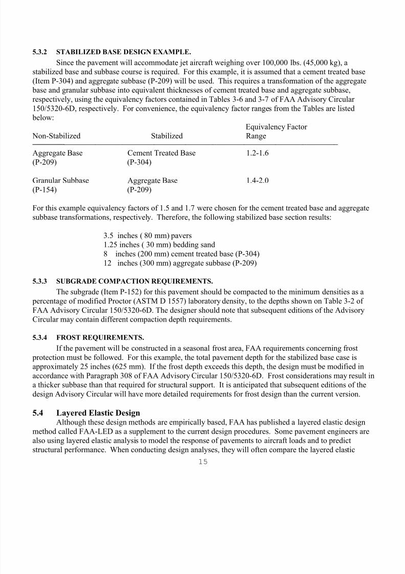
5.3.2 STABILIZED BASE DESIGN EXAMPLE. Since the pavement will accommodate jet aircraft weighing over 100,000 lbs. (45,000 kg), a
stabilized base and subbase course is required. For this example, it is assumed that a cement treated base(Item P-304) and aggregate subbase (P-209) will be used. This requires a transformation of the aggregate
base and granular subbase into equivalent thicknesses of cement treated base and aggregate subbase,
respectively, using the equivalency factors contained in Tables 3-6 and 3-7 of FAA Advisory Circular150/5320-6D, respectively. For convenience, the equivalency factor ranges from the Tables are listed below:
Equivalency Factor Non-Stabilized Stabilized Range
────────────────────────────────────────────────────────────────────────────── Aggregate Base Cement Treated Base 1.2-1.6(P-209) (P-304)
Granular Subbase Aggregate Base 1.4-2.0(P-154) (P-209)
For this example equivalency factors of 1.5 and 1.7 were chosen for the cement treated base and aggregatesubbase transformations, respectively. Therefore, the following stabilized base section results:
3.5 inches ( 80 mm) pavers1.25 inches ( 30 mm) bedding sand8 inches (200 mm) cement treated base (P-304)12 inches (300 mm) aggregate subbase (P-209)
5.3.3 SUBGRADE COMPACTION REQUIREMENTS. The subgrade (Item P-152) for this pavement should be compacted to the minimum densities as a
percentage of modified Proctor (ASTM D 1557) laboratory density, to the depths shown on Table 3-2 ofFAA Advisory Circular 150/5320-6D. The designer should note that subsequent editions of the AdvisoryCircular may contain different compaction depth requirements.
5.3.4 FROST REQUIREMENTS. If the pavement will be constructed in a seasonal frost area, FAA requirements concerning frost
protection must be followed. For this example, the total pavement depth for the stabilized base case isapproximately 25 inches (625 mm). If the frost depth exceeds this depth, the design must be modified inaccordance with Paragraph 308 of FAA Advisory Circular 150/5320-6D. Frost considerations may result ina thicker subbase than that required for structural support. It is anticipated that subsequent editions of thedesign Advisory Circular will have more detailed requirements for frost design than the current version.
5.4 Layered Elastic DesignAlthough these design methods are empirically based, FAA has published a layered elastic design
method called FAA-LED as a supplement to the current design procedures. Some pavement engineers arealso using layered elastic analysis to model the response of pavements to aircraft loads and to predictstructural performance. When conducting design analyses, they will often compare the layered elastic
8/10/2019 Us Airfield Manual 2012
http://slidepdf.com/reader/full/us-airfield-manual-2012 20/62
16
results to the FAA design results. FAA-LED is available from http://www.airporttech.tc.faa.gov/ .
Layered elastic design methods for airfield pavements are based on the theory that the pavementstructure reacts to loads as a multi-layered elastic system. Each layer is characterized by its elastic modulusand Poisson's ratio. Critical strains in the layers are computed for the range of predicted loads and subgrade
conditions. For flexible pavements, these are normally horizontal tensile strain at the bottom of the asphaltor stabilized base layer(s) and the vertical compressive strain at the top of the subgrade layer. Thecomputed strains are compared to limiting strain criteria, which are normally a function of layer strengthand the number of strain repetitions (i.e. coverages). Since the strength of the pavement materials areknown, pavement layer thicknesses are then selected that will yield strains that are less than or equal to thelimiting strains.
An elastic modulus of 450,000 psi (3082 MPa) and a Poisson's ratio of 0.3 should be used to modelthe composite paver/bedding sand layer when conducting layered elastic designs. This is based on researchconducted by the Concrete Paver Institute and other literature on the design of heavy duty pavements withinterlocking concrete pavers. (18) Further research in and adoption of layered elastic design methods may
show that some decrease in total pavement section thickness is possible with the use of a concrete paversurface as compared to a hot mix asphalt surface.
5.5 Construction Details Typical construction details for pavements to accommodate aircraft over 30,000 lbs. (13,600 kg) are
included in Appendix B.

8/10/2019 Us Airfield Manual 2012
http://slidepdf.com/reader/full/us-airfield-manual-2012 21/62
17
═════════════════════════════════════════════════════════════════════════════
CHAPTER VI: STRUCTURAL DESIGN -- LIGHT AIRCRAFTPAVEMENT
6.1 Application Concrete pavers can also be utilized for light aircraft and helicopter pavements (i.e. aircraft less than
30,000 lbs. (13,600 kg)). A typical application would be for an aircraft parking apron, where fuel spills can be a problem or where high tire corporate jet aircraft can cause static indentation on hot mix asphaltsurfaces.
6.2 Overview of Design Method The structural design procedure for light aircraft is similar to that used for aircraft over 30,000 lbs.
(13,600 kg). The design is based on the FAA flexible design procedure for light aircraft contained inChapter 5 of FAA Advisory Circular 150/5320-6. As with the heavy load design, the paver/sand layer issubstituted for the hot mix asphalt surface. Design inputs are identical to those used for the flexible
pavement design case.
However, since the FAA standard for light load flexible pavements is based on a 2-inch (50 mm)thickness of hot mix asphalt, a direct substitution with a 4-inch to 4.5 inch (100 mm to 115 mm) paver/sandlayer may result in an overdesign. Therefore, it is recommended that the subbase thickness be decreased toaccount for the additional 2+ inches (50+ mm) of pavers/sand. An equivalent factor of 1.5:1 is suggested,i.e. the subbase thickness can be decreased 3 inches (75 mm) to account for the additional thickness ofsurfacing. It is recommended that the FAA's minimum base thicknesses, required by Chapter 5 of FAAAdvisory Circular 150/5320-6D, remain unchanged.
Therefore, the design procedure would involve the following steps: Select design aircraft Select subgrade CBR Determine total pavement thickness from Figure 5-2 of FAA Advisory Circular 150/5320-
6D. Determine thickness of surface and base by using the CBR = 20 line, or other subbase CBR
to fit the design case Determine the thickness of the base layer by subtracting 2 inches (50 mm) from the
thickness of surface plus base. This is the thickness of base that would be required with a 2-inch (50 mm) asphalt surface.
Decrease the thickness of the subbase course by 3 inches (75 mm) to account for theadditional thickness of the paver/sand layer.
6.3 Design Example The following design example is based on the FAA flexible design procedures for light aircraft
contained in Chapter 5 of FAA Advisory Circular 150/6320-6D. Although subsequent editions of theAdvisory Circular may contain different design charts or other requirements, the basic design procedureoutline above should still apply.
8/10/2019 Us Airfield Manual 2012
http://slidepdf.com/reader/full/us-airfield-manual-2012 22/62
18
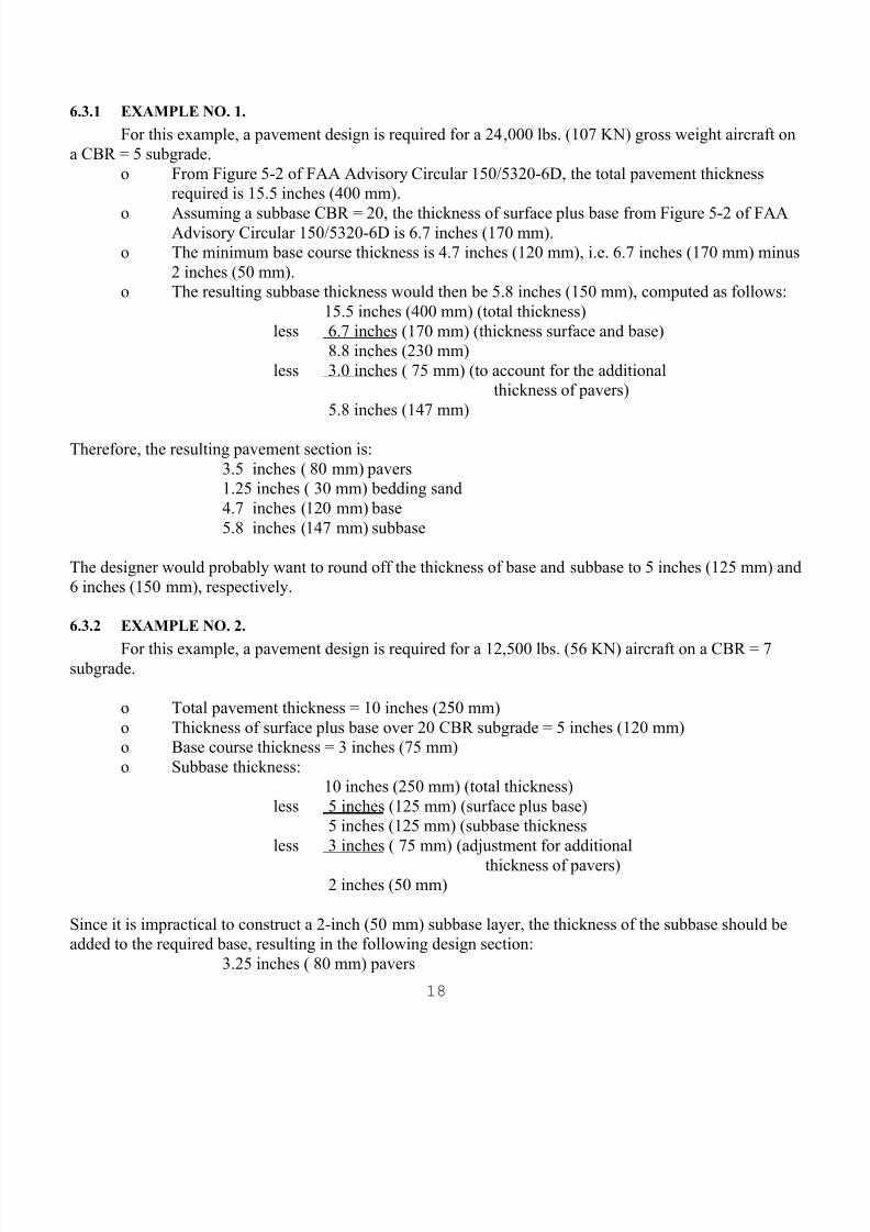
6.3.1 EXAMPLE NO. 1.
For this example, a pavement design is required for a 24,000 lbs. (107 KN) gross weight aircraft ona CBR = 5 subgrade.
o From Figure 5-2 of FAA Advisory Circular 150/5320-6D, the total pavement thicknessrequired is 15.5 inches (400 mm).
o Assuming a subbase CBR = 20, the thickness of surface plus base from Figure 5-2 of FAAAdvisory Circular 150/5320-6D is 6.7 inches (170 mm).o The minimum base course thickness is 4.7 inches (120 mm), i.e. 6.7 inches (170 mm) minus
2 inches (50 mm).o The resulting subbase thickness would then be 5.8 inches (150 mm), computed as follows:
15.5 inches (400 mm) (total thickness)less 6.7 inches (170 mm) (thickness surface and base)
8.8 inches (230 mm)less 3.0 inches ( 75 mm) (to account for the additional
thickness of pavers)5.8 inches (147 mm)
Therefore, the resulting pavement section is:3.5 inches ( 80 mm) pavers1.25 inches ( 30 mm) bedding sand4.7 inches (120 mm) base5.8 inches (147 mm) subbase
The designer would probably want to round off the thickness of base and subbase to 5 inches (125 mm) and6 inches (150 mm), respectively.
6.3.2 EXAMPLE NO. 2.
For this example, a pavement design is required for a 12,500 lbs. (56 KN) aircraft on a CBR = 7subgrade.
o Total pavement thickness = 10 inches (250 mm)o Thickness of surface plus base over 20 CBR subgrade = 5 inches (120 mm)o Base course thickness = 3 inches (75 mm)o Subbase thickness:
10 inches (250 mm) (total thickness)less 5 inches (125 mm) (surface plus base)
5 inches (125 mm) (subbase thicknessless 3 inches ( 75 mm) (adjustment for additional
thickness of pavers)2 inches (50 mm)
Since it is impractical to construct a 2-inch (50 mm) subbase layer, the thickness of the subbase should beadded to the required base, resulting in the following design section:
3.25 inches ( 80 mm) pavers

8/10/2019 Us Airfield Manual 2012
http://slidepdf.com/reader/full/us-airfield-manual-2012 23/62
19
1.25 inches ( 30 mm) bedding sand5.0 inches (125 mm) base
6.4 Construction Details Typical construction details for light aircraft pavement are included in Appendix B. The designer
should carefully review each applicable detail and make modifications as needed to meet site specificdesign and construction requirements.

8/10/2019 Us Airfield Manual 2012
http://slidepdf.com/reader/full/us-airfield-manual-2012 24/62
20
═════════════════════════════════════════════════════════════════════════════
CHAPTER VII: PAVEMENT REHABILITATION WITHCONCRETE PAVERS
Most airport pavements in use today were constructed 20 years or more ago. In many cases, theyhave been subjected to increased aircraft weights and frequencies of operation which often exceeded theoriginal design assumptions. Here, the pavement may require strengthening to accommodate the forecastedtraffic over the next design period.
In other cases, although the pavement may be structurally adequate, surface conditions may havedeteriorated to the point where debris is generated creating a potential FOD hazard. Here, rehabilitationwould be required to improve the safety and reliability of the functional surface.
Concrete pavers can be used for either structural (i.e. strengthening) or functional (i.e. non-structural) rehabilitation of airport pavements. As with new construction, the pavers are modeled as a hot
mix asphalt material when performing structural overlay computations, using the procedures detailed inChapter 4 of FAA Advisory Circular 150/5320-6D. Pavers are appropriate for rehabilitating both flexibleand rigid pavements.
The computational sequence involves: evaluate the existing pavement conditions; determine whether structural or functional rehabilitation is required; design the overlay thickness for structural rehabilitation (i.e. strengthening); determine the amount and type of pre-requisite base pavement repairs prior to construction
of the overlay.
7.1 Evaluation The first requirement is to evaluate the functional and structural condition of the existing pavement.FAA pavement evaluation procedures are detailed in Chapter 6 of FAA Advisory Circular 150/6320-6D.
As described in the Advisory Circular, the process involves: Records Research - compilation of as-built drawings, prior reports, traffic data, and etc. Site Inspection - examination of drainage conditions and overall pavement condition, noting
problem areas and planning for more detailed field investigations. Conventional Testing - field and laboratory tests to determine layer thickness, subgrade
strength (i.e. CBR or k), the condition, strength, and suggested equivalencies for existingmaterials, and identification of special conditions (e.g. frost effects, swelling soils, reactiveaggregates, etc.).
Nondestructive Testing - dynamic tests to measure overall pavement stiffness, identify patterns of variability in support conditions, and evaluate the strength of pavement layersand subgrade soils. FAA Advisory Circular 150/5370-11, "Use of Nondestructive TestingDevices in the Evaluation of Airport Pavements" (23) contains guidance on nondestructivetesting; however, when approved by the FAA, procedures different from those contained inFAA Advisory Circular 150/5370-11 may be used.

8/10/2019 Us Airfield Manual 2012
http://slidepdf.com/reader/full/us-airfield-manual-2012 25/62
21
Pavement Condition Survey - visual survey to determine the Pavement Condition Index(PCI) and/or Structural Condition Index (SCI), and to generate quantities for repair of
pavement distress. FAA Advisory Circular 150/5380-6A, "Guidelines and Procedures forMaintenance of Airport Pavements" (24) contains detailed information on conducting
condition surveys and other information on the PCI concept. Other Tools - other methods, such as ground penetrating radar or infrared thermography may be used to identify voids, delamination, or subsurface anomalies.
Structural Evaluation - determination of the structural adequacy of the existing pavement toaccommodate forecasted aircraft loading, as described in Chapter 6 of FAA AdvisoryCircular 150/5320-6D.
The evaluation process should culminate in a detailed evaluation report which describes theanalyses, test methods and results, findings, and recommendations. The report should document:
the functional surface condition in terms of the PCI; the load carrying capacity with respect to the demand forecast; and
whether rehabilitation requirements are driven by structural or functional conditions, or both.
7.2 Structural Rehabilitation If structural rehabilitation and strengthening is required, the designer should use the flexible overlay
procedures contained in Chapter 4 of FAA Advisory Circular 150/5320-6D for flexible or rigid pavements,as appropriate. Required inputs include:
subgrade strength (CBR or k); existing pavement thickness; layer equivalencies for flexible pavement layers based on the condition of each layer; flexural strength of concrete layers; and forecasted traffic.
7.2.1 OVERLAY OF FLEXIBLE PAVEMENT. The overlay design procedure for flexible pavements is based on the structural deficiency approach.
In other words, the existing pavement is compared to what is needed for a new pavement and anydeficiency is made up in the overlay.
As discussed previously, pavers/sand can be conservatively substituted for hot mix asphalt (HMA)on an inch for inch (mm for mm) basis. Thus, if the overlay requirement is 4.5 inches (115 mm) or less,concrete pavers and sand can be substituted for the HMA layer. If the overlay thickness exceeds 4.5 inches(115 mm), the additional thickness can be made up with hot mix asphalt (FAA Item P-401). When needed,the minimum thickness of the HMA layer should normally be 2 inches (50 mm) or greater, depending onthe maximum aggregate size of the P-401 mix.
If the surface is deteriorated, then pre-requisite distress repairs (e.g. crack sealing, full or partialdepth patches, milling, etc.) should be accomplished prior to construction of the paver or paver/HMAoverlay. Normally, a geotechnical fabric should be placed on the top of the asphalt layer prior to placing
bedding sand to prevent the migration of bedding sand into cracks in the asphalt layer. Steel angle or

8/10/2019 Us Airfield Manual 2012
http://slidepdf.com/reader/full/us-airfield-manual-2012 26/62
22
concrete edge restraints should be constructed where required.
7.2.2 FLEXIBLE PAVEMENT EXAMPLE. To illustrate the procedure for designing a concrete paver overlay on an existing flexible pavement,
assume the following input conditions:
Subgrade CBR = 7 Subbase CBR = 15 HMA surface thickness = 4 inches (100 mm) Aggregate base thickness = 6 inches (150 mm) Subbase thickness = 10 inches (250 mm) Total pavement thickness = 20 inches (500 mm) 3000 annual departures of a dual wheel aircraft at 140,000 lbs. (623 KN)
From the design charts in Chapter 3 of FAA Advisory Circular 150/5320-6D the required pavementthickness for the input condition is:
HMA surface = 4 inches (100 mm)
Aggregate base thickness = 12 inches (300 mm) Subbase thickness = 11 inches (280 mm)
Comparing the required and existing sections, the base course is deficient by 6 inches (150 mm) andthe subbase is deficient by 1-inch (25 mm). Assuming that the condition survey and materials investigationfound that the existing HMA surface can be converted to base using an equivalency of 1:5 to 1, the exitingHMA layer can be transformed to 6 inches (150 mm) of aggregate base. This leaves a 4-inch (100 mm)deficiency in HMA surface (from the conversion of the existing surface to base) and a 1-inch (25 mm)deficiency in subbase. Using a conversion of 2:1, the 1-inch (25 mm) subbase deficiency would relate to a.5-inch (12 mm) deficiency in HMA. Therefore, the overlay requirement for the pavement is 4.5 inches(115 mm) of HMA.
As discussed previously, the paver/sand layer can be substituted for HMA on an inch for inch (mmfor mm) basis. Since the existing asphalt surface is probably cracked, a layer of geotextile should be placed
prior to constructing the bedding sand layer. Also, any prerequisite distress repairs should be accomplished prior to overlay construction.
For the preceding example, assume that the HMA overlay worked out to be 7 inches (175 mm).Using a nominal thickness of 4.5 inches (115 mm) for the paver/sand layer, an additional layer of 2.5 inches(60 mm) of HMA would be required prior to construction of the paver and sand layer.
7.2.3 OVERLAY OF RIGID PAVEMENT. The overlay design procedure for rigid pavements is also based on a thickness deficiency approach,
with the thickness of pavers/sand substituted inch for inch (mm for mm) for HMA. The formula forcomputing overlay thickness is as follows:
t = 2.5 (Fh d - C bhe)where:
t = thickness of HMA overlay, inches (mm)

8/10/2019 Us Airfield Manual 2012
http://slidepdf.com/reader/full/us-airfield-manual-2012 27/62
23
F = a factor which controls the degree of cracking in the base rigid pavementhd = thickness of new rigid pavement required for design conditions, inches (mm).
Use the exact value for h d; do not round off. In calculating h d use the k valueof the existing foundation and the flexural strength of exiting concrete asdesign parameters.
C b = a condition factor which indicates the structural integrity of the existing rigid pavement. Value ranges from 1.0 to 0.75.he = thickness of existing rigid pavement, inches (mm)
As with overlays for flexible pavement, if the required thickness of HMA is greater than 4.5 inches(115 mm), the difference between the required thickness and the nominal thickness of pavers/sand can bemade up with HMA. Again, a minimum HMA thickness of 2 inches (75 mm) is recommended.
The designer is cautioned that special treatments may be required when constructing a paver/sandoverlay on existing concrete pavements, including:
use of geotechnical fabric to prevent loss of bedding sand into concrete joints and cracks;
possible jointing of the pavers over expansion joints; improvement of joint efficiency (i.e. load transfer), of the existing slabs using mudjackingtechniques or proprietary load transfer devices, as required; and
accomplishing prerequisite distress repair (e.g. joint resealing, crack sealing, patching, etc.).
If the condition of the existing rigid pavement is very poor, i.e., extensive structural cracking, jointfaulting, "D" cracking etc. consideration should be given to using the "crack and seat" technique. The crackand seat technique involves purposely breaking the existing rigid pavement and then rolling the broken
pieces to firmly seat them in the foundation. A hot mix asphalt layer is then placed over the pavement.This type of section is designed as a flexible pavement treating the broken rigid pavement as base course. Ifconcrete pavers are to be used, the thickness of the paver/sand layer is deducted from the required thickness
of HMA. A geotextile fabric under the bedding sand is recommended for this type of construction. Furtherinformation on cracking and seating is given in Report DOT/FAA/PM-87/4, "Performance of Cracked andSeated Rigid Pavements". (25)
7.2.4 RIGID PAVEMENT EXAMPLE. To illustrate the procedures for designing a concrete paver overlay on a existing rigid pavement,
assume the following input conditions: Existing slab thickness = 12 inches (300 mm) Flexural strength of concrete = 725 psi (5 MPa) Foundation modulus (k) = 300 psi (81.6 MPa/m) Condition Factor (C b) = 0.95
3,000 annual departures of a dual wheel aircraft weighing 180,000 lbs. (801 KN)
The initial step is to compute the equivalent slab thickness for the input conditions, using theappropriate design chart in Section 3 of Chapter 3 of FAA Advisory Circular 150/5320-6D. For dual wheelaircraft, this thickness is found to be 13.9 inches (350 mm). The F factor for the annual traffic and subgrademodulus is found to be 0.93. Applying the overlay formula given in Section 7.2.3, above, yielded:
8/10/2019 Us Airfield Manual 2012
http://slidepdf.com/reader/full/us-airfield-manual-2012 28/62
24
t = 2.5 (0.93 x 13.9 - 0.95 x 12)= 3.82 inches (97 mm)
This would equate to a thickness of 1.25 inches (30 mm) of bedding sand and 3.125 inches (80 mm) of
concrete pavers.
For the above example, suppose that the required HMA overlay thickness was 8 inches (200 mm).In this case, a 3.5-inch (90 mm) HMA layer would be constructed prior to construction of the paver/sandlayer. For both examples, a layer of geotextile fabric is recommended prior to placing the bedding sandlayer.
7.3 Nonstructural Overlay In some instances, a pavement may be structurally adequate for the forecasted traffic, but its surface
condition may have deteriorated to the point where operational safety or reliability is compromised. Inthese instances, an overlay, or inlay, with concrete pavers may be an appropriate rehabilitation option. An
example would be a low speed taxiway in need of functional surface improvement, or an existing asphaltapron in need of a hard surface to eliminate static indentation and fuel spill damage.
Where grade considerations are not a factor, an overlay with pavers may be considered. However,where grade constraints make an overlay impractical, such as may be the condition for an apron area, then,either surface reconstruction with pavers or an inlay (e.g. remove sufficient surface thickness to allow forthe paver/sand layer) should be considered, depending on the thickness of the surface layer.
As with structural overlays, pre-requisite base pavement repairs should be accomplished and ageotextile fabric should be placed prior to constructing the paver/sand layer.
7.4 Typical Details Typical construction details for pavement rehabilitation using interlocking concrete pavers areincluded in Appendix B. The designer should carefully review each applicable detail and makemodifications as needed to meet site specific design and construction requirements.
8/10/2019 Us Airfield Manual 2012
http://slidepdf.com/reader/full/us-airfield-manual-2012 29/62
25
═════════════════════════════════════════════════════════════════════════════
CHAPTER VIII: LIFE CYCLE COST ANALYSIS
As a pre-requisite for federal funding, the FAA will normally require that various pavementconstruction alternatives be considered, and the life cycle cost of each alternative computed and compared.The life cycle cost concept is a means to compare the total cost of various construction alternatives. Thecomponents of the life cycle cost typically include:
o initial construction costo periodic maintenanceo time value of money (i.e. interest rate)
Since some of the cost components, e.g. periodic maintenance, will be incurred at a future date, these futurecosts must be discounted to a present value using an appropriate interest rate, and added to the initialconstruction cost in order to compare alternatives.
A detailed procedure for computing life cycle cost is contained in the Appendix to FAA AdvisoryCircular 150/5320-6D, Appendix 1. The FAA recommends that the present worth of each alternative becompared using a discount rate (i.e. interest rate) of 4 percent. There are also several computer programsavailable for computing life cycle cost, including the Economic Analysis program included in the DataAnalysis Programs portion of MICROPAVER.
Application of life cycle cost analysis can best be demonstrated by the following example.
8.1 Pavement Design Portland cement concrete (PCC) and concrete paver pavements are to be designed and life cycle costs
compared for a new apron based on the following input conditions:o subgrade CBR = 10o subbase CBR = 20o PCC flexural strength = 715 psi (4.9 MPa)o subgrade k = 200 pci (54 MPa/m)o 3000 annual departures of a dual wheel aircraft at 200,000 lbs. (890 KN)
Since the pavement will serve aircraft with gross weights over 100,000 lbs. (440 KN), a stabilized basewill be required for each alternative. For this example, it is assumed that a cement treated base (CTB), FAAItem P-304, and aggregate subbase, FAA Item P-209, will be used for both pavements. For the interlockingconcrete paver pavement, an equivalency of 1.5:1 was used for transforming aggregate base (P-209) to cementtreated base (P-304) and an equivalency of 1.7:1 was used for transforming granular subbase (P-154) toaggregate base (P-209). For the PCC option, the use of cement treated base and aggregate subbase is reflectedin adjustments to the subgrade k made during the design computations.
For the input conditions presented above, the design alternatives are:

8/10/2019 Us Airfield Manual 2012
http://slidepdf.com/reader/full/us-airfield-manual-2012 30/62
26
PAVERS PCC3.125 inches ( 80 mm) Pavers 14 inches (360 mm) PCC1.25 inches ( 30 mm) Bedding Sand 6 inches (150 mm) CTB8 inches (200 mm) CTB 6 inches (150 mm) Aggregate Base6 inches (150 mm) Aggregate Subbase
Since the pavers are to be constructed on a cement treated base (CTB), geotextile fabric should be placed over the CTB to prevent possible loss of bedding sand through shrinkage cracks in the CTB. Further,the paver surface should be sealed to prevent the erosion of jointing sand from jet blast.
8.2 Initial Construction Costs Using typical construction cost data (in 2002 dollars), the initial construction cost (per square yard) of
each alternate is computed in Table 1, "Construction Cost". Pavement costs do not include subgrade gradingand compaction, which are considered equal for each option.
The construction cost estimate for concrete pavers was taken from bid prices for concrete pavers at
airports in Texas and Florida in 2003. Actual costs for pavers, as well as PCC pavement, may vary dependingon geographic location, project size, and site specific conditions. However, the costs presented are believed to be reasonable for the purpose of comparing the relative costs of the two alternatives.
TABLE 1: CONSTRUCTION COST
INTERLOCKING PORTLAND CEMENTCONCRETE PAVEMENTS - $/s.y. CONCRETE--------------------------------------- $/s.y.
Pavers/Bedding Sand $27.00 14 inches (350 mm) PCC $47.00Sealer 1.50 6 inches (150 mm) CTB 9.00Geotextile 1.50 6 inches (150 mm) AGBS 6.508 inches (200 mm) CTB 12.00 $62.506 inches (150 mm) AGBS 6.00
$48.50
PCC = Portland Cement ConcreteCTB = Cement Treated BaseAGBS = Aggregate Subbase
Note: To convert $/s.y. to $/s.m. multiply values by 1.2
8.3 Maintenance Costs Since pavement maintenance costs are normally included in an airports overall operations and
maintenance budget, it is often difficult to identify specific annual and periodic maintenance costs for airport pavements. Therefore, some judgment is inherent in estimating these costs.
For the example presented in this section, assumptions on period maintenance activities and costs foreach alternative are presented in Table 2, "Maintenance Activities and Costs".

8/10/2019 Us Airfield Manual 2012
http://slidepdf.com/reader/full/us-airfield-manual-2012 31/62
27
TABLE 2: MAINTENANCE ACTIVITIES AND COSTS
CONCRETE PAVERS
Activity Frequency Costs/s.y.Reapply sealant 5 years $0.15Replace pavers 5 years $0.45
PORTLAND CEMENT CONCRETEActivity Frequency Costs/s.y.
Reseal joints 10 years $0.40Patch and crack seal 5 years $0.50
8.4 Present Worth From FAA Advisory Circular 150/5320-6D, the basic equation for determining present worth is:
Where:
PW = Present WorthC = Present cost of initial construction or rehabilitation activityMi = Cost of the ith maintenance or rehabilitation alternative in terms of present costs, i.e.
constant dollarsr = Discount rate (4 percent suggested)ni = Number of years from the present of the ith maintenance or rehabilitation activityS = Salvage value at the end of the analysis period.z = Length of analysis period in years (20 years suggested)
The term
is commonly called the single payment present worth factor in most engineering economictextbooks. From a practical standpoint, if the difference in the present worth of costs betweentwo designs or rehabilitation alternatives is 10 percent or less, it normally assumed to beinsignificant and the present worth of the two alternatives can be assumed to be the same.
For this example, the salvage values for each alternative are assumed to be zero.
Using the input data developed above, the present worth of the two alternatives were computed to be:

8/10/2019 Us Airfield Manual 2012
http://slidepdf.com/reader/full/us-airfield-manual-2012 32/62

8/10/2019 Us Airfield Manual 2012
http://slidepdf.com/reader/full/us-airfield-manual-2012 33/62
29
═════════════════════════════════════════════════════════════════════════════
CHAPTER IX: REFERENCES
(1) Airport Pavement Design and Evaluation, Department of Transportation, Federal AviationAdministration, Advisory Circular (AC) 150/5320-6D, Washington, D.C.; December 1978.
(2) Correspondence dated March 18, 1988, from Robert Bates, Manager, Engineering and SpecificationDivision, Office of Airport Safety and Standards, Federal Aviation Administration, Washington, D.C.
(3) Emery, J.A., "The Use of Concrete Pavers for Aircraft Pavements" Proceedings, Institution of CivilEngineers, Part 1, Volume 77, I.C.E., Great George Street, London England, Paper No. 8841-188, 80;April 1986, pp. 451-464.
(4) Emery, J.A., "The Design of Concrete Paver Aircraft Pavements" in Proceedings of the ThirdInternational Conference on Concrete Block Paving, Pavitalia, Rome, Italy; May 17-19, 1988, pp. 178-187.
(5) Emery, J.A., "Concrete Pavers for Aircraft Pavement Surfaces", American Society of Civil Engineers,Journal of Transportation Engineering, Volume 112, No. 6, Paper No. 21041; November 1966.
(6) Emery, J.A., "Concrete Paver Paving for Aircraft Hard Standings and Turning Areas", in Proceedingsof the Second International Conference on Concrete Block Paving, Delft University, The Netherlands,CBP c/o KLVL, 2500 GK, The Hague; April 1984, pp. 176-182.
(7) Emery, J.A., "Stabilization of Jointing Sand in Paver Paving", American Society of Civil Engineers,Journal of Transportation Engineering, Volume 119, No. 1, January/February 1993, Paper No. 235, pp.142-148.
(8) "Air Force Test Pavers with Successful Results", Pavers, Volume 3, No. 3, Concrete Paver Institute,Herndon, VA, July 1992, p. 3.
(9) Edwards, G., "Ground Erosion Trial Element Paving (under) Shoeburgness Peagasus 2A TetheredHarrier", Military Vehicles and Engineering Establishment, UK Ministry of Defense, London,England, 1983.
(10) Emery, J.A., "Erosion of Jointing Sand from Concrete Paver Paving", in Proceedings, FourthInternational Conference on Concrete Block Paving, Auckland, New Zealand, February, 1992, Volume2, pp. 295-299.
(11) Knott, P., et al, "An Experimental Investigation of the Ability of Polyester Resin Based Materials toWithstand Erosion from a Heated Jet Exhaust", British Aerospace, PLC, Report No. BAe-WMT-R-RES-000-10031, Lancashire, England, 1982.
(12) Letter from B.D. Taylor, Petroleum Officer, Association for Petroleum and Explosives Administration,Bedfordshire, England, 1989.
(13) Sadegzadeh, M. and Page, C.L., "Effects of Urea on the Durability of Reinforced Concrete",Contractor Report No. 208, Transport and Road Research Laboratory, Berkshire, England, 1990.
(14) Yager, T., "Friction Evaluation of Concrete Paver Pavers for Airport Applications", Society ofAutomotive Engineers Technical Paper series, Paper No. 922013, SAE International, Warrendale,Pennsylvania, 1992.
(15) Yager, T., et al, "Braking, Steering, and Wear Performance of Radial Belted and Bios-Ply AircraftTires", Society of Automotive Engineers Technical paper Series, Paper No. 921036, SAEInternational, Warrendale, Pennsylvania, 1992.
(16) Shackel, B., "Design and Construction of Interlocking Concrete Pavements", Elsevier AppliedScience, New York, N.Y., 1990, pp 67-71.

8/10/2019 Us Airfield Manual 2012
http://slidepdf.com/reader/full/us-airfield-manual-2012 34/62
8/10/2019 Us Airfield Manual 2012
http://slidepdf.com/reader/full/us-airfield-manual-2012 35/62
31
═════════════════════════════════════════════════════════════════════════════
APPENDIX A: GUIDE SPECIFICATION:
U.S. FEDERAL AVIATION ADMINISTRATION ITEM P-502 INTERLOCKING CONCRETEPAVEMENT CONSTRUCTION FOR AIRPORT PAVEMENT
1.0 Description
502-1.1 This item shall consist of a surface course composed ofinterlocking concrete pavers set in bedding sand on an approved basecourse constructed in accordance with the Plans and Specifications. Allpavers shall be manufactured for the construction of paved surfaces tobe trafficked by jet or propeller driven aircraft. This item shallinclude pavers, bedding sand, joint sand, edge restraints, and sealermanufactured and installed in accordance with these specifications.This item shall be required for construction of interlocking concretepavements in the manner and at the locations shown on the Plans, or asdirected by the Engineer.
***********************************************************For aircraft with gross weights in excess of 100,000 lbs. (440 KN) astabilized base is required in accordance with FAA AC 150/5320-6C. A
woven geotextile fabric is required when a cement-treated base (e.g. FAAItem P-304) is used to prevent loss of bedding sand through shrinkagecracks in the cement treated base. A woven geotextile fabric is alsorecommended when pavers are used as an overlay or inlay over cracked hot
mix asphalt surfaces. When pavers are constructed on an aggregate baseto serve aircraft with gross weights under 100,000 lbs. (440 KN), ageotextile fabric is not generally required. The use of concrete paversis not recommended for areas subjected to full power or reverse thrust
(e.g. runways or apron areas where aircraft "power-back" operations areconducted). Further guidance on design requirements and constructiondetails for concrete pavers can be found in Interlocking ConcretePavement Institute (ICPI) Publication, Airfield Pavement Design withConcrete Pavers.***********************************************************
2.0 Materials
502-2.1 CONCRETE PAVERS.
a. General. Concrete pavers shall be manufactured in accordance withASTM C 936, except as modified by Sections 502-4.1 and 502-4.2 of this
Specification. Hard face or coated pavers with special finishes shallnot be used. Pavers shall be chamfered with a beveled edge around thetop of the paver unit and shall be constructed with spacer bars, i.e.,small protrusions on each side of the paver to keep the pavers uniformlyspaced so that sand can fill the joints. Chamfers shall have a nominalsize of 1/8-inch to 1/4-inch (3 mm to 6 mm) and the spacers shall have anominal size of 1/16-inch (2 mm) in thickness.
8/10/2019 Us Airfield Manual 2012
http://slidepdf.com/reader/full/us-airfield-manual-2012 36/62
32
b. Dimensions. Concrete pavers shall consist of rectangular chamferedunits, 4 inches (100 mm) by 8 inches (200 mm) by 3.125 inches (80 mm)thick nominal dimensions, or other shapes and sizes as shown on thePlans. All pavers shall have round spacer bars, not exceeding 2 mm inthickness.
***********************************************************Dentated pavers are acceptable provided the plan aspect ratio isnominally 2:1. The minimum thickness of concrete pavers for airportapplication is 3.125 inches (80 mm).***********************************************************
c. Color. Color shall be natural grey, except where indicated on thePlans. Colored pavers shall use synthetic or natural iron oxidepigments conforming to ASTM C 979, or other approved pigments withproven colorfastness.
d. Freeze-Thaw Durability. The Contractor shall submit test results
and certification that the concrete pavers meet the durabilityrequirements of Section 7.3 of CSA A231.2-95, "Precast Concrete Pavers".
*********************************************************** Where freeze-thaw conditions are mild or not anticipated, paragraph 502-
2.1.d can be deleted.***********************************************************
e. Efflorescence. Concrete pavers shall be manufactured withadditives to reduce efflorescence.
f. Abrasion Resistance. Abrasion resistance of concrete pavers shallconform to the weight loss requirements of ASTM C 936 when tested inaccordance with ASTM C 418.
g. Acceptance. Concrete pavers shall be accepted by the Engineer atthe source of manufacture in accordance with the acceptance requirementscontained in Sections 502-4.1 and 502-4.2. 502-2.2 BEDDING SAND.Bedding sand shall be coarse, naturally occurring or manufactured hardsand. Grading shall not vary from the high limit on one sieve to thelow limit on the next larger sieve. Bedding sand shall conform to therequirements of ASTM C 33, except for gradation requirements which arecontained in Table 1 of this Specification. Locally availablemanufactured sand is acceptable, provided the sand is manufactured fromrock having a Los Angeles (LA) Abrasion of 20 or less, when tested inaccordance with ASTM C 131, and the sand is washed to meet the gradingrequirements of Table 1. The sand shall contain no more than 10 percentof acid soluble material. The bedding sand shall conform to the beddingsand degradation test requirements contained in paragraph 502-4.2.b.

8/10/2019 Us Airfield Manual 2012
http://slidepdf.com/reader/full/us-airfield-manual-2012 37/62
33
TABLE 1GRADING REQUIREMENTS FOR BEDDING SAND
Sieve Size Percent Passing3/8 in. (9.5 mm) 100No. 4 (4.75 mm) 95 to 100No. 8 (2.36 mm) 80 to 100
No. 16 (1.18 mm) 50 to 85No. 30 (0.600 mm) 25 to 60No. 50 (0.300 mm) 5 to 30No. 100 (0.150 mm) 0 to 10No. 200 (0.075 mm) 0 to 1
502-2.3 JOINT SAND. All sand for joints shall conform to the gradingrequirements of ASTM C 144, except that 100 percent by weight shall passthe No. 16 sieve (1.18 mm). Sand blasting sand may be used. Masonryand beach sands shall not be used.
*********************************************************** Where locally available, bagged silica sand should be specified for
joint sand.***********************************************************
502-2.4 EDGE RESTRAINTS. Edge restraints shall be fabricated andinstalled as shown on the Plans.
***********************************************************Typical details for edge restraints can be found in ICPI PublicationTech Spec 3, Edge Restraints for Interlocking Concrete Pavements , as
well as Airfield Pavement Design with Concrete Pavers. The Engineershall reference the applicable requirements and specification items forthe type of edge restraint specified (e.g. galvanized steel angle orconcrete) in accordance with the Guidelines contained in the ICPI
publication.***********************************************************
502-2.5 SEALER. Sealer for stabilizing joint sand shall be aurethane, or approved equal, capable of 100 percent elongation inaccordance with ASTM D 2370. The sealer shall have demonstratedacceptable performance in similar application for a minimum of one (1)year. The sealer shall be applied in strict accordance withmanufacturer's recommendations and shall carry a five (5) year minimummanufacturer's warranty. The sealer shall stabilize the joint sand toresist repeated blasts from jet engines and propeller wash and shallprevent the ingress of water through the joint sand. The sealer shallalso be resistant to jet fuels, aviation gasoline, hydraulic fluids, andde-icing chemicals.
502-2.6 JOINT SEALING FILLER. When shown on the Plans, joint sealingfiller used for sealing joints at edge restraint interfaces shallconform to Item P-605. No separate payment shall be made for this item,which is considered incidental to installation of edge restraints.

8/10/2019 Us Airfield Manual 2012
http://slidepdf.com/reader/full/us-airfield-manual-2012 38/62
34
3.0 Initial Acceptance Requirements
502-3.1 SUBMITTALS. The Contractor shall submit the following for theapproval of the Engineer at least 30 days prior to the start of concretepaver installation.
a. Certifications. The Contractor shall provide certifications thatall materials to be incorporated into the work can meet the requirementsof Sections 502-2.1 and 502-4.2. Certifications shall be substantiatedby data from tests performed within 90 days of the planned start datefor installation.
b. Samples. The Contractor shall submit the following samples forpreliminary testing and evaluation by the Engineer.
(1) Pavers. Ten (10) concrete pavers, cured for 28 days, shall besubmitted to the Engineer for testing and evaluation in accordance withSections 502-4.1 and 502-4.2 of this Specification.
(2) Bedding and Joint Sand. Sieve analyses and samples of bedding andjoint sand shall be submitted to the Engineer for evaluation and testingin accordance with Sections 502-4.1 and 502-4.2 of this Specification.
(3) Sealer. Manufacturer's catalogue cuts shall be submitted forsealer.
(4) Edge Restraints. Mill reports and steel detailing showing holesizes and layout shall be submitted to the Engineer for approval, whensteel angle edge restraints are shown on the Plans. When concrete edgerestraints are shown on the Plans, the concrete shall conform to Item P-610.
c. Statement of Contractor Qualifications. The paver Contractor shallhave installed at least 300,000 square feet (30,000 square meters) incommercial, municipal, port, or airport projects over the past twelve(12) months. If mechanical installation is to be used, at least 100,000sq. ft. (10,000 sq. meters) of which shall have been mechanicallyinstalled. Submit list to the Engineer of projects completed byInstaller. Include list of completed projects with project names,addresses, telephone numbers, names of Engineers/Architects and Owners,and dates of construction.
502-3.2 TEST STRIP. Prior to installation of unit pavers, construct atest strip at least 10-feet by 10-feet for each form and pattern of unitpaver required. Build mock-up(s) using materials, base construction,joints and special features for contiguous work, as indicated for finalunit of work. The test strip shall also be used to establish "rolldown" and sand surcharge requirements for grade control.
a. Locate mock-ups on project site in the location as directed byEngineer.

8/10/2019 Us Airfield Manual 2012
http://slidepdf.com/reader/full/us-airfield-manual-2012 39/62
35
b. Notify Engineer in advance of dates when mock-up(s) will beerected.
c. Demonstrate quality of workmanship that will be produced in finalunit of work.
d. Obtain Engineer's acceptance of mock-up(s) before start of finalunit of work.
e. Retain and maintain mock-up(s) during construction in undisturbedcondition as a standard for judging work.
f. Accepted mock-up(s) in undisturbed condition at time of substantialcompletion may become part of completed unit of work.
502-3.3 CONCRETE MIX DESIGN. Proportioning requirements for concretefor paver manufacturer shall be designed for a compressive strengthconsistent with the acceptance criteria contained in Sections 502-4.1and 502-4.2. Prior to the start of paver production and after approval
of all material to be used in the concrete, the Contractor shall submita mix design verification showing the proportions and actual compressivestrengths at 28 days of the unit pavers, tested in accordance withSection 502-4.1 of this Specification. The mix design shall include acomplete list of materials including type, brand, source and amount ofcement, fly ash or other pozzolans, ground slag, and admixtures, andcopies of test reports and certifications. Production shall not beginuntil the mix design and accompanying test data are reviewed andapproved by the Engineer. The mix design shall be submitted at least 15days prior to the start of paver production.
4.0 Material Acceptance
502-4.1 ACCEPTANCE SAMPLING AND TESTING. All testing for acceptanceof concrete pavers, and bedding and joint sand, will be performed by theEngineer without cost to the Contractor. Concrete pavers will besampled at the location of manufacture and tested by the Engineer foracceptance before shipment to the job site. Bedding and joint sand willbe sampled from stockpiles maintained by the Contractor at the job sitefor testing by the Engineer.
a. Concrete Pavers. Concrete pavers shall be sampled, tested, andaccepted by the Engineer on a lot basis. A lot shall consist of [ ]units, except for the last lot, which shall consist of the number ofunits required for completion of paving. Each lot shall be divided intofive (5) equal sublots. Three (3) full size units shall be randomlylocated by the Engineer within each sublot in accordance with ASTM D3665. Each specimen selected shall be suitably marked so that it can beidentified according to lot, sublot, and sample number at any time. TheEngineer shall perform the following tests for acceptance on the numberof samples indicated below.

8/10/2019 Us Airfield Manual 2012
http://slidepdf.com/reader/full/us-airfield-manual-2012 40/62
36
***********************************************************The lot size shall consist of one-tenth (1/10) of the total area to be
paved, or 50,000 unit, whichever is smaller. The minimum lot size shall be 25,000 units.
***********************************************************
(1) Compressive Strength. Compressive strength testing in accordancewith ASTM C 140 shall be performed on samples at 28 days. One (1) fullpaver sample from each sublot (5 total) shall be tested. Thecompressive strength for each sublot test shall be corrected forthickness and chamfer by multiplying the test result by 1.18. Thisresult shall represent the compressive strength for each of the five (5)individual sublots.
(2) Absorption. Five (5) full units, randomly selected from the ten(10) remaining units from each sublot, will be tested by the Engineerfor absorption in accordance with Section 6 of ASTM C 140.
(3) Dimensions. The dimensions of the remaining five (5) units will be
measured by the Engineer in accordance with Section 5 of ASTM C 140.
(4) Abrasion Resistance. Three (3) units shall be sampled out of every500,000 units produced and abrasion resistance shall be measured inaccordance with ASTM C 418.
(5) Freeze-Thaw Durability. Three (3) units shall be sampled out ofevery 250,000 units produced and freeze-thaw durability shall bemeasured in accordance with CSA-A231.2-06 at forty-nine (49) freeze thawcycles. Weight loss per square meter of surface area shall be reportedat twenty-eight (28) and forty-nine (49) cycles.
***********************************************************The requirements for freeze-thaw durability can be deleted wherefreezing conditions are mild or not anticipated.***********************************************************
b. Bedding Sand. Bedding sand shall be sampled, tested, and acceptedby the Engineer on a lot basis. A lot shall consist of [ ] squarefeet (square meters) of sand placed for paving, except for the last lot,which shall consist of the number of square feet (meters) required forcompletion of paving. Each lot shall be subjected to the followingtests for acceptance.
(1) Gradation. Each lot will be divided into two (2) equal sublots.One (1) sample shall be randomly located by the Engineer within thesublot in accordance with ASTM D 3665. The Engineer shall test eachsample for grading in accordance with ASTM C 136 (Dry Sieve).
(2) Bedding Sand Degradation. One (1) 3 lbs. (1.4 kg) sample shall berandomly located within each lot in accordance with ASTM D 7428 and ASTMC 88.

8/10/2019 Us Airfield Manual 2012
http://slidepdf.com/reader/full/us-airfield-manual-2012 41/62
37
**********************************************************The lot size for bedding sand shall consist of the lesser of 20,000square feet (2,000 square meters) or one-tenth (1/10) of the total pavedarea. The minimum lot size shall be 10,000 square feet (1,000 square
meters).***********************************************************
c. Joint Sand. Joint sand shall be accepted on the lot size specifiedin paragraph 502-4.1.b., except that only one (1) sample will berandomly selected for each lot. The Engineer shall test the sample forgrading in accordance with ASTM C 136 (Dry Sieve).
502-4.2 ACCEPTANCE CRITERIA.
a. Concrete Pavers. Concrete pavers shall be evaluated on a lot basisby the Engineer for compliance with the acceptance characteristicsspecified in paragraphs 502-4.2.a(1) through (6), below. All acceptancerequirements must be fully met as described below for a lot of concretepavers to be considered acceptable for incorporation into the work.
Failure to meet any one or more of the acceptance requirements detailedbelow will result in rejection of the entire lot of concrete pavers.
(1) Compressive Strength. For acceptance, the average compressivestrength of the five (5) pavers tested in accordance with Paragraph 502-4.1.a(1) shall be 8,000 psi (55 MPa) with no individual test less than7,200 psi (50 MPa), after correction for thickness and chamfer asspecified in paragraph 502-4.1.a(1).
(2) Absorption. A lot shall be accepted based on absorption when theaverage absorption for the five (5) samples tested for each lot inaccordance with paragraph 502-4.1.a(3) is less than or equal to 5percent, with no individual unit having an absorption greater than 7percent.
(3) Dimensional Tolerances. The dimensional tolerances of each of thefive (5) pavers sampled for each lot in accordance with paragraph 502-4.1.a.(3) shall not vary by more than the following amounts:
(a) Length: + 1/16 inch (1.6 mm)(b) Width: + 1/16 inch (1.6 mm)(c) Thickness: + 1/8 inch (3.2 mm)
Each side of each paver within the sample shall be normal to the wearingsurface and the opposite face. The sides shall be considered normal ifthe sides do not deviate by more than 1/16 inches (1.6 mm).
(4) Abrasion Resistance. Samples tested in accordance with paragraph502-4.1.a(4) shall not have a greater volume loss than 0.915 in.^3 per7.75 in.^2, (15 cm^3 per 50 cm^3). The average thickness loss shall notexceed 0.118 in. (3 mm).

8/10/2019 Us Airfield Manual 2012
http://slidepdf.com/reader/full/us-airfield-manual-2012 42/62
38
(5) Visual Requirements. All pavers shall be sound and free fromdefects that would interfere with the proper placing of the pavers orimpair the strength or performance of the construction.
Defects which impair the structural or functional performance of thewearing surface of the paver shall be sufficient reason for rejection.
The Engineer, at his sole discretion, may allow pavers with minorchipping to remain as part of the completed pavement.
(6) Freeze-Thaw Durability. The average weight loss of samples testedin accordance with paragraph 502-4.1.a(6) shall not exceed 225 g/m^2 ofsurface area after twenty-eight (28) cycles or 500 g/m^2 after forty-nine (49) cycles.
***********************************************************Freeze-thaw durability requirements may be deleted where freezingconditions are mild or not applicable.***********************************************************
b. Bedding Sand. Bedding sand shall be evaluated by the Engineer on alot basis for compliance with the following characteristics:
(1) Gradation. The two (2) samples of bedding sand tested inaccordance with paragraph 502-4.1.b shall be averaged for comparison tothe grading requirements of Table 1. The Contractor shall takeappropriate corrective action when the acceptance tests indicate thatthe grading requirements are not being met.
(2) Bedding Sand Degradation. For each sample tested in accordancewith paragraph 502-4.1.b(2) the maximum loss shall be 8% using ASTM C7428 and the maximum loss shall be 7% using ASTM C 88.
c. Joint Sand. Joint sand sampled and tested in accordance withparagraph 502-4.1.c shall be evaluated for compliance to therequirements of Section 502-2.3.
d. Sealer. The sealer shall meet the requirements of Section 502-2.5.
e. Compliance. Where any of the individual acceptance tests forconcrete pavers and/or sand fail to meet the requirements specifiedabove, the lot shall be rejected because of non-compliance subject tothe following:
(1) Removal of Defective Materials. The Contractor may elect toinspect the lot, remove any items he/she considers to be defective andsubmit the remainder for re-sampling and re-testing by the Engineer inaccordance with Sections 502-4.1 and 502-4.2 of this Specification. Thecosts for resampling and retesting shall be borne by the Contractor.Should these further test results fail to meet the requirements, theentire lot shall be rejected. Where defective materials have beendiscarded from the lot, the lot shall be considered a new lot and the

8/10/2019 Us Airfield Manual 2012
http://slidepdf.com/reader/full/us-airfield-manual-2012 43/62
39
initial test results shall not be used in the Engineer's evaluation forcompliance.
5.0 Delivery, Storage, and Handling
502-5.1 Deliver concrete pavers to project site in steel-banded,
plastic-banded, or plastic wrapped cubes capable of transfer by forkliftor clamp lift. Unload pavers at project site without damage to paversor existing construction.
502-5.2 Protect unit pavers from damage during delivery, storage andconstruction.
502-5.3 Sand shall be covered with waterproof coverage to preventexposure to rainfall or removal by wind. Covering shall be secured inplace.
6.0 Installation
502-6.1 PREPARATION.
a. Edge Restraints. Edge restraints shall be installed in the mannerand in the locations shown on the Plans and in accordance with Section502-2.4. The location of the edge restraints can be adjusted within +/-2 inches (5 cm) of the Plan locations to minimize cutting of concretepavers.
***********************************************************For inlays or new construction where pavers will abut hot mix asphaltsurfaces, the following additional requirements are recommended.
Edge restraints shall be constructed in the following sequence:
(1) Construct P-401 courses to the bottom of the bedding sand layer, maintaining close control of grades and surface smoothness;
(2) Construct final lifts of P-401 outside the areas designated forconcrete pavers, and approximately 1 foot to 2 feet (30 cm to 60 cm)inside the concrete paver areas, maintaining close control of grades andsurface smoothness. Sheets of "waxed" paper or other suitable bond
breaking material may be used at the edge of the hot mix asphalt tofacilitate cutting back the asphalt to its final location.
(3) Saw-cut the P-401 material to neat, straight lines at the locationsshown on the Plans, adjusting the saw-cut +/- 2 inches (5 cm) tofacilitate concrete paver installation.
(4) Remove the asphalt in a manner approved by the Engineer to the saw-cut lines.

8/10/2019 Us Airfield Manual 2012
http://slidepdf.com/reader/full/us-airfield-manual-2012 44/62
40
(5) Install the steel angle edge restraint by spiking and installgeotextile fabric strips along the length of the angle as shown on thePlans.
(6) After concrete paver installation, as described below, apply P-605joint sealing filler at the hot mix asphalt/concrete paver interface as
shown on the Plans.***********************************************************
b. Base. The base course for the pavers shall be accepted by theEngineer before the start of paver installation. The base shall becleared of all loose or foreign material. When indicated on the Plans,a geotextile fabric shall be installed prior to the installation ofbedding sand.
c. Lines and Grades. Lines and grades shown on the Plans shall beestablished and maintained by the Contractor during the installation ofthe pavers. Allowance for sand surcharge levels should be made at thistime.
d. Drainage. Adequate drainage shall be provided during constructionby means of temporary drains, ditches, etc. to prevent the build-up ofstanding water.
502-6.2 BEDDING SAND INSTALLATION.
a. Bedding sand shall comply with Section 502-2.2 and paragraph 502-4.2.b. of this Specification.
b. The finished surface of the base to receive the bedding sand shallbe uniform and even, and meet all smoothness and grade requirements ofthe base course.
c. Bedding sand shall be spread to a uniform, even thickness, suchthat, after compaction, it forms a uniform layer, nominally 1-1/4 inchesto a maximum of 1-1/2 inches (3 cm to 4 cm), or as shown on the Plans.The Contractor shall allow for surcharge and compaction whenestablishing the loose thickness of bedding sand.
d. The test strip required by Section 502-3.2 shall be used todetermine the true amount of surcharge required to obtain the correctlevels.
e. The moisture content of the bedding sand shall remain relativelyconstant and within 2 percent of optimum moisture. The course shall notbe subjected to any trafficking, either by mechanical equipment orpedestrian use.
f. The Contractor shall take all reasonable precautions to prevent thebedding sand from blowing to areas of the Terminal Apron or Taxiwaysthat are open to aircraft operation. If in the opinion of the Engineer,

8/10/2019 Us Airfield Manual 2012
http://slidepdf.com/reader/full/us-airfield-manual-2012 45/62
41
the Contractor's controls are not adequate, the Engineer shall limit theamount of sand that can be spread at any time.
g. Spreading of the laying course sand shall stop when the Engineerconsiders the weather conditions to be unsuitable. If inclement weathercauses deterioration of the laying course sand it shall be lifted and
stored to one side to drain prior to reuse.502-6.3 INSTALLATION OF UNIT PAVERS.
a. Do not use concrete pavers with chips, cracks, voids, or otherdefects which may impair functional or structural performance.
b. Use full units without cutting where possible.
c. Ensure that pavers are free of foreign materials beforeinstallation.
d. Concrete pavers shall be installed using the herringbone laying
pattern shown on the Plans, matching the joint pattern of the field-constructed mock-up(s).
e. Set concrete pavers with a consistent minimum joint width of 1/16-inch (1.5 mm) and a maximum of 1/8-inch (3 mm), being careful not todisturb the bedding sand. Ninety-five (95%) percent of the joints shallbe 3/32-inch (2 mm) or less in width. Place pavers hand tight againstspacer bars. Use string lines to keep straight joint lines.
f. The pavers shall be laid away from the existing laying face or edgerestraint in such a manner as to ensure squareness of pattern.
g. Cut unit pavers with motor-driven masonry saw to provide clean,sharp, unchipped edges. Cut vertical faces on units to provide patternindicated and to fit adjoining work neatly. Hammer cutting ormechanically split pavers are not acceptable. No cut segments shall besmaller than one-third (1/3) of a unit.
h. Lay full pavers first. Lay string courses along all edgerestraints and around all concrete collars and similar construction inaccordance with the details shown on the Plans.
i. If in the opinion of the Engineer weather conditions are such thatthe performance of the pavement may be affected, laying operations shallbe discontinued and all laid pavers shall be lined and compacted priorto suspension of the works. On recommencement of laying pavers, atleast two (2) edge courses of existing pavers shall be lifted and thesand rescreeded before pavers are laid.
502-6.4 COMPACTION.
a. Initial Compaction. After the pavers have been laid on the beddingsand, and after all cut pavers have been inserted to provide a full and
8/10/2019 Us Airfield Manual 2012
http://slidepdf.com/reader/full/us-airfield-manual-2012 46/62
42
complete surface, and pattern lines have been straightened, vibrateconcrete pavers into bedding with a low amplitude plate vibrator capableof at least 5,000 lbs. (22 KN) compaction force and at least 75 hertz.The effective compactive force from the plate should not be less than 11pounds per square inch (75 KN per square metre).
Vibrate after edge pavers are installed, and there is a completed,restrained surface; or before surface is exposed to rain.
Before ending each day's work, vibrate installed concrete pavers within3 feet (1 m) of the laying face and cover with sand.
b. Joint Sand Installation and Compaction. Immediately aftervibration of the pavers to finished level, dry jointing sand shall bebrushed over the surface course and the pavement shall be re-compacteduntil all joints are completely filled with sand. A minimum of two (2)passes shall be made, in addition to initial compaction, parallel andperpendicular to the joint pattern during joint sand installation.Additional sand shall be added until joints are filled. Care shall be
taken to ensure that the joints are filled and sand shall be constantlybrushed over the surface and the pavement re-compacted as necessary.
c. Final Compaction of Units. On completion of the initial vibrationand joint filling with sand, the entire area shall be compacted with an8 to 10 ton pneumatic rubber-tired roller having a tire pressure of 90pounds/square inch (620 KPa/sq. m.). Replace any cracked pavers withwhole units and roll pavers again.
502-6.5 SURFACE TESTS.
a. Smoothness. After completion of final compaction, the finishedsurface shall not vary more than 1/4-inch (6.35 mm) when tested with a12-foot (3.6 m) straightedge in any direction.
b. Grade. After completion of final compaction, the finished surfaceshall deviate no more than 1/2-inch (12.7 mm) from the gradeline,elevations, and cross-sections shown on the Contract Drawings. The topof the pavers shall extend approximately 1/8-inch (3 mm) higher thansurrounding appurtenances and asphalt pavement.
502-6.6 SEALER APPLICATION.
a. After final compaction, remove all excess sand and debris. Ensurethat there is not sand in the chamfers. Apply the sealer as soon aspractical after final compaction, strictly following the sealermanufacturer's requirements regarding application methods, equipment,and rate.
b. Traffic shall not be permitted on the pavement until the sealer hascured.
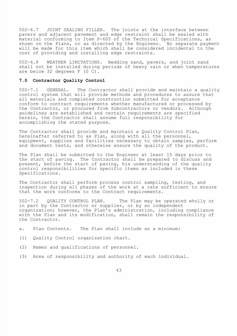
8/10/2019 Us Airfield Manual 2012
http://slidepdf.com/reader/full/us-airfield-manual-2012 47/62
43
502-6.7 JOINT SEALING FILLER. The joints at the interface betweenpavers and adjacent pavement and edge restraint shall be sealed withmaterial conforming to Item P-605 of the Technical Specifications, asshown on the Plans, or as directed by the Engineer. No separate paymentwill be made for this item which shall be considered incidental to thecost of providing and installing edge restraints.
502-6.8 WEATHER LIMITATIONS. Bedding sand, pavers, and joint sandshall not be installed during periods of heavy rain or when temperaturesare below 32 degrees F (0 C).
7.0 Contractor Quality Control
502-7.1 GENERAL. The Contractor shall provide and maintain a qualitycontrol system that will provide methods and procedures to assure thatall materials and completed construction submitted for acceptanceconform to contract requirements whether manufactured or processed bythe Contractor, or procured from Subcontractors or vendors. Althoughguidelines are established and certain requirements are specified
herein, the Contractor shall assume full responsibility foraccomplishing the stated purpose.
The Contractor shall provide and maintain a Quality Control Plan,hereinafter referred to as Plan, along with all the personnel,equipment, supplies and facilities necessary to obtain samples, performand document tests, and otherwise ensure the quality of the product.
The Plan shall be submitted to the Engineer at least 15 days prior tothe start of paving. The Contractor shall be prepared to discuss andpresent, before the start of paving, his understanding of the qualitycontrol responsibilities for specific items as included in theseSpecifications.
The Contractor shall perform process control sampling, testing, andinspection during all phases of the work at a rate sufficient to ensurethat the work conforms to the Contract requirements.
502-7.2 QUALITY CONTROL PLAN. The Plan may be operated wholly orin part by the Contractor or supplier, or by an independentorganization; however, the Plan's administration, including compliancewith the Plan and its modification, shall remain the responsibility ofthe Contractor.
a. Plan Contents. The Plan shall include as a minimum:
(1) Quality Control organization chart.
(2) Names and qualifications of personnel.
(3) Area of responsibility and authority of each individual.

8/10/2019 Us Airfield Manual 2012
http://slidepdf.com/reader/full/us-airfield-manual-2012 48/62
44
(4) A listing of any outside organizations such as testing laboratoriesthat will be employed by the Contractor and a description of theservices they will provide; or indicate if tests will be performed byContractor personnel.
(5) Preparation and maintenance of a Testing Plan which shall contain a
listing of all tests to be performed by the Contractor and the frequencyof testing.
(6) Procedures for ensuring that tests are taken in accordance with theTesting Plan, that they are documented, and that proper correctiveactions are taken when necessary. The testing procedures shall beprescribed by clear and complete instructions and shall assure qualitycontrol testing of materials as required by the Specifications, or asnecessary to maintain the specified quality.
b. Plan Elements. The Plan shall address all elements which affectthe quality of the concrete pavers, including but not necessarilylimited to the following:
(1) Mix Design for Paver Production
(2) Quality of Cementitious Materials and Admixtures
(3) Proportioning
(4) Control of Water-Cement Ratio
(5) Required Strength
(6) Placement of Bedding Sand
(7) Moisture Content and Absorption of Bedding Sand
(8) Thickness, Smoothness, and Grade Control
c. Plan Administration. The Plan shall address management andcoordination of activities of the personnel assigned to this functionand shall incorporate the use of the following types of personnel.
(1) Plan Administrator. The individual administering the Plan must bea full time employee of the Contractor or Paver Installer or aconsultant employed by the Contractor or Paver Installer. In eithercase, the individual employed shall have full authority to institute anyand all actions necessary for the successful operation of the Plan.
(2) Plant Control Technician (PCT). This person shall utilizelaboratory test results and other quality control practices to ensurethe quality of aggregates, cementitious materials, admixtures, and othermix components and adjust and control mix proportioning to meet the mixdesign(s) for paver production. The Plan shall detail the frequency of

8/10/2019 Us Airfield Manual 2012
http://slidepdf.com/reader/full/us-airfield-manual-2012 49/62
45
each type of test, when and how corrective actions are to be taken, andthe means of documentation.
The PCT shall be responsible for periodically inspecting all equipmentutilized in proportioning and mixing to ensure its proper operatingcondition and to ensure that proportioning and mixing is in conformance
with the mix design and other Specification requirements. The Planshall set forth how these duties and responsibilities will beaccomplished and documented. The PCT may be an employee of the pavermanufacturer.
(3) Field Control Technician (FCT). This person shall be responsiblefor periodically inspecting all equipment and processes utilized inplacing to ensure that placing of pavers and bedding and joint sand isin conformance with the Specifications. The Plan shall set forth howthese duties and responsibilities will be accomplished and documented.
The Field Control Technician, who can be the Installer's on-sitesuperintendent, shall also be responsible for the following:
(a) Examine surfaces indicated to receive unit pavers for compliancewith required installation tolerances. Verify that all surfaces toreceive pavers are in proper condition, and that no conditions existwhich may adversely affect progress or quality of work.
(b) Verify that base is dry and ready to support bedding material,pavers, and imposed loads.
(c) Verify base gradients and elevations.
(d) Verify location, type, installation, and elevations of adjacentedge restraints, drainage inlets, grounding lugs, and otherappurtenances in the pavement.
(e) Provide adequate drainage during the entire construction phase bymeans of temporary drains, ditches, or other means to prevent the build-up of standing water.
502-7.3 QUALITY CONTROL TESTING. The Contractor shall perform anyquality control tests necessary to control the production andconstruction processes applicable to these Specifications and as setforth in the approved Quality Control Plan.
a. Paver Production. The testing program for paver manufacture shallinclude, but not necessarily be limited to tests for control of:
(1) Batch proportioning
(2) Aggregate gradation (evidence from quarry tickets will beacceptable).
(3) Aggregate moisture content

8/10/2019 Us Airfield Manual 2012
http://slidepdf.com/reader/full/us-airfield-manual-2012 50/62
46
(4) Water-cement ratio
(5) Density measurements
A minimum of two (2) tests for each shall be made for each productionday. For automated plants with recordation, the Contractor can submit
printed tickets, in lieu of daily testing, provided evidence of recentplant calibration is submitted to the Engineer for approval prior to thestart of production.
b. Bedding and Joint Sand. The Contractor shall control the gradationand moisture content of the bedding and joint sand used forinstallation. In addition, the Contractor shall determine the optimummoisture content for the bedding sand in accordance with ASTM D 1557 andcontrol the moisture content during construction to -2 percent and +3percent of the optimum moisture content. A minimum of one (1) moisturecontent test shall be performed for each lot, as defined in accordancewith paragraph 502-4.1.b. Moisture content testing shall be inaccordance with ASTM C 566.
8.0 Method of Measurement
502-8.1 The quantity of each element of work, installed and accepted,comprising this item, shall be in accordance with the followingmeasurements:
a. Concrete Pavers and Joint Sand. Per square foot (sf) [square meter(sm)], measured in-place, completed and accepted.
b. Bedding Sand. Per ton, measured on approved truck scales,completed and accepted.
c. Edge Restraint. Per linear foot (lf) [linear meter (lm)], measuredin-place, completed and accepted.
d. Sealer. Per square foot (sf) [square meter (sm)], completed andaccepted.
9.0 Basis of Payment
502-9.1 Payment for accepted quantities of concrete pavers shall bemade at the full Contract unit price per square yard. The price shallbe full compensation for manufacturing, furnishing, and placing allmaterials, including pavers, bedding sand, joint sand, edge restraints,and sealer and for all labor, equipment, tools, and incidentalsnecessary to complete this item.
Item P-502-9.1 Concrete Pavers and Joint Sand--per squarefoot (square meter)
Item P-502-9.2 Bedding Sand--per ton (metric ton)

8/10/2019 Us Airfield Manual 2012
http://slidepdf.com/reader/full/us-airfield-manual-2012 51/62
47
Item P-502-9.3 Edge Restraints--per linear foot (linearmeter)
Item P-502-9.4 Sealer--per square foot (square meter)
10.0 Materials and Testing Requirements
ASTM C 33 Specification for Concrete AggregatesASTM C 88 Soundness of Aggregate by use of Sodium
Sulfate or Magnesium SulfateASTM C 131 Method for Resistance to Degradation of Small
Size Course Aggregate by Abrasion and ImpactIn the Los Angeles Machine
ASTM C 136 Method for Sieve Analysis for Fine and CoarseAggregate
ASTM C 140 Method of Sampling and Testing ConcreteMasonry Units
ASTM C 144 Standard Specification for Aggregate forMasonry Mortar
ASTM C 566 Total Moisture Content of Aggregate by DryingASTM C 936 Specification for Solid Interlocking Concrete
Paving UnitsASTM C 979 Pigments for Integrally Colored ConcreteASTM D 1557 Laboratory Compaction Characteristics of Soil
Using Modified Effort.ASTM D 2370 Test for Elongation and Tensile Strength of
Free Films of Paint, Varnish, Lacquer, andRelated Products with a Tensile TestingApparatus
ASTM D 3665 Random Sampling of Paving MaterialsASTM D 7428 Standard Test Method for Resistance of Fine
Aggregate to Degradation by Abrasion in theMicro-Deval Apparatus
CSA-A231.2 Precast Concrete Pavers
END OF ITEM P-502
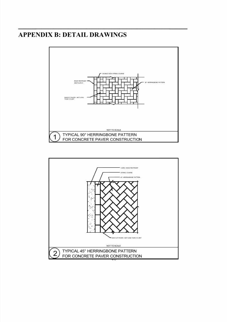
8/10/2019 Us Airfield Manual 2012
http://slidepdf.com/reader/full/us-airfield-manual-2012 52/62
48
DOUBLE ROW STRING COURSE
90° HERRINGBONE PATTERNSEE PLATE 5EDGE RESTRAINT
TYPICAL 90° HERRINGBONE PATTERNFOR CONCRETE PAVER CONSTRUCTION1
NOT TO SCALE
SAWCUT PAVER - NOT LESSTHAN 1/3 UNIT
TYPICAL 45° HERRINGBONE PATTERN
45° HERRINGBONE PATTERN
CURB / EDGE RESTRAINT
STRING COURSE
SAW CUT PAVER - NOT LESS THAN 1/3 UNIT
FOR CONCRETE PAVER CONSTRUCTION2NOT TO SCALE
═════════════════════════════════════════════════════════════════════════════
APPENDIX B: DETAIL DRAWINGS

8/10/2019 Us Airfield Manual 2012
http://slidepdf.com/reader/full/us-airfield-manual-2012 53/62
49
APPROX. 1" TO 1 1/2"(25-40 MM) BEDDING SAND
GEOTEXTILE
CEMENT TREATED BASE (P-304)
SUB-BASE AS REQUIREDCOMPACTED AGGREGATE
SOIL SUBGRADE (P-152)COMPACTED OR STABILIZED
LOADS, SOIL STRENGTH, AND CLIMATE.BASE, SUB-BASE, AND SUBGRADE THICKNESS VARY WITH
AIRFIELD PAVEMENT WITHCEMENT TREATED OR ASPHALT BASE4
NOT TO SCALE
OR ASPHALT BASE (P-401)
(P-209 OR P-154, AS REQUIRED)
TO COVER PAVERSTURN UP AT SIDES
WITH SEALER3 1/8" (80 MM) MIN THICKNESSCONCRETE PAVER (P-502)
NOTE:
V A R I E S
V A R I E S
APPROX. 1" TO 1 1/2"(25-40 mm) BEDDING SAND
BASE AND SUBBASE AS PER PAVEMENT DESIGN
COMPACTED SOIL SUBGRADE (P-152)
CONCRETE PAVER (P-502)3 1/8" (80 mm) MIN THICKNESS
MIN 6" WIDE x 12" DEEP(150 mm x 300 mm) CONCRETE EDGE RESTRAINTWITH TOP 1/4" (7 mm) BELOW TOP OF PAVERS
AND CONTROL JOINTS @ 15' (5 m) O.C. CONCRETE
CONCRETE EDGE RESTRAINT3NOT TO SCALE
EDGE RESTRAINT TO BE DESIGNED TO SUPPORTDESIGN AIRCRAFT LOADING.
GEOTEXTILE ALONG CURB AS REQUIRED
8/10/2019 Us Airfield Manual 2012
http://slidepdf.com/reader/full/us-airfield-manual-2012 54/62
50
TO RECEIVE JOINT FILLER
SAW CUT TO FORM 3/8" (10mm) WIDTH
SAW CUT FACE OF NEW PAVEMENT
3/8" (10mm) NOMINAL
P-401 HOT MIX
CONCRETE BLOCK PAVER
1/2" (13mm) DIA. BACKER ROD
JOINT SEALANT (P-605)
1/2" (13mm) MIN.SEALANT DEPTH
EDGE RESTRAINT JOINT DETAIL6NOT TO SCALE
WOVEN GEOTEXTILE FABRIC STRIP -TURNED UP AT EDGE
CUTTING BLOCKS
2) ADJUST ANGLE LOCATION ± 2" (5cm) TO MINIMIZE
LOCATION AND CUT BACK FOR ANGLE INSTALLATION1) CONSTRUCT P-401 OVERLAY APPROX. 2' (60cm) PAST ANGLE
NOTES:
FINAL 2 LIFTS OF P-401 HOT MIX
SEE DETAIL - PLATE 6
3" x 3" x 3/16" (7.5cm x 7.5cm x 5mm) GALV. STEEL ANGLE
1/2" (13mm) DIA x 12" (30cm) LONG GALV. STEEL SPIKE - 24" (60cm) O.C.
BEDDING SAND
CONCRETE PAVER BLOCKS (P-502)
INLAY AND ANGLE EDGE RESTRAINT DETAIL5NOT TO SCALE
PRE-DRILLED @ 24" (60cm) O.C.
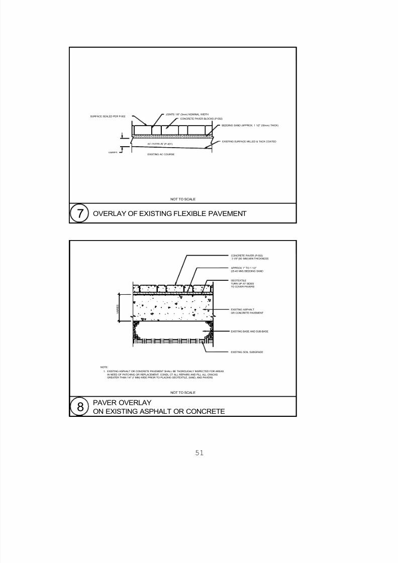
8/10/2019 Us Airfield Manual 2012
http://slidepdf.com/reader/full/us-airfield-manual-2012 55/62
51
JOINTS 1/8" (3mm) NOMINAL WIDTHSURFACE SEALED PER P-502
CONCRETE PAVER BLOCKS (P-502)
BEDDING SAND (APPROX. 1 1/2" (30mm) THICK)
EXISTING SURFACE MILLED & TACK COATED
EXISTING AC COURSE
AC OVERLAY (P-401)
OVERLAY OF EXISTING FLEXIBLE PAVEMENT7NOT TO SCALE
VARIES
1.
NOTE:
TURN UP AT SIDESTO COVER PAVERS
V A R I E S
CONCRETE PAVER (P-502)3 1/8" (80 MM) MIN THICKNESS
APPROX. 1" TO 1 1/2"(25-40 MM) BEDDING SAND
GEOTEXTILE
EXISTING SOIL SUBGRADE
EXISTING BASE AND SUB-BASE
OR CONCRETE PAVEMENTEXISTING ASPHALT
GREATER THAN 1/4" (7 MM) WIDE PRIOR TO PLACING GEOTEXTILE, SAND, AND PAVERS.IN NEED OF PATCHING OR REPLACEMENT. CONDU CT ALL REPAIRS AND FILL ALL CRACKSEXISTING ASPHALT OR CONCRETE PAVEMENT SHALL BE THOROUGHLY INSPECTED FOR AREAS
PAVER OVERLAYON EXISTING ASPHALT OR CONCRETE8
NOT TO SCALE
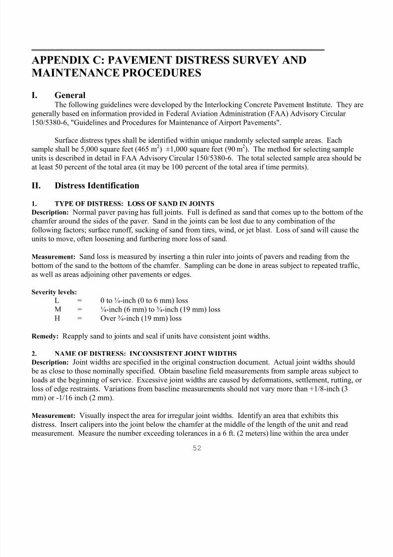
8/10/2019 Us Airfield Manual 2012
http://slidepdf.com/reader/full/us-airfield-manual-2012 56/62
52
═════════════════════════════════════════════════════════════════════════════
APPENDIX C: PAVEMENT DISTRESS SURVEY ANDMAINTENANCE PROCEDURES
I. General The following guidelines were developed by the Interlocking Concrete Pavement Institute. They aregenerally based on information provided in Federal Aviation Administration (FAA) Advisory Circular150/5380-6, "Guidelines and Procedures for Maintenance of Airport Pavements".
Surface distress types shall be identified within unique randomly selected sample areas. Eachsample shall be 5,000 square feet (465 m 2) ±1,000 square feet (90 m 2). The method for selecting sampleunits is described in detail in FAA Advisory Circular 150/5380-6. The total selected sample area should beat least 50 percent of the total area (it may be 100 percent of the total area if time permits).
II. Distress Identification
1. TYPE OF DISTRESS: LOSS OF SAND IN JOINTS Description: Normal paver paving has full joints. Full is defined as sand that comes up to the bottom of thechamfer around the sides of the paver. Sand in the joints can be lost due to any combination of thefollowing factors; surface runoff, sucking of sand from tires, wind, or jet blast. Loss of sand will cause theunits to move, often loosening and furthering more loss of sand.
Measurement: Sand loss is measured by inserting a thin ruler into joints of pavers and reading from the bottom of the sand to the bottom of the chamfer. Sampling can be done in areas subject to repeated traffic,as well as areas adjoining other pavements or edges.
Severity levels: L = 0 to ¼-inch (0 to 6 mm) lossM = ¼-inch (6 mm) to ¾-inch (19 mm) lossH = Over ¾-inch (19 mm) loss
Remedy: Reapply sand to joints and seal if units have consistent joint widths.
2. NAME OF DISTRESS: INCONSISTENT JOINT WIDTHSDescription: Joint widths are specified in the original construction document. Actual joint widths should
be as close to those nominally specified. Obtain baseline field measurements from sample areas subject toloads at the beginning of service. Excessive joint widths are caused by deformations, settlement, rutting, or
loss of edge restraints. Variations from baseline measurements should not vary more than +1/8-inch (3mm) or -1/16 inch (2 mm).
Measurement: Visually inspect the area for irregular joint widths. Identify an area that exhibits thisdistress. Insert calipers into the joint below the chamfer at the middle of the length of the unit and readmeasurement. Measure the number exceeding tolerances in a 6 ft. (2 meters) line within the area under
8/10/2019 Us Airfield Manual 2012
http://slidepdf.com/reader/full/us-airfield-manual-2012 57/62
53
inspection. Joint widths that are too narrow or too wide can be precursors to edge spalling or joint sealdamage.
Severity levels: L = Only a few joints out of dimensional tolerances, movement of only scattered units.
M = Joint widths are out of tolerance, concentrated in one (1) sample unit.H = Joint widths are out of tolerance in several sample units.
Remedy: Once the cause is identified and solved, the units can be cleaned and replaced with joints tospecification, vibrated and sealed.
3. NAME OF DISTRESS: CORNER OR EDGE SPALLINGDescription: A corner or edge spall intersects the joint at an angle. It does not extend vertically through the
paving unit. It can be caused by loss of sand, loads and/or settlement that cause the top edges of adjacentunits to creep together and break.
Measurement: If one or more than one severity level occurs, the higher level should be recorded for thearea.
Severity levels: L = Spall has little or no loose particles. Width of spalling is less than 1/8-inch (3 mm)
wide.M = Moderately spalled with some loose, in-place particles. Spalling is 1/8-inch (3 mm)
to 1-inch (25 mm) wide.H = Spall is greater than 1-inch (25 mm) wide with loose, in-place, or missing particles.
Tire damage or FOD is a risk.
Remedy: For M & H severity levels, remove damage pavers, replace, and seal.
4. NAME OF DISTRESS: CRACKED PAVERSDescription: Longitudinal, transverse, or diagonal cracks are caused by loads and run vertically through theunit. Cracks can be caused by defective pavers that break under loads. The cracks divide the unit into twoor more pieces. Cracks have little or no openings. The units may perform for a time in a cracked state, butshould be replaced as the cracking may lead to corner or edge spalling. Units generally do not crack underloss of subgrade support.
Measurement: Identify cracked pavers at each severity level.
Severity Level: L = Units have cracks that are not spalled or chipped.M = Units have cracks that are lightly spalled with loose particles.H = Units have cracks that are severely spalled with loose or missing particles. FOD is a
high risk.
Remedy: For M and H severity, remove cracked pavers, replace, and seal.

8/10/2019 Us Airfield Manual 2012
http://slidepdf.com/reader/full/us-airfield-manual-2012 58/62
8/10/2019 Us Airfield Manual 2012
http://slidepdf.com/reader/full/us-airfield-manual-2012 59/62
55
Severity levels: L = Depression can be observed only by stained areas or brief ponding after a rainstorm.
Taxiways and aprons: Depression ranges from ½-inch (13 mm) to 1-inch (25 mm).M = Depression are visible without ponding. Taxiways and aprons: depression ranges
from 1-inch (25 mm) to 2 inches (50 mm).H = Depression can be readily observed and severely effects riding quality. Taxiwaysand apron: depression is greater than 2 inches (50 mm).
Remedy: Remove the units, locate and repair the cause of the settlement, reinstate sand, units, and seal.
8. NAME OF DISTRESS: SETTLEMENT OR FAULTINGDescription: This is defined as a clear difference in elevation between areas of pavers caused by movementof underlying layers or differential consolidation of the sand or base.
Measurement: The surface area of the affected pavement is recorded in square feet (square meter) and
differentiated by severity level.Severity levels:
L = Taxiways: less than ¼-inch (6 mm); Apron: _-inch (3 mm) to ½-inch (13 mm)difference in elevation.
M = Taxiways: ¼-inch (6 mm) to ½-inch (13 mm); Aprons: ½-inch (13 mm) to 1-inch(25 mm).
H = Taxiways: greater than ½-inch (13 mm); Apron: greater than 1-inch (25 mm).
Remedy: Remove the units, locate and repair source of settlement; reinstate units at correct elevations.
9. NAME OF DISTRESS: POLISHED AGGREGATESDescription: Some aggregates polish quickly under traffic or polish naturally from weather.
Measurement: Friction testing in accordance with FAA Advisory Circular 150/5320-12, "Measurement,Construction, and Maintenance of Skid-Resistant Airport Pavement Surfaces".
Severity level: Use skid resistance standards.
Remedy: Sand blast to regain roughness. Wash thoroughly, dry and seal. If units polish quickly, replacewith units with harder sand/aggregate composition.
10. NAME OF DISTRESS: PUMPING AND WATER BLEEDINGDescription: Pumping is the ejection of material by water through joints caused by deflection of the unitsunder passing loads. Sand is ejected through the joint resulting in surface staining. Material on the
pavement close to joints are evidence of pumping. Pumping indicates poor joint sealing usuallyaccompanied by base or soil deformation.
Measurement: Identify area that is pumping.

8/10/2019 Us Airfield Manual 2012
http://slidepdf.com/reader/full/us-airfield-manual-2012 60/62
56
Severity levels: No degrees of severity are defined. It is sufficient to indicate that pumping exists.
Remedy: Remove units, repair base, install drainage as needed, replace pavers and seal.
11. NAME OF DISTRESS: RUTTING
Description: Rutting is a surface depression in a wheel path. In many cases, ruts are only noticeable onlyafter a rainfall when the wheel paths are filled with water. Rutting is caused by consolidation from trafficloads that can permanently deform the sand, base, or soil subgrade. Rutting is a structural deficiency that isnormally indicative of a pavement structured that is underdesigned for the intended loading condition.
Measurement: The area of rutting is documented with the mean depth of the rut. Depth is measured at thedeepest point (center) of the rut, along the length of the rut.
Severity level: L = ¼-inch (6 mm) to ½-inch (13 mm)M = ½-inch (13 mm) to 1-inch (25 mm)
H = greater than 1-inch (25 mm)Remedy: For M & H severity, remove units and sand, repair base, install pavement materials to desiredelevation. Reinstate sand, pavers, vibrate with sand, clean, and seal. Full depth repair of base and subbaselayers may also be required to provide adequate structural support.
12. NAME OF DISTRESS: HORIZONTAL CREEPINGDescription: Creeping of units is caused by repeated braking, accelerating, or turning in an area. The jointlines will bend following the direction of the moving wheel(s). Creeping will eventually open paver joints,damage joint sealing, and accelerate deterioration.
Measurement: At the opening of the areas, two points should be marked on the pavement across areassubject to turning, braking, or accelerating. The points should align with the joints of the pavers. These are
the reference lines. Deviations from these lines should be checked to monitor creeping.
Severity levels: L = ¼-inch (6 mm) or less deviation from reference line.M = ¼-inch (6 mm) to ½-inch (13 mm) deviation from reference line.H = Greater than ½-inch (13 mm) deviation from reference line.
Remedy: For H severity, remove units back to area with stable, consistent joints. Open joints slightly in pavers adjacent to opening. Reinstall pavers in opening with consistent joints, matching those widths tothose in the areas adjacent to the opening. Spread sand, vibrate, clean and seal.
13. NAME OF DISTRESS: SWELLDescription: Swell is an upward bulge in the pavement's surface. A swell is usually caused by frost actionin the subgrade or swelling soil; however, swelling can be caused by other factors. Therefore, the cause ofthe swelling should be investigated.

8/10/2019 Us Airfield Manual 2012
http://slidepdf.com/reader/full/us-airfield-manual-2012 61/62
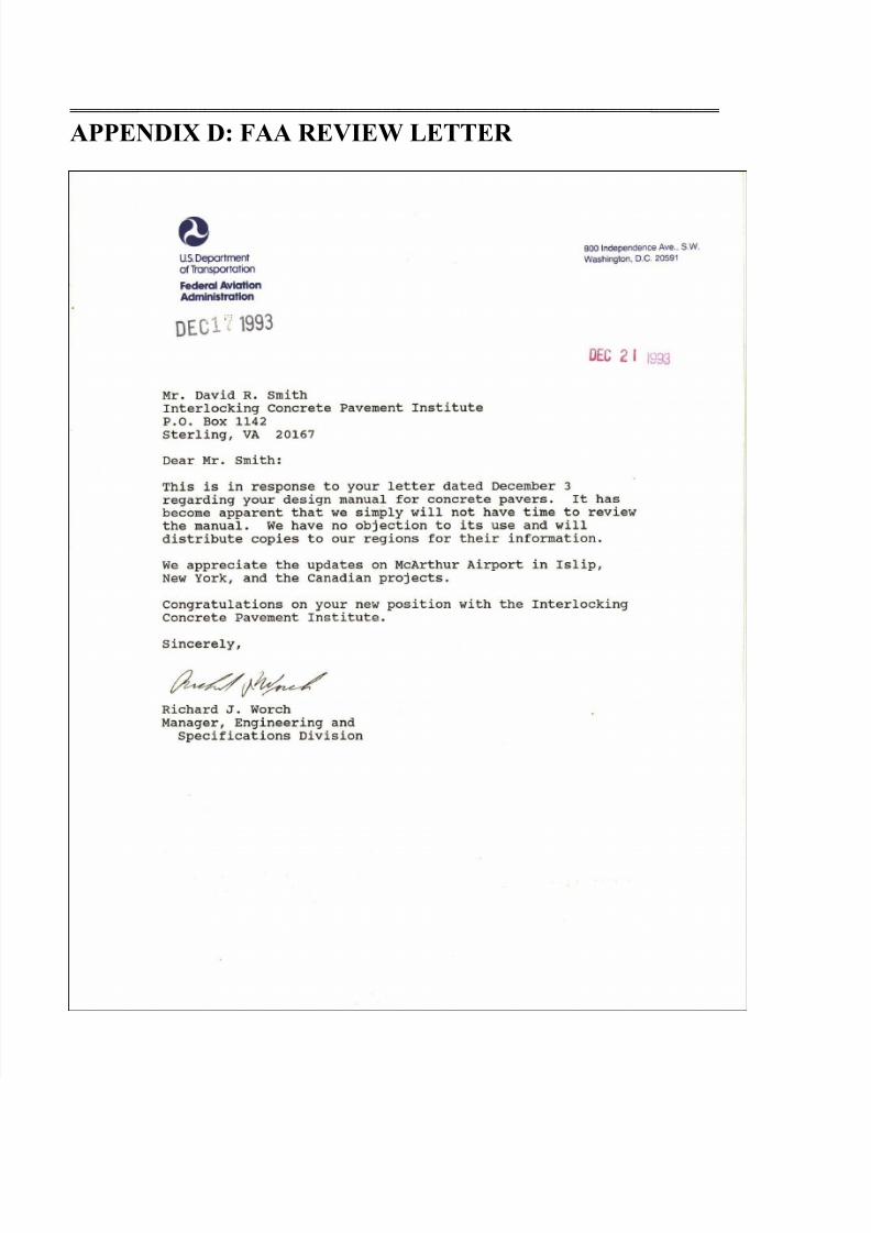
8/10/2019 Us Airfield Manual 2012
http://slidepdf.com/reader/full/us-airfield-manual-2012 62/62
═════════════════════════════════════════════════════════════════════════════
APPENDIX D: FAA REVIEW LETTER