Ural (Урал) Russian Motorcycle III-4...Ural (Урал)Russian Motorcycle Generators and...
18
Ural ( Урал) Russian Motorcycle Generators and Alternators Part III - 4: 14.3771 and Nippon - Denso Alternators Ernie Franke [email protected] 02 / 2018
Transcript of Ural (Урал) Russian Motorcycle III-4...Ural (Урал)Russian Motorcycle Generators and...

Ural (Урал)Russian Motorcycle
Generators and AlternatorsPart III-4: 14.3771 and
Nippon-Denso Alternators
Ernie Franke
02 / 2018

Types of Generators/Alternators for Ural (Урал) and Dnepr (Днепр)
Generator/Alternator
Type Vintage NominalVoltage
Current NominalPower
Motorcycles
Ural(IMZ) Dnepr (KMZ)
Г-11(G-11)
(P/N: 72181)
DCGenerator
1941-1951
6-Volt(7-Volt) 7-Amp 45-Watts M-72 Not Used
Г-11A(G-11A)
(P/N: 72181-A)
DC Generator
1952-1957
6-Volt(7-Volt)
7-Amp 45-Watts M-72, M-72M , M-61
M-72, M-72N,early K-750
Г-414(G-414)
(P/N: 750181)
DC Generator
1957-1974
6-Volt(7-Volt)
10-Amp 65-Watts M-62, M-63, M-66
K-650, later K-750, K-750M, MB-750,
MB-750M, MT-8, MT-9, MT-12
Г-424(G-424)
(P/N: 3701000)
Alternator(Built-in
Rectifier)
1974-1998 12-Volt
(14-Volt)14-Amp 150-Watts
M-67, M-67.36, IMZ 8.103 Series
MB-650, MB-650M,MT-10, MT-10.36,
MT-11, MT-16
Hitachi(Limited
Appearance)
Starter / Generator
1998-1998.5 12-Volt
(14-Volt)18-Amp 300-Watts
IMZ 8.103 and8.107
“650” SeriesNot Used
14.3771(RPOC)
(P/N: 14.3771-010)
Alternator(Built-in
Rectifier &Regulator)
1998.5-2004
12-Volt(14-Volt)
35-Amp 500-WattsIMZ 8.103, 8.103X,
8.123, 8.123X“650 & 750” Series
Not Used
NipponDenso
(P/N: IMZ-8.1037-18092)
Alternator(Built-in
Rectifier &Regulator)
2004-present 12-Volt
(14-Volt)55-Amp 770-Watts
IMZ 8.103, 8.103X,8.123, 8.123X“750” Series
Not Used
Notes:1. Nomenclature: The Cyrillic letter “Г” transliterates (Russian-to-Latin) to “G” or “L” or “T.” Thus we
see Г-414 or G-414 or L-414 or T-414, all the same part.2. Cannot use Г-424 Alternator with discharged battery or without battery.3. MB-750 = MW-750, MB-750M = MB-750M4. The frame (case) of the Г-11/Г-11A generator is positive (positive-ground).5. Γ-414 Generator: P/N: 750181 6-Volt (negative ground), whereas P/N: 750181-A (positive-ground) for
fitting Г-11A’s into early K-750’s.
2

Ural (Урал) - Dnepr (Днепр)Generator/Alternator Time-Line
time
195019801960 197019651955 1975
2010200520001990 19951985
(M-72 thru M-66, MT-9) 6-Volts
Г-414(MT-8)
Г-414(M-62)
Г-11A(M-72N)
Г-414(later K-750)
Г-424(M-67.36)
Г-11A
(KMZ M-72)
Г-424(MT-11)
Г-11A
(M-72)
Г-414(M-63,
K-750M,MB-750)
Г-414(M-66,MT-9)
Г-424(M-67, MT-10, MT-
12, MB-750)
Г-424(IMZ 8.103,
8.107,“650”)
14.3771(IMZ 8.103,
8.107,“650 & 750”)
Г-424(MT-16)
12-Volts (M-67, MT-10 and beyond)
1974
Alternators have progressed in output voltage and power, From the Г-11 (G-11) generator of 6-Volts/45-Watts in 1941,
the Г-11A in 1952, the Г-414 6V/65 W in 1957, the Г-424 of 12V/150W in 1974, the 14.3771 of 12V/500W in 1998.5,
to the present-day Nippon-Denso alternator of 12-V/770W.
DC Generator Alternator (AC Generator with Built-In Rectifier)
1974
Г-414 Generator Г-424 Alternator
14.3771Alternator
Nippon-Denso
AlternatorГ-11A
Generator
Г-11Generator
1957 1998.5 20041951
Г-424(M-T-10.36)Г-424
(MB-650)Г-11A(early K-750)
Nippon-Denso(IMZ 8.103,
8.123,“750”)
3
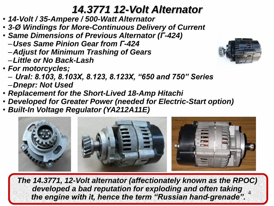
14.3771 12-Volt Alternator• 14-Volt / 35-Ampere / 500-Watt Alternator• 3-Ø Windings for More-Continuous Delivery of Current• Same Dimensions of Previous Alternator (Γ-424)–Uses Same Pinion Gear from Γ-424–Adjust for Minimum Trashing of Gears–Little or No Back-Lash
• For motorcycles;– Ural: 8.103, 8.103X, 8.123, 8.123X, “650 and 750” Series–Dnepr: Not Used
• Replacement for the Short-Lived 18-Amp Hitachi• Developed for Greater Power (needed for Electric-Start option)• Built-In Voltage Regulator (YA212A11E)
The 14.3771, 12-Volt alternator (affectionately known as the RPOC) developed a bad reputation for exploding and often taking the engine with it, hence the term “Russian hand-grenade”.
4
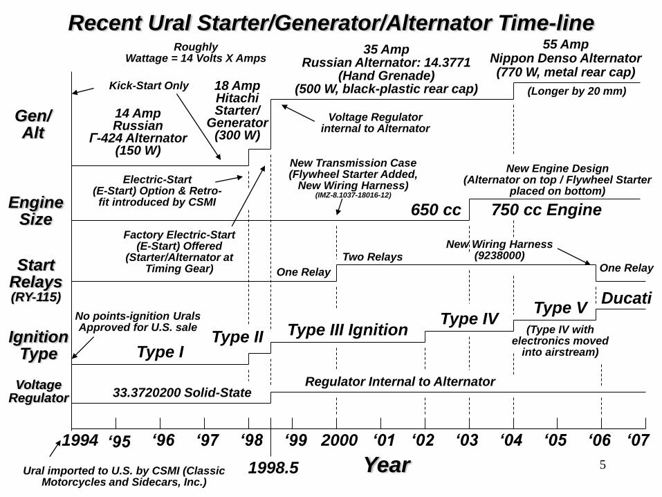
Recent Ural Starter/Generator/Alternator Time-line
EngineSize
Year
‘96 ‘07‘04‘02‘98
1998.5
2000
650 cc 750 cc Engine
New Engine Design (Alternator on top / Flywheel Starter
placed on bottom)
Gen/Alt
IgnitionType
1994
Ural imported to U.S. by CSMI (Classic Motorcycles and Sidecars, Inc.)
55 Amp Nippon Denso Alternator(770 W, metal rear cap)
Type IType II Type III Ignition
Type IVType V
(Type IV with electronics moved
into airstream)
Ducati
14 AmpRussian
Г-424 Alternator(150 W)
18 AmpHitachiStarter/
Generator(300 W)
35 AmpRussian Alternator: 14.3771
(Hand Grenade)(500 W, black-plastic rear cap) (Longer by 20 mm)
RoughlyWattage = 14 Volts X Amps
Factory Electric-Start (E-Start) Offered
(Starter/Alternator atTiming Gear)
Voltage Regulator internal to Alternator
Electric-Start (E-Start) Option & Retro-fit introduced by CSMI
StartRelays(RY-115)
One Relay One RelayTwo Relays
No points-ignition UralsApproved for U.S. sale
‘03 ‘05
Kick-Start Only
VoltageRegulator
Regulator Internal to Alternator33.3720200 Solid-State
New Transmission Case(Flywheel Starter Added,
New Wiring Harness)(IMZ-8.1037-18016-12)
New Wiring Harness (9238000)
‘01 ‘06‘99‘97‘95
5

14.3771 12-Volt Alternator
6
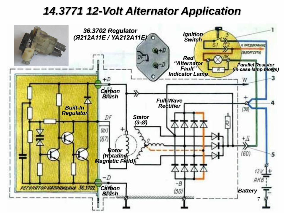
14.3771 12-Volt Alternator Application
36.3702 Regulator(Я212А11Е / YA212A11E)
Built-InRegulator
Rotor(Rotating
Magnetic Field)
Red“Alternator
Fault”Indicator Lamp
IgnitionSwitch
Full-WaveRectifier
Stator(3-Ø)
Parallel Resistor(in case lamp blows)
Carbon Brush
Carbon Brush
Battery
7

Starter Interlock Circuit• Starter circuit has an interlock relay (electric start relay #1 on diagram)
tied to the alternator warning light, designed such that the starter will not run when the warning light is off.
• Intended to prevent starter engagement when/if the engine is already running
• Starter relay gets it's ground through the field winding of the alternator, so does the alternator fault lamp. If the alternator field is OK, then the alternator fault lamp will light and the starter relay will pull in when you push the electric start button. When the engine is running and the alternator is producing power, then there will be +12 volts at the field winding terminal & the alternator fault light will turn off and the start relay will lose the ground connection. The reason for this, is so that it is not possible to engage the electric starter when the engine is running. Sounds good so far, but if the field winding goes open circuit, or the alternator is removed, there is no ground path for the start relay and therefore the electric start and red fault lamp will not work.
• Here's what you do. Ground the wire that went to the field winding tab on the alternator. Now the red alternator light will come on and you can use the electric start again if you want to. Once you replace the alternator with a good one, everything should be back to normal again. Note! The above explanation is true only on the 2002 models.
8

.
.
Connector Pin
Male Female
Ural 650/750 Starter/Alternator Circuit (2002-2003)(IMZ-8.103717001-13, 2002 & 2003 Owners Manuals)
Terminal
85 86 30 87 85 86 30 87
Pos +
Neg -
Green(Neutral)
Red(Alternator
Fault)
Neutral Switch
RY-115Electric Start
Relay #1(Normally Open)
RY-115Electric Start
Relay #2(Normally Open)
Starter Motor
12 VoltBattery
Momentary“Start” Button
Rocker-Arm“Run / Kill”
Switch
Right Handlebar
Headlight Cavity
6 5 1 2 3
Ignition Key
blackwhite
white
largewhite
red
Fuse Block
4
3
1
2
grn / red
yel / red
red
pnk/ blkIgnitionModule
+ -
In-Line Fuse #1
red
+ FaultTerminal(spade)
blue
Starter Solenoid
largeblack
green
Ignition
Switch
green
Notes:1. In-Line Fuse #1 (15A) for Turn
Signal and Neutral Indicator Lamp.2. Fuse Block #4 Fuse (5A) for
Ignition & Electric Start Relays.
8586
30
87
ChassisGround
“Run”“Kill”
(+12V. When Ignition Switch on “Run”)
(0V.: Engine not running,+12V.: Engine running and
Alternator working.”)
(+12V. in “Run” position)
“Start”
top
bottom
14.377135 Amp RussianHand Grenade
Brakes
Headlites
Run Lites
+ Main Output(ring)
red
gray
(back-side)(face-side)
red
9-pin Connector
9
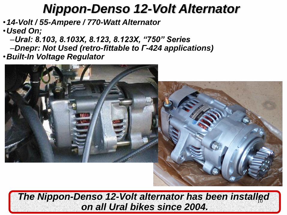
Nippon-Denso 12-Volt Alternator•14-Volt / 55-Ampere / 770-Watt Alternator•Used On;–Ural: 8.103, 8.103X, 8.123, 8.123X, “750” Series–Dnepr: Not Used (retro-fittable to Г-424 applications)
•Built-In Voltage Regulator
The Nippon-Denso 12-Volt alternator has been installed on all Ural bikes since 2004.
10
.
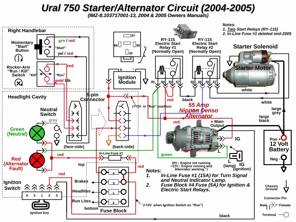
Ural 750 Starter/Alternator Circuit (2004-2005)(IMZ-8.103717001-13, 2004 & 2005 Owners Manuals)
Connector Pin
Male Female
Terminal
85 86 30 87 85 86 30 87
Pos +
Neg -Red(Alternator
Fault)
RY-115Electric Start
Relay #1(Normally Open)
RY-115Electric Start
Relay #2(Normally Open)
Starter Motor
12 VoltBattery
Headlight Cavity
6 5 1 2 3
Ignition Key
blackwhite
white
largegrey
red
Fuse Block
4
3
1
2
red
red
blue
Starter Solenoid
largeblack
black
Ignition
Switch
redNotes:1. In-Line Fuse #1 (15A) for Turn Signal
and Neutral Indicator Lamp.2. Fuse Block #4 Fuse (5A) for Ignition &
Electric Start Relays.ChassisGround
(+12V. when Ignition Switch on “Run”)
(0V.: Engine not running+12V.: Engine running and
Alternator working.”)
bottom
Notes:1. Two Start Relays (RY-115)2. In-Line Fuse #1 deleted mid-2005
55 Amp Nippon Denso
Alternator+ Main Output
IG(ignition)
L(lamp)
L
IG
green
Brakes
Headlites
Run Lites
(+12V. in “Run” position)
Green(Neutral)
.
Neutral Switch
Right Handlebar
grn / red
yel / red
red
pnk/ blkIgnitionModule
+ -
In-Line Fuse #1
8586
30
87
“Run”“Kill”
“Start”
top
red
gray
(back-side)(face-side)
9-pin Connector
.
Rocker-Arm“Run / Kill”
Switch
Momentary“Start” Button
11

.
Ural 750 Starter Circuit (2006-2007)(Electrex, Inc. Rev. E, 2006 GPTT, 2006 & 2007 Owners Manuals)
Connector Pin
Male Female
Terminal
85 86 30 87
Pos +
Neg -
Green(Neutral)
Red(Alternator
Fault)
RY-115Electric Start Relay
(Normally Open)
Starter Motor
55 AmpNippon Denso
Alternator
12 VoltBattery
Right Handlebar
Headlight Cavity
5 6 1 2 3
Ignition Key
16 wht
16 red
8 red
Fuse Block
15A
5A
15A
5A
grn/red
yel/red
red
pnk/blkDucati
Ignition
Module
+ -
18 pnk/blk
+ Main Output
18 blu/wht
Starter Solenoid
12 red
IgnitionSwitch
10-pin Connector
Note: # in front of wire color is AWG wire size.
18 blu
8586
30
87
ChassisGround
GFED
Neutral Switch
12 red
18 pnk
18 blk/red
14 blu
8 blk
14 blu
18 brn/red
18 brn/red
18 brn/red
18 blk/red
18 pnk/blk
Momentary“Start” Button
Rocker-Arm“Run / Kill”
Switch“Kill”
(+12V. in ”Run” position)
“Start”
“Run”
IG(ignition)
L(lamp)
L
IG
Notes:1. Single Start Relay (RY-115)2. ND Alternator added 20043. In-Line Fuse #1 Deleted mid-2005
12

Good Websites for Upgrading to the Nippon-Denso Alternator
•From Г-424 Alternator–http://www.crawfordsales.info/ural/articles/upgradingToDenso/
•From 14.3771–http://www.dwightrahl.com/NipponDenso3.html–http://myural.com/alternator.htm
13

How to Wire the Nippon-Denso Alternator Retro-fitable to the 14.377 Alternator
( compliments of Crawford Sales)
• Connect the Two Ring-Type Eyelet Connectors to the Top-Post Connector
• Connect the Existing Green Spade-Type Connector to the Left-Side (horizontal) of the Two Terminals on the Back of the Alternator
• Now, you've got that new red pigtail to hook up. • Look for the Ignition Power Wire coming out of the Top of the Front
Ignition Cover• Follow It Back a Few inches to the Black Plastic Connector• Pull It Apart• Plug in the Short, Female Connector to the Wire coming out of the
Ignition Cover• Plug the Male Connector into the Main Wiring Harness Side• Run the Long Red Wire• Attach it to the Right-Side (vertical) Connector on the Back of the
Alternator, Next to that Green Wire
Crawford Sales noticed that step 4 of the supplied instructions for the Nippon-Denso alternator was perhaps not as clear
as they'd like. They hope this revised procedure helps.14
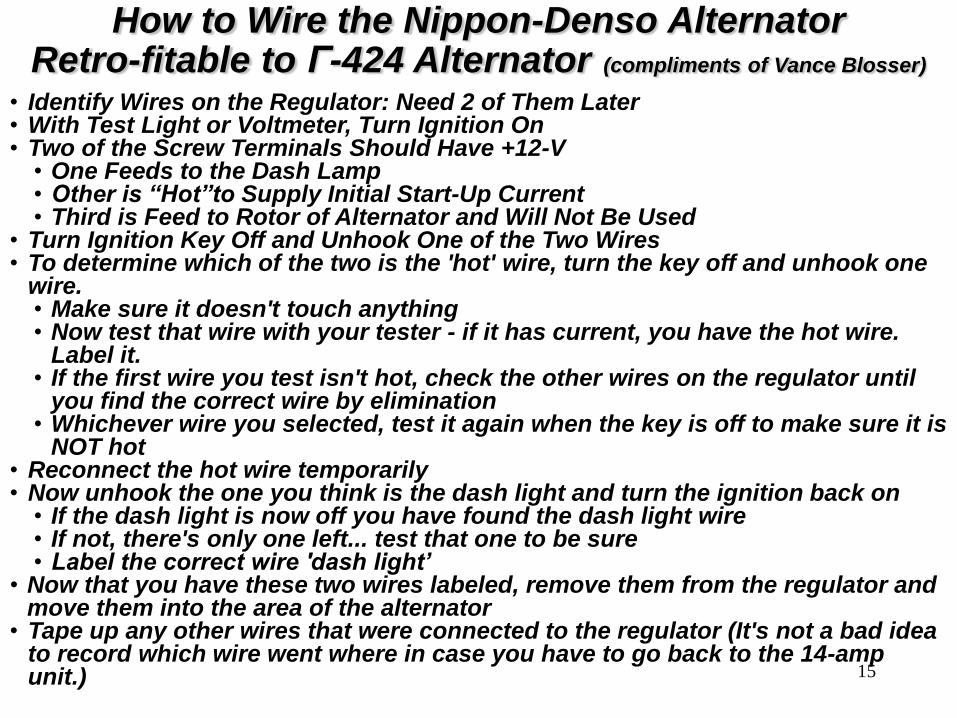
How to Wire the Nippon-Denso Alternator Retro-fitable to Г-424 Alternator (compliments of Vance Blosser)
• Identify Wires on the Regulator: Need 2 of Them Later• With Test Light or Voltmeter, Turn Ignition On• Two of the Screw Terminals Should Have +12-V
• One Feeds to the Dash Lamp• Other is “Hot”to Supply Initial Start-Up Current• Third is Feed to Rotor of Alternator and Will Not Be Used
• Turn Ignition Key Off and Unhook One of the Two Wires• To determine which of the two is the 'hot' wire, turn the key off and unhook one
wire.• Make sure it doesn't touch anything• Now test that wire with your tester - if it has current, you have the hot wire.
Label it.• If the first wire you test isn't hot, check the other wires on the regulator until
you find the correct wire by elimination• Whichever wire you selected, test it again when the key is off to make sure it is
NOT hot• Reconnect the hot wire temporarily• Now unhook the one you think is the dash light and turn the ignition back on
• If the dash light is now off you have found the dash light wire• If not, there's only one left... test that one to be sure• Label the correct wire 'dash light’
• Now that you have these two wires labeled, remove them from the regulator and move them into the area of the alternator
• Tape up any other wires that were connected to the regulator (It's not a bad idea to record which wire went where in case you have to go back to the 14-amp unit.) 15
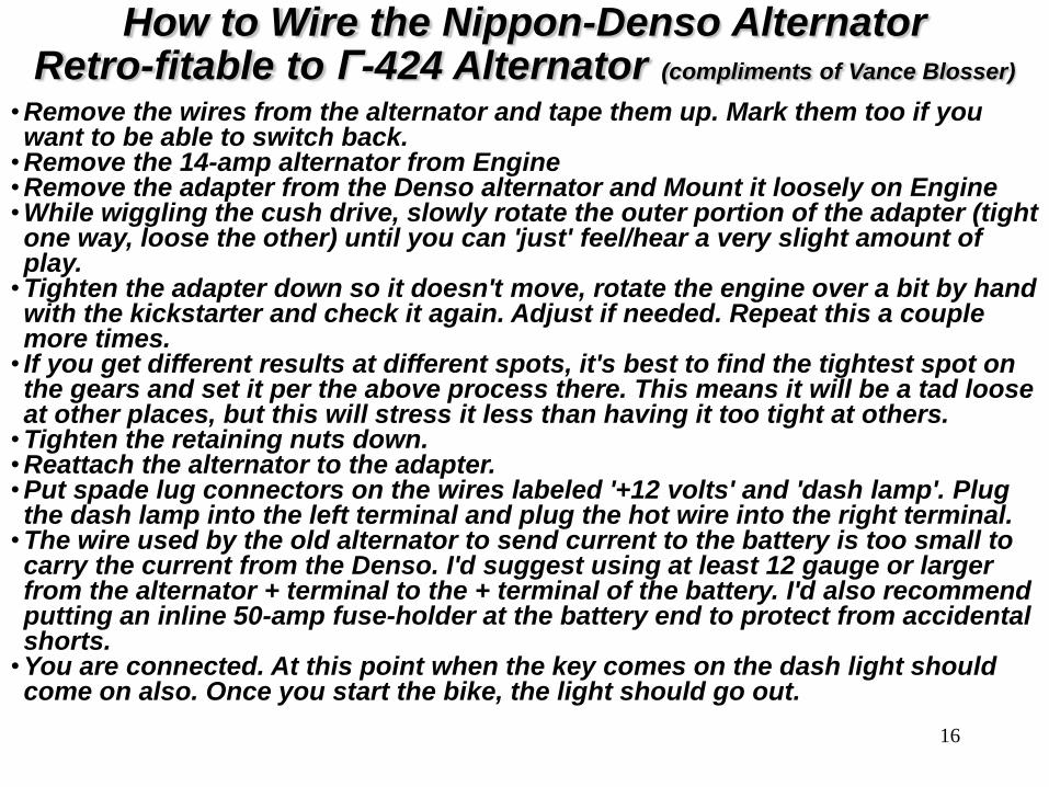
How to Wire the Nippon-Denso Alternator Retro-fitable to Г-424 Alternator (compliments of Vance Blosser)
•Remove the wires from the alternator and tape them up. Mark them too if you want to be able to switch back.
•Remove the 14-amp alternator from Engine•Remove the adapter from the Denso alternator and Mount it loosely on Engine•While wiggling the cush drive, slowly rotate the outer portion of the adapter (tight one way, loose the other) until you can 'just' feel/hear a very slight amount of play.
•Tighten the adapter down so it doesn't move, rotate the engine over a bit by hand with the kickstarter and check it again. Adjust if needed. Repeat this a couple more times.
• If you get different results at different spots, it's best to find the tightest spot on the gears and set it per the above process there. This means it will be a tad loose at other places, but this will stress it less than having it too tight at others.
•Tighten the retaining nuts down. •Reattach the alternator to the adapter. •Put spade lug connectors on the wires labeled '+12 volts' and 'dash lamp'. Plug the dash lamp into the left terminal and plug the hot wire into the right terminal.
•The wire used by the old alternator to send current to the battery is too small to carry the current from the Denso. I'd suggest using at least 12 gauge or larger from the alternator + terminal to the + terminal of the battery. I'd also recommend putting an inline 50-amp fuse-holder at the battery end to protect from accidental shorts.
•You are connected. At this point when the key comes on the dash light should come on also. Once you start the bike, the light should go out.
16

Parts Breakdown of Nippon-Denso Alternator (01/11)
17

Newest Style Alternator• Seal in the Front of the Adapter
• Complete with Herzog Gear
Newest Style Alternator
List Price: Cost - $541
(www.russianiron.com)
18