Uptimax Ni-Cd battery Technical manual
28
Uptimax Ni-Cd battery Technical manual June 2010
Transcript of Uptimax Ni-Cd battery Technical manual
Uptimax Ni-Cd batteryTechnical manual
June 2010

1. Introduction 3
2. Battery applications 4
3. Principles of the oxygen recombination cycle 5
4. Construction features of the Uptimax battery 7 4.1 Plate assembly 7 4.2 Separation 8 4.3 Electrolyte 8 4.4 Terminal pillars 8 4.5 Venting system 8 4.6 Cell container 8
5. Benefits of the Uptimax battery 9
6. Operating features 10 6.1 Capacity 10 6.2 Cell voltage 10 6.3 Internal resistance 10 6.4 Effect of temperature on performance 11 6.5 Short-circuit values 11 6.6 Open circuit loss 12 6.7 Cycling 12 6.8 Water consumption 13 6.9 Gas evolution 13
7. Battery charging 14 7.1 Charging methods 14 7.2 Charge acceptance 15 7.3 Charge efficiency 16 7.4 Temperature effects 16
8. Special operating factors 17 8.1 Electrical abuse 17 8.2 Mechanical abuse 17
9. Battery sizing principles in stationary applications 18 9.1 The voltage window 18 9.2 Discharge profile 18 9.3 Temperature 18 9.4 State of charge or recharge time 19 9.5 Ageing 19 9.6 Floating effect 19
10. Installation and operating instructions 20 10.1 Receiving the shipment 20 10.2 Storage 20 10.3 Installation 20 10.4 Commissioning 21 10.5 Charging in service 22 10.6 Periodic maintenance 22
11. Maintenance of Uptimax batteries in service 23
12. Disposal and recycling 24
Contents
The nickel-cadmium battery is the most reliable battery system available in the market today. Its unique features enable it to be used in applications and environments untenable for other widely available battery systems. With the advent of the valve- regulated lead acid battery a new concept was available to the customer, a battery that did not require water replenishment. However, this was obtained at the cost of reliability. To give the customer a highly reliable battery of zero or ultra-low maintenance Saft has developed the Uptimax low maintenance pocket plate battery.
This publication details the design and operating characteristics of the Saft Nife brand Uptimax battery to enable a successful battery system to be achieved. A battery which in normal application requires only one topping-up during its entire service life but has all the well-proven advantages of the nickel-cadmium pocket plate battery.
1. Introduction3
UPS Process control Emergency systems Security systems Offshore oil and gas Switchgear
Uptimax batteries are designed to supply the ideal low maintenance power backup solution for installations that demand maximum reliability and optimum TCO (total cost of ownership) while operating for long periods at high ambient temperatures. Uptimax is especially suited for the oil and gas, utility and electricity industries.
2. Battery applications
4

In a conventional flooded electrolyte pocket plate nickel-cadmium battery water is lost from the battery on overcharge due to the following reactions:
At the positive plate
40H- 2H20 + 02 + 4e-
(Oxygen evolution)
At the negative plate
4H20 + 4e- 2H2 + 40H-
(Hydrogen evolution)
This corresponds to a theoretical loss of 36 g of water for 107 Ah of overcharge i.e. 0.335 cm3 per Ah. Hence a conventional cell requires periodic addition of water. The frequency of this operation depends upon the cumulative amount of charge received and the operating temperature.
During the charging process evolution of oxygen begins to occur a little before the positive plate reaches its fully charged state and then becomes the main reaction when the fully charged condition is reached. However, the cadmium negative plate has a better charge acceptance than the positive plate and hydrogen is not evolved until this plate is virtually fully charged.
The Uptimax battery has been designed with an excess of cadmium negative material to enhance this effect and ensure that oxygen evolution commences prior to hydrogen evolution.
The oxygen which is produced at the positive plate surface is collected by the special porous separator and thus not allowed to escape from the region between the plates. Some displacement of electrolyte within the separator occurs, thus generating extra unfilled pores for the diffusion of oxygen directly to the adjacent cadmium negative plate.
3. Principles of the oxygen recombination cycle
5
As soon as the oxygen reaches the negative plate it reacts either chemically:
2Cd + 02 + 2H20 2Cd(OH)2 (A)
or electrochemically:
02 + 2H20 + 4e- 40H- (B)
Reaction (A) has the effect of chemically discharging some of the cadmium to cadmium hydroxide. The current passing through the battery is used to recharge this material.
Reaction (B) consumes the current directly. Thus hydrogen evolution at the negative plate is suppressed because the preferred reaction is oxygen recombination. Hence the total process of oxygen generation and consumption is referred to as an oxygen recombination cycle.
The efficiency of this oxygen recombination process depends upon the relationship between the rate at which oxygen is produced and the rate at which it can be collected and transferred to the negative plate surface. The rate of collection and transfer of oxygen is controlled by the separator type and the cell design.
The rate at which oxygen is produced on overcharge is directly related to the charge current once the positive plate has reached a full state of charge. The charge current in turn is controlled by the charging voltage level set on the charging equipment and the ambient temperature. By controlling the charge voltage high efficiencies can be obtained and in this way the rate of water loss can be reduced to a fraction of that from conventional batteries.
Though the efficiency of this oxygen recombination is high it will never achieve 100 % as small quantities of oxygen will escape from the separator before reaching and reacting at the negative plate. Thus a small quantity of hydrogen will ultimately be generated and hence a low rate of water loss will occur. The battery is designed to accommodate this by provision of a generous electrolyte reserve both above and around each cell pack within the battery. This ensures a long service life without the need to replenish with water too often.
6
4.1 Plate assemblyThe nickel-cadmium cell consists of two groups of plates, one containing nickel hydroxide (the positive plate) and the other containing cadmium hydroxide (the negative plate).
The active materials of the Saft Uptimax pocket plate are retained in pockets formed from nickel-plated steel strips double-perforated by a patented process. These pockets are mechanically linked together, cut to the size corresponding to the plate width and compressed to the final plate dimension. This process leads to a component which is not only mechanically robust but also retains its active material within a steel boundary which promotes conductivity and minimizes electrode swelling.
These plates are then welded to a current carrying bus bar which further ensures the mechanical and electrical stability of the product.
The alkaline electrolyte does not react with steel, which means that the supporting structure of the Uptimax battery stays intact and unchanged for the life of the battery. There is no corrosion and no risk of “sudden death”.
4. Construction features of the Uptimax battery
The construction of the Saft Nife brand Uptimax cell is based upon the Saft pocket plate technology but with special features to enhance the low water usage by means of the recombination cycle.
7
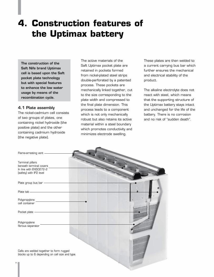
Cells are welded together to form rugged blocks up to 6 depending on cell size and type.
ed nd type.
Flame-arresting vent
Terminal pillars beneath terminal covers In line with EN50272-2 (safety) with IP2 level
Plate group bus bar
Polypropylene cell container
Polypropylene fibrous separator
Pocket plate
Plate tab
4.2 SeparationThe separator is a key feature of the Uptimax battery. It is a polypropylene fibrous material which has been used and proven by Saft in the Ultima ultra-low maintenance product over more than 20 years and has been further developed for this product to give the features required. Using this separator, the distance between the plates is carefully controlled to give the necessary gas retention to provide the level of recombination required. By providing a large spacing between the positive and negative plates and a generous quantity of electrolyte between plates, the possibility of thermal runaway, a problem with VRLA cells, is eliminated.
4.3 ElectrolyteThe electrolyte used in Uptimax, which is a solution of potassium hydroxide and lithium hydroxide, is optimized to give the best combination of performance, life and energy efficiency over a wide operational temperature range.
The concentration is such as to allow the cell to be operated to temperature extremes as low as - 20°C (- 4°F) and as high as + 50°C (+122°F). This allows the very high temperature fluctuations found in certain remote regions to be accommodated. For continuous temperatures below - 20°C (- 4°F) a special high density electrolyte can be used. It is an important consideration of Uptimax, and indeed all nickel-cadmium batteries, that the electrolyte does not change during charge and discharge. It retains its ability to transfer ions between the cell plates irrespective of the charge level. In most applications the electrolyte will retain its effectiveness for the life of the battery and will never need replacing.
4.4 Terminal pillarsShort terminal pillars are welded to the plate bus bars using a well-proven battery construction method. These posts are manufactured from steel bar, internally threaded for bolting on connectors and are nickel-plated.
The terminal pillar to lid seal is provided by a compressed visco-elastic sealing surface held in place by compression lock washers. This assembly is designed to provide satisfactory sealing throughout the life of the product.
4.5 Venting systemUptimax is fitted with a flame-arresting flip-top vent to simplify topping-up and is supplied with a transportation plug to ensure safe transportation.
4.6 Cell containerUptimax is built up using the well-proven Saft block battery construction. The tough polypropylene containers are welded together by heat sealing and the assembly of the blocks is completed by a clip-on terminal cover which gives protection to IP2X according to EN 60529 standard for the conductive parts.
8

Complete reliabilityDoes not suffer from the sudden death failure due to internal corrosion associated with other battery technologies.
Long cycle lifeThe Uptimax battery has a long cycle life even when the charge/discharge cycle involves 100 % depth of discharge (see section 6.7 Cycling).
Exceptionally long lifetimeA lifetime in excess of twenty years is achieved by Uptimax in many applications, and at elevated temperatures it has a lifetime unthinkable for other widely available battery technologies.
Low maintenanceWith its special recombination separator and generous electrolyte reserve, Uptimax reduces the need for topping-up with water. Only one topping-up operation is necessary during its entire service life.
Wide operating temperature rangeUptimax has an electrolyte which allows it to have a normal operating temperature of from - 20°C to + 40°C (- 4°F to +104°F), and accept extreme temperatures, ranging from as low as -40°C to + 70°C (-40°F to +158°F) (see section 4.3 Electrolyte).
Fast rechargeUptimax can be recharged at high currents which allow very fast recharge times to be achieved.
Resistance to mechanical abuseUptimax is designed to have the mechanical strength required to withstand all the harsh treatment associated with transportation over difficult terrain (see section 8.2 Mechanical abuse).
High resistance to electrical abuseUptimax will survive abuse which would destroy a lead acid battery, for example overcharging, deep discharging, and high ripple currents (see section 8.1 Electrical abuse).
Simple installationUptimax can be used with a wide range of stationary and mobile applications as it produces no corrosive vapors, uses corrosion-free polypropylene containers and has a simple bolted connector assembly system (see section 10 Installation and operating instructions).
Well-proven pocket plate constructionSaft has nearly 100 years of manufacturing and application experience with respect to the nickel-cadmium pocket plate
product, and this expertise has been built into the twenty-plus years’ design life of the Uptimax product (see section 4 Construction features of the Uptimax battery).
Extended storageWhen stored in the filled and charged state in normal condition, Uptimax can be stored for up to 2 years (see section 10 Installation and operating instructions).
Environmentally safeSaft operates a dedicated recycling center to recover the nickel, cadmium, steel and plastic used in the battery (see section 12 Disposal and recycling).
Low life-cycle costWhen all the factors of lifetime, low maintenance requirements, simple installation and storage and resistance to abuse are taken into account, Uptimax becomes the most cost effective solution for many professional applications.
5. Benefits of the Uptimax battery
9

10
6.1 CapacityThe Uptimax battery capacity is rated in ampere-hours (Ah) and is the quantity of electricity at +20°C (+68°F) which it can supply for a 5 hour discharge to 1.0 V/cell after being fully charged. This figure is in agreement with the IEC 62259 standard.
According to the IEC 62259, 0.2 C5 A is also expressed as 0.2 It A. The reference test current (It) is expressed as: Cn Ah 1 hwhere: Cn is the rated capacity
declared by the manufacturer in ampere-hours (Ah), and
n is the time base in hours (h) for which the rated capacity is declared.
In practice, Uptimax is used in floating conditions and so the tabular data is based upon cell performance after several months of floating. This eliminates certain correction factors which need to be used when sizing batteries with conventional fully charged open cell data (see section 9 Battery sizing principles).
6.2 Cell voltageThe cell voltage of nickel-cadmium cells results from the electrochemical potentials of the nickel and the cadmium active materials in the presence of the potassium hydroxide electrolyte. The nominal voltage is 1.2 V.
6.3 Internal resistanceThe internal resistance of a cell varies with the type of service and the state of charge and is, therefore, difficult to define and measure accurately.
The most practical value for normal applications is the discharge voltage response to a change in discharge current.
The internal resistance of an Uptimax cell depends on the performance type and at normal temperature has the values given in the product literature for fully charged cells.
For lower states of charge the values increase. For cells 50 % discharged the internal resistance is about 20 % higher, and when 90 % discharged, it is about 80 % higher. The internal resistance of a fully discharged cell has very little meaning.
Reducing the temperature also increases the internal resistance, and at 0°C (+32°F), the internal resistance is about 40 % higher.
The internal resistance of a block battery cell depends on the performance type.
6. Operating features
I t A =

11
6.4 Effect of temperature on performance
Variations in ambient temperature affect the performance of Uptimax and this needs to be taken into account when sizing the battery.
Low temperature operation has the effect of reducing the performance but the higher temperature characteristics are similar to those at normal temperatures. The effect of temperature is more marked at higher rates of discharge.
The factors which are required in sizing a battery to compensate for temperature variations are given in a graphical form in Figure 1(a) L type and, Figure 1(b) M type for operating temperature - 20°C to + 40°C (- 4°F to +104°F).
6.5 Short-circuit valuesThe typical short-circuit value in amperes for an Uptimax cell is approximately 6 times the ampere-hour capacity for an L type, 11 times the ampere-hour capacity for an M type. The Uptimax battery is designed to withstand a short-circuit current of this magnitude for many minutes without damage.
1.1
1.0
0.9
0.8
0.7
0.6
0.5
0.4-20°C -10°C 0°C +10°C +20°C +30°C +40°C-4°F +14°F +32°F +50°F +68°F +86°F +104°F
Typical de-rating factors for publishedperformance data for cells in floating applications
30 min rate
5 hour rate
1 hour rate
De-rating factor
Temperature
1 hour rate
Typical de-rating factors for publishedperformance data for cells in floating applications
De-rating factor
5 hour rate
Temperature
1.2
1.0
0.8
0.6
0.4
0.2-20°C -10°C 0°C +10°C +20°C +30°C +40°C-4°F +14°F +32°F +50°F +68°F +86°F +104°F
Figure 1(a): Temperature de-rating factors for L type cell for cell final voltage 1.00 V.
Figure 1(b): Typical de-rating factors for M type cell for cell final voltage 1.00 V.

12
6.6 Open circuit lossThe state of charge of Uptimax on open circuit slowly decreases with time due to self-discharge. In practice this decrease is relatively rapid during the first two weeks but then stabilizes to about 2 % per month at + 20°C (+ 68°F).
The self-discharge characteristics of a nickel-cadmium cell are affected by the temperature. At low temperatures the charge retention is better than at normal temperature and so the open circuit loss is reduced. However, the self-discharge is significantly increased at higher temperatures.
The open circuit loss for Uptimax for the standard temperature and the extremes of the normal operating range is shown in Figure 2 for a one year period.
6.7 CyclingUptimax is a low maintenance product and therefore is used generally in stationary and not continuous cycling applications. Nevertheless, it is designed using conventional pocket plate electrode technology and has therefore an equivalent cycling capability to the standard product.
If Uptimax is used in a deep cycling application which requires a fast recharge, there will be significant gas evolved and the low maintenance properties of the product will be severely reduced. However, there are cycling applications where Uptimax can be beneficial. This will depend on the frequency and depth of discharge involved.
°°
°°
°°
Figure 2: Typical open circuit loss variation with time.

6.8 Water consumptionThe Uptimax battery works on the oxygen recombination principle and therefore has a much reduced water consumption. In practice, for the recommended charging voltages, Uptimax has a level of recombination of more than 90 %. This compares to the level of recombination found in equivalent vented pocket plate cells of 30 % to 35 %. Thus Uptimax has a water usage reduced by a factor of up to 10 times of that of an open flooded cell. This means that at suitable charging voltages, Uptimax will need only one topping-up operation during its entire service life.
However, not all needs are the same for water replenishment under different and more difficult charging conditions.
6.9 Gas evolutionThe gas evolution is a function of the amount of water electrolyzed into hydrogen and oxygen which is not involved in the recombination cycle. The electrolysis of 1 cm3 of water produces about 1865 cm3 of gas mixture and this gas mixture is in the proportion of 2/3 hydrogen and 1/3 oxygen.Thus the electrolysis of 1 cm3 of water produces about 1243 cm3 of hydrogen.
As stated in section 6.8, under normal recommended float conditions Uptimax has a recombination level of more than 90 % and so the amount of water which is electrolyzed into gas is small. Typically an Uptimax cell will electrolyze about 0.002 cm3 of water per Ah of cell capacity per day. This value will be smaller or larger depending on the float voltage value. Thus a typical value of gas emission would be 4.5 cm3 per Ah of cell capacity per day, or 3 cm3 of hydrogen per Ah of cell capacity per day.
13
14
In order to ensure that the low maintenance properties of the Uptimax battery are achieved, it is necessary to control the charge input to the battery to minimize the rate of water loss during the life of the product.
It is important therefore that the recommended charge conditions are complied with. However, Uptimax has a high technology, low maintenance concept in allowing the possibility of replenishment of water in severe applications where excessive water loss is unavoidable.
7.1 Charging methodsUptimax batteries may be charged quickly and simply by the following methods:
a) Two level constant potential charging
The initial stage of two-rate constant potential charging consists of a first charging stage to a maximum voltage of 1.45 ± 0.01 V/cell.
Alternatively, if a faster rate of recharge is required, a voltage limit of 1.55 V/cell with a current limit of 0.1 C5 A can be used. However, if frequent recharges are required this will increase the rate of water loss and gas generation.
After this first stage the charger should be switched to a second maintenance stage at a float voltage of 1.43 ± 0.01 V/cell. After a prolonged mains failure the first stage should be reapplied manually or automatically.
b) Single level float chargingUptimax batteries are float charged at 1.43 ± 0.01 V/cell from a fully discharged condition to a high state of charge. This is detailed in section 7.2 and about 90 % of the capacity will be available after 15 hours of charge even at + 40°C (+104°F).
7. Battery charging

7.2 Charge acceptanceThe performance data sheets for Uptimax are based upon several months’ floating and so are for fully float charged cells.
A discharged cell will take a certain time to achieve this and Figure 3 gives the capacity available for the two principal charging voltages recommended for Uptimax, 1.43 V/cell and 1.45 V/cell, during the first 30 hours of charge from a fully discharged state.
If the application has a particular recharge time requirement then this must be taken into account when calculating the battery.
15
1.45 V per cell at +20°C (+68°F) 0.1C5
1.43 V per cell at +20°C (+68°F) 0.1C5
1.45 V per cell at +20°C (+68°F) 0.2C5
0 5 10 15 20 25 30 35
100%
90%
80%
70%
60%
50%
40%
30%
20%
10%
0%
% of the rated capacity
Charging time (hours)
*For charging voltages higher than 1.45 V/cell, a current limit of 0.1 C5A is recommended
Figure 3(a): Available capacity after constant voltage charge Available charge current 0.1C5 A or 0.2C5 A, for L type cell.
1.45 V per cell at +20°C (+68°F) 0.1C5
1.43 V per cell at +20°C (+68°F) 0.1C5
1.45 V per cell at +20°C (+68°F) 0.2C5
0 5 10 15 20 25 30 35
100%
90%
80%
70%
60%
50%
40%
30%
20%
10%
0%
% of the rated capacity
Charging time (hours)
Figure 3(b): Available capacity after constant voltage charge Available charge current 0.1C5 A or 0.2C5 A, for M type cell.
*For charging voltages higher than 1.45 V/cell, a current limit of 0.1 C5A is recommended
16
7.3 Charge efficiencyThe charge efficiency of Uptimax is dependent on the state of charge of the battery and the temperature. For much of its charge profile it is recharged at a high level of efficiency. In general, at states of charge less than 80 % the charge efficiency remains high, but as the battery approaches a fully charged condition, the charging efficiency falls off.
7.4 Temperature effectsAs the temperature increases, then the electrochemical behaviour becomes more active and so, for the same charge voltage, the current at the end of charge increases. This end of charge increases in the current helps to compensate for the variation in charge efficiency at high temperatures and allows a high state of charge to be achieved. For this reason it is not needed to apply temperature compensation of the charge voltage used for ambient temperatures above 10°C (50°F). To minimize water consumption at sustained operation at high temperatures, temperature compensation can be used, to reduce the increase of current at higher temperatures.
As the temperature is reduced, then the reverse occurs and it is recommended that, for application where the ambient temperature falls below 10°C (50°F) for sustained periods, temperature compensation of the charge voltage should be used to maintain the end of charge current at a constant value.
When temperature compensation is used the change in voltage required per cell, or “temperature compensation”, should be between -2 mV and -3.5 mV per °C (-1.12 mV and -1.96 mV per °F). The recommended value per cell is -2.5 mV per °C (-1.4 mV per °F).
If main operation is at high temperature, use -2 mV per °C (-1.12 mV per °F).
If the fast recharge at low temperature (below -10°C (14°F) ) is very important, use -3.5 mV per °C (-1.96 mV per °F).
8.1 Electrical abuse8.1.1 Ripple effectsThe nickel-cadmium battery is tolerant to high ripple from standard charging systems. Uptimax accepts ripple currents up to 0.2 C5 A I eff. In general, any commercially available charger or generator can be used for commissioning or maintenance charging of Uptimax.
8.1.2 Over-dischargeIf more than the designed capacity is taken out of a battery then it becomes over-discharged. This is considered to be an abuse situation for a battery and should be avoided.
In the case of lead acid batteries this will lead to failure of the battery and is unacceptable.
The Uptimax battery is designed to make recovery from this situation possible.
8.1.3 OverchargeOvercharge is the effect of forcing current through a battery when it is fully charged. This can be damaging for a lead acid battery, and due to its starved electrolyte technology, seriously reduce the life of a VRLA battery.
In the case of Uptimax, with its generous electrolyte reserve, a small degree of overcharge will not significantly alter the maintenance period. In the case of excessive overcharge, water replenishment is required but there will be no significant effect on the life of the battery.
8.2 Mechanical abuse8.2.1 Shock loadsThe Uptimax block battery concept has been tested to IEC 68-2-29 (bump tests at 5 g, 10 g and 25 g) and IEC 77 (shock test 3 g), where g = acceleration.
8.2.2 Vibration resistanceThe Uptimax block battery concept has been tested to IEC 77 for 2 hours at 1 g, where g = acceleration.
8.2.3 External corrosionUptimax nickel-cadmium cells are manufactured in durable polypropylene, all external metal components are nickel-plated and these components are protected by an anti-corrosion oil and a rigid plastic cover.
8. Special operating factors17

18
9. Battery sizing principles in stationary applications
There are a number of methods which are used to size nickel-cadmium batteries for standby floating applications. The method employed by Saft is the IEEE 1115 recommendation which is accepted internationally. This method takes into account multiple discharges, temperature de-rating, performance after floating and the voltage window available for the battery.
A significant advantage of the nickel-cadmium battery compared to a lead acid battery, is that it can be fully discharged without any inconvenience in terms of life or recharge. Thus, to obtain the smallest and least costly battery, it is an advantage to discharge the battery to the lowest practical value in order to obtain the maximum energy from the battery.
The principle sizing parameters which are of interest are:
9.1 The voltage windowThis is the maximum voltage and the minimum voltage at the battery terminals acceptable for the system. In battery terms, the maximum voltage gives the voltage which is available to charge the battery, and the minimum voltage gives the lowest voltage acceptable to the system to which the battery can be discharged. In discharging the nickel-cadmium battery, the cell voltage should be taken as low as possible in order to find the most economic and efficient battery.
9.2 Discharge profileThis is the electrical performance required from the battery for the application. It may be expressed in terms of amperes for a certain duration, or it may be expressed in terms of power, in watts or kW, for a certain duration. The requirement may be simply one discharge or many discharges of a complex nature.
9.3 TemperatureThe maximum and minimum temperatures and the normal ambient temperature will have an influence on the sizing of the battery. The performance of a battery decreases with decreasing temperature and sizing at a low temperature increases the battery size. Temperature de-rating curves are produced for all cell types to allow the performance to be recalculated.

9.4 State of charge or recharge timeSome applications may require that the battery shall give a full duty cycle after a certain time after the previous discharge. The factors used for this will depend on the depth of discharge, the rate of discharge, and the charge voltage and current. A requirement for a high state of charge does not justify a high charge voltage if the result is a high end of discharge voltage.
9.5 AgeingSome customers require a value to be added to allow for the ageing of the battery over its lifetime. This may be a value required by the customer, for example 10 %, or it may be a requirement from the customer that a value is used which will ensure the service of the battery during its lifetime. The value to be used will depend on the discharge rate of the battery and the conditions under which the discharge is carried out.
9.6 Floating effectWhen a nickel-cadmium cell is maintained at a fixed floating voltage over a period of time, there is a decrease in the voltage level of the discharge curve. This effect begins after one week and reaches its maximum in about 3 months. It can only be eliminated by a full discharge/charge cycle, and it cannot be eliminated by a boost charge. It is therefore necessary to take this into account in any calculations concerning batteries in float applications.
This is used in the IEEE sizing method and the published data for Uptimax.
As the effect of reducing the voltage level is to reduce the autonomy of the battery, the effect can be considered as reducing the performance of the battery and so performance down-rating factors are used.
19

10. Installation and operating instructions
Important recommendations
Never allow an exposed flame or spark near the batteries, particularly while charging.
Never smoke while performing any operation on the battery.
For protection, wear rubber gloves, long sleeves, and appropriate splash goggles or face shield.
The electrolyte is harmful to skin and eyes. In the event of contact with skin or eyes, wash immediately with plenty of water. If eyes are affected, flush with water, and obtain immediate medical attention.
Remove all rings, watches and other items with metal parts before working on the battery.
Use insulated tools. Avoid static electricity and take measures for protection against electric shocks.
Discharge any possible static electricity from clothing and/or tools by touching an earth-connected part “ground” before working on the battery.
10.1 Receiving the shipment
Unpack the cells immediately upon arrival. Do not overturn the package. Check the packages and cells for transport damage.
The cells are shipped filled and charged, and are ready for immediate use.
Transport seals are located under the lid of each vent and they must be removed prior to charging.
The cells must never be charged with the plastic transport seals in place as this is dangerous and can cause permanent damage.
10.2 StorageStore the battery indoors in a dry, clean, cool location (0°C to + 30°C /+ 32°F to + 86°F) and well ventilated space on open shelves.
Storage of a filled battery at temperatures above + 30°C (+ 86°F) can result in loss of capacity. This can be as much as 5 % per 10°C (18°F) above + 30°C (+ 86°F) per year.
Do not store in direct sunlight or expose to excessive heat.
Uptimax cells are supplied filled with electrolyte and charged, they can be stored in this condition for maximum 24 months.
Never drain the electrolyte from the cells.
When deliveries are made in cardboard boxes, store without opening the boxes.
When deliveries are made in plywood boxes, open the boxes before the storage. The lid and the packing material on top of the cells must be removed.
10.3 Installation10.3.1 LocationInstall the battery in a dry and clean room. Avoid direct sunlight and heat. The battery will give the best performance and maximum service life when the ambient temperature is between +10°C to + 30°C (+ 50°F to + 86°F).
20
Type UP1 L and UP1 M

10.3.2 VentilationDuring the last part of charging, the battery is emitting gases (oxygen and hydrogen mixture). At normal float charge the gas evolution is very small but some ventilation is necessary.
Note that special regulations for ventilation may be valid in your area depending on the application.
10.3.3. MountingVerify that cells are correctly interconnected with the appropriate polarity. The battery connection to load should be with nickel-plated cable lugs. Apply a thin layer of anti-corrosion oil to protect the connectors and terminals from corrosion.
Recommended torques for terminal bolts are:
•M6 = 11 ± 1.1 N.m (97.4 ± 9.7 lbf.in)
•M8 = 20 ± 2 N.m (177.0 ± 17.7 lbf.in)
•M10 = 30 ± 3 N.m (265.5 ± 26.6 lbf.in)
The connectors and terminal should be corrosion-protected by coating with a thin layer of anti-corrosion oil.
Remove the transport seals and close the vent plugs.
10.3.4 ElectrolyteWhen checking the electrolyte levels, a fluctuation in level between cells is not abnormal and is due to the different amounts of gas held in the separators of each cell. The level should be at least 15 mm above the minimum level mark (lower) and there is normally no need to adjust it.
In case of spillage of electrolyte during the transport, the cells have to be topped up with E22 electrolyte.
Do not top-up prior to initial charge.
10.4 CommissioningVerify that the transport seals are removed, the vents are closed, and the ventilation is adequate during this operation. A good commissioning is important.
Cells stored up to 6 months:A commissioning charge is normally not required and the cells are ready for immediate use.
Cells stored more than 6 months and up to 2 years:
A commissioning charge is necessary:
• Constant current charge:Charge for 16 h at 0.1 C5 A recommended (see Installation and operating instructions sheet).Note: At the end of charge, the cell voltage may reach the level of 1.85 V, thus the charger shall be able to supply such a voltage.
When the charger maximum voltage setting is too low to supply constant current charging, divide the battery into two parts to be charged individually at constant current.
21
• Constant voltage charge:Charge for 1.65 V/cell for a minimum of 30 h with current limited to 0.1 C5 A (see Installation and operating instructions sheet).
If these methods are not available, then charging may be carried out at lower voltages, 1.50 V/cell for 72 hours minimum.Note: For capacity test purposes, the battery has to be charged in accordance with IEC 62259 section 7 (7.1 & 7.2).
10.5 Charging in serviceThe recommended charging voltages for continuous parallel operation, with occasional battery discharges, are: Two level charge:
• float level: 1.43 ± 0.01 V/cell
• high rate (boost) level: 1.45 ± 0.01 V/cell Single level charge: 1.43 ± 0.01 V/cell
10.6 Periodic maintenanceUptimax is a low maintenance battery and requires the minimum of maintenance.
As a periodic maintenance, the following is recommended:
Keep the battery clean using only water. Do not use a wire brush or solvents of any kind. Check visually the electrolyte level.
Never let the level fall below the minimum level mark (lower). Use only distilled or de-ionized water to top-up.
Topping-up of the Uptimax battery shall be carried out when battery is fully charged.
Experience will tell the time interval between topping-up.
Note: There is no need to check the electrolyte density periodically. Interpretation of density measurements is difficult and could be misleading.
Check the charging voltage. In parallel operation, it is of great importance that the recommended charging voltage remains unchanged. The charging voltage should be checked and recorded at least once yearly. If a cell float voltage is found below 1.35 V, high-rate charge recommended to apply to the cell concerned. Check every two years that all connectors are tight. The connectors and terminal bolts should be corrosion-protected by coating with a thin layer of anti-corrosion oil. High water consumption of the battery is usually caused by improper voltage setting of the charger.
22
11. Maintenance of Uptimax batteries in service
In a correctly designed stationary application, Uptimax requires the minimum of attention.
However, it is good practice with any system to carry out an inspection of the system once per year or at the recommended topping-up interval period to ensure that the charging system, the battery and the ancillary electronics are all functioning correctly.
When this system service is carried out, it is recommended that the following actions should be taken:
Cell electrolyte levels should be checked visually to ensure that the level is above the minimum and if necessary the cells should be topped-up. Use only distilled or deionized water.
The batteries should also be checked for external cleanliness, and if necessary cleaned with a damp brush using water. Do not use a wire brush or solvents of any kind. Vent plugs can be rinsed in clean water if necessary.
All the connectors must be tight. The connectors and terminal bolts should be corrosion-protected by coating with a thin layer of anti-corrosion oil.
23

In a world where autonomous sources of electric power are ever more in demand, Saft batteries provide an environmentally responsible answer to these needs. Environmental management lies at the core of Saft’s business and we take care to control every stage of a battery’s life cycle in terms of potential impact. Environmental protection is our top priority, from design and production through end-of-life collection, disposal and recycling.
Our respect for the environment is complemented by an equal respect for our customers. We aim to generate confidence in our products, not only from a functional standpoint, but also in terms of the environmental safeguards that are built into their life cycle. The simple and unique nature of the battery components make them readily recyclable and this process safeguards valuable natural resources for future generations.
In partnership with collection agencies worldwide, Saft organizes retrieval from pre-collection points and the recycling of spent Saft batteries. Saft’s collection network can be found on our web site:
www.saftbatteries.com
Ni-Cd batteries must not be discarded as harmless waste and should be treated carefully in accordance with local and national regulations. Your Saft representative can assist with further information on these regulations and with the overall recycling procedure.
12. Disposal and recycling
24


Africa Saft export sales dpt, France Tel. : +33 1 49 93 19 18 Fax : +33 1 49 93 19 56
Argentina Energia Alcalina, Buenos Aires Tel. : +54 11 4334 9034/35Fax : +54 11 4342 5024
Australia Saft Australia Pty Ltd, Seven Hills Tel. : +61 2 9674 0700Fax : +61 2 9620 9990
Austria Statron GmbH, Wien Tel. : +43 1 617 40 60 Fax : +43 1 617 40 60/40
Belgium AEG Belgium SA, Brussels Tel. : +32 2 529 6543 Fax : +32 2 529 6449
Brazil Adelco Sistemas de Energia Ltda., São Paulo Tel. : +55 11 4199 7500 Fax : +55 11 4161 5307
CanadaPlease contact USA office
China Saft (Zhuhai Free Trade Zone) Batteries Co Ltd, ShanghaiTel. : +86 21 5866 6405 Fax : +86 21 5866 6403
Czech Republic Saft Ferak a.s., Prague Tel. : +420 257 013 260 Fax : +420 257 013 261
Denmark Scansupply A/S, Birkeroed Tel. : +45 45 82 50 90Fax : +45 45 82 54 40
Finland HansaBattery Oy, Espoo Tel. : +358 207 63 1883 Fax : +358 207 63 1889
France Saft France, Bagnolet Tel. : +33 1 49 93 19 18 Fax : +33 1 49 93 19 64
Germany Saft Batterien GmbH, Nürnberg Tel. : +49 911 94 174-0 Fax : +49 911 426 144
Hong Kong (Stationary, railway, telecom and renewable applications)Saft Hong Kong Ltd.,Kowloon Tel. : +852 3568 7066 Fax : +852 2798 0619
India sub continent AMCO-Saft India Ltd, Bangalore, India Tel. : +91 80 2 363 7790 Fax : +91 80 2 363 7716
Italy Saft Batterie Italia S.r.l., Segrate (Milano) Tel. : +39 02 89 28 07 47 Fax : +39 02 89 28 07 62
Japan Sumitomo Corp., Tokyo Tel. : +81 3 5144 9082 Fax : +81 3 5144 9267
Korea Enersys Korea Co. Ltd, Seoul Tel. : +82 2501 0033 Fax : +82 2501 0034
Mexico Troop y Compania, SA de CV, Mexico Tel. : +52 55 50 82 10 30 Fax : +52 55 50 82 10 39
Middle East Saft Nife ME Ltd, Limassol, Cyprus Tel. : +357 25 820040 Fax : +357 25 748492
Netherlands Saft Batterijen B.V., Eindhoven Tel. : +31 40 272 1900 Fax : +31 40 272 1904
Norway Saft AS, Osteraas Tel. : +47 6716 4160 Fax : +47 6716 4170
Russia ZAO Ancor, Moscow Tel. : 7495 788 5204 Fax : 7898 958 1323
Singapore Saft Batteries Pte Ltd, Singapore Tel. : +65 6512 1500 Fax : +65 6749 7282
Spain Saft Baterias S.L., San Sebastian de los Reyes Tel. : +34 916 593 480 Fax : +34 916 593 490
Sweden Saft AB, Oskarshamn Tel. : +46 491 680 00 Fax : +46 491 681 80
Switzerland Statron AG, Mägenwil Tel. : +41 62 887 4 887 Fax : +41 62 887 4 888
United Kingdom Saft Ltd, Harlow Tel. : +44 1279 772 550 Fax : +44 1279 420 909
USA Saft America Inc.,(Stationary and renewable applications) North Haven (CT) Tel. : +1 203 239 4718 Fax : +1 203 234 7598(Telecom applications) Valdosta (GA) Tel. : +1 229 245 2854 Fax : +1 229 247 8486
(Rail/Transit Sales) Cockeysville (MD) Tel. : +1 410 771 32 00 Fax : +1 410 771 11 44
Venezuela Corporación INTELEC C.A., Caracas Tel. : +58 212 963 1122 Fax : +58 212 961 4908
Western Asia Export sales dpt, Sweden Tel. : +46 491 680 00 Fax : +46 491 681 80
Saft Industrial Battery Group 12, rue Sadi Carnot 93170 Bagnolet – France Tel. : +33 (0)1 49 93 19 18 Fax : +33 (0)1 49 93 19 64
www.saftbatteries.com
Doc N˚ 21792-2-0610 Edition: June 2010 Data in this document is subject to change without notice and becomes contractual only after written confirmation.
Photo credits: © Digital Vision, Getty Images, Photodisc, Peet Simard, Saft.
Société anonyme au capital de 31 944 000 RCS Bobigny B 383 703 873
Produced by Arthur Associates Limited.
Saft is committed to the highest standards of environmental stewardship.As part of its environmental commitment, Saft gives priority to recycled raw materials over virgin raw materials, reduces its plants’ releases to air and water year after year, minimizes water usage, reduces fossil energy consumption and associated CO2 emissions, and ensures that its customers have recycling solutions available for their spent batteries.
Regarding industrial Ni-Cd batteries, Saft has had partnerships for many years with collection companies in most EU countries, in North America and in other countries. This collection network receives and dispatches our customers’ batteries at the end of their lives to fully approved recycling facilities, in compliance with the laws governing trans-boundary waste shipments.This collection network is undergoing minor adaptations to meet the requirements of the EU batteries directive. A list of our collection points is available on our web site.In other countries, Saft assists users of its batteries in finding environmentally sound recycling solutions. Please contact your sales representative for further information.


![Removal of Heavy Metals (Cd, Cu, Ni) by Electrocoagulationijesd.org/vol6/630-W0028.pdf · Removal of Heavy Metals (Cd, Cu, Ni) by Electrocoagulation . ... [14] were also studied the](https://static.fdocuments.in/doc/165x107/5aa58f367f8b9a517d8d665a/removal-of-heavy-metals-cd-cu-ni-by-ele-of-heavy-metals-cd-cu-ni-by-electrocoagulation.jpg)