Ups
91
Operation and Reference Guide Second Edition (October 1999) Part Number 341252-002 Compaq Computer Corporation
-
Upload
adrian-oros -
Category
Documents
-
view
212 -
download
0
description
UPs compaque
Transcript of Ups

2000 Series UPSOperation and Reference Guide
Second Edition (October 1999)Part Number 341252-002Compaq Computer Corporation

NoticeThe information in this publication is subject to change without notice.
COMPAQ COMPUTER CORPORATION SHALL NOT BE LIABLE FOR TECHNICAL OREDITORIAL ERRORS OR OMISSIONS CONTAINED HEREIN, NOR FOR INCIDENTAL ORCONSEQUENTIAL DAMAGES RESULTING FROM THE FURNISHING, PERFORMANCE, ORUSE OF THIS MATERIAL. THIS INFORMATION IS PROVIDED “AS IS” AND COMPAQCOMPUTER CORPORATION DISCLAIMS ANY WARRANTIES, EXPRESS, IMPLIED ORSTATUTORY AND EXPRESSLY DISCLAIMS THE IMPLIED WARRANTIES OFMERCHANTABILITY, FITNESS FOR PARTICULAR PURPOSE, GOOD TITLE AND AGAINSTINFRINGEMENT.
This publication contains information protected by copyright. No part of this publication may bephotocopied or reproduced in any form without prior written consent from Compaq ComputerCorporation.
© 1999 Compaq Computer Corporation.
All rights reserved. Printed in the U.S.A.
The software described in this guide is furnished under a license agreement or nondisclosure agreement.The software may be used or copied only in accordance with the terms of the agreement.
Compaq, Deskpro, Fastart, Compaq Insight Manager, Systempro, Systempro/LT, ProLiant, ROMPaq,QVision, SmartStart, NetFlex, QuickFind, PaqFax, ProSignia, registered United States Patent andTrademark Office.
Netelligent, Systempro/XL, SoftPaq, QuickBlank, QuickLock are trademarks and/or service marks ofCompaq Computer Corporation.
Neoserver is a trademark of Compaq Information Technologies Group.
Microsoft, MS-DOS, Windows, and Windows NT are registered trademarks of Microsoft Corporation.
Pentium is a registered trademark and Xeon is a trademark of Intel Corporation.
Other product names mentioned herein may be trademarks and/or registered trademarks of theirrespective companies.
Compaq 2000 Series UPS Operation and Reference GuideSecond Edition (October 1999)Part Number 341252-002

Contents
About This GuideText Conventions.......................................................................................................viiSymbols in Text....................................................................................................... viiiSymbols on Equipment............................................................................................ viiiPrecautions..................................................................................................................ixGetting Help ................................................................................................................x
Compaq Technical Support ..................................................................................xCompaq Website..................................................................................................xiCompaq Authorized Reseller...............................................................................xi
Chapter 1Overview
Compaq 2000 Series UPS Models........................................................................... 1-2Front Panels ............................................................................................................. 1-3Rear Panels .............................................................................................................. 1-4Standard UPS Features ............................................................................................ 1-6
Communications Port ....................................................................................... 1-7Power Management Software........................................................................... 1-7Hardware Option Cards .................................................................................... 1-8Network Transient Protector........................................................................... 1-10
Warranties.............................................................................................................. 1-10$25,000 Computer Load Protection Guarantee .............................................. 1-10Pre-Failure Battery Warranty ......................................................................... 1-10
Chapter 2Installation
Installation Requirements ........................................................................................ 2-2Item(s) not supplied with the UPS kit............................................................... 2-2Item(s) supplied with the UPS kit..................................................................... 2-2

iv Compaq 2000 Series UPS Operation and Reference Guide
Installationcontinued
Before Starting the UPS........................................................................................... 2-3Connecting the External Battery Module.......................................................... 2-3Connecting to the Communications Port .......................................................... 2-4Connecting the Network Transient Protector.................................................... 2-5
Starting the UPS....................................................................................................... 2-6Checking the Battery Recharge Date Label ...................................................... 2-6Connecting the UPS to Utility Power ............................................................... 2-7Connecting Devices to the UPS........................................................................ 2-7Powering up the UPS........................................................................................ 2-8
Completing the Installation.................................................................................... 2-10Placing the UPS in Operate mode................................................................... 2-10
Chapter 3Operation
Precautions............................................................................................................... 3-2Modes of Operation ................................................................................................. 3-2Front Panel Controls ................................................................................................ 3-3Front Panel Indicators .............................................................................................. 3-5
Front Panel LEDs in the Standby and Operate Modes...................................... 3-5Overcurrent Protection............................................................................................. 3-8Placing the UPS in Operate Mode ........................................................................... 3-8Returning to Standby Mode ..................................................................................... 3-9Initiating a Self-test................................................................................................ 3-11Audio Alarm .......................................................................................................... 3-12
Silencing an Audio Alarm .............................................................................. 3-13
Chapter 4Configuration
Placing the UPS in Configure Mode........................................................................ 4-2Configuration Parameters and their LED Indicators ................................................ 4-3Changing Configuration Parameters ........................................................................ 4-6Optimizing Battery Life by Matching the Utility Voltage ....................................... 4-7
Chapter 5Battery Maintenance
Precautions............................................................................................................... 5-2Charging Batteries.................................................................................................... 5-3When to Replace Batteries ....................................................................................... 5-3Pre-Failure Battery Warranty................................................................................... 5-4Obtaining a New Battery Module ............................................................................ 5-4

About This Guide v
Battery Maintenancecontinued
Replacing an External Battery Module.................................................................... 5-5Step 1: Preparing the UPS ................................................................................ 5-5Step 2: Removing the External Battery Module ............................................... 5-6Step 3: Installing a New Battery Module.......................................................... 5-7Step 4: Testing a New Battery Module............................................................. 5-8Step 5: Disposing of Used Battery Modules..................................................... 5-8
Care and Storage of Batteries .................................................................................. 5-9
Chapter 6Troubleshooting
Troubleshooting During Start .................................................................................. 6-2Troubleshooting After Start ..................................................................................... 6-3Repairing the UPS ................................................................................................... 6-5
Appendix ARegulatory Compliance Notices
Federal Communications Commission Notice ........................................................A-1Class A Equipment ...........................................................................................A-2Class B Equipment ...........................................................................................A-2Modifications....................................................................................................A-3Cables ...............................................................................................................A-3
Canadian Notice (Avis Canadien) ...........................................................................A-3Class A Equipment ...........................................................................................A-3Class B Equipment ...........................................................................................A-4
European Union Notice ...........................................................................................A-4Japanese Notice .......................................................................................................A-5Taiwanese Notice.....................................................................................................A-5Battery Replacement Notice ....................................................................................A-5
Appendix BElectrostatic Discharge
Grounding Methods .................................................................................................B-2

vi Compaq 2000 Series UPS Operation and Reference Guide
Appendix CSpecifications
Physical Specifications ............................................................................................C-2Input Specifications..................................................................................................C-3Output Specifications...............................................................................................C-4Output Specifications...............................................................................................C-5Overcurrent Protection.............................................................................................C-6Battery Specifications ..............................................................................................C-7Battery Runtime .......................................................................................................C-8Environmental Specifications ..................................................................................C-9
Index

About This Guide
This guide is designed to be used as step-by-step instructions for installationand as a reference for operation, troubleshooting, and future upgrades.
Text ConventionsThis document uses the following conventions to distinguish elements of text:
Keys Keys appear in boldface. A plus sign (+) betweentwo keys indicates that they should be pressedsimultaneously.
USER INPUT User input appears in a different typeface and inuppercase.
FILENAMES File names appear in uppercase italics.
Menu Options,Command Names,Dialog Box Names
These elements appear in initial capital letters.
COMMANDS,DIRECTORY NAMES,and DRIVE NAMES
These elements appear in uppercase.
Type When you are instructed to type information, typethe information without pressing the Enter key.
Enter When you are instructed to enter information, typethe information and then press the Enter key.

viii Compaq 2000 Series UPS Operation and Reference Guide
Symbols in TextThese symbols may be found in the text of this guide. They have the followingmeanings.
WARNING: Text set off in this manner indicates that failure to follow directions
in the warning could result in bodily harm or loss of life.
CAUTION: Text set off in this manner indicates that failure to follow directions
could result in damage to equipment or loss of information.
IMPORTANT: Text set off in this manner presents clarifying information or specific
instructions.
NOTE: Text set off in this manner presents commentary, sidelights, or interesting points
of information.
Symbols on EquipmentThese icons may be located on equipment in areas where hazardous conditionsmay exist.
Any surface or area of the equipment marked with these symbols
indicates the presence of electrical shock hazards. Enclosed area
contains no operator serviceable parts.
WARNING: To reduce the risk of injury from electrical shock hazards,
do not open this enclosure.
79 to 97 lb
36 to 44 kg
Any product or assembly marked with these symbols indicates that the
component exceeds the recommended weight for one individual to
handle safely.
WARNING: To reduce the risk of personal injury or damage to the
equipment, observe local occupational health and safety requirements
and guidelines for manual material handling.

About This Guide ix
Any RJ-45 receptacle marked with these symbols indicates a Network
Interface Connection.
WARNING: To reduce the risk of electrical shock, fire, or damage to
the equipment, do not plug telephone or telecommunications
connectors into this receptacle.
Any surface or area of the equipment marked with these symbols
indicates the presence of a hot surface or hot component. If this
surface is contacted, the potential for injury exists.
WARNING: To reduce the risk of injury from a hot component, allow
the surface to cool before touching.
Precautions
WARNING: There is a risk of electric shock from high earth conductor leakage
current when connecting multiple pieces of Information Technology Equipment
to Compaq 2000 Series Uninterruptible Power Systems (UPS):
The summation of the input power for multiple pieces of Information Technology
Equipment through the use of a UPS can result in high earth conductor leakage
current. For UPS products that have detachable AC power cords, the total
combined earth conductor leakage current should not exceed 3.5 mA.
WARNING: There is a risk of personal injury from the hazardous energy levels
associated with UPS batteries. The maintenance and replacement of batteries
must be carried out by qualified service personnel.

x Compaq 2000 Series UPS Operation and Reference Guide
WARNING: The 2000 Series UPS models weigh between 79 and 97 lb
(36 to 44 kg) when fully assembled.
T2000 and T2000j:
UPS 32 lb (15 kg) Battery 47 lb (21 kg)
T2400h and T2400h-NA:
UPS 34 lb (15 kg) Battery 63 lb (29 kg)
To reduce the risk of personal injury or damage to the equipment:
■ Observe local occupational health and safety requirements and guidelinesfor manual material handling.
■ Obtain adequate assistance to lift and stabilize the chassis duringinstallation or removal.
■ Remove the battery pack to reduce the overall weight of the product.
IMPORTANT: Please refer to the Important Safety Information (included with the
UPS kit) before installing this product.
Getting HelpIf you have a problem and have exhausted the information in this guide, youcan get further information and other help in the following locations.
Compaq Technical Support
You are entitled to free hardware technical telephone support for your productfor as long as you own the product. A technical support specialist will helpyou diagnose the problem or guide you to the next step in the warrantyprocess.
In North America, call the Compaq Technical Phone Support Center at1-800-OK-COMPAQ1. This service is available 24 hours a day, 7 days a week.
Outside North America, call the nearest Compaq Technical Support PhoneCenter. Telephone numbers for world wide Technical Support Centers arelisted on the Compaq website. You can access the Compaq website at:http://www.compaq.com
Be sure to have the following information available before you call Compaq:
1 For continuous quality improvement, calls may be recorded or monitored.

About This Guide xi
■ Technical support registration number (if applicable)
■ Product serial number(s)
■ Product model name(s) and number(s)
■ Applicable error messages
■ Add-on boards or hardware
■ Third-party hardware or software
■ Operating system type and revision level
■ Detailed, specific questions
Compaq Website
The Compaq website has information on this product as well as the latestdrivers and Flash ROM images. You can access the Compaq website at:http://www.compaq.com
Compaq Authorized Reseller
For the name of your nearest Compaq authorized reseller:
■ In the United States, call 1-800-345-1518.
■ In Canada, call 1-800-263-5868.
■ Elsewhere, access the Compaq website at:http://www.compaq.com

Chapter 1Overview
This chapter contains information on the following topics:
■ Compaq 2000 Series Uninterruptible Power System (UPS) models
■ 2000 Series UPS front panels
■ 2000 Series UPS rear panels
■ 2000 Series UPS features
■ Warranties

1-2 Compaq 2000 Series UPS Operation and Reference Guide
Compaq 2000 Series UPS ModelsThe 2000 Series includes the following UPS models:
Table 1-1 2000 Series UPS Models
UPS Model Part Number Comments
T2000 242688-005 Domestic; low voltage; Tower
T2000j 242688-295 Japanese; low voltage; Tower
T2400h 242688-006 International; high voltage; Tower
T2400h-NA 242688-007 Domestic; high voltage; Tower
Front Panels The 2000 Series UPS models are all tower configuration, with companionexternal battery modules.
1 2
4 3
Figure 1-1. Front panel configuration
1 UPS
2 Front panel LED display
3 External battery module
4 Button controls

Overview 1-3
Rear PanelsThe 2000 Series UPS models feature the following rear panel configurations:
9
1 2 3
4
5
6
78
10
Figure 1-2. Rear panel of T2000 and T2000j
1 Communications port 6 Power cord with 5-20p plug
2 Battery connector 7 Load segment 2
3 Load segment 3 8 10A circuit breakers
4 Option slot 9 Load segment 1
5 Network Transient Protector : External battery module

1-4 Compaq 2000 Series UPS Operation and Reference Guide
10AMP
1 2
3
4
5
6
789
10
Figure 1-3. Rear panel of T2400h
1 Communications port 6 Network Transient Protector
2 Battery connector 7 Load segment 3
3 IEC-320 power inlet 8 Load segment 2
4 10A circuit breaker 9 Load segment 1
5 Option slot : External battery module

Overview 1-5
10AMP
1 2
3
4
5
6
789
10
Figure 1-4. Rear panel of T2400h-NA
1 Communications port 6 Network Transient Protector
2 Battery connector 7 Load segment 3
3 IEC-320 power inlet 8 Load segment 2
4 10A circuit breaker 9 Load segment 1
5 Option slot : External battery module
Standard UPS FeaturesThe 2000 Series UPS models provide the following features:
■ Communications port for data exchange with the host computer
■ Power protection for loads up to 2000VA
■ Load segment control
■ Support for power management software
■ Support for Compaq hardware option cards that extend the powermanagement capabilities of the UPS
■ Network Transient Protector (for network surge protection)

1-6 Compaq 2000 Series UPS Operation and Reference Guide
Communications Port
The 2000 Series UPS models include a communications port that allows theUPS to exchange data with the host computer. Power management software(supplied by Compaq) gives users access to status reporting and powermanagement features.
CAUTION: Use only cables supplied by Compaq to connect the communicationsport to the host computer. Use of standard RS-232 cables may cause equipmentdamage.
Power Management Software
With each UPS, Compaq supplies a CD containing several power managementsoftware applications, to address a variety of installations:
■ Compaq Power Management Software is a comprehensive MicrosoftWindows-based power management application that is tightly integratedwith Compaq Insight Manager.
■ LanSafe III provides UPS power management capabilities in a networkenvironment.
■ FailSafe III provides UPS power management capabilities in astandalone computer environment.
■ Compaq OnliNet Centro provides UPS power management capabilitiesin a multi-platform network environment (supplied only with theCompaq SNMP-EN Internal Adapter).
Compaq Power Management Software
Compaq Power Management Software allows system administrators tomonitor, and to manage, the power being supplied to an entire network ofservers and workstations.
Software capabilities include:
■ Monitoring utility power, and the power supplied by the UPS.
■ Logging events, such as utility power blackouts and brownouts.
■ Prioritizing protected devices.
■ Powering up and powering down protected devices.
For example, if Compaq Power Management Software detects an extendedutility power blackout, it will initiate the prioritized shutdown sequencespecified by the system administrator.

Overview 1-7
This sequence might include:
■ Saving work-in-progress throughout the network.
■ Powering down non-critical devices, to extend the battery poweravailable to other devices.
■ After saving the necessary information, completing the orderly deviceshutdown.
For more information on using Compaq Power Management Software, refer tothe Compaq Power Products Software Reference Guide section of the PowerProducts Documentation CD (included with the UPS kit).
Hardware Option Cards
The 2000 Series UPS models include an option slot that will accommodate oneof these hardware option cards:
■ Compaq Multi-Server UPS Card (option kit part number 123508-B21)
■ Compaq Scalable UPS Card (option kit part number 123509-B21)
■ Compaq SNMP-EN Internal Adapter (option kit part number347225-B21)
Compaq Multi-Server UPS Card
A standard UPS can communicate directly with a single host computer. ACompaq 2000 Series UPS with the Multi-Server UPS Card installed hasexpanded communication capability, and can exchange data with up to threehost computers.
Compaq Power Management Software enables a single UPS, with aMulti-Server UPS Card, to protect up to three servers. By connecting serversto separate load segments, the UPS can provide individual server control.
For example, if a network includes three servers (with one running WindowsNT, one running Unix, and one running NetWare), a Multi-Server UPS Cardcan be used to establish direct communications between the UPS and all threeservers. Allocate a separate UPS load segment to supply power to a particularserver and to the devices associated with that server.

1-8 Compaq 2000 Series UPS Operation and Reference Guide
Compaq Scalable UPS Card
The Scalable UPS Card makes up to three UPS units appear as a single virtualUPS to the host computer and, with Compaq Power Management Software,allows scaling up the level of power protection available to the system.
For example, connecting three T2000 UPS units to a Scalable UPS Cardcreates a virtual 6000VA UPS. Since the T2000 UPS each have three loadsegments, the virtual UPS will have nine independently controlled loadsegments.
However, no single load can be greater than the lowest rated UPS. Forinstance, connecting three 1KVA UPS units with a Scalable UPS Card couldnot support a single 1200VA load.
Compaq SNMP-EN Internal Adapter
In a network environment, the SNMP-EN Internal Adapter provides a userinterface, allowing communication between the UPS and the server (when theSNMP-based power management software, Compaq OnliNet Centro, isinstalled). For workstations or other peripheral equipment that cannot beinterrupted by a network management system, a UPS with the SNMP-ENInternal Adapter option installed can also provide a power managementsolution.
Using the SNMP-EN Internal Adapter SNMP communication interface,system administrators can quickly ascertain if power-related problems existanywhere on the network. A Compaq UPS, connected by an SNMP-ENInternal Adapter to power management software, can virtually eliminate costlydowntime due to power outages or surges, and decrease day-to-day networkmanagement annoyances like spontaneous rebooting, lost files and corrupteddata—issues resulting from inconsistent power.
Compaq OnliNet Centro software is a versatile application that can schedulenetwork component shutdowns or, in case of a utility power outage, performgraceful, sequential shutdown of network components.
Network Transient Protector
The 2000 Series UPS models include a Network Transient Protector thatprovides protection for communications equipment (such as network devices,a fax machine, or a modem) from surges.
CAUTION: To avoid damaging the equipment, do not connect the NetworkTransient Protector to a digital PBX line. Connect either to an analog phone lineor to a network.

Overview 1-9
Warranties
$25,000 Computer Load Protection Guarantee
To back up the wide range of features offered with the UPS, Compaq providesa three-year limited warranty. In addition, Compaq offers a $25,000 ComputerLoad Protection Guarantee (provided by the original equipment manufacturer).
IMPORTANT: The warranty card supplied with the UPS must be filled in and returned toqualify for the $25,000 Computer Load Protection Guarantee.
The $25,000 Computer Load Protection Guarantee only applies if:
■ The UPS is plugged into a suitably grounded and wired outlet using noextension cords, adapters, other ground wires, or other electricalconnections.
■ The UPS installation complies with all applicable electrical and safetycodes specified by the National Electrical Code (NEC).
■ The UPS is used under normal operating conditions. Users comply withall instructions and labels.
■ The UPS is not damaged by accident (other than a utility powertransient), misuse, or abuse.
Pre-Failure Battery Warranty
The Pre-Failure Battery Warranty, standard on all Compaq UninterruptiblePower System (UPS) units, extends the advantage of a Compaq three-yearlimited warranty by applying it to the battery before it actually fails.Specifically, the Pre-Failure Battery Warranty ensures that when customersreceive notification from Compaq Power Management Software that thebattery may fail, the battery is replaced free of charge under the warranty.
Compaq maintains the highest standards in the industry, as evidenced by theCompaq Pre-Failure Battery Warranty. The Pre-Failure Battery Warranty isbeneficial in at least two significant ways:
■ Reduced total cost of ownership
■ Reduced downtime

Chapter 2Installation
This chapter provides information on the following topics:
■ Installation requirements
■ Procedures to complete before starting the UPS
■ Starting the UPS
■ Completing the installation

2-2 Compaq 2000 Series UPS Operation and Reference Guide
Installation RequirementsThis section lists items needed to install the Compaq 2000 Series UPS models.
Item(s) not supplied with the UPS kit
Tools
A medium flat-bladed and Phillips screwdriver may be needed.
Item(s) supplied with the UPS kit
The UPS kit should contain the following components:
Software/Reference Material
■ The Power Products Documentation CD containing the 2000 Series UPSOperation and Reference Guide and the Compaq Power ProductsSoftware Reference Guide
■ The Compaq Power Management Software Installation Instructions (abooklet included with the CD) containing information on the installationrequirements for Compaq Power Management Software
■ Important Safety Information to be reviewed before installing this product
Hardware
The UPS ships with one or more of the following:
■ The T2000 and T2000j models ship with a non-detachable input powercord and a 6-foot UPS/computer interface cable, Compaq part number295245-003.
■ The T2400h model ships with a detachable input power cord; a 6-footUPS/computer interface cable, Compaq part number 295245-003; andtwo 6-foot IEC to IEC power cords, Compaq part number 142263-001,for load equipment power.
■ The T2400h-NA model ships with a detachable input power cord,Compaq part number 162536-001; a 6-foot UPS/computer interfacecable, Compaq part number 295245-003; and two 6-foot IEC to IECpower cords, Compaq part number 142263-001; for load equipmentpower.

Installation 2-3
All models ship with a computer interface cable. The computer interface cableis not needed for normal operation. If power management of the UPS isdesired, connect the interface cable between the UPS communications port andthe serial port on the host computer.
IMPORTANT: If the UPS does not include a power cord that is suitable for yourapplication, contact an authorized Compaq service representative to obtain theappropriate power cord. Please refer to the “Precautions for Power Products” section ofthe Important Safety Information (included with the UPS kit).
Before Starting the UPSThis section provides procedures to be carried out before starting the UPS.
Determine the steps required for the application:
■ Connecting the external battery module
■ Connecting the UPS communications port to the host computer
■ Connecting the UPS Network Transient Protector
NOTE: Although these steps can be carried out after the UPS is installed, the UPS willneed to be powered down to safely perform these tasks.
Connecting the External Battery Module
The 2000 Series UPS models feature an external battery module. This modulardesign makes the UPS easier to handle, by distributing the total weight of theunit into two components.
To assemble the unit, connect the battery cables from the battery module to thebattery receptacle on the rear panel of the UPS.
CAUTION: It is normal for a small amount of electrical arcing to occur whenconnecting external batteries to a UPS. To minimize the amount of arcing, insertthe battery cables into the receptacle on the UPS quickly and firmly.

2-4 Compaq 2000 Series UPS Operation and Reference Guide
COMM. PORT
M. PORT
Figure 2-1. Connecting the external battery module
Connecting to the Communications Port
The 2000 Series UPS models include a communications port for dataexchange with the host computer.
IMPORTANT: Compaq Power Management Software, LanSafe III, and FailSafe III requirethe communications port to be appropriately cabled to the host computer.
Connect the UPS/computer interface cable (supplied) from thecommunications port on the UPS to the appropriate communications port onthe host computer.
CAUTION: To avoid damaging the equipment, do not use the communicationscables (part numbers 142260-001 and 142260-002) supplied with earlier UPSmodels. The UPS/computer interface cable is required to carry power and iswired differently than earlier communications cables.

Installation 2-5
COMM PORT
COMM. PO
Figure 2-2. Connecting the UPS/computer interface cable
Connecting the Network Transient Protector
The 2000 Series UPS models include a Network Transient Protector to providesurge protection for connected communications devices.
IMPORTANT: Use the Network Transient Protector with a standard telephone line only—not with a digital PBX.
NE
TW
OR
K T
RA
NS
IEN
T P
RO
TE
CTO
R
INO
UT
IN
OUT
10amp
COMM PORT
2
1
Figure 2-3. Connecting the Network Transient Protector
1 Network cable OUT jack 2 Network cable IN jack

2-6 Compaq 2000 Series UPS Operation and Reference Guide
Starting the UPSStarting the UPS for the first time requires the following procedures:
■ Checking the Battery Recharge Date label on the UPS shipping carton
■ Connecting the UPS to utility power via the input power cord
■ Connecting devices to the UPS
■ Powering up the UPS
■ Monitoring the automatic self-test to verify that the installation wassuccessful
Checking the Battery Recharge Date Label
Check the battery recharge date specified on the Battery Recharge Date label.This label is affixed to the UPS shipping carton.
IMPORTANT: Do not use the UPS if the battery recharge date has expired. If the date onthe Battery Recharge Date label has passed without the batteries being recharged,contact an Authorized Compaq Service Representative.
THIS PRODUCT CONTAINSA NONSPILLABLE BATTERY
Next Recharge Date:
14-DEC-04
Please refer to Maintenance Sectionof Owner's Manual enclosed inside
Figure 2-4. The Battery Recharge Date label

Installation 2-7
Connecting the UPS to Utility Power Connect the UPS to a grounded utility power outlet.
WARNING: To reduce the risk of electric shock or damage to the equipment,take these precautions:
■ Plug the input line cord into a grounded (earthed) electrical outlet that isinstalled near the equipment and is easily accessible.
■ Do not disable the grounding plug on the input line cord. The groundingplug is an important safety feature.
■ Do not use extension cords.
Connecting Devices to the UPS Before connecting load equipment, verify that the UPS will not be overloadedby the total VA rating of the devices. The load must not exceed the VA ratingof the UPS.
Volts x Amps = VA per device
If the devices list the power in Watts, use the following conversion equation:
Watts x 1.35 = VAVA/1000 = KVA
After verifying that the UPS will not be overloaded by the cumulative VArating of all load equipment, connect the power cords from the devices to theappropriate output receptacles on the UPS.
WARNING: To reduce the risk of electric shock, the combined earth conductorleakage current from all connected devices must not exceed 3.5 mA.
CAUTION: Do not plug laser printers into the UPS. The instantaneous currentdrawn by this type of printer may overload the UPS.
Powering up the UPS
When the unit is plugged in for the first time, the UPS automatically initiates aself-test. The front panel LED display lights will go on and off during theself-test. If the self-test is completed successfully, the UPS enters Standbymode.
NOTE: The self-test initiates when the UPS is plugged in for the first time. Afterward,when the UPS is disconnected from utility power, the unit will come back up in the modeit was in when utility power was lost.

2-8 Compaq 2000 Series UPS Operation and Reference Guide
1
2
3
4
5
6
7
8
9
10
11
12
13
14
15
16
17
18
19
Figure 2-5. The front panel LED display and controls
Symbol
1–4 AC Input level Power cord
5 Site Wiring Fault indicator
6–9 Battery Charge level Battery
: Battery Service indicator
q–r Load level Load devices
t Communications
y ON LED
A ON button
i STANDBY button
C TEST/ALARM RESET button

Installation 2-9
Check the front panel LED display:
■ LED 16 (ON LED, @) should be off, indicating that no power isavailable at the UPS output receptacles.
■ Either AC Input LED 2 or 3 should be green, indicating the utilityvoltage is suitable.
■ LEDs 6, 7, 8, and 9 indicate the battery charge level.
q LED 9 warns that the batteries are low—approximately three to fiveminutes of battery backup remain
q LED 8 only = 33 percent charged
q LEDs 7 and 8 = 66 percent charged
q LEDs 6, 7, and 8 = 67 percent to 100 percent charged
For more information on the front panel LED display, see Chapter 3,“Operation.”
IMPORTANT: If any of the LEDs on the front panel are red (indicating an alarm condition),press the TEST/ALARM RESET button to clear the red LEDs. If this does not clear the redLEDs, see Chapter 6, “Troubleshooting.”
Red LEDs may be accompanied by an audio alarm. For information on silencing the alarm,see Chapter 3, “Operation.”
Completing the InstallationWith the UPS in Standby mode, allow the batteries to charge before puttingthe UPS into service.
IMPORTANT: The batteries will charge to 90% of their capacity within approximately4 hours. Compaq recommends allowing the batteries to charge for 24 hours before usingthem to supply backup power to the devices.

2-10 Compaq 2000 Series UPS Operation and Reference Guide
Placing the UPS in Operate mode
Press and hold the ON button (2) until the LED 16 (1, ON LED) turns green,indicating that power is available at the UPS output receptacles. The UPS willacknowledge compliance with a short beep.
2
3
1
Figure 2-6. Operate mode controls
1 ON LED
2 ON button
3 STANDBY button
The Installation is Now Complete■ For information on operating the UPS, see Chapter 3, “Operation.”
■ For information on changing the configuration of the UPS, seeChapter 4, “Configuration.”
■ Use the Compaq website as an additional information source:http://www.compaq.com

Chapter 3Operation
This chapter contains information on:
■ Precautions to be observed when using the UPS
■ UPS modes of operation
■ Front panel controls
■ Front panel indicators
■ Overcurrent protection
■ Placing the UPS in Operate mode
■ Returning to Standby mode
■ Initiating a self-test
■ The audio alarm

3-2 Compaq 2000 Series UPS Operation and Reference Guide
PrecautionsObserve these precautions when using the Compaq 2000 Series UPS models.
WARNING: To reduce the risk of electrical shock from earth conductor leakagecurrent:
■ Do not operate a UPS that is disconnected from the utility power source.
■ Disconnect protected devices from the UPS before disconnecting the UPSfrom utility power.
■ Use the TEST/ALARM RESET button to test the batteries rather thanunplugging the UPS. See “Initiating a Self-test” in this chapter for moreinformation.
Modes of Operation The 2000 Series UPS models have four modes of operation:
Standby Mode
■ No power is available at the UPS output receptacles.
■ The UPS charges the batteries as necessary.
Operate Mode
■ Power is available at the UPS output receptacles.
■ The UPS charges the batteries as necessary.
Configure Mode■ Power is available at the UPS output receptacles.
■ The UPS charges the batteries as necessary.
■ The user can update the UPS configuration.
NOTE: For more information on configuring the UPS, see Chapter 4, “Configuration.”

Operation 3-3
Sleep Mode
By default, the Sleep mode is disabled.
When the Sleep mode is disabled:
■ If the batteries have been fully discharged, power may not beautomatically restored to the output receptacles when utility power isrestored.
CAUTION: The UPS Sleep mode default setting is OFF (disabled). When Sleepmode is OFF (disabled), if the UPS is supplying battery power, the batteries canbe fully discharged before the UPS will shut down. If the batteries become fullydischarged, they may be unrecoverable (damaged).
NOTE: For information on enabling Sleep mode, see Chapter 4, “Configuration.”
When Sleep mode is enabled:
■ If the UPS is supplying battery power and the load on the UPS is lessthan 10 percent, the UPS shuts down.
■ Power is automatically restored to the output receptacles when utilitypower is restored.
Front Panel ControlsThe 2000 Series UPS models front panel includes the controls required to:
■ Place the UPS in Operate mode.
■ Place the UPS in Standby mode.
■ Place the UPS in Configure mode.
■ Initiate a self-test.
■ Silence an audio alarm.
NOTE: For information about changing the configuration on the UPS, or simply checkingthe current configuration, see Chapter 4, “Configuration.”

3-4 Compaq 2000 Series UPS Operation and Reference Guide
The front panel includes the following controls and indicators:
1
2
3
4
5
6
7
8
9
10
11
12
13
14
15
16
17
18
19
Figure 3-1. The front panel LED display and controls
Symbol
1–4 AC Input level Power cord
5 Site Wiring Fault indicator
6–9 Battery Charge level Battery
: Battery Service indicator
q–r Load level Load devices
t Communications
y ON LED
A ON button
i STANDBY button
C TEST/ALARM RESET button

Operation 3-5
Front Panel IndicatorsThe front panel LED display colors indicate the UPS status:
■ Green LEDs indicate normal conditions.
■ Red LEDs provide warning of existing or potential problems.
LEDs are referred to as LED 1 through 16, as described in this documentation.
When the UPS is in Configure mode, the LEDs do not operate as they do inthe Standby and Operate modes (see Chapter 4, “Configuration”).
Front Panel LEDs in theStandby and Operate Modes
Each LED (and the condition it indicates in the Operate and Standby modes) isdescribed in the following tables:
AC Input (LEDs 1-4)
Table 3-1AC Input LEDs
LED Color Meaning
1 Red The utility voltage is higher than the voltage range for which theUPS has been configured. The UPS is supplying battery power.The audio alarm will sound.
Flashing Red Utility voltage has returned to the voltage range for which the UPShas been configured. The UPS is supplying utility power. Theaudio alarm should be reset.
2 Green Utility voltage is within the voltage range for which the UPS hasbeen configured.
3 Green Utility voltage is lower than the current UPS configuration expects.The UPS is compensating and providing power to the loadswithout the use of batteries.
4 Red The utility voltage is lower than the voltage range for which theUPS has been configured. The UPS is supplying battery power.The audio alarm will sound.
Flashing Red Utility voltage has returned to the voltage range for which the UPShas been configured. The UPS is supplying utility power. Theaudio alarm should be reset.

3-6 Compaq 2000 Series UPS Operation and Reference Guide
Site Wiring Fault (LED 5)
Table 3-2Site Wiring Fault LED
LED Color Meaning
5 Red No ground connection between utility power and the UPS.
The line and neutral connections between utility power and theUPS are reversed.
The UPS voltage configuration may be incorrect.
Note: For units factory-configured for 208V, the Site Wiring Fault function has beendisabled. If reconfiguring a 230V unit to operate at 208V, the Site Wiring Fault functionmust be manually disabled. See the section “Changing Configuration Parameters” inChapter 4, “Configuration.”
Battery Charge (LEDs 6-9)
Table 3-3Battery Charge LEDs
LED Color Meaning
6 Green Batteries are between 67% and 100% charged.(LEDs 7 and 8 are also green)
7 Green Batteries are approximately 66% charged.(LED 8 is also green)
8 Green Batteries are approximately 33% charged.
9 Red Batteries are low; approximately three to five minutes of batterybackup remain.
Battery Service (LED 10)
Table 3-4Battery Service LED
LED Color Meaning
10 Red Potential battery failure.
Note: When LED 10 is red, the audio alarm will sound, indicating the UPS has detected apotential battery failure. The UPS batteries may need to be replaced in 30 to 60 days.

Operation 3-7
Load Level (LEDs 11-14)
Table 3-5Load Level LEDs
LED Color Meaning
11 Red Load on the UPS exceeds the maximum power available.
12 Green Load on the UPS is approximately 67% to 100% of themaximum power available.(LEDs 13 and 14 are also green)
13 Green Load on the UPS is approximately 66% of the maximum poweravailable.(LED 14 is also green)
14 Green Load on the UPS is approximately 33% of the maximum poweravailable.
Communication (LED 15)
Table 3-6Communication LED
LED Color Meaning
15 Green The communication link between the UPS and the hostcomputer is active.
FlashingGreen
Data is being transferred between the UPS and the hostcomputer.
On (LED 16)
If LED 16 is green, power is available at the UPS output receptacles.

3-8 Compaq 2000 Series UPS Operation and Reference Guide
Overcurrent ProtectionOvercurrent protection is provided using the resettable circuit breakers locatedon the rear panel. The following models have overcurrent protection:
Table 3-7Overcurrent Protection
UPS Model Device
T2000 Circuit breakers for each load segment
T2000j Circuit breakers for each load segment
T2400h Input circuit breakerNo protection for load segments
T2400h-NA Input circuit breakerNo protection for load segments
Placing the UPS in Operate ModeThe 2000 Series UPS may be placed in Operate mode if either of the followingconditions apply:
■ The UPS is powered up and in Standby mode (LED 16 is off)
■ The UPS is powered off; no utility power is available
Press and hold the ON button (2) until the LED 16 (ON LED 1) turns green,indicating that power is available at the UPS output receptacles. The UPSacknowledges compliance with a short beep.
IMPORTANT: If using battery power (no utility power present), press the ON button andhold for three seconds. The UPS will conserve battery power by omitting the self-test.

Operation 3-9
2
3
1
Figure 3-2. Operate mode controls
1 ON LED
2 ON button
3 STANDBY button
Returning to Standby Mode
When the UPS is in Operate mode (LED 16, 1, is green), pressing the
STANDBY button (2) will place the UPS in Standby mode. The UPS will
acknowledge compliance with a short beep. LED 16 (1) will extinguish, andpower to the loads will cease.
3-10 Compaq 2000 Series UPS Operation and Reference Guide
2
1
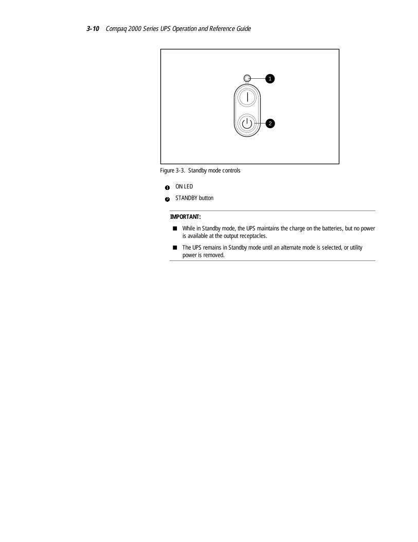
Figure 3-3. Standby mode controls
1 ON LED
2 STANDBY button
IMPORTANT:
■ While in Standby mode, the UPS maintains the charge on the batteries, but no poweris available at the output receptacles.
■ The UPS remains in Standby mode until an alternate mode is selected, or utilitypower is removed.

Operation 3-11
Initiating a Self-test
To initiate a self-test, press the TEST/ALARM RESET button (1) and holdfor three seconds. The UPS acknowledges compliance with five beeps.
1
Figure 3-4. TEST/ALARM RESET button
1 TEST/ALARM RESET button
IMPORTANT: A portion of the self-test requires battery power; the self-test cannot beinitiated if the batteries are less than 90% charged.
During the self-test, it is normal for the UPS to turn on individual LEDsmomentarily; however, if an alarm condition is detected, the UPS will turn onthe appropriate red LED and may sound an audio alarm.
WARNING: To reduce the risk of electric shock from earth conductor leakagecurrent, use the self-test procedure to check the UPS batteries (rather thanunplugging the UPS).
■ For the meaning of individual LEDs, see “Front Panel LEDs in theStandby and Operate Modes,” in this chapter.
■ For information on what to do if the self-test detects a problem, seeChapter 6, “Troubleshooting.”

3-12 Compaq 2000 Series UPS Operation and Reference Guide
Audio AlarmThe UPS may sound an audio alarm to warn the user that an alarm conditionexists.
IMPORTANT: Certain audio alarms can be disabled. See Chapter 4, “Configuration,” formore information.
Table 3-8Audio Alarm Conditions
Alarm Condition LED Activity Can be disabled?
Utility power failure LED 1 or LED 4 red Yes
Site Wiring Fault LED 5 on red Yes
Battery Service LED 10 on red Yes
Internal UPS overvoltage LED 10 flashing red No

Operation 3-13
Silencing an Audio Alarm
To silence an audio alarm, press the TEST/ALARM RESET button.
1
Figure 3-5. TEST/ALARM RESET button
1 TEST/ALARM RESET button
IMPORTANT:
■ Even though an audio alarm may be silenced, the condition that caused the alarmmay still exist. For information on procedures to follow if the UPS detects an alarmcondition, see Chapter 6, “Troubleshooting.”
■ If a utility power failure caused the alarm (AC Input LED 1 or LED 4 red), the alarmwill be silenced after utility power is restored.

Chapter 4Configuration
This chapter contains information on the following topics:
■ Placing the UPS in Configure mode
■ Configuration parameters and their LED indicators
■ Using the front panel LED display and controls to monitor and changeconfiguration parameters
■ Using the UPS configuration parameters to optimize battery life bymatching utility voltage

4-2 Compaq 2000 Series UPS Operation and Reference Guide
Placing the UPS in Configure ModeThe Compaq 2000 Series UPS models can enter the Configure mode while inthe Operate or Standby mode.
2
3
4
1
Figure 4-1. Configure mode controls
1 ON LED (LED 16)
2 ON button
3 STANDBY button
4 TEST/ALARM RESET button
To place the UPS in Configure mode, press the ON (2) and TEST/ALARM
RESET (4) buttons simultaneously. Release the buttons when theacknowledgement beep sounds.
IMPORTANT: If the STANDBY button is pressed while in the Configure mode, the UPS willenter Standby mode, and power to the load segments will cease.
In the Configure mode, the front panel LED display changes function. TheLED display and button controls allow the user to monitor, and to change, theUPS configuration parameters.

Configuration 4-3
Configuration Parametersand their LED Indicators
In the Configure mode, the front panel LEDs 1 to 15 are assigned to elevenconfiguration parameters1, detailed in the following table. (LED 16 indicatesthe ON or OFF status of each parameter.)
1
2
3
4
5
6
7
8
9
10
11
12
13
14
15
16
17
18
19
Figure 4-2. The front panel LED display and controls
1 Configuration parameters 11 to 14 are reserved for future use.
4-4 Compaq 2000 Series UPS Operation and Reference Guide
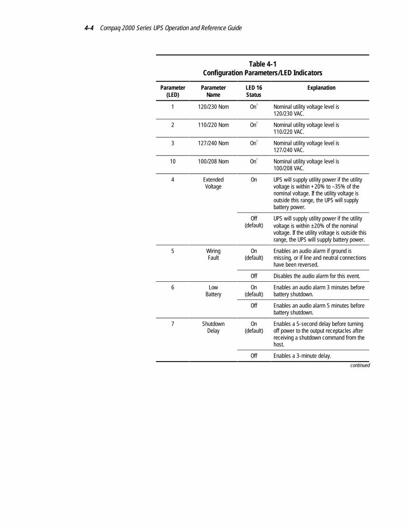
Table 4-1Configuration Parameters/LED Indicators
Parameter(LED)
ParameterName
LED 16Status
Explanation
1 120/230 Nom On1 Nominal utility voltage level is120/230 VAC.
2 110/220 Nom On1 Nominal utility voltage level is110/220 VAC.
3 127/240 Nom On1 Nominal utility voltage level is127/240 VAC.
10 100/208 Nom On1 Nominal utility voltage level is100/208 VAC.
4 ExtendedVoltage
On UPS will supply utility power if the utilityvoltage is within +20% to –35% of thenominal voltage. If the utility voltage isoutside this range, the UPS will supplybattery power.
Off(default)
UPS will supply utility power if the utilityvoltage is within ±20% of the nominalvoltage. If the utility voltage is outside thisrange, the UPS will supply battery power.
5 WiringFault
On(default)
Enables an audio alarm if ground ismissing, or if line and neutral connectionshave been reversed.
Off Disables the audio alarm for this event.
6 LowBattery
On(default)
Enables an audio alarm 3 minutes beforebattery shutdown.
Off Enables an audio alarm 5 minutes beforebattery shutdown.
7 ShutdownDelay
On(default)
Enables a 5-second delay before turningoff power to the output receptacles afterreceiving a shutdown command from thehost.
Off Enables a 3-minute delay.
continued

Configuration 4-5
Table 4-1Configuration Parameters/LED Indicators continued
Parameter(LED)
ParameterName
LED 16Status
Explanation
8 AC Input Failure On(default)
Enables an audio alarm when the utilityvoltage is outside the UPS operating range.
Off Disables the audio alarm for this event.
9 Sleep Mode On Enables Sleep mode.
Off(default)
Disables Sleep mode.
11-14 Reserved Reserved for future use.
15 Reset Defaults On Defaults are restored2.
Off Configuration selected by the useroverrides defaults.
Notes: 1 Only one nominal utility voltage can be configured.2 If model T2000j voltage defaults to 120, change the voltage to 100.
If model T2000h-NA voltage defaults to 230, change the voltage to 208.

4-6 Compaq 2000 Series UPS Operation and Reference Guide
Changing Configuration ParametersThe Configure mode can be entered from the Operate or Standby mode.
IMPORTANT: If the STANDBY button is pressed while in the Configure mode, the UPS willenter Standby mode, and power to the load segments will cease.
2
3
4
1
Figure 4-3. Configure mode controls
1 ON LED (LED 16)
2 ON button
3 STANDBY button
4 TEST/ALARM RESET button
To change configuration parameters:
1. Place the UPS in Configure mode by pressing the ON (2) and
TEST/ALARM RESET (4) buttons simultaneously. Release the buttonswhen the acknowledgement beep sounds.
2. The top left LED on the front panel LED display should begin to blink,indicating that configuration parameter 1 is selected.
3. To determine if the selected configuration parameter value is ON or
OFF, check LED 16 (1)—if LED 16 is ON, the selected parameter isalso ON.
4. To toggle the selected configuration parameter value, press the
TEST/ALARM RESET button (4). The UPS will acknowledgecompliance with a short beep.

Configuration 4-7
NOTE: For nominal voltage configuration parameters 1, 2, 3, and 10—selecting an ONvalue for any one parameter automatically sets the other three possibilities to OFF.
5. To scroll through the configuration parameters, press the ON button
(2). The UPS acknowledges compliance with a short beep. Monitor theLED display (see Figure 4-2; LED 1 blinks to indicate that parameter 1is selected, LED 2 blinks when parameter 2 is selected, and so on).
6. Repeat Steps 2 through 5 as required. Continue until all changes havebeen made.
7. To exit the Configure mode at any time:
q Press the ON (2) and TEST/ALARM RESET buttons (4)simultaneously, or
q after parameter 15 is accessed, press the ON (2) button.
The UPS will acknowledge compliance with a short beep.
Optimizing Battery Lifeby Matching the Utility Voltage
Optimize UPS battery life by using the configuration parameters to select thebest nominal voltage range for the UPS installation.
When utility voltage is outside the selected operating range, the UPS suppliesbattery power to the output receptacles. Maximize the UPS battery life byconfiguring the UPS so that the utility voltage is normally within the selectedoperating range.
Time
Volta
ge
Operating Range
Nominal
Utility Voltage
Upper Limit
Lower Limit

4-8 Compaq 2000 Series UPS Operation and Reference Guide
Figure 4-4. Optimal—Utility voltage fluctuating within the UPS operatingrange
Operating Range
Utility Voltage
+ 20%
- 20%
Time
Volta
ge
Nominal
Figure 4-5. Utility voltage fluctuation indicating a shift in nominal voltagerange may be necessary
Operating Range
Utility Voltage
+20%
- 20%
-35%
Time
Volta
ge
Nominal ExtendedRange
Figure 4-6. Utility voltage fluctuation indicating a possible need forextended range setting
To match the utility voltage, the UPS operating range can be modified in twoways:
■ If the utility voltage differs from the currently configured nominalvoltage, but stays within a ±20% band (see Fig 4-5), consider shiftingthe nominal voltage parameter selection to match the measured utilityvoltage range.

Configuration 4-9
■ If the utility voltage frequently varies outside the UPS operating range(see Fig 4-6), consider changing from normal to extended range(+20% to –35%). This provides more tolerance to brief utility voltagefluctuations.
To update the nominal voltage and operating range parameters:
1. Have a qualified electrician monitor utility voltage.
2. Use the following tables to identify the operating range that most closelymatches requirements:
Table 4-2Operating Ranges (VAC) - T2000 and T2000j Models
Nominal Level Normal Range Extended Range
100 80 to 120 Not applicable
110 88 to 132 72 to 132
120 96 to 144 78 to 144
127 102 to 152 83 to 155
Table 4-3Operating Ranges (VAC) - T2000h and T2000h-NA Models
Nominal Level Normal Range Extended Range
208 166 to 250 Not applicable
220 176 to 264 143 to 264
230 184 to 276 150 to 276
240 192 to 288 156 to 288
3. For nominal voltage level setting, select configuration parameters1, 2, 3, or 10 (see Table 4-1).
4. Access parameter 4 to switch from normal to extended range (seeTable 4-1).

Chapter 5Battery Maintenance
This chapter contains information on the following topics:
■ Precautions to be observed when maintaining or replacing externalbattery modules
■ Charging batteries
■ When to replace batteries
■ Pre-Failure Battery Warranty
■ Obtaining a new battery module
■ Replacing an external battery module
■ Care and storage of batteries

5-2 Compaq 2000 Series UPS Operation and Reference Guide
Precautions
WARNING: There is a risk of personal injury from the hazardous energy levelsassociated with UPS battery modules. The maintenance and replacement ofbattery modules must be carried out by qualified service personnel.
Replace the battery module with the Compaq spare designated for the UPS.Spare battery kit part numbers are:
■ T2000 models – 242713-001
■ T2400 models – 295461-001
WARNING: The UPS contains sealed lead-acid batteries. To reduce the risk offire or chemical burns take the following precautions:
■ Do not attempt to recharge batteries after removal from the UPS.
■ Do not disassemble, crush, or puncture the batteries.
■ Do not short the external contacts of the batteries.
■ Do not immerse the batteries in water.
■ Do not expose to temperatures higher than 60°C.
WARNING: To reduce the risk of personal injury from hazardous energy, takethese precautions:
■ Remove watches, rings, or other metal objects.
■ Use tools with insulated handles.
WARNING: The 2000 Series UPS models weigh between 79 and 97 lb(36 to 44 kg) when fully assembled.
T2000 and T2000j:UPS 32 lb (15 kg) Battery 47 lb (21 kg)
T2400h and T2400h-NA:UPS 34 lb (15 kg) Battery 63 lb (29 kg)
To reduce the risk of personal injury or damage to the equipment:
■ Observe local occupational health and safety requirements and guidelinesfor manual material handling.
■ Obtain adequate assistance to lift and stabilize the chassis duringinstallation or removal.
■ Remove the battery pack to reduce the overall weight of the product.

Battery Maintenance 5-3
IMPORTANT: Before handling a tower UPS, make sure that the UPS is on a flat, stablesurface.
Charging BatteriesThe Compaq 2000 Series UPS models automatically charge the batteries whenconnected to utility power. No user intervention is required while the UPS is inuse.
■ For information on charging the batteries when installing the UPS, see“Completing the Installation” in Chapter 2, “Installation.”
■ For information on keeping the batteries charged while the UPS is inextended storage, see “Care and Storage of Batteries,” in this chapter.
When to Replace BatteriesWhen the Battery Service indicator (LED 10) turns red, the external batterymodule may need to be replaced within 30 to 60 days.
NOTE: If the audio alarm parameter is enabled, the Battery Service indicator will beaccompanied by an audio alarm.
1
Figure 5-1. Battery Service indicator (LED 10)
1 Battery Service indicator (LED 10)

5-4 Compaq 2000 Series UPS Operation and Reference Guide
Verify that battery module replacement is required by initiating a UPS self-test. If LED 10 remains red, replace the battery module.
NOTE: Depending on usage and environmental conditions, the battery module should lastthree to six years.
For information on initiating a self-test, see Chapter 3, “Operation.”
Pre-Failure Battery WarrantyThe Pre-Failure Battery Warranty, standard on all Compaq UninterruptiblePower System (UPS) units, extends the advantage of a Compaq three-year,limited warranty by applying it to the battery before it actually fails.Specifically, the Pre-Failure Battery Warranty ensures that when customersreceive notification from Compaq Power Management Software that thebattery may fail, the battery is replaced free of charge under the warranty.
Compaq maintains the highest standards in the industry, as evidenced by theCompaq Pre-Failure Battery Warranty. The Pre-Failure Battery Warranty isbeneficial in at least two significant ways:
■ Reduced total cost of ownership
■ Reduced downtime
Obtaining a New Battery ModuleCompaq supplies spare external battery modules for all Compaq 2000 SeriesUPS models. Obtain a replacement module for the UPS when the BatteryService indicator (LED 10) illuminates, meaning that new batteries may berequired in 30 to 60 days.
The spare battery kit for a T2000 or T2000j is part number 242713-001.
The spare battery kit for a T2400h or T2400h-NA is part number 295461-001.
IMPORTANT: Compaq recommends that an inventory of spare battery modules not bemaintained onsite unless a procedure to keep the modules charged while in storage isimplemented.
For more information on the Battery Service LED function, see Chapter 3,“Operation.”

Battery Maintenance 5-5
Replacing an External Battery ModuleThere are two options for replacing a UPS external battery module:
■ Powering off the UPS before removing the battery module
■ In certain circumstances, hot-swapping the battery module withoutpowering off the UPS
CAUTION: While hot-swapping batteries, there is no protection in the event of autility power failure.
Step 1: Preparing the UPS
To replace batteries with the UPS Off
1. Shut down all load devices.
2. Press the STANDBY button to take UPS out of Operate mode. The ONLED extinguishes, and power to the load receptacles ceases.
3. Disconnect the UPS from utility power.
4. Wait at least 60 seconds, while the UPS internal circuitry discharges.
To replace batteries with the UPS inOperate mode (hot-swapping)
Batteries may be replaced (hot-swapped) without powering off the UPS if bothof the following conditions are met:
■ The UPS is not charging the batteries (Battery Charge LEDs 6, 7, and 8are all green, indicating that the batteries are fully charged).
NOTE: Older batteries may be fully charged but still incapable of providing adequatebackup for devices. Therefore, the battery charge LEDs can indicate the batteries are fullycharged, while the UPS diagnostics have determined that the batteries need to bereplaced.
■ The UPS is not supplying battery power to devices (AC Input LEDs 1and 4 are green, indicating that the UPS is supplying utility power).

5-6 Compaq 2000 Series UPS Operation and Reference Guide
Step 2: Removing the External Battery Module
Use this procedure to remove the external battery module:
1. Disconnect the battery cables from the UPS.
CAUTION: It is normal for a small amount of electrical arcing to occur whendisconnecting an external battery module from a UPS. To minimize the amountof arcing, remove the battery cables quickly and firmly.
BatteryModule
COMM. PORT
COMM. PORTM. PORT
Figure 5-2. Disconnecting an external battery module
2. Set the used external battery module aside to install the replacementmodule.
CAUTION: Load devices will not be protected from utility power failure until thebattery module is successfully replaced.

Battery Maintenance 5-7
Step 3: Installing a New Battery Module
Connect the battery cables from the new external battery module to the batteryreceptacle on the UPS.
CAUTION: It is normal for a small amount of electrical arcing to occur whenconnecting an external battery module to a UPS. To minimize the amount ofarcing, insert the battery cables into the receptacles on the UPS quickly andfirmly.
BatteryModule
COMM. PORT
M. PORT
Figure 5-3. Connecting an external battery module
If the installation has been successful, the green Battery Charge indicators(LEDs 6 to 8) show that the UPS is charging the batteries. This means that theinstallation is now complete.

5-8 Compaq 2000 Series UPS Operation and Reference Guide
Step 4: Testing a New Battery Module
After installing the new battery module, press the TEST/ALARM RESETbutton.
For information on running a self-test, see Chapter 3, “Operation.”
IMPORTANT: The UPS will not execute a self-test until the batteries are 90% charged.
If the installation has been successful, the green Battery Charge indicators(LEDs 6 to 8) show that the UPS is charging the batteries.
If the installation has not been successful, the Battery Service indicator(LED 10) will turn red. If this occurs, check the battery connections. If theBattery Service LED is still red, see Chapter 6, “Troubleshooting,” for moreinformation.
Step 5: Disposing of Used Battery Modules
The spare battery module kit includes the instructions and packaging requiredto return your used battery module to the appropriate location for disposal.
Do not dispose of the used battery module with general office orhousehold waste. Return the module for proper disposal toeither:
■ Compaq, authorized Compaq Partners, or their agents.
■ A recycling center that meets all local environmentalstandards.

Battery Maintenance 5-9
Care and Storage of BatteriesTo maximize battery life:
■ Minimize the amount of time the UPS is using battery power. MatchUPS configuration with the utility voltage. See Chapter 4,“Configuration,” for more information.
■ Keep the area around the UPS clean and dust-free. If the environment isvery dusty, clean the outside of the UPS regularly with a vacuumcleaner.
■ Maintain the ambient temperature at 25oC (77oF).
■ If storing a UPS for an extended period, recharge the batteries every sixmonths:
a. Connect the UPS to utility power.
b. Allow the UPS to remain in Standby mode.
c. Allow the UPS to charge the batteries for 24 hours.
d. Update the Battery Recharge Date label.

Chapter 6Troubleshooting
This chapter provides information on the following topics:
■ Troubleshooting problems that occur during UPS start
■ Troubleshooting problems that occur after UPS start
■ Repairing the UPS

6-2 Compaq 2000 Series UPS Operation and Reference Guide
Troubleshooting During StartIf problems occur when starting the Compaq 2000 Series UPS models, selectthe appropriate symptom for possible causes and actions suggested.
Table 6-1Troubleshooting Guide (UPS Start)
Symptom Possible Cause Suggested Action
UPS will notstart
No utility power Check power at the utility powerreceptacle or contact a qualifiedelectrician.
UPS power cord disconnected Connect the power cord.
UPS input circuit breaker open Press the circuit breaker buttonto reset. If the breaker tripsrepeatedly, contact anauthorized service provider.
LED 5 is red(Site WiringFault)
Utility power receptacleungrounded, or no ground wire inUPS power cord
Contact a qualified electrician tocorrect the condition.
Line and neutral wires reversed inutility power receptacle or in UPSpower cord
For units factory configured for208V, the Site Wiring Faultfunction has been disabled. Ifreconfiguring a 230V unit tooperate at 208V, the Site WiringFault function must be manuallydisabled.(high models only)
LED 10 is red(BatteryService)
Battery voltage is low because theUPS has been out-of-service for along period
Allow the UPS to charge thebatteries for 24 hours. Initiate aself-test: if LED 10 does not turnoff, replace the batteries.
The UPS was powered on with theSleep mode disabled, draining thebatteries

Troubleshooting 6-3
Troubleshooting After StartFor problems that occur after the UPS has gone through the startup self-testsequence, these suggested actions address possible causes.
Table 6-2Troubleshooting Guide (After Start)
Symptom Possible Cause Suggested Action
Audio Alarm Alarm condition exists Identify the red LED associatedwith this alarm condition. Checkthis troubleshooting guide todetermine the cause of thealarm.
LED 1 is red(Input Power)
Utility voltage is too high The utility voltage is higher thanthe UPS operating range. TheUPS switches to battery power.If this happens repeatedly,update the configuration.
Contact a qualified electrician tomake sure that utility power issuitable for the UPS.
LED 1 isflashing red
Alarm may need to be reset The utility voltage has returnedwithin the UPS operating range.Press the TEST/ALARM RESETbutton.
LED 4 is red(Input Power)
Utility voltage is too low The utility voltage is lower thanthe UPS operating range. TheUPS switches to battery power.If this happens repeatedly,update the configuration.
Contact a qualified electrician tomake sure that utility power issuitable for the UPS.
LED 4 isflashing red
Alarm may need to be reset The utility voltage has returnedwithin the UPS operating range.Press the TEST/ALARM RESETbutton.
continued

6-4 Compaq 2000 Series UPS Operation and Reference Guide
Table 6-2Troubleshooting Guide (After Start) continued
Symptom Possible Cause Suggested Action
UPSfrequentlyswitchesbetweenutility andbattery power
Utility power variations The utility voltage is frequentlyoutside the UPS operating range.Update the configuration.
Contact a qualified electrician tomake sure that utility power issuitable for the UPS.
LED 11 is red(Load Level)
Protected devices are exceedingthe UPS power rating
Remove one or more devices toreduce the power requirements.
Make sure that devices are notdefective.
LED 9 is red(BatteryCharge)
Low battery voltage If the UPS is supplying batterypower, save current work andshut down the system. Allow thebatteries to charge.
If the UPS is supplying utilitypower, no user intervention isrequired. Allow the batteries tocharge.
Insufficientwarning oflow batteries
Battery service required Allow batteries to charge for 24hours, then initiate self-test. IfLED 10 is red, replace batteries.
Shutdown Delay configurationinappropriate
Update the Shutdown Delayfrom 5-seconds to 3-minutes.
Use Compaq PowerManagement Software to specifya suitable delay.
LED 10 is red(BatteryService)
Potential battery failure detected Allow batteries to charge for 24hours, then initiate self-test. IfLED 10 is red, replace batteries.
New batteries improperlyconnected
Check connections.
continued

Troubleshooting 6-5
Table 6-2Troubleshooting Guide (After Start) continued
Symptom Possible Cause Suggested Action
LED 10 isflashing red;audio alarmcannot besilenced
Internal UPS overvoltage conditionexists
Shut down the UPS. Contact anauthorized service provider.
Repairing the UPSRepairs to the UPS must be carried out by Compaq or a Compaq AuthorizedService Provider. Other than battery replacement, there are no user-serviceableparts.

Appendix ARegulatory Compliance Notices
Federal CommunicationsCommission Notice
Part 15 of the Federal Communications Commission (FCC) Rules andRegulations has established Radio Frequency (RF) emission limits to providean interference-free radio frequency spectrum. Many electronic devices,including computers, generate RF energy incidental to their intended functionand are, therefore, covered by these rules. These rules place computers andrelated peripheral devices into two classes, A and B, depending upon theirintended installation. Class A devices are those that may reasonably beexpected to be installed in a business or commercial environment. Class Bdevices are those that may reasonably be expected to be installed in aresidential environment (that is, personal computers). The FCC requiresdevices in both classes to bear a label indicating the interference potential ofthe device as well as additional operating instructions for the user.
The rating label on the device shows which class (A or B) the equipment fallsinto. Class B devices have an FCC logo or FCC ID on the label. Class Adevices do not have an FCC logo or FCC ID on the label. Once the class of thedevice is determined, refer to the following corresponding statement.

A-2 Compaq 2000 Series UPS Operation and Reference Guide
Class A Equipment
This equipment has been tested and found to comply with the limits for a ClassA digital device, pursuant to Part 15 of the FCC Rules. These limits aredesigned to provide reasonable protection against harmful interference whenthe equipment is operated in a commercial environment. This equipmentgenerates, uses, and can radiate radio frequency energy and, if not installedand used in accordance with the instructions, may cause harmful interferenceto radio communications. Operation of this equipment in a residential area islikely to cause harmful interference, in which case the user will be required tocorrect the interference at personal expense.
Class B Equipment
This equipment has been tested and found to comply with the limits for a ClassB digital device, pursuant to Part 15 of the FCC Rules. These limits aredesigned to provide reasonable protection against harmful interference in aresidential installation. This equipment generates, uses, and can radiate radiofrequency energy and, if not installed and used in accordance with theinstructions, may cause harmful interference to radio communications.However, there is no guarantee that interference will not occur in a particularinstallation. If this equipment does cause harmful interference to radio ortelevision reception, which can be determined by turning the equipment offand on, the user is encouraged to try to correct the interference by one or moreof the following measures:
■ Reorient or relocate the receiving antenna.
■ Increase the separation between the equipment and receiver.
■ Connect the equipment into an outlet on a circuit different from that towhich the receiver is connected.
■ Consult the dealer or an experienced radio or television technician forhelp.

Regulatory Compliance Notices A-3
Declaration of Conformity for Products Markedwith the FCC logo - United States Only
This device complies with Part 15 of the FCC Rules. Operation is subject tothe following two conditions: (1) this device may not cause harmfulinterference, and (2) this device must accept any interference received,including interference that may cause undesired operation.
For questions regarding your product, contact:
Compaq Computer CorporationP. O. Box 692000, Mail Stop 530113Houston, Texas 77269-2000
or call 1-800-652-6672 (1-800-OK COMPAQ1). For questions regarding thisFCC declaration, contact:Compaq Computer CorporationP. O. Box 692000, Mail Stop 510101Houston, Texas 77269-2000
or call (281) 514-3333.
To identify this product, refer to the Part, Series, or Model number found onthe product.
Modifications
The FCC requires the user to be notified that any changes or modificationsmade to this device that are not expressly approved by Compaq ComputerCorporation may void the user’s authority to operate the equipment.
Cables
Connections to this device must be made with shielded cables with metallicRFI/EMI connector hoods in order to maintain compliance with FCC Rulesand Regulations.
1 For continuous quality improvement, calls may be recorded or monitored.

A-4 Compaq 2000 Series UPS Operation and Reference Guide
Canadian Notice (Avis Canadien)
Class A Equipment
This Class A digital apparatus meets all requirements of the CanadianInterference-Causing Equipment Regulations.
Cet appareil numérique de la classe A respecte toutes les exigences duRèglement sur le matériel brouilleur du Canada.
Class B Equipment
This Class B digital apparatus meets all requirements of the CanadianInterference-Causing Equipment Regulations.
Cet appareil numérique de la classe B respecte toutes les exigences duRèglement sur le matériel brouilleur du Canada.
European Union NoticeProducts with the CE Marking comply with both the EMC Directive(89/336/EEC) and the Low Voltage Directive (73/23/EEC) issued by theCommission of the European Community.
Compliance with these directives implies conformity to the followingEuropean Norms (in brackets are the equivalent international standards):
■ EN55022 (CISPR 22) - Electromagnetic Interference
■ EN50082-1 (IEC801-2, IEC801-3, IEC801-4) - ElectromagneticImmunity
■ EN60950 (IEC950) - Product Safety

Regulatory Compliance Notices A-5
Japanese NoticeJuly 14 version
Taiwanese Notice

A-6 Compaq 2000 Series UPS Operation and Reference Guide
Battery Replacement Notice Your UPS is provided with a Sealed Lead Acid battery pack. There is a dangerof explosion and risk of personal injury if the battery is incorrectly replaced ormistreated. Replacement is to be done by a Compaq authorized serviceprovider using the Compaq spare designated for this product. For moreinformation about battery replacement or proper disposal, contact yourCompaq authorized reseller or your authorized service provider.
WARNING: Your UPS contains a Sealed Lead Acid battery pack. There is risk offire and burns if the battery pack is not handled properly. To reduce the risk ofpersonal injury:
■ Do not attempt to recharge the battery.
■ Do not expose to temperatures higher than 60°C.
■ Do not disassemble, crush, puncture, short external contacts, or dispose ofin fire or water.
■ Replace only with the Compaq spare designated for this product.
Batteries, battery packs, and accumulators should not be
disposed of together with the general household waste. In order
to forward them to recycling or proper disposal, please use the
public collection system or return them to Compaq, your
authorized Compaq Partners, or their agents.

Appendix BElectrostatic Discharge
To prevent damaging the system, be aware of the precautions you need tofollow when setting up the system or handling parts. A discharge of staticelectricity from a finger or other conductor may damage system boards orother static-sensitive devices. This type of damage may reduce the lifeexpectancy of the device.
To prevent electrostatic damage, observe the following precautions:
■ Avoid hand contact by transporting and storing products in static-safecontainers.
■ Keep electrostatic-sensitive parts in their containers until they arrive atstatic-free workstations.
■ Place parts on a grounded surface before removing them from theircontainers.
■ Avoid touching pins, leads, or circuitry.
■ Always be properly grounded when touching a static-sensitivecomponent or assembly.

B-2 Compaq 2000 Series UPS Operation and Reference Guide
Grounding MethodsThere are several methods for grounding. Use one or more of the followingmethods when handling or installing electrostatic-sensitive parts:
■ Use a wrist strap connected by a ground cord to a grounded workstationor computer chassis. Wrist straps are flexible straps with a minimum of1 megohm ±10 percent resistance in the ground cords. To provideproper ground, wear the strap snug against the skin.
■ Use heel straps, toe straps, or boot straps at standing workstations. Wearthe straps on both feet when standing on conductive floors or dissipatingfloor mats.
■ Use conductive field service tools.
■ Use a portable field service kit with a folding static-dissipating workmat.
If you do not have any of the suggested equipment for proper grounding, havea Compaq authorized reseller install the part.
NOTE: For more information on static electricity, or assistance with product installation,contact your Compaq authorized reseller.

Appendix CSpecifications
This appendix provides specifications that apply to Compaq 2000 Series UPSmodels:
■ Physical specifications
■ Input specifications
■ Output specifications
■ Overcurrent protection
■ Battery specifications
■ Battery runtime
■ Environmental specifications

C-2 Compaq 2000 Series UPS Operation and Reference Guide
Physical Specifications
Table C-1Physical Specifications - Models T2000 and T2000j
Device Feature U.S. Metric
UPS Dimensions Width 7.0 in 178 mm
Height 8.8 in 224 mm
Depth 17.1 in 444 mm
Weight 32 lb 15 kg
External Battery Module Dimensions Width 7.0 in 178 mm
Height 8.8 in 224 mm
Depth 17.1 in 444 mm
Weight 47 lb 21 kg
Table C-2Physical Specifications - Models T2400h and T2400h-NA
Device Feature U.S. Metric
UPS Dimensions Width 7.0 in 178 mm
Height 8.8 in 224 mm
Depth 17.1 in 444 mm
Weight 34 lb 15 kg
External Battery Module Dimensions Width 7.0 in 178 mm
Height 8.8 in 224 mm
Depth 17.1 in 444 mm
Weight 63 lb 29 kg

Specifications C-3
Input Specifications
Table C-3Input Specifications – Per Model
UPS Model Utility VoltageFrequency (Hz)
Nominal UtilityVoltage (VAC)
Power Cord Supplied
T2000 50 100, 110 Non-detachable cord with 5-20p plug
60 100, 110120, 127
T2000j 50 100, 110 Non-detachable cord with 5-20p plug
60 100, 110120, 127
T2400h 50/60 208, 220230, 240
Detachable cord with country-specific plug
T2400h-NA 50/60 208, 220230, 240
Detachable cord with 6-15p plug

C-4 Compaq 2000 Series UPS Operation and Reference Guide
Output Specifications
Table C-4Output Specifications – Per Model
UPS Model Nominal PowerRating (VA)
Load Segment # Output Receptacles
T2000 1920 1 3 x 5-15R
2 3 x 5-15R
3 2 x 5-15R
T2000j 1920 1 3 x 5-15R
2 3 x 5-15R
3 2 x 5-15R
T2400h 2300 1 3 x IEC-320
2 3 x IEC-320
3 3 x IEC-320
T2400h-NA 2300 1 3 x IEC-320
2 3 x IEC-320
3 3 x IEC-320

Specifications C-5
Table C-5Output Specifications – 2000 Series UPS Models
Characteristics Utility Voltage (VAC) Nominal Output Voltage (VAC)
Voltage 100 102
110 to 127 115
208 204
220 to 240 230
Source of Power Regulation
Output Utility power(normal range)
±8% of nominal output voltage rating(within the guidelines of the ComputerBusiness Equipment ManufacturersAssociation)
Utility power(extended range)
+10% to -15% of nominal output voltagerating (within the guidelines of theComputer Business EquipmentManufacturers Association)
Battery power ±5% of nominal output voltage rating
Feature Specification
Other features On-line efficiency 96%
Voltage wave shape Sine wave; less than 3% distortion withlinear load
Surge suppression High energy 6500A peak
Noise filtering MOVs and line filter for normal andcommon mode use

C-6 Compaq 2000 Series UPS Operation and Reference Guide
Overcurrent Protection
Table C-6Overcurrent Protection – Per Model
UPS Model Input Protection
T2000 Circuit breakers for each load segment
T2000j Circuit breakers for each load segment
T2400h Input circuit breakerNo protection for load segments
T2400h-NA Input circuit breakerNo protection for load segments
Battery Specifications
Table C-7Battery Specifications – 2000 Series UPS Models
Feature Specification
Type Sealed lead-acid; maintenance-free
Voltage External module - 24 VDC
Charging 3 to 8 hours to full charge
Less than 3 hours to 90% capacity at default nominalutility voltage and no load

Specifications C-7
Battery Runtime
Table C-8Estimated Battery Runtime (Minutes)
Load (VA) 2000 Models 2400 Models
450 58 108
500 51 97
600 36 81
700 30 62
800 26 54
900 23 48
1000 20 43
1200 14 36
1400 12 24
1500 10 23
1800 8 19
2000 7 16
2200 14
2400 13
If a device list the power in Watts, use the following conversion equation:Volts x Amps = VA per device
If only Watts are given:Watts x 1.35 = VAVA/1000 = KVA

C-8 Compaq 2000 Series UPS Operation and Reference Guide
Environmental Specifications
Table C-9Environmental Specifications – 2000 Series UPS Models
Feature Specification
Operating temperature 0o to 40oC (32o to 104oF)
UL-tested at 25oC (77oF)
Relative humidity 0% to 95%; non-condensing
Operating altitude Up to 3000 m (10,000 ft) above sea level
Audible noise Less than 45 dBA

Index
Numbers and Symbols2000 Series UPS See
Uninterruptible Power System2000 Series
AAC Input Failure
disabling audio alarm 4-5enabling audio alarm 4-5
AC Input LEDsexplained 3-5meaning when UPS powered
up 2-10troubleshooting alarm
conditions 6-3alarm See audio alarmaudio alarm
ability to disable 3-12conditions causing an
alarm 3-12features 3-12how to respond 6-3silencing 3-3, 3-13
after utility power restored 3-13requirement to address alarm
condition 3-13
Bbatteries
changing See also replacingbattery moduleprocedures 5-5warning on weight 5-2warning to use qualified service
personnel ixwarning to use qualified service
personnel 5-2warnings on risk of fire or
burns 5-2warnings on risk of personal
injury 5-2when to change 5-3
charging 5-3, 5-9maintaining
care and storage 5-9warning on weight 5-2warning to use qualified service
personnel ixwarning to use qualified service
personnel 5-2warnings on risk of fire or
burns 5-2warnings on risk of personal
injury 5-2

2 Compaq 2000 Series UPS Operation and Reference Guide
newrecommendation against keeping
spares 5-4when to obtain 5-4
recharge date See BatteryRecharge Date label
runtime specifications C-8spare part number 5-2, 5-4specifications C-7testing 5-8
Battery Charge LEDsdisplay explained 2-10explained 3-6troubleshooting alarm
condition 6-4battery module See external
battery modulereplacing See replacing
battery moduleBattery Recharge Date label
checking the battery rechargedate, illustrated 2-6
where to find the label 2-6Battery Service LED
explained 3-6troubleshooting alarm
conditions 6-2, 6-4
CCanadian Notice (Avis
Canadien) A-3care and storage of batteries 5-9
ambient temperature 5-9charging stored batteries 5-9preventive maintenance 5-9
CE Marking A-4changing batteries 5-1changing the UPS
configuration 4-2, 4-6charging the batteries
in storage 5-9Comm port See communications
port
Communication LED,explained 3-7
communications portcaution on cable use 1-7connecting to the host
computer 2-4caution against using older
communications cables 2-4illustrated 2-5
features 1-7overview 1-7
Compaq 2000 Series UPS SeeUninterruptible Power System2000 Series
Compaq authorized reseller xiCompaq Multi-Server UPS
Card See option cardCompaq OnliNet Centro
example of use 1-9overview 1-7
Compaq Power ManagementSoftwarecapabilities 1-7example of shutdown
sequence 1-8installation requirements 2-2integration with Compaq
Insight Manager 1-7overview 1-7using a Compaq Multi-Server
UPS Card 1-8using a Compaq Scalable UPS
Card 1-9Compaq Scalable UPS Card See
option cardCompaq SNMP-EN Internal
Adapter See option cardCompaq website xicompleting the installation
charging batteries 2-10placing the UPS in Operate
mode 2-10configuration
AC Input Failure

Index 3
disabling audio alarm 4-5enabling audio alarm 4-5
changing 4-6Low Battery
configuration parametersexplained 4-4
specifying audio alarm 4-4nominal utility voltage level
related configurationparameters 4-4
nominal utility voltage rangerelated configuration
parameters 4-4overview 4-1parameters 4-3Reset Defaults, restoring 4-5Shutdown Delay
enabling 3-minute 4-4enabling 5-second 4-4
Sleep modedisabling 4-5enabling 4-5
warning about pressingSTANDBY 4-2, 4-6
Wiring Fault audio alarmdisabling 4-4enabling 4-4
Configure modeexiting 4-7explained 3-2initiating 3-3
connectingbattery cables 2-3devices to UPS 2-7external battery module 2-3Network Transient
Protector 2-5UPS to utility power 2-7UPS/computer interface
cable 2-4controls and indicators See front
panel, indicatorsconverting Watts to VA 2-7
DDeclaration of Conformity A-2disposing of used battery
module 5-8
Eenvironmental specifications C-9European Union Notice A-4external battery module
care and storage ofbatteries 5-9
caution concerning arcing 2-3disconnecting, illustrated 5-6disposing of used module 5-8features 2-3installing 2-3installing, illustrated 2-4removing 5-6testing new module 5-8
FFailSafe III
overview 1-7requirement for cabling to host
computer 2-4features
Compaq 2000 Series UPS 1-6battery maintenance 5-1communications port 1-7Compaq Multi-Server UPS
Card 1-8Compaq OnliNet Centro 1-7Compaq Power Management
Software 1-7Compaq Scalable UPS Card 1-9Compaq SNMP-EN Internal
Adapter 1-9FailSafe III 1-7LanSafe III 1-7Network Transient
Protector 1-10

4 Compaq 2000 Series UPS Operation and Reference Guide
warranties 1-10Federal Communications
Commission (FCC) notice A-1cables A-3FCC Class A compliance A-2FCC Class B compliance A-2modifications to
equipment A-3front panel
AC Input LEDs,explained 3-5
Battery Charge LEDs,explained 3-6
Battery Service LED,explained 3-6
Communication LED,explained 3-7
illustrated 1-3indicating battery charge 5-7,
5-8indicators 3-5LED display and controls,
illustrated 2-9Load Level LEDs,
explained 3-7meaning of LED display in
Configure mode 4-6meaning of LED display in
Standby and Operatemodes 3-5
ON LED, explained 3-7reading the LED display 3-5Site Wiring Fault LED,
explained 3-6
Ggetting help xGrounding Methods B-2guarantee See warranties
Hhardware option card See option
cardhelp
additional sources xCompaq authorized
resellers xiCompaq website xitechnical support telephone
numbers x
hot-swapping See replacing batterymodule
http//www.compaq.com xi
Iicons
symbols on equipment viii Important Safety Information x, 2-2,
2-3indicators See front panel,
indicatorsinput specifications C-3installing a UPS
before starting the UPS 2-3caution against using older
communicationscables 2-4
caution concerning arcing 2-3checking the load 2-7completing the
installation 2-10connecting the communications
port 2-4connecting the communications
port, illustrated 2-5connecting the devices 2-7
caution against plugging in laserprinters 2-7
warning on earth conductorleakage current 2-7

Index 5
connecting the NetworkTransient Protector 2-5
connecting the NetworkTransient Protector,illustrated 2-5
connecting to utilitypower 2-7
installing an external batterymodule 2-3
installing an external batterymodule, illustrated 2-4
requirements 2-2hardware 2-2software 2-2tools 2-2
silencing the audio alarm 2-10starting the UPS
checking the Battery RechargeDate label 2-6
checking the battery rechargedate, illustrated 2-6
for the first time 2-6warning concerning
grounding 2-7warning concerning red
LEDs 2-10
JJapanese Notice A-5
LLanSafe III
overview 1-7requirement for cabling to host
computer 2-4LED 01 See AC Input LEDsLED 02 See AC Input LEDsLED 03 See AC Input LEDsLED 04 See AC Input LEDsLED 05 See Site Wiring Fault
LEDLED 06 See Battery Charge LEDs
LED 07 See Battery Charge LEDsLED 08 See Battery Charge LEDsLED 09 See Battery Charge LEDsLED 10 See Battery Service LEDLED 11 See Load Level LEDsLED 12 See Load Level LEDsLED 13 See Load Level LEDsLED 14 See Load Level LEDsLED 15 See Communication LEDLED 16 See ON LEDLED display See front panel,
indicatorsLoad Level LEDs
explained 3-7troubleshooting alarm
condition 6-4Low Battery
configuraton parametersexplained 4-4
specifying audio alarm 4-4
Mmaintenance, battery 5-9matching, utility voltage with UPS
configuration 4-7modes of operation See Standby
mode, Operate mode, Configuremode, Sleep mode
modifications to equipment SeeFederal CommunicationsCommission (FCC) notice
NNetwork Transient Protector
connecting 2-5connecting, illustrated 2-5features 1-10not connecting to a digital
PBX 2-5overview 1-10
nominal utility voltage level

6 Compaq 2000 Series UPS Operation and Reference Guide
explained 4-4related configuration
parameters 4-4nominal utility voltage range
explained 4-4related configuration
parameters 4-4
OON button
exiting Configure mode 4-7initiating Configure mode 4-2,
4-6selecting configuration
parameters 4-7ON LED
explained 3-7indicating Operate mode 2-10meaning when UPS powered
up 2-10Operate mode
explained 3-2initiating 2-10, 3-3, 3-8
conserving battery power 3-8LED display 3-8
operating rangeconfiguring 4-7matching 4-7matching the utility
voltage 4-9supplying battery power 4-7tabulated for all
configurations 4-10operating the UPS
modes of operation 3-2warning on earth conductor
leakage current 3-2option card
Compaq Multi-Server UPSCardexample of use 1-8overview 1-8
Compaq Scalable UPS Card
example of use 1-9overview 1-9
Compaq SNMP-EN InternalAdapterexample of use 1-9overview 1-9
overview 1-8protecting multiple
servers 1-8scaling up UPS
capabilities 1-9output specifications C-4overcurrent protection 3-8overview
battery maintenance 5-1communications port 1-7Compaq Multi-Server UPS
Card 1-8Compaq OnliNet Centro 1-7Compaq Power Management
Software 1-7Compaq Scalable UPS
Card 1-9Compaq SNMP-EN Internal
Adapter 1-9FailSafe III 1-7installation 2-1LanSafe III 1-7Network Transient
Protector 1-10operating the UPS 3-1option card 1-8specifications C-1troubleshooting 6-1UPS 1-1
PPBX, caution on connecting to
Network TransientProtector 1-10
physical specifications C-2T2000 and T2000j C-2T2400h and T2400h-NA C-2

Index 7
power cordcords shipped with the
UPS 2-2requirement for additional
cord 2-3solution for additional
cord 2-3Power Management Software See
Compaq Power ManagementSoftware
Power Products Documentation CDviewing
Compaq 2000 Series UPSOperation and ReferenceGuide 2-2
Compaq Power ProductsSoftware ReferenceGuide 2-2
powering the UPS off SeeSTANDBY button
problems See troubleshooting
Rrange See operating rangerear panels, illustrated 1-4recharge date See Battery
Recharge Date labelreference material
Compaq Power ManagementSoftware InstallationInstructions 2-2
Compaq Power ProductsSoftware ReferenceGuide 2-2
Important Safety Information x, 2-2, 2-3
repairing the UPS 6-5replacing battery module
conditions forhot-swapping 5-5
connecting external batterymodule, illustrated 5-7
disposing of used module 5-8
installing new batterymodule 5-7
options 5-5procedure 5-5removing the external battery
module 5-6testing new module 5-8when to replace 5-3with the UPS in Operate
mode 5-5with the UPS off 5-5
Reset Defaults, restoring 4-5RJ-45 receptacle ixRS-232 port See communications
port
Ssafety precautions
battery handling ixearth conductor leakage
current ix Important Safety Information x,
2-2, 2-3weight xwhen using the UPS 3-2
self-testinitiating See TEST/ALARM
RESET buttonmeaning of LED display 3-11
serial port See communicationsport
Shutdown Delay, selecting 4-4shutdown sequence
specifying 1-8Site Wiring Fault LED
explained 3-6function disabled for 208V
congiuration 6-2troubleshooting alarm
condition 6-2Sleep mode
disabling 4-5enabling 4-5

8 Compaq 2000 Series UPS Operation and Reference Guide
explained 3-3specifications
battery C-7battery runtime C-8environmental C-9input C-3output C-4overcurrent protection C-6overview C-1physical C-2
STANDBY buttonpowering the UPS off 3-9, 5-5warning concerning use in
Configure mode 4-2, 4-6Standby mode
automatically maintainingbattery charge 3-10
exiting from 3-10explained 3-2initiating 3-3returning to, from Operate
mode 3-9starting the UPS for the first
time 2-6switching the UPS off See
STANDBY buttonsymbols in text viiisymbols on equipment viiisystem administrator
specifying the shutdownsequence 1-8
using Compaq PowerManagement Software 1-7
Ttechnical support xtelephone numbers xiTEST/ALARM RESET button
exiting Configure mode 4-7initiating a self-test 3-11initiating Configure mode 4-2,
4-6
testing new batterymodule 5-8
toggling a configurationparameter 4-6
testinginitiating a self-test 3-11new battery modules 5-8
text conventions viitroubleshooting
after start 6-3during start 6-2
UUninterruptible Power System 2000
Seriesconnecting UPS/computer
interface cable 2-4features 1-6front panel 1-3front panel,illustrated 1-3items not supplied with the
UPS kit 2-2items supplied with the UPS
kit 2-2models 1-2rear panels 1-4
updating the UPSconfiguration 4-2, 4-6
utility voltageconfiguring the UPS to
match 4-9matching with UPS
configuration 4-7monitored by qualified
electrician 4-9utility voltage range See operating
range

Index 9
VVCCI Notice for Japan A-5voltage level, nominal,
configuring 4-4voltage range, nominal,
configuring 4-4
Wwarning
battery handling ixelectrical shock ixhigh earth conductor leakage
current ixweight x
warranties$25,000 Computer Load
Protection Guarantee 1-10applicability 1-10limited warranty 1-10pre-failure battery 1-10, 5-4qualifying 1-10three-year limited 1-10
Wiring Faultaudio alarm disable 4-4audio alarm enable 4-4
www.compaq.com x