
UPS Catalouge
80
AC Power For Business-Critical Continuity Liebert NX ™ UPS Installation Manual–10-30kVA, 208V, 60Hz
-
Upload
engr-falak -
Category
Documents
-
view
62 -
download
2
description
UPS
Transcript of UPS Catalouge
AC PowerFor Business-Critical Continuity
Liebert NX™ UPSInstallation Manual–10-30kVA, 208V, 60Hz

i
TABLE OF CONTENTSIMPORTANT SAFETY INSTRUCTIONS . . . . . . . . . . . . . . . . . . . . . . . . . . . . . . . . . . . . . . . . . . . . . . . .1GLOSSARY OF SYMBOLS. . . . . . . . . . . . . . . . . . . . . . . . . . . . . . . . . . . . . . . . . . . . . . . . . . . . . . . .31.0 INSTALLATION . . . . . . . . . . . . . . . . . . . . . . . . . . . . . . . . . . . . . . . . . . . . . . . . . . . . . . . . . .41.1 External Inspections . . . . . . . . . . . . . . . . . . . . . . . . . . . . . . . . . . . . . . . . . . . . . . . . . . . . . . . . . 41.2 Internal Inspections . . . . . . . . . . . . . . . . . . . . . . . . . . . . . . . . . . . . . . . . . . . . . . . . . . . . . . . . . . 4
1.2.1 Storing for Delayed Installation . . . . . . . . . . . . . . . . . . . . . . . . . . . . . . . . . . . . . . . . . . . . . . . . . 5
1.3 Preliminary Checks . . . . . . . . . . . . . . . . . . . . . . . . . . . . . . . . . . . . . . . . . . . . . . . . . . . . . . . . . . 51.3.1 Identification. . . . . . . . . . . . . . . . . . . . . . . . . . . . . . . . . . . . . . . . . . . . . . . . . . . . . . . . . . . . . . . . . 5
1.4 UPS Location . . . . . . . . . . . . . . . . . . . . . . . . . . . . . . . . . . . . . . . . . . . . . . . . . . . . . . . . . . . . . . . 51.4.1 Positioning the UPS . . . . . . . . . . . . . . . . . . . . . . . . . . . . . . . . . . . . . . . . . . . . . . . . . . . . . . . . . . . 51.4.2 Environmental Considerations . . . . . . . . . . . . . . . . . . . . . . . . . . . . . . . . . . . . . . . . . . . . . . . . . . 51.4.3 Special Considerations for 1+N Systems . . . . . . . . . . . . . . . . . . . . . . . . . . . . . . . . . . . . . . . . . . 6
1.5 Considerations in Moving the NX . . . . . . . . . . . . . . . . . . . . . . . . . . . . . . . . . . . . . . . . . . . . . . . 61.6 Mechanical Considerations . . . . . . . . . . . . . . . . . . . . . . . . . . . . . . . . . . . . . . . . . . . . . . . . . . . . 6
1.6.1 Clearances. . . . . . . . . . . . . . . . . . . . . . . . . . . . . . . . . . . . . . . . . . . . . . . . . . . . . . . . . . . . . . . . . . . 71.6.2 Floor Installation . . . . . . . . . . . . . . . . . . . . . . . . . . . . . . . . . . . . . . . . . . . . . . . . . . . . . . . . . . . . . 71.6.3 Cable Entry. . . . . . . . . . . . . . . . . . . . . . . . . . . . . . . . . . . . . . . . . . . . . . . . . . . . . . . . . . . . . . . . . . 71.6.4 Optional Cabinets. . . . . . . . . . . . . . . . . . . . . . . . . . . . . . . . . . . . . . . . . . . . . . . . . . . . . . . . . . . . . 8
2.0 ELECTRICAL CONNECTIONS . . . . . . . . . . . . . . . . . . . . . . . . . . . . . . . . . . . . . . . . . . . . . . . .92.1 Power Cabling. . . . . . . . . . . . . . . . . . . . . . . . . . . . . . . . . . . . . . . . . . . . . . . . . . . . . . . . . . . . . . . 9
2.1.1 Cable Rating . . . . . . . . . . . . . . . . . . . . . . . . . . . . . . . . . . . . . . . . . . . . . . . . . . . . . . . . . . . . . . . . . 92.1.2 UPS Input Configuration . . . . . . . . . . . . . . . . . . . . . . . . . . . . . . . . . . . . . . . . . . . . . . . . . . . . . . 102.1.3 Cabling Guidelines . . . . . . . . . . . . . . . . . . . . . . . . . . . . . . . . . . . . . . . . . . . . . . . . . . . . . . . . . . . 102.1.4 Cable Connections . . . . . . . . . . . . . . . . . . . . . . . . . . . . . . . . . . . . . . . . . . . . . . . . . . . . . . . . . . . 112.1.5 Safety Ground. . . . . . . . . . . . . . . . . . . . . . . . . . . . . . . . . . . . . . . . . . . . . . . . . . . . . . . . . . . . . . . 122.1.6 Protective Devices. . . . . . . . . . . . . . . . . . . . . . . . . . . . . . . . . . . . . . . . . . . . . . . . . . . . . . . . . . . . 122.1.7 Cabling Procedure . . . . . . . . . . . . . . . . . . . . . . . . . . . . . . . . . . . . . . . . . . . . . . . . . . . . . . . . . . . 13
2.2 Control Cables . . . . . . . . . . . . . . . . . . . . . . . . . . . . . . . . . . . . . . . . . . . . . . . . . . . . . . . . . . . . . 142.2.1 Monitor Board Features . . . . . . . . . . . . . . . . . . . . . . . . . . . . . . . . . . . . . . . . . . . . . . . . . . . . . . . 14
2.3 Dry Contacts . . . . . . . . . . . . . . . . . . . . . . . . . . . . . . . . . . . . . . . . . . . . . . . . . . . . . . . . . . . . . . . 152.3.1 Input Dry Contacts. . . . . . . . . . . . . . . . . . . . . . . . . . . . . . . . . . . . . . . . . . . . . . . . . . . . . . . . . . . 152.3.2 Maintenance Bypass Cabinet Interface . . . . . . . . . . . . . . . . . . . . . . . . . . . . . . . . . . . . . . . . . . 162.3.3 BCB Box Interface . . . . . . . . . . . . . . . . . . . . . . . . . . . . . . . . . . . . . . . . . . . . . . . . . . . . . . . . . . . 162.3.4 Output Dry Contacts . . . . . . . . . . . . . . . . . . . . . . . . . . . . . . . . . . . . . . . . . . . . . . . . . . . . . . . . . 172.3.5 EPO Input—Optional . . . . . . . . . . . . . . . . . . . . . . . . . . . . . . . . . . . . . . . . . . . . . . . . . . . . . . . . . 17
3.0 BATTERY INSTALLATION . . . . . . . . . . . . . . . . . . . . . . . . . . . . . . . . . . . . . . . . . . . . . . . . . .193.1 Introduction . . . . . . . . . . . . . . . . . . . . . . . . . . . . . . . . . . . . . . . . . . . . . . . . . . . . . . . . . . . . . . . 193.2 Safety . . . . . . . . . . . . . . . . . . . . . . . . . . . . . . . . . . . . . . . . . . . . . . . . . . . . . . . . . . . . . . . . . . . . 193.3 UPS Batteries . . . . . . . . . . . . . . . . . . . . . . . . . . . . . . . . . . . . . . . . . . . . . . . . . . . . . . . . . . . . . . 19

ii
3.4 External Battery Cabinet Installation . . . . . . . . . . . . . . . . . . . . . . . . . . . . . . . . . . . . . . . . . . 203.4.1 Matching Battery Cabinets . . . . . . . . . . . . . . . . . . . . . . . . . . . . . . . . . . . . . . . . . . . . . . . . . . . . 203.4.2 Connecting the Batteries . . . . . . . . . . . . . . . . . . . . . . . . . . . . . . . . . . . . . . . . . . . . . . . . . . . . . . 203.4.3 Installation Considerations . . . . . . . . . . . . . . . . . . . . . . . . . . . . . . . . . . . . . . . . . . . . . . . . . . . . 223.4.4 Connecting the Battery Cabinet to the UPS. . . . . . . . . . . . . . . . . . . . . . . . . . . . . . . . . . . . . . . 24
3.5 Non-Standard Batteries . . . . . . . . . . . . . . . . . . . . . . . . . . . . . . . . . . . . . . . . . . . . . . . . . . . . . . 24
4.0 MAINTENANCE BYPASS CABINET . . . . . . . . . . . . . . . . . . . . . . . . . . . . . . . . . . . . . . . . . . .254.1 Bypass Switch. . . . . . . . . . . . . . . . . . . . . . . . . . . . . . . . . . . . . . . . . . . . . . . . . . . . . . . . . . . . . . 254.2 Normal (UPS) Mode . . . . . . . . . . . . . . . . . . . . . . . . . . . . . . . . . . . . . . . . . . . . . . . . . . . . . . . . . 254.3 Bypass Mode . . . . . . . . . . . . . . . . . . . . . . . . . . . . . . . . . . . . . . . . . . . . . . . . . . . . . . . . . . . . . . . 264.4 Maintenance Mode . . . . . . . . . . . . . . . . . . . . . . . . . . . . . . . . . . . . . . . . . . . . . . . . . . . . . . . . . . 264.5 Locating the Cabinet . . . . . . . . . . . . . . . . . . . . . . . . . . . . . . . . . . . . . . . . . . . . . . . . . . . . . . . . 264.6 Cable Installation . . . . . . . . . . . . . . . . . . . . . . . . . . . . . . . . . . . . . . . . . . . . . . . . . . . . . . . . . . . 26
4.6.1 Wiring Preparation. . . . . . . . . . . . . . . . . . . . . . . . . . . . . . . . . . . . . . . . . . . . . . . . . . . . . . . . . . . 264.6.2 Power Cable Installation . . . . . . . . . . . . . . . . . . . . . . . . . . . . . . . . . . . . . . . . . . . . . . . . . . . . . . 274.6.3 Input/Output Wiring . . . . . . . . . . . . . . . . . . . . . . . . . . . . . . . . . . . . . . . . . . . . . . . . . . . . . . . . . 27
4.7 Bolting Cabinets Together . . . . . . . . . . . . . . . . . . . . . . . . . . . . . . . . . . . . . . . . . . . . . . . . . . . . 29
5.0 OPTIONS . . . . . . . . . . . . . . . . . . . . . . . . . . . . . . . . . . . . . . . . . . . . . . . . . . . . . . . . . . . . .305.1 Load Bus Synchronization . . . . . . . . . . . . . . . . . . . . . . . . . . . . . . . . . . . . . . . . . . . . . . . . . . . . 30
5.1.1 Performance Requirements . . . . . . . . . . . . . . . . . . . . . . . . . . . . . . . . . . . . . . . . . . . . . . . . . . . . 305.1.2 DBS Cable and Settings . . . . . . . . . . . . . . . . . . . . . . . . . . . . . . . . . . . . . . . . . . . . . . . . . . . . . . . 30
5.2 Configuring Parallel System Operation . . . . . . . . . . . . . . . . . . . . . . . . . . . . . . . . . . . . . . . . . 315.2.1 General . . . . . . . . . . . . . . . . . . . . . . . . . . . . . . . . . . . . . . . . . . . . . . . . . . . . . . . . . . . . . . . . . . . . 315.2.2 Features of Parallel System. . . . . . . . . . . . . . . . . . . . . . . . . . . . . . . . . . . . . . . . . . . . . . . . . . . . 315.2.3 Operating Principles. . . . . . . . . . . . . . . . . . . . . . . . . . . . . . . . . . . . . . . . . . . . . . . . . . . . . . . . . . 325.2.4 Operation Modes Summary . . . . . . . . . . . . . . . . . . . . . . . . . . . . . . . . . . . . . . . . . . . . . . . . . . . . 32
5.3 Installing Parallel System . . . . . . . . . . . . . . . . . . . . . . . . . . . . . . . . . . . . . . . . . . . . . . . . . . . . 325.3.1 Conditions for Parallel System . . . . . . . . . . . . . . . . . . . . . . . . . . . . . . . . . . . . . . . . . . . . . . . . . 325.3.2 Cabinet Installation . . . . . . . . . . . . . . . . . . . . . . . . . . . . . . . . . . . . . . . . . . . . . . . . . . . . . . . . . . 325.3.3 Preliminary Checks . . . . . . . . . . . . . . . . . . . . . . . . . . . . . . . . . . . . . . . . . . . . . . . . . . . . . . . . . . 325.3.4 Protective Devices. . . . . . . . . . . . . . . . . . . . . . . . . . . . . . . . . . . . . . . . . . . . . . . . . . . . . . . . . . . . 325.3.5 Power Cables. . . . . . . . . . . . . . . . . . . . . . . . . . . . . . . . . . . . . . . . . . . . . . . . . . . . . . . . . . . . . . . . 335.3.6 Parallel Control Cables . . . . . . . . . . . . . . . . . . . . . . . . . . . . . . . . . . . . . . . . . . . . . . . . . . . . . . . 335.3.7 Emergency Power Off (EPO) . . . . . . . . . . . . . . . . . . . . . . . . . . . . . . . . . . . . . . . . . . . . . . . . . . . 35
5.4 Battery Circuit Breaker Box . . . . . . . . . . . . . . . . . . . . . . . . . . . . . . . . . . . . . . . . . . . . . . . . . . 36
6.0 UPS SPECIFICATIONS. . . . . . . . . . . . . . . . . . . . . . . . . . . . . . . . . . . . . . . . . . . . . . . . . . . .386.1 Conformity and Standards. . . . . . . . . . . . . . . . . . . . . . . . . . . . . . . . . . . . . . . . . . . . . . . . . . . . 386.2 UPS Environmental . . . . . . . . . . . . . . . . . . . . . . . . . . . . . . . . . . . . . . . . . . . . . . . . . . . . . . . . . 386.3 UPS Mechanical Characteristics . . . . . . . . . . . . . . . . . . . . . . . . . . . . . . . . . . . . . . . . . . . . . . . 386.4 UPS Electrical Characteristics . . . . . . . . . . . . . . . . . . . . . . . . . . . . . . . . . . . . . . . . . . . . . . . . 39
6.4.1 Battery Manufacturers and Models . . . . . . . . . . . . . . . . . . . . . . . . . . . . . . . . . . . . . . . . . . . . . 406.4.2 Input Rectifier. . . . . . . . . . . . . . . . . . . . . . . . . . . . . . . . . . . . . . . . . . . . . . . . . . . . . . . . . . . . . . . 406.4.3 DC Intermediate Circuit . . . . . . . . . . . . . . . . . . . . . . . . . . . . . . . . . . . . . . . . . . . . . . . . . . . . . . 406.4.4 Inverter Output . . . . . . . . . . . . . . . . . . . . . . . . . . . . . . . . . . . . . . . . . . . . . . . . . . . . . . . . . . . . . 416.4.5 Bypass Input . . . . . . . . . . . . . . . . . . . . . . . . . . . . . . . . . . . . . . . . . . . . . . . . . . . . . . . . . . . . . . . . 41
iii
7.0 INSTALLATION DRAWINGS. . . . . . . . . . . . . . . . . . . . . . . . . . . . . . . . . . . . . . . . . . . . . . . . .428.0 SPECIFICATIONS AND TECHNICAL DATA. . . . . . . . . . . . . . . . . . . . . . . . . . . . . . . . . . . . . . .598.1 Lug Size and Torque Requirements . . . . . . . . . . . . . . . . . . . . . . . . . . . . . . . . . . . . . . . . . . . . 598.2 Cable Lengths: Floor to Connection Point Inside UPS . . . . . . . . . . . . . . . . . . . . . . . . . . . . . 70
FIGURESFigure 1 Cabinet arrangement . . . . . . . . . . . . . . . . . . . . . . . . . . . . . . . . . . . . . . . . . . . . . . . . . . . . . . . . . . . . . 8Figure 2 Single module block diagram—dual input configuration . . . . . . . . . . . . . . . . . . . . . . . . . . . . . . . . 10Figure 3 Input busbars . . . . . . . . . . . . . . . . . . . . . . . . . . . . . . . . . . . . . . . . . . . . . . . . . . . . . . . . . . . . . . . . . . 11Figure 4 Battery fuses and connections . . . . . . . . . . . . . . . . . . . . . . . . . . . . . . . . . . . . . . . . . . . . . . . . . . . . . 11Figure 5 Ground and neutral busbar connections . . . . . . . . . . . . . . . . . . . . . . . . . . . . . . . . . . . . . . . . . . . . . 12Figure 6 Monitor board U2 . . . . . . . . . . . . . . . . . . . . . . . . . . . . . . . . . . . . . . . . . . . . . . . . . . . . . . . . . . . . . . . 14Figure 7 Auxiliary terminal block detail (Monitoring Board) . . . . . . . . . . . . . . . . . . . . . . . . . . . . . . . . . . . . 15Figure 8 Input dry contacts . . . . . . . . . . . . . . . . . . . . . . . . . . . . . . . . . . . . . . . . . . . . . . . . . . . . . . . . . . . . . . . 15Figure 9 Jumper connection for BCB interface . . . . . . . . . . . . . . . . . . . . . . . . . . . . . . . . . . . . . . . . . . . . . . . 16Figure 10 Output dry contacts and EPO wiring for firmware before M170 . . . . . . . . . . . . . . . . . . . . . . . . . . 17Figure 11 EPO wiring for firmware M200 or later . . . . . . . . . . . . . . . . . . . . . . . . . . . . . . . . . . . . . . . . . . . . . 18Figure 12 Battery cabinet—details . . . . . . . . . . . . . . . . . . . . . . . . . . . . . . . . . . . . . . . . . . . . . . . . . . . . . . . . . . 20Figure 13 Narrow battery cabinet, 27 in. (690mm) - rear view. . . . . . . . . . . . . . . . . . . . . . . . . . . . . . . . . . . . 21Figure 14 Wide battery cabinet, 57 in. (1488mm) - front view . . . . . . . . . . . . . . . . . . . . . . . . . . . . . . . . . . . . 21Figure 15 Internal cable wiring from battery cabinet to Liebert NX . . . . . . . . . . . . . . . . . . . . . . . . . . . . . . . 23Figure 16 Battery tray and supports . . . . . . . . . . . . . . . . . . . . . . . . . . . . . . . . . . . . . . . . . . . . . . . . . . . . . . . . 23Figure 17 Single UPS with external Maintenance Bypass Cabinet—typical configuration . . . . . . . . . . . . . 25Figure 18 Maintenance Bypass Cabinet—access plate removed . . . . . . . . . . . . . . . . . . . . . . . . . . . . . . . . . . 26Figure 19 Maintenance Bypass Cabinet wiring access panel . . . . . . . . . . . . . . . . . . . . . . . . . . . . . . . . . . . . . 27Figure 20 Maintenance bypass control wire location. . . . . . . . . . . . . . . . . . . . . . . . . . . . . . . . . . . . . . . . . . . . 28Figure 21 Load Bus Synchronization cable connection . . . . . . . . . . . . . . . . . . . . . . . . . . . . . . . . . . . . . . . . . . 30Figure 22 1+N system block diagram . . . . . . . . . . . . . . . . . . . . . . . . . . . . . . . . . . . . . . . . . . . . . . . . . . . . . . . . 31Figure 23 Connecting '1+N' system parallel control cables . . . . . . . . . . . . . . . . . . . . . . . . . . . . . . . . . . . . . . . 33Figure 24 Auxiliary dry contact cables for output breaker in multi-module system . . . . . . . . . . . . . . . . . . . 34Figure 25 Dry contacts, multiple UPS modules with distribution panel . . . . . . . . . . . . . . . . . . . . . . . . . . . . 34Figure 26 Connecting EPO push button. . . . . . . . . . . . . . . . . . . . . . . . . . . . . . . . . . . . . . . . . . . . . . . . . . . . . . 35Figure 27 Battery circuit breaker box connections . . . . . . . . . . . . . . . . . . . . . . . . . . . . . . . . . . . . . . . . . . . . . 37Figure 28 Dimensional view- front and left side views . . . . . . . . . . . . . . . . . . . . . . . . . . . . . . . . . . . . . . . . . . 42Figure 29 Dimensions continued—top and bottom views . . . . . . . . . . . . . . . . . . . . . . . . . . . . . . . . . . . . . . . . 43Figure 30 Main components—typical unit . . . . . . . . . . . . . . . . . . . . . . . . . . . . . . . . . . . . . . . . . . . . . . . . . . . . 43Figure 31 Cable connections . . . . . . . . . . . . . . . . . . . . . . . . . . . . . . . . . . . . . . . . . . . . . . . . . . . . . . . . . . . . . . . 44Figure 32 Location of internal batteries . . . . . . . . . . . . . . . . . . . . . . . . . . . . . . . . . . . . . . . . . . . . . . . . . . . . . . 45Figure 33 Battery connections . . . . . . . . . . . . . . . . . . . . . . . . . . . . . . . . . . . . . . . . . . . . . . . . . . . . . . . . . . . . . 46Figure 34 Battery cabinet interconnection . . . . . . . . . . . . . . . . . . . . . . . . . . . . . . . . . . . . . . . . . . . . . . . . . . . . 47Figure 35 Maintenance Bypass interconnection . . . . . . . . . . . . . . . . . . . . . . . . . . . . . . . . . . . . . . . . . . . . . . . 48Figure 36 NX 1+1 parallel cabinet interconnections . . . . . . . . . . . . . . . . . . . . . . . . . . . . . . . . . . . . . . . . . . . . 49Figure 37 Lineup detail—SlimLine distribution cabinet to NX . . . . . . . . . . . . . . . . . . . . . . . . . . . . . . . . . . . 50Figure 38 Lineup detail—1+N Type A connection to NX . . . . . . . . . . . . . . . . . . . . . . . . . . . . . . . . . . . . . . . . 51Figure 39 Lineup detail—1+N Type A1 connection to NX . . . . . . . . . . . . . . . . . . . . . . . . . . . . . . . . . . . . . . . 52Figure 40 Lineup detail—1+N Type B connection to NX . . . . . . . . . . . . . . . . . . . . . . . . . . . . . . . . . . . . . . . . 53Figure 41 Lineup detail—1+N Type B1 connection to NX . . . . . . . . . . . . . . . . . . . . . . . . . . . . . . . . . . . . . . . 54Figure 42 Lineup detail—1+N Type C connection to NX . . . . . . . . . . . . . . . . . . . . . . . . . . . . . . . . . . . . . . . . 55Figure 43 Lineup detail—1+N Type C1 connection to NX . . . . . . . . . . . . . . . . . . . . . . . . . . . . . . . . . . . . . . . 56Figure 44 Lineup detail—1+N Type D connection to NX . . . . . . . . . . . . . . . . . . . . . . . . . . . . . . . . . . . . . . . . 57Figure 45 SlimLine locations. . . . . . . . . . . . . . . . . . . . . . . . . . . . . . . . . . . . . . . . . . . . . . . . . . . . . . . . . . . . . . . 58

iv
TABLESTable 1 Input dry contacts at X3 . . . . . . . . . . . . . . . . . . . . . . . . . . . . . . . . . . . . . . . . . . . . . . . . . . . . . . . . . . 15Table 2 Maintenance bypass cabinet interface. . . . . . . . . . . . . . . . . . . . . . . . . . . . . . . . . . . . . . . . . . . . . . . 16Table 3 BCB box interface . . . . . . . . . . . . . . . . . . . . . . . . . . . . . . . . . . . . . . . . . . . . . . . . . . . . . . . . . . . . . . . 16Table 4 Output dry contact relays. . . . . . . . . . . . . . . . . . . . . . . . . . . . . . . . . . . . . . . . . . . . . . . . . . . . . . . . . 17Table 5 EPO input contact relays . . . . . . . . . . . . . . . . . . . . . . . . . . . . . . . . . . . . . . . . . . . . . . . . . . . . . . . . . 17Table 6 EPO input contact relays . . . . . . . . . . . . . . . . . . . . . . . . . . . . . . . . . . . . . . . . . . . . . . . . . . . . . . . . . 18Table 7 Available battery circuit breaker boxes . . . . . . . . . . . . . . . . . . . . . . . . . . . . . . . . . . . . . . . . . . . . . . 36Table 8 Environmental characteristics . . . . . . . . . . . . . . . . . . . . . . . . . . . . . . . . . . . . . . . . . . . . . . . . . . . . . 38Table 9 Mechanical characteristics . . . . . . . . . . . . . . . . . . . . . . . . . . . . . . . . . . . . . . . . . . . . . . . . . . . . . . . . 38Table 10 UPS terminal. . . . . . . . . . . . . . . . . . . . . . . . . . . . . . . . . . . . . . . . . . . . . . . . . . . . . . . . . . . . . . . . . . . 39Table 11 Approved batteries . . . . . . . . . . . . . . . . . . . . . . . . . . . . . . . . . . . . . . . . . . . . . . . . . . . . . . . . . . . . . . 40Table 12 Rectifier input power . . . . . . . . . . . . . . . . . . . . . . . . . . . . . . . . . . . . . . . . . . . . . . . . . . . . . . . . . . . . 40Table 13 DC intermediate circuit . . . . . . . . . . . . . . . . . . . . . . . . . . . . . . . . . . . . . . . . . . . . . . . . . . . . . . . . . . 40Table 14 Inverter output . . . . . . . . . . . . . . . . . . . . . . . . . . . . . . . . . . . . . . . . . . . . . . . . . . . . . . . . . . . . . . . . . 41Table 15 Bypass input . . . . . . . . . . . . . . . . . . . . . . . . . . . . . . . . . . . . . . . . . . . . . . . . . . . . . . . . . . . . . . . . . . . 41Table 16 Liebert -supplied interconnect wiring . . . . . . . . . . . . . . . . . . . . . . . . . . . . . . . . . . . . . . . . . . . . . . . 47Table 17 Liebert-supplied interconnect wiring for Maintenance Bypass Cabinet . . . . . . . . . . . . . . . . . . . . 48Table 18 Liebert-supplied interconnect wiring. . . . . . . . . . . . . . . . . . . . . . . . . . . . . . . . . . . . . . . . . . . . . . . . 49Table 19 Liebert-supplied interconnect wiring—SlimLine distribution cabinet to NX . . . . . . . . . . . . . . . . 50Table 20 Interconnect wiring—1+N Type A connection to NX . . . . . . . . . . . . . . . . . . . . . . . . . . . . . . . . . . . 51Table 21 Interconnect wiring—1+N Type A1 connection to NX . . . . . . . . . . . . . . . . . . . . . . . . . . . . . . . . . . 52Table 22 Interconnect wiring—1+N Type B connection to NX . . . . . . . . . . . . . . . . . . . . . . . . . . . . . . . . . . . 53Table 23 Interconnect wiring—1+N Type B1 connection to NX . . . . . . . . . . . . . . . . . . . . . . . . . . . . . . . . . . 54Table 24 Interconnect wiring—1+N Type C connection to NX . . . . . . . . . . . . . . . . . . . . . . . . . . . . . . . . . . . 55Table 25 Interconnect wiring—1+N Type C1 connection to NX . . . . . . . . . . . . . . . . . . . . . . . . . . . . . . . . . . 56Table 26 Interconnect wiring—1+N Type D connection to NX . . . . . . . . . . . . . . . . . . . . . . . . . . . . . . . . . . . 57Table 27 Torque specifications . . . . . . . . . . . . . . . . . . . . . . . . . . . . . . . . . . . . . . . . . . . . . . . . . . . . . . . . . . . . 59Table 28 Battery torque rating . . . . . . . . . . . . . . . . . . . . . . . . . . . . . . . . . . . . . . . . . . . . . . . . . . . . . . . . . . . . 59Table 29 Maintenance bypass cabinet electrical data (single input). . . . . . . . . . . . . . . . . . . . . . . . . . . . . . . 60Table 30 Maintenance bypass cabinet electrical data (dual input) . . . . . . . . . . . . . . . . . . . . . . . . . . . . . . . . 61Table 31 Multi-module bypass cabinet electrical data. . . . . . . . . . . . . . . . . . . . . . . . . . . . . . . . . . . . . . . . . . 62Table 32 Maintenance bypass cabinet lug sizes . . . . . . . . . . . . . . . . . . . . . . . . . . . . . . . . . . . . . . . . . . . . . . . 68Table 33 Maintenance Bypass Cabinet weights . . . . . . . . . . . . . . . . . . . . . . . . . . . . . . . . . . . . . . . . . . . . . . . 69Table 34 Battery cabinet physical characteristics . . . . . . . . . . . . . . . . . . . . . . . . . . . . . . . . . . . . . . . . . . . . . 69Table 35 Maintenance bypass cabinet dimensions. . . . . . . . . . . . . . . . . . . . . . . . . . . . . . . . . . . . . . . . . . . . . 70Table 36 Multi-module paralleling cabinet dimensions. . . . . . . . . . . . . . . . . . . . . . . . . . . . . . . . . . . . . . . . . 70Table 37 Distance to connection points on the NX UPS . . . . . . . . . . . . . . . . . . . . . . . . . . . . . . . . . . . . . . . . 70
1
IMPORTANT SAFETY INSTRUCTIONS
SAVE THESE INSTRUCTIONSThis manual contains important instructions that should be followed during installation of your Liebert NX™ UPS and batteries.
Read this manual thoroughly, paying special attention to the sections that apply to your installation, before working with the UPS. Retain this manual for use by installing personnel.
! WARNINGExercise extreme care when handling UPS cabinets to avoid equipment damage or injury to personnel. The UPS module weight ranges from 850 to 1400 lb. (386 to 635kg).
Determine unit weight and locate center of gravity symbolsbefore handling the UPS. Test lift and balance the cabinetbefore transporting. Never tilt equipment more than 15 degrees from vertical.
Battery manufacturers supply details of the necessary precautions to be observed when working on, or in the vicinity of, a large bank of battery cells. These precautions should be followed implicitly at all times.
Follow all battery safety precautions when installing, charging or servicing batteries. In addition to the hazard of electric shock, gas produced by batteries can be explosive and sulfuric acid can cause severe burns. When connected, the nominal battery voltage is 288VDC and is potentially lethal.
In case of fire involving electrical equipment, use only carbon dioxide fire extinguishers or those approved for use in fighting electrical fires.
Extreme caution is required when performing maintenance.
Be constantly aware that the UPS system contains high DC as well as AC voltages.
Check for voltage with both AC and DC voltmeters prior to making contact.
! WARNINGAs with other types of high power equipment, dangerous voltages are present within the UPS and battery enclosure. The risk of contact with these voltages is minimized as the live component parts are housed behind a hinged, lockable door. Further internal safety screens make the equipment protected to IP20 standards.
No risk exists to any personnel when operating the equipment in the normal manner, following the recommended operating procedures.
All equipment maintenance and servicing procedures involve internal access and should be carried out only by trained personnel.
! WARNINGHigh ground leakage current: Ground connection is essential before connecting the input supply.
This equipment must be grounded in accordance with local electrical codes.
Maximum load must not exceed that shown on the UPS rating label.

2
Battery Cabinet PrecautionsThe following warning applies to all battery cabinets supplied with UPS systems. Additional warn-ings and cautions applicable to battery cabinets may be found in 3.0 - Battery Installation.
! CAUTIONThis equipment is fitted with RFI suppression filters.Ground leakage current exceeds 3.5 mA and is less than 1000 mA.Transient and steady-state ground leakage currents, which may occur when starting the equipment, should be taken into account when selecting instantaneous residual current circuit breakers (RCCBs) or residual current devices (RCDs).RCCBs must be selected sensitive to DC unidirectional pulses (Class A) and insensitive to transient current pulses.Note also that the ground leakage currents of the load will be carried by this RCCB or RCD.
! WARNINGUnder typical operation and with all UPS doors closed, only normal safety precautions are necessary. The area around the UPS system should be kept free of puddles of water, excess moisture and debris.Special safety precautions are required for procedures involving handling, installation and maintenance of the UPS system and the battery. Observe all safety precautions in this manual before handling or installing the UPS system. Observe all precautions in the Operation and Maintenance Manual, before as well as during performance of all maintenance procedures. Observe all battery safety precautions before working on or near the battery.This equipment contains several circuits that are energized with high voltage. Only test equipment designed for troubleshooting should be used. This is particularly true for oscilloscopes. Always check with an AC and DC voltmeter to ensure safety before making contact or using tools. Even when the power is turned Off, dangerously high electric charges may exist within the UPS.All power and control wiring should be installed by a qualified electrician. All power and control wiring must comply with the NEC and applicable local codes.ONLY qualified service personnel should perform maintenance on the UPS system. When performing maintenance with any part of the equipment under power, service personnel and test equipment should be standing on rubber mats. The service personnel should wear insulating shoes for isolation from direct contact with the floor (earth ground).Never work alone, even if all power is removed from the equipment. A second person should be standing by to assist and summon help in case an accident should occur.
! CAUTIONThis unit complies with the limits for a Class A digital device, pursuant to Part 15 Subpart J of the FCC rules. These limits provide reasonable protection against harmful interference in a commercial environment. This unit generates, uses and radiates radio frequency energy and, if not installed and used in accordance with this instruction manual, may cause harmful interference to radio communications. This unit is not designed for use in a residential area. Operation of this unit in a residential area may cause harmful interference that the user must correct at his own expense.
! WARNINGInternal battery strapping must be verified by manufacturer prior to moving a battery cabinet (after initial installation).• Battery cabinets contain non-spillable batteries. • Keep units upright.• Do not stack. • Do not tilt.Failure to heed this warning could result in smoke, fire or electric hazard.Call 1-800-LIEBERT before moving battery cabinets (after initial installation).
3
GLOSSARY OF SYMBOLS
Risk of electrical shock
Indicates caution followed by important instructions
AC input
AC output
Requests the user to consult the manual
Indicates the unit contains a valve-regulated lead acid battery
Recycle
DC voltage
Equipment grounding conductor
Bonded to ground
AC voltage
!
i
PbH2SO4
- +
R
Installation
4
1.0 INSTALLATION
The Liebert NX™ UPS is designed primarily for telecommunications and data processing applica-tions. Liebert Corporation neither recommends nor knowingly sells this product for use with life sup-port and other designated “critical” devices.
This section describes the NX’s environmental requirements and mechanical considerations that must be taken into account when planning the positioning and cabling of the UPS equipment.
Because every site is unique, this section presents a guide to general procedures and practices that should be observed by the installing engineer, rather than step-by-step installation instructions.
1.1 External Inspections1. While the UPS system is still on the truck, inspect the equipment and shipping container(s) for
any signs of damage or mishandling. Do not attempt to install the system if damage is apparent. If any damage is noted, file a damage claim with the shipping agency within 24 hours and contact Liebert Global Services at 1-800-LIEBERT to inform them of the damage claim and the condition of the equipment.
2. Compare the contents of the shipment with the bill of lading. Report any missing items to the carrier and your local Liebert representative immediately.
1.2 Internal Inspections1. Remove any packaging material, then visually examine the UPS and battery equipment for
transit damage, both internally and externally. Report any such damage to the shipper and to Liebert immediately.
2. Check the nameplate inside the cabinet door to verify that the model number and rating correspond to the ones specified. Record the model number and serial number in the front of this installation manual. This information is necessary should service be required.
3. Check for loose connections or unsecured components in the cabinet.4. Check for shipping damage to internal components.
! WARNINGDo not apply electrical power to the UPS equipment before the arrival of the commissioning engineer.
! WARNINGThe UPS equipment should be installed by a qualified engineer in accordance with the information contained in this section.
! WARNINGSpecial care should be taken when working with the batteries associated with this equipment. When connected together, the nominal battery voltage is 288VDC and is potentially lethal.
• Eye protection should be worn to prevent injury from accidental electrical arcs.• Remove rings, watches and all metal objects.• Only use tools with insulated handles.• Wear rubber gloves.If a battery leaks electrolyte or is otherwise physically damaged, it must be replaced, stored in a container resistant to sulfuric acid and disposed of in accordance with local regulations.
If electrolyte comes into contact with skin, the affected area should be washed immediately with large amounts of water.
NOTEThe NX UPS can be used in TN utility system.
Installation
5
1.2.1 Storing for Delayed InstallationIf the equipment will not be installed immediately, it must be stored indoors where the humidity is no higher than 90% and the temperature is no higher than 104°F (40°C). The storage area must protect the NX from excessive moisture (see 6.2 - UPS Environmental).
1.3 Preliminary Checks
1.3.1 IdentificationThe equipment supplied has an identification tag on the back of the main door listing the type and size of the UPS.
1.4 UPS Location
1.4.1 Positioning the UPSChoose a location for the UPS that offers:
• Easy connection to inputs, outputs and auxiliary equipment• Enough space to service the UPS• Air circulation sufficient to expel heat produced by UPS• Protection against moisture and excessive humidity• Protection against dust and other particulate matter• Compliance with fire prevention regulations and practices• Operating environment temperature of 74-80°F (23-27°C) for maximum battery efficiency
1.4.2 Environmental ConsiderationsBefore installing the NX, verify that the UPS room satisfies the environmental conditions stipulated in 6.2 - UPS Environmental, paying particular attention to the ambient temperature and air exchange system.
The UPS unit should be installed in a cool, dry, clean-air environment with adequate ventilation to keep the ambient temperature within the specified operating range 32°F to 104°F (0°C to 40°C).
For optimal UPS and battery system performance and service life, maintain the operating tempera-ture within the range of 74-80°F, (23-27°C).
The NX UPS cooled by internal fans. Cooling air enters the unit through the front of the unit and is exhausted out the top. To permit proper air flow and prevent overheating, do NOT block or cover the ventilation openings or blow air down onto the unit. Ventilation clearance above the unit must be a minimum of 24 in. (610mm).
See Table 9 for details on heat dissipation.
Battery LocationTemperature is a major factor in determining battery life and capacity. Battery manufacturers recom-mend an operating temperature of 77°F (25°C). Ambient temperatures warmer than this reduce bat-tery life; temperatures below this reduces battery capacity. In a typical installation, battery temperature should be maintained between 74°F and 80°F (23-27°C). Batteries should be placed where there are no main heat sources or air inlets to prevent portions of batteries from being either much warmer or much cooler than other parts of the batteries.
! CAUTIONIf the UPS must remain disconnected from power for more than six (6) months, the battery must be recharged before use. To charge the batteries, the unit must be connected to utility power and started up—the charger operates only while the NX is operating.
! CAUTIONWhen batteries are installed in the UPS or are cabinet-mounted adjacent to the UPS unit, the battery—not the UPS—dictates the designed maximum ambient temperature.
Installation
6
1.4.3 Special Considerations for 1+N Systems1. Consider the grounding configuration of your system before finalizing module placement. For
optimal ground performance, the NX modules should be close together.2. For optimal load-sharing performance, the UPS output cables should be approximately the same
length, plus or minus 20 percent.3. Position modules in such a way as to minimize the length of power cables and control wiring
between UPS modules and the paralleling cabinet.
1.5 Considerations in Moving the NXEnsure that the UPS weight is within the designated surface weight loading (lb./ft2 or kg/cm2) of any handling equipment. See Table 9 for weights of various units.
To move the UPS and optional battery cabinets:
• The NX may be rolled on its casters when moving the unit a short distance. For longer distances, move the UPS with a forklift or similar equipment to ease the relocation and to reduce vibration.
The optional battery cabinets should be moved with a forklift or similar equipment.
Final PositionWhen the equipment has been finally positioned, ensure that the adjustable stops are set so that the UPS will remain stationary and stable (see 7.0 - Installation Drawings).
1.6 Mechanical ConsiderationsThe NX is constructed with a steel frame and removable panels. Top and side panels are secured to the chassis by screws. The doors may be opened for access to power connections bars, auxiliary termi-nals blocks and power switches.
The UPS comes with an operator control panel, which provides basic operational status and alarm information. The cabinet houses both the power components and the internal batteries. Cooling is provided by internal fans. The unit sits on four casters. Adjustable stops are provided to prevent the UPS from moving once it has been moved to its final position.
! WARNINGEnsure that any equipment that will be used to move the NX has sufficient lifting capacity. The NX weight ranges from 850 to 1400 lb. (386 to 635kg). See Table 9 for details. The UPS presents a tipping hazard. Do not tilt the NX further than 15 degrees from vertical.
The UPS is fitted with casters—take care to prevent movement when unbolting the equipment from its shipping pallet. Ensure adequate personnel and lifting equipment are available when taking the NX off its shipping pallet. Do not tilt the unit more than 15 degrees from center.
! WARNINGThe casters are strong enough for movement across even surfaces only. Casters may fail if they are subjected to shock loading, such as being dropped or rolled over holes in the floor or obstructions. Such failure may cause the unit to tip over, injuring personnel and damaging the equipment.
Care must be taken when maneuvering units fitted with batteries. Keep such moves to a minimum. For further information, see Battery Cabinet Precautions on page 2.
Installation
7
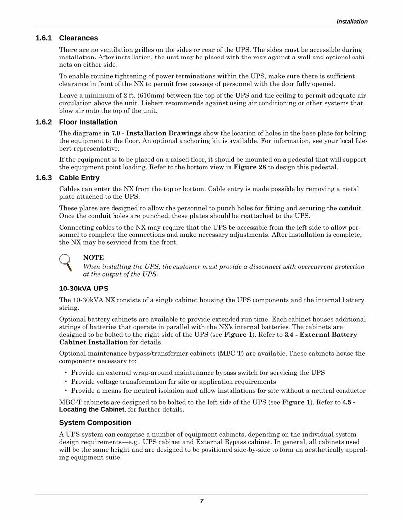
1.6.1 ClearancesThere are no ventilation grilles on the sides or rear of the UPS. The sides must be accessible during installation. After installation, the unit may be placed with the rear against a wall and optional cabi-nets on either side.
To enable routine tightening of power terminations within the UPS, make sure there is sufficient clearance in front of the NX to permit free passage of personnel with the door fully opened.
Leave a minimum of 2 ft. (610mm) between the top of the UPS and the ceiling to permit adequate air circulation above the unit. Liebert recommends against using air conditioning or other systems that blow air onto the top of the unit.
1.6.2 Floor InstallationThe diagrams in 7.0 - Installation Drawings show the location of holes in the base plate for bolting the equipment to the floor. An optional anchoring kit is available. For information, see your local Lie-bert representative.
If the equipment is to be placed on a raised floor, it should be mounted on a pedestal that will support the equipment point loading. Refer to the bottom view in Figure 28 to design this pedestal.
1.6.3 Cable EntryCables can enter the NX from the top or bottom. Cable entry is made possible by removing a metal plate attached to the UPS.
These plates are designed to allow the personnel to punch holes for fitting and securing the conduit. Once the conduit holes are punched, these plates should be reattached to the UPS.
Connecting cables to the NX may require that the UPS be accessible from the left side to allow per-sonnel to complete the connections and make necessary adjustments. After installation is complete, the NX may be serviced from the front.
10-30kVA UPSThe 10-30kVA NX consists of a single cabinet housing the UPS components and the internal battery string.
Optional battery cabinets are available to provide extended run time. Each cabinet houses additional strings of batteries that operate in parallel with the NX’s internal batteries. The cabinets are designed to be bolted to the right side of the UPS (see Figure 1). Refer to 3.4 - External Battery Cabinet Installation for details.
Optional maintenance bypass/transformer cabinets (MBC-T) are available. These cabinets house the components necessary to:
• Provide an external wrap-around maintenance bypass switch for servicing the UPS• Provide voltage transformation for site or application requirements• Provide a means for neutral isolation and allow installations for site without a neutral conductor
MBC-T cabinets are designed to be bolted to the left side of the UPS (see Figure 1). Refer to 4.5 - Locating the Cabinet, for further details.
System CompositionA UPS system can comprise a number of equipment cabinets, depending on the individual system design requirements—e.g., UPS cabinet and External Bypass cabinet. In general, all cabinets used will be the same height and are designed to be positioned side-by-side to form an aesthetically appeal-ing equipment suite.
NOTEWhen installing the UPS, the customer must provide a disconnect with overcurrent protection at the output of the UPS.
Installation
8
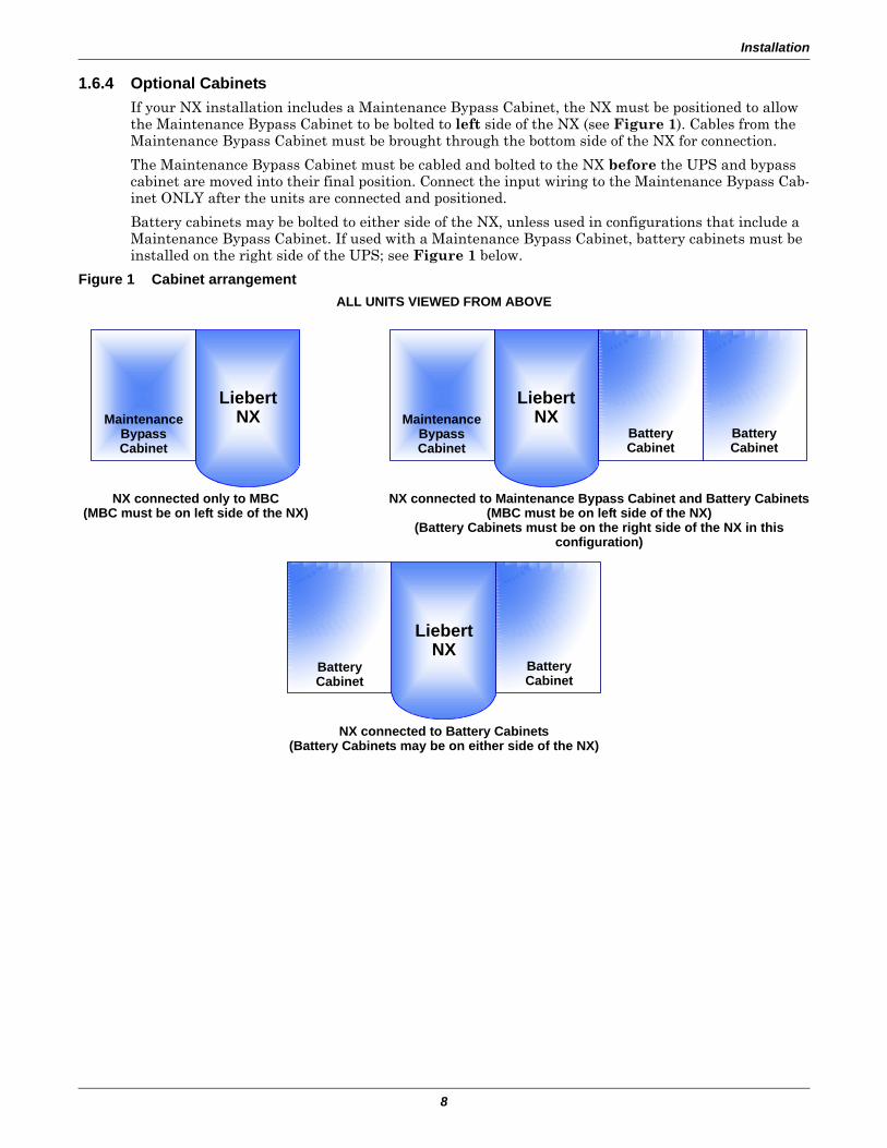
1.6.4 Optional CabinetsIf your NX installation includes a Maintenance Bypass Cabinet, the NX must be positioned to allow the Maintenance Bypass Cabinet to be bolted to left side of the NX (see Figure 1). Cables from the Maintenance Bypass Cabinet must be brought through the bottom side of the NX for connection.
The Maintenance Bypass Cabinet must be cabled and bolted to the NX before the UPS and bypass cabinet are moved into their final position. Connect the input wiring to the Maintenance Bypass Cab-inet ONLY after the units are connected and positioned.
Battery cabinets may be bolted to either side of the NX, unless used in configurations that include a Maintenance Bypass Cabinet. If used with a Maintenance Bypass Cabinet, battery cabinets must be installed on the right side of the UPS; see Figure 1 below.
Figure 1 Cabinet arrangement
NX connected only to MBC(MBC must be on left side of the NX)
NX connected to Maintenance Bypass Cabinet and Battery Cabinets(MBC must be on left side of the NX)
(Battery Cabinets must be on the right side of the NX in thisconfiguration)
LiebertNXMaintenance
BypassCabinet
BatteryCabinet
BatteryCabinet
LiebertNXMaintenance
BypassCabinet
ALL UNITS VIEWED FROM ABOVE
NX connected to Battery Cabinets(Battery Cabinets may be on either side of the NX)
LiebertNX
BatteryCabinet
BatteryCabinet
Electrical Connections
9
2.0 ELECTRICAL CONNECTIONS
The UPS requires both power and control cabling once it has been mechanically installed. All control cables must run separate from power cables in metal conduits or metal ducts that are electrically bonded to the metalwork of the cabinets to which they are connected.
2.1 Power Cabling
2.1.1 Cable RatingThe main factors affecting the choice and size of cable are voltage, current (also taking into account overcurrent), room temperature and conditions of installation of the cable.
The power cables of the system must be sized with respect to the following description:
• UPS input cables - The UPS input cables must be sized for the maximum input current, includ-ing the maximum battery recharge current, given in Table 10, with respect to the unit rating and the input AC voltage.
• UPS bypass and output cables - The bypass and output cables must be sized for the nominal output current, given in Table 10, with respect to the unit rating and the output AC voltage.
• Battery cables - Each UPS unit has its own internal batteries factory-wired. If connecting an external battery cabinet, the battery cables must be sized for the battery discharge current at the end-of-discharge voltage, as given in Table 10, with respect to the unit rating.
The power cables can be sized to suit the UPS unit rating according to Table 10.
Lug Size and Torque RequirementsRefer to Table 27 for lug size and torque requirements.
! WARNINGBefore connecting input power to the NX, ensure that you are aware of the location and operation of the overcurrent protection devices that connect the UPS input/bypass supply to the power distribution panel.
De-energize and lockout or tagout all incoming high- and low-voltage power circuits before installing cables or making any electrical connections.
NOTETable 10 gives nominal currents for determining the size of UPS power cables. Other important factors to consider include cable route length and coordination with protective devices.
Electrical Connections
10
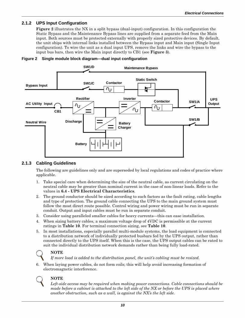
2.1.2 UPS Input ConfigurationFigure 2 illustrates the NX in a split bypass (dual-input) configuration. In this configuration the Static Bypass and the Maintenance Bypass lines are supplied from a separate feed from the Main input. Both sources must be protected externally with properly sized protective devices. By default, the unit ships with internal links installed between the Bypass input and Main input (Single Input configuration). To wire the unit as a dual input UPS, remove the links and wire the bypass to the input bus bars, then wire the Main input directly to CB1 (see Figure 3).
Figure 2 Single module block diagram—dual input configuration
2.1.3 Cabling GuidelinesThe following are guidelines only and are superseded by local regulations and codes of practice where applicable.
1. Take special care when determining the size of the neutral cable, as current circulating on the neutral cable may be greater than nominal current in the case of non-linear loads. Refer to the values in 6.4 - UPS Electrical Characteristics.
2. The ground conductor should be sized according to such factors as the fault rating, cable lengths and type of protection. The ground cable connecting the UPS to the main ground system must follow the most direct route possible. Control wiring and power wiring must be run in separate conduit. Output and input cables must be run in separate conduit.
3. Consider using paralleled smaller cables for heavy currents—this can ease installation.4. When sizing battery cables, a maximum voltage drop of 4VDC is permissible at the current
ratings in Table 10. For terminal connection sizing, see Table 10.5. In most installations, especially parallel multi-module systems, the load equipment is connected
to a distribution network of individually protected busbars fed by the UPS output, rather than connected directly to the UPS itself. When this is the case, the UPS output cables can be rated to suit the individual distribution network demands rather than being fully load-rated.
6. When laying power cables, do not form coils; this will help avoid increasing formation of electromagnetic interference.
NOTEIf more load is added to the distribution panel, the unit’s cabling must be resized.
NOTELeft-side access may be required when making power connections. Cable connections should be made before a cabinet is attached to the left side of the NX or before the UPS is placed where another obstruction, such as a wall, is against the NX’s the left side.
SW1/D
SW1/C
SW1/A
SW1/B
Maintenance Bypass
Neutral Wire
AC Utility Input
Bypass InputStatic Switch
ContactorInverterRectifier
Discharge BatteryCharger
Battery
UPSOutput
CB1
Contactor
Electrical Connections
11
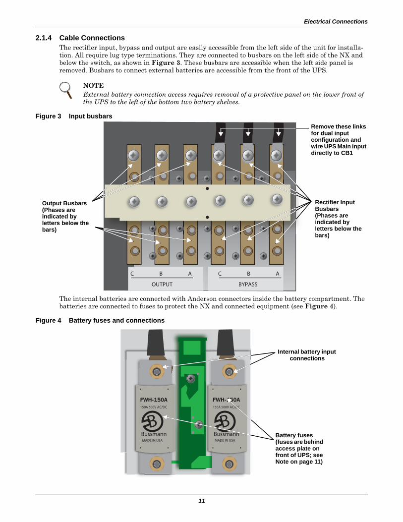
2.1.4 Cable ConnectionsThe rectifier input, bypass and output are easily accessible from the left side of the unit for installa-tion. All require lug type terminations. They are connected to busbars on the left side of the NX and below the switch, as shown in Figure 3. These busbars are accessible when the left side panel is removed. Busbars to connect external batteries are accessible from the front of the UPS.
Figure 3 Input busbars
The internal batteries are connected with Anderson connectors inside the battery compartment. The batteries are connected to fuses to protect the NX and connected equipment (see Figure 4).
Figure 4 Battery fuses and connections
NOTEExternal battery connection access requires removal of a protective panel on the lower front of the UPS to the left of the bottom two battery shelves.
C B
OUTPUT BYPASS
A C B A
Rectifier Input Busbars(Phases areindicated byletters below the bars)
Output Busbars(Phases areindicated byletters below the bars)
Remove these links for dual inputconfiguration and wire UPS Main input directly to CB1
BussmannMADE IN USA
150A 500V AC/DC
BBussmannMADE IN USA
150A 500V AC/DC
B
Internal battery input connections
Battery fuses (fuses are behind access plate on front of UPS; see Note on page 11)
Electrical Connections
12
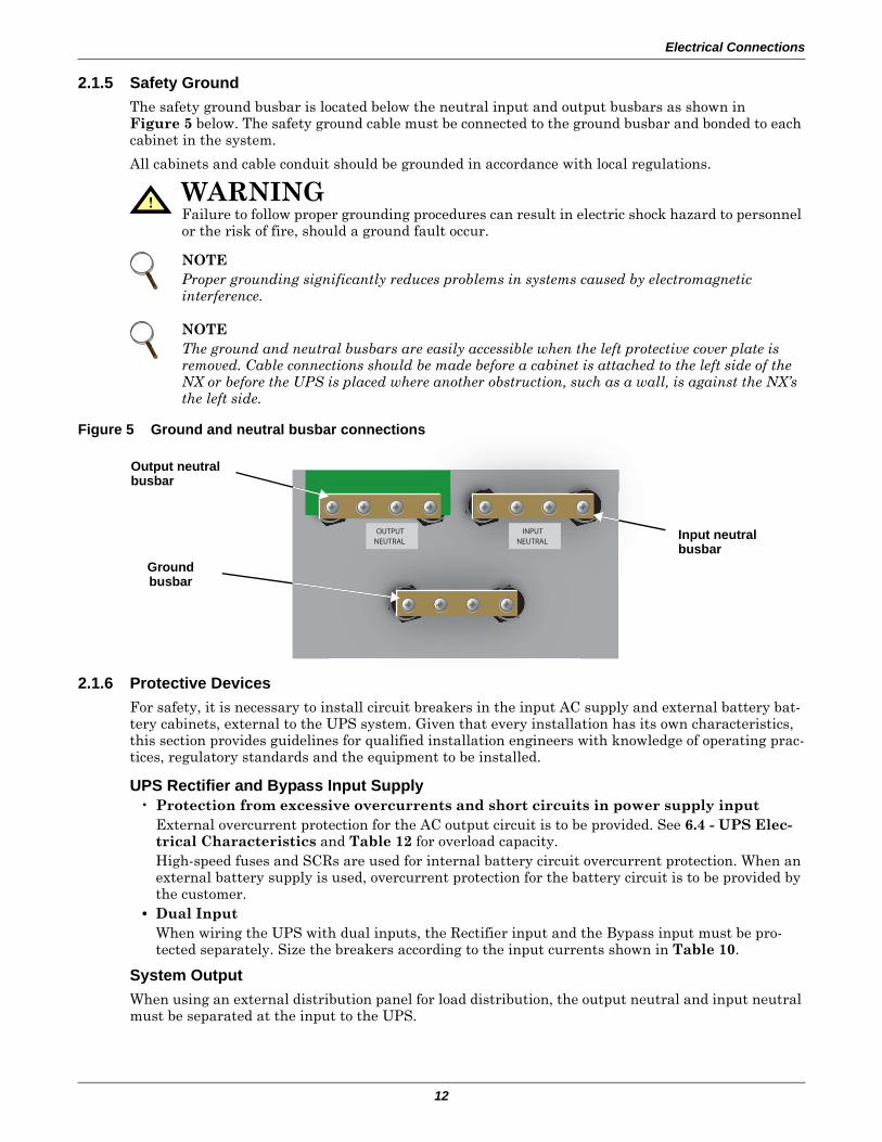
2.1.5 Safety GroundThe safety ground busbar is located below the neutral input and output busbars as shown in Figure 5 below. The safety ground cable must be connected to the ground busbar and bonded to each cabinet in the system.
All cabinets and cable conduit should be grounded in accordance with local regulations.
Figure 5 Ground and neutral busbar connections
2.1.6 Protective DevicesFor safety, it is necessary to install circuit breakers in the input AC supply and external battery bat-tery cabinets, external to the UPS system. Given that every installation has its own characteristics, this section provides guidelines for qualified installation engineers with knowledge of operating prac-tices, regulatory standards and the equipment to be installed.
UPS Rectifier and Bypass Input Supply• Protection from excessive overcurrents and short circuits in power supply input
External overcurrent protection for the AC output circuit is to be provided. See 6.4 - UPS Elec-trical Characteristics and Table 12 for overload capacity.High-speed fuses and SCRs are used for internal battery circuit overcurrent protection. When an external battery supply is used, overcurrent protection for the battery circuit is to be provided by the customer.
• Dual InputWhen wiring the UPS with dual inputs, the Rectifier input and the Bypass input must be pro-tected separately. Size the breakers according to the input currents shown in Table 10.
System OutputWhen using an external distribution panel for load distribution, the output neutral and input neutral must be separated at the input to the UPS.
! WARNINGFailure to follow proper grounding procedures can result in electric shock hazard to personnel or the risk of fire, should a ground fault occur.
NOTEProper grounding significantly reduces problems in systems caused by electromagnetic interference.
NOTEThe ground and neutral busbars are easily accessible when the left protective cover plate is removed. Cable connections should be made before a cabinet is attached to the left side of the NX or before the UPS is placed where another obstruction, such as a wall, is against the NX’s the left side.
OUTPUTNEUTRAL
INPUTNEUTRAL
Input neutral busbar
Output neutral busbar
Groundbusbar
Electrical Connections
13
2.1.7 Cabling Procedure
Once the equipment has been positioned and secured for operation, and the battery and ground col-lars have been connected (see 2.1.4 - Cable Connections), connect the power cables as described below. (Study the reference drawing in 7.0 - Installation Drawings.)
1. Verify that all incoming high and low voltage power circuits are de-energized and locked out or tagged out before installing cables or making any electrical connections.
2. Remove the left side panel to gain easier access to the connections busbars.3. Connect the safety ground and any easier bonding ground bus cables to the copper ground busbar
located on the bottom of the equipment below the power connections. All cabinets in the UPS system must be connected to the user’s ground connection.
4. Identify and make power connections with incoming cables according to Steps 5 through 11.
Common Input Connections5. For common bypass and rectifier inputs, connect the AC input supply cables between the power
distribution panel and the UPS input busbars (A-B-C terminals) and tighten the connections to 44 lb-in. (5 N-m) using the M6 bolt provided.
6. The input neutral cable must be connected to the input neutral busbar (N). See Figure 5.
Dual Input Connections7. For bypass connect the AC input supply cables between the power distribution panel and the UPS
input busbars (A-B-C terminals) and tighten the connections to 44 lb-in. (5 N-m) using the M6 bolt provided.
8. For Rectifier Input connect AC input supply cables between the power distribution panel and the UPS input circuit breaker (A-B-C terminals)
9. The bypass and rectifier input neutral cables must be connected to the input neutral busbar (N). See Figure 5.
Output System Connections—Ensure Correct Phase Rotation10. Connect the system output cables between the UPS output busbars (A-B-C N terminals) and the
critical load and tighten the connections to 44 lb-in. (5 N-m) (M6 bolt).
! CAUTIONThe operations described in this section must be performed by authorized electricians or qualified technical personnel. If you have any difficulties, contact your local Liebert representative or Liebert Global Services.
NOTEHydraulic pressure pliers, combinative tools and piston ring pliers should be used to connect AC wiring.
NOTEThe grounding and neutral bonding arrangement must comply with the National Electrical Code and all applicable local codes.
NOTEBoth the rectifier and bypass feeds MUST come from the same utility source, except if the UPS system includes either a configuration F or P external maintenance bypass cabinet.
! WARNINGIf the load equipment will not be ready to accept power on the arrival of the commissioning engineer, then ensure that the system output cables are safely isolated.
Electrical Connections
14
Internal UPS Battery ConnectionsThe UPS internal batteries will be connected at the factory, EXCEPT the Anderson connections between the shelves and to the fuses.
Observe the battery cable polarity. Be sure that the battery connector is made with the cor-rect polarity.
11. Refit all protective covers removed for cable installation
2.2 Control Cables2.2.1 Monitor Board Features
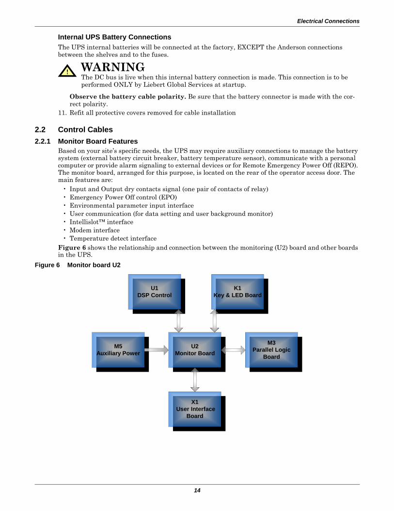
Based on your site’s specific needs, the UPS may require auxiliary connections to manage the battery system (external battery circuit breaker, battery temperature sensor), communicate with a personal computer or provide alarm signaling to external devices or for Remote Emergency Power Off (REPO). The monitor board, arranged for this purpose, is located on the rear of the operator access door. The main features are:
• Input and Output dry contacts signal (one pair of contacts of relay)• Emergency Power Off control (EPO)• Environmental parameter input interface• User communication (for data setting and user background monitor)• Intellislot™ interface• Modem interface• Temperature detect interface
Figure 6 shows the relationship and connection between the monitoring (U2) board and other boards in the UPS.
Figure 6 Monitor board U2
! WARNINGThe DC bus is live when this internal battery connection is made. This connection is to be performed ONLY by Liebert Global Services at startup.
X1 User Interface
Board
U1DSP Control
K1Key & LED Board
U2Monitor Board
M3Parallel Logic
Board
M5Auxiliary Power
Electrical Connections
15
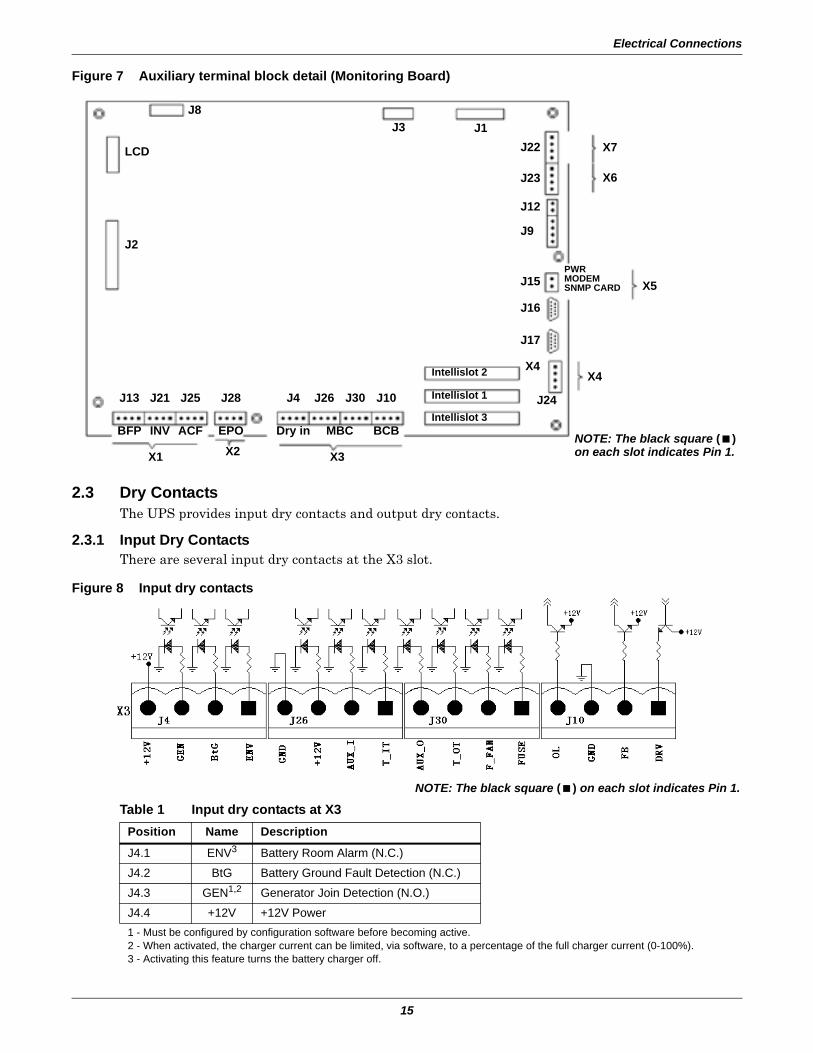
Figure 7 Auxiliary terminal block detail (Monitoring Board)
2.3 Dry ContactsThe UPS provides input dry contacts and output dry contacts.
2.3.1 Input Dry ContactsThere are several input dry contacts at the X3 slot.
Figure 8 Input dry contacts
Table 1 Input dry contacts at X3Position Name Description
J4.1 ENV3 Battery Room Alarm (N.C.)
J4.2 BtG Battery Ground Fault Detection (N.C.)
J4.3 GEN1,2 Generator Join Detection (N.O.)
J4.4 +12V +12V Power1 - Must be configured by configuration software before becoming active.2 - When activated, the charger current can be limited, via software, to a percentage of the full charger current (0-100%).3 - Activating this feature turns the battery charger off.
NOTE: The black square ( )on each slot indicates Pin 1.
J3 J1
J13 J21 J25 J28 J4 J26 J30 J10
J22
J23
J12
J9
J15
J17
J24
X4X4
J16
X1 X2 X3
Intellislot 2
Intellislot 1
Intellislot 3
J8
J2
LCD
BFP INV ACF EPO Dry in MBC BCB
X5
X6
X7
PWRMODEMSNMP CARD
NOTE: The black square ( ) on each slot indicates Pin 1.
Electrical Connections
16
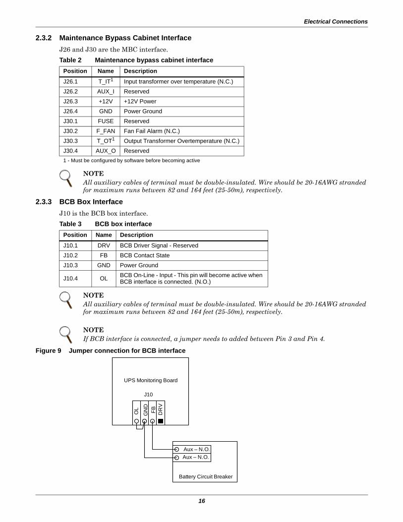
2.3.2 Maintenance Bypass Cabinet InterfaceJ26 and J30 are the MBC interface.
2.3.3 BCB Box InterfaceJ10 is the BCB box interface.
Figure 9 Jumper connection for BCB interface
Table 2 Maintenance bypass cabinet interfacePosition Name Description
J26.1 T_IT1 Input transformer over temperature (N.C.)
J26.2 AUX_I Reserved
J26.3 +12V +12V Power
J26.4 GND Power Ground
J30.1 FUSE Reserved
J30.2 F_FAN Fan Fail Alarm (N.C.)
J30.3 T_OT1 Output Transformer Overtemperature (N.C.)
J30.4 AUX_O Reserved1 - Must be configured by software before becoming active
NOTEAll auxiliary cables of terminal must be double-insulated. Wire should be 20-16AWG stranded for maximum runs between 82 and 164 feet (25-50m), respectively.
Table 3 BCB box interfacePosition Name Description
J10.1 DRV BCB Driver Signal - Reserved
J10.2 FB BCB Contact State
J10.3 GND Power Ground
J10.4 OL BCB On-Line - Input - This pin will become active when BCB interface is connected. (N.O.)
NOTEAll auxiliary cables of terminal must be double-insulated. Wire should be 20-16AWG stranded for maximum runs between 82 and 164 feet (25-50m), respectively.
NOTEIf BCB interface is connected, a jumper needs to added between Pin 3 and Pin 4.
UPS Monitoring Board
J10
OL
DR
V
GN
DFB
Battery Circuit Breaker
OL
Aux – N.O.Aux – N.O.

Electrical Connections
17
2.3.4 Output Dry ContactsThere are three output dry contact relays at the X1 slot (see Figure 10 and Table 4).
Figure 10 Output dry contacts and EPO wiring for firmware before M170
2.3.5 EPO Input—Optional
Firmware Before M200The UPS has an Emergency Power Off (EPO) function that operates by a button on the control panel or by a remote contact provided by the user. The EPO button is under a hinged, clear plastic shield.
The X2 slot, shown in Figure 10, is the remote EPO input interface. It is active when shorted from EPO-L to EPO-H.
If an external Emergency Stop facility is required, it is connected terminals EPO-L to EPO-H of the auxiliary terminal block (X2). It also is connected to the Normally Open remote stop switch between these two terminals using shielded cable (see Figure 10 and Table 5). If this function is not used, terminals EPO-L to EPO-H must be opened.
Table 4 Output dry contact relaysPosition Name Description
J13.2 BFP_O Bypass feedback protection relay. Normally open. Closed when bypass SCR is shorted.
J13.3 BFP_S Bypass feedback protection relay center
J13.4 BFP_C Bypass feedback protection relay. Normally closed. Open when bypass SCR is shorted.
J21.2 INV_O Inverter mode relay. Normally open. Closed when UPS is in inverter mode.
J21.3 INV_S Inverter mode relay center
J21.4 INV_C Inverter mode relay. Normally closed. Open when UPS is in inverter mode.
J25.2 ACF_O Main input fault relay. Normally open. Closed when main input is in fault.
J25.3 ACF_S Main input fault relay center
J25.4 ACF_C Main input fault relay. Normally closed. Open when main input is in fault.
NOTEAll auxiliary cables of terminal must be double-insulated. Wire should be 20-16AWG stranded for maximum runs between 82 and 164 feet (25-50m), respectively.
Table 5 EPO input contact relaysPosition Name Description
J28.2 EPO_L Emergency Power Off LowJ28.4 EPO_H Emergency Power Off High
NOTEThe Emergency Stop action within the UPS shuts down the rectifier, inverter and static bypass. It does not internally disconnect the input power supply.To disconnect ALL power to the UPS, open the upstream feeder breaker(s) when the remote EPO is activated.
EPO-LEPO-H
X2X1
BFP
_C
J21 J25 J28
BFP
_S
BFP
_O
INV_
O
INV_
S
INV_
C
AC
F_C
AC
F_S
AC
F_O
+12V
J13
Electrical Connections
18
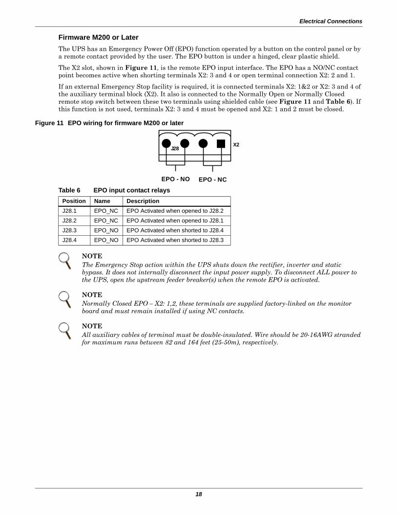
Firmware M200 or LaterThe UPS has an Emergency Power Off (EPO) function operated by a button on the control panel or by a remote contact provided by the user. The EPO button is under a hinged, clear plastic shield.
The X2 slot, shown in Figure 11, is the remote EPO input interface. The EPO has a NO/NC contact point becomes active when shorting terminals X2: 3 and 4 or open terminal connection X2: 2 and 1.
If an external Emergency Stop facility is required, it is connected terminals X2: 1&2 or X2: 3 and 4 of the auxiliary terminal block (X2). It also is connected to the Normally Open or Normally Closed remote stop switch between these two terminals using shielded cable (see Figure 11 and Table 6). If this function is not used, terminals X2: 3 and 4 must be opened and X2: 1 and 2 must be closed.
Figure 11 EPO wiring for firmware M200 or later
Table 6 EPO input contact relaysPosition Name DescriptionJ28.1 EPO_NC EPO Activated when opened to J28.2
J28.2 EPO_NC EPO Activated when opened to J28.1
J28.3 EPO_NO EPO Activated when shorted to J28.4
J28.4 EPO_NO EPO Activated when shorted to J28.3
NOTEThe Emergency Stop action within the UPS shuts down the rectifier, inverter and static bypass. It does not internally disconnect the input power supply. To disconnect ALL power to the UPS, open the upstream feeder breaker(s) when the remote EPO is activated.
NOTENormally Closed EPO – X2: 1,2, these terminals are supplied factory-linked on the monitor board and must remain installed if using NC contacts.
NOTEAll auxiliary cables of terminal must be double-insulated. Wire should be 20-16AWG stranded for maximum runs between 82 and 164 feet (25-50m), respectively.
EPO - NO EPO - NC
J28X2

Battery Installation
19
3.0 BATTERY INSTALLATION
3.1 IntroductionLiebert recommends that the batteries in external cabinets match the internal batteries in the NX in manufacturer and type.
If using multiple sets of batteries connected in parallel to provide the required battery backup run times, fit each set with an isolating device to permit working on one of the battery sets while leaving the others in service and providing backup protection.
When replacing batteries, replace with the same manufacturer and type, or equivalent. See your Lie-bert representative for a list approve batteries.
3.2 SafetySpecial care should be taken when working with the batteries associated with the NX system equip-ment. When all batteries are connected together, the battery terminal voltage may exceed 324V and is POTENTIALLY LETHAL.
3.3 UPS BatteriesThe NX's internal batteries are fully charged before the unit is shipped. During storage and transpor-tation, some charge is lost. All batteries should be recharged before use. The battery charger works only when the NX is connected to input power and turned On.
NOTEThe NX, as shipped, has 24 12-volt batteries installed internally in each unit.
! WARNINGThe NX's internal batteries are connected and energized even if the UPS is turned Off. To minimize the risk of injury, a qualified service person should disconnect internal batteries before any maintenance is performed on the unit.The center of the battery is connected to the neutral of the UPS and is grounded.A battery can present a risk of electrical shock and high short circuit current. The following precautions should be observed when working on batteries:• Remove watches, rings and other metal objects.• Use tools with insulated handles.• Wear rubber gloves and boots.• Do not lay tools or metal parts on top of batteries.• Disconnect charging source prior to connecting or disconnecting battery terminals.
NOTEFull safety instructions concerning the use and maintenance of UPS batteries are provided in the appropriate battery manufacturer's manuals, available on the manufacturer's Web site.
The battery safety information contained in this section relates to key considerations that must be taken into account during the installation design process and might affect the design outcome, depending on your installation.
Battery Installation
20
3.4 External Battery Cabinet Installation
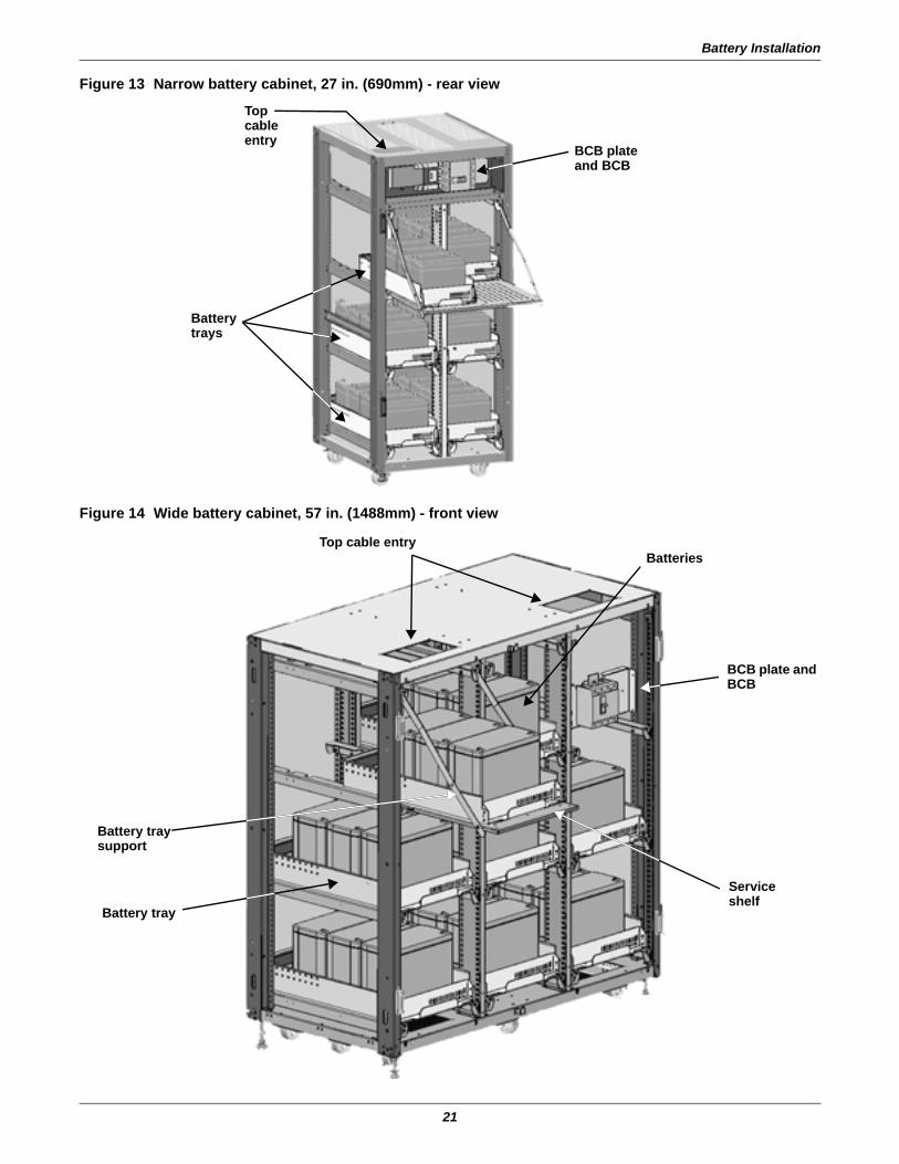
3.4.1 Matching Battery CabinetsTwo sizes of optional battery cabinets are available. Refer to Figures 13 and 14. The same model bat-tery cabinet may be installed in parallel in multiple cabinet strings for additional capacity. Battery run time depends on the cabinet model, the number of cabinets and the load on the UPS.
Handling—The battery cabinet has casters to facilitate movement over short distances. The bottoms of the battery cabinets are reinforced to permit movement by forklift over longer distances.
Inspection—Remove all panels and visually inspect the batteries, bus connections, and cabinet for any damage. Exercise caution; voltage is present within the battery cabinet even before installation. If there are signs of damage, do not proceed. Call Liebert Global Services at 1-800-542-2378.
Storage—The batteries can be stored for up to six months without appreciable deterioration. If plan-ning to store a battery cabinet for longer than six months or at temperatures higher than 77°F (25°C), contact Liebert Global Services for recommended precautions.
The following notes, in conjunction with the diagrams (Figure 13 through 12), illustrate the broad principles to be followed when fitting and connecting the majority of battery cabinet installations.
When installing an external battery cabinet that is NOT a Liebert NX battery cabinet, the customer must provide overcurrent protection. See Table 10 for sizing of protection devices.
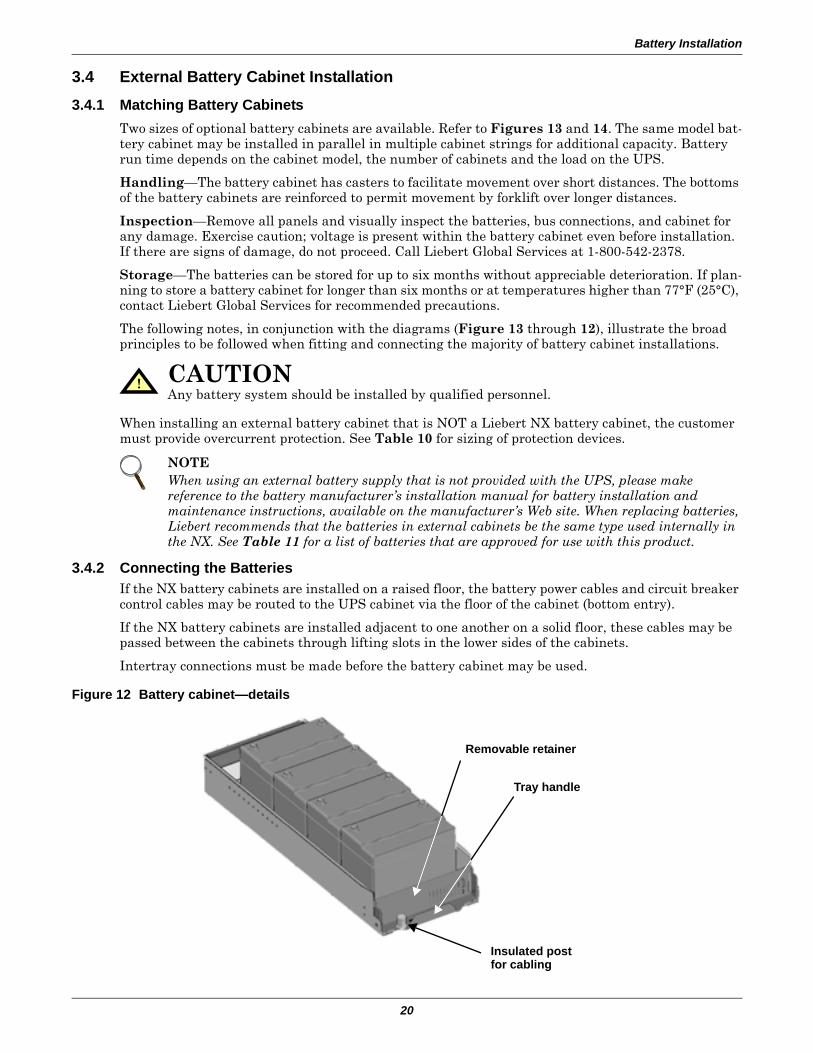
3.4.2 Connecting the BatteriesIf the NX battery cabinets are installed on a raised floor, the battery power cables and circuit breaker control cables may be routed to the UPS cabinet via the floor of the cabinet (bottom entry).
If the NX battery cabinets are installed adjacent to one another on a solid floor, these cables may be passed between the cabinets through lifting slots in the lower sides of the cabinets.
Intertray connections must be made before the battery cabinet may be used.
Figure 12 Battery cabinet—details
! CAUTIONAny battery system should be installed by qualified personnel.
NOTEWhen using an external battery supply that is not provided with the UPS, please make reference to the battery manufacturer’s installation manual for battery installation and maintenance instructions, available on the manufacturer’s Web site. When replacing batteries, Liebert recommends that the batteries in external cabinets be the same type used internally in the NX. See Table 11 for a list of batteries that are approved for use with this product.
Insulated post for cabling
Tray handle
Removable retainer
Battery Installation
21
Figure 13 Narrow battery cabinet, 27 in. (690mm) - rear view
Figure 14 Wide battery cabinet, 57 in. (1488mm) - front view
BCB plate and BCB
Battery trays
Top cableentry
Batteries
Battery tray
Top cable entry
BCB plate and BCB
Service shelf
Battery tray support
Battery Installation
22
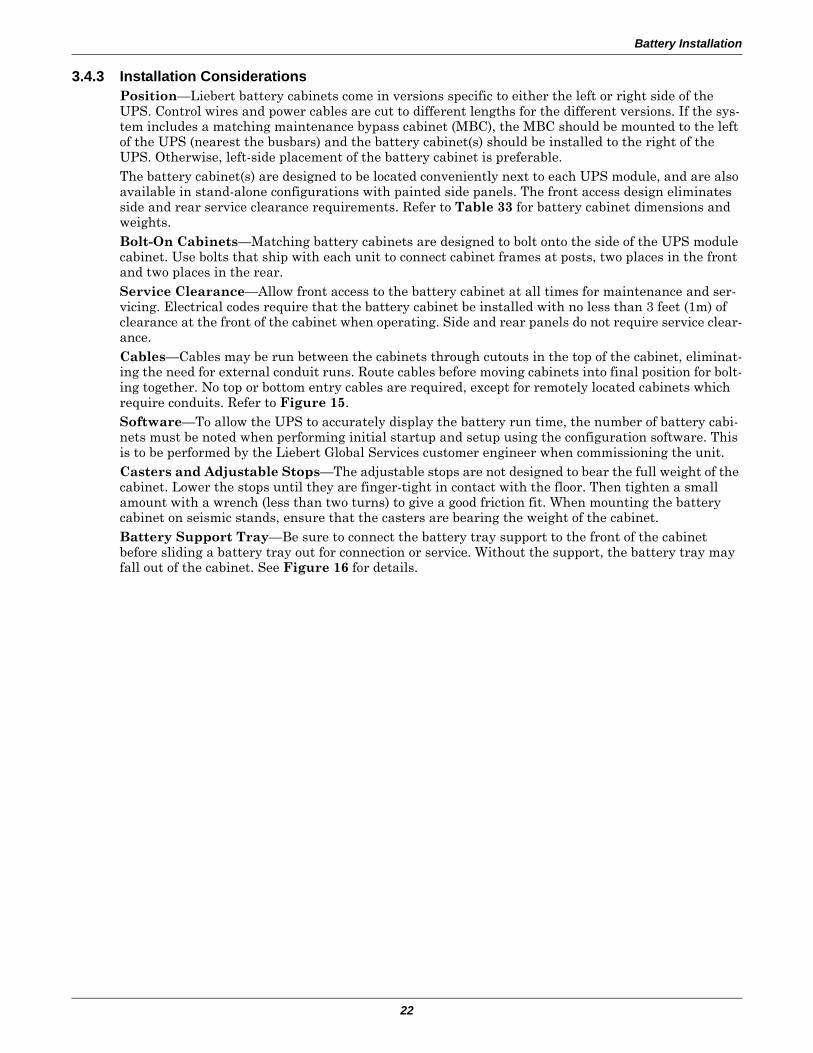
3.4.3 Installation ConsiderationsPosition—Liebert battery cabinets come in versions specific to either the left or right side of the UPS. Control wires and power cables are cut to different lengths for the different versions. If the sys-tem includes a matching maintenance bypass cabinet (MBC), the MBC should be mounted to the left of the UPS (nearest the busbars) and the battery cabinet(s) should be installed to the right of the UPS. Otherwise, left-side placement of the battery cabinet is preferable.The battery cabinet(s) are designed to be located conveniently next to each UPS module, and are also available in stand-alone configurations with painted side panels. The front access design eliminates side and rear service clearance requirements. Refer to Table 33 for battery cabinet dimensions and weights.Bolt-On Cabinets—Matching battery cabinets are designed to bolt onto the side of the UPS module cabinet. Use bolts that ship with each unit to connect cabinet frames at posts, two places in the front and two places in the rear.Service Clearance—Allow front access to the battery cabinet at all times for maintenance and ser-vicing. Electrical codes require that the battery cabinet be installed with no less than 3 feet (1m) of clearance at the front of the cabinet when operating. Side and rear panels do not require service clear-ance.Cables—Cables may be run between the cabinets through cutouts in the top of the cabinet, eliminat-ing the need for external conduit runs. Route cables before moving cabinets into final position for bolt-ing together. No top or bottom entry cables are required, except for remotely located cabinets which require conduits. Refer to Figure 15.Software—To allow the UPS to accurately display the battery run time, the number of battery cabi-nets must be noted when performing initial startup and setup using the configuration software. This is to be performed by the Liebert Global Services customer engineer when commissioning the unit.Casters and Adjustable Stops—The adjustable stops are not designed to bear the full weight of the cabinet. Lower the stops until they are finger-tight in contact with the floor. Then tighten a small amount with a wrench (less than two turns) to give a good friction fit. When mounting the battery cabinet on seismic stands, ensure that the casters are bearing the weight of the cabinet.Battery Support Tray—Be sure to connect the battery tray support to the front of the cabinet before sliding a battery tray out for connection or service. Without the support, the battery tray may fall out of the cabinet. See Figure 16 for details.
Battery Installation
23
Figure 15 Internal cable wiring from battery cabinet to Liebert NX
Figure 16 Battery tray and supports
Power cables from batteries
Power cables from output power switch
Power cables exit batterycabinet, enter Liebert NX
Power cables run across topof Liebert NX
Power cables (black) enterchannel down side of NX to power input connections
RIGHT SIDE CABLE ENTRY SHOWN; CUTOUTS ON LEFT SIDE PERMITCONNECTION FROM THAT SIDE.
Slot in support secured by screw-in connector atcorner of battery tray ...
... and notched end of support slips into slot at top cornerof battery compartment
Battery tray supports attach to interior surface of NX front door (note notched ends of supports)
Battery Installation
24
3.4.4 Connecting the Battery Cabinet to the UPSAfter the battery cabinet equipment has been positioned and secured for operation and the batteries have been connected, connect the power cables as described below. (See Figure 34.)
1. Verify that all incoming high and low voltage power circuits are de-energized and locked out or tagged out before installing cables or making any electrical connections.
2. Remove the UPS left side panel to gain access to the equipment ground busbar.3. Remove the external battery terminal block plate on the lower left side of the UPS behind the
front door.4. Remove the battery cabinet front panel to gain access to the connection bars.5. Connect the safety ground and any necessary bonding ground cables to the copper ground busbar.
(example: UPS located on the bottom of the equipment below the power connections).All cabinets in the UPS system must be connected to the user's ground connection.
6. Connect the system battery cables from the UPS battery terminals (+ N -) to battery cabinet BCB (+ N -) as shown in Figure 34. Be sure that the battery connections are made with the right polarity, and tighten the connections to 44 lb-in. (5 N-m) (M6 Bolt). Do not close the battery circuit breaker before the equipment has been commissioned.
7. Connect supplied auxiliary control cable to pins J10.2 and J10.3 on the U2 monitoring board (see 2.3 - Dry Contacts). Add a jumper wire between J10.3 and J10.4.
3.5 Non-Standard BatteriesWhen batteries other than a matching battery cabinet are used, a remote battery disconnect switch with overcurrent protection is required per the National Electrical Code. Contact your local Liebert sales representative about this option.
Install battery racks, cabinets and batteries in accordance with the manufacturer's instructions.
Verify that the battery area has adequate ventilation and battery operating temperature complies with the manufacturer's specifications and with all applicable national and local codes.
If you have any questions concerning batteries, battery racks or accessories, contact Liebert Global Services at 1-800-543-2378.
NOTEThe grounding and neutral bonding arrangement must be in accordance with the National Electrical Code and all applicable local codes.
Maintenance Bypass Cabinet
25
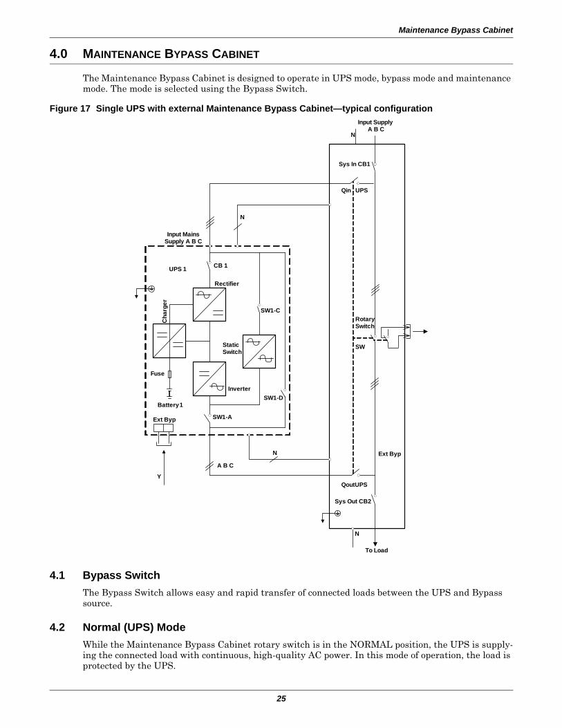
4.0 MAINTENANCE BYPASS CABINET
The Maintenance Bypass Cabinet is designed to operate in UPS mode, bypass mode and maintenance mode. The mode is selected using the Bypass Switch.
Figure 17 Single UPS with external Maintenance Bypass Cabinet—typical configuration
4.1 Bypass SwitchThe Bypass Switch allows easy and rapid transfer of connected loads between the UPS and Bypass source.
4.2 Normal (UPS) ModeWhile the Maintenance Bypass Cabinet rotary switch is in the NORMAL position, the UPS is supply-ing the connected load with continuous, high-quality AC power. In this mode of operation, the load is protected by the UPS.
Qin UPS
Battery 1
Fuse
Cha
rger
UPS 1
CB 1Rectifier
Static Switch
Inverter
SW1-C
SW1-D
SW1-A
N
Input Mains Supply A B C
N
Input Supply A B C
N
Ext Byp
A B C
Y
Sys In CB1
Rotary Switch
QoutUPS
Sys Out CB2
Ext Byp
CB 1
To Load
SW
N
Maintenance Bypass Cabinet
26
4.3 Bypass ModeWhen the Maintenance Bypass Cabinet is in the Bypass mode, it provides an alternate path for power to the connected equipment. Should the UPS need to be taken out of service for limited maintenance or repair, manual activation of the bypass will cause an immediate transfer of the equipment from the UPS inverter to the bypass source. In this mode, power will still be supplied to the UPS; however, the load is NOT protected by the UPS.
4.4 Maintenance ModeWhen the maintenance bypass cabinet is in the Maintenance mode, it provides an alternate path for power to the connected equipment. Should the UPS need to be taken out of service for limited mainte-nance or repair. In this mode of operation, no power is supplied to the UPS and the load is NOT pro-tected by the UPS.
4.5 Locating the CabinetThis Maintenance Bypass Cabinet may be mounted to the left of the UPS or installed as a stand-alone unit. In either case, ensure that the unit is in a well-ventilated area and that there is clearance for access to the switches and cable connections as required by national and local codes.
4.6 Cable Installation
4.6.1 Wiring PreparationBe sure that the unit is not connected to any AC utility power source or UPS before installing any wir-ing to this unit. This Maintenance Bypass Cabinet should be installed by a qualified / certified electri-cian.
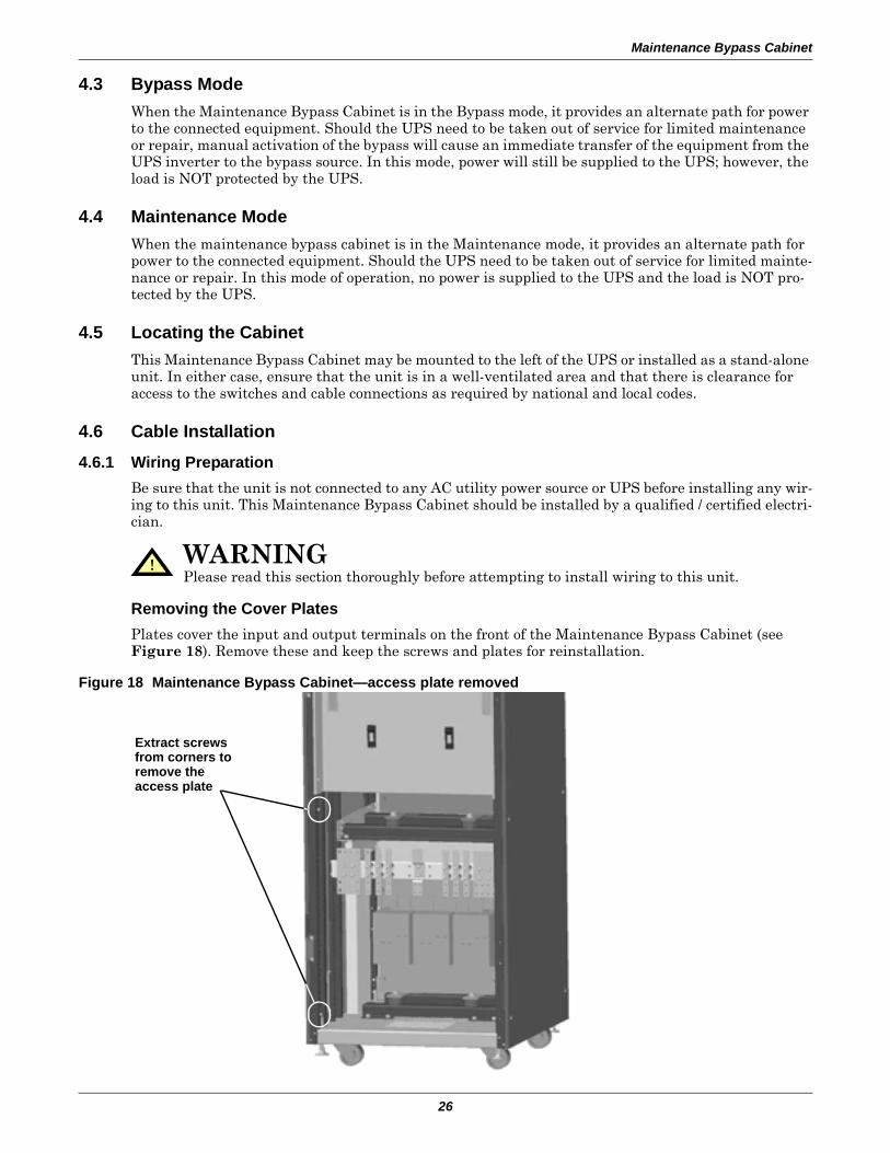
Removing the Cover PlatesPlates cover the input and output terminals on the front of the Maintenance Bypass Cabinet (see Figure 18). Remove these and keep the screws and plates for reinstallation.
Figure 18 Maintenance Bypass Cabinet—access plate removed
! WARNINGPlease read this section thoroughly before attempting to install wiring to this unit.
Extract screws from corners to remove the access plate
Maintenance Bypass Cabinet
27
4.6.2 Power Cable InstallationRefer to Tables 29, 30 and 32 when selecting cables.
4.6.3 Input/Output WiringFollow the steps below to connect the input wiring:
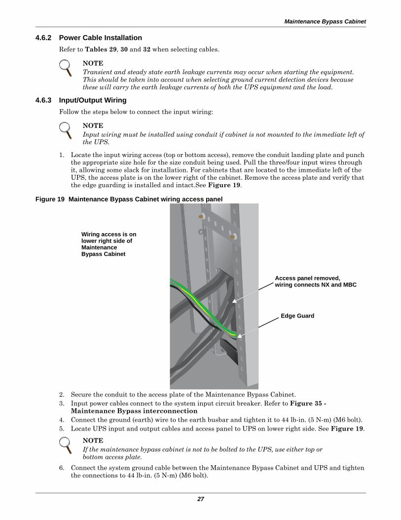
1. Locate the input wiring access (top or bottom access), remove the conduit landing plate and punch the appropriate size hole for the size conduit being used. Pull the three/four input wires through it, allowing some slack for installation. For cabinets that are located to the immediate left of the UPS, the access plate is on the lower right of the cabinet. Remove the access plate and verify that the edge guarding is installed and intact.See Figure 19.
Figure 19 Maintenance Bypass Cabinet wiring access panel
2. Secure the conduit to the access plate of the Maintenance Bypass Cabinet.3. Input power cables connect to the system input circuit breaker. Refer to Figure 35 -
Maintenance Bypass interconnection4. Connect the ground (earth) wire to the earth busbar and tighten it to 44 lb-in. (5 N-m) (M6 bolt).5. Locate UPS input and output cables and access panel to UPS on lower right side. See Figure 19.
6. Connect the system ground cable between the Maintenance Bypass Cabinet and UPS and tighten the connections to 44 lb-in. (5 N-m) (M6 bolt).
NOTETransient and steady state earth leakage currents may occur when starting the equipment. This should be taken into account when selecting ground current detection devices because these will carry the earth leakage currents of both the UPS equipment and the load.
NOTEInput wiring must be installed using conduit if cabinet is not mounted to the immediate left of the UPS.
NOTEIf the maintenance bypass cabinet is not to be bolted to the UPS, use either top or bottom access plate.
Wiring access is on lower right side of Maintenance Bypass Cabinet
Access panel removed,wiring connects NX and MBC
Edge Guard
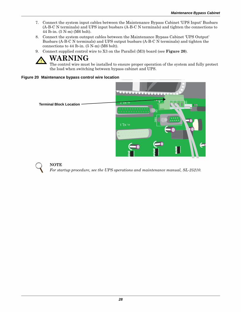
Maintenance Bypass Cabinet
28
7. Connect the system input cables between the Maintenance Bypass Cabinet 'UPS Input' Busbars (A-B-C N terminals) and UPS input busbars (A-B-C N terminals) and tighten the connections to 44 lb-in. (5 N-m) (M6 bolt).
8. Connect the system outnput cables between the Maintenance Bypass Cabinet 'UPS Output' Busbars (A-B-C N terminals) and UPS output busbars (A-B-C N terminals) and tighten the connections to 44 lb-in. (5 N-m) (M6 bolt).
9. Connect supplied control wire to X3 on the Parallel (M3) board (see Figure 20).
Figure 20 Maintenance bypass control wire location
! WARNINGThe control wire must be installed to ensure proper operation of the system and fully protect the load when switching between bypass cabinet and UPS.
NOTEFor startup procedure, see the UPS operations and maintenance manual, SL-25210.
485-P2 X2 2
485+
DB
SX
3
P1 X2 1
:XT MAINT
Terminal Block Location
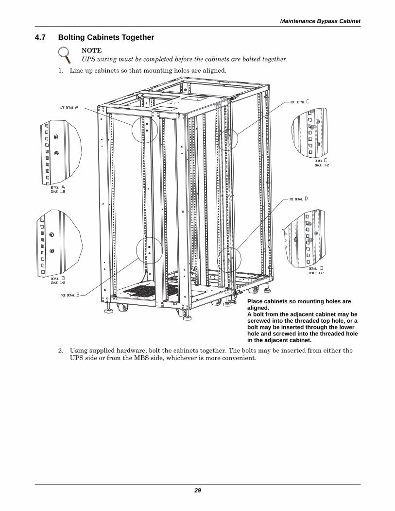
Maintenance Bypass Cabinet
29
4.7 Bolting Cabinets Together
1. Line up cabinets so that mounting holes are aligned.
2. Using supplied hardware, bolt the cabinets together. The bolts may be inserted from either the UPS side or from the MBS side, whichever is more convenient.
NOTEUPS wiring must be completed before the cabinets are bolted together.
Place cabinets so mounting holes are aligned. A bolt from the adjacent cabinet may be screwed into the threaded top hole, or a bolt may be inserted through the lower hole and screwed into the threaded hole in the adjacent cabinet.
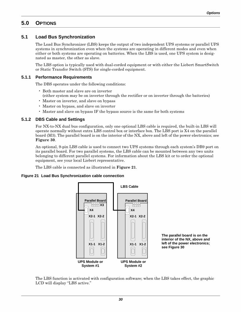
Options
30
5.0 OPTIONS
5.1 Load Bus SynchronizationThe Load Bus Synchronizer (LBS) keeps the output of two independent UPS systems or parallel UPS systems in synchronization even when the systems are operating in different modes and even when either or both systems are operating on batteries. When the LBS is used, one UPS system is desig-nated as master, the other as slave.
The LBS option is typically used with dual-corded equipment or with either the Liebert SmartSwitch or Static Transfer Switch (STS) for single-corded equipment.
5.1.1 Performance RequirementsThe DBS operates under the following conditions:
• Both master and slave are on inverter(either system may be on inverter through the rectifier or on inverter through the batteries)
• Master on inverter, and slave on bypass• Master on bypass, and slave on inverter• Master and slave on bypass IF the bypass source is the same for both systems
5.1.2 DBS Cable and SettingsFor NX-to-NX dual bus configuration, only one optional LBS cable is required, the built-in LBS will operate normally without extra LBS control box or interface box. The LBS port is X4 on the parallel board (M3). The parallel board is on the interior of the NX, above and left of the power electronics; see Figure 30.
An optional, 9-pin LBS cable is used to connect two UPS systems through each system’s DB9 port on its parallel board. For two parallel systems, the LBS cable can be mounted between any two units belonging to different parallel systems. For information about the LBS kit or to order the optional equipment, see your local Liebert representative.
The LBS cable is connected as illustrated in Figure 21.
Figure 21 Load Bus Synchronization cable connection
The LBS function is activated with configuration software; when the LBS takes effect, the graphic LCD will display “LBS active.”
X1-1 X1-2
X2-1 X2-2
Parallel Board
X4
X1-1 X1-2
X2-1 X2-2
Parallel Board
X4X3
LBS Cable
UPS Module or System #1
UPS Module or System #2
The parallel board is on the interior of the NX, above and left of the power electronics; see Figure 30
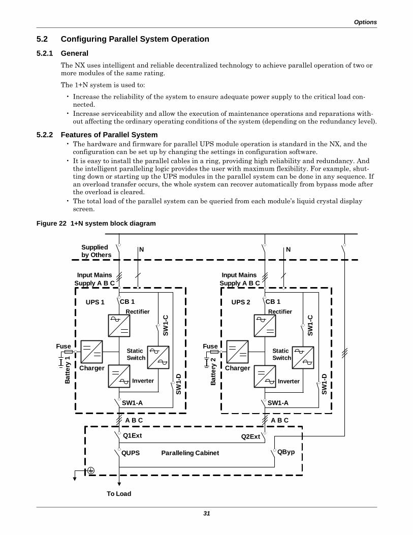
Options
31
5.2 Configuring Parallel System Operation
5.2.1 GeneralThe NX uses intelligent and reliable decentralized technology to achieve parallel operation of two or more modules of the same rating.
The 1+N system is used to:
• Increase the reliability of the system to ensure adequate power supply to the critical load con-nected.
• Increase serviceability and allow the execution of maintenance operations and reparations with-out affecting the ordinary operating conditions of the system (depending on the redundancy level).
5.2.2 Features of Parallel System• The hardware and firmware for parallel UPS module operation is standard in the NX, and the
configuration can be set up by changing the settings in configuration software.• It is easy to install the parallel cables in a ring, providing high reliability and redundancy. And
the intelligent paralleling logic provides the user with maximum flexibility. For example, shut-ting down or starting up the UPS modules in the parallel system can be done in any sequence. If an overload transfer occurs, the whole system can recover automatically from bypass mode after the overload is cleared.
• The total load of the parallel system can be queried from each module’s liquid crystal display screen.
Figure 22 1+N system block diagram
QUPS Paralleling Cabinet
Batte
ry 1
Charger
Fuse
UPS 1 CB 1Rectifier
Static Switch
Inverter
SW1-
C
SW1-
D
SW1-A
A B C
Q1Ext
Batte
ry 2
Charger
Fuse
UPS 2 CB 1Rectifier
Static Switch
Inverter
SW1-
C
SW1-
D
SW1-A
A B C
Q2Ext
To Load
QByp
Input Mains Supply A B C
Input Mains Supply A B C
NSupplied by Others
N
Appendix
32
5.2.3 Operating Principles
Redundancy ParallelingThe 1+N parallel redundant system can noticeably improve system reliability. In normal condition, none of the UPS modules work at full load. That means that even if the load is increased, the system will not transfer to bypass. And when a UPS module shuts down due to any failure, the remaining UPS modules can still power and protect the load. When redundancy is lost due to module failure or load increase, the parallel system will trigger an alarm.
5.2.4 Operation Modes SummaryThe parallel system also has operation modes such as normal, battery, bypass and maintenance bypass. All UPS modules in the 1+N parallel system operate in coordination.
• Normal Mode OperationThe load is powered by the inverters of all the UPS modules in the system. If the frequency of bypass is within the synchronous range, the inverter will be synchronized with the bypass. Other-wise, the system will operate at nominal frequency.
• Battery Mode OperationThe batteries of all UPS modules power the load through their inverters. The system operates at nominal frequency.
• Bypass Mode OperationThe condition to transfer to bypass mode is essentially the same as that of single module system. The bypass of all the UPS modules powers the load.
• Maintenance Bypass Mode OperationThe sequence to transfer to maintenance bypass mode is the same as for transferring a single-module system. The maintenance bypass switches should be switched on as synchronously as pos-sible. Thus the system can be repaired without interrupting the power supply to critical load.
5.3 Installing Parallel SystemThe basic installation procedure of parallel system is the same as that of single module system. The following sections introduce only the installation procedures specific to the parallel system.
5.3.1 Conditions for Parallel System• Each UPS module should have the same rating, the same firmware and hardware version.• Each UPS module must have the same bypass source.• The outputs of all UPS modules are connected altogether.• The main inputs can be from different sources, but the phase rotation sequence of main inputs,
bypass inputs and outputs must be correct and the same.• The parallel logic cable and load sharing cable must be connected in a ring correctly (see
Figure 23).
5.3.2 Cabinet InstallationParallel system composed of two or more UPS modules using parallel cabinet
The UPS modules that will form the 1+N system should be placed side-by-side. Each battery cabinet is placed next to its corresponding UPS module.
The parallel cabinet should be placed in the middle of the system.
5.3.3 Preliminary ChecksEach UPS module should have the same rating, the same firmware and the same hardware version. Refer to the instructions in 5.3.1 - Conditions for Parallel System.
5.3.4 Protective DevicesFor each UPS, refer to Table 10. For each system, refer to Table 31.
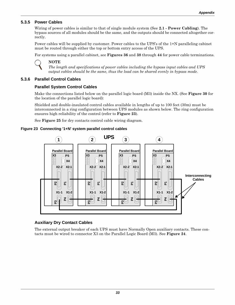
Appendix
33
5.3.5 Power CablesWiring of power cables is similar to that of single module system (See 2.1 - Power Cabling). The bypass sources of all modules should be the same, and the outputs should be connected altogether cor-rectly.
Power cables will be supplied by customer. Power cables to the UPS’s of the 1+N paralleling cabinet must be routed through either the top or bottom entry access of the UPS.
For systems using a parallel cabinet, see Figures 36 and 38 through 44 for power cable terminations.
5.3.6 Parallel Control Cables
Parallel System Control CablesMake the connections listed below on the parallel logic board (M3) inside the NX. (See Figure 30 for the location of the parallel logic board):
Shielded and double-insulated control cables available in lengths of up to 100 feet (30m) must be interconnected in a ring configuration between UPS modules as shown below. The ring configuration ensures high reliability of the control (refer to Figure 23).
See Figure 25 for dry contacts control cable wiring diagram.
Figure 23 Connecting '1+N' system parallel control cables
Auxiliary Dry Contact CablesThe external output breaker of each UPS must have Normally Open auxiliary contacts. These con-tacts must be wired to connector X3 on the Parallel Logic Board (M3). See Figure 24.
NOTEThe length and specifications of power cables including the bypass input cables and UPS output cables should be the same, thus the load can be shared evenly in bypass mode.
X1-1 X1-2
X2-2 X2-1
Parallel Board
X4
X3 P5
P3
P4P1P2
X1-1 X1-2
X2-2 X2-1
Parallel Board
X4
X3 P5
P3
P4P1P2
X1-1 X1-2
X2-2 X2-1
Parallel Board
X4
X3 P5
P3
P4P1P2
X1-1 X1-2
X2-2 X2-1
Parallel Board
X4
X3 P5P3
P4P1P2
1 2 3 4UPS
InterconnectingCables
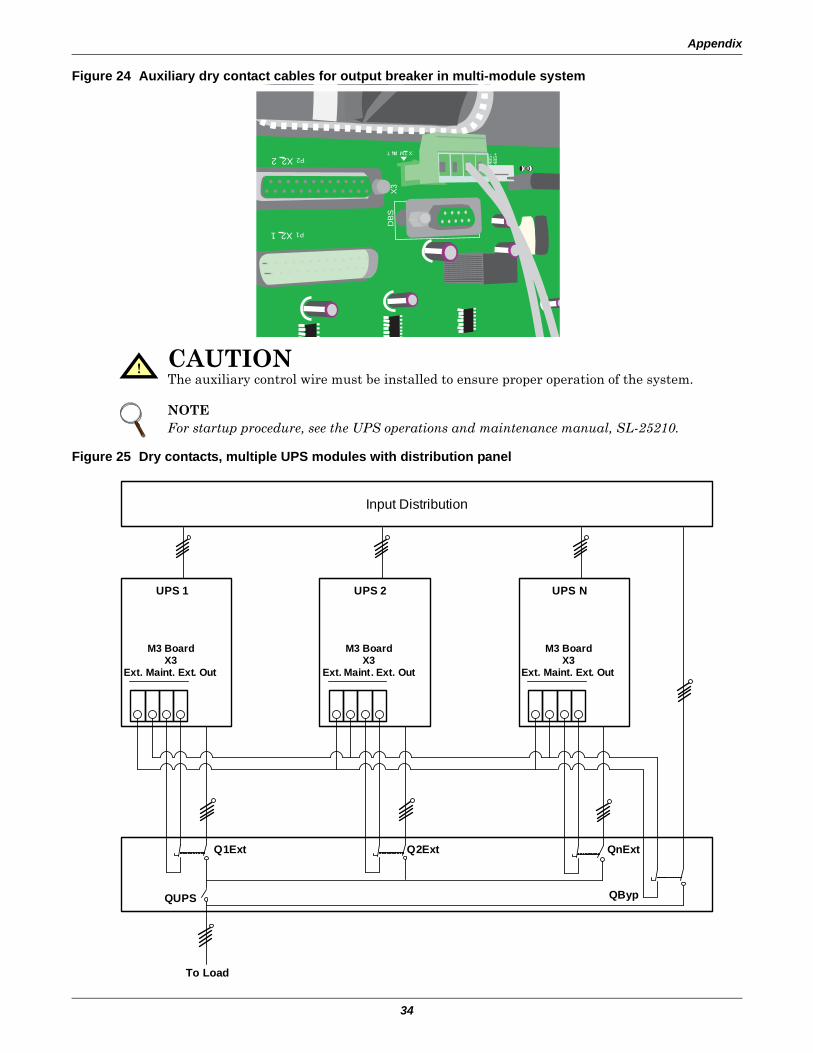
Appendix
34
Figure 24 Auxiliary dry contact cables for output breaker in multi-module system
Figure 25 Dry contacts, multiple UPS modules with distribution panel
! CAUTIONThe auxiliary control wire must be installed to ensure proper operation of the system.
NOTEFor startup procedure, see the UPS operations and maintenance manual, SL-25210.
485-
P2 X2 2
485+
DB
S
X3
P1 X2 1
:XT MAINT
Input Distribution
UPS 1
M3 BoardX3
Ext. Maint. Ext. Out
UPS 2
M3 BoardX3
Ext. Maint. Ext. Out
UPS N
M3 BoardX3
Ext. Maint. Ext. Out
To Load
QUPS QByp
Q1Ext Q2Ext QnExt
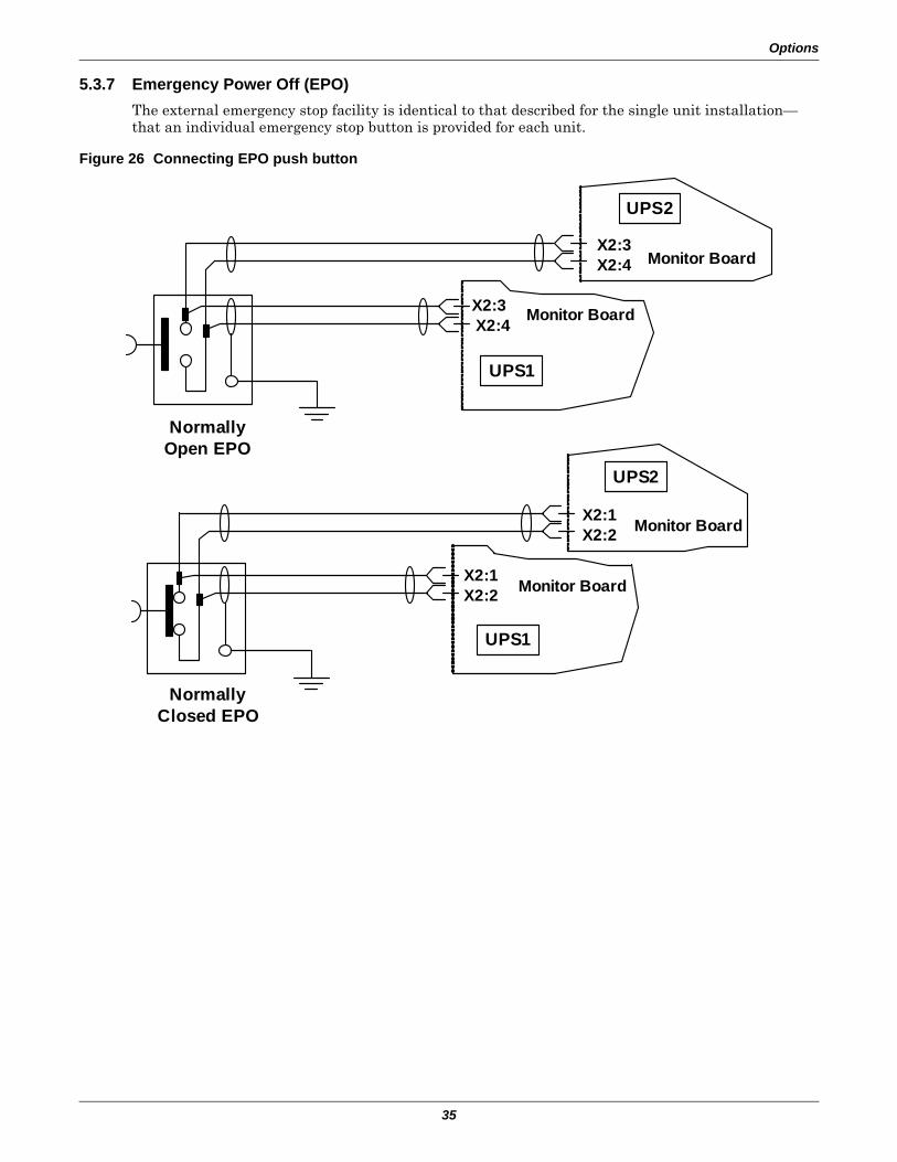
Options
35
5.3.7 Emergency Power Off (EPO)The external emergency stop facility is identical to that described for the single unit installation—that an individual emergency stop button is provided for each unit.
Figure 26 Connecting EPO push button
UPS2
UPS1
Monitor Board
Monitor Board
X2:1X2:2
X2:1X2:2
NormallyClosed EPO
UPS1
X2:3X2:4 Monitor Board
UPS2
X2:3X2:4 Monitor Board
NormallyOpen EPO
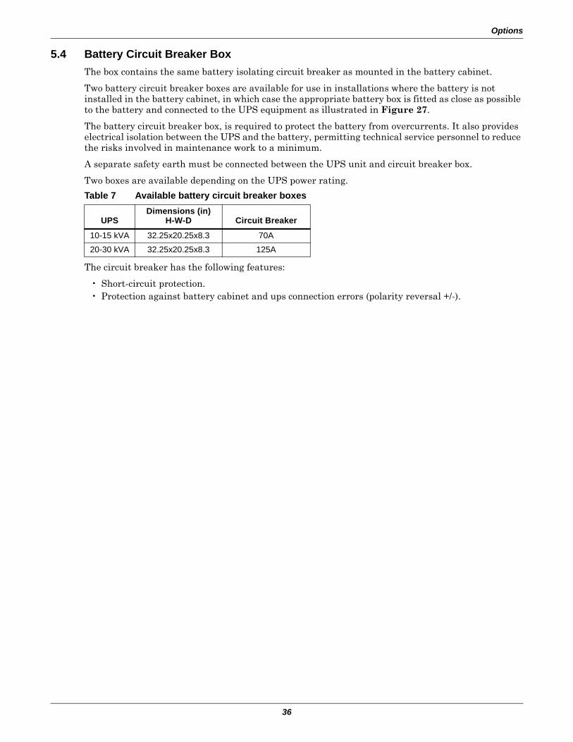
Options
36
5.4 Battery Circuit Breaker BoxThe box contains the same battery isolating circuit breaker as mounted in the battery cabinet.
Two battery circuit breaker boxes are available for use in installations where the battery is not installed in the battery cabinet, in which case the appropriate battery box is fitted as close as possible to the battery and connected to the UPS equipment as illustrated in Figure 27.
The battery circuit breaker box, is required to protect the battery from overcurrents. It also provides electrical isolation between the UPS and the battery, permitting technical service personnel to reduce the risks involved in maintenance work to a minimum.
A separate safety earth must be connected between the UPS unit and circuit breaker box.
Two boxes are available depending on the UPS power rating.
The circuit breaker has the following features:
• Short-circuit protection.• Protection against battery cabinet and ups connection errors (polarity reversal +/-).
Table 7 Available battery circuit breaker boxes
UPSDimensions (in)
H-W-D Circuit Breaker
10-15 kVA 32.25x20.25x8.3 70A
20-30 kVA 32.25x20.25x8.3 125A
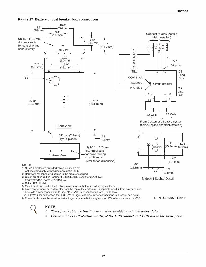
Options
37
Figure 27 Battery circuit breaker box connections
NOTE1. The signal cables in this figure must be shielded and double-insulated.2. Connect the Pes (Protection Earth) of the UPS cabinet and BCB box to the same point.
DPN U3813078 Rev. N
(7.9mm)(Typ. 4 places) .31" dia. .38"
(9.5mm)
(137mm)
(819.2mm)32.3"
2.5"(63.5mm)
(98mm)3.9"
31.5"(800.1mm)
15.0"(381mm)
20.0"(508mm)
(101.2mm)
10.8"
Top View
(274mm)5.4"
4.0"8.3"
(211.7mm)
TB1
Circuit Breaker
COM Black
N.O. Red
N.C. Blue
J10.2
J10.3 (-)
Mid
poin
t(+
)(G
ND
)
(-) (+)
(-) (+)
From Customer’s Battery System(field-supplied and field-installed)
Connect to UPS Module(field-installed)
Midpoint
(-) (+) (-) (+)
(-) (+)
Midpoint Busbar Detail
(3) 1/2" (12.7mm)dia. knockoutsfor control wiringconduit entry
(3) 1/2" (12.7mm)dia. knockoutsfor power wiringconduit entry(refer to top dimension)
NOTES:1. NEMA 1 enclosure provided which is suitable for wall mounting only. Approximate weight is 60 lb.2. Hardware for connecting cables to the breaker supplied.3. Circuit breaker, Cutler-Hammer FD4125ED13D15A02 for 20/30 kVA; FD4070ED13D15A02 for 10/15 kVA4. Color: IBM off-white.5. Mount enclosure and pull all cables into enclosure before installing dry contacts.6. Low voltage wiring needs to enter from the top of the enclosure, in separate conduit from power cables.7. Line side power connections to lugs: (1) # 6AWG per connection for 10 to 15 kVA. (1) # 2AWG per connection for 20-30 kVA to lugs:. load side power connections to busbars; see detail.8. Power cables must be sized to limit voltage drop from battery system to UPS to be a maximum 4 VDC.
23
1
456
Front View
Bottom View
CBLoadSide
CBLineSide
TB1
72 Cells 72 Cells
1"(25.4mm)
.5"(12.7mm)
1.93"(49mm)
.46"(11.8mm)
.47"(11.8mm)
.62"(15.8mm)
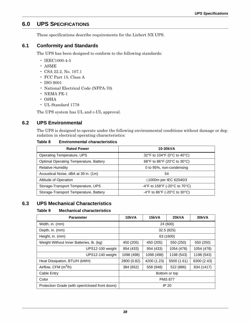
UPS Specifications
38
6.0 UPS SPECIFICATIONS
These specifications describe requirements for the Liebert NX UPS.
6.1 Conformity and StandardsThe UPS has been designed to conform to the following standards:
• IEEC1000-4-5• ASME• CSA 22.2, No. 107.1• FCC Part 15, Class A• ISO 9001• National Electrical Code (NFPA-70)• NEMA PE-1• OSHA• UL Standard 1778
The UPS system has UL and c-UL approval.
6.2 UPS Environmental The UPS is designed to operate under the following environmental conditions without damage or deg-radation in electrical operating characteristics:
6.3 UPS Mechanical Characteristics
Table 8 Environmental characteristicsRated Power 10-30kVA
Operating Temperature, UPS 32°F to 104°F (0°C to 40°C)
Optimal Operating Temperature, Battery 68°F to 86°F (20°C to 30°C)
Relative Humidity 0 to 95%, non-condensing
Acoustical Noise, dBA at 39 in. (1m) 54
Altitude of Operation ≤1000m per IEC 62040/3
Storage-Transport Temperature, UPS -4°F to 158°F (-20°C to 70°C)
Storage-Transport Temperature, Battery -4°F to 86°F (-20°C to 30°C)
Table 9 Mechanical characteristicsParameter 10kVA 15kVA 20kVA 30kVA
Width, in. (mm) 24 (600)
Depth, in. (mm) 32.5 (825)
Height, in. (mm) 63 (1600)
Weight Without Inner Batteries, lb. (kg) 450 (205) 450 (205) 550 (250) 550 (250)
UPS12-100 weight 954 (433) 954 (433) 1054 (478) 1054 (478)
UPS12-140 weight 1098 (498) 1098 (498) 1198 (543) 1198 (543)
Heat Dissipation, BTU/H (kWH) 2800 (0.82) 4200 (1.23) 5500 (1.61) 8300 (2.43)
Airflow, CFM (m3/h) 384 (652) 558 (948) 522 (886) 834 (1417)
Cable Entry Bottom or top
Color PMS 877
Protection Grade (with open/closed front doors) IP 20
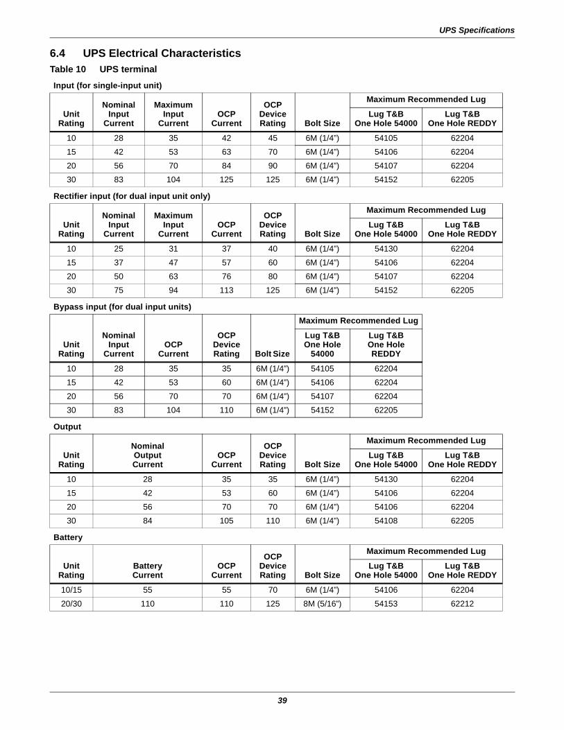
UPS Specifications
39
6.4 UPS Electrical CharacteristicsTable 10 UPS terminal
Input (for single-input unit)
UnitRating
NominalInput
Current
MaximumInput
CurrentOCP
Current
OCPDeviceRating Bolt Size
Maximum Recommended Lug
Lug T&BOne Hole 54000
Lug T&BOne Hole REDDY
10 28 35 42 45 6M (1/4”) 54105 62204
15 42 53 63 70 6M (1/4”) 54106 62204
20 56 70 84 90 6M (1/4”) 54107 62204
30 83 104 125 125 6M (1/4”) 54152 62205
Rectifier input (for dual input unit only)
UnitRating
NominalInput
Current
MaximumInput
CurrentOCP
Current
OCPDeviceRating Bolt Size
Maximum Recommended Lug
Lug T&BOne Hole 54000
Lug T&BOne Hole REDDY
10 25 31 37 40 6M (1/4”) 54130 62204
15 37 47 57 60 6M (1/4”) 54106 62204
20 50 63 76 80 6M (1/4”) 54107 62204
30 75 94 113 125 6M (1/4”) 54152 62205
Bypass input (for dual input units)
UnitRating
Nominal Input
CurrentOCP
Current
OCPDeviceRating Bolt Size
Maximum Recommended Lug
Lug T&BOne Hole
54000
Lug T&BOne Hole REDDY
10 28 35 35 6M (1/4”) 54105 62204
15 42 53 60 6M (1/4”) 54106 62204
20 56 70 70 6M (1/4”) 54107 62204
30 83 104 110 6M (1/4”) 54152 62205
Output
UnitRating
NominalOutputCurrent
OCPCurrent
OCPDeviceRating Bolt Size
Maximum Recommended Lug
Lug T&BOne Hole 54000
Lug T&BOne Hole REDDY
10 28 35 35 6M (1/4”) 54130 62204
15 42 53 60 6M (1/4”) 54106 62204
20 56 70 70 6M (1/4”) 54106 62204
30 84 105 110 6M (1/4”) 54108 62205
Battery
UnitRating
BatteryCurrent
OCPCurrent
OCPDeviceRating Bolt Size
Maximum Recommended Lug
Lug T&BOne Hole 54000
Lug T&BOne Hole REDDY
10/15 55 55 70 6M (1/4”) 54106 62204
20/30 110 110 125 8M (5/16”) 54153 62212

UPS Specifications
40
6.4.1 Battery Manufacturers and ModelsEither of two manufacturers’ batteries will be installed in the NX 10-30 kVA 208V as shipped. Below are the battery makers and the models they supply.
6.4.2 Input Rectifier
6.4.3 DC Intermediate Circuit
Table 11 Approved batteriesBattery Manufacturer Models Supplied
Enersys Yuasa NPX-80FR NPX-100FR NPX-150FR
C&D Dynasty UPS12-100MR UPS12-140MR -
Table 12 Rectifier input powerRated Power 10kVA 15kVA 20kVA 30kVA
Rated Voltage, VAC 120/208
Supply 3-phase, 4-wire plus ground
Input Voltage Tolerance, VAC (without derating) 166-239
Frequency, Hz 50 / 60
Input Frequency Tolerance % ±10
Power Factor ≤ 0.99 at full load≤ 0.95 at 50% load
Harmonic Current Less than 4% at full rated UPS output load
Input Current,1 Nominal, A 28 42 56 83
Output Current, Nominal, A 28 42 56 83Notes:1. Overload capacity of input current: 100% Imax <I<125% Imax:
125% Imax <I<150% Imax:I>150%:
10 min.1 min.Limits input current immediately
Table 13 DC intermediate circuitRated Power 10kVA 15kVA 20kVA 30kVA
Recommended number of lead-acid batteriesNumber of batteries is 24 jars (12V per jar), or 144 cells (2V per cell) for VRLA. The unit is shipped with a nominal voltage of 288VDC.
Recommended float charge voltage 2.27VDC*
Recommended boost charge voltage 2.3VDC*
Recommended end of discharge voltage 1.65-1.8 VDC
Maximum recharge battery current, A 7.5 7.5 15 15
Maximum boost charge duration, min.* 1440
Boost-float threshold current, A* 0.1 C default
Temperature voltage compensation, mV/°C* 3
Ripple voltage superimposed % ≤ 1* Set by configuration software and based on usage of VLRA batteries.
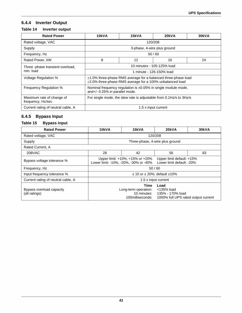
UPS Specifications
41
6.4.4 Inverter Output
6.4.5 Bypass Input
Table 14 Inverter outputRated Power 10kVA 15kVA 20kVA 30kVA
Rated voltage, VAC 120/208
Supply 3-phase, 4-wire plus ground
Frequency, Hz 50 / 60
Rated Power, kW 8 12 16 24
Three -phase transient overload,min. load
10 minutes - 105-125% load
1 minute - 126-150% load
Voltage Regulation % ±1.0% three-phase RMS average for a balanced three-phase load±2.0% three-phase RMS average for a 100% unbalanced load
Frequency Regulation % Nominal frequency regulation is ±0.05% in single module mode,and+/- 0.25% in parallel mode.
Maximum rate of change of frequency, Hz/sec
For single mode, the slew rate is adjustable from 0.1Hz/s to 3Hz/s
Current rating of neutral cable, A 1.5 x input current
Table 15 Bypass inputRated Power 10kVA 15kVA 20kVA 30kVA
Rated voltage, VAC 120/208Supply Three-phase, 4-wire plus groundRated Current, A
208VAC 28 42 56 83
Bypass voltage tolerance % Upper limit: +10%, +15% or +20%Lower limit: -10%, -20%, -30% or -40%
Upper limit default: +15%Lower limit default: -20%
Frequency, Hz 50 / 60Input frequency tolerance % ± 10 or ± 20%; default ±10%Current rating of neutral cable, A 1.5 x input current
Bypass overload capacity(all ratings)
TimeLong-term operation:
10 minutes:100milliseconds:
Load<135% load135% - 170% load1000% full UPS rated output current
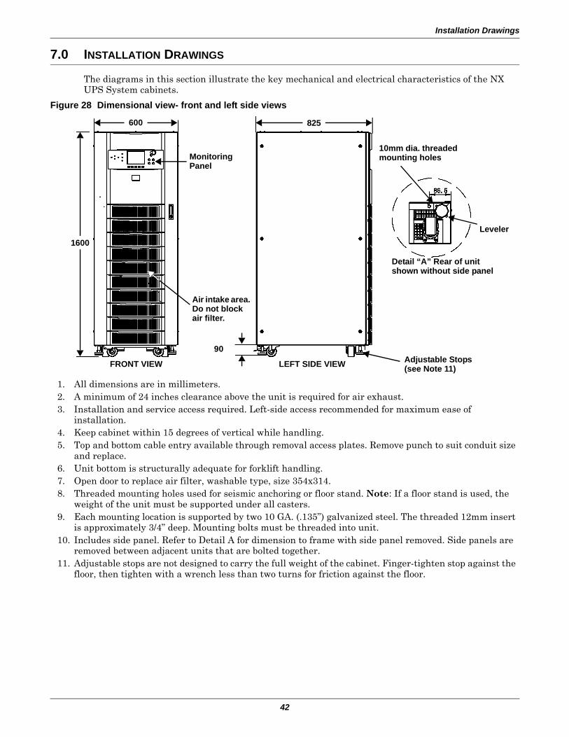
Installation Drawings
42
7.0 INSTALLATION DRAWINGS
The diagrams in this section illustrate the key mechanical and electrical characteristics of the NX UPS System cabinets.
Figure 28 Dimensional view- front and left side views
1. All dimensions are in millimeters.2. A minimum of 24 inches clearance above the unit is required for air exhaust.3. Installation and service access required. Left-side access recommended for maximum ease of
installation.4. Keep cabinet within 15 degrees of vertical while handling.5. Top and bottom cable entry available through removal access plates. Remove punch to suit conduit size
and replace.6. Unit bottom is structurally adequate for forklift handling.7. Open door to replace air filter, washable type, size 354x314.8. Threaded mounting holes used for seismic anchoring or floor stand. Note: If a floor stand is used, the
weight of the unit must be supported under all casters.9. Each mounting location is supported by two 10 GA. (.135”) galvanized steel. The threaded 12mm insert
is approximately 3/4” deep. Mounting bolts must be threaded into unit.10. Includes side panel. Refer to Detail A for dimension to frame with side panel removed. Side panels are
removed between adjacent units that are bolted together.11. Adjustable stops are not designed to carry the full weight of the cabinet. Finger-tighten stop against the
floor, then tighten with a wrench less than two turns for friction against the floor.
Monitoring Panel
Air intake area. Do not block air filter.
FRONT VIEW LEFT SIDE VIEW
10mm dia. threaded mounting holes
Detail “A” Rear of unit shown without side panel
Adjustable Stops(see Note 11)
825600
1600
90
Leveler
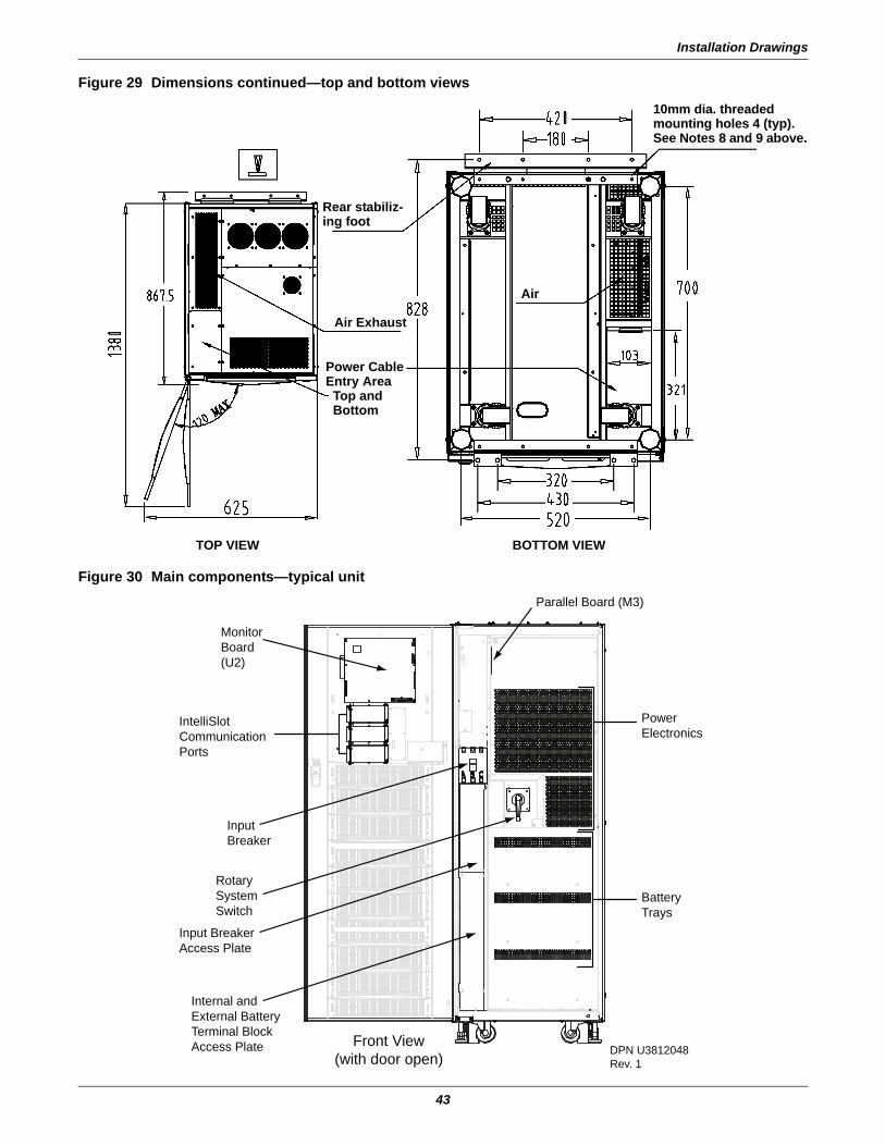
Installation Drawings
43
Figure 29 Dimensions continued—top and bottom views
Figure 30 Main components—typical unit
Rear stabiliz-ing foot
Air Exhaust
Power Cable Entry Area
Top andBottom
Air
10mm dia. threaded mounting holes 4 (typ). See Notes 8 and 9 above.
TOP VIEW BOTTOM VIEW
MonitorBoard(U2)
IntelliSlot Communication Ports
Input Breaker
Input Breaker Access Plate
Internal and External Battery Terminal Block Access Plate
Battery Trays
Power Electronics
Parallel Board (M3)
Front View (with door open) DPN U3812048
Rev. 1
Rotary System Switch
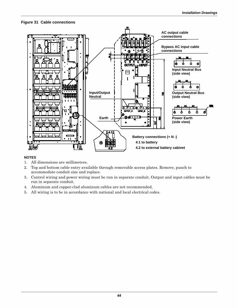
Installation Drawings
44
Figure 31 Cable connections
NOTES1. All dimensions are millimeters.2. Top and bottom cable entry available through removable access plates. Remove, punch to
accommodate conduit size and replace.3. Control wiring and power wiring must be run in separate conduit. Output and input cables must be
run in separate conduit.4. Aluminum and copper-clad aluminum cables are not recommended,5. All wiring is to be in accordance with national and local electrical codes.
Input/Output Neutral
Bypass AC input cable connections
AC output cableconnections
Input Neutral Bus(side view)
Output Neutral Bus(side view)
4.2 to external battery cabinet
Earth Power Earth(side view)
Battery connections (+ N -) 4.1 to battery
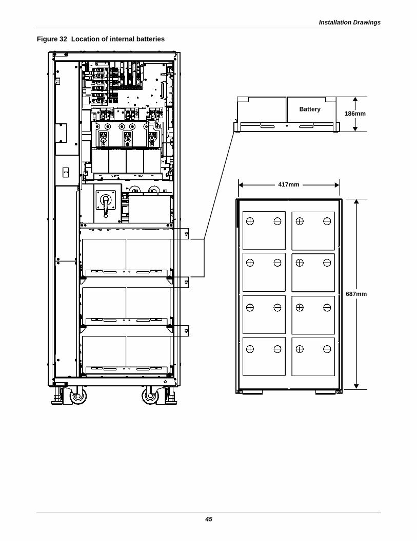
Installation Drawings
45
Figure 32 Location of internal batteries
Battery
417mm
687mm
186mm
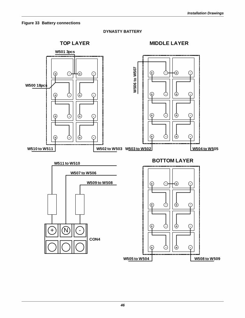
Installation Drawings
46
Figure 33 Battery connections
+ -
+ -
+ -
+ -
+ -
+ -
+ -
-+
+ -
+ -
+ -
+ -
+ -
+ -
+ -
-+
+ -
+ -
+ -
+ -
+ -
+ -
+ -
-+
-N+
W501 3pcs
W500 18pcs
W510 to W511 W502 to W503 W503 to W502 W504 to W505
W511 to W510
W507 to W506
W509 to W508
W50
6 to
W50
7
TOP LAYER MIDDLE LAYER
BOTTOM LAYER
W505 to W504 W508 to W509
CON4
DYNASTY BATTERY
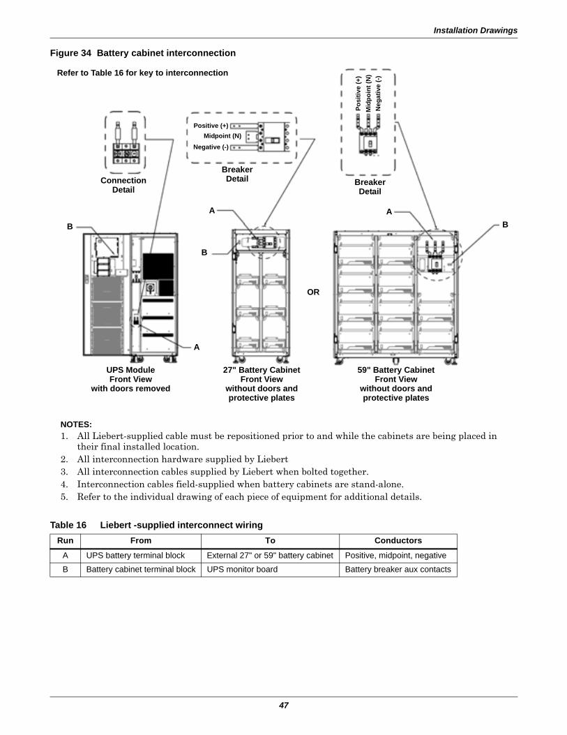
Installation Drawings
47
Figure 34 Battery cabinet interconnection
Table 16 Liebert -supplied interconnect wiringRun From To Conductors
A UPS battery terminal block External 27" or 59" battery cabinet Positive, midpoint, negative
B Battery cabinet terminal block UPS monitor board Battery breaker aux contacts
Refer to Table 16 for key to interconnection
UPS ModuleFront View
with doors removed
27" Battery CabinetFront View
without doors andprotective plates
59" Battery CabinetFront View
without doors andprotective plates
Connection Detail
Breaker Detail Breaker
Detail
Posi
tive
(+)
Mid
poin
t (N
)N
egat
ive
(-)
Positive (+)Midpoint (N)
Negative (-)
A
B
B
A
OR
BA
NOTES:1. All Liebert-supplied cable must be repositioned prior to and while the cabinets are being placed in
their final installed location.2. All interconnection hardware supplied by Liebert3. All interconnection cables supplied by Liebert when bolted together.4. Interconnection cables field-supplied when battery cabinets are stand-alone.5. Refer to the individual drawing of each piece of equipment for additional details.
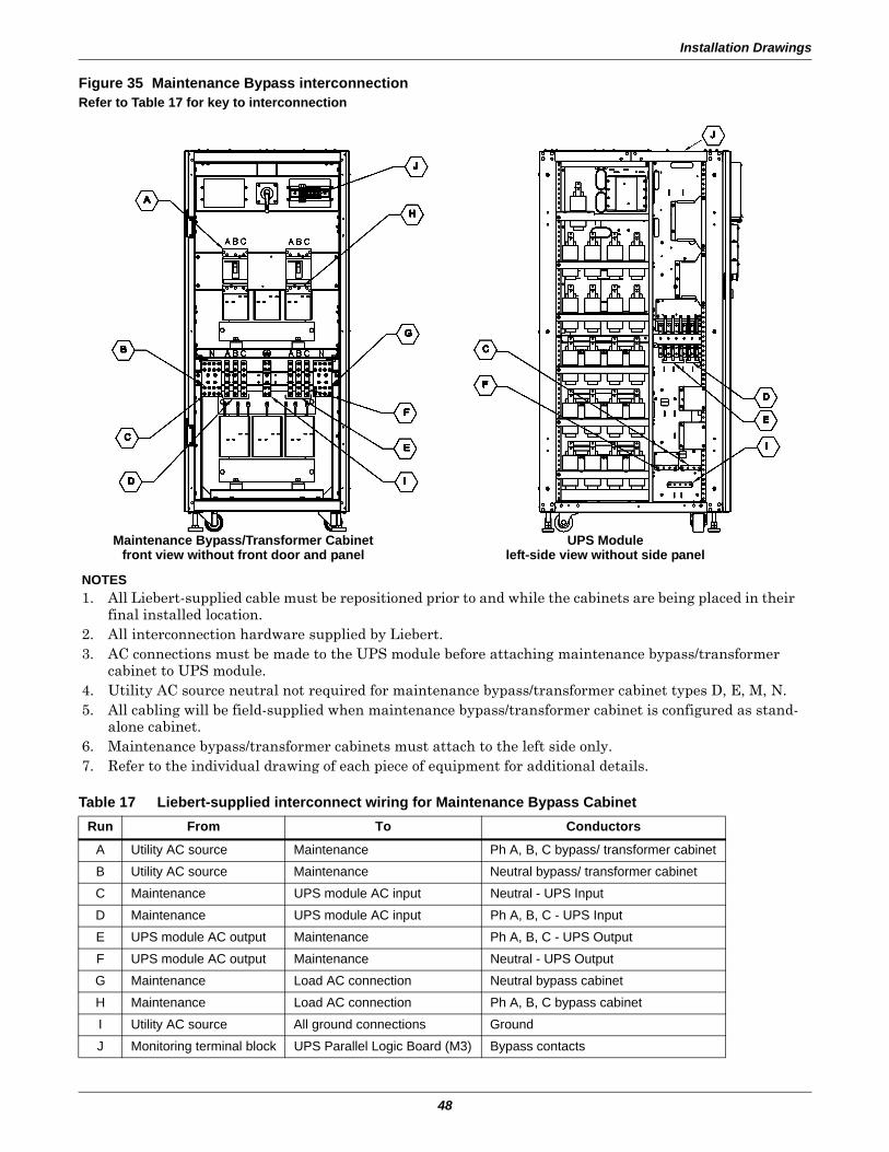
Installation Drawings
48
Figure 35 Maintenance Bypass interconnection
Table 17 Liebert-supplied interconnect wiring for Maintenance Bypass CabinetRun From To Conductors
A Utility AC source Maintenance Ph A, B, C bypass/ transformer cabinet
B Utility AC source Maintenance Neutral bypass/ transformer cabinet
C Maintenance UPS module AC input Neutral - UPS Input
D Maintenance UPS module AC input Ph A, B, C - UPS Input
E UPS module AC output Maintenance Ph A, B, C - UPS Output
F UPS module AC output Maintenance Neutral - UPS Output
G Maintenance Load AC connection Neutral bypass cabinet
H Maintenance Load AC connection Ph A, B, C bypass cabinet
I Utility AC source All ground connections Ground
J Monitoring terminal block UPS Parallel Logic Board (M3) Bypass contacts
NOTES1. All Liebert-supplied cable must be repositioned prior to and while the cabinets are being placed in their
final installed location.2. All interconnection hardware supplied by Liebert.3. AC connections must be made to the UPS module before attaching maintenance bypass/transformer
cabinet to UPS module.4. Utility AC source neutral not required for maintenance bypass/transformer cabinet types D, E, M, N.5. All cabling will be field-supplied when maintenance bypass/transformer cabinet is configured as stand-
alone cabinet.6. Maintenance bypass/transformer cabinets must attach to the left side only.7. Refer to the individual drawing of each piece of equipment for additional details.
Refer to Table 17 for key to interconnection
Maintenance Bypass/Transformer Cabinetfront view without front door and panel
UPS Moduleleft-side view without side panel
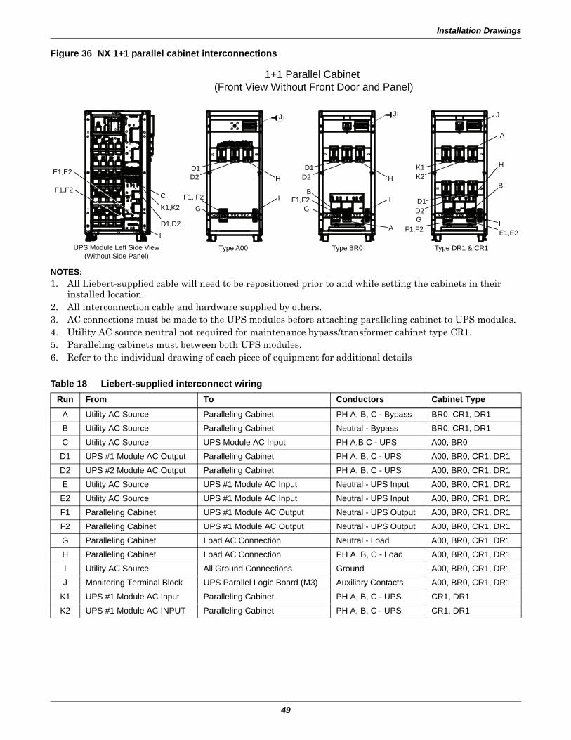
Installation Drawings
49
Figure 36 NX 1+1 parallel cabinet interconnections
Table 18 Liebert-supplied interconnect wiringRun From To Conductors Cabinet Type
A Utility AC Source Paralleling Cabinet PH A, B, C - Bypass BR0, CR1, DR1
B Utility AC Source Paralleling Cabinet Neutral - Bypass BR0, CR1, DR1
C Utility AC Source UPS Module AC Input PH A,B,C - UPS A00, BR0
D1 UPS #1 Module AC Output Paralleling Cabinet PH A, B, C - UPS A00, BR0, CR1, DR1
D2 UPS #2 Module AC Output Paralleling Cabinet PH A, B, C - UPS A00, BR0, CR1, DR1
E Utility AC Source UPS #1 Module AC Input Neutral - UPS Input A00, BR0, CR1, DR1
E2 Utility AC Source UPS #1 Module AC Input Neutral - UPS Input A00, BR0, CR1, DR1
F1 Paralleling Cabinet UPS #1 Module AC Output Neutral - UPS Output A00, BR0, CR1, DR1
F2 Paralleling Cabinet UPS #1 Module AC Output Neutral - UPS Output A00, BR0, CR1, DR1
G Paralleling Cabinet Load AC Connection Neutral - Load A00, BR0, CR1, DR1
H Paralleling Cabinet Load AC Connection PH A, B, C - Load A00, BR0, CR1, DR1
I Utility AC Source All Ground Connections Ground A00, BR0, CR1, DR1
J Monitoring Terminal Block UPS Parallel Logic Board (M3) Auxiliary Contacts A00, BR0, CR1, DR1
K1 UPS #1 Module AC Input Paralleling Cabinet PH A, B, C - UPS CR1, DR1
K2 UPS #1 Module AC INPUT Paralleling Cabinet PH A, B, C - UPS CR1, DR1
G
Type A00
D1D2 H
J
I
Type BR0
G
B
A
I
J
Type DR1 & CR1
I
B
H
A
J
E1,E2
D1,D2
I
K1,K2
CF1,F2
F1, F2 F1,F2
D1D2 H
F1,F2
D1D2G
K1K2
E1,E2
1+1 Parallel Cabinet (Front View Without Front Door and Panel)
UPS Module Left Side View(Without Side Panel)
NOTES:1. All Liebert-supplied cable will need to be repositioned prior to and while setting the cabinets in their
installed location.2. All interconnection cable and hardware supplied by others.3. AC connections must be made to the UPS modules before attaching paralleling cabinet to UPS modules.4. Utility AC source neutral not required for maintenance bypass/transformer cabinet type CR1.5. Paralleling cabinets must between both UPS modules.6. Refer to the individual drawing of each piece of equipment for additional details
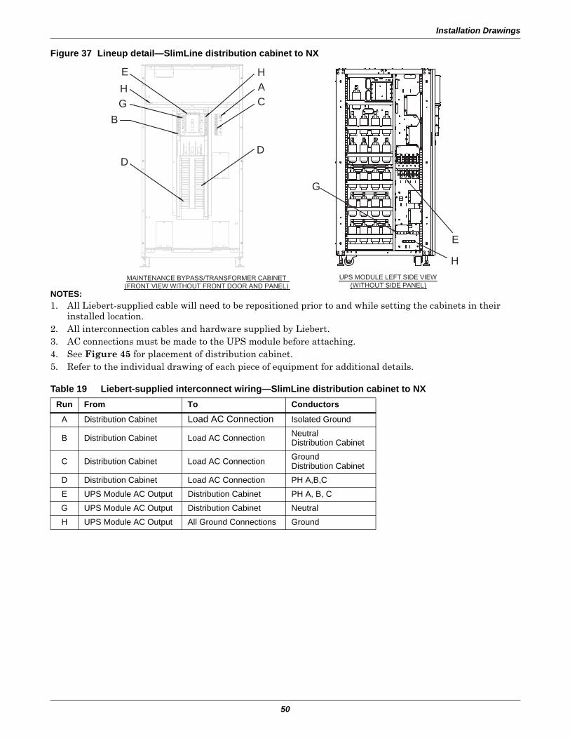
Installation Drawings
50
Figure 37 Lineup detail—SlimLine distribution cabinet to NX
Table 19 Liebert-supplied interconnect wiring—SlimLine distribution cabinet to NXRun From To Conductors
A Distribution Cabinet Load AC Connection Isolated Ground
B Distribution Cabinet Load AC Connection NeutralDistribution Cabinet
C Distribution Cabinet Load AC Connection GroundDistribution Cabinet
D Distribution Cabinet Load AC Connection PH A,B,C
E UPS Module AC Output Distribution Cabinet PH A, B, C
G UPS Module AC Output Distribution Cabinet Neutral
H UPS Module AC Output All Ground Connections Ground
E
E
H
GB
D
G
HAC
D
H
NOTES:1. All Liebert-supplied cable will need to be repositioned prior to and while setting the cabinets in their
installed location.2. All interconnection cables and hardware supplied by Liebert.3. AC connections must be made to the UPS module before attaching.4. See Figure 45 for placement of distribution cabinet.5. Refer to the individual drawing of each piece of equipment for additional details.
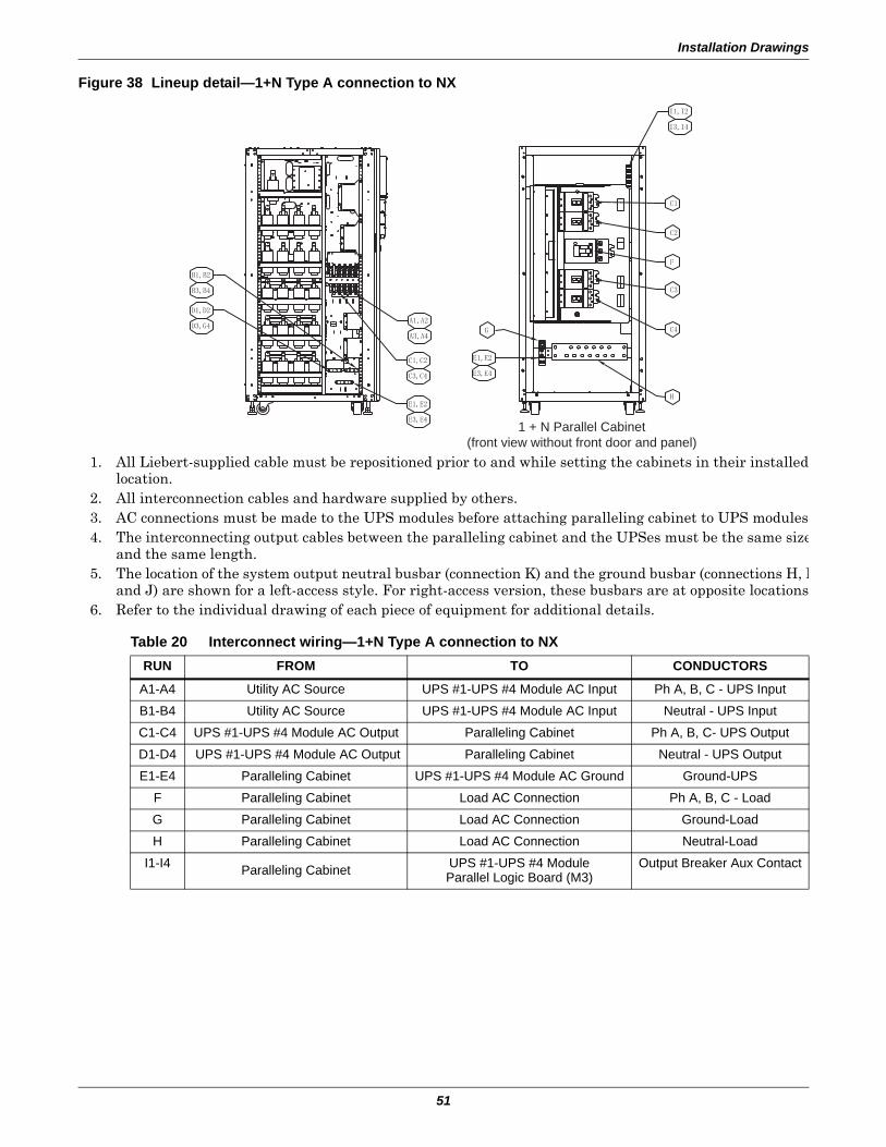
Installation Drawings
51
Figure 38 Lineup detail—1+N Type A connection to NX
Table 20 Interconnect wiring—1+N Type A connection to NXRUN FROM TO CONDUCTORS
A1-A4 Utility AC Source UPS #1-UPS #4 Module AC Input Ph A, B, C - UPS Input
B1-B4 Utility AC Source UPS #1-UPS #4 Module AC Input Neutral - UPS Input
C1-C4 UPS #1-UPS #4 Module AC Output Paralleling Cabinet Ph A, B, C- UPS Output
D1-D4 UPS #1-UPS #4 Module AC Output Paralleling Cabinet Neutral - UPS Output
E1-E4 Paralleling Cabinet UPS #1-UPS #4 Module AC Ground Ground-UPS
F Paralleling Cabinet Load AC Connection Ph A, B, C - Load
G Paralleling Cabinet Load AC Connection Ground-Load
H Paralleling Cabinet Load AC Connection Neutral-Load
I1-I4 Paralleling Cabinet UPS #1-UPS #4 ModuleParallel Logic Board (M3)
Output Breaker Aux Contact
1 + N Parallel Cabinet(front view without front door and panel)
1. All Liebert-supplied cable must be repositioned prior to and while setting the cabinets in their installed location.
2. All interconnection cables and hardware supplied by others.3. AC connections must be made to the UPS modules before attaching paralleling cabinet to UPS modules4. The interconnecting output cables between the paralleling cabinet and the UPSes must be the same size
and the same length.5. The location of the system output neutral busbar (connection K) and the ground busbar (connections H, I
and J) are shown for a left-access style. For right-access version, these busbars are at opposite locations6. Refer to the individual drawing of each piece of equipment for additional details.

Installation Drawings
52
Figure 39 Lineup detail—1+N Type A1 connection to NX
Table 21 Interconnect wiring—1+N Type A1 connection to NXRun From To Conductors
A Utility AC Source Paralleling Cabinet Ph A, B, C - System InputB Utility AC Source Paralleling Cabinet Ground - System InputC Utility AC Source Paralleling Cabinet Neutral - System Input
D1-D4 Paralleling Cabinet UPS #1-UPS #4 Module AC Ground Ph A, B, C- UPS InputE1-E4 Paralleling Cabinet UPS #1-UPS #4 Module AC Ground Neutral - UPS InputF1-F4 UPS #1-UPS #4 Module AC Output Paralleling Cabinet Ph A, B, C - UPS OutputG1-G4 UPS #1-UPS #4 Module AC Output Paralleling Cabinet Neutral - UPS OutputH1-H4 Paralleling Cabinet UPS #1-UPS #4 Module AC Ground Ground - UPS
I Paralleling Cabinet Load AC Connection Ph A, B, C - LoadJ Paralleling Cabinet Load AC Connection Ground - LoadK Paralleling Cabinet Load AC Connection Neutral - Load
L1-L4 Paralleling Cabinet UPS #1-UPS #4 ModuleUPS Parallel Logic Board (M3)
Output Breaker Aux Contact
1 + N Parallel Cabinet(front view without front door and panel)
1 + N Cabinet Interior View(neutral and ground busbar location)
UPS Module Left Side View(without side panel)
1. All Liebert-supplied cable must be repositioned prior to and while setting the cabinets in their installed location.
2. All interconnection cables and hardware supplied by others.3. AC connections must be made to the UPS modules before attaching
paralleling cabinet to UPS modules.4. The interconnecting input cables between the paralleling cabinet
and the UPSes must be the same size and the same length.5. The interconnecting output cables between the paralleling cabinet
and the UPSes must be the same size and the same length.6. The location of the system output neutral busbar (connection K)
and the ground busbar (connections H, I and J) are shown for a left-access style. For right-access version, these busbars are at opposite locations.
7. Refer to the individual drawing of each piece of equipment for additional details.
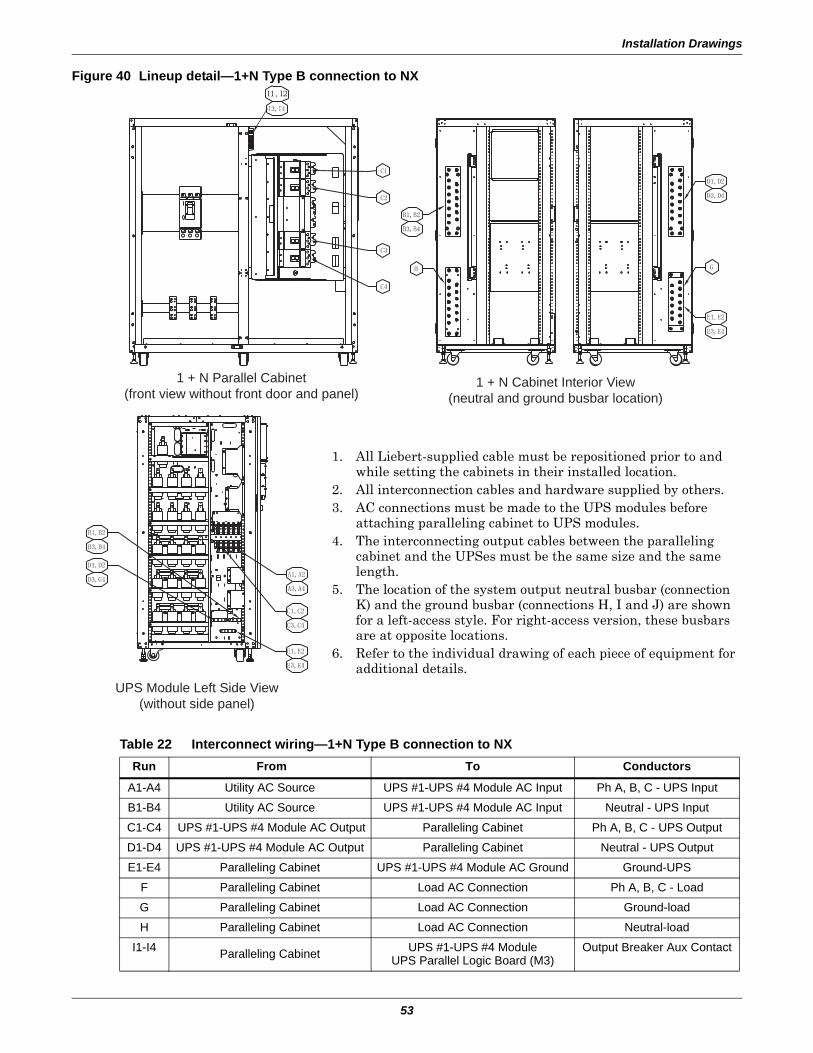
Installation Drawings
53
Figure 40 Lineup detail—1+N Type B connection to NX
Table 22 Interconnect wiring—1+N Type B connection to NXRun From To Conductors
A1-A4 Utility AC Source UPS #1-UPS #4 Module AC Input Ph A, B, C - UPS Input
B1-B4 Utility AC Source UPS #1-UPS #4 Module AC Input Neutral - UPS Input
C1-C4 UPS #1-UPS #4 Module AC Output Paralleling Cabinet Ph A, B, C - UPS Output
D1-D4 UPS #1-UPS #4 Module AC Output Paralleling Cabinet Neutral - UPS Output
E1-E4 Paralleling Cabinet UPS #1-UPS #4 Module AC Ground Ground-UPS
F Paralleling Cabinet Load AC Connection Ph A, B, C - Load
G Paralleling Cabinet Load AC Connection Ground-load
H Paralleling Cabinet Load AC Connection Neutral-load
I1-I4 Paralleling Cabinet UPS #1-UPS #4 ModuleUPS Parallel Logic Board (M3)
Output Breaker Aux Contact
1 + N Parallel Cabinet(front view without front door and panel)
1 + N Cabinet Interior View(neutral and ground busbar location)
UPS Module Left Side View(without side panel)
I1, I2
1. All Liebert-supplied cable must be repositioned prior to and while setting the cabinets in their installed location.
2. All interconnection cables and hardware supplied by others.3. AC connections must be made to the UPS modules before
attaching paralleling cabinet to UPS modules.4. The interconnecting output cables between the paralleling
cabinet and the UPSes must be the same size and the same length.
5. The location of the system output neutral busbar (connection K) and the ground busbar (connections H, I and J) are shown for a left-access style. For right-access version, these busbars are at opposite locations.
6. Refer to the individual drawing of each piece of equipment for additional details.

Installation Drawings
54
Figure 41 Lineup detail—1+N Type B1 connection to NX
Table 23 Interconnect wiring—1+N Type B1 connection to NXRun From To Conductors
A Utility AC Source Paralleling Cabinet Ph A, B, C - System InputB Utility AC Source Paralleling Cabinet Ground - System InputC Utility AC Source Paralleling Cabinet Neutral -system Input
D1-D4 Paralleling Cabinet UPS #1-UPS #4 Module AC Input Ph A, B, C - UPS InputE1-E4 Paralleling Cabinet UPS #1-UPS #4 Module AC Input Neutral - UPS InputF1-F4 UPS #1-UPS #4 Module AC Output Paralleling Cabinet Ph A, B, C - UPS OutputG1-G4 UPS #1-UPS #4 Module AC Output Paralleling Cabinet Neutral - UPS OutputH1-H4 Paralleling Cabinet UPS #1-UPS #4 Module AC Ground Ground-UPS
I Paralleling Cabinet Load AC Connection Ph A, B, C - LoadJ Paralleling Cabinet Load AC Connection Ground-loadK Paralleling Cabinet Load AC Connection Neutral-Load
L1-L4 Paralleling Cabinet UPS #1-UPS #4 ModuleUPS Parallel Logic Board (M3)
Output Breaker Aux Contact
M1-M4 Paralleling Cabinet UPS #1-UPS #4 ModuleUPS Parallel Logic Board (M3)
Rotary Switch Aux Contact
1 + N Parallel Cabinet(front view without front door and panel)
1 + N Cabinet Side View(without side panel or door)
1 + N Cabinet Interior View(neutral and ground busbar location)
UPS Module Left Side View(without side panel)
1. All Liebert-supplied cable must be repositioned prior to and while setting the cabinets in their installed location.
2. All interconnection cables and hardware supplied by others.3. AC connections must be made to the UPS modules before attaching
paralleling cabinet to UPS modules.4. The interconnecting input cables between the paralleling cabinet and
the UPSes must be the same size and the same length.5. The interconnecting output cables between the paralleling cabinet and
the UPSes must be the same size and the same length.6. The location of the system output neutral busbar (connection K) and
the ground busbar (connections H, I and J) are shown for a left-access style. For right-access version, these busbars are at opposite locations.
7. Refer to the individual drawing of each piece of equipment for additional details.
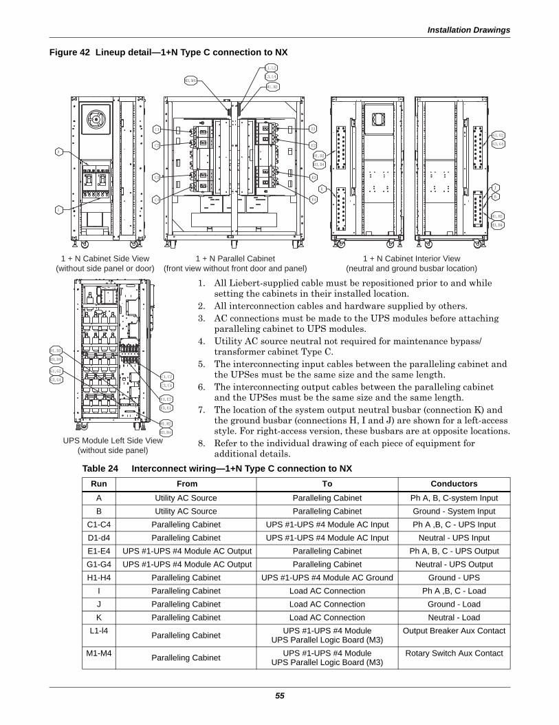
Installation Drawings
55
Figure 42 Lineup detail—1+N Type C connection to NX
Table 24 Interconnect wiring—1+N Type C connection to NXRun From To Conductors
A Utility AC Source Paralleling Cabinet Ph A, B, C-system InputB Utility AC Source Paralleling Cabinet Ground - System Input
C1-C4 Paralleling Cabinet UPS #1-UPS #4 Module AC Input Ph A ,B, C - UPS InputD1-d4 Paralleling Cabinet UPS #1-UPS #4 Module AC Input Neutral - UPS InputE1-E4 UPS #1-UPS #4 Module AC Output Paralleling Cabinet Ph A, B, C - UPS OutputG1-G4 UPS #1-UPS #4 Module AC Output Paralleling Cabinet Neutral - UPS OutputH1-H4 Paralleling Cabinet UPS #1-UPS #4 Module AC Ground Ground - UPS
I Paralleling Cabinet Load AC Connection Ph A ,B, C - LoadJ Paralleling Cabinet Load AC Connection Ground - LoadK Paralleling Cabinet Load AC Connection Neutral - Load
L1-l4 Paralleling Cabinet UPS #1-UPS #4 ModuleUPS Parallel Logic Board (M3)
Output Breaker Aux Contact
M1-M4 Paralleling Cabinet UPS #1-UPS #4 ModuleUPS Parallel Logic Board (M3)
Rotary Switch Aux Contact
1 + N Parallel Cabinet(front view without front door and panel)
1 + N Cabinet Side View(without side panel or door)
1 + N Cabinet Interior View(neutral and ground busbar location)
UPS Module Left Side View(without side panel)
1. All Liebert-supplied cable must be repositioned prior to and while setting the cabinets in their installed location.
2. All interconnection cables and hardware supplied by others.3. AC connections must be made to the UPS modules before attaching
paralleling cabinet to UPS modules.4. Utility AC source neutral not required for maintenance bypass/
transformer cabinet Type C.5. The interconnecting input cables between the paralleling cabinet and
the UPSes must be the same size and the same length.6. The interconnecting output cables between the paralleling cabinet
and the UPSes must be the same size and the same length.7. The location of the system output neutral busbar (connection K) and
the ground busbar (connections H, I and J) are shown for a left-access style. For right-access version, these busbars are at opposite locations.
8. Refer to the individual drawing of each piece of equipment for additional details.
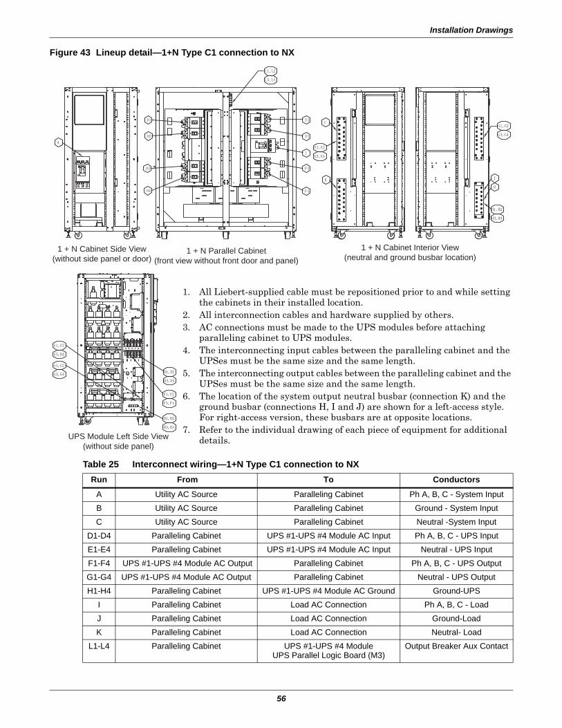
Installation Drawings
56
Figure 43 Lineup detail—1+N Type C1 connection to NX
Table 25 Interconnect wiring—1+N Type C1 connection to NXRun From To Conductors
A Utility AC Source Paralleling Cabinet Ph A, B, C - System Input
B Utility AC Source Paralleling Cabinet Ground - System Input
C Utility AC Source Paralleling Cabinet Neutral -System Input
D1-D4 Paralleling Cabinet UPS #1-UPS #4 Module AC Input Ph A, B, C - UPS Input
E1-E4 Paralleling Cabinet UPS #1-UPS #4 Module AC Input Neutral - UPS Input
F1-F4 UPS #1-UPS #4 Module AC Output Paralleling Cabinet Ph A, B, C - UPS Output
G1-G4 UPS #1-UPS #4 Module AC Output Paralleling Cabinet Neutral - UPS Output
H1-H4 Paralleling Cabinet UPS #1-UPS #4 Module AC Ground Ground-UPS
I Paralleling Cabinet Load AC Connection Ph A, B, C - Load
J Paralleling Cabinet Load AC Connection Ground-Load
K Paralleling Cabinet Load AC Connection Neutral- Load
L1-L4 Paralleling Cabinet UPS #1-UPS #4 ModuleUPS Parallel Logic Board (M3)
Output Breaker Aux Contact
1 + N Parallel Cabinet(front view without front door and panel)
1 + N Cabinet Side View(without side panel or door)
1 + N Cabinet Interior View(neutral and ground busbar location)
UPS Module Left Side View(without side panel)
1. All Liebert-supplied cable must be repositioned prior to and while setting the cabinets in their installed location.
2. All interconnection cables and hardware supplied by others.3. AC connections must be made to the UPS modules before attaching
paralleling cabinet to UPS modules.4. The interconnecting input cables between the paralleling cabinet and the
UPSes must be the same size and the same length.5. The interconnecting output cables between the paralleling cabinet and the
UPSes must be the same size and the same length.6. The location of the system output neutral busbar (connection K) and the
ground busbar (connections H, I and J) are shown for a left-access style. For right-access version, these busbars are at opposite locations.
7. Refer to the individual drawing of each piece of equipment for additional details.
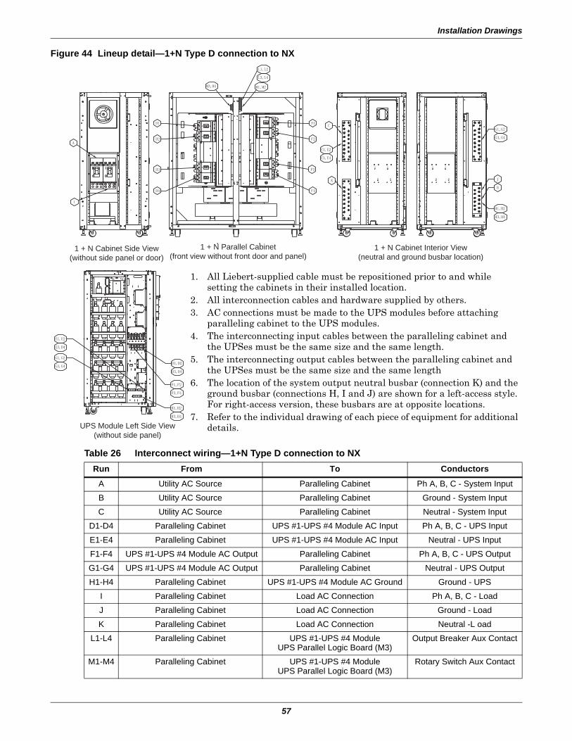
Installation Drawings
57
Figure 44 Lineup detail—1+N Type D connection to NX
Table 26 Interconnect wiring—1+N Type D connection to NXRun From To Conductors
A Utility AC Source Paralleling Cabinet Ph A, B, C - System Input
B Utility AC Source Paralleling Cabinet Ground - System Input
C Utility AC Source Paralleling Cabinet Neutral - System Input
D1-D4 Paralleling Cabinet UPS #1-UPS #4 Module AC Input Ph A, B, C - UPS Input
E1-E4 Paralleling Cabinet UPS #1-UPS #4 Module AC Input Neutral - UPS Input
F1-F4 UPS #1-UPS #4 Module AC Output Paralleling Cabinet Ph A, B, C - UPS Output
G1-G4 UPS #1-UPS #4 Module AC Output Paralleling Cabinet Neutral - UPS Output
H1-H4 Paralleling Cabinet UPS #1-UPS #4 Module AC Ground Ground - UPS
I Paralleling Cabinet Load AC Connection Ph A, B, C - Load
J Paralleling Cabinet Load AC Connection Ground - Load
K Paralleling Cabinet Load AC Connection Neutral -L oad
L1-L4 Paralleling Cabinet UPS #1-UPS #4 ModuleUPS Parallel Logic Board (M3)
Output Breaker Aux Contact
M1-M4 Paralleling Cabinet UPS #1-UPS #4 ModuleUPS Parallel Logic Board (M3)
Rotary Switch Aux Contact
1 + N Parallel Cabinet(front view without front door and panel)
1 + N Cabinet Side View(without side panel or door)
1 + N Cabinet Interior View(neutral and ground busbar location)
UPS Module Left Side View(without side panel)
1. All Liebert-supplied cable must be repositioned prior to and while setting the cabinets in their installed location.
2. All interconnection cables and hardware supplied by others.3. AC connections must be made to the UPS modules before attaching
paralleling cabinet to the UPS modules.4. The interconnecting input cables between the paralleling cabinet and
the UPSes must be the same size and the same length.5. The interconnecting output cables between the paralleling cabinet and
the UPSes must be the same size and the same length6. The location of the system output neutral busbar (connection K) and the
ground busbar (connections H, I and J) are shown for a left-access style. For right-access version, these busbars are at opposite locations.
7. Refer to the individual drawing of each piece of equipment for additional details.
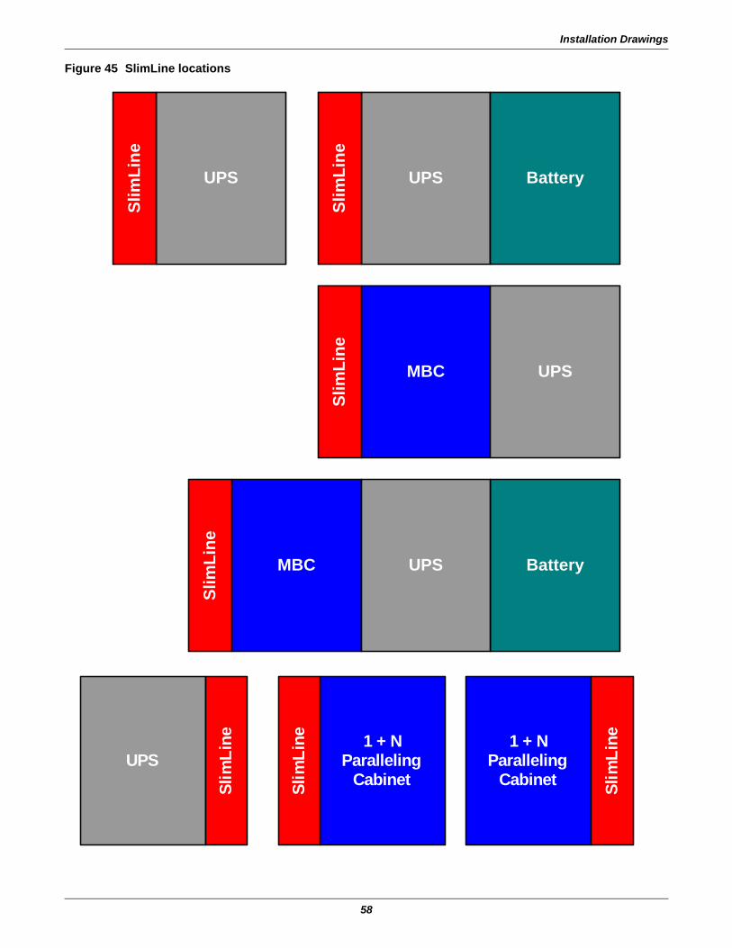
Installation Drawings
58
Figure 45 SlimLine locations
BatteryMBC UPS
Slim
Line
MBC UPS
Slim
Line
UPS Battery
Slim
Line
UPS
Slim
Line
UPS
Slim
Line 1 + N
ParallelingCabinetSl
imLi
ne 1 + NParalleling
Cabinet Slim
Line
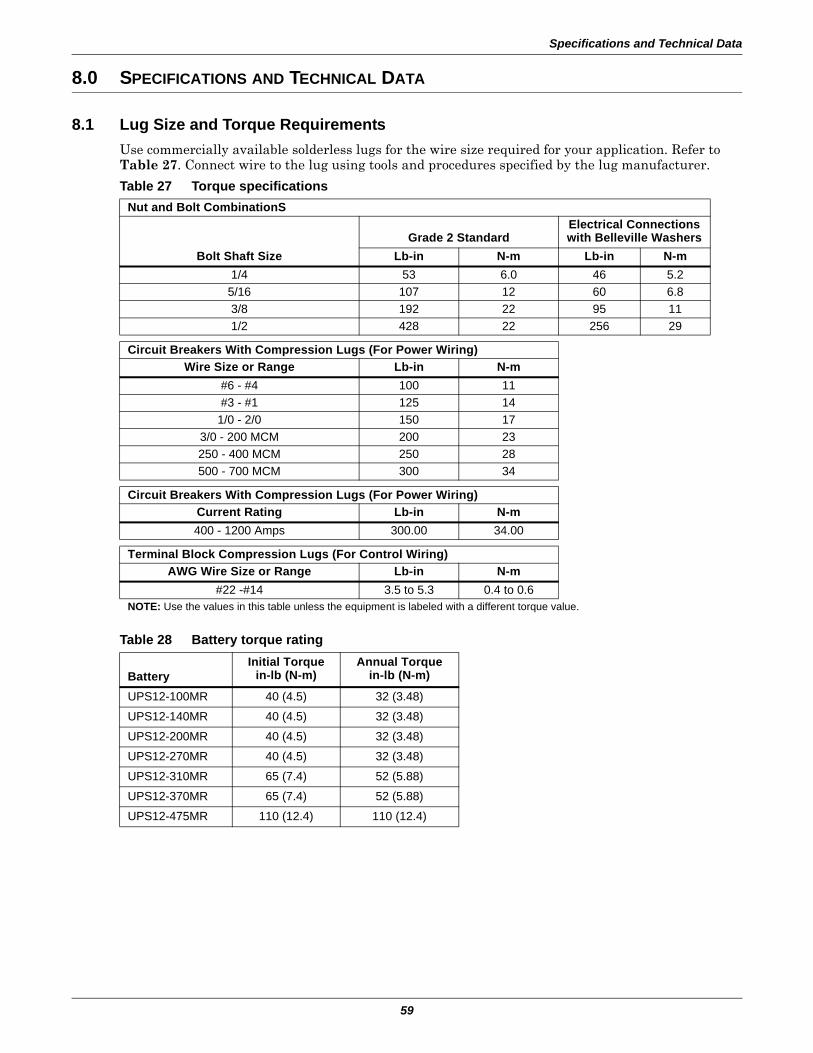
Specifications and Technical Data
59
8.0 SPECIFICATIONS AND TECHNICAL DATA
8.1 Lug Size and Torque RequirementsUse commercially available solderless lugs for the wire size required for your application. Refer to Table 27. Connect wire to the lug using tools and procedures specified by the lug manufacturer.
Table 27 Torque specificationsNut and Bolt CombinationS
Bolt Shaft SizeGrade 2 Standard
Electrical Connectionswith Belleville Washers
Lb-in N-m Lb-in N-m1/4 53 6.0 46 5.2
5/16 107 12 60 6.83/8 192 22 95 111/2 428 22 256 29
Circuit Breakers With Compression Lugs (For Power Wiring)Wire Size or Range Lb-in N-m
#6 - #4 100 11#3 - #1 125 14
1/0 - 2/0 150 173/0 - 200 MCM 200 23250 - 400 MCM 250 28500 - 700 MCM 300 34
Circuit Breakers With Compression Lugs (For Power Wiring)Current Rating Lb-in N-m400 - 1200 Amps 300.00 34.00
Terminal Block Compression Lugs (For Control Wiring)AWG Wire Size or Range Lb-in N-m
#22 -#14 3.5 to 5.3 0.4 to 0.6NOTE: Use the values in this table unless the equipment is labeled with a different torque value.
Table 28 Battery torque rating
BatteryInitial Torque
in-lb (N-m)Annual Torque
in-lb (N-m)
UPS12-100MR 40 (4.5) 32 (3.48)
UPS12-140MR 40 (4.5) 32 (3.48)
UPS12-200MR 40 (4.5) 32 (3.48)
UPS12-270MR 40 (4.5) 32 (3.48)
UPS12-310MR 65 (7.4) 52 (5.88)
UPS12-370MR 65 (7.4) 52 (5.88)
UPS12-475MR 110 (12.4) 110 (12.4)
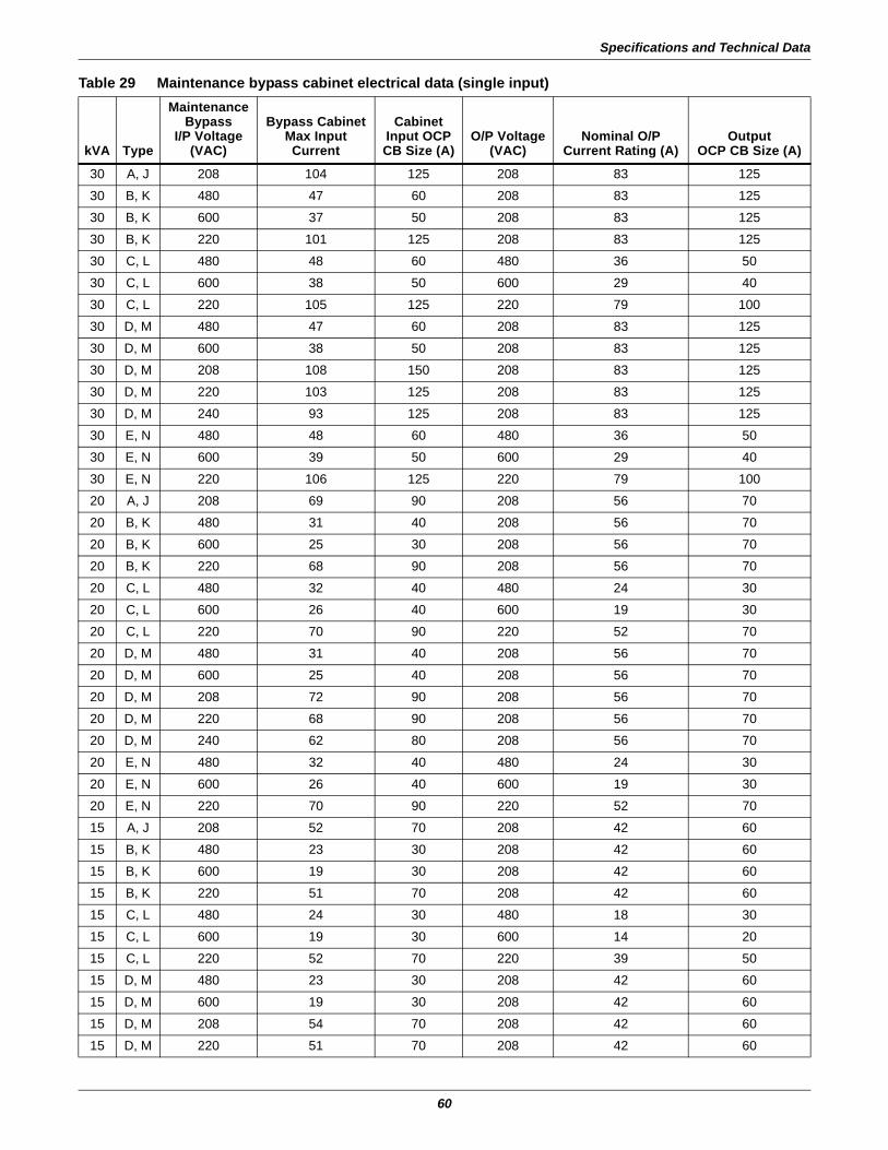
Specifications and Technical Data
60
Table 29 Maintenance bypass cabinet electrical data (single input)
kVA Type
MaintenanceBypass
I/P Voltage(VAC)
Bypass CabinetMax InputCurrent
CabinetInput OCPCB Size (A)
O/P Voltage(VAC)
Nominal O/PCurrent Rating (A)
OutputOCP CB Size (A)
30 A, J 208 104 125 208 83 125
30 B, K 480 47 60 208 83 125
30 B, K 600 37 50 208 83 125
30 B, K 220 101 125 208 83 125
30 C, L 480 48 60 480 36 50
30 C, L 600 38 50 600 29 40
30 C, L 220 105 125 220 79 100
30 D, M 480 47 60 208 83 125
30 D, M 600 38 50 208 83 125
30 D, M 208 108 150 208 83 125
30 D, M 220 103 125 208 83 125
30 D, M 240 93 125 208 83 125
30 E, N 480 48 60 480 36 50
30 E, N 600 39 50 600 29 40
30 E, N 220 106 125 220 79 100
20 A, J 208 69 90 208 56 70
20 B, K 480 31 40 208 56 70
20 B, K 600 25 30 208 56 70
20 B, K 220 68 90 208 56 70
20 C, L 480 32 40 480 24 30
20 C, L 600 26 40 600 19 30
20 C, L 220 70 90 220 52 70
20 D, M 480 31 40 208 56 70
20 D, M 600 25 40 208 56 70
20 D, M 208 72 90 208 56 70
20 D, M 220 68 90 208 56 70
20 D, M 240 62 80 208 56 70
20 E, N 480 32 40 480 24 30
20 E, N 600 26 40 600 19 30
20 E, N 220 70 90 220 52 70
15 A, J 208 52 70 208 42 60
15 B, K 480 23 30 208 42 60
15 B, K 600 19 30 208 42 60
15 B, K 220 51 70 208 42 60
15 C, L 480 24 30 480 18 30
15 C, L 600 19 30 600 14 20
15 C, L 220 52 70 220 39 50
15 D, M 480 23 30 208 42 60
15 D, M 600 19 30 208 42 60
15 D, M 208 54 70 208 42 60
15 D, M 220 51 70 208 42 60
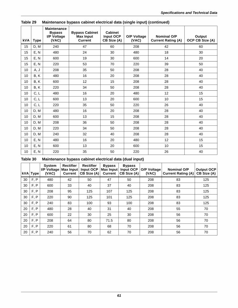
Specifications and Technical Data
61
15 D, M 240 47 60 208 42 60
15 E, N 480 24 30 480 18 30
15 E, N 600 19 30 600 14 20
15 E, N 220 53 70 220 39 50
10 A, J 208 35 50 208 28 40
10 B, K 480 16 20 208 28 40
10 B, K 600 12 15 208 28 40
10 B, K 220 34 50 208 28 40
10 C, L 480 16 20 480 12 15
10 C, L 600 13 20 600 10 15
10 C, L 220 35 50 220 26 40
10 D, M 480 16 20 208 28 40
10 D, M 600 13 15 208 28 40
10 D, M 208 36 50 208 28 40
10 D, M 220 34 50 208 28 40
10 D, M 240 32 40 208 28 40
10 E, N 480 16 20 480 12 15
10 E, N 600 13 20 600 10 15
10 E, N 220 35 50 220 26 40
Table 30 Maintenance bypass cabinet electrical data (dual input)
kVA Type
SystemI/P Voltage
(VAC)
RectifierMax InputCurrent
RectifierInput OCPCB Size (A)
Bypass Max InputCurrent
BypassInput OCPCB Size (A)
O/P Voltage(VAC)
Nominal O/PCurrent Rating (A)
Output OCPCB Size (A)
30 F, P 480 42 50 47 50 208 83 125
30 F, P 600 33 40 37 40 208 83 125
30 F, P 208 95 125 107 125 208 83 125
30 F, P 220 90 125 101 125 208 83 125
30 F, P 240 83 100 93 100 208 83 125
20 F, P 480 28 40 31 40 208 55 70
20 F, P 600 22 30 25 30 208 56 70
20 F, P 208 64 80 71.5 80 208 56 70
20 F, P 220 61 80 68 70 208 56 70
20 F, P 240 56 70 62 70 208 56 70
Table 29 Maintenance bypass cabinet electrical data (single input) (continued)
kVA Type
MaintenanceBypass
I/P Voltage(VAC)
Bypass CabinetMax InputCurrent
CabinetInput OCPCB Size (A)
O/P Voltage(VAC)
Nominal O/PCurrent Rating (A)
OutputOCP CB Size (A)
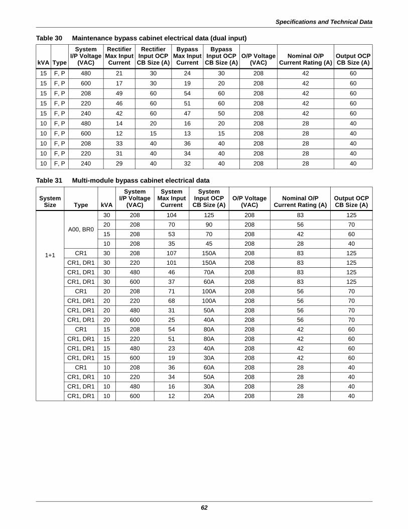
Specifications and Technical Data
62
15 F, P 480 21 30 24 30 208 42 60
15 F, P 600 17 30 19 20 208 42 60
15 F, P 208 49 60 54 60 208 42 60
15 F, P 220 46 60 51 60 208 42 60
15 F, P 240 42 60 47 50 208 42 60
10 F, P 480 14 20 16 20 208 28 40
10 F, P 600 12 15 13 15 208 28 40
10 F, P 208 33 40 36 40 208 28 40
10 F, P 220 31 40 34 40 208 28 40
10 F, P 240 29 40 32 40 208 28 40
Table 31 Multi-module bypass cabinet electrical data
SystemSize Type kVA
SystemI/P Voltage
(VAC)
SystemMax InputCurrent
SystemInput OCPCB Size (A)
O/P Voltage(VAC)
Nominal O/PCurrent Rating (A)
Output OCPCB Size (A)
1+1
A00, BR0
30 208 104 125 208 83 12520 208 70 90 208 56 7015 208 53 70 208 42 6010 208 35 45 208 28 40
CR1 30 208 107 150A 208 83 125CR1, DR1 30 220 101 150A 208 83 125CR1, DR1 30 480 46 70A 208 83 125CR1, DR1 30 600 37 60A 208 83 125
CR1 20 208 71 100A 208 56 70CR1, DR1 20 220 68 100A 208 56 70CR1, DR1 20 480 31 50A 208 56 70CR1, DR1 20 600 25 40A 208 56 70
CR1 15 208 54 80A 208 42 60CR1, DR1 15 220 51 80A 208 42 60CR1, DR1 15 480 23 40A 208 42 60CR1, DR1 15 600 19 30A 208 42 60
CR1 10 208 36 60A 208 28 40CR1, DR1 10 220 34 50A 208 28 40CR1, DR1 10 480 16 30A 208 28 40CR1, DR1 10 600 12 20A 208 28 40
Table 30 Maintenance bypass cabinet electrical data (dual input)
kVA Type
SystemI/P Voltage
(VAC)
RectifierMax InputCurrent
RectifierInput OCPCB Size (A)
Bypass Max InputCurrent
BypassInput OCPCB Size (A)
O/P Voltage(VAC)
Nominal O/PCurrent Rating (A)
Output OCPCB Size (A)
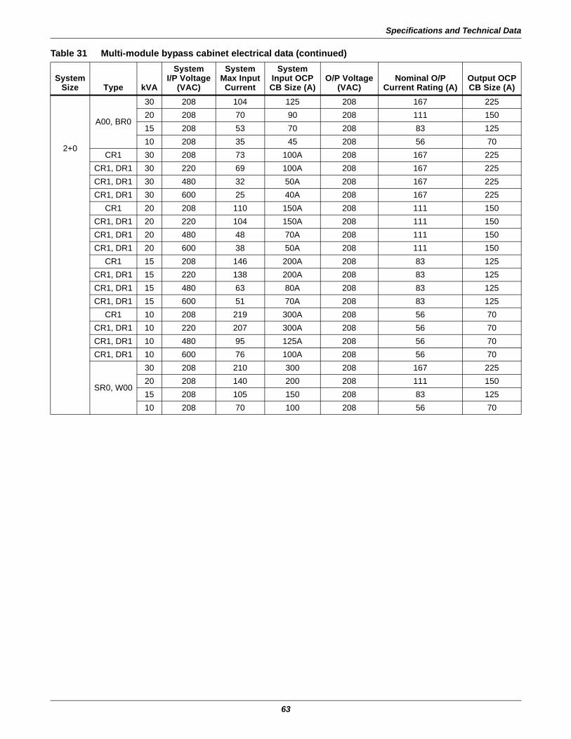
Specifications and Technical Data
63
2+0
A00, BR0
30 208 104 125 208 167 22520 208 70 90 208 111 15015 208 53 70 208 83 12510 208 35 45 208 56 70
CR1 30 208 73 100A 208 167 225CR1, DR1 30 220 69 100A 208 167 225CR1, DR1 30 480 32 50A 208 167 225CR1, DR1 30 600 25 40A 208 167 225
CR1 20 208 110 150A 208 111 150CR1, DR1 20 220 104 150A 208 111 150CR1, DR1 20 480 48 70A 208 111 150CR1, DR1 20 600 38 50A 208 111 150
CR1 15 208 146 200A 208 83 125CR1, DR1 15 220 138 200A 208 83 125CR1, DR1 15 480 63 80A 208 83 125CR1, DR1 15 600 51 70A 208 83 125
CR1 10 208 219 300A 208 56 70CR1, DR1 10 220 207 300A 208 56 70CR1, DR1 10 480 95 125A 208 56 70CR1, DR1 10 600 76 100A 208 56 70
SR0, W00
30 208 210 300 208 167 22520 208 140 200 208 111 15015 208 105 150 208 83 12510 208 70 100 208 56 70
Table 31 Multi-module bypass cabinet electrical data (continued)
SystemSize Type kVA
SystemI/P Voltage
(VAC)
SystemMax InputCurrent
SystemInput OCPCB Size (A)
O/P Voltage(VAC)
Nominal O/PCurrent Rating (A)
Output OCPCB Size (A)
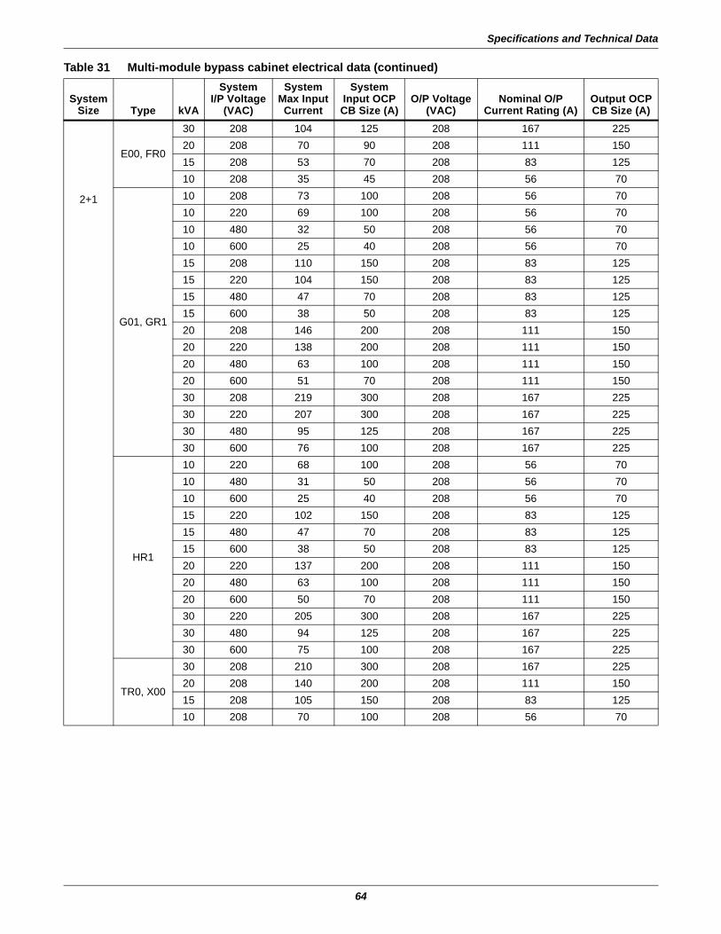
Specifications and Technical Data
64
2+1
E00, FR0
30 208 104 125 208 167 22520 208 70 90 208 111 15015 208 53 70 208 83 12510 208 35 45 208 56 70
G01, GR1
10 208 73 100 208 56 7010 220 69 100 208 56 7010 480 32 50 208 56 7010 600 25 40 208 56 7015 208 110 150 208 83 12515 220 104 150 208 83 12515 480 47 70 208 83 12515 600 38 50 208 83 12520 208 146 200 208 111 15020 220 138 200 208 111 15020 480 63 100 208 111 15020 600 51 70 208 111 15030 208 219 300 208 167 22530 220 207 300 208 167 22530 480 95 125 208 167 22530 600 76 100 208 167 225
HR1
10 220 68 100 208 56 7010 480 31 50 208 56 7010 600 25 40 208 56 7015 220 102 150 208 83 12515 480 47 70 208 83 12515 600 38 50 208 83 12520 220 137 200 208 111 15020 480 63 100 208 111 15020 600 50 70 208 111 15030 220 205 300 208 167 22530 480 94 125 208 167 22530 600 75 100 208 167 225
TR0, X00
30 208 210 300 208 167 22520 208 140 200 208 111 15015 208 105 150 208 83 12510 208 70 100 208 56 70
Table 31 Multi-module bypass cabinet electrical data (continued)
SystemSize Type kVA
SystemI/P Voltage
(VAC)
SystemMax InputCurrent
SystemInput OCPCB Size (A)
O/P Voltage(VAC)
Nominal O/PCurrent Rating (A)
Output OCPCB Size (A)

Specifications and Technical Data
65
3+0
E00, FR0
30 208 104 125 208 250 40020 208 70 90 208 167 22515 208 53 70 208 125 20010 208 35 45 208 83 125
G01, GR1
10 208 110 150 208 83 12510 220 104 150 208 83 12510 480 47 60 208 83 12510 600 38 50 208 83 12515 208 164 225 208 125 20015 220 155 200 208 125 20015 480 71 90 208 125 20015 600 57 80 208 125 20020 208 219 300 208 167 22520 220 207 300 208 167 22520 480 95 125 208 167 22520 600 76 100 208 167 22530 208 329 500 208 250 40030 220 311 400 208 250 40030 480 142 200 208 250 40030 600 114 150 208 250 400
HR1
10 220 102 150 208 83 12510 480 47 60 208 83 12510 600 38 50 208 83 12515 220 154 200 208 125 20015 480 70 90 208 125 20015 600 56 80 208 125 20020 220 205 300 208 167 22520 480 94 125 208 167 22520 600 75 100 208 167 22530 220 307 400 208 250 40030 480 141 200 208 250 40030 600 113 150 208 250 400
TR0, X00
30 208 315 400 208 250 40020 208 210 300 208 167 22515 208 158 200 208 125 20010 208 105 150 208 83 125
Table 31 Multi-module bypass cabinet electrical data (continued)
SystemSize Type kVA
SystemI/P Voltage
(VAC)
SystemMax InputCurrent
SystemInput OCPCB Size (A)
O/P Voltage(VAC)
Nominal O/PCurrent Rating (A)
Output OCPCB Size (A)
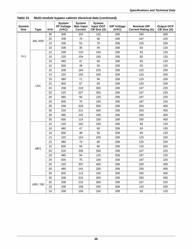
Specifications and Technical Data
66
3+1
J00, KR0
30 208 104 125 208 250 40020 208 70 90 208 167 22515 208 53 70 208 125 20010 208 35 45 208 83 125
LR1
10 208 110 150 208 83 12510 220 104 150 208 83 12510 480 47 60 208 83 12510 600 38 50 208 83 12515 208 164 225 208 125 20015 220 155 200 208 125 20015 480 71 90 208 125 20015 600 57 80 208 125 20020 208 219 300 208 167 22520 220 207 300 208 167 22520 480 95 125 208 167 22520 600 76 100 208 167 22530 208 329 500 208 250 40030 220 311 400 208 250 40030 480 142 200 208 250 40030 600 114 150 208 250 400
MR1
10 220 102 150 208 83 12510 480 47 60 208 83 12510 600 38 50 208 83 12515 220 154 200 208 125 20015 480 70 90 208 125 20015 600 56 80 208 125 20020 220 205 300 208 167 22520 480 94 125 208 167 22520 600 75 100 208 167 22530 220 307 400 208 250 40030 480 141 200 208 250 40030 600 113 150 208 250 400
UR0, Y00
30 208 315 400 208 250 40020 208 210 300 208 167 22515 208 158 200 208 125 20010 208 105 150 208 83 125
Table 31 Multi-module bypass cabinet electrical data (continued)
SystemSize Type kVA
SystemI/P Voltage
(VAC)
SystemMax InputCurrent
SystemInput OCPCB Size (A)
O/P Voltage(VAC)
Nominal O/PCurrent Rating (A)
Output OCPCB Size (A)
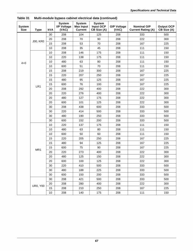
Specifications and Technical Data
67
4+0
J00, KR0
30 208 104 125 208 333 50020 208 70 90 208 222 30015 208 53 70 208 167 22510 208 35 45 208 111 150
LR1
10 208 146 175 208 111 15010 220 138 175 208 111 15010 480 63 80 208 111 15010 600 51 70 208 111 15015 208 219 300 208 167 22515 220 207 250 208 167 22515 480 95 125 208 167 22515 600 76 100 208 167 22520 208 292 400 208 222 30020 220 276 400 208 222 30020 480 127 175 208 222 30020 600 101 125 208 222 30030 208 438 600 208 333 50030 220 414 500 208 333 50030 480 190 250 208 333 50030 600 152 200 208 333 500
MR1
10 220 137 175 208 111 15010 480 63 80 208 111 15010 600 50 60 208 111 15015 220 205 250 208 167 22515 480 94 125 208 167 22515 600 75 90 208 167 22520 220 273 400 208 222 30020 480 125 150 208 222 30020 600 100 125 208 222 30030 220 410 500 208 333 50030 480 188 225 208 333 50030 600 150 200 208 333 500
UR0, Y00
30 208 421 500 208 333 50020 208 280 400 208 222 30015 208 210 250 208 167 22510 208 140 175 208 111 150
Table 31 Multi-module bypass cabinet electrical data (continued)
SystemSize Type kVA
SystemI/P Voltage
(VAC)
SystemMax InputCurrent
SystemInput OCPCB Size (A)
O/P Voltage(VAC)
Nominal O/PCurrent Rating (A)
Output OCPCB Size (A)
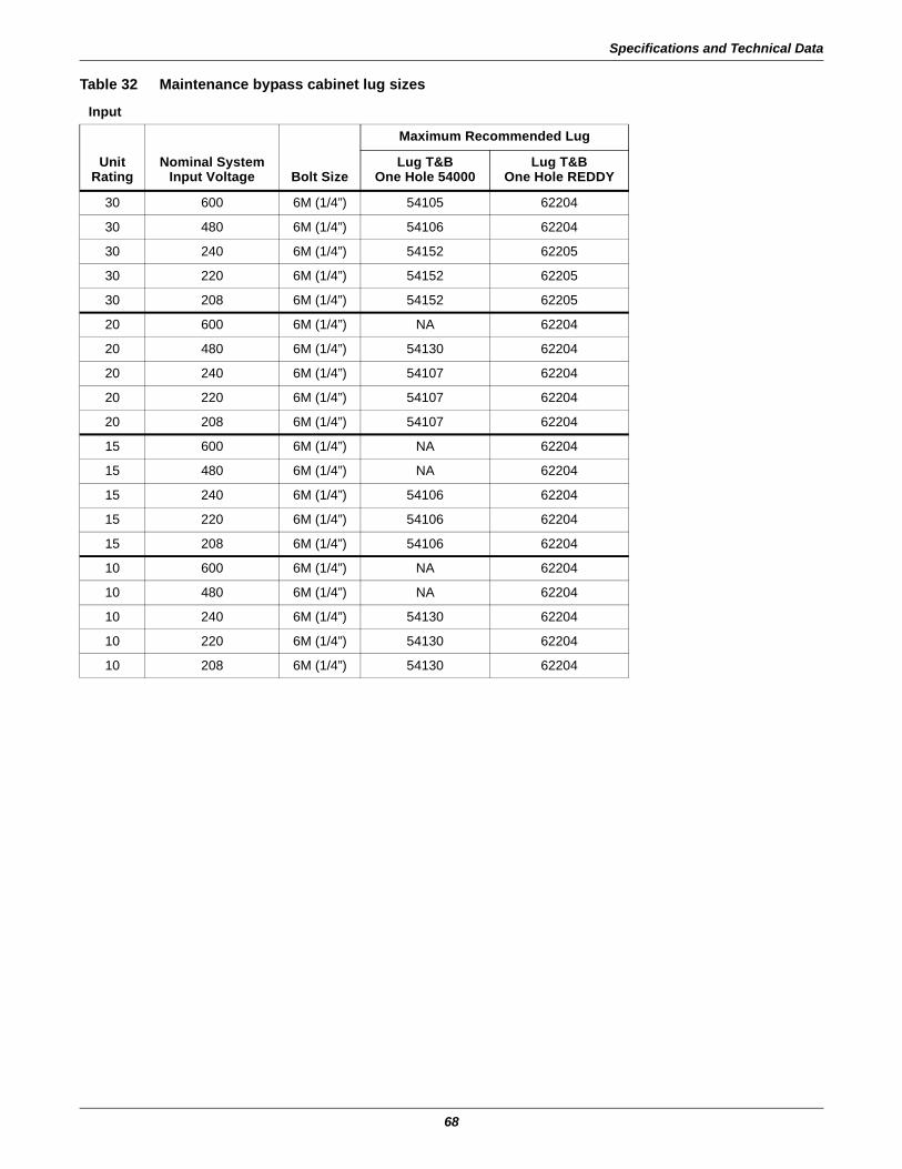
Specifications and Technical Data
68
Table 32 Maintenance bypass cabinet lug sizes
Input
UnitRating
Nominal SystemInput Voltage Bolt Size
Maximum Recommended Lug
Lug T&BOne Hole 54000
Lug T&BOne Hole REDDY
30 600 6M (1/4”) 54105 62204
30 480 6M (1/4”) 54106 62204
30 240 6M (1/4”) 54152 62205
30 220 6M (1/4”) 54152 62205
30 208 6M (1/4”) 54152 62205
20 600 6M (1/4”) NA 62204
20 480 6M (1/4”) 54130 62204
20 240 6M (1/4”) 54107 62204
20 220 6M (1/4”) 54107 62204
20 208 6M (1/4”) 54107 62204
15 600 6M (1/4”) NA 62204
15 480 6M (1/4”) NA 62204
15 240 6M (1/4”) 54106 62204
15 220 6M (1/4”) 54106 62204
15 208 6M (1/4”) 54106 62204
10 600 6M (1/4”) NA 62204
10 480 6M (1/4”) NA 62204
10 240 6M (1/4”) 54130 62204
10 220 6M (1/4”) 54130 62204
10 208 6M (1/4”) 54130 62204

Specifications and Technical Data
69
Output
UnitRating
Nominal SystemOutput Voltage Bolt Size
Maximum Recommended Lug
Lug T&BOne Hole 54000
Lug T&BOne Hole REDDY
30 600 6M (1/4”) 54130 62204
30 480 6M (1/4”) 54106 62204
30 240 6M (1/4”) 54108 62205
30 220 6M (1/4”) 54108 62205
30 208 6M (1/4”) 54108 62205
20 600 6M (1/4”) NA 62204
20 480 6M (1/4”) 54130 62204
20 240 6M (1/4”) 54106 62204
20 220 6M (1/4”) 54106 62204
20 208 6M (1/4”) 54106 62204
15 600 6M (1/4”) NA 62204
15 480 6M (1/4”) NA 62204
15 240 6M (1/4”) 54106 62204
15 220 6M (1/4”) 54106 62204
15 208 6M (1/4”) 54106 62204
10 600 6M (1/4”) NA 62204
10 480 6M (1/4”) NA 62204
10 240 6M (1/4”) 54130 62204
10 220 6M (1/4”) 54130 62204
10 208 6M (1/4”) 54130 62204
Table 33 Battery cabinet physical characteristicsBattery Cabinet
TypeDimensions
WxDxH in. (mm)Net Weight WithoutBatteries, lb. (kg)
Short Narrow 27.2x31.4x63(690x825x1600)
551(250)
Short Wide 58.5x31.4x63(1488x825x1600)
889(400)
Table 34 Maintenance Bypass Cabinet weights
UPSRating
Maintenance Bypass Cabinet Style, lb. (kg)
A B C D E F J K L M N P
10kVA 408 (185)
545 (247)
675 (306)
602 (273)
732 (332)
630 (286)
403 (183)
540 (245)
670 (304)
597 (271)
728 (330)
630 (286)
15kVA 408 (185)
567 (257)
728 (330)
659 (299)
822 (373)
680 (308)
403 (183)
562 (255)
723 (328)
655 (297)
818 (371)
680 (308)
20kVA 408 (185)
646 (293)
842 (382)
739 (335)
935 (424)
750 (340)
403 (183)
642 (291)
838 (380)
734 (333)
930 (422)
750 (340)
30kVA 408 (185)
694 (315)
893 (405)
807 (366)
1027 (466)
840 (381)
403 (183)
690 (313)
888 (403)
802 (364)
1023 (464)
840 (381)
Table 32 Maintenance bypass cabinet lug sizes (continued)
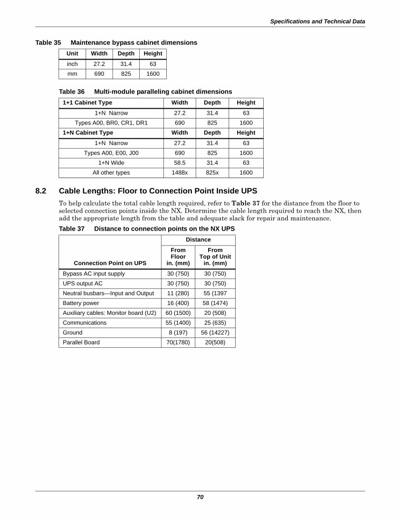
Specifications and Technical Data
70
8.2 Cable Lengths: Floor to Connection Point Inside UPSTo help calculate the total cable length required, refer to Table 37 for the distance from the floor to selected connection points inside the NX. Determine the cable length required to reach the NX, then add the appropriate length from the table and adequate slack for repair and maintenance.
Table 35 Maintenance bypass cabinet dimensionsUnit Width Depth Height
inch 27.2 31.4 63
mm 690 825 1600
Table 36 Multi-module paralleling cabinet dimensions1+1 Cabinet Type Width Depth Height
1+N Narrow 27.2 31.4 63
Types A00, BR0, CR1, DR1 690 825 1600
1+N Cabinet Type Width Depth Height
1+N Narrow 27.2 31.4 63
Types A00, E00, J00 690 825 1600
1+N Wide 58.5 31.4 63
All other types 1488x 825x 1600
Table 37 Distance to connection points on the NX UPS
Connection Point on UPS
Distance
FromFloor
in. (mm)
FromTop of Unit
in. (mm)
Bypass AC input supply 30 (750) 30 (750)
UPS output AC 30 (750) 30 (750)
Neutral busbars—Input and Output 11 (280) 55 (1397
Battery power 16 (400) 58 (1474)
Auxiliary cables: Monitor board (U2) 60 (1500) 20 (508)
Communications 55 (1400) 25 (635)
Ground 8 (197) 56 (14227)
Parallel Board 70(1780) 20(508)

Specifications and Technical Data
71
NOTES

Specifications and Technical Data
72


EmersonNetworkPower.com
Ensuring The High Availability0f Mission-Critical Data And Applications.
Emerson Network Power, the global leader in enabling business-criticalcontinuity, ensures network resiliency and adaptability througha family of technologies—including Liebert power and coolingtechnologies—that protect and support business-critical systems.Liebert solutions employ an adaptive architecture that respondsto changes in criticality, density and capacity. Enterprises benefitfrom greater IT system availability, operational flexibility andreduced capital equipment and operating costs.
While every precaution has been taken to ensure the accuracyand completeness of this literature, Liebert Corporation assumes noresponsibility and disclaims all liability for damages resulting from use ofthis information or for any errors or omissions.© 2006 Liebert CorporationAll rights reserved throughout the world. Specifications subject to changewithout notice.® Liebert and the Liebert logo are registered trademarks of LiebertCorporation. All names referred to are trademarksor registered trademarks of their respective owners.
Technical Support / ServiceWeb Site
www.liebert.comMonitoring
Outside the US: 614-841-6755Single-Phase UPS
Outside the US: 614-841-6755Three-Phase UPS
Environmental Systems800-543-2778
Outside the United States614-888-0246
LocationsUnited States
1050 Dearborn DriveP.O. Box 29186
Columbus, OH 43229Europe
Via Leonardo Da Vinci 8Zona Industriale Tognana
35028 Piove Di Sacco (PD) Italy+39 049 9719 111
Fax: +39 049 5841 257Asia
7/F, Dah Sing Financial Centre108 Gloucester Road, Wanchai
Hong Kong852 2572220
Fax: 852 28029250
Emerson Network Power. The global leader in enabling Business-Critical Continuity™.
Business-Critical Continuity, Emerson Network Power and the Emerson Network Power logo are trademarks and service marks of Emerson Electric Co.
©2006 Emerson Electric Co.
Monitoring
AC Power
Connectivity
DC Power
Embedded ComputingEmbedded Power Power Switching & Controls
Precision Cooling
ServicesRacks & Integrated CabinetsOutside Plant
Surge Protection
SL-25215_REV6_11-06