Uplink Timing Control(ERAN8.1_02)
42
eRAN Uplink Timing Control Feature Parameter Description Issue 02 Date 2015-11-03 HUAWEI TECHNOLOGIES CO., LTD.
-
Upload
muhammad-abdur-razzaqe -
Category
Documents
-
view
89 -
download
8
description
UTC LTE
Transcript of Uplink Timing Control(ERAN8.1_02)

eRAN
Uplink Timing Control FeatureParameter Description
Issue 02
Date 2015-11-03
HUAWEI TECHNOLOGIES CO., LTD.
Copyright © Huawei Technologies Co., Ltd. 2015. All rights reserved.No part of this document may be reproduced or transmitted in any form or by any means without prior writtenconsent of Huawei Technologies Co., Ltd. Trademarks and Permissions
and other Huawei trademarks are trademarks of Huawei Technologies Co., Ltd.All other trademarks and trade names mentioned in this document are the property of their respectiveholders. NoticeThe purchased products, services and features are stipulated by the contract made between Huawei and thecustomer. All or part of the products, services and features described in this document may not be within thepurchase scope or the usage scope. Unless otherwise specified in the contract, all statements, information,and recommendations in this document are provided "AS IS" without warranties, guarantees orrepresentations of any kind, either express or implied.
The information in this document is subject to change without notice. Every effort has been made in thepreparation of this document to ensure accuracy of the contents, but all statements, information, andrecommendations in this document do not constitute a warranty of any kind, express or implied.
Huawei Technologies Co., Ltd.Address: Huawei Industrial Base
Bantian, LonggangShenzhen 518129People's Republic of China
Website: http://www.huawei.com
Email: [email protected]
Issue 02 (2015-11-03) Huawei Proprietary and ConfidentialCopyright © Huawei Technologies Co., Ltd.
i

Contents
1 About The Document................................................................................................................... 11.1 Scope.............................................................................................................................................................................. 11.2 Intended Audience..........................................................................................................................................................11.3 Change History............................................................................................................................................................... 11.4 Differences Between eNodeB Types.............................................................................................................................. 2
2 Overview......................................................................................................................................... 32.1 Introduction.................................................................................................................................................................... 32.2 Benefits...........................................................................................................................................................................3
3 Technical Description...................................................................................................................43.1 Uplink Timing Control During RA................................................................................................................................ 63.2 Uplink Timing Control After RA................................................................................................................................... 73.3 Timers............................................................................................................................................................................. 93.3.1 Uplink Time Alignment Timer.................................................................................................................................... 93.3.2 Uplink Synchronization Timer.................................................................................................................................. 123.3.3 UE Inactivity Timer................................................................................................................................................... 12
4 Related Features...........................................................................................................................144.1 LBFD-070101 Uplink Timing Based on PUCCH........................................................................................................14
5 Network Impact........................................................................................................................... 165.1 LBFD-070101 Uplink Timing Based on PUCCH........................................................................................................16
6 Engineering Guidelines............................................................................................................. 176.1 When to Use LAOFD-001001 and LAOFD-001002................................................................................................... 176.2 Required Information................................................................................................................................................... 176.3 Planning........................................................................................................................................................................ 176.4 Deployment.................................................................................................................................................................. 176.4.1 Requirements............................................................................................................................................................. 176.4.2 Data Preparation........................................................................................................................................................ 186.4.3 Initial Configuration.................................................................................................................................................. 206.4.4 Activation Observation..............................................................................................................................................236.4.5 Deactivation...............................................................................................................................................................236.4.6 Reconfiguration......................................................................................................................................................... 266.5 Performance Monitoring...............................................................................................................................................26
eRANUplink Timing Control Feature Parameter Description Contents
Issue 02 (2015-11-03) Huawei Proprietary and ConfidentialCopyright © Huawei Technologies Co., Ltd.
ii
6.6 Parameter Optimization................................................................................................................................................276.7 Troubleshooting............................................................................................................................................................ 28
7 Parameters.....................................................................................................................................29
8 Counters........................................................................................................................................ 35
9 Glossary.........................................................................................................................................37
10 Reference Documents............................................................................................................... 38
eRANUplink Timing Control Feature Parameter Description Contents
Issue 02 (2015-11-03) Huawei Proprietary and ConfidentialCopyright © Huawei Technologies Co., Ltd.
iii

1 About The Document
1.1 ScopeThis document describes LBFD-070101 Uplink Timing Based on PUCCH and uplink timingcontrol, including their technical principles, related features, network impact, and engineeringguidelines.
Any managed objects (MOs), parameters, alarms, or counters described herein correspond tothe software release delivered with this document. Any future updates will be described in theproduct documentation delivered with future software releases.
This document applies only to LTE FDD. Any "LTE" in this document refers to LTE FDD,and "eNodeB" refers to LTE FDD eNodeB.
This document applies to the following types of eNodeBs.
eNodeB Type Model
Macro 3900 series eNodeB
Micro BTS3202E
LampSite DBS3900 LampSite
1.2 Intended AudienceThis document is intended for personnel who:
l Need to understand the features described hereinl Work with Huawei products
1.3 Change HistoryThis section provides information about the changes in different document versions. There aretwo types of changes:
eRANUplink Timing Control Feature Parameter Description 1 About The Document
Issue 02 (2015-11-03) Huawei Proprietary and ConfidentialCopyright © Huawei Technologies Co., Ltd.
1

l Feature change
Changes in features and parameters of a specified version as well as the affected entities
l Editorial change
Changes in wording or addition of information and any related parameters affected byeditorial changes. Editorial change does not specify the affected entities.
eRAN8.1 02 (2015-11-03)This issue includes the following changes.
ChangeType
Change Description ParameterChange
Affected Entity
Featurechange
None None N/A
Editorialchange
Added the actual TA command sendingperiod when the TimeAlignmentTim-er.TACmdSendPeriod parameter is setto. INVALID. For details, see 4 in 3.2Uplink Timing Control After RA.
None -
Revised descriptions in the document. None -
eRAN8.1 01 (2015-03-23)This issue does not include any changes.
eRAN8.1 Draft A (2015-01-15)Compared with Issue 04 (2014-09-30) of eRAN7.0, Draft A (2015-01-15) of eRAN8.1 doesnot include any changes.
1.4 Differences Between eNodeB TypesThe features described in this document are implemented in the same way on macro, micro,and LampSite eNodeBs.
eRANUplink Timing Control Feature Parameter Description 1 About The Document
Issue 02 (2015-11-03) Huawei Proprietary and ConfidentialCopyright © Huawei Technologies Co., Ltd.
2

2 Overview
2.1 IntroductionDuring uplink timing control, the eNodeB calculates the timing offset after measuring uplinksignals received from a UE. Based on the results of this calculation, the eNodeB then convertsthe timing offset into the Timing Advance Command and sends the command to the UE. TheUE uses this information to adjust the time to transmit uplink signals. The entire processensures time synchronization between the UE and the eNodeB, as shown in Figure 2-1.
Figure 2-1 Uplink timing control
2.2 BenefitsWith uplink timing control, the eNodeB adjusts the time of each UE to transmit uplink signalsso that uplink signals from different UEs simultaneously reach the eNodeB. This ensuresorthogonality of data transmitted from different UEs, mitigates intra-cell interference, andensures demodulation performance on data transmitted by UEs.
eRANUplink Timing Control Feature Parameter Description 2 Overview
Issue 02 (2015-11-03) Huawei Proprietary and ConfidentialCopyright © Huawei Technologies Co., Ltd.
3

3 Technical Description
Uplink timing control can be categorized into uplink timing control during random access(RA) and uplink timing control after RA, as shown in Figure 3-1.l Uplink timing control during RA
Non-synchronized UEs (including UEs that are newly powered on or handed over to thecell, UEs in RRC_IDLE mode, and out-of-synchronized UEs) establish or restore uplinksynchronization based on RA, and then enter the synchronization state. For details, see3.1 Uplink Timing Control During RA.
l Uplink timing control after RAA synchronized UE maintains the synchronization state based on periodic uplink timingadjustment. For details, see 3.2 Uplink Timing Control After RA.When a UE is in the synchronization state, timers, including the uplink time alignmenttimer, uplink synchronization timer, and UE inactivity timer, maintain and manage thesynchronization state of the UE. For details about working principles and settings ofthese timers, see 3.3.1 Uplink Time Alignment Timer, 3.3.2 Uplink SynchronizationTimer, and 3.3.3 UE Inactivity Timer.– If the uplink time alignment timer expires, an uplink-synchronized UE enters the
out-of-synchronization state.– If the uplink synchronization timer expires, this causes the uplink time alignment
timer to expire, and then an uplink-synchronized UE enters the out-of-synchronization state.
– If the UE inactivity timer expires, an uplink-synchronized UE enters theRRC_IDLE mode.
A non-synchronized UE enters the synchronization state by initiating the RA procedure.
eRANUplink Timing Control Feature Parameter Description 3 Technical Description
Issue 02 (2015-11-03) Huawei Proprietary and ConfidentialCopyright © Huawei Technologies Co., Ltd.
4
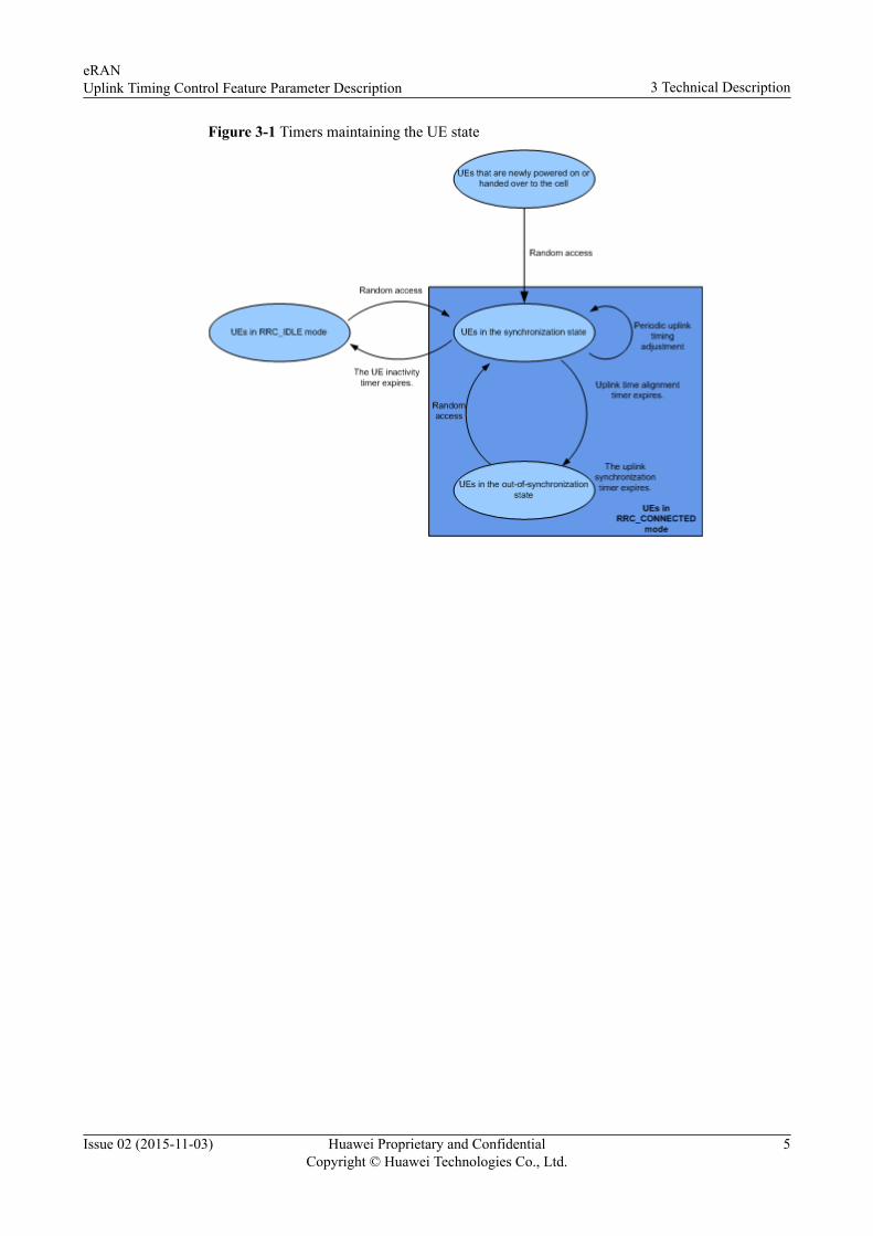
Figure 3-1 Timers maintaining the UE state
eRANUplink Timing Control Feature Parameter Description 3 Technical Description
Issue 02 (2015-11-03) Huawei Proprietary and ConfidentialCopyright © Huawei Technologies Co., Ltd.
5

3.1 Uplink Timing Control During RARA is classified into contention-based RA and non-contention-based RA.
A UE achieves uplink synchronization with the eNodeB based on uplink timing during RA.Figure 3-2 outlines the procedure for uplink timing control during RA.
Figure 3-2 Uplink timing control during RA
1. A UE sends a Random Access Preamble message to the eNodeB.
2. The eNodeB measures the timing offset on the UE side based on the received RandomAccess Preamble message.
3. The eNodeB converts the measured timing offset into a Timing Advance Command.
4. The eNodeB sends the UE the Timing Advance Command, which is contained in theRandom Access Response message.
5. Upon receiving the Timing Advance Command, the UE adjusts the time to transmituplink signals. For details about timing adjustment, see section 4.2.3 "Transmissiontiming adjustments" in 3GPP TS 36.213 V10.10.0.
eRANUplink Timing Control Feature Parameter Description 3 Technical Description
Issue 02 (2015-11-03) Huawei Proprietary and ConfidentialCopyright © Huawei Technologies Co., Ltd.
6

3.2 Uplink Timing Control After RAAfter RA is performed, an uplink-synchronized UE maintains uplink synchronization with theeNodeB based on periodic uplink timing adjustment. Figure 3-3 shows the procedure forperiodic uplink timing adjustment.
Figure 3-3 Periodic uplink timing adjustment
1. The eNodeB allocates uplink resources to a UE, and the UE transmits uplink signals.Resources allocated to the UE may include sounding reference signal (SRS) resources,demodulation reference signal (DMRS) for the physical uplink shared channel (PUSCH),or channel quality indicator (CQI) in physical uplink control channel (PUCCH).
2. The eNodeB receives the transmitted uplink signals and measures the timing offset of theUE.The timing offset can be measured based on the allocated SRS resources, DMRS forPUSCH, or CQI in PUCCH. The TimeAlignmentTimer.TimingMeasMode parameterspecifies the method for measuring uplink timing offsets.– When this parameter is set to INVALID(Invalid Timing Measurement Mode):
n If the eNodeB has already allocated SRS resources to a UE, the eNodeBmeasures the timing offset of the UE based on the SRS resources.
n If the eNodeB has not allocated SRS resources to a UE, the eNodeB measuresthe timing offset of the UE based on the DMRS for PUSCH. If the UE doesnot have any PUSCH resources, the eNodeB allocates PUSCH resources to theUE and then measures the timing offset based on the DMRS for PUSCH.
– When this parameter is set to ALLMEASMODE(All Timing MeasurementMode):
eRANUplink Timing Control Feature Parameter Description 3 Technical Description
Issue 02 (2015-11-03) Huawei Proprietary and ConfidentialCopyright © Huawei Technologies Co., Ltd.
7

n If the eNodeB has already allocated SRS resources to a UE, the eNodeBmeasures the timing offset of the UE based on the SRS resources. If the UEhas PUSCH resources, the eNodeB measures the timing offset of the UE basedon the SRS and DMRS for PUSCH, where the timing offset measured basedon the DMRS for PUSCH is preferentially used.
n If the eNodeB has not allocated SRS resources to a UE, the eNodeB measuresthe timing offset of the UE based on the CQI in PUCCH. If the UE hasPUSCH resources, the eNodeB measures the timing offset of the UE based onthe CQI in PUCCH and DMRS for PUSCH, where the timing offset measuredbased on the DMRS for PUSCH is preferentially used.
NOTE
The eNodeB measures the timing offset of the UE based on the CQI in PUCCH onlywhen the eNodeB has allocated periodic CQIs to the UE. The eNodeB allocatesperiodic CQIs to UEs that are newly powered on, UEs that are newly handed over tothe cell, and UEs in idle mode. The eNodeB reconfigures periodic CQIs forasynchronized UEs to restore synchronization with the eNodeB.
NOTE
When the TimeAlignmentTimer.TimingResOptSwitch parameter is set to ON(On), the amountof DMRS for PUSCH allocated by the eNodeB to UEs for timing offset measurements decreases,but the UE mobility speed supported by DMRS-based uplink timing decreases. You are advised toset this parameter to ON(On) in heavy traffic scenarios.
When the TimeAlignmentTimer.TimingResOptSwitch is set to ON(On), selecting theTaEnhancePuschDmrs option of the TimeAlignmentTimer.TaEnhance parameter decreases theamount of DMRS for PUSCH allocated by the eNodeB to UEs for timing offset measurements to alarger extent.
3. The eNodeB converts the measured timing offset into a Timing Advance Command.
4. The eNodeB sends the UE the Timing Advance Command. TheTimeAlignmentTimer.TimingAdvCmdOptSwitch parameter specifies the policy ofsending Timing Advance Commands to UEs.
– If the TimeAlignmentTimer.TimingAdvCmdOptSwitch parameter is set toOFF(Off), the eNodeB periodically sends the Timing Advance Command to theUE. This is called the periodic policy. The length of Timing Advance Commandsending period is calculated by the formula "Floor (theTimeAlignmentTimer.TimeAlignmentTimer parameter value/2 - 32)" and cannotbe manually set.
– If the TimeAlignmentTimer.TimingAdvCmdOptSwitch parameter is set toON(On), the eNodeB adopts the periodic evaluation and event-triggering policy.The period can be set by the TimeAlignmentTimer.TACmdSendPeriod parameter.A smaller value of this parameter indicates that the eNodeB sends the TimingAdvance Commands to UEs more frequently. As a result, more air interfaceresources are consumed and a higher mobility speed can be supported. A largervalue of this parameter results in the opposite effects. If this parameter is set toINVALID(NULL), the period that the eNodeB adopts to send Timing AdvanceCommands takes the smaller value between 928 ms and the value calculated by theformula "Value of TimeAlignmentTimer.TimeAlignmentTimer/2 - 32 ms".
In the periodic evaluation and event-triggering policy, the eNodeB periodicallydetermines whether a UE experiences timing offsets.
n If timing offsets occurred on the UE within the Timing Advance Commandsending period, the eNodeB sends a Timing Advance Command to the UE.
eRANUplink Timing Control Feature Parameter Description 3 Technical Description
Issue 02 (2015-11-03) Huawei Proprietary and ConfidentialCopyright © Huawei Technologies Co., Ltd.
8
n If timing offsets did not occur on the UE within the Timing AdvanceCommand sending period, the eNodeB does not send a Timing AdvanceCommand to the UE.
NOTE
If the UE does not experience a timing offset before the uplink time alignment timerexpires, the eNodeB sends the Timing Advance Command to the UE in case that theuplink time alignment timer expires because the UE does not receive the TimingAdvance Command for a long time.
NOTE
If the TimeAlignmentTimer.TimingMeasMode parameter is set to ALLMEASMODE(AllTiming Measurement Mode) or the TimeAlignmentTimer.TimingResOptSwitch parameter isset to ON(On), the eNodeB always adopts the periodic evaluation and event-triggering policyregardless of the TimeAlignmentTimer.TimingAdvCmdOptSwitch parameter setting.
5. Upon receiving the Timing Advance Command, the UE adjusts the time to transmituplink signals to maintain uplink synchronization with the eNodeB. For details abouttiming adjustment, see section 4.2.3 "Transmission timing adjustments" in 3GPP TS36.213 V10.10.0.
6. Uplink timing offset measurements and uplink timing adjustments are performedperiodically based on steps 1 to 5.
3.3 Timers
3.3.1 Uplink Time Alignment Timer
Timer Working PrinciplesUplink synchronization between a UE and the eNodeB is performed using their respectivetime alignment timers.
l The UE uses its uplink time alignment timer to determine whether it is in thesynchronization state. Before the timer expires, the UE considers itself is in thesynchronization state. After the timer expires, the UE considers itself is in the out-of-synchronization state.
l The eNodeB uses its uplink timer alignment timer to determine whether the UE is in thesynchronization state. Before the timer expires, the eNodeB determines that the UE is inthe synchronization state. After the timer expires, the eNodeB determines that the UE isin the out-of-synchronization state and stops sending the Timing Advance Command tothe UE, excluding the Timing Advance Command included in the Random AccessResponse message.
Table 3-1 describes the working principles of the uplink time alignment timers on the UE sideand the eNodeB side.
eRANUplink Timing Control Feature Parameter Description 3 Technical Description
Issue 02 (2015-11-03) Huawei Proprietary and ConfidentialCopyright © Huawei Technologies Co., Ltd.
9
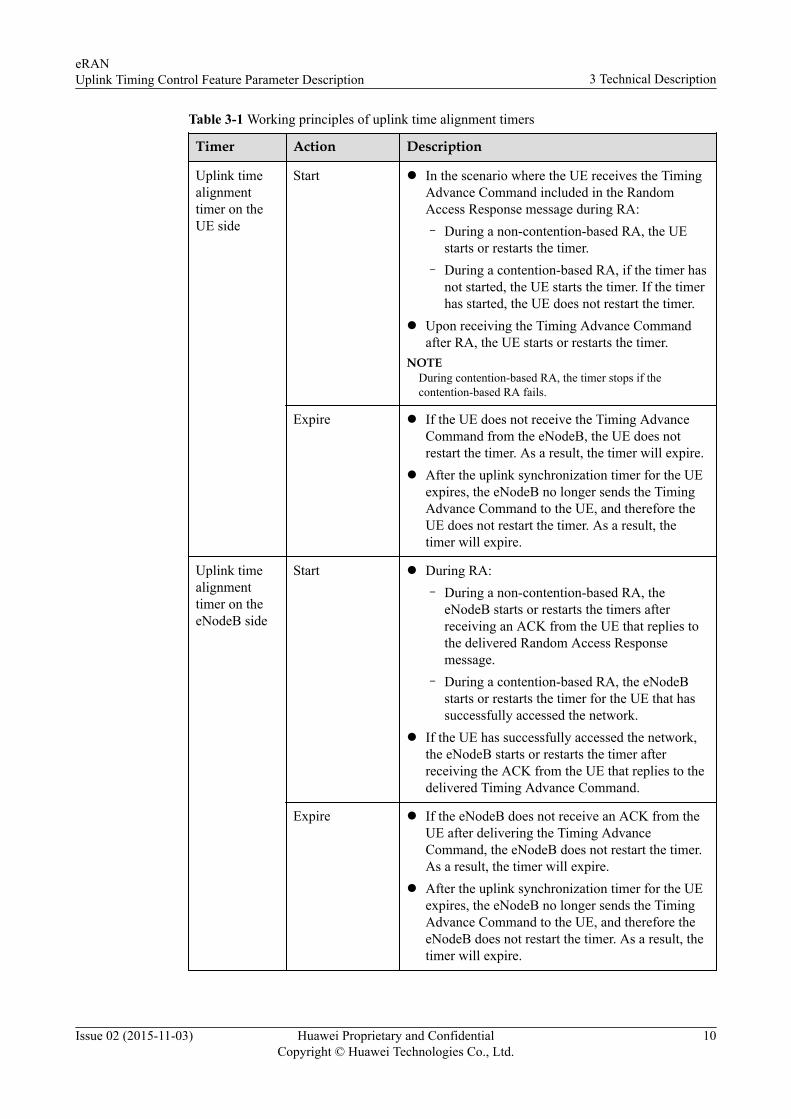
Table 3-1 Working principles of uplink time alignment timers
Timer Action Description
Uplink timealignmenttimer on theUE side
Start l In the scenario where the UE receives the TimingAdvance Command included in the RandomAccess Response message during RA:– During a non-contention-based RA, the UE
starts or restarts the timer.– During a contention-based RA, if the timer has
not started, the UE starts the timer. If the timerhas started, the UE does not restart the timer.
l Upon receiving the Timing Advance Commandafter RA, the UE starts or restarts the timer.
NOTEDuring contention-based RA, the timer stops if thecontention-based RA fails.
Expire l If the UE does not receive the Timing AdvanceCommand from the eNodeB, the UE does notrestart the timer. As a result, the timer will expire.
l After the uplink synchronization timer for the UEexpires, the eNodeB no longer sends the TimingAdvance Command to the UE, and therefore theUE does not restart the timer. As a result, thetimer will expire.
Uplink timealignmenttimer on theeNodeB side
Start l During RA:– During a non-contention-based RA, the
eNodeB starts or restarts the timers afterreceiving an ACK from the UE that replies tothe delivered Random Access Responsemessage.
– During a contention-based RA, the eNodeBstarts or restarts the timer for the UE that hassuccessfully accessed the network.
l If the UE has successfully accessed the network,the eNodeB starts or restarts the timer afterreceiving the ACK from the UE that replies to thedelivered Timing Advance Command.
Expire l If the eNodeB does not receive an ACK from theUE after delivering the Timing AdvanceCommand, the eNodeB does not restart the timer.As a result, the timer will expire.
l After the uplink synchronization timer for the UEexpires, the eNodeB no longer sends the TimingAdvance Command to the UE, and therefore theeNodeB does not restart the timer. As a result, thetimer will expire.
eRANUplink Timing Control Feature Parameter Description 3 Technical Description
Issue 02 (2015-11-03) Huawei Proprietary and ConfidentialCopyright © Huawei Technologies Co., Ltd.
10

Both the uplink time alignment timer on the UE side and that on the eNodeB side can berestarted during the running process to prolong the duration of uplink synchronization. Uponreceiving the Timing Advance Command from the eNodeB, the UE restarts its uplink timealignment timer and sends an ACK to the eNodeB. Upon receiving the ACK, the eNodeBrestarts its uplink time alignment timer, as shown in Figure 3-4.
Figure 3-4 Time to restart the uplink time alignment timers
Timer SettingsThe uplink time alignment timer on the UE side and the timer on the eNodeB side arecontrolled separately. The TimeAlignmentTimer.TimeAlignmentTimer parameter specifiesthe uplink time alignment timer length on the eNodeB side. After setting the timer value, thevalue is sent to the UE through air interface signaling.
l If the eNodeB adopts the periodic policy, it is recommended that theTimeAlignmentTimer.TimeAlignmentTimer parameter be set to SF1920(1920subframes). When the TimeAlignmentTimer.TimeAlignmentTimer parameter is set toa smaller value, the eNodeB sends the Timing Advance Command to the UE at a higherfrequency, more radio resources are consumed, and higher mobility speed can besupported. If the TimeAlignmentTimer.TimeAlignmentTimer parameter is set to alarger value, the opposite effect is generated.
l If the eNodeB adopts the periodic evaluation and event-triggering policy, it isrecommended that the TimeAlignmentTimer.TimeAlignmentTimer parameter be set toSF10240(10240 subframes). In heavy traffic scenarios where theTimeAlignmentTimer.TimingResOptSwitch parameter is set to ON(On), you areadvised to set the TimeAlignmentTimer.TimeAlignmentTimer parameter toINFINITY(Infinity). A smaller value of theTimeAlignmentTimer.TimeAlignmentTimer parameter (for example, less thanSF5120(5120 subframes)) leads to a higher probability of UEs in the discontinuousreception (DRX) state entering the out-of-synchronization state.
NOTE
For details about the relationship between the TimeAlignmentTimer.TimeAlignmentTimerparameter value and the DRX state, see DRX and Signaling Control Feature ParameterDescription.
eRANUplink Timing Control Feature Parameter Description 3 Technical Description
Issue 02 (2015-11-03) Huawei Proprietary and ConfidentialCopyright © Huawei Technologies Co., Ltd.
11

3.3.2 Uplink Synchronization Timer
Timer Working PrinciplesThe uplink synchronization timer controls whether the eNodeB continues to maintain uplinksynchronization between a UE and the eNodeB. The eNodeB maintains an uplinksynchronization timer for each UE.
Table 3-2 Working principles of the uplink synchronization timer
Action Description
Start The eNodeB starts or restarts the timer for a UE while sending data toor receiving data from the UE. Before the uplink synchronizationtimer for a UE expires, the eNodeB continuously sends the TimingAdvance Commands to the UE.
Expire After the uplink synchronization timer for a UE expires, the eNodeBno longer sends the Timing Advance Commands to the UE, anddetermines that the UE enters the out-of-synchronization state after theuplink time alignment timer on the eNodeB side expires.
Timer SettingsThe RrcConnStateTimer.UlSynTimer parameter specifies the uplink synchronization timerlength.
l A smaller value for this parameter leads to a higher probability of the UE entering theout-of-synchronization state, a shorter time for the UE to occupy PUCCH and SRSresources, and a larger number of RA requests initiated by the UE.
l A larger value for this parameter leads to a lower probability of the UE entering the out-of-synchronization state, a longer time for the UE to occupy PUCCH and SRS resources,and a smaller number of RA requests initiated by the UE.
NOTE
The RrcConnStateTimer.UlSynTimer parameter can be set only on the eNodeB side.
If the RrcConnStateTimer.UlSynTimer parameter is set to 0, the uplink synchronization timerwill never expire.
3.3.3 UE Inactivity Timer
Timer Working PrinciplesThe eNodeB determines whether a UE is in RRC_CONNECTED mode based on the state ofthe UE inactivity timer. Table 3-3 describes the working principles of this timer.
eRANUplink Timing Control Feature Parameter Description 3 Technical Description
Issue 02 (2015-11-03) Huawei Proprietary and ConfidentialCopyright © Huawei Technologies Co., Ltd.
12

Table 3-3 Working principles of the UE inactivity timer
Action Description
Start The eNodeB starts or restarts the timer for a UE while sending data toor receiving data from the UE. Before the UE inactivity timer expires,the eNodeB determines that the UE is in RRC_CONNECTED mode.
Expire After the UE inactivity timer expires, the eNodeB sends an RRCConnection Release message to the UE; the UE is then released andenters RRC_IDLE mode. This prevents an inactive UE fromoccupying radio resources when it is unnecessary.
NOTE
If the UE inactivity timer for an out-of-synchronized UE expires, the UE enters the synchronization statefirst. Then, the eNodeB sends an RRC Connection Release message to the UE, and the UE enters theidle mode.
Timer SettingsThe RrcConnStateTimer.UeInactiveTimer parameter specifies the length of the UEinactivity timer. In the scenario where a UE does not send data to or receive data from theeNodeB:
l If this parameter is set to a smaller value, the UE will be released earlier, and the UEsends the RRC connection setup requests to the eNodeB at a higher frequency. Becausethe number of UEs released normally increases, the service drop rate decreases.
l If this parameter is set to a larger value, the time required to release the UE will belonger, the RRC connection between the UE and the eNodeB maintains for a longertime, and the UE occupies radio resources for a longer time as well. Because the numberof UEs being released normally decreases, the service drop rate increases.
l If the value of RrcConnStateTimer.UlSynTimer is greater than the value ofRrcConnStateTimer.UeInactiveTimer, the UE enters the idle mode directly.
NOTE
The RrcConnStateTimer.UeInactiveTimer parameter can be set only on the eNodeB side. If theparameter setting is changed, the change applies to UEs that newly access the network.
If the RrcConnStateTimer.UeInactiveTimer parameter is set to 0, the timer does not take effect,which means the UEs are always in connected mode.
eRANUplink Timing Control Feature Parameter Description 3 Technical Description
Issue 02 (2015-11-03) Huawei Proprietary and ConfidentialCopyright © Huawei Technologies Co., Ltd.
13

4 Related Features
4.1 LBFD-070101 Uplink Timing Based on PUCCH
Prerequisite FeaturesNone
Mutually Exclusive FeaturesNone
Impacted Featuresl LOFD-001008 Ultra High Speed Mobility
LOFD-001008 Ultra High Speed Mobility takes priority over LBFD-070101 UplinkTiming Based on PUCCH. If the Cell.HighSpeedFlag parameter is set toULTRA_HIGH_SPEED(Ultra high speed cell flag) orEXTRA_HIGH_SPEED(Extra high speed cell flag), LBFD-070101 Uplink TimingBased on PUCCH does not take effect.
l LOFD-001031 Extended CPLOFD-001031 Extended CP takes priority over LBFD-070101 Uplink Timing Based onPUCCH. If the Cell.UlCyclicPrefix parameter is set to EXTENDED_CP(Extended),LBFD-070101 Uplink Timing Based on PUCCH does not take effect.
l LBFD-002017 DRX– When LBFD-002017 DRX is enabled, parameters related to DRX are restrained by
uplink timing. For details, see DRX and Signaling Control Feature ParameterDescription. When both LBFD-002017 DRX and LBFD-070101 Uplink TimingBased on PUCCH are enabled, parameters related to DRX are no longer restrainedby uplink timing, and therefore the power consumption of UEs in the DRX state canbe further reduced.
– If DRX is enabled, the eNodeB receives CQIs in PUCCH from UEs only when theUEs are in the DRX active time. The timing offset measurement accuracy dependson the number of CQIs in PUCCH received by the eNodeB. In scenarios where thelong DRX cycle duration is greater than or equal to 160 ms, to ensure that theeNodeB can measure accurate timing offset before delivering the Timing Advance
eRANUplink Timing Control Feature Parameter Description 4 Related Features
Issue 02 (2015-11-03) Huawei Proprietary and ConfidentialCopyright © Huawei Technologies Co., Ltd.
14
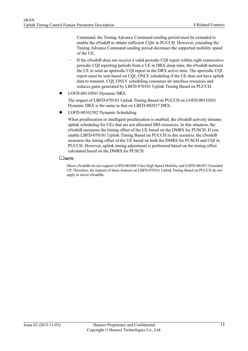
Command, the Timing Advance Command sending period must be extended toenable the eNodeB to obtain sufficient CQIs in PUCCH. However, extending theTiming Advance Command sending period decreases the supported mobility speedof the UE.
– If the eNodeB does not receive a valid periodic CQI report within eight consecutiveperiodic CQI reporting periods from a UE in DRX sleep time, the eNodeB instructsthe UE to send an aperiodic CQI report in the DRX active time. The aperiodic CQIreport must be sent based on CQI_ONLY scheduling if the UE does not have uplinkdata to transmit. CQI_ONLY scheduling consumes air interface resources andreduces gains generated by LBFD-070101 Uplink Timing Based on PUCCH.
l LOFD-00110501 Dynamic DRXThe impact of LBFD-070101 Uplink Timing Based on PUCCH on LOFD-00110501Dynamic DRX is the same as that on LBFD-002017 DRX.
l LOFD-00101502 Dynamic SchedulingWhen preallocation or intelligent preallocation is enabled, the eNodeB actively initiatesuplink scheduling for UEs that are not allocated SRS resources. In this situation, theeNodeB measures the timing offset of the UE based on the DMRS for PUSCH. If youenable LBFD-070101 Uplink Timing Based on PUCCH in this scenario, the eNodeBmeasures the timing offset of the UE based on both the DMRS for PUSCH and CQI inPUCCH. However, uplink timing adjustment is performed based on the timing offsetcalculated based on the DMRS for PUSCH.
NOTE
Micro eNodeBs do not support LOFD-001008 Ultra High Speed Mobility and LOFD-001031 ExtendedCP. Therefore, the impacts of these features on LBFD-070101 Uplink Timing Based on PUCCH do notapply to micro eNodeBs.
eRANUplink Timing Control Feature Parameter Description 4 Related Features
Issue 02 (2015-11-03) Huawei Proprietary and ConfidentialCopyright © Huawei Technologies Co., Ltd.
15

5 Network Impact
5.1 LBFD-070101 Uplink Timing Based on PUCCH
System CapacityIn LBFD-070101 Uplink Timing Based on PUCCH, when the eNodeB adopts the periodicevaluation and event-triggering policy, fewer control channel elements (CCEs) in the PDCCHare consumed for measuring uplink timing offset based on DMRS for PUSCH, and thereforethe PDCCH can support more UEs. The number of reduced CCEs varies according to siterequirements and cannot be quantified. This is because the number depends on the number ofusers in a network, user distribution, and service type.
Network PerformanceIn LBFD-070101 Uplink Timing Based on PUCCH, when the eNodeB adopts the periodicevaluation and event-triggering policy, fewer physical resource blocks (PRBs) in the PUSCHare consumed for measuring uplink timing offset based on DMRS for PUSCH, and the usageof PRB in the PUSCH decreases. If there is a large number of UEs in the cell, both thenumber of service drops and the number of E-RAB setup failures may slightly increase. Thechange varies according to site requirements and cannot be quantified. This is because suchKPIs depend on the number of users in a network, user distribution, and service type.
eRANUplink Timing Control Feature Parameter Description 5 Network Impact
Issue 02 (2015-11-03) Huawei Proprietary and ConfidentialCopyright © Huawei Technologies Co., Ltd.
16

6 Engineering Guidelines
6.1 When to Use LAOFD-001001 and LAOFD-001002It is recommended that LBFD-070101 Uplink Timing Based on PUCCH be enabled whenboth the following conditions are met:
l The SRS resources cannot support uplink timing required by all the UEs in a cell. Thatis, the average number of uplink synchronized UEs is greater than the average number ofUEs allocated with SRS resources (the value of the L.Traffic.User.Ulsync.Avg counterspecified by the counter ID 1526728481 is greater than the value of theL.Traffic.User.SRS.Avg counter specified by the counter ID 1526728481) or no SRSresources are available in the cell (the SRSCFG.SrsCfgInd parameter is set toBOOLEAN_FALSE(False)).
l Preallocation does not take effect, for example, when DRX is enabled.
6.2 Required InformationN/A
6.3 PlanningN/A
6.4 Deployment
6.4.1 Requirements
Operating Environment
LBFD-070101 Uplink Timing Based on PUCCH must work with the LBBPd or UBBPd.
eRANUplink Timing Control Feature Parameter Description 6 Engineering Guidelines
Issue 02 (2015-11-03) Huawei Proprietary and ConfidentialCopyright © Huawei Technologies Co., Ltd.
17

Transmission NetworkingNone
LicenseNone
6.4.2 Data PreparationThis section describes the data that you need to collect for setting parameters. Required data isdata that you must collect for all scenarios. Collect scenario-specific data when necessary fora specific feature deployment scenario.
There are three types of data sources: data sources:
l Network plan (negotiation required): parameter values planned by the operator andnegotiated with the evolved packet core (EPC) or peer transmission equipment
l Network plan (negotiation not required): parameter values planned and set by theoperator
l User-defined: parameter values set by users.
Required DataThe following table describes the parameters that must be set in the TimeAlignmentTimerMO to configure uplink timing measurement mode, the switch used to optimize the uplinktiming command, and the uplink time alignment timer length.
eRANUplink Timing Control Feature Parameter Description 6 Engineering Guidelines
Issue 02 (2015-11-03) Huawei Proprietary and ConfidentialCopyright © Huawei Technologies Co., Ltd.
18
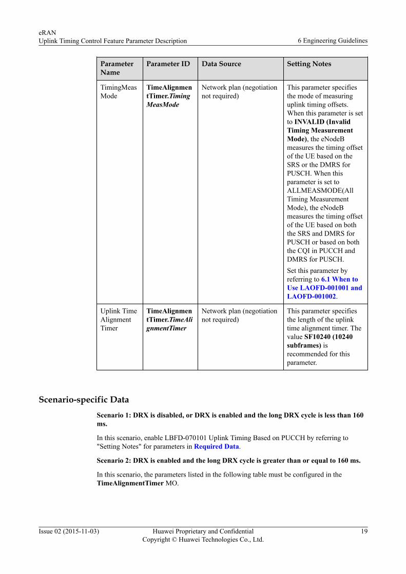
ParameterName
Parameter ID Data Source Setting Notes
TimingMeasMode
TimeAlignmentTimer.TimingMeasMode
Network plan (negotiationnot required)
This parameter specifiesthe mode of measuringuplink timing offsets.When this parameter is setto INVALID (InvalidTiming MeasurementMode), the eNodeBmeasures the timing offsetof the UE based on theSRS or the DMRS forPUSCH. When thisparameter is set toALLMEASMODE(AllTiming MeasurementMode), the eNodeBmeasures the timing offsetof the UE based on boththe SRS and DMRS forPUSCH or based on boththe CQI in PUCCH andDMRS for PUSCH.Set this parameter byreferring to 6.1 When toUse LAOFD-001001 andLAOFD-001002.
Uplink TimeAlignmentTimer
TimeAlignmentTimer.TimeAlignmentTimer
Network plan (negotiationnot required)
This parameter specifiesthe length of the uplinktime alignment timer. Thevalue SF10240 (10240subframes) isrecommended for thisparameter.
Scenario-specific DataScenario 1: DRX is disabled, or DRX is enabled and the long DRX cycle is less than 160ms.
In this scenario, enable LBFD-070101 Uplink Timing Based on PUCCH by referring to"Setting Notes" for parameters in Required Data.
Scenario 2: DRX is enabled and the long DRX cycle is greater than or equal to 160 ms.
In this scenario, the parameters listed in the following table must be configured in theTimeAlignmentTimer MO.
eRANUplink Timing Control Feature Parameter Description 6 Engineering Guidelines
Issue 02 (2015-11-03) Huawei Proprietary and ConfidentialCopyright © Huawei Technologies Co., Ltd.
19
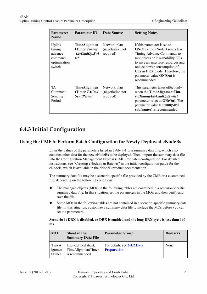
ParameterName
Parameter ID Data Source Setting Notes
Uplinktimingadvancecommandoptimizationswitch
TimeAlignmentTimer.TimingAdvCmdOptSwitch
Network plan(negotiation notrequired)
If this parameter is set toON(On), the eNodeB sends lessTiming Advance Commands tomotionless or low-mobility UEsto save air interface resources andreduce power consumption ofUEs in DRX mode. Therefore, theparameter value ON(On) isrecommended.
TACommandSendingPeriod
TimeAlignmentTimer.TACmdSendPeriod
Network plan(negotiation notrequired)
This parameter takes effect onlywhen the TimeAlignmentTim-er.TimingAdvCmdOptSwitchparameter is set to ON(On). Theparameter value SF5088(5088subframes) is recommended.
6.4.3 Initial Configuration
Using the CME to Perform Batch Configuration for Newly Deployed eNodeBs
Enter the values of the parameters listed in Table 7-1 in a summary data file, which alsocontains other data for the new eNodeBs to be deployed. Then, import the summary data fileinto the Configuration Management Express (CME) for batch configuration. For detailedinstructions, see "Creating eNodeBs in Batches" in the initial configuration guide for theeNodeB, which is available in the eNodeB product documentation.
The summary data file may be a scenario-specific file provided by the CME or a customizedfile, depending on the following conditions:
l The managed objects (MOs) in the following tables are contained in a scenario-specificsummary data file. In this situation, set the parameters in the MOs, and then verify andsave the file.
l Some MOs in the following tables are not contained in a scenario-specific summary datafile. In this situation, customize a summary data file to include the MOs before you canset the parameters.
Scenario 1: DRX is disabled, or DRX is enabled and the long DRX cycle is less than 160ms.
MO Sheet in theSummary Data File
Parameter Group Remarks
TimeAlignmentTimer
User-defined sheet,TimeAlignmentTimeris recommended.
For details, see 6.4.2 DataPreparation.
None
eRANUplink Timing Control Feature Parameter Description 6 Engineering Guidelines
Issue 02 (2015-11-03) Huawei Proprietary and ConfidentialCopyright © Huawei Technologies Co., Ltd.
20

Scenario 2: DRX is enabled and the long DRX cycle is greater than or equal to 160 ms.
MO Sheet in theSummary Data File
Parameter Group Remarks
TimeAlignmentTimer
User-defined sheet,TimeAlignmentTimeris recommended.
For details, see 6.4.2 DataPreparation.
None
Using the CME to Perform Batch Configuration for Existing eNodeBsBatch reconfiguration using the CME is the recommended method to activate a feature onexisting eNodeBs. This method reconfigures all data, except neighbor relationships, formultiple eNodeBs in a single procedure.
Step 1 Choose CME > Advanced > Customize Summary Data File (U2000 client mode), orchoose Advanced > Customize Summary Data File (CME client mode), to customize asummary data file for batch reconfiguration.
NOTE
For context-sensitive help on a current task in the client, press F1.
Step 2 Choose CME > LTE Application > Export Data > Export Base Station BulkConfiguration Data (U2000 client mode), or choose Advanced > Base Station BulkConfiguration > Export Data (CME client mode), to export the eNodeB data stored on theCME into the customized summary data file.
Step 3 In the summary data file, set the parameters in the MOs and close the file.
Step 4 Choose CME > LTE Application > Import Data > Import Base Station BulkConfiguration Data (U2000 client mode), or choose LTE Application > Import Data >Import Base Station Bulk Configuration Data (CME client mode), to import the summarydata file into the CME.
Step 5 Choose CME > Planned Area > Export Incremental Scripts (U2000 client mode), orchoose Area Management > Planned Area > Export Incremental Scripts (CME clientmode), to export and activate the incremental scripts.
----End
Using the CME to Perform Single ConfigurationOn the CME, set the parameters listed in the "Data Preparation" section for a single eNodeB.The procedure is as follows:
Step 1 In the planned data area, click Base Station in the upper left corner of the configurationwindow.
Step 2 In area 1 shown in Figure 6-1, select the eNodeB to which the MOs belong.
eRANUplink Timing Control Feature Parameter Description 6 Engineering Guidelines
Issue 02 (2015-11-03) Huawei Proprietary and ConfidentialCopyright © Huawei Technologies Co., Ltd.
21

Figure 6-1 MO search and configuration window
Step 3 On the Search tab page in area 2, enter an MO name, for example, CELL.
Step 4 In area 3, double-click the MO in the Object Name column. All parameters in this MO aredisplayed in area 4.
Step 5 Set the parameters in area 4 or 5.
Step 6 Choose CME > Planned Area > Export Incremental Scripts (U2000 client mode), orchoose Area Management > Planned Area > Export Incremental Scripts (CME clientmode) in the main menu of the planned area, to export and activate the incremental scripts.
----End
Using MML Commands
Scenario 1: DRX is disabled, or DRX is enabled and the long DRX cycle is less than 160ms.
Step 1 Run the MOD TATIMER command to set parameters TimingMeasMode andTimeAlignmentTimer.
----End
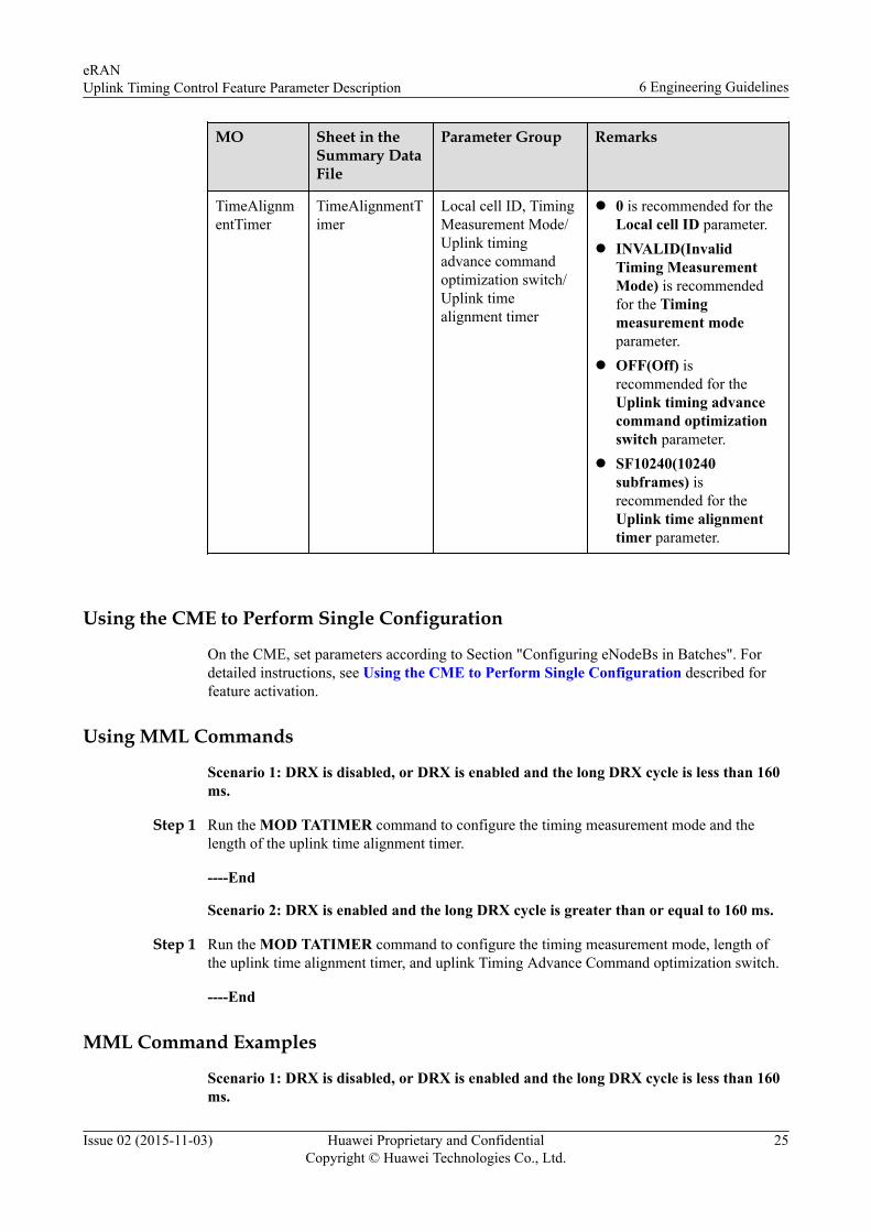
Scenario 2: DRX is enabled and the long DRX cycle is greater than or equal to 160 ms.
Step 1 Run the MOD TATIMER command to configure the timing measurement mode, length ofthe uplink time alignment timer, uplink Timing Advance Command optimization switch, andTiming Advance Command sending period.
----End
eRANUplink Timing Control Feature Parameter Description 6 Engineering Guidelines
Issue 02 (2015-11-03) Huawei Proprietary and ConfidentialCopyright © Huawei Technologies Co., Ltd.
22

MML Command Examples
Scenario 1: DRX is disabled, or DRX is enabled and the long DRX cycle is less than 160ms.
MOD TATIMER: LocalCellId=0, TimingMeasMode=ALLMEASMODE, TimeAlignmentTimer=SF10240;
Scenario 2: DRX is enabled and the long DRX cycle is greater than or equal to 160 ms.
MOD TATIMER: LocalCellId=0, TimingMeasMode=ALLMEASMODE, TimeAlignmentTimer=SF10240, TimingAdvCmdOptSwitch=ON, TACmdSendPeriod=SF5088;
6.4.4 Activation Observation
Using MML Commands
Run the LST TATIMER command on the eNodeB to verify that the TimingMeasModeparameter value is ALLMEASMODE. If yes, LBFD-070101 Uplink Timing based onPUCCH has been activated by performing the following operation:
Using Performance Counters
If the values of both counters listed in Table 6-1 are not zero, LBFD-070101 Uplink Timingbased on PUCCH takes effects.
Table 6-1 Counters related to uplink timing control
Counter ID Counter Name Description
1526730143 L.Traffic.User.TAMeas.PUCCH.Avg
This counter specifies the averagenumber of users whose uplink timingoffsets are measured based on thePUCCH.
1526730144 L.Traffic.User.TAMeas.PUCCH.Max
This counter specifies the maximumnumber of users whose uplink timingoffsets are measured based on thePUCCH.
6.4.5 Deactivation
Using the CME to Perform Batch Configuration
Batch reconfiguration using the CME is the recommended method to deactivate a feature oneNodeBs. This method reconfigures all data, except neighbor relationships, for multipleeNodeBs in a single procedure. The procedure for feature deactivation is similar to that forfeature activation described in "Using the CME to Perform Batch Configuration for ExistingeNodeBs". In the procedure, modify parameters according to Using the CME to PerformBatch Configuration for Existing eNodeBs.
Scenario 1: DRX is disabled, or DRX is enabled and the long DRX cycle is less than 160ms.
eRANUplink Timing Control Feature Parameter Description 6 Engineering Guidelines
Issue 02 (2015-11-03) Huawei Proprietary and ConfidentialCopyright © Huawei Technologies Co., Ltd.
23
MO Sheet in theSummary Data File
ParameterGroup
Remarks
TimeAlignmentTimer
TimeAlignmentTimer Local cell ID,TimingMeasurementMode, Uplinktime alignmenttimer
l 0 is recommended forthe Local cell IDparameter.
l INVALID(InvalidTiming MeasurementMode) is recommendedfor the Timingmeasurement modeparameter.
l SF1920(1920subframes) isrecommended for theUplink time alignmenttimer parameter if theTimeAlignmentTim-er.TimingAdvCmdOptS-witch parameter is set toOFF(Off).
l SF10240(10240subframes) isrecommended for theUplink time alignmenttimer parameter if theTimeAlignmentTim-er.TimingAdvCmdOptS-witch parameter is set toON(On).
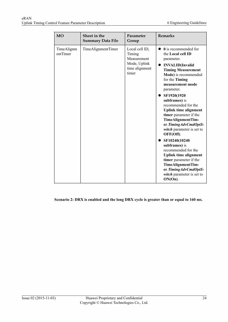
Scenario 2: DRX is enabled and the long DRX cycle is greater than or equal to 160 ms.
eRANUplink Timing Control Feature Parameter Description 6 Engineering Guidelines
Issue 02 (2015-11-03) Huawei Proprietary and ConfidentialCopyright © Huawei Technologies Co., Ltd.
24
MO Sheet in theSummary DataFile
Parameter Group Remarks
TimeAlignmentTimer
TimeAlignmentTimer
Local cell ID, TimingMeasurement Mode/Uplink timingadvance commandoptimization switch/Uplink timealignment timer
l 0 is recommended for theLocal cell ID parameter.
l INVALID(InvalidTiming MeasurementMode) is recommendedfor the Timingmeasurement modeparameter.
l OFF(Off) isrecommended for theUplink timing advancecommand optimizationswitch parameter.
l SF10240(10240subframes) isrecommended for theUplink time alignmenttimer parameter.
Using the CME to Perform Single Configuration
On the CME, set parameters according to Section "Configuring eNodeBs in Batches". Fordetailed instructions, see Using the CME to Perform Single Configuration described forfeature activation.
Using MML Commands
Scenario 1: DRX is disabled, or DRX is enabled and the long DRX cycle is less than 160ms.
Step 1 Run the MOD TATIMER command to configure the timing measurement mode and thelength of the uplink time alignment timer.
----End
Scenario 2: DRX is enabled and the long DRX cycle is greater than or equal to 160 ms.
Step 1 Run the MOD TATIMER command to configure the timing measurement mode, length ofthe uplink time alignment timer, and uplink Timing Advance Command optimization switch.
----End
MML Command Examples
Scenario 1: DRX is disabled, or DRX is enabled and the long DRX cycle is less than 160ms.
eRANUplink Timing Control Feature Parameter Description 6 Engineering Guidelines
Issue 02 (2015-11-03) Huawei Proprietary and ConfidentialCopyright © Huawei Technologies Co., Ltd.
25

If the TimeAlignmentTimer.TimingAdvCmdOptSwitch parameter is set to OFF(Off),SF1920(1920 subframes) is recommended for the Uplink time alignment timer parameter.
MOD TATIMER: LocalCellId=0, TimingMeasMode=INVALID, TimeAlignmentTimer=SF1920;
If the TimeAlignmentTimer.TimingAdvCmdOptSwitch parameter is set to ON(On),SF10240(10240 subframes) is recommended for the Uplink time alignment timerparameter.
MOD TATIMER: LocalCellId=0, TimingMeasMode=INVALID, TimeAlignmentTimer=SF10240;
Scenario 2: DRX is enabled and the long DRX cycle is greater than or equal to 160 ms.
MOD TATIMER: LocalCellId=0, TimingMeasMode=INVALID, TimeAlignmentTimer=SF10240, TimingAdvCmdOptSwitch=OFF;
6.4.6 ReconfigurationThe following table describes the parameters that must be set in the RrcConnStateTimerMO to configure the uplink synchronization timer length and the length of the UE inactivitytimer.
ParameterName
Parameter ID Source Setting Notes
Uplink SyncTimer
RrcConnStateTimer.UlSynTimer
Network plan(negotiation notrequired)
This parameter indicates the timerused to govern the period inwhich the eNodeB maintainsuplink synchronization for a UE.After this timer expires, theeNodeB does not send TimingAdvance Command to the UE.The default value for thisparameter is 180.
Ue inactivetimer
RrcConnStateTimer.UeInactiveTimer
Network plan(negotiation notrequired)
This parameter indicates theduration within which theeNodeB receives or sends data tothe UE. The default value for thisparameter is 20.
MML Command ExamplesMOD RRCCONNSTATETIMER: UlSynTimer=180, UeInactiveTimer=20;
6.5 Performance MonitoringThe operation of LBFD-070101 Uplink Timing Based on PUCCH can be monitored based onthe counters in Table 6-2.
eRANUplink Timing Control Feature Parameter Description 6 Engineering Guidelines
Issue 02 (2015-11-03) Huawei Proprietary and ConfidentialCopyright © Huawei Technologies Co., Ltd.
26

Table 6-2 Counters related to uplink timing control
Counter ID Counter Name Description
1526730143 L.Traffic.User.TAMeas.PUCCH.Avg
This counter specifies the averagenumber of users whose uplinktiming offsets are measured basedon the PUCCH.
1526730144 L.Traffic.User.TAMeas.PUCCH.Max
This counter specifies themaximum number of users whoseuplink timing offsets are measuredbased on the PUCCH.
1526728764 L.ChMeas.PRB.PUSCH.Avg This counter specifies the numberof used PRBs in the PUSCH.
1526728304 L.ChMeas.CCE.ULUsed This counter specifies the numberof CCEs in the PDCCH used tocarry DCIs for uplink transmission.
1526728566 to1526728597
L.ChMeas.PUSCH.MCS.0~L.ChMeas.PUSCH.MCS.31
These counters specify the numberof times that MCS index 0 to 31 isscheduled on the PUSCH
After LBFD-070101 Uplink Timing Based on PUCCH is enabled, the uplink timing offsets ofsome UEs in a cell are measured based on the CQI in PUCCH, which reduces radio resourcesconsumed by uplink timing offset measurement based on the DMRS for PUSCH. Therefore,the actual number of CCCH blocks for paging can be calculated as follows:
l Observe the L.Traffic.User.TAMeas.PUCCH.Avg counter to obtain the average numberof users whose uplink timing offsets are measured based on the PUCCH.
l Observe the L.Traffic.User.TAMeas.PUCCH.Max counter to obtain the maximumnumber of users whose uplink timing offsets are measured based on the PUCCH.
l Observe the L.ChMeas.PRB.PUSCH.Avg counter to verify that the number of usedPRBs in the PUSCH decreases.
l Observe the L.ChMeas.CCE.ULUsed counter to verify that the number of CCEs in thePDCCH used to carry DCIs for uplink transmission decreases.
l Observe counters from L.ChMeas.PUSCH.MCS.0 to L.ChMeas.PUSCH.MCS.31 toverify that the number of scheduling times in the PUSCH decreases. The number ofscheduling times in the PUSCH is the value of the sum of counters fromL.ChMeas.PUSCH.MCS.0 to L.ChMeas.PUSCH.MCS.31.
6.6 Parameter OptimizationWhen DRX is enabled, scheduling request (SR) false detections cause unnecessary uplinkscheduling, which consumes air interface resources and reduces gains generated byLBFD-070101 Uplink Timing Based on PUCCH.
PUSCH discontinuous transmission (DTX) detections help avoid unnecessary uplinkscheduling caused by SR false detections. Therefore, if both DRX and LBFD-070101 UplinkTiming Based on PUCCH are enabled, you are advised to enable PUSCH DTX detection.
eRANUplink Timing Control Feature Parameter Description 6 Engineering Guidelines
Issue 02 (2015-11-03) Huawei Proprietary and ConfidentialCopyright © Huawei Technologies Co., Ltd.
27

6.7 TroubleshootingNone
eRANUplink Timing Control Feature Parameter Description 6 Engineering Guidelines
Issue 02 (2015-11-03) Huawei Proprietary and ConfidentialCopyright © Huawei Technologies Co., Ltd.
28

7 Parameters
Table 7-1 Parameters
MO Parameter ID
MMLCommand
FeatureID
FeatureName
Description
TimeAlignmentTimer
TACmdSendPeriod
MODTATIMERLSTTATIMER
None None Meaning: Indicates the interval for sending the TimingAdvance Command to UEs. This parameter needs tobe set only when the TimingAdvCmdOptSwitchparameter is set to ON. If this parameter is set toInvalid, none of parameter settings in the MMLCommand window takes effect.GUI Value Range: INVALID(NULL), SF218(218subframes), SF343(343 subframes), SF608(608subframes), SF928(928 subframes), SF1248(1248subframes), SF2528(2528 subframes), SF5088(5088subframes)Unit: NoneActual Value Range: INVALID, SF218, SF343,SF608, SF928, SF1248, SF2528, SF5088Default Value: SF928(928 subframes)
eRANUplink Timing Control Feature Parameter Description 7 Parameters
Issue 02 (2015-11-03) Huawei Proprietary and ConfidentialCopyright © Huawei Technologies Co., Ltd.
29

MO Parameter ID
MMLCommand
FeatureID
FeatureName
Description
TimeAlignmentTimer
TimingMeasMode
MODTATIMERLSTTATIMER
LBFD-070101
UplinkTimingBasedonPUCCH
Meaning: Indicates the method of measuring uplinktiming offsets. If this parameter is set to INVALID,uplink timing offsets are measured based on thedemodulation reference signal (DMRS) for PUSCH orsounding reference signal (SRS). If this parameter isset to ALLMEASMODE, uplink timing offsets aremeasured based on the DMRS for PUSCH and SRS orbased on the DMRS for PUSCH and channel qualityindicator (CQI) in PUCCH. In addition, the value ONof the TimingAdvCmdOptSwitch parameter takeseffect regardless of the actual parameter setting. Thatis, the eNodeB always sends the Timing AdvanceCommand to UEs. In this case, it is recommended thatthe TimeAlignmentTimer parameter be set toSF10240. The value ALLMEASMODE applies onlyto LTE FDD cells. The parameter value INVALIDtakes effect in a cell regardless of the actual parametersetting in any of the following scenarios: (1) The cellis established on an LBBPc. (2) The UlCyclicPrefixparameter is set to EXTENDED_CP. (3) TheHighSpeedFlag parameter is set to HIGH_SPEED,ULTRA_HIGH_SPEED, or EXTRA_HIGH_SPEED.(4) The TX/RX mode of the cell is 2T8R.GUI Value Range: INVALID(Invalid TimingMeasurement Mode), ALLMEASMODE(All TimingMeasurement Mode)Unit: NoneActual Value Range: INVALID, ALLMEASMODEDefault Value: INVALID(Invalid TimingMeasurement Mode)
eRANUplink Timing Control Feature Parameter Description 7 Parameters
Issue 02 (2015-11-03) Huawei Proprietary and ConfidentialCopyright © Huawei Technologies Co., Ltd.
30

MO Parameter ID
MMLCommand
FeatureID
FeatureName
Description
TimeAlignmentTimer
TimingResOptSwitch
MODTATIMERLSTTATIMER
None None Meaning: Indicates whether to enable the mechanismof optimized resource scheduling for uplink timing.Ifthis parameter is set to OFF, the eNodeB adopts theexisting resource scheduling policy for uplink timing,which consumes a large amount of resources used fordelivering Timing Advance Commands in large trafficscenarios.If this parameter is set to ON, the eNodeBadopts the mechanism of optimized resourcescheduling for uplink timing, which reduces thenumber of unnecessary Timing Advance Commandsto be delivered and reduces resources allocated foruplink timing in large traffic scenarios.This parameterapplies only to LTE FDD cells. The parameter valueON is recommended in heavily loaded cells wherethere is a large number of UEs.GUI Value Range: OFF(Off), ON(On)Unit: NoneActual Value Range: OFF, ONDefault Value: ON(On)
TimeAlignmentTimer
TimingAdvCmdOptSwitch
MODTATIMERLSTTATIMER
None None Meaning:Indicates whether optimization of the mechanism fordelivering the uplink time alignment command takeseffect. If the optimization takes effect, the number ofunnecessary uplink time alignment commandsdelivered to motionless or low-mobility UEs can bereduced to save air interface resources and reducepower consumption of UEs in DRX mode. Thisensures the uplink time alignment performance if thelength of the uplink time alignment timer is set to alarge value.
If this parameter is set to ON, it is recommended thatthe TimeAlignmentTimer parameter be set toSF10240. A smaller value of the TimeAlignmentTim-er parameter, such as SF5120, leads to a higherprobability of becoming out-of-synchronization in theuplink for UEs in DRX mode.
If this parameter is set to ON, it is recommended thatthe LongDrxCycle parameter be smaller than or equalto SF320. Otherwise, the uplink time alignmentperformance of UEs in DRX mode is affected.GUI Value Range: OFF(Off), ON(On)Unit: NoneActual Value Range: OFF, ONDefault Value: ON(On)
eRANUplink Timing Control Feature Parameter Description 7 Parameters
Issue 02 (2015-11-03) Huawei Proprietary and ConfidentialCopyright © Huawei Technologies Co., Ltd.
31

MO Parameter ID
MMLCommand
FeatureID
FeatureName
Description
TimeAlignmentTimer
TimeAlignmentTimer
MODTATIMERLSTTATIMER
None None Meaning: Indicates the length of the uplink timealignment timer for UEs in the cell. A UE isconsidered not time-aligned in the uplink if the timerexpires.GUI Value Range: SF500(500 subframes), SF750(750subframes), SF1280(1280 subframes), SF1920(1920subframes), SF2560(2560 subframes), SF5120(5120subframes), SF10240(10240 subframes),INFINITY(Infinity)Unit: NoneActual Value Range: SF500, SF750, SF1280, SF1920,SF2560, SF5120, SF10240, INFINITYDefault Value: INFINITY(Infinity)
RrcConnStateTimer
UlSynTimer
MODRRCCONNSTATETIMERLSTRRCCONNSTATETIMER
LBFD-002007 /TDLBFD-002007
RRCConnectionManagement
Meaning: Indicates the timer used to govern theperiod in which the eNodeB maintains uplinksynchronization for a UE. After this timer expires, theeNodeB does not send Timing Advance Command tothe UE. This parameter does not take effect if it is setto 0. That is, the eNodeB will constantly send TimingAdvance Command to the UE to maintain uplinksynchronization for the UE.GUI Value Range: 0~3600Unit: sActual Value Range: 0~3600Default Value: 180
RrcConnStateTimer
UeInactiveTimer
MODRRCCONNSTATETIMERLSTRRCCONNSTATETIMER
LBFD-002007 /TDLBFD-002007
RRCConnectionManagement
Meaning: Indicates the length of the UE inactivitytimer for UEs that are running non-QCI1 services. Ifthe eNodeB detects that a UE has neither received norsent data for a duration exceeding the value of thisparameter, the eNodeB releases the RRC connectionfor the UE. If this parameter is set to 0, the UEinactivity timer is not used. If the parameter setting ischanged, the change applies to UEs that newly accessthe network.GUI Value Range: 0~3600Unit: sActual Value Range: 0~3600Default Value: 20
eRANUplink Timing Control Feature Parameter Description 7 Parameters
Issue 02 (2015-11-03) Huawei Proprietary and ConfidentialCopyright © Huawei Technologies Co., Ltd.
32

MO Parameter ID
MMLCommand
FeatureID
FeatureName
Description
Cell HighSpeedFlag
ADDCELLMODCELLLSTCELL
LOFD-001007 /TDLOFD-001007LOFD-001008
HighSpeedMobilityUltraHighSpeedMobility
Meaning: Indicates the speed flag of the cell. Set thisparameter to HIGH_SPEED if the cell is used toprovide coverage for an ultra-high-speed railway. Setthis parameter to LOW_SPEED in other scenarios.TDD cells with a bandwidth of 5 MHz or in 8T8Rmode can only be configured as low speed cells. TDDcells don't support ULTRA_HIGH_SPEED mode.GUI Value Range: LOW_SPEED(Low speed cellflag), HIGH_SPEED(High speed cell flag),ULTRA_HIGH_SPEED(Ultra high speed cell flag),EXTRA_HIGH_SPEED(Extra high speed cell flag)Unit: NoneActual Value Range: LOW_SPEED, HIGH_SPEED,ULTRA_HIGH_SPEED, EXTRA_HIGH_SPEEDDefault Value: LOW_SPEED(Low speed cell flag)
Cell UlCyclicPrefix
ADDCELLMODCELLLSTCELL
LBFD-00100401/TDLBFD-00100401LOFD-001031 /TDLOFD-001031LBFD-002009 /TDLBFD-002009
NormalCPExtended CPBroadcast ofsysteminformation
Meaning: Indicates the UL cyclic prefix length of acell. A cyclic prefix can be a common or extendedcyclic prefix. An extended cyclic prefix is generallyused in a complex environment with a strong multi-path effect and long delay. In a cell, the UL cyclicprefix length can be different from the DL one. Inaddition, the UL or DL cyclic prefix length of a cellmust be the same as that of the cell using the sameBBP. For details, see 3GPP TS 36.211.
GUI Value Range: NORMAL_CP(Normal),EXTENDED_CP(Extended)
Unit: None
Actual Value Range: NORMAL_CP,EXTENDED_CP
Default Value: NORMAL_CP(Normal)
eRANUplink Timing Control Feature Parameter Description 7 Parameters
Issue 02 (2015-11-03) Huawei Proprietary and ConfidentialCopyright © Huawei Technologies Co., Ltd.
33
MO Parameter ID
MMLCommand
FeatureID
FeatureName
Description
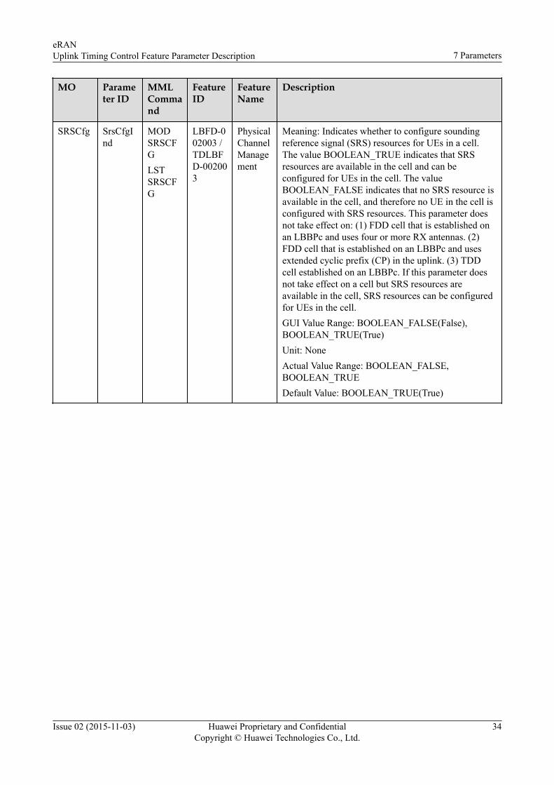
SRSCfg SrsCfgInd
MODSRSCFGLSTSRSCFG
LBFD-002003 /TDLBFD-002003
PhysicalChannelManagement
Meaning: Indicates whether to configure soundingreference signal (SRS) resources for UEs in a cell.The value BOOLEAN_TRUE indicates that SRSresources are available in the cell and can beconfigured for UEs in the cell. The valueBOOLEAN_FALSE indicates that no SRS resource isavailable in the cell, and therefore no UE in the cell isconfigured with SRS resources. This parameter doesnot take effect on: (1) FDD cell that is established onan LBBPc and uses four or more RX antennas. (2)FDD cell that is established on an LBBPc and usesextended cyclic prefix (CP) in the uplink. (3) TDDcell established on an LBBPc. If this parameter doesnot take effect on a cell but SRS resources areavailable in the cell, SRS resources can be configuredfor UEs in the cell.GUI Value Range: BOOLEAN_FALSE(False),BOOLEAN_TRUE(True)Unit: NoneActual Value Range: BOOLEAN_FALSE,BOOLEAN_TRUEDefault Value: BOOLEAN_TRUE(True)
eRANUplink Timing Control Feature Parameter Description 7 Parameters
Issue 02 (2015-11-03) Huawei Proprietary and ConfidentialCopyright © Huawei Technologies Co., Ltd.
34

8 Counters
Table 8-1 Counters
Counter ID Counter Name CounterDescription
Feature ID Feature Name
1526727412 L.ChMeas.PUSCH.MCS.0
Number of timesMCS index 0 isscheduled on thePUSCH
Multi-mode: NoneGSM: NoneUMTS: NoneLTE:LBFD-002025LBFD-001005TDLBFD-002025TDLBFD-001005
Basic SchedulingModulation: DL/ULQPSK, DL/UL16QAM, DL64QAMBasic SchedulingModulation: DL/ULQPSK, DL/UL16QAM, DL64QAM
1526727443 L.ChMeas.PUSCH.MCS.31
Number of timesMCS index 31 isscheduled on thePUSCH
Multi-mode: None
GSM: None
UMTS: None
LTE:LBFD-002025
TDLBFD-002025
LBFD-001005
TDLBFD-001005
LOFD-001006
TDLOFD-001006
Basic SchedulingBasic SchedulingModulation: DL/ULQPSK, DL/UL16QAM, DL64QAMModulation: DL/ULQPSK, DL/UL16QAM, DL64QAMUL 64QAMUL 64QAM
eRANUplink Timing Control Feature Parameter Description 8 Counters
Issue 02 (2015-11-03) Huawei Proprietary and ConfidentialCopyright © Huawei Technologies Co., Ltd.
35
Counter ID Counter Name CounterDescription
Feature ID Feature Name
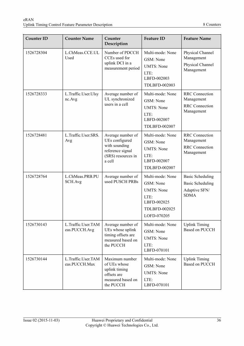
1526728304 L.ChMeas.CCE.ULUsed
Number of PDCCHCCEs used foruplink DCI in ameasurement period
Multi-mode: NoneGSM: NoneUMTS: NoneLTE:LBFD-002003TDLBFD-002003
Physical ChannelManagementPhysical ChannelManagement
1526728333 L.Traffic.User.Ulsync.Avg
Average number ofUL synchronizedusers in a cell
Multi-mode: NoneGSM: NoneUMTS: NoneLTE:LBFD-002007TDLBFD-002007
RRC ConnectionManagementRRC ConnectionManagement
1526728481 L.Traffic.User.SRS.Avg
Average number ofUEs configuredwith soundingreference signal(SRS) resources ina cell
Multi-mode: NoneGSM: NoneUMTS: NoneLTE:LBFD-002007TDLBFD-002007
RRC ConnectionManagementRRC ConnectionManagement
1526728764 L.ChMeas.PRB.PUSCH.Avg
Average number ofused PUSCH PRBs
Multi-mode: NoneGSM: NoneUMTS: NoneLTE:LBFD-002025TDLBFD-002025LOFD-070205
Basic SchedulingBasic SchedulingAdaptive SFN/SDMA
1526730143 L.Traffic.User.TAMeas.PUCCH.Avg
Average number ofUEs whose uplinktiming offsets aremeasured based onthe PUCCH
Multi-mode: NoneGSM: NoneUMTS: NoneLTE:LBFD-070101
Uplink TimingBased on PUCCH
1526730144 L.Traffic.User.TAMeas.PUCCH.Max
Maximum numberof UEs whoseuplink timingoffsets aremeasured based onthe PUCCH
Multi-mode: NoneGSM: NoneUMTS: NoneLTE:LBFD-070101
Uplink TimingBased on PUCCH
eRANUplink Timing Control Feature Parameter Description 8 Counters
Issue 02 (2015-11-03) Huawei Proprietary and ConfidentialCopyright © Huawei Technologies Co., Ltd.
36

9 Glossary
For the acronyms, abbreviations, terms, and definitions, see Glossary.
eRANUplink Timing Control Feature Parameter Description 9 Glossary
Issue 02 (2015-11-03) Huawei Proprietary and ConfidentialCopyright © Huawei Technologies Co., Ltd.
37

10 Reference Documents
1. 3GPP TS 36.213, "Evolved Universal Terrestrial Radio Access (E-UTRA); Physicallayer procedures"
2. 3GPP TS 36.321, "Evolved Universal Terrestrial Radio Access (E-UTRA); MediumAccess Control"
3. DRX and Signaling Control Feature Parameter Description4. Random Access Control and RACH Optimization Feature Parameter Description5. Connection Management Feature Parameter Description
eRANUplink Timing Control Feature Parameter Description 10 Reference Documents
Issue 02 (2015-11-03) Huawei Proprietary and ConfidentialCopyright © Huawei Technologies Co., Ltd.
38