
Upgrade of GSI HADES Beamline in Preparation for High...
3
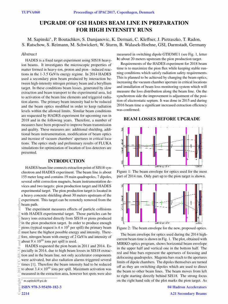
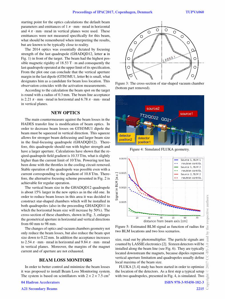
UPGRADE OF GSI HADES BEAM LINE IN PREPARATION FOR HIGH INTENSITY RUNS M. Sapinski * , P. Boutachkov, S. Damjanovic, K. Dermati, C. Kleffner, J. Pietraszko, T. Radon, S. Ratschow, S. Reimann, M. Schwickert, W. Sturm, B. Walasek-Hoehne, GSI, Darmstadt, Germany Abstract HADES is a fixed target experiment using SIS18 heavy- ion beams. It investigates the microscopic properties of matter formed in heavy-ion, proton and pion - induced reac- tions in the 1-3.5 GeV/u energy regime. In 2014 HADES used a secondary pion beam produced by interaction be- tween high-intensity nitrogen primary beam and a beryllium target. In these conditions beam losses, generated by slow extraction and beam transport to the experimental area, led to activation of the beam line elements and triggered radia- tion alarms. The primary beam intensity had to be reduced and the beam optics modified in order to keep radiation levels within the allowed limits. Similar beam conditions are requested by HADES experiment for upcoming run in 2018 and in the following years. Therefore, a number of measures have been proposed to improve beam transmission and quality. These measures are: additional shielding, addi- tional beam instrumentation, modification of beam optics and increase of vacuum chambers’ apertures in critical loca- tions. The optics study and preliminary results of FLUKA simulations for optimization of location of loss detectors are presented. INTRODUCTION HADES beam line connects extraction point of SIS18 syn- chrotron and HADES experiment. The beam line is about 155 meter long and contains 19 main quadrupoles, 7 dipoles, several orbit correction magnets, beam instrumentation de- vices and two targets: pion production target and HADES experimental target. The pion production target is located in a heavy concrete shielding about 30 meters upstream of the experiment. This target can be remotely removed from the beam path. The experiment measures effects of particle collisions with HADES experimental target. Those particles can be heavy ions extracted directly from SIS18 or pions produced in the pion production target. In order to produce enough pions (typical request is 4 × 10 5 per spill) the primary beam must have the highest possible energy and intensity. There- fore, nitrogen beam with energy of 2 GeV/u and intensity of about 9 × 10 10 ions per spill is used. HADES requested the pion beam in 2011 and 2014. Es- pecially in 2014, due to high beam losses in SIS18 extrac- tion and in the beam line, not only accelerator components were activated, but also radiation alarms triggered several times [1]. Therefore the beam intensity had to be reduced to about 3.4 × 10 10 ions per spill. Maximum activation was measured in the extraction area, however hot spots were also * [email protected] measured in switching dipole GTH3MU1 (see Fig. 1, letter b) about 20 meters upstream the pion production target. Requirements of the HADES experiment for 2018 beam time is to maximize the pion flux while keeping stable run- ning conditions which satisfy radiation safety requirements. This is planned to be achieved by changing the beam optics, increasing the vacuum chamber aperture in critical locations and installation of beam loss monitoring system which will measure the loss distribution along the beam line. On the synchrotron side the improvement is adjustment of the posi- tion of electrostatic septum. It was done in 2015 and during 2016 beam time a significant increased extraction efficiency was confirmed. BEAM LOSSES BEFORE UPGRADE Figure 1: The beam envelope for optics used for the most part of 2014 run. Only part up to the pion target is shown. Figure 2: The beam envelope for the new, proposed optics. The beam envelope for optics used during the 2014 high- current beam time is shown in Fig. 1. The plot, obtained with MIRKO optics program, shows horizontal beam envelope in the upper half and vertical one in the bottom half. The red and blue bars represent the apertures of focusing and defocusing quadrupoles. Magenta bars reach to the apertures limits of dipole chambers. The dipoles themselves are turned off as they are switching dipoles which are used to direct the beam to other beam lines. The beam moves from left to right starting directly behind SIS18. The strong focus on the right hand side of the plot marks the pion target. As TUPVA060 Proceedings of IPAC2017, Copenhagen, Denmark ISBN 978-3-95450-182-3 2214 Copyright © 2017CC-BY-3.0 and by the respective authors 04 Hadron Accelerators A21 Secondary Beams
Transcript of Upgrade of GSI HADES Beamline in Preparation for High...
UPGRADE OF GSI HADES BEAM LINE IN PREPARATIONFOR HIGH INTENSITY RUNS
M. Sapinski∗, P. Boutachkov, S. Damjanovic, K. Dermati, C. Kleffner, J. Pietraszko, T. Radon,S. Ratschow, S. Reimann, M. Schwickert, W. Sturm, B. Walasek-Hoehne, GSI, Darmstadt, Germany
AbstractHADES is a fixed target experiment using SIS18 heavy-
ion beams. It investigates the microscopic properties ofmatter formed in heavy-ion, proton and pion - induced reac-tions in the 1-3.5 GeV/u energy regime. In 2014 HADESused a secondary pion beam produced by interaction be-tween high-intensity nitrogen primary beam and a berylliumtarget. In these conditions beam losses, generated by slowextraction and beam transport to the experimental area, ledto activation of the beam line elements and triggered radia-tion alarms. The primary beam intensity had to be reducedand the beam optics modified in order to keep radiationlevels within the allowed limits. Similar beam conditionsare requested by HADES experiment for upcoming run in2018 and in the following years. Therefore, a number ofmeasures have been proposed to improve beam transmissionand quality. These measures are: additional shielding, addi-tional beam instrumentation, modification of beam opticsand increase of vacuum chambers’ apertures in critical loca-tions. The optics study and preliminary results of FLUKAsimulations for optimization of location of loss detectors arepresented.
INTRODUCTIONHADES beam line connects extraction point of SIS18 syn-
chrotron and HADES experiment. The beam line is about155 meter long and contains 19 main quadrupoles, 7 dipoles,several orbit correction magnets, beam instrumentation de-vices and two targets: pion production target and HADESexperimental target. The pion production target is located ina heavy concrete shielding about 30 meters upstream of theexperiment. This target can be remotely removed from thebeam path.The experiment measures effects of particle collisions
with HADES experimental target. Those particles can beheavy ions extracted directly from SIS18 or pions producedin the pion production target. In order to produce enoughpions (typical request is 4 × 10⁵ per spill) the primary beammust have the highest possible energy and intensity. There-fore, nitrogen beam with energy of 2 GeV/u and intensity ofabout 9 × 10¹⁰ ions per spill is used.HADES requested the pion beam in 2011 and 2014. Es-
pecially in 2014, due to high beam losses in SIS18 extrac-tion and in the beam line, not only accelerator componentswere activated, but also radiation alarms triggered severaltimes [1]. Therefore the beam intensity had to be reducedto about 3.4 × 10¹⁰ ions per spill. Maximum activation wasmeasured in the extraction area, however hot spots were also∗ [email protected]
measured in switching dipole GTH3MU1 (see Fig. 1, letterb) about 20 meters upstream the pion production target.Requirements of the HADES experiment for 2018 beam
time is to maximize the pion flux while keeping stable run-ning conditions which satisfy radiation safety requirements.This is planned to be achieved by changing the beam optics,increasing the vacuum chamber aperture in critical locationsand installation of beam loss monitoring system which willmeasure the loss distribution along the beam line. On thesynchrotron side the improvement is adjustment of the posi-tion of electrostatic septum. It was done in 2015 and during2016 beam time a significant increased extraction efficiencywas confirmed.
BEAM LOSSES BEFORE UPGRADE
Figure 1: The beam envelope for optics used for the mostpart of 2014 run. Only part up to the pion target is shown.
Figure 2: The beam envelope for the new, proposed optics.The beam envelope for optics used during the 2014 high-
current beam time is shown in Fig. 1. The plot, obtained withMIRKO optics program, shows horizontal beam envelopein the upper half and vertical one in the bottom half. Thered and blue bars represent the apertures of focusing anddefocusing quadrupoles. Magenta bars reach to the apertureslimits of dipole chambers. The dipoles themselves are turnedoff as they are switching dipoles which are used to directthe beam to other beam lines. The beam moves from leftto right starting directly behind SIS18. The strong focuson the right hand side of the plot marks the pion target. As
TUPVA060 Proceedings of IPAC2017, Copenhagen, Denmark
ISBN 978-3-95450-182-32214Co
pyrig
ht©
2017
CC-B
Y-3.
0an
dby
ther
espe
ctiv
eaut
hors
04 Hadron AcceleratorsA21 Secondary Beams
starting point for the optics calculations the default beamparameters and emittances of 1 π · mm · mrad in horizontaland 4 π · mm · mrad in vertical planes were used. Theseemittances were not measured specifically for this beam,what should be remembered when interpreting the results,but are known to be typically close to reality.The 2014 optics was essentially dictated by focusing
strength of the last quadrupole (GHADQD12, letter a inFig. 1) in front of the target. The beam had the highest pos-sible magnetic rigidity of 18.53 T · m and consequently thelast quadrupole operated at the upper limit of its specification.From the plot one can conclude that the vertical aperturemargin in the last dipole (GTH3MU1, letter b) is small, whatdesignates him as a candidate for beam loss location. Thisobservation coincides with the activation measurements.According to the calculation the beam spot on the target
is round with a radius of 0.3mm. The beam line acceptanceis 2.21 π · mm · mrad in horizontal and 6.78 π · mm · mradin vertical planes.
NEW OPTICSThe main countermeasure against the beam losses in the
HADES transfer line is modification of beam optics. Inorder to decrease beam losses on GTH3MU1 dipole thebeam must be squeezed in vertical direction. This squeezeallows for stronger beam defocusing and larger beam sizein the final-focusing quadrupole (GHADQD12). There-fore, this quadrupole should run with higher strength andhave a larger aperture. Calculations have shown that the re-qired quadrupole field gradient is 10.33 T/m, what is slightlyhigher than the current limit of 10 T/m. Powering test hasbeen done with the throttles in the cooling circuit removed.Stable operation of the quadrupole was possible even with acurrent corresponding to the gradient of 10.8 T/m. There-fore, the alternative focusing scheme presented in Fig. 2 isachievable for regular operation.The vertical beam size in the GHADQD12 quadrupole
is about 15% larger in the new optics as in the old one. Inorder to reduce beam losses in this area it was decided toconstruct star-shaped chambers which will be installed inboth quadrupoles (also in the preceeding GHADQD11 inwhich the horizontal beam size will increase by 50%). Thecross-section of these chambers, shown in Fig. 3, enlargesthe geometrical aperture in horizontal and vertical directionsfrom 60 mm to 98 mm.
The changes of optics and vacuum chambers geometry notonly reduce the beam losses, but also reduce the beam spotsize down to 0.22mm. In addition the acceptance increasesto 2.54 π · mm · mrad in horizontal and 9.84 π · mm · mradin vertical planes. Moreover, the margins of the magnetcurrent and of aperture are not exhausted.
BEAM LOSS MONITORSIn order to better control and minimize the beam losses
it was proposed to install Beam Loss Monitoring system.The system is based on scintillators with 2 × 2 × 7.5 cm3
Figure 3: The cross-section of star-shaped vacuum chamber(bottom part removed).
Figure 4: Simulated FLUKA geometry.
Figure 5: Estimated BLM signal as function of radius fortwo BLM locations and two loss scenarios.
size, read out by photomultiplier. The particle signals arecounted by LASSIE electronics [2]. Sixteen detectors will beinstalled along the beam line (see Fig. 6). They are typicallylocated downstream the magnets, because dipoles representvertical aperture limitation and quadrupoles usually definelocal maxima of the beam size.
FLUKA [3, 4] study has been started in order to optimizethe location of the detectors. As a first step a typical setupwith two quadrupoles, presented in Fig. 4, is simulated. Two
Proceedings of IPAC2017, Copenhagen, Denmark TUPVA060
04 Hadron AcceleratorsA21 Secondary Beams
ISBN 978-3-95450-182-32215 Co
pyrig
ht©
2017
CC-B
Y-3.
0an
dby
ther
espe
ctiv
eaut
hors
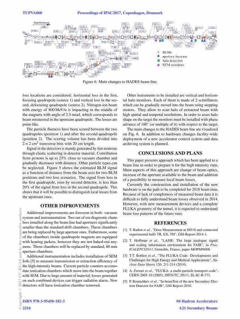
Figure 6: Main changes to HADES beam line.
loss locations are considered: horizontal loss in the first,focusing quadrupole (source 1) and vertical loss in the sec-ond, defocusing quadrupole (source 2). Nitrogen-ion beamwith energy of 800MeV/u is impacting in the middle ofthe magnets with angle of 2.5mrad, which corresponds tobeam missteered in the upstream quadrupole. The losses arepoint-like.The particle fluences have been scored between the two
quadrupoles (position 1) and after the second quadrupole(position 2). The scoring volume has been divided into2 × 2 cm2 transverse bins with 20 cm length.
Signal in the detectors is mainly generated by fast neutronsthrough elastic scattering in detector material. Contributionfrom protons is up to 25% close to vacuum chamber andgradually decreases with distance. Other particle types canbe neglected. Figure 5 shows the estimated BLM signalas a function of distance from the beam axis for two BLMpositions and two loss scenarios. The signal from loss inthe first quadrupole, seen by second detector, is less than20% of the signal from loss in the second quadrupole. Thisshows that it will be possible to distinguish local losses fromthe upstream ones.
OTHER IMPROVEMENTSAdditional improvements are foreseen in both: vacuum
system and instrumentation. Two out of ten diagnostic cham-bers installed along the beam line had apertures significantlysmaller than the standard drift chambers. These chambersare being replaced by large aperture ones. Futhermore, someof the chambers inside quadrupole magnets are equippedwith heating jackets, however they are not baked-out any-more. Those chambers will be replaced by standard, 60 mmaperture chambers.Additional instrumentation includes installation of SEM
foils [5] to measure transmission or extraction efficiency ofthe high-intensity beams. Current particle counters accomo-date ionization chambers which move into the beam togetherwith SEM. Due to large amount of material, losses generatedon such combined devices can trigger radiation alarm. Newdetectors will have ionization chamber removed.
Other instruments to be installed are vertical and horizon-tal halo monitors. Each of them is made of 2 scintillatorswhich can be gradually moved into the beam using steppingmotors. They allow to scan halo of extracted beam withhigh spatial and temporal resolutions. In order to asses haloshape on the target the monitors must be installed with phaseadvance of 180◦ (or multiple of it) with respect to the target.
The main changes to the HADES beam line are visualizedon Fig. 6. In addition to hardware changes facility-widedeployment of a new accelerator control system and dataarchiving system is planned.
CONCLUSIONS AND PLANSThis paper presents approach which has been applied to a
beam line in order to prepare it for the high intensity runs.Main aspects of this approach are change of beam optics,increase of the aperture available to the beam and additionof a possibility to measure local beam losses.Currently the construction and installation of the new
hardware is on the path to be completed for 2018 beam time.Because of lack of completness of measured beam data it isdifficult to fully understand beam losses observed in 2014.However, with new measurement devices and a completeFLUKA geometry of the tunnel, it is expected to understandbeam loss patterns of the future runs.
REFERENCES[1] T. Radon et al., "Dose Measurement at SIS18 and connected
experimental halls TR, EX, TH", GSI-Report-2014-1.
[2] T. Hoffman et al., "LASIE: The large analogue signaland scaling information environment for FAIR", in Proc.ICALEPCS2011, Grenoble, France, paper MOPMN008.
[3] T.T. Bohlen et al., "The FLUKA Code: Developments andChallenges for High Energy and Medical Applications", Nu-clear Data Sheets 120, 211-214 (2014).
[4] A. Ferrari et al., "FLUKA: a multi-particle transport code",CERN-2005-10 (2005), INFN/TC_05/11, SLAC-R-773.
[5] P. Boutachkov et al., "In-beamTest of the new Secondary Elec-tron Detector for FAIR", GSI-Report-2016.
TUPVA060 Proceedings of IPAC2017, Copenhagen, Denmark
ISBN 978-3-95450-182-32216Co
pyrig
ht©
2017
CC-B
Y-3.
0an
dby
ther
espe
ctiv
eaut
hors
04 Hadron AcceleratorsA21 Secondary Beams