
Updated December 2010 - LP DAAC :: NASA Land Data … · 2017-10-30 ·...
49
MODIS Reprojection Tool Swath User Manual Release 2.2 November 2010 Updated December 2010 Land Processes Distributed Active Archive Center USGS Earth Resources Observation and Science Center MRTSwath_Users_Manual_2.2_Dec2010.docx Page 1 12/3/2010
Transcript of Updated December 2010 - LP DAAC :: NASA Land Data … · 2017-10-30 ·...
MODIS Reprojection Tool Swath
User Manual
Release 2.2 November 2010 Updated December 2010
Land Processes Distributed Active Archive Center USGS Earth Resources Observation and Science Center
MRTSwath_Users_Manual_2.2_Dec2010.docx Page 1 12/3/2010

Table of Contents Table of Contents................................................................................................................ 2 Introduction......................................................................................................................... 4 MRTSwath Capabilities...................................................................................................... 6
Platforms.................................................................................................................................................... 6 Interfaces ................................................................................................................................................... 6 Data Products............................................................................................................................................. 6 Source Information .................................................................................................................................... 6 Spectral Subsetting .................................................................................................................................... 6 Spatial Subsetting ...................................................................................................................................... 7 File Formats............................................................................................................................................... 7 Map Projections......................................................................................................................................... 7 Datum Conversions ................................................................................................................................... 7 Resampling ................................................................................................................................................ 7 Data Types................................................................................................................................................. 7 Output Pixel Size ....................................................................................................................................... 8 Corner Coordinates.................................................................................................................................... 8 Parameter Files .......................................................................................................................................... 8 Log File ..................................................................................................................................................... 9 Metadata .................................................................................................................................................... 9
MRTSwath Installation..................................................................................................... 10 Automatic Installation ............................................................................................................................. 11 Manual Installation .................................................................................................................................. 12
Manual Installation Instructions for UNIX Platforms......................................................................... 12 Manual Installation Instructions for Windows Platforms ................................................................... 15
Adding a Shortcut Icon in Windows........................................................................................................ 17 MODIS Reprojection Tool Swath Command Line Interface ........................................... 19
Batch Processing Options ........................................................................................................................ 23 Batch Files ............................................................................................................................................... 23 UNIX Bourne Shell ................................................................................................................................. 24 Command Line Arguments...................................................................................................................... 24 Automated Batch Processing ................................................................................................................... 25
MRTSwath GUI................................................................................................................ 27 Obtaining Geolocation Files .................................................................................................................... 28 Opening an Input File .............................................................................................................................. 29 Metadata Examination ............................................................................................................................. 30 Spectral Subsetting .................................................................................................................................. 31 Spatial Subsetting .................................................................................................................................... 31 Opening a Geolocation File ..................................................................................................................... 32 Specify Output File.................................................................................................................................. 33 Output File Type...................................................................................................................................... 34 Resampling Type..................................................................................................................................... 34 Output Projection Type............................................................................................................................ 35 Output Data Type .................................................................................................................................... 36 Output Pixel Size ..................................................................................................................................... 36 Load or Save Parameter File.................................................................................................................... 36 Executing swath2grid ........................................................................................................................ 37 Exiting MRTSwath.................................................................................................................................. 38
Contacts............................................................................................................................. 39 Appendix A: MRTSwath Parameter File Format ............................................................. 40
File naming conventions.......................................................................................................................... 40 Parameter file format ............................................................................................................................... 40
MRTSwath_Users_Manual_2.2_Dec2010.docx Page 2 12/3/2010
Appendix B: MRTSwath Raw Binary File Format .......................................................... 44 File naming conventions.......................................................................................................................... 44 Header file format.................................................................................................................................... 44 Notes........................................................................................................................................................ 45
Appendix C: Projection Parameters.................................................................................. 46
MRTSwath_Users_Manual_2.2_Dec2010.docx Page 3 12/3/2010

Introduction The Moderate Resolution Imaging Spectroradiometer (MODIS)1 provides a comprehensive series of land, ocean, and atmosphere observations used to study global change. With a more frequent overpass than Landsat (near-daily) and higher spatial resolution than its predecessors (250-, 500-, and 1,000-meter), MODIS provides valuable data sets used to study a number of environmental issues. MODIS products are distributed in Hierarchical Data Format for Earth Observing System (HDF-EOS)2 , and are provided either on a standard mapping grid (levels-2G, -3, and -4) or in their native swath form (levels-1 and 2). When the MODIS mission began in 1999, users were immediately challenged by the file format, the standard map projection, or the lack of map projection in these products. In response, the Land Processes Distributed Active Archive Center (LP DAAC) and the South Dakota School of Mines & Technology collaborated in developing conversion and reprojection tools using software written by the MODIS Land Science Team3. The MODIS Reprojection Tool (MRT) was developed to support manipulation of higher level MODIS Land product tiles, which were cast on an Integerized Sinusoidal mapping grid in Version 1, but have since been produced as Sinusoidal tiles (Versions 3-6). The use of the MRT is described in a separate document available from the LP DAAC Tools Web site4. The MODIS Reprojection Tool Swath (MRTSwath) application was developed to process lower level MODIS swath products, specifically those archived at LP DAAC (MOD11_L2, MYD11_L2, MOD14, and MYD14)5. Its success with other data types (such as level-1B radiance data and certain atmospheric products) is somewhat coincidental and is not guaranteed. The heart of the MRTSwath is the swath2grid executable, which may be run either from a Graphical User Interface (GUI) or in command line mode. The GUI is a self-guiding, user-friendly way to run the MRTSwath when only a few files need to be processed. Otherwise, users are advised to investigate the more powerful command line interface, particularly when used in conjunction with the automated batch processing scripts included in this package. The combination enables automated parameter builds and background processing of lengthy job sequences (e.g., this is recommended for projection of swath products in a time series).
1 More information about MODIS may be obtained from http://modis.gsfc.nasa.gov/. 2 More information on HDF and HDF-EOS may be obtained from http://hdf.ncsa.uiuc.edu and http://hdfeos.gsfc.nasa.gov respectively 3 resample.exe and swath2grid.exe courtesy of MODIS Land Science Team, Robert Wolfe and Sadashiva Devadiga 4 More information on MODIS tools may be obtained from https://lpdaac.usgs.gov/lpdaac/tools/. 5 MOD11_L2 MODIS/Terra Land Surface Temperature/Emissivity 5-Min L2 Swath 1km; MYD11_L2 MODIS/Aqua Land Surface Temperature/Emissivity 5-Min L2 Swath 1km; MOD14 MODIS/Terra Thermal Anomalies/Fire 5-Min L2 Swath 1km; MYD14 MODIS/Aqua Thermal Anomalies/Fire 5-Min L2 Swath 1km
MRTSwath_Users_Manual_2.2_Dec2010.docx Page 4 12/3/2010

This User Manual describes how to run MRTSwath in command line and GUI mode, with special instruction for the new automated batch processing.
MRTSwath_Users_Manual_2.2_Dec2010.docx Page 5 12/3/2010

MRTSwath Capabilities Platforms The MRTSwath application is portable software available for four different platforms. Windows Linux 32-bit Linux 64-bit Macintosh Interfaces Users may invoke MRTSwath either from a user-friendly GUI or from a powerful command line interface. The GUI allows novices and users with light processing requirements to project MODIS swath data (levels-1 and -2). The GUI also allows easy inspection of metadata. The scriptable command line interface, with its variety of command line options, is recommended for projecting large numbers of files. Data Products MRTSwath was designed specifically to accommodate projection of LP DAAC MODIS swath products (MOD11_L2, MYD11_L2, MOD14, and MYD14)5. Its success with other data types (such as level-1B radiance data and certain atmospheric products) is somewhat coincidental and is not guaranteed. All projections require the additional input of the corresponding MODIS Geolocation file (MOD03, MYD03)6. MRTSwath support includes conversion of multidimensional products (i.e., MOD02). 3D data products are extracted to 2D outputs in a variety of file formats using the following naming convention: <SDS name>.<3rd dimension name>_b# where # is a value (starting at 0) representing the data slice for the 3rd dimension. Source Information MRTSwath extracts useful information from the input file and in GUI mode displays basic file specifications to the user, including the number of bands available, data type, numbers of lines and samples, and the upper left and lower right corners. Spectral Subsetting Any subset of the input HDF-EOS Science Data Sets, labeled as “bands” in the MRTSwath, may be selected for projection. The default is to project all input bands, with the exception of bands that do not conform to the nominal MODIS scan size (2030x1354). MRTSwath may not recognize such bands (eg., fire pixel table) when opening the input file, and will trigger an error message for that band while continuing to process any other specified bands.
6 MODIS Geolocation data files are available from the Level 1 and Atmosphere Archive and Distribution System (LAADS) http://ladsweb.nascom.nasa.gov/.
MRTSwath_Users_Manual_2.2_Dec2010.docx Page 6 12/3/2010

Spatial Subsetting A spatial subset is defined by entering two corners (upper left and lower right) of a rectangle. These corners are specified either as input latitude and longitude coordinates, as input line/sample pairs, or as output projection coordinates. The default is to project the entire input image, using the bounding rectangular coordinates from the global attributes metadata. File Formats MODIS swath HDF-EOS files are supported as input. HDF-EOS, georeferenced tagged image file format (GeoTIFF), and raw binary files are supported for output. The raw binary file format is specified in Appendix B. Map Projections MRTSwath uses calls to the General Cartographic Transformation Package (GCTP) and as such allows projection to the following mapping grids. Albers Equal Area Equirectangular Geographic Hammer Integerized Sinusoidal Interrupted Goode Homolosine Lambert Azimuthal Lambert Conformal Conic Mercator Mollweide Polar Stereographic Sinusoidal Transverse Mercator Universal Transverse Mercator The GCTP used by MRTSwath applications was modified to incorporate the Integerized Sinusoidal Projection originally applied to Version 001 MODIS products. Datum Conversions Datum conversions are not supported by MRTSwath applications. Resampling Three resampling methods are available in MRTSwath: nearest neighbor, bilinear, and cubic convolution. Data Types The MRTSwath supports character data and 8-, 16-, and 32-bit integer data (both signed and unsigned). Unless specified by the user, the default output data type will match that of the input.
MRTSwath_Users_Manual_2.2_Dec2010.docx Page 7 12/3/2010
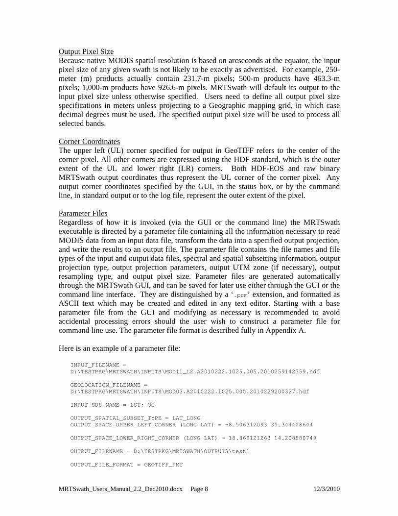
Output Pixel Size Because native MODIS spatial resolution is based on arcseconds at the equator, the input pixel size of any given swath is not likely to be exactly as advertised. For example, 250-meter (m) products actually contain 231.7-m pixels; 500-m products have 463.3-m pixels; 1,000-m products have 926.6-m pixels. MRTSwath will default its output to the input pixel size unless otherwise specified. Users need to define all output pixel size specifications in meters unless projecting to a Geographic mapping grid, in which case decimal degrees must be used. The specified output pixel size will be used to process all selected bands. Corner Coordinates The upper left (UL) corner specified for output in GeoTIFF refers to the center of the corner pixel. All other corners are expressed using the HDF standard, which is the outer extent of the UL and lower right (LR) corners. Both HDF-EOS and raw binary MRTSwath output coordinates thus represent the UL corner of the corner pixel. Any output corner coordinates specified by the GUI, in the status box, or by the command line, in standard output or to the log file, represent the outer extent of the pixel. Parameter Files Regardless of how it is invoked (via the GUI or the command line) the MRTSwath executable is directed by a parameter file containing all the information necessary to read MODIS data from an input data file, transform the data into a specified output projection, and write the results to an output file. The parameter file contains the file names and file types of the input and output data files, spectral and spatial subsetting information, output projection type, output projection parameters, output UTM zone (if necessary), output resampling type, and output pixel size. Parameter files are generated automatically through the MRTSwath GUI, and can be saved for later use either through the GUI or the command line interface. They are distinguished by a ‘.prm’ extension, and formatted as ASCII text which may be created and edited in any text editor. Starting with a base parameter file from the GUI and modifying as necessary is recommended to avoid accidental processing errors should the user wish to construct a parameter file for command line use. The parameter file format is described fully in Appendix A. Here is an example of a parameter file:
INPUT_FILENAME = D:\TESTPKG\MRTSWATH\INPUTS\MOD11_L2.A2010222.1025.005.2010259142359.hdf GEOLOCATION_FILENAME = D:\TESTPKG\MRTSWATH\INPUTS\MOD03.A2010222.1025.005.2010229200327.hdf INPUT_SDS_NAME = LST; QC OUTPUT_SPATIAL_SUBSET_TYPE = LAT_LONG OUTPUT_SPACE_UPPER_LEFT_CORNER (LONG LAT) = -8.506312093 35.344408644 OUTPUT_SPACE_LOWER_RIGHT_CORNER (LONG LAT) = 18.869121263 14.208880749 OUTPUT_FILENAME = D:\TESTPKG\MRTSWATH\OUTPUTS\test1 OUTPUT_FILE_FORMAT = GEOTIFF_FMT
MRTSwath_Users_Manual_2.2_Dec2010.docx Page 8 12/3/2010
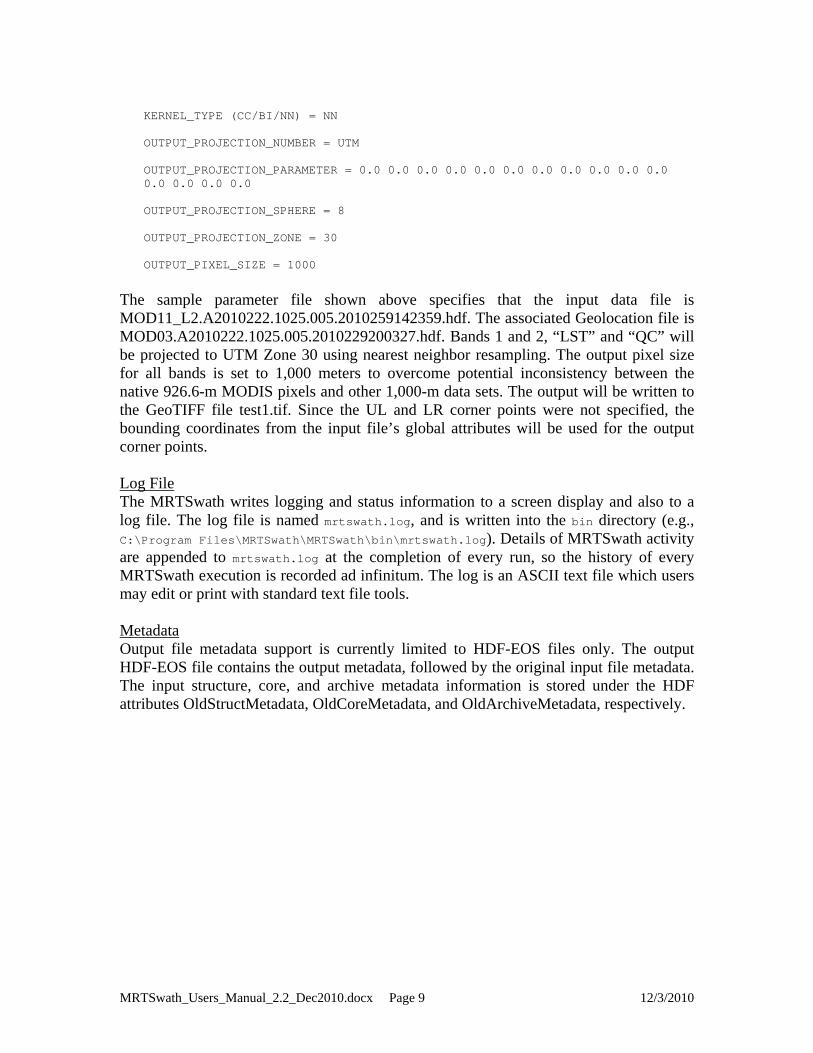
KERNEL_TYPE (CC/BI/NN) = NN OUTPUT_PROJECTION_NUMBER = UTM OUTPUT_PROJECTION_PARAMETER = 0.0 0.0 0.0 0.0 0.0 0.0 0.0 0.0 0.0 0.0 0.0 0.0 0.0 0.0 0.0 OUTPUT_PROJECTION_SPHERE = 8 OUTPUT_PROJECTION_ZONE = 30 OUTPUT_PIXEL_SIZE = 1000
The sample parameter file shown above specifies that the input data file is MOD11_L2.A2010222.1025.005.2010259142359.hdf. The associated Geolocation file is MOD03.A2010222.1025.005.2010229200327.hdf. Bands 1 and 2, “LST” and “QC” will be projected to UTM Zone 30 using nearest neighbor resampling. The output pixel size for all bands is set to 1,000 meters to overcome potential inconsistency between the native 926.6-m MODIS pixels and other 1,000-m data sets. The output will be written to the GeoTIFF file test1.tif. Since the UL and LR corner points were not specified, the bounding coordinates from the input file’s global attributes will be used for the output corner points. Log File The MRTSwath writes logging and status information to a screen display and also to a log file. The log file is named mrtswath.log, and is written into the bin directory (e.g., C:\Program Files\MRTSwath\MRTSwath\bin\mrtswath.log). Details of MRTSwath activity are appended to mrtswath.log at the completion of every run, so the history of every MRTSwath execution is recorded ad infinitum. The log is an ASCII text file which users may edit or print with standard text file tools. Metadata Output file metadata support is currently limited to HDF-EOS files only. The output HDF-EOS file contains the output metadata, followed by the original input file metadata. The input structure, core, and archive metadata information is stored under the HDF attributes OldStructMetadata, OldCoreMetadata, and OldArchiveMetadata, respectively.
MRTSwath_Users_Manual_2.2_Dec2010.docx Page 9 12/3/2010

MRTSwath Installation To obtain the MRTSwath software, users are required to create an account on the LP DAAC Tools Web site4, a quick process that will enable notifications of software-related information (such as new releases). After successful login, users can download the appropriate platform-specific MRTSwath zip file from the same site. The MRTSwath software is delivered in MRTSwath_download_<platform>.zip that needs to be unzipped before installation. After the software files are extracted from the zip package, the software can be installed with either an automatic or a manual installation process. The automatic installation process is recommended for most users, but instructions for both methods are outlined below. NOTE to users with previously installed MRTSwath software: Users no longer need to carefully place software or files in directories with no spaces in their path names, as required by previous MRTSwath versions. As of version 2.2, MRTSwath will install and run in any specified directory. This applies to both the MRT and Java directories. Further related to directory paths, it is also no longer necessary to use forward slashes (/) instead of backslashes (\) during MRTSwath installation to Windows platforms. Backslashes are in fact now recommended when entering directory paths during installation. Otherwise, there are a couple of pre-install checks that users are encouraged to address to ensure successful installation and execution of the MRTSwath. First note that entry of full pathnames during installation is highly recommended for all directories. Wildcards (?,*) and relative pathnames are accepted, but the MRTSwath software is not guaranteed to set up correctly. Second, in order to run the MRTSwath GUI, installation of a current version of Java7
is required (at least the Java 2 Runtime Environment version 1.5 or the Java 2 SDK version 1.5 or later). If the only intent is to use the command line interface, Java is not necessary and this requirement can be ignored, but GUI operations will not execute without a current Java version. The Java directory path is needed during the installation process, so have this information available during installation. On Windows platforms, Start/Search can be used to locate the Java directories on the system. On UNIX-based systems such as Linux and Macintosh, type which java to determine the path to the existing Java executable. This method will work only if the Java executable is on the current path. Typing find / -name java will also work, but this will search all mounted file systems and may take time to complete. If necessary, ask a system administrator where the Java bin directory is located.
7 Java software for all platforms may be downloaded from the Oracle Web site at http://www.oracle.com/technetwork/java/javase/overview/index.html.
MRTSwath_Users_Manual_2.2_Dec2010.docx Page 10 12/3/2010

If the Java executable is on the current path, the version of Java installed on the machine can be determined by typing java –version, which will output something similar to this:
java version "1.5.0"
If the version number is older than 1.5.0, the MRTSwath GUI is not guaranteed to work. In this case, installing a newer Java version is recommended. Automatic Installation 1. Step one to automatically installing the MRTSwath to either Windows or UNIX
systems (Linux or Macintosh) is unzipping the MRTSwath_download_<platform>.zip file.
2. Step two is to collect the following information to facilitate successful and efficient installation.
The complete pathname of the directory in which MRTSwath will be installed
(full pathnames are recommended over wildcards). The default will create a MRTSwath subdirectory in the current directory, but users have the option to enter a different directory path if preferred.
The pathname of the directory containing the Java executable program (java or java.exe). This pathname is not necessary on UNIX platforms if the Java executable is on the current path, in which case it will be found automatically. See the information at the start of the Installation section for hints on how to determine the location of the Java bin directory.
3. Step three is using a command line interface to navigate to the directory in which MRTSwath_download_<platform>.zip was unzipped. It will contain the files install.bat, MRTSwath_<platform>.zip, reg_set.exe, and unzip.exe.
4. Step four is to execute the install scripts while within the directory containing the installation files (see previous step).
For UNIX (Linux or Macintosh), type ./install, such as:
[user@server /MRTSwath]$ ./install
For Windows, type install, from the Command Prompt screen invoked from
Start\Programs\Accessories.
C:\Program Files\MRTSwath> install
5. Step five is to carefully follow the instructions appearing in response to the install
command. The program will prompt the user to enter a preferred location for the install, and the information needed to set up path and environment variables correctly. Providing full pathnames for all directories is advised because although wildcards
MRTSwath_Users_Manual_2.2_Dec2010.docx Page 11 12/3/2010
6. Step six is a recommended system or session restart to ensure the changes made
during MRTSwath installation take effect. Manual Installation Three steps are required for manual installation of the MRTSwath: Unzip the software. Update the system variables to include PATH, MRTSWATH_HOME, and
MRTSWATH_DATA_DIR information for MRTSwath. Edit the GUI script in the MRTSwath bin directory to reflect the system directory
structure. Below are instructions for manually working through these steps. The first section is relevant to UNIX systems and includes specifics for C shell and Bourne shell. The second section is relevant to Windows systems and includes specifics for 95/98/2000 and NT/ME/XP. Manual Installation Instructions for UNIX Platforms 1. Step one for manual installation of the MRTSwath to a UNIX-based system such as
Linux or Macintosh is a two-part extraction process to load the necessary files to the user’s system. First, unzip the MRTSwath_download_<platform>.zip file downloaded from the LP DAAC Tools Web site. Use the command ./unzip from a UNIX terminal to inflate the download package to a chosen location.
./unzip zipfile –d “MRTSwathdownload_directory”
where zipfile is MRTSwath_download_Linux.zip (32-bit compilation), MRTSwath_ download_Linux64.zip (64-bit compilation), or MRTSwath_download_Mactel.zip (Macintosh compilation), and MRTSwathdownload_directory is the directory to which the zip contents will be extracted. Changing to the MRTSwathdownload_directory in the UNIX terminal, the file install should be present along with either MRTSwath_Linux.zip, MRTSwath_Linux64.zip, or MRTSwath_Mactel.zip. The second part of the extraction process will inflate the MRTSwath software package. Use the unzip command to extract the installation software to a chosen location.
unzip zipfile –d “MRTSwath_directory”
MRTSwath_Users_Manual_2.2_Dec2010.docx Page 12 12/3/2010
where zipfile is MRTSwath_Linux.zip, MRTSwath_Linux64.zip, or MRTSwath
_Mactel.zip, and MRTSwath_directory is the directory into which MRTSwath will be installed. For example, to install the MRTSwath in the MRTSwath subdirectory in the home directory on a Linux workstation, type the following.
unzip MRTSwath_Linux.zip –d “$HOME/My MRTSwath”
If an error is returned saying “unzip: command not found”, try using a preceding “./” as shown below.
./unzip MRT_Linux.zip –d “$HOME/My MRTSwath”
2. Step two will add MRTSwath information to the startup files for the current shell
(csh, tcsh, sh, bash). Typing echo $0 or echo $SHELL at the command prompt will display which shell is being used. C shell (csh, tcsh) users will need to add or update the path, MRTSWATH_HOME, and MRTSWATH_DATA_DIR environment variables to the system .login file in the home directory. Assuming installation of MRTSwath in a My MRTSwath subdirectory in the home directory, the following lines are appended to the .login.
set path = ( $path:q “$HOME/My MRTSwath/bin” ) setenv MRTSWATH_DATA_DIR “$HOME/My MRTSwath/data” setenv MRTSWATH_HOME “$HOME/My MRTSwath”
Bourne shell (sh, bash) users will likewise add or update the path, MRTSWATH_HOME, and MRTSWATH_DATA_DIR environment variables to the system .profile and .bash_profile file in the home directory, in addition to setting the path to the Java executable. The following lines are appended to .profile or .bash_profile files in the home directory.
#!/bin/sh PATH=”$PATH:$HOME/My MRTSwath/bin” MRTSWATH_DATA_DIR=”$HOME/My MRTSwath/data” MRTSWATH_HOME=”$HOME/MRTSwath“ export MRTSWATH_HOME PATH MRTSWATH_DATA_DIR
Note that the final statement starting with "<path_to_java_bin>/java…” is all on one line. Do not break this statement into multiple lines. These changes will not take effect without restarting a new login session. Also be aware that each new installation will append the environment variable statements to the startup files, so it is advisable to remove these lines prior to a new install.
3. In step 3, the ModisSwathTool shell script used to run the MRTSwath GUI is created manually. This script will configure the variables PATH, MRTSWATH_HOME, and MRTSWATH_DATA_DIR. The ModisSwathTool script can be generated in any text editor and should be saved to the MRTSwath bin directory. Below is an example that can
MRTSwath_Users_Manual_2.2_Dec2010.docx Page 13 12/3/2010

Make sure to replace all directory information in the template to reflect the structure of the host machine. Note that the final statement indicating the Java path is all on one line. Do not break this statement into multiple lines. Save the file in the bin (e.g., c:\Program Files\MRTSwath\Tool\bin) as ModisSwathTool.bat.
A system restart is advised to ensure the changes made during MRTSwath installation take effect and the tools function as expected. C shell (csh, tcsh) ModisSwathTool template: #!/bin/sh # *********************************************** # * ModisSwathTool * # * C Shell script for running the MRTSwath GUI * # *********************************************** # Set the MRTSWATH_HOME environment variable to the MRTSwath installation directory. setenv MRTSWATH_HOME "$HOME/My MRTSwath" # Set the MRTSWATH_DATA_DIR environment variable to the data directory. setenv MRTSWATH_DATA_DIR "$HOME/My MRTSwath/data" # Set the PATH environment variable to include MRTSwath executables. set path = ( $path:q "$HOME/My MRTSwath/bin" ) # Run the MRTSwath Java GUI. "<path_to_java_bin>/java" -jar "$HOME/My MRTSwath/bin/ModisSwathTool.jar"
Bourne shell (sh, bash) ModisSwathTool template: #!/bin/sh # **************************************************** # * ModisSwathTool * # * Bourne Shell script for running the MRTSwath GUI * # **************************************************** # Set the MRTSWATH_HOME environment variable to the MRTSwath installation directory. MRTSWATH_HOME="$HOME/My MRTSwath" export MRTSWATH_HOME # Set the MRTSWATH_DATA_DIR environment variable to the data directory. MRTSWATH_DATA_DIR="$HOME/My MRTSwath/data"
MRTSwath_Users_Manual_2.2_Dec2010.docx Page 14 12/3/2010

export MRTSWATH_DATA_DIR # Set the PATH environment variable to include MRTSwath executables. PATH="$HOME/My MRTSwath/bin:$PATH" export PATH # Run the MRTSwath Java GUI. "<path_to_java_bin>/java" -jar "$HOME/My MRTSwath/bin/ModisSwathTool.jar"
Manual Installation Instructions for Windows Platforms On Windows platforms, note that it is no longer necessary to enter directory pathnames with forward slashes (/) instead of backslashes (\). It is in fact recommended that only backslashes are used during Windows installation. Neither is it necessary to avoid directories with blank spaces for the MRTSwath install directory, the Java directory, or the input file directory. 1. Step one for manual Windows installation is unzipping the MRTSwath software,
which is a two-part process. First unzip the MRTSwath software package downloaded from the LP DAAC Tools Web site (MRTSwath_download_Win.zip). This can be done automatically common tools like WinZip. For example, right click on the zip, select WinZip then Extract to, and create a directory for the enclosed files (such as C:\Program Files\MRTSwath). The MRTSwath_download_Win.zip will inflate to install.bat, MRTSwath_Win.zip, reg_set.exe, and unzip.exe. Second, the unzip.exe will be used to extract the files needed for installation from C:\Program Files\MRTSwath\MRTSwath_Win.zip. From Start\Programs\Accessories, open a Command Prompt screen, change to the directory containing the files just extracted (C:\Program Files\MRTSwath), and type the following command. unzip MRTSwath_Win.zip –d “MRTSwath_directory”
where MRTSwath_directory is the directory in which the MRTSwath will be finally installed. For example, to install the MRTSwath in C:\Program Files\MRTSwath
\Tool, type the command as follows. unzip MRTSwath_Win.zip –d “c:\Program Files\MRTSwath\Tool”
2. Step two is to update the system variables to recognize the PATH, MRTSWATH_HOME,
and MRTSWATH_DATA_DIR needed to run MRTSwath. Windows 95/98/2000 users must edit the AUTOEXEC.BAT file to add the path information and set the MRTSWATH_DATA_DIR variable. Using Notepad or some other text editor, add the following two lines to the end of the AUTOEXEC.BAT file:
PATH %PATH%;”c:\Program Files\MRTSwath\Tool\bin” set MRTSWATH_DATA_DIR=”c:\Program Files\MRTSwath\Tool\data” set MRTSWATH_HOME=”c:\Program Files\MRTSwath\Tool”
MRTSwath_Users_Manual_2.2_Dec2010.docx Page 15 12/3/2010
where c:\Program Files\MRTSwath\Tool was the directory chosen for MRTSwath installation. If the MRTSwath was installed in some other directory, then change these directory paths accordingly. Windows NT/ME/XP users must edit their user keys to add the MRTSwath PATH, MRTSWATH_HOME, and MRTSWATH_DATA_DIR to the system variables. Invoke a Command Prompt window from Start\Programs\Accessories and type regedit at the DOS prompt. This will bring up a GUI containing user key information. Double-click on the HKEY_CURRENT_USER key then click on the Environment key. The current user key environment variables and their values will be listed on the right hand side of the GUI. If the keys MRTSWATH_DATA_DIR, MRTSWATH_HOME, and PATH do not exist, go to the Registry Editor menu bar at the top of the GUI and click Edit. From there, select New then String Value to create a new user key. The keys for PATH, MRTSWATH_HOME, and MRTSWATH_DATA_DIR should be listed in the right pane of the Registry Editor. Each can be double-clicked to modify their values. Continuing with the above example, the PATH would be modified to add c:\Program Files\MRTSwath\Tool\bin to the end of the current string, entering a semi-colon to separate directories in the path. The MRTSWATH_HOME would be set to c:\Program Files\MRTSwath\Tool, and MRTSWATH_DATA_DIR would be set to c:\Program
Files\MRTSwath\Tool\data. It is recommended that any previous values specified for these keys are removed.
3. In step 3, the ModisSwathTool.bat script used to run the MRTSwath GUI is created manually. This script will configure the variables PATH, MRTSWATH_HOME, and MRTSWATH_DATA_DIR. The .bat can be generated in any text editor (such as Notepad), and should be saved to the MRTSwath bin directory. Below is an example that can be used as a template for creating this file. It assumes the directory structure used in the examples above. Make sure to replace all directory information in the template to reflect the structure of the host machine. Note that the final statement starting with “c:\Program Files\Java…” is all on one line. Do not break this statement into multiple lines. Save the file in the bin (e.g., c:\Program Files\MRTSwath\Tool\bin) as ModisSwathTool.bat.
A system restart is advised to ensure the changes made during MRTSwath installation take effect and the tools function as expected. @@echo off
MRTSwath_Users_Manual_2.2_Dec2010.docx Page 16 12/3/2010
rem ********************** rem * ModisSwathTool.bat * rem ********************** rem Set the MRTSWATH_HOME environment variable to the MRTSwath installation rem directory. set MRTSWATH_HOME=”C:\Program Files\MRTSwath\Tool” rem Set the MRTSWATH_DATA_DIR environment variable to the data directory. set MRTSWATH_DATA_DIR=”C:\Program Files\MRTSwath\Tool\data” rem Set the PATH environment variable to include the MRTSwath executables. set Path=”C:\Program Files\MRTSwath\Tool\bin” rem Run the Java GUI. rem Change the java.exe path to reflect the directory structure on host. rem Quotes are only necessary to handle blank spaces in the pathnames. ECHO is off. "c:\Program Files\Java\jre1.6.0_05\bin\java.exe" -jar "C:\Program Files\MRTSwath\Tool\bin\ModisSwathTool.jar"
Adding a Shortcut Icon in Windows The MRTSwath has an icon file in the Windows distribution package. It is located in the MRTSwath bin directory. A shortcut icon for the MRTSwath can be created and used on the Windows platforms. To create a shortcut icon follow these steps:
1. Click the right mouse button on the desktop 2. Select New Shortcut 3. Type in the path and name for the ModisSwathTool.bat file (or use the Browse
button to find the ModisSwathTool.bat file, which should be in the MRTSwath bin directory)
4. Select Next 5. Type a name for the shortcut (i.e. ModisSwathTool, MRTSwath, etc.) 6. Select Finish 7. Right click on the shortcut icon that was just created 8. Select Properties 9. Select the Shortcut tab 10. Press Change Icon 11. Type in the path and name for the ModisSwathTool.ICO file (or use the Browse
button to find the ModisSwathTool.ICO file, which should be in the MRTSwath bin directory)
12. Press OK The MRTSwath icon should now be available on the desktop. When the icon is double-clicked, the MRTSwath GUI should appear. Please note that the default directory when using the MRTSwath icon, because it points to the ModisSwathTool.bat file, will be the MRTSwath bin directory. Thus, the log file and MRTSwath temporary files will automatically be written to the MRTSwath bin directory.
MRTSwath_Users_Manual_2.2_Dec2010.docx Page 17 12/3/2010

MRTSwath_Users_Manual_2.2_Dec2010.docx Page 18 12/3/2010

MODIS Reprojection Tool Swath Command Line Interface This section of the User Manual describes how to run the MRTSwath from the command line. The command line version of the MRTSwath is invoked by running the swath2grid program. From the command prompt, typing swath2grid from the MRTSwath bin directory results in a brief usage message that lists various command line arguments used to execute MRTSwath. The last statement in the usage message will be an alert that no processing parameters were included in the command. Further direction for swath2grid parameters follows the usage example below.
*********************************************************** MODIS Reprojection Tool Swath (v2.2 October 2010) Start Time: Mon Oct 25 11:17:31 2010 ---------------------------------------------------------- usage: swath2grid -if=<input file> -of=<output file> -gf=<geolocation file> [-off=<output file format (HDF_FMT, GEOTIFF_FMT, RB_FMT)>] [-sds=<SDS name>] [-kk=<resampling type (NN, BI, CC)>] -oproj=<output projection> [-oprm=<output projection parameters>] [-opsz=<output pixel sizes>] [-oul=<output upper left corner>] [-olr=<output lower right corner>] [-ozn=<output zone number>] [-osst=<output spatial subset type (LAT_LONG, PROJ_COORDS, LINE_SAMPLE)>] [-osp=<output sphere number>] [-oty=<output data type>] [-pf=<parameter file>] For more information use swath2grid -help For general help on map projections and spheres use swath2grid -help=proj For help using the parameter file (-pf option) use swath2grid -help=param For help on a specific map projection use swath2grid -help=<projection>
error: [NeedHelp, parser.c:2131] : getting runtime parameters Terminating application ...
More specific help information on the swath2grid application is available by typing swath2grid –help or swath2grid –help=param. If using an input parameter file8 (recommended) the only required command line argument is the parameter file name. To run MRTSwath from the command line, type:
swath2grid –pf=<parameter_file>
8 See Appendix A for more information about the parameter file.
MRTSwath_Users_Manual_2.2_Dec2010.docx Page 19 12/3/2010
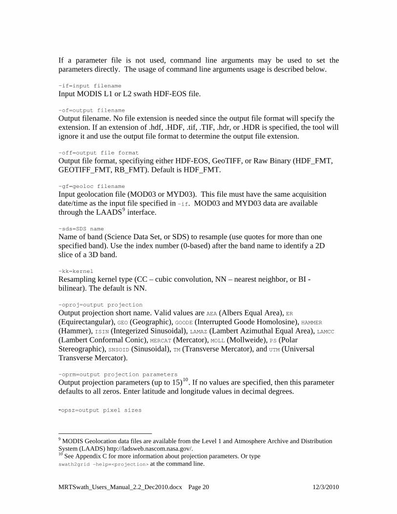
If a parameter file is not used, command line arguments may be used to set the parameters directly. The usage of command line arguments usage is described below. -if=input filename Input MODIS L1 or L2 swath HDF-EOS file. -of=output filename
Output filename. No file extension is needed since the output file format will specify the extension. If an extension of .hdf, .HDF, .tif, .TIF, .hdr, or .HDR is specified, the tool will ignore it and use the output file format to determine the output file extension. -off=output file format
Output file format, specifiying either HDF-EOS, GeoTIFF, or Raw Binary (HDF_FMT, GEOTIFF_FMT, RB_FMT). Default is HDF_FMT. -gf=geoloc filename
Input geolocation file (MOD03 or MYD03). This file must have the same acquisition date/time as the input file specified in –if. MOD03 and MYD03 data are available through the LAADS9 interface. -sds=SDS name
Name of band (Science Data Set, or SDS) to resample (use quotes for more than one specified band). Use the index number (0-based) after the band name to identify a 2D slice of a 3D band. -kk=kernel
Resampling kernel type (CC – cubic convolution, NN – nearest neighbor, or BI - bilinear). The default is NN. -oproj=output projection
Output projection short name. Valid values are AEA (Albers Equal Area), ER (Equirectangular), GEO (Geographic), GOODE (Interrupted Goode Homolosine), HAMMER (Hammer), ISIN (Integerized Sinusoidal), LAMAZ (Lambert Azimuthal Equal Area), LAMCC (Lambert Conformal Conic), MERCAT (Mercator), MOLL (Mollweide), PS (Polar Stereographic), SNSOID (Sinusoidal), TM (Transverse Mercator), and UTM (Universal Transverse Mercator). -oprm=output projection parameters
Output projection parameters (up to 15)10. If no values are specified, then this parameter defaults to all zeros. Enter latitude and longitude values in decimal degrees. -opsz=output pixel sizes
9 MODIS Geolocation data files are available from the Level 1 and Atmosphere Archive and Distribution System (LAADS) http://ladsweb.nascom.nasa.gov/. 10 See Appendix C for more information about projection parameters. Or type swath2grid –help=<projection> at the command line.
MRTSwath_Users_Manual_2.2_Dec2010.docx Page 20 12/3/2010

The output pixel size may be specified for each band processed, in output projection units (meters for all projections except Geographic which requires decimal degree units). For example, a user who selected five bands for processing and wishes to output one of the bands at a different resolution would enter the following command.
-opsz=1000,1200,1000,1000,1000
Otherwise, the default is to output to the same resolution as the input for each band, which generally is the same for each band. This field is optional, but given the native pixel resolution of MODIS swath data, it may be used to normalize the output pixels (e.g., change 926.6-m input to 1,000-m output). If the number of output pixel sizes entered in this field is less than the number of bands processed, then the last pixel size entered will be used as the pixel size all bands. For example, it is not necessary to write out the output resolution for all bands if the same output resolution is desired for all bands. Simply entering -opsz=1000 will apply the desired output pixel size to all bands selected for processing. -oul=output upper left corner Upper left corner in output space. Three options are available for specifying the upper left corner: input latitude and longitude coordinates in decimal degrees, input lines and samples, or output projection X and Y coordinates in meters (degrees for Geographic). The default is to use the UL bounding coordinate specified in the input file metadata. -olr=output lower right corner
Lower right corner in output space. Three options are available for specifying the upper left corner: input latitude and longitude coordinates in decimal degrees, input lines and samples, or output projection X and Y coordinates in meters (degrees for Geographic). The default is to use the LR bounding coordinate specified in the input file metadata. -osst=output spatial subset type
Type of output spatial subset value. Valid options are LAT_LONG (latitude and longitude in decimal degrees), PROJ_COORDS (output projection x and y), LINE_SAMPLE (input line and sample). The default is LAT_LONG. -ozn=output zone number
Output zone number, relevant only for UTM projections. Valid values are –60 to +60. -osp=output sphere number Output sphere number. Valid options are 0=Clarke 1866, 1=Clarke 1880, 2=Bessel, 3=International 1967, 4=International 1909, 5=WGS 72, 6=Everest, 7=WGS 66, 8=GRS 1980/WGS 84, 9=Airy, 10=Modified Everest, 11=Modified Airy, 12=Walbeck, 13=Southeast Asia, 14=Australian National, 15=Krassovsky, 16=Hough, 17=Mercury 1960, 18=Modified Mercury 1968, 19=Sphere 19 (Radius 6370997), 20=MODIS Sphere
MRTSwath_Users_Manual_2.2_Dec2010.docx Page 21 12/3/2010

(Radius 6371007.181)11. The sphere number is not needed if the first (two) output projection parameter(s) is(are) set. -oty=output data type Output data type. Valid options are CHAR8, UINT8, INT8, INT16, and UINT16. Only one option can be specified, thus all output bands are converted to the specified data type. The default is to use the same output data type as the input data type, even if the input bands are of varying data types. -pf=parameter file
Input parameter file. The format for the parameter file is specified in Appendix A. The parameter file is the recommended use for the swath2grid executable.
11 For more information on the spheres and their semi-major and semi-minor axes, type swath2grid –help=proj or swath2grid -help=<projection> at the command line.
MRTSwath_Users_Manual_2.2_Dec2010.docx Page 22 12/3/2010

Batch Processing Options The command line MRTSwath is fully scriptable for batch processing of MODIS data. There are a number of ways to use this functionality, all of which involve the creation of parameter files for each input and directing the MRTSwath to use them for processing. Users may execute specific jobs with parameter files that are simple to automate using either script/batch files or iterative commands depending on the host operating system. The MRTSwathBatch.jar capability is also available to facilitate the set up for running batch processing jobs. Batch Files For example, a user may wish to project a time series of fire data to the same mapping grid. Any text editor can be used to create a parameter file (.prm) for each file in the series. The scenario below is based on only 5 files, but applies to any number of inputs.
Input File List: MOD14.A2005185.0825.005.2005185215618.hdf MOD14.A2006185.0825.005.2006185181530.hdf MOD14.A2007185.0825.005.2007186022514.hdf MOD14.A2008185.0825.005.2008185201335.hdf MOD14.A2009185.0825.005.2009185224517.hdf ..... MOD03.A2005185.0825.005.2005185182156.hdf MOD03.A2006185.0825.005.2006185153018.hdf MOD03.A2007185.0825.005.2007185235812.hdf MOD03.A2008185.0825.005.2008185133520.hdf MOD03.A2009185.0825.005.2009185172245.hdf .....
Parameter File: INPUT_FILENAME = D:\TESTPKG\MRTSWATH\INPUTS\MOD14.A2005185.0825.005.2005185215618.hdf GEOLOCATION_FILENAME = D:\TESTPKG\MRTSWATH\INPUTS\MOD03.A2005185.0825.005.2005185182156.hdf INPUT_SDS_NAME = firemask OUTPUT_SPATIAL_SUBSET_TYPE = LAT_LONG OUTPUT_SPACE_UPPER_LEFT_CORNER (LONG LAT) = -105.00000000 45.000000000 OUTPUT_SPACE_LOWER_RIGHT_CORNER (LONG LAT) = -95.00000000 35.000000000 OUTPUT_FILENAME = D:\TESTPKG\MRTSWATH\OUTPUTS\gpfire1 OUTPUT_FILE_FORMAT = GEOTIFF_FMT KERNEL_TYPE (CC/BI/NN) = NN OUTPUT_PROJECTION_NUMBER = LAMAZ OUTPUT_PROJECTION_PARAMETER = 6370997.0 0.0 0.0 0.0 -100.0 40.0 0.0 0.0 0.0 0.0 0.0 0.0 0.0 0.0 0.0 OUTPUT_PROJECTION_SPHERE = 8 OUTPUT_PIXEL_SIZE = 1000
MRTSwath_Users_Manual_2.2_Dec2010.docx Page 23 12/3/2010
The parameter file is edited and saved for each of the input files, to change the input, geolocation, and output filenames.
Parameter File List: MOD14.A2005.prm MOD14.A2006.prm MOD14.A2007.prm MOD14.A2008.prm MOD14.A2009.prm .....
Then a batch file is written to encapsulate the repetition of swath2grid execution on each file.
Batch File gpfire.bat: swath2grid –pf=MOD14.A2005.prm swath2grid –pf=MOD14.A2006.prm swath2grid –pf=MOD14.A2007.prm swath2grid –pf=MOD14.A2008.prm swath2grid –pf=MOD14.A2009.prm .....
And finally, the batch file is run from the command prompt window.
Executing Batch Command: C:\MRTSwath\MRT\bin>gpfire.bat
UNIX Bourne Shell A non-windows alternative uses iteration such as the following UNIX Bourne shell for loop rather than a .bat through DOS, but the parameter files need to be generated just the same.
for i in *.prm do
swath2grid –pf=$i done
Command Line Arguments MRTSwath also responds to direct argument input. These arguments, detailed above, provide the same functionality as a parameter file, and may be used instead of, or in addition to, the parameter file. This helps in batch processing because there is no need to create multiple parameter files. The command line arguments can be used to override fields in the parameter file if they are entered after the parameter file. Consider a scenario in which there are a number of MODIS input data files to process, by performing essentially the same operations (transformation to a output projection, spectral subsetting, spatial subsetting, etc.) on each input. Rather than creating a different parameter file for each input data product (a tedious and error-prone process at best), a single parameter file serves the purpose with overriding input and output filename changes addressed via command line arguments.
MRTSwath_Users_Manual_2.2_Dec2010.docx Page 24 12/3/2010

Consider the following shell iteration:
for i in *.hdf do swath2grid –pf=paramfile.prm –if=$i –of=basename`$i hdf` -off=GEOTIFF_FMT done
This example projects every HDF-EOS file in the current directory using the single parameter file paramfile.prm, writing output to GeoTIFF files with the same base filename as the input file. Automated Batch Processing Since the 2010 release of MRTSwath, an automated batch processing package is available that runs MRTSwath from command line with minimal interference from the user. It sits with the other MRTSwath software in the bin directory (e.g., C:\Program Files\MRTSwath\Tool\bin) and is called MRTSwathBatch.jar. This file contains the scripts needed to automate .prm and .bat builds and to execute the batch processing. Its usage is described in the following steps.
Gather all input swath and geolocation files Create parameters files for each input and write a batch script Execute the batch script
The section above on Batch Processing describes the functions wrapped into MRTSwathBatch.jar which automates this otherwise very manual process. To use MRTSwathBatch.jar follow the steps below. 1. Step one is to simply gather all input swath and geolocation files in an exclusive
directory (containing nothing but MRTSwath input).
2. Step two will create a base parameter file using the MRTSwath GUI. Open one input file in the GUI and enter the desired parameters (see MRTSwath GUI section below). Instead of clicking “Run” at the end, Click “Save Parameter File” to save the resulting .prm. Then exit the MRTSwath GUI.
3. Step 3 invokes the MRTSwathBatch.jar to create parameter files (.prm) for each input file in the input data directory. It also writes out a batch script that is later used to execute the processing jobs (MRTSwathBatch.bat). From the Command Prompt window, navigate to the MRTSwath bin directory. This is where the .jar file lives. Type the following command to initiate parameter file and batch script generation (place all fields in one line; i.e., do not break this statement into multiple lines). java –jar MRTSwathBatch.jar –d input_directory –p parameter_directory\ input_parameter_file –o parameter_file_directory
where
MRTSwath_Users_Manual_2.2_Dec2010.docx Page 25 12/3/2010

input_file_directory is the directory in which all input swath and geolocation files are placed (e.g., C:\Project\InputFiles); parameter_file_directory is the directory where the parameter file created using the the GUI (-p) was saved and to which the parameter files built by this application will be written (-o); input_parameter_file is the parameter file was saved from the GUI (e.g., mrtauto_test.prm).
Note that the –o parameter_file_directory is not necessary. Users can omit it from the command line, which will result in a prm directory containing the new parameter files being built in the input_file_directory instead.
4. Step four will run the MRTSwathBatch.bat created just above. The MRTSwathBatch.bat contains a list of commands to run the MRTSwath on every input file according to the parameter files. Change directories at the Command Prompt to go to the MRTSwath bin directory. Tell MRTSwath what to do by typing the directory path and name of the batch file, such as shown below. Windows C:\Program Files\MRTSwath\Tool\bin\mrtswathbatch.bat
UNIX $HOME\My MRTSwath\bin\mrtswathbatch.bat
The results of the processing job will echo out in log form on the command prompt display, and when completed, files should be ready in the output directory specified in the original base parameter file.
MRTSwath_Users_Manual_2.2_Dec2010.docx Page 26 12/3/2010
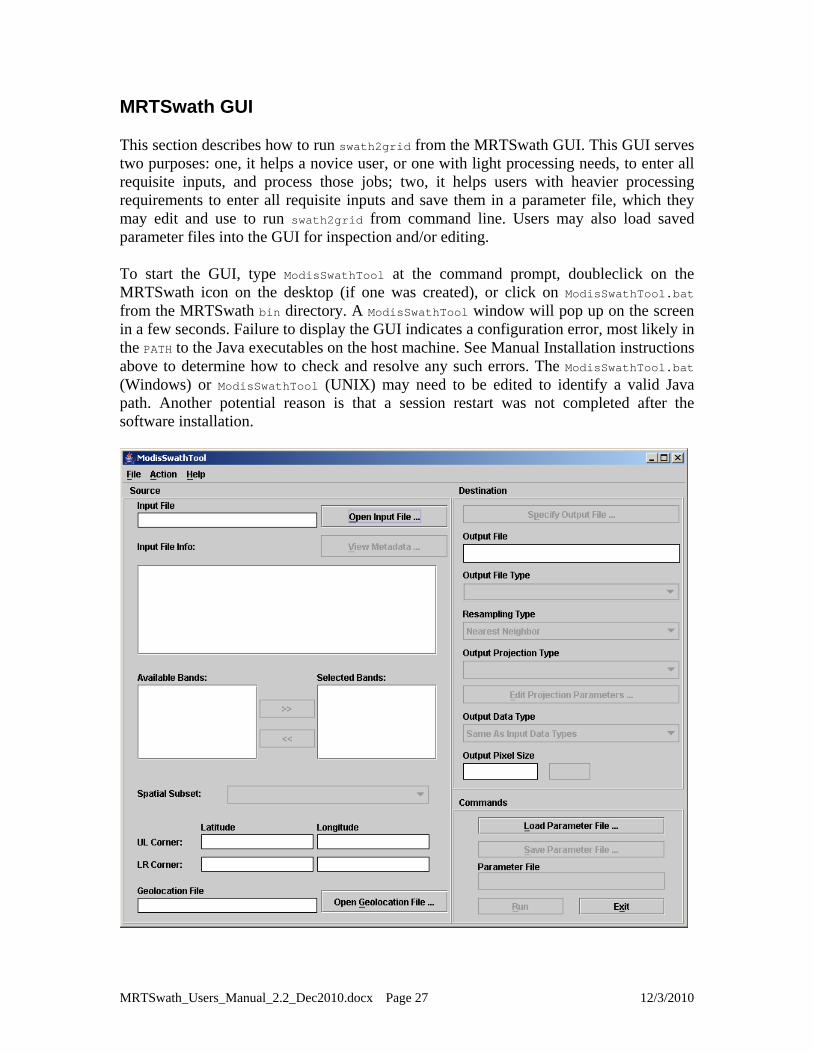
MRTSwath GUI This section describes how to run swath2grid from the MRTSwath GUI. This GUI serves two purposes: one, it helps a novice user, or one with light processing needs, to enter all requisite inputs, and process those jobs; two, it helps users with heavier processing requirements to enter all requisite inputs and save them in a parameter file, which they may edit and use to run swath2grid from command line. Users may also load saved parameter files into the GUI for inspection and/or editing. To start the GUI, type ModisSwathTool at the command prompt, doubleclick on the MRTSwath icon on the desktop (if one was created), or click on ModisSwathTool.bat from the MRTSwath bin directory. A ModisSwathTool window will pop up on the screen in a few seconds. Failure to display the GUI indicates a configuration error, most likely in the PATH to the Java executables on the host machine. See Manual Installation instructions above to determine how to check and resolve any such errors. The ModisSwathTool.bat (Windows) or ModisSwathTool (UNIX) may need to be edited to identify a valid Java path. Another potential reason is that a session restart was not completed after the software installation.
MRTSwath_Users_Manual_2.2_Dec2010.docx Page 27 12/3/2010

To run swath2grid from the GUI, users need to fill in the various fields and click Run. In general, complete fields in the order listed, working down the left (Source) side and progressing down the right (Destination) side. For example, spectral and spatial subsetting parameters may not be selected until an input file is opened, output projection parameters may not be entered until an output projection type is specified, etc. The contents of any field may be changed at any time prior to running swath2grid. Simply click on the field and make the desired changes. Along the top left banner on the GUI is a menu bar labeled with File, Action, and Help. The File menu includes options for opening an input file, a geolocation file, or a parameter file. Other options for specifying an output file and saving a parameter file become active after source information (the fields on the left side of the pane) and destination information (right side) have been entered respectively. These File options mirror the button functions on the GUI. The Action menu includes only the Run function, and is simply an alternative to clicking the Run button to execute swath2grid. The Help menu contains “About” information, and will open a popup displaying the version and date of release of the installed MRTSwath. MRTSwath GUI functionality is described below in the form of sample processing jobs. Two examples are given, one for a two-dimensional swath product, and a second for a multi-dimensional product. For example, a user wishes to subset and project Land Surface Temperature and Quality information in a MOD11_L2 and output the results to GeoTIFF. Obtaining Geolocation Files The swath2grid application needs an associated Geolocation file for any MODIS swath input. The Geolocation files are available through the Level 1 and Atmosphere Archive and Distribution System (LAADS)12 as MOD03, for Terra, and MYD03, for Aqua, products. It is imperative that the Geolocation file from the same acquisition as the input file is used. The standard MODIS file naming convention indicates the acquisition date and time for any product, and provides the information needed to match a Geolocation file to its swath data.
ShortName.AcquisitionYYYYDDD.AcquisitionTime.Version.ProductionYYYYDDDHHMMSS.format
where ShortName is the product measurement, AcquisitionJulianDay is the year and Julian day of acquisition, AcquisitionTime is the five-minute time interval during which the data were acquired,
12 MODIS Geolocation data files are available from the Level 1 and Atmosphere Archive and Distribution System (LAADS) http://ladsweb.nascom.nasa.gov/.
MRTSwath_Users_Manual_2.2_Dec2010.docx Page 28 12/3/2010

Version is the MODIS collection version, ProductionYYYYDDDHHMMSS is the year, Julian day, and time the file was produced, and Format is the file format used to deliver these data. For example, MOD11_L2.A2010244.1530.005.2010245081730.hdf is Land Surface Temperature acquired in 2010 on Julian Day 244 (September 1) at UTC 1530. It is Version 5 data produced in 2010 on Julian day 245 (September 2) at 08:17:30 and is in HDF-EOS format. The second and third fields in the HDF-EOS file name are of interest for matching the MOD11_L2 used as an example to its Geolocation file. When searching for the matching Geolocation file on the LAADS Data Search page, select Terra MODIS, Terra Level 1 Products, MOD03 Geolocation 1km, then enter 09/01/2010 15:30:00 for the Start Date and Time and 09/01/2010 15:30:59 for the End Date and Time. Click Search, then download the resulting MOD03, the name of which will match the second and third fields of the MOD11_L2 name (A2010244.1530). MRTSwath will use the Geolocation file to accurately place the swath data on a chosen mapping grid. Opening an Input File Start on the left pane of the GUI, where source information is entered. Click Open Input File to the right of the Input File field. This will pop up an input file selection dialog box, allowing selection of the desired input file by pointing and left-clicking with the mouse. The default directory is set to the MRTSwath bin, so users need to navigate to the directory containing the input files using the browse tools in the dialog box. These include a drop-down directory tree search, a button to move up one directory, a button to return to the user’s home directory, a button to create a new directory, and options to list or show details of the files in the open directory.
MRTSwath_Users_Manual_2.2_Dec2010.docx Page 29 12/3/2010

An input file is selected either by typing its name into the File Name field at the bottom of the dialog box, by double-clicking on the file name in the directory list, or by highlighting the file name with a single click and pressing Open. When an input file is opened, source information is loaded into the GUI. The file name will appear in the Input File field, basic metadata will be displayed in the Input File Info window, the Selected Bands window will list the science data sets (bands) available in the input file, and the corner coordinates are shown in the Latitude and Longitude fields.
Metadata Examination The basic metadata displayed in the Input File Info window includes the total number of bands, the data type of each band, the number of lines and samples in each band, and the corner coordinates of the swath. Users may examine detailed metadata by clicking on View Metadata above the Input File Info window. This will pop up the internal metadata from the input HDF-EOS swath, including its inventory metadata, archive metadata, and its swath structure.
MRTSwath_Users_Manual_2.2_Dec2010.docx Page 30 12/3/2010
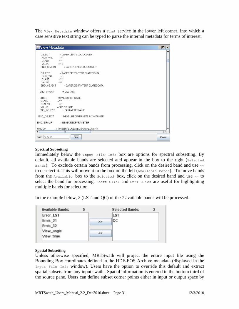
The View Metadata window offers a Find service in the lower left corner, into which a case sensitive text string can be typed to parse the internal metadata for terms of interest.
Spectral Subsetting Immediately below the Input File Info box are options for spectral subsetting. By default, all available bands are selected and appear in the box to the right (Selected Bands). To exclude certain bands from processing, click on the desired band and use << to deselect it. This will move it to the box on the left (Available Bands). To move bands from the Available box to the Selected box, click on the desired band and use >> to select the band for processing. Shift-Click and Ctrl-Click are useful for highlighting multiple bands for selection. In the example below, 2 (LST and QC) of the 7 available bands will be processed.
Spatial Subsetting Unless otherwise specified, MRTSwath will project the entire input file using the Bounding Box coordinates defined in the HDF-EOS Archive metadata (displayed in the Input File Info window). Users have the option to override this default and extract spatial subsets from any input swath. Spatial information is entered in the bottom third of the source pane. Users can define subset corner points either in input or output space by
MRTSwath_Users_Manual_2.2_Dec2010.docx Page 31 12/3/2010

selecting Input Lat/Long, Input Line/Sample, or Output Projection X/Y from the Spatial Subset drop-down.
The UL Corner and LR Corner are populated with the swath bounding coordinates by default. These fields can be edited to specify an area of interest by simply clicking in the box and entering the bounds of the desired subset. If the Spatial Subset type is set to Input Lat/Long, enter corner points in decimal degrees. To subset using Input Line/Sample, specify line/sample pairs using a zero-based coordinate system assuming the upper left corner is (0,0). MRTSwath will use Input Lat/Long or Input Line/Sample to automatically compute the other two rectangle corners (upper right and lower left) in input space. All four corner points will be projected into output space, using the map projection specified later on the destination side of the GUI. A minimum-bounding rectangle is computed in output space that contains the four projected points. All points inside this rectangle in output space are mapped back into input space for projection. When creating a subset based on Output Projection X/Y, these coordinates must be specified in the same units used for the projection (i.e., decimal degrees for Geographic and meters for all other projections). The upper right and lower left corners will be computed from the specified UL Corner and LR Corner to create a rectangle in output space defined by the map projection specified later. These output corners are mapped back to input space to determine their location in input space. The final product after processing should have the same image corner coordinates as specified by the user, but note that MRTSwath will adjust the lower right corner based on output pixel size if its location does not fall in an integral number of lines and samples. Opening a Geolocation File To specify the Geolocation file MRTSwath should use for processing, click the Open Geolocation File button at the bottom of the left pane on the GUI. This opens a dialog box similar to that used for selecting the input files, with the same browse capabilities so users can locate and select the associated Geolocation files.
MRTSwath_Users_Manual_2.2_Dec2010.docx Page 32 12/3/2010

Specify Output File After entering all the necessary source information, the next step is to define the Destination parameters. The first is the name of the output file, which is user-defined through a dialog box invoked by clicking the Specify Output File button on the top of the right pane on the GUI. Similar to the dialog for opening files, output file naming is done by navigating to a preferred directory, then selecting an existing file, or by typing in a new output file name, as shown below.
MRTSwath will expect a file extension appended to the file name, and will not accept a name without it. The file extension indicates the file format of the output image. Adding .hdf will tell MRTSwath to output to HDF-EOS, .tif to output to GeoTIFF, and .hdr to output to raw binary.
MRTSwath_Users_Manual_2.2_Dec2010.docx Page 33 12/3/2010

If an existing file is selected without modifying the file name, an overwrite warning will pop up. The output file format also determines how many files will be delivered at the end of processing. HDF-EOS output consists of one file, and however many bands were processed are packed as science data sets within the file. GeoTIFF and raw binary formats store one band per file, so each band selected for processing results in an output file. The user does not need to specify a new output GeoTIFF name for each selected band, as the band name is automatically appended to the base output file name. For example, having processed the LST and QC bands from a MOD11_L2 swath, HDF-EOS output would consist of a single MOD11_L2.A2010002.1000.hdf, while in GeoTIFF the same output would be delivered as MOD11_L2. A2010002.1000.LST.tif and MOD11_L2.A2010002.1000.QC.tif Output File Type This option is placed under the Specify Output File button, and can be used after a file name is selected to change its format without having to relocate and rename it. Select GeoTIFF, HDFEOS, or RAWBINARY from the Output File Type drop-down list to automatically change the extension of the file name entered in the Output File field. Resampling Type MRTSwath offers three resampling methods from the Resampling Type drop-down list (nearest neighbor, bilinear, or cubic convolution). Note that when projecting thematic data sets, such as the fire mask or any QC band, nearest neighbor is required to avoid mixing categorical values. For example, if 1 = snow, 2 = water, and 3 = fire, resampling methods using averaging will potentially mix 1 and 3 and output a 2.
MRTSwath_Users_Manual_2.2_Dec2010.docx Page 34 12/3/2010

Output Projection Type n Type (Geographic, UTM, etc.) is selected from a drop-down list, The Output Projectio
and its parameters are entered using the Edit Projection Parameters button.
licking the Edit Projection Parameters button will pop up a dialog box in which users Cmay enter or edit up to 15 gridding parameters. Note that the default values appearing in the pop up box are not automatically overwritten when their fields are clicked. Users must delete or highlight them for replacement. Integer values are automatically be converted to floating point. Some parameter fields will be grayed out (uneditable) when they are not used for a particular output projection. These fields are based on the table of projection parameters in Appendix C.
MRTSwath_Users_Manual_2.2_Dec2010.docx Page 35 12/3/2010
The output ellipsoid defaults to WGS-1984, but users may specify alternatives. Either the ellipsoid or the first two projection parameters may be entered, but not both. A special note for Lambert Conformal Conic projections: Although the standard parallels and latitude of origin fields are both open for editing, enter a value into only one or the other. Setting standard parallels effectively does the job of the latitude of origin in LAMCC projection, and having the OriginLat specified as well as the STDPR1 and STDPR2 will place the projected output at inaccurate latitude/longitude coordinates. A special note for UTM projections: MRTSwath differs from MRT in that it does not automatically set the UTM zone. MRTSwath users must specify the appropriate zone when using UTM as an output projection, or the resulting file will likely be ‘empty’ as MRTSwath will not have known where to place the output data pixels. Output Data Type Users have the option to select alternative data types for the output files. Under Edit Projection Parameters is a drop-down selection for Output Data Type. The Same As Input Data Types option is the default, and results in using whatever data type was native to the input band to write the output. For example, checking the basic metadata in the Input File Info window will show what the data type is for each available band in the input HDF-EOS file. In the case of MOD11_L2, there are unsigned 16-bit integer (UINT16) bands and unsigned 8-bit integer (UINT8) bands. By accepting the MRTSwath Output Data Type default, all UINT16 bands would output to UINT16, and all UNIT8 would likewise be output as UINT8. If another Output Data Type option is selected (CHAR8, INT8, UINT8, INT16, or UINT16), all bands will be output to that selection. A data type specification cannot be applied to only one of multiple bands selected for processing. Output Pixel Size Similarly, an Output Pixel Size may be specified (in decimal degrees for the Geographic projection, meters for all other projections). For reference, 250-m is 0.00225 degrees, 500-m is 0.0045 degrees, and 1,000-m is 0.009 degrees. If left blank, the output pixel size remains the same as the corresponding input pixel size for each selected band. If specified, the output pixel size will be used for all selected bands. This helps normalize MODIS swath outputs which, due to their basis in arcseconds, are actually 926.6-m pixels instead of 1,000-m. The MRTSwath Output Pixel Size function is not recommended as a tool to rescale 1,000-m data to higher resolutions. Load or Save Parameter File The MRTSwath offers a method to retain all the destination and source parameters just entered through the steps above. This is useful if there is more than one file to process to the same specifications, if users need to use the same parameters at a later session, or if
MRTSwath_Users_Manual_2.2_Dec2010.docx Page 36 12/3/2010
users do not want to enter all the parameter information repeatedly. To save all information just entered on the GUI, click on Save Parameter File and type in a file name. Unlike specifying an image output file, it is not necessary to include a file extension with the name and a file with the extension .prm is created in the directory of choice (see the sample parameter file included in the Batch Processing section). An existing file name may be used, but the file will be overwritten unless it is modified. The parameters from the last MRTSwath session are retrievable from the MRTSwath bin directory, where the most recently executed parameters are saved in TmpParam.prm. To restore saved parameters, simply click Load Parameter File, navigate to the desired .prm and click Open. This will restore all the parameters in the source and destination fields on the GUI. The fields can be edited any time prior to clicking Run. The saved .prm can also be used to feed command line processing (see Batch Processing section). Executing swath2grid
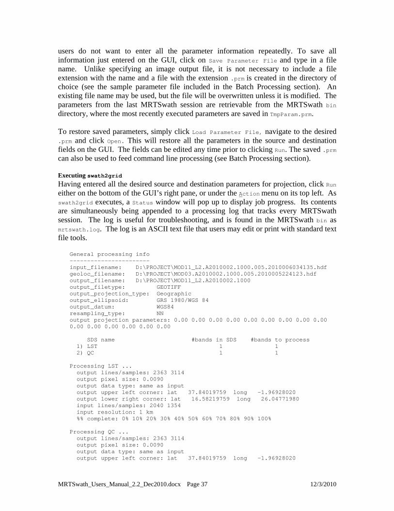
Having entered all the desired source and destination parameters for projection, click Run
either on the bottom of the GUI’s right pane, or under the Action menu on its top left. As swath2grid executes, a Status window will pop up to display job progress. Its contents are simultaneously being appended to a processing log that tracks every MRTSwath session. The log is useful for troubleshooting, and is found in the MRTSwath bin as mrtswath.log. The log is an ASCII text file that users may edit or print with standard text file tools.
General processing info ----------------------- input_filename: D:\PROJECT\MOD11_L2.A2010002.1000.005.2010006034135.hdf geoloc_filename: D:\PROJECT\MOD03.A2010002.1000.005.2010005224123.hdf output_filename: D:\PROJECT\MOD11_L2.A2010002.1000 output_filetype: GEOTIFF output_projection_type: Geographic output_ellipsoid: GRS 1980/WGS 84 output_datum: WGS84 resampling_type: NN output projection parameters: 0.00 0.00 0.00 0.00 0.00 0.00 0.00 0.00 0.00 0.00 0.00 0.00 0.00 0.00 0.00 SDS name #bands in SDS #bands to process 1) LST 1 1 2) QC 1 1 Processing LST ... output lines/samples: 2363 3114 output pixel size: 0.0090 output data type: same as input output upper left corner: lat 37.84019759 long -1.96928020 output lower right corner: lat 16.58219759 long 26.04771980 input lines/samples: 2040 1354 input resolution: 1 km %% complete: 0% 10% 20% 30% 40% 50% 60% 70% 80% 90% 100% Processing QC ... output lines/samples: 2363 3114 output pixel size: 0.0090 output data type: same as input output upper left corner: lat 37.84019759 long -1.96928020
MRTSwath_Users_Manual_2.2_Dec2010.docx Page 37 12/3/2010

output lower right corner: lat 16.58219759 long 26.04771980 input lines/samples: 2040 1354 input resolution: 1 km %% complete: 0% 10% 20% 30% 40% 50% 60% 70% 80% 90% 100% End Time: Wed Oct 27 14:46:10 2010 Finished processing! ****************************************************************************
When users click the Run button, the GUI creates a temporary parameter file (TmpParam.prm) in the bin directory and runs swath2grid using that parameter file (swath2grid –pf=TmpParam.prm). This file is overwritten on subsequent runs, but not deleted, so it can be examined with any ASCII text file viewer/editor when processing is complete. Exiting MRTSwath To exit the ModisSwathTool GUI, click the Exit button or click File then Exit on the menu bar. Standard operating system commands can also be used (e.g., double click on the Close button, or the X in the upper right hand corner of the window).
MRTSwath_Users_Manual_2.2_Dec2010.docx Page 38 12/3/2010

Contacts MRTSwath is available from the LP DAAC at the USGS Earth Resources Observation and Science (EROS) Center. Please direct all bug reports, other comments, and requests for download and installation assistance to the following:
NASA Land Processes Distributed Active Archive Center User Services USGS Earth Resources Observation and Science (EROS) 47914 252nd Street Sioux Falls, SD 57198-0001 Voice: 605-594-6116 Toll Free: 866-573-3222 Fax: 605-594-6963 E-mail: [email protected] Web: https://LPDAAC.usgs.gov
MRTSwath_Users_Manual_2.2_Dec2010.docx Page 39 12/3/2010
Appendix A: MRTSwath Parameter File Format The MRTSwath requires information about the input and output data products in order to perform the desired data transformations. The parameter file contains this information in user-editable ASCII text format. For the most part, this information is stored as field-value pairs. File naming conventions
By convention, all related files in a data set should be given the same base filename. Different extensions indicate the file type: parameter files (.prm), raw binary header files (.hdr), raw binary data files (.dat), HDF-EOS files (.hdf), and GeoTIFF files (.tif). Parameter file format
The parameter file13 consists of field-value pairs and comments. Comments begin with the # character at the beginning of the line, and extend to the end of the line. Each field must begin on a new line, and may span more than one line for convenience and readability. Fields may occur in any order. To verify the format of any of the fields below, enter the desired information using the GUI, then use the Save Parameter File button to generate a sample file that can be examined for content. INPUT_FILENAME = <input file name> (abbrev. IF) The input data file name is a required field that provides requisite processing information. Only MODIS swath HDF-EOS file names are accepted. The file name may contain a directory path. An invalid file name or non-swath product will generate an error. UNIX users are advised to enclose file names in “double quotes.” OUTPUT_FILENAME = <output file name> (abbrev. OF) The output file name is required. A file extension is not needed when entered in a parameter file (unlike when entered in the GUI). Including a directory path in the OUTPUT_FILENAME is optional. If an output file extension of .hdf, .HDF, .tif, .TIF, .hdr, or .HDR is specified, it will be ignored, because the file format is determined from the OUTPUT_FILE_FORMAT field in the parameter file. UNIX users are advised to enclose file names in “double quotes.” OUTPUT_FILE_FORMAT = <output file format> (abbrev. OFF) The output file format specifies the format of the output file. Valid values are HDF_FMT, GEOTIFF_FMT, RB_FMT. This field is optional, and if not specified, the default is HDF_FMT. GEOLOCATION_FILENAME = <name of geolocation file> (abbrev. GF) This field is required, since much of the information required by the MRTSwath must be read from the geolocation file associated with the input swath. The MOD03/MYD03 is a
13 Look in the MRTSwath bin directory for sample parameter files.
MRTSwath_Users_Manual_2.2_Dec2010.docx Page 40 12/3/2010
LAADS14 product that is defines the geolocation of a MODIS swath. It must have the same date/time as the input MODIS L1 or L2 swath product specified in INPUT_FILENAME (see Obtaining Geolocation Files above). The geolocation file name may optionally contain a directory path. An invalid file name will generate an error. UNIX users are advised to enclose file names in “double quotes.” INPUT_SDS_NAME = <input SDS name> (abbrev. SDS) The spectral subsetting can be specified using this parameter. This field is optional, and if not specified, the default is to process all bands in the HDF-EOS input file (Science Data Sets, SDS). Some MODIS swath products contain bands that do not match the nominal MODIS scan size (2030x1354). For these bands, the MRTSwath will output an error message but continue processing any remaining bands. The syntax of the INPUT_SDS_NAME field will define selections for multi-dimensional input files. For example, the MOD35_L2 MODIS Terra Cloud Mask includes 9 bands, one of which is called MODIS Cloud Mask and Spectral Test Results. Inside this band are 6 byte words describing various cloud conditions and test results. In order to process only the first and second byte words with MRTSwath (to determine general cloud state and cloud type), the INPUT_SDS_NAME is entered as follows.
INPUT_SDS_NAME=Cloud_Mask,1,1,0,0,0,0 where 1 indicates which bytes to process and 0 which bytes to ignore. KERNEL_TYPE = <kernel type> (abbrev. KK) The resampling kernel type options are nearest neighbor (NN), bilinear (BI), or cubic convolution (CC). This field is optional. By default, nearest neighbor resampling is used for processing. OUTPUT_PROJECTION_NUMBER = <output projection number or short name> (abbrev. OPROJ) The output projection type may be one of the following.
Albers Equal Area (AEA) Equirectangular (ER) Geographic (GEO) Interrupted Goode Homolosine (GOODE) Hammer (HAM) Integerized Sinusoidal (ISIN) Lambert Azimuthal (LAMAZ) Lambert Conformal Conic (LAMCC) Mercator (MERCAT) Mollweide (MOLL) Polar Stereographic (PS) Sinusoidal (SNSOID)
14 MODIS Geolocation data files are available from the Level 1 and Atmosphere Archive and Distribution System (LAADS) http://ladsweb.nascom.nasa.gov/.
MRTSwath_Users_Manual_2.2_Dec2010.docx Page 41 12/3/2010
Transverse Mercator (TM) Universal Transverse Mercator (UTM)
OUTPUT_PROJECTION_PARAMETER = <output projection parameters> (abbrev. OPRM) This array contains the 15 output projection parameter values15. This field is optional. By default, all projection parameter values are set to zero. Projection parameter values are floating point; integer values are automatically converted to floating point. If there are fewer than 15 projection parameter values specified the remaining values are set to zero. Coordinate values (latitudes and longitudes) should be entered in decimal degrees OUTPUT_PIXEL_SIZE = <output pixel sizes> (abbrev. OPSZ) The output pixel size may be specified for each band processed, in output projection units (meters for all projections except Geographic which requires units of decimal degrees). For example, if five bands are selected for processing, and the user wishes for some reason to output one of the bands at a different resolution, the line in the parameter file would look like this below.
OUTPUT_PIXEL_SIZE = 1000,1200,1000,1000,1000
Otherwise, the default is to output to the same resolution as the input for each band, which is generally the same for each band. This field is optional, but given the native pixel resolution of MODIS swath data, users may utilize it to normalize the output pixels (e.g., change 926.6-m input to 1,000-m output). If the number of output pixel sizes entered in this field is less than the number of bands processed, then the last pixel size entered is used as the pixel size all bands. For example, it is not necessary to write out the output resolution for all bands if the same output resolution is desired for all bands. Simply entering the following will apply the desired output pixel size to all bands selected for processing.
OUTPUT_PIXEL_SIZE = 1000
OUTPUT_SPATIAL_SUBSET_TYPE = <output spatial subset type> (abbrev. OSST) Spatial subsets may be defined using input latitude and longitude coordinates (LAT_LONG), input lines and samples (LINE_SAMPLE), or output projection X and Y coordinates (PROJ_COORDS). This field is optional and the default is LAT_LONG. OUTPUT_SPACE_UPPER_LEFT_CORNER = <output upper left corner> (abbrev. OUL) OUTPUT_SPACE_LOWER_RIGHT_CORNER = <output lower right corner> (abbrev. OLR) These are the coordinates of the upper-left and lower-right corners for spatial subsetting, defined in units appropriate to the selected OUTPUT_SPATIAL_SUBSET_TYPE. These fields are optional. By default, the entire input image will be selected. The bounding rectangular coordinates in the input file’s metadata are used to determine the image coordinates.
15 See Appendix C for more information on projection parameters. Or type swath2grid –help=<projection> at the command line.
MRTSwath_Users_Manual_2.2_Dec2010.docx Page 42 12/3/2010

The parameter field is formatted as follows for each subset type.
OUTPUT_SPACE_UPPER_LEFT_CORNER (LONG LAT) = -1.969280203 37.840197592 OUTPUT_SPACE_LOWER_RIGHT_CORNER (LONG LAT) = 26.054383372 16.574757586 OUTPUT_SPACE_UPPER_LEFT_CORNER (SAMPLE LINE) = 20 20 OUTPUT_SPACE_LOWER_RIGHT_CORNER (SAMPLE LINE) = 1353 2029 OUTPUT_SPACE_UPPER_LEFT_CORNER (X Y) = 635521.0 1235874.0 OUTPUT_SPACE_LOWER_RIGHT_CORNER (X Y) = 137256.0 82544.0
If specifying a subset based on the input coordinates, be sure to use decimal degrees for Geographic and meters for all other projections. In the case of multi-resolution data sets, the highest resolution of any spectral band is assumed for line/sample values. OUTPUT_PROJECTION_SPHERE = <output projection sphere> (abbrev. OSP) Users may specify an output projection sphere value. Otherwise the first two projection parameter fields are used to specify sphere information. Valid entries for the sphere field include the following GCTP standards.
0 Clarke 1866 1 Clarke 1880 2 Bessel 3 International 1967 4 International 1909 5 WGS 72 6 Everest 7 WGS 66 8 GRS 1980/WGS 84 9 Airy 10 Modified Everest 11 Modified Airy 12 Walbeck 13 Southeast Asia 14 Australian National 15 Krassovsky 16 Hough 17 Mercury 1960 18 Modified Mercury 1968 19 Sphere 19 (Radius 6370997) 20 MODIS Sphere (Radius 6371007.181)16
OUTPUT_PROJECTION_ZONE = <output projection zone> (abbrev. OZN) Users selecting UTM output projection type must enter a UTM zone value. Valid values are –60 to +60. OUTPUT_DATA_TYPE = <output data type> (abbrev. OTY) The valid options for the output data type are CHAR8, UINT8, INT8, INT16, and UINT16. Only one option can be specified, thus all output bands are converted to the specified data type. The default is to use the same output data type as the input data type, even if the input bands have varying data types. This field is optional.
16 For more information on the spheres and their semi-major and semi-minor axes, type swath2grid –help=proj at the command line.
MRTSwath_Users_Manual_2.2_Dec2010.docx Page 43 12/3/2010

Appendix B: MRTSwath Raw Binary File Format This appendix specifies the format of the header file for the MODIS raw binary file format. In this file format, raw binary data and header information are stored in separate files. The header file contains information required by MRTSwath for processing MODIS data in the raw binary file format. Header files consist of user-editable ASCII text in the format described below. Raw binary MODIS data are stored in individual data files, with one band per file. Within each output file, data are stored in row-major order, starting at the upper-left corner of the image. The data type options include character, 8-bit integer, 16-bit integer, or 32-bit integer. Integer values may be signed or unsigned. The output byte order is dependent on the system used for processing the data. File naming conventions
By convention, all related files in raw binary file format are given the same base filename. Header and data filenames are generated from the base name and the band name, and given the .hdr and .dat extensions, as follows: basename.band_name_b#.hdr and basename.band_name_b#.dat. For example:
MOD021KM_EV_500_Aggr1km_RefSB_b0.hdr - header file (band 1) MOD021KM_EV_500_Aggr1km_RefSB_b0.dat - data file (band 1) MOD021KM_EV_500_Aggr1km_RefSB_b4.hdr - header file (band 5) MOD021KM_EV_500_Aggr1km_RefSB_b4.dat - data file (band 5) …..
Header file format
The header file contains information output by the MRTSwath while processing data in the raw binary file format. An ODL-like format is used, as illustrated by the following:
# Header file for MOD021KM.A2003283.1655.004.2003283232504 PROJECTION_TYPE = UTM UTM_ZONE = 13 PROJECTION_PARAMETERS = ( 0.000000000 0.000000000 0.000000000 0.000000000 0.000000000 0.000000000 0.000000000 0.000000000 0.000000000 0.000000000 0.000000000 0.000000000 0.000000000 0.000000000 0.000000000) UL_CORNER_LATLON = ( 61.508496018 -104.390761607 ) UR_CORNER_LATLON = ( 61.508496018 -70.464295568 ) LL_CORNER_LATLON = ( 29.257995161 -104.390761607 ) LR_CORNER_LATLON = ( 29.257995161 -70.464295568 ) UL_CORNER_XY = ( 532422.785853664 6819579.592400375 )
MRTSwath_Users_Manual_2.2_Dec2010.docx Page 44 12/3/2010

UR_CORNER_XY = ( 3947422.785853664 6819579.592400375 ) LL_CORNER_XY = ( 532422.785853664 3788579.592400375 ) LR_CORNER_XY = ( 3947422.785853664 3788579.592400375 ) NBANDS = 1 BANDNAMES = ( EV_1KM_RefSB_b0 ) DATA_TYPE = ( UINT16 ) NLINES = ( 3031 ) NSAMPLES = ( 3415 ) PIXEL_SIZE = ( 1000.000000000000 ) BACKGROUND_FILL = ( 0.000000 ) DATUM = WGS84
Notes
All text following # on a line is considered a comment. Some comment lines are automatically generated by MRTSwath for projection to a raw binary output image, for informational purposes only.
Field names are largely self-explanatory. Lower-case items represent numeric and
string values for the various fields. When dealing with UTM data types, the UTM_ZONE is used to specify the zone. Users
may enter valid UTM_ZONE values between –60 and 60. There are two sets of corner coordinate fields: CORNER_XY coordinates (x/y in
projection units) and CORNER_LATLON coordinates (lat/lon in decimal degrees). Valid DATA_TYPE values are CHAR8, UINT8, INT8, INT16, and UINT16.
MRTSwath_Users_Manual_2.2_Dec2010.docx Page 45 12/3/2010
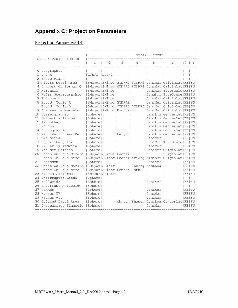
Appendix C: Projection Parameters Projection Parameters 1-8 ----------------------------------------------------------------------------- | Array Element | Code & Projection Id |---------------------------------------------------- | 1 | 2 | 3 | 4 | 5 | 6 |7 | 8| ----------------------------------------------------------------------------- 0 Geographic | | | | | | | | | 1 U T M |Lon/Z |Lat/Z | | | | | | | 2 State Plane | | | | | | | | | 3 Albers Equal Area |SMajor|SMinor|STDPR1|STDPR2|CentMer|OriginLat|FE|FN| 4 Lambert Conformal C |SMajor|SMinor|STDPR1|STDPR2|CentMer|OriginLat|FE|FN| 5 Mercator |SMajor|SMinor| | |CentMer|TrueScale|FE|FN| 6 Polar Stereographic |SMajor|SMinor| | |LongPol|TrueScale|FE|FN| 7 Polyconic |SMajor|SMinor| | |CentMer|OriginLat|FE|FN| 8 Equid. Conic A |SMajor|SMinor|STDPAR| |CentMer|OriginLat|FE|FN| Equid. Conic B |SMajor|SMinor|STDPR1|STDPR2|CentMer|OriginLat|FE|FN| 9 Transverse Mercator |SMajor|SMinor|Factor| |CentMer|OriginLat|FE|FN| 10 Stereographic |Sphere| | | |CentLon|CenterLat|FE|FN| 11 Lambert Azimuthal |Sphere| | | |CentLon|CenterLat|FE|FN| 12 Azimuthal |Sphere| | | |CentLon|CenterLat|FE|FN| 13 Gnomonic |Sphere| | | |CentLon|CenterLat|FE|FN| 14 Orthographic |Sphere| | | |CentLon|CenterLat|FE|FN| 15 Gen. Vert. Near Per |Sphere| |Height| |CentLon|CenterLat|FE|FN| 16 Sinusoidal |Sphere| | | |CentMer| |FE|FN| 17 Equirectangular |Sphere| | | |CentMer|TrueScale|FE|FN| 18 Miller Cylindrical |Sphere| | | |CentMer| |FE|FN| 19 Van der Grinten |Sphere| | | |CentMer|OriginLat|FE|FN| 20 Hotin Oblique Merc A |SMajor|SMinor|Factor| | |OriginLat|FE|FN| Hotin Oblique Merc B |SMajor|SMinor|Factor|AziAng|AzmthPt|OriginLat|FE|FN| 21 Robinson |Sphere| | | |CentMer| |FE|FN| 22 Space Oblique Merc A |SMajor|SMinor| |IncAng|AscLong| |FE|FN| Space Oblique Merc B |SMajor|SMinor|Satnum|Path | | |FE|FN| 23 Alaska Conformal |SMajor|SMinor| | | | |FE|FN| 24 Interrupted Goode |Sphere| | | | | | | | 25 Mollweide |Sphere| | | |CentMer| |FE|FN| 26 Interrupt Mollweide |Sphere| | | | | | | | 27 Hammer |Sphere| | | |CentMer| |FE|FN| 28 Wagner IV |Sphere| | | |CentMer| |FE|FN| 29 Wagner VII |Sphere| | | |CentMer| |FE|FN| 30 Oblated Equal Area |Sphere| |Shapem|Shapen|CentLon|CenterLat|FE|FN| 31 Integerized Sinusoid |Sphere| | | |CentMer| |FE|FN| -----------------------------------------------------------------------------
MRTSwath_Users_Manual_2.2_Dec2010.docx Page 46 12/3/2010

Projection Parameters 9-15 --------------------------------------------------------- | Array Element | Code & Projection Id |--------------------------- | 9 | 10 | 11 | 12 | 13 | --------------------------------------------------------- 0 Geographic | | | | | | 1 U T M | | | | | | 2 State Plane | | | | | | 3 Albers Equal Area | | | | | | 4 Lambert Conformal C | | | | | | 5 Mercator | | | | | | 6 Polar Stereographic | | | | | | 7 Polyconic | | | | | | 8 Equid. Conic A |zero | | | | | Equid. Conic B |one | | | | | 9 Transverse Mercator | | | | | | 10 Stereographic | | | | | | 11 Lambert Azimuthal | | | | | | 12 Azimuthal | | | | | | 13 Gnomonic | | | | | | 14 Orthographic | | | | | | 15 Gen. Vert. Near Per | | | | | | 16 Sinusoidal | | | | | | 17 Equirectangular | | | | | | 18 Miller Cylindrical | | | | | | 19 Van der Grinten | | | | | | 20 Hotin Oblique Merc A |Long1|Lat1|Long2|Lat2|zero| Hotin Oblique Merc B | | | | |one | 21 Robinson | | | | | | 22 Space Oblique Merc A |PSRev|LRat|PFlag| |zero| Space Oblique Merc B | | | | |one | 23 Alaska Conformal | | | | | | 24 Interrupted Goode | | | | | | 25 Mollweide | | | | | | 26 Interrupt Mollweide | | | | | | 27 Hammer | | | | | | 28 Wagner IV | | | | | | 29 Wagner VII | | | | | | 30 Oblated Equal Area |Angle| | | | | 31 Integerized Sinusoidal |NZone| |RFlag| | | ---------------------------------------------------------
MRTSwath_Users_Manual_2.2_Dec2010.docx Page 47 12/3/2010
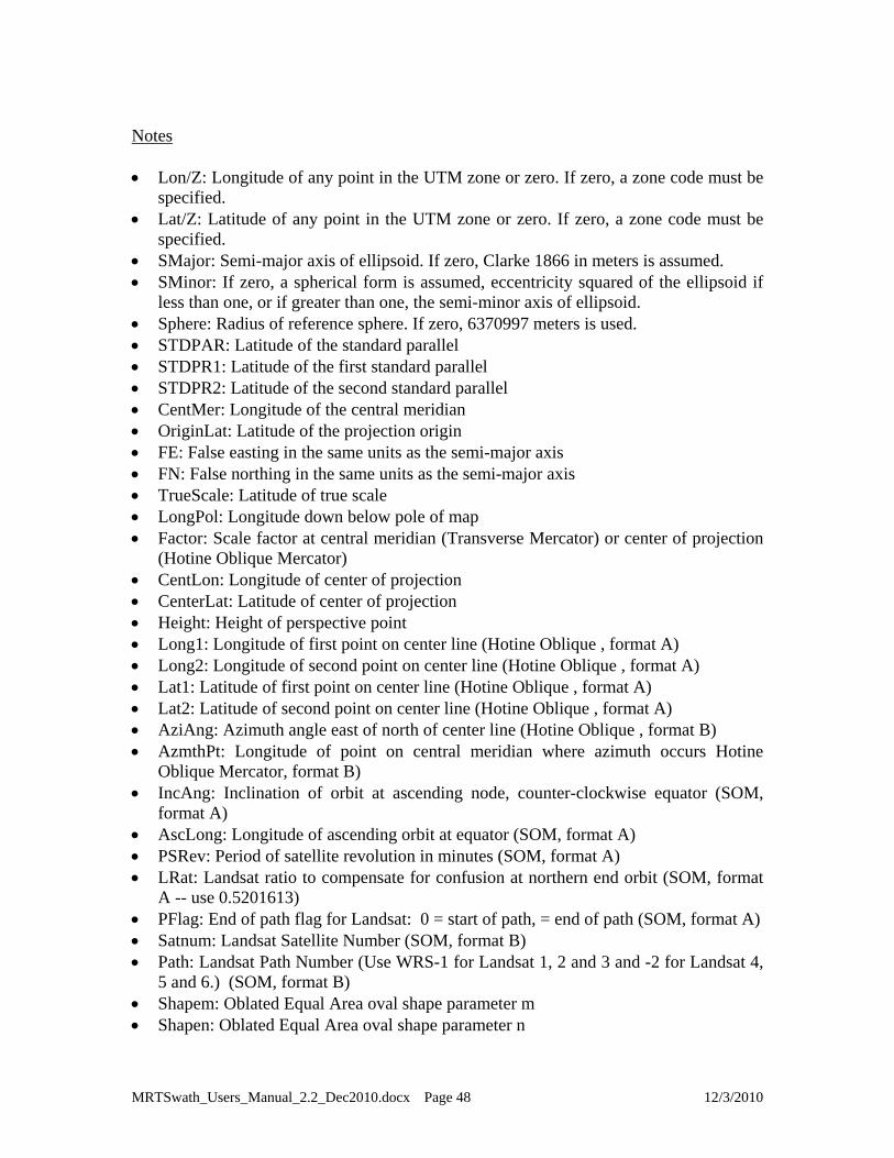
Notes Lon/Z: Longitude of any point in the UTM zone or zero. If zero, a zone code must be
specified. Lat/Z: Latitude of any point in the UTM zone or zero. If zero, a zone code must be
specified. SMajor: Semi-major axis of ellipsoid. If zero, Clarke 1866 in meters is assumed. SMinor: If zero, a spherical form is assumed, eccentricity squared of the ellipsoid if
less than one, or if greater than one, the semi-minor axis of ellipsoid. Sphere: Radius of reference sphere. If zero, 6370997 meters is used. STDPAR: Latitude of the standard parallel STDPR1: Latitude of the first standard parallel STDPR2: Latitude of the second standard parallel CentMer: Longitude of the central meridian OriginLat: Latitude of the projection origin FE: False easting in the same units as the semi-major axis FN: False northing in the same units as the semi-major axis TrueScale: Latitude of true scale LongPol: Longitude down below pole of map Factor: Scale factor at central meridian (Transverse Mercator) or center of projection
(Hotine Oblique Mercator) CentLon: Longitude of center of projection CenterLat: Latitude of center of projection Height: Height of perspective point Long1: Longitude of first point on center line (Hotine Oblique , format A) Long2: Longitude of second point on center line (Hotine Oblique , format A) Lat1: Latitude of first point on center line (Hotine Oblique , format A) Lat2: Latitude of second point on center line (Hotine Oblique , format A) AziAng: Azimuth angle east of north of center line (Hotine Oblique , format B) AzmthPt: Longitude of point on central meridian where azimuth occurs Hotine
Oblique Mercator, format B) IncAng: Inclination of orbit at ascending node, counter-clockwise equator (SOM,
format A) AscLong: Longitude of ascending orbit at equator (SOM, format A) PSRev: Period of satellite revolution in minutes (SOM, format A) LRat: Landsat ratio to compensate for confusion at northern end orbit (SOM, format
A -- use 0.5201613) PFlag: End of path flag for Landsat: 0 = start of path, = end of path (SOM, format A) Satnum: Landsat Satellite Number (SOM, format B) Path: Landsat Path Number (Use WRS-1 for Landsat 1, 2 and 3 and -2 for Landsat 4,
5 and 6.) (SOM, format B) Shapem: Oblated Equal Area oval shape parameter m Shapen: Oblated Equal Area oval shape parameter n
MRTSwath_Users_Manual_2.2_Dec2010.docx Page 48 12/3/2010

MRTSwath_Users_Manual_2.2_Dec2010.docx Page 49 12/3/2010
Angle: Oblated Equal Area oval rotation angle NZone: Number of equally spaced latitudinal zones (rows); must be 2 or larger and
even RFlag: Right justify columns flag is used to indicate what to do with zones with an
odd number of columns. If it has a value of 0 or 1 it indicates the extra column is on the right (zero) or left (one) of the projection y-axis. If the flag is set to 2 the number of columns are calculated so there are always an even number of column in each zone.
Array elements 14 and 15 are set to zero All array elements with blank fields are set to zero All angles (latitudes, longitudes, azimuths, etc.) are entered in decimal degrees and
the MRTSwath then converts them to packed degrees/minutes/seconds (DDDMMMSSS.SS) format for the call to GCTP.


