UP Series - Solar Hot Water - FREE Hot Water - Solene...
92
GRUNDFOS DATA BOOKLET UP Series Circulator pumps 60 Hz
Transcript of UP Series - Solar Hot Water - FREE Hot Water - Solene...
GRUNDFOS DATA BOOKLET
UP SeriesCirculator pumps60 Hz
Ta
ble
of c
on
ten
ts
2
UP Series
1. Cross reference charts 3Quick cross reference for competitive 3-speed pumps 3Quick cross reference for competitive models 4Reference for replacing TACO models 5Reference for replacing Bell & Gossett models 14Reference for replacing Laing models 17Reference for replacing Armstrong models 19Reference for replacing Wilo models 22Discontinued products 24
2. Performance ranges 253-speed 253-speed, stainless steel 26UP 10-16 A/PM B5/BN5/BU 26Closed systems 27Open systems 27Open systems, 1/2" 28Open systems, 3/4" 28
3. Product range 29Cast iron 29Bronze 30Stainless steel 31
4. Identification 32Type key 32Nameplate 33
5. Applications 34Heating systems 34Domestic hot-water systems 34Cooling systems 34Construction 34Materials of construction 35Installation 35Pumped liquids 36Ambient and liquid temperatures 36Maximum system pressure 36Minimum inlet pressure 36Performance 36ALPHA 37MixiMizer™ - mixing reset pump 38Variable-speed pump 39Comfort System 40UP 10-16 Comfort PM, PM Auto 41
6. Technical data 42UP 10-16 Comfort PM, PM Auto 42UP 15-10 B5/B7 43UP 15-10 BUC5/BUC7 44UP 15-10 F/FR 45UP Comfort system 46UP 15-18 B5/B7 47UP 15-18 BUC5/BUC7 48UP 15-29 SU/SF 49UP 15-35 SUC 50UPS 15-35 SUC/SFC 51UP 15-42 B5/B7 52UP 15-42 BUC5/BUC7 53UP 15 MixiMizer™ 54UP 15-42 F/FR 55UPS 15-42 F 56UP 15 MixiMizer™ 57UP variable speed 58UP 15-55 SUC 59UPS 15-55 SFC/SUC/TLC 60UP 15 ALPHA 61UP 15 ALPHA 62UPS 15-58 FC/FRC 63UP 15-100 F 64UP 26-64 F 65UP 26 variable speed 66UP 26-96 F/BF 67UP 26 variable speed 68UP 26-99 F/BF 69UPS 26-99 FC/BFC 70UP 26-116 F/BF 71UP 26-120 U 72UPS 26-150 F/SF 73UP 43-44 F/BF 74UPS 43-44 FC/BFC 75UP 43-70 F 76UP 43-75 F/BF 77UPS 43-100 F/SF 78UP 43-110 F 79UPS 50-44 F 80UPS 50-60 F/SF 81UP 50-75 F 82
7. Accessories 83UP timer 83Aquastat 84Packaged dielectric isolating valve sets 85Packaged fitting sets 86UP-ZV zone valves 87Technical data 87Replacement flange gaskets 89
8. Further product information 90WebCAPS 90WinCAPS 91Grundfos GO 92
Cro
ss
re
fere
nc
e c
ha
rts
UP Series 1
3
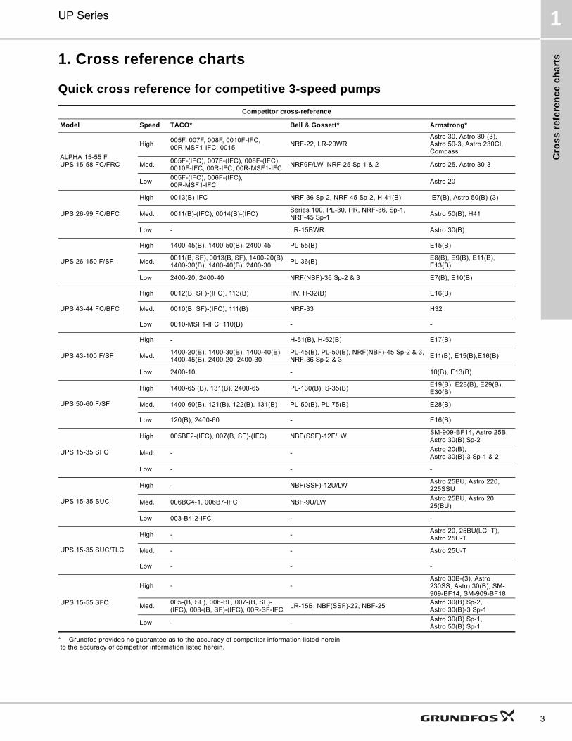
1. Cross reference charts
Quick cross reference for competitive 3-speed pumps
* Grundfos provides no guarantee as to the accuracy of competitor information listed herein. to the accuracy of competitor information listed herein.
Competitor cross-reference
Model Speed TACO* Bell & Gossett* Armstrong*
ALPHA 15-55 FUPS 15-58 FC/FRC
High005F, 007F, 008F, 0010F-IFC,00R-MSF1-IFC, 0015
NRF-22, LR-20WRAstro 30, Astro 30-(3), Astro 50-3, Astro 230CI, Compass
Med.005F-(IFC), 007F-(IFC), 008F-(IFC), 0010F-IFC, 00R-IFC, 00R-MSF1-IFC
NRF9F/LW, NRF-25 Sp-1 & 2 Astro 25, Astro 30-3
Low005F-(IFC), 006F-(IFC),00R-MSF1-IFC
Astro 20
UPS 26-99 FC/BFC
High 0013(B)-IFC NRF-36 Sp-2, NRF-45 Sp-2, H-41(B) E7(B), Astro 50(B)-(3)
Med. 0011(B)-(IFC), 0014(B)-(IFC)Series 100, PL-30, PR, NRF-36, Sp-1, NRF-45 Sp-1
Astro 50(B), H41
Low - LR-15BWR Astro 30(B)
UPS 26-150 F/SF
High 1400-45(B), 1400-50(B), 2400-45 PL-55(B) E15(B)
Med.0011(B, SF), 0013(B, SF), 1400-20(B), 1400-30(B), 1400-40(B), 2400-30
PL-36(B)E8(B), E9(B), E11(B), E13(B)
Low 2400-20, 2400-40 NRF(NBF)-36 Sp-2 & 3 E7(B), E10(B)
UPS 43-44 FC/BFC
High 0012(B, SF)-(IFC), 113(B) HV, H-32(B) E16(B)
Med. 0010(B, SF)-(IFC), 111(B) NRF-33 H32
Low 0010-MSF1-IFC, 110(B) - -
UPS 43-100 F/SF
High - H-51(B), H-52(B) E17(B)
Med.1400-20(B), 1400-30(B), 1400-40(B), 1400-45(B), 2400-20, 2400-30
PL-45(B), PL-50(B), NRF(NBF)-45 Sp-2 & 3, NRF-36 Sp-2 & 3
E11(B), E15(B),E16(B)
Low 2400-10 - 10(B), E13(B)
UPS 50-60 F/SF
High 1400-65 (B), 131(B), 2400-65 PL-130(B), S-35(B)E19(B), E28(B), E29(B), E30(B)
Med. 1400-60(B), 121(B), 122(B), 131(B) PL-50(B), PL-75(B) E28(B)
Low 120(B), 2400-60 - E16(B)
UPS 15-35 SFC
High 005BF2-(IFC), 007(B, SF)-(IFC) NBF(SSF)-12F/LWSM-909-BF14, Astro 25B, Astro 30(B) Sp-2
Med. - -Astro 20(B), Astro 30(B)-3 Sp-1 & 2
Low - - -
UPS 15-35 SUC
High - NBF(SSF)-12U/LWAstro 25BU, Astro 220, 225SSU
Med. 006BC4-1, 006B7-IFC NBF-9U/LWAstro 25BU, Astro 20, 25(BU)
Low 003-B4-2-IFC - -
UPS 15-35 SUC/TLC
High - -Astro 20, 25BU(LC, T),Astro 25U-T
Med. - - Astro 25U-T
Low - - -
UPS 15-55 SFC
High - -Astro 30B-(3), Astro 230SS, Astro 30(B), SM-909-BF14, SM-909-BF18
Med.005-(B, SF), 006-BF, 007-(B, SF)-(IFC), 008-(B, SF)-(IFC), 00R-SF-IFC
LR-15B, NBF(SSF)-22, NBF-25Astro 30(B) Sp-2,Astro 30(B)-3 Sp-1
Low - -Astro 30(B) Sp-1,Astro 50(B) Sp-1
Cro
ss
refe
ren
ce
ch
arts
UP Series1
4
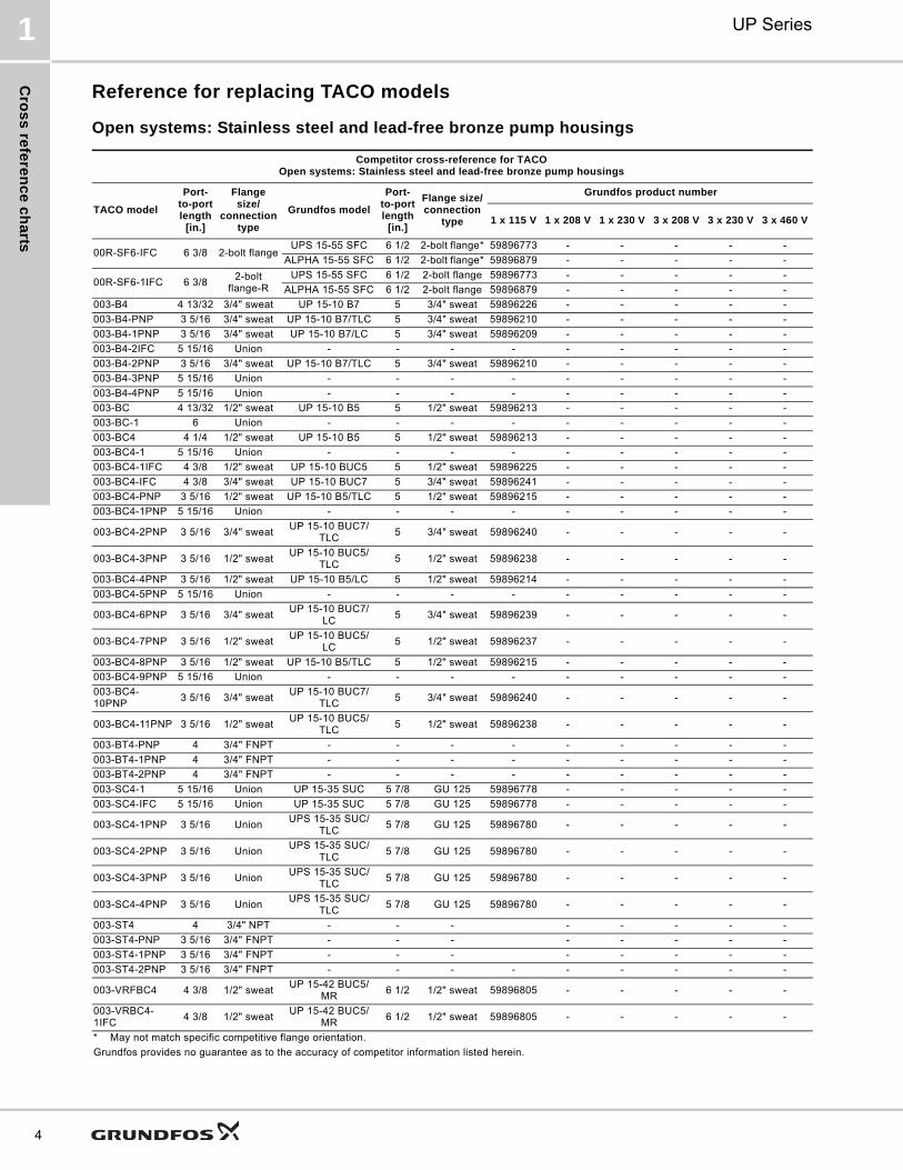
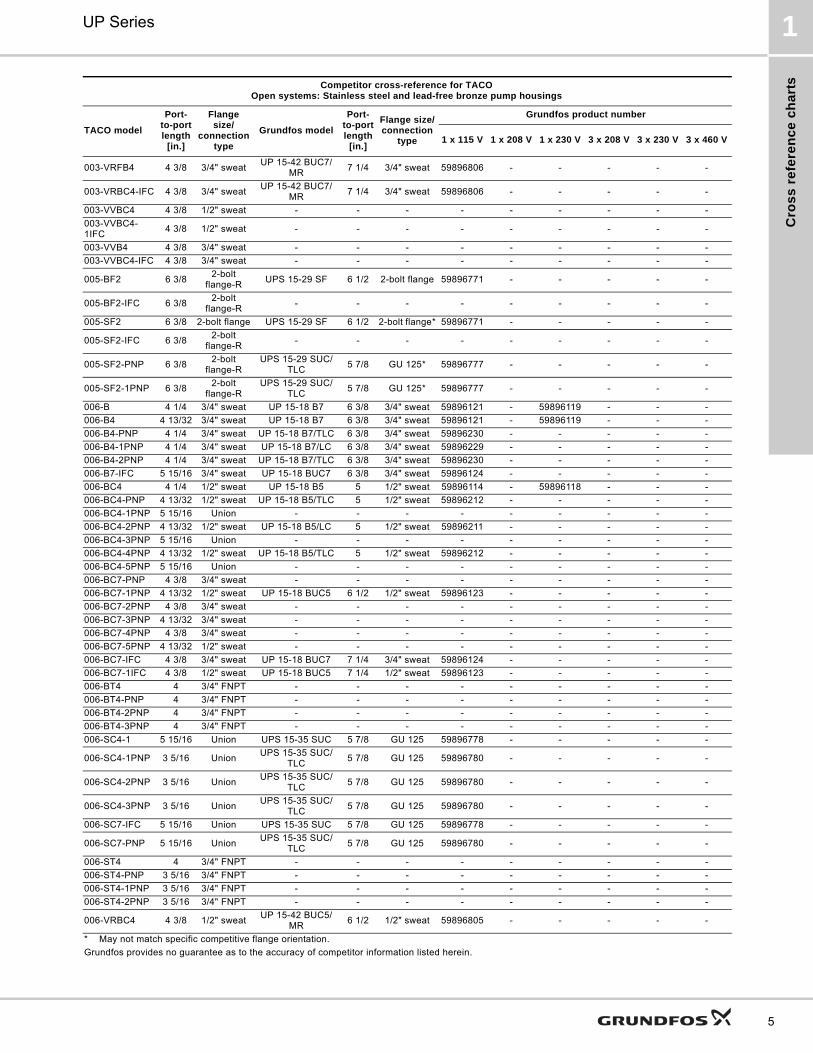
Reference for replacing TACO models
Open systems: Stainless steel and lead-free bronze pump housings
Competitor cross-reference for TACOOpen systems: Stainless steel and lead-free bronze pump housings
TACO model
Port-to-port length
[in.]
Flange size/
connection type
Grundfos model
Port-to-port length
[in.]
Flange size/connection
type
Grundfos product number
1 x 115 V 1 x 208 V 1 x 230 V 3 x 208 V 3 x 230 V 3 x 460 V
00R-SF6-IFC 6 3/8 2-bolt flangeUPS 15-55 SFC 6 1/2 2-bolt flange* 59896773 - - - - -
ALPHA 15-55 SFC 6 1/2 2-bolt flange* 59896879 - - - - -
00R-SF6-1IFC 6 3/82-bolt
flange-RUPS 15-55 SFC 6 1/2 2-bolt flange 59896773 - - - - -
ALPHA 15-55 SFC 6 1/2 2-bolt flange 59896879 - - - - -
003-B4 4 13/32 3/4" sweat UP 15-10 B7 5 3/4" sweat 59896226 - - - - -
003-B4-PNP 3 5/16 3/4" sweat UP 15-10 B7/TLC 5 3/4" sweat 59896210 - - - - -
003-B4-1PNP 3 5/16 3/4" sweat UP 15-10 B7/LC 5 3/4" sweat 59896209 - - - - -
003-B4-2IFC 5 15/16 Union - - - - - - - - -
003-B4-2PNP 3 5/16 3/4" sweat UP 15-10 B7/TLC 5 3/4" sweat 59896210 - - - - -
003-B4-3PNP 5 15/16 Union - - - - - - - - -
003-B4-4PNP 5 15/16 Union - - - - - - - - -
003-BC 4 13/32 1/2" sweat UP 15-10 B5 5 1/2" sweat 59896213 - - - - -
003-BC-1 6 Union - - - - - - - - -
003-BC4 4 1/4 1/2" sweat UP 15-10 B5 5 1/2" sweat 59896213 - - - - -
003-BC4-1 5 15/16 Union - - - - - - - - -
003-BC4-1IFC 4 3/8 1/2" sweat UP 15-10 BUC5 5 1/2" sweat 59896225 - - - - -
003-BC4-IFC 4 3/8 3/4" sweat UP 15-10 BUC7 5 3/4" sweat 59896241 - - - - -
003-BC4-PNP 3 5/16 1/2" sweat UP 15-10 B5/TLC 5 1/2" sweat 59896215 - - - - -
003-BC4-1PNP 5 15/16 Union - - - - - - - - -
003-BC4-2PNP 3 5/16 3/4" sweatUP 15-10 BUC7/
TLC5 3/4" sweat 59896240 - - - - -
003-BC4-3PNP 3 5/16 1/2" sweatUP 15-10 BUC5/
TLC5 1/2" sweat 59896238 - - - - -
003-BC4-4PNP 3 5/16 1/2" sweat UP 15-10 B5/LC 5 1/2" sweat 59896214 - - - - -
003-BC4-5PNP 5 15/16 Union - - - - - - - - -
003-BC4-6PNP 3 5/16 3/4" sweatUP 15-10 BUC7/
LC5 3/4" sweat 59896239 - - - - -
003-BC4-7PNP 3 5/16 1/2" sweatUP 15-10 BUC5/
LC5 1/2" sweat 59896237 - - - - -
003-BC4-8PNP 3 5/16 1/2" sweat UP 15-10 B5/TLC 5 1/2" sweat 59896215 - - - - -
003-BC4-9PNP 5 15/16 Union - - - - - - - - -
003-BC4-10PNP
3 5/16 3/4" sweatUP 15-10 BUC7/
TLC5 3/4" sweat 59896240 - - - - -
003-BC4-11PNP 3 5/16 1/2" sweatUP 15-10 BUC5/
TLC5 1/2" sweat 59896238 - - - - -
003-BT4-PNP 4 3/4" FNPT - - - - - - - - -
003-BT4-1PNP 4 3/4" FNPT - - - - - - - - -
003-BT4-2PNP 4 3/4" FNPT - - - - - - - - -
003-SC4-1 5 15/16 Union UP 15-35 SUC 5 7/8 GU 125 59896778 - - - - -
003-SC4-IFC 5 15/16 Union UP 15-35 SUC 5 7/8 GU 125 59896778 - - - - -
003-SC4-1PNP 3 5/16 UnionUPS 15-35 SUC/
TLC5 7/8 GU 125 59896780 - - - - -
003-SC4-2PNP 3 5/16 UnionUPS 15-35 SUC/
TLC5 7/8 GU 125 59896780 - - - - -
003-SC4-3PNP 3 5/16 UnionUPS 15-35 SUC/
TLC5 7/8 GU 125 59896780 - - - - -
003-SC4-4PNP 3 5/16 UnionUPS 15-35 SUC/
TLC5 7/8 GU 125 59896780 - - - - -
003-ST4 4 3/4" NPT - - - - - - - -
003-ST4-PNP 3 5/16 3/4" FNPT - - - - - - - -
003-ST4-1PNP 3 5/16 3/4" FNPT - - - - - - - -
003-ST4-2PNP 3 5/16 3/4" FNPT - - - - - - - - -
003-VRFBC4 4 3/8 1/2" sweatUP 15-42 BUC5/
MR6 1/2 1/2" sweat 59896805 - - - - -
003-VRBC4-1IFC
4 3/8 1/2" sweatUP 15-42 BUC5/
MR6 1/2 1/2" sweat 59896805 - - - - -
* May not match specific competitive flange orientation.
Grundfos provides no guarantee as to the accuracy of competitor information listed herein.
Cro
ss
re
fere
nc
e c
ha
rts
UP Series 1
5
003-VRFB4 4 3/8 3/4" sweatUP 15-42 BUC7/
MR7 1/4 3/4" sweat 59896806 - - - - -
003-VRBC4-IFC 4 3/8 3/4" sweatUP 15-42 BUC7/
MR7 1/4 3/4" sweat 59896806 - - - - -
003-VVBC4 4 3/8 1/2" sweat - - - - - - - - -
003-VVBC4-1IFC
4 3/8 1/2" sweat - - - - - - - - -
003-VVB4 4 3/8 3/4" sweat - - - - - - - - -
003-VVBC4-IFC 4 3/8 3/4" sweat - - - - - - - - -
005-BF2 6 3/82-bolt
flange-RUPS 15-29 SF 6 1/2 2-bolt flange 59896771 - - - - -
005-BF2-IFC 6 3/82-bolt
flange-R- - - - - - - - -
005-SF2 6 3/8 2-bolt flange UPS 15-29 SF 6 1/2 2-bolt flange* 59896771 - - - - -
005-SF2-IFC 6 3/82-bolt
flange-R- - - - - - - - -
005-SF2-PNP 6 3/82-bolt
flange-RUPS 15-29 SUC/
TLC5 7/8 GU 125* 59896777 - - - - -
005-SF2-1PNP 6 3/82-bolt
flange-RUPS 15-29 SUC/
TLC5 7/8 GU 125* 59896777 - - - - -
006-B 4 1/4 3/4" sweat UP 15-18 B7 6 3/8 3/4" sweat 59896121 - 59896119 - - -
006-B4 4 13/32 3/4" sweat UP 15-18 B7 6 3/8 3/4" sweat 59896121 - 59896119 - - -
006-B4-PNP 4 1/4 3/4" sweat UP 15-18 B7/TLC 6 3/8 3/4" sweat 59896230 - - - - -
006-B4-1PNP 4 1/4 3/4" sweat UP 15-18 B7/LC 6 3/8 3/4" sweat 59896229 - - - - -
006-B4-2PNP 4 1/4 3/4" sweat UP 15-18 B7/TLC 6 3/8 3/4" sweat 59896230 - - - - -
006-B7-IFC 5 15/16 3/4" sweat UP 15-18 BUC7 6 3/8 3/4" sweat 59896124 - - - - -
006-BC4 4 1/4 1/2" sweat UP 15-18 B5 5 1/2" sweat 59896114 - 59896118 - - -
006-BC4-PNP 4 13/32 1/2" sweat UP 15-18 B5/TLC 5 1/2" sweat 59896212 - - - - -
006-BC4-1PNP 5 15/16 Union - - - - - - - - -
006-BC4-2PNP 4 13/32 1/2" sweat UP 15-18 B5/LC 5 1/2" sweat 59896211 - - - - -
006-BC4-3PNP 5 15/16 Union - - - - - - - - -
006-BC4-4PNP 4 13/32 1/2" sweat UP 15-18 B5/TLC 5 1/2" sweat 59896212 - - - - -
006-BC4-5PNP 5 15/16 Union - - - - - - - - -
006-BC7-PNP 4 3/8 3/4" sweat - - - - - - - - -
006-BC7-1PNP 4 13/32 1/2" sweat UP 15-18 BUC5 6 1/2 1/2" sweat 59896123 - - - - -
006-BC7-2PNP 4 3/8 3/4" sweat - - - - - - - - -
006-BC7-3PNP 4 13/32 3/4" sweat - - - - - - - - -
006-BC7-4PNP 4 3/8 3/4" sweat - - - - - - - - -
006-BC7-5PNP 4 13/32 1/2" sweat - - - - - - - - -
006-BC7-IFC 4 3/8 3/4" sweat UP 15-18 BUC7 7 1/4 3/4" sweat 59896124 - - - - -
006-BC7-1IFC 4 3/8 1/2" sweat UP 15-18 BUC5 7 1/4 1/2" sweat 59896123 - - - - -
006-BT4 4 3/4" FNPT - - - - - - - - -
006-BT4-PNP 4 3/4" FNPT - - - - - - - - -
006-BT4-2PNP 4 3/4" FNPT - - - - - - - - -
006-BT4-3PNP 4 3/4" FNPT - - - - - - - - -
006-SC4-1 5 15/16 Union UPS 15-35 SUC 5 7/8 GU 125 59896778 - - - - -
006-SC4-1PNP 3 5/16 UnionUPS 15-35 SUC/
TLC5 7/8 GU 125 59896780 - - - - -
006-SC4-2PNP 3 5/16 UnionUPS 15-35 SUC/
TLC5 7/8 GU 125 59896780 - - - - -
006-SC4-3PNP 3 5/16 UnionUPS 15-35 SUC/
TLC5 7/8 GU 125 59896780 - - - - -
006-SC7-IFC 5 15/16 Union UPS 15-35 SUC 5 7/8 GU 125 59896778 - - - - -
006-SC7-PNP 5 15/16 UnionUPS 15-35 SUC/
TLC5 7/8 GU 125 59896780 - - - - -
006-ST4 4 3/4" FNPT - - - - - - - - -
006-ST4-PNP 3 5/16 3/4" FNPT - - - - - - - - -
006-ST4-1PNP 3 5/16 3/4" FNPT - - - - - - - - -
006-ST4-2PNP 3 5/16 3/4" FNPT - - - - - - - - -
006-VRBC4 4 3/8 1/2" sweatUP 15-42 BUC5/
MR6 1/2 1/2" sweat 59896805 - - - - -
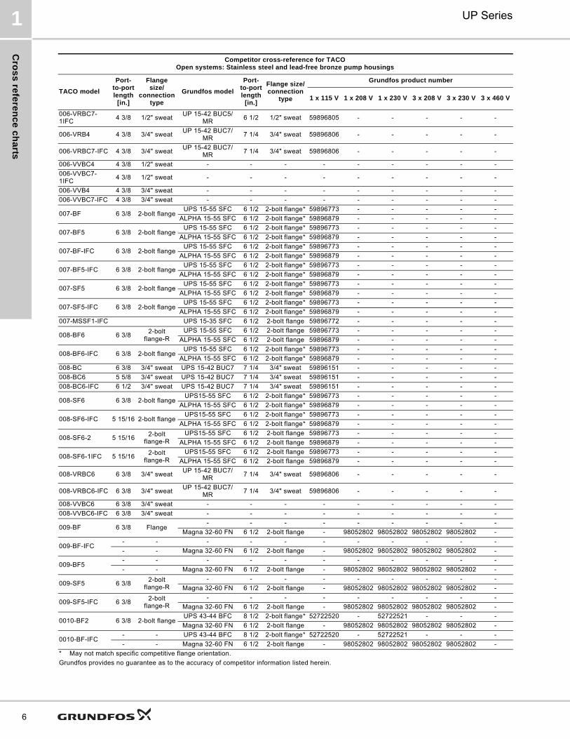
Competitor cross-reference for TACOOpen systems: Stainless steel and lead-free bronze pump housings
TACO model
Port-to-port length
[in.]
Flange size/
connection type
Grundfos model
Port-to-port length
[in.]
Flange size/connection
type
Grundfos product number
1 x 115 V 1 x 208 V 1 x 230 V 3 x 208 V 3 x 230 V 3 x 460 V
* May not match specific competitive flange orientation.
Grundfos provides no guarantee as to the accuracy of competitor information listed herein.
Cro
ss
refe
ren
ce
ch
arts
UP Series1
6
006-VRBC7-1IFC
4 3/8 1/2" sweatUP 15-42 BUC5/
MR6 1/2 1/2" sweat 59896805 - - - - -
006-VRB4 4 3/8 3/4" sweatUP 15-42 BUC7/
MR7 1/4 3/4" sweat 59896806 - - - - -
006-VRBC7-IFC 4 3/8 3/4" sweatUP 15-42 BUC7/
MR7 1/4 3/4" sweat 59896806 - - - - -
006-VVBC4 4 3/8 1/2" sweat - - - - - - - - -
006-VVBC7-1IFC
4 3/8 1/2" sweat - - - - - - - - -
006-VVB4 4 3/8 3/4" sweat - - - - - - - - -
006-VVBC7-IFC 4 3/8 3/4" sweat - - - - - - - - -
007-BF 6 3/8 2-bolt flangeUPS 15-55 SFC 6 1/2 2-bolt flange* 59896773 - - - - -
ALPHA 15-55 SFC 6 1/2 2-bolt flange* 59896879 - - - - -
007-BF5 6 3/8 2-bolt flangeUPS 15-55 SFC 6 1/2 2-bolt flange* 59896773 - - - - -
ALPHA 15-55 SFC 6 1/2 2-bolt flange* 59896879 - - - - -
007-BF-IFC 6 3/8 2-bolt flangeUPS 15-55 SFC 6 1/2 2-bolt flange* 59896773 - - - - -
ALPHA 15-55 SFC 6 1/2 2-bolt flange* 59896879 - - - - -
007-BF5-IFC 6 3/8 2-bolt flangeUPS 15-55 SFC 6 1/2 2-bolt flange* 59896773 - - - - -
ALPHA 15-55 SFC 6 1/2 2-bolt flange* 59896879 - - - - -
007-SF5 6 3/8 2-bolt flangeUPS 15-55 SFC 6 1/2 2-bolt flange* 59896773 - - - - -
ALPHA 15-55 SFC 6 1/2 2-bolt flange* 59896879 - - - - -
007-SF5-IFC 6 3/8 2-bolt flangeUPS 15-55 SFC 6 1/2 2-bolt flange* 59896773 - - - - -
ALPHA 15-55 SFC 6 1/2 2-bolt flange* 59896879 - - - - -
007-MSSF1-IFC UPS 15-35 SFC 6 1/2 2-bolt flange 59896772 - - - - -
008-BF6 6 3/82-bolt
flange-RUPS 15-55 SFC 6 1/2 2-bolt flange 59896773 - - - - -
ALPHA 15-55 SFC 6 1/2 2-bolt flange 59896879 - - - - -
008-BF6-IFC 6 3/8 2-bolt flangeUPS 15-55 SFC 6 1/2 2-bolt flange* 59896773 - - - - -
ALPHA 15-55 SFC 6 1/2 2-bolt flange* 59896879 - - - - -
008-BC 6 3/8 3/4" sweat UPS 15-42 BUC7 7 1/4 3/4" sweat 59896151 - - - - -
008-BC6 5 5/8 3/4" sweat UPS 15-42 BUC7 7 1/4 3/4" sweat 59896151 - - - - -
008-BC6-IFC 6 1/2 3/4" sweat UPS 15-42 BUC7 7 1/4 3/4" sweat 59896151 - - - - -
008-SF6 6 3/8 2-bolt flangeUPS15-55 SFC 6 1/2 2-bolt flange* 59896773 - - - - -
ALPHA 15-55 SFC 6 1/2 2-bolt flange* 59896879 - - - - -
008-SF6-IFC 5 15/16 2-bolt flangeUPS15-55 SFC 6 1/2 2-bolt flange* 59896773 - - - - -
ALPHA 15-55 SFC 6 1/2 2-bolt flange* 59896879 - - - - -
008-SF6-2 5 15/162-bolt
flange-RUPS15-55 SFC 6 1/2 2-bolt flange 59896773 - - - - -
ALPHA 15-55 SFC 6 1/2 2-bolt flange 59896879 - - - - -
008-SF6-1IFC 5 15/162-bolt
flange-RUPS15-55 SFC 6 1/2 2-bolt flange 59896773 - - - - -
ALPHA 15-55 SFC 6 1/2 2-bolt flange 59896879 - - - - -
008-VRBC6 6 3/8 3/4" sweatUP 15-42 BUC7/
MR7 1/4 3/4" sweat 59896806 - - - - -
008-VRBC6-IFC 6 3/8 3/4" sweatUP 15-42 BUC7/
MR7 1/4 3/4" sweat 59896806 - - - - -
008-VVBC6 6 3/8 3/4" sweat - - - - - - - - -
008-VVBC6-IFC 6 3/8 3/4" sweat - - - - - - - - -
009-BF 6 3/8 Flange- - - - - - - - -
Magna 32-60 FN 6 1/2 2-bolt flange - 98052802 98052802 98052802 98052802 -
009-BF-IFC- - - - - - - - - - -
- - Magna 32-60 FN 6 1/2 2-bolt flange - 98052802 98052802 98052802 98052802 -
009-BF5- - - - - - - - - - -
- - Magna 32-60 FN 6 1/2 2-bolt flange - 98052802 98052802 98052802 98052802 -
009-SF5 6 3/82-bolt
flange-R- - - - - - - - -
Magna 32-60 FN 6 1/2 2-bolt flange - 98052802 98052802 98052802 98052802 -
009-SF5-IFC 6 3/82-bolt
flange-R- - - - - - - - -
Magna 32-60 FN 6 1/2 2-bolt flange - 98052802 98052802 98052802 98052802 -
0010-BF2 6 3/8 2-bolt flangeUPS 43-44 BFC 8 1/2 2-bolt flange* 52722520 - 52722521 - - -
Magna 32-60 FN 6 1/2 2-bolt flange - 98052802 98052802 98052802 98052802 -
0010-BF-IFC- - UPS 43-44 BFC 8 1/2 2-bolt flange* 52722520 - 52722521 - - -
- - Magna 32-60 FN 6 1/2 2-bolt flange - 98052802 98052802 98052802 98052802 -
Competitor cross-reference for TACOOpen systems: Stainless steel and lead-free bronze pump housings
TACO model
Port-to-port length
[in.]
Flange size/
connection type
Grundfos model
Port-to-port length
[in.]
Flange size/connection
type
Grundfos product number
1 x 115 V 1 x 208 V 1 x 230 V 3 x 208 V 3 x 230 V 3 x 460 V
* May not match specific competitive flange orientation.
Grundfos provides no guarantee as to the accuracy of competitor information listed herein.

Cro
ss
re
fere
nc
e c
ha
rts
UP Series 1
7
0010-BF3 6 3/82-bolt
flange-RUPS 43-44 BFC 8 1/2 2-bolt flange 52722520 - 52722521 - - -
Magna 32-60 FN 6 1/2 2-bolt flange - 98052802 98052802 98052802 98052802 -
0010-SF3 6 3/8 2-bolt flangeUPS 43-44 BFC 8 1/2 2-bolt flange* 52722520 - 52722521 - - -
Magna 32-60 FN 6 1/2 2-bolt flange - 98052802 98052802 98052802 98052802 -
0010-SF3-IFC 6 3/8 2-bolt flangeUPS 43-44 BFC 8 1/2 2-bolt flange* 52722520 - 52722521 - - -
Magna 32-60 FN 6 1/2 2-bolt flange - 98052802 98052802 98052802 98052802 -
0011-BF4 6 1/2 2-bolt flangeUPS 26-99 BFC 6 1/2 2-bolt flange* 52722518 - 52722519 - - -
Magna 32-60 FN 6 1/2 2-bolt flange - 98052802 98052802 98052802 98052802 -
0011-BF-IFC- - UPS 26-99 BFC 6 1/2 2-bolt flange* 52722518 - 52722519 - - -
- - Magna 32-60 FN 6 1/2 2-bolt flange - 98052802 98052802 98052802 98052802 -
0011-SF4 6 3/82-bolt
flange-RUPS 26-99 BFC 6 1/2 2-bolt flange 52722518 - 52722519 - - -
Magna 32-60 FN 6 1/2 2-bolt flange - 98052802 98052802 98052802 98052802 -
0011-SF4-IFC 6 1/22-bolt
flange-RUPS 26-99 BFC 6 1/2 2-bolt flange 52722518 - 52722519 - - -
Magna 32-60 FN 6 1/2 2-bolt flange - 98052802 98052802 98052802 98052802 -
0012-BF 8 1/22-bolt
flange-RUPS 43-44 BFC 8 1/2 2-bolt flange 52722520 - 52722521 - - -
Magna 40-120 FN 8 1/2 3/4" to 1 1/2" - - 96734633 - 96734633 -
0012-BF4-IFC 8 1/2 2-bolt
flange-RUPS 43-44 BFC 8 1/2 2-bolt flange 52722520 - 52722521 - - -
Magna 40-120 FN 8 1/2 3/4" to 1 1/2" - - 96734633 - 96734633 -
0012-BF4 8 1/2 2-bolt flangeUPS 43-44 BFC 8 1/2 2-bolt flange* 52722520 - 52722521 - - -
Magna 40-120 FN 8 1/2 3/4" to 1 1/2" - - 96734633 - 96734633 -
0012-BF4-1 8 1/2 2" flangeUPS 43-44 BFC 8 1/2 2-bolt flange* 52722520 - 52722521 - - -
Magna 40-120 FN 8 1/2 3/4" to 1 1/2" - - 96734633 - 96734633 -
0012-SF4 8 1/2 1 1/2" flangeUPS 43-44 BFC 8 1/2 2-bolt flange* 52722520 - 52722521 - - -
Magna 40-120 FN 8 1/2 3/4" to 1 1/2" - - 96734633 - 96734633 -
0012-SF4-IFC 8 1/2 1 1/2" flangeUPS 43-44 BFC 8 1/2 2-bolt flange* 52722520 - 52722521 - - -
Magna 40-120 FN 8 1/2 3/4" to 1 1/2" - - 96734633 - 96734633 -
0012-VRBF4-1 6 1/2 2" flange- - - - - - - - -
Magna 40-120 FN 8 1/2 3/4" to 1 1/2" - - 96734633 - 96734633 -
0012-VVBF4-1 6 1/2 2" flange- - - - - - - - -
Magna 40-120 FN 8 1/2 3/4" to 1 1/2" - - 96734633 - 96734633 -
0013-BF3 6 1/2 2-bolt flangeUPS 26-150 SF 8 1/2 2-bolt flange* 95906632 - 95906633 - 95906633 -
Magna 32-100 FN 6 1/2 2-bolt flange - 98052760 98052760 98052760 98052760 -
0013-BF-IFC 6 1/2 2-bolt flangeUPS 26-150 SF 8 1/2 2-bolt flange* 95906632 - 95906633 - 95906633 -
Magna 32-100 FN 6 1/2 2-bolt flange - 98052760 98052760 98052760 98052760 -
0013-SF3 6 1/22-bolt
flange-RUPS 26-150 SF 8 1/2 2-bolt flange 95906632 - 95906633 - 95906633 -
Magna 32-100 FN 6 1/2 2-bolt flange - 98052760 98052760 98052760 98052760 -
0013-SF3-IFC 6 1/22-bolt
flange-RUPS 26-150 SF 8 1/2 2-bolt flange 95906632 - 95906633 - 95906633 -
Magna 32-100 FN 6 1/2 2-bolt flange - 98052760 98052760 98052760 98052760 -
0014-BF 6 1/22-bolt
flange-RUPS 26-99 BFC 6 1/2 2-bolt flange 52722518 - 52722519 - 52722519 -
Magna 32-100 FN 6 1/2 2-bolt flange - 98052760 98052760 98052760 98052760 -
0014-BF-1 6 1/2 2-bolt flangeUPS 26-99 BFC 6 1/2 2-bolt flange* 52722518 - 52722519 - 52722519 -
Magna 32-100 FN 6 1/2 2-bolt flange - 98052760 98052760 98052760 98052760 -
0014-BF1-1IFC 6 1/2 2-bolt flangeUPS 26-99 BFC 6 1/2 2-bolt flange* 52722518 - 52722519 - 52722519 -
Magna 32-100 FN 6 1/2 2-bolt flange - 98052760 98052760 98052760 98052760 -
0014-SF1 6 1/2 2-bolt
flange-RUPS 26-99 BFC 6 1/2 2-bolt flange 52722518 - 52722519 - 52722519 -
Magna 32-100 FN 6 1/2 2-bolt flange - 98052760 98052760 98052760 98052760 -
0014-SF1-1IFC 6 1/2 2-bolt
flange-RUPS 26-99 BFC 6 1/2 2-bolt flange 52722518 - 52722519 - 52722519 -
Magna 32-100 FN 6 1/2 2-bolt flange - 98052760 98052760 98052760 98052760 -
0015-MSSF2-IFC
6 1/2 2-bolt flange UPS 15-55 SFC 6 1/2 2-bolt flange* 59896773 - - - - -
0015-MSSF2-1IFC
6 1/2 2-bolt
flange-RUPS 15-55 SFC 6 1/2 2-bolt flange 59896773 - - - - -
1400-10B 6 3/82-bolt
flange-RUPS 26-99 BFC 6 1/2 2-bolt flange 52722518 - 52722519 - 52722519 -
Magna 32-60 FN 6 1/2 2-bolt flange - 98052802 98052802 98052802 98052802 -
1400-20B 6 3/82-bolt
flange-RUPS 26-150 SF 6 1/2 2-bolt flange 95906632 95906633 95906633 - - -
Magna 32-100 FN 6 1/2 2-bolt flange - 98052760 98052760 98052760 98052760 -
1400-30B 8 1/22-bolt
flange-RUPS 26-150 SF 6 1/2 2-bolt flange 95906632 95906633 95906633 - - -
Magna 32-100 FN 6 1/2 2-bolt flange - 98052760 98052760 98052760 98052760 -
1400-40B 8 1/22-bolt
flange-RUPS 43-100 SF 8 1/2 2-bolt flange 95906638 95906639 95906639 - - -
Magna 32-100 FN 6 1/2 2-bolt flange - 98052760 98052760 98052760 98052760 -
Competitor cross-reference for TACOOpen systems: Stainless steel and lead-free bronze pump housings
TACO model
Port-to-port length
[in.]
Flange size/
connection type
Grundfos model
Port-to-port length
[in.]
Flange size/connection
type
Grundfos product number
1 x 115 V 1 x 208 V 1 x 230 V 3 x 208 V 3 x 230 V 3 x 460 V
* May not match specific competitive flange orientation.
Grundfos provides no guarantee as to the accuracy of competitor information listed herein.
Cro
ss
refe
ren
ce
ch
arts
UP Series1
8
1400-45B 6 3/82-bolt
flange-RUPS 26-150 SF 6 1/2 2-bolt flange 95906632 95906633 95906633 - - -
Magna 40-120 FN 8 1/2 3/4" to 1 1/2" - - 96734633 - 96734633 -
1400-50B 6 3/82" bolt flange
UPS 40-160/2 B 11 1/22" 4-bolt flange*
96402787 96402788 96402787 96402788 - -
Magna 40-120 FN 8 1/2 3/4" to 1 1/2" - - 96734633 - 96734633 -
1400-50B/2 6 3/82" bolt flange
UPS 40-160/2 B 11 1/22" 4-bolt flange*
96402787 - 96402788 96402789 96402789 96402790
1400-60B 8 1/22-bolt
flange-RUPS 43-100 SF 8 1/2 2-bolt flange 95906638 95906639 95906639 - - -
1400-65B 8 1/22-bolt
flange-RUPS 50-60 SF 8 1/2 4-bolt flange 97523136 97523137 97523137 - - -
1400-70B 8 1/2 4-bolt flange UPS 50-80/4 B 11 1/22" 4-bolt flange*
96404963 - 96404964 96404965 96404965 96404966
1400-70B/3 8 1/2 4-bolt flange UPS 50-80/4 B 11 1/22" 4-bolt flange*
96404963 - 96404964 96404965 96404965 96404966
2400-10S 6 3/82-bolt
flange-RUPS 26-99 BFC 6 1/2 2-bolt flange 52722518 - 52722519 - - -
Magna 32-60 FN 6 1/2 2-bolt flange - 98052802 98052802 98052802 98052802 -
2400-20S 6 3/82-bolt
flange-RUPS 26-150 SF 6 1/2 2-bolt flange 95906632 95906633 95906633 - - -
Magna 32-100 FN 6 1/2 2-bolt flange - 98052760 98052760 98052760 98052760 -
2400-30S 8 1/22-bolt
flange-RUPS 26-150 SF 6 1/2 2-bolt flange 95906632 95906633 95906633 - - -
Magna 32-100 FN 6 1/2 2-bolt flange - 98052760 98052760 98052760 98052760 -
2400-40S 8 1/22-bolt
flange-RUPS 43-100 SF 8 1/2 2-bolt flange 95906638 95906639 95906639 - - -
Magna 32-100 FN 6 1/2 2-bolt flange - 98052760 98052760 98052760 98052760 -
2400-45S 6 3/82-bolt
flange-RUPS 26-150 SF 6 1/2 2-bolt flange 95906632 95906633 95906633 - - -
Magna 40-120 FN 8 1/2 3/4" to 1 1/2" - - 96734633 - 96734633 -
2400-50S 6 3/82-bolt
flange-RUPS 40-160/2 B 11 1/2
2" 4-bolt flange*
96402787 - 96402788 96402789 96402789 96402790
Magna 40-120 FN 8 1/2 3/4" to 1 1/2" - - 96734633 - 96734633 -
2400-50S/2 6 3/82" 2-bolt flange
UPS 40-160/2 B 11 1/22" 4-bolt flange*
96402787 96402788 96402789 96402789 96402790
2400-60S 8 1/22" 4-bolt flange
UPS 43-100 SF 8 1/2 2-bolt flange 95906638 95906639 95906639 - - -
2400-65S 8 1/22" 4-bolt flange
UPS 50-60 SF 8 1/2 4-bolt flange 97523136 97523137 97523137 - - -
2400-70S 8 1/22" 4-bolt flange
UPS 50-80/4 B 11 1/22" 4-bolt flange*
96404963 - 96404964 96404965 96404965 96404966
2400-70S/3 8 1/23" 4-bolt flange
UPS 50-80/4 B 11 1/22" 4-bolt flange*
96404963 - 96404964 96404965 96404965 96404966
Competitor cross-reference for TACOOpen systems: Stainless steel and lead-free bronze pump housings
TACO model
Port-to-port length
[in.]
Flange size/
connection type
Grundfos model
Port-to-port length
[in.]
Flange size/connection
type
Grundfos product number
1 x 115 V 1 x 208 V 1 x 230 V 3 x 208 V 3 x 230 V 3 x 460 V
* May not match specific competitive flange orientation.
Grundfos provides no guarantee as to the accuracy of competitor information listed herein.
Cro
ss
re
fere
nc
e c
ha
rts
UP Series 1
9
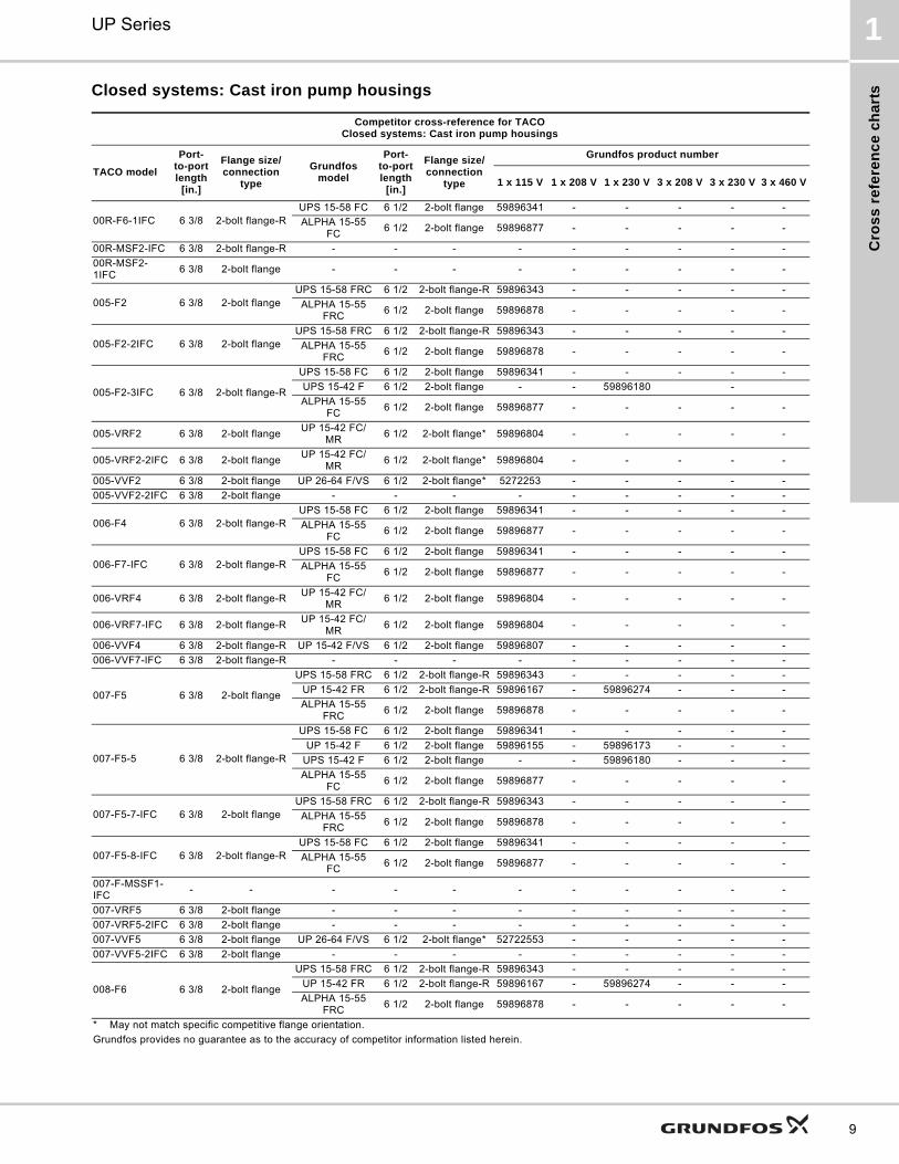
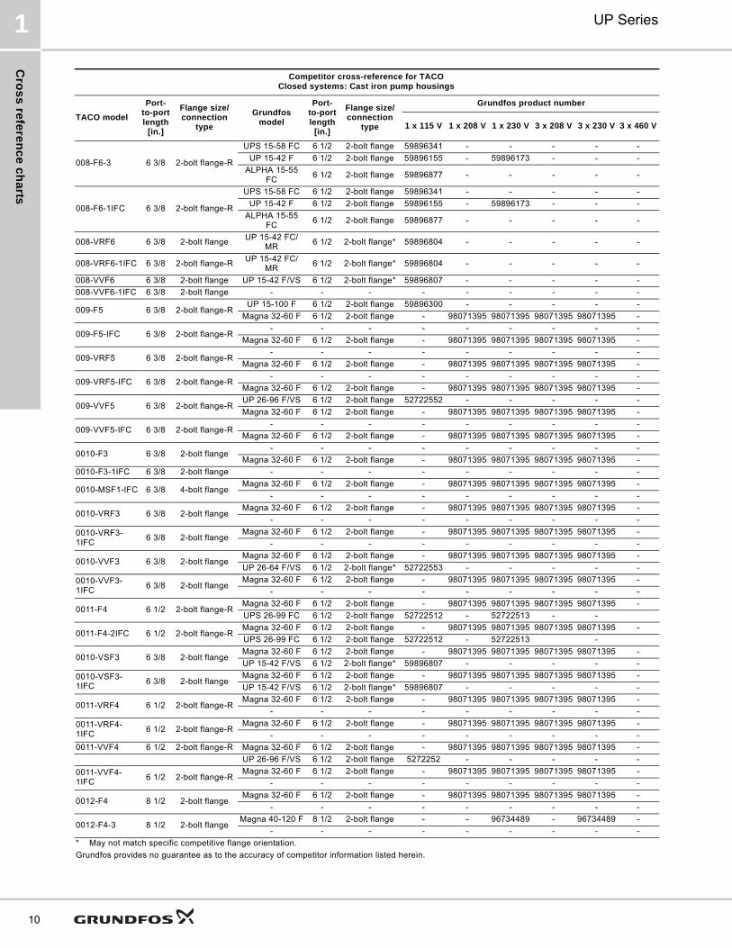
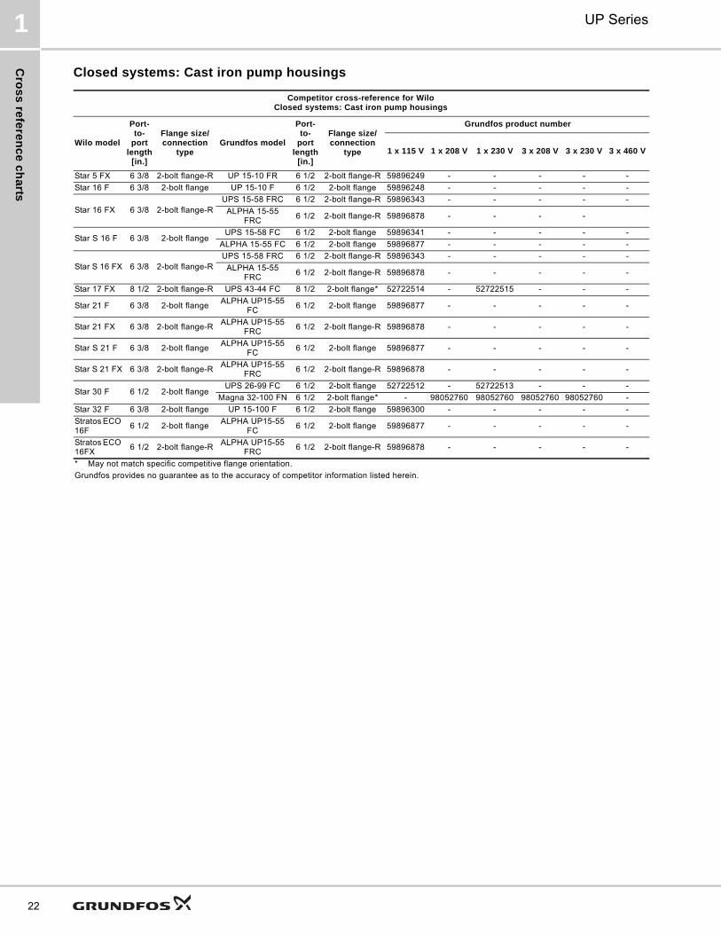
Closed systems: Cast iron pump housings
Competitor cross-reference for TACOClosed systems: Cast iron pump housings
TACO model
Port-to-port length
[in.]
Flange size/connection
type
Grundfos model
Port-to-port length
[in.]
Flange size/connection
type
Grundfos product number
1 x 115 V 1 x 208 V 1 x 230 V 3 x 208 V 3 x 230 V 3 x 460 V
00R-F6-1IFC 6 3/8 2-bolt flange-RUPS 15-58 FC 6 1/2 2-bolt flange 59896341 - - - - -
ALPHA 15-55 FC
6 1/2 2-bolt flange 59896877 - - - - -
00R-MSF2-IFC 6 3/8 2-bolt flange-R - - - - - - - - -
00R-MSF2-1IFC
6 3/8 2-bolt flange - - - - - - - - -
005-F2 6 3/8 2-bolt flangeUPS 15-58 FRC 6 1/2 2-bolt flange-R 59896343 - - - - -
ALPHA 15-55 FRC
6 1/2 2-bolt flange 59896878 - - - - -
005-F2-2IFC 6 3/8 2-bolt flangeUPS 15-58 FRC 6 1/2 2-bolt flange-R 59896343 - - - - -
ALPHA 15-55 FRC
6 1/2 2-bolt flange 59896878 - - - - -
005-F2-3IFC 6 3/8 2-bolt flange-R
UPS 15-58 FC 6 1/2 2-bolt flange 59896341 - - - - -
UPS 15-42 F 6 1/2 2-bolt flange - - 59896180 -
ALPHA 15-55 FC
6 1/2 2-bolt flange 59896877 - - - - -
005-VRF2 6 3/8 2-bolt flangeUP 15-42 FC/
MR6 1/2 2-bolt flange* 59896804 - - - - -
005-VRF2-2IFC 6 3/8 2-bolt flangeUP 15-42 FC/
MR6 1/2 2-bolt flange* 59896804 - - - - -
005-VVF2 6 3/8 2-bolt flange UP 26-64 F/VS 6 1/2 2-bolt flange* 5272253 - - - - -
005-VVF2-2IFC 6 3/8 2-bolt flange - - - - - - - - -
006-F4 6 3/8 2-bolt flange-RUPS 15-58 FC 6 1/2 2-bolt flange 59896341 - - - - -
ALPHA 15-55 FC
6 1/2 2-bolt flange 59896877 - - - - -
006-F7-IFC 6 3/8 2-bolt flange-RUPS 15-58 FC 6 1/2 2-bolt flange 59896341 - - - - -
ALPHA 15-55 FC
6 1/2 2-bolt flange 59896877 - - - - -
006-VRF4 6 3/8 2-bolt flange-RUP 15-42 FC/
MR6 1/2 2-bolt flange 59896804 - - - - -
006-VRF7-IFC 6 3/8 2-bolt flange-RUP 15-42 FC/
MR6 1/2 2-bolt flange 59896804 - - - - -
006-VVF4 6 3/8 2-bolt flange-R UP 15-42 F/VS 6 1/2 2-bolt flange 59896807 - - - - -
006-VVF7-IFC 6 3/8 2-bolt flange-R - - - - - - - - -
007-F5 6 3/8 2-bolt flange
UPS 15-58 FRC 6 1/2 2-bolt flange-R 59896343 - - - - -
UP 15-42 FR 6 1/2 2-bolt flange-R 59896167 - 59896274 - - -
ALPHA 15-55 FRC
6 1/2 2-bolt flange 59896878 - - - - -
007-F5-5 6 3/8 2-bolt flange-R
UPS 15-58 FC 6 1/2 2-bolt flange 59896341 - - - - -
UP 15-42 F 6 1/2 2-bolt flange 59896155 - 59896173 - - -
UPS 15-42 F 6 1/2 2-bolt flange - - 59896180 - - -
ALPHA 15-55 FC
6 1/2 2-bolt flange 59896877 - - - - -
007-F5-7-IFC 6 3/8 2-bolt flangeUPS 15-58 FRC 6 1/2 2-bolt flange-R 59896343 - - - - -
ALPHA 15-55 FRC
6 1/2 2-bolt flange 59896878 - - - - -
007-F5-8-IFC 6 3/8 2-bolt flange-RUPS 15-58 FC 6 1/2 2-bolt flange 59896341 - - - - -
ALPHA 15-55 FC
6 1/2 2-bolt flange 59896877 - - - - -
007-F-MSSF1-IFC
- - - - - - - - - - -
007-VRF5 6 3/8 2-bolt flange - - - - - - - - -
007-VRF5-2IFC 6 3/8 2-bolt flange - - - - - - - - -
007-VVF5 6 3/8 2-bolt flange UP 26-64 F/VS 6 1/2 2-bolt flange* 52722553 - - - - -
007-VVF5-2IFC 6 3/8 2-bolt flange - - - - - - - - -
008-F6 6 3/8 2-bolt flange
UPS 15-58 FRC 6 1/2 2-bolt flange-R 59896343 - - - - -
UP 15-42 FR 6 1/2 2-bolt flange-R 59896167 - 59896274 - - -
ALPHA 15-55 FRC
6 1/2 2-bolt flange 59896878 - - - - -
* May not match specific competitive flange orientation.
Grundfos provides no guarantee as to the accuracy of competitor information listed herein.
Cro
ss
refe
ren
ce
ch
arts
UP Series1
10
008-F6-3 6 3/8 2-bolt flange-R
UPS 15-58 FC 6 1/2 2-bolt flange 59896341 - - - - -
UP 15-42 F 6 1/2 2-bolt flange 59896155 - 59896173 - - -
ALPHA 15-55 FC
6 1/2 2-bolt flange 59896877 - - - - -
008-F6-1IFC 6 3/8 2-bolt flange-R
UPS 15-58 FC 6 1/2 2-bolt flange 59896341 - - - - -
UP 15-42 F 6 1/2 2-bolt flange 59896155 - 59896173 - - -
ALPHA 15-55 FC
6 1/2 2-bolt flange 59896877 - - - - -
008-VRF6 6 3/8 2-bolt flangeUP 15-42 FC/
MR6 1/2 2-bolt flange* 59896804 - - - - -
008-VRF6-1IFC 6 3/8 2-bolt flange-RUP 15-42 FC/
MR6 1/2 2-bolt flange* 59896804 - - - - -
008-VVF6 6 3/8 2-bolt flange UP 15-42 F/VS 6 1/2 2-bolt flange* 59896807 - - - - -
008-VVF6-1IFC 6 3/8 2-bolt flange - - - - - - - - -
009-F5 6 3/8 2-bolt flange-RUP 15-100 F 6 1/2 2-bolt flange 59896300 - - - - -
Magna 32-60 F 6 1/2 2-bolt flange - 98071395 98071395 98071395 98071395 -
009-F5-IFC 6 3/8 2-bolt flange-R- - - - - - - - -
Magna 32-60 F 6 1/2 2-bolt flange - 98071395 98071395 98071395 98071395 -
009-VRF5 6 3/8 2-bolt flange-R- - - - - - - - -
Magna 32-60 F 6 1/2 2-bolt flange - 98071395 98071395 98071395 98071395 -
009-VRF5-IFC 6 3/8 2-bolt flange-R- - - - - - - - -
Magna 32-60 F 6 1/2 2-bolt flange - 98071395 98071395 98071395 98071395 -
009-VVF5 6 3/8 2-bolt flange-RUP 26-96 F/VS 6 1/2 2-bolt flange 52722552 - - - - -
Magna 32-60 F 6 1/2 2-bolt flange - 98071395 98071395 98071395 98071395 -
009-VVF5-IFC 6 3/8 2-bolt flange-R- - - - - - - - -
Magna 32-60 F 6 1/2 2-bolt flange - 98071395 98071395 98071395 98071395 -
0010-F3 6 3/8 2-bolt flange- - - - - - - - -
Magna 32-60 F 6 1/2 2-bolt flange - 98071395 98071395 98071395 98071395 -
0010-F3-1IFC 6 3/8 2-bolt flange - - - - - - - - -
0010-MSF1-IFC 6 3/8 4-bolt flangeMagna 32-60 F 6 1/2 2-bolt flange - 98071395 98071395 98071395 98071395 -
- - - - - - - - -
0010-VRF3 6 3/8 2-bolt flangeMagna 32-60 F 6 1/2 2-bolt flange - 98071395 98071395 98071395 98071395 -
- - - - - - - - -
0010-VRF3-1IFC
6 3/8 2-bolt flangeMagna 32-60 F 6 1/2 2-bolt flange - 98071395 98071395 98071395 98071395 -
- - - - - - - - -
0010-VVF3 6 3/8 2-bolt flangeMagna 32-60 F 6 1/2 2-bolt flange - 98071395 98071395 98071395 98071395 -
UP 26-64 F/VS 6 1/2 2-bolt flange* 52722553 - - - - -
0010-VVF3-1IFC
6 3/8 2-bolt flangeMagna 32-60 F 6 1/2 2-bolt flange - 98071395 98071395 98071395 98071395 -
- - - - - - - - -
0011-F4 6 1/2 2-bolt flange-RMagna 32-60 F 6 1/2 2-bolt flange - 98071395 98071395 98071395 98071395 -
UPS 26-99 FC 6 1/2 2-bolt flange 52722512 - 52722513 - -
0011-F4-2IFC 6 1/2 2-bolt flange-RMagna 32-60 F 6 1/2 2-bolt flange - 98071395 98071395 98071395 98071395 -
UPS 26-99 FC 6 1/2 2-bolt flange 52722512 - 52722513 -
0010-VSF3 6 3/8 2-bolt flangeMagna 32-60 F 6 1/2 2-bolt flange - 98071395 98071395 98071395 98071395 -
UP 15-42 F/VS 6 1/2 2-bolt flange* 59896807 - - - - -
0010-VSF3-1IFC
6 3/8 2-bolt flangeMagna 32-60 F 6 1/2 2-bolt flange - 98071395 98071395 98071395 98071395 -
UP 15-42 F/VS 6 1/2 2-bolt flange* 59896807 - - - - -
0011-VRF4 6 1/2 2-bolt flange-RMagna 32-60 F 6 1/2 2-bolt flange - 98071395 98071395 98071395 98071395 -
- - - - - - - - -
0011-VRF4-1IFC
6 1/2 2-bolt flange-RMagna 32-60 F 6 1/2 2-bolt flange - 98071395 98071395 98071395 98071395 -
- - - - - - - - -
0011-VVF4 6 1/2 2-bolt flange-R Magna 32-60 F 6 1/2 2-bolt flange - 98071395 98071395 98071395 98071395 -
UP 26-96 F/VS 6 1/2 2-bolt flange 5272252 - - - - -
0011-VVF4-1IFC
6 1/2 2-bolt flange-RMagna 32-60 F 6 1/2 2-bolt flange - 98071395 98071395 98071395 98071395 -
- - - - - - - - -
0012-F4 8 1/2 2-bolt flangeMagna 32-60 F 6 1/2 2-bolt flange - 98071395 98071395 98071395 98071395 -
- - - - - - - - -
0012-F4-3 8 1/2 2-bolt flangeMagna 40-120 F 8 1/2 2-bolt flange - - 96734489 - 96734489 -
- - - - - - - - -
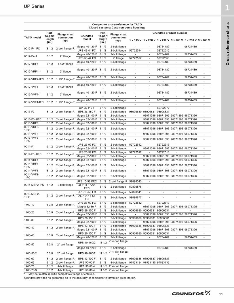
Competitor cross-reference for TACOClosed systems: Cast iron pump housings
TACO model
Port-to-port length
[in.]
Flange size/connection
type
Grundfos model
Port-to-port length
[in.]
Flange size/connection
type
Grundfos product number
1 x 115 V 1 x 208 V 1 x 230 V 3 x 208 V 3 x 230 V 3 x 460 V
* May not match specific competitive flange orientation.
Grundfos provides no guarantee as to the accuracy of competitor information listed herein.
Cro
ss
re
fere
nc
e c
ha
rts
UP Series 1
11
0012-F4-IFC 8 1/2 2-bolt flange-RMagna 40-120 F 8 1/2 2-bolt flange - - 96734489 - 96734489 -
UPS 43-44 FC 8 1/2 2-bolt flange 52722514 - 52722515 - - -
0012-F4-1 8 1/2 2" flangeMagna 40-120 F 8 1/2 2-bolt flange - - 96734489 - 96734489 -
UPS 50-44 FC 8 1/2 2" flange 52722557 - 52722558 - - -
0012-VRF4 8 1/2 1 1/2" flangeMagna 40-120 F 8 1/2 2-bolt flange - - 96734489 - 96734489 -
- - - - - - - - -
0012-VRF4-1 8 1/2 2" flangeMagna 40-120 F 8 1/2 2-bolt flange - - 96734489 - 96734489 -
- - - - - - - - -
0012-VRF4-IFC 8 1/2 1 1/2" flange-RMagna 40-120 F 8 1/2 2-bolt flange - - 96734489 - 96734489 -
- - - - - - - - -
0012-VVF4 8 1/2 1 1/2" flangeMagna 40-120 F 8 1/2 2-bolt flange - - 96734489 - 96734489 -
- - - - - - - - -
0012-VVF4-1 8 1/2 2" flangeMagna 40-120 F 8 1/2 2-bolt flange - - 96734489 - 96734489 -
- - - - - - - - -
0012-VVF4-IFC 8 1/2 1 1/2" flange-RMagna 40-120 F 8 1/2 2-bolt flange - - 96734489 - 96734489 -
- - - - - - - - -
0013-F3 6 1/2 2-bolt flange-R
UP 26-116 F 6 1/2 2-bolt flange - 52722377 - - -
UPS 26-150 F 6 1/2 2-bolt flange 95906630 95906631 95906631 - - -
Magna 32-100 F 6 1/2 2-bolt flange - 98071396 98071396 98071396 98071396 -
0013-F3-1IFC 6 1/2 2-bolt flange-R Magna 32-100 F 6 1/2 2-bolt flange - 98071396 98071396 98071396 98071396 -
0013-VRF3 6 1/2 2-bolt flange-R Magna 32-100 F 6 1/2 2-bolt flange - 98071396 98071396 98071396 98071396 -
0013-VRF3-1IFC
6 1/2 2-bolt flange-R Magna 32-100 F 6 1/2 2-bolt flange - 98071396 98071396 98071396 98071396 -
0013-VVF3 6 1/2 2-bolt flange-R Magna 32-100 F 6 1/2 2-bolt flange - 98071396 98071396 98071396 98071396 -
0013-VVF3-1IFC
6 1/2 2-bolt flange-R Magna 32-100 F 6 1/2 2-bolt flange - 98071396 98071396 98071396 98071396 -
0014-F1 6 1/2 2-bolt flange-RUPS 26-99 FC 6 1/2 2-bolt flange 52722512 - 52722513 - - -
Magna 32-100 F 6 1/2 2-bolt flange - 98071396 98071396 98071396 98071396 -
0014-F1-1IFC 6 1/2 2-bolt flange-RUPS 26-99 FC 6 1/2 2-bolt flange 52722512 - 52722513 - - -
Magna 32-100 F 6 1/2 2-bolt flange - 98071396 98071396 98071396 98071396 -
0014-VRF1 6 1/2 2-bolt flange-R Magna 32-100 F 6 1/2 2-bolt flange - 98071396 98071396 98071396 98071396 -
0014-VRF1-1IFC
6 1/2 2-bolt flange-R Magna 32-100 F 6 1/2 2-bolt flange - 98071396 98071396 98071396 98071396 -
0014-VVF1 6 1/2 2-bolt flange-R Magna 32-100 F 6 1/2 2-bolt flange - 98071396 98071396 98071396 98071396 -
0014-VVF1-1IFC
6 1/2 2-bolt flange-R Magna 32-100 F 6 1/2 2-bolt flange - 98071396 98071396 98071396 98071396 -
0015-MSF2-IFC 6 1/2 2-bolt flangeUPS 15-58 FRC 6 1/2 2-bolt flange-R 59896343 - - - - -
ALPHA 15-55 FRC
6 1/2 2-bolt flange 59896878 - - - - -
0015-MSF2-1IFC
6 1/2 2-bolt flange-RUPS 15-58 FC 6 1/2 2-bolt flange 59896341 - - - - -
ALPHA 15-55 FC
6 1/2 2-bolt flange 59896877 - - - - -
1400-10 6 3/8 2-bolt flange-RUPS 26-99 FC 6 1/2 2-bolt flange 52722512 - 52722513 - - -
Magna 32-60 F 6 1/2 2-bolt flange - 98071395 98071395 98071395 98071395 -
1400-20 6 3/8 2-bolt flange-RUPS 26-150 F 6 1/2 2-bolt flange 95906630 95906631 95906631 - - -
Magna 32-100 F 6 1/2 2-bolt flange - 98071396 98071396 98071396 98071396 -
1400-30 8 1/2 2-bolt flange-RUPS 26-150 F 6 1/2 2-bolt flange 95906630 95906631 95906631 - - -
Magna 32-100 F 6 1/2 2-bolt flange - 98071396 98071396 98071396 98071396 -
1400-40 8 1/2 2-bolt flange-RUPS 43-100 F 8 1/2 2-bolt flange 95906636 95906637 95906637 - - -
Magna 32-100 F 6 1/2 2-bolt flange - 98071396 98071396 98071396 98071396 -
1400-45 6 3/8 2-bolt flange-RUPS 26-150 F 6 1/2 2-bolt flange 95906630 95906631 95906631 - - -
Magna 40-120 F 8 1/2 2-bolt flange - - 96734489 - 96734489 -
1400-50 6 3/8 2" bolt flangeUPS 40-160/2 11 1/2
2" 4-bolt flange*
Magna 40-120 F 8 1/2 2-bolt flange - - 96734489 - 96734489 -
1400-50/2 6 3/8 2" bolt flange UPS 40-160/2 11 1/22" 4-bolt flange
*
1400-60 8 1/2 2-bolt flange-R UPS 43-100 F 8 1/2 2-bolt flange 95906636 95906637 95906637 - - -
1400-65 8 1/2 2-bolt flange-R UPS 50-60 F 8 1/2 4-bolt flange 97523134 97523135 97523135 - - -
1400-70 8 1/2 4-bolt flange UPS 50-80/4 11 1/2 2" 4-bolt flange
1400-70/3 8 1/2 4-bolt flange UPS 50-80/4 11 1/2 2" 4-bolt flange
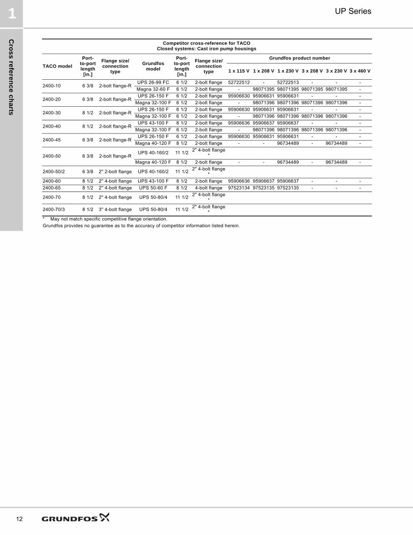
Competitor cross-reference for TACOClosed systems: Cast iron pump housings
TACO model
Port-to-port length
[in.]
Flange size/connection
type
Grundfos model
Port-to-port length
[in.]
Flange size/connection
type
Grundfos product number
1 x 115 V 1 x 208 V 1 x 230 V 3 x 208 V 3 x 230 V 3 x 460 V
* May not match specific competitive flange orientation.
Grundfos provides no guarantee as to the accuracy of competitor information listed herein.
Cro
ss
refe
ren
ce
ch
arts
UP Series1
12
2400-10 6 3/8 2-bolt flange-RUPS 26-99 FC 6 1/2 2-bolt flange 52722512 - 52722513 - - -
Magna 32-60 F 6 1/2 2-bolt flange - 98071395 98071395 98071395 98071395 -
2400-20 6 3/8 2-bolt flange-RUPS 26-150 F 6 1/2 2-bolt flange 95906630 95906631 95906631 - - -
Magna 32-100 F 6 1/2 2-bolt flange - 98071396 98071396 98071396 98071396 -
2400-30 8 1/2 2-bolt flange-RUPS 26-150 F 6 1/2 2-bolt flange 95906630 95906631 95906631 - - -
Magna 32-100 F 6 1/2 2-bolt flange - 98071396 98071396 98071396 98071396 -
2400-40 8 1/2 2-bolt flange-RUPS 43-100 F 8 1/2 2-bolt flange 95906636 95906637 95906637 - - -
Magna 32-100 F 6 1/2 2-bolt flange - 98071396 98071396 98071396 98071396 -
2400-45 6 3/8 2-bolt flange-RUPS 26-150 F 6 1/2 2-bolt flange 95906630 95906631 95906631 - - -
Magna 40-120 F 8 1/2 2-bolt flange - - 96734489 - 96734489 -
2400-50 6 3/8 2-bolt flange-RUPS 40-160/2 11 1/2
2" 4-bolt flange*
Magna 40-120 F 8 1/2 2-bolt flange - - 96734489 - 96734489 -
2400-50/2 6 3/8 2" 2-bolt flange UPS 40-160/2 11 1/22" 4-bolt flange
*
2400-60 8 1/2 2" 4-bolt flange UPS 43-100 F 8 1/2 2-bolt flange 95906636 95906637 95906637 - - -
2400-65 8 1/2 2" 4-bolt flange UPS 50-60 F 8 1/2 4-bolt flange 97523134 97523135 97523135 - - -
2400-70 8 1/2 2" 4-bolt flange UPS 50-80/4 11 1/22" 4-bolt flange
*
2400-70/3 8 1/2 3" 4-bolt flange UPS 50-80/4 11 1/22" 4-bolt flange
*
Competitor cross-reference for TACOClosed systems: Cast iron pump housings
TACO model
Port-to-port length
[in.]
Flange size/connection
type
Grundfos model
Port-to-port length
[in.]
Flange size/connection
type
Grundfos product number
1 x 115 V 1 x 208 V 1 x 230 V 3 x 208 V 3 x 230 V 3 x 460 V
* May not match specific competitive flange orientation.
Grundfos provides no guarantee as to the accuracy of competitor information listed herein.
Cro
ss
re
fere
nc
e c
ha
rts
UP Series 1
13
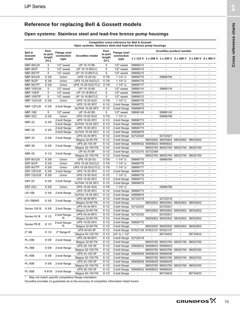
Reference for replacing Bell & Gossett models
Open systems: Stainless steel and lead-free bronze pump housings
Competitor cross-reference for Bell & GossettOpen systems: Stainless steel and lead-free bronze pump housings
Bell & Gossett model
Port-to-port length
[in.]
Flange size/connection
typeGrundfos model
Port-to-port length
[in.]
Flange size/connection
type
Grundfos product number
1 x 115 V 1 x 208 V 1 x 230 V 3 x 208 V 3 x 230 V 3 x 460 V
NBF-8S/LW 5 1/2" sweat UP 15-10 B5 5 1/2" sweat 59896213 - - - - -
NBF-8S/P 5 1/2" sweat UP 15-10 B5/LC 5 1/2" sweat 59896214 - - - - -
NBF-8S/TP 5 1/2" sweat UP 15-10 B5/TLC 5 1/2" sweat 59896215 - - - - -
NBF-9U/LW 6 3/8 Union UPS 15-29 SU 5 7/8 1 1/4" U 59896775 - 59896784 - - -
NBF-9U/P 6 3/8 Union UPS 15-29 SUC/LC 5 7/8 1 1/4" U 59896776 - - - - -
NBF-9U/TP 6 3/8 Union UPS 15-29 SUC/TLC 5 7/8 1 1/4" U 59896777 - - - - -
NBF-10S/LW 5 1/2" sweat UP 15-18 B5 5 1/2" sweat 59896114 - 59896118 - - -
NBF-10S/P 5 1/2" sweat UP 15-18 B5/LC 5 1/2" sweat 59896211 - - - - -
NBF-10S/TP 5 1/2" sweat UP 15-18 B5/TLC 5 1/2" sweat 59896212 - - - - -
NBF-12U/LW 6 3/8 Union UPS 15-35 SUC 5 7/8 1 1/4" U 59896778 - - - - -
NBF-12F/LW 6 3/8 2-bolt flangeUPS 15-35 SFC 6 1/2 2-bolt flange 59896772 - - - - -
ALPHA 15-55 SFC 6 1/2 2-bolt flange 59896879 - - - - -
NBF-18S 5 1/2" sweat UP 15-42 B5 5 1/2" sweat 59896145 - 59896142 - - -
NBF-22U 6 3/8 Union UPS 15-55 SUC 5 7/8 1 1/4" U - - 59896786 - - -
NBF-22 6 3/82-bolt flange UPS 15-55 SFC 6 1/2 2-bolt flange 59896773 - - - - -
2-bolt flange ALPHA 15-55 SFC 6 1/2 2-bolt flange 59896879 - - - - -
NBF-25 6 3/82-bolt flange UPS 15-55 SFC 6 1/2 2-bolt flange 59896773 - - - - -
2-bolt flange ALPHA 15-55 SFC 6 1/2 2-bolt flange 59896879 - - - - -
NBF-33 6 3/8 2-bolt flangeUPS 43-44 BFC 8 1/2 2-bolt flange 52722520 - 52722521 - - -
Magna 32-60 FN 6 1/2 2-bolt flange - 98052802 98052802 98052802 98052802 -
NBF-36 6 3/8 2-bolt flangeUPS 26-150 SF 6 1/2 2-bolt flange 95906632 95906633 95906633 - - -
Magna 32-100 FN 6 1/2 2-bolt flange - 98052760 98052760 98052760 98052760 -
NBF-45 8 1/2 2-bolt flangeUP 43-75 BF 8 1/2 2-bolt flange 52722370 52722369 - - - -
Magna 32-100 FN 6 1/2 2-bolt flange - 98052760 98052760 98052760 98052760 -
SSF-9U/LW 6 3/8 Union UPS 15-29 SU 5 7/8 1 1/4" U 59896775 - 59896784 - - -
SSF-9U/P 6 3/8 Union UPS 15-29 SUC/LC 5 7/8 1 1/4" U 59896776 - - - - -
SSF-9U/TP 6 3/8 Union UPS 15-29 SUC/TLC 5 7/8 1 1/4" U 59896777 - - - - -
SSF-12F/LW 6 3/8 2-bolt flange UPS 15-35 SFC 6 1/2 2-bolt flange 59896772 - - - - -
SSF-12U/LW 6 3/8 Union UPS 15-35 SUC 6 1/2 1 1/4" U 59896778 - - - - -
SSF-22 6 3/8 2-bolt flangeUPS 15-55 SFC 6 1/2 2-bolt flange 59896773 - - - - -
ALPHA 15-55 SFC 6 1/2 2-bolt flange 59896879 - - - - -
SSF-22U 6 3/8 Union UPS 15-55 SUC 5 7/8 1 1/4" U - - 59896786
LR-15B 6 3/8 2-bolt flangeUPS 15-55 SFC 6 1/2 2-bolt flange 59896773 - - - - -
ALPHA 15-55 SFC 6 1/2 2-bolt flange 59896879 - - - - -
LR-15BWR 6 3/8 2-bolt flangeUPS 26-99 BFC 8 1/2 2-bolt flange 52722518 - 52722519 - - -
Magna 32-60 FN 6 1/2 2-bolt flange - 98052802 98052802 98052802 98052802 -
Series 100 B 6 3/8 2-bolt flangeUPS 43-44 BFC 8 1/2 2-bolt flange 52722520 - 52722521 - - -
Magna 32-60 FN 6 1/2 2-bolt flange - 98052802 98052802 98052802 98052802 -
Series HV B 8 1/22-bolt flange-
RUPS 43-44 BFC 8 1/2 2-bolt flange 52722520 - 52722521 - - -
Magna 32-60 FN 6 1/2 2-bolt flange - 98052802 98052802 98052802 98052802 -
Series PR B 8 1/22-bolt flange-
RUPS 15-55 SFC 6 1/2 2-bolt flange 59896773 - - - - -
Magna 32-60 FN 6 1/2 2-bolt flange - 98052802 98052802 98052802 98052802 -
2" AB 8 1/2 2" flange-RUPS 50-60 SF 8 1/2 4-bolt flange 97523136 97523137 97523137 - - -
Magna 40-120 FN 8 1/2 3/4" to 1 1/2" - - 96734633 - 96734633 -
PL-30B 8 5/8 2-bolt flangeUPS 26-99 BFC 6 1/2 2-bolt flange 52722518 - - - - -
Magna 32-60 FN 6 1/2 2-bolt flange - 98052760 98052760 98052760 98052760 -
PL-36B 8 5/8 2-bolt flangeUPS 26-150 SF 6 1/2 2-bolt flange 95906632 95906633 95906633 - - -
Magna 32-100 FN 6 1/2 2-bolt flange - 98052760 98052760 98052760 98052760 -
PL-45B 9 3/8 2-bolt flangeUPS 43-100 SF 8 1/2 2-bolt flange 95906638 95906639 95906639 - - -
Magna 32-100 FN 6 1/2 2-bolt flange - 98052760 98052760 98052760 98052760 -
PL-50B 9 3/8 2-bolt flangeUPS 43-100 SF 8 1/2 2-bolt flange 95906638 95906639 95906639 - - -
Magna 32-100 FN 6 1/2 2-bolt flange - 98052760 98052760 98052760 98052760 -
PL-55B 9 9/16 2-bolt flangeUPS 26-150 SF 6 1/2 2-bolt flange 95906632 95906633 95906633 - - -
Magna 40-120 FN 8 1/2 2-bolt flange - - 96734633 - 96734633 -
* May not match specific competitive flange orientation.
Grundfos provides no guarantee as to the accuracy of competitor information listed herein.

Cro
ss
refe
ren
ce
ch
arts
UP Series1
14
PL-75B 9 15/16 2" UPS 50-60 SF 8 1/2 4-bolt flange 97523136 97523137 97523137 - - -
Magna 40-120 FN 8 1/2 2-bolt flange - - 96734633 - 96734633 -
Competitor cross-reference for Bell & GossettOpen systems: Stainless steel and lead-free bronze pump housings
Bell & Gossett model
Port-to-port length
[in.]
Flange size/connection
typeGrundfos model
Port-to-port length
[in.]
Flange size/connection
type
Grundfos product number
1 x 115 V 1 x 208 V 1 x 230 V 3 x 208 V 3 x 230 V 3 x 460 V
* May not match specific competitive flange orientation.
Grundfos provides no guarantee as to the accuracy of competitor information listed herein.

Cro
ss
re
fere
nc
e c
ha
rts
UP Series 1
15
Closed systems: Cast iron pump housings
Competitor cross-reference for Bell & GossettClosed systems: Cast iron pump housings
Bell & Gossett model
Port-to-port length
[in.]
Flange size/connection
typeGrundfos model
Port-to-port length
[in.]
Flange size/connection
type
Grundfos product number
1 x 115 V 1 x 208 V 1 x 230 V 3 x 208 V 3 x 230 V 3 x 460 V
NRF-9F/LW
6 3/8 2-bolt flange-R
UP 15-42 FR 6 1/2 2-bolt flange-R 59896167 - 59896274 - - -
UPS 15-58 FRC 6 1/2 2-bolt flange-R 59896343 - - - - -
ALPHA 15-55 FR 6 1/2 2-bolt flange-R 59896878 - - - - -
NRF-22 6 3/8 2-bolt flange-R
UP 15-42 FR 6 1/2 2-bolt flange-R 59896167 - 59896274 - - -
UPS 15-42 FR 6 1/2 2-bolt flange-R 59896167 - 59896274 - - -
UPS 15-58 FRC 6 1/2 2-bolt flange-R 59896343 - - - - -
ALPHA 15-55 FR 6 1/2 2-bolt flange-R 59896878 - - - - -
NRF-25 6 3/8 2-bolt flangeUPS15-58 FC 6 1/2 2-bolt flange 59896341 - - - - -
ALPHA 15-55 FC 6 1/2 2-bolt flange 59896877 - - - - -
NRF-33 6 3/8 2-bolt flangeUPS 43-44 FC 8 1/2 2-bolt flange 52722514 - 52722515 - - -
Magna 32-60 F 6 1/2 2-bolt flange - 98071395 98071395 98071395 98071395 -
NRF-36 6 3/8 2-bolt flange
UPS 26-150 F 6 1/2 2-bolt flange 95906630 95906631 95906631 - - -
UPS 43-100 F 8 1/2 2-bolt flange 95906636 95906637 95906637 - - -
Magna 32-100 F 6 1/2 2-bolt flange - 98071396 98071396 98071396 98071396 -
NRF-45 8 1/2 2-bolt flange
UP 43-75 FC 8 1/2 2-bolt flange 52722373 - 52722372 - - -
UPS 43-100 F 8 1/2 2-bolt flange 95906636 95906637 95906637 - - -
Magna 32-100 F 6 1/2 2-bolt flange - 98071396 98071396 98071396 98071396 -
LR-20WR 6 3/8 2-bolt flangeUPS 43-44 FC 8 1/2 2-bolt flange 52722514 - 52722515 - - -
Magna 32-60 F 6 1/2 2-bolt flange - 98071395 98071395 98071395 98071395 -
Series 100 6 3/8 2-bolt flangeUPS 43-44 FC 8 1/2 2-bolt flange 52722514 - 52722515 - - -
Magna 32-60 F 6 1/2 2-bolt flange - 98071395 98071395 98071395 98071395 -
Series HV 8 1/2 2-bolt flange-RUPS 43-44 FC 8 1/2 2-bolt flange 52722514 - 52722515 - - -
Magna 32-60 F 6 1/2 2-bolt flange - 98071395 98071395 98071395 98071395 -
Series PR 8 1/2 2-bolt flangeUPS 26-99 FC 6 1/2 2-bolt flange 52722512 - 52722513 - - -
Magna 32-60 F 6 1/2 2-bolt flange - 98071395 98071395 98071395 98071395 -
2" 8 1/2 2" flange-RUPS 50-44 FC 8 1/2 2" flange 52722557 - 52722558 - - -
Magna 40-120 F 8 1/2 2-bolt flange - - 96734489 - 96734489 -
PL-30 8 5/8 2-bolt flangeUPS 26-99 FC 6 1/2 2-bolt flange 52722512 - 52722513 - - -
Magna 32-60 F 6 1/2 2-bolt flange - 98071395 98071395 98071395 98071395 -
PL-36 8 5/8 2-bolt flangeUPS 26-150 F 6 1/2 2-bolt flange 95906630 95906631 95906631 - - -
Magna 32-100 F 6 1/2 2-bolt flange - 98071396 98071396 98071396 98071396 -
PL-45 9 1/8 2-bolt flangeUPS 43-100 F 8 1/2 2-bolt flange 95906636 95906637 95906637 - - -
Magna 32-100 F 6 1/2 2-bolt flange - 98071396 98071396 98071396 98071396 -
PL-50 9 1/8 2-bolt flangeUPS 43-100 F 8 1/2 2-bolt flange 95906636 95906637 95906637 - - -
Magna 32-100 F 6 1/2 2-bolt flange - 98071396 98071396 98071396 98071396 -
PL-55 9 9/16 2-bolt flangeUPS 26-150 F 6 1/2 2-bolt flange 95906630 95906631 95906631 - - -
Magna 40-120 F 8 1/2 2-bolt flange - - 96734489 - 96734489 -
PL-75 9 15/16 2" UPS 50-60 F 8 1/2 4-bolt flange 97523134 97523135 97523135 - - -
Magna 40-120 F 8 1/2 2-bolt flange - - 96734489 - 96734489 -
* May not match specific competitive flange orientation.
Grundfos provides no guarantee as to the accuracy of competitor information listed herein.
Cro
ss
refe
ren
ce
ch
arts
UP Series1
16
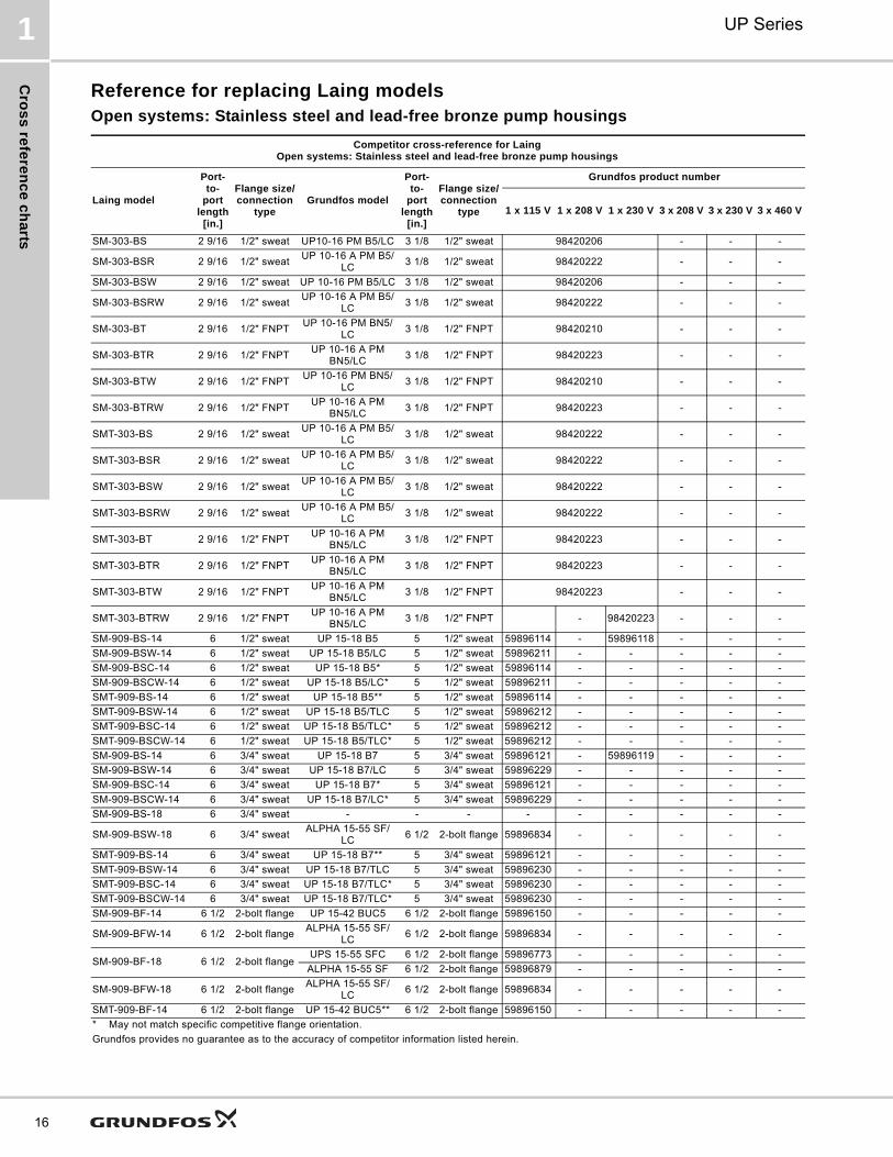
Reference for replacing Laing modelsOpen systems: Stainless steel and lead-free bronze pump housings
Competitor cross-reference for LaingOpen systems: Stainless steel and lead-free bronze pump housings
Laing model
Port-to-
port length
[in.]
Flange size/connection
typeGrundfos model
Port-to-
port length
[in.]
Flange size/connection
type
Grundfos product number
1 x 115 V 1 x 208 V 1 x 230 V 3 x 208 V 3 x 230 V 3 x 460 V
SM-303-BS 2 9/16 1/2" sweat UP10-16 PM B5/LC 3 1/8 1/2" sweat 98420206 - - -
SM-303-BSR 2 9/16 1/2" sweatUP 10-16 A PM B5/
LC3 1/8 1/2" sweat 98420222 - - -
SM-303-BSW 2 9/16 1/2" sweat UP 10-16 PM B5/LC 3 1/8 1/2" sweat 98420206 - - -
SM-303-BSRW 2 9/16 1/2" sweatUP 10-16 A PM B5/
LC3 1/8 1/2" sweat 98420222 - - -
SM-303-BT 2 9/16 1/2" FNPTUP 10-16 PM BN5/
LC3 1/8 1/2" FNPT 98420210 - - -
SM-303-BTR 2 9/16 1/2" FNPTUP 10-16 A PM
BN5/LC3 1/8 1/2" FNPT 98420223 - - -
SM-303-BTW 2 9/16 1/2" FNPTUP 10-16 PM BN5/
LC3 1/8 1/2" FNPT 98420210 - - -
SM-303-BTRW 2 9/16 1/2" FNPTUP 10-16 A PM
BN5/LC3 1/8 1/2" FNPT 98420223 - - -
SMT-303-BS 2 9/16 1/2" sweatUP 10-16 A PM B5/
LC3 1/8 1/2" sweat 98420222 - - -
SMT-303-BSR 2 9/16 1/2" sweatUP 10-16 A PM B5/
LC3 1/8 1/2" sweat 98420222 - - -
SMT-303-BSW 2 9/16 1/2" sweatUP 10-16 A PM B5/
LC3 1/8 1/2" sweat 98420222 - - -
SMT-303-BSRW 2 9/16 1/2" sweatUP 10-16 A PM B5/
LC3 1/8 1/2" sweat 98420222 - - -
SMT-303-BT 2 9/16 1/2" FNPTUP 10-16 A PM
BN5/LC3 1/8 1/2" FNPT 98420223 - - -
SMT-303-BTR 2 9/16 1/2" FNPTUP 10-16 A PM
BN5/LC3 1/8 1/2" FNPT 98420223 - - -
SMT-303-BTW 2 9/16 1/2" FNPTUP 10-16 A PM
BN5/LC3 1/8 1/2" FNPT 98420223 - - -
SMT-303-BTRW 2 9/16 1/2" FNPTUP 10-16 A PM
BN5/LC3 1/8 1/2" FNPT - 98420223 - - -
SM-909-BS-14 6 1/2" sweat UP 15-18 B5 5 1/2" sweat 59896114 - 59896118 - - -
SM-909-BSW-14 6 1/2" sweat UP 15-18 B5/LC 5 1/2" sweat 59896211 - - - - -
SM-909-BSC-14 6 1/2" sweat UP 15-18 B5* 5 1/2" sweat 59896114 - - - - -
SM-909-BSCW-14 6 1/2" sweat UP 15-18 B5/LC* 5 1/2" sweat 59896211 - - - - -
SMT-909-BS-14 6 1/2" sweat UP 15-18 B5** 5 1/2" sweat 59896114 - - - - -
SMT-909-BSW-14 6 1/2" sweat UP 15-18 B5/TLC 5 1/2" sweat 59896212 - - - - -
SMT-909-BSC-14 6 1/2" sweat UP 15-18 B5/TLC* 5 1/2" sweat 59896212 - - - - -
SMT-909-BSCW-14 6 1/2" sweat UP 15-18 B5/TLC* 5 1/2" sweat 59896212 - - - - -
SM-909-BS-14 6 3/4" sweat UP 15-18 B7 5 3/4" sweat 59896121 - 59896119 - - -
SM-909-BSW-14 6 3/4" sweat UP 15-18 B7/LC 5 3/4" sweat 59896229 - - - - -
SM-909-BSC-14 6 3/4" sweat UP 15-18 B7* 5 3/4" sweat 59896121 - - - - -
SM-909-BSCW-14 6 3/4" sweat UP 15-18 B7/LC* 5 3/4" sweat 59896229 - - - - -
SM-909-BS-18 6 3/4" sweat - - - - - - - - -
SM-909-BSW-18 6 3/4" sweatALPHA 15-55 SF/
LC6 1/2 2-bolt flange 59896834 - - - - -
SMT-909-BS-14 6 3/4" sweat UP 15-18 B7** 5 3/4" sweat 59896121 - - - - -
SMT-909-BSW-14 6 3/4" sweat UP 15-18 B7/TLC 5 3/4" sweat 59896230 - - - - -
SMT-909-BSC-14 6 3/4" sweat UP 15-18 B7/TLC* 5 3/4" sweat 59896230 - - - - -
SMT-909-BSCW-14 6 3/4" sweat UP 15-18 B7/TLC* 5 3/4" sweat 59896230 - - - - -
SM-909-BF-14 6 1/2 2-bolt flange UP 15-42 BUC5 6 1/2 2-bolt flange 59896150 - - - - -
SM-909-BFW-14 6 1/2 2-bolt flangeALPHA 15-55 SF/
LC6 1/2 2-bolt flange 59896834 - - - - -
SM-909-BF-18 6 1/2 2-bolt flangeUPS 15-55 SFC 6 1/2 2-bolt flange 59896773 - - - - -
ALPHA 15-55 SF 6 1/2 2-bolt flange 59896879 - - - - -
SM-909-BFW-18 6 1/2 2-bolt flangeALPHA 15-55 SF/
LC6 1/2 2-bolt flange 59896834 - - - - -
SMT-909-BF-14 6 1/2 2-bolt flange UP 15-42 BUC5** 6 1/2 2-bolt flange 59896150 - - - - -
* May not match specific competitive flange orientation.
Grundfos provides no guarantee as to the accuracy of competitor information listed herein.
Cro
ss
re
fere
nc
e c
ha
rts
UP Series 1
17
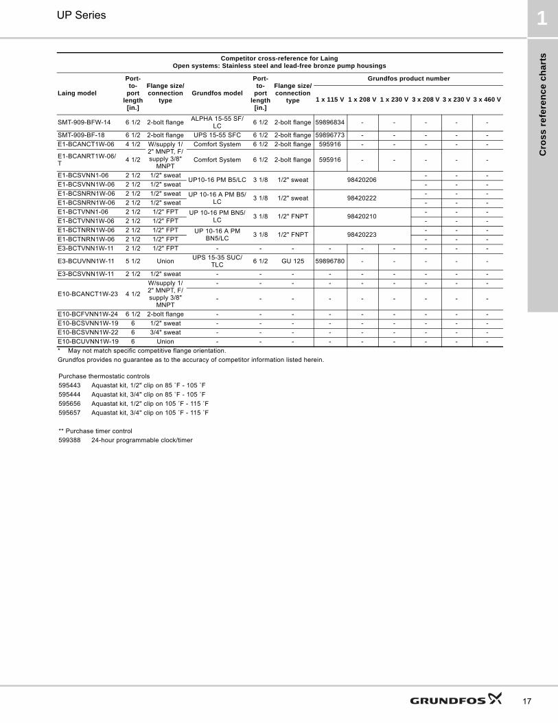
SMT-909-BFW-14 6 1/2 2-bolt flangeALPHA 15-55 SF/
LC6 1/2 2-bolt flange 59896834 - - - - -
SMT-909-BF-18 6 1/2 2-bolt flange UPS 15-55 SFC 6 1/2 2-bolt flange 59896773 - - - - -
E1-BCANCT1W-06 4 1/2 W/supply 1/2" MNPT, F/supply 3/8"
MNPT
Comfort System 6 1/2 2-bolt flange 595916 - - - - -
E1-BCANRT1W-06/T
4 1/2 Comfort System 6 1/2 2-bolt flange 595916 - - - - -
E1-BCSVNN1-06 2 1/2 1/2" sweatUP10-16 PM B5/LC 3 1/8 1/2" sweat 98420206
- - -
E1-BCSVNN1W-06 2 1/2 1/2" sweat - - -
E1-BCSNRN1W-06 2 1/2 1/2" sweat UP 10-16 A PM B5/LC
3 1/8 1/2" sweat 98420222- - -
E1-BCSNRN1W-06 2 1/2 1/2" sweat - - -
E1-BCTVNN1-06 2 1/2 1/2" FPT UP 10-16 PM BN5/LC
3 1/8 1/2" FNPT 98420210- - -
E1-BCTVNN1W-06 2 1/2 1/2" FPT - - -
E1-BCTNRN1W-06 2 1/2 1/2" FPT UP 10-16 A PM BN5/LC
3 1/8 1/2" FNPT 98420223- - -
E1-BCTNRN1W-06 2 1/2 1/2" FPT - - -
E3-BCTVNN1W-11 2 1/2 1/2" FPT - - - - - - - - -
E3-BCUVNN1W-11 5 1/2 UnionUPS 15-35 SUC/
TLC6 1/2 GU 125 59896780 - - - - -
E3-BCSVNN1W-11 2 1/2 1/2" sweat - - - - - - - - -
E10-BCANCT1W-23 4 1/2
W/supply 1/2" MNPT, F/supply 3/8"
MNPT
- - - - - - - - -
- - - - - - - - -
E10-BCFVNN1W-24 6 1/2 2-bolt flange - - - - - - - - -
E10-BCSVNN1W-19 6 1/2" sweat - - - - - - - - -
E10-BCSVNN1W-22 6 3/4" sweat - - - - - - - - -
E10-BCUVNN1W-19 6 Union - - - - - - - - -
Competitor cross-reference for LaingOpen systems: Stainless steel and lead-free bronze pump housings
Laing model
Port-to-
port length
[in.]
Flange size/connection
typeGrundfos model
Port-to-
port length
[in.]
Flange size/connection
type
Grundfos product number
1 x 115 V 1 x 208 V 1 x 230 V 3 x 208 V 3 x 230 V 3 x 460 V
* May not match specific competitive flange orientation.
Grundfos provides no guarantee as to the accuracy of competitor information listed herein.
Purchase thermostatic controls
595443 Aquastat kit, 1/2" clip on 85 ˚F - 105 ˚F
595444 Aquastat kit, 3/4" clip on 85 ˚F - 105 ˚F
595656 Aquastat kit, 1/2" clip on 105 ˚F - 115 ˚F
595657 Aquastat kit, 3/4" clip on 105 ˚F - 115 ˚F
** Purchase timer control
599388 24-hour programmable clock/timer

Cro
ss
refe
ren
ce
ch
arts
UP Series1
18
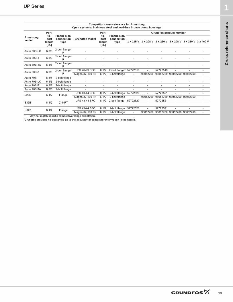
Reference for replacing Armstrong models
Open systems: Stainless steel and lead-free bronze pump housings
Competitor cross-reference for ArmstrongOpen systems: Stainless steel and lead-free bronze pump housings
Armstrong model
Port-to-
port length
[in.]
Flange size/connection
typeGrundfos model
Port-to-
port length
[in.]
Flange size/connection
type
Grundfos product number
1 x 115 V 1 x 208 V 1 x 230 V 3 x 208 V 3 x 230 V 3 x 460 V
Astro 20B050S 5 1/2" sweat UP 15-10 B5 5 1/2" sweat 59896213 - - - - -
Astro 20B050S-LC
5 1/2" sweat UP 15-10 B5/LC 5 1/2" sweat 59896214 - - - - -
Astro 20B050S-T
5 1/2" sweat UP 15-10 B5/TLC 5 1/2" sweat 59896215 - - - - -
Astro 20B050S-TA
5 1/2" sweat - - - - - - - - -
Astro 20B075S 5 3/4" sweat UP 15-10 B7 6 3/8 3/4" sweat 59896226 - - - - -
Astro 20B075S-LC
5 3/4" sweat UP 15-10 B7/LC 6 3/8 3/4" sweat 59896209 - - - - -
Astro 20B075S-T
5 3/4" sweat UP 15-10 B7/TLC 6 3/8 3/4" sweat 59896210 - - - - -
Astro 20B075S-TA
5 3/4" sweat - - - - - - - - -
Astro 20BF-LC 6 3/8 2-bolt flange - - - - - - - - -
Astro 20BF-T 6 3/8 2-bolt flange - - - - - - - - -
Astro 20BF-TA 6 3/8 2-bolt flange - - - - - - - - -
Astro 20BU 5 1 1/4" union UP 15-29 SU 5 7/8 1 1/4" union 59896775 - 59896784 - - -
Astro 20BU-T 5 1 1/4" union UP 15-29 SU/TLC 5 7/8 1 1/4" union 59896777 - - - - -
Astro 20BU-TA 5 1 1/4" union - - - - - - - - -
Astro 225BS 5 1/2" sweat UPS 15-35 SFC 6 1/2 2-bolt flange* 59896772 - - - - -
Astro 225BS 5 3/4" sweat UPS 15-35 SFC 6 1/2 2-bolt flange* 59896772 - - - - -
Astro 220SSU 6 1 1/4" union UPS 15-35 SUC 5 7/8 1 1/4" union 59896778 - - - - -
Astro 225SSU 6 1 1/4" union UPS 15-35 SUC 5 7/8 1 1/4" union 59896778 - - - - -
Astro 230SSU 6 3/8 1 1/4" union UPS 15-55 SUC 6 1/2 2-bolt flange - - 59896786 -
Astro 250SSU 6 3/8 1 1/4" union - - - - - - - - -
Astro 25B050S 5 1/2" sweat UP 15-18 B5 5 1/2" sweat 59896114 - 59896118 - - -
Astro 25B050S-LC
5 1/2" sweat UP 15-18 B5/LC 5 1/2" sweat 59896211 - - - - -
Astro 25B050S-T
5 1/2" sweat UP 15-18 B5/TLC 5 1/2" sweat 59896212 - - - - -
Astro 25B050S-TA
5 1/2" sweat - - - - - - - - -
Astro 25B075S 5 3/4" sweat UP 15-18 B7 6 3/8 3/4" sweat 59896121 - 59896119 - - -
Astro 25B075S-LC
5 3/4" sweat UP 15-18 B7/LC 6 3/8 3/4" sweat 59896229 - - - - -
Astro 25B075S-T
5 3/4" sweat UP 15-18 B7/TLC 6 3/8 3/4" sweat 59896230 - - - - -
Astro 25B075S-TA
5 3/4" sweat - - - - - - - - -
Astro 25BU 6 1 1/4" union UPS 15-29 SU 5 7/8 1 1/4" union 59896775 - 59896784 - - -
Astro 25BU-LC 6 1 1/4" union UPS 15-29 SU/LC 5 7/8 1 1/4" union 59896776 - - - - -
Astro 25BU-T 6 1 1/4" unionUPS 15-29 SUC/
TLC5 7/8 1 1/4" union 59896777 - - - - -
Astro 25BU-TA 6 1 1/4" union - - - - - - - - -
Astro 30B 6 3/82-bolt flange-
RUPS 15-55 SFC 6 1/2 2-bolt flange* 59896773 - - - - -
Astro 30B-LC 6 3/82-bolt flange-
RALPHA 15-55 SF/
LC6 1/2 2-bolt flange* 59896834 - - - - -
Astro 30B-T 6 3/82-bolt flange-
R- - - - - - - - -
Astro 30B-TA 6 3/82-bolt flange-
R- - - - - - - - -
Astro 30B-3 6 3/82-bolt flange-
RUPS 15-55 SFC 6 1/2 2-bolt flange* 59896773 - - - - -
ALPHA 15-55 SF 6 1/2 2-bolt flange* 59896879 - - - - -
Astro 50B 6 3/82-bolt flange-
RUPS 26-99 BFC 6 1/2 2-bolt flange* 52722518 - 52722519 -
Magna 32-100 FN 6 1/2 2-bolt flange - 98052760 98052760 98052760 98052760 -
* May not match specific competitive flange orientation.
Grundfos provides no guarantee as to the accuracy of competitor information listed herein.
Cro
ss
re
fere
nc
e c
ha
rts
UP Series 1
19
Astro 50B-LC 6 3/82-bolt flange-
R- - - - - - - - -
Astro 50B-T 6 3/82-bolt flange-
R- - - - - - - - -
Astro 50B-TA 6 3/82-bolt flange-
R- - - - - - - - -
Astro 50B-3 6 3/82-bolt flange-
RUPS 26-99 BFC 6 1/2 2-bolt flange* 52722518 - 52722519 - - -
Magna 32-100 FN 6 1/2 2-bolt flange - 98052760 98052760 98052760 98052760 -
Astro 70B 6 3/8 2-bolt flange - - - - - - - - -
Astro 70B-LC 6 3/8 2-bolt flange - - - - - - - - -
Astro 70B-T 6 3/8 2-bolt flange - - - - - - - - -
Astro 70B-TA 6 3/8 2-bolt flange - - - - - - - - -
S25B 6 1/2 FlangeUPS 43-44 BFC 8 1/2 2-bolt flange 52722520 - 52722521 - - -
Magna 32-100 FN 6 1/2 2-bolt flange - 98052760 98052760 98052760 98052760 -
S35B 8 1/2 2" NPTUPS 43-44 BFC 8 1/2 2-bolt flange* 52722520 - 52722521 - - -
H32B 8 1/2 FlangeUPS 43-44 BFC 8 1/2 2-bolt flange 52722520 - 52722521 - - -
Magna 32-100 FN 6 1/2 2-bolt flange - 98052760 98052760 98052760 98052760 -
Competitor cross-reference for ArmstrongOpen systems: Stainless steel and lead-free bronze pump housings
Armstrong model
Port-to-
port length
[in.]
Flange size/connection
typeGrundfos model
Port-to-
port length
[in.]
Flange size/connection
type
Grundfos product number
1 x 115 V 1 x 208 V 1 x 230 V 3 x 208 V 3 x 230 V 3 x 460 V
* May not match specific competitive flange orientation.
Grundfos provides no guarantee as to the accuracy of competitor information listed herein.

Cro
ss
refe
ren
ce
ch
arts
UP Series1
20
Closed systems: Cast iron pump housings
Competitor cross-reference for ArmstrongClosed systems: Cast iron pump housings
Armstrong model
Port-to-
port length
[in.]
Flange size/connection
type
Grundfos model
Port-to-
port length
[in.]
Flange size/connection
type
Grundfos product number
1 x 115 V 1 x 208 V 1 x 230 V 3 x 208 V 3 x 230 V 3 x 460 V
Astro 230CI 6 3/8 2-bolt flangeUPS 15-58 FC 6 1/2 2-bolt flange 59896341 - - - - -
ALPHA 15-55 FC
6 1/2 2-bolt flange 59896877 - - - - -
Astro 230CI-R 6 3/8 2-bolt flange-RUPS 15-58 FRC 6 1/2 2-bolt flange 59896343 - - - - -
ALPHA 15-55 FRC
6 1/2 2-bolt flange 59896878 - - - - -
Astro 250CI 6 3/8 2-bolt flangeUPS 26-99 FC 6 1/2 2-bolt flange 52722512 - 52722513
Magna 32-100 F 6 1/2 2-bolt flange - 98071396 98071396 98071396 98071396 -
Astro 250CI-R 6 3/8 2-bolt flange-R - - - - - - - - -
Astro 20F 6 3/8 2-bolt flange-R - - - - - - - - -
Astro 30 6 3/8 2-bolt flange-R
UPS 15-58 FRC 6 1/22-bolt flange-
R59896343 - - - - -
ALPHA 15-55 FRC
6 1/2 2-bolt flange 59896878 - - - - -
UP 15-42 FR 6 1/22-bolt flange-
R59896167 - 59896274
Astro 30-3 6 3/8 2-bolt flangeUPS 15-58 FC 6 1/2 2-bolt flange 59896341 - - - - -
ALPHA 15-55 FC
6 1/2 2-bolt flange 59896877 - - - - -
Astro 50 6 3/8 2-bolt flange-R UPS 26-99 FC 6 1/2 2-bolt flange* 52722512 - 52722513 - - -
Astro 50-3 6 3/8 2-bolt flange UPS 26-99 FC 6 1/2 2-bolt flange 52722512 - 52722513 - - -
Astro 70 6 3/8 2-bolt flange - - - - - - - - -
S25 6 1/2 FlangeUPS 26-99 FC 6 1/2 2-bolt flange 52722512 - 52722513 - - -
Magna 32-100 F 6 1/2 2-bolt flange - 98071396 98071396 98071396 98071396 -
H32 8 9/16 2-bolt flange-RUPS 43-44 FC 8 1/2 2-bolt flange* 52722514 - 52722515 - - -
Magna 32-100 F 6 1/2 2-bolt flange - 98071396 98071396 98071396 98071396 -
S35 8 1/2 2" flange-R UPS 50-44 F 8 1/2 2" 4-bolt flange
- - - - - -
* May not match specific competitive flange orientation.
Grundfos provides no guarantee as to the accuracy of competitor information listed herein.
Cro
ss
re
fere
nc
e c
ha
rts
UP Series 1
21
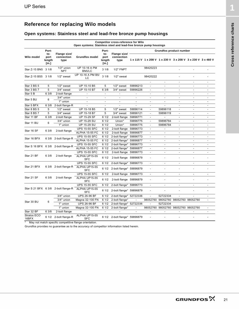
Reference for replacing Wilo models
Open systems: Stainless steel and lead-free bronze pump housings
Competitor cross-reference for WiloOpen systems: Stainless steel and lead-free bronze pump housings
Wilo model
Port-to-
port length
[in.]
Flange size/connection
typeGrundfos model
Port-to-
port length
[in.]
Flange size/connection
type
Grundfos product number
1 x 115 V 1 x 208 V 1 x 230 V 3 x 208 V 3 x 230 V 3 x 460 V
Star Z-15 BN5 3 1/8 1/2" union
NPTUP 10-16 A PM
BN5/LC3 1/8 1/2" FNPT
98420223- - -
Star Z-15 BS5 3 1/8 1/2" sweatUP 10-16 A PM B5/
LC3 1/8 1/2" sweat 98420222 - - -
- - - - -
Star 3 BS 5 5 1/2" sweat UP 15-10 B5 5 1/2" sweat 59896213 - - - - -
Star 3 BS 7 5 3/4" sweat UP 15-10 B7 6 3/8 3/4" sweat 59896226 - - - - -
Star 5 B 6 3/8 2-bolt flange - - - - - - - - -
Star 5 BU 63/4" union - - - - - - - - -
1" union - - - - - - - - -
Star 5 BFX 6 3/8 2-bolt flange-R - - - - - - - - -
Star 8 BS 5 5 1/2" sweat UP 15-18 B5 5 1/2" sweat 59896114 - 59896118 - - -
Star 8 BS 7 5 3/4" sweat UP 15-18 B7 5 3/4" sweat 59896121 - 59896119 - - -
Star 11 BF 6 3/8 2-bolt flange UP 15-29 SF 6 1/2 2-bolt flange 59896771 - - - - -
Star 11 BU 63/4" union UP 15-29 SU 6 1/2 Union* 59896775 - 59896784 - - -
1" union UP 15-29 SU 6 1/2 Union* 59896775 - 59896784 - - -
Star 16 SF 6 3/8 2-bolt flangeUPS 15-55 SFC 6 1/2 2-bolt flange 59896773 - - - - -
ALPHA 15-55 FC 6 1/2 2-bolt flange 59896877 - - - - -
Star 16 BFX 6 3/8 2-bolt flange-RUPS 15-55 SFC 6 1/2 2-bolt flange* 59896773 - - - - -
ALPHA 15-55 FC 6 1/2 2-bolt flange* 59896877 - - - - -
Star S 16 BFX 6 3/8 2-bolt flange-RUPS 15-55 SFC 6 1/2 2-bolt flange* 59896773 - - - - -
ALPHA 15-55 FC 6 1/2 2-bolt flange* 59896877 - - - - -
Star 21 BF 6 3/8 2-bolt flangeUPS 15-55 SFC 6 1/2 2-bolt flange 59896773 - - - - -
ALPHA UP15-55 SFC
6 1/2 2-bolt flange 59896879 - - - - -
Star 21 BFX 6 3/8 2-bolt flange-RUPS 15-55 SFC 6 1/2 2-bolt flange* 59896773 - - - - -
ALPHA UP15-55 SFC
6 1/2 2-bolt flange* 59896879 - - - - -
Star 21 SF 6 3/8 2-bolt flangeUPS 15-55 SFC 6 1/2 2-bolt flange 59896773 - - - - -
ALPHA UP15-55 SFC
6 1/2 2-bolt flange 59896879 - - - - -
Star S 21 BFX 6 3/8 2-bolt flange-RUPS 15-55 SFC 6 1/2 2-bolt flange* 59896773 - - - - -
ALPHA UP15-55 SFC
6 1/2 2-bolt flange* 59896879 - - - - -
Star 30 BU 6
3/4" union UPS 26-96 BF 6 1/2 2-bolt flange* 52722336 - 52722334 - - -
3/4" union Magna 32-100 FN 6 1/2 2-bolt flange* - 98052760 98052760 98052760 98052760 -
1" union UPS 26-96 BF 6 1/2 2-bolt flange* 52722336 - 52722334
1" union Magna 32-100 FN 6 1/2 2-bolt flange* - 98052760 98052760 98052760 98052760 -
Star 32 BF 6 3/8 2-bolt flange - - - - - - - - -
Stratos ECO 16BFX
6 1/2 2-bolt flange-RALPHA UP15-55
SFC6 1/2 2-bolt flange* 59896879 - - - - -
* May not match specific competitive flange orientation.
Grundfos provides no guarantee as to the accuracy of competitor information listed herein.
Cro
ss
refe
ren
ce
ch
arts
UP Series1
22
Closed systems: Cast iron pump housings
Competitor cross-reference for WiloClosed systems: Cast iron pump housings
Wilo model
Port-to-
port length
[in.]
Flange size/connection
typeGrundfos model
Port-to-
port length
[in.]
Flange size/connection
type
Grundfos product number
1 x 115 V 1 x 208 V 1 x 230 V 3 x 208 V 3 x 230 V 3 x 460 V
Star 5 FX 6 3/8 2-bolt flange-R UP 15-10 FR 6 1/2 2-bolt flange-R 59896249 - - - - -
Star 16 F 6 3/8 2-bolt flange UP 15-10 F 6 1/2 2-bolt flange 59896248 - - - - -
Star 16 FX 6 3/8 2-bolt flange-RUPS 15-58 FRC 6 1/2 2-bolt flange-R 59896343 - - - - -
ALPHA 15-55 FRC
6 1/2 2-bolt flange-R 59896878 - - - -
Star S 16 F 6 3/8 2-bolt flangeUPS 15-58 FC 6 1/2 2-bolt flange 59896341 - - - - -
ALPHA 15-55 FC 6 1/2 2-bolt flange 59896877 - - - - -
Star S 16 FX 6 3/8 2-bolt flange-RUPS 15-58 FRC 6 1/2 2-bolt flange-R 59896343 - - - - -
ALPHA 15-55 FRC
6 1/2 2-bolt flange-R 59896878 - - - - -
Star 17 FX 8 1/2 2-bolt flange-R UPS 43-44 FC 8 1/2 2-bolt flange* 52722514 - 52722515 - - -
Star 21 F 6 3/8 2-bolt flangeALPHA UP15-55
FC6 1/2 2-bolt flange 59896877 - - - - -
Star 21 FX 6 3/8 2-bolt flange-RALPHA UP15-55
FRC6 1/2 2-bolt flange-R 59896878 - - - - -
Star S 21 F 6 3/8 2-bolt flangeALPHA UP15-55
FC6 1/2 2-bolt flange 59896877 - - - - -
Star S 21 FX 6 3/8 2-bolt flange-RALPHA UP15-55
FRC6 1/2 2-bolt flange-R 59896878 - - - - -
Star 30 F 6 1/2 2-bolt flangeUPS 26-99 FC 6 1/2 2-bolt flange 52722512 - 52722513 - - -
Magna 32-100 FN 6 1/2 2-bolt flange* - 98052760 98052760 98052760 98052760 -
Star 32 F 6 3/8 2-bolt flange UP 15-100 F 6 1/2 2-bolt flange 59896300 - - - - -
Stratos ECO 16F
6 1/2 2-bolt flangeALPHA UP15-55
FC6 1/2 2-bolt flange 59896877 - - - - -
Stratos ECO 16FX
6 1/2 2-bolt flange-RALPHA UP15-55
FRC6 1/2 2-bolt flange-R 59896878 - - - - -
* May not match specific competitive flange orientation.
Grundfos provides no guarantee as to the accuracy of competitor information listed herein.
Cro
ss
re
fere
nc
e c
ha
rts
UP Series 1
23
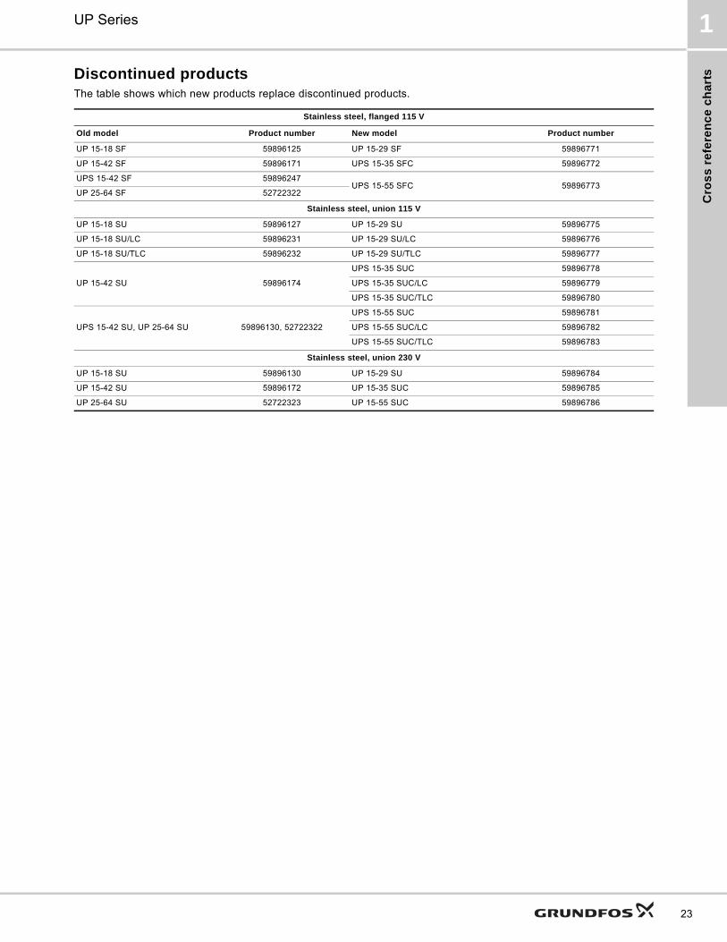
Discontinued productsThe table shows which new products replace discontinued products.
Stainless steel, flanged 115 V
Old model Product number New model Product number
UP 15-18 SF 59896125 UP 15-29 SF 59896771
UP 15-42 SF 59896171 UPS 15-35 SFC 59896772
UPS 15-42 SF 59896247UPS 15-55 SFC 59896773
UP 25-64 SF 52722322
Stainless steel, union 115 V
UP 15-18 SU 59896127 UP 15-29 SU 59896775
UP 15-18 SU/LC 59896231 UP 15-29 SU/LC 59896776
UP 15-18 SU/TLC 59896232 UP 15-29 SU/TLC 59896777
UP 15-42 SU 59896174
UPS 15-35 SUC 59896778
UPS 15-35 SUC/LC 59896779
UPS 15-35 SUC/TLC 59896780
UPS 15-42 SU, UP 25-64 SU 59896130, 52722322
UPS 15-55 SUC 59896781
UPS 15-55 SUC/LC 59896782
UPS 15-55 SUC/TLC 59896783
Stainless steel, union 230 V
UP 15-18 SU 59896130 UP 15-29 SU 59896784
UP 15-42 SU 59896172 UP 15-35 SUC 59896785
UP 25-64 SU 52722323 UP 15-55 SUC 59896786
Pe
rform
an
ce
ran
ge
s
UP Series2
24
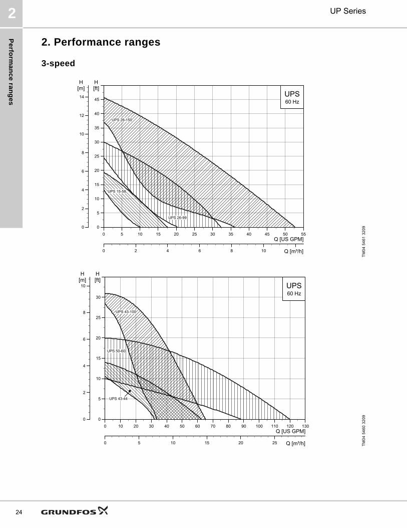
2. Performance ranges
3-speed
TM
04
54
61
32
09
0 5 10 15 20 25 30 35 40 45 50 55Q [US GPM]
0
5
10
15
20
25
30
35
40
45
[ft]H
0 2 4 6 8 10 Q [m³/h]
0
2
4
6
8
10
12
14
[m]H
UPS60 Hz
UPS 15-58
UPS 26-99
UPS 26-150
TM
04
54
60
32
09
0 10 20 30 40 50 60 70 80 90 100 110 120 130Q [US GPM]
0
5
10
15
20
25
30
[ft]H
0 5 10 15 20 25 Q [m³/h]
0
2
4
6
8
10[m]H
UPS60 Hz
UPS 43-44
UPS 50-60
UPS 43-100
Pe
rfo
rma
nc
e r
an
ge
s
UP Series 2
25
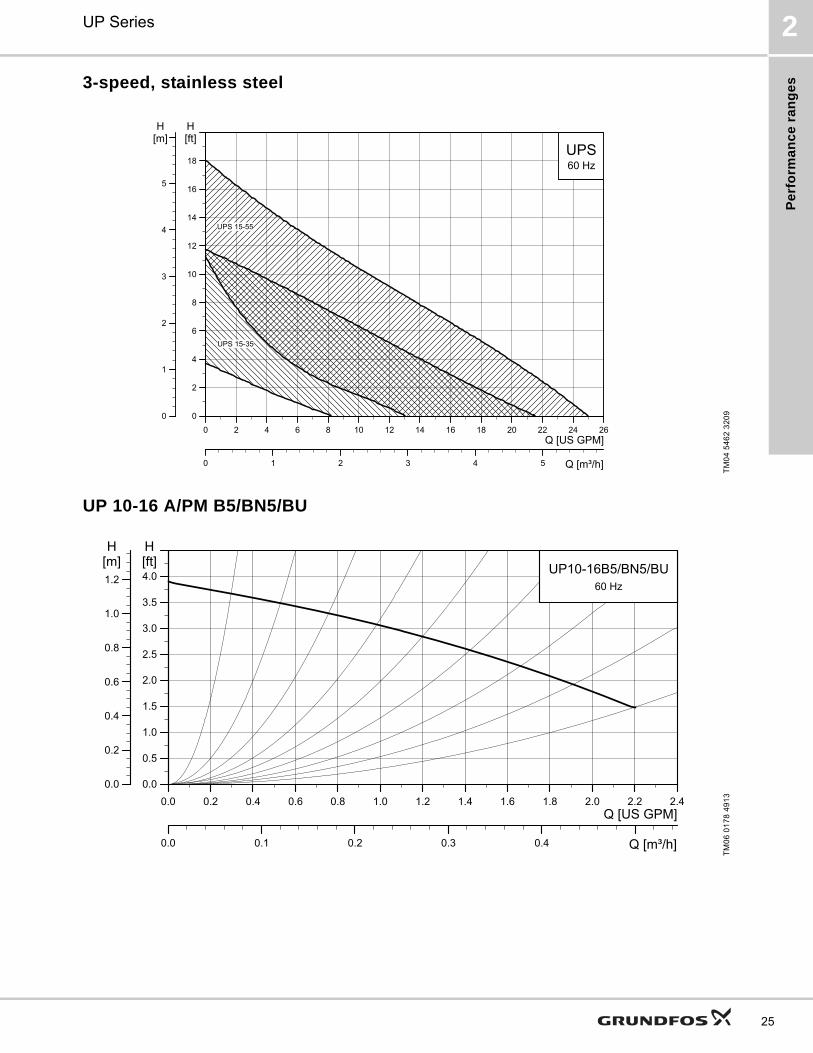
3-speed, stainless steel
UP 10-16 A/PM B5/BN5/BU
TM
04
54
62
32
09
0 2 4 6 8 10 12 14 16 18 20 22 24 26Q [US GPM]
0
2
4
6
8
10
12
14
16
18
[ft]H
0 1 2 3 4 5 Q [m³/h]
0
1
2
3
4
5
[m]H
UPS60 Hz
UPS 15-55
UPS 15-35
TM
06
01
78
49
13
0.0 0.2 0.4 0.6 0.8 1.0 1.2 1.4 1.6 1.8 2.0 2.2 2.4Q [US GPM]
0.0
0.5
1.0
1.5
2.0
2.5
3.0
3.5
4.0[ft]H
0.0
0.2
0.4
0.6
0.8
1.0
1.2[m]H
0.0 0.1 0.2 0.3 0.4 Q [m³/h]
UP10-16B5/BN5/BU60 Hz

Pe
rform
an
ce
ran
ge
s
UP Series2
26
Closed systems
Open systems
TM
03
91
28
35
07
0 4 8 12 16 20 24 28 32 36 40 44Q [US GPM]
0
4
8
12
16
20
24
28
32
36
[ft]H
0 2 4 6 8 Q [m³/h]
0
2
4
6
8
10
[m]H
1. UP 26-116 F
2. UP 26-99 F
3. UP 43-75 F
4. UP 26-96 F
5. UP 26-64 F
6. UP 15-42 F
7. UP 15-10 F/FR
8. UP 15-100 F
9. UP 26-120 U
9
8
7
6
5
4
3
2
1
TM
03
91
29
35
07
0 4 8 12 16 20 24 28 32 36 40 44 48 52 56 60 64Q [US GPM]
0
4
8
12
16
20
24
28
32
[ft]H
0 2 4 6 8 10 12 Q [m³/h]
0
2
4
6
8
10
[m]H
10. UP 26-99 BF
11. UP 43-75 BF
12. UP 26-96 BF
13. UPS 15-55 SU/SF
14. UPS 15-35 SU/SF
15. UP 15-29 SU/SF
16. UPS 26-99 BFC
17. UPS 43-44 BFC
17
16
15
14
1312
11
10
Pe
rfo
rma
nc
e r
an
ge
s
UP Series 2
27
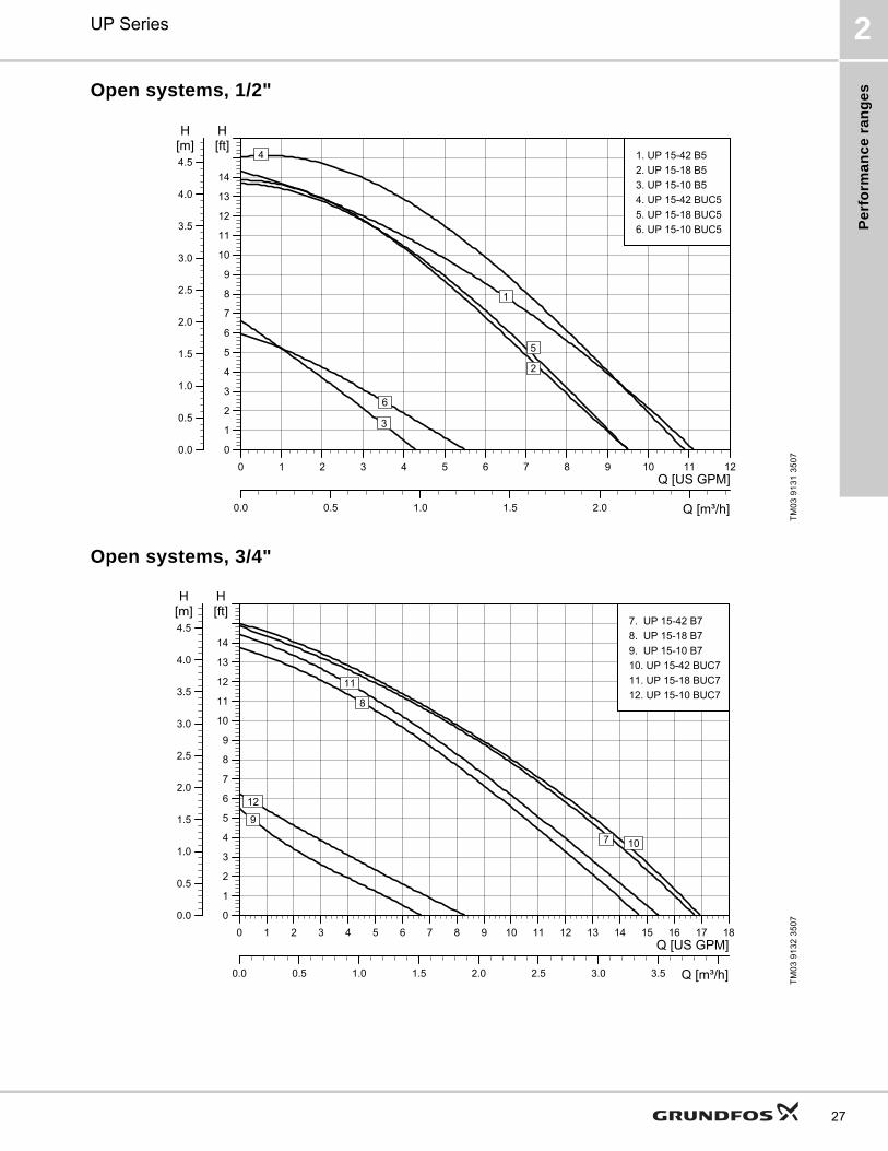
Open systems, 1/2"
Open systems, 3/4"
TM
03
91
31
35
07
0 1 2 3 4 5 6 7 8 9 10 11 12Q [US GPM]
0
1
2
3
4
5
6
7
8
9
10
11
12
13
14
[ft]H
0.0 0.5 1.0 1.5 2.0 Q [m³/h]
0.0
0.5
1.0
1.5
2.0
2.5
3.0
3.5
4.0
4.5
[m]H
1. UP 15-42 B5
2. UP 15-18 B5
3. UP 15-10 B5
4. UP 15-42 BUC5
5. UP 15-18 BUC5
6. UP 15-10 BUC5
6
4
5
3
2
1
TM
03
91
32
35
07
0 1 2 3 4 5 6 7 8 9 10 11 12 13 14 15 16 17 18Q [US GPM]
0
1
2
3
4
5
6
7
8
9
10
11
12
13
14
[ft]H
0.0 0.5 1.0 1.5 2.0 2.5 3.0 3.5 Q [m³/h]
0.0
0.5
1.0
1.5
2.0
2.5
3.0
3.5
4.0
4.5
[m]H
7. UP 15-42 B7
8. UP 15-18 B7
9. UP 15-10 B7
10. UP 15-42 BUC7
11. UP 15-18 BUC7
12. UP 15-10 BUC7
12
11
10
9
8
7
Pro
du
ct ra
ng
e
UP Series3
28
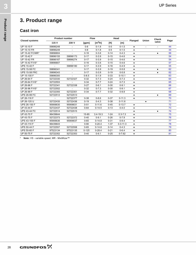
3. Product range
Cast iron
* Note: VS - variable speed, MR - MixiMizer™
Closed systemsProduct number Flow Head
Flanged UnionCheck valve
Page115 V 230 V [gpm] [m3/h] [ft] [m]
UP 15-10 F 59896248 - 0-8 0-1.8 0-5 0-1.5 ● - - 44
UP 15-10 FR 59896249 - 0-8 0-1.8 0-5 0-1.5 ● 44
UP 15-42 FC/MR* 59896804 - 0-16 0-3.6 0-14 0-4.3 ● ● 56
UP 15-42 F 59896155 59896173 0-17 0-3.9 0-15 0-4.6 ● 54
UP 15-42 FR 59896167 59896274 0-17 0-3.9 0-15 0-4.6 ● 54
UP 15-42 F/VS* 59896807 - 0-16 0-3.6 0-15 0-4.6 ● 57
UPS 15-42 F - 59896180 0-17 0-3.9 0-16 0-4.9 ● 55
UPS 15-58 FC 59896341 - 0-17 0-3.9 0-19 0-5.8 ● ● 62
UPS 15-58 FRC 59896343 - 0-17 0-3.9 0-19 0-5.8 ● ● 62
UP 15-100 F 59896300 - 0-8.5 0-1.9 0-33 0-10.1 ● 63
UP 26-64 F 52722330 52722327 0-32 0-7.3 0-24 0-7.3 ● 64
UP 26-64 F/VS* 52722553 - 0-34 0-7.7 0-24 0-7.3 ● 65
UP 26-96 F 52722341 52722338 0-27 0-6.1 0-30 0-9.1 ● 66
UP 26-96 F/VS* 52722552 - 0-32 0-7.3 0-30 0-9.1 ● 67
UP 26-99 F 52722355 52722351 0-34 0-7.7 0-32 0-9.8 ● 68
UPS 26-99 FC 52722512 52722513 ● ● 69
UP 26-116 F - 52722377 0-38 0-8.6 0-37 0-11.3 ● 70
UP 26-120 U 52722435 52722436 0-19 0-4.3 0-38 0-11.6 ● 71
UPS 26-150 F 95906630 95906631 0-51 0-11.6 0-45 0-13.7 ● 72
UP 43-44 F 52722437 52722438 0-64 0-14.5 0-13 0-4.0 ● 73
UPS 43-44 FC 52722514 52722515 ● ● 74
UP 43-70 F 96439644 - 15-85 3.4-19.3 1-24 0.3-7.3 ● 75
UP 43-75 F 52722373 52722372 0-40 0-9.1 0-26 0-7.9 ● 76
UPS 43-100 F 95906636 95906637 0-65 0-14.8 0-31 0-9.4 ● 77
UP 43-110 F 96439643 - 0-90 0-20.4 1-37 0.3-11.3 ● 78
UPS 50-44 F 52722557 52722558 0-65 0-14.8 0-14 0-4.3 ● 79
UPS 50-60 F 97523134 97523135 0-125 0-28.4 0-21 0-6.4 ● 80
UP 50-75 F 52722352 52722353 0-40 0-9.1 0-25 0-7.62 ● 81
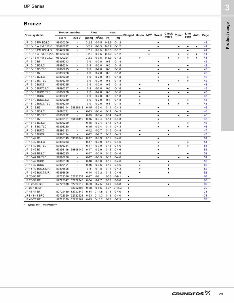
Pro
du
ct
ran
ge
UP Series 3
29
Bronze
* Note: MR - MixiMizer™
Open systemsProduct number Flow Head
Flanged Union NPT SweatCheck valve
TimerLine cord
Auto Page115 V 230 V [gpm] [m3/h] [ft] [m]
UP 10-16 PM B5/LC 98420206 - 0-2.2 0-0.5 0-3.9 0-1.2 ● 41
UP 10-16 A PM B5/LC 98420222 - 0-2.2 0-0.5 0-3.9 0-1.2 ● ● ● ● 41
UP 10-16 PM BN5/LC 98420210 - 0-2.2 0-0.5 0-3.9 0-1.2 ● ● 41
UP 10-16 A PM BN5/LC 98420223 - 0-2.2 0-0.5 0-3.9 0-1.2 ● ● ● ● 41
UP 10-16 A PM BU/LC 98420224 - 0-2.2 0-0.5 0-3.9 0-1.2 ● ● ● ● ● 41
UP 15-10 B5 59896213 - 0-9 0-2.0 0-6 0-1.8 ● 42
UP 15-10 B5/LC 59896214 - 0-9 0-2.0 0-6 0-1.8 ● ● 42
UP 15-10 B5/TLC 59896215 - 0-9 0-2.0 0-6 0-1.8 ● ● ● 42
UP 15-10 B7 59896226 - 0-9 0-2.0 0-6 0-1.8 ● 42
UP 15-10 B7/LC 59896209 - 0-9 0-2.0 0-6 0-1.8 ● ● 42
UP 15-10 B7/TLC 59896210 - 0-9 0-2.0 0-6 0-1.8 ● ● ● 42
UP 15-10 BUC5 59896225 - 0-9 0-2.0 0-6 0-1.8 ● ● 43
UP 15-10 BUC5/LC 59896237 - 0-9 0-2.0 0-6 0-1.8 ● ● ● 43
UP 15-10 BUC5/TLC 59896238 - 0-9 0-2.0 0-6 0-1.8 ● ● ● ● 43
UP 15-10 BUC7 59896241 - 0-9 0-2.0 0-6 0-1.8 ● ● 43
UP 15-10 BUC7/LC 59896239 - 0-9 0-2.0 0-6 0-1.8 ● ● ● 43
UP 15-10 BUC7/TLC 59896240 - 0-9 0-2.0 0-6 0-1.8 ● ● ● ● 43
UP 15-18 B5 59896114 59896118 0-15 0-3.4 0-14 0-4.3 ● 46
UP 15-18 B5/LC 59896211 - 0-15 0-3.4 0-14 0-4.3 ● ● 46
UP 15-18 B5/TLC 59896212 - 0-15 0-3.4 0-14 0-4.3 ● ● ● 46
UP 15-18 B7 59896121 59896119 0-15 0-3.4 0-14 0-4.3 ● 46
UP 15-18 B7/LC 59896229 - 0-15 0-3.4 0-14 0-4.3 ● ● 46
UP 15-18 B7/TLC 59896230 - 0-15 0-3.4 0-14 0-4.3 ● ● ● 46
UP 15-18 BUC5 59896123 - 0-12 0-2.7 0-16 0-4.9 ● ● 47
UP 15-18 BUC7 59896124 - 0-12 0-2.7 0-16 0-4.9 ● ● 47
UP 15-42 B5 59896145 59896142 0-17 0-3.9 0-15 0-4.6 ● 51
UP 15-42 B5/LC 59896233 - 0-17 0-3.9 0-15 0-4.6 ● ● 51
UP 15-42 B5/TLC 59896234 - 0-17 0-3.9 0-15 0-4.6 ● ● ● 51
UP 15-42 B7 59896146 59896149 0-17 0-3.9 0-15 0-4.6 ● 51
UP 15-42 B7/LC 59896235 - 0-17 0-3.9 0-15 0-4.6 ● ● 51
UP 15-42 B7/TLC 59896236 - 0-17 0-3.9 0-15 0-4.6 ● ● ● 51
UP 15-42 BUC5 59896150 - 0-16 0-3.6 0-15 0-4.6 ● ● 52
UP 15-42 BUC7 59896151 - 0-16 0-3.6 0-15 0-4.6 ● ● 52
UP 15-42 BUC5/MR* 59896805 - 0-8 0-1.8 0-14 0-4.3 ● ● 52
UP 15-42 BUC7/MR* 59896806 - 0-14 0-3.2 0-15 0-4.6 ● ● 52
UP 26-96 BF 52722336 52722334 0-27 0-6.1 0-30 0-9.1 ● 66
UP 26-99 BF 52722347 52722346 0-34 0-7.7 0-32 0-9.8 ● 68
UPS 26-99 BFC 52722518 52722519 0-33 0-7.5 0-29 0-8.8 ● ● 69
UP 26-116 BF - 52722393 0-38 0-8.6 0-37 0-11.3 ● 70
UP 43-44 BF 52722439 52722440 0-64 0-14.5 0-13 0-4.0 ● 73
UPS 43-44 BFC 52722520 52722521 0-63 0-14.3 0-13 0-4.0 ● ● 74
UP 43-75 BF 52722370 52722369 0-45 0-10.2 0-26 0-7.9 ● 76
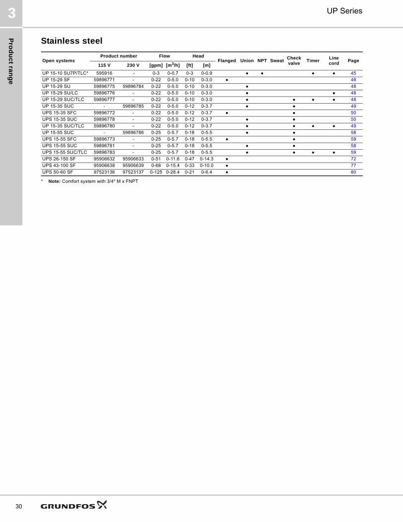
Pro
du
ct ra
ng
e
UP Series3
30
Stainless steel
* Note: Comfort system with 3/4" M x FNPT
Open systemsProduct number Flow Head
Flanged Union NPT SweatCheck valve
TimerLine cord
Page115 V 230 V [gpm] [m3/h] [ft] [m]
UP 15-10 SU7P/TLC* 595916 - 0-3 0-0.7 0-3 0-0.9 ● ● ● ● 45
UP 15-29 SF 59896771 - 0-22 0-5.0 0-10 0-3.0 ● 48
UP 15-29 SU 59896775 59896784 0-22 0-5.0 0-10 0-3.0 ● 48
UP 15-29 SU/LC 59896776 - 0-22 0-5.0 0-10 0-3.0 ● ● 48
UP 15-29 SUC/TLC 59896777 - 0-22 0-5.0 0-10 0-3.0 ● ● ● ● 48
UP 15-35 SUC - 59896785 0-22 0-5.0 0-12 0-3.7 ● ● 49
UPS 15-35 SFC 59896772 - 0-22 0-5.0 0-12 0-3.7 ● ● 50
UPS 15-35 SUC 59896778 - 0-22 0-5.0 0-12 0-3.7 ● ● 50
UP 15-35 SUC/TLC 59896780 - 0-22 0-5.0 0-12 0-3.7 ● ● ● ● 49
UP 15-55 SUC - 59896786 0-25 0-5.7 0-18 0-5.5 ● ● 58
UPS 15-55 SFC 59896773 - 0-25 0-5.7 0-18 0-5.5 ● ● 59
UPS 15-55 SUC 59896781 - 0-25 0-5.7 0-18 0-5.5 ● ● 58
UPS 15-55 SUC/TLC 59896783 - 0-25 0-5.7 0-18 0-5.5 ● ● ● ● 59
UPS 26-150 SF 95906632 95906633 0-51 0-11.6 0-47 0-14.3 ● 72
UPS 43-100 SF 95906638 95906639 0-68 0-15.4 0-33 0-10.0 ● 77
UPS 50-60 SF 97523136 97523137 0-125 0-28.4 0-21 0-6.4 ● 80
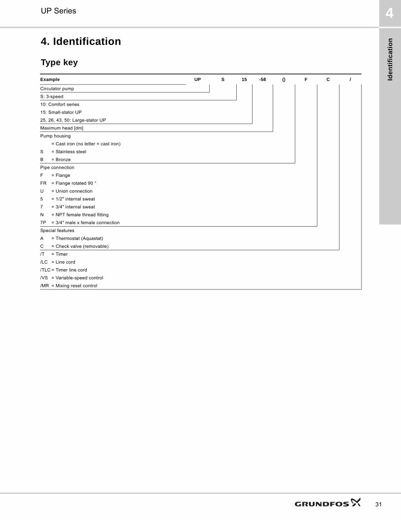
Ide
nti
fic
ati
on
UP Series 4
31
4. Identification
Type key
Example UP S 15 -58 () F C /
Circulator pump
S: 3-speed
10: Comfort series
15: Small-stator UP
25, 26, 43, 50: Large-stator UP
Maximum head [dm]
Pump housing
= Cast iron (no letter = cast iron)
S = Stainless steel
B = Bronze
Pipe connection
F = Flange
FR = Flange rotated 90 °
U = Union connection
5 = 1/2" internal sweat
7 = 3/4" internal sweat
N = NPT female thread fitting
7P = 3/4" male x female connection
Special features
A = Thermostat (Aquastat)
C = Check valve (removable)
/T = Timer
/LC = Line cord
/TLC = Timer line cord
/VS = Variable-speed control
/MR = Mixing reset control
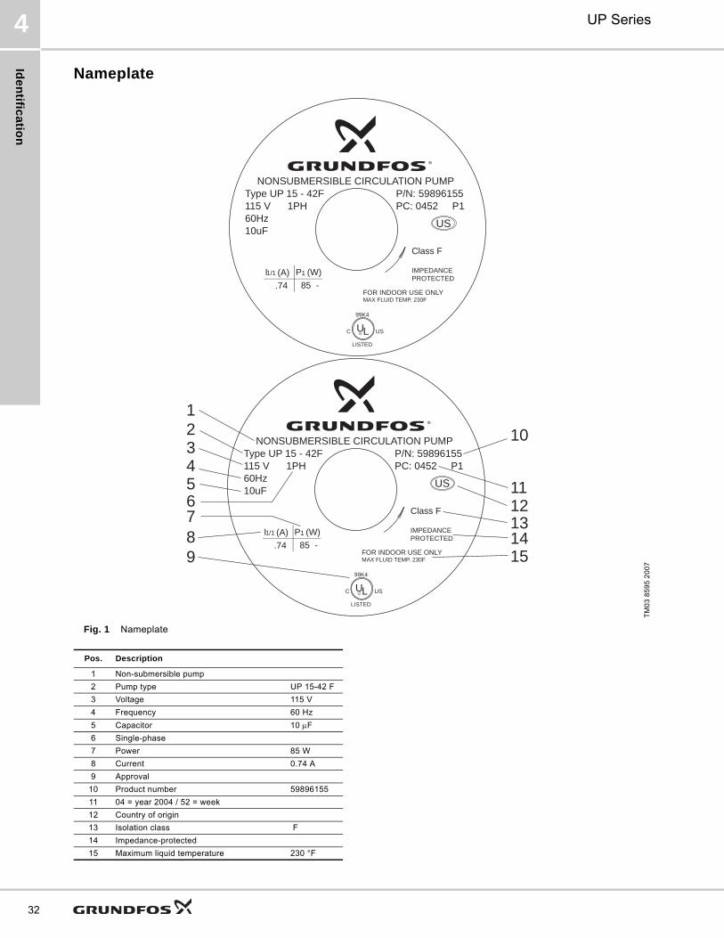
Ide
ntific
atio
n
UP Series4
32
Nameplate
Fig. 1 Nameplate
TM
03
85
95
20
07
NONSUBMERSIBLE CIRCULATION PUMP
I1/1 (A) P1 (W)
.74 85 -
US
3
567
4
21
89
121314
11
10
15
P/N: 59896155PC: 0452 P1
Type UP 15 - 42F115 V 1PH60Hz10uF
Class F
IMPEDANCEPROTECTED
FOR INDOOR USE ONLYMAX FLUID TEMP. 230F
C USUL
99K4
LISTED
NONSUBMERSIBLE CIRCULATION PUMP
I1/1 (A) P1 (W)
.74 85 -
US
P/N: 59896155PC: 0452 P1
Type UP 15 - 42F115 V 1PH60Hz10uF
Class F
IMPEDANCEPROTECTED
FOR INDOOR USE ONLYMAX FLUID TEMP. 230F
C USUL
99K4
LISTED
Pos. Description
1 Non-submersible pump
2 Pump type UP 15-42 F
3 Voltage 115 V
4 Frequency 60 Hz
5 Capacitor 10 F
6 Single-phase
7 Power 85 W
8 Current 0.74 A
9 Approval
10 Product number 59896155
11 04 = year 2004 / 52 = week
12 Country of origin
13 Isolation class F
14 Impedance-protected
15 Maximum liquid temperature 230 °F
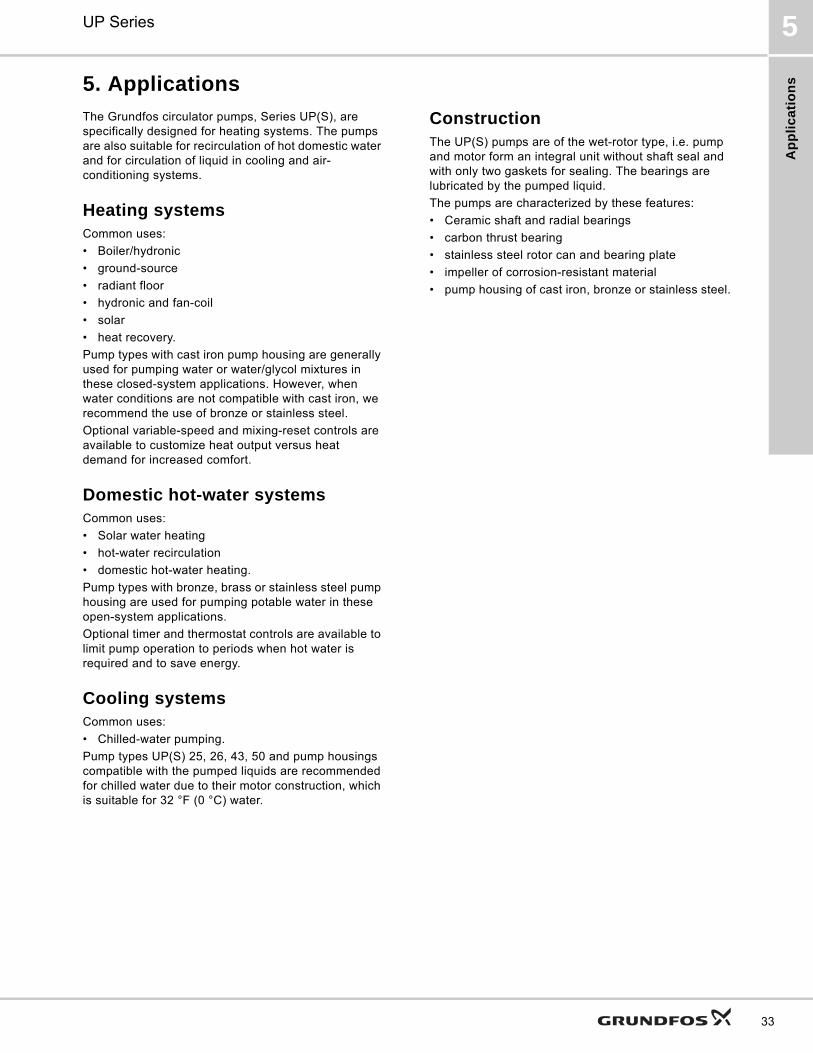
Ap
pli
ca
tio
ns
UP Series 5
33
5. Applications
The Grundfos circulator pumps, Series UP(S), are specifically designed for heating systems. The pumps are also suitable for recirculation of hot domestic water and for circulation of liquid in cooling and air-conditioning systems.
Heating systemsCommon uses:
• Boiler/hydronic
• ground-source
• radiant floor
• hydronic and fan-coil
• solar
• heat recovery.
Pump types with cast iron pump housing are generally used for pumping water or water/glycol mixtures in these closed-system applications. However, when water conditions are not compatible with cast iron, we recommend the use of bronze or stainless steel.
Optional variable-speed and mixing-reset controls are available to customize heat output versus heat demand for increased comfort.
Domestic hot-water systemsCommon uses:
• Solar water heating
• hot-water recirculation
• domestic hot-water heating.
Pump types with bronze, brass or stainless steel pump housing are used for pumping potable water in these open-system applications.
Optional timer and thermostat controls are available to limit pump operation to periods when hot water is required and to save energy.
Cooling systemsCommon uses:
• Chilled-water pumping.
Pump types UP(S) 25, 26, 43, 50 and pump housings compatible with the pumped liquids are recommended for chilled water due to their motor construction, which is suitable for 32 °F (0 °C) water.
ConstructionThe UP(S) pumps are of the wet-rotor type, i.e. pump and motor form an integral unit without shaft seal and with only two gaskets for sealing. The bearings are lubricated by the pumped liquid.
The pumps are characterized by these features:
• Ceramic shaft and radial bearings
• carbon thrust bearing
• stainless steel rotor can and bearing plate
• impeller of corrosion-resistant material
• pump housing of cast iron, bronze or stainless steel.

Ap
plic
atio
ns
UP Series5
34
Materials of construction InstallationThe pump must always be installed with horizontal motor shaft.
Proper installation of the pump will have the terminal box located to one side of the pump or the other, with the conduit entry down.
UP(S) can be installed in both vertical and horizontal lines.
UP(S) pumps are intended for indoor use only.
Fig. 2
MotorThe motor is a 2-pole, asynchronous, squirrel-cage PSC (permanent split capacitor) motor with UL, CUL, ETL and CSA approvals.
UP(S) pumps are available in single-phase 115 V and 230 V versions with one or three speeds.
The terminal box is easily accessible and has functional cables connecting leads or terminals.
Insulation class(es): F, H.
The motor incorporates thermal overload or impedance protection. Therefore, no external motor protection is required.
UP models are single-speed pumps.
UPS model pumps are multi-speed pumps, and the speed can be changed by means of a speed selector switch located on the front of the terminal box.
If the speed of UPS 15-35 or 15-55 TLC models has to be changed, the timer control has to be removed before the speed can be changed.
UP models with VS or MR suffixes are variable-speed pumps with integrated control.
Depending on pump model, motor horsepowers range from 1/25 to 1/6 and power consumption from 5 to 385 W.
Description (UP closed systems)
Material
Inlet cone, bearing plate, bearing retainers, rotor can, rotor cladding, shaft retainer
Stainless steel
Stator housing Aluminium
Shaft, upper and lower radial bearings
Aluminium oxide ceramic
Thrust bearingCarbon bearing and EPDM retainer
Check valveACETAL with 302 stainless steel spring and nitrile rubber seats
Pump housing (volute) Cast iron
O-ring and gasketsEPDM (ethylene propylene rubber)
Impeller PES composite (30 % glass-filled)
Terminal box Noryl® with EPDM gasket
Description (UP open systems) Material
Inlet cone, bearing plate, bearing retainers, rotor can, rotor cladding, shaft retainer
Stainless steel
Volute retainer (SU & SF models) and stator housing
Aluminium
Shaft, upper and lower radial bearings
Aluminium oxide ceramic
Thrust bearingCarbon bearing and EPDM retainer
Pump housing (volute)Silicon bronze C875 or stainless steel 300 series.
O-ring and gasketsEPDM (ethylene propylene rubber)
Impeller PES composite (30 % glass-filled)
Terminal box Noryl® with EPDM gasket
Description (BUC5 and BUC7) Material
Inlet cone, bearing plate, bearing retainers, rotor can, rotor cladding, shaft retainer, check valve spring
Stainless steel
Stator housing Aluminium
Shaft, upper and lower radial bearings
Aluminium oxide ceramic
Thrust bearingCarbon bearing and EPDM retainer
Pump housing (volute) Silicon bronze C875 lead free
Tail piece and union nut Brass (UNS C36000)
O-ring and gasketsEPDM (ethylene propylene rubber)
Impeller PES composite (30 % glass-filled)
Terminal box Noryl® with EPDM gasket
Check valve housingACETAL with 302 stainless steel, spring and nitrile rubber seat
Union gasket EPDM
TM
04
50
58
25
09
Ap
pli
ca
tio
ns
UP Series 5
35
Pumped liquidsDepending on type, Grundfos circulator pumps are designed for the following liquids:
• Potable water
• non-potable water
• water-glycol mixtures
• chilled water
• domestic hot water
• softened water.
If the circulator pump is used for a glycol mixture with a higher viscosity than that of water, the hydraulic performance of the pump will be reduced.
Example: 50 % glycol at 68 °F (20 °C) means a viscosity of approx. 10 cSt and a reduction of pump performance by approx. 15 %.
When selecting a pump, the viscosity of the pumped liquid must be taken into consideration.
Ambient and liquid temperaturesThe maximum allowable water temperature is determined by the ambient air temperature as shown in the table below.
Note: This table refers to all standard products without timer, control options or other special features.
• If the UP pump is equipped with a timer, the maximum liquid temperature is 150 °F (66 °C).
• Temperature requirements for pumps with timer, control or other special features may be found on their technical data page. See section Technical data, pages 41-81.
The ambient temperature for standard pumps with a permissible liquid temperature from 36 °F (2 °C) to 230 °F (110 °C) should always be lower than the liquid temperature, as otherwise condensation may form in the stator housing.
Maximum system pressure145 psi (10 bar).
Minimum inlet pressureThe pressure required at the inlet of a pump is a function of the temperature of the water as shown in the table below.
Performance
Flow range 0-120 gpm (0 - 27.3 m3/h)
Head range 0-46 ft (0-14 m)
In a pressure system, the required inlet pressure is the allowable system pressure.
In a system open to the atmosphere, the required inlet pressure is the minimum distance the pump must be located below the lowest possible water level of the water source (tank, pool, etc.).
Maximum water temperature
Ambient [°F (°C)]104(40)
120(49)
140(60)
160(71)
175(79)
Water, all cast iron [°F (°C)]230
(110)220
(104)210(99)
190(88)
175(79)
Water, all bronze and stainless steel
220(104)
210(99)
190(88)
175(79)
The pump models below are exceptions to the temperatures listed above:
UP/UPS 15 FC and UP 43 FC [°F (°C)]
200(93)
190(88)
180(82)
170(77)
UP 15 BUC5 and UP 15 BUC7 [°F (°C)]
200(93)
190(88)
180(82)
170(77)
UPS 15-35 [°F (°C)]165(74)
140(60)
- - -
UP 15-100 F [°F (°C)]205(96)
195(91)
185(85)
175(79)
-
UP 26-120 U [°F (°C)]205(96)
195(91)
185(85)
175(79)
-
UP 26-116 [°F (°C)]150(66)
140(60)
- - -
Liquid temperature
UP(S) model
[140 °F (60 °C)]
[165 °F (74 °C)]
[190 °F (88 °C)]
[230 °F (110 °C)]
[psi] [bar] [psi] [bar] [psi] [bar] [psi] [bar]
UP(S) 15
1.3 0.1
1.9 0.1 4.0 0.3 15.6 1.1UP(S) 26
UP(S) 43
UPS 26-150 1.3 0.09 2.6 0.18 7.8 0.54
UPS 43-100 2.1 0.15 5.6 0.40 11.3 0.80
UPS 50-60 0.5 0.04 1.0 0.07 1.3 0.09 7.0 0.49
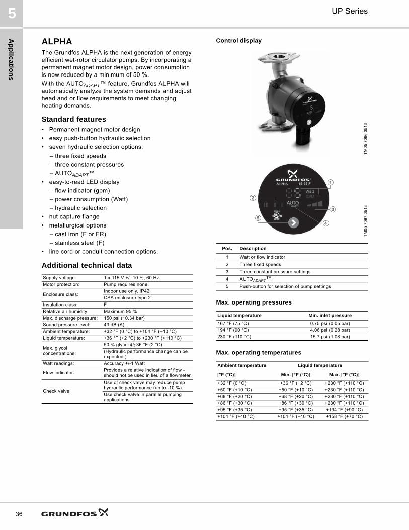
Ap
plic
atio
ns
UP Series5
36
ALPHAThe Grundfos ALPHA is the next generation of energy efficient wet-rotor circulator pumps. By incorporating a permanent magnet motor design, power consumption is now reduced by a minimum of 50 %.
With the AUTOADAPT™ feature, Grundfos ALPHA will automatically analyze the system demands and adjust head and or flow requirements to meet changing heating demands.
Standard features• Permanent magnet motor design
• easy push-button hydraulic selection
• seven hydraulic selection options:
– three fixed speeds
– three constant pressures
– AUTOADAPT™• easy-to-read LED display
– flow indicator (gpm)
– power consumption (Watt)
– hydraulic selection
• nut capture flange
• metallurgical options
– cast iron (F or FR)
– stainless steel (F)
• line cord or conduit connection options.
Additional technical data
Control display
Max. operating pressures
Max. operating temperatures
Supply voltage: 1 x 115 V +/- 10 %, 60 Hz
Motor protection: Pump requires none.
Enclosure class:Indoor use only, IP42
CSA enclosure type 2
Insulation class: F
Relative air humidity: Maximum 95 %
Max. discharge pressure: 150 psi (10.34 bar)
Sound pressure level: 43 dB (A)
Ambient temperature: +32 °F (0 °C) to +104 °F (+40 °C)
Liquid temperature: +36 °F (+2 °C) to +230 °F (+110 °C)
Max. glycol concentrations:
50 % glycol @ 36 °F (2 °C)
(Hydraulic performance change can be expected.)
Watt readings: Accuracy +/-1 Watt
Flow indicator:Provides a relative indication of flow - should not be used in lieu of a flowmeter.
Check valve:
Use of check valve may reduce pump hydraulic performance (up to -10 %).
Use check valve in parallel pumping applications.
TM
05
70
96
05
13
TM
05
70
97
05
13
Pos. Description
1 Watt or flow indicator
2 Three fixed speeds
3 Three constant pressure settings
4 AUTOADAPT™5 Push-button for selection of pump settings
Liquid temperature Min. inlet pressure
167 °F (75 °C) 0.75 psi (0.05 bar)
194 °F (90 °C) 4.06 psi (0.28 bar)
230 °F (110 °C) 15.7 psi (1.08 bar)
Ambient temperature Liquid temperature
[°F (°C)] Min. [°F (°C)] Max. [°F (°C)]
+32 °F (0 °C) +36 °F (+2 °C) +230 °F (+110 °C)
+50 °F (+10 °C) +50 °F (+10 °C) +230 °F (+110 °C)
+68 °F (+20 °C) +68 °F (+20 °C) +230 °F (+110 °C)
+86 °F (+30 °C) +86 °F (+30 °C) +230 °F (+110 °C)
+95 °F (+35 °C) +95 °F (+35 °C) +194 °F (+90 °C)
+104 °F (+40 °C) +104 °F (+40 °C) +158 °F (+70 °C)
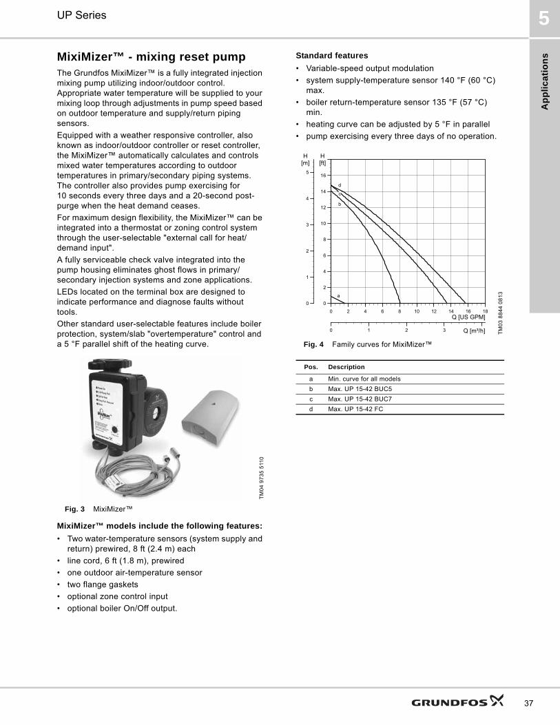
Ap
pli
ca
tio
ns
UP Series 5
37
MixiMizer™ - mixing reset pumpThe Grundfos MixiMizer™ is a fully integrated injection mixing pump utilizing indoor/outdoor control. Appropriate water temperature will be supplied to your mixing loop through adjustments in pump speed based on outdoor temperature and supply/return piping sensors.
Equipped with a weather responsive controller, also known as indoor/outdoor controller or reset controller, the MixiMizer™ automatically calculates and controls mixed water temperatures according to outdoor temperatures in primary/secondary piping systems. The controller also provides pump exercising for 10 seconds every three days and a 20-second post-purge when the heat demand ceases.
For maximum design flexibility, the MixiMizer™ can be integrated into a thermostat or zoning control system through the user-selectable "external call for heat/demand input".
A fully serviceable check valve integrated into the pump housing eliminates ghost flows in primary/secondary injection systems and zone applications.
LEDs located on the terminal box are designed to indicate performance and diagnose faults without tools.
Other standard user-selectable features include boiler protection, system/slab "overtemperature" control and a 5 °F parallel shift of the heating curve.
Fig. 3 MixiMizer™
MixiMizer™ models include the following features:
• Two water-temperature sensors (system supply and return) prewired, 8 ft (2.4 m) each
• line cord, 6 ft (1.8 m), prewired
• one outdoor air-temperature sensor
• two flange gaskets
• optional zone control input
• optional boiler On/Off output.
Standard features
• Variable-speed output modulation
• system supply-temperature sensor 140 °F (60 °C) max.
• boiler return-temperature sensor 135 °F (57 °C) min.
• heating curve can be adjusted by 5 °F in parallel
• pump exercising every three days of no operation.
Fig. 4 Family curves for MixiMizer™
TM
04
97
35
511
0
TM
03
88
44
08
13
Pos. Description
a Min. curve for all models
b Max. UP 15-42 BUC5
c Max. UP 15-42 BUC7
d Max. UP 15-42 FC
0 2 4 6 8 10 12 14 16 18Q [US GPM]
0
2
4
6
8
10
12
14
16
[ft]H
0
1
2
3
4
5
[m]H
0 1 2 3 Q [m³/h]
a
d
c
b

Ap
plic
atio
ns
UP Series5
38
Variable-speed pumpThe Grundfos variable-speed pump is another product with fully integrated control. The variable-speed controller requires a 0-10/2-10 VDC or 0-20/4-20 mA control signal, which is user-selectable.
If desired, the manual-% dial allows the speed of the pump to be manually adjusted and set by the user. The speed of the pump may be manually adjusted anywhere from min. to 100 %, but once set, remains fixed at that speed.
In addition, the pump speed may be set as 0-100 % or 15-100 % by user.
The controller also provides pump exercising for 10 seconds every three days and a power-up reset, which runs the pump for three seconds at full speed, for all modes of operation.
LEDs on the terminal box indicate operation (power is applied) and performance (flashing slowly or quickly).
Fig. 5 Variable-speed pump
Variable-speed models include the following items:
• Pump with integrated variable-speed control
• line cord, 6 ft (1.8 m), prewired
• two gaskets.
Variable-speed standard features
• Variable-speed output modulation (external or manual control)
• offset-dial for fine-tuning of the signal input.
Fig. 6 Family curves for variable-speed pumpsT
M0
3 9
08
8 0
51
3
Signal type Signal range
Voltage 0-10 VDC or 2-10 VDC, 5 mA max.
Current 0-20 mA or 4-20 mA, 5 VDC max.
TM
03
88
43
08
13
Pos. Description
a Min. curve for all models
b Max. UP 15-42 F/VS
c Max. UP 26-64 F/VS
d Max. UP 26-96 F/VS
0 4 8 12 16 20 24 28 32 36Q [US GPM]
0
4
8
12
16
20
24
28
32
[ft]H
0 2 4 6 Q [m³/h]
0
2
4
6
8
10
[m]H
a
d
c
b

Ap
pli
ca
tio
ns
UP Series 5
39
Comfort SystemThe Comfort System uses a patented Comfort Valve® and pump to provide instant availability of hot water at the point of use.
Operation
The Comfort Valve® is installed at the fixture furthest away from the hot-water tank. With a built-in timer, the pump allows hot water to circulate along the loop through the valve using the cold-water side as a return line. As the temperature rises to 100 °F (38 °C), the valve closes, thus resulting in a constant availability of hot water.
Savings
The Comfort System saves up to 16,000 gallons (60,566 liters) of water per year and per household (based on average modern household usage) and uses less energy than a 25 W light bulb.
Applications
• Domestic hot-water recirculation systems in single- and two-family houses.
Pumped liquids
• Domestic hot water
• potable and non-potable water.
Fig. 7 Comfort System
Motor
• Insulation class: F
• power consumption: 25 W
• voltage: 115 V
• current: 0.23 A
• phase: 1.
Grundfos Comfort Valve® materials listing
Ambient and liquid temperatures
Liquid temperature: 36 °F (2 °C) to 150 °F (66 °C).
It is recommended to keep the operating temperature as low as possible (e.g. 140 °F (60 °C)) to avoid calcium precipitation.
The ambient temperature should always be lower than the liquid temperature, as otherwise condensation may form in the stator housing.
Maximum system pressure
145 psi (10 bar).
Fig. 8 Performance curve for the Comfort System
TM
03
91
26
05
13
Description (UP open systems) Material
Inlet cone, bearing plate, bearing retainers, rotor can, rotor cladding, shaft retainer
Stainless steel
Volute retainer (SU & SF models) and stator housing
Aluminium
Shaft, upper and lower radial bearings
Aluminium oxide ceramic
Thrust bearingCarbon bearing and EPDM retainer
Pump housing (volute)Silicon bronze C875 or stainless steel 300 series.
O-ring and gasketsEPDM (ethylene propylene rubber)
Impeller PES composite (30 % glass-filled)
Terminal box Noryl® with EPDM gasket
Description Trade name Material
Springs, pins, screens 300 Series Stainless steel
Valve housing Ryton PPS
Thermal actuator housing
300 Series Stainless steel
Check valve O-ring EPDM
Check valve housing Acetal
Check valve plunger Thermoplastic
TM
03
55
47
44
12
0.0 0.5 1.0 1.5 2.0 2.5 3.0 3.5 4.0 4.5 5.0 5.5 Q [US GPM]0.0
0.5
1.0
1.5
2.0
2.5
3.0
3.5
4.0
4.5
5.0
[ft]H
0.0 0.2 0.4 0.6 0.8 1.0 1.2 Q [m³/h]
0.0
0.2
0.4
0.6
0.8
1.0
1.2
1.4
[m]H
UP15-10SU7P/TLC60 Hz
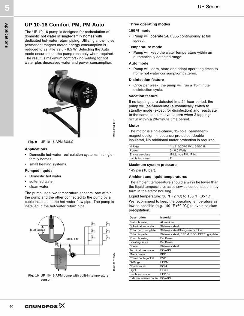
Ap
plic
atio
ns
UP Series5
40
UP 10-16 Comfort PM, PM AutoThe UP 10-16 pump is designed for recirculation of domestic hot water in single-family homes with dedicated hot-water return piping. Utilizing a low-noise permanent magnet motor, energy consumption is reduced to as little as 5 - 8.5 W. Selecting the Auto mode ensures that the pump runs only when required. The result is maximum comfort - no waiting for hot water plus decreased water and power consumption.
Fig. 9 UP 10-16 APM BU/LC
Applications
• Domestic hot-water recirculation systems in single-family homes
• small heating systems.
Pumped liquids
• Domestic hot water
• softened water
• clean water.
The pump uses two temperature sensors, one within the pump and the other connected to the pump by a cable installed in the hot-water flow pipe. The pump is installed in the hot-water return pipe.
Fig. 10 UP 10-16 APM pump with built-in temperature sensor
Three operating modes
100 % mode
• Pump will operate 24/7/365 continuously at full speed.
Temperature mode
• Pump will keep the water temperature within an automatically detected range.
Auto mode
• Pump will learn, store and adapt operating times to home hot water consumption patterns.
Disinfection feature
• Once per week, the pump will run a 15-minute disinfection cycle.
Vacation feature
If no tappings are detected in a 24-hour period, the pump will (self-modulate) automatically switch to standby mode (except for disinfection) and reactivate to the same consumptive pattern when 2 tappings occur within a 20-minute time period.
Motor
The motor is single-phase, 12-pole, permanent-magnet design, impedance-protected, double insulated, No additional motor protection is required.
Maximum system pressure
145 psi (10 bar).
Ambient and liquid temperatures
The ambient temperature should always be lower than the liquid temperature, as otherwise condensation may form in the stator housing.
Liquid temperature: 36 °F (2 °C) to 185 °F (85 °C).
We recommend to keep the operating temperature as low as possible (e.g. 140 °F (60 °C)) to avoid calcium precipitation.
TM
06
00
34
47
13
TM
06
10
73
15
14
8-20 inches
Max. 8 ft.
Voltage 1 x 115/208-230 V, 50/60 Hz
Power 5 - 8.5 Watts
Enclosure class IP42, type PM: IP44
Insulation class F
Description Material
Stator housing Aluminium
Spherical separator Stainless steel
Rotor can, complete Stainless steel/Tungsten carbide
Rotor, impeller Stainless steel, EPDM, PPO, PFTE, graphite
Pump housing EcoBrass
Isolating valve EcoBrass
Screw Stainless steel
Terminal box cover PC/ABS
Motor cover PPO
Power cable jacket PVC
O-Rings EPDM
Check valve POM
Light Lexan
Insulation cover EPP 55
External sensor cable PC/ABS

Tec
hn
ica
l d
ata
UP Series 6
41
6. Technical data
UP 10-16 Comfort PM, PM Auto
UP 10-16 A/PM B5/BN5/BU
Approvals
Note: Models have a 6 ft (1.8 m), 3-prong power cord. Maximum external sensor cable length 8 ft (2.4 m). UP 10-16 A PM BU/LC with integral check valve. Dimensions in inches unless otherwise noted.
TM
06
01
78
49
13
0.0 0.2 0.4 0.6 0.8 1.0 1.2 1.4 1.6 1.8 2.0 2.2 2.4Q [US GPM]
0.0
0.5
1.0
1.5
2.0
2.5
3.0
3.5
4.0[ft]H
0.0
0.2
0.4
0.6
0.8
1.0
1.2[m]H
0.0 0.1 0.2 0.3 0.4 Q [m³/h]
UP10-16B5/BN5/BU60 Hz
Flow range: 0 - 2.2 gpm (0 - 0.5 m3/h)
Head range: 0 - 3.9 ft (0 - 1.2 m)
Motors: Single-phase
Max. liquid temperature: 185 °F (85 °C)
Min. liquid temperature: 36 °F (2 °C)
Max. system pressure: 145 psi (10 bar)
Model Volts Amps Watts Hp Capacitor
UP 10-16 B5/BN5/BU
115/208-230 V 0.23 5 - 8.5 - -
Drinking Water System ComponentsIn Accordance with NSF/ANSI 372
UP 10-16 PM B5, BN5APM B5, BN5
UP 10-16 APM BU
TM
06
06
49
06
14
TM
06
06
84
07
14
ModelProduct number
115/208-230 V
Dimensions [inches (mm)] Shippingweight
[lbs (kg)]L1 H1 H2 H3 B1 B2 Connection
UP10-16 PM B5/LC 98420206 3.13 (79)
1.0 (25.4)
0.5 (12.7)
5.25 (133) 2.67 (68) 3.28 (83)
1/2" Sweat 2.9 (1.3)
UP10-16 PM BN5/LC 98420210 3.13 (79) 0.5 (12.7) 1/2" NPT 3.4 (1.5)
UP10-16 A PM B5/LC 98420222 3.13 (79) 0.5 (12.7) 1/2" Sweat 2.9 (1.3)
UP10-16 A PM BN5/LC 98420223 3.13 (79) 0.5 (12.7) 1/2" NPT 3.4 (1.5)
UP10-16 A PM BU/LC 98420224 4.33 (110) 0.88 (23) 1 1/4" NPSM 3.8 (1.7)
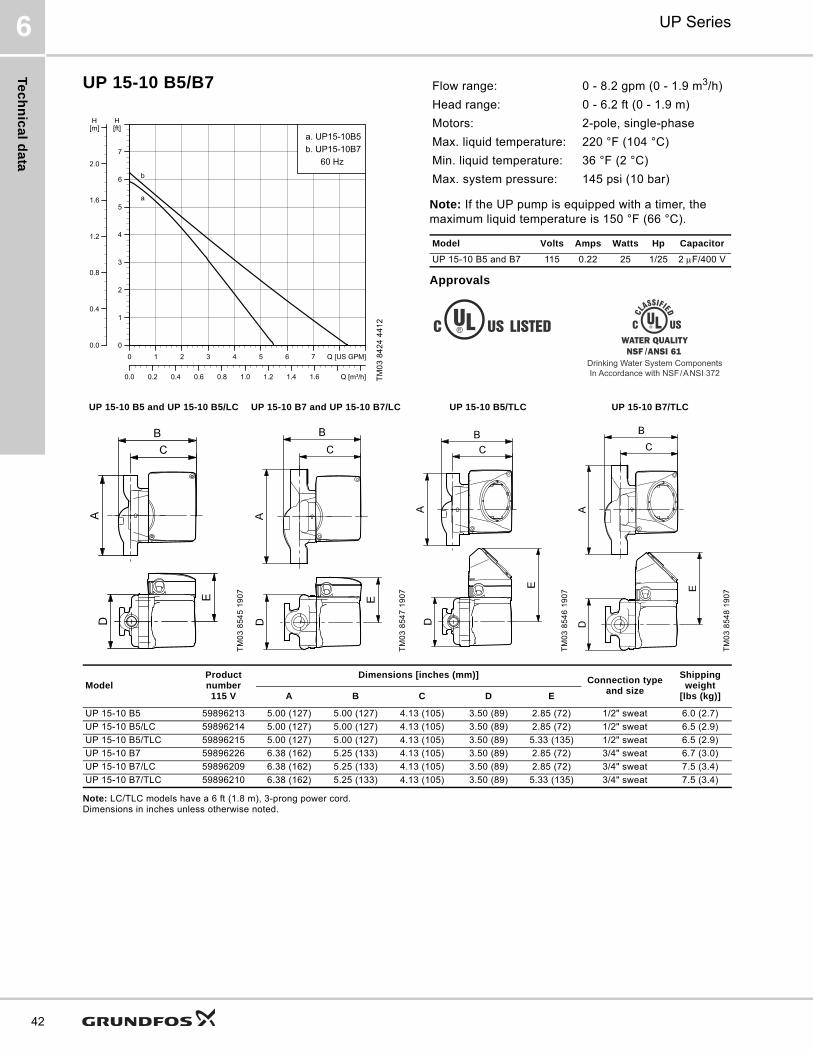
Te
ch
nic
al d
ata
UP Series6
42
UP 15-10 B5/B7
Note: If the UP pump is equipped with a timer, the maximum liquid temperature is 150 °F (66 °C).
Approvals
Note: LC/TLC models have a 6 ft (1.8 m), 3-prong power cord. Dimensions in inches unless otherwise noted.
TM
03
84
24
44
12
0 1 2 3 4 5 6 7 Q [US GPM]0
1
2
3
4
5
6
7
[ft]H
0.0 0.2 0.4 0.6 0.8 1.0 1.2 1.4 1.6 Q [m³/h]
0.0
0.4
0.8
1.2
1.6
2.0
[m]H
a. UP15-10B5b. UP15-10B7
60 Hz
a
b
Flow range: 0 - 8.2 gpm (0 - 1.9 m3/h)
Head range: 0 - 6.2 ft (0 - 1.9 m)
Motors: 2-pole, single-phase
Max. liquid temperature: 220 °F (104 °C)
Min. liquid temperature: 36 °F (2 °C)
Max. system pressure: 145 psi (10 bar)
Model Volts Amps Watts Hp Capacitor
UP 15-10 B5 and B7 115 0.22 25 1/25 2 F/400 V
Drinking Water System ComponentsIn Accordance with NSF/ANSI 372
UP 15-10 B5 and UP 15-10 B5/LC UP 15-10 B7 and UP 15-10 B7/LC UP 15-10 B5/TLC UP 15-10 B7/TLC
TM
03
85
45
19
07
TM
03
85
47
19
07
TM
03
85
46
19
07
TM
03
85
48
19
07
ModelProduct number115 V
Dimensions [inches (mm)]Connection type
and size
Shipping weight
[lbs (kg)]A B C D E
UP 15-10 B5 59896213 5.00 (127) 5.00 (127) 4.13 (105) 3.50 (89) 2.85 (72) 1/2" sweat 6.0 (2.7)
UP 15-10 B5/LC 59896214 5.00 (127) 5.00 (127) 4.13 (105) 3.50 (89) 2.85 (72) 1/2" sweat 6.5 (2.9)
UP 15-10 B5/TLC 59896215 5.00 (127) 5.00 (127) 4.13 (105) 3.50 (89) 5.33 (135) 1/2" sweat 6.5 (2.9)
UP 15-10 B7 59896226 6.38 (162) 5.25 (133) 4.13 (105) 3.50 (89) 2.85 (72) 3/4" sweat 6.7 (3.0)
UP 15-10 B7/LC 59896209 6.38 (162) 5.25 (133) 4.13 (105) 3.50 (89) 2.85 (72) 3/4" sweat 7.5 (3.4)
UP 15-10 B7/TLC 59896210 6.38 (162) 5.25 (133) 4.13 (105) 3.50 (89) 5.33 (135) 3/4" sweat 7.5 (3.4)
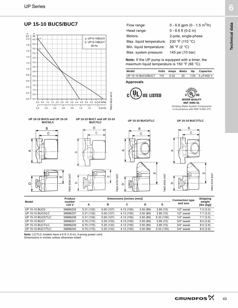
Tec
hn
ica
l d
ata
UP Series 6
43
UP 15-10 BUC5/BUC7
Note: If the UP pump is equipped with a timer, the maximum liquid temperature is 150 °F (66 °C).
Approvals
Note: LC/TLC models have a 6 ft (1.8 m), 3-prong power cord. Dimensions in inches unless otherwise noted.
TM
03
84
25
44
12
0.0 0.5 1.0 1.5 2.0 2.5 3.0 3.5 4.0 4.5 5.0 5.5 Q [US GPM]0.0
0.5
1.0
1.5
2.0
2.5
3.0
3.5
4.0
4.5
5.0
5.5
6.0
6.5
[ft]H
0.0 0.2 0.4 0.6 0.8 1.0 1.2 Q [m³/h]
0.0
0.2
0.4
0.6
0.8
1.0
1.2
1.4
1.6
1.8
2.0[m]H
a. UP15-10BUC5b. UP15-10BUC7
60 Hz
a
b
Flow range: 0 - 6.6 gpm (0 - 1.5 m3/h)
Head range: 0 - 6.6 ft (0-2 m)
Motors: 2-pole, single-phase
Max. liquid temperature: 230 °F (110 °C)
Min. liquid temperature: 36 °F (2 °C)
Max. system pressure: 145 psi (10 bar)
Model Volts Amps Watts Hp Capacitor
UP 15-10 BUC5/BUC7 115 0.22 25 1/25 2 F/400 V
Drinking Water System ComponentsIn Accordance with NSF/ANSI 372
UP 15-10 BUC5 and UP 15-10 BUC5/LC
UP 15-10 BUC7 and UP 15-10 BUC7/LC
UP 15-10 BUC5/TLC UP 15-10 BUC7/TLC
TM
03
85
49
24
07
TM
03
87
53
50
07
TM
03
85
50
24
07
TM
03
87
54
50
07
ModelProduct number115 V
Dimensions [inches (mm)]Connection type
and size
Shipping weight
[lbs (kg)]A B C D E
UP 15-10 BUC5 59896225 5.31 (135) 5.00 (127) 4.13 (105) 3.50 (89) 2.85 (72) 1/2" sweat 7.3 (3.3)
UP 15-10 BUC5/LC 59896237 5.31 (135) 5.00 (127) 4.13 (105) 3.50 (89) 2.85 (72) 1/2" sweat 7.7 (3.5)
UP 15-10 BUC5/TLC 59896238 5.31 (135) 5.00 (127) 4.13 (105) 3.50 (89) 5.33 (135) 1/2" sweat 7.7 (3.5)
UP 15-10 BUC7 59896241 6.70 (170) 5.25 (133) 4.13 (105) 3.50 (89) 2.85 (72) 3/4" sweat 8.0 (3.6)
UP 15-10 BUC7/LC 59896239 6.70 (170) 5.25 (133) 4.13 (105) 3.50 (89) 2.85 (72) 3/4" sweat 8.5 (3.9)
UP 15-10 BUC7/TLC 59896240 6.70 (170) 5.25 (133) 4.13 (105) 3.50 (89) 5.33 (135) 3/4" sweat 8.5 (3.9)
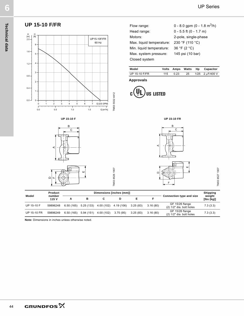
Te
ch
nic
al d
ata
UP Series6
44
UP 15-10 F/FR
Approvals
Note: Dimensions in inches unless otherwise noted.
TM
03
55
32
44
12
0 1 2 3 4 5 6 7 Q [US GPM]0
1
2
3
4
5
6
[ft]H
0.0 0.5 1.0 1.5 Q [m³/h]
0.0
0.4
0.8
1.2
1.6
2.0[m]H
UP15-10F/FR60 Hz
Flow range: 0 - 8.0 gpm (0 - 1.8 m3/h)
Head range: 0 - 5.5 ft (0 - 1.7 m)
Motors: 2-pole, single-phase
Max. liquid temperature: 230 °F (110 °C)
Min. liquid temperature: 36 °F (2 °C)
Max. system pressure: 145 psi (10 bar)
Closed system
Model Volts Amps Watts Hp Capacitor
UP 15-10 F/FR 115 0.23 25 1/25 2 F/400 V
UP 15-10 F UP 15-10 FR
TM
03
85
26
19
07
TM
03
85
27
19
07
ModelProduct number115 V
Dimensions [inches (mm)]Connection type and size
Shipping weight
[lbs (kg)]A B C D E F
UP 15-10 F 59896248 6.50 (165) 5.25 (133) 4.00 (102) 4.19 (106) 3.25 (83) 3.16 (80)GF 15/26 flange
(2) 1/2" dia. bolt holes7.3 (3.3)
UP 15-10 FR 59896249 6.50 (165) 5.94 (151) 4.00 (102) 3.75 (95) 3.25 (83) 3.16 (80)GF 15/26 flange
(2) 1/2" dia. bolt holes7.3 (3.3)
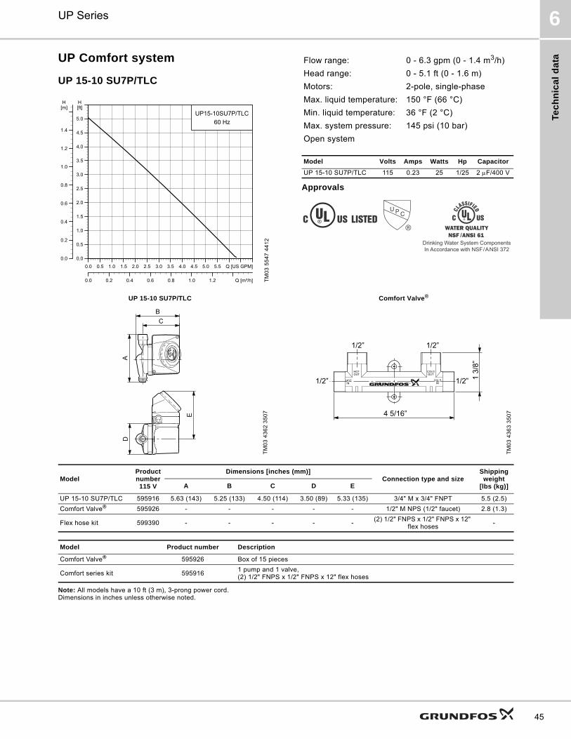
Tec
hn
ica
l d
ata
UP Series 6
45
UP Comfort system
UP 15-10 SU7P/TLC
Approvals
Note: All models have a 10 ft (3 m), 3-prong power cord. Dimensions in inches unless otherwise noted.
TM
03
55
47
44
12
0.0 0.5 1.0 1.5 2.0 2.5 3.0 3.5 4.0 4.5 5.0 5.5 Q [US GPM]0.0
0.5
1.0
1.5
2.0
2.5
3.0
3.5
4.0
4.5
5.0
[ft]H
0.0 0.2 0.4 0.6 0.8 1.0 1.2 Q [m³/h]
0.0
0.2
0.4
0.6
0.8
1.0
1.2
1.4
[m]H
UP15-10SU7P/TLC60 Hz
Flow range: 0 - 6.3 gpm (0 - 1.4 m3/h)
Head range: 0 - 5.1 ft (0 - 1.6 m)
Motors: 2-pole, single-phase
Max. liquid temperature: 150 °F (66 °C)
Min. liquid temperature: 36 °F (2 °C)
Max. system pressure: 145 psi (10 bar)
Open system
Model Volts Amps Watts Hp Capacitor
UP 15-10 SU7P/TLC 115 0.23 25 1/25 2 F/400 V
Drinking Water System ComponentsIn Accordance with NSF/ANSI 372
UP 15-10 SU7P/TLC Comfort Valve®
TM
03
43
62
35
07
TM
03
43
63
35
07
1 3/
8”
4 5/16”
1/2” 1/2”
1/2” 1/2”
ModelProduct number115 V
Dimensions [inches (mm)]Connection type and size
Shipping weight
[lbs (kg)]A B C D E
UP 15-10 SU7P/TLC 595916 5.63 (143) 5.25 (133) 4.50 (114) 3.50 (89) 5.33 (135) 3/4" M x 3/4" FNPT 5.5 (2.5)
Comfort Valve® 595926 - - - - - 1/2" M NPS (1/2" faucet) 2.8 (1.3)
Flex hose kit 599390 - - - - -(2) 1/2" FNPS x 1/2" FNPS x 12"
flex hoses-
Model Product number Description
Comfort Valve® 595926 Box of 15 pieces
Comfort series kit 5959161 pump and 1 valve,(2) 1/2" FNPS x 1/2" FNPS x 12" flex hoses
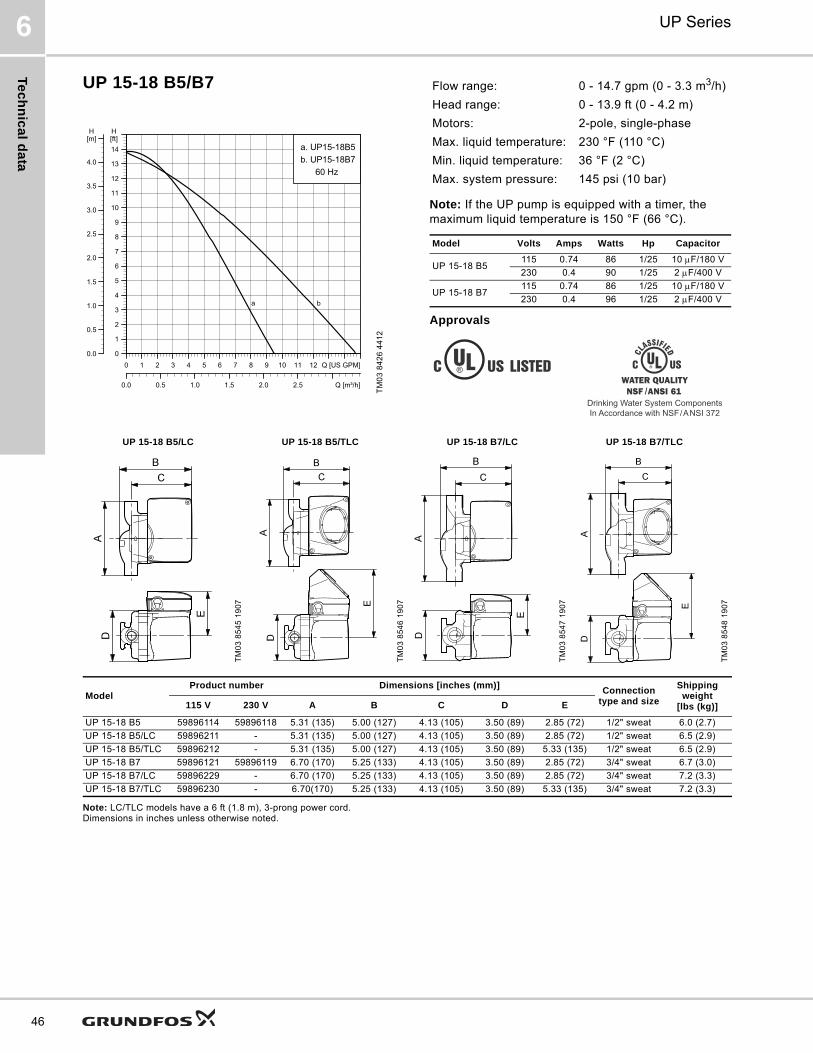
Te
ch
nic
al d
ata
UP Series6
46
UP 15-18 B5/B7
Note: If the UP pump is equipped with a timer, the maximum liquid temperature is 150 °F (66 °C).
Approvals
Note: LC/TLC models have a 6 ft (1.8 m), 3-prong power cord. Dimensions in inches unless otherwise noted.
TM
03
84
26
44
12
0 1 2 3 4 5 6 7 8 9 10 11 12 Q [US GPM]0
1
2
3
4
5
6
7
8
9
10
11
12
13
14[ft]H
0.0 0.5 1.0 1.5 2.0 2.5 Q [m³/h]
0.0
0.5
1.0
1.5
2.0
2.5
3.0
3.5
4.0
[m]H
a. UP15-18B5b. UP15-18B7
60 Hz
a b
Flow range: 0 - 14.7 gpm (0 - 3.3 m3/h)
Head range: 0 - 13.9 ft (0 - 4.2 m)
Motors: 2-pole, single-phase
Max. liquid temperature: 230 °F (110 °C)
Min. liquid temperature: 36 °F (2 °C)
Max. system pressure: 145 psi (10 bar)
Model Volts Amps Watts Hp Capacitor
UP 15-18 B5115 0.74 86 1/25 10 F/180 V
230 0.4 90 1/25 2 F/400 V
UP 15-18 B7115 0.74 86 1/25 10 F/180 V
230 0.4 96 1/25 2 F/400 V
Drinking Water System ComponentsIn Accordance with NSF/ANSI 372
UP 15-18 B5/LC UP 15-18 B5/TLC UP 15-18 B7/LC UP 15-18 B7/TLC
TM
03
85
45
19
07
TM
03
85
46
19
07
TM
03
85
47
19
07
TM
03
85
48
19
07
ModelProduct number Dimensions [inches (mm)]
Connection type and size
Shipping weight
[lbs (kg)]115 V 230 V A B C D E
UP 15-18 B5 59896114 59896118 5.31 (135) 5.00 (127) 4.13 (105) 3.50 (89) 2.85 (72) 1/2" sweat 6.0 (2.7)
UP 15-18 B5/LC 59896211 - 5.31 (135) 5.00 (127) 4.13 (105) 3.50 (89) 2.85 (72) 1/2" sweat 6.5 (2.9)
UP 15-18 B5/TLC 59896212 - 5.31 (135) 5.00 (127) 4.13 (105) 3.50 (89) 5.33 (135) 1/2" sweat 6.5 (2.9)
UP 15-18 B7 59896121 59896119 6.70 (170) 5.25 (133) 4.13 (105) 3.50 (89) 2.85 (72) 3/4" sweat 6.7 (3.0)
UP 15-18 B7/LC 59896229 - 6.70 (170) 5.25 (133) 4.13 (105) 3.50 (89) 2.85 (72) 3/4" sweat 7.2 (3.3)
UP 15-18 B7/TLC 59896230 - 6.70(170) 5.25 (133) 4.13 (105) 3.50 (89) 5.33 (135) 3/4" sweat 7.2 (3.3)

Tec
hn
ica
l d
ata
UP Series 6
47
UP 15-18 BUC5/BUC7
Approvals
Note: Dimensions in inches unless otherwise noted.
TM
03
84
28
44
12
0 1 2 3 4 5 6 7 8 9 10 11 12 13 Q [US GPM]0
2
4
6
8
10
12
14
16
[ft]H
0.0 0.5 1.0 1.5 2.0 2.5 3.0 Q [m³/h]
0
1
2
3
4
5
[m]H
a. UP15-18BUC5b. UP15-18BUC7
60 Hz
a
b
Flow range: 0 - 14.7 gpm (0 - 3.3 m3/h)
Head range: 0 - 14.5 ft (4.4 m)
Motors: 2-pole, single-phase
Max. liquid temperature: 230 °F (110 °C)
Min. liquid temperature: 36 °F (2 °C)
Max. system pressure: 145 psi (10 bar)
Model Volts Amps Watts Hp Capacitor
UP 15-18 BUC5 115 0.74 86 1/25 10 F/180 V
UP 15-18 BUC7 115 0.74 86 1/25 10 F/180 V
Drinking Water System ComponentsIn Accordance with NSF/ANSI 372
UP 15-18 BUC5 UP 15-18 BUC7
TM
03
85
49
19
07
TM
03
87
53
24
07
ModelProduct number115 V
Dimensions [inches (mm)]Connection type
and sizeShipping weight
[lbs (kg)]A B C D E
UP 15-18 BUC5 59896123 5.31 (135) 5.00 (127) 4.13 (105) 3.50 (89) 2.85 (72) 1/2" sweat 7.3 (3.3)
UP 15-18 BUC7 59896124 6.70 (170) 5.25 (133) 4.13 (105) 3.50 (89) 2.85 (72) 3/4" sweat 8.0 (3.6)
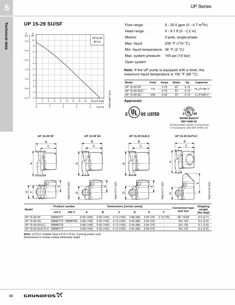
Te
ch
nic
al d
ata
UP Series6
48
UP 15-29 SU/SF
Note: If the UP pump is equipped with a timer, the maximum liquid temperature is 150 °F (66 °C).
Approvals
Note: LC/TLC models have a 6 ft (1.8 m), 3-prong power cord. Dimensions in inches unless otherwise noted.
TM
03
88
47
44
12
0 2 4 6 8 10 12 14 16 18Q [US GPM]0
1
2
3
4
5
6
7
8
9
10
[ft]H
0 1 2 3 4 Q [m³/h]
0.0
0.5
1.0
1.5
2.0
2.5
3.0
[m]H
UP15-2960 Hz
Flow range: 0 - 20.5 gpm (0 - 4.7 m3/h)
Head range: 0 - 9.7 ft (0 - 2.2 m)
Motors: 2-pole, single-phase
Max. liquid 230 °F (110 °C)
Min. liquid temperature: 36 °F (2 °C)
Max. system pressure: 145 psi (10 bar)
Open system
Model Volts Amps Watts Hp Capacitor
UP 15-29 SF115
0.75 87 0.1210 F/180 V
UP 15-29 SUC 0.75 87 0.12
UP 15-29 SU 230 0.42 97 0.15 2 F/400 V
Drinking Water System ComponentsIn Accordance with NSF/ANSI 372
UP 15-29 SF UP 15-29 SU UP 15-29 SU/LC UP 15-29 SU/TLC
TM
03
87
76
25
07
TM
03
87
77
25
07
TM
03
87
77
25
07
TM
03
87
78
25
07
ModelProduct number Dimensions [inches (mm)]
Connection type and size
Shipping weight
[lbs (kg)]115 V 230 V A B C D E F
UP 15-29 SF 59896771 - 6.50 (165) 5.50 (140) 4.13 (105) 3.88 (98) 2.94 (75) 3.13 (79) GF 15/26 6.0 (2.7)
UP 15-29 SU 59896775 59896784 5.88 (149) 5.50 (140) 4.13 (105) 3.44 (88) 2.94 (75) - GU 125 5.4 (2.5)
UP 15-29 SU/LC 59896776 - 5.88 (149) 5.50 (140) 4.13 (105) 3.44 (88) 2.94 (75) - GU 125 5.7 (2.6)
UP 15-29 SUC/TLC 59896777 - 5.88 (149) 5.50 (140) 4.13 (105) 3.44 (88) 2.94 (75) - GU 125 6.2 (2.8)
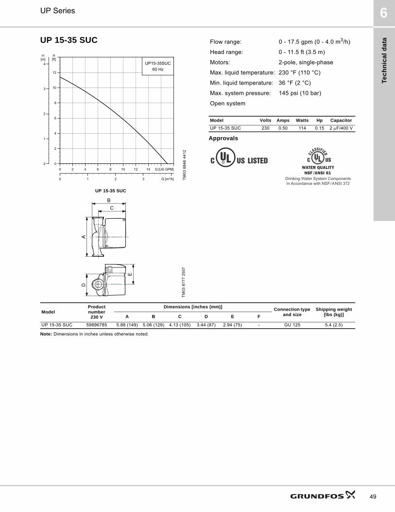
Tec
hn
ica
l d
ata
UP Series 6
49
UP 15-35 SUC
Approvals
Note: Dimensions in inches unless otherwise noted.
TM
03
88
46
44
12
UP 15-35 SUC
TM
03
87
77
25
07
0 2 4 6 8 10 12 14 Q [US GPM]0
2
4
6
8
10
12
[ft]H
0 1 2 3 Q [m³/h]
0
1
2
3
4[m]H
UP15-35SUC60 Hz
Flow range: 0 - 17.5 gpm (0 - 4.0 m3/h)
Head range: 0 - 11.5 ft (3.5 m)
Motors: 2-pole, single-phase
Max. liquid temperature: 230 °F (110 °C)
Min. liquid temperature: 36 °F (2 °C)
Max. system pressure: 145 psi (10 bar)
Open system
Model Volts Amps Watts Hp Capacitor
UP 15-35 SUC 230 0.50 114 0.15 2 F/400 V
Drinking Water System ComponentsIn Accordance with NSF/ANSI 372
ModelProduct number230 V
Dimensions [inches (mm)]Connection type
and sizeShipping weight
[lbs (kg)]A B C D E F
UP 15-35 SUC 59896785 5.88 (149) 5.06 (129) 4.13 (105) 3.44 (87) 2.94 (75) - GU 125 5.4 (2.5)
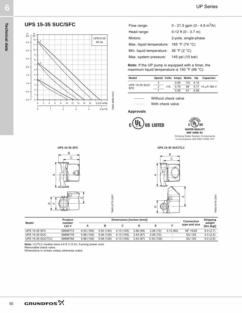
Te
ch
nic
al d
ata
UP Series6
50
UPS 15-35 SUC/SFC
Note: If the UP pump is equipped with a timer, the maximum liquid temperature is 150 °F (66 °C).
Approvals
Note: LC/TLC models have a 6 ft (1.8 m), 3-prong power cord. Removable check valve. Dimensions in inches unless otherwise noted.
TM
03
88
50
44
12
0 2 4 6 8 10 12 14 16 18 Q [US GPM]0
1
2
3
4
5
6
7
8
9
10
11
12
[ft]H
0 1 2 3 4 Q [m³/h]
0.0
0.5
1.0
1.5
2.0
2.5
3.0
3.5
[m]H
UPS15-3560 Hz3
2
1
Flow range: 0 - 21.5 gpm (0 - 4.9 m3/h)
Head range: 0-12 ft (0 - 3.7 m)
Motors: 2-pole, single-phase
Max. liquid temperature: 165 °F (74 °C)
Min. liquid temperature: 36 °F (2 °C)
Max. system pressure: 145 psi (10 bar)
Model Speed Volts Amps Watts Hp Capacitor
UPS 15-35 SUC/ SFC
3
115
0.95 110 0.15
10 F/180 V2 0.75 84 0.11
1 0.55 61 0.08
Without check valve
With check valve
Drinking Water System ComponentsIn Accordance with NSF/ANSI 372
UPS 15-35 SFC UPS 15-35 SUC/TLC
TM
03
87
79
25
07
TM
03
87
78
25
07
ModelProduct number115 V
Dimensions [inches (mm)]Connection
type and size
Shipping weight
[lbs (kg)]A B C D E F
UPS 15-35 SFC 59896772 6.50 (165) 5.50 (140) 4.13 (105) 3.88 (99) 2.85 (72) 3.13 (80) GF 15/26 6.0 (2.7)
UPS 15-35 SUC 59896778 5.88 (149) 5.06 (129) 4.13 (105) 3.44 (87) 2.85 (72) - GU 125 5.4 (2.5)
UPS 15-35 SUC/TLC 59896780 5.88 (149) 5.06 (129) 4.13 (105) 3.44 (87) 5.33 (135) - GU 125 6.2 (2.8)
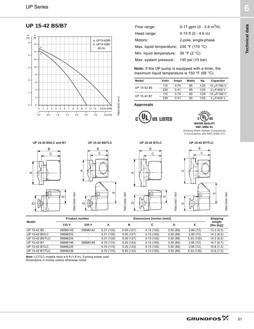
Tec
hn
ica
l d
ata
UP Series 6
51
UP 15-42 B5/B7
Note: If the UP pump is equipped with a timer, the maximum liquid temperature is 150 °F (66 °C).
Approvals
Note: LC/TLC models have a 6 ft (1.8 m), 3-prong power cord. Dimensions in inches unless otherwise noted.
TM
03
84
30
44
12
0 1 2 3 4 5 6 7 8 9 10 11 12 13 Q [US GPM]0
2
4
6
8
10
12
14
16
[ft]H
0.0 0.5 1.0 1.5 2.0 2.5 3.0 Q [m³/h]
0
1
2
3
4
5
[m]H
a. UP15-42B5b. UP15-42B7
60 Hz
a
b
Flow range: 0-17 gpm (0 - 3.9 m3/h)
Head range: 0-15 ft (0 - 4.6 m)
Motors: 2-pole, single-phase
Max. liquid temperature: 230 °F (110 °C)
Min. liquid temperature: 36 °F (2 °C)
Max. system pressure: 145 psi (10 bar)
Model Volts Amps Watts Hp Capacitor
UP 15-42 B5115 0.74 85 1/25 10 F/180 V
230 0.41 95 1/25 2 F/400 V
UP 15-42 B7115 0.74 85 1/25 10 F/180 V
230 0.41 95 1/25 2 F/400 V
Drinking Water System ComponentsIn Accordance with NSF/ANSI 372
UP 15-42 B5/LC and B7 UP 15-42 B5/TLC UP 15-42 B7/LC UP 15-42 B7/TLC
TM
03
85
45
19
07
TM
03
85
46
19
07
TM
03
85
47
19
07
TM
03
85
48
19
07
ModelProduct number Dimensions [inches (mm)] Shipping
weight[lbs (kg)]115 V 230 V A B C D E
UP 15-42 B5 59896145 59896142 5.31 (135) 5.00 (127) 4.13 (105) 3.50 (89) 2.85 (72) 13.2 (6.0)
UP 15-42 B5/LC 59896233 - 5.31 (135) 5.00 (127) 4.13 (105) 3.50 (89) 2.85 (72) 14.3 (6.5)
UP 15-42 B5/TLC 59896234 - 5.31 (135) 5.00 (127) 4.13 (105) 3.50 (89) 5.33 (135) 14.3 (6.5)
UP 15-42 B7 59896146 59896149 6.70 (170) 5.25 (133) 4.13 (105) 3.50 (89) 2.85 (72) 14.7 (6.7)
UP 15-42 B7/LC 59896235 - 6.70 (170) 5.25 (133) 4.13 (105) 3.50 (89) 2.85 (72) 15.8 (7.2)
UP 15-42 B7/TLC 59896236 - 6.70 (170) 5.25 (133) 4.13 (105) 3.50 (89) 5.33 (135) 15.8 (7.2)
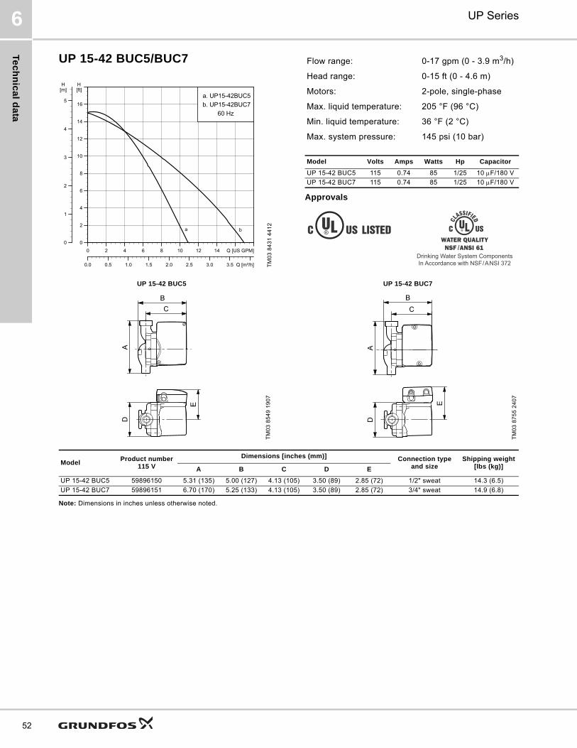
Te
ch
nic
al d
ata
UP Series6
52
UP 15-42 BUC5/BUC7
Approvals
Note: Dimensions in inches unless otherwise noted.
TM
03
84
31
44
12
0 2 4 6 8 10 12 14 Q [US GPM]0
2
4
6
8
10
12
14
16
[ft]H
0.0 0.5 1.0 1.5 2.0 2.5 3.0 3.5 Q [m³/h]
0
1
2
3
4
5
[m]H
a. UP15-42BUC5b. UP15-42BUC7
60 Hz
a b
Flow range: 0-17 gpm (0 - 3.9 m3/h)
Head range: 0-15 ft (0 - 4.6 m)
Motors: 2-pole, single-phase
Max. liquid temperature: 205 °F (96 °C)
Min. liquid temperature: 36 °F (2 °C)
Max. system pressure: 145 psi (10 bar)
Model Volts Amps Watts Hp Capacitor
UP 15-42 BUC5 115 0.74 85 1/25 10 F/180 V
UP 15-42 BUC7 115 0.74 85 1/25 10 F/180 V
Drinking Water System ComponentsIn Accordance with NSF/ANSI 372
UP 15-42 BUC5 UP 15-42 BUC7
TM
03
85
49
19
07
TM
03
87
55
24
07
ModelProduct number
115 V
Dimensions [inches (mm)] Connection type and size
Shipping weight[lbs (kg)]A B C D E
UP 15-42 BUC5 59896150 5.31 (135) 5.00 (127) 4.13 (105) 3.50 (89) 2.85 (72) 1/2" sweat 14.3 (6.5)
UP 15-42 BUC7 59896151 6.70 (170) 5.25 (133) 4.13 (105) 3.50 (89) 2.85 (72) 3/4" sweat 14.9 (6.8)
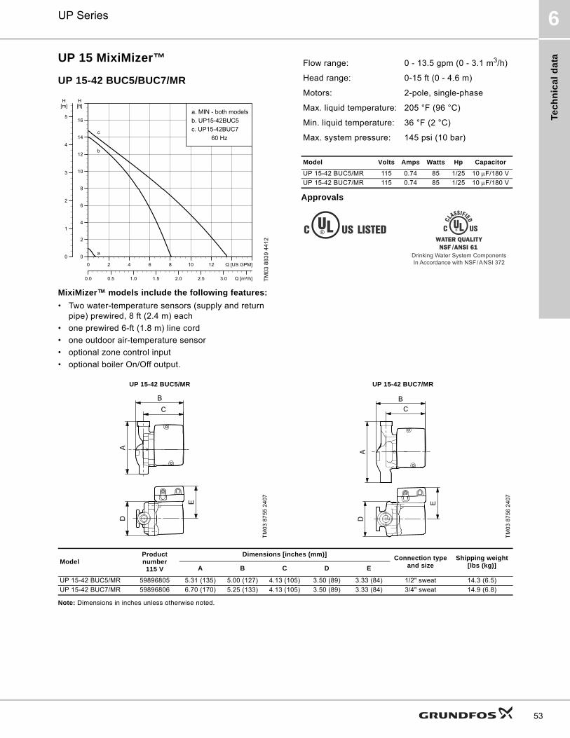
Tec
hn
ica
l d
ata
UP Series 6
53
UP 15 MixiMizer™
UP 15-42 BUC5/BUC7/MR
Approvals
MixiMizer™ models include the following features:
• Two water-temperature sensors (supply and return pipe) prewired, 8 ft (2.4 m) each
• one prewired 6-ft (1.8 m) line cord
• one outdoor air-temperature sensor
• optional zone control input
• optional boiler On/Off output.
Note: Dimensions in inches unless otherwise noted.
TM
03
88
39
44
12
0 2 4 6 8 10 12 Q [US GPM]0
2
4
6
8
10
12
14
16
[ft]H
0.0 0.5 1.0 1.5 2.0 2.5 3.0 Q [m³/h]
0
1
2
3
4
5
[m]H
a. MIN - both modelsb. UP15-42BUC5c. UP15-42BUC7
60 Hzc
b
a
Flow range: 0 - 13.5 gpm (0 - 3.1 m3/h)
Head range: 0-15 ft (0 - 4.6 m)
Motors: 2-pole, single-phase
Max. liquid temperature: 205 °F (96 °C)
Min. liquid temperature: 36 °F (2 °C)
Max. system pressure: 145 psi (10 bar)
Model Volts Amps Watts Hp Capacitor
UP 15-42 BUC5/MR 115 0.74 85 1/25 10 F/180 V
UP 15-42 BUC7/MR 115 0.74 85 1/25 10 F/180 V
Drinking Water System ComponentsIn Accordance with NSF/ANSI 372
UP 15-42 BUC5/MR UP 15-42 BUC7/MR
TM
03
87
55
24
07
TM
03
87
56
24
07
ModelProduct number115 V
Dimensions [inches (mm)]Connection type
and sizeShipping weight
[lbs (kg)]A B C D E
UP 15-42 BUC5/MR 59896805 5.31 (135) 5.00 (127) 4.13 (105) 3.50 (89) 3.33 (84) 1/2" sweat 14.3 (6.5)
UP 15-42 BUC7/MR 59896806 6.70 (170) 5.25 (133) 4.13 (105) 3.50 (89) 3.33 (84) 3/4" sweat 14.9 (6.8)

Te
ch
nic
al d
ata
UP Series6
54
UP 15-42 F/FR
Approvals
Note: Dimensions in inches unless otherwise noted.
TM
03
55
33
44
12
0 2 4 6 8 10 12 14 Q [US GPM]0
2
4
6
8
10
12
14
16
[ft]H
0.0 0.5 1.0 1.5 2.0 2.5 3.0 3.5 Q [m³/h]
0
1
2
3
4
5
[m]H
UP15-42F/FR60 Hz
Flow range: 0-17 gpm (0 - 3.9 m3/h)
Head range: 0-15 ft (0 - 4.6 m)
Motors: 2-pole, single-phase
Max. liquid temperature: 230 °F (110 °C)
Min. liquid temperature: 36 °F (2 °C)
Max. system pressure: 145 psi (10 bar)
Closed system
Model Volts Amps Watts Hp Capacitor
UP 15-42 F/FR115 0.74 85 1/25 10 F/180 V
230 0.43 95 1/25 2 F/400 V
UP 15-42 F UP 15-42 FRT
M0
3 8
52
6 1
90
7
TM
03
85
27
19
07
ModelProduct number Dimensions [inches (mm)]
Connection type and size
Shipping weight
[lbs (kg)]115 V 230 V A B C D E F
UP 15-42 F 59896155 59896173 6.50 (165) 5.25 (133) 4.00 (102) 4.19 (106) 3.25 (83) 3.16 (80) GF 15/26 flange(2) 1/2" dia. bolt holes
7.3 (3.3)UP 15-42 FR 59896167 59896274 6.50 (165) 5.94 (151) 4.00 (102) 3.75 (95) 3.25 (83) 3.16 (80)

Tec
hn
ica
l d
ata
UP Series 6
55
UPS 15-42 F
Approvals
Note: Dimensions in inches unless otherwise noted.
TM
03
55
74
44
12
0 2 4 6 8 10 12 14 Q [US GPM]0
2
4
6
8
10
12
14
16
[ft]H
0.0 0.5 1.0 1.5 2.0 2.5 3.0 3.5 Q [m³/h]
0
1
2
3
4
5
[m]H
UPS15-42F60 Hz
3
2
1
Flow range: 0 - 17.5 gpm (0 - 4.0 m3/
Head range: 0 - 15.5 ft (0 - 4.7 m)
Motors: 2-pole, single-phase
Max. liquid temperature: 230 °F (110 °C)
Min. liquid temperature: 36 °F (2 °C)
Max. system pressure: 145 psi (10 bar)
Model Speed Volts Amps Watts Hp Capacitor
UPS 15-42 F
3
230
0.41 92
1/25 2 F/400 V2 0.19 40
1 0.14 30
UPS 15-42 F
TM
03
87
57
24
07
ModelProduct number Dimensions [inches (mm)] Connection type and
sizeShipping weight
[lbs (kg)]115 V 230 V A B C D E F
UPS 15-42 F - 59896180 6.5 (165) 5.25 (133) 4.00 (102) 4.19 (106) 3.25 (83) 3.16 (80)GF 15/26 flange
(2) 1/2" dia. bolt holes7.3 (3.3)
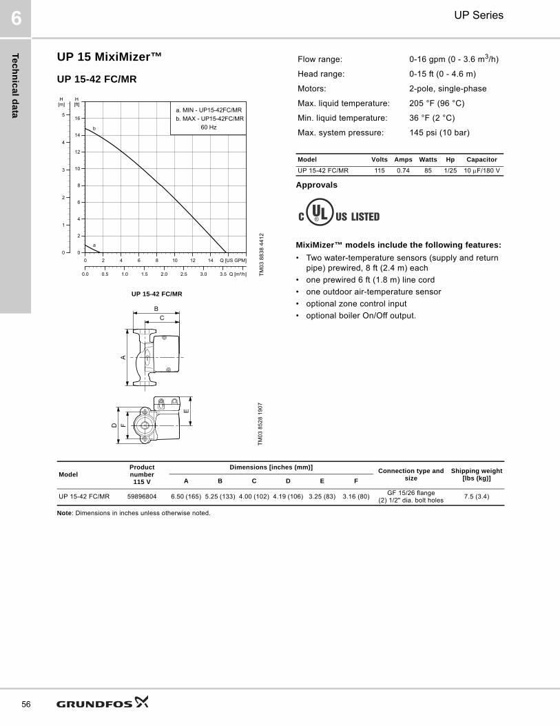
Te
ch
nic
al d
ata
UP Series6
56
UP 15 MixiMizer™
UP 15-42 FC/MR
Approvals
MixiMizer™ models include the following features:
• Two water-temperature sensors (supply and return pipe) prewired, 8 ft (2.4 m) each
• one prewired 6 ft (1.8 m) line cord
• one outdoor air-temperature sensor
• optional zone control input
• optional boiler On/Off output.
Note: Dimensions in inches unless otherwise noted.
TM
03
88
38
44
12
UP 15-42 FC/MR
TM
03
85
28
19
07
0 2 4 6 8 10 12 14 Q [US GPM]0
2
4
6
8
10
12
14
16
[ft]H
0.0 0.5 1.0 1.5 2.0 2.5 3.0 3.5 Q [m³/h]
0
1
2
3
4
5
[m]H
a. MIN - UP15-42FC/MRb. MAX - UP15-42FC/MR
60 Hzb
a
Flow range: 0-16 gpm (0 - 3.6 m3/h)
Head range: 0-15 ft (0 - 4.6 m)
Motors: 2-pole, single-phase
Max. liquid temperature: 205 °F (96 °C)
Min. liquid temperature: 36 °F (2 °C)
Max. system pressure: 145 psi (10 bar)
Model Volts Amps Watts Hp Capacitor
UP 15-42 FC/MR 115 0.74 85 1/25 10 F/180 V
ModelProduct number115 V
Dimensions [inches (mm)]Connection type and
sizeShipping weight
[lbs (kg)]A B C D E F
UP 15-42 FC/MR 59896804 6.50 (165) 5.25 (133) 4.00 (102) 4.19 (106) 3.25 (83) 3.16 (80)GF 15/26 flange
(2) 1/2" dia. bolt holes7.5 (3.4)
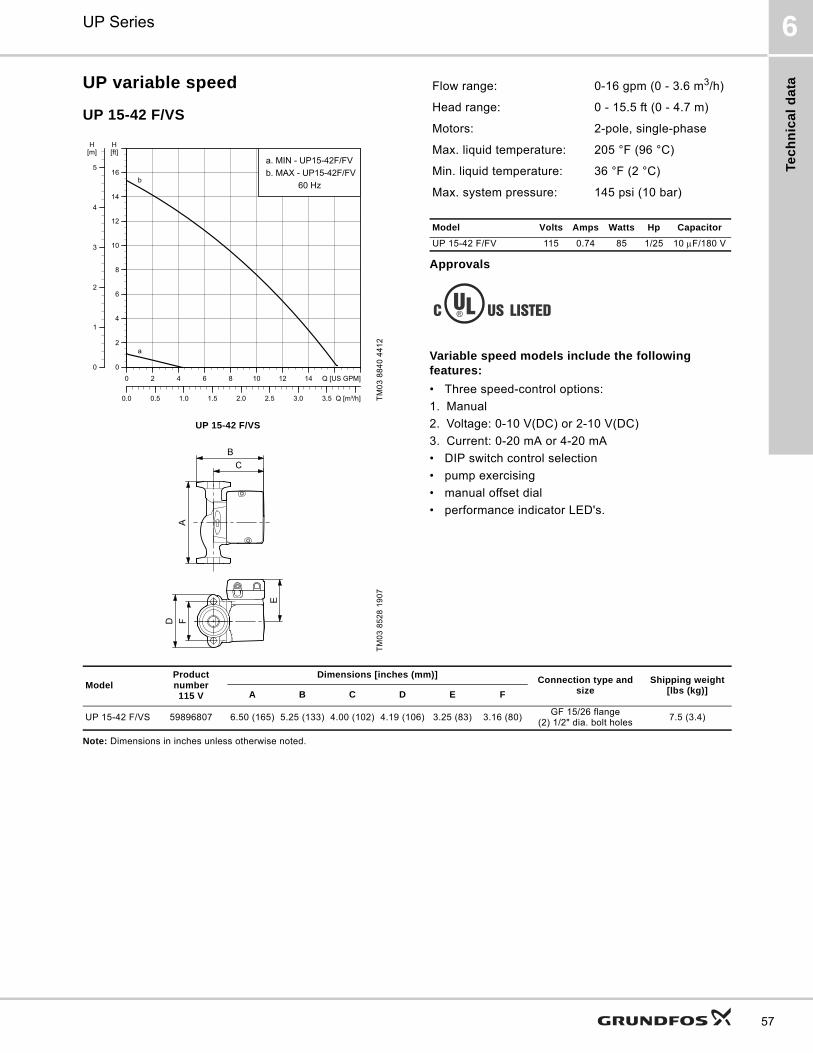
Tec
hn
ica
l d
ata
UP Series 6
57
UP variable speed
UP 15-42 F/VS
Approvals
Variable speed models include the following features:
• Three speed-control options:
1. Manual
2. Voltage: 0-10 V(DC) or 2-10 V(DC)
3. Current: 0-20 mA or 4-20 mA
• DIP switch control selection
• pump exercising
• manual offset dial
• performance indicator LED's.
Note: Dimensions in inches unless otherwise noted.
TM
03
88
40
44
12
UP 15-42 F/VS
TM
03
85
28
19
07
0 2 4 6 8 10 12 14 Q [US GPM]0
2
4
6
8
10
12
14
16
[ft]H
0.0 0.5 1.0 1.5 2.0 2.5 3.0 3.5 Q [m³/h]
0
1
2
3
4
5
[m]H
a. MIN - UP15-42F/FVb. MAX - UP15-42F/FV
60 Hzb
a
Flow range: 0-16 gpm (0 - 3.6 m3/h)
Head range: 0 - 15.5 ft (0 - 4.7 m)
Motors: 2-pole, single-phase
Max. liquid temperature: 205 °F (96 °C)
Min. liquid temperature: 36 °F (2 °C)
Max. system pressure: 145 psi (10 bar)
Model Volts Amps Watts Hp Capacitor
UP 15-42 F/FV 115 0.74 85 1/25 10 F/180 V
ModelProduct number115 V
Dimensions [inches (mm)]Connection type and
sizeShipping weight
[lbs (kg)]A B C D E F
UP 15-42 F/VS 59896807 6.50 (165) 5.25 (133) 4.00 (102) 4.19 (106) 3.25 (83) 3.16 (80)GF 15/26 flange
(2) 1/2" dia. bolt holes7.5 (3.4)

Te
ch
nic
al d
ata
UP Series6
58
UP 15-55 SUC
Approvals
Note: Dimensions in inches unless otherwise noted.
TM
03
88
45
44
12
0 2 4 6 8 10 12 14 16 18Q [US GPM]0
2
4
6
8
10
12
14
16
18
[ft]H
0.0 0.5 1.0 1.5 2.0 2.5 3.0 3.5 4.0 Q [m³/h]
0
1
2
3
4
5
[m]H
UP15-55SUC60 Hz
Flow range: 0 - 21.5 gpm (0 - 4.9 m3/h)
Head range: 0-17 ft (0 - 5.2 m)
Motors: 2-pole, single-phase
Max. liquid temperature: 230 °F (110 °C)
Min. liquid temperature: 36 °F (2 °C)
Max. system pressure: 145 psi (10 bar)
Closed system
Model Volts Amps Watts Hp Capacitor
UP 15-55 SUC 230 0.42 97 0.13 2 F/400 V
Drinking Water System ComponentsIn Accordance with NSF/ANSI 372
UP 15-55 SUC
TM
03
87
77
25
07
ModelProduct number Dimensions [inches (mm)]
Connection type and size
Shipping weight
[lbs (kg)]115 V 230 V A B C D E F
UP 15-55 SUC - 59896786 5.88 (149) 5.06 (129) 4.13 (105) 3.44 (87) 2.94 (75) 5.88 (149) GU 125 5.4 (2.5)
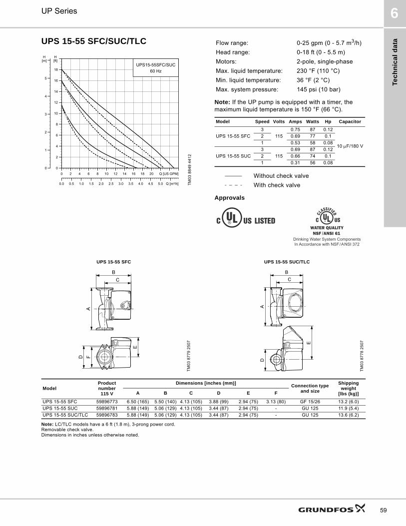
Tec
hn
ica
l d
ata
UP Series 6
59
UPS 15-55 SFC/SUC/TLC
Note: If the UP pump is equipped with a timer, the maximum liquid temperature is 150 °F (66 °C).
Approvals
Note: LC/TLC models have a 6 ft (1.8 m), 3-prong power cord. Removable check valve. Dimensions in inches unless otherwise noted.
TM
03
88
49
44
12
0 2 4 6 8 10 12 14 16 18 20 Q [US GPM]0
2
4
6
8
10
12
14
16
18
[ft]H
0.0 0.5 1.0 1.5 2.0 2.5 3.0 3.5 4.0 4.5 5.0 Q [m³/h]
0
1
2
3
4
5
[m]H
UPS15-55SFC/SUC60 Hz
3
2
1
Flow range: 0-25 gpm (0 - 5.7 m3/h)
Head range: 0-18 ft (0 - 5.5 m)
Motors: 2-pole, single-phase
Max. liquid temperature: 230 °F (110 °C)
Min. liquid temperature: 36 °F (2 °C)
Max. system pressure: 145 psi (10 bar)
Model Speed Volts Amps Watts Hp Capacitor
UPS 15-55 SFC
3
115
0.75 87 0.12
10 F/180 V
2 0.69 77 0.1
1 0.53 58 0.08
UPS 15-55 SUC
3
115
0.69 87 0.12
2 0.66 74 0.1
1 0.31 56 0.08
Without check valve
With check valve
Drinking Water System ComponentsIn Accordance with NSF/ANSI 372
UPS 15-55 SFC UPS 15-55 SUC/TLC
TM
03
87
79
25
07
TM
03
87
78
25
07
ModelProduct number115 V
Dimensions [inches (mm)]Connection type
and size
Shipping weight
[lbs (kg)]A B C D E F
UPS 15-55 SFC 59896773 6.50 (165) 5.50 (140) 4.13 (105) 3.88 (99) 2.94 (75) 3.13 (80) GF 15/26 13.2 (6.0)
UPS 15-55 SUC 59896781 5.88 (149) 5.06 (129) 4.13 (105) 3.44 (87) 2.94 (75) - GU 125 11.9 (5.4)
UPS 15-55 SUC/TLC 59896783 5.88 (149) 5.06 (129) 4.13 (105) 3.44 (87) 2.94 (75) - GU 125 13.6 (6.2)
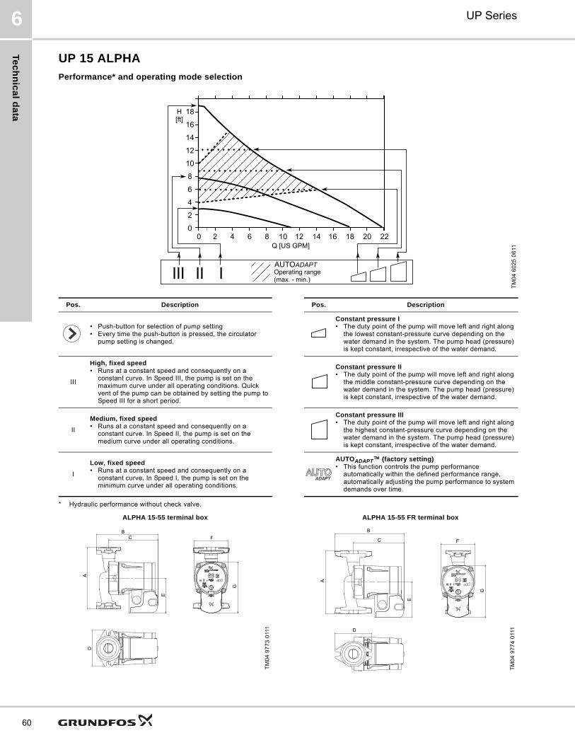
Te
ch
nic
al d
ata
UP Series6
60
UP 15 ALPHA
Performance* and operating mode selection
* Hydraulic performance without check valve.
TM
04
60
25
06
11
Pos. Description Pos. Description
• Push-button for selection of pump setting• Every time the push-button is pressed, the circulator
pump setting is changed.
Constant pressure I• The duty point of the pump will move left and right along
the lowest constant-pressure curve depending on the water demand in the system. The pump head (pressure) is kept constant, irrespective of the water demand.
III
High, fixed speed• Runs at a constant speed and consequently on a
constant curve. In Speed III, the pump is set on the maximum curve under all operating conditions. Quick vent of the pump can be obtained by setting the pump to Speed III for a short period.
Constant pressure II• The duty point of the pump will move left and right along
the middle constant-pressure curve depending on the water demand in the system. The pump head (pressure) is kept constant, irrespective of the water demand.
II
Medium, fixed speed• Runs at a constant speed and consequently on a
constant curve. In Speed II, the pump is set on the medium curve under all operating conditions.
Constant pressure III• The duty point of the pump will move left and right along
the highest constant-pressure curve depending on the water demand in the system. The pump head (pressure) is kept constant, irrespective of the water demand.
I
Low, fixed speed• Runs at a constant speed and consequently on a
constant curve. In Speed I, the pump is set on the minimum curve under all operating conditions.
AUTOADAPT™ (factory setting)• This function controls the pump performance
automatically within the defined performance range, automatically adjusting the pump performance to system demands over time.
ALPHA 15-55 terminal box
TM
04
97
73
011
1
BC
A
E
G
F
D
ALPHA 15-55 FR terminal boxT
M0
4 9
77
4 0
111
B
C
A
E
F
G
D

Tec
hn
ica
l d
ata
UP Series 6
61
UP 15 ALPHA
Approximate power usage
Approvals
Note: Dimensions in inches unless otherwise noted. LC models have a 6 ft (1.8 m), 3-prong power cord.
ALPHA 15-55 line cord
TM
04
60
12
47
09
ALPHA 15-55 FR line cord
TM
04
60
13
47
09
G
BC
E
AD
F
A
BC
E
D
F
G
Flow range: 0 - 21.5 gpm (0 - 4.9 m3/h)Head range: 0-17 ft (0 - 5.2 m)Motors: 2-pole, single-phaseMax. liquid temperature: 230 °F (110 °C)Min. liquid temperature: 36 °F (2 °C)Max. system pressure: 150 psi (10 bar)Closed (F, FR) and open systems (SF)
Model Volts Amps Watts Hp Capacitor
ALPHA 15-55 115 0.65 5 to 45 0.06 -
Speed settingMin.[W]
Max.[W]
High, fixed speed III 39 45
Medium, fixed speed II 15 30
Low, fixed speed I 5 8
Constant pressure 8 45
Constant pressure 14 45
Constant pressure 22 45
AUTOADAPT™ 5 45
Canadian EMC Standard: ICES-003 This Class B digital apparatus complies
with Canadian ICES-003.
Drinking Water System ComponentsIn Accordance with NSF/ANSI 372
ModelProduct number115 V
Dimensions [inches (mm)]Connection type and
size
Shipping weight
[lbs (kg)]A B C D E F G
ALPHA 15-55 F 59896877 6.50 (165) 6.50 (165) 5.25 (133) 3.82 (97) 3.69 (94) 3.56 (90) 5.38 (137)GF 15/26
(2) 1/2" dia. bolt holes
7.2 (15.8)
ALPHA 15-55 FR 59896878 6.50 (165) 7.19 (183) 5.25 (133) 3.82 (97) 3.69 (94) 3.56 (90) 5.38 (137) 7.1 (15.6)
ALPHA 15-55 SF 59896879 6.50 (165) 6.50 (165) 5.25 (133) 3.82 (97) 3.69 (94) 3.56 (90) 5.38 (137) 6.1 (13.4)
ALPHA 15-55 F/LC 59896832 6.50 (165) 6.50 (165) 4.94 (125) 4.00 (102) 2.50 (64) 3.44 (87) 4.13 (105)GF 15/26
(2) 1/2" dia. bolt holes
7.5 (16.5)
ALPHA 15-55 FR/LC 59896833 6.50 (165) 7.00 (178) 4.94 (125) 4.00 (102) 2.50 (64) 3.44 (87) 4.13 (105) 7.3 (16.1)
ALPHA 15-55 SF/LC 59896834 6.50 (165) 6.50 (165) 4.94 (125) 4.00 (102) 2.50 (64) 3.44 (87) 4.13 (105) 6.3 (13.8)
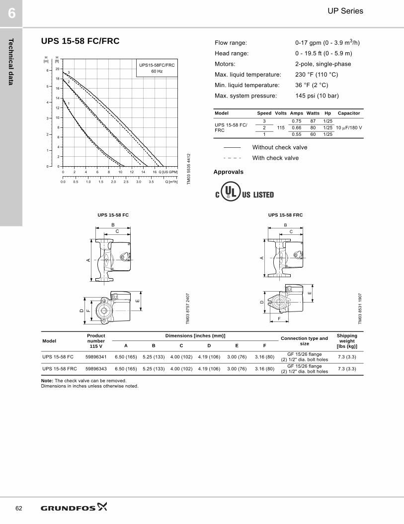
Te
ch
nic
al d
ata
UP Series6
62
UPS 15-58 FC/FRC
Approvals
Note: The check valve can be removed. Dimensions in inches unless otherwise noted.
TM
03
55
35
44
12
0 2 4 6 8 10 12 14 16 Q [US GPM]
0
2
4
6
8
10
12
14
16
18
20
[ft]H
0.0 0.5 1.0 1.5 2.0 2.5 3.0 3.5 Q [m³/h]
0
1
2
3
4
5
6
[m]H
UPS15-58FC/FRC
60 Hz
1
2
3
Flow range: 0-17 gpm (0 - 3.9 m3/h)
Head range: 0 - 19.5 ft (0 - 5.9 m)
Motors: 2-pole, single-phase
Max. liquid temperature: 230 °F (110 °C)
Min. liquid temperature: 36 °F (2 °C)
Max. system pressure: 145 psi (10 bar)
Model Speed Volts Amps Watts Hp Capacitor
UPS 15-58 FC/FRC
3
115
0.75 87 1/25
10 F/180 V2 0.66 80 1/25
1 0.55 60 1/25
Without check valve
With check valve
UPS 15-58 FC UPS 15-58 FRC
TM
03
87
57
24
07
TM
03
85
31
19
07
ModelProduct number115 V
Dimensions [inches (mm)]Connection type and
size
Shipping weight
[lbs (kg)]A B C D E F
UPS 15-58 FC 59896341 6.50 (165) 5.25 (133) 4.00 (102) 4.19 (106) 3.00 (76) 3.16 (80)GF 15/26 flange
(2) 1/2" dia. bolt holes7.3 (3.3)
UPS 15-58 FRC 59896343 6.50 (165) 5.25 (133) 4.00 (102) 4.19 (106) 3.00 (76) 3.16 (80)GF 15/26 flange
(2) 1/2" dia. bolt holes7.3 (3.3)
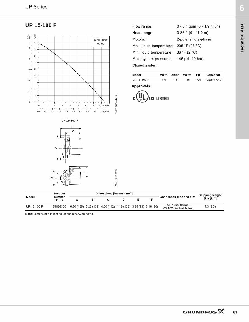
Tec
hn
ica
l d
ata
UP Series 6
63
UP 15-100 F
Approvals
Note: Dimensions in inches unless otherwise noted.
TM
03
55
34
44
12
UP 15-100 F
TM
03
85
30
19
07
0 1 2 3 4 5 6 7 Q [US GPM]
0
4
8
12
16
20
24
28
32
36
[ft]H
0.0 0.2 0.4 0.6 0.8 1.0 1.2 1.4 1.6 Q [m³/h]
0
2
4
6
8
10
[m]H
UP15-100F
60 Hz
Flow range: 0 - 8.4 gpm (0 - 1.9 m3/h)
Head range: 0-36 ft (0 - 11.0 m)
Motors: 2-pole, single-phase
Max. liquid temperature: 205 °F (96 °C)
Min. liquid temperature: 36 °F (2 °C)
Max. system pressure: 145 psi (10 bar)
Closed system
Model Volts Amps Watts Hp Capacitor
UP 15-100 F 115 1.1 135 1/25 12 F/170 V
ModelProduct number115 V
Dimensions [inches (mm)]Connection type and size
Shipping weight[lbs (kg)]A B C D E F
UP 15-100 F 59896300 6.50 (165) 5.25 (133) 4.00 (102) 4.19 (106) 3.25 (83) 3.16 (80)GF 15/26 flange
(2) 1/2" dia. bolt holes7.3 (3.3)

Te
ch
nic
al d
ata
UP Series6
64
UP 26-64 F
Approvals
Note: Dimensions in inches unless otherwise noted.
TM
03
55
36
44
12
0 4 8 12 16 20 24 28 Q [US GPM]
0
2
4
6
8
10
12
14
16
18
20
22
24
26
[ft]H
0 1 2 3 4 5 6 7 Q [m³/h]
0
1
2
3
4
5
6
7
8[m]H
UP26-64F
60 Hz
Flow range: 0-32 gpm (0 - 7.3 m3/h)
Head range: 0 - 24.5 ft (0 - 5.7 m)
Motors: 2-pole, single-phase
Max. liquid temperature: 230 °F (110 °C)
Min. liquid temperature: 36 °F (2 °C)
Max. system pressure: 145 psi (10 bar)
Closed system
Model Volts Amps Watts Hp Capacitor
UP 26-64 F115 1.7 185 1/12 8 F/180 V
230 0.8 175 1/12 2.5 F/380 V
UP 26-64 FT
M0
3 8
77
6 2
50
7
ModelProduct number Dimensions [inches (mm)]
Connection type and size
Shipping weight
[lbs (kg)]115 V 230 V A B C D E F
UP 26-64 F 52722330 52722327 6.50 (165) 6.38 (162) 5.06 (129) 4.13 (105) 3.50 (89) 3.16 (80)GF 15/26 flange
(2) 1/2" dia. bolt holes11 1/4 (5.1)
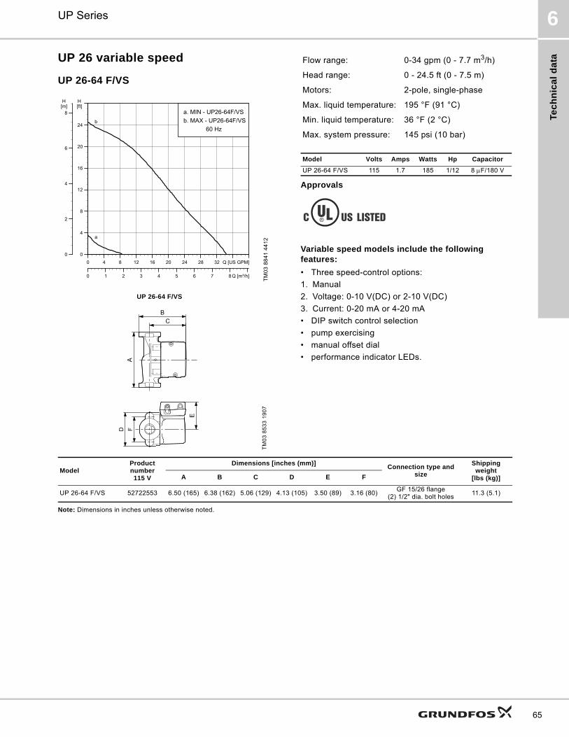
Tec
hn
ica
l d
ata
UP Series 6
65
UP 26 variable speed
UP 26-64 F/VS
Approvals
Variable speed models include the following features:
• Three speed-control options:
1. Manual
2. Voltage: 0-10 V(DC) or 2-10 V(DC)
3. Current: 0-20 mA or 4-20 mA
• DIP switch control selection
• pump exercising
• manual offset dial
• performance indicator LEDs.
Note: Dimensions in inches unless otherwise noted.
TM
03
88
41
44
12
UP 26-64 F/VS
TM
03
85
33
19
07
0 4 8 12 16 20 24 28 32 Q [US GPM]
0
4
8
12
16
20
24
[ft]H
0 1 2 3 4 5 6 7 8 Q [m³/h]
0
2
4
6
8[m]H
a. MIN - UP26-64F/VS
b. MAX - UP26-64F/VS
60 Hzb
a
Flow range: 0-34 gpm (0 - 7.7 m3/h)
Head range: 0 - 24.5 ft (0 - 7.5 m)
Motors: 2-pole, single-phase
Max. liquid temperature: 195 °F (91 °C)
Min. liquid temperature: 36 °F (2 °C)
Max. system pressure: 145 psi (10 bar)
Model Volts Amps Watts Hp Capacitor
UP 26-64 F/VS 115 1.7 185 1/12 8 F/180 V
ModelProduct number115 V
Dimensions [inches (mm)]Connection type and
size
Shipping weight
[lbs (kg)]A B C D E F
UP 26-64 F/VS 52722553 6.50 (165) 6.38 (162) 5.06 (129) 4.13 (105) 3.50 (89) 3.16 (80)GF 15/26 flange
(2) 1/2" dia. bolt holes11.3 (5.1)
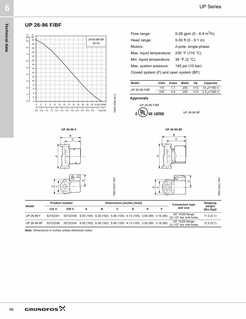
Te
ch
nic
al d
ata
UP Series6
66
UP 26-96 F/BF
Approvals
Note: Dimensions in inches unless otherwise noted.
TM
03
55
56
44
12
0 2 4 6 8 10 12 14 16 18 20 22 24 Q [US GPM]
0
2
4
6
8
10
12
14
16
18
20
22
24
26
28
30[ft]H
0.0 0.5 1.0 1.5 2.0 2.5 3.0 3.5 4.0 4.5 5.0 5.5 Q [m³/h]
0
1
2
3
4
5
6
7
8
9
[m]H
UP26-96F/BF
60 Hz
Flow range: 0-28 gpm (0 - 6.4 m3/h)
Head range: 0-30 ft (0 - 9.1 m)
Motors: 2-pole, single-phase
Max. liquid temperature: 230 °F (110 °C)
Min. liquid temperature: 36 °F (2 °C)
Max. system pressure: 145 psi (10 bar)
Closed system (F) and open system (BF)
Model Volts Amps Watts Hp Capacitor
UP 26-96 F/BF115 1.7 205 1/12 10 F/180 V
230 0.8 205 1/12 2.5 F/380 V
UP 26-96 F/BF
UP 26-96 BF
UP 26-96 F UP 26-96 BF
TM
03
85
33
19
07
TM
03
85
43
19
07
ModelProduct number Dimensions [inches (mm)]
Connection type and size
Shipping weight
[lbs (kg)]115 V 230 V A B C D E F
UP 26-96 F 52722341 52722338 6.50 (165) 6.38 (162) 5.06 (129) 4.13 (105) 3.50 (89) 3.16 (80)GF 15/26 flange
(2) 1/2" dia. bolt holes11.3 (5.1)
UP 26-96 BF 52722336 52722334 6.50 (165) 6.38 (162) 5.06 (129) 4.13 (105) 3.50 (89) 3.16 (80)GF 15/26 flange
(2) 1/2" dia. bolt holes12.5 (5.7)
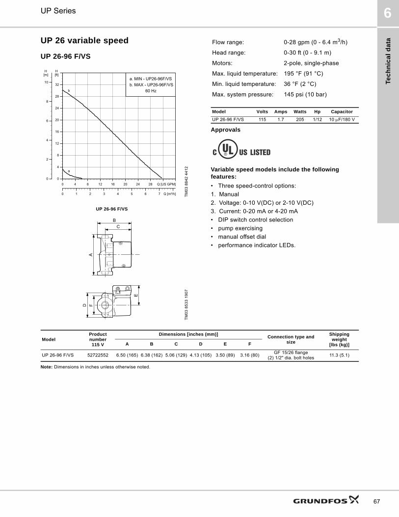
Tec
hn
ica
l d
ata
UP Series 6
67
UP 26 variable speed
UP 26-96 F/VS
Approvals
Variable speed models include the following features:
• Three speed-control options:
1. Manual
2. Voltage: 0-10 V(DC) or 2-10 V(DC)
3. Current: 0-20 mA or 4-20 mA
• DIP switch control selection
• pump exercising
• manual offset dial
• performance indicator LEDs.
Note: Dimensions in inches unless otherwise noted.
TM
03
88
42
44
12
UP 26-96 F/VS
TM
03
85
33
19
07
0 4 8 12 16 20 24 28 Q [US GPM]
0
4
8
12
16
20
24
28
32
[ft]H
0 1 2 3 4 5 6 7 Q [m³/h]
0
2
4
6
8
10
[m]H
a. MIN - UP26-96F/VS
b. MAX - UP26-96F/VS
60 Hzb
a
Flow range: 0-28 gpm (0 - 6.4 m3/h)
Head range: 0-30 ft (0 - 9.1 m)
Motors: 2-pole, single-phase
Max. liquid temperature: 195 °F (91 °C)
Min. liquid temperature: 36 °F (2 °C)
Max. system pressure: 145 psi (10 bar)
Model Volts Amps Watts Hp Capacitor
UP 26-96 F/VS 115 1.7 205 1/12 10 F/180 V
ModelProduct number115 V
Dimensions [inches (mm)]Connection type and
size
Shipping weight
[lbs (kg)]A B C D E F
UP 26-96 F/VS 52722552 6.50 (165) 6.38 (162) 5.06 (129) 4.13 (105) 3.50 (89) 3.16 (80)GF 15/26 flange
(2) 1/2" dia. bolt holes11.3 (5.1)
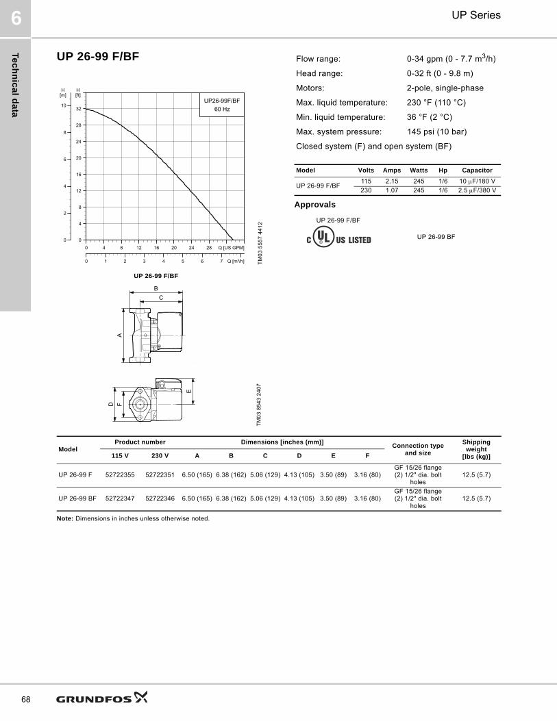
Te
ch
nic
al d
ata
UP Series6
68
UP 26-99 F/BF
Approvals
Note: Dimensions in inches unless otherwise noted.
TM
03
55
57
44
12
0 4 8 12 16 20 24 28 Q [US GPM]
0
4
8
12
16
20
24
28
32
[ft]H
0 1 2 3 4 5 6 7 Q [m³/h]
0
2
4
6
8
10
[m]H
UP26-99F/BF
60 Hz
Flow range: 0-34 gpm (0 - 7.7 m3/h)
Head range: 0-32 ft (0 - 9.8 m)
Motors: 2-pole, single-phase
Max. liquid temperature: 230 °F (110 °C)
Min. liquid temperature: 36 °F (2 °C)
Max. system pressure: 145 psi (10 bar)
Closed system (F) and open system (BF)
Model Volts Amps Watts Hp Capacitor
UP 26-99 F/BF115 2.15 245 1/6 10 F/180 V
230 1.07 245 1/6 2.5 F/380 V
UP 26-99 F/BF
UP 26-99 BF
UP 26-99 F/BF
TM
03
85
43
24
07
ModelProduct number Dimensions [inches (mm)]
Connection type and size
Shipping weight
[lbs (kg)]115 V 230 V A B C D E F
UP 26-99 F 52722355 52722351 6.50 (165) 6.38 (162) 5.06 (129) 4.13 (105) 3.50 (89) 3.16 (80)GF 15/26 flange(2) 1/2" dia. bolt
holes12.5 (5.7)
UP 26-99 BF 52722347 52722346 6.50 (165) 6.38 (162) 5.06 (129) 4.13 (105) 3.50 (89) 3.16 (80)GF 15/26 flange(2) 1/2" dia. bolt
holes12.5 (5.7)
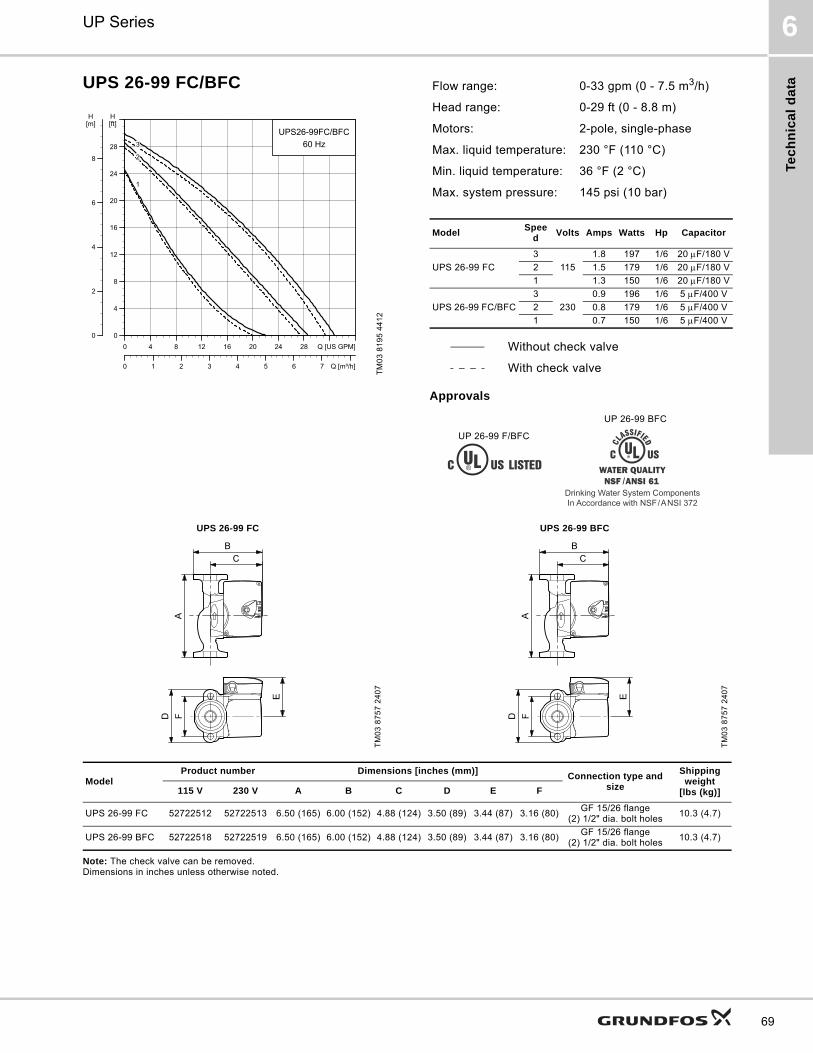
Tec
hn
ica
l d
ata
UP Series 6
69
UPS 26-99 FC/BFC
Approvals
Note: The check valve can be removed. Dimensions in inches unless otherwise noted.
TM
03
81
95
44
12
0 4 8 12 16 20 24 28 Q [US GPM]
0
4
8
12
16
20
24
28
[ft]H
0 1 2 3 4 5 6 7 Q [m³/h]
0
2
4
6
8
[m]H
UPS26-99FC/BFC
60 Hz
1
2
3
Flow range: 0-33 gpm (0 - 7.5 m3/h)
Head range: 0-29 ft (0 - 8.8 m)
Motors: 2-pole, single-phase
Max. liquid temperature: 230 °F (110 °C)
Min. liquid temperature: 36 °F (2 °C)
Max. system pressure: 145 psi (10 bar)
ModelSpee
dVolts Amps Watts Hp Capacitor
UPS 26-99 FC
3
115
1.8 197 1/6 20 F/180 V
2 1.5 179 1/6 20 F/180 V
1 1.3 150 1/6 20 F/180 V
UPS 26-99 FC/BFC
3
230
0.9 196 1/6 5 F/400 V
2 0.8 179 1/6 5 F/400 V
1 0.7 150 1/6 5 F/400 V
Without check valve
With check valve
UP 26-99 F/BFC
UP 26-99 BFC
Drinking Water System ComponentsIn Accordance with NSF/ANSI 372
UPS 26-99 FC UPS 26-99 BFC
TM
03
87
57
24
07
TM
03
87
57
24
07
ModelProduct number Dimensions [inches (mm)]
Connection type and size
Shipping weight
[lbs (kg)]115 V 230 V A B C D E F
UPS 26-99 FC 52722512 52722513 6.50 (165) 6.00 (152) 4.88 (124) 3.50 (89) 3.44 (87) 3.16 (80)GF 15/26 flange
(2) 1/2" dia. bolt holes10.3 (4.7)
UPS 26-99 BFC 52722518 52722519 6.50 (165) 6.00 (152) 4.88 (124) 3.50 (89) 3.44 (87) 3.16 (80)GF 15/26 flange
(2) 1/2" dia. bolt holes10.3 (4.7)
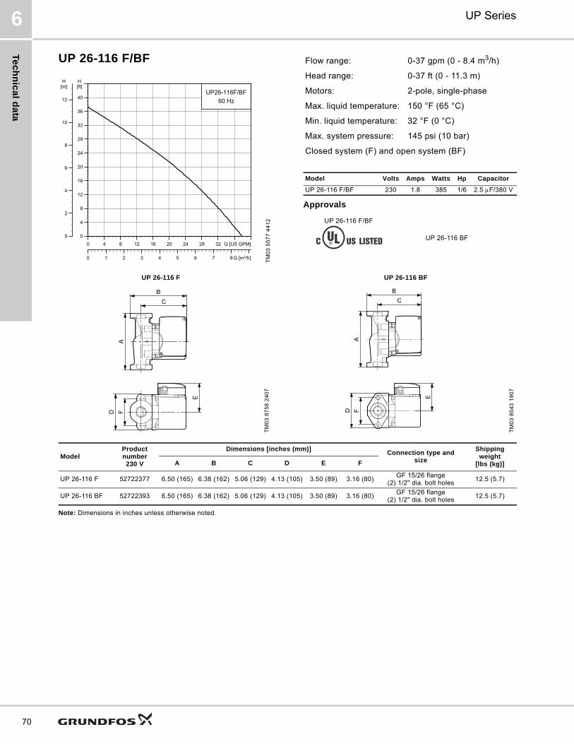
Te
ch
nic
al d
ata
UP Series6
70
UP 26-116 F/BF
Approvals
Note: Dimensions in inches unless otherwise noted.
TM
03
55
77
44
12
0 4 8 12 16 20 24 28 32 Q [US GPM]
0
4
8
12
16
20
24
28
32
36
40
[ft]H
0 1 2 3 4 5 6 7 8 Q [m³/h]
0
2
4
6
8
10
12
[m]H
UP26-116F/BF
60 Hz
Flow range: 0-37 gpm (0 - 8.4 m3/h)
Head range: 0-37 ft (0 - 11.3 m)
Motors: 2-pole, single-phase
Max. liquid temperature: 150 °F (65 °C)
Min. liquid temperature: 32 °F (0 °C)
Max. system pressure: 145 psi (10 bar)
Closed system (F) and open system (BF)
Model Volts Amps Watts Hp Capacitor
UP 26-116 F/BF 230 1.8 385 1/6 2.5 F/380 V
UP 26-116 F/BF
UP 26-116 BF
UP 26-116 F UP 26-116 BF
TM
03
87
58
24
07
TM
03
85
43
19
07
ModelProduct number230 V
Dimensions [inches (mm)]Connection type and
size
Shipping weight
[lbs (kg)]A B C D E F
UP 26-116 F 52722377 6.50 (165) 6.38 (162) 5.06 (129) 4.13 (105) 3.50 (89) 3.16 (80)GF 15/26 flange
(2) 1/2" dia. bolt holes12.5 (5.7)
UP 26-116 BF 52722393 6.50 (165) 6.38 (162) 5.06 (129) 4.13 (105) 3.50 (89) 3.16 (80)GF 15/26 flange
(2) 1/2" dia. bolt holes12.5 (5.7)

Tec
hn
ica
l d
ata
UP Series 6
71
UP 26-120 U
Approvals
Note: Dimensions in inches unless otherwise noted.
TM
03
55
46
44
12
UP 26-120 U
TM
03
87
61
24
07
0 2 4 6 8 10 12 14 16 Q [US GPM]
0
4
8
12
16
20
24
28
32
36
40
[ft]H
0.0 0.5 1.0 1.5 2.0 2.5 3.0 3.5 Q [m³/h]
0
2
4
6
8
10
12
[m]H
UP26-120U
60 Hz
Flow range: 0-19 gpm (0 - 4.3 m3/h)
Head range: 0-38 ft (0 - 11.6 m)
Motors: 2-pole, single-phase
Max. liquid temperature: 203 °F (95 °C)
Min. liquid temperature: 32 °F (0 °C)
Max. system pressure: 145 psi (10 bar)
Closed system
Model Volts Amps Watts Hp Capacitor
UP 26-120 U115 2.15 215 1/6 10 F/180 V
230 1.07 220 1/6 2.5 F/380 V
ModelProduct number Dimensions [inches (mm)]
Connection type and sizeShipping
weight[lbs (kg)]115 V 230 V A B C D E
UP 26-120 U 52722435 52722436 7.06 (179) 5.88 (149) 5.06 (129) 4.88 (124) 3.50 (89) GF 125 union - 1 1/4" NPSM 10.5 (4.8)
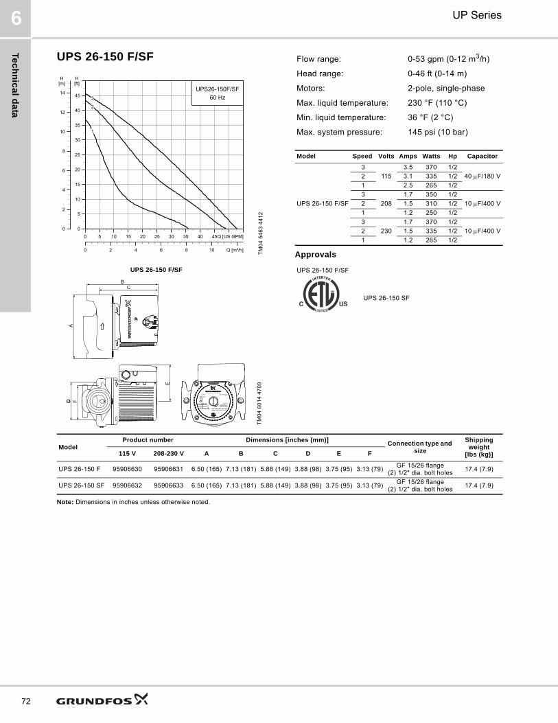
Te
ch
nic
al d
ata
UP Series6
72
UPS 26-150 F/SF
Approvals
Note: Dimensions in inches unless otherwise noted.
TM
04
54
63
44
12
UPS 26-150 F/SF
TM
04
60
14
47
09
0 5 10 15 20 25 30 35 40 45Q [US GPM]
0
5
10
15
20
25
30
35
40
45
[ft]H
0 2 4 6 8 10 Q [m³/h]
0
2
4
6
8
10
12
14
[m]H
UPS26-150F/SF
60 Hz
1
2
3
A
BC
D FD
E
Flow range: 0-53 gpm (0-12 m3/h)
Head range: 0-46 ft (0-14 m)
Motors: 2-pole, single-phase
Max. liquid temperature: 230 °F (110 °C)
Min. liquid temperature: 36 °F (2 °C)
Max. system pressure: 145 psi (10 bar)
Model Speed Volts Amps Watts Hp Capacitor
UPS 26-150 F/SF
3
115
3.5 370 1/2
40 F/180 V2 3.1 335 1/2
1 2.5 265 1/2
3
208
1.7 350 1/2
10 F/400 V2 1.5 310 1/2
1 1.2 250 1/2
3
230
1.7 370 1/2
10 F/400 V2 1.5 335 1/2
1 1.2 265 1/2
UPS 26-150 F/SF
UPS 26-150 SF
ModelProduct number Dimensions [inches (mm)]
Connection type and size
Shipping weight
[lbs (kg)]115 V 208-230 V A B C D E F
UPS 26-150 F 95906630 95906631 6.50 (165) 7.13 (181) 5.88 (149) 3.88 (98) 3.75 (95) 3.13 (79)GF 15/26 flange
(2) 1/2" dia. bolt holes17.4 (7.9)
UPS 26-150 SF 95906632 95906633 6.50 (165) 7.13 (181) 5.88 (149) 3.88 (98) 3.75 (95) 3.13 (79)GF 15/26 flange
(2) 1/2" dia. bolt holes17.4 (7.9)

Tec
hn
ica
l d
ata
UP Series 6
73
UP 43-44 F/BF
Approvals
Note: Dimensions in inches unless otherwise noted.
TM
03
55
58
44
12
UP 43-44 F/BF
TM
03
85
44
19
07
0 5 10 15 20 25 30 35 40 45 50 Q [US GPM]
0
1
2
3
4
5
6
7
8
9
10
11
12
13
14
[ft]H
0 2 4 6 8 10 12 Q [m³/h]
0.0
0.5
1.0
1.5
2.0
2.5
3.0
3.5
4.0
[m]H
UP43-44F/BF
60 Hz
Flow range: 0-68 gpm (0 - 15.4 m3/h)
Head range: 0 - 13.5 ft (0 - 4.1 m)
Motors: 2-pole, single-phase
Max. liquid temperature: 230 °F (110 °C)
Min. liquid temperature: 32 °F (0 °C)
Max. system pressure: 145 psi (10 bar)
Closed system (F) and open system (BF)
Model Volts Amps Watts Hp Capacitor
UP 43-44 F/BF115 2.15 215 1/6 10 F/180 V
230 1.07 220 1/6 2.5 F/380 V
UP 43-44 F/BF UP 43-44 BF
File 6591
ModelProduct number Dimensions [inches (mm)]
Connection type and size
Shipping weight
[lbs (kg)]115 V 230 V A B C D E F
UP 43-44 F 52722437 52722438 8.50 (216) 6.69 (170) 5.19 (132) 4.75 (121) 3.50 (89) 3.44 (87)GF 40/43 flange
(2) 1/2" dia. bolt holes13.5 (6.1)
UP 43-44 BF 52722439 52722440 8.50 (216) 6.69 (170) 5.19 (132) 4.75 (121) 3.50 (89) 3.44 (87)GF 40/43 flange
(2) 1/2" dia. bolt holes15 (6.8)
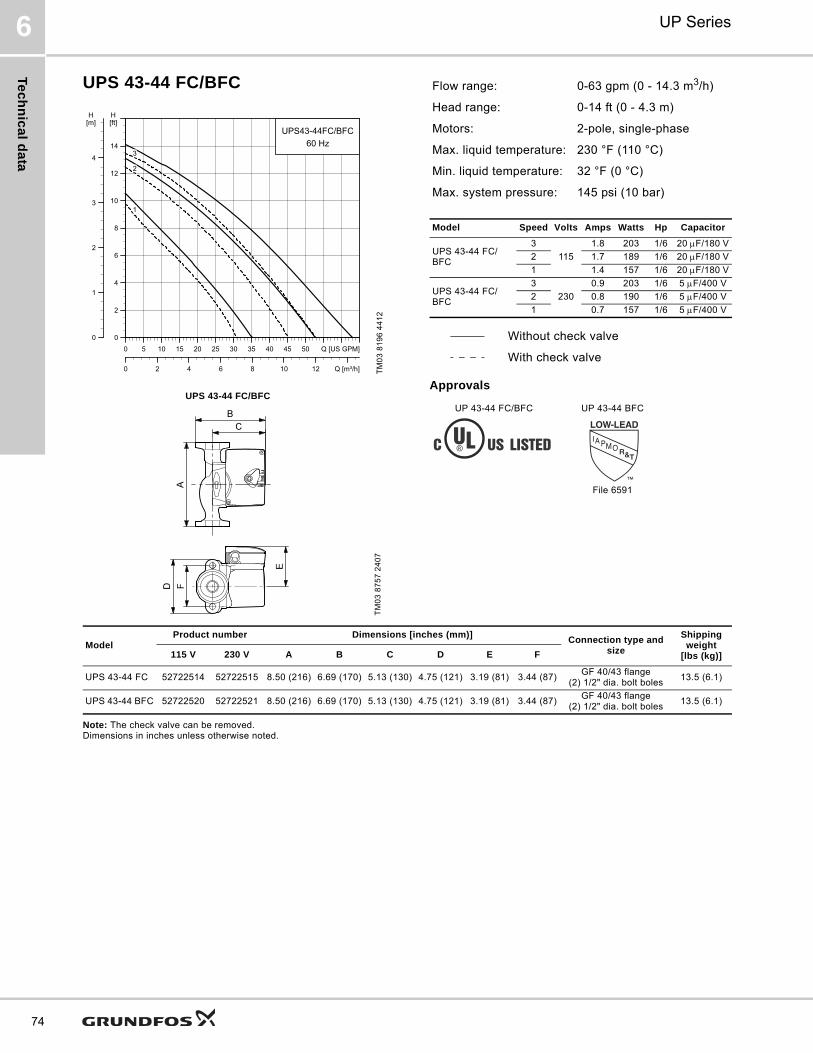
Te
ch
nic
al d
ata
UP Series6
74
UPS 43-44 FC/BFC
Approvals
Note: The check valve can be removed. Dimensions in inches unless otherwise noted.
TM
03
81
96
44
12
UPS 43-44 FC/BFC
TM
03
87
57
24
07
0 5 10 15 20 25 30 35 40 45 50 Q [US GPM]0
2
4
6
8
10
12
14
[ft]H
0 2 4 6 8 10 12 Q [m³/h]
0
1
2
3
4
[m]H
UPS43-44FC/BFC60 Hz
1
2
3
Flow range: 0-63 gpm (0 - 14.3 m3/h)
Head range: 0-14 ft (0 - 4.3 m)
Motors: 2-pole, single-phase
Max. liquid temperature: 230 °F (110 °C)
Min. liquid temperature: 32 °F (0 °C)
Max. system pressure: 145 psi (10 bar)
Model Speed Volts Amps Watts Hp Capacitor
UPS 43-44 FC/BFC
3
115
1.8 203 1/6 20 F/180 V
2 1.7 189 1/6 20 F/180 V
1 1.4 157 1/6 20 F/180 V
UPS 43-44 FC/BFC
3
230
0.9 203 1/6 5 F/400 V
2 0.8 190 1/6 5 F/400 V
1 0.7 157 1/6 5 F/400 V
Without check valve
With check valve
UP 43-44 FC/BFC UP 43-44 BFC
File 6591
ModelProduct number Dimensions [inches (mm)]
Connection type and size
Shipping weight
[lbs (kg)]115 V 230 V A B C D E F
UPS 43-44 FC 52722514 52722515 8.50 (216) 6.69 (170) 5.13 (130) 4.75 (121) 3.19 (81) 3.44 (87)GF 40/43 flange
(2) 1/2" dia. bolt boles13.5 (6.1)
UPS 43-44 BFC 52722520 52722521 8.50 (216) 6.69 (170) 5.13 (130) 4.75 (121) 3.19 (81) 3.44 (87)GF 40/43 flange
(2) 1/2" dia. bolt boles13.5 (6.1)
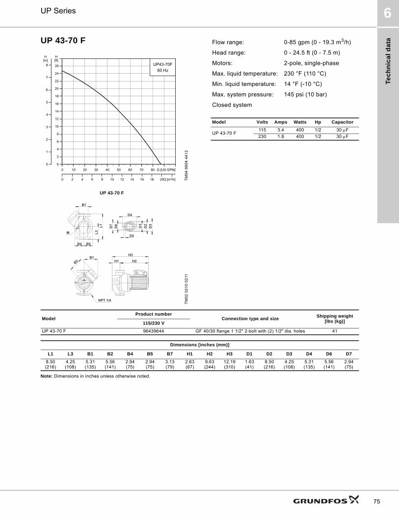
Tec
hn
ica
l d
ata
UP Series 6
75
UP 43-70 F
Note: Dimensions in inches unless otherwise noted.
TM
04
99
04
44
12
UP 43-70 F
TM
02
02
10
02
11
0 10 20 30 40 50 60 70 80 Q [US GPM]0
2
4
6
8
10
12
14
16
18
20
22
24
26
[ft]H
0 2 4 6 8 10 12 14 16 18 20Q [m³/h]
0
1
2
3
4
5
6
7
8[m]H
UP43-70F60 Hz
D6 D2
D3
D7 D1
D4
D5
H1 H2
H3
NPT 1/4
B1B2
B7
L1
B4 B5
L3M
Flow range: 0-85 gpm (0 - 19.3 m3/h)
Head range: 0 - 24.5 ft (0 - 7.5 m)
Motors: 2-pole, single-phase
Max. liquid temperature: 230 °F (110 °C)
Min. liquid temperature: 14 °F (-10 °C)
Max. system pressure: 145 psi (10 bar)
Closed system
Model Volts Amps Watts Hp Capacitor
UP 43-70 F115 3.4 400 1/2 30 F
230 1.8 400 1/2 30 F
ModelProduct number
Connection type and sizeShipping weight
[lbs (kg)]115/230 V
UP 43-70 F 96439644 GF 40/30 flange 1 1/2" 2-bolt with (2) 1/2" dia. holes 41
Dimensions [inches (mm)]
L1 L3 B1 B2 B4 B5 B7 H1 H2 H3 D1 D2 D3 D4 D6 D7
8.50 (216)
4.25 (108)
5.31 (135)
5.56 (141)
2.94 (75)
2.94 (75)
3.13 (79)
2.63 (67)
9.63 (244)
12.19 (310)
1.63 (41)
8.50 (216)
4.25 (108)
5.31 (135)
5.56 (141)
2.94 (75)
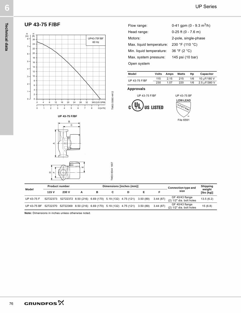
Te
ch
nic
al d
ata
UP Series6
76
UP 43-75 F/BF
Approvals
Note: Dimensions in inches unless otherwise noted.
TM
03
55
60
44
12
UP 43-75 F/BF
TM
03
85
44
19
07
0 4 8 12 16 20 24 28 32 36Q [US GPM]
0
2
4
6
8
10
12
14
16
18
20
22
24
26
[ft]H
0 1 2 3 4 5 6 7 8 Q [m³/h]
0
1
2
3
4
5
6
7
8[m]H
UP43-75F/BF
60 Hz
Flow range: 0-41 gpm (0 - 9.3 m3/h)
Head range: 0-25 ft (0 - 7.6 m)
Motors: 2-pole, single-phase
Max. liquid temperature: 230 °F (110 °C)
Min. liquid temperature: 36 °F (2 °C)
Max. system pressure: 145 psi (10 bar)
Open system
Model Volts Amps Watts Hp Capacitor
UP 43-75 F/BF115 2.15 215 1/6 10 F/180 V
230 1.07 220 1/6 2.5 F/380 V
UP 43-75 F/BF UP 43-75 BF
File 6591
ModelProduct number Dimensions [inches (mm)]
Connection type and size
Shipping weight
[lbs (kg)]115 V 230 V A B C D E F
UP 43-75 F 52722373 52722372 8.50 (216) 6.69 (170) 5.19 (132) 4.75 (121) 3.50 (89) 3.44 (87)GF 40/43 flange
(2) 1/2" dia. bolt holes13.5 (6.2)
UP 43-75 BF 52722370 52722369 8.50 (216) 6.69 (170) 5.19 (132) 4.75 (121) 3.50 (89) 3.44 (87)GF 40/43 flange
(2) 1/2" dia. bolt holes15 (6.8)
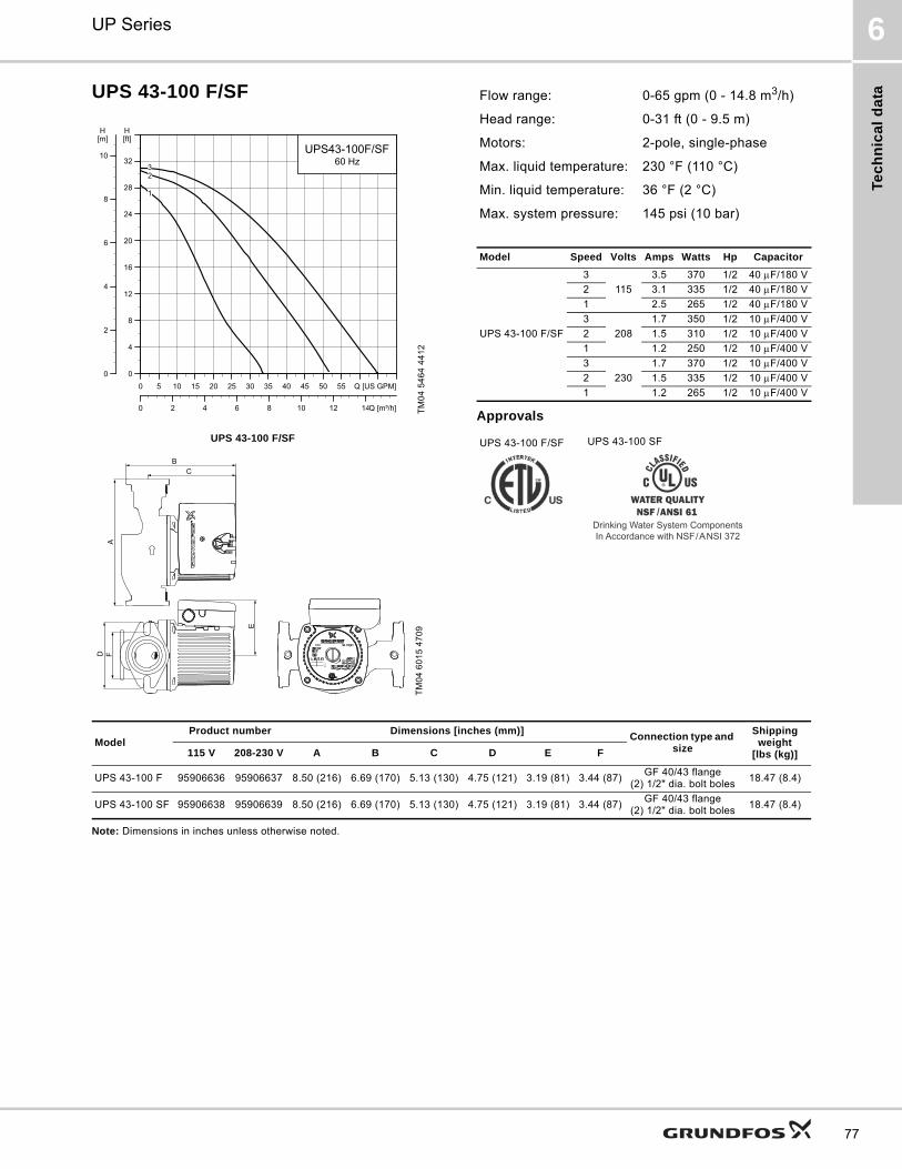
Tec
hn
ica
l d
ata
UP Series 6
77
UPS 43-100 F/SF
Approvals
Note: Dimensions in inches unless otherwise noted.
TM
04
54
64
44
12
UPS 43-100 F/SF
TM
04
60
15
47
09
0 5 10 15 20 25 30 35 40 45 50 55 Q [US GPM]0
4
8
12
16
20
24
28
32
[ft]H
0 2 4 6 8 10 12 14Q [m³/h]
0
2
4
6
8
10
[m]H
UPS43-100F/SF60 Hz
1
23
BC
AD F
E
Flow range: 0-65 gpm (0 - 14.8 m3/h)
Head range: 0-31 ft (0 - 9.5 m)
Motors: 2-pole, single-phase
Max. liquid temperature: 230 °F (110 °C)
Min. liquid temperature: 36 °F (2 °C)
Max. system pressure: 145 psi (10 bar)
Model Speed Volts Amps Watts Hp Capacitor
UPS 43-100 F/SF
3
115
3.5 370 1/2 40 F/180 V
2 3.1 335 1/2 40 F/180 V
1 2.5 265 1/2 40 F/180 V
3
208
1.7 350 1/2 10 F/400 V
2 1.5 310 1/2 10 F/400 V
1 1.2 250 1/2 10 F/400 V
3
230
1.7 370 1/2 10 F/400 V
2 1.5 335 1/2 10 F/400 V
1 1.2 265 1/2 10 F/400 V
UPS 43-100 F/SF UPS 43-100 SF
Drinking Water System ComponentsIn Accordance with NSF/ANSI 372
ModelProduct number Dimensions [inches (mm)]
Connection type and size
Shipping weight
[lbs (kg)]115 V 208-230 V A B C D E F
UPS 43-100 F 95906636 95906637 8.50 (216) 6.69 (170) 5.13 (130) 4.75 (121) 3.19 (81) 3.44 (87)GF 40/43 flange
(2) 1/2" dia. bolt boles18.47 (8.4)
UPS 43-100 SF 95906638 95906639 8.50 (216) 6.69 (170) 5.13 (130) 4.75 (121) 3.19 (81) 3.44 (87)GF 40/43 flange
(2) 1/2" dia. bolt boles18.47 (8.4)

Te
ch
nic
al d
ata
UP Series6
78
UP 43-110 F
Approvals
Note: Dimensions in inches unless otherwise noted.
TM
05
60
21
44
12
0 10 20 30 40 50 60 70 80 90Q [US GPM]0
4
8
12
16
20
24
28
32
36
[ft]H
0 5 10 15 20 Q [m³/h]
0
2
4
6
8
10
[m]H
UP43-110F60 Hz
Flow range: 0-98 gpm (0 - 22.3 m3/h)
Head range: 0-37 ft (0 - 11.3 m)
Motors: 2-pole, single-phase
Max. liquid temperature: 230 °F (110 °C)
Min. liquid temperature: 14 °F (-10 °C)
Max. system pressure: 145 psi (10 bar)
Closed system
Model Volts Amps Watts Hp Capacitor
UP 43-110 F115 5.1 590 3/4 60 F
230 2.7 590 3/4 60 F
UP 43-110 F
TM
02
01
20
02
11
D6 D2
D3
D7 D1
D4
D5
H1 H2
H3
NPT 1/4
B1B2
B7
L1
B4 B5
L3M
ModelProduct number
Connection type and sizeShipping weight
[lbs (kg)]115 V/230 V
UP 43-110 F 96439643GF 40/43 flange
1 1/2"41.2 (18.7)
Dimensions [inches (mm)]
L1 L3 B1 B2 B4 B5 B7 H1 H2 H3 D1 D2 D3 D4 D6 D7 M
8.50 (216)
4.25 (108)
5.25 (133)
5.56 (141)
2.94 (75)
2.94 (75)
3.13 (79)
2.63 (67)
9.63 (244)
12.19 (310)
1.63 (41)
2.94 (75)
3.44 (87)
4.75 (121)
2.06 (52)
2.50 (64)
0.47 (12)
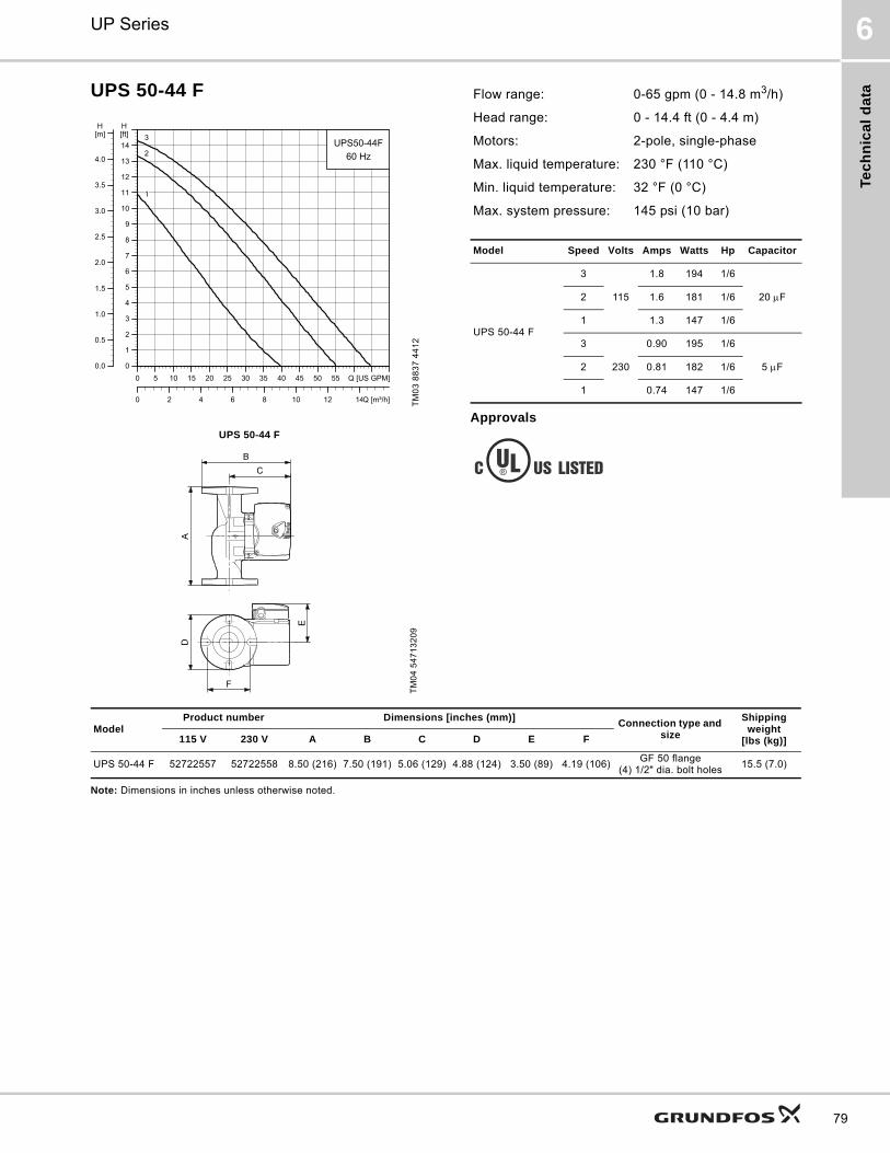
Tec
hn
ica
l d
ata
UP Series 6
79
UPS 50-44 F
Approvals
Note: Dimensions in inches unless otherwise noted.
TM
03
88
37
44
12
UPS 50-44 F
TM
04
54
71
32
09
0 5 10 15 20 25 30 35 40 45 50 55 Q [US GPM]
0
1
2
3
4
5
6
7
8
9
10
11
12
13
14
[ft]H
0 2 4 6 8 10 12 14Q [m³/h]
0.0
0.5
1.0
1.5
2.0
2.5
3.0
3.5
4.0
[m]H
UPS50-44F
60 Hz
1
2
3
Flow range: 0-65 gpm (0 - 14.8 m3/h)
Head range: 0 - 14.4 ft (0 - 4.4 m)
Motors: 2-pole, single-phase
Max. liquid temperature: 230 °F (110 °C)
Min. liquid temperature: 32 °F (0 °C)
Max. system pressure: 145 psi (10 bar)
Model Speed Volts Amps Watts Hp Capacitor
UPS 50-44 F
3
115
1.8 194 1/6
20 F2 1.6 181 1/6
1 1.3 147 1/6
3
230
0.90 195 1/6
5 F2 0.81 182 1/6
1 0.74 147 1/6
ModelProduct number Dimensions [inches (mm)]
Connection type and size
Shipping weight
[lbs (kg)]115 V 230 V A B C D E F
UPS 50-44 F 52722557 52722558 8.50 (216) 7.50 (191) 5.06 (129) 4.88 (124) 3.50 (89) 4.19 (106)GF 50 flange
(4) 1/2" dia. bolt holes15.5 (7.0)
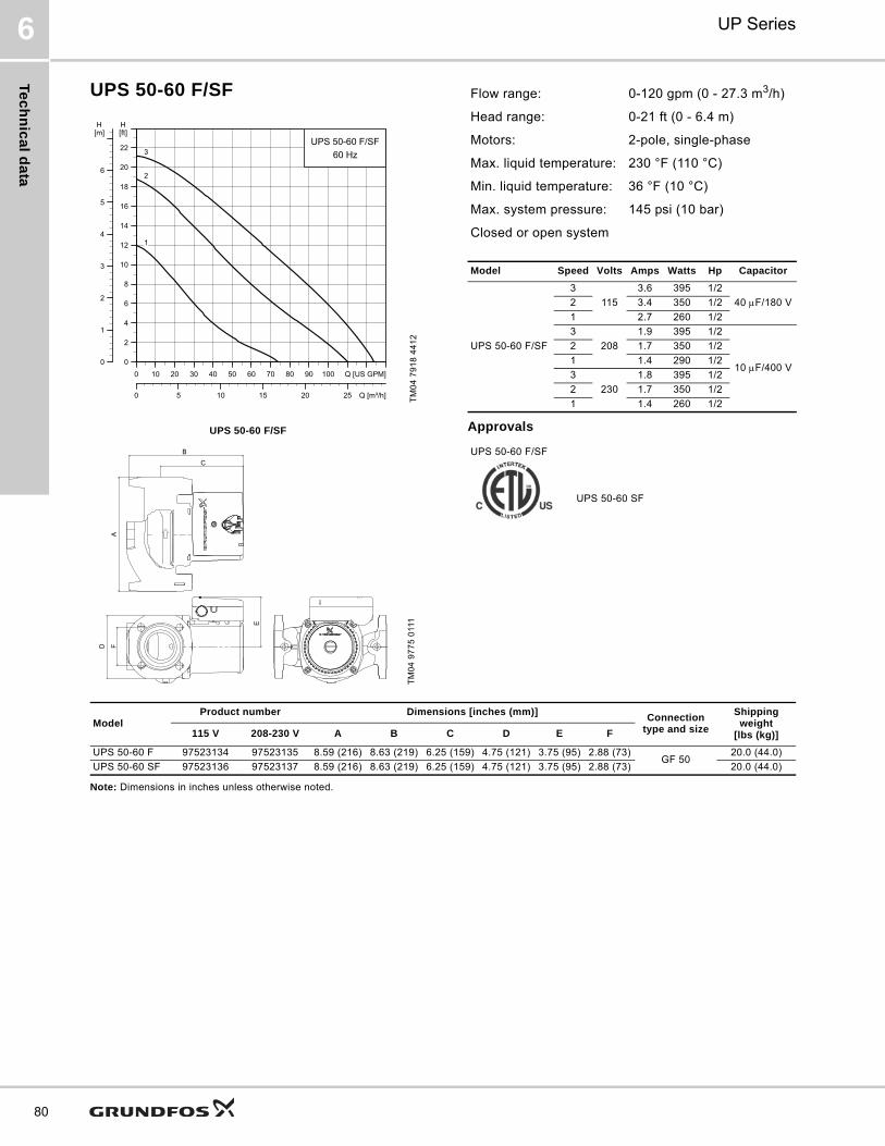
Te
ch
nic
al d
ata
UP Series6
80
UPS 50-60 F/SF
Approvals
Note: Dimensions in inches unless otherwise noted.
TM
04
79
18
44
12
UPS 50-60 F/SF
TM
04
97
75
011
1
0 10 20 30 40 50 60 70 80 90 100 Q [US GPM]0
2
4
6
8
10
12
14
16
18
20
22
[ft]H
0 5 10 15 20 25 Q [m³/h]
0
1
2
3
4
5
6
[m]H
UPS 50-60 F/SF60 Hz3
2
1
B
C
A
D F
E
Flow range: 0-120 gpm (0 - 27.3 m3/h)
Head range: 0-21 ft (0 - 6.4 m)
Motors: 2-pole, single-phase
Max. liquid temperature: 230 °F (110 °C)
Min. liquid temperature: 36 °F (10 °C)
Max. system pressure: 145 psi (10 bar)
Closed or open system
Model Speed Volts Amps Watts Hp Capacitor
UPS 50-60 F/SF
3
115
3.6 395 1/2
40 F/180 V2 3.4 350 1/2
1 2.7 260 1/2
3
208
1.9 395 1/2
10 F/400 V
2 1.7 350 1/2
1 1.4 290 1/2
3
230
1.8 395 1/2
2 1.7 350 1/2
1 1.4 260 1/2
UPS 50-60 F/SF
UPS 50-60 SF
ModelProduct number Dimensions [inches (mm)]
Connection type and size
Shipping weight
[lbs (kg)]115 V 208-230 V A B C D E F
UPS 50-60 F 97523134 97523135 8.59 (216) 8.63 (219) 6.25 (159) 4.75 (121) 3.75 (95) 2.88 (73)GF 50
20.0 (44.0)
UPS 50-60 SF 97523136 97523137 8.59 (216) 8.63 (219) 6.25 (159) 4.75 (121) 3.75 (95) 2.88 (73) 20.0 (44.0)

Tec
hn
ica
l d
ata
UP Series 6
81
UP 50-75 F
Approvals
Note: Dimensions in inches unless otherwise noted.
TM
03
55
45
44
12
0 4 8 12 16 20 24 28 32 36Q [US GPM]0
2
4
6
8
10
12
14
16
18
20
22
24
26
[ft]H
0 2 4 6 8 Q [m³/h]
0
1
2
3
4
5
6
7
8[m]H
UP50-75F60 Hz
Flow range: 0-41 gpm (0 - 9.3 m3/h)
Head range: 0-25 ft (0 - 7.6 m)
Motors: 2-pole, single-phase
Max. liquid temperature: 230 °F (110 °C)
Min. liquid temperature: 32 °F (0 °C)
Max. system pressure: 145 psi (10 bar)
Closed system
Model Volts Amps Watts Hp Capacitor
UP 50-75 F115 2.15 215 1/6 10 F/180 V
230 1.07 220 1/6 2.5 F/400 V
UP 50-75 F
TM
03
87
60
24
07
ModelProduct number Dimensions [inches (mm)] Connection type
and sizeShipping weight
[lbs (kg)]115 V 230 V A B C D E F
UP 50-75 F 52722352 52722353 8.50 (216) 7.50 (191) 5.06 (129) 4.88 (124) 3.50 (89) 4.19 (106)GF 50 flange
(4) 1/2" dia. bolt holes15.5 (7.0)
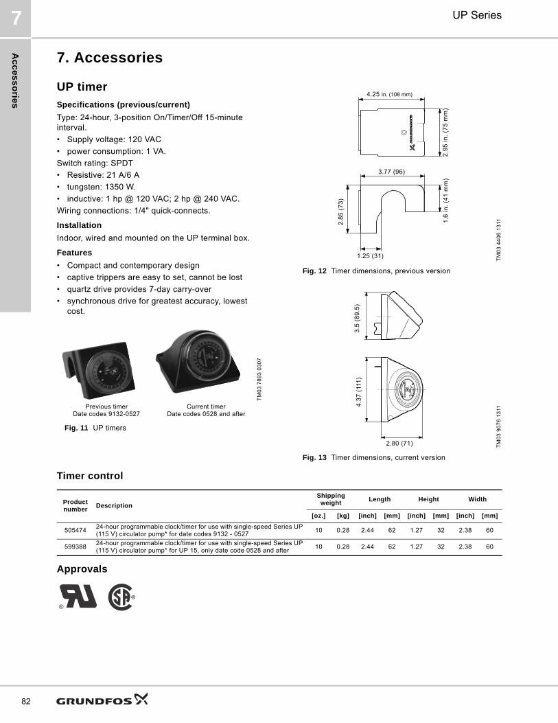
Ac
ce
ss
orie
s
UP Series7
82
7. Accessories
UP timer
Specifications (previous/current)
Type: 24-hour, 3-position On/Timer/Off 15-minute interval.
• Supply voltage: 120 VAC
• power consumption: 1 VA.
Switch rating: SPDT
• Resistive: 21 A/6 A
• tungsten: 1350 W.
• inductive: 1 hp @ 120 VAC; 2 hp @ 240 VAC.
Wiring connections: 1/4" quick-connects.
Installation
Indoor, wired and mounted on the UP terminal box.
Features
• Compact and contemporary design
• captive trippers are easy to set, cannot be lost
• quartz drive provides 7-day carry-over
• synchronous drive for greatest accuracy, lowest cost.
Fig. 11 UP timers
Fig. 12 Timer dimensions, previous version
Fig. 13 Timer dimensions, current version
Timer control
Approvals
TM
03
78
93
03
07
Previous timerDate codes 9132-0527
Current timerDate codes 0528 and after
TM
03
44
06
13
11T
M0
3 9
07
6 1
311
4.25 in. (108 mm)
2.8
5 (
73
)
1.25 (31)
1.6
in.
(41
mm
)2
.95
in.
(75
mm
)
3.77 (96)
3.5
(8
9.5
)4
.37
(11
1)
2.80 (71)
Product number
Description
Shipping weight
Length Height Width
[oz.] [kg] [inch] [mm] [inch] [mm] [inch] [mm]
50547424-hour programmable clock/timer for use with single-speed Series UP (115 V) circulator pump* for date codes 9132 - 0527
10 0.28 2.44 62 1.27 32 2.38 60
59938824-hour programmable clock/timer for use with single-speed Series UP (115 V) circulator pump* for UP 15, only date code 0528 and after
10 0.28 2.44 62 1.27 32 2.38 60
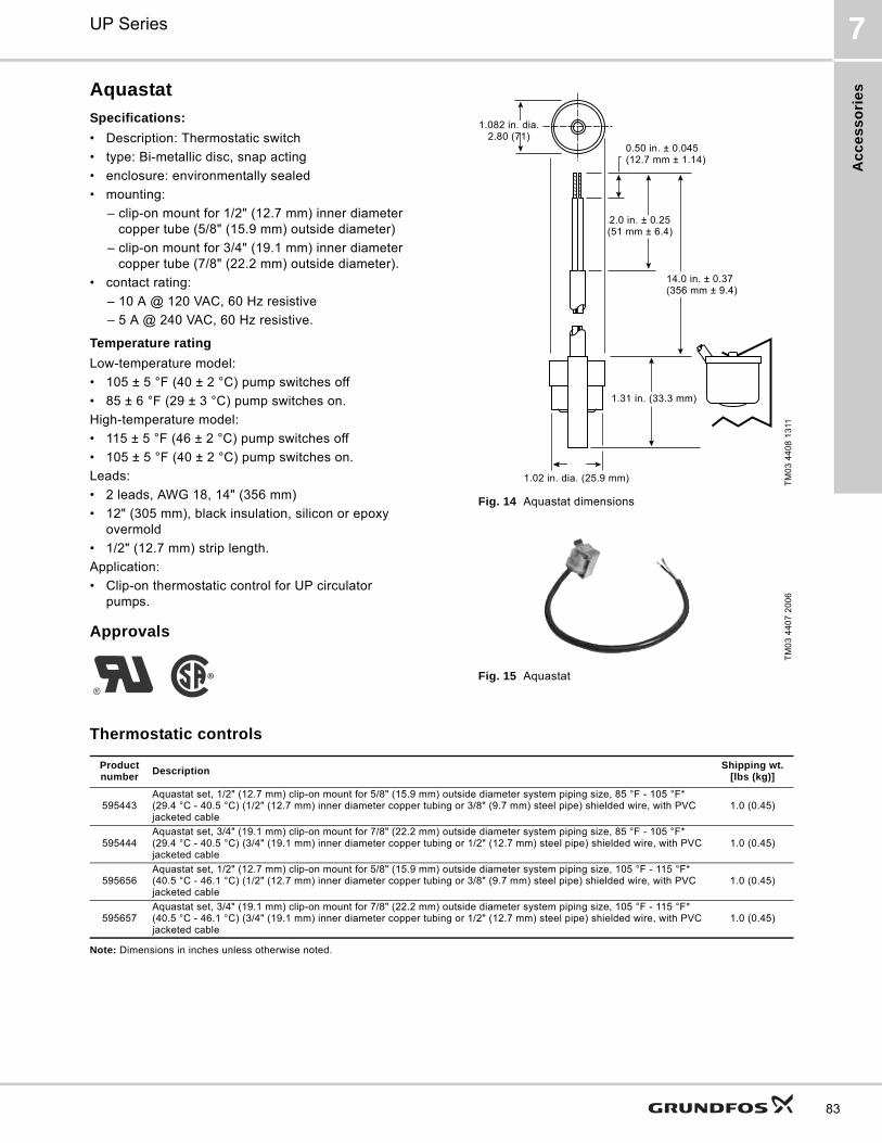
Ac
ce
ss
ori
es
UP Series 7
83
Aquastat
Specifications:
• Description: Thermostatic switch
• type: Bi-metallic disc, snap acting
• enclosure: environmentally sealed
• mounting:
– clip-on mount for 1/2" (12.7 mm) inner diameter copper tube (5/8" (15.9 mm) outside diameter)
– clip-on mount for 3/4" (19.1 mm) inner diameter copper tube (7/8" (22.2 mm) outside diameter).
• contact rating:
– 10 A @ 120 VAC, 60 Hz resistive
– 5 A @ 240 VAC, 60 Hz resistive.
Temperature rating
Low-temperature model:
• 105 ± 5 °F (40 ± 2 °C) pump switches off
• 85 ± 6 °F (29 ± 3 °C) pump switches on.
High-temperature model:
• 115 ± 5 °F (46 ± 2 °C) pump switches off
• 105 ± 5 °F (40 ± 2 °C) pump switches on.
Leads:
• 2 leads, AWG 18, 14" (356 mm)
• 12" (305 mm), black insulation, silicon or epoxy overmold
• 1/2" (12.7 mm) strip length.
Application:
• Clip-on thermostatic control for UP circulator pumps.
Approvals
Fig. 14 Aquastat dimensions
Fig. 15 Aquastat
Thermostatic controls
Note: Dimensions in inches unless otherwise noted.
TM
03
44
08
13
11T
M0
3 4
40
7 2
00
6
1.082 in. dia. 2.80 (71)
0.50 in. ± 0.045 (12.7 mm ± 1.14)
1.02 in. dia. (25.9 mm)
14.0 in. ± 0.37 (356 mm ± 9.4)
2.0 in. ± 0.25 (51 mm ± 6.4)
1.31 in. (33.3 mm)
Product number
DescriptionShipping wt.
[lbs (kg)]
595443Aquastat set, 1/2" (12.7 mm) clip-on mount for 5/8" (15.9 mm) outside diameter system piping size, 85 °F - 105 °F* (29.4 °C - 40.5 °C) (1/2" (12.7 mm) inner diameter copper tubing or 3/8" (9.7 mm) steel pipe) shielded wire, with PVC jacketed cable
1.0 (0.45)
595444Aquastat set, 3/4" (19.1 mm) clip-on mount for 7/8" (22.2 mm) outside diameter system piping size, 85 °F - 105 °F* (29.4 °C - 40.5 °C) (3/4" (19.1 mm) inner diameter copper tubing or 1/2" (12.7 mm) steel pipe) shielded wire, with PVC jacketed cable
1.0 (0.45)
595656Aquastat set, 1/2" (12.7 mm) clip-on mount for 5/8" (15.9 mm) outside diameter system piping size, 105 °F - 115 °F* (40.5 °C - 46.1 °C) (1/2" (12.7 mm) inner diameter copper tubing or 3/8" (9.7 mm) steel pipe) shielded wire, with PVC jacketed cable
1.0 (0.45)
595657Aquastat set, 3/4" (19.1 mm) clip-on mount for 7/8" (22.2 mm) outside diameter system piping size, 105 °F - 115 °F* (40.5 °C - 46.1 °C) (3/4" (19.1 mm) inner diameter copper tubing or 1/2" (12.7 mm) steel pipe) shielded wire, with PVC jacketed cable
1.0 (0.45)
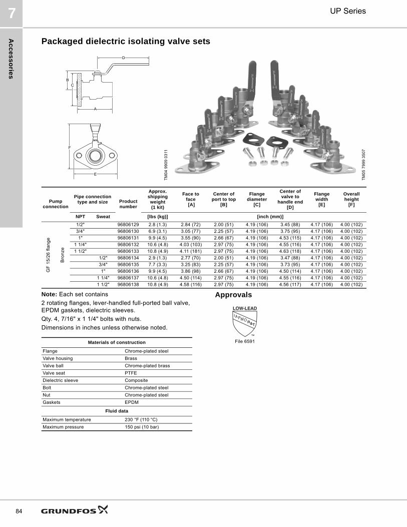
Ac
ce
ss
orie
s
UP Series7
84
Packaged dielectric isolating valve sets
Note: Each set contains
2 rotating flanges, lever-handled full-ported ball valve, EPDM gaskets, dielectric sleeves.
Qty. 4, 7/16" x 1 1/4" bolts with nuts.
Dimensions in inches unless otherwise noted.
Approvals
TM
04
99
09
03
11
TM
05
79
99
35
07
A
BC
D
E
F
Pump connection
Pipe connection type and size Product
number
Approx.shipping weight(1 kit)
Face toface [A]
Center ofport to top
[B]
Flangediameter
[C]
Center of valve to
handle end[D]
Flangewidth
[E]
Overallheight
[F]
NPT Sweat [lbs (kg)] [inch (mm)]
GF
15
/26
fla
ng
e
Bro
nze
1/2" 96806129 2.8 (1.3) 2.84 (72) 2.00 (51) 4.19 (106) 3.45 (88) 4.17 (106) 4.00 (102)
3/4" 96806130 6.9 (3.1) 3.05 (77) 2.25 (57) 4.19 (106) 3.75 (95) 4.17 (106) 4.00 (102)
1" 96806131 9.9 (4.5) 3.55 (90) 2.66 (67) 4.19 (106) 4.53 (115) 4.17 (106) 4.00 (102)
1 1/4" 96806132 10.6 (4.8) 4.03 (103) 2.97 (75) 4.19 (106) 4.55 (116) 4.17 (106) 4.00 (102)
1 1/2" 96806133 10.8 (4.9) 4.11 (181) 2.97 (75) 4.19 (106) 4.63 (118) 4.17 (106) 4.00 (102)
1/2" 96806134 2.9 (1.3) 2.77 (70) 2.00 (51) 4.19 (106) 3.47 (88) 4.17 (106) 4.00 (102)
3/4" 96806135 7.7 (3.3) 3.25 (83) 2.25 (57) 4.19 (106) 3.73 (95) 4.17 (106) 4.00 (102)
1" 96806136 9.9 (4.5) 3.86 (98) 2.66 (67) 4.19 (106) 4.50 (114) 4.17 (106) 4.00 (102)
1 1/4" 96806137 10.6 (4.8) 4.50 (114) 2.97 (75) 4.19 (106) 4.55 (116) 4.17 (106) 4.00 (102)
1 1/2" 96806138 10.8 (4.9) 4.58 (116) 2.97 (75) 4.19 (106) 4.56 (117) 4.17 (106) 4.00 (102)
Materials of construction
Flange Chrome-plated steel
Valve housing Brass
Valve ball Chrome-plated brass
Valve seat PTFE
Dielectric sleeve Composite
Bolt Chrome-plated steel
Nut Chrome-plated steel
Gaskets EPDM
Fluid data
Maximum temperature 230 °F (110 °C)
Maximum pressure 150 psi (10 bar)
File 6591
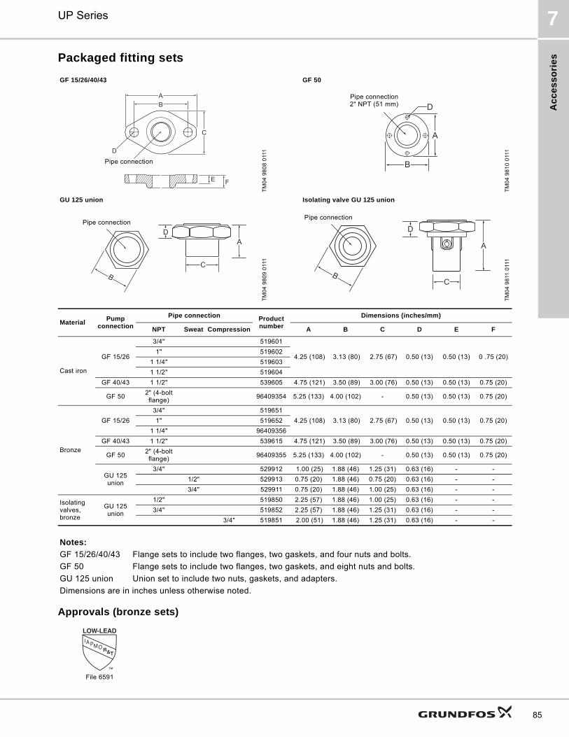
Ac
ce
ss
ori
es
UP Series 7
85
Packaged fitting sets
Approvals (bronze sets)
GF 15/26/40/43 GF 50
TM
04
98
08
011
1
TM
04
98
10
011
1
GU 125 union Isolating valve GU 125 union
TM
04
98
09
011
1
TM
04
98
11 0
111
MaterialPump
connection
Pipe connection Product number
Dimensions (inches/mm)
NPT Sweat Compression A B C D E F
Cast iron
GF 15/26
3/4" 519601
4.25 (108) 3.13 (80) 2.75 (67) 0.50 (13) 0.50 (13) 0 .75 (20)1" 519602
1 1/4" 519603
1 1/2" 519604
GF 40/43 1 1/2" 539605 4.75 (121) 3.50 (89) 3.00 (76) 0.50 (13) 0.50 (13) 0.75 (20)
GF 502" (4-bolt flange)
96409354 5.25 (133) 4.00 (102) - 0.50 (13) 0.50 (13) 0.75 (20)
Bronze
GF 15/26
3/4" 519651
4.25 (108) 3.13 (80) 2.75 (67) 0.50 (13) 0.50 (13) 0.75 (20)1" 519652
1 1/4" 96409356
GF 40/43 1 1/2" 539615 4.75 (121) 3.50 (89) 3.00 (76) 0.50 (13) 0.50 (13) 0.75 (20)
GF 502" (4-bolt flange)
96409355 5.25 (133) 4.00 (102) - 0.50 (13) 0.50 (13) 0.75 (20)
GU 125 union
3/4" 529912 1.00 (25) 1.88 (46) 1.25 (31) 0.63 (16) - -
1/2" 529913 0.75 (20) 1.88 (46) 0.75 (20) 0.63 (16) - -
3/4" 529911 0.75 (20) 1.88 (46) 1.00 (25) 0.63 (16) - -
Isolating valves, bronze
GU 125 union
1/2" 519850 2.25 (57) 1.88 (46) 1.00 (25) 0.63 (16) - -
3/4" 519852 2.25 (57) 1.88 (46) 1.25 (31) 0.63 (16) - -
3/4" 519851 2.00 (51) 1.88 (46) 1.25 (31) 0.63 (16) - -
Notes:
GF 15/26/40/43 Flange sets to include two flanges, two gaskets, and four nuts and bolts.
GF 50 Flange sets to include two flanges, two gaskets, and eight nuts and bolts.
GU 125 union Union set to include two nuts, gaskets, and adapters.
Dimensions are in inches unless otherwise noted.
A
C
B
E F
D
Pipe connection
D
A
B
Pipe connection2" NPT (51 mm)
CB
DA
Pipe connection
CB
D
A
Pipe connection
File 6591

Ac
ce
ss
orie
s
UP Series7
86
UP-ZV zone valves
SpecificationsGrundfos UP-ZV 24 V, 2-way motorized zone valves for hydronic heating or chilled water applications.
Technical data
Standard features:
• In-line removable actuator for ease of installation and service
• manual open/close lever
• sealed end switch
• silent close-off technology
• high gear ratio
• forged brass housing
• removable service cap
• high Cv rating.
Approvals
TM
04
98
03
011
1
Max. percent glycol: 50 % Valves
Fluid temperature range: 32 to 240 °F (0 to 115 °C) Valve operation: With power: opened
Ambient temperature range: 32 to 104 °F (0 to 40 °C) Without power: closed
Max. humidity: 95 % non-condensing Manually opened: opened
Max. static pressure: 15 psi (1 bar) steam Materials of construction
300 psi (20 bar) Valve housing: Brass
Stroke time Open: approx. 45 sec. Seat: Brass
Closed: approx. 10 sec. Stem: Stainless steel
Actuator motor Paddle: EPDM
Actuator motor: Synchronous hysteresis O-rings: EPDM
Class: Class A
Voltage: 24 VAC +/- 10 %, Class 2
5 Watts
7 VA
Run amps: 300 mA
In-rush: 300 mA
End (auxiliary) switch models
Type: Sealed
De-energized position: Normally closed
Rating: 0.4 A (400 mA) @ 24 VAC (AC/DC)
Class 2
Isolated: Yes

Ac
ce
ss
ori
es
UP Series 7
87
UP-ZV flow characteristics
Service
Connection size Flow coefficient Max. close-off P
1/2" sweat 3.5 Cv (3.0 Kv) 30 psi (2 bar)
3/4" sweat 7.5 Cv (6.5 Kv) 20 psi (1.4 bar)
1" sweat 7.5 Cv (6.5 Kv) 20 psi (1.4 bar)
3/4" NPT 3.5 Cv (3.0 Kv) 30 psi (2 bar)
TM
04
98
04
011
1
SWEAT MODELS NPT MODELS
ConnectionsDimensions [inches (mm)]
A B C D E F G H I
1/2" sweat 1.31 (33)
2.63 (67) 0.94 (24)
4.00 (102)
3.44 (87) 4.00 (102) 4.53 (115) 1.19 (30) 2.38 (60)3/4" sweat 1.38 (35)
1" sweat 1.69 (43)4.19 (106)
3/4" NPT 1.81 (46)
Note: Dimensions for actuators with or without auxiliary switch.
Product number Description
97627415 1/2" sweat, 2-way valve housing, normally closed, with end switch
97627416 1/2" sweat, 2-way valve housing, normally closed, without end switch
97627419 3/4" sweat, 2-way valve housing, normally closed, with end switch
97627420 3/4" sweat, 2-way valve housing, normally closed, without end switch
97627421 1" sweat, 2-way valve housing, normally closed, with end switch
97627422 1" sweat, 2-way valve housing, normally closed, without end switch
97627417 3/4" NPT, 2-way valve housing, normally closed, with end switch
97627418 3/4" NPT, 2-way valve housing, normally closed, without end switch
Product number Description
97627423 Actuator 24 VAC, normally closed with end switch
97627424 Actuator 24 VAC, normally closed without end switch
Ac
ce
ss
orie
s
UP Series7
88
Replacement flange gaskets
For use with flange set Product number DescriptionApprox. shipping weight
[lbs (kg)]
GF 15/26 510179 Single gasket for 1 1/4" flange 0.6 (0.25)
GF 40/43 530244 Single gasket for 1 1/2" flange 0.6 (0.25)
GF 50 96409353 Single gasket for 2" flange 0.6 (0.25)
GF 65 550097 Single gasket for 2 1/2" flange 0.6 (0.25)
GF 80 560185 Single gasket for 3" flange 0.6 (0.25)
GF 100 570008 Single gasket for 4" flange 0.6 (0.25)
GU 125 520089 Single gasket for GU 125 union 0.6 (0.25)
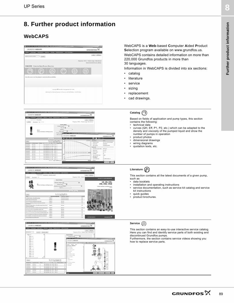
Fu
rth
er
pro
du
ct
info
rma
tio
n
UP Series 8
89
8. Further product information
WebCAPS
WebCAPS is a Web-based Computer Aided Product Selection program available on www.grundfos.us.
WebCAPS contains detailed information on more than 220,000 Grundfos products in more than 30 languages.
Information in WebCAPS is divided into six sections:
• catalog
• literature
• service
• sizing
• replacement
• cad drawings.
Catalog
Based on fields of application and pump types, this section contains the following:• technical data• curves (QH, Eff, P1, P2, etc.) which can be adapted to the
density and viscosity of the pumped liquid and show the number of pumps in operation
• product photos• dimensional drawings• wiring diagrams• quotation texts, etc.
Literature
This section contains all the latest documents of a given pump, such as• data booklets• installation and operating instructions• service documentation, such as service kit catalog and service
kit instructions• quick guides• product brochures.
Service
This section contains an easy-to-use interactive service catalog. Here you can find and identify service parts of both existing and discontinued Grundfos pumps.Furthermore, the section contains service videos showing you how to replace service parts.
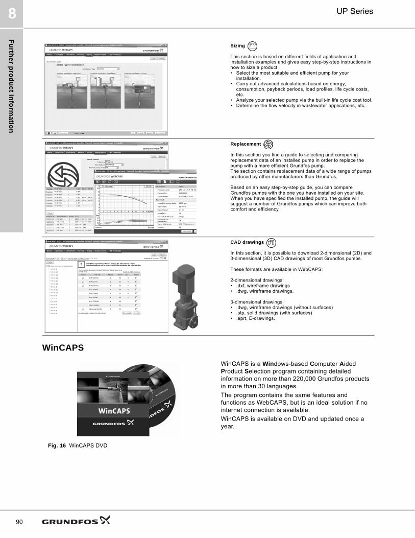
Fu
rthe
r pro
du
ct in
form
atio
n
UP Series8
90
WinCAPS
Fig. 16 WinCAPS DVD
Sizing
This section is based on different fields of application and installation examples and gives easy step-by-step instructions in how to size a product:• Select the most suitable and efficient pump for your
installation.• Carry out advanced calculations based on energy,
consumption, payback periods, load profiles, life cycle costs, etc.
• Analyze your selected pump via the built-in life cycle cost tool.• Determine the flow velocity in wastewater applications, etc.
Replacement
In this section you find a guide to selecting and comparing replacement data of an installed pump in order to replace the pump with a more efficient Grundfos pump. The section contains replacement data of a wide range of pumps produced by other manufacturers than Grundfos.
Based on an easy step-by-step guide, you can compare Grundfos pumps with the one you have installed on your site. When you have specified the installed pump, the guide will suggest a number of Grundfos pumps which can improve both comfort and efficiency.
CAD drawings
In this section, it is possible to download 2-dimensional (2D) and 3-dimensional (3D) CAD drawings of most Grundfos pumps.
These formats are available in WebCAPS:
2-dimensional drawings:• .dxf, wireframe drawings• .dwg, wireframe drawings.
3-dimensional drawings:• .dwg, wireframe drawings (without surfaces)• .stp, solid drawings (with surfaces)• .eprt, E-drawings.
WinCAPS is a Windows-based Computer Aided Product Selection program containing detailed information on more than 220,000 Grundfos products in more than 30 languages.
The program contains the same features and functions as WebCAPS, but is an ideal solution if no internet connection is available.
WinCAPS is available on DVD and updated once a year.
0 1

Fu
rth
er
pro
du
ct
info
rma
tio
n
UP Series 8
91
Grundfos GO
Mobile solution for professionals on the GO!
Grundfos GO is the mobile tool box for professional users on the go. It is the most comprehensive platform for mobile pump control and pump selection including sizing, replacement and documentation. It offers intuitive, handheld assistance and access to Grundfos online tools, and it saves valuable time for reporting and data collection.
GET IT ON
Subject to alterations.
Th
e n
am
e G
run
dfo
s, t
he
Gru
nd
fos
log
o,
an
d b
e t
hin
k i
nn
ov
ate
are
re
gis
tere
d t
rad
em
ark
s o
wn
ed
by
Gru
nd
fos
Ho
ldin
g A
/S o
r G
run
dfo
s A
/S,
De
nm
ark
. A
ll ri
gh
ts r
ese
rve
d w
orl
dw
ide
.©
Co
pyr
igh
t G
run
dfo
s H
old
ing
A/S
L-UP-PG-001
98532861 0614
ECM: 1133716
Grundfos Kansas City17100 West 118th TerraceOlathe, Kansas 66061Phone: 913-227-3400Fax: 913-227-3500www.grundfos.us
Grundfos Canada2941 Brighton RoadOakville, Ontario L6H 6C9 CanadaPhone: +1-905-829-9533Fax: +1-905-829-9512www.grundfos.ca
Grundfos MéxicoBoulevard TLC No. 15Parque Industrial Stiva AeropuertoC.P. 66600 Apodaca, N.L. MexicoPhone: 011-52-81-8144 4000Fax: 011-52-81-8144 4010www.grundfos.mx