UNVENTED (VENT-FREE) GAS LOG HEATER …fmisupport.hcents.com/supportdocs/WS 111826-04E1.pdf ·...
36
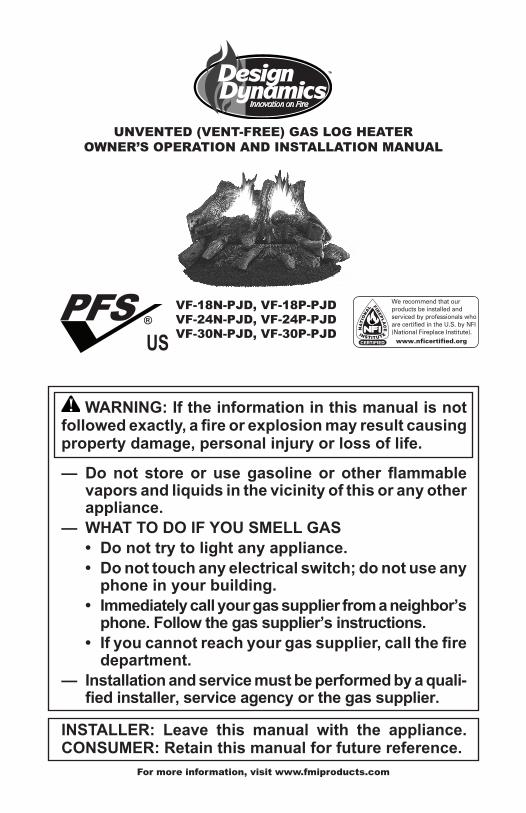
UNVENTED (VENT-FREE) GAS LOG HEATER OWNER’S OPERATION AND INSTALLATION MANUAL For more information, visit www.fmiproducts.com WARNING: If the information in this manual is not followed exactly, a fire or explosion may result causing property damage, personal injury or loss of life. — Do not store or use gasoline or other flammable vapors and liquids in the vicinity of this or any other appliance. — WHAT TO DO IF YOU SMELL GAS • Do not try to light any appliance. • Do not touch any electrical switch; do not use any phone in your building. • Immediately call your gas supplier from a neighbor’s phone. Follow the gas supplier’s instructions. • If you cannot reach your gas supplier, call the fire department. — Installation and service must be performed by a quali- fied installer, service agency or the gas supplier. INSTALLER: Leave this manual with the appliance. CONSUMER: Retain this manual for future reference. VF-18N-PJD, VF-18P-PJD VF-24N-PJD, VF-24P-PJD VF-30N-PJD, VF-30P-PJD PFS ® US
-
Upload
nguyentruc -
Category
Documents
-
view
216 -
download
0
Transcript of UNVENTED (VENT-FREE) GAS LOG HEATER …fmisupport.hcents.com/supportdocs/WS 111826-04E1.pdf ·...
UNVENTED (VENT-FREE) GAS LOG HEATEROWNER’S OPERATION AND INSTALLATION MANUAL
For more information, visit www.fmiproducts.com
WARNING: If the information in this manual is not followed exactly, a fire or explosion may result causing property damage, personal injury or loss of life.
— Do not store or use gasoline or other flammable vapors and liquids in the vicinity of this or any other appliance.
— WHAT TO DO IF YOU SMELL GAS• Do not try to light any appliance.• Do not touch any electrical switch; do not use any
phone in your building.• Immediately call your gas supplier from a neighbor’s
phone. Follow the gas supplier’s instructions.• If you cannot reach your gas supplier, call the fire
department.— Installation and service must be performed by a quali-
fied installer, service agency or the gas supplier.
INSTALLER: Leave this manual with the appliance. CONSUMER: Retain this manual for future reference.
VF-18N-PJD, VF-18P-PJDVF-24N-PJD, VF-24P-PJDVF-30N-PJD, VF-30P-PJD
PFS ®
US
www.fmiproducts.com 111826-04E2
SAFETy
WARNING: Improper installation, adjustment, alteration, service or maintenance can cause injury or property dam-age. Refer to this manual for correct installation and operational proce-dures. For assistance or additional information consult a qualified in-staller, service agency or the gas supplier.
WARNING: This ap-pliance is for installation only in a solid-fuel burning masonry or UL127 factory-built fireplace or in a listed ventless firebox enclo-sure. It is design-certified for these installations in accordance with ANSI Z21.11.2. Exception: Do not install this appliance in a factory-built fireplace that includes instructions stating it has not been test-ed or should not be used with unvented gas logs.
WARNING: This is an unvented gas-fired heat-er. It uses air (oxygen) from the room in which it is installed. Provisions for adequate combustion and ventilation air must be provided. Refer to Air for Combustion and Ven-tilation section on page 6 of this manual.
This appliance may be in-stalled in an aftermarket,* permanently located, manufactured (mobile) home, where not prohib-ited by local codes.
This appliance is only for use with the type of gas indicated on the rating plate. This appliance is not convertible for use with other gases.
* Aftermarket: Completion of sale, not for purpose of resale, from the manufacturer
TABLE OF CONTENTSSafety .................................................................. 2Product Identification ........................................... 5Local Codes......................................................... 5Unpacking............................................................ 5Product Features ................................................. 6Air For Combustion and Ventilation ..................... 6Installation ........................................................... 8Operation ........................................................... 16Inspecting Burners ............................................ 20Cleaning and Maintenance ................................ 21
Troubleshooting ................................................. 22Specifications .................................................... 25Service Hints ..................................................... 25Technical Service............................................... 25Replacement Parts ............................................ 26Accessories ....................................................... 26Wiring Diagram .................................................. 27Parts .................................................................. 28Warranty ..............................................Back Cover

www.fmiproducts.com111826-04E 3
WARNING: This product con-tains and/or generates chemicals known to the State of California to cause cancer or birth defects or other reproductive harm.
IMPORTANT: Read this owner’s manual carefully and completely before trying to assemble, operate or service this heater. Improper use of this heater can cause serious injury or death from burns, fire, explosion, electrical shock and carbon monoxide poisoning.
DANGER: Carbon monoxide poisoning may lead to death!
Carbon Monoxide Poisoning: Early signs of carbon monoxide poisoning resemble the flu, with headaches, dizziness or nausea. If you have these signs, the fireplace may not be working properly. Get fresh air at once! Have fireplace serviced. Some people are more af-fected by carbon monoxide than others. These include pregnant women, people with heart or lung disease or anemia, those under the influ-ence of alcohol and those at high altitudes.Natural and Propane/LP gases: Natural and Propane/LP gases are odorless. An odor-making agent is added to these gases. The odor helps you detect a gas leak. However, the odor added to the gas can fade. Gas may be present even though no odor exists.Make certain you read and understand all warnings. Keep this manual for reference. It is your guide to safe and proper operation of this fireplace.
WARNING: Any change to this heater or its controls can be dangerous.
WARNING: Do not use a blower insert, heat exchanger insert or other accessory not ap-proved for use with this heater.
SAFETyContinued
WARNING: Vent-free products are prohibited for bedroom and bathroom installation in the Com-monwealth of Massachusetts.
WARNING: Do not allow fans to blow directly into the heater. Avoid any drafts that alter burner flame patterns. Ceiling fans can create drafts that alter burner flame patterns. Altered burner patterns can cause sooting.
WARNING: Do not place log scraps or lava rocks on burner.
Due to high temperatures, the appliance should be located out of traffic and away from furniture and draperies.
Do not place clothing or other flammable material on or near the appliance. Never place any objects on the heater.
Heater base assembly becomes very hot when running heater. Keep children and adults away from hot surface to avoid burns or clothing ignition. Heater will remain hot for a time after shutdown. Allow surface to cool before touching.
Carefully supervise young chil-dren when they are in the room with heater. When using the hand-held remote accessory, keep se-lector switch in the OFF position to prevent children from turning on burners with remote.

www.fmiproducts.com 111826-04E4
SAFETy
You must operate this heater with a fireplace doors or screen in place and fully closed. Un-less provided by other means, screens shall have openings for introduction of combustion air.
Keep the appliance area clear and free from combustible ma-terials, gasoline and other flam-mable vapors and liquids.
1. This appliance is only for use with the type of gas indicated on the rating plate. This appliance is not convertible for use with other gases.
2. Do not place propane/LP supply tank(s) inside any structure. Locate propane/LP supply tank(s) outdoors (propane/LP units only).
3. If you smell gas• shut off gas supply• do not try to light any appliance• do not touch any electrical switch; do not
use any phone in your building• immediately call your gas supplier from
a neighbor’s phone. Follow the gas sup-plier’s instructions
• if you cannot reach your gas supplier, call the fire department
4. This heater shall not be installed in a bedroom or bathroom unless installed as a vented appliance.
5. Before installing in a solid fuel burning fire-place, the chimney flue and firebox must be cleaned of soot, creosote, ashes and loose paint by a qualified chimney cleaner. Creosote will ignite if highly heated. A dirty chimney flue may create an distribute soot within the house. Inspect chimney flue for damage. If damaged, repair flue before operating heater.
6. Do not burn solid fuel in a masonry or UL127 factory-built fireplace in which a vent-free room heater is installed.
7. If fireplace has glass doors, never operate this heater with glass doors closed. If you operate heater with doors closed, heat buildup inside fireplace will cause glass to burst. Make sure there are no obstructions across openings of fireplace.
8. To prevent the creation of soot, follow the instructions in Cleaning and Maintenance, page 21.
9. Before using furniture polish, wax, carpet cleaner or similar products, turn heater off. If heated, the vapors from these products may create a white powder residue within burner box or on adjacent walls or furni-ture.
10. This heater needs fresh, outside air ven-tilation to run properly. This heater has an oxygen depletion sensing (ODS) pilot light safety system. The ODS shuts down the heater if not enough fresh air is available. See Air for Combustion and Ventilation, page 6. If heater keeps shutting off, see Troubleshooting, page 22.
11. Do not run heater• where flammable liquids or vapors are
used or stored• under dusty conditions
12. Do not use this heater to cook food or burn paper or other objects.
13. Do not use heater if any part has been exposed to or under water. Immediately call a qualified service technician to inspect the room heater and to replace any part of the control system and any gas control which has been under water.
14. Do not operate heater if any log is broken. Do not operate heater if a log is chipped (dime-sized or larger).
15. Turn heater off and let cool before servic-ing or repairing. Make sure the selector switch is in the OFF position. Only a quali-fied service person should install, service or repair heater.
16. Make sure selector switch is in the OFF position when you are away from home for long periods of time.
17. This heater does not need to be con-nected to any external electrical source.
18. To prevent performance problems, do not use propane/LP fuel tank of less than 100 lb. capacity (propane/LP units only).
19. Provide adequate clearances around air openings.
www.fmiproducts.com111826-04E 5
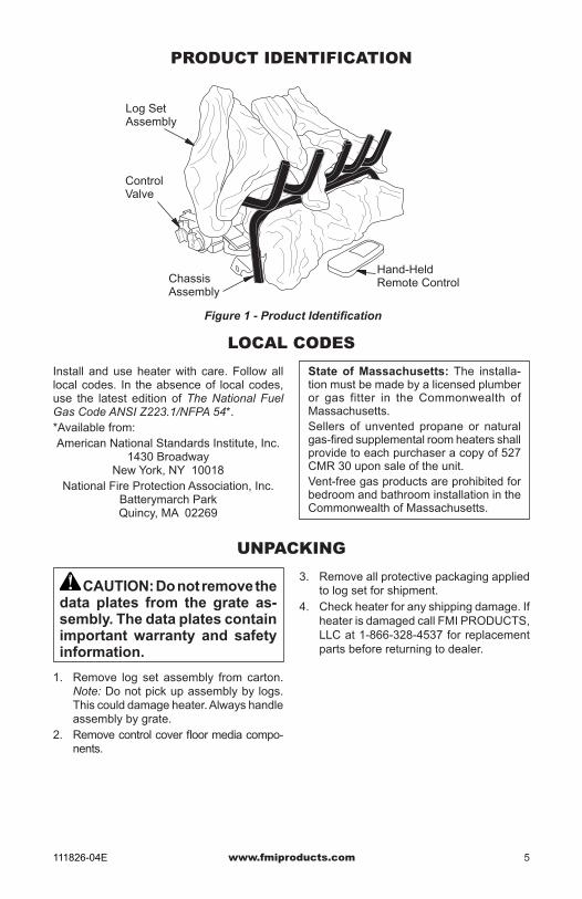
PRODUCT IDENTIFICATION
Figure 1 - Product Identification
LOCAL CODES
State of Massachusetts: The installa-tion must be made by a licensed plumber or gas fitter in the Commonwealth of Massachusetts.Sellers of unvented propane or natural gas-fired supplemental room heaters shall provide to each purchaser a copy of 527 CMR 30 upon sale of the unit.Vent-free gas products are prohibited for bedroom and bathroom installation in the Commonwealth of Massachusetts.
UNPACkING
Install and use heater with care. Follow all local codes. In the absence of local codes, use the latest edition of The National Fuel Gas Code ANSI Z223.1/NFPA 54*.*Available from:American National Standards Institute, Inc.
1430 BroadwayNew York, NY 10018
National Fire Protection Association, Inc.Batterymarch ParkQuincy, MA 02269
Hand-Held Remote ControlChassis
Assembly
ControlValve
Log Set Assembly
CAUTION: Do not remove the data plates from the grate as-sembly. The data plates contain important warranty and safety information.
1. Remove log set assembly from carton. Note: Do not pick up assembly by logs. This could damage heater. Always handle assembly by grate.
2. Remove control cover floor media compo-nents.
3. Remove all protective packaging applied to log set for shipment.
4. Check heater for any shipping damage. If heater is damaged call FMI PRODUCTS, LLC at 1-866-328-4537 for replacement parts before returning to dealer.

www.fmiproducts.com 111826-04E6
AIR FOR COMBUSTION AND VENTILATION
PRODUCT FEATURES
OPERATIONThis heater is clean burning. It requires no out-side venting. There is no heat loss out a vent or up a chimney. Heat is generated by realistic flames and glowing ceramic logs/coals. This heater is designed for vent-free operation with flue damper closed. It has been tested and ap-proved to ANSI Z21.11.2 standard for unvented heaters. State and local codes in some areas prohibit the use of vent-free heaters.
SAFETY DEvICEThis heater has a pilot with an Oxygen Deple-tion Sensing (ODS) safety shutoff system. The ODS/pilot is a required feature for vent-free room heaters. The ODS/pilot shuts off the heater if there is not enough fresh air.
REMOTE IGNITION AND CONTROLThis gas log set has a battery powered electronic remote ignition and control. This system requires no matches or other source to light log set.
WARNING: This heater shall not be installed in a room or space unless the required volume of indoor combustion air is provided by the method described in the National Fuel Gas Code, ANSI Z223.1/NFPA 54, the International Fuel Gas Code, or applicable local codes. Read the following instructions to insure proper fresh air for this and other fuel-burning appliances in your home.
Today’s homes are built more energy efficient than ever. New materials, increased insulation and new construction methods help reduce heat loss in homes. Home owners weather strip and caulk around windows and doors to keep the cold air out and the warm air in. During heating months, home owners want their homes as airtight as possible.While it is good to make your home energy efficient, your home needs to breathe. Fresh air must enter your home. All fuel-burning ap-pliances need fresh air for proper combustion and ventilation.Exhaust fans, fireplaces, clothes dryers and fuel burning appliances draw air from the house to operate. You must provide adequate fresh air for these appliances. This will insure proper venting of vented fuel-burning appliances.
PROVIDING ADEQUATE vENTILATION The following are excerpts from National Fuel Gas Code, ANSI Z223.1/NFPA 54, Air for Combustion and Ventilation.
All spaces in homes fall into one of the three following ventilation classifications:1. Unusually Tight Construction2. Unconfined Space3. Confined SpaceThe information on pages 6 through 8 will help you classify your space and provide adequate ventilation.
Unusually Tight ConstructionThe air that leaks around doors and windows may provide enough fresh air for combus-tion and ventilation. However, in buildings of unusually tight construction, you must provide additional fresh air.Unusually tight construction is defined as construction where:a. walls and ceilings exposed to the out-
side atmosphere have a continuous water vapor retarder with a rating of one perm (6 x 10-11 kg per pa-sec-m2) or less with openings gasketed or sealed and
b. weather stripping has been added on openable windows and doors and
c. caulking or sealants are applied to areas such as joints around window and door frames, between sole plates and floors, between wall-ceiling joints, between wall panels, at penetrations for plumbing, electrical and gas lines and at other openings.
If your home meets all of the three criteria above, you must provide additional fresh air. See Ventilation Air From Outdoors, page 8. If your home does not meet all of the three criteria above, proceed to Determin-ing Fresh-Air Flow For Heater Location, page 7.

www.fmiproducts.com111826-04E 7
AIR FOR COMBUSTION AND VENTILATIONContinued
40,00033,00073,000
Confined and Unconfined SpaceThe National Fuel Gas Code, ANSI Z223.1/NFPA 54 defines a confined space as a space whose volume is less than 50 cubic feet per 1,000 Btu per hour (4.8 m3 per kw) of the ag-gregate input rating of all appliances installed in that space and an unconfined space as a space whose volume is not less than 50 cubic feet per 1,000 Btu per hour (4.8 m3 per kw) of the ag-gregate input rating of all appliances installed in that space. Rooms communicating directly with the space in which the appliances are installed*, through openings not furnished with doors, are considered a part of the unconfined space.* Adjoining rooms are communicating only if there are doorless passageways or ventilation grills between them.
DETERMINING FRESH-AIR FLOW FOR HEATER LOCATIONDetermining if You Have a Confined or Unconfined SpaceUse this work sheet to determine if you have a confined or unconfined space.Space: Includes the room in which you will install heater plus any adjoining rooms with doorless passageways or ventilation grills between the rooms.1. Determine the volume of the space (length
x width x height). Length x Width x Height =__________cu. ft.
(volume of space) Example: Space size 20 ft. (length) x 16 ft.
(width) x 8 ft. (ceiling height) = 2,560 cu. ft. (volume of space)
If additional ventilation to adjoining room is sup-plied with grills or openings, add the volume of these rooms to the total volume of the space.
2. Multiply the space volume by 20 to determine the maximum Btu/Hr the space can support.
________ (volume of space) x 20 = (Maxi-mum Btu/Hr the space can support)
Example: 2,560 cu. ft. (volume of space) x 20 = 51,200 (maximum Btu/Hr the space can support)
3. Add the Btu/Hr of all fuel burning appliances in the space.
Vent-free fireplace _________ Btu/Hr Gas water heater* _________ Btu/Hr Gas furnace _________ Btu/Hr Vented gas heater _________ Btu/Hr Gas fireplace logs _________ Btu/Hr Other gas appliances* + ________ Btu/Hr Total = _________ Btu/Hr
* Do not include direct-vent gas appliances. Direct-vent draws combustion air from the outdoors and vents to the outdoors.
Example: Gas water heater _________ Btu/Hr Vent-free fireplace + _________ Btu/Hr Total = _________ Btu/Hr4. Compare the maximum Btu/Hr the space
can support with the actual amount of Btu/Hr used.
_______ Btu/Hr (maximum the space can sup-port)
________ Btu/Hr (actual amount of Btu/Hr used)
Example: 51,200 Btu/Hr (maximum the space can support)
73,000 Btu/Hr (actual amount of Btu/Hr used)
The space in the above example is a confined space because the actual Btu/Hr used is more than the maximum Btu/Hr the space can sup-port. You must provide additional fresh air. Your options are as follows:A. Rework worksheet, adding the space of an
adjoining room. If the extra space provides an unconfined space, remove door to adjoin-ing room or add ventilation grills between rooms. See Ventilation Air From Inside Building, page 8.
B. Vent room directly to the outdoors. See Ventilation Air From Outdoors, page 8.
C. Install a lower Btu/Hr fireplace, if lower Btu/Hr size makes room unconfined.
If the actual Btu/Hr used is less than the maxi-mum Btu/Hr the space can support, the space is an unconfined space. You will need no additional fresh air ventilation.
WARNING: If the area in which the heater may be oper-ated does not meet the required volume for indoor combustion air, combustion and ventilation air shall be provided by one of the methods described in the National Fuel Gas Code, ANSI Z223.1/NFPA 54, the Internation-al Fuel Gas Code, or applicable local codes.

www.fmiproducts.com 111826-04E8
AIR FOR COMBUSTION AND VENTILATION
Figure 3 - Ventilation Air from Outdoors
OutletAir
VentilatedAttic
OutletAir
InletAir
Inlet Air Ventilated Crawl Space
To CrawlSpace
To Attic
INSTALLATION
WARNING: Make sure the selector switch is in the OFF po-sition before installing heater.
vENTILATION AIRVentilation Air From Inside Building This fresh air would come from an adjoining un-confined space. When ventilating to an adjoining unconfined space, you must provide two perma-nent openings: one within 12" of the ceiling and one within 12" of the floor on the wall connecting the two spaces (see options 1 and 2, Figure 2). You can also remove door into adjoining room (see option 3, Figure 2). Follow the National Fuel Gas Code, ANSI Z223.1/NFPA 54, Air for Combustion and Ventilation for required size of ventilation grills or ducts.
OrRemoveDoor intoAdjoining
Room,Option
3
Ventilation Grills Into Adjoining Room,
Option 2
VentilationGrills
Into Adjoining Room,
Option 1
12"
12"
ventilation Air From OutdoorsProvide extra fresh air by using ventilation grills or ducts. You must provide two perma-nent openings: one within 12" of the ceiling and one within 12" of the floor. Connect these items directly to the outdoors or spaces open to the outdoors. These spaces include attics and crawl spaces. Follow the National Fuel Gas Code, ANSI Z223.1/NFPA 54, Air for Combustion and Ventilation for required size of ventilation grills or ducts. IMPORTANT: Do not provide openings for inlet or outlet air into attic if attic has a thermo-stat-controlled power vent. Heated air entering the attic will activate the power vent.
Figure 2 - Ventilation Air from Inside Building
NOTICE: This heater is intended for use as supplemental heat. Use this heater along with your primary heating system. Do not install this heater as your pri-mary heat source. If you have a central heating system, you may run system’s circulating blower while using heater. This will help circulate the heat throughout the house. In the event of a power outage, you can use this heater as your primary heat source.
WARNING: A qualified ser-vice person must install heater. Follow all local codes.
NOTICE: State or local codes may only allow operation of this appli-ance in a vented configuration. Check your state or local codes.
WARNING: Seal any fresh air vents or ash clean-out doors located on floor or wall of fire-place. If not, drafting may cause pilot outage or sooting. Use a heat-resistant sealant. Do not seal chimney flue damper.
www.fmiproducts.com111826-04E 9
IMPORTANT: Vent-free heaters add moisture to the air. Although this is beneficial, installing heater in rooms without enough ventilation air may cause mildew to form from too much moisture. See Air for Combustion and Ventila-tion, page 6.
INSTALLATIONContinued
Carefully follow the instructions below. This will ensure safe installation into a masonry, UL127-listed manufactured fireplace or listed vent-free firebox enclosure.
Minimum Clearances For Side Combustible Material, Side Wall and Ceiling A. Clearances from the side of the fireplace
cabinet to any combustible material and wall should follow diagram in Figure 4, page 10.
Example: The face of a mantel, bookshelf, etc. is made of combustible material and protrudes 3 1/2" from the wall. This combustible material must be 4" from the side of the fireplace cabinet (see Figure 4, page 10).
LOG SIZING REQUIREMENTSMinimum Firebox Size Center
Log Size Height Depth
Front
Width
Rear*
Width
18" 17" 14" 24" 20"
24" 17" 14" 28" 22"
30" 24" 17 1/2" 42" 28 3/4"
*Measured at 14" depth
WARNING: Before installing in a solid fuel burning fireplace, the chimney flue and firebox must be cleaned of soot, creo-sote, ashes and loose paint by a qualified chimney cleaner. Creosote will ignite if highly heated. A dirty chimney flue may create and distribute soot within the house. Inspect chimney and firebox flue for damage. If dam-aged, repair flue and firebox before operating heater.
WARNING: Never install the heater• in a bedroom or bathroom un-
less installed as a vented unit, see page 12
• in a recreational vehicle• where curtains, furniture, cloth-
ing or other flammable objects are less than 42" from the front, top or sides of the heater
• in high traffic areas• in windy or drafty areas
CAUTION: This heater cre-ates warm air currents. These currents move heat to wall sur-faces next to heater. Installing heater next to vinyl or cloth wall coverings or operating heater where impurities (such as, but not limited to, tobacco smoke, aromatic candles, cleaning flu-ids, oil or kerosene lamps, etc.) in the air exist, may discolor walls or cause odors.
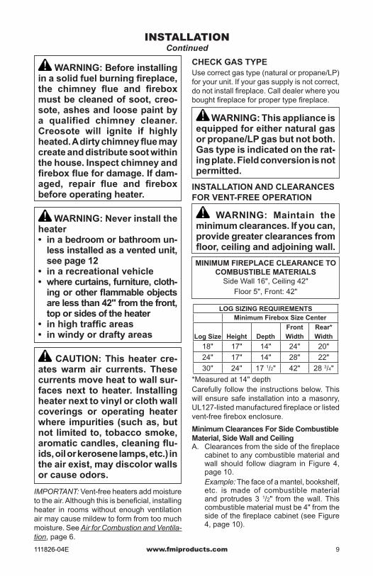
CHECK GAS TYPEUse correct gas type (natural or propane/LP) for your unit. If your gas supply is not correct, do not install fireplace. Call dealer where you bought fireplace for proper type fireplace.
WARNING: This appliance is equipped for either natural gas or propane/LP gas but not both. Gas type is indicated on the rat-ing plate. Field conversion is not permitted.
INSTALLATION AND CLEARANCES FOR VENT-FREE OPERATION
WARNING: Maintain the minimum clearances. If you can, provide greater clearances from floor, ceiling and adjoining wall.
MINIMUM FIREPLACE CLEARANCE TO COMBUSTIBLE MATERIALS
Side Wall 16", Ceiling 42"Floor 5", Front: 42"

www.fmiproducts.com 111826-04E10
INSTALLATIONContinued
Note: When installing your gas logs into a manufactured firebox, follow firebox manufacturer’s instructions for minimum clearances to combustible materials.
B. Clearances from the top of the fireplace opening to the ceiling should not be less than 42".
Figure 4 - Minimum Clearance for Combustible to Wall
*Minimum 16" from Side Wall
*
Example
Minimum Noncombustible Material Clearances
If Not Using MantelNote: If using a mantel proceed to If Using Mantel. If not using a mantel, follow these instructions. You must have noncombustible material(s) above the fireplace opening. Noncombustible materials (such as slate, marble, tile, etc.) must be at least 1/2" thick. With sheet metal, you must have noncombustible material behind it. Noncombustible material must extend at least 8" up (for all models). If noncombustible material is less than 12", you must install the fireplace hood accessory (24" Model Only). See Figure 5 for minimum clearances.
Heat ResistantMaterial
(A)
Figure 5 - Heat Resistant Material (Slate, Marble, Tile, etc.) Above Fireplace
Noncombustible Material Distance (A)
Requirements for Safe Installation
12" or more Noncombustible mate-rial OK.
Between 8" and 12" 24" or 30" Models: Install fireplace hood accessory (GA6050, GA6052 or GA6053 see Accessories, page 26).18" Model: Noncom-bustible material OK.
Less than 8" Noncombustible mate-rial must be extended to at least 8". See Between 8" and 12", above. If you cannot extend material, you must operate heater with flue damper open.
If Using MantelYou must have noncombustible material(s) above the fireplace opening. Noncombus-tible materials (such as slate, marble, tile, etc.) must be at least 1/2" thick. With sheet metal, you must have noncombustible ma-terial behind it. Noncombustible material must extend at least 8" up (for all models). If noncombustible material is less than 12", you must install the fireplace hood accessory (24" Model Only). Even if noncombustible material is more than 12", you may need the hood ac-cessory to deflect heat away from your mantel shelf. See Figure 5 and Figures 6 and 7, page 11, for minimum clearances. IMPORTANT: If you cannot meet these mini-mum clearances, you must operate heater with chimney flue damper open. Go to Install-ing Damper Clamp Accessory for Vented Operation, page 12.

www.fmiproducts.com111826-04E 11
INSTALLATIONContinued
MANTEL CLEARANCESIn addition to meeting noncombustible mate-rial clearances, you must also meet required clearances between fireplace opening and mantel shelf. If you do not meet the clearances listed below, you will need a hood.
Determining Minimum Mantel ClearanceIf you meet minimum clearance between mantel shelf and top of fireplace opening, a hood is not required (see Figure 6).
Figure 6 - Minimum Mantel Clearances Without Using Hood
14"Min.
Combustible Material
Noncombustible Material
Figure 8 - Minimum Fireplace Clearances If Installed at Floor Level
Figure 7 - Minimum Mantel Clearances When Using Hood
Minimum Non-Combustible Material
Minimum Non-Combustible Material Height
Distances to Underside ofMantel
Top of FireplaceOpening
Underside ofMantel Shelf
12"
8"
(A)
18"
14"
20"
17"
22"
19"
24"
20"
All minimum distances arein inches
Log Set24"/30"/36" Models18" Model
2 1/2"6"8"10"
Mantel Shelf
MinimumNoncombustible Material
8"Min.
12" 15" 18"
Log Sets18", 24",
& 30"Models
20"
2 1/2"
6"
8"
10"
12"
Distances to Underside of
Mantel
Hood (GA6050, GA6052,
or GA6053)
Top ofFireplaceOpening
Undersideof Mantel
Shelf
Mantel Shelf
Hearth
5"Min.
Combustible Material
Figure 9 - Minimum Fireplace Clearances Above Combustible Flooring
NOTICE: Surface temperatures of adjacent walls and mantels be-come hot during operation. Walls and mantels above the firebox may become hot to the touch. If installed properly, these tem-peratures meet the requirement of the national product standard. Follow all minimum clearances shown in this manual.
NOTICE: If your installation does not meet the minimum clear-ances shown, you must do one of the following: • operate the logs only with the
flue damper open• raise the mantel to an accept-
able height• remove the mantel
FLOOR CLEARANCESA. If installing appliance on the floor level,
you must maintain the minimum distance of 14" to combustibles (see Figure 8).
B. If combustible materials are less than 14" to the fireplace, you must install appliance at least 5" above the combustible flooring (see Figure 9).
Determining Minimum Mantel Clearance When Using a HoodIf minimum clearances in Figure 6, are not met, you must have a hood. When using a hood there are still certain minimum mantel clearances required. Follow minimum clear-ances shown in Figure 7, when using hood.

www.fmiproducts.com 111826-04E12
INSTALLATIONContinued
INSTALLING DAMPER CLAMP ACCESSORY FOR vENTED OPERATIONNote: When used as a vented heater, ap-pliance must be installed only in a solid-fuel burning fireplace with a working flue and con-structed of noncombustible material.For Massachusetts Residents Only: Instal-lation of this gas log set as a vented appliance in the Commonwealth of Massachusetts re-quires the damper be permanently removed or welded in the fully open position.If your heater is a non-thermostatically-controlled model, you may use this heater as a vented product. There are three reasons for operating your heater in the vented mode.1. The fireplace does not meet the clearance
to combustibles requirements for vent-free operation.
2. State or local codes do not permit vent-free operation.
3. You prefer vented operation.If reasons number 1 or 2 above apply to you, you must permanently open chimney flue damper. You must install the damper clamp accessory (to order, see Accessories, page 26). This will insure vented operation (see Fig-ure 10). The damper clamp will keep damper open. Installation instructions are included with clamp accessory.See chart below for minimum permanent flue opening you must provide. Attach damper clamp so the minimum permanent flue open-ing will be maintained at all times.
Area of various Standard Round Flues Diameter Area 5" 20 sq. inches 6" 29 sq. inches 7" 39 sq. inches 8" 51 sq. inches
Chimney Minimum Permanent Height Flue Opening 6' to 15' 39 sq. inches 15' to 30' 29 sq. inches
Damper
Damper Clamp
Damper
Damper Clamp
Damper
Figure 10 - Attaching Damper Clamp
Manufactured FireplaceMasonry Fireplace
INSTALLING HEATER ASSEMBLY
CAUTION: Do not remove the data plates attached to the heater base assembly. The data plates contain important warranty and safety information.
WARNING: If installing in a sunken fireplace, special care is needed. You must raise the fireplace floor to allow access to heater control panel. This will in-sure adequate air flow and guard against sooting and controls be-ing damaged. Raise fireplace floor with noncombustible material. Make sure material is secure.
CAUTION: Do not pick up heater assembly by the logs. This could damage heater. Only han-dle base assembly by grates.
IMPORTANT: Make sure the heater burner is level. If heater is not level, heater will not work properly.

www.fmiproducts.com111826-04E 13
CONNECTING TO GAS SUPPLY
WARNING: This appliance requires a 1/2" NPT (National Pipe Thread) inlet connection to the pressure regulator.
WARNING: A qualified service person must connect heater to gas supply. Follow all local codes.
CAUTION: Never connect propane/LP fireplace directly to the propane/LP supply. This heater requires an external regu-lator (not supplied). Install the external regulator between the heater and propane/LP supply.
Figure 11 - Attaching Flexible Gas Hose to Heater Gas Regulator
Installation Items Needed• control cover kit (provided with heater)• approved flexible gas hose (provided) (if
allowed by local codes) • sealant (resistant to propane/LP gas, not
provided)• pipe wrench1. Apply pipe joint sealant lightly to male
threads of gas fitting (not provided). Connect approved flexible gas hose to inlet side of gas control (see Figure 11). IMPORTANT: Hold gas fitting with wrench when connecting flexible gas hose.
2. Position heater assembly in fireplace.3. Connect to gas supply. See Connecting
to Gas Supply.
INSTALLATIONContinued
WARNING: Never connect natural gas fireplace to private (non-utility) gas wells. This gas is commonly known as wellhead gas.
Installation Items NeededBefore installing heater, make sure you have the items listed below.• external regulator (for propane/LP units
only, supplied by installer)• piping (check local codes)• sealant (resistant to propane/LP gas)• equipment shutoff valve *• test gauge connection *• sediment trap• tee joint• pipe wrench• approved flexible gas line with gas connec-
tor (if allowed by local codes) (provided) * A CSA design-certified equipment shutoff valve with 1/8" NPT tap is an acceptable al-ternative to test gauge connection. Purchase the optional CSA design-certified equipment shutoff valve from your dealer.
Figure 12 - External Regulator With Vent Pointing Down
Propane/LP Supply Tank
External Regulator
Vent Pointing Down
For propane/LP units, the installer must supply an external regulator. The external regulator will reduce incoming gas pressure. You must reduce incoming gas pressure to between 11" and 14" of water. If you do not reduce incoming gas pressure, heater regulator damage could occur. Install exter-nal regulator with the vent pointing down as shown in Figure 12. Pointing the vent down protects it from freezing rain or sleet.
Fitting
Flexible Gas Hose (if allowed by local codes)

www.fmiproducts.com 111826-04E14
INSTALLATIONContinued
* Purchase the optional CSA design-certified equipment shutoff valve from your dealer.** Minimum inlet pressure for purpose of input adjustment.
Figure 13 - Gas Connection
3" Minimum
CSA Design-Certified Equipment Shutoff Valve With 1/8" NPT Tap*
Approved Flexible Gas Hose (if allowed by local codes)
Cap Pipe Tee Nipple Joint
Sediment Trap
Natural GasFrom Gas Meter
(5" W.C.** to 10.5" W.C. Pressure)
Propane/LP GasFrom External
Regulator(11" W.C.** to
14" W.C.Pressure)
To Gas Control
WARNING: Use pipe joint sealant that is resistant to liquid petroleum (LP) gas.
We recommend that you install a sediment trap in supply line as shown in Figure 13. Locate sediment trap where it is within reach for cleaning. Install in piping system between fuel supply and heater. Locate sediment trap where trapped matter is not likely to freeze. A sediment trap traps moisture and contaminants. This keeps them from going into heater controls. If sediment trap is not installed or is installed wrong, heater may not run properly.
CAUTION: Avoid damage to gas control. Hold gas control with wrench when connecting it to gas piping and/or fittings.
CHECkING GAS CONNECTIONS
WARNING: Test all gas piping and connections, internal and external to unit, for leaks after installing or servicing. Correct all leaks at once.
WARNING: Never use an open flame to check for a leak. Apply a noncorrosive leak detec-tion fluid to all joints. Bubbles forming show a leak. Correct all leaks at once.
CAUTION: Make sure exter-nal regulator has been installed between propane/LP supply and heater. See guidelines un-der Connecting to Gas Supply, page 13.
CAUTION: Use only new, black iron or steel pipe. Inter-nally-tinned copper tubing may be used in certain areas. Check your local codes. Use pipe of 1/2" diameter or greater to allow proper gas volume to heater. If pipe is too small, undue loss of volume will occur.
Installation must include an equipment shutoff valve, union and plugged 1/8" NPT tap. Locate NPT tap within reach for test gauge hook up. NPT tap must be upstream from heater (see Figure 13).IMPORTANT: Install equipment shutoff valve in an accessible location. The equipment shutoff valve is for turning on or shutting off the gas to the appliance.
Check your building codes for any special requirements for locating equipment shutoff valve to fireplaces.Apply pipe joint sealant lightly to male NPT threads. This will prevent excess sealant from going into pipe. Excess sealant in pipe could result in clogged heater valves.

www.fmiproducts.com111826-04E 15
PRESSURE TESTING GAS SUPPLY PIPING SYSTEMTest Pressures In Excess Of 1/2 PSIG (3.5 kPa)1. Disconnect appliance with its appliance
main gas valve (control valve) and equip-ment shutoff valve from gas supply piping system. Pressures in excess of 1/2 psig will damage heater regulator.
2. Cap off open end of gas pipe where equip-ment shutoff valve was connected.
3. Pressurize supply piping system by either opening propane/LP supply tank valve for propane/LP gas or opening main gas valve located on or near gas meter for natural gas or using compressed air.
4. Check all joints of gas supply piping sys-tem. Apply noncorrosive leak detection fluid to all joints. Bubbles forming show a leak.
5. Correct all leaks at once.6. Reconnect heater and equipment shutoff
valve to gas supply. Check reconnected fittings for leaks.
Test Pressures Equal To or Less Than 1/2 PSIG (3.5 kPa)1. Close equipment shutoff valve (see
Figure 14).2. Pressurize supply piping system by either
opening propane/LP supply tank valve for propane/LP gas or opening main gas valve located on or near gas meter for natural gas or using compressed air.
3. Check all joints from gas meter to equip-ment shutoff valve for natural gas or propane/LP supply to equipment shutoff valve for propane/LP (see Figure 15 or 16). Apply noncorrosive leak detection fluid to all joints. Bubbles forming show a leak.
4. Correct all leaks at once.
INSTALLATIONContinued
Figure 14 - Equipment Shutoff Valve
Open
Closed
Equipment Shutoff Valve
Figure 15 - Checking Gas Joints for Natural Gas
PRESSURE TESTING HEATER GAS CONNECTIONS1. Open equipment shutoff valve (see
Figure 14).2. Open main gas valve located on or near
gas meter for natural gas or open pro-pane/LP supply tank valve.
3. Make sure control knob of heater is in the OFF position.
4. Check all joints from equipment shutoff valve to control valve (see Figure 15 or 16). Apply noncorrosive leak detection fluid to all joints. Bubbles forming show a leak.
5. Correct all leaks at once.6. Light heater (see Operation, page 16).
Check all other internal joints for leaks.7. Turn off heater (see To Turn Off Gas to
Appliance, page 18 or 19).
Figure 16 - Checking Gas Joints (Propane/LP Only)
Gas Meter
Equipment Shutoff Valve
Control Valve Location
Control Valve Location
Propane/LP Supply Tank
Equipment Shutoff Valve

www.fmiproducts.com 111826-04E16
FOR YOUR SAFETY READ BEFORE LIGHTING
WARNING: If you do not fol-low these instructions exactly, a fire or explosion may result causing property damage, per-sonal injury or loss of life.
A. This appliance has a pilot which must be lighted by hand. When lighting the pilot, follow these instructions exactly.
B. BEFORE LIGHTING smell all around the appliance area for gas. Be sure to smell next to the floor because some gas is heavier than air and will settle on the floor.
WHAT TO DO IF YOU SMELL GAS• Do not try to light any appliance.
OPERATION
REMOTE LIGHTING INSTRUCTIONS CAUTION: A mild gas flash
within 10 seconds is normal during shutdown of this heater. Remain clear of the hearth area for the entire shutdown process to avoid possible injury.
1. STOP! Read the safety information above.
2. Make sure equipment shutoff valve is fully open.
3. Turn motor knob clockwise to the OFF position.
4. Wait five (5) minutes to clear out any gas. Then smell for gas, including near the floor. If you smell gas, STOP! Follow “B” in the safety information. If you don’t smell gas, go to the next step.
5. Make sure ON/OFF switch is in "–" (ON) position.
WARNING: Burner will come on automatically within one minute after pilot burner is lighted.
• Do not touch any electric switch; do not use any phone in your building.
• Immediately call your gas supplier from a neighbor’s phone. Follow the gas supplier’s instructions.
• If you cannot reach your gas sup-plier, call the fire department.
C. Use only your hand to push in or turn the gas control knob. Never use tools. If the knob will not push in or turn by hand, don’t try to repair it, call a qualified service technician or gas supplier. Force or attempted repair may result in a fire or explosion.
D. Do not use this appliance if any part has been under water. Immediately call a qualified service technician to inspect the appliance and to replace any part of the control system and any gas control which has been under water.
REMOTE OPERATION
WARNING:• If fireplace has glass doors,
never operate this heater with glass doors closed. If you op-erate heater with doors closed, heat buildup inside fireplace will cause glass to burst. Make sure there are no obstructions across openings of fireplace.
• You must operate this heater with a fireplace screen in place. Make sure fireplace screen is closed before running heater.
NOTICE: During initial operation of new heater, burning logs will give off a paper-burning smell. Orange flame will also be pres-ent. Open damper or window to vent smell. This will only last a few hours.
www.fmiproducts.com111826-04E 17
OPERATIONContinued
REMOTE OPERATION
6. Press the buttons and at the same time. A short acoustic signal confirms the start sequence has begun.
Further short acoustic signals (0.2 sec., 1 Hz) indicate the ignition process until it is completed and main gas flows. If pilot is already lit, motor will turn on (max. flame height) while buttons are pressed down. If pilot does not light, see Troubleshooting, page 22.
7. Press to turn on main burner and increase flame height. Press to de-crease flame height and shut off main burner.
8. Short tapping of either button allows incremental change in flame height.
9. Press OFF button to switch off main gas and pilot gas.
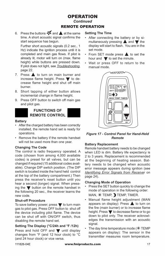
FUNCTIONS OF REMOTE CONTROL
Battery• After the charged battery has been correctly
installed, the remote hand set is ready for operations.
• Remove the battery if the remote handset will not be used more than one year.
Changing The CodeThe control is radio frequency operated. A code (chosen from among 4,000 available codes) is preset for all valves, but can be changed if required (15 additional codes avail-able). Change DIP switch position. (The DIP switch is located inside the hand held control at the top of the battery compartment.) Then press the receiver's reset button until you hear a second (longer) signal. When press-ing the button on the remote handset in the following 20 sec., the receiver learns the new code.
SET
OFFSTAND
BY
Figure 17 - Control Panel for Hand-Held Remote
Battery ReplacementRemote handset battery needs to be changed when LED is dim. Battery life expectancy is 2 to 3 years. Replacement is recommended at the beginning of heating season. Bat-tery needs to be changed when acoustic error message appears during ignition (see Identifying Error Signals from Receiver on page 24).
Changing Mode of Operation• Press the SET button quickly to change the
mode of operation in the following order: MAN, TEMP, TEMP, TIMER.• Manual flame height adjustment (MAN
appears on display): Press to turn on the fire (main burner) or to increase flame height. Press to decrease flame or to go down to pilot only. The receiver acknowl-edges the transmission with an acoustic signal.
• The day time temperature mode ( TEMP appears on display): The sensor in the transmitter measures room temperature.
Setting The Time• After connecting the battery or by si-
multaneously pressing and the display will start to flash. You are in the set mode.
• From SET mode press to set the hour and to set the minute.
• Wait or press OFF to return to the manual mode.
Shut-off ProcedureTo save battery power; press to turn main gas to pilot gas. Press OFF button to shut off the device including pilot flame. The device can be shut off with ON/OFF switch, thus disabling the remote hand set.
Setting The Display ( °C/24h and °F /12h)Press and hold OFF and until display changes from °F (and 12 hour clock) to °C (and 24 hour clock) or vice versa.
www.fmiproducts.com 111826-04E18
OPERATIONContinued
The controller compares the room tem-perature with set temperature and sends a signal to the receiver to turn the gas valve motor up or down, to adjust the flame height accordingly.
• The nighttime setback temperature ( TEMP appears on display): The sensor in the transmitter measures the temperature and adjusts it according to the nighttime setback temperature. There is a bigger temperature differential during this cycle.
• Timer: The timer mode ( TIMER ) operates much like the temperature mode above. The timer setting allows you to set specific times for on and off. (There are 2 burner on and 2 burner off cycles every 24 hours.) If the reading for the nighttime temp. is "– – –", the motor will turn off the valve to standby pilot position and wait for the next burner on cycle. This display shows the setting temperature every 30 seconds.
Setting the Temperature• Select the desired mode of operation
(day or night) by pressing the SET button briefly.
• Hold the SET button until the display flashes.
Set Timer• Switch to timer mode by pressing the SET
button briefly.• Press the SET button until P1 flashes.• Set the hours with and minutes with .• Press SET briefly for the next burner cycle time.• If all 4 times are set, pressing the OFF button
or waiting will complete the programming.
TO TURN GAS OFF TO APPLIANCE
Shutting Off HeaterPress OFF button on remote control to switch off main gas and pilot gas.
Shutting Off Burner Only (pilot stays lit)Press to decrease the flame height and shut off main burner.
• Set the temperature with the or (40°F is the minimum temperature).
• Wait or press OFF to go to temperature control mode.
• If temperature control in moon times should be off (lower battery consumption), decrease the night temperature until "– – –" appears on display.
MANUAL OPERATION
MANUAL LIGHTING PROCEDURE
WARNING: Manual lighting must be performed by a qualified service person.
The system has a "MANUAL OVERRIDE" feature that allows you to light with a match.
Lighting with a Match1. STOP! Read the safety information on
page 16.2. Make sure equipment shutoff valve is fully
open.
3. Turn motor-knob clockwise to to OFF position.
4. Wait (5) minutes to clear any gas and then smell for gas around heater and near floor. If you smell gas, STOP! follow "B" on page 16. If you do not smell gas, go to the next step.
5. Make sure ON/OFF switch is in "–" (ON) position.
6. MAN knob (valve) in MAN position, a metallic core is visible. (see Figure 18).
7. Push and hold down metal core fully by using a dull object such as a pen. This lets the pilot gas flow.
8. Light pilot burner with a match, (see Figure 19, page 19).
9. Continue holding down metal core for about 10 seconds. Pilot should stay lit after releasing metal core. If not, repeat step 1 thru 4.
10. Turn MAN knob to ON position. This lets main gas flow.
11. Turn motor knob to adjust flame. Knob has a slipping clutch that allows manual flame height adjustment as well as adjustment to pilot gas

www.fmiproducts.com111826-04E 19
OPERATIONContinued
MANUAL OPERATION
Lighting with Piezo Ignitor1. Disconnect ignitor cable from receiver and
connect to Piezo Ignitor Tab (see Figure 18 and Wiring Diagram on page 27).
2. STOP! Read safety information on page 16.3. Make sure equipment shutoff valve is fully
open.4. Turn motor knob clockwise to the
OFF position.5. Wait (5) minutes to clear any gas and
then smell for gas around heater and near floor. If you smell gas, STOP! follow "B" on page 16.
6. ON/OFF switch in "—" ON position.7. MAN-knob on valve is in MAN position
(see Figure 18), When in MAN position you can see a metallic core.
8. Push and hold down metal core fully with a pen while the pilot gas flows.
9. Press and release piezo ignitor button until pilot lights.
10. Continue holding down metal core for about 10 seconds and then release the metal core. Pilot should stay lit. If not, repeat steps one through 4.
11. Turn MAN knob to ON position - main gas flows.
12. Turn Motor-knob to adjust flame. Knob has a slipping clutch that allows manual flame height adjustment.
Figure 18 - PJD Control Valve
Piezo Ignitor Tab
Metalic Core for Manual Ignition
Piezo IgnitorON/OFF Switch
Microswitch
MAN Knob in Manual Position
Motor Knob in ON Position
Figure 19 - Pilot
TO TURN GAS OFF TO APPLIANCE
Shutting Off HeaterPress OFF button on remote control to switch off main gas and pilot gas or manually turn Motor-Knob clockwise to the "O" OFF position.
Shutting Off Burner Only (pilot stays lit)Press to decrease the flame height and shut off main burner.

www.fmiproducts.com 111826-04E20
Thermocouple
Figure 21 - Incorrect Pilot Flame Pattern (Natural Gas Pilot Shown)
BURNER FLAME PATTERNFigure 22 shows correct burner flame pat-tern.
NOTICE: Do not mistake orange flames with yellow tipping. Dirt or other fine particles are burned by heater, causing brief patches of orange flame.
If burner flame pattern is incorrect, as shown in Figure 23 • turn appliance off (see To Turn Off Gas to
Appliance, page 18 or 19)• see Troubleshooting, page 22
Figure 22 - Correct Burner Flame Pattern
Figure 23 - Incorrect Burner Flame Pattern
Yellow Tipping at Top of Blue Flame
INSPECTING BURNERS Check pilot flame pattern and burner flame patterns often.
PILOT FLAME PATTERNFigure 20 shows a correct pilot flame pattern. Figure 21 shows an incorrect pilot flame pat-tern. The incorrect pilot flame is not touching the thermocouple. When the thermocouple cools, the heater will shut down.If pilot flame pattern is incorrect, as shown in Figure 21• turn heater off (see To Turn Off Gas to Ap-
pliance, page 18 or 19)• see Troubleshooting, page 22Note: The pilot flame on natural gas units will have a slight curve, but flame should be blue and have no yellow or orange color.
Thermocouple
Figure 20 - Correct Pilot Flame Pattern (Natural Gas Pilot Shown)

www.fmiproducts.com111826-04E 21
CLEANING AND MAINTENANCE
1. Remove the two screws that hold the front log bracket onto the assembly (see Figure 24). The log is attached to this bracket. Gently lift up on the log and bracket. Set aside.
2. Inspect burner and primary air inlet holes on injector holder for dust and dirt (see Figure 25).
3. Blow air through the ports/slots and holes in the burner.
4. Check the injector holder located at the end of the burner tube again. Remove any large particles of dust, dirt, lint or pet hair with a soft cloth or vacuum cleaner nozzle.
5. Blow air into the primary air holes on the injector holder.
6. In case any large clumps of dust have now been pushed into the burner repeat steps 3 and 4.
Figure 25 - Injector Holder on Front Burner Tube
Burner Tube
Primary Air Inlet Opening
Injector Holder
Injector
Figure 24 - Removing Front Log to Clean Front Burner
Front Log
WARNING: Turn off heater and let cool before cleaning.
CAUTION: You must keep con-trol areas, burner and circulating air passageways of heater clean. Inspect these areas of heater before each use. Have heater inspected yearly by a qualified service person. Heater may need more frequent cleaning due to excessive lint from carpeting, bedding material, pet hair, etc.
WARNING: Failure to keep the primary air opening(s) of the burner(s) clean may result in sooting and property damage.
BURNER INjECTOR HOLDERThe primary air inlet holes allow the proper amount of air to mix with the gas. This pro-vides a clean burning flame. Keep these holes clear of dust, dirt, lint and pet hair. Clean these air inlet holes prior to each heating season. Blocked air holes will create soot. We recommend that you clean the unit every three months during operation and have heater inspected yearly by a qualified service person.We also recommend that you keep the burner tube clean and free of dust and dirt. We recom-mend using compressed air no greater than 30 PSI. Your local computer store, hardware store or home center may carry compressed air in a can. You can use a vacuum cleaner in the blow position. If using compressed air in a can, please follow the directions on the can. If you don't follow directions on the can, you could damage the pilot assembly.Before cleaning, shut off the unit, including the pilot. Allow the unit to cool for at least thirty minutes. You will need to remove the front log to access the front burner.
www.fmiproducts.com 111826-04E22
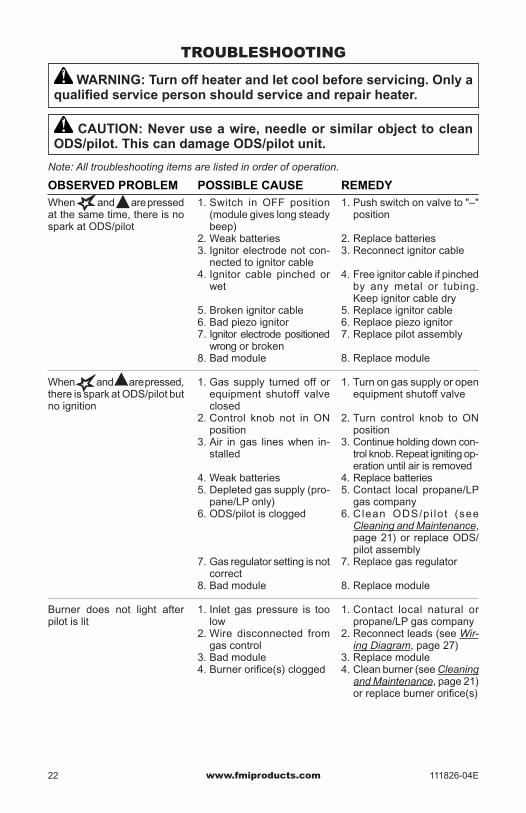
TROUBLESHOOTING
WARNING: Turn off heater and let cool before servicing. Only a qualified service person should service and repair heater.
CAUTION: Never use a wire, needle or similar object to clean ODS/pilot. This can damage ODS/pilot unit.
Note: All troubleshooting items are listed in order of operation.
POSSIBLE CAUSE1. Switch in OFF position
(module gives long steady beep)
2. Weak batteries3. Ignitor electrode not con-
nected to ignitor cable4. Ignitor cable pinched or
wet
5. Broken ignitor cable6. Bad piezo ignitor7. Ignitor electrode positioned
wrong or broken8. Bad module
1. Gas supply turned off or equipment shutoff valve closed
2. Control knob not in ON position
3. Air in gas lines when in-stalled
4. Weak batteries5. Depleted gas supply (pro-
pane/LP only)6. ODS/pilot is clogged
7. Gas regulator setting is not correct
8. Bad module
1. Inlet gas pressure is too low
2. Wire disconnected from gas control
3. Bad module4. Burner orifice(s) clogged
OBSERVED PROBLEMWhen and are pressed at the same time, there is no spark at ODS/pilot
When and are pressed, there is spark at ODS/pilot but no ignition
Burner does not light after pilot is lit
REMEDY1. Push switch on valve to "–"
position
2. Replace batteries3. Reconnect ignitor cable
4. Free ignitor cable if pinched by any metal or tubing. Keep ignitor cable dry
5. Replace ignitor cable6. Replace piezo ignitor 7. Replace pilot assembly
8. Replace module
1. Turn on gas supply or open equipment shutoff valve
2. Turn control knob to ON position
3. Continue holding down con-trol knob. Repeat igniting op-eration until air is removed
4. Replace batteries5. Contact local propane/LP
gas company6. Clean ODS/pi lot (see
Cleaning and Maintenance, page 21) or replace ODS/pilot assembly
7. Replace gas regulator
8. Replace module
1. Contact local natural or propane/LP gas company
2. Reconnect leads (see Wir-ing Diagram, page 27)
3. Replace module4. Clean burner (see Cleaning
and Maintenance, page 21) or replace burner orifice(s)

www.fmiproducts.com111826-04E 23
TROUBLESHOOTINGContinued
OBSERVED PROBLEM
Delayed ignition burner
Burner backfiring during combustion
Orange flame in burner during burner combustion
Slight smoke or odor during initial operation (first hour)
Appliance produces a whis-tling noise when burner is lit
White powder residue forming within burner box or on adja-cent walls or furniture
Remote does not function
Appliance produces a clicking/ticking noise just after burner is lit or shut off
Batteries drain quickly and must be replaced often
REMEDY
1. Contact local natural or propane/LP gas company
2. Clean burner (see Cleaning and Maintenance, page 21) or replace burner orifice
1. Clean burner (see Cleaning and Maintenance, page 21) or replace burner orifice
2. Replace damaged burner3. Replace gas regulator
1. Check burner for dirt and debris. If found, clean burner (see Cleaning and Maintenance, page 21)
2. Replace gas control
1. Problem will stop after a few hours of operation
1. Operate burner until air is removed from line. Have gas line checked by local natural or propane/LP gas company
2. Clean burner (see Cleaning and Maintenance, page 21) or replace burner orifice
1. Turn appliance off when using furniture polish, wax, carpet cleaners or similar products
1. Replace batteries in remote control
2. Replace module
1. This is normal with most appliances. If noise is ex-cessive, contact qualified service person
1. Operate unit with screens closed and glass doors fully open
2. Replace receiver module
POSSIBLE CAUSE
1. Manifold pressure is too low
2. Burner orifice(s) clogged
1. Burner orifice is clogged or damaged
2. Damaged burner3. Gas regulator defective
1. Not enough air
2. Gas regulator defective
1. Residues from manufac-turing processes and logs curing
1. Air in gas line
2. Dirty or partially clogged burner orifice(s)
1. When heated, vapors from furniture polish, wax, car-pet cleaners, etc. may turn into white powder residue
1. Battery is not installed. Battery power is low
2. Bad module
1. Metal expanding while heating or contracting while cooling
1. Operating unit with glass doors closed
2. Bad receiver module

www.fmiproducts.com 111826-04E24
TROUBLESHOOTING Continued
WARNING: If you smell gas• Shut off gas supply.• Do not try to light any appliance.• Do not touch any electrical switch; do not use any phone in your
building.• Immediately call your gas supplier from a neighbor’s phone. Fol-
low the gas supplier’s instructions.• If you cannot reach your gas supplier, call the fire department.
IMPORTANT: Operating heater where impurities in air exist may create odors. Cleaning sup-plies, paint, paint remover, cigarette smoke, cements and glues, new carpet or textiles, etc., create fumes. These fumes may mix with combustion air and create odors. These odors will disappear over time.
POSSIBLE CAUSE1. Appliance burning vapors
from paint, hair spray, glues, cleaners, chemicals, new carpet, etc. (See IMPOR-TANT statement above)
2. Low fuel supply (propane/LP only)
3. Gas leak. See Warning statement at top of page
1. Not enough fresh air is available
2. Low line pressure
3. ODS/pi lot is part ia l ly clogged
1. Gas leak. See Warning statement at top of page
2. Control valve defective
1. Foreign matter between control valve and burner
2. Gas leak. See Warning statement at top of page
1. Bat tery near ly down. (When signal appears the first time approximately 10 ignitions left)
1. Cable is not connected, ON/OFF switch is in OFF posi-tion
1. Ignition not successful, possible air in supply line
REMEDY1. Open window to ventilate
room. Stop using odor caus-ing products while appliance is running
2. Refill supply tank (propane/LP only)
3. Locate and correct all leaks (see Checking Gas Con-nections, page 14)
1. Open window and/or door for ventilation
2. Contact local natural or propane/LP gas company
3. Clean ODS/pi lot (see Cleaning and Maintenance, page 21)
1. Locate and correct all leaks (see Checking Gas Con-nections, page 14)
2. Replace control valve
1. Take apart gas tubing and remove foreign matter
2. Locate and correct all leaks (see Checking Gas Con-nections, page 14)
1. Replace battery
1. Connect cables
1. Switch to ON. Repeat procedure
OBSERVED PROBLEMAppliance produces un-wanted odors
Appliance shuts off in use (ODS operates)
Gas odor even when control knob is in OFF position
Gas odor during combustion
Long signals (0.8 second tone, 0.2 second break) dur-ing ignition
5 second continuous tone
5 short signals (8.2 second tone, 0.2 second break)
IDENTIFYING ERROR SIGNALS FROM RECEIvER

www.fmiproducts.com111826-04E 25
SPECIFICATIONS
SERVICE HINTSWhen Gas Pressure Is Too Low• pilot will not stay lit• burners will have delayed ignition• heater will not produce specified heat• (for propane/LP units) propane/LP gas
supply may be lowYou may feel your gas pressure is too low. If so, contact your local propane/LP or natural gas supplier.
Models VF-18N-PJD• Input Rating: 21,000/30,000 Btu/Hr• Fuel: Natural Gas• Ignition: Piezo• Manifold Pressure: 3.5" W.C.• Inlet Gas Pressure (in. of water): Max. - 10.5" W.C, Min. - 5.0 W.C *• Shipping Weight: 32 lbs. * For purpose of input adjustment
Models VF-18P-PJD• Input Rating: 21,000/30,000 Btu/Hr• Fuel: Propane/LP Gas• Ignition: Piezo• Manifold Pressure: 10" W.C.• Inlet Gas Pressure (in. of water): Max.- 14" W.C, Min. - 11" W.C *• Shipping Weight: 32 lbs.* For purpose of input adjustment
Models VF-24N-PJD and VF-30N-PJD• Input Rating: 21,000/39,000 Btu/Hr• Fuel: Natural Gas• Ignition: Piezo• Manifold Pressure: 3.5" W.C.• Inlet Gas Pressure (in. of water): Max. - 10.5" W.C, Min. - 5.0 W.C *• Shipping Weight: 34 lbs. * For purpose of input adjustment
Models VF-24P-PJD and VF-30P-PJD• Input Rating: 21,000/39,000 Btu/Hr• Fuel: Propane/LP Gas• Ignition: Piezo• Manifold Pressure: 10" W.C.• Inlet Gas Pressure (in. of water): Max.- 14" W.C, Min. - 11" W.C *• Shipping Weight: 34 lbs.* For purpose of input adjustment
TECHNICAL SERVICEYou may have further questions about instal-lation, operation, or troubleshooting. If so, contact FMI PRODUCTS, LLC at 1-866-328-4537. When calling please have your model and serial numbers of your heater ready.You can also visit our web site at www.fmiproducts.com.
www.fmiproducts.com 111826-04E26
REPLACEMENT PARTS
ACCESSORIES
Note: Use only original replacement parts. This will protect your warranty coverage for parts replaced under warranty.
PARTS UNDER WARRANTYContact authorized dealers of this product. If they can’t supply original replacement part(s), call FMI PRODUCTS, LLC at 1-866-328-4537.
When calling, have ready:• your name• your address• model and serial numbers of your heater• how heater was malfunctioning• purchase dateUsually, we will ask you to return the part to the factory.
Purchase these accessories from your local dealer. If they can not supply these accessories call FMI PRODUCTS, LLC at 1-866-328-4537 for information. You can also write to the ad-dress listed on the back page of this manual.
FIREPLACE HOODBlack - GA6050Antique Brass - GA6053For all models. Helps deflect heat away from mantel or wall above fireplace. Fits openings 28" to 48" wide.
DAMPER CLAMP - GA6080For Remote-Ready and Variable Manually-Controlled Models. Permanently opens chimney flue damper for vented operation.
LAVA ROCK - GA6060For all models. Order when additional rock is desired.
FLOOR MEDIA KIT- VTA-LS5-1For all models. Order when additional logs is desired.
FLOOR MEDIA KIT- VTA-LS5-2For all models. Order when additional logs are desired.
www.fmiproducts.com111826-04E 27
SPARK
SPARK
Pilot
4 AA Batteries
ON/OFFSwitch
ThermocurrentInterrupter Block
SW
SW
TC
TC
Battery Compartment
MAGRMOSW
PA
NE
L
Receiver
AntennaIgnition Cable
Thermocouple
ThermocurrentInterrupter Block
Combination Control
ON/OFF Switch (Optional)
OFFON
8 Wire Connecting Cable
Thermocurrent Cable #2or ON/OFF SwitchSoldered Cable
ThermocurrentCable #1
Motor Knob
MAN Knob
WIRING DIAGRAM

www.fmiproducts.com 111826-04E28
PARTS
MODELS VF-18N-PJD AND VF-18P-PJD
1
2
24
24
24
24
24
24
24
24
78
9
101112
11 13
14
15
16
17
18
3 6 4
19
20
21
2223
5

www.fmiproducts.com111826-04E 29
kEY NO.
PART NUMBER
DESCRIPTION QTY.VF-18N-PJD VF-18P-PJD1 ** ** Chassis 12 112791-01 112791-01 Grate 13 116672-01 116672-02 PJD Remote Valve 14 116673-01 116673-01 PJD Module, Maxitrol 1
5 116673-02 116673-02 Hand-Held Remote Control 16 112814-06 112814-06 Valve Bracket 17 116328-01 116328-01 Rear Burner 18 116559-01 116559-01 Air Shutter 19 114365-04 114365-06 Orifice, Front 110 114365-05 114365-06 Orifice, Rear 111 111824-01 111824-01 3/8" Nut/Sleeve 212 111817-05 111817-05 Rear Flextube 113 116336-01 116336-01 Rear Log Plate 114 112812-06 112812-06 Left Burner Bracket 115 111804-08 111804-08 Front Burner 116 112812-05 112812-05 Right Burner Bracket 117 116242-01 116242-01 Log Support Bracket 118 111817-06 111817-06 Front Flextube 119 104285-01 104286-01 ODS Pilot 120 098249-01 098249-01 ODS Nut 221 116329-02 116329-02 Front Log Bracket 122 111817-03 111817-03 3/16" Flextube 123 111828-01 111828-01 3/16" Nut/Sleeve 124 M11084-26 M11084-26 Screw, #10-24 x 0.375 17
PARTS AVAILABLE NOT SHOWN
116680-01 116680-01 Front Log Kit 1116680-07 116680-07 Ember Pod Kit 1116680-08 116680-08 Back Log Kit 1100563-01 100563-01 Warning Plate 1112796-01 112796-01 Lighting Instructions Plate 1100639-05 100693-05 Caution Decal 1112363-01 112363-01 Log Ember Kit #1 112364-01 112364-01 Log Ember Kit #2 1112799-01 112799-01 Ember Flakes Kit 1111288-02 111288-02 Gas Line Flex with Shut Off 1
** Not a field replaceable part.
PARTSThis list contains replaceable parts used in your heater. When ordering parts, follow instruc-tions listed under Replacement Parts on page 26 of this manual.

www.fmiproducts.com 111826-04E30
12
3 64
25
25
25
25
25
25
7
8
9
10
11
11
12 13
1415
16
17
18
19
20
21
22
2324
5
PARTSMODELS VF-24N-PJD AND VF-24P-PJD

www.fmiproducts.com111826-04E 31
** Not a field replaceable part.
kEY NO.
PART NUMBER
DESCRIPTION QTY.VF-24N-PJD VF-24P-PJD1 ** ** Chassis 12 111811-01 111811-01 Grate 13 116672-01 116672-02 PJD Remote Valve 14 116673-01 116673-01 PJD Module, Maxitrol 1
5 116673-02 116673-02 Hand-Held Remote Control 16 112814-06 112814-06 Valve Bracket 17 112828-01 112828-01 Rear Burner 18 112829-01 112829-01 Air Shutter 19 114365-01 114365-03 Orifice, Front 110 114365-02 114365-03 Orifice, Rear 111 111824-01 111824-01 3/8" Nut/Sleeve 212 111817-05 111817-05 Rear Flextube 113 112812-02 112812-02 Rear Log Plate 114 112812-06 112812-06 Left Burner Bracket 115 111804-05 111804-05 Front Burner 116 112812-05 112812-05 Right Burner Bracket 117 116331-01 116331-01 Right Ember Plate 118 111817-06 111817-06 Front Flextube 119 116680-04 116680-05 Pilot Bracket Kit 120 104285-01 104286-01 ODS Pilot 121 116337-01 — NG Pilot Shield 122 116329-01 116329-01 Front Log Bracket 123 111817-03 111817-03 3/16" Flextube 124 111828-01 111828-01 3/16" Nut/Sleeve 125 M11084-26 M11084-26 Screw, #10-24 x 0.375 18
PARTS AVAILABLE NOT SHOWN
116680-02 116680-02 Front Log Kit 1116680-04 116680-05 Left Ember Pod Kit 1116880-06 116680-06 Right Ember Pod Kit 1116680-09 116680-09 Back Log Kit 1100563-01 100563-01 Warning Plate 1112796-01 112796-01 Lighting Instructions Plate 1100639-05 100693-05 Caution Decal 1112363-01 112363-01 Log Ember Kit #1 112364-01 112364-01 Log Ember Kit #2 1112799-01 112799-01 Ember Flakes Kit 1111288-02 111288-02 Gas Line Flex with Shut Off 1
PARTSThis list contains replaceable parts used in your heater. When ordering parts, follow instruc-tions listed under Replacement Parts on page 26 of this manual.
www.fmiproducts.com 111826-04E32
1
3
18
5
6 4
24
2
24
24
24
7
9
1110
11
1224
1917
24
13
8
14
15 16
2223 20 25
21
PARTSMODELS VF-30N-PJD AND VF-30P-PJD

www.fmiproducts.com111826-04E 33
** Not a field replaceable part.
kEY NO.
PART NUMBER
DESCRIPTION QTY.VF-30N-PJD VF-30P-PJD1 ** ** Chassis 12 116403-01 116403-01 Grate 13 116672-01 116672-02 PJD Remote Valve 14 116673-01 116673-01 PJD Module, Maxitrol 1
5 116673-02 116673-02 Hand-Held Remote Control 16 112814-06 112814-06 Valve Bracket 17 117118-01 117118-01 Rear Burner 18 116659-02 116659-01 Air Shutter 19 114365-01 114365-06 Orifice, Front 110 114365-02 114365-04 Orifice, Rear 111 111824-01 111824-01 3/8" Nut/Sleeve 212 111817-01 111817-01 Rear Flextube 113 117686-01 117686-01 Rear Log Plate 114 112812-06 112812-06 Left Burner Bracket 115 111804-05 111804-05 Front Burner 116 112812-05 112812-05 Right Burner Bracket 117 117416-02 117416-02 Right Ember Plate 118 111817-06 111817-06 Front Flextube 119 117416-01 117416-01 Left Ember Plate 120 104285-01 104286-01 ODS Pilot 121 116329-03 116329-03 Front Log Bracket 122 111817-03 111817-03 3/16" Flextube 123 111828-01 111828-01 3/16" Nut/Sleeve 124 M11084-26 M11084-26 Screw, #10-24 x 0.375 2125 098249-01 098249-01 ODS Nut 2
PARTS AVAILABLE NOT SHOWN
116680-03 116680-03 Front Log Kit 1116680-10 116680-10 Back Log Kit 1116680-11 116680-11 Rear Log and Plate Kit 1116680-12 116680-12 Left Ember Pod Kit 1116880-13 116680-13 Right Ember Pod Kit 1100563-01 100563-01 Warning Plate 1112796-01 112796-01 Lighting Instructions Plate 1100639-05 100693-05 Caution Decal 1112363-01 112363-01 Log Ember Kit #1 112364-01 112364-01 Log Ember Kit #2 1112799-01 112799-01 Ember Flakes Kit 1111288-02 111288-02 Gas Line Flex with Shut Off 1
PARTSThis list contains replaceable parts used in your heater. When ordering parts, follow instruc-tions listed under Replacement Parts on page 26 of this manual.

www.fmiproducts.com 111826-04E34
_______________________________________________________________________________________________________________________________________________________________________________________________________________________________________________________________________________________________________________________________________________________________________________________________________________________________________________________________________________________________________________________________________________________________________________________________________________________________________________________________________________________________________________________________________________________________________________________________________________________________________________________________________________________________________________________________________________________________________________________________________________________________________________________________________________________________________________________________________________________________________________________________________________________________________________________________________________________________________________________________________________________________________________________________________________________________________________________________________________________________________________________________________________________________________________________________________________________________________________________________________________________________________________________________________________________________________________________________________________________________________________________________________________________________________________________________________________________________
NOTES

www.fmiproducts.com111826-04E 35
_______________________________________________________________________________________________________________________________________________________________________________________________________________________________________________________________________________________________________________________________________________________________________________________________________________________________________________________________________________________________________________________________________________________________________________________________________________________________________________________________________________________________________________________________________________________________________________________________________________________________________________________________________________________________________________________________________________________________________________________________________________________________________________________________________________________________________________________________________________________________________________________________________________________________________________________________________________________________________________________________________________________________________________________________________________________________________________________________________________________________________________________________________________________________________________________________________________________________________________________________________________________________________________________________________________________________________________________________________________________________________________________________________________________________________________________________________________________________
NOTES

111826-04Rev. E09/09
WARRANTykEEP THIS WARRANTy
FMI PRODUCTS, LLC LIMITED WARRANTIESNew Products
Standard Warranty: FMI PRODUCTS, LLC warrants this new product and any parts thereof to be free from defects in material and workmanship for a period of four (4) year from the date of first purchase from an authorized dealer provided the product has been installed, maintained and operated in accordance with FMI PRODUCTS, LLC’s warnings and instructions.
For products purchased for commercial, industrial or rental usage, this warranty is limited to 90 days from the date of first purchase.
Factory Reconditioned ProductsLimited Warranty: FMI PRODUCTS, LLC warrants factory reconditioned products and any parts thereof to be free from defects in material and workmanship for 30 days from the date of first purchase from an authorized dealer provided the product has been installed, maintained and operated in accordance with FMI PRODUCTS, LLC’s warnings and instructions.
Terms Common to All WarrantiesThe following terms apply to all of the above warranties:
Always specify model number and serial number when contacting the manufacturer. To make a claim under this warranty the bill of sale or other proof of purchase must be presented.
This warranty is extended only to the original retail purchaser when purchased from an authorized dealer, and only when installed by a qualified installer in accordance with all local codes and instructions furnished with this product.
This warranty covers the cost of part(s) required to restore this product to proper operating condition and an allowance for labor when provided by a FMI PRODUCTS, LLC Authorized Service Center or a provider approved by FMI PRODUCTS, LLC. Warranty parts must be obtained through authorized dealers of this product and/or FMI PRODUCTS, LLC who will provide original factory replacement parts. Failure to use original factory replacement parts voids this warranty.
Travel, handling, transportation, diagnostic, material, labor and incidental costs associated with warranty repairs, unless expressly covered by this warranty, are not reimbursable under this warranty and are the responsibility of the owner.
Excluded from this warranty are products or parts that fail or become damaged due to misuse, accidents, improper installation, lack of proper maintenance, tampering, or alteration(s).
This is FMI PRODUCTS, LLC’s exclusive warranty, and to the full extent allowed by law; this express war-ranty excludes any and all other warranties, express or implied, written or verbal and limits the duration of any and all implied warranties, including warranties of merchantability and fitness for a particular purpose to four (4) year on new products and 30 days on factory reconditioned products from the date of first purchase. FMI PRODUCTS, LLC makes no other warranties regarding this product.
FMI PRODUCTS, LLC’s liability is limited to the purchase price of the product, and FMI PRODUCTS, LLC shall not be liable for any other damages whatsoever under any circumstances including indirect, incidental, or consequential damages.
Some states do not allow limitations on how long an implied warranty lasts or the exclusion or limitation of incidental or consequential damages, so the above limitation or exclusion may not apply to you.
This warranty gives you specific legal rights, and you may also have other rights which vary from state to state.
For information about this warranty contact:
Model (located on product or identification tag) _____________________________
Serial No. (located on product or identification tag) __________________________
Date Purchased __________________________
Keep receipt for warranty verification.
2701 S. Harbor Blvd.Santa Ana, CA 92704
1-866-328-4537www.fmiproducts.com