Unrestricted © Siemens AG 2015 Femap Symposium Series 2015 Working with Femap Free bodies and...
51
Unrestricted © Siemens AG 2015 Femap Symposium Series 2015 Working with Femap Free bodies and Global / Local Modeling
-
Upload
ashley-mcbride -
Category
Documents
-
view
220 -
download
1
Transcript of Unrestricted © Siemens AG 2015 Femap Symposium Series 2015 Working with Femap Free bodies and...

Unrestricted © Siemens AG 2015
Femap Symposium Series 2015
Working with Femap Free bodies and Global / Local Modeling

Page 2 Siemens PLM Software
Siemens PLM UK SymposiumFemap Track Agenda
11:00: Femap – introduction and what’s new
11:50: Working with Femap – free bodies and global / local modeling
13:30: Femap industry customer case studies:Aerospace & marine
Customer presentationLongitude Consulting Engineers (London Offshore Consulting)
Your presenters today:
Nick Rakkar UK Channel Sales Manager, Siemens PLM SoftwareAl Robertson Product Marketing Manager, Siemens PLM SoftwareJoe Brackin Senior Software Engineer, Siemens PLM SoftwarePeter Kingsland Naval Architect, Longitude Consulting Engineers

Page 3 Siemens PLM Software
Siemens PLM UK SymposiumFemap Track Agenda
15:40: Event wrap up We will be available for questions and discussion after the event
• Femap futures and roadmap• Femap technical queries• How can Femap help in your business• Who can you talk to regarding software solution testing
Nick Rakkar – UK Channel Sales Manager
07837 553 633

Page 4 Siemens PLM Software
FEMAP Freebody Deep Dive
Topics
• What is a Freebody?• Recovering Grid Point Forces in NASTRAN• Understanding Grid Point Force Output• Freebodies in FEMAP• Using the FEMAP Freebody Toolbox• FEMAP Freebody Options• Global / Local Modelling with Freebodies• Additional Topics

Page 5 Siemens PLM Software
What is a Freebody?
Freebody Displays provide an insight into the internal forces and moments of the FEM
• In FEMAP, Freebody display can be used to display a balanced set of loads on a portion of the structureor calculate the load across an interface
• Freebody displays are commonly used when modeling practices dictate that the resulting FE mesh is a “coarse-grid” mesh but is suitable as an “internal loads” model
• Commonly modeled structures are often too complicated to model in sufficient detail to obtain directly useable stresses
• Allows for forces / moments to be extracted for detail stress analysis
• Freebody displays are heavily used (but not limited to) in the aerospace industry
Page 6 Siemens PLM Software
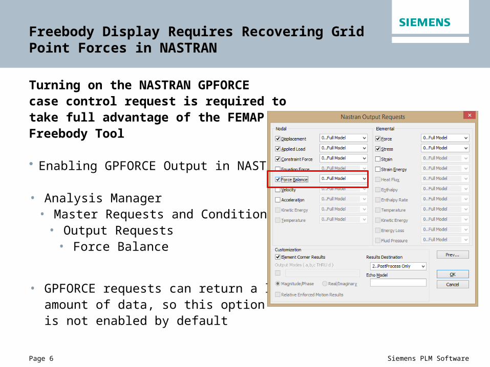
Freebody Display Requires Recovering Grid Point Forces in NASTRAN
Turning on the NASTRAN GPFORCE case control request is required to take full advantage of the FEMAP Freebody Tool
• Enabling GPFORCE Output in NASTRAN Case Control
• Analysis Manager• Master Requests and Conditions
• Output Requests• Force Balance
• GPFORCE requests can return a largeamount of data, so this optionis not enabled by default

Page 7 Siemens PLM Software
Freebody Display Requires Recovering Grid Point Forces in NASTRAN
• FEMAP can work with a reduced set of data including applied load (OLOAD), constraint force (SPCFORCE), and constraint equation (MPCFORCE)
• This is generally not recommended unless only a generic freebody display of the entire structure is all that’s required.
• Care should be taken whennot requesting GPFORCE data forthe entire model.

Page 8 Siemens PLM Software
Understanding Grid Point Force Output
NASTRAN F06 Output
• When the results destination is set to “Print Only” or “Print and PostProcess” GPFORCE data can be viewed in the F06 file
• Note that it is still recommended to read GPFORCE data into FEMAP from the OP2 file, not the F06 file
• Search for “G R I D P O I N T F O R C E B A L A N C E”
G R I D P O I N T F O R C E B A L A N C E
POINT-ID ELEMENT-ID SOURCE T1 T2 T3 R1 R2 R3 1 F-OF-SPC 4.169596E-02 1.031393E+00 -5.078434E+01 0.0 0.0 0.0 1 267 QUAD4 1.213303E-01 5.287078E+00 -1.944031E+01 2.078351E-03 5.017486E-01 4.834255E-04 1 268 QUAD4 -1.630262E-01 -6.318471E+00 7.022465E+01 -2.078351E-03 -5.017486E-01 -4.834255E-04 1 *TOTALS* 9.436896E-16 -6.306067E-14 2.557954E-13 1.934217E-16 0.0 -2.333203E-160 2 267 QUAD4 -7.904667E-01 -1.515594E+02 3.756228E+02 1.975718E-01 5.075642E-01 1.493221E-02 2 268 QUAD4 -3.752280E-01 -1.348000E+02 -4.464662E+02 1.780457E-01 -5.262242E-01 2.671471E-02 2 269 QUAD4 5.058178E-01 1.277458E+02 2.504629E+00 -1.799477E-01 -1.129834E-01 -4.392642E-02 2 270 QUAD4 6.598768E-01 1.586136E+02 6.833877E+01 -1.956698E-01 1.316434E-01 2.279495E-03 2 *TOTALS* -1.798561E-14 -1.136868E-12 7.389644E-13 6.383782E-16 1.493250E-14 5.551115E-170 3 269 QUAD4 -2.833224E-01 -7.450614E+01 3.083269E+02 1.501767E-01 -1.241496E-01 2.011796E-02 3 270 QUAD4 -2.021358E-01 -4.297056E+01 -3.489907E+02 1.569770E-01 1.129076E-01 4.146868E-02 3 271 QUAD4 1.617432E-01 5.205509E+01 -2.303685E+01 -1.572558E-01 -2.788103E-01 -1.574009E-02 3 272 QUAD4 3.237150E-01 6.542161E+01 6.370063E+01 -1.498980E-01 2.900524E-01 -4.584655E-02 3 *TOTALS* 1.049161E-14 8.540724E-12 -2.700062E-13 1.665335E-16 -2.886580E-15 8.326673E-17

Page 9 Siemens PLM Software
Understanding Grid Point Force Output
NASTRAN F06 Output
• GPFORCE results are listed per grid and include Fxyz (T1, T2, T3) and Mxyz (R1, R2, R3)
• Results are separated into 4 different categories, plus a summation• Elemental (discrete; per connecting flexible element)• Applied Load(total forces / moments applied on node; single quantity per
node)• F-of-SPC (SPC forces on node; single quantity per node)• F-of-MPC (MPC forces on node, including both constraint equations and
RBE contributions; single quantity per node)• *TOTALS* (total summation of all contributions; single quantity per node)
• For the majority of cases, this value should be near zero, indicating equilibrium at the node
Page 10 Siemens PLM Software
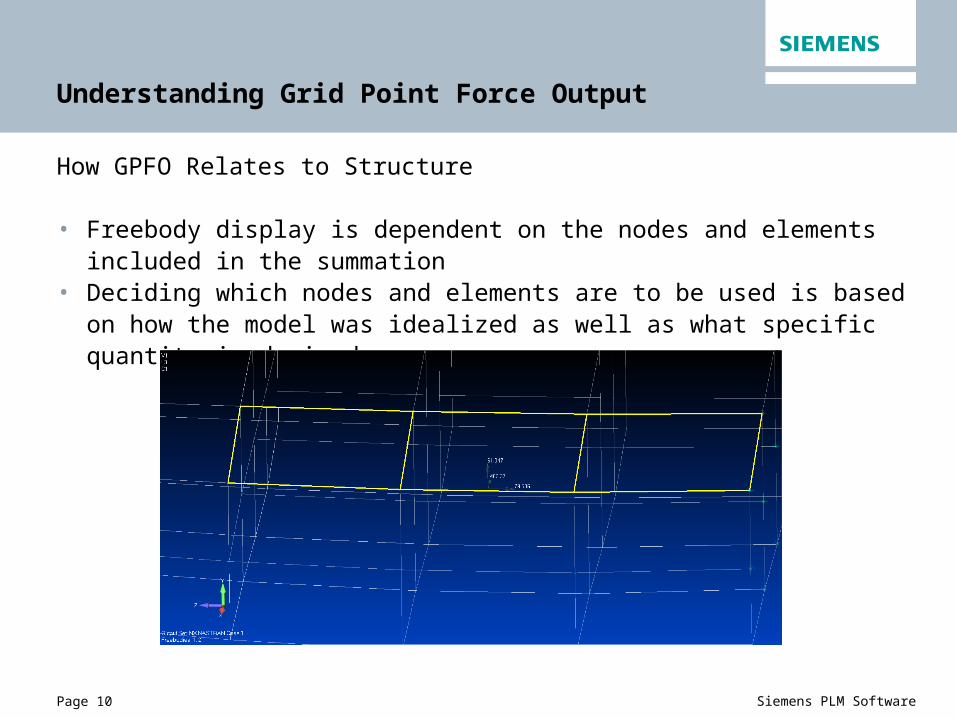
Understanding Grid Point Force Output
How GPFO Relates to Structure
• Freebody display is dependent on the nodes and elements included in the summation
• Deciding which nodes and elements are to be used is based on how the model was idealized as well as what specific quantity is desired

Page 11 Siemens PLM Software
Freebody Display in FEMAP
Freebodies in FEMAP exist as creatable objects, like nodes, elements, etc.
• They persist in the database• This is a huge benefit for recreating freebody displays in the future• Can help reduce analysis errors and rework
• Any number of freebodies can be displayed simultaneously• Many tools exist to automate freebody-related tasks, such as creating loads
and substructure modeling

Page 12 Siemens PLM Software
Freebody Display in FEMAP
FEMAP Freebody Types – There are 3 types of freebody displays in FEMAP
• Freebody – user selects the elements, FEMAP automatically selects related nodes. Intended to display a balanced set of loads on a discrete piece of structure
Page 13 Siemens PLM Software
Freebody Display in FEMAP
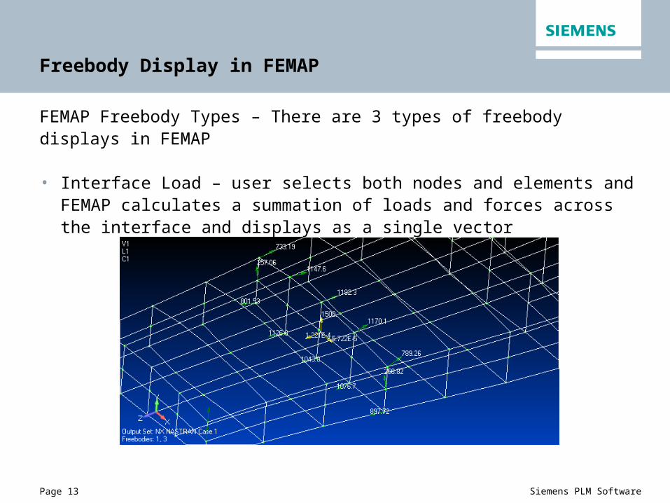
FEMAP Freebody Types – There are 3 types of freebody displays in FEMAP
• Interface Load – user selects both nodes and elements and FEMAP calculates a summation of loads and forces across the interface and displays as a single vector

Page 14 Siemens PLM Software
Freebody Display in FEMAP
FEMAP Freebody Types – There are 3 types of freebody displays in FEMAP
• Section Cut – similar to interface load, a summed load across an interface is calculated and displayed, however node and element selection is automated by FEMAP. The user selects a “cutting plane”. The cutting plane can then be dynamically located within the model using different methods.

Page 15 Siemens PLM Software
Freebody Display in FEMAP
Freebody Load Contributions
• Freebody load contributions in FEMAP are split into six categories• Applied – All applied loads• Reaction – SPC forces(Constraint forces)• MultiPoint Reaction –
MPC(MultiPoint Constraint forces)• Peripheral Elements – include elements
surrounding the selected elements• Freebody Elements – include elements
selected by the user or by FEMAP• Nodal Summation – nodal summation values
from the solver, not FEMAP calculated values• Default contributions are Applied, Reaction, MultiPoint Reaction and
Peripheral elements• This provides forces and moments acting on the selected structure

Page 16 Siemens PLM Software
Freebody Display in FEMAP
Freebody Result Vectors – As previously mentioned, the NASTRAN GPFORCE request is recommended to fully take advantage of the freebody tool, however the result quantities may be obtained from several different quantities
The italicized rows above represent default output requests in FEMAP and are sufficient for displaying a balanced freebody on the entire structure, but not for display of internal load distribution.
Primary Secondary
Applied GPFORCE OLOAD
SPC GPFORCE SPCFORCE
MPC GPFORCE MPCFORCE
Elemental GPFORCE None
Nodal Summation GPFORCE None
Page 17 Siemens PLM Software
Using the FEMAP Freebody Toolbox
Accessing the Freebody Toolbox
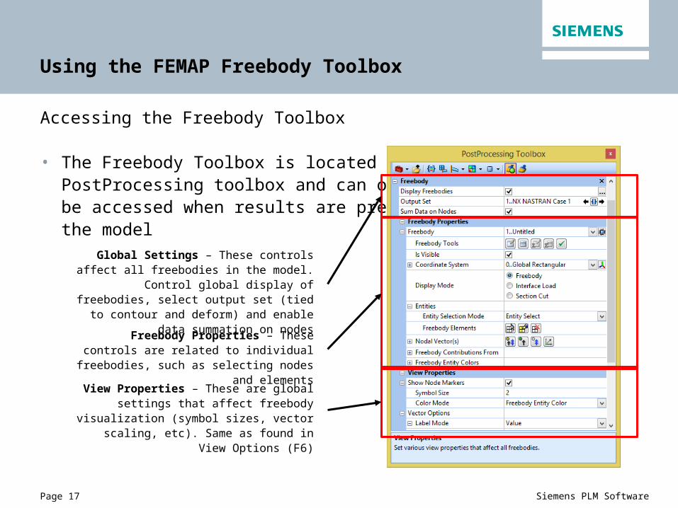
• The Freebody Toolbox is located in the PostProcessing toolbox and can only be accessed when results are present in the model
Global Settings – These controls affect all freebodies in the model. Control global display of freebodies, select output set (tied to contour
and deform) and enable data summation on nodes
Freebody Properties – These controls are related to individual freebodies, such as
selecting nodes and elements
View Properties – These are global settings that affect freebody visualization (symbol sizes,
vector scaling, etc). Same as found in View Options (F6)

Page 18 Siemens PLM Software
Using the FEMAP Freebody Toolbox
Creating a New Freebody
• In the Freebody Toolbox, new Freebody Displays are created within the Freebody Manager
• The New Freebody dialog allows for setup of basic settings, such as freebody type, vector display, and contribution selection
• Any of the settings applied in the New Freebody dialog can be changed at any time within the toolbox

Page 19 Siemens PLM Software
Using the FEMAP Freebody Toolbox
Accessing Different Freebody Displays
• Multiple Freebody Displays can be viewed at any time however, only a single freebody can be active at any time within the toolbox
• Use the drop-down menu to change the active freebody and then modify settings
• Visibility of individual freebody displays can becontrolled with the “Is Visible” checkbox aswell as with the Visibility Quick View Dialog
Page 20 Siemens PLM Software
Using the FEMAP Freebody Toolbox
Freebody Vector Types
• Depending on the freebody type, there can be nodal vectors and a single total summation vector
• Nodal Vectors • Displays the summation at each node, based on the selected freebody
contributions• Available for all freebody types
• Total Summation Vector • Displays the total summation across all nodes at a pre-defined position.
The selected position does not affect summed force calculations, but will affect summed moment calculations (moment arms are different).
• Available for Interface Load and Section Cut freebodies only.• Both force and moment vectors are available and can be individually toggled• Vectors can be displayed as either components or resultant vectors• Individual components can be toggled on and off

Page 21 Siemens PLM Software
Using the FEMAP Freebody Toolbox
Freebody Vector Visualization
Visibility Quick Toggle Buttons• All On / All Off• Forces On/Off• Moments On/Off• Toggle between resultant/component• Select summation location (interface load
and section cut only)

Page 22 Siemens PLM Software
Using the FEMAP Freebody Toolbox
Freebody Vector Visualization
Detail Options• Additional detailed options for visualization
can be found by expanding the Total Summation Vector and Nodal Vector(s) nodes
• Select components displayed (Fx, Fy, Fz), (Mx, My, Mz)
• Select components included in calculation (interface load and section cut only)

Page 23 Siemens PLM Software
Using the FEMAP Freebody Toolbox
Freebody Coordinate Systems
• The selected freebody coordinate system controls the coordinate system for both nodal vectors and the total summation vector (if applicable) for the selected freebody
• Nodal vectors may optionally be displayed in the nodal output coordinate system
• If no nodal output system was specified on the node, the default coordinate system used is the global rectangular system

Page 24 Siemens PLM Software
Using the FEMAP Freebody Toolbox
Freebody Mode
• When using “Freebody Mode”, the user selects elements and FEMAP will automatically select all related nodes
• This mode is designed to display a balanced set of loads on a selected set of elements
• Entities may be selected manually (default) or by a group select
• The default contribution selections will display forces/moments acting on the selected elements
Select Elements
Highlight Selected Elements
Reset Element Selection

Page 25 Siemens PLM Software
Using the FEMAP Freebody Toolbox
Display of balanced set of loads on wingpost model. All elements in the model were selected for this display

Page 26 Siemens PLM Software
Using the FEMAP Freebody Toolbox
Interface Load Mode
• Interface load freebodies display nodal vectors for the selected nodes as well as a total summation vector at a selected location
• Unlike freebody mode, interface load mode is not likely to be in equilibrium
• In addition to element selection, nodes must be user selected– FEMAP does not infer them based on the selected elements
• When selecting entities by group, both the nodes and elements of interest must exist in the group

Page 27 Siemens PLM Software
Using the FEMAP Freebody Toolbox
Interface Load Mode – Selecting Nodes
Select Nodes
Highlight Selected Nodes
Reset Node Selection
Locate Summation Vector at Node Centroid Select Free Edge Nodes
Only those elements connected to the selected nodes will be used in calculations

Page 28 Siemens PLM Software
Using the FEMAP Freebody Toolbox
Interface Load Mode – Selecting Components in Summation
• Individual force and moment contributions that are included in the total summation vector calculation toggled on and off
• By default, all force and all moment vectors are included in the calculation
• Changes made here will affect the totalsummation calculation
• Turning on and off certain contributions is dependent on how the model was idealized ; it is up to the analyst to understand how the FE model correlates to real-world structure
Page 29 Siemens PLM Software
Using the FEMAP Freebody Toolbox
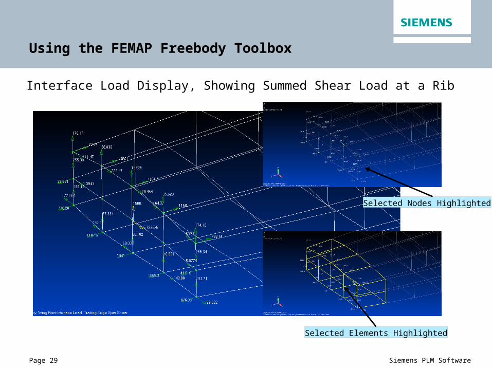
Interface Load Display, Showing Summed Shear Load at a Rib
Selected Elements Highlighted
Selected Nodes Highlighted
Page 30 Siemens PLM Software
Using the FEMAP Freebody Toolbox
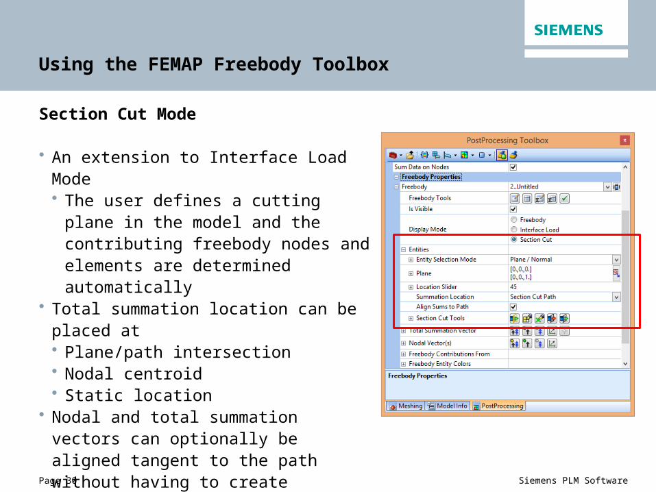
Section Cut Mode
• An extension to Interface Load Mode• The user defines a cutting plane in the
model and the contributing freebody nodes and elements are determined automatically
• Total summation location can be placed at • Plane/path intersection• Nodal centroid• Static location
• Nodal and total summation vectors can optionally be aligned tangent to the path without having to create additional coordinate systems
Page 31 Siemens PLM Software
Using the FEMAP Freebody Toolbox
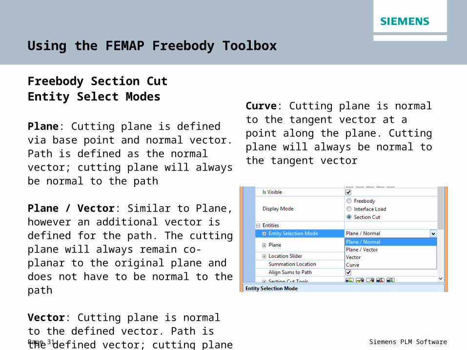
Freebody Section Cut Entity Select Modes
Plane: Cutting plane is defined via base point and normal vector. Path is defined as the normal vector; cutting plane will always be normal to the path
Plane / Vector: Similar to Plane, however an additional vector is defined for the path. The cutting plane will always remain co-planar to the original plane and does not have to be normal to the path
Vector: Cutting plane is normal to the defined vector. Path is the defined vector; cutting plane will always be normal to the path
Curve: Cutting plane is normal to the tangent vector at a point along the plane. Cutting plane will always be normal to the tangent vector

Page 32 Siemens PLM Software
Using the FEMAP Freebody Toolbox
Section cut defined using plane

Page 33 Siemens PLM Software
Using the FEMAP Freebody Toolbox
Section cut defined using curve

Page 34 Siemens PLM Software
Using the FEMAP Freebody Toolbox
Additional Section Cut options
• Slider tool can be used to move the cutting plane along the length of the path interactively within the available entities
• Section cut entities may be limited to a specific group or selected from the entire model, and can be limited to a search distance from the base location of the cutting plane
• The cutting plane can optionally be given a thickness tolerance that will allow for accurate selection of entities that are slightly out-of-plane
• Clipped entities can either be included or excluded from the summation calculations

Page 35 Siemens PLM Software
Using the FEMAP Freebody Toolbox
Cut plane initial position Cut plane moved along the path
Freebody nodes
Freebody elements
Page 36 Siemens PLM Software
Freebody Display Output Options
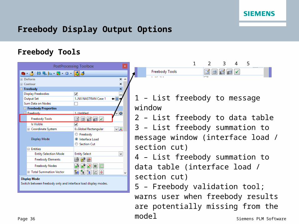
Freebody Tools
1 2 3 4 5
1 – List freebody to message window2 – List freebody to data table3 – List freebody summation to message window (interface load / section cut)4 – List freebody summation to data table (interface load / section cut)5 – Freebody validation tool; warns user when freebody results are potentially missing from the model

Page 37 Siemens PLM Software
Global-Local Modeling with Freebodies
The Create Load from Freebody/Multi-Model tool automates the creation of global-local models
• Used to map freebody loads from a coarse grid model to a fine grid model and automatically create connections with RBE3 elements
• Start with a balanced freebody in a coarse model• FEMAP can automatically locate suitable target nodes in the fine grid FEM and will connect with RBE3 elements
• Once properly constrained, the detail FEM is ready to run with a mapped set of loads
• The detail FEM must exist in the same space as the part in the coarse grid FEM
Page 38 Siemens PLM Software
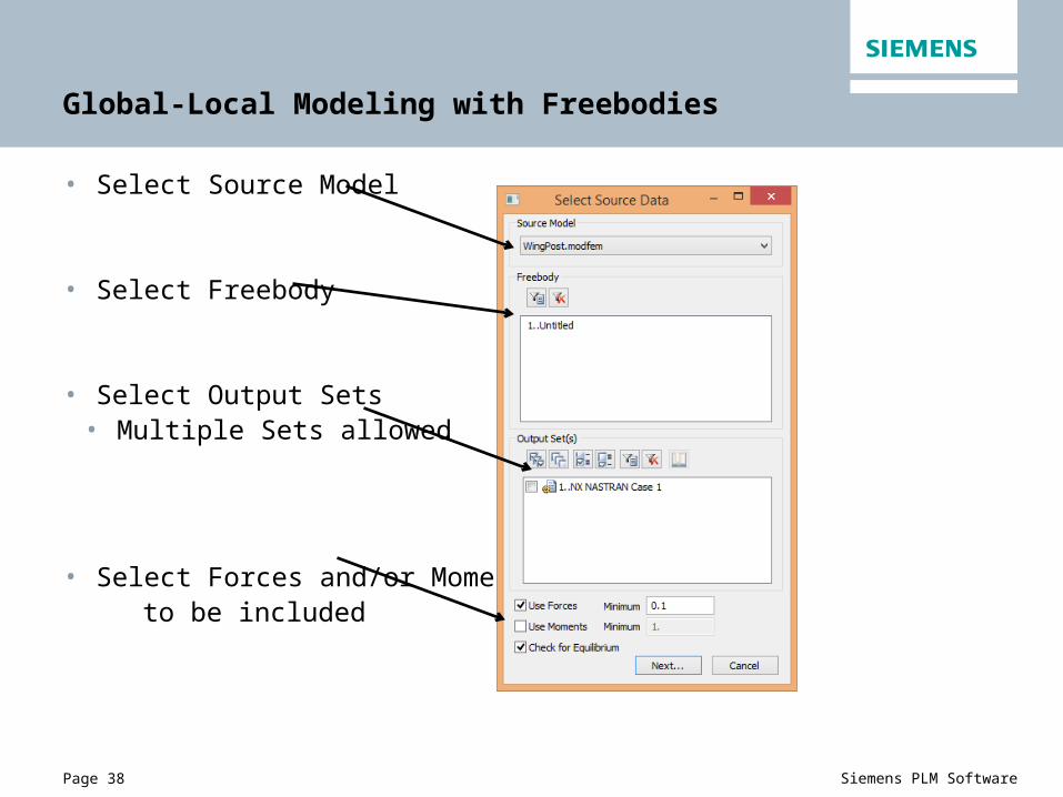
Global-Local Modeling with Freebodies
• Select Source Model
• Select Freebody
• Select Output Sets• Multiple Sets allowed
• Select Forces and/or Moments to be included

Page 39 Siemens PLM Software
Global-Local Modeling with Freebodies
Define Target Model Parameters
Freebody loads can be applied to target nodes based on:
• Existing nodes (IDs must match)• Closest node in space to source
node• Existing nodes to be connected with
RBE3 elements• User can define target nodes or
FEMAP can automatically find• Search distance can be limited• Maximum nodes to map can be
limited

Page 40 Siemens PLM Software
Global-Local Modeling with Freebodies
Source Model Freebody(Global Model)
Target Model with RBE3 Load Distribution

Page 41 Siemens PLM Software
Additional Topics – Freebodies with NX Nastran Glue / Contact
As of NX Nastran v10.1, the GPFORCE output request does not include contributions from glue or contact in the F06 or OP2 datablock
• The result is a nodal imbalance that is the summation of all other contributions• Nodes that are affected by glue or contact will not be in equilibrium• The “TOTALS” quantity is equal and opposite to the existing summation
G R I D P O I N T F O R C E B A L A N C E POINT-ID ELEMENT-ID SOURCE T1 T2 T3 R1 R2 R30 686 821 HEXA -7.854530E-03 5.974986E-02 7.854530E-03 0.0 0.0 0.0 686 822 HEXA -4.059431E-03 4.661321E-02 2.316282E-02 0.0 0.0 0.0 686 827 HEXA 7.568718E-03 -6.126883E-02 -7.568719E-03 0.0 0.0 0.0 686 828 HEXA -2.503399E-02 -9.182400E-02 -3.478359E-03 0.0 0.0 0.0 686 857 HEXA -2.316282E-02 4.661320E-02 4.059429E-03 0.0 0.0 0.0 686 858 HEXA -1.751655E-03 6.132058E-02 1.751656E-03 0.0 0.0 0.0 686 863 HEXA 3.478360E-03 -9.182400E-02 2.503399E-02 0.0 0.0 0.0 686 864 HEXA 5.081535E-02 3.061997E-02 -5.081535E-02 0.0 0.0 0.0 686 *TOTALS* -1.318390E-16 5.620504E-16 -4.440892E-16 0.0 0.0 0.00 10000 468 HEXA 2.385245E-17 5.842150E-02 3.122502E-17 0.0 0.0 0.0 10000 *TOTALS* 2.385245E-17 5.842150E-02 3.122502E-17 0.0 0.0 0.0
Glue/Contact Force balances the element force, but is not included in table
Page 42 Siemens PLM Software
Additional Topics – Freebodies with NX Nastran Glue / Contact
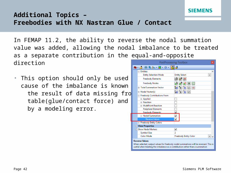
In FEMAP 11.2, the ability to reverse the nodal summation value was added, allowing the nodal imbalance to be treated as a separate contribution in the equal-and-opposite direction
• This option should only be used if the cause of the imbalance is known to be
the result of data missing from the GPFO table(glue/contact force) and not caused by a modeling error.

Page 43 Siemens PLM Software
Additional Topics – Freebodies with NX Nastran Glue / Contact
Default contributions Freebody elements / nodal summation
Freebody elements + nodal summation Reversed nodal summation

Page 44 Siemens PLM Software
Additional Topics – Load from Freebody Tool
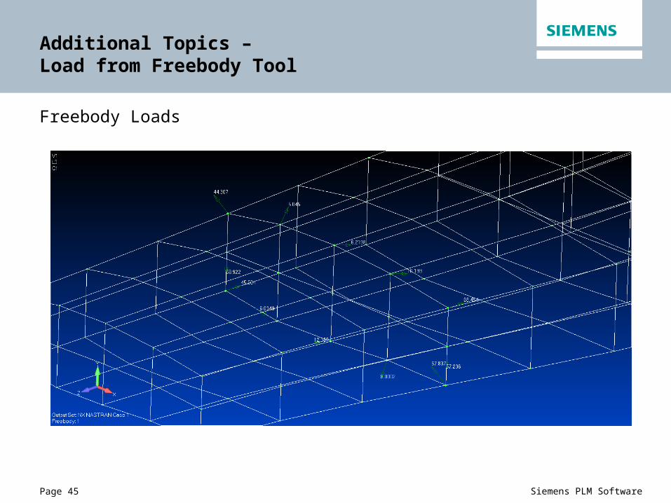
Freebody results can be used to create loads within an existing model using the Model->Load->From Freebody tool
• Works with all freebody modes• For interface load and section cut
freebodies, total summation loadcan be created at a new node in the model
• Loads can be created in an existing load set as well asin a new load set
Page 45 Siemens PLM Software
Additional Topics – Load from Freebody Tool
Freebody Loads

Page 46 Siemens PLM Software
Additional Topics – Load from Freebody Tool
Created Loads
Page 47 Siemens PLM Software
Additional Topics – Sum Data on Nodes Option
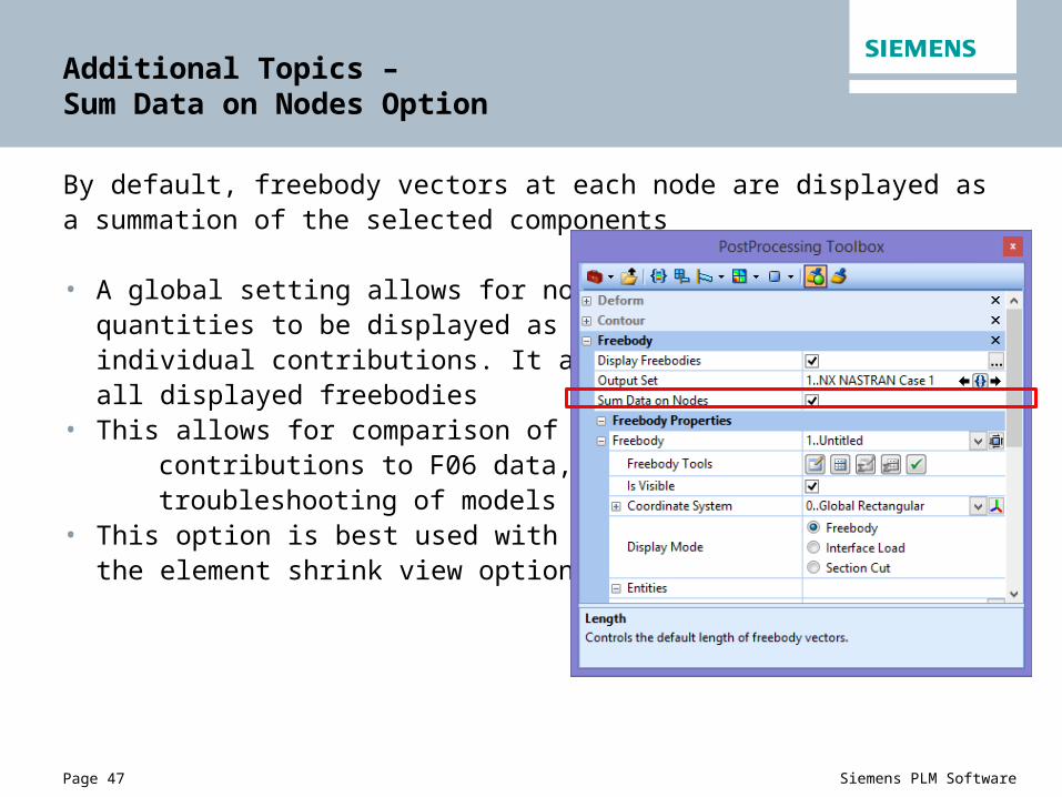
By default, freebody vectors at each node are displayed as a summation of the selected components
• A global setting allows for nodal quantities to be displayed as individual contributions. It affects all displayed freebodies
• This allows for comparison of individual contributions to F06 data, as well as troubleshooting of models• This option is best used with
the element shrink view option

Page 48 Siemens PLM Software
Additional Topics – Sum Data on Nodes Option
ID: 342Source Fx Fy Fz Mx My MzELEM 8 -4.12634 -2.76307 -130.752 46.32936 47.4351 -1.88713ELEM 182 -18.5132 142.901 -466.199 0.280101 0.999626 0.022155ELEM 80 208.315 34.15445 109.5391 0.067844 0.091289 -0.06195
Sum Data on node unchecked, element shrink display
Sum Data on node checked

Page 49 Siemens PLM Software
Q and A

Page 50 Siemens PLM Software
Siemens PLM UK SymposiumFemap Track Agenda
11:00: Femap – introduction and what’s new
11:50: Working with Femap – free bodies and global / local modeling
13:30: Femap industry customer case studies:Aerospace & marine
Customer presentationLongitude Consulting Engineers (London Offshore Consulting)
Your presenters today:
Nick Rakkar UK Channel Sales Manager, Siemens PLM SoftwareAl Robertson Product Marketing Manager, Siemens PLM SoftwareJoe Brackin Senior Software Engineer, Siemens PLM SoftwarePeter Kingsland Naval Architect, Longitude Consulting Engineers

Page 51 Siemens PLM Software
Siemens PLM UK SymposiumFemap Track Agenda
15:40: Event wrap up We will be available for questions and discussion after the event
• Femap futures and roadmap• Femap technical queries• How can Femap help in your business• Who can you talk to regarding software solution testing
Nick Rakkar – UK Channel Sales Manager
07837 553 633