UNIVERSITY OF VIRGINIA UTSIDE PLANT CABLING STANDARDS
69
University of Virginia Outside Plant Cabling Standards 1 UNIVERSITY OF VIRGINIA OUTSIDE PLANT CABLING STANDARDS
Transcript of UNIVERSITY OF VIRGINIA UTSIDE PLANT CABLING STANDARDS
University of Virginia Outside Plant Cabling Standards
1
UNIVERSITY OF VIRGINIA OUTSIDE PLANT CABLING STANDARDS
University of Virginia Outside Plant Cabling Standards
2
TABLE OF CONTENTS
SECTION PAGE
INTRODUCTION......................................................................................................................... 8
APPLICABILITY OF THESE STANDARDS .......................................................................... 9
1. Overriding Authority of the Main Body of the RFP ................................................................. 9
2. Substitution for These Specifications ........................................................................................ 9
3. Standard Industry Practice ...................................................................................................... 10
GENERAL REQUIREMENTS ................................................................................................. 11
4. Intent......................................................................................................................................... 11
5. Right-of-Way ............................................................................................................................ 11
6. Interruptions to Service ........................................................................................................... 11
7. Construction Facilities by Contractor ..................................................................................... 12
8. Plans, Position, Line, and Grade ............................................................................................. 12
9. Work Included .......................................................................................................................... 13
10. Information for UVA Project Manager ................................................................................ 13
11. Plans and Specifications ........................................................................................................ 13
12. Responsibility of Contractor .................................................................................................. 14
13. Contractor’s/Subcontractor’s Employees ............................................................................. 15
14. Safety ...................................................................................................................................... 15
15. Barricades and Lights ............................................................................................................ 16
16. Line and Grade....................................................................................................................... 16
University of Virginia Outside Plant Cabling Standards
3
17. Testing Cable .......................................................................................................................... 16
18. Decisions by UVA Project Manager ...................................................................................... 17
19. UVA Right to Do Work .......................................................................................................... 17
20. Cleaning Up............................................................................................................................ 17
SPECIAL CONSTRUCTION ................................................................................................... 18
21. General ................................................................................................................................... 18
22. Cooperation with Others ........................................................................................................ 19
23. Continuity of Existing Utility Systems................................................................................... 19
24. Survey Markers ...................................................................................................................... 19
25. Payment .................................................................................................................................. 19
EXCAVATION AND BACKFILL ............................................................................................ 20
26. General ................................................................................................................................... 20
27. Excavation for Structures ...................................................................................................... 20
28. Trench Excavation ................................................................................................................. 20
29. Rock Sawing ........................................................................................................................... 21
30. Rock Excavation (Not Recommended).................................................................................. 21
31. Rubble Excavation ................................................................................................................. 22
32. Sheeting, Shoring, and Bracing ............................................................................................ 22
33. Dewatering ............................................................................................................................. 22
34. Existing Utilities ..................................................................................................................... 23
35. Tree Removal.......................................................................................................................... 23
36. Backfill for Structures ........................................................................................................... 24
University of Virginia Outside Plant Cabling Standards
4
37. Trench Backfill ...................................................................................................................... 24
38. Surface Restoration................................................................................................................ 25
39. Street and Driveway Replacement ......................................................................................... 26
40. Field Drain Lines ................................................................................................................... 26
41. Fence Removal and Replacement ......................................................................................... 27
42. Directional Boring ................................................................................................................. 27
43. Payment .................................................................................................................................. 27
PIPES AND STRUCTURES ...................................................................................................... 29
44. Pipe Materials ........................................................................................................................ 29
45. Pipe Joints .............................................................................................................................. 29
46. Joint Protection and Inspection ............................................................................................ 29
47. Pipe Installation ..................................................................................................................... 29
48. Connections between Dissimilar Pipes ................................................................................. 30
49. Pipe Conflicts ......................................................................................................................... 30
50. Tracer Wire Installation ........................................................................................................ 30
51. Proofing the Duct ................................................................................................................... 31
52. Multiple Duct Installation ..................................................................................................... 31
53. Manholes/Hand-Holes ........................................................................................................... 31
54. Payment .................................................................................................................................. 31
55. Bedding Requirements ........................................................................................................... 32
SPECIFICATIONS FOR BURIED INSTALLATION OF FIBER OPTIC CABLE ........... 33
57. General ................................................................................................................................... 33
University of Virginia Outside Plant Cabling Standards
5
58. Material .................................................................................................................................. 33
59. Bridge Attachments ................................................................................................................ 33
60. Protection of Material ............................................................................................................ 34
61. Reporting Cable Damage ....................................................................................................... 34
62. Cable Repairs ......................................................................................................................... 34
63. Depth of Burial....................................................................................................................... 35
64. Cable Marking Ribbon .......................................................................................................... 36
65. Hand-Holes (Splice Boxes) .................................................................................................... 36
66. Cable Plowing ........................................................................................................................ 37
67. Plowing Equipment Requirements ........................................................................................ 37
68. Plowing Requirements ........................................................................................................... 38
69. Plowing Precautions .............................................................................................................. 39
70. Cable Plowing in Rock Areas ................................................................................................ 40
71. Placing Cable at Reel Ends ................................................................................................... 40
72. Cable in Trench ...................................................................................................................... 40
73. Duct Installation .................................................................................................................... 42
74. Cable Pulling .......................................................................................................................... 42
75. Subsurface Obstructions ........................................................................................................ 42
76. Inspection of Buried Cable .................................................................................................... 43
77. Highway, Railroad, and Other Bored Crossings .................................................................. 43
78. Stream and Canal Crossings ................................................................................................. 44
79. Cable Markers ........................................................................................................................ 46
80. Right-of-Way Protection and Restoration ............................................................................. 46
University of Virginia Outside Plant Cabling Standards
6
81. Coexistence on Highway Right-of-Way ................................................................................ 47
82. Fencing ................................................................................................................................... 48
83. Building Specifications .......................................................................................................... 49
84. Splicing ................................................................................................................................... 50
85. Concrete .................................................................................................................................. 51
86. Material Requirements .......................................................................................................... 51
SPECIFICATIONS FOR AERIAL PLACEMENT OF FIBER OPTIC CABLE ................ 54
87. General ................................................................................................................................... 54
88. Placement ............................................................................................................................... 54
89. Lashed Aerial Plant ............................................................................................................... 57
SPLICING AND TESTING ....................................................................................................... 61
90. General ................................................................................................................................... 61
91. Access to Work ....................................................................................................................... 61
92. Material .................................................................................................................................. 61
93. Pre-Placement Cable Testing ................................................................................................ 62
94. Ultimate Responsibility .......................................................................................................... 62
95. Splices ..................................................................................................................................... 62
96. Loss Specifications ................................................................................................................. 63
97. Splicing at Active Locations .................................................................................................. 63
98. Testing .................................................................................................................................... 64
99. Acceptance Criteria ................................................................................................................ 65
100. Markers................................................................................................................................. 65
University of Virginia Outside Plant Cabling Standards
7
101. Documentation ..................................................................................................................... 65
AS-BUILT DRAWINGS ............................................................................................................ 67
102. Introduction .......................................................................................................................... 67
103. Specific Requirements.......................................................................................................... 68

University of Virginia Outside Plant Cabling Standards
8
Introduction
This document establishes standards for the installation and maintenance of telecommunications outside plant cabling at the University and supersedes “UVA Wiring Standard: Standards for Building Telecommunications Facilities” issued by Information Technology Services (September 2005) and "Recommendations for Telecommunications Wiring Guidelines" issued by the Data Communications Working Group (July 11, 1990). While the standards are meant to apply particularly to new construction and major renovation projects, they should also be followed when working with existing outside plant whenever it is practical and economically feasible. Information Technology Services will act as telecommunications consultant and review the plans for all University construction and renovation projects. In buildings where Health Information and Technology Computing Services (HI&T) or Health Services Foundation operate networks, these departments will also act as consultants and review telecommunications plans.
It is recognized that the design process and the allocation of space in all construction and renovation projects is actually a negotiation between all interested parties. These standards provide information for the initial project design. Once the initial phase is complete, ITS and the other consultants will work with other University stakeholders to perform the detailed work and ensure that cable plant supporting a modern network infrastructure can be installed. ITS and the other reviewers will always be flexible and make sure that the needs of University community are met at the minimum possible cost.
Reference material used in preparing this document includes the Telecommunications Industry Association’s TIA-758-B: Customer-Owned Outside Plant Telecommunications Infrastructure Standard. The Standard may be obtained at, http://www.tiaonline.org/standards/ The University’s standards take precedence over all others.

University of Virginia Outside Plant Cabling Standards
9
Applicability of These Standards
1. Overriding Authority of the Main Body of the RFP
1.1 If this document is used in combination with a Request for Proposal (RFP), then the following sections are applicable. 1.2 The specifications and requirements in this University of Virginia Outside Plant Cabling Standards (UVA OSPCS) are intended to supplement and amplify the more general specifications and requirements stated in the main body of the RFP. 1.3 If there are any conflicts or areas of ambiguity, the specifications and requirements stated in the main body of the RFP shall override any specifications and/or requirements stated in this UVA OSPCS, notwithstanding any erroneous written denial the UVA Project Manager may issue under subparagraph 1.3 of this document. 1.4 For the sake of clarity and to ensure that the Contractor is aware of the appropriate specification and/or requirement to use in specific circumstances, Contractor should identify, in writing, how a specification or requirement in this UVA OSPCS conflicts with any specification or requirement in the main body of the RFP or with any standard or code specified in Section 2.1 of the RFP. The UVA Project Manager will review Contractor’s statement and, within five (5) business days, issue a written acceptance of Contractor’s statement or a written denial with explanation. If Contractor disagrees with the UVA Project Manager’s denial, Contractor may appeal to the University of Virginia’s Chief Information Officer, whose decision is final.
2. Substitution for These Specifications
2.1 Contractor may use different specifications and/or requirements than those stated in this UVA OSPCS if:
2.1.1 They do not conflict with the main body of the RFP. 2.1.2 They do not conflict with any standard or code specified in Section 2.1 of the RFP. 2.1.3 Contractor can provide a rationale for using a different specification or standard. 2.1.4 Contractor has obtained written approval from the UVA Project Manager for use of the alternative specification or requirement.
University of Virginia Outside Plant Cabling Standards
10
2.2 Notwithstanding the UVA Project Manager’s written approval for Contractor’s usage of an alternative specification or requirement, Contractor will still be liable for technical failure of a Span, regardless of whether such failure is due, in part or in whole, to Contractor’s substitution of a specification or requirement under this Section 2.2 of UVA OSPCS. Contractor will be responsible for the remediation of such failure at Contractor’s own expense.
3. Standard Industry Practice
3.1 In the event that neither the main body of the RFP nor this UVA OSPCS describes a specification or requirement that should be used in specific circumstances, Contractor should use the appropriate standard or code specified in Section 2.1 of the RFP or, in the absence of such a reference, standard industry practice. Written approval from the UVA Project Manager is not required. 3.2 Contractor will still be liable for technical failure of a Span within the provided warranty period. In such circumstances, Contractor will be responsible for the remediation of such failure at Contractor’s own expense.
University of Virginia Outside Plant Cabling Standards
11
General Requirements 4. Intent
4.1 To supplement the provisions of the RFP, by outlining special conditions applicable to projects. 4.2 To set forth requirements of performance, type of equipment or structure desired, and standards of materials and construction. 4.3 To describe work set out in Contract Documents, unless otherwise specifically indicated. 4.4 To require performance of complete work in spite of omission of specific reference to any minor component parts. 4.5 Contractor will provide for new materials and equipment unless otherwise indicated.
5. Right-of-Way
5.1 Contractor will support the UVA Project manager in providing information to obtain permits from departments and/or agencies of city, state, county, and federal governments, railroads, and other entities that provide for the placement of facilities within their respective rights of way, unless otherwise indicated.
5.2 Confine movements of equipment and personnel, storage of materials, excavation, and all other construction operations within the right-of-way provided. 5.3 Contractor will be held liable by Virginia Department of Transportation, local government jurisdictions, schools, and adjacent property owners for damages outside of rights-of-way and easements. 5.4 Ingress and egress will vary according to right-of-way agreements. If necessary, the Contractor will provide gates in fences and remove after completion. 5.5 On freeways, installation must be accomplished without entering the through traffic roadway or ramps. No vehicles, equipment or materials shall be parked or stored upon any portion of the median, through traffic roadway and ramps or shoulders thereof or within the clear zone.
6. Interruptions to Service

University of Virginia Outside Plant Cabling Standards
12
6.1 Existing utilities will remain in continuous operation during construction. 7. Construction Facilities by Contractor
7.1 Provide telephone at which Contractor can be reached by the UVA Project Manager at all times during the working day.
7.1.1 Provide the UVA Project Manager with at least two telephone numbers where Contractor’s representative can be reached evenings, weekends and holidays in event of emergency. Place on construction schedule.
7.2 Location of all construction facilities, including storage yard, subject to approval by the UVA Project Manager; remove all construction facilities upon completion of work. 7.3 Provide and maintain suitable sanitary facilities for construction personnel for duration of work; remove upon completion of work. 7.4 Provide fence, barricades, and/or watchmen to prevent access of unauthorized persons to site where work is in progress.
8. Plans, Position, Line, and Grade
8.1 Contractor shall provide UVA Project Manager with one set of plans and specifications (to include “Construction Drawings”) within forty (40) business days after execution of Contract unless otherwise stated in RFP. 8.2 Contractor shall provide the UVA Project Manager with additional and supplemental plans as may be required to show details of construction after approval of Contractor’s Construction Drawings and data on materials and equipment. 8.3 Contractor shall provide the UVA Project Manager with such revised plans and specifications as may be required to show any authorized changes or extra work. 8.4 Contractor shall construct to lines and grades shown on plans or as specified hereinafter. 8.5 Contractor shall establish required benchmarks and base lines as shown on plans. 8.6 Contractor to provide detailed survey and staking for location and elevation of construction.
University of Virginia Outside Plant Cabling Standards
13
8.7 Contractor shall provide, without extra compensation, all people and necessary tools to make all test holes and exploration, at any time, for purpose of determining location of existing structures beneath ground surface that might conflict with work of Contractor. 8.8 Contractor shall preserve all monuments, reference points, stakes, and benchmarks set by other entities. In case of destruction by Contractor’s negligence or carelessness, Contractor will be charged with resulting expense of replacement and responsibility for any mistake or loss of time caused thereby.
9. Work Included
9.1 Furnish all plans, materials, labor, and equipment to construct as set out in the RFP, specific Work Order to which the Contractor responded, and the Contractor’s response to the RFP.
10. Information for UVA Project Manager
10.1 After award of contract, submit the following information and Construction Drawings for the UVA Project Manager’s review: manufacturer’s specifications and catalog data for material and such other data as requested by RFP or specific Work Order. 10.2 Within 40 business days after award of contract or specific Work Order, provide construction schedule showing start and completion of various portions of work and construction plans.
10.2.1 Purchase orders and subcontracts without prices. 10.2.2 All materials test reports. 10.2.3 Proposed equipment and method for boring/jacking; details of boring/jacking pit. 10.2.4 Proposed equipment and method for trenching. 10.2.5 Proposed equipment and method for plowing. 10.2.6 Construction plans, unless otherwise indicated, including location of facility in relationship to established landmarks.
11. Plans and Specifications
11.1 Contractor will furnish two (2) sets of plans and specifications to the UVA Project Manager after award of contract unless otherwise stated in RFP or specific Work Order.
University of Virginia Outside Plant Cabling Standards
14
11.2 Contractor will provide one set of plans and specifications for each foreman or superintendent in charge of each crew on job.
12. Responsibility of Contractor
12.1 Protection of Contractor’s work. 12.2 Protection of all property from injury or loss resulting from Contractor’s operations. 12.3 Replace or repair objects sustaining any such damage, injury, or loss to satisfaction of the UVA Project Manager. 12.4 Without limiting these General Requirements (Sections 4 through 20 of this UVA OSPCS), protect flagpoles, sidewalks, streets, pavements, fences, pipe, conduit, utilities, trees, shrubs, and structures. 12.5 Cooperate with the UVA Project Manager and representative of utilities in locating underground utility lines and structures; incorrect, inaccurate, or inadequate information concerning location of utilities or structures shall not relieve Contractor of responsibility for damage thereto caused by Contractor’s operations. 12.6 Contractor will locate underground lines of third parties in the cable route area. Contractor will call the Virginia 811 (VA811) System, commonly called Miss Utility of Virginia or an appropriate alternative prior to any work commencement. Contractor will directly contact any utilities not participating in the VA811 System. Contractor will hold a single locate “precon meeting” for all utilities. It will be the Contractor’s responsibility to document the name, address, phone, and fax number of all persons present at meeting plus the location confirmation number by project. All the aforementioned documentation will be supplied to the UVA as part of the “as built” package. Contractor will be responsible for hand digging any crossing such as pipeline, drainage tile, cable, or any other buried facility prior to working in the area. Since all drawings are generally diagrammatic and not all utilities are included on them, the Contractor will take every precaution necessary to avoid damage to any underground facility. 12.7 Keep cleanup current on a daily basis with construction operations. 12.8 Comply with all federal, state, and city laws and ordinances. 12.9 Contractor shall assume full responsibility for safekeeping of all materials and equipment and for all unfinished work until final acceptance by the UVA Project Manager. Materials and equipment that are damaged or destroyed from any cause shall be replaced at Contractor’s expense.
University of Virginia Outside Plant Cabling Standards
15
12.10 Contractor shall issue written receipts for all such property and account to UVA for any damage to or loss of such property while in its custody or control. 12.11 If UVA is providing warehousing with security for cable, conduit, and other OSP materials on a temporary basis, it will be the responsibility of the Contractor to arrange for their own storage facilities and delivery of material from the HCP’s warehouses. Should a Contractor elect to provide its own storage facilities in its particular area, then Contractor will be solely responsible for any materials supplied to that facility by UVA. The UVA may require the subcontractor to furnish Builders Risk Insurance for this material at the Contractor's expense. Security for the job site areas is the responsibility of the Contractor. Subcontractor is to comply with the security requirements of Owner’s site security and other applicable entities.
13. Contractor’s/Subcontractor’s Employees
13.1 Contractor shall personally supervise subcontracted work or provide a capable superintendent satisfactory to the UVA Project Manager. Superintendent shall be authorized to receive instructions from the UVA Project Manager or his or her representative. 13.2 Contractor/subcontractor shall have its company name clearly displayed on each owned or leased vehicle and on all equipment. 13.3 Each contractor/subcontractor employee shall carry a business card with his or her employer’s company name, phone number, and fax number listed. 13.4 Contractor/subcontractor shall at all times be deemed to be representing and/or performing as an independent contractor and not as an agent or employee of UVA.
14. Safety
14.1 No job is so urgent that one cannot take time to perform work safely. 14.2 Safety is the foremost concern in any contract operation. Unsafe acts or operations will not be tolerated, to the point of termination of the Contract. 14.3 Compliance with all Federal, State, and local laws, ordinances, and regulations concerning health and safety is mandatory. 14.4 Hard hats must be worn by all personnel in installation areas at all times.
University of Virginia Outside Plant Cabling Standards
16
14.5 During work in right-of-ways of interstate, secondary, and other roadways, hard hats and reflective vests will be worn. 14.6 Traffic cones, flagmen, and warning signs will be inspected each day at each work site. 14.7 Contractor will provide evidence that a written Confined Space Procedure, complying with the latest OSHA standards, will be adhered to. The Contractor will provide a copy of its written procedure to UVA prior to any work that may involve entering a confined space. 14.8 All excavations left unattended or open shall be properly barricaded or plated (steel plate if in the street) until temporarily backfilled or complete restoration has been performed. During any non-working hours, Contractor shall place steel plates over any open trenches that would pose a threat to vehicular traffic. The steel plates shall be of sufficient thickness to withstand the weight of a vehicle and anchored in place to prevent movement. Open trenches and holes, not exposed to vehicular traffic, will be encircled by flexible orange snow fence and shall also be covered with plywood (or equal) and anchored in place. Plywood (or equal) shall be of sufficient thickness to withstand the weight of the anticipated traffic.
15. Barricades and Lights
15.1 All signs, barricades, lights, and other traffic control devices used on the project shall be furnished, installed, and maintained by Contractor; all traffic control devices shall be maintained in a state of good repair and shall be cleaned and washed periodically as needed.
16. Line and Grade
16.1 Contractor shall provide benchmarks, base lines, and other reference points. Contractor shall provide competent men and tools, stakes, and other materials as required, establishing temporary or permanent reference marks in connection with the work. Contractor shall perform such detailed measurements as required to properly lay out and construct work.
17. Testing Cable
17.1 The Contractor/Subcontractor shall be responsible for on-reel verification of cable quality prior to placement. 17.2 Completed test forms on each reel shall be submitted to the UVA Project Manager. 17.3 Contractor assumes responsibility for the cable after testing. This responsibility covers all fibers in the cable.
University of Virginia Outside Plant Cabling Standards
17
17.4 The Contractor shall supply all tools, test equipment, consumables, and incidentals necessary to perform quality testing. 17.5 The cable ends shall be sealed upon completion of testing.
18. Decisions by UVA Project Manager
18.1 The UVA Project Manager shall make decisions, in writing, on claims between Contractor and UVA within a reasonable time after presentation. Such decisions shall be regarded as final except for appropriate legal recourse.
19. UVA Right to Do Work
19.1 If Contractor neglects to prosecute work properly or fails to perform any provision of this contract, the University, after three (3) days’ written notice to Contractor, may, without prejudice to any other remedy it may have, make good such deficiencies and may deduct the cost thereof from the payment then or thereafter due the Contractor from the University, provided, however, that the UVA Project Manager shall approve both such action and amount charged to Contractor.
20. Cleaning Up
20.1 Contractor shall keep premises free from accumulations of waste material or rubbish caused by its employees or work. After completion of work, it shall remove all its rubbish and all its tools, scaffolding, and surplus materials from work site. It shall leave its work “broom clean” or its equivalent, unless more exactly specified. In case of dispute, the UVA may remove rubbish and charge cost to Contractor, as the UVA Project Manager shall determine to be just.
University of Virginia Outside Plant Cabling Standards
18
Special Construction 21. General
21.1 Procedures outlined below are not intended to fully cover all special procedures or emergencies which may arise during construction. Contractor will cooperate with government entities, hospitals, schools, and other institutions to minimize inconvenience, construction delays, and interruptions to continuous operation of existing fiber facilities. 21.2 Determine location of all underground utilities before starting excavation work; locations of underground appurtenances are approximate and not guaranteed by UVA. 21.3 Remove and replace all signs and other appurtenances that interfere with construction operations; replace damaged signs at no cost to UVA. 21.4 Limit construction operations to all provided property, rights-of-way, and easements. Provide barricades, lights, signs, and detours as necessary to reroute traffic around construction areas. 21.5 Arrange with operating utilities for relocation or temporary removal of utilities in conflict with construction and for service needed during construction, at no cost to UVA. 21.6 Dispose of materials removed during construction at locations as approved by Contractor’s Engineer.
21.6.1 Dispose of waste products containing prescribed materials at approved landfill. 21.6.2 Dispose of surfacing, broken concrete or rubble, excess excavated materials, and spoil. 21.6.3 Place excess excavated material at locations designated by Contractor’s Engineer.
21.7 Notify businesses and residents two days in advance when construction will disrupt or block access to property. 21.8 Provide snow fence along boundaries of construction area as specified hereinafter and as directed by the UVA Project Manager.
21.8.1 Install snow fence when area is prepared for excavation. Install on steel posts with maximum spacing of 8’. Maintain until work is complete.

University of Virginia Outside Plant Cabling Standards
19
21.8.2 Provide snow fence around all open trenches or open structures when left unattended. 21.8.3 Provide snow fence to keep livestock away from construction
21.9 Backfill trench as construction progresses. 21.10 Cleanup and provide surface restoration as work progresses. 21.11 Protect survey markers of lot corners.
22. Cooperation with Others
22.1 Advise all utilities (telephone, electrical power, natural gas, water, cable television, et al.) prior to excavating in area where construction might affect underground telephone, electrical power, natural gas, water, cable television, or other service. Advise each utility of proposed construction schedule as it relates to services the utility provides.
23. Continuity of Existing Utility Systems
23.1 Prepare detailed construction procedure schedule after award of contract: show definite and positive action to be taken to minimize disruption to utility systems. 23.2 Meet with all utilities to determine operability of isolation to determine area for which service would be shut off for each utility.
24. Survey Markers
24.1 Contractor is responsible for hiring registered land surveyor to inventory existing pipe, pins, and registered survey lot corners disturbed by construction. Land surveyor is responsible for setting reference markers required to reestablish location of existing pipe, pins, and registered survey lot corners. Land surveyor will not be required to certify pins or pipe replace as being lot corners. Replace all markers disturbed by construction, including where more than one pipe, pin, or other marker are present at a location, replacing all markers in same location as removed. Provide drawing to UVA showing locations where markers were found and reset (dimensional data not required on drawing). Each pipe, pin, or marker replaced must be the identical marker removed at that location.
25. Payment
25.1 No separate payment will be made for work covered under this part of the Specifications.
University of Virginia Outside Plant Cabling Standards
20
Excavation and Backfill 26. General
26.1 Protect existing pavement from damage during construction if not being removed; if damage occurs, replace in kind at no cost to UVA. 26.2 Remove, replace, and repair items such as fences, storm drains, signs, hanging wires, and other obstructions to accommodate construction equipment or to facilitate excavation; cost to remove and replace is incidental to construction. 26.3 Haul away and stockpile excavated material suitable for backfill; haul remainder of excavated material to an authorized waste site. 26.4 Remove soil not suitable for backfill; removal is incidental to construction. 26.5 Where new work crosses existing utilities or utility services, excavate in advance of construction; determine crossing arrangement including exact construction line and grade. As specified in Section 12, “Responsibility of Contractor.” 26.6 Bore or jack under existing streets, utilities, and structures except as noted on plans or as modified by the UVA Project Manager.
27. Excavation for Structures
27.1 Includes excavation for manholes and other appurtenances. 27.2 Excavate as required to firm, undisturbed soil for laying conduit. In the case of hand-holes/manholes, excavate six (6”) inches below bottom of structure and fill with six (6”) inches of ¾” river rock at no expense to UVA. 27.3 Provide sheeting, shoring, and bracing where required to hold walls of excavation or to protect existing structures or utilities. 27.4 When unstable material is encountered which will not, in the opinion of the UVA Project Manager, provide suitable foundation, remove and replace with granular stabilizing material as directed by the UVA Project Manager in writing, cost incidental to construction.
28. Trench Excavation
University of Virginia Outside Plant Cabling Standards
21
28.1 Keep width of trench as narrow as possible and still provide adequate room for backfilling and jointing. 28.2 Keep sides of trench as nearly vertical as practicable; comply with federal and state safety regulations. 28.3 Excavate by hand:
28.3.1 Under and around utilities. 28.3.2 Where overhead clearance prevents use of machines. 28.3.3 To protect trees and shrubs.
28.4 Remove top 18” of topsoil and store in segregated stockpiles for backfill prior to trench excavation. 28.5 The trench shall be as straight as practical. The bottom of the trench shall be smooth and free from any sharp edges. The trench shall be kept clear of debris and loose rock. All changes in trench grade shall be gradual. 28.6 The length of open trench shall not exceed 100’ feet at the end of each working day. Any open trench, bore pit, or pothole shall be fenced, covered, or otherwise barricaded to protect the general public at all times. Exceptions are subject to approval by the UVA Project Manager. Good judgment and care must be exercised to prevent persons from falling into the open trench, or other damages.
29. Rock Sawing
29.1 Solid rock is defined as a consolidated rock that cannot be plowed to the specified depth. Frozen ground is not considered solid rock. 29.2 Where solid rock is encountered, the cable will be protected by steel, PVC conduit, or high-density polyethylene conduit (HDPE) at the discretion of the UVA or its authorized representative.
30. Rock Excavation (Not Recommended)
30.1 Use of explosives: submit detailed plans outlining all proposed blasting operations, locations, methods, and use of mats and other safety measures.
University of Virginia Outside Plant Cabling Standards
22
30.1.1 Obtain written approval from the UVA Project Manager and Contractor’s Engineer before using explosives. 30.1.2 Provide Special Hazard Insurance covering liability for all blasting operations. 30.1.3 Use thoroughly experienced demolition personnel.
31. Rubble Excavation
31.1 Rubble, as specified and defined herein, may be encountered along the route.
31.2 Removal: as specified for rock. 31.3 Use of explosives: as specified for removal of rock.
32. Sheeting, Shoring, and Bracing
32.1 Minimum shoring requirement: equivalent construction procedure to use of “sand box” to provide 8’ vertical protection; provide stacked sand boxes as required to maintain construction within construction limits. 32.2 Construct sheeting, shoring, and bracing to hold walls of excavation to provide safety for workmen, to protect existing utilities or structures, or to permit construction in the dry. Sheeting operations which, in the opinion of the UVA Project Manager, cause excessive vibration will not be allowed. 32.3 Leave sheeting and shoring in place when removal, in the opinion of the UVA Project Manager, might damage new facility, existing utilities, or structures. 32.4 Sheeting, shoring, and bracing are incidental to construction; include cost in appropriate unit cost.
33. Dewatering
33.1 All work must be done in a dry environment; if the method of dewatering might raise concerns, obtain the UVA Project Manager’s approval. 33.2 Provide for handling of water encountered during construction. 33.3 Lay no pipe/fiber in or pour no concrete on excessively wet soil. 33.4 Prevent surface water from flowing into excavation; remove water as it accumulates.
University of Virginia Outside Plant Cabling Standards
23
33.5 Divert stream flow away from areas of construction. 33.6 Do not pump water onto adjacent property without approval of the UVA Project Manager. 33.7 Dewatering is incidental to construction; include cost in appropriate unit cost.
34. Existing Utilities
34.1 Hold a preconstruction meeting 3 days prior to beginning construction. Document meeting with a sign-in sheet detailing names, addresses, and phone & fax numbers of company representatives present. Take minutes of meeting and provide documentation with as-built package. 34.2 Locations of utility lines, mains, cables, and appurtenances are the responsibility of Contractor. Confirm locations of underground utilities by excavating ahead of work. Contractor is fully responsible for damage to utilities during construction. 34.3 Protect services during construction.
34.3.1 If utility services are in direct conflict with line and /or grade of new facility, notify UVA immediately; provide all necessary shut-down, repair, and relocation where conflicts occur; furnish labor, equipment, pipe, and fittings; repair and relocation will be paid by Contractor; when broken due to carelessness, repair is incidental to construction. 34.3.2 Support and protect, by timbers or other means, all utility pipes, conduits, poles, wire, and other apparatus that will not be moved; protective measures are subject to the approval of the UVA Project Manager. 34.3.3 No utility or utility service will be moved to accommodate equipment employment, to accommodate method of operation, or for the convenience of Contractor when utility or utility services does not conflict directly with line and grade of work.
35. Tree Removal
35.1 All tree removal must be approved by the UVA Project Manager. Trees should be removed only when in conflict with alignment of trenches or location of structures. 35.2 Removal includes grubbing and removing stump and roots, removal from site, disposal of debris, and backfilling.
University of Virginia Outside Plant Cabling Standards
24
35.3 Tree and bush removal is incidental to construction; include cost in applicable unit price.
36. Backfill for Structures
36.1 Backfill after concrete, masonry, or glue has cured, and waterproofing, if specified, has been inspected and approved by the UVA Project Manager and Contractor’s Engineer. 36.2 Backfill with material removed from excavation; use no debris, frozen earth, large clods, stones, or other unsuitable material. 36.3 Backfill simultaneously on all side of structure; save structure from damage at all times. 36.4 Terminate at original grade or at elevation shown on plans; dispose of excess excavation as directed by Contractor’s Engineer. 36.5 Prepare backfill for surface restoration as specified for adjacent trench.
37. Trench Backfill
37.1 Backfill trench immediately after Contractor has recorded sequence marking on cable or location of connections and appurtenances or at the UVA Project Manager’s direction; backfill with select material excavated from trench. 37.2 Use no large stones, large clods, organic matter, rubbish, or frozen or unsuitable materials in backfill; furnish extra soil from site to complete backfilling at no extra cost to UVA; remove and dispose of unsuitable material; backfill simultaneously on both sides of pipe to prevent displacement. 37.3 Hand place and carefully compact backfill to 1’ over top of facility. 37.4 Backfill 1’ over top of facility in layers not to exceed 18”; where compacted backfill is shown on plans, compact to minimum 95% maximum density. 37.5 Backfill above PVC pipes:
37.5.1 Backfill with pipe bedding material to minimum 6” above top of pipe; do not drop pipe bedding material from equipment bucket more than 2’ above pipe; all pipe bedding material, including backfill material, is incidental to construction. 37.5.2 Above pipe bedding material, backfill with excavated material, except frozen material, shale, and other non-suitable material; do not drop backfill material from
University of Virginia Outside Plant Cabling Standards
25
equipment bucket more than 2’ above bottom of trench until backfill material is in place 18” above bedding backfill material. 37.5.3 Consolidate bottom 6” of trench backfill with hand tools and tampers; do not use vibratory plate compactor until above bottom 18” of trench backfill. 37.5.4 Cable marking ribbon shall be installed above all trenched direct-buried HDPE/conduits. The ribbon shall generally be placed at a depth of 12” inches below grade and directly above the fiber/HDPE/conduits. 37.5.5 Splice boxes/hand-holes will be placed at all splice locations. Hand-holes will be placed at intervals of approximately 1,000’ feet, change of direction greater than 15%, and as shown on Construction Drawings and typical drawings. Hand-holes may be moved to locations more practical when necessary upon approval by the UVA Project Manager.
38. Surface Restoration
38.1 All trenches: replace 18” of topsoil removed during excavation. 38.2 Grade tops of trenches to smooth, uniform lines without large lumps, clods, or debris. 38.3 Dispose of all brush and rubbish in accordance with Section 21.9 of this UVA OSPCS; removal is incidental to construction. 38.4 Sod/seed all areas disturbed by construction unless otherwise shown on plans or as directed by the UVA Project Manager. 38.5 Prepare site for seeding by disking, harrowing, and hand raking, or by other means, following site grading; work soil to depth of 3”. 38.6 Precede seeding with uniform application of commercial grade fertilizer at rate per acre of 20 lbs. of nitrogen, 40 lbs. of phosphorous, and 20 lbs. of potassium (400 lbs. of fertilizer grade 5-10-5 per acre, or approved equal), or as appropriate for soil type and climate; cultivate area 3” deep and work with harrow within 24 hours before seeding; smooth surface to eliminate clods and lumps before seeding. 38.7 Seeding in street parking, lawns, and developed areas (Type 1): Seed at rate of 85 lbs. per acre. 38.8 Seeding in City rights-of-way, railroad rights-of-way, pastures, farm fields, and creek banks (Type 2). Seed at the rate of 1.25 lbs. per 1,000 square feet.
University of Virginia Outside Plant Cabling Standards
26
38.9 Seed between dates of August 15 and October 15 or between dates of April 1 and May 30. 38.10 Cover seed by rolling with cultipacker, or by dragging or hand raking. 38.11 Mulch all seeded areas. Mulch: dry oat straw at a rate of 4,000 lbs. per acre. Stabilize mulch with tiller designed to anchor mulch to soil. 38.12 Water seeded area sufficiently to saturate seed bed; continue watering all areas until growth is established. 38.13 Contractor is responsible for growing a full stand of grass; replant or redevelop bare spots or areas not attaining full stand of grass during first growing season. 38.14 No separate payment will be made for work covered in this part of the specifications.
39. Street and Driveway Replacement
39.1 Replace surface with new surfaces to match construction for type, size, and surface texture unless otherwise specified. 39.2 Gravel or crushed stone:
39.2.1 Place 6” compacted crushed stone in top of trench and compact in two lifts. 39.2.2 Place additional compacted crushed stone beyond trench limits to widths shown on plans to restore to existing conditions; minimum thickness of 2”. 39.2.3 No separate payment will be made for work covered in this part of the specifications.
40. Field Drain Lines
40.1 Field drain lines may be encountered along route of new sewer; notify the UVA Project Manager if drain conflicts with facility construction. 40.2 Where new facility crosses under field drain lines, replace with a length of Schedule 40 PVC pipe; match size of existing drain line; cut 1/8” to ¼” wide slots at 12” centers transverse to pipe for slots on bottom; replacement paid for by Contractor. 40.3 Where new facility parallels field drain lines, replace damaged field drain lines; match size and material of existing drain line.
University of Virginia Outside Plant Cabling Standards
27
40.4 No separate payment will be made for work covered in this part of the specifications.
41. Fence Removal and Replacement
41.1 Remove fence for construction access as required within easements. 41.2 Miscellaneous fence removal and replacement is incidental to construction; restore fence to original or better condition; replace wooden fence posts with new posts unless directed otherwise by the UVA Project Manager or Contractor’s Engineer. 41.3 No separate payment will be made for work covered in this part of the specifications.
42. Directional Boring
42.1 This includes all labor, equipment, and materials to install a minimum of one 1.25-inch-diameter HDPE using directional boring techniques. The running line of the duct shall be kept straight and level unless otherwise specified in the final Construction Drawings. Any changes, either vertical or horizontal, shall be gradual and not to exceed 1.5” (inches) deviation in less than 6” (inches). Special care shall be taken to insure that the duct connection between bores be kept straight and level. When installing inner-ducts, conduits shall be color coded or marked to aid in identifying the respective ducts. This color-coding shall be observed during connection to assure duct continuity. 42.2 This unit also includes any pothole excavation for whatever purpose along with the pothole restoration. The barricading and safeguarding of pothole excavations shall comply with the Excavation and Backfill sections of this UVA OSPCS (Sections 26 through 43). Backfill and restoration of excavation shall comply with Federal, State, or local governing agency requirements. 42.3 Entrance of HDPE conduits into manholes and hand-holes/splice boxes shall be in a level and straight line to facilitate installation of fiber optic cable. 42.4 Every effort shall be made to maintain a minimum of twelve (12”) inches of clearance between HCP’s conduit and other utilities. 42.5 The boring machine shall be grounded at all times during operation. The grounding method shall comply with the manufacturer’s guidelines and requirements. Adequate barricades shall be erected to limit access to boring machine operation personnel only.
43. Payment
University of Virginia Outside Plant Cabling Standards
28
43.1 No separate payment will be made for work covered in this part of the specifications.
University of Virginia Outside Plant Cabling Standards
29
Pipes and Structures 44. Pipe Materials
44.1 Polyvinylchloride pipe (PVC) 44.2 Steel casing pipe: 0.25” under roadway; use for casing pipe where shown on plans. 44.3 HDPE 44.4 Plenum raceway
45. Pipe Joints
45.1 Polyvinylchloride (PVC) schedule 40: couplings and/or integral bell 45.2 HDPE connectors: approved by the manufacture 45.3 Steel pipe 45.4 Plenum connectors approved by the manufacture
46. Joint Protection and Inspection
46.1 Carefully protect joints from injury while handling and storing pipe. 46.2 Use no deformed, gouged, or otherwise impaired joints. 46.3 Clean bell and spigot surface of dirt and foreign matter before jointing pipe. 46.4 Use cleaner or primer. 46.5 Make joints in strict accordance with manufacturer’s recommendations.
47. Pipe Installation
47.1 All inner-duct, HDPE or conduit shall be tagged or color-coded. 47.2 Before laying pipe, verify all measurements at site; make necessary field measurements to accurately determine pipe make-up lengths or closures.
University of Virginia Outside Plant Cabling Standards
30
47.3 Keep pipe free of all dirt and foreign material 47.4 Use no defective pipe; check each length for defects and hairline cracks at ends prior to lowering into trench. 47.5 Lower pipe carefully into trench. 47.6 Pull joints together with equipment recommended by pipe manufacturer; do not use backhoe or similar equipment to push joints together.
48. Connections between Dissimilar Pipes
48.1 Provide manufactured adaptor or coupling. 49. Pipe Conflicts
49.1 Where pipe parallels an existing facility, maintain at least 1 foot of separation. 49.2 Where pipe crosses an existing facility, maintain at least 1 foot of separation. 49.3 Provide all necessary shut-down, repair, and relocation of existing facilities where conflicts occur; furnish labor, equipment, pipe, and fittings; repair and relocation will be paid by Contractor. When existing facility is damaged due to carelessness, repair is incidental to construction. 49.4 Resolve conflicts as specified in Sections 26 through 43 of UVA OSPCS, “Excavation and Backfill.”
50. Tracer Wire Installation
50.1 Tracer wire shall be placed with all HDPE conduit installed unless armored or traceable cable is used. The Contractor will provide the tracer wire and shall install, splice, and test (for continuity) the tracer wire. If the tracer wire is not placed or is broken during installation, the Contractor shall notify the UVA Project Manager immediately. The area of the route that does not have tracer wire installed shall be identified on the as-built documents submitted by the Contractor. 50.2 For multi-duct installation, install a 5/8” x 8’ copper clad ground rod in the hand-hole located on public right-of-way. Place a #12 insulated copper locate wire from the ground rod to the fiber optic termination room or to the outside of the building directly below the pull box and terminate on one side of an insulated indoor/outdoor terminal block with copper connectors. Run a #12 copper wire from this terminal block to the master ground bar in the
University of Virginia Outside Plant Cabling Standards
31
fiber optic termination room or place a ground rod on the outside of the building. Locate block in an accessible location. This is for “locate purposes only,” not for grounding purposes. Note on as-built where ground is placed and tag locate wire as “locate wire.”
51. Proofing the Duct
51.1 All inner-duct, conduit/multi-duct will be proofed upon completion to verify continuity and integrity of the duct by pulling a solid rubber mandrel or a mandrel of other solid material such as steel or aluminum. The mandrel shall be at least 6” long and 1” in diameter. The preinstalled mule tape of polypropylene rope may be used for this purpose, but the tape or rope must be reinstalled upon completion of proofing. The reinstalled tape or rope must be free of damage, equal to its original integrity, and free of other defects that would render it unsuitable for cable pulling.
52. Multiple Duct Installation
52.1 This item includes all labor, equipment, and certain materials required to install four (4) 1.25” I.D. HDPE conduits in controlled access roadways and other locations as provided in the utility accommodation policy. The HDPE conduits will be of different colors and will be plowed in place in such a manner that the duct to contain the UVA cable will be on top. The duct containing the UVA cable will be pre-inserted with a .25” nylon rope. All ducts shall have continuity. 52.2 Hand-holes will be installed every mile to facilitate pulling, preferably at highway mileposts. However, hand-holes may be moved to locations more practical when necessary upon approval by the UVA Project Manager. All ducts shall enter and exit the hand-holes. Should mid-assist points become necessary when pulling the cable, the ducts shall be spliced together in a watertight condition. Upon completion of cable placement, hand-holes will be duct-plugged and gopher-proofed.
53. Manholes/Hand-Holes
53.1 Use non-shrink grout between pipe and manhole block out. 54. Payment
54.1 No separate payment will be made for work covered under this part of the specifications. Where per-item pricing is included in Contractor’s bid, the following shall apply. 54.2 Pipe in Place, LF
University of Virginia Outside Plant Cabling Standards
32
54.2.1 Unit price includes furnishing pipe, handling, laying pipe bedding if required, materials, trench excavation, dewatering, connections between dissimilar pipes, connections to existing system, connections of existing pipes and appurtenances, sheeting, shoring and bracing, backfilling, service connections, tree and brush removal, surface restoration including seeding, fencing, and miscellaneous associated work. 54.2.2 Length will be measured along centerline of pipe with no deduction for manholes, i.e., including manholes.
54.3 Standard Manholes. Each unit price includes furnishing, installing, excavating, concrete, frame and cover, connections of or to existing facilities, backfill, and miscellaneous associated work for manholes 0 - 10’ deep. The diameter of manhole should be as shown on plans or as specified. 54.4 Hand-holes. Each unit price includes furnishing, installing, excavating, frame and cover, connections of or to existing facilities, backfill, and miscellaneous associated work.
55. Bedding Requirements
55.1 Bedding for manholes/hand-holes: lay manholes/hand-holes on 6” deep bedding material (3/4”river rock). Fill around perimeter of manholes/hand-hole to minimum depth of 6” deep bedding material (3/4”river rock). Compact all bedding material by vibration.
University of Virginia Outside Plant Cabling Standards
33
Specifications for Buried Installation of Fiber Optic Cable 57. General
57.1 This specification covers the buried installation of a fiber optic cable by various methods for the UVA Network. Methods of direct burial are plowing, trenching, or boring. Sections designated by the Contractor and crossings such as roads and streams shall be installed with external protection as specified herein. Installation of hand-holes for use as pull boxes and splice boxes is covered herein, as is any work required at regenerator sites. 57.2 As required, the cable shall be removed from the reel by approved methods and pulled through the pipe crossings or under other utilities and replaced on the reel to continue the installation operation. The cable will be installed in various lengths as determined by the Work Order and Contractor. 57.3 Hand-holes will be installed per the applicable standard drawing at intervals or locations called for in the specifications or drawings. Bends of small radii and twists that might damage cable shall be avoided. During the placing operation, cable shall not be bent in a radius less than 20 times the outside diameter of the cable.
58. Material
58.1 Compatible/Specified Material: Contractor will furnish the materials listed below: 58.1.1 All rack mounted bulkheads or FDP’s shall be equipped with SC style connectors. 58.1.2 Warning tape 58.1.3 Hand-holes 58.1.4 S.I.P. pedestals 58.1.5 Sign post & signs 58.1.6 Ground rods & clamps, bare #6 wire 58.1.7 PVC pipe - Schedule 40 58.1.8 GIP 58.1.9 BIP 58.1.10 Cable lubricant 58.1.11 Pulling rope - 600 lb test 58.1.12 Concrete for sidewalk, curb, and gutter replacement shall conform to standard specifications for highway and bridge construction.
59. Bridge Attachments
University of Virginia Outside Plant Cabling Standards
34
59.1 Bridge Attachments. Pipe for bridge attachments shall be hot-dipped galvanized rigid steel. Attachments to steel bridges will be accomplished by the use of approved galvanized beam clamps and hangers. Drilling steel bridge structures is not allowed. The attachment to concrete bridge structures will be accomplished by the use of expanding anchor bolts in drilled holes. The use of driven or explosive set anchors will not be permitted when not shown on plans. Exposed ducts shall be supported at intervals of 6' or less. Approved expansion joints will be installed at all bridge structure joints and in no case will exceed 100 LF intervals. Weep holes of 1/4" diameter will be drilled at 20' intervals, and 12" above ground level.
60. Protection of Material
60.1 Contractor shall be responsible at all times for protecting the exposed portions of the cable from damage, including intrusion of water. Cable ends will be left at splice locations with sufficient protection to prevent water from entering the cable ends. The Contractor shall replace or repair at the UVA's option, and damage that occurs to the cable as a result of insufficient or improper protection of the cable.
61. Reporting Cable Damage
61.1 The cable may be inspected by the UVA during the plowing or trenching operation prior to its installation in the project to be certain that it is free from defects. Cable damage due to the Contractor negligence will be the responsibility of the Contractor. Every instance of damaged cable observed at any time shall be immediately called to the attention of the Contractor, whether prior to installation, during construction, or during test or observation subsequent to installation. The method of repair or correction of such damage shall be in accordance with the written instructions of the UVA Project Manager. The Contractor shall make repairs or corrections promptly.
62. Cable Repairs
62.1 Minor damage to the outer jacket of the cable observed prior to or occurring during construction shall be repaired in accordance with instructions from the UVA Project Manager. 62.2 Cable damage in excess of minor damage to the outer jacket, which is observed prior to or during construction, shall be corrected as follows:
62.2.1 The damaged section of cable shall be enclosed in (1) a buried housing located as specified by the UVA Project Manager or in (2) a buried cable splice enclosure if approved by the UVA Project Manager, buried to the same depth as that specified for the cable. If the shield has been broken or the conductor insulation damaged, the cable shall
University of Virginia Outside Plant Cabling Standards
35
be restored to the equivalent of new condition. This may require cutting out the damaged section of cable if required by the UVA Project Manager. It may also require the replacement of an entire section between two existing hand-holes. Determination of the method of correction will be at the UVA's sole discretion.
62.3 Damage to cable discovered after burial, either through test or observation, shall be repaired as follows:
62.3.1 The damaged section of the cable shall be repaired as approved by the UVA Project Manager. This may require cutting out the damaged section and replacing it with a short section of new cable with splices made in (1) buried hand-holes or (2) buried cable splice enclosures, if approved by the UVA, which are buried to the same depth as required for the cable. It may also require the replacement of an entire section between two splice points. Determination of the method of correction will be at the UVA’s sole discretion.
63. Depth of Burial
63.1 Except where otherwise specified, the cable shall be placed to a minimum depth of 36 inches unless otherwise approved by the UVA Project Manager. Greater cable depth will be required at the following locations. 63.2 Where cable route crosses roads, the cable shall be placed at a minimum depth of 48" below the pavement or 36" below the parallel drainage ditch, whichever s greater, unless the controlling authority requires additional depth, in which case the greatest depth will be maintained. 63.3 Where the cable route crosses railroad rights-of-way, the cable shall be placed at a minimum depth of 60" below the railroad surface or 36" below the parallel drainage ditch, whichever is greater, unless the controlling authority requires additional depth, in which case the greatest depth will be maintained. 63.4 Where cable crosses existing sub-surface pipes, cables, or other structures: at foreign object crossings, the cable will be placed to maintain a minimum of 12" clearance from the object or the minimum clearance required by the object’s owner, whichever is greater. 63.5 Where cable crosses small gullies, ditches, or washes, the cable will be placed at a minimum depth of 48” below the flow line of the waterway unless the UVA Project Manager specifically waives this requirement. Such determination shall be made by the Contractor's field representative and recorded on the as-built drawings. In no case shall the cable be placed at less than the 36" minimum depth.
University of Virginia Outside Plant Cabling Standards
36
63.6 Where cable crosses large/major gullies, ditches, streams, rivers, washes, or areas prone to flooding, the cable will be placed at a minimum depth of 10’ below the flow line of the waterway unless the UVA Project Manager specifically waives this requirement. Such determination shall be made by the UVA Project Manager and recorded on the as-built drawings. In no case shall the cable be placed at less than the 36" minimum depth. 63.7 Additional cable depth required to satisfy the preceding items shall not be construed as Extra Work. 63.8 Where rock excavation is required, a minimum cable depth of 24 inches may be allowed, with the UVA's written approval, when the cable has additional protection of Contractor-provided PVC or HDPE conduit. Otherwise, the minimum depth for placement in rock will be 36". 63.9 Where there is a layer of soil over rock, the minimum depth that the Contractor may be allowed shall be the shallower of: 1) the minimum depth of trench in rock, measured to the soil-rock interface; or 2) the minimum depth in soil, measured to the surface. 63.10 At other locations, depth shall be specified by the UVA Project Manager.
64. Cable Marking Ribbon
64.1 The cable marking ribbon shall be installed above all direct-buried cable and conduit. The ribbon shall generally be placed at a depth of 12 inches below grade and directly above the cable or conduit.
65. Hand-Holes (Splice Boxes)
65.1 At all splice locations, hand-holes will be placed as splice vaults. Hand-holes may also be placed at the end of conduit runs to serve as pull boxes for the cable, at the option of the Contractor. 65.2 Hand-holes will be set at all regeneration stations, at entrances to terminal stations, and at other locations required by the Contractor and/or shown on the Construction Drawings. 65.3 Hand-holes shall be of the type shown on the applicable standard drawing. Hand-holes shall be installed in accordance with the standard drawing. 65.4 Hand-holes shall be spaced to allow sufficient length (75’) of cable at each end of the reel to be coiled in the hand-hole.
University of Virginia Outside Plant Cabling Standards
37
65.5 After placing the hand-hole, Contractor shall backfill to a level even with the top of the hand-hole. The excavation shall be left in the above condition until after the splice has been completed by others. The Contractor shall complete the backfill of hand-hole pit in accordance with the Construction Drawings and with the “Excavation and Backfill” sections (Sections 26 through 43) of this UVA OSPCS.
66. Cable Plowing
66.1 General
66.1.1 The Contractor shall be familiar with general guidelines covering the construction of buried communications cable. 66.1.2 The equipment and construction methods used by the Contractor shall be such as to cause minimum displacement of the soil. 66.1.3 Damage to banks, ditches, driveways, and roads caused by the equipment shall be immediately repaired to the satisfaction of the UVA Project Manager and public authorities having jurisdiction over highway and road rights-of-way. 66.1.4 Where cable is buried near the edge of pavements, the Contractor shall take particular care to avoid damaging the pavement. If such damage does occur, repairs shall be made immediately to meet the complete satisfaction of state or local authorities having jurisdiction over the pavement.
67. Plowing Equipment Requirements
67.1 The plowing equipment shall be subject to the approval of the Contractor and the public authorities having jurisdiction over highway and road rights-of-way. 67.2 Plowing shall be performed by a prime mover with hydrostatic type steering and a static plow. 67.3 The design of the plowshare shall be such that the buried cable passing through the plow will not bind and shall not be bent in a radius less than 20 times the outside diameter of the cable. The feed chute must be a removable gate for the purpose of inspection and to allow the cable to be removed from or inserted into the feed chute at any intermediate point between splice locations. The cable path inside the feed chute must have low friction surfaces and be free of burrs and sharp edges to prevent damage to the cable as it passes through. Any welds must be smoothed. Internal guide rollers shall not be used.
University of Virginia Outside Plant Cabling Standards
38
67.4 The equipment shall be capable of extending the plow in order to maintain the required minimum depths under all terrain conditions. 67.5 The reel carrier shall be of adequate size and be configured so that the reel sizes being used can be safely handled.
68. Plowing Requirements
68.1 The slot made in the soil by the cable plows shall be closed immediately by driving a vehicle track of sufficient weight over the plow slot to thoroughly compact the plow slot or by other suitable means approved by the Contractor. 68.2 Start and finish pits and pits at points of intersection, as needed, must be excavated in advance of plowing cable. Ends of casings and crossings of foreign utilities shall be exposed prior to start of cable plowing operations. 68.3 The Contractor shall exercise particular care in the use of trenching equipment and shovels in joining trenches to the slots made by the plow to be certain that the cable is not damaged. 68.4 To avoid possible damage to buried cable from exposure to traffic, livestock, and other hazards, trenching of laterals, trenching around culverts, construction of aerial inserts, and similar operations shall be completed as soon as practicable behind the plowing operation, but never more than 48 hours behind the plowing operation unless additional protective measures, as approved by the Contractor, are employed. Notwithstanding this provision, the Contractor remains responsible for the cable throughout the installation and acceptance phases of the project. 68.5 Care is to be exercised during the plowing operation to feed the cable into the ground through the plow loose and at no tension. Equipment and construction methods shall be such as to assure compliance with this requirement. The Contractor shall furnish competent supervision at all times at the site of plowing operations to assure compliance with this requirement. 68.6 If during the plowing operation, the plow should strike a buried object or rock that stops the equipment and necessitates removal of the plow from the ground, the precautions shall be observed to avoid damage to the cable. Should it be necessary to back the plow to remove it from the ground, the cable shall be uncovered by hand a sufficient distance back for inspection by the UVA Project Manager to determine whether the cable has been damaged. 68.7 Where casing pipe or a foreign utility is encountered, the cable shall be unrolled and placed in a figure-8 configuration. After the cable is pulled through the casing pipe(s) or under the foreign utility(ies), it shall be replaced on the reel and the plowing operation
University of Virginia Outside Plant Cabling Standards
39
restarted. Extreme care must be used whenever the cable is handled so that it will not be kinked or damaged in any manner.
69. Plowing Precautions
69.1 Failure to observe precautions concerning proper operation of the prime mover and plow contributes to unnecessary cable damages. The following precautions shall be reviewed with equipment operators and shall be strictly observed.
69.1.1 The tractor shall always be started slowly and speed increased gradually after all cable slack is removed from the cable delivery system. 69.1.2 Plow attitude and depth shall be changed gradually. Such changes shall be made only while prime mover is moving. 69.1.3 Should it be necessary to raise the plow share to the surface when the plow is not moving, the cable to the rear of the feed chute shall be excavated and slack pulled so that the cable is not kinked over the feed chute exit. 69.1.4 Do not plow with the share set at extreme forward rake angles without a share specifically designed for this purpose. 69.1.5 When rigging for off-set plowing, the cable shall be re-routed over the cable feed systems to conform to the new configuration. 69.1.6 Abrupt changes in terrain along the cable path shall be graded off ahead of the plow. Such grading must be approved by the UVA Project Manager. 69.1.7 The plowing operation shall be observed continuously for obstructions, proper feeding of cable, maintaining proper depth, etc. 69.1.8 Under no circumstances shall the plow be backed or the share moved to the rear with cable in the chute. 69.1.9 At no time shall the plow be wobbled either vertically or horizontally to break through an obstruction. 69.1.10 At no time shall the plow deviate from the normal route to seek an "on grade" crossing level for farm roads. Unless the road is bored, Contractor shall level the plow train path in order to make a level crossing of the road. Subcontractor shall repair the road after passage, including repaving or gravelling, as required.
University of Virginia Outside Plant Cabling Standards
40
69.1.11 No practice will be allowed that will cause an abrupt change in direction of the plowed-in cable.
70. Cable Plowing in Rock Areas
70.1 Solid rock is defined as a consolidated rock that cannot be plowed to specified depth. Frozen ground is not considered to be solid rock. 70.2 Where solid rock is encountered, the cable will be installed by the trench method described in Section 72 of this Appendix G while also being protected by steel PVC conduit or high-density polyethylene conduit (HDPE), at the discretion of the Contractor.
71. Placing Cable at Reel Ends
71.1 The cable will be placed to provide sufficient cable for splicing at ground level. This should be a minimum of 75 feet. Inside the regenerator station buildings, sufficient cable will be allowed to connect to the equipment.
72. Cable in Trench
72.1 Excavation
72.1.1 The trench shall be as straight as practicable. The bottom of the trench shall be smooth and free from any sharp edges. The trench shall be kept clear of debris and loose rock. All changes in trench grade shall be gradual. 72.1.2 The length of open trench shall not exceed 100' at the end of each working day. Any open trench shall be fenced. Exceptions are subject to approval by the UVA Project Manager. Good judgment and care must be exercised to prevent livestock or persons from falling into the open trench. 72.1.3 Driveways, lanes, or roadways that are open cut shall be opened just prior to placing the conduit and/or cable. In no case shall the driveway, lane, or roadway be left impassable at the end of the day. The general public safety is paramount, and appropriate steps shall be taken to ensure safety at all times.
72.2 Backfill
72.2.1 Except at splice locations, the trench shall be promptly backfilled and compacted behind the pipe and/or cable placing to the satisfaction of the UVA Project Manager or local authorities. In general, the backfill shall consist of the earth removed from the trench.
University of Virginia Outside Plant Cabling Standards
41
72.2.2 Where a carrier, pipe, conduit, duct, or cable is placed by trenched construction beneath a roadway or a driveway or within five feet of the edge of an existing or proposed pavement or base course, the backfill within the roadway shall be placed and compacted in not more than 6" lifts, from the top of the installation to the ground line. The backfill shall be of suitable material free from boulders, frozen clods or roots, or excessive sod or other vegetation. The fill shall be carefully hand-tamped under and around the installation in lifts not to exceed 4" in loose thickness. 72.2.3 In areas inaccessible to tamping-type rollers but where compaction is required, a mechanical tamper of a size suitable for the work involved shall be used. 72.2.4 Pneumatic tampers shall be operated at pressures no less than those recommended by the manufacturer. 72.2.5 Compaction of backfill shall be consistent with good highway construction methods. 72.2.6 On public right-of-way, all backfilling must conform to the requirements of the authority having jurisdiction.
72.3 Trenched Road and Driveway 72.3.1 Generally all hard surfaced areas will be bored. 72.3.2 Pavement replacement shall match existing paving in type of pavement appearance, wear surface, and durability to the maximum extent practical. Replacement shall match existing structure and shall include curbing, walkways, or any other concrete structure damaged during construction. Pavement repair shall be subject to approval by the UVA Project Manager and must conform to the requirements of the local governing authority having jurisdiction, including required cutbacks, or "T" topping. Pavement repair not installed in accordance with the requirements of these Specifications shall be removed and replaced.
72.4 Trench In Rock
72.4.1 Where solid rock (defined elsewhere) is encountered, the trench may be excavated using a rock saw or other rock cutting equipment. The excavation, backfill, and road crossings in solid rock areas shall conform to appropriate sections of these specifications (UVA OSPCS) unless specifically exempted in this section.
72.5 Placing Cable
University of Virginia Outside Plant Cabling Standards
42
72.5.1 The cable will be placed to provide sufficient cable for splicing at ground level. This should be a minimum of 75 feet. Inside the regenerator station buildings, sufficient cable will be allowed to connect to the equipment.
73. Duct Installation
73.1 The duct that will contain UVA cable will be pre-inserted with a .25" nylon rope. The duct shall have continuity. 73.2 Hand-holes will be installed every mile to facilitate pulling, preferably at highway mile posts. However, when necessary and upon approval by the UVA Project Manager, hand-holes may be moved to locations more practical. The duct containing the UVA cable shall enter and exit hand-holes. 73.3 Should mid-assist points become necessary when pulling cable, the ducts shall be spliced together in a water-tight condition. Upon completion of cable placement, hand-holes will be duct-plugged and gopher-proofed.
74. Cable Pulling
74.1 The optical fiber cable provides high capacity transmission channels. To ensure that the cable's qualities and characteristics are not degraded, excessive pulling tensions or xcessively short bending radii should be avoided. The maximum pulling tension is 600 lbs. The minimum bending radius is: dynamic (cable in movement) = 20 times the outside diameter of the cable, and static (cable in place) = 10 times outside diameter of the cable. These rules should be followed at all times when placing excess cable in hand-holes for splicing and slack coils. 74.2 When pulling fiber, a break-away swivel, along with a Slip Clutch Capstan Winch that shows the dynamometer reading at all times, shall be used. 74.3 Cable lubrication shall be used to reduce the pulling tension on longer segments of the cable placement operation. Contractor approved lubricants shall be used. 74.4 At each pulling hand-hole, a 35' coil of fiber will be left coiled in the bottom of the box. At each splice location, 75' will be left on each cable end for splicing. Tags will be placed on fiber showing the direction of the cable. The cable ends will be sealed watertight to keep water from entering the cable.
75. Subsurface Obstructions
University of Virginia Outside Plant Cabling Standards
43
75.1 Contractor is responsible to locate and avoid all subsurface obstructions. It is the Contractor's responsibility to verify the locations of subsurface obstructions shown on the Construction Drawings as well as any additional obstructions not identified on the Construction Drawings. Contractor shall notify owners and operators of foreign pipelines or other utilities at least 48 hours prior to excavation near the utility. Contractor shall keep a log of all telephone contacts to notify foreign utilities of excavation. Such log shall include date, time of day, name of individual contacted, name of company contacted, telephone number, and confirmation number. 75.2 When crossing buried pipes, cables, and other utility lines, the cable shall be placed under the foreign utility line with a minimum separation of 12 inches. However, if the foreign utility line is 55 inches or more deep, the cable may be placed over the utility at the normal placing depth unless the utility owner specifically requires placing of facilities below their lines. In this situation, the new facilities will be placed a minimum of 12" below the existing line.
76. Inspection of Buried Cable
76.1 The installed cable will be tested as a part of the cable splicing operation. Contractor shall be liable for the cost of any and all repairs or replacement necessary to correct any defect in the installed cable that can be attributed to actions by the Contractor that are disallowed by these specifications, by the Cable manufacturer, or by good industry practice, as determined by the UVA Project Manager. The term "defect" as used in the preceding sentence shall mean any defect that the UVA Project Manager determines to have an effect on current or future operations of the completed fiber optic communication system.
77. Highway, Railroad, and Other Bored Crossings
77.1 All crossings of state or federal highways and railroads rights-of-way shall be made by boring and placing a pipe casing. The cable shall be placed through the pipe casing. Country roads and other roadways shall be bored, trenched, or plowed, as directed by the UVA Project Manager and approved by the appropriate local authority. 77.2 All work performed on public right-of-way or railroad right-of-way shall be done in accordance with requirements and regulations of the authority having jurisdiction there under. 77.3 At any time the pipe casing bored under the roadway exits below the prescribed depth, a backhoe will be used to gradually return the bored ditch to plowed grade. 77.4 In no case shall the completed crossing be less than 48" deep at its shallowest point.
University of Virginia Outside Plant Cabling Standards
44
77.5 Certain roadways may be allowed to be crossed by trenching. In those cases, it shall be the Contractor's option to split conduit and place it around the cable in lieu of placing whole conduit and pulling the cable through the conduit. Contractor shall split the casing and install it around the cable in a manner approved by the Contractor. Split conduit will be secured after cable placement in such a fashion as to prohibit collapsing to less than its un-split diameter. Split conduit shall be sealed or plugged to prevent entry of dirt, water, and rodents. 77.6 In areas that the cable is being laid in conduit, the ends of the conduit shall be capped or plugged to prevent entry of dirt, water and, rodents. 77.7 Under railroads rights-of-way, the bore shall extend from toe of fill to toe of fill. 77.8 In no case shall an encasement extend less than toe of slope to toe of slope except along freeway rights-of-way, in which locations the encasement shall extend from right-of-way to right-of-way.
78. Stream and Canal Crossings
78.1 General
78.1.1 In general, the cable shall be placed by direct bury methods (plow or trench) with additional conduit protection, when directed by the UVA Project Manager, across small streams and washes. Stream or river crossings may be made on non-freeways through conduit attached to a highway or railroad bridge. Where required by local authorities, irrigation canals will be bored in the same manner as a road crossing.
78.2 Buried Crossings
78.2.1 Lake, canal, stream, and river crossings shall be installed and restored in accordance with the applicable Construction Drawings; in accordance with the requirements of the permit, if any; and in accordance with the requirements of respective Federal, State, and Local agencies, including those agencies concerned with water pollution and the protection of sport fisheries. Cable shall be laid across lakes, canals, streams, and rivers as nearly level as practicable. Extreme care shall be taken to prevent damage to the cable during these installations. 78.2.2 The cable is to be installed in accordance with Section 63 of this UVA OSPCS, “Depth of Burial.” The banks of stream crossings shall be graded as necessary to provide the required burial depth under the stream and to provide a proper pathway for the plow train or trencher to traverse the bank and make a smooth transition to the stream bottom. Transitions from normal depth to stream-crossing depth shall be made smoothly without sharp bends in the cable. All cuts in banks and diversion berms shall be re-graded to
University of Virginia Outside Plant Cabling Standards
45
match existing facilities and re-compacted to not less than 90% of maximum cf density at plus or minus 5% of optimum moisture content, as determined by ASTM D698. 78.2.3 The banks of all canals, streams, and rivers shall be restored to their former condition, and bank protection materials or bulkheads will be installed where required. The methods of restoration and erosion control shall be as required by the landowner or agency having jurisdiction and as approved by the UVA Project Manager. The UVA Project Manager reserves the option to change the erosion control method in the field. Banks will be reseeded and mulched with grass seed and mulching material as required by the local governing authority. Berms will be constructed, where practicable, to divert water away from the trench line and disturbed bank areas. Costs for restoration of banks and installation of bank protection material and bulkheads shall be included in the price for completing the work. 78.2.4 As nearly as possible, the beds of all lakes, canals, streams, and rivers shall be restored to their former elevation and grade, and spoil, debris, piling, cofferdams, false work, excavation, construction materials, and obstructions resulting from installation of the cable shall be removed from the crossing to prevent interference with normal water flow and interference with any normal use of such canals, streams, and rivers, and shall be disposed of in a manner and at locations satisfactory to the UVA Project Manager. Underwater spoil shall be spread to a height not to exceed six inches above the bed of lakes, canals, streams, and rivers. 78.2.5 Contractors shall not begin work on lake, canal, stream, or river crossings before obtaining approval from the UVA Project Manager. 78.2.6 It is the intent of these specifications to require Contractor to install the cable underneath the bed of the lake, canal, stream, river, or water course at a depth of ten feet below the flow line that shall prevent flood waters from affecting the cable by reason of the scouring action of the water. Particular attention shall be given to the location of sag bends in the cable so that they shall be located back in the lake, canal, stream, or riverbanks beyond any point that would be affected by a change due to erosion of the banks. 78.2.7 Contractor shall give all notices and comply with all laws, ordinances, rules, and regulations bearing on the conduct of the Work as drawn. 78.2.8 Unless specified otherwise, at individual stream crossings, the Contractor shall be required to:
78.2.8.1 Grade banks of stream crossings by pulling the spoil back from the bank. Subcontractor shall not push the spoil out into the stream to grade the approaches.
University of Virginia Outside Plant Cabling Standards
46
78.2.8.2 Refrain from the use of cofferdams or from diverting the stream in any way in order to construct a stream crossing.
78.3 Attachment to Bridges (Non-Freeway)
78.3.1 Pipe for bridge attachments shall be hot-dipped galvanized rigid steel. Attachments to steel bridges will be accomplished by the use of approved galvanized beam clamps and hangers. Drilling steel bridge structures is not allowed. The attachment to concrete bridge structures will be accomplished by the use of expanding anchor bolts in drilled holes. The use of driven or explosive set anchors will not be permitted when not shown on plans. Exposed ducts shall be supported at intervals of 6' or less. Approved expansion joints will be installed at all bridge structure joints and in no case will exceed 100 LF intervals. Weep holes of 1/4" diameter will be drilled at 20' intervals, and 12" above ground level.
78.4 Bored Canal Crossings
78.4.1 Irrigation canals requiring boring shall be bored in accordance with Section 77 of this UVA OSPCS, “Highway, Railroad, and Other Bored Crossings.”
79. Cable Markers
79.1 Location 79.1.1 Cable markers shall be placed within 48 hours of cable installation. Cable markers shall be placed at all change in directions, splices, fence line crossings, at road and stream crossings, and at other points on the route not more than 1,000 feet apart. 79.1.2 Cable markers shall be located as directed by the UVA Project Manager. 79.1.3 In addition, on highway (non-freeway) rights-of-way, the markers shall be located at the highway right-of-way line. Markers shall always be located so that they can be seen from the location of the cable. 79.1.4 In addition, in freeway right-of-way, the markers shall be placed not more than 1,000 feet apart in rural areas and 500 feet apart in urban areas. Signs will be required on each side of all transversing public roads on streets at a point where the freeway right-of-way line intersects the transversing public road or street right-of-way line. Signs shall be placed within the right-of-way fence line, at line of sight.
80. Right-of-Way Protection and Restoration
80.1 General
University of Virginia Outside Plant Cabling Standards
47
80.1.1 The Contractor shall protect the right-of-way and minimize the damage from construction operation. 80.1.2 Good soil erosion practices shall be practiced during all construction operations. 80.1.3 Depending on the location of the work, the Federal Environmental Protection Agency, the State Environmental Protection Agency, or others may stipulate construction practices and crew behavior requirements in or around environmentally sensitive areas, such as cultural resource sites. Contractor shall adhere to any such stipulated construction practices and crew behavior requirements.
80.2 Restoration
80.2.1 Contractor shall keep the premises where work is being performed in a neat, clean, and orderly condition, and on completion of the work hereunder, Contractor shall remove from the premises all of its tools and equipment, and any debris shall be removed and disposed of by Contractor. 80.2.2 The right-of-way shall be restored to its original or better condition within 24 hours or as soon as practicable, in the UVA Project Manager’s opinion, following cable placing operations. 80.2.3 Where the cable is plowed in place, restoration shall be accomplished by driving a tractor or heavy truck over the plow furrow until the plowed area conforms to the surrounding terrain. A vibratory roller having a weight of three tons and a width of 4-6' may also be used. 80.2.4 In areas where open trench methods were used and backfill mounded over the trench, grading or filling will be required for final restoration of the right-of-way. 80.2.5 All rock and debris brought to the surface and left after backfilling shall be removed and disposed of, as directed by the UVA Project Manager. 80.2.6 Improved landscape, lawns, shrubs, and hedge removed or damaged on the right-of-way shall be replaced. Lawns shall be repaired by re-seeding with like grasses. 80.2.7 The Contractor shall promptly repair or replace any other property damaged during construction.
81. Coexistence on Highway Right-of-Way
University of Virginia Outside Plant Cabling Standards
48
81.1 The cable route will parallel public highways, and the cable will be laid within the highway right-of-way. 81.2 All work performed on public road right-of-way shall be completed in accordance with requirements and regulations of the authority having jurisdiction. It is the Contractor's responsibility to be aware of, and comply with, all regulations and requirements pertaining to its work. The Contractor shall be familiar with the location of "scenic enhancement areas" and with special requirements for construction on highway rights-of-way in such areas. 81.3 Unless otherwise specified on the Construction Drawings or by the Contractor, the cable shall be installed as close as practicable to the highway Right-of-Way line. If terrain or man-made obstruction(s) block the route, Contractor shall modify the route with approval of the UVA Project Manager and the proper governmental authorities to avoid the obstruction. 81.4 Generally, the cable shall be buried in accordance with Section 63 of this UVA OSPCS, “Depth of Burial.” At particular locations, the cable depth will be controlled by depths of the facilities crossed (i.e. drainage, bridge structures, buried cables, and/or other facilities).
82. Fencing
82.1 The temporary fencing erected around Contractor's excavations located outside of city limits shall be type 47 field fence or as approved by the UVA Project Manager. Temporary fencing around excavations inside the city shall be installed utilizing safety fencing to the satisfaction of the UVA Project Manager. 82.2 Contractor, having first informed the UVA Project Manager that permission has been secured from the landowner and/or tenant, shall build suitable temporary fencing and/or wire gaps in the fences crossing the route of the cable and maintain the same so that livestock shall be prevented from entering or leaving the property. Before cutting such fences to make these gates, Contractor shall brace the fence to prevent damage. Gates shall be so constructed that they can be securely closed, and where necessary Contractor shall furnish a watchman to maintain gates to prevent livestock from entering or leaving property and shall also furnish watchmen in any instance where required to do so by the HCP Project Manager. Such temporary fences or gates shall be provided with suitable fasteners and shall be kept closed at all times except when necessary to be opened for construction purposes. 82.3 Following the completion of the cable construction, temporary gates shall be removed. All fences that have been cut or removed during the construction work shall be repaired by Contractor in a first class and substantial manner and to match the original style of the fence, as far as possible. Where there is any doubt in the opinion of the UVA Project Manager as to the usability of old fence
University of Virginia Outside Plant Cabling Standards
49
material, Contractor, at its own expense, shall furnish new wire and suitable post to rebuild said fence. Fence repairs shall be subject to approval of both the property owner and the UVA Project Manager.
83. Building Specifications
83.1 Installation Requirements
83.1.1 Installation shall comply with the latest edition of The National Electrical Code and other national, state, and local codes as applicable. 83.1.2 Pull boxes will be required after 180 degrees of directional change and after every 120 feet of vertical rise (10 floors). Pull boxes will be mounted securely to the building structure and will not depend on the conduit for support. Pull boxes shall have removable covers and will be installed in such as way that the covers will be accessible. RFP 03 – Outside Plant Fiber Construction for Five Michigan Health Care Providers Page 215 of 230 Pages 83.1.3 Relocating and/disconnecting of any existing equipment within the building shall be coordinated with building management. 83.1.4 All metallic conduits shall be bonded to the building ground system. 83.1.5 All conduits shall be sealed (plugged) after cable installation at the point of interface and will be clearly marked to facilitate location. 83.1.6 Pull boxes should be clearly marked with the HCP’s name on the cover for identification.
83.2 Material Requirements
83.2.1 Materials will comply with those standards as established by UL or NEMA and shall be commercial grade. All materials will be new and free from defects. 83.2.2 Conduits shall be one and one quarter inch (1 1/4") EMT (Electrical Metallic Tubing). EMT fitting shall be gland or set screw type, and each conduit shall be equipped with a graduated pull tape or rope. The exact requirements for location of conduit within the building shall be verified with the building owner.
University of Virginia Outside Plant Cabling Standards
50
83.2.3 Large-radius sweeps shall be provided where required for offset or change in direction of conduit. The minimum radius recommended is 36", and the minimum radius acceptable is 24". If it is not possible to provide 24" minimum radius sweeps, pull boxes providing the same radii capability will be required. 83.2.4 Pull through pull boxes will be typically 6" high x 6" wide x 24" long with the conduit entering at each end. Pull boxes shall meet code requirements and will generally be placed to improve ease of pulling cable and inner-duct. 83.2.5 The cable will be secured at pull boxes on vertical runs with an UVA Project Manager-approved split Kellum grip or equivalent.
84. Splicing
84.1 Direct Buried Splices - At points where the UVA Project Manager determines a buried splice should be placed, Contractor will excavate, secure, fence, and protect a splice pit to accommodate placing the cable splice (by others) at the same depth as the cable installation. The splice pit will be left open until the splice is completed, at which time Contractor will return and complete backfill and restoration work as required by the authority with jurisdiction in the area. Slack cable footage will be coiled and placed vertically in line with the cable route at sufficient depth that the highest point in the loop and splice closure is a minimum of 36" below the surface. The coil diameter will be a minimum of 30". Contractor shall backfill with selected fines to a level 6" above the closure and coil and continue the backfill as required. 84.2 Splicing at Hand-holes - At points where branch splicing occurs, as shown on Construction Drawings, or as directed by the UVA Project Manager, the Contractor will place a hand-hole as per the specifications and manufacturer's suggested methods. Contractor will secure, fence, and protect the hand-hole excavation and maintain a safe open pit to allow a splice to be completed (by others) and placed in the hand-hole. After the splice is placed, Contractor will return and complete backfill and restoration work as required by the authorities with jurisdiction in the area. 84.3 At all splicing locations Contractor shall also install a SIP 40 pedestal and an 8' ground rod and connect the two via a #6 ground wire. Contractor shall also install a 1-1/4" HDPE conduit at 36" depth between the hand-hole/splice pit and the SIP 40 for use by others.
University of Virginia Outside Plant Cabling Standards
51
85. Concrete
85.1 This section covers the material requirements and placing of Portland cement concrete for roadways, driveways, sidewalks, and other planned concrete works. 85.2 Concrete shall consist of a mixture of Portland cement, water, fine aggregate, coarse aggregate, and approved additives, when required, mixed in the proportions as specified below or approved by Contractor. 85.3 Where permits apply to Work, concrete shall conform to the permit requirements.
86. Material Requirements
86.1 Concrete Materials
86.1.1 Portland cement shall conform to the requirements of AASHTO M-85 and shall be Type II (low alkali). 86.1.2 Aggregate shall conform to the requirements of MDOT for the specific use. 86.1.3 Water used in mixing or curing shall be reasonably clean and free of oil, salt, acid, alkali, sugar, organic vegetation, or other substance injurious to the finished product. Water may be tested in accordance with and all requirements of AASHTO T-26. Water known to be of potable quality may be used without test. 86.1.4 Air-entraining mixtures, when required, shall conform to the requirements of AASHTO M-154 (ASTM C-260). 86.1.5 Reinforcing steel for concrete reinforcement shall meet Grade 60 requirements of ASTM A-615. Welded wire fabric for concrete shall conform to AASHTO M-55 (ASTM A-185). All bars and welded wire fabric shall be properly bundled and tagged with weather resistant tags. 86.1.6 The Subcontractor shall submit a supplier's mix design and material certifications for the mix being supplied one (1) week in advance for review and approval by Contractor. No concrete shall be used on the project before mix design has been submitted and approved.
University of Virginia Outside Plant Cabling Standards
52
86.2 Concrete Classes
86.2.1 Concrete shall be of the class specified and as appropriate for the item for which it is being placed. Water content shall be controlled to produce a slump between two (2) and four and one-half (4 1/2) inches. 86.2.2 Classes of concrete and minimum strength and cement content shall be as follows:
86.2.2.1 Encasement Concrete. Class 3000 S&G shall be as sand/gravel mix with not less than 5.5 sacks (516 lbs) Portland cement per cubic yard to produce a twenty-eight (28) day compressive strength of 3,000 psi. This class may be used for bedding concrete and encasement concrete in most locations. 86.2.2.2 Sidewalk and Driveway Concrete. Class 3000 CA shall be fine aggregate/coarse aggregate mix with not less than 5.5 sacks (516 lbs) of Portland cement to produce a twenty-eight (28) day compressive strength of 3,000 psi. This class may be used for bedding, encasement concrete, sidewalks, and driveways. 86.2.2.3 Paving Concrete. Class 4000 CA shall be a fine aggregate/coarse aggregate with not less than 6.5 sacks (610 lbs) of Portland cement to produce a twenty-eight (28) day compressive strength of 4,000 psi. This class may be used in structures or roadway pavement. The mix proportions including air entrainment and other additives shall meet MDOT requirements.
86.3 Placing
86.3.1 The Subcontractor shall notify the Contractor at least twenty-four (24) hours in advance of placing concrete to permit proper inspection and approval of forms and reinforcement by the Contractor. 86.3.2 Concrete and reinforcing steel shall be placed at the locations and in accordance with the details shown on the Plans. 86.3.3 No concrete work shall be done when the air temperature is below forty (40) degrees F, or if freezing weather is predicted before final set of the concrete, unless special means of heating and/or protecting the work are used for a period of at least seventy-two hours after it is poured.
University of Virginia Outside Plant Cabling Standards
53
Concrete shall not be placed on frozen sub-grade. 86.3.4 Where splices in reinforcing steel are necessary, the bars shall be lapped twenty-four (24) times their least diameter. 86.3.5 Concrete shall be of workable consistency with slump between two (2) and four and one-half (4 1/2) inches when placed. It shall be compacted by spading or by mechanical vibrator to prevent honeycomb. The concrete shall be spouted so that the total free drop will not exceed six (6) feet. No concrete shall be used which has partially set before final placing or which has segregated in transport. Re-tempering will not be permitted. 86.3.6 All concrete shall be placed monolithically so that fresh concrete shall not be placed against concrete that has taken initial set except where construction joints are required. 86.3.7 All surface concrete shall be cured for a period of seven (7) days with a water saturated covering or by other approved methods that will keep all surfaces continuously wet.
86.4 Measurement and Pavement
86.4.1 Concrete shall not be measured and paid as a separate item but shall be subsidiary to the cost of applicable item for which the concrete is placed. 86.4.2 The furnishing and installation of reinforcing steel shall not be measured separately but shall be considered subsidiary to concrete work.
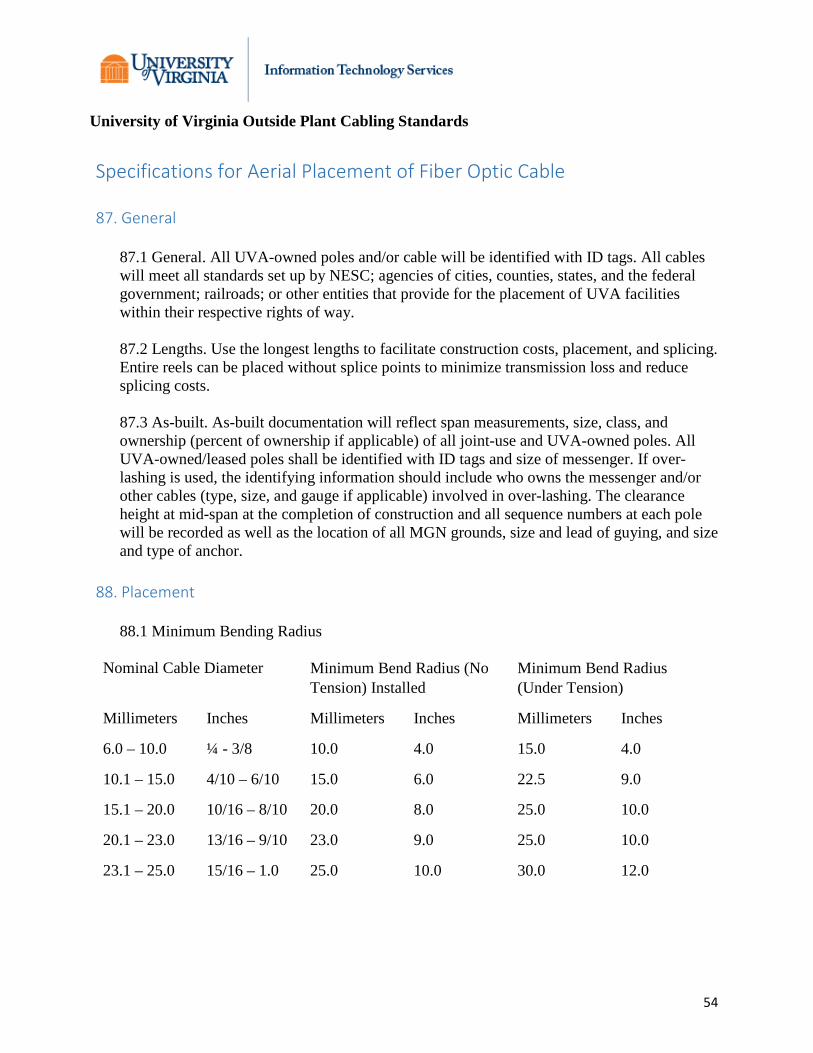
University of Virginia Outside Plant Cabling Standards
54
Specifications for Aerial Placement of Fiber Optic Cable 87. General
87.1 General. All UVA-owned poles and/or cable will be identified with ID tags. All cables will meet all standards set up by NESC; agencies of cities, counties, states, and the federal government; railroads; or other entities that provide for the placement of UVA facilities within their respective rights of way. 87.2 Lengths. Use the longest lengths to facilitate construction costs, placement, and splicing. Entire reels can be placed without splice points to minimize transmission loss and reduce splicing costs. 87.3 As-built. As-built documentation will reflect span measurements, size, class, and ownership (percent of ownership if applicable) of all joint-use and UVA-owned poles. All UVA-owned/leased poles shall be identified with ID tags and size of messenger. If over-lashing is used, the identifying information should include who owns the messenger and/or other cables (type, size, and gauge if applicable) involved in over-lashing. The clearance height at mid-span at the completion of construction and all sequence numbers at each pole will be recorded as well as the location of all MGN grounds, size and lead of guying, and size and type of anchor.
88. Placement
88.1 Minimum Bending Radius Nominal Cable Diameter Minimum Bend Radius (No
Tension) Installed Minimum Bend Radius (Under Tension)
Millimeters Inches Millimeters Inches Millimeters Inches
6.0 – 10.0 ¼ - 3/8 10.0 4.0 15.0 4.0
10.1 – 15.0 4/10 – 6/10 15.0 6.0 22.5 9.0
15.1 – 20.0 10/16 – 8/10 20.0 8.0 25.0 10.0
20.1 – 23.0 13/16 – 9/10 23.0 9.0 25.0 10.0
23.1 – 25.0 15/16 – 1.0 25.0 10.0 30.0 12.0
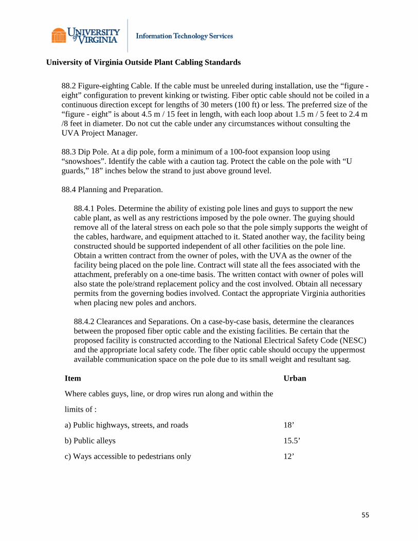
University of Virginia Outside Plant Cabling Standards
55
88.2 Figure-eighting Cable. If the cable must be unreeled during installation, use the “figure - eight” configuration to prevent kinking or twisting. Fiber optic cable should not be coiled in a continuous direction except for lengths of 30 meters (100 ft) or less. The preferred size of the “figure - eight” is about 4.5 m / 15 feet in length, with each loop about 1.5 m / 5 feet to 2.4 m /8 feet in diameter. Do not cut the cable under any circumstances without consulting the UVA Project Manager. 88.3 Dip Pole. At a dip pole, form a minimum of a 100-foot expansion loop using “snowshoes”. Identify the cable with a caution tag. Protect the cable on the pole with “U guards,” 18” inches below the strand to just above ground level. 88.4 Planning and Preparation.
88.4.1 Poles. Determine the ability of existing pole lines and guys to support the new cable plant, as well as any restrictions imposed by the pole owner. The guying should remove all of the lateral stress on each pole so that the pole simply supports the weight of the cables, hardware, and equipment attached to it. Stated another way, the facility being constructed should be supported independent of all other facilities on the pole line. Obtain a written contract from the owner of poles, with the UVA as the owner of the facility being placed on the pole line. Contract will state all the fees associated with the attachment, preferably on a one-time basis. The written contact with owner of poles will also state the pole/strand replacement policy and the cost involved. Obtain all necessary permits from the governing bodies involved. Contact the appropriate Virginia authorities when placing new poles and anchors. 88.4.2 Clearances and Separations. On a case-by-case basis, determine the clearances between the proposed fiber optic cable and the existing facilities. Be certain that the proposed facility is constructed according to the National Electrical Safety Code (NESC) and the appropriate local safety code. The fiber optic cable should occupy the uppermost available communication space on the pole due to its small weight and resultant sag.
Item Urban
Where cables guys, line, or drop wires run along and within the
limits of :
a) Public highways, streets, and roads
b) Public alleys
c) Ways accessible to pedestrians only
18’
15.5’
12’
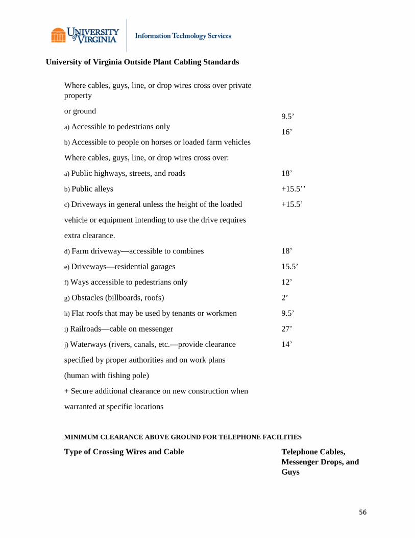
University of Virginia Outside Plant Cabling Standards
56
Where cables, guys, line, or drop wires cross over private property
or ground
a) Accessible to pedestrians only
b) Accessible to people on horses or loaded farm vehicles
9.5’
16’
Where cables, guys, line, or drop wires cross over:
a) Public highways, streets, and roads
b) Public alleys
c) Driveways in general unless the height of the loaded
vehicle or equipment intending to use the drive requires
extra clearance.
d) Farm driveway—accessible to combines
e) Driveways—residential garages
f) Ways accessible to pedestrians only
g) Obstacles (billboards, roofs)
h) Flat roofs that may be used by tenants or workmen
i) Railroads—cable on messenger
j) Waterways (rivers, canals, etc.—provide clearance
specified by proper authorities and on work plans
(human with fishing pole)
+ Secure additional clearance on new construction when
warranted at specific locations
18’
+15.5’’
+15.5’
18’
15.5’
12’
2’
9.5’
27’
14’
MINIMUM CLEARANCE ABOVE GROUND FOR TELEPHONE FACILITIES
Type of Crossing Wires and Cable Telephone Cables, Messenger Drops, and Guys
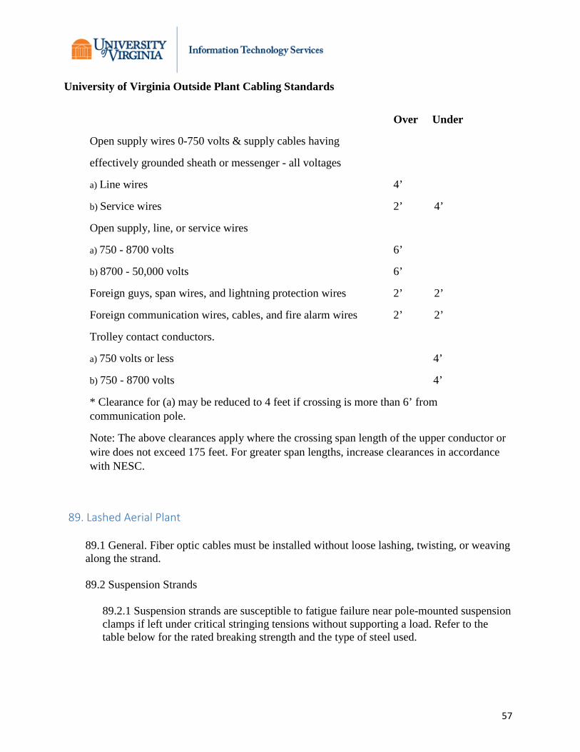
University of Virginia Outside Plant Cabling Standards
57
Over Under
Open supply wires 0-750 volts & supply cables having
effectively grounded sheath or messenger - all voltages
a) Line wires
b) Service wires
4’
2’ 4’
Open supply, line, or service wires
a) 750 - 8700 volts
b) 8700 - 50,000 volts
6’
6’
Foreign guys, span wires, and lightning protection wires 2’ 2’
Foreign communication wires, cables, and fire alarm wires 2’ 2’
Trolley contact conductors.
a) 750 volts or less
b) 750 - 8700 volts
4’
4’
* Clearance for (a) may be reduced to 4 feet if crossing is more than 6’ from communication pole.
Note: The above clearances apply where the crossing span length of the upper conductor or wire does not exceed 175 feet. For greater span lengths, increase clearances in accordance with NESC.
89. Lashed Aerial Plant
89.1 General. Fiber optic cables must be installed without loose lashing, twisting, or weaving along the strand. 89.2 Suspension Strands
89.2.1 Suspension strands are susceptible to fatigue failure near pole-mounted suspension clamps if left under critical stringing tensions without supporting a load. Refer to the table below for the rated breaking strength and the type of steel used.
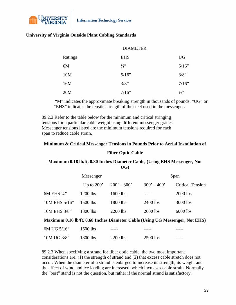
University of Virginia Outside Plant Cabling Standards
58
DIAMETER
Ratings EHS UG
6M ¼” 5/16”
10M 5/16” 3/8”
16M 3/8” 7/16”
20M 7/16” ½”
“M” indicates the approximate breaking strength in thousands of pounds. “UG” or “EHS” indicates the tensile strength of the steel used in the messenger.
89.2.2 Refer to the table below for the minimum and critical stringing tensions for a particular cable weight using different messenger grades. Messenger tensions listed are the minimum tensions required for each span to reduce cable strain.
Minimum & Critical Messenger Tensions in Pounds Prior to Aerial Installation of
Fiber Optic Cable
Maximum 0.18 lb/ft, 0.80 Inches Diameter Cable, (Using EHS Messenger, Not UG)
Messenger Span
Up to 200’ 200’ – 300’ 300’ – 400’ Critical Tension
6M EHS ¼” 1200 lbs 1600 lbs ----- 2000 lbs
10M EHS 5/16” 1500 lbs 1800 lbs 2400 lbs 3000 lbs
16M EHS 3/8” 1800 lbs 2200 lbs 2600 lbs 6000 lbs
Maximum 0.16 lb/ft, 0.68 Inches Diameter Cable (Using UG Messenger, Not EHS)
6M UG 5/16” 1600 lbs ----- ----- -----
10M UG 3/8” 1800 lbs 2200 lbs 2500 lbs -----
89.2.3 When specifying a strand for fiber optic cable, the two most important considerations are: (1) the strength of strand and (2) that excess cable stretch does not occur. When the diameter of a strand is enlarged to increase its strength, its weight and the effect of wind and ice loading are increased, which increases cable strain. Normally the “best” stand is not the question, but rather if the normal strand is satisfactory.
University of Virginia Outside Plant Cabling Standards
59
Technically, the smallest EHS messenger with a satisfactory strength is “best.” When installing a dedicated suspension strand for fiber optic cable, standard hardware (eyebolts, clamps, etc) should be used.
89.3 Overlashing
89.3.1 Considerations
89.3.1.1 Maximum span length (pole spacing) 89.3.1.2 Size of the existing messenger 89.3.1.3 Messenger: EHS or UG 89.3.1.4 Weight and diameter of the existing copper (or fiber) cable(s) 89.3.1.5 Initial messenger tension (If not available, what is the present messenger tension? Measured at what temperature?) 89.3.1.6 Age of the existing copper (or fiber) cables 89.3.1.7 Loading conditions. In the Midwest, only a heavy loading will be considered. 89.3.1.8 Size of the fiber cable being installed (cable, weight, O.D., etc).
89.4 Bonding and Grounding
89.4.1 If dielectric aerial cable is used, maintain the dielectric properties by using non-metallic lashing materials. 89.4.2 If using a metallic messenger or non-dielectric aerial cable on a joint-use pole, or if using a separate pole line forms a continuous bond between all metallic items being placed and the MGN (multi-grounded neutral) used by the power company and/or any other entity occupying the same pole the line uses, then eliminate any different electric potentials between independently owned facilities occupying the same pole line. No communication cable will have less than 4 grounds per mile. A non-dielectric aerial cable must occupy the communication space as defined by the National Electrical Safety Code. A dielectric fiber optic cable may occupy either the supply or the communication space on joint-use construction. No communication cable shall occupy the space between what is defined as the communication and the supply space. Refer to NESC Section 224, par. 4 & 230F. Quoting from NESC Section 235C, E3: “Note that a fully dielectric fiber optic cable carried on a nonmetallic messenger is considered as a supply neutral meeting Rule 230E1 (if located in the supply space) or an ordinary communication cable (if located in
University of Virginia Outside Plant Cabling Standards
60
the communication space). Such cables must be located either in the supply space or the communication space, not in the safety zone between the two spaces.”
89.5 Drip Loop Definition. A “drip loop” is a smooth-curve-type loop form at each pole. The use of the 3” drip loop at each pole is required for two reasons: 1) the extra slack provides for expansion and contraction by the messenger, and 2) it provides extra slack if an object falls on the messenger. Example: Prevents cable damage if a tree falls on the strand. Do not exceed the minimum bending radius of the cable. If contact is likely between the loop and the pole, a cable guard will be required. The cable sequence numbers for each drip loop must be recorded, and the UVA’s cable must be identified with an UVA ownership tag. 89.6 Lashing. Fiber optic cables must be installed without loose lashing, twisting, or weaving along the strand. Contractor will replace any cable showing a deformation. Example: Rippling or kinking. Requirements: Contractor will provide one wrap of lashing wire per linear foot when lashing H-P fiber optic cable to messenger. Cable must be double lashed in 3 different circumstances: 1) over-lashing over existing aerial cables, 2) right-of-way to right-of-way over railroads, and 3) right-of-way to right-of-way over roadways. Cable will be lashed up on a span-by-span basis. All lashing wire should be terminated at each pole with a lashing wire clamp. Lashing wire will be terminated by placing a cable spacer between the fiber optic cable and strand. Locate the lashing wire clamp 2 inches from the strap and spacer. Pull out enough lashing wire for termination on to the lashing wire clamp. Wrap the lashing wire 3 times around only the strand between the lashing wire clamp and the planned location of the first wrap around both the strand and the fiber optic cable. Lashing wire should follow the spiral of the strand wires. 89.7 Splicing and Slack Storage. All cables will be butt-spliced. All slack-cable loops will be placed a minimum of 4 feet from the pole using snowshoes. The minimum cable coil required at a splice location will be from the strand to ground level plus 20 feet on each side of the splice. In no case shall the splicing be done from a bucket. All splicing will be done on the ground in a protected environment (tent, van, or trailer). A minimum of a 100-foot cable coil (placed in snowshoes) will be required in the following circumstances: 1) railroad crossings, 2) highway crossings, 3) Interstate crossings, and 4) main thoroughfares in cities.
University of Virginia Outside Plant Cabling Standards
61
Splicing and Testing 90. General
90.1 This document addresses the University’s requirements for splicing, testing, documenting, and enclosing fiber optic cable for use as part of the University’s Network.
91. Access to Work
91.1 Contractor is required to provide access to all splice locations. 91.2 Access to splice points at all locations other than the freeways can be made from the shoulder of the road. In no case is access from freeways allowed from the shoulder of the road or ramps. No stopping or parking is allowed on the freeway. 91.3 Contractor shall be responsible to repair any damages that it may cause to the right-of-way. 91.4 The cable will be stored in hand-holes at all splice locations. Contractor shall be responsible to access the cable at the splice locations and shall have equipment for removal of loose dirt and water or the removal of other obstructions to the performance of Contractor’s work.
92. Material
92.1 Contractor must be apply to supply material, tools, test equipment, splicing equipment, consumable items, and incidentals necessary to access the cable at the splice locations and perform quality splicing, termination, and testing to include, but not necessarily be limited to, the following:
92.1.1 Enclosure, inner-closure, splice trays, heat shrink sleeves, and encapsulate.
92.1.1.1 The splice closure shall be the Raychem FOSC 450 Fiber Optic Gel Closure or equivalent. 92.1.1.2 Wire tags with clear heat shrink tubing for #6 insulated ground wire such as Panduit #HSDL9-50-31 or approved equal.
92.1.2 #6 green insulated ground wire, mechanical lugs and bolts, nuts and washers for grounding terminations, and cable sheath bonds.
University of Virginia Outside Plant Cabling Standards
62
93. Pre-Placement Cable Testing
93.1 In order to minimize the amount of rework in the right-of-way that may be required and to check for fiber optic cable defects, Contractor shall be responsible for on-reel verification of cable quality prior to placement. 93.2 One hundred percent (100%) of the cable's fiber count shall be tested at 1310 and 1550nm with a Tektronix TFP2 or equivalent Optical Time Domain Reflectometer (OTDR), a stabilized light source, and optical power meter, or equivalent test equipment. Test results will be recorded on a form supplied by the UVA. Completed test forms on each reel shall be delivered to the UVA Project Manager. 93.3 Cable ends shall be sealed upon completion of testing.
94. Ultimate Responsibility
94.1 Contractor shall be ultimately responsible for providing installed fiber cable in which each fiber meets the specifications set forth in this standard.
95. Splices
95.1 All splices shall be placed in hand-holes. There are to be no direct buried splices.
95.1.1 Cable and closure preparation shall conform to the manufacturer's standards and installation manuals. 95.1.2 Hand-holes and pedestals shall be compatible with existing UVA components
95.2 All fibers are to be spliced according to the splice assignment sheets provided by the UVA Project Manager. 95.3 All fibers are to be fusion spliced and placed in a Raychem FOSC 450 Fiber Optic Gel enclosure or equivalent according to the manufactures technical installation instructions and a workmanlike manner. 95.4 All spliced fibers shall be protected by using the appropriate organizer tray and associated incidental items. If fiber optic heat shrink sleeves are used, a heat oven shall be used to shrink all sleeves. Care must be exercised to prevent damage to exposed fibers by overheating. 95.5 To insure acceptable splices prior to closing and encapsulating the splice case, Contractor shall monitor the splicing while it is being performed using an OTDR or a splicer
University of Virginia Outside Plant Cabling Standards
63
with some type of optimizing capability, such as an LID unit or an optimizing alignment screen, or equivalent. 95.6 Splice Grounds
95.6.1 A number six (#6) insulated ground wire shall be installed from the SIP (pedestal) through the existing conduit to the splice enclosure and terminated at both ends. SIP termination nuts shall have a 3/8 inch head. 95.6.2 The ground wire at the SIP shall be identified with major direction associated with the running line of each of the links within a Span, e.g., “West,” on heat-shrink ID tags.
95.7 The UVA Project Manager reserves the right to accept a splice at any time and waive the above requirements on a case-by-case basis as relates to splice loss. A waiver at any time shall not be construed to be a relinquishment of any requirements as spelled out in this specification. 95.8 Contractor must verify that all fibers are compatible end-to-end, i.e., fiber number 24 at location A is fiber number 24 at location Z.
96. Loss Specifications
96.1 The maximum acceptable loss for the cable shall be 0.35 dB/km @ 1310 nm and 0.25 dB/km @ 1550 nm. 96.2 The maximum acceptable loss per splice shall be:
96.2.1 Maximum splice loss in one direction shall be 0.2 dB. 96.2.2 Maximum bi-directional average splice loss shall be 0.2 dB.
96.3 Maintenance splice loss allocation. At acceptance, each fiber Span shall have sufficient reserve loss margin to accept the loss associated with six (6) future maintenance splices and still meet the Span unallocated gain margin.
97. Splicing at Active Locations
97.1 Contractor shall be notified of fibers in the area that are active. It shall be Contractor’s responsibility to coordinate and supervise all work so that there is no interruption of service on these active fibers during cable/closure prep, splicing, testing, etc. at end points.
University of Virginia Outside Plant Cabling Standards
64
97.2 Contractor shall notify the UVA Project Manager at least five (5) working days prior to the commencement of any work at splice points with active fibers. 97.3 Contractor shall have a responsible supervisor monitoring all work being done at all splice locations having active fibers present. 97.4 Unless the UVA Project Manager grants an exception, all splicing on fiber sheaths containing active fibers will be done between the hours of midnight (00:00) and 6:00 AM local. 97.5 Contractor shall have all the materials required to make a temporary and or a permanent repair in the event a fiber is damaged in the course of work. The materials shall be at the site of the work prior to any work beginning. The Contractor shall notify the UVA Project Manager immediately in the event an active fiber is damaged. 97.6 In the event that active fibers are damaged by Contractor, Contractor shall supply all resources necessary and directed by the UVA Project Manager to reestablish service on the active fibers. All costs relating to the damage of the active fibers shall be the responsibility of Contractor.
98. Testing
98.1 All test equipment shall be calibrated within ninety (90) days prior to testing. A sticker with the date of calibration shall be fixed to the equipment. A calibration certificate shall be presented to the UVA Project Manager upon request. 98.2 Each Span shall be tested bi-directionally from end point to end point. Each span trace shall be recorded so that each splice can be clearly expanded (long range, mid range, or high resolution). Some Spans will need all three traces. A Span map shall be filled out recording each splice loss from each direction and the optical length between splices as well as any other information required by the Span map. 98.3 Contractor shall be required to perform the following tests:
98.3.1 Damaged Cable. In the event it is suspected that the cable has been damaged by Contractor at any time, Contractor will be required to test the cable with an OTDR. A hard copy of the OTDR test shall be submitted to the UVA Project Manager. Contractor shall be prepared to test the damaged cable within 24 hours of notification by the UVA Project Manager. 98.3.2 End to End Bi-directional OTDR Span & Splice Test. As directed by the UVA Project Manager, each fiber of each span is to be tested bidirectionally at 1310 nm and/or
University of Virginia Outside Plant Cabling Standards
65
1550 nm from end point to end point and record of results submitted to the UVA for acceptance. 98.3.3 Cable Sheath. The cable sheath of each installed reel of cable shall be tested for continuity and the results recorded on the span map.
99. Acceptance Criteria
99.1 The acceptance criteria shall satisfy, as applicable, the requirements of this standard, which includes:
99.1.1 Verifying, and documenting, that at least a 3 dB unallocated margin of gain exists, at 1310 nm, on each Span. 99.1.2 All as-built drawings
100. Markers
100.1 All splice hand-holes shall be marked with an UVA Cable signs at the top of the post and an UVA splice sign mounted on the post just below the HCP Cable sign.
101. Documentation
101.1 Splice Identification
101.1.1 Link Splices. Splices interconnecting one or more links will be defined by UVA by the characters LS (link splice) and additional identification characters. 101.1.2 Backbone Splices. Splices placed at the end of reels are referred to as backbone splices and numbered by Contractor in sequence for a given Span. 101.1.3 Maintenance Splices. Splices that are required because of a maintenance or repair to the cable are referred to a maintenance splices and shall be identified as MS with additional identification characters, including the date and the time the splice was made.
101.2 Documentation Package
101.2.1 The following hard copy documentation package shall be submitted to the UVA on the applicable forms within five (5) working days after completion of the Span splicing and testing, or a minimum of thirty days prior to the commencement of acceptance testing. Each package shall be neatly organized, with dividers in a separate loose leaf, 3-ring binder or other UVA-approved binder. All forms shall be completely
University of Virginia Outside Plant Cabling Standards
66
filled out. All forms and OTDR shall be legible and reproducible. All sheets/forms shall have a revision log and be titled and dated.
101.2.1.1 A splice identification sheet 101.2.1.2 A span map for each span 101.2.1.3 The splice assignment sheets 101.2.1.4 Reproducible copies of each span trace 101.2.1.5 Reproducible copies of splice traces
University of Virginia Outside Plant Cabling Standards
67
As-built Drawings 102. Introduction
102.1 Delivery Method. Two sets of legible, reproducible as-built drawings on 11 X 17 inch, white paper, in a hard cover binder shall be provided for each Span. The Contractor must also provide a CD or DVD in a format compatible with the University CAD system. 102.2 Symbols and Conventions. The as-built drawings are to use symbols and conventions typically used in telecommunications engineering drawings. The Contractor must provide to the UVA a key to the symbols, icons, model, blocks, etc. that are used in the as-built drawings. 102.3 Consistency. The symbols, conventions, practices, scale, etc., must be consistent from one drawing to the next. 102.4 Governing/Authorization Agency Permits. Where there is a governing agency permit associated with an as-built drawing, Contractor should correlate the method used to show something in one with that used in the other. 102.5 Span As-Built Drawings. A UVA Work Order consists of a set of Spans. Each Span is identified by a name, Contractor’s as-built drawings should use the Span names provided in the Work Order
102.5.1 Each as-built drawing shall use the unique Span name, e.g., “A1 – B1: Hospital Main/Tower – Medical Dental Building,” as part of the title. The Span name should be included in the drawing number, e.g., “A1 – B1: Hospital Main/Tower – Medical Dental Building – 08 of 20.” 102.5.2 Drawing Revisions. As part of the title and status blocks, each drawing shall list the reason(s) that an individual drawing was changed. 102.5.3 The first sheet of a set of Span drawings shall be numbered as page 0. It is a title page and shall contain:
102.5.3.1 Span name/title. 102.5.3.2 A revision table for each of the Span drawings listing the current revision of each drawing. 102.5.3.3 Cable specifications.
University of Virginia Outside Plant Cabling Standards
68
102.5.3.4 To-from information, including start and end point identification such as mile post numbers, highway station numbers, and or other readily recognizable identifiers. 102.5.3.5 A table listing each splice associated with the Span, and, the drawing number containing that splice. 102.5.3.6 A revision record for “A1 – B1: Sparrow Main/Tower – Medical Dental Building.”
102.6 Scale. While no drawings scale is specified, to achieve consistency the typical landscape drawing should have 14 to 15 inches of running line covering about 0.5 miles. Where appropriate, a single 17 x 11 sheet may contain 2 drawings. No specific scale is required for the direction perpendicular to the running line except that it shall be consistent, and reasonable distance differences shall be obvious. Individual drawings may deviate from the above scale requirements for the sake of clarity. 102.7 Span Drawing Order/Sequence. Each set of Span drawings shall read from left to right. That is, when the major direction of the Span is east/west, the left side or edge of a drawing will show the match line for a more westerly/lower numbered drawing. When the major direction of the Span is north/south, the left side or edge of a drawing will show the match line for a more southerly/lower numbered drawing. 102.8 Highway Plan Drawings. If available, VDOT highway plan drawings may be used to add additional information to an as-built drawing.
103. Specific Requirements
103.1 Highway Location Signs/Markers. When available, drawings shall show highway mile post numbers and highway stationing numbers. 103.2 Street, Road, and Highway Identification
103.2.1 The highway marker number, e.g., County E-16, I-80, and so on, will be shown on all county, state, and federal highways that are on a drawing. 103.2.2 Many Virginia counties have assigned names to all county roads that are to be included on the drawings. 103.2.3 Multiple Identifiers: Where there is more than one identifying name and/or number for a street, road, or highway, all identifiers shall be shown on the drawing.
University of Virginia Outside Plant Cabling Standards
69
103.3 County, Township, Range, Section(s). As a minimum, the first and last drawing of a set of Span as-built drawings shall show the county, township name and identifier, and section number(s) peculiar to that particular drawing. When the county or township changes in a Span drawing sequence, the previous and new county, township, and section shall be shown. The city, county, and state boundary symbols shown on the Legend and Symbol sheet should be used. The preference is to have the county, township, and section specified on each drawing. 103.4 Fiber Cable Specifications. The fiber cable specification shall be shown on each page. 103.5 Span Continuity. The first and last page of each set of Span drawings shall show the connections/splices to the connecting Span(s). The connecting Spans shall be shown with their respective Span identification. 103.6 Revision Log. Each drawing shall include a revision table that is used once a drawing has been distributed and or released, whether it is a pre-release, bid issue, as-built, etc. The reason for the change shall be included in the table. 103.7 Splice Identification
103.7.1 Link Splices (LS). Splices interconnecting one or more links within a Span will be identified as “LS” within the splice identifier. 103.7.2 Backbone Splices (B). Splices placed at the end of reels are referred to as backbone splices and will be identified with a “B” within the splice identifier. 103.7.3 Maintenance Splices (MS). Splices that are required because of a maintenance or repair to the cable are referred to a maintenance splices and will be identified with an “MS” within the splice identifier.