University of Huddersfield Repository - Semantic Scholar · Institute of Railway Research,...
50
University of Huddersfield Repository Iwnicki, S., Stichel, S., Orlova, A. and Hecht, M. Dynamics of railway freight vehicles Original Citation Iwnicki, S., Stichel, S., Orlova, A. and Hecht, M. (2015) Dynamics of railway freight vehicles. Vehicle System Dynamics. pp. 1-39. ISSN 0042-3114 This version is available at http://eprints.hud.ac.uk/24585/ The University Repository is a digital collection of the research output of the University, available on Open Access. Copyright and Moral Rights for the items on this site are retained by the individual author and/or other copyright owners. Users may access full items free of charge; copies of full text items generally can be reproduced, displayed or performed and given to third parties in any format or medium for personal research or study, educational or not-for-profit purposes without prior permission or charge, provided: • The authors, title and full bibliographic details is credited in any copy; • A hyperlink and/or URL is included for the original metadata page; and • The content is not changed in any way. For more information, including our policy and submission procedure, please contact the Repository Team at: [email protected]. http://eprints.hud.ac.uk/
Transcript of University of Huddersfield Repository - Semantic Scholar · Institute of Railway Research,...
University of Huddersfield Repository
Iwnicki, S., Stichel, S., Orlova, A. and Hecht, M.
Dynamics of railway freight vehicles
Original Citation
Iwnicki, S., Stichel, S., Orlova, A. and Hecht, M. (2015) Dynamics of railway freight vehicles. Vehicle System Dynamics. pp. 139. ISSN 00423114
This version is available at http://eprints.hud.ac.uk/24585/
The University Repository is a digital collection of the research output of theUniversity, available on Open Access. Copyright and Moral Rights for the itemson this site are retained by the individual author and/or other copyright owners.Users may access full items free of charge; copies of full text items generallycan be reproduced, displayed or performed and given to third parties in anyformat or medium for personal research or study, educational or notforprofitpurposes without prior permission or charge, provided:
• The authors, title and full bibliographic details is credited in any copy;• A hyperlink and/or URL is included for the original metadata page; and• The content is not changed in any way.
For more information, including our policy and submission procedure, pleasecontact the Repository Team at: [email protected].
http://eprints.hud.ac.uk/
DYNAMICSOFRAILWAYFREIGHTVEHICLES
IwnickiS.D.1,StichelS.2,OrlovaA.3,HechtM.4
1. InstituteofRailwayResearch,UniversityofHuddersfield,Huddersfield,UK2. DivisionofRailwayVehicles,KTHRoyalInstituteofTechnology,Stockholm,
Sweden3. PetersburgStateTransportUniversity,St.Petersburg,Russia4. FachgebietSchienenfahrzeugeamInstitutfürLand‐undSeeverkehr,Technische
UniversitätBerlin,Belin,Germany
Keywords:Freightwagon;Vehicledynamics;Computersimulation;RailFreight;RunningGearDesign;FreightBogies
Abstract
Thispapersummarisesthehistoricaldevelopmentofrailwayfreightvehiclesandhowvehicledesignershavetackledthedifficultchallengesofproducingrunninggearwhichcanaccommodatetheveryhightaretoladenmassoftypicalfreightwagonswhilstmaintainingstablerunningatthemaximumrequiredspeedandgoodcurvingperformance.Themostcommoncurrentfreightbogiesaredescribedindetailandrecentimprovementsintechniquesusedtosimulatethedynamicbehaviourofrailwayvehiclesaresummarisedandexamplesofhowthesehavebeenusedtoimprovefreightvehicledynamicbehaviourareincluded.Anumberofrecentdevelopmentsandinnovativecomponentsandsubsystemsareoutlinedandfinallytwonewdevelopmentsarepresentedinmoredetail:theLEILAbogieandtheSUSTRAILbogie.
1 IntroductionFromtheirinceptionrailwayshavebeenpredominantinthecarriageofbulkgoodsandrailwaywagonshavebeendesignedtoallowthistobeeffectedefficientlyondifferenttypesofrailwayinfrastructure.Inmorerecenttimeswithchangesinindustrialneedsandcompetitionfromroadandairtransportrailwayshavecarriedaneverdecliningshareoffreight.Althoughthereissomeevidenceinsomecountriesthatthistrendhasstartedtochangerecentlyduetoroadcongestionthereisstillnotyetawidespreadevidenceofamajormodalshiftfromroadtorailwhichpoliticianshaveindicatedisdesirable.ForexampletheEuropeanTransportWhitepaper2011[1]setsatargetformodalshiftof30%by2030and50%by2050fromroadfreighttoothermodessuchasrailorwaterbornetransportfordistancesover300km.
Thebarrierstothisincreasedmodalshiftfromroadtorailseemtobelargelyduetotherequirementsfrommodernshippersforshorterend‐to‐endtimesbutevenmorethedemandisforhighreliabilityofserviceandforadditionalfeaturessuchastrackingandtracingofshipments,securityandtemperaturecontrol.AsHecht[2]pointsoutthelowerspeedsforrailfreightcomparedwithpassengerservicesarenotmainlyrelatedto
lowervehiclespeedcapabilitybutaremoreduetothefactthatfreighttrainsoftentravelonlowerspeedlinesorareheldforpassengertraffictopassandduetocomplexandlengthyshuntingandhandlingoperationsandmotivepowerandcrewchanges.
Neverthelessiffreightvehiclespeedsandaccelerationandbrakingcapabilitiescouldallowthemtobefullyintegratedwithpassengertrafficthiswouldbringastepchangeinendtoendfreighttrainspeedsaswellasoverallsystemcapacity.Akeyfactorinobtainingthisincreasedspeedistoensurethatthedynamicperformanceoffreightvehiclescanallowsafeandreliableoperationontrackwithdifferentlevelsofirregularitiesandsupportconditions.Runninggearhasevolvedwiththeexperienceofoperationondifferentrailwaysandmorerecentlytheuseofcomputersimulationtoolsandseveralstandardiseddesignsarenowubiquitous.Severalresearchprojectsandteamshaverecentlybeentryingtoadvancefromthispositionusinginnovativedesignsadaptedfrompassengervehiclesorusingothernoveltechniques.Theuseofcomputersimulationsisnowestablishedfordesignofrunninggearandisalsobecomingacceptedaspartofthevehicleacceptanceprocessesinmanycountries.
2 Earlydevelopmentsoffreightwagons
2.1 BackgroundDesignersoffreightvehiclerunninggearfacemanychallengesbutnotleastoftheseisthefactthattheratiooftheladentotaremassofafreightvehiclecanbeasmuchas5:1comparedwithamoremanageable1.5:1fortypicalpassengervehicles.Thiseffectivelymeansthatthesuspensionsystemhastobedesignedfortwodifferentvehicles(andeverystageinbetween).Anumberofcleverdesignshaveevolvedovertheyearsandthemostsuccessfulofthesearenowsummarised.
2.2 UICdoublelinkFreightwagonswithlinktypesuspensionshaveexistedformorethan100years,ascanbeseeninfigure1,andthelinksuspensionisprobablystillthemostcommonsuspensiontypefortwoaxlefreightwagonsinEuropetoday.Asearlyas1890theprincipleofthelinksuspensionwasdefinedasastandard.Areviewoffreightwagonswithlinksuspensioncanbefoundin[3].
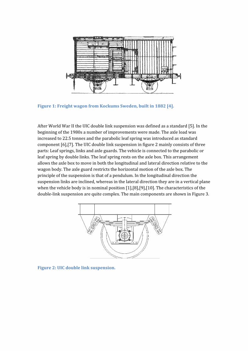
Figure1:FreightwagonfromKockumsSweden,builtin1882[4].
AfterWorldWarIItheUICdoublelinksuspensionwasdefinedasastandard[5].Inthebeginningofthe1980sanumberofimprovementsweremade.Theaxleloadwasincreasedto22.5tonnesandtheparabolicleafspringwasintroducedasstandardcomponent[6],[7].TheUICdoublelinksuspensioninfigure2mainlyconsistsofthreeparts:Leafsprings,linksandaxleguards.Thevehicleisconnectedtotheparabolicorleafspringbydoublelinks.Theleafspringrestsontheaxlebox.Thisarrangementallowstheaxleboxtomoveinboththelongitudinalandlateraldirectionrelativetothewagonbody.Theaxleguardrestrictsthehorizontalmotionoftheaxlebox.Theprincipleofthesuspensionisthatofapendulum.Inthelongitudinaldirectionthesuspensionlinksareinclined,whereasinthelateraldirectiontheyareinaverticalplanewhenthevehiclebodyisinnominalposition[1],[8],[9],[10].Thecharacteristicsofthedouble‐linksuspensionarequitecomplex.ThemaincomponentsareshowninFigure3.
Figure2:UICdoublelinksuspension.
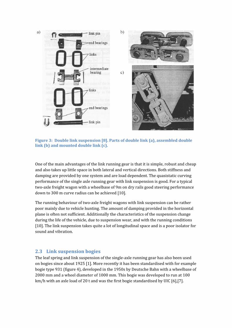
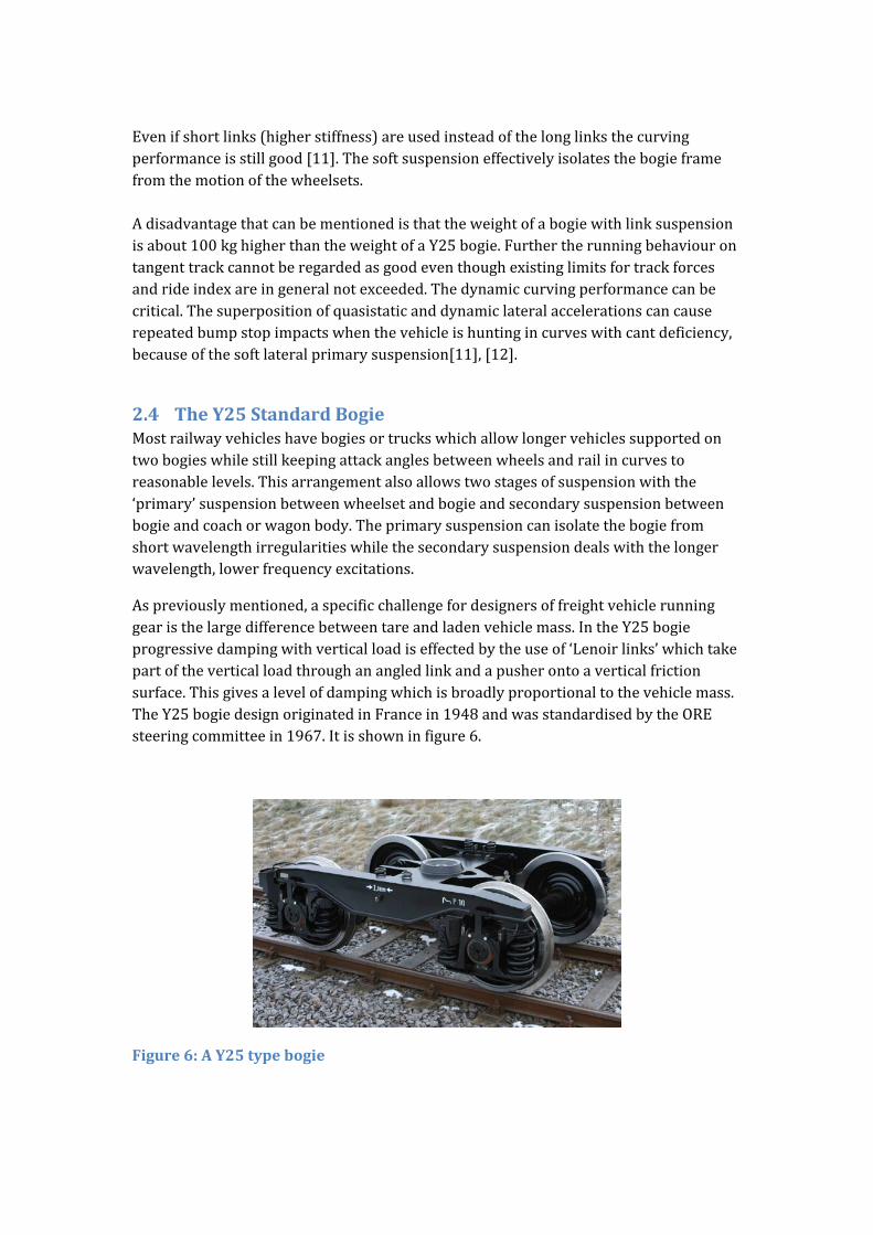
Figure3:Doublelinksuspension[8].Partsofdoublelink(a),assembleddoublelink(b)andmounteddoublelink(c).
Oneofthemainadvantagesofthelinkrunninggearisthatitissimple,robustandcheapandalsotakesuplittlespaceinbothlateralandverticaldirections.Bothstiffnessanddampingareprovidedbyonesystemandareloaddependent.Thequasistaticcurvingperformanceofthesingleaxlerunninggearwithlinksuspensionisgood.Foratypicaltwo‐axlefreightwagonwithawheelbaseof9mondryrailsgoodsteeringperformancedownto300mcurveradiuscanbeachieved[10].
Therunningbehaviouroftwo‐axlefreightwagonswithlinksuspensioncanberatherpoormainlyduetovehiclehunting.Theamountofdampingprovidedinthehorizontalplaneisoftennotsufficient.Additionallythecharacteristicsofthesuspensionchangeduringthelifeofthevehicle,duetosuspensionwear,andwiththerunningconditions[10].Thelinksuspensiontakesquitealotoflongitudinalspaceandisapoorisolatorforsoundandvibration.
2.3 LinksuspensionbogiesTheleafspringandlinksuspensionofthesingle‐axlerunninggearhasalsobeenusedonbogiessinceabout1925[1].Morerecentlyithasbeenstandardisedwithforexamplebogietype931(figure4),developedinthe1950sbyDeutscheBahnwithawheelbaseof2000mmandawheeldiameterof1000mm.Thisbogiewasdevelopedtorunat100km/hwithanaxleloadof20tandwasthefirstbogiestandardisedbyUIC[6],[7].

Figure4:.DBbogieType931[7].
Inthebeginningofthe1980sDBbogietype665wasintroducedwithnewfeatureslikeparabolicleafsprings,22.5tpermissibleaxleloadandshorterlinksasshowninfigure5[7].
Figure5:DBbogieType665[7].
Thebogieframeisaweldedsteeldesignbutinsomeplacesforgedcomponentsareused.Theframeisconnectedtoparabolicortrapezoidalleafsprings,thatrestontheaxlebox,beingconnectedbyswinglinks.Nominallythesuspensionlinksarepositionedinalongitudinalverticalplaneandinclinedinthisplane.Duringvehicleoperationthelinksswinginthatplaneandalsolaterally[1],[6],[7],[11].Asphericalcentre‐pivotandtwosidebearersconnectthebogieframeandthewagonbody.Thesidebearerscanbeeitherrigidorverticallysuspendedandhavethreefunctions:
toactasstaticsupportforthecarbody. toactasrollstiffness. toprovidefrictiondampingbetweencarbodyandbogie
Thequasistaticcurvingperformanceofabogiewithlinksuspensionisgenerallyverygooddueto:
theshortwheelsetdistanceinthebogieof1.8m. thesoftlongitudinalprimarysuspension.
Evenifshortlinks(higherstiffness)areusedinsteadofthelonglinksthecurvingperformanceisstillgood[11].Thesoftsuspensioneffectivelyisolatesthebogieframefromthemotionofthewheelsets.Adisadvantagethatcanbementionedisthattheweightofabogiewithlinksuspensionisabout100kghigherthantheweightofaY25bogie.Furthertherunningbehaviourontangenttrackcannotberegardedasgoodeventhoughexistinglimitsfortrackforcesandrideindexareingeneralnotexceeded.Thedynamiccurvingperformancecanbecritical.Thesuperpositionofquasistaticanddynamiclateralaccelerationscancauserepeatedbumpstopimpactswhenthevehicleishuntingincurveswithcantdeficiency,becauseofthesoftlateralprimarysuspension[11],[12].
2.4 TheY25StandardBogieMostrailwayvehicleshavebogiesortruckswhichallowlongervehiclessupportedontwobogieswhilestillkeepingattackanglesbetweenwheelsandrailincurvestoreasonablelevels.Thisarrangementalsoallowstwostagesofsuspensionwiththe‘primary’suspensionbetweenwheelsetandbogieandsecondarysuspensionbetweenbogieandcoachorwagonbody.Theprimarysuspensioncanisolatethebogiefromshortwavelengthirregularitieswhilethesecondarysuspensiondealswiththelongerwavelength,lowerfrequencyexcitations.
Aspreviouslymentioned,aspecificchallengefordesignersoffreightvehiclerunninggearisthelargedifferencebetweentareandladenvehiclemass.IntheY25bogieprogressivedampingwithverticalloadiseffectedbytheuseof‘Lenoirlinks’whichtakepartoftheverticalloadthroughanangledlinkandapusherontoaverticalfrictionsurface.Thisgivesalevelofdampingwhichisbroadlyproportionaltothevehiclemass.TheY25bogiedesignoriginatedinFrancein1948andwasstandardisedbytheOREsteeringcommitteein1967.Itisshowninfigure6.
Figure6:AY25typebogie
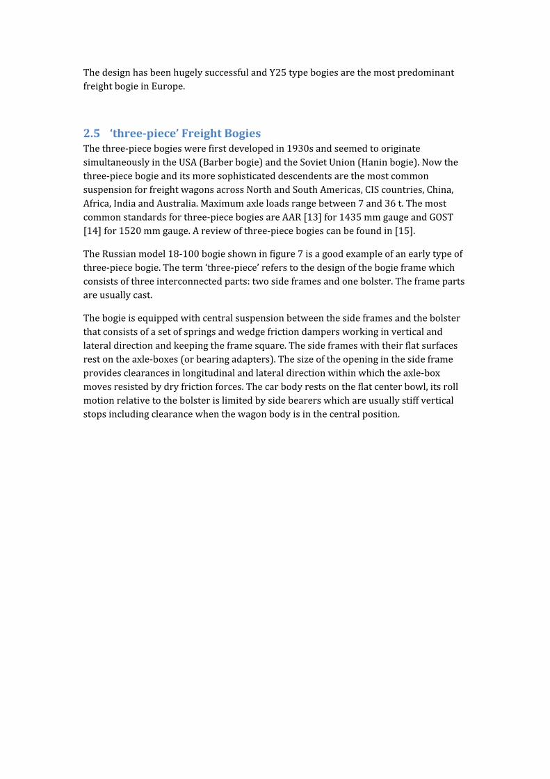
ThedesignhasbeenhugelysuccessfulandY25typebogiesarethemostpredominantfreightbogieinEurope.
2.5 ‘three‐piece’FreightBogiesThethree‐piecebogieswerefirstdevelopedin1930sandseemedtooriginatesimultaneouslyintheUSA(Barberbogie)andtheSovietUnion(Haninbogie).Nowthethree‐piecebogieanditsmoresophisticateddescendentsarethemostcommonsuspensionforfreightwagonsacrossNorthandSouthAmericas,CIScountries,China,Africa,IndiaandAustralia.Maximumaxleloadsrangebetween7and36t.Themostcommonstandardsforthree‐piecebogiesareAAR[13]for1435mmgaugeandGOST[14]for1520mmgauge.Areviewofthree‐piecebogiescanbefoundin[15].
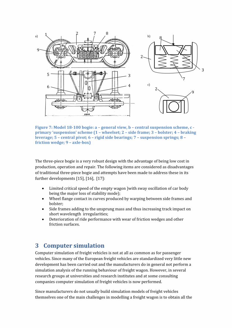
TheRussianmodel18‐100bogieshowninfigure7isagoodexampleofanearlytypeofthree‐piecebogie.Theterm‘three‐piece’referstothedesignofthebogieframewhichconsistsofthreeinterconnectedparts:twosideframesandonebolster.Theframepartsareusuallycast.
Thebogieisequippedwithcentralsuspensionbetweenthesideframesandthebolsterthatconsistsofasetofspringsandwedgefrictiondampersworkinginverticalandlateraldirectionandkeepingtheframesquare.Thesideframeswiththeirflatsurfacesrestontheaxle‐boxes(orbearingadapters).Thesizeoftheopeninginthesideframeprovidesclearancesinlongitudinalandlateraldirectionwithinwhichtheaxle‐boxmovesresistedbydryfrictionforces.Thecarbodyrestsontheflatcenterbowl,itsrollmotionrelativetothebolsterislimitedbysidebearerswhichareusuallystiffverticalstopsincludingclearancewhenthewagonbodyisinthecentralposition.
a) b)
c)
Figure7:Model18‐100bogie:a–generalview,b–centralsuspensionscheme,c‐primary‘suspension’scheme(1–wheelset;2–sideframe;3–bolster;4–brakingleverage;5–centralpivot;6–rigidsidebearings;7–suspensionsprings;8–frictionwedge;9–axle‐box)
Thethree‐piecebogieisaveryrobustdesignwiththeadvantageofbeinglowcostinproduction,operationandrepair.Thefollowingitemsareconsideredasdisadvantagesoftraditionalthree‐piecebogieandattemptshavebeenmadetoaddresstheseinitsfurtherdevelopments[15],[16],[17]:
Limitedcriticalspeedoftheemptywagon)withswayoscillationofcarbodybeingthemajorlossofstabilitymode);
Wheelflangecontactincurvesproducedbywarpingbetweensideframesandbolster;
Sideframesaddingtotheunsprungmassandthusincreasingtrackimpactonshortwavelengthirregularities;
Deteriorationofrideperformancewithwearoffrictionwedgesandotherfrictionsurfaces.
3 ComputersimulationComputersimulationoffreightvehiclesisnotatallascommonasforpassengervehicles.SincemanyoftheEuropeanfreightvehiclesarestandardizedverylittlenewdevelopmenthasbeencarriedoutandthemanufacturersdoingeneralnotperformasimulationanalysisoftherunningbehaviouroffreightwagon.However,inseveralresearchgroupsatuniversitiesandresearchinstitutesandatsomeconsultingcompaniescomputersimulationoffreightvehiclesisnowperformed.
Sincemanufacturersdonotusuallybuildsimulationmodelsoffreightvehiclesthemselvesoneofthemainchallengesinmodellingafreightwagonistoobtainallthe
7
2
3
8
29
1
3
4
5
6
72 8
9
inputparametersrequired.Anotheraspectisthatmostsuspensionelementsarestronglynon‐linearandinmanycasesevenmathematicallynon‐smooth.Thismakesitverydifficulttobuildupsimulationmodelsthatprovidegoodresultscomparedtomeasurementresults.Someofthephenomenaobservedduringsimulationoffreightvehicleswillbediscussedbelow.
Further,asdescribedinSection3.1,thecharacteristicsofthesuspensionelementscanvaryduringoperationduetowearorenvironmentaleffectssuchasforexamplesurfacecontaminationchangingthefrictioncoefficientinslidingsurfaces.
Themainpurposeofsimulationstudiesoffreightvehiclesisveryoftenastabilityanalysis(seeSection3.2)oraninvestigationofthecurvingbehaviourofthefreightwagon(seeSection3.3).Sincetheaxleloadsoffreightwagonsareusuallyhigh,theinvestigationofwheelorrailwearandrollingcontactfatigueisoftentheprimaryreasonforasimulationstudyincurves.
3.1 SuspensioncomponentsThesuspensioninmostfreightvehiclesreliesonfrictiondamping.Frictionelementsarelowcost,requirelittlemaintenanceandareusuallyloaddependent.Thismeansthattheleveloffrictiondampingchangeswithaxleload,animportantfeatureinfreightwagonsduetothehightaretoladenratioalreadymentioned.Surveysofmodellingoffrictioncomponentsinfreightwagoncanbefoundforexamplein[18]‐[22].Papers[18]and[19]aregeneralreviewsofrailvehiclesuspensioncomponents,while[20]isfocusedonfreightvehiclesandalsodiscussesissuessuchasstabilityandcurvingoffreightvehicles.Papers[21]and[22]arefocussedonmodellingfrictionwedgesofthree‐piecebogies.AlsointheproceedingsfromtheEuromech500colloquium[23]manyvaluablecontributionsonthetopicofnon‐smoothsuspensionelementscanbefound.Variousarrangementsofsuspensionelementstosimulatevehiclesuspensionsaredocumentedin[24],[25].
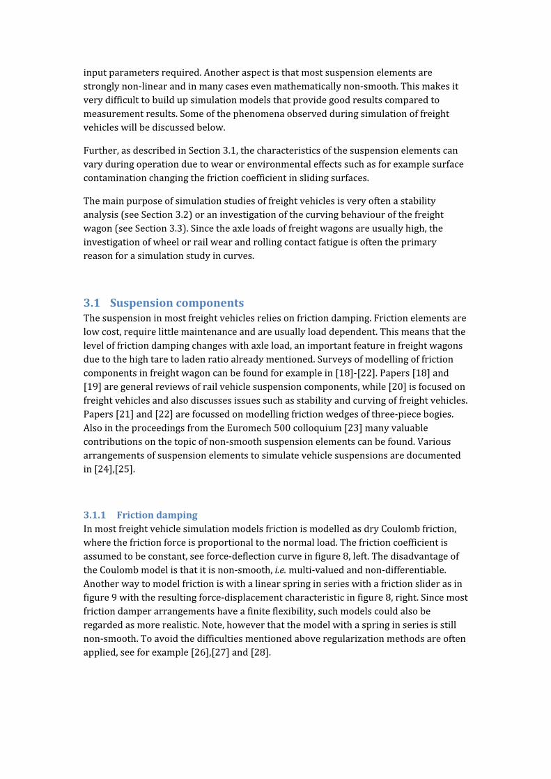
3.1.1 FrictiondampingInmostfreightvehiclesimulationmodelsfrictionismodelledasdryCoulombfriction,wherethefrictionforceisproportionaltothenormalload.Thefrictioncoefficientisassumedtobeconstant,seeforce‐deflectioncurveinfigure8,left.ThedisadvantageoftheCoulombmodelisthatitisnon‐smooth,i.e.multi‐valuedandnon‐differentiable.Anotherwaytomodelfrictioniswithalinearspringinserieswithafrictionsliderasinfigure9withtheresultingforce‐displacementcharacteristicinfigure8,right.Sincemostfrictiondamperarrangementshaveafiniteflexibility,suchmodelscouldalsoberegardedasmorerealistic.Note,howeverthatthemodelwithaspringinseriesisstillnon‐smooth.Toavoidthedifficultiesmentionedaboveregularizationmethodsareoftenapplied,seeforexample[26],[27]and[28].
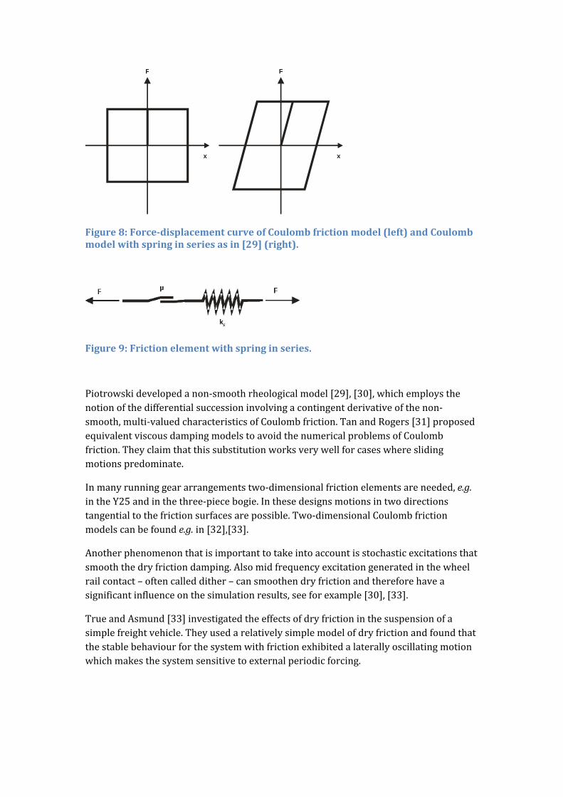
Figure8:Force‐displacementcurveofCoulombfrictionmodel(left)andCoulombmodelwithspringinseriesasin[29](right).
Figure9:Frictionelementwithspringinseries.
Piotrowskidevelopedanon‐smoothrheologicalmodel[29],[30],whichemploysthenotionofthedifferentialsuccessioninvolvingacontingentderivativeofthenon‐smooth,multi‐valuedcharacteristicsofCoulombfriction.TanandRogers[31]proposedequivalentviscousdampingmodelstoavoidthenumericalproblemsofCoulombfriction.Theyclaimthatthissubstitutionworksverywellforcaseswhereslidingmotionspredominate.
Inmanyrunninggeararrangementstwo‐dimensionalfrictionelementsareneeded,e.g.intheY25andinthethree‐piecebogie.Inthesedesignsmotionsintwodirectionstangentialtothefrictionsurfacesarepossible.Two‐dimensionalCoulombfrictionmodelscanbefounde.g.in[32],[33].
Anotherphenomenonthatisimportanttotakeintoaccountisstochasticexcitationsthatsmooththedryfrictiondamping.Alsomidfrequencyexcitationgeneratedinthewheelrailcontact–oftencalleddither–cansmoothendryfrictionandthereforehaveasignificantinfluenceonthesimulationresults,seeforexample[30],[33].
TrueandAsmund[33]investigatedtheeffectsofdryfrictioninthesuspensionofasimplefreightvehicle.Theyusedarelativelysimplemodelofdryfrictionandfoundthatthestablebehaviourforthesystemwithfrictionexhibitedalaterallyoscillatingmotionwhichmakesthesystemsensitivetoexternalperiodicforcing.
x
F
x
F
3.1.2 Wagonswithlinksuspension
3.1.2.1 Basicmodelofleafspringandlinksuspension
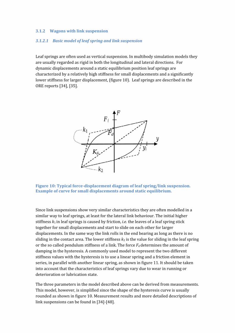
Leafspringsareoftenusedasverticalsuspension.Inmultibodysimulationmodelstheyareusuallyregardedasrigidinboththelongitudinalandlateraldirections.Fordynamicdisplacementsaroundastaticequilibriumpositionleafspringsarecharacterizedbyarelativelyhighstiffnessforsmalldisplacementsandasignificantlylowerstiffnessforlargerdisplacement,(figure10).LeafspringsaredescribedintheOREreports[34],[35].
Figure10:Typicalforce‐displacementdiagramofleafspring/linksuspension.Exampleofcurveforsmalldisplacementsaroundstaticequilibrium.
Sincelinksuspensionsshowverysimilarcharacteristicstheyareoftenmodelledinasimilarwaytoleafsprings,atleastforthelaterallinkbehaviour.Theinitialhigherstiffnessk1inleafspringsiscausedbyfriction,i.e.theleavesofaleafspringsticktogetherforsmalldisplacementsandstarttoslideoneachotherforlargerdisplacements.Inthesamewaythelinkrollsintheendbearingaslongasthereisnoslidinginthecontactarea.Thelowerstiffnessk2isthevalueforslidingintheleafspringorthesocalledpendulumstiffnessofalink.TheforceFddeterminestheamountofdampinginthehysteresis.Acommonlyusedmodeltorepresentthetwodifferentstiffnessvalueswiththehysteresisistousealinearspringandafrictionelementinseries,inparallelwithanotherlinearspring,asshowninfigure11.Itshouldbetakenintoaccountthatthecharacteristicsofleafspringsvaryduetowearinrunningordeteriorationorlubricationstate.
Thethreeparametersinthemodeldescribedabovecanbederivedfrommeasurements.Thismodel,however,issimplifiedsincetheshapeofthehysteresiscurveisusuallyroundedasshowninfigure10.Measurementresultsandmoredetaileddescriptionsoflinksuspensionscanbefoundin[34]‐[48].
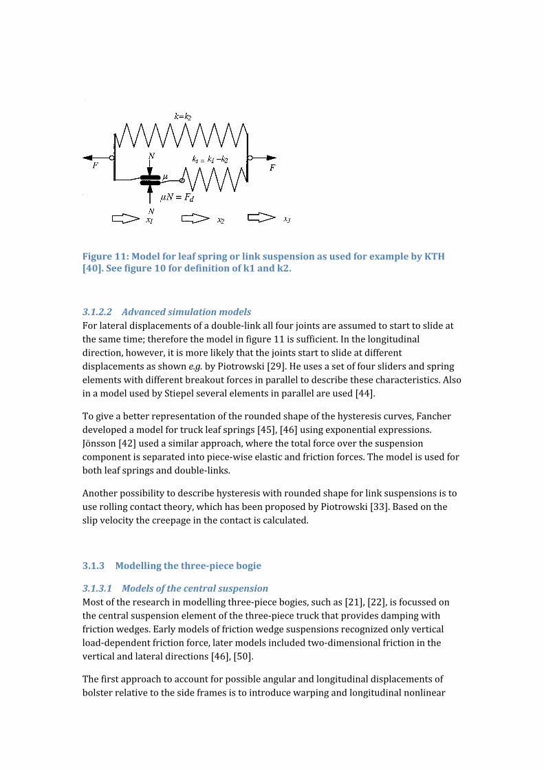
Figure11:ModelforleafspringorlinksuspensionasusedforexamplebyKTH[40].Seefigure10fordefinitionofk1andk2.
3.1.2.2 AdvancedsimulationmodelsForlateraldisplacementsofadouble‐linkallfourjointsareassumedtostarttoslideatthesametime;thereforethemodelinfigure11issufficient.Inthelongitudinaldirection,however,itismorelikelythatthejointsstarttoslideatdifferentdisplacementsasshowne.g.byPiotrowski[29].Heusesasetoffourslidersandspringelementswithdifferentbreakoutforcesinparalleltodescribethesecharacteristics.AlsoinamodelusedbyStiepelseveralelementsinparallelareused[44].
Togiveabetterrepresentationoftheroundedshapeofthehysteresiscurves,Fancherdevelopedamodelfortruckleafsprings[45],[46]usingexponentialexpressions.Jönsson[42]usedasimilarapproach,wherethetotalforceoverthesuspensioncomponentisseparatedintopiece‐wiseelasticandfrictionforces.Themodelisusedforbothleafspringsanddouble‐links.
Anotherpossibilitytodescribehysteresiswithroundedshapeforlinksuspensionsistouserollingcontacttheory,whichhasbeenproposedbyPiotrowski[33].Basedontheslipvelocitythecreepageinthecontactiscalculated.
3.1.3 Modellingthethree‐piecebogie
3.1.3.1 ModelsofthecentralsuspensionMostoftheresearchinmodellingthree‐piecebogies,suchas[21],[22],isfocussedonthecentralsuspensionelementofthethree‐piecetruckthatprovidesdampingwithfrictionwedges.Earlymodelsoffrictionwedgesuspensionsrecognizedonlyverticalload‐dependentfrictionforce,latermodelsincludedtwo‐dimensionalfrictionintheverticalandlateraldirections[46],[50].
Thefirstapproachtoaccountforpossibleangularandlongitudinaldisplacementsofbolsterrelativetothesideframesistointroducewarpingandlongitudinalnonlinear
resistancecharacteristicsintothemodel,asitisdonein[15],[17].Insuchcasethewedgesarenotmodelledasseparatebodies,buttheequivalentforceagainstdisplacementcharacteristicsareintroducedaccountingforwedgeparameters,suchasinclinationangle,widthoftheverticalsurface,widthoftheinclinedsurface,frictioncoefficientsoninclinedandverticalsurfaces,etc.
Thesecondapproachtoaccountforallpossibledegreesoffreedombetweensideframeandbolsteristointroducemultiplecontactpointsmappedalongtheedgesofthewedgewithtwo‐dimensionalfrictionforceelementsineachofthem.SuchanapproachwasusedbyBallewetal[46],itisimplementedinsimulationtoolssuchasVAMPIRE[52],andtheUniversalMechanismsoftware[52].Numerouscontactelementsrequireanefficientnumericalsimulationalgorithmtobeimplementedintothesoftwarethatprovidesfastsolutiontoresultingstiffsystemofequations,suchastheonedevelopedbyPogorelov[57].Thewedgesaretreatedasmassless.Contacttypemodelsallowthestudyofsuchcomplicatedphenomenonasunevendistributionofcontactforcesoverthewedgesurfaces,implementationofresilientpadsonwedgesurfaces,jammingandwedging[54].Inpaper[56]theauthorsincludedthemassofthewedgeintoconsiderationtostudyitsdynamicproperties.
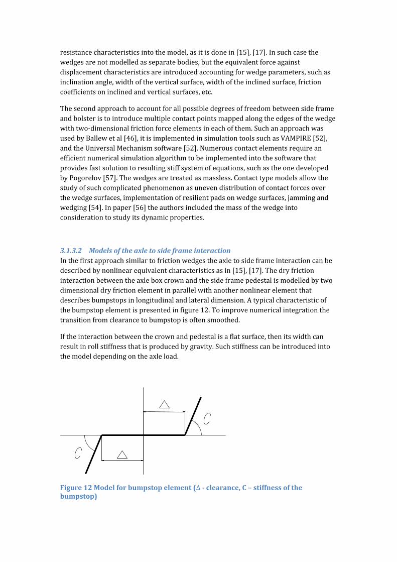
3.1.3.2 ModelsoftheaxletosideframeinteractionInthefirstapproachsimilartofrictionwedgestheaxletosideframeinteractioncanbedescribedbynonlinearequivalentcharacteristicsasin[15],[17].Thedryfrictioninteractionbetweentheaxleboxcrownandthesideframepedestalismodelledbytwodimensionaldryfrictionelementinparallelwithanothernonlinearelementthatdescribesbumpstopsinlongitudinalandlateraldimension.Atypicalcharacteristicofthebumpstopelementispresentedinfigure12.Toimprovenumericalintegrationthetransitionfromclearancetobumpstopisoftensmoothed.
Iftheinteractionbetweenthecrownandpedestalisaflatsurface,thenitswidthcanresultinrollstiffnessthatisproducedbygravity.Suchstiffnesscanbeintroducedintothemodeldependingontheaxleload.
Figure12Modelforbumpstopelement(∆‐clearance, –stiffnessofthebumpstop)
Thesecondapproachistointroducemultiplecontactpointsontheedgesofthecrownwithtwo‐dimensionalfrictionelementsinthem.Thebumpstopsarethenalsothecontactelementsbetweentheaxleboxoradapterandthestopsinthesideframejaws.Suchapproachisusedin[57]aswellasinUniversalMechanismsoftware[52].
3.1.3.3 ModelsofthecentrebowlandsidebearersThesameapproachescanbeappliedtomodelsofthecentrebowltocentreplateinteractionandatthesidebearers.
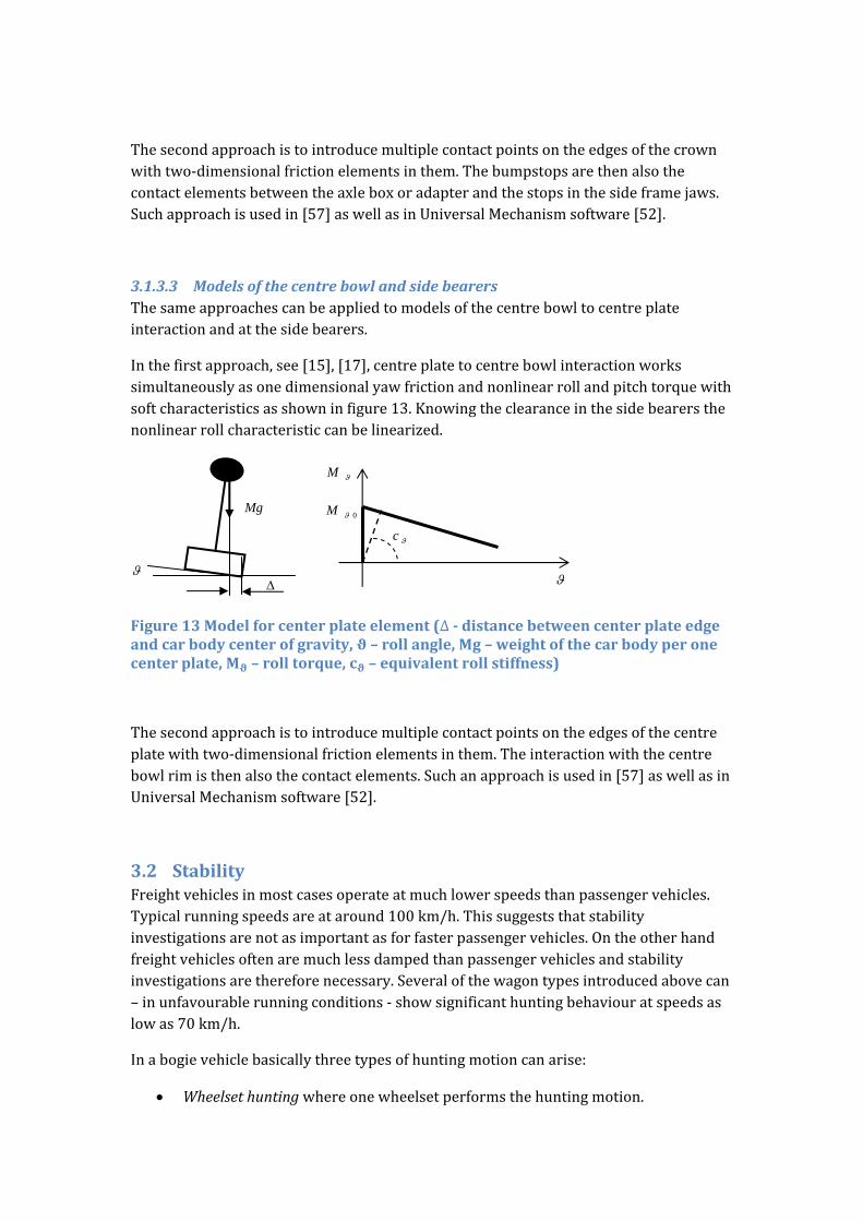
Inthefirstapproach,see[15],[17],centreplatetocentrebowlinteractionworkssimultaneouslyasonedimensionalyawfrictionandnonlinearrollandpitchtorquewithsoftcharacteristicsasshowninfigure13.Knowingtheclearanceinthesidebearersthenonlinearrollcharacteristiccanbelinearized.
Figure13Modelforcenterplateelement(∆‐distancebetweencenterplateedgeandcarbodycenterofgravity, –rollangle, –weightofthecarbodyperonecenterplate, –rolltorque, –equivalentrollstiffness)
Thesecondapproachistointroducemultiplecontactpointsontheedgesofthecentreplatewithtwo‐dimensionalfrictionelementsinthem.Theinteractionwiththecentrebowlrimisthenalsothecontactelements.Suchanapproachisusedin[57]aswellasinUniversalMechanismsoftware[52].
3.2 StabilityFreightvehiclesinmostcasesoperateatmuchlowerspeedsthanpassengervehicles.Typicalrunningspeedsareataround100km/h.Thissuggeststhatstabilityinvestigationsarenotasimportantasforfasterpassengervehicles.Ontheotherhandfreightvehiclesoftenaremuchlessdampedthanpassengervehiclesandstabilityinvestigationsarethereforenecessary.Severalofthewagontypesintroducedabovecan–inunfavourablerunningconditions‐showsignificanthuntingbehaviouratspeedsaslowas70km/h.
Inabogievehiclebasicallythreetypesofhuntingmotioncanarise:
Wheelsethuntingwhereonewheelsetperformsthehuntingmotion.
M
0M
c
Mg

Bogiehuntingwhereawholebogieistakingoverthehuntingmotion. Carbodyhuntingwherethecarbodyperformsayawmotionandthetwobogies
mainlyfollowthecarbodywithlateralmotions,i.e.thewholevehicletakesoverthehuntingmotion.
Carbodyhuntingisoftenatypeofresonancephenomenon,wheretheKlingelhuntingfrequencygivenmainlybyvehiclespeedandconicityinthecontactcoincideswiththeyaweigenfrequencyofthecarbody.
Huntingmotionwithanon‐zerolimitcycledependsonthewheel‐railgeometry,thesuspensionandthemassesandinertiasofthevehicle.Sincethemassandinertia,andinmostcasesthesuspensionstiffnessanddampingofthefreightwagonwillsignificantlychangewithload,thetypeofhuntingmotionobservedusuallydiffersbetweenanemptyandaloadedwagon.Sincethestiffnessvaluesbetweenaxleboxandbogieframe(inabogievehicle)arelowerinanunloadedvehicle,theriskforwheelsetorbogiehuntingishigher.Inloadedvehicles,vehiclehuntingcanoftenbeobserved.Sincethefrequencyofwheelsethuntingisusuallylow(typicallybetween1and2Hz)thewheelrailforcesinducedarerelativelylowandinmostcasesbelowthelimitvaluesstipulatedinstandards.Therefore,thevehicledesigninrealityallowsforthecarbodyinstabilitytohappeninsomeconditions.Otherwisethesuspensionneedstobesostiffthatthecurvingperformancewouldsuffer,andtheamountofwearandRCFwouldincreasesignificantly.Theriskofcarbodyhuntingcanvarywiththetypeofloadsincethiscaninfluencetheyaweigenfrequencyofthecarbody.
Duetothesignificantinherentnon‐linearityandnon‐smoothnessofthesuspensionelementslinearizationofthemodelsisusuallynotrealistic.Itisthereforenecessarytoperformtimesteppigintegrationwiththefullnon‐linearmodel.Thetaskisingeneraltofindthenon‐linearcriticalspeedvBofthewagonascanbeseeninthegenericbifurcationdiagraminfigure14.
Figure14:Genericbifurcationdiagram
Incomplexmodelsitisverydifficulttofindtheexactcriticalspeed,forexamplewithapathfollowingmethod[58].Thereforeotherengineeringmethodsareused.Onepossibilitythathasbeensuggestede.g.byPolach[59]istoexcitethevehiclewithaninitialdisturbancethatcaneitherbedeterministicorstochastic.Aftertheinitialdisturbancethevehicleisrunonidealsmoothtrack.Iftheoscillationvanishesthevehicleisregardedasstable.Thesimulationshavetoberepeatedwithincreasingspeeduntiltheoscillationsdonotdisappear.Inthatcasethenon‐linearcriticalspeedvb(figure15)isreached.Ariskwiththismethodisthattheinitialdisturbanceisnothighenoughtoinitiatealimitcycleoscillationandthatthecriticalspeeddetectedishigherthantherealnon‐linearcriticalspeed.
Anothermethodtodetectthenon‐linearcriticalspeedisstartthesimulationsataveryhighspeedtobesurethatthevehiclehasreachedthenon‐zeroattractor(limitcycle).Thenthespeediscontinuouslyreduceduntilthelimitcyclebehaviourdisappears.Polachalsodescribesthismethod.IthasbeenusedforexamplebyBoronenkoetal[15]totunethesuspensionofthree‐piecebogies.
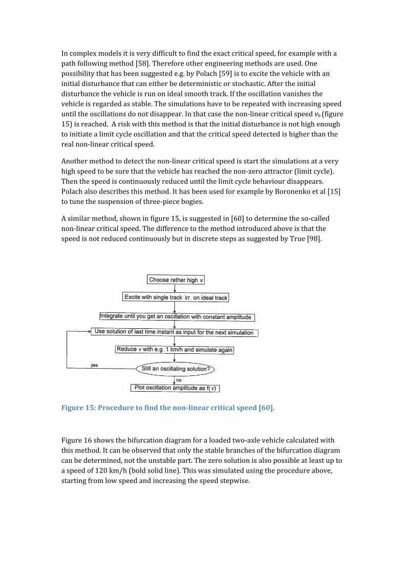
Asimilarmethod,showninfigure15,issuggestedin[60]todeterminetheso‐callednon‐linearcriticalspeed.ThedifferencetothemethodintroducedaboveisthatthespeedisnotreducedcontinuouslybutindiscretestepsassuggestedbyTrue[98].
Figure15:Proceduretofindthenon‐linearcriticalspeed[60].
Figure16showsthebifurcationdiagramforaloadedtwo‐axlevehiclecalculatedwiththismethod.Itcanbeobservedthatonlythestablebranchesofthebifurcationdiagramcanbedetermined,nottheunstablepart.Thezerosolutionisalsopossibleatleastuptoaspeedof120km/h(boldsolidline).Thiswassimulatedusingtheprocedureabove,startingfromlowspeedandincreasingthespeedstepwise.

Figure16:Bifurcationdiagramforaloadedtwo‐axlevehiclewithlinksuspension(21taxleload)Wheel:somewhatwornS1002.Rail:NominalUIC60[42].
Hoffmanalsoinvestigatedthestabilityofatwo‐axlewagonwithlinksuspension[43],[61].HeusesthelinkmodeldevelopedbyPiotrowski[29].TheleafspringsmodelisbasedonFancheretal[46].Figure17.showsattractorsfortwodifferenttypesoffreightwagons.Theresultsareinprinciplequitesimilartothoseinfigure16.
Figure17:AttractorsfortheHbbills311andtheG69freightwagons.ThemodelwiththemeasuredcharacteristicsoftheUIClinksisdampinglessthanthemodelwiththecylindricalcharacteristics.Thehuntingattractorexistsevenforlowspeeds[61].
Gialleonardoetal[62]extendedthistypeofstabilityanalysisforatwo‐axlewagonwithlinksuspensiononcurvedtrack.Ascanbeseeninfigure18.theleadingwheelset(ylw)
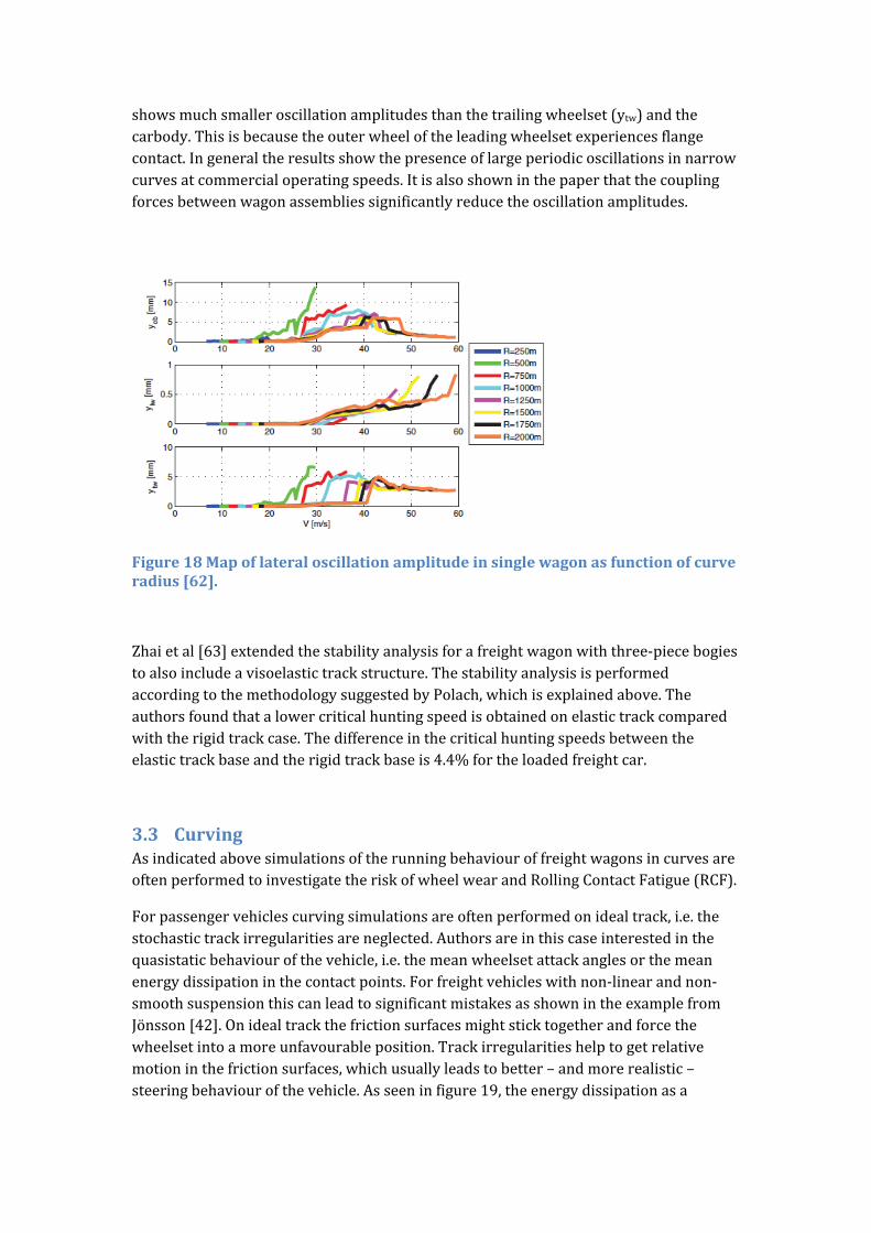
showsmuchsmalleroscillationamplitudesthanthetrailingwheelset(ytw)andthecarbody.Thisisbecausetheouterwheeloftheleadingwheelsetexperiencesflangecontact.Ingeneraltheresultsshowthepresenceoflargeperiodicoscillationsinnarrowcurvesatcommercialoperatingspeeds.Itisalsoshowninthepaperthatthecouplingforcesbetweenwagonassembliessignificantlyreducetheoscillationamplitudes.
Figure18Mapoflateraloscillationamplitudeinsinglewagonasfunctionofcurveradius[62].
Zhaietal[63]extendedthestabilityanalysisforafreightwagonwiththree‐piecebogiestoalsoincludeavisoelastictrackstructure.ThestabilityanalysisisperformedaccordingtothemethodologysuggestedbyPolach,whichisexplainedabove.Theauthorsfoundthatalowercriticalhuntingspeedisobtainedonelastictrackcomparedwiththerigidtrackcase.Thedifferenceinthecriticalhuntingspeedsbetweentheelastictrackbaseandtherigidtrackbaseis4.4%fortheloadedfreightcar.
3.3 CurvingAsindicatedabovesimulationsoftherunningbehaviouroffreightwagonsincurvesareoftenperformedtoinvestigatetheriskofwheelwearandRollingContactFatigue(RCF).
Forpassengervehiclescurvingsimulationsareoftenperformedonidealtrack,i.e.thestochastictrackirregularitiesareneglected.Authorsareinthiscaseinterestedinthequasistaticbehaviourofthevehicle,i.e.themeanwheelsetattackanglesorthemeanenergydissipationinthecontactpoints.Forfreightvehicleswithnon‐linearandnon‐smoothsuspensionthiscanleadtosignificantmistakesasshownintheexamplefromJönsson[42].Onidealtrackthefrictionsurfacesmightsticktogetherandforcethewheelsetintoamoreunfavourableposition.Trackirregularitieshelptogetrelativemotioninthefrictionsurfaces,whichusuallyleadstobetter–andmorerealistic–steeringbehaviourofthevehicle.Asseeninfigure19,theenergydissipationasa
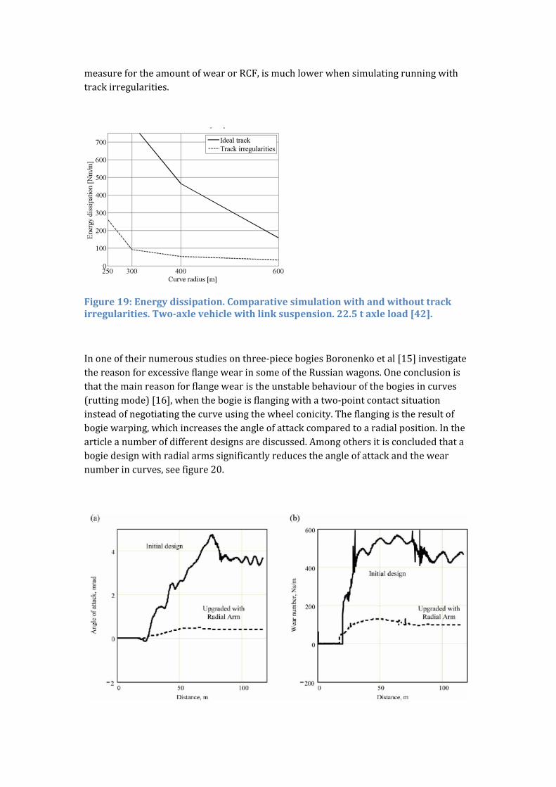
measurefortheamountofwearorRCF,ismuchlowerwhensimulatingrunningwithtrackirregularities.
Figure19:Energydissipation.Comparativesimulationwithandwithouttrackirregularities.Two‐axlevehiclewithlinksuspension.22.5taxleload[42].
Inoneoftheirnumerousstudiesonthree‐piecebogiesBoronenkoetal[15]investigatethereasonforexcessiveflangewearinsomeoftheRussianwagons.Oneconclusionisthatthemainreasonforflangewearistheunstablebehaviourofthebogiesincurves(ruttingmode)[16],whenthebogieisflangingwithatwo‐pointcontactsituationinsteadofnegotiatingthecurveusingthewheelconicity.Theflangingistheresultofbogiewarping,whichincreasestheangleofattackcomparedtoaradialposition.Inthearticleanumberofdifferentdesignsarediscussed.Amongothersitisconcludedthatabogiedesignwithradialarmssignificantlyreducestheangleofattackandthewearnumberincurves,seefigure20.
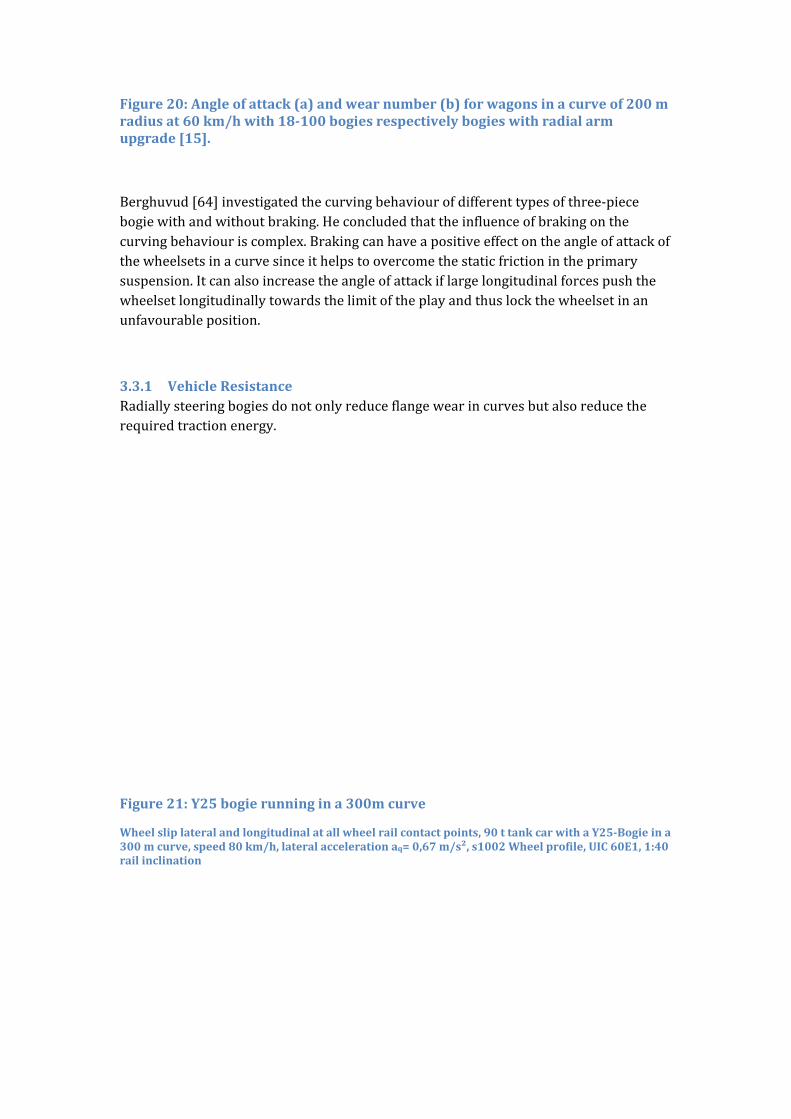
Figure20:Angleofattack(a)andwearnumber(b)forwagonsinacurveof200mradiusat60km/hwith18‐100bogiesrespectivelybogieswithradialarmupgrade[15].
Berghuvud[64]investigatedthecurvingbehaviourofdifferenttypesofthree‐piecebogiewithandwithoutbraking.Heconcludedthattheinfluenceofbrakingonthecurvingbehaviouriscomplex.Brakingcanhaveapositiveeffectontheangleofattackofthewheelsetsinacurvesinceithelpstoovercomethestaticfrictionintheprimarysuspension.Itcanalsoincreasetheangleofattackiflargelongitudinalforcespushthewheelsetlongitudinallytowardsthelimitoftheplayandthuslockthewheelsetinanunfavourableposition.
3.3.1 VehicleResistanceRadiallysteeringbogiesdonotonlyreduceflangewearincurvesbutalsoreducetherequiredtractionenergy.
Figure21:Y25bogierunningina300mcurve
Wheelsliplateralandlongitudinalatallwheelrailcontactpoints,90ttankcarwithaY25‐Bogieina300mcurve,speed80km/h,lateralaccelerationaq=0,67m/s²,s1002Wheelprofile,UIC60E1,1:40railinclination
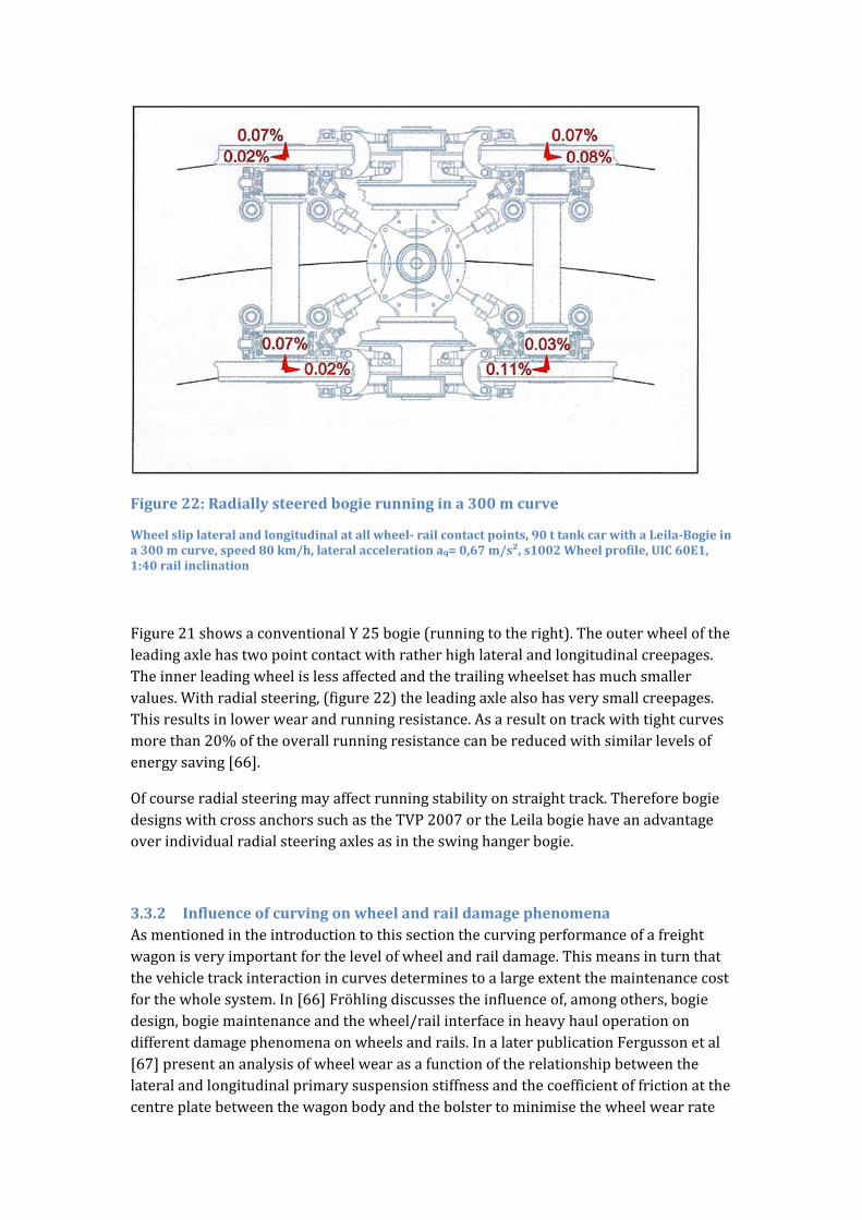
Figure22:Radiallysteeredbogierunningina300mcurve
Wheelsliplateralandlongitudinalatallwheel‐railcontactpoints,90ttankcarwithaLeila‐Bogieina300mcurve,speed80km/h,lateralaccelerationaq=0,67m/s²,s1002Wheelprofile,UIC60E1,1:40railinclination
Figure21showsaconventionalY25bogie(runningtotheright).Theouterwheeloftheleadingaxlehastwopointcontactwithratherhighlateralandlongitudinalcreepages.Theinnerleadingwheelislessaffectedandthetrailingwheelsethasmuchsmallervalues.Withradialsteering,(figure22)theleadingaxlealsohasverysmallcreepages.Thisresultsinlowerwearandrunningresistance.Asaresultontrackwithtightcurvesmorethan20%oftheoverallrunningresistancecanbereducedwithsimilarlevelsofenergysaving[66].
Ofcourseradialsteeringmayaffectrunningstabilityonstraighttrack.ThereforebogiedesignswithcrossanchorssuchastheTVP2007ortheLeilabogiehaveanadvantageoverindividualradialsteeringaxlesasintheswinghangerbogie.
3.3.2 InfluenceofcurvingonwheelandraildamagephenomenaAsmentionedintheintroductiontothissectionthecurvingperformanceofafreightwagonisveryimportantforthelevelofwheelandraildamage.Thismeansinturnthatthevehicletrackinteractionincurvesdeterminestoalargeextentthemaintenancecostforthewholesystem.In[66]Fröhlingdiscussestheinfluenceof,amongothers,bogiedesign,bogiemaintenanceandthewheel/railinterfaceinheavyhauloperationondifferentdamagephenomenaonwheelsandrails.InalaterpublicationFergussonetal[67]presentananalysisofwheelwearasafunctionoftherelationshipbetweenthelateralandlongitudinalprimarysuspensionstiffnessandthecoefficientoffrictionatthecentreplatebetweenthewagonbodyandthebolstertominimisethewheelwearrate
ofaself‐steeringthree‐piecebogiewithoutcompromisingvehiclestability.Simulationresultsindicatethatwheelwearistheoreticallythelowestforlowlateralandlongitudinalprimarysuspensionstiffnessandnofrictionatthecentreplate.Casanuevaetal[68]extendthewearpredictionmethodologyforfreightwagonstoalsoincludeswitchesandcrossings.Itisconcludedthatwearonsomepartsofthewheelprofilecanonlybeexplainedwithrunningthroughswitches.
TunnaandUrban[69]carriedoutaparametricstudytoquantifytheeffectsofvariousfreightvehicleparametersonthegenerationofRCF.Threedifferentfreightsuspensionswerconsidered:anenhancedthree‐piecebogie,arigid‐framebogiewithprimarysuspension,andatwo‐axlevehiclewithleafsprings.Simulationswereperformedfortrackcurvaturerangingfrom400to10000m.TojudgethegenerationofRCFtheTgammamodelfromBurstow[70]wasused.Itisstatedthatparametersthatclearlyneedtobeconsideredwhenevaluatingrailsurfacedamagearecurvedistribution,trackquality,conicity,vehicletypeandloadingstateofthewagon.Sinceseveralparametersarelinedependentitisconcludedthataroutebasedanalysisisnecessary.
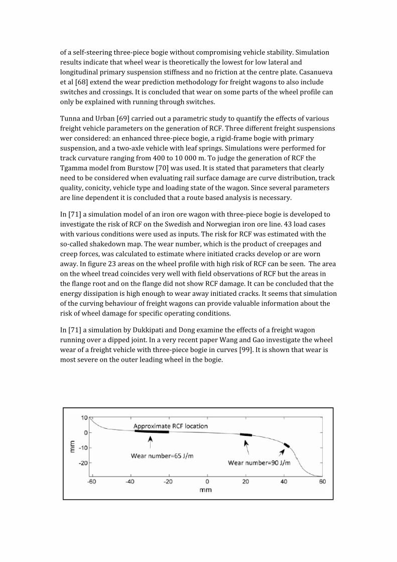
In[71]asimulationmodelofanironorewagonwiththree‐piecebogieisdevelopedtoinvestigatetheriskofRCFontheSwedishandNorwegianironoreline.43loadcaseswithvariousconditionswereusedasinputs.TheriskforRCFwasestimatedwiththeso‐calledshakedownmap.Thewearnumber,whichistheproductofcreepagesandcreepforces,wascalculatedtoestimatewhereinitiatedcracksdeveloporarewornaway.Infigure23areasonthewheelprofilewithhighriskofRCFcanbeseen.TheareaonthewheeltreadcoincidesverywellwithfieldobservationsofRCFbuttheareasintheflangerootandontheflangedidnotshowRCFdamage.Itcanbeconcludedthattheenergydissipationishighenoughtowearawayinitiatedcracks.Itseemsthatsimulationofthecurvingbehaviouroffreightwagonscanprovidevaluableinformationabouttheriskofwheeldamageforspecificoperatingconditions.
In[71]asimulationbyDukkipatiandDongexaminetheeffectsofafreightwagonrunningoveradippedjoint.InaveryrecentpaperWangandGaoinvestigatethewheelwearofafreightvehiclewiththree‐piecebogieincurves[99].Itisshownthatwearismostsevereontheouterleadingwheelinthebogie.
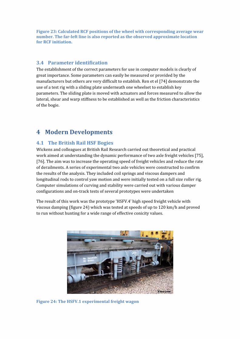
Figure23:CalculatedRCFpositionsofthewheelwithcorrespondingaveragewearnumber.Thefar‐leftlineisalsoreportedastheobservedapproximatelocationforRCFinitiation.
3.4 ParameteridentificationTheestablishmentofthecorrectparametersforuseincomputermodelsisclearlyofgreatimportance.Someparameterscaneasilybemeasuredorprovidedbythemanufacturersbutothersareverydifficulttoestablish.Renetel[74]demonstratetheuseofatestrigwithaslidingplateunderneathonewheelsettoestablishkeyparameters.Theslidingplateismovedwithactuatorsandforcesmeasuredtoallowthelateral,shearandwarpstiffnesstobeestablishedaswellasthefrictioncharacteristicsofthebogie.
4 ModernDevelopments
4.1 TheBritishRailHSFBogiesWickensandcolleaguesatBritishRailResearchcarriedouttheoreticalandpracticalworkaimedatunderstandingthedynamicperformanceoftwoaxlefreightvehicles[75],[76].Theaimwastoincreasetheoperatingspeedoffreightvehiclesandreducetherateofderailments.Aseriesofexperimentaltwoaxlevehicleswereconstructedtoconfirmtheresultsoftheanalysis.Theyincludedcoilspringsandviscousdampersandlongitudinalrodstocontrolyawmotionandwereinitiallytestedonafullsizerollerrig.Computersimulationsofcurvingandstabilitywerecarriedoutwithvariousdamperconfigurationsandon‐tracktestsofseveralprototypeswereundertaken
Theresultofthisworkwastheprototype‘HSFV.4’highspeedfreightvehiclewithviscousdamping(figure24)whichwastestedatspeedsofupto120km/handprovedtorunwithouthuntingforawiderangeofeffectiveconicityvalues.
Figure24:TheHSFV.1experimentalfreightwagon

4.2 TheUnitruckrunninggearTheUnitrucksingle‐axlerunninggearwithlateral“swinghangers”wasfirstdevelopedfortheAmericanmarketandinthe1990’sadjustedtosuitEuropeanconditions.VehicleswithUnitruckrunninggear[76]aretodayusedbothinNorthAmericaandEurope.Theyhaveonlyonestagesuspension,whichalsoincludesfrictiondamping.AsintheY25bogie,theverticalforceintheprimarysuspensionisusedtopreloadthedifferentfrictioncomponentsviaaninclinedsurface.Figure25leftshowsthewedgeelement,whichisinserieswithoneofthecoilspringsandincontactwiththecarbodyviaaninclinedfrictionsurface;theverticalsurfaceincontactwiththesaddleisalsoafrictionsurface.Newerdesignshavesubstitutedtheinclinedfrictionsurfacebyaroller(figure25left)[77],thusenablingthedisplacementinthelongitudinaldirection,butreducinglongitudinaldamping.Also,addingacouplingplateinthecentreofthecoilspringsincreaseslongitudinalstiffness(Figure25right),whichimprovescriticalspeedcomparedtotherunninggearwithrollersandclassiccoilsprings.
Figure25:Unitruckrunninggear(left)andmodificationsforimprovingcurvingbehaviour(right).
4.3 The‘SwingMotion’Bogie
Figure26:The‘Swingmotion’bogie
The‘SwingMotion’bogie(figure26)isavariantofthethree‐piecefreightbogieandwasoriginallydevelopedforheavyhauloperationsinNorthAmerica.IntheSwingMotiondesignanadditionalcrossmemberortransomisincludedwhichconnectsthetwosideframestogetherviapivotsatthebaseofthesecondaryspringpack.Thebolsterstillsitsonthetopofthespringpacksandisdampedthroughfrictionwedges.Apivotbetweentheaxleboxesandthesideframesisalsoincludedsothatthesideframescanpivotorswingtoaccommodatelateralmotionofthebolster.Theswingmotiongivesincreasedlateralstabilityatspeedsupto176km/handisclaimedtoreducewheelandrailwear,reducerollingresistanceandforcesontrackandvehiclebodycomparedwithstandardthree‐piecebogies.
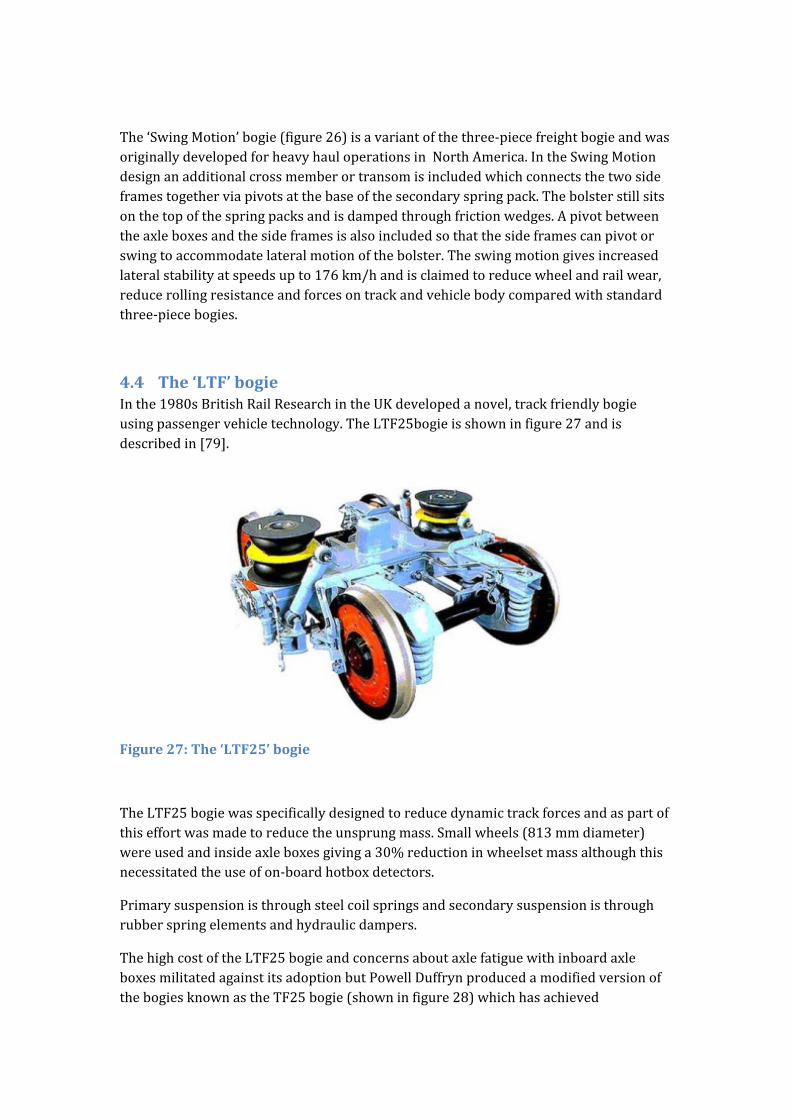
4.4 The‘LTF’bogieInthe1980sBritishRailResearchintheUKdevelopedanovel,trackfriendlybogieusingpassengervehicletechnology.TheLTF25bogieisshowninfigure27andisdescribedin[79].
Figure27:The‘LTF25’bogie
TheLTF25bogiewasspecificallydesignedtoreducedynamictrackforcesandaspartofthiseffortwasmadetoreducetheunsprungmass.Smallwheels(813mmdiameter)wereusedandinsideaxleboxesgivinga30%reductioninwheelsetmassalthoughthisnecessitatedtheuseofon‐boardhotboxdetectors.
Primarysuspensionisthroughsteelcoilspringsandsecondarysuspensionisthroughrubberspringelementsandhydraulicdampers.
ThehighcostoftheLTF25bogieandconcernsaboutaxlefatiguewithinboardaxleboxesmilitatedagainstitsadoptionbutPowellDuffrynproducedamodifiedversionofthebogiesknownastheTF25bogie(showninfigure28)whichhasachieved
considerableproductionsuccess.
Figure28:TheTF25bogie
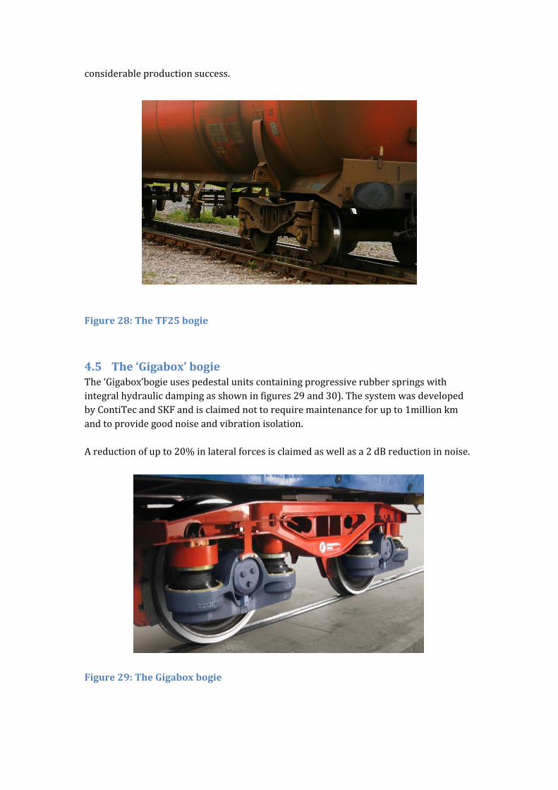
4.5 The‘Gigabox’bogieThe‘Gigabox’bogieusespedestalunitscontainingprogressiverubberspringswithintegralhydraulicdampingasshowninfigures29and30).ThesystemwasdevelopedbyContiTecandSKFandisclaimednottorequiremaintenanceforupto1millionkmandtoprovidegoodnoiseandvibrationisolation.Areductionofupto20%inlateralforcesisclaimedaswellasa2dBreductioninnoise.
Figure29:TheGigaboxbogie
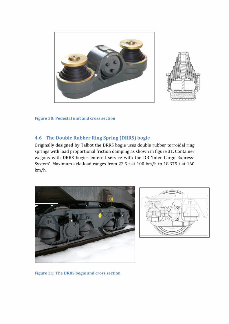
Figure30:Pedestalunitandcrosssection
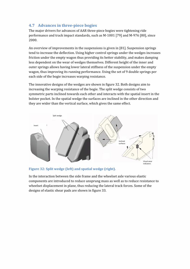
4.6 TheDoubleRubberRingSpring(DRRS)bogieOriginallydesignedbyTalbottheDRRSbogieusesdoublerubbertorroidalringspringswithloadproportionalfrictiondampingasshowninfigure31.Containerwagons with DRRS bogies entered service with the DB ‘Inter Cargo Express‐System’.Maximumaxle‐loadrangesfrom22.5tat100km/hto18.375tat160km/h.
Figure31:TheDRRSbogieandcrosssection
4.7 Advancesinthree‐piecebogiesThemajordriversforadvancesofAARthree‐piecebogiesweretighteningrideperformanceandtrackimpactstandards,suchasM‐1001[79]andM‐976[80],since2000.
Anoverviewofimprovementsinthesuspensionsisgivenin[81].Suspensionspringstendtoincreasethedeflection.Usinghighercontrolspringsunderthewedgesincreasesfrictionundertheemptywagonthusprovidingitsbetterstability,andmakesdampinglessdependentonthewearofwedgesthemselves.Differentheightoftheinnerandouterspringsallowshavinglowerlateralstiffnessofthesuspensionundertheemptywagon,thusimprovingitsrunningperformance.Usingthesetof9doublespringspereachsideofthebogieincreaseswarpingresistance.
Theinnovativedesignsofthewedgesareshowninfigure32.Bothdesignsaimtoincreasingthewarpingresistanceofthebogie.Thesplitwedgeconsistsoftwosymmetricpartsinclinedtowardseachotherandinteractswiththespatialinsertinthebolsterpocket.Inthespatialwedgethesurfacesareinclinedintheotherdirectionandtheyarewiderthantheverticalsurface,whichgivesthesameeffect.
Figure32:Splitwedge(left)andspatialwedge(right).
Intheinteractionbetweenthesideframeandthewheelsetaxlevariouselasticcomponentsareintroducedtoreduceunsprungmassaswellastoreduceresistancetowheelsetdisplacementinplane,thusreducingthelateraltrackforces.Someofthedesignsofelasticshearpadsareshowninfigure33.
Split wedge
Insert
Inclined surfaces
Visual wear indicators
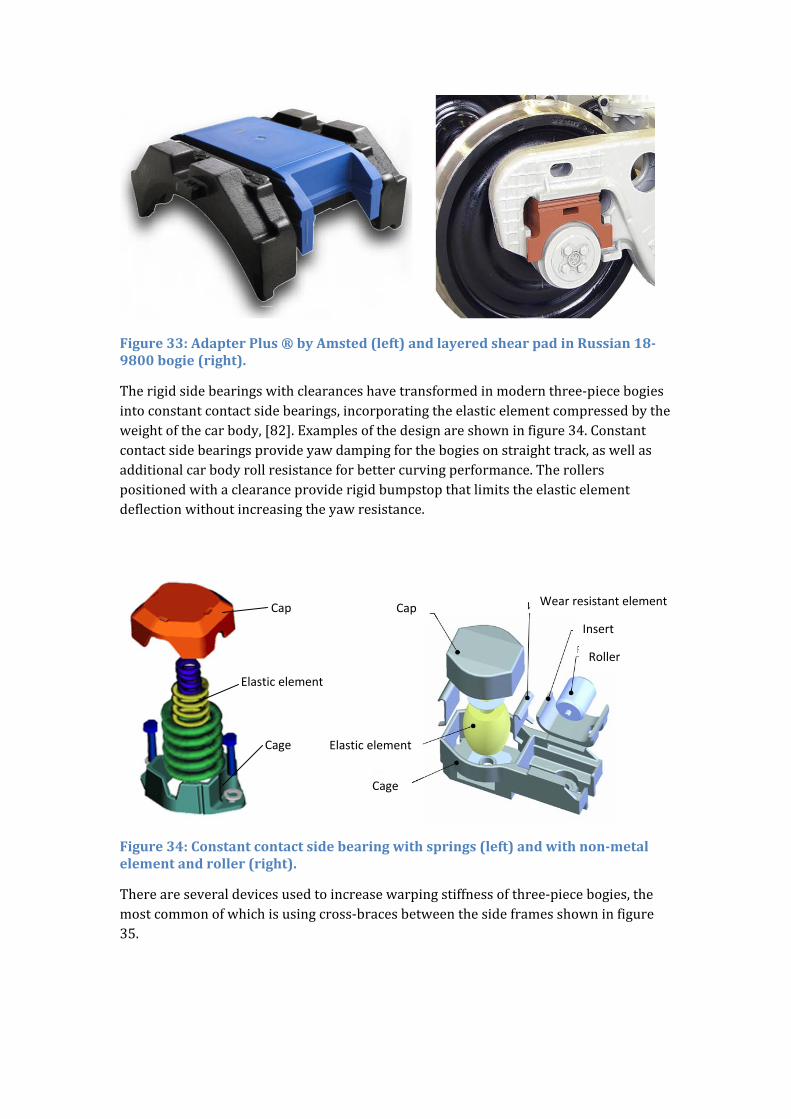
Figure33:AdapterPlus®byAmsted(left)andlayeredshearpadinRussian18‐9800bogie(right).
Therigidsidebearingswithclearanceshavetransformedinmodernthree‐piecebogiesintoconstantcontactsidebearings,incorporatingtheelasticelementcompressedbytheweightofthecarbody,[82].Examplesofthedesignareshowninfigure34.Constantcontactsidebearingsprovideyawdampingforthebogiesonstraighttrack,aswellasadditionalcarbodyrollresistanceforbettercurvingperformance.Therollerspositionedwithaclearanceproviderigidbumpstopthatlimitstheelasticelementdeflectionwithoutincreasingtheyawresistance.
Figure34:Constantcontactsidebearingwithsprings(left)andwithnon‐metalelementandroller(right).
Thereareseveraldevicesusedtoincreasewarpingstiffnessofthree‐piecebogies,themostcommonofwhichisusingcross‐bracesbetweenthesideframesshowninfigure35.
Cap
Elastic element
Cage
Wear resistant element
Insert
Roller
Cap
Elastic element
Cage
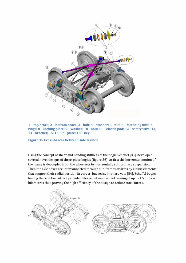
1–topbrace;2–bottombrace;3‐bolt;4–washer;5‐nut;6–fasteningunit;7–rings;8–lockingplate;9–washer;10‐bolt;11–elasticpad;12–safetywire;13,14‐bracket;15,16,17‐plate;18–key
Figure35Cross‐bracesbetweensideframes.
UsingtheconceptofshearandbendingstiffnessofthebogieScheffel[83],developedseveralnoveldesignsofthree‐piecebogies(figure36).Atfirstthehorizontalmotionoftheframeisdecoupledfromthewheelsetsbyhorizontallysoftprimarysuspension.Thentheaxleboxesareinterconnectedthroughsub‐framesorarmsbyelasticelementsthatsupporttheirradialpositionincurves,butresistin‐phaseyaw[84].Scheffelbogieshavingtheaxleloadof32tprovidemileagebetweenwheelturningofupto1.5millionkilometresthusprovingthehighefficiencyofthedesigntoreducetrackforces.
1‐sideframe;2‐bolster;3‐wheelset;4–primarysuspension;5–elasticconnectionbetweensub‐frames
Figure36:ScheffelHSbogie(left)andbogieretrofittedwithRadialArmdesign(right).
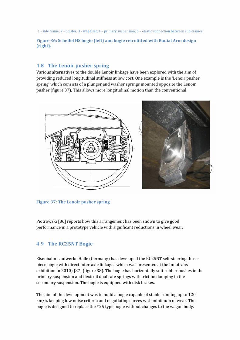
4.8 TheLenoirpusherspringVariousalternativestothedoubleLenoirlinkagehavebeenexploredwiththeaimofprovidingreducedlongitudinalstiffnessatlowcost.Oneexampleisthe‘Lenoirpusherspring’whichconsistsofaplungerandwasherspringsmountedoppositetheLenoirpusher(figure37).Thisallowsmorelongitudinalmotionthantheconventional
Figure37:TheLenoirpusherspring
Piotrowski[86]reportshowthisarrangementhasbeenshowntogivegoodperformanceinaprototypevehiclewithsignificantreductionsinwheelwear.
4.9 TheRC25NTBogie
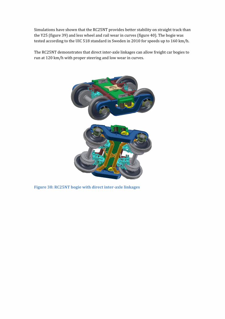
EisenbahnLaufwerkeHalle(Germany)hasdevelopedtheRC25NTself‐steeringthree‐piecebogiewithdirectinter‐axlelinkageswhichwaspresentedattheInnotransexhibitionin2010)[87](figure38).Thebogiehashorizontallysoftrubberbushesintheprimarysuspensionandflexicoildualratespringswithfrictiondampinginthesecondarysuspension.Thebogieisequippedwithdiskbrakes.Theaimofthedevelopmentwastobuildabogiecapableofstablerunningupto120km/h,keepinglownoisecriteriaandnegotiatingcurveswithminimumofwear.ThebogieisdesignedtoreplacetheY25typebogiewithoutchangestothewagonbody.
SimulationshaveshownthattheRC25NTprovidesbetterstabilityonstraighttrackthantheY25(figure39)andlesswheelandrailwearincurves(figure40).ThebogiewastestedaccordingtotheUIC518standardinSwedenin2010forspeedsupto160km/h.TheRC25NTdemonstratesthatdirectinter‐axlelinkagescanallowfreightcarbogiestorunat120km/hwithpropersteeringandlowwearincurves.
Figure38:RC25NTbogiewithdirectinter‐axlelinkages
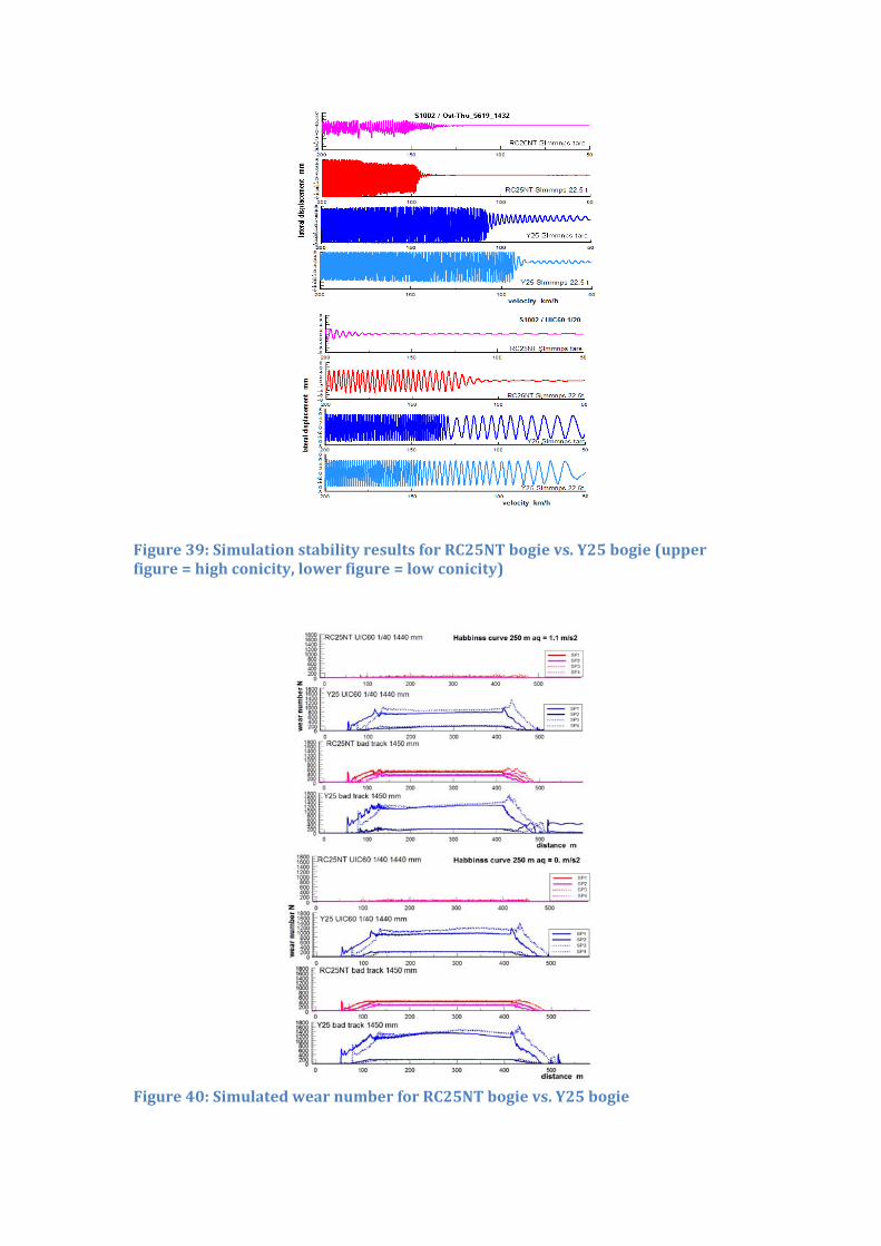
Figure39:SimulationstabilityresultsforRC25NTbogievs.Y25bogie(upperfigure=highconicity,lowerfigure=lowconicity)
Figure40:SimulatedwearnumberforRC25NTbogievs.Y25bogie

4.10 The‘LEILA’BogieTheLEILAbogie(‘LEIchtesundLärmArmesGüterwagenDrehGestell’withthemeaningoflightandlownoisefreightbogie)isapassiveradialsteeringbogiewithamaximumaxleloadof22.5tandwasdevelopedbetween2000and2005duringaGermanandSwissresearchproject[88].TheInstituteofRailVehiclesoftheTechnischeUniversitätBerlinwasoneoftheinvolvedpartner.Theaimtodevelopthisbogiewas:
toreducethenoiseemissionsoffreightwagons; toreducethemassofabogietobeunder4tand toreducesignificantlywearandrunningresistance.
Inaddition:
thereliabilityandavailabilityoffreightwagons; transparencyinthetransportchain; theactiveandpassivesafetyofthefreighttrafficand; thetransportvelocityshouldbesimilarlyincreased[89].
Figure41and42showthemaincomponentsofthisbogie.ComparedtothestandardbogiessuchasY25,theLEILAbogiehasinnerbearings.Theresultingbetterforceflowleadtoaweightreductionofthebogieframeandwheelsetresultinginanoverallweightreductionof750kgperbogiecomparedtoY25bogie.Atthewebofthewheels(diameter:920mm),discbrakesaremounted.Theprimarylayerconsistsofrubberspringsandtheloaddependentstiffnesscharacteristicsareseparatedinverticalandhorizontalworkingcomponents.Thebogiehaspassiveradialsteeringtechnologyofthewheelsets.Wheelsetsareabletorotateabouttheverticalaxiswithoutanyexternalenergybutonlybytherollradiusdifferencebetweentheinnerandouterwheel.Bothwheelsetsareconnectedwithcrossanchors;mountedonoppositeaxleboxes.ThesecondarylayerisdefinedUICcentreofpivotandsidebearer(latterguaranteestheexchangeabilitytoY25bogies).Inaddition,thecentreofpivothasanelasticallybearingusingasecondaryrubberspring.TheLEILAbogieprototypewasexaminedduringvariousfieldtestswhereitdemonstrateditsadvantagescomparedtoaY25bogie.Thenoiseemissionswerereducedupto18dB(A)comparedtoaY25bogiewithcastironbrakeblocksandupto8dB(A)comparedtoaY25bogiewithcompositeblocks(k‐blocks).Butthebogiefailedatthattimetoenterthemarket.Duringtheverygoodongoinghomologationprocesstheproducerofthebogiedecidedtostoptheproductionofnewfreightwagonsandbogies.Thereforethehomologationwasstoppedandnotfinishedjustforcommercialreasons.RightnowasmoreandmoreEMUsareproducedwithinnerbearingsitisexpectedthattheacceptabilityofinnerbearingbogieswiththeadvantageslessweightandlowerforcesattheaxlesincurveswillbemoreacceptable.
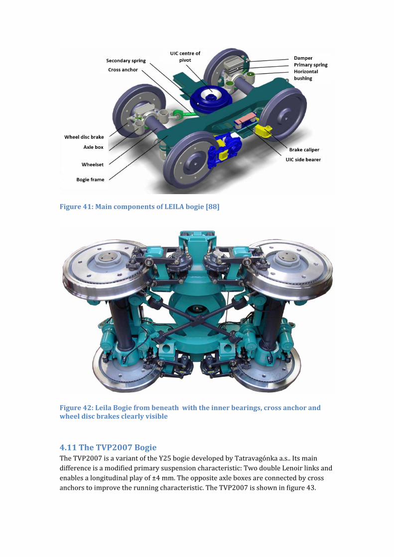
Figure41:MaincomponentsofLEILAbogie[88]
Figure42:LeilaBogiefrombeneathwiththeinnerbearings,crossanchorandwheeldiscbrakesclearlyvisible
4.11 TheTVP2007BogieTheTVP2007isavariantoftheY25bogiedevelopedbyTatravagónkaa.s..Itsmaindifferenceisamodifiedprimarysuspensioncharacteristic:TwodoubleLenoirlinksandenablesalongitudinalplayof±4mm.Theoppositeaxleboxesareconnectedbycrossanchorstoimprovetherunningcharacteristic.TheTVP2007isshowninfigure43.
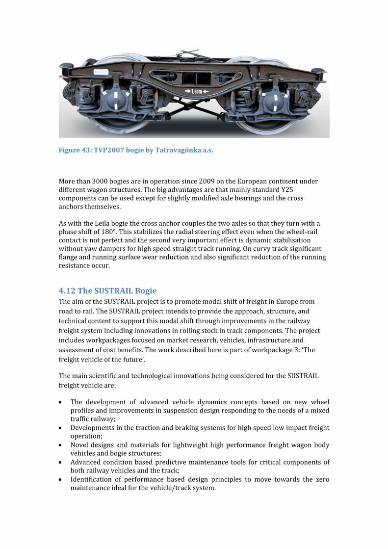
Figure43:TVP2007bogiebyTatravagónkaa.s.
Morethan3000bogiesareinoperationsince2009ontheEuropeancontinentunderdifferentwagonstructures.ThebigadvantagesarethatmainlystandardY25componentscanbeusedexceptforslightlymodifiedaxlebearingsandthecrossanchorsthemselves.AswiththeLeilabogiethecrossanchorcouplesthetwoaxlessothattheyturnwithaphaseshiftof180°.Thisstabilizestheradialsteeringeffectevenwhenthewheel‐railcontactisnotperfectandthesecondveryimportanteffectisdynamicstabilisationwithoutyawdampersforhighspeedstraighttrackrunning.Oncurvytracksignificantflangeandrunningsurfacewearreductionandalsosignificantreductionoftherunningresistanceoccur.
4.12 TheSUSTRAILBogieTheaimoftheSUSTRAILprojectistopromotemodalshiftoffreightinEuropefromroadtorail.TheSUSTRAILprojectintendstoprovidetheapproach,structure,andtechnicalcontenttosupportthismodalshiftthroughimprovementsintherailwayfreightsystemincludinginnovationsinrollingstockintrackcomponents.Theprojectincludesworkpackagesfocusedonmarketresearch,vehicles,infrastructureandassessmentofcostbenefits.Theworkdescribedhereispartofworkpackage3:‘Thefreightvehicleofthefuture’.
ThemainscientificandtechnologicalinnovationsbeingconsideredfortheSUSTRAILfreightvehicleare:
The development of advanced vehicle dynamics concepts based on new wheelprofilesandimprovementsinsuspensiondesignrespondingtotheneedsofamixedtrafficrailway;
Developmentsinthetractionandbrakingsystemsforhighspeedlowimpactfreightoperation;
Noveldesignsandmaterials for lightweighthighperformance freightwagonbodyvehiclesandbogiestructures;
Advancedconditionbasedpredictivemaintenance tools for critical componentsofbothrailwayvehiclesandthetrack;
Identification of performance based design principles to move towards the zeromaintenanceidealforthevehicle/tracksystem.
Partnersintheprojecthavecarriedoutatechnologyreviewtoidentifythepotentialinnovativetechnologiestomeettheaboverequirementsandtheresultshavebeenrankedandtwoconceptvehiclesarebeingdesigned.The‘Conventional’vehiclewilluseoptimisedexistingtechnologyandademonstratorforthisisbeingbuiltaspartoftheproject.The‘Futuristic’vehiclewillutilisetechnologywhichhasnotyetbeenprovenintherailwayfieldbuthaspotentialtomakegreaterimprovements.
Simulationshavebeencarriedoutofthedynamicbehaviouroftheconceptdesignvehiclesrunningontypicaltrackintare,partladenandfullyladencases.Inlinewiththetargetofa50%reductioninlateralforcesonthetrackandstablerunningat140km/hasuspensionusingdoubleLenoirlinkages,longitudinallinkagesbetweenaxleboxesandcentrepivotsuspensionhasbeenselected.Computersimulationhasbeenusedtooptimisethesuspensionandtoselectsuitableparametersforthevariouscomponents.Assessmentoftheresultsisbasedon:
Stability:stablerunningontypicalEuropeantrackatthedesignspeedof140km/hmust be ensured and ride quality (vertical lateral and longitudinal accelerationsexperiencedbythegoodstransported)willbeassessed.
Reduced track forces: track geometrical deterioration (ballast settlement andhorizontallevel,alignmentandbuckling),railsurfacedamage(wear,rollingcontactfatigue – RCF) and track components damage (sleeper cracking, rail paddeterioration,railfatigue,fasteningdeterioration)willallbeassessed.
AbenchmarkvehiclehasbeenselectedbasedonaY25bogieandflatbedwagonandhasbeenusedtoallowquantificationofthebenefitsofthenewdesign.
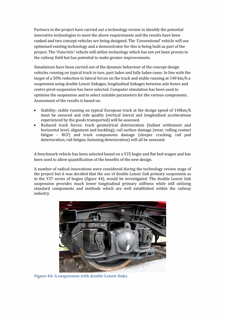
AnumberofradicalinnovationswereconsideredduringthetechnologyreviewstageoftheprojectbutitwasdecidedthattheuseofdoubleLenoirlinkprimarysuspensionasin theY37 series of bogies (figure44),would be investigated.ThedoubleLenoir linksuspension provides much lower longitudinal primary stiffness while still utilisingstandard components and methods which are well established within the railwayindustry.
Figure44:AsuspensionwithdoubleLenoirlinks
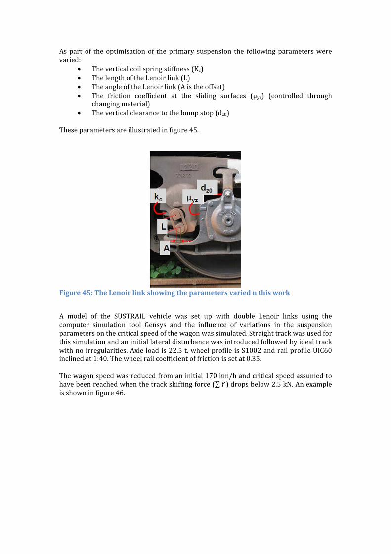
Aspart of the optimisation of theprimary suspension the followingparameterswerevaried:
Theverticalcoilspringstiffness(Kc) ThelengthoftheLenoirlink(L) TheangleoftheLenoirlink(Aistheoffset) The friction coefficient at the sliding surfaces (μyz) (controlled through
changingmaterial) Theverticalclearancetothebumpstop(dz0)
Theseparametersareillustratedinfigure45.
Figure45:TheLenoirlinkshowingtheparametersvariednthiswork
A model of the SUSTRAIL vehicle was set up with double Lenoir links using thecomputer simulation tool Gensys and the influence of variations in the suspensionparametersonthecriticalspeedofthewagonwassimulated.Straighttrackwasusedforthissimulationandaninitiallateraldisturbancewasintroducedfollowedbyidealtrackwithnoirregularities.Axle loadis22.5t,wheelprofile isS1002andrailprofileUIC60inclinedat1:40.Thewheelrailcoefficientoffrictionissetat0.35.Thewagonspeedwasreducedfromaninitial170km/handcriticalspeedassumedtohavebeenreachedwhenthetrackshiftingforce(∑ )dropsbelow2.5kN.Anexampleisshowninfigure46.
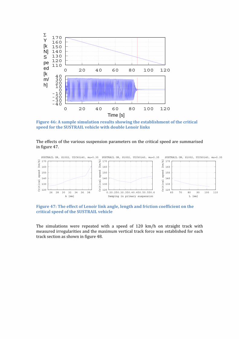
Figure46:AsamplesimulationresultsshowingtheestablishmentofthecriticalspeedfortheSUSTRAILvehiclewithdoubleLenoirlinks
Theeffectsofthevarioussuspensionparametersonthecriticalspeedaresummarisedinfigure47.
Figure47:TheeffectofLenoirlinkangle,lengthandfrictioncoefficientonthecriticalspeedoftheSUSTRAILvehicle
The simulations were repeated with a speed of 120 km/h on straight track withmeasuredirregularitiesandthemaximumverticaltrackforcewasestablishedforeachtracksectionasshowninfigure48.
120
130
140
150
160
170
26 28 30 32 34 36 38
Critical speed [km/h]
A [mm]
SUSTRAIL OR, S1002, UIC60i40, mu=0.35
120
130
140
150
160
170
0.20.250.30.350.40.450.50.550.6
Critical speed [km/h]
Damping in primary suspension
SUSTRAIL OR, S1002, UIC60i40, mu=0.35
120
130
140
150
160
170
60 70 80 90 100 110
Critical speed [km/h]
L [mm]
SUSTRAIL OR, S1002, UIC60i40, mu=0.35
110120130140150160170
0 20 40 60 80 100 120
-40-30-20-10
010203040
0 20 40 60 80 100 120
Time [s]
Y [kN] Speed [km/h]
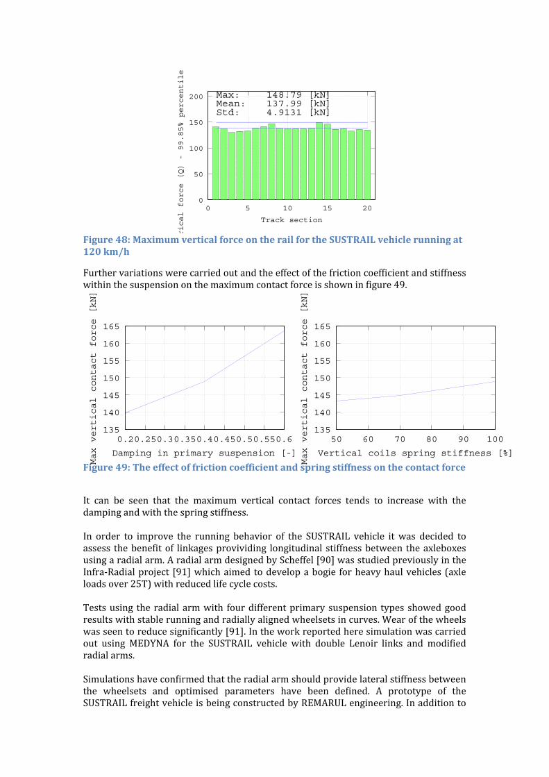
Figure48:MaximumverticalforceontherailfortheSUSTRAILvehiclerunningat120km/h
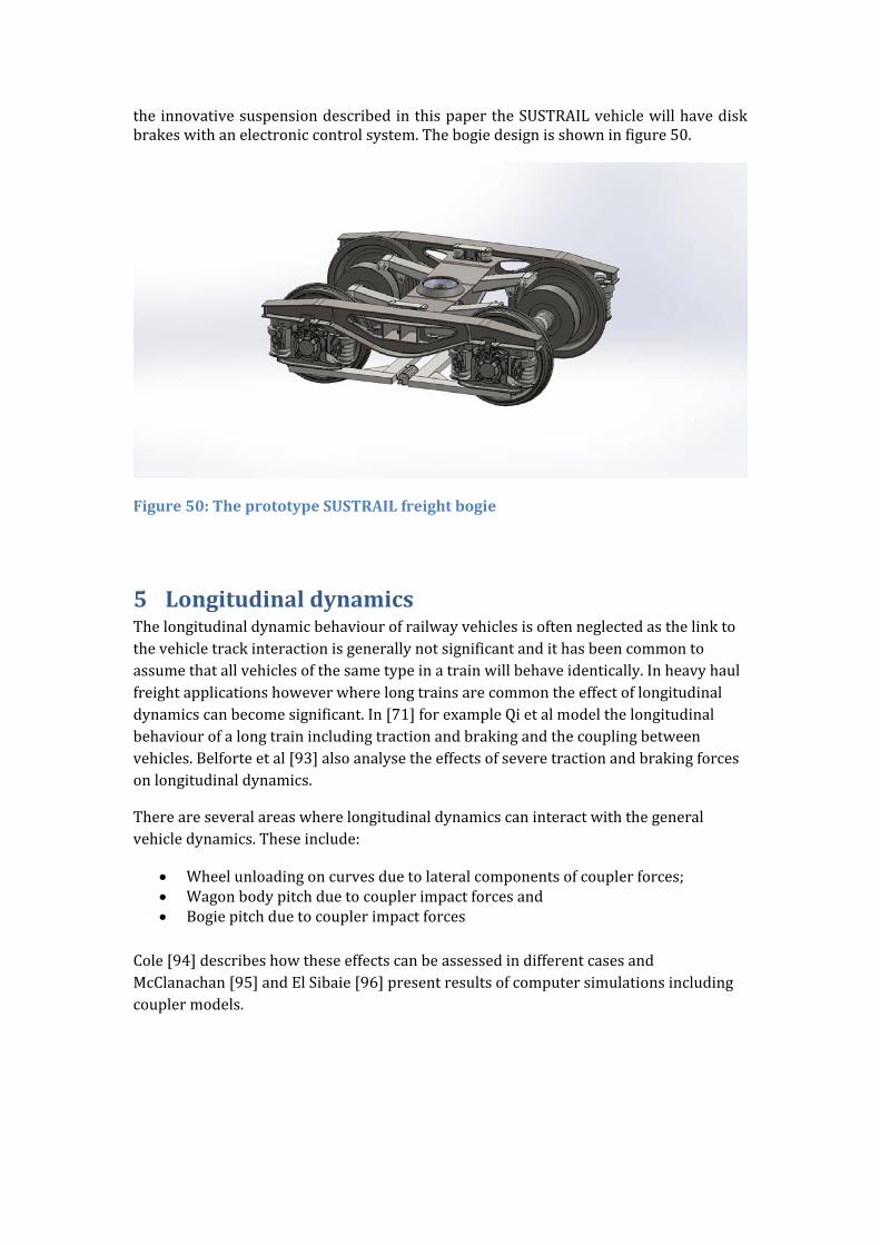
Furthervariationswerecarriedoutandtheeffectofthefrictioncoefficientandstiffnesswithinthesuspensiononthemaximumcontactforceisshowninfigure49.
Figure49:Theeffectoffrictioncoefficientandspringstiffnessonthecontactforce
It can be seen that the maximum vertical contact forces tends to increase with thedampingandwiththespringstiffness.In order to improve the running behavior of the SUSTRAIL vehicle it was decided toassess thebenefitof linkagesprovividing longitudinal stiffnessbetween theaxleboxesusingaradialarm.AradialarmdesignedbyScheffel[90]wasstudiedpreviouslyintheInfra‐Radialproject [91]whichaimedtodevelopabogie forheavyhaulvehicles(axleloadsover25T)withreducedlifecyclecosts.Testsusing theradialarmwith fourdifferentprimarysuspension types showedgoodresultswithstablerunningandradiallyalignedwheelsetsincurves.Wearofthewheelswasseentoreducesignificantly[91].Intheworkreportedheresimulationwascarriedout using MEDYNA for the SUSTRAIL vehicle with double Lenoir links and modifiedradialarms.Simulationshaveconfirmedthattheradialarmshouldprovidelateralstiffnessbetweenthe wheelsets and optimised parameters have been defined. A prototype of theSUSTRAILfreightvehicleisbeingconstructedbyREMARULengineering.Inadditionto
0
50
100
150
200
0 5 10 15 20
rical force (Q) - 99.85% percentile
Track section
Max:Mean:Std:
148.79 [kN]137.99 [kN]4.9131 [kN]
135
140
145
150
155
160
165
0.20.250.30.350.40.450.50.550.6
Max vertical contact force [kN]
Damping in primary suspension [-]
135
140
145
150
155
160
165
50 60 70 80 90 100
Max vertical contact force [kN]
Vertical coils spring stiffness [%]
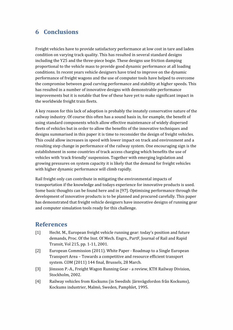
theinnovativesuspensiondescribedinthispapertheSUSTRAILvehiclewillhavediskbrakeswithanelectroniccontrolsystem.Thebogiedesignisshowninfigure50.
Figure50:TheprototypeSUSTRAILfreightbogie
5 LongitudinaldynamicsThelongitudinaldynamicbehaviourofrailwayvehiclesisoftenneglectedasthelinktothevehicletrackinteractionisgenerallynotsignificantandithasbeencommontoassumethatallvehiclesofthesametypeinatrainwillbehaveidentically.Inheavyhaulfreightapplicationshoweverwherelongtrainsarecommontheeffectoflongitudinaldynamicscanbecomesignificant.In[71]forexampleQietalmodelthelongitudinalbehaviourofalongtrainincludingtractionandbrakingandthecouplingbetweenvehicles.Belforteetal[93]alsoanalysetheeffectsofseveretractionandbrakingforcesonlongitudinaldynamics.
Thereareseveralareaswherelongitudinaldynamicscaninteractwiththegeneralvehicledynamics.Theseinclude:
Wheelunloadingoncurvesduetolateralcomponentsofcouplerforces; Wagonbodypitchduetocouplerimpactforcesand Bogiepitchduetocouplerimpactforces
Cole[94]describeshowtheseeffectscanbeassessedindifferentcasesandMcClanachan[95]andElSibaie[96]presentresultsofcomputersimulationsincludingcouplermodels.
6 Conclusions
Freightvehicleshavetoprovidesatisfactoryperformanceatlowcostintareandladenconditiononvaryingtrackquality.ThishasresultedinseveralstandarddesignsincludingtheY25andthethree‐piecebogie.Thesedesignsusefrictiondampingproportionaltothevehiclemasstoprovidegooddynamicperformanceatallloadingconditions.Inrecentyearsvehicledesignershavetriedtoimproveonthedynamicperformanceoffreightwagonsandtheuseofcomputertoolshavehelpedtoovercomethecompromisebetweengoodcurvingperformanceandstabilityathigherspeeds.Thishasresultedinanumberofinnovativedesignswithdemonstrableperformanceimprovementsbutitisnotablethatfewofthesehaveyettomakesignificantimpactintheworldwidefreighttrainfleets.
Akeyreasonforthislackofadoptionisprobablytheinnatelyconservativenatureoftherailwayindustry.Ofcoursethisoftenhasasoundbasisin,forexample,thebenefitofusingstandardcomponentswhichalloweffectivemaintenanceofwidelydispersedfleetsofvehiclesbutinordertoallowthebenefitsoftheinnovativetechniquesanddesignssummarisedinthispaperitistimetoreconsiderthedesignoffreightvehicles.Thiscouldallowincreasesinspeedwithlowerimpactontrackandenvironmentandaresultingstepchangeinperformanceoftherailwaysystem.Oneencouragingsignistheestablishmentinsomecountriesoftrackaccesschargingwhichbenefitstheuseofvehicleswith‘trackfriendly’suspension.Togetherwithemerginglegislationandgrowingpressuresonsystemcapacityitislikelythatthedemandforfreightvehicleswithhigherdynamicperformancewillclimbrapidly.
Railfreightonlycancontributeinmitigatingtheenvironmentalimpactsoftransportationiftheknowledgeandtodaysexperienceforinnovativeproductsisused.Somebasicthoughtscanbefoundhereandin[97].Optimisingperformancethroughthedevelopmentofinnovativeproductsistobeplannedandprocuredcarefully.Thispaperhasdemonstratedthatfreightvehicledesignershaveinnovativedesignsofrunninggearandcomputersimulationtoolsreadyforthischallenge.
References[1] Hecht.M.,Europeanfreightvehiclerunninggear:today’spositionandfuture
demands,Proc.OftheInst.OfMech.Engrs.,PartF,JournalofRailandRapidTransit,Vol215,pp.1‐11,2001.
[2] EuropeanCommission(2011).WhitePaper‐RoadmaptoaSingleEuropeanTransportArea–Towardsacompetitiveandresourceefficienttransportsystem.COM(2011)144final,Brussels,28March.
[3] JönssonP.‐A.,FreightWagonRunningGear‐areview,KTHRailwayDivision,Stockholm,2002.
[4] RailwayvehiclesfromKockums(inSwedish:JärnvägsfordonfrånKockums),Kockumsindustrier,Malmö,Sweden,Pamphlet,1995.
[5] UICCode517.Wagons–Suspensiongear(Standardisation),6thedition1‐7‐79,Reprint1‐1‐89,incorporating8amendments.
[6] MadeyskiT.LaufwerkskonstruktionundErhöhungderRadsatzlastenimGüterverkehr.ZEV‐GlasersAnnalen107,pp.139‐147,1983.
[7] MüllerL.andNiedermeyerW.,WeiterentwickelteGüterwagendrehgestellederDeutschenBundesbahnfür22.5tRadsatzlast–wiedernachdemLenkachsenprinzip.ZEV‐GlasersAnnalen111,pp.188‐196,1987.
[8] LangeH.,“DynamicanalysisofafreightcarwithstandardUICsingle‐axlerunninggear,”KTHRailwayTechnology,Stockholm,TRITA‐FKTReport1996:34,1996.
[9] StichelS..Runningbehaviorofrailwayfreightwagonwithsingleaxlerunninggear,TRITA‐FKTReport1998:40,DivisionofRailwayTechnology,KTH,1998.
[10] StichelS.HowtoimprovetherunningbehavioroffreightwagonswithUIC‐linksuspension.VehicleSystemDynamicsSupplement33,pp.394‐405,1999.
[11] Stichel,S.Runningbehavioroffreightwagonswithlinkbogies.TRITA‐FKTReport1999:12,DivisionofRailwayTechnology,KTH,1999.
[12] SpechtW.NeueErkenntnisseüberdasVerschleissverhaltenvonGüterwagendrehgestellen,ZEVGlasersAnnalen111,pp.271‐280,1987.
[13] AssociationofAmericanRailroads.Manualofstandardsandrecommendedpractices.SectionD.Trucksandtruckdetails,2010,130p.
[14] GOST9246‐2013Bogiestwo‐axlethree‐pieceforfreightwagonsof1520mmgaugerailways.Generaltechnicalspecifications.38p.
[15] OrlovaA.,andRomenYu.,Refiningthewedgefrictiondamperofthree‐piecefreightbogies.VehicleSystemDynamics,Vol.46,Issue1&2,2008,pp445‐455
[16] BoronenkoY.,OrlovaA.,RudakovaE..Influenceofconstructionschemesandparametersofthree‐piecefreightbogiesonwagonstability,rideandcurvingqualities.VehicleSystemDynamics,Vol.44,Supplement,2006,402–414.
[17] OrlovaA.Identificationofparametersforspatialwedgesystemimplementedinfreightbogiedesign.Proceedingsofthe10thmini‐conferenceonVehicleSystemDynamics,IdentificationandAnomalies.Ed.I.Zobory.ISBN9789634209683.‐Budapest:KomaromiNyomdaesKiadoKft.,2008,pp245‐252
[18] EickhoffB.M.,EvansJ.R.andMinnisA.J.,Areviewofmodelingmethodsforrailwayvehiclesuspensioncomponents.VehicleSystemDynamics:InternationalJournalofVehicleMechanicsandMobility,24:6‐7,469‐496,1995
[19] Brunis.,VinolasJ.,BergM.,PolachO.,andStichelS.,“Modellingofsuspensioncomponentsinarailvehicledynamicscontext,”VehicleSystemDynamics,vol.49,no.7,pp.1021–1072,2011.
[20] StichelS.,JönssonP‐A.,CasanuevaC.andHosseinNiaS.,ModelingandSimulationofFreightWagonwithSpecialattentiontothePredictionofTrackDamage.InternationalJournalofRailwayTechnologyVol.3,2014.
[21] KlauserP.E.,Modellingfrictionwedges,PartI:Thestate‐of‐the‐art.ProceedingsofIMECE042004ASMEInternationalMechanicalEngineeringCongress&Exposition,November13‐20,Anaheim(CA):AmericanSocietyofMechanicalEngineering,2004.

[22] WuQ.,ColeC.,SpiryaginMandSunQ.,Areviewofdynamicsmodellingoffrictionwedgesuspensions.VehicleSystemDynamics:InternationalJournalofVehicleMechanicsandMobility,52:11,1389‐1415,2014.
[23] Non‐smoothProblemsinVehicleSystemsDynamics.SpringerBerlinHeidelberg,2010.
[24] AndersonE.,BergM.andStichelS.,RailVehicleDynamics.KTHRoyalInstituteofTechnology,Stockholm,2013.
[25] PolachO.,BergM.andIwnickiS.,Simulation.In:Iwnicki,editor,HandbookofRailwayVehicleDynamics.Chapter12.London:Taylor&Francis,pp.359‐421,2006.
[26] XiaF.,“Modellingofwedgedampersinthepresenceoftwo‐dimensionaldryfriction,”inVehiclesystemdynamics,Lingby,Denmark,2003,vol.37,pp.565–578.
[27] KaiserA.B.,CusumanoJ.P.andGardnerJ.F.,ModelingandDynamicsofFrictionWedgeDampersinRailroadFreightTrucks,VehicleSystemDynamics,vol.38,no.1,pp.55–82,2002.
[28] BossoN.,GugliottaA.andSomaA.,Multibodysimulationofafreightbogiewithfrictiondampers,inRailroadConference,2002ASME/IEEEJoint,2002,pp.47–56.
[29] PiotrowskiJ.,ModeloftheUIClinksuspensionforfreightwagons,ArchiveofAppliedMechanics,vol.73,no.7,pp.517–532,Dec.2003.
[30] PiotrowskiJ.,Smoothingdryfrictiondampingbydithergeneratedinrollingcontactofwheelandrailanditsinfluenceonridedynamicsoffreightwagons,NVSD,vol.48,no.6,pp.675–703,Jun.2010.
[31] TanX.andRogersR.J.,Equivalentviscousdampingmodelsofcoulombfrictioninmulti‐degree‐of‐freedomvibrationsystems,JournalofSoundandVibration,vol.185,no.1,pp.33–50,Aug.1995.
[32] XiaF.,Modellingofatwo‐dimensionalCoulombfrictionoscillator,JournalofSoundandVibration,vol.265,no.5,pp.1063–1074,Aug.2003.
[33] PiotrowskiJ.,Asubstitutemodeloftwo‐dimensionaldryfrictionexposedtodithergeneratedbyrollingcontactofwheelandrail,VehicleSystemDynamics,vol.50,no.10,pp.1495–1514,2012.
[34] TrueH.andAsmundR..ThedynamicsofarailwayfreightwagonwheelsetwithdryfrictiondampingVehicleSystemDynamics44supplement2006pp853‐861
[35] ORE,Flexibilityoftrapezoidalsprings,”Utrecht,25,1986.
[36] ORE,Parabolicspringsforwagons(design,calculation,treatment),”Utrecht,43,1988.
[37] ORE,ImprovementoftherunningstabilityofexistingRIVwagonsrequiredtorununderanyloadingconditionsatspeedsof80km/h,”Utrecht,2,1967.
[38] JolyM.R.,ORE:Etudedelastabilitétransversaled’unvéhiculeferroviaireàdeuxessieux,”Utrecht,1974.
[39] AyasseJ.B.,Computersimulationoffreightvehicleswithleafsprings;acomparisonbetweendifferentpackages,INRETS,TechnicalreportINRETS/RE‐01‐046‐FR,2001.
[40] JönssonP.‐A.,Modellingandlaboratoryinvestigationsonfreightwagonlinksuspensionswithrespecttovehicle‐trackdynamicinteraction,LicenciateThesis,KTH,Stockholm,2004.
[41] JönssonP.‐A.,AnderssonE.andStichelS.,“Experimentalandtheoreticalanalysisoffreightwagonlinksuspension,”ProceedingsoftheInstitutionofMechanicalEngineers,PartF:JournalofRailandRapidTransit,vol.220,no.4,pp.361–372,Jan.2006.
[42] JönssonP.‐A.,AnderssonE.andStichelS,“Influenceoflinksuspensioncharacteristicsvariationontwo‐axlefreightwagondynamics,”NVSD,vol.44,no.1,pp.415–423,2006.
[43] JönssonP.‐A.,StichelS.,andPerssonI.,NewsimulationmodelforfreightwagonswithUIClinksuspension,VSD,vol.46,no.Suppl.1,pp.695–704,2008.
[44] HoffmannM.,DynamicsofEuropeantwo–axlefreightwagons,Ph.D.Thesis,TechnicalUniversityofDenmark,KongensLyngby,Denmark,2006.
[45] StiepelM.andZeipelS.,Freightwagonrunninggearswithleafspringandringsuspension,presentedattheSIMPACKusergroupmeeting,2004.
[46] CebonD.,SimulationoftheResponseofLeafSpringstoBroadBandRandomExcitation,VehicleSystemDynamics,vol.15,no.6,pp.375–390,1986.
[47] FancherP.S.,ErvinR.D.,MacadamC.C.andWinklerC.B,MeasurementandRepresentationoftheMechanicalPropertiesofTruckLeafSprings,SAEInternational,Warrendale,PA,SAETechnicalPaper800905,Aug.1980.
[48] PiotrowskiJ.,OnApplicationoftheRollingContactTheoryforModellingoftheUICLinkSuspensionforFreightWagons,ZeszytyNaukoweInstytutuPojazdów,vol.3,no.50,pp.5–14,2003.
[49] MateiJ.,Anewmathematicalmodelofthebehaviourofafour‐axlefreightwagonwithUICsingle‐linksuspension.ProceedingsoftheInstitutionofMechanicalEngineers,PartF:JournalofRailandRapidTransit,2011225:637,DOI:10.1177/0954409711398173.
[50] VershinskyS.V.,V.N.DanilovV.N.andChelnokovI.I.,Wagondynamics.Мoscow,Transport,1972,304p.(inRussian)
[51] BallewB.,ChanB.J.andSanduC.MultibodydynamicsmodellingofthefreighttrainbogiesystemVehicleSystemDynamics49(4)2011pp501‐526
[52] KlauserP.E.,Modellingfrictionwedges,PartII:Animprovedmodel.ProceedingsofIMECE042004ASMEInternationalMechanicalEngineeringCongress&Exposition,November13‐20,Anaheim(CA):AmericanSocietyofMechanicalEngineering,2004.
[53] KovalevR.,LysikovN.,MikheevG.,PogorelovD.,SimonovV.,YazykovV.,ZakharovS.,ZharovI.,GoryachevaI.,SoshenkovS.,TorskayaE.Freightcarmodelsandtheircomputer‐aideddynamicanalysis.MultibodySystemDynamics,Volume22,Number4,2009,pp.399–423
[54] PogorelovD.,OnCalculationofJacobianMatricesinSimulationofMultibodySystems.InSchiehlenandValasek(eds.)PreprintsoftheNATOAdvancedStudyInstituteonVirtualNonlinearMultibodySystems,CzechTechnicalUniversityinPrague,Prague,2002,pp.159‐164
[55] McKisicA.D.,UshkalovV.F.andZhechevM.,Possibilityofjammingandwedginginthethree‐piecetrucksofamovingfreightcar.VehicleSystemDynamics,Vol.45,No.1,pp.61‐67,2007.
[56] CusumanoJ.P.andGardnerJ.F.Dynamicmodelsoffrictionwedgedampers.Proceedingsofthe1997IEEE/ASMEJointRailConference,March18‐20,Boston,MA
[57] McClanachan,M.,Handoko,Y.,Dhanasekar,M.,Skerman,D.,Davey,J.ModellingFreightWagonDynamics.VehicleSystemDynamicsSupplement41(2004),p.438‐447
[58] KaiserA.B.,CusumanoJ.P.andGardnerJ.F..ModelinganddynamicsoffrictionwedgedampersinrailroadfreighttrucksVehicleSystemDynamics38(1)2002pp55‐82
[59] Kaas‐PetersenCH(1986)Chaosinarailwaybogie.ActaMechanica61:89–107.
[60] PolachO..Onnon‐linearmethodsofbogiestabilityassessmentusingcomputersimulations.ProceedingsoftheInstitutionofMechanicalEngineers,PartF:JournalofRailandRapidTransit,2006,220,pp.13‐27.
[61] StichelS.,“Limitcyclebehaviourandchaoticmotionsoftwo‐axlefreightwagonswithfrictiondamping,”MultibodySystemDynamics,vol.8,no.3,pp.243–255,2002.
[62] HoffmannM.&TrueH.,Dynamicsoftwo‐axlerailwayfreightwagonswithUICstandardsuspension,VehicleSystemDynamics:InternationalJournalofVehicleMechanicsandMobility,44:sup1,139‐146,DOI:10.1080/00423110600869594.2006.
[63] DiGialleonardoE.,BruniS.&TrueH.,Analysisofthenonlineardynamicsofa2–axlefreightwagonincurves,VehicleSystemDynamics:InternationalJournalofVehicleMechanicsandMobility,52:1,125‐141,DOI:10.1080/00423114.2013.863363.2014.
[64] ZhaiW.M.andWangK.Y.,Lateralhuntingstabilityofrailwayvehiclesrunningonelastictrackstructures,JournalofComputationalandNonlinearDynamics,ASME,2010,5(4),pp.041009‐1‐9.
[65] BerghuvudA.,Freightcarcurvingperformanceinbrakedconditions.ProceedingsoftheInstitutionofMechanicalEngineers,PartF:JournalofRailandRapidTransit2002216:23.DOI:10.1243/0954409021531656.
[66] Hecht;M.;KeudelJ.;VerbesserteEnergieeffizienzdurchradialeinstellendesFahrwerk,Eisenbahningenieur05/2006,p.42‐47
[67] FröhlingR.D.Wheel/railinterfacemanagementinheavyhaulrailwayoperations—applyingscienceandtechnology,VehicleSystemDynamics:InternationalJournalofVehicleMechanicsandMobility,45:7‐8,649‐677,DOI:10.1080/00423110701413797,2007.
[68] FergussonS.N.,FröhlingR.D.andKlopperH.(2008)Minimisingwheelwearbyoptimisingtheprimarysuspensionstiffnessandcentreplatefrictionofself‐steeringbogies,VehicleSystemDynamics:InternationalJournalofVehicleMechanicsandMobility,46:S1,457‐468,DOI:10.1080/00423110801993094.
[69] CasanuevaC.,DoulgerakisE.,JönssonP.‐A.andStichelS.,Influenceofswitchesandcrossingsonwheelprofileevolutioninfreightvehicles.VehicleSystem
Dynamics:InternationalJournalofVehicleMechanicsandMobility,52:sup1,317‐337,DOI:10.1080/00423114.2014.898779.
[70] TunnaJ.andUrbanC.,Aparametricstudyoftheeffectsoffreightvehiclesonrollingcontactfatigueofrail.ProceedingsoftheInstitutionofMechanicalEngineers,PartF:JournalofRailandRapidTransit2009223:141,DOI:10.1243/09544097JRRT228.
[71] BurstowM.,WholeliferailmodelapplicationanddevelopmentforRSSB–developmentofanRCFdamageparameter.AEATR‐ES‐2003‐832,Issue1,RailSafety&StandardsBoard,London,UK,October2003,availablefromhttp://www.rssb.co.uk.
[72] HosseinNiaS.,JönssonP.‐A.andStichelS..WheeldamageontheSwedishironorelineinvestigatedviamultibodysimulation.ProceedingsoftheInstitutionofMechanicalEngineers,PartF:JournalofRailandRapidTransit2014228:652.DOI:10.1177/0954409714523264.
[73] DukkipatiR.V.andDongR.,Thedynamiceffectsofconventionalfreightcarrunningoveradippedjoint.VehicleSystemDynamics31(1999)pp95‐111
[74] RenL.H.,ShenG.andHuY.S..AtestrigformeasuringthreepiecebogiedynamicparametersappliedtofreightcarapplicationVehicleSystemDynamics44supplement2006pp853‐861
[75] WickensA.H.Thedynamicsofrailwayvehiclesonstraighttrack–fundamentalconsiderationsoflateralstabilityProceedingsoftheInstitutionofMechanicalEngineersPart3F1965‐66vol29
[76] WickensA.H.,GilchristA.O.andHobbsA.E.W.,Suspensiondesignforhighperformancetwo‐axlefreightvehiclesProceedingsoftheInstitutionofMechanicalEngineersPart3D1969‐70vol184pp22‐36
[77] WebberH.B.,Trackingtruck,US339466230‐Jul‐1968.
[78] GreenbrierEurope,WagonySwidnicaS.A.,“Ukladzawieszeniapojazdukolejowego,zwlaszczadwuosiowegowagonutowarowego,”PL207920B1B61F5/30(2006.01).
[79] EtwellM.‘AdvancesinRailWagonDesign’ProceedingsoftheInstitutionofMechanicalEngineers,PartF:JournalofRailandRapidTransitJanuary1990vol.204no.145‐54
[80] AssociationofAmericanRailroads.Manualofstandardsandrecommendedpractices.SectionC–partII.Design,fabrication,andconstructionoffreightcars.M‐1001.Chapter11:Serviceworthinesstestsandanalysesfornewfreightcars.2007,374p.
[81] AssociationofAmericanRailroads.Manualofstandardsandrecommendedpractices.SectionD.TrucksandtruckdetailsSpecificationM‐976Truckperformanceforrailcars.Adopted2002,revised2009.
[82] OrlovaA.,RudakovaE.Comparisonofdifferenttypesoffrictionwedgesuspensionsinfreightwagons.Proceedingsofthe8‐thInternationalConferenceonRailwayBogiesandRunningGears.Budapest:BUTE,2010.–P.41‐50.
[83] BoronenkoYu.P.,OrlovaA.M.Influenceofbogietocarbodyconnectionparametersonstabilityandcurvingoffreightvehicle//Extendedabstracts6th
internationalconferenceRailwaybogiesandrunninggears.Budapest:BUTE.September2004.–P.23‐25
[84] ScheffelH.,SmitP.H.,ShearStiffnerLinkagesforRadialBogies.SupplementtoVehicleSystemDynamics,27,1997
[85] BoronenkoYu.P.Theinfluenceofinter‐axlelinkagesonstabilityandguidanceoffreightbogies/OrlovaA.M.,RudakovaE.A.//Proceedingsofthe8‐thminiconferenceonvehiclesystemdynamics,identificationandanomalies.Budapest:BUTE,2002.‐P.175‐182
[86] PiotrowskiJ.,PazdzierniakP.andAdamczewskiT.,‘SuspensionoffreightwagonbogiewiththeLenoirfrictiondamperensuringlowwearofwheelsandgoodlateraldynamicsofthewagon’,Proc.ofXVIIIconference‘PojazdySzynow’Vol.I,pp.199‐211,2008
[87] RC25NT
[88] Hecht,M.;Wearandenergy‐savingfreightbogiedesignswithrubberprimarysprings:principlesandexperiences,JRRT227IMechE2009,p.105‐110
[89] Hecht,M.;InnovativeFreightWagons‐APreconditiontoincreasetheMarket‐ShareofRailFreight;ArchivesofTransport,Vol.29,Warsaw,2014,PolishAcademyofSciences,committeeofTransport,p.17‐26
[90] ScheffelH.Anewdesignapproachforrailwayvehiclesuspension;RailInternational.–1974.‐‐№10.‐P.638‐651.
[91] KikW.,ScholdanD.,StephanidesJ;‘ProjectINFRA‐RADIAL–bogiesforaxleloadsof25t–testandsimulation’;XXICenturyRollingStock:Ideas,Requirements,ProjectsConference,St.Petersburg,2007.
[92] QiZ.,HuangZ.andKongX.,SimulationoflongitudinaldynamicsoflongfreighttrainsinpositioningoperationsVehicleSystemDynamics50(9)2012pp1409‐1433
[93] BelforteP.,CeliF.,DianaG.andMelziS.NumericalandexperimentalapproachfortheevaluationofseverelongitudinaldynamicsofheavyfreighttrainsVehicleSystemDynamics46(Supplement)2008pp937‐955
[94] ColeC.‘Longitudinaltraindynamics’inHandbookofRailwayVehicleDynamics,IwnickiedTaylorandFrancis1999
[95] McClanachanM.,ColeC.,RoachD.andScownB.‘Aninvestigationoftheeffectofbogieandwagonpitchassociatedwithlongitudinaltraindynamics’.ThedynamicsofvehiclesonroadsandontracksVehicleSystemDynamicsSupplementSwets&ZeitlingerAmsterdampp374‐3851999
[96] El‐SibaieM.‘Recentadvancementsinbluffanddrafttestingtechniques’,FifthInternationalHeavyHaulConference,Beijing,1993
[97] Koenig,R;Hecht,M.etal.;WhitePaperInnovativeRailFreightWagon2030,TUDresdenTUBerlin2012;http://www.schienenfzg.tu‐Berlin.de/fileadmin/fg62/Dokumente/Downloads/White_Paper_Innovative_Rail_Freight_Wagon_2030.pdf
[98] H.True,“OntheTheoryofNonlinearDynamicsanditsApplicationsinVehicleSystemsDynamics,”VehicleSystemDynamics,vol.31,no.5–6,pp.393–421,1999.
[99] P.Wang,L.Gao.Numericalsimulationofwheelwearevolutionforheavyhaulrailway.J.Cent.SouthUniv.(2015)22:196‐207,DOI:10.1007/s11771‐015‐2510‐1.