
University of Florida Research Foundation et. al. v. Motorola Mobility
19
1 UNITED STATES DISTRICT COURT SOUTHERN DISTRICT OF FLORIDA Case No.: __________________ UNIVERSITY OF FLORIDA ) RESEARCH FOUNDATION, INC. ) ) and ) ) RAPID MOBILE TECHNOLOGIES, I NC. ) ) JURY TRIAL ) Plaintiffs, ) ) v. ) ) MOTOROLA MOBILITY LLC, ) ) Defendant. ) PLAINTIFFS’ ORIGINAL COMPLAINT FOR WILLFUL PATENT INFRINGEMENT Plaintiffs the University of Florida Research Foundation, Inc. (“UFRF”) and Rapid Mobile Technologies, Inc., (“Rapid Mobile”), by and through the undersigned, file this Complaint for Willful Patent Infringement against Motorola Mobility LLC, (“Motorola”), and alleges as follows based on information and belief: JURISDICTION, VENUE AND THE PARTIES 1. This action is brought pursuant to the Patent Laws of the United States, 35 U.S.C. § 271, et seq. 2. This Court has original jurisdiction pursuant to Tile 28, United States Code, Section 1331 and 1338(a), as this case involves a federal question arising under Patent Laws and the Constitution, laws or treaties of the United States.
-
Upload
priorsmart -
Category
Documents
-
view
217 -
download
0
Transcript of University of Florida Research Foundation et. al. v. Motorola Mobility

7/30/2019 University of Florida Research Foundation et. al. v. Motorola Mobility
http://slidepdf.com/reader/full/university-of-florida-research-foundation-et-al-v-motorola-mobility 1/19
1
UNITED STATES DISTRICT COURT
SOUTHERN DISTRICT OF FLORIDA
Case No.: __________________
UNIVERSITY OF FLORIDA )
RESEARCH FOUNDATION, INC. )
)
and ))
RAPID MOBILE TECHNOLOGIES, INC. )
) JURY TRIAL)
Plaintiffs, )
)
v. ))
MOTOROLA MOBILITY LLC, )
)Defendant. )
PLAINTIFFS’ ORIGINAL COMPLAINT
FOR WILLFUL PATENT INFRINGEMENT
Plaintiffs the University of Florida Research Foundation, Inc. (“UFRF”) and Rapid
Mobile Technologies, Inc., (“Rapid Mobile”), by and through the undersigned, file this
Complaint for Willful Patent Infringement against Motorola Mobility LLC, (“Motorola”), and
alleges as follows based on information and belief:
JURISDICTION, VENUE AND THE PARTIES
1. This action is brought pursuant to the Patent Laws of the United States, 35 U.S.C.
§ 271, et seq.
2. This Court has original jurisdiction pursuant to Tile 28, United States Code,
Section 1331 and 1338(a), as this case involves a federal question arising under Patent Laws and
the Constitution, laws or treaties of the United States.
7/30/2019 University of Florida Research Foundation et. al. v. Motorola Mobility
http://slidepdf.com/reader/full/university-of-florida-research-foundation-et-al-v-motorola-mobility 2/19
2
3. At all times material hereto, UFRF has had its principal office in Gainesville,
Florida.
4. At all times material hereto, Rapid Mobile, had its principal address located in
Palm Beach County, Florida.
5. At all times material hereto, Motorola, a Delaware Corporation, was engaged in
the conduct of interstate commerce, and regularly conducted business in this judicial district and
was registered with the Florida Department of State, Division of Corporations, as a Foreign
Profit Corporation. Further, Motorola has a place of business located at 8000 West Sunrise
Boulevard, Plantation, Florida 33322, in Broward County, Florida.
6. This action arises as a result of the infringing conduct of Motorola, which
implicates interstate commerce.
7. Venue is proper in the Southern District of Florida pursuant to Tile 28, United
States Code, Section 1391(b) and (c) as Motorola “resides” in this judicial district, as the term
“reside” is interpreted under Chapter 87, United States Code, and because a substantial part of
the events giving rise to the infringement claims at issue occurred within this judicial district.
Venue is also appropriate pursuant to Tile 28, United States Code, Section 1400(b), which
provides, in part, that “[a]ny civil action for patent infringement may be brought in the judicial
district where the defendant resides.”
8. All conditions precedent have been met, waived, or satisfied to bring this lawsuit.
GENERAL ALLEGATIONS
9. In 2002, Edwin A. Hernandez, PhD, was a doctoral candidate graduate student at
the University of Florida (hereinafter the “University”).

7/30/2019 University of Florida Research Foundation et. al. v. Motorola Mobility
http://slidepdf.com/reader/full/university-of-florida-research-foundation-et-al-v-motorola-mobility 3/19
3
10. Leading up to 2002, and in that year, Dr. Hernandez was aware of the consuming
and expensive tasks born by mobile and wireless companies in connection with the testing and
configurations of their respective mobile devices.
11. Intrigued by this reality, and studying the academic field of engineering in
connection with his doctoral candidacy at the University, Dr. Hernandez with the assistance and
support of his University supervisor, Dr. Abdelsalam A. Helal (“Dr. Helal”), began working on a
solution to this problem. Ultimately, through research efforts sponsored by the University, Dr.
Hernandez conceived of a method and system that would utilize both hardware and software
components to model and test various mobile network configurations and scenarios. Perfected,
this invention significantly reduces the time and expense previously expended by mobile and
wireless companies in connection with the testing and configurations of their respective mobile
devices.
12. Together with Dr. Helal, Dr. Hernandez continued to perfect the characteristics of
his invention, and on July 31, 2003, Dr. Hernandez, through the University’s licensing office,
filed a provisional patent application with the United States Patent and Trademark Office
(“USPTO”).
13. On August 2, 2004, Dr. Hernandez, again through the University, filed a formal
patent application with the USPTO, under application number 10/909,588, in which he and Dr.
Helal were identified as co-inventors of the patent-in-suit.
14. Meanwhile, in and around November 2003, after successfully completing his
doctoral program at the University, Dr. Hernandez was hired by Motorola as an engineer. Dr.
Hernandez worked for Motorola at its Plantation, Florida office.
7/30/2019 University of Florida Research Foundation et. al. v. Motorola Mobility
http://slidepdf.com/reader/full/university-of-florida-research-foundation-et-al-v-motorola-mobility 4/19
4
15. In response to an apparent high level of interest in his invention, following the
commencement of his employment, there were several instances in which Dr. Hernandez
disclosed the nature and substance of his invention to Motorola. For example, in mid-October
2006, Dr. Hernandez exchanged correspondence with Motorola wherein he provided Motorola
with an actual copy of his pending patent application. Conversations between Motorola and Dr.
Hernandez regarding Dr. Hernandez’s invention continued following this exchange.
16. Ultimately, on June 12, 2007, the United States of America issued the patent on
Dr. Hernandez’s and Dr. Helal’s invention under United States Patent No. 7,231,330 (“the ‘330
Patent”). As a result of an assignment from Dr. Hernandez and Dr. Helal, the ‘330 Patent was
issued to UFRF. A copy of the ‘330 Patent is attached as Exhibit A.
17. Under the policy of UFRF, UFRF and Dr. Hernandez formed Rapid Mobile as the
corporate vehicle to hold, license and market the ‘330 patent. On December 14, 2009, Rapid
Mobile entered into an exclusive licensing agreement relative to the ‘330 Patent with UFRF,
which agreement provides Rapid Mobile the exclusive right to practice, market and sub-license
the invention claimed through the ‘330 Patent. The exclusive license agreement also grants to
UFRF, and with permission from UFRF, Rapid Mobile, the right to police and enforce the ‘330
Patent through any legal means, including, but not limited to, through the filing of a patent
infringement lawsuit.
18. On January 26, 2010, following additional discussions between Dr. Hernandez
and Motorola executives concerning the subject matter of the '330 Patent, Motorola Director
Chin P. Wong advised Dr. Hernandez that Motorola was using the invention claimed in the '330
Patent. Mr. Wong invited Dr. Hernandez to view the system, which Motorola calls its “Drive
Test Simulator,” at its Plantation, Florida office.

7/30/2019 University of Florida Research Foundation et. al. v. Motorola Mobility
http://slidepdf.com/reader/full/university-of-florida-research-foundation-et-al-v-motorola-mobility 5/19
5
19. On January 28, 2010, Mr. Wong escorted Dr. Hernandez to the location where the
subject system was implemented, and provided Dr. Hernandez access to the same. Dr.
Hernandez was able to conclude that the system established by Motorola was that which he
invented and is claimed in the ‘330 Patent. At the same time, Mr. Wong advised Dr. Hernandez
that the invention had proven successful to Motorola. On information and belief, Motorola uses
the Drive Test Simulator to test every model cell phone that uses the iDEN wireless signal
protocol.
20. Following the January 28, 2010 meeting with Mr. Wong, Dr. Hernandez advised
Motorola of Rapid Mobile’s rights to the ‘330 Patent, and notified Motorola that he considered
the Drive Test Simulator to infringe the claims of the ‘330 Patent.
21. Additionally, on February 17, 2010, Rapid Mobile corresponded in written
fashion with Motorola and offered a license to use the invention claimed in the ‘330 Patent.
22. On March 1, 2010, Rapid Mobile also engaged in a telephone conference with
Edward Jay Fung and Chang Chu, both Motorola executives, concerning a potential license of
the '330 Patent to Motorola. In connection with this meeting, Rapid Mobile forwarded a copy of
the actual '330 Patent document, along with an informational pamphlet describing the invention,
to Fung and Chu.
23. Amongst other things, during the March 1, 2010 telephone conference, Mr. Chu
acknowledged that Motorola implemented a system that effectively performs in the manner
described in the ‘330 Patent, but denied infringement. It was also alleged by Motorola that
“several companies,” if not the entire industry, was using the technology claimed in the ‘330
Patent.

7/30/2019 University of Florida Research Foundation et. al. v. Motorola Mobility
http://slidepdf.com/reader/full/university-of-florida-research-foundation-et-al-v-motorola-mobility 6/19
6
24. Following the March 1, 2010 telephone conference, Fung and Chu immediately
confronted Dr. Hernandez and accused him of trying to sue the company. They also
acknowledged that the entire industry was using this technology. Mr. Fung asked that Dr.
Hernandez not sue the company, and promised that a licensing deal of the ‘330 Patent would be
worked out between Motorola and Rapid Mobile.
25. Sometime thereafter, upon following up with Fung and Chu concerning the March
1, 2010 conversation, Dr. Hernandez was instructed to direct all communications to Motorola’s
legal department.
26.
Accordingly, on April 12, 2010, having received no substantive follow-up
communication from Motorola on the issue, Rapid Mobile communicated with Motorola’s
Senior Intellectual Property Attorney.
27. Through the April 12, 2010 correspondence, Rapid Mobile again advised
Motorola of its infringing conduct, and again offered it a license of the ‘330 Patent.
28. On April 30, 2010, Motorola responded to Rapid Mobile advising that it was not
interested in licensing the ‘330 Patent.
29. On June 11 and June 18, 2010, Motorola having failed to address its actions, and
choosing instead to ignore the claims of the’330 Patent, Dr. Hernandez and Rapid Mobile
communicated directly with Motorola’s Senior Intellectual Property Attorney. Demand was
made that Motorola recognize the rights under the ‘330 Patent and either cease the
aforementioned infringing conduct or enter into a licensing agreement with Rapid Mobile so that
its use would be permitted and authorized.

7/30/2019 University of Florida Research Foundation et. al. v. Motorola Mobility
http://slidepdf.com/reader/full/university-of-florida-research-foundation-et-al-v-motorola-mobility 7/19
7
30. Motorola has refused all efforts to reach a license and to use its Drive Test
Simulator in a lawful manner. Accordingly, UFRF and Rapid Mobile were required to retain the
undersigned counsel to pursue its interests in this matter. This lawsuit followed.
COUNT
WILLFUL PATENT INFRINGEMENT
31. Plaintiff realleges paragraphs 1-30 as if fully set forth herein.
32. This is an action for patent infringement pursuant to Tile 35, United States Code,
Section 271, of the United States Patent Act.
33. As more fully set forth above, Motorola has infringed and continues to infringe
the claims of the ‘330 Patent by, at least, making and using infringing technology known as the
Drive Test Simulator.
34. All such infringing conduct of Motorola has occurred and was committed by
Motorola in a willful manner, irrespective of and despite repeated demands that Motorola
immediately cease its infringing conduct and recognize the rights under the ‘330 Patent.
35. Motorola’s actions have been committed and performed in a willful, knowing and
bad faith manner.
DEMAND FOR JURY TRIAL
Plaintiffs demand a jury trial on all claims and issues which may be tried by a jury.
PRAYER FOR RELIEF
UFRF and Rapid Mobile pray for an entry of judgment that:
A. Motorola has infringed one or more claims of the ‘330 Patent;
B. Motorola accounts for and pays to Plaintiffs all damages caused by its
infringement of the ‘330 Patent, which by statute can be no less than a reasonable royalty;

7/30/2019 University of Florida Research Foundation et. al. v. Motorola Mobility
http://slidepdf.com/reader/full/university-of-florida-research-foundation-et-al-v-motorola-mobility 8/19
8
C. Motorola’s infringement is and was willful and objectively reckless and
accordingly Plaintiffs are entitled to enhanced damages under 35 U.S.C. § 284;
D. This case is an exceptional one within the meaning of 35 U.S.C. § 285 and that
Plaintiffs be awarded attorneys’ fees;
E. Plaintiffs be awarded costs, prejudgment and postjudgment interest; and
F. Plaintiffs be granted all such other and further relief as the Court may deem just
and proper.
Dated: May 16, 2013 Respectfully submitted,
/s/ Jennifer Meksraitis, Esq.
Fla. Bar. No.00 41615
Jennifer Meksraitis, Esq.Cory Meltzer, Esq.
Fla. Bar. No.0038831
[email protected]@meltzermathis.com
MELTZER & MEKSRAITIS, LLC4000 N. Federal Highway, Suite 202
Boca Raton, FL 33431
Tel: 561.300.3347Fax: 561.300.3448Counsel for Plaintiffs
OF COUNSEL:
Gary J. FischmanTexas Bar No. 00787469
Tel: (832) 209-4206
[email protected] Lundwall
Texas Bar No. 12696980
Tel: (832) 209-4220FISCHMAN & LUNDWALL, PLLC
710 N. Post Oak Road, Suite 101
Houston, Texas 77024

7/30/2019 University of Florida Research Foundation et. al. v. Motorola Mobility
http://slidepdf.com/reader/full/university-of-florida-research-foundation-et-al-v-motorola-mobility 9/19
Exhibit A

7/30/2019 University of Florida Research Foundation et. al. v. Motorola Mobility
http://slidepdf.com/reader/full/university-of-florida-research-foundation-et-al-v-motorola-mobility 10/19
c12) United States PatentHernandez-Mondragon et al.
(54) RAPID MOBILITY NETWORK EMULATOR
METHOD AND SYSTEM
(75) Inventors: Edwin A. Hernandez-Mondragon,Coral Springs, FL (US); Abdelsalam A.
Helal, Gainesville, FL (US)
(73) Assignee: University of Florida Research
Foundation, Inc., Gainesville, FL (US)
( *) Notice: Subject to any disclaimer, the term of thispatent is extended or adjusted under 35
U.S.C. 154(b) by 367 days.
(21) Appl. No.: 10/909,588
(22) Filed: Aug. 2, 2004
(65) Prior Publication Data
US 2005/0055195 Al Mar. 10, 2005
Related U.S. Application Data
(60) Provisional application No. 60/491,637, filed on Jul.
31, 2003.
(51) Int. Cl.
G06F 17150 (2006.01)H04L 12/56 (2006.01)
(52) U.S. Cl. ........................... 703/2; 455/423; 455/522
(58) Field of Classification Search .................... 703/2,703/13, 14; 455/423, 522; 370/238
See application file for complete search history.
(56) References Cited
6,011,830
6,052,584
6,735,448
6,973,039
U.S. PATENT DOCUMENTS
A * 112000
A * 4/2000
B1 * 5/2004
B2 * 12/2005
Sasin eta!. .............. 379/10.03
Harvey eta!. .............. 455/423
Krishnamurthy et al . ... 455/ 522
Redi et a!. .................. 370/238
.
140
.
111111 1111111111111111111111111111111111111111111111111111111111111US007231330B2
(10) Patent No.: US 7,231,330 B2Jun.12,200745) Date of Patent:
2003/0236089 A1 * 12/2003 Beyme et a!. .............. 455/423
2005/0064820 A1 * 3/2005 Park eta!. ............... 455/67.11
OTHER PUBLICATIONS
Bolot, C., "End-to-End Packet Delay and Loss Behavior in the
Internet", SIGCOMM'93, Sep. 1993.
Perkins, C.E., "IP Mobility Support," Request for Comments 2002,
IBM, Oct. 1996.
Allman, M., et al., "ONE: The Ohio Network Emulator", TR-19972,
Ohio University, Aug. 1997.
Forsberg, D., et a!., "Distributing Mobility Agents Hierarchically
under Frequent Location Updates", 6th IEEE Int'. Wshop. on
Mobile Comp. Sys. & Apps., Feb. 1999.
Ramjee, R., et a!., "HAWAII: A Domain-Based Approach for
Supporting Mobility in Wide-Area Wireless NEtworks", Int'l Conf
on Network Protocols ICNP'99, Oct. 1999.
Fall, K., eta!., "ns Notes and Documentation, The VINT Project",
Fall, 2000.
(Continued)
Primary Examiner-Thai Pharr
(74) Attorney, Agent, or Firm-Akerman Senterfitt
(57) ABSTRACT
A system for emulating mobile network communications
can include one or more wireless nodes configured to
variably adjust signal reception sensitivity and signal transmission strength; at least one mobile node configured to
wirelessly communicate with selected ones of the wireless
nodes; and a network emulator communicatively linked toeach wireless node. The network emulator can replicate
attributes of a wired communications network. The systemalso can include a controller communicatively linked with
the wireless nodes and configured to control signal reception
sensitivity and signal transmission strength of each saidwireless node, as well as a home agent configured to interact
with at least one mobile node via selected ones of thewireless nodes
21 Claims, 2 Drawing Sheets

7/30/2019 University of Florida Research Foundation et. al. v. Motorola Mobility
http://slidepdf.com/reader/full/university-of-florida-research-foundation-et-al-v-motorola-mobility 11/19
US 7,231,330 B2Page 2
OTHER PUBLICATIONS
Campbell, A.T., eta!., "Design, Implementation, and Evaluation of
Cellular IP", IEEE Personal Comm., pp. 42-49, Aug. 2000.
Pawlikowski, K., et a!., "On Credibility of Simulation Studies of
Telecommunication Networks", IEEE Comm., pp. 132-139, Jan.
2002.Hernandez, E., eta!., "Examining Mobile-IP Performance in Rap
idly Mobile Environments: the Case of a Commuter Train", IEEE
Conf. in LCN, Nov. 2001.
Campbell, A.T., et a!., "Comparison of IP Micromobilitiy Proto
cols," IEEE Wireless Comm., pp. 72-82, Feb. 2002.
PacketStorm IP Network Emulator, PacketStorm Communications
Inc., 2004.
NIST Net Home Page, National Institute of Standards and Tech
nology (viewed May 23, 2003).
OPNET IT Guru, Intelligent Network Management for Enterprises,Opnet Technologies, Inc., 2002.
* cited by examiner

7/30/2019 University of Florida Research Foundation et. al. v. Motorola Mobility
http://slidepdf.com/reader/full/university-of-florida-research-foundation-et-al-v-motorola-mobility 12/19
Mobile Node125
Mobile Node125
•••
'\.
::-:,_
/
'\./
140
A'.
1r
~l
1r
l 145T
AccessPoint130
T
Router
135
145 l_
AccessPoint130
T
Router135
1 145 I
AccessPoint
130
I
Router135
•••
WirelessNetwork
Node105
. - - -1
-
Wireless
NetworkNode105
.-- ""-
WirelessNetwork
Node105
HomeAgent115
I
Emulator f-------1 Controller110 120
I
FIG.1
.1D.Q
e•00•
~~ ~~=
2':=....N
N00-....l
rFJ
='D('D.........0.....N
drJl
-....l'Nw
""""'w
==
7/30/2019 University of Florida Research Foundation et. al. v. Motorola Mobility
http://slidepdf.com/reader/full/university-of-florida-research-foundation-et-al-v-motorola-mobility 13/19
U.S. Patent Jun.12,2007 Sheet 2 of 2
Initialize system
205
Initiate communicationsbetween mobile node and
home agent
210
Dynamically vary theattenuation provided by one or
more attenuators
215
Monitor network activity220
FIG. 2
US 7,231,330 B2

7/30/2019 University of Florida Research Foundation et. al. v. Motorola Mobility
http://slidepdf.com/reader/full/university-of-florida-research-foundation-et-al-v-motorola-mobility 14/19
US 7,231,330 B2
1RAPID MOBILITY NETWORK EMULATOR
METHOD AND SYSTEM
CROSS-REFERENCE TO RELATED
APPLICATIONS
This application claims the benefit of U.S. Provisional
Application No. 60/491,637, filed in the United States Patent
and Trademark Office on Jul. 31, 2003, the entirety of which
is incorporated herein by reference.
BACKGROUND
1. Field of the Invention
10
This invention relates to the field of network emulation 15
and, more particularly, to emulation of wireless networks.
2. Description of the Related Art
Mobile computing networks provide environments and
scenarios that challenge current computing paradigms. Cur
rent network protocols frequently are unable to efficiently 20
deal with mobility issues regarding both nomadic data and
devices. In consequence, various software-based tools,
referred to as simulators, and hardware-based tools, referredto as emulators, have been developed by the research
community to study and improve the performance of net- 25
work protocols, determine data restriction points in net
works, and reduce the cost of hardware implementation.
While software-based simulation tools do provide
researchers with the ability to model various networking
scenarios, s uch systems have disadvantages. One disadvan- 30
tage is that the duplication of the software development
process for purposes of simulation, for example to support
new operating system platforms and/or newly introduced
wireless technologies, is costly, time consuming, and often
times impractical. As an example, to support a new network 35
technology, each component used by a software-based net
work simulator, from traffic generators, Transmission Con
trol Protocol (TCP) implementation, to application levelinterfaces, would have to be developed and implemented as
an object file wi thin the simulator library. Further develop- 40
ment efforts would be required to use these objects or
software components across different computing platforms.
Another disadvantage is the amount of time simulators
require for performing different simulations. Typically,
simulators required an amount of time that is several orders 45
of magnitude larger than the amount of time that is being
simulated. For example, on average, several hours of simu
lation time are needed to simulate several minutes of a given
real-time network scenario. As software simulators already
require a significant amount of time to model wired and/or 50
wireless networks, the introduction of rapid mobility con
ditions and complex propagation models relating to mobile
networks further challenges the utility and suitability of
software-based simulators. Unfortunately, efforts to improve
software-based simulator performance by simplifYing mod- 55
eling tasks through the reduction of the number of modeling
parameters used during a simulation can lead to misleading,
if not erroneous results.
2Message Protocol (ICMP) packets as a real time traffic
source. The Ohio Network Emulator (ONE) as described in
M. Allman, A. Caldwell, S. Ostermann, ONE: The Ohio
Network Emulator, TR-19972, School of Electrical Engi
neering and Computer Science, Ohio University (August
1997), is able to emulate transmission, queuing, and propa
gation delay between two computers interconnected by arouter.
Presently, however, wire-line emulators do not account
for characteristics of rapid mobility networks or complex
signal propagation models. As such, conventional wire-line
emulators are not available or are unable to model mobile
networks.
SUMMARY OF THE INVENTION
The inventive arrangements disclosed herein provide a
method and system for modeling mobile networks. More
particularly, the present invention utilizes both hardware and
software components to model and test various mobile
network configurations and scenarios. According to one
embodiment of the present invention, a mobile node can be
configured to wirelessly communicate with an application
via one or more wireless nodes. Motion of the mobile node
can be simulated by dynamically adjusting the signal recep
tion sensitivity and signal transmission strength of each
wireless node. Communications exchanged between the
application and the mobile node can be monitored and
tracked to study the behavior of the mobile network, includ
ing the effects of motion of the mobile node upon overall
network performance.
One aspect of the present invention includes a system for
emulating mobile network communications. The system can
include one or more wireless nodes configured to variably
adjust one or more wireless communication characteristics;
at least one mobile node configured to wirelessly commu
nicate with selected ones of the wireless nodes; and a
network emulator communicatively linked to each wireless
node. The wireless communication characteristics can
include signal reception sensitivity and signal transmission
strength of the wireless nodes. The network emulator can be
configured to replicate attributes of a wired communications
network. The system also can include a home agent and a
controller communicatively linked with the wireless nodes.
The home agent can be configured to interact with one or
more of the mobile nodes via selected ones of the wireless
nodes. The controller can be configured to control signal
reception sensitivity and signal transmission strength ofeach
wireless node.
According to another embodiment of the present inven-
tion, three wireless nodes can be included. In any case, each
of the wireless nodes can include a wireless access pointhaving an antenna, for example an onmi-directional antenna,
and a variable attenuator. The wireless nodes also can
include a routing device communicatively linking the access
point with the network emulator.
The controller can be configured to dynamically adjust theire-line emulators provide researchers wit h a faster and
more efficient alternative than software-based simulators.
Several different wire-line emulators have been developed to
replicate the conditions of end-to-end network delays. For
example, the End-to-End Emulator as described in C. Bolot,
End-to-End Packet Delay and Loss Behavior in the Internet,
ACM Computer Communication Review, Vol., 23, No. 4,
pp. 289-298 (October 1993), seeks to imitate the Internet by
providing end-to-end network delay using Internet Control
60 wireless communication characteristics of one or more of
the wireless access points by varying an amount of attenu
ation provided by the attenuators to simulate motion of one
or more of the mobile nodes. For example, attenuation
provided by at least one of the attenuators can be increased
65 while simultaneously decreasing attenuation provided by
another one of the attenuators. The controller can dynami
cally adjust the amount of attenuation provided by at least

7/30/2019 University of Florida Research Foundation et. al. v. Motorola Mobility
http://slidepdf.com/reader/full/university-of-florida-research-foundation-et-al-v-motorola-mobility 15/19
US 7,231,330 B2
3two of he attenuators to emulate at least one mobile network
characteristic such as speed, acceleration, and/or trajectory
of the mobile node.
The system also can include a data logging component
configured to record data throughput of one or more of the
wireless nodes and/or a measure of signal strength received
from at least one of the wireless nodes at one or more of the
mobile nodes.
Another aspect of the present invention can include a
method of emulating mobile network communications. The
method can include initiating communications between a
home agent and a mobile node via one or more wireless
nodes; while the mobile node wirelessly communicates with
at least one of the wireless nodes, dynamically adjusting one
4networks and various mobile connection scenarios. Using
the present invention, mobility in wireless networks can be
emulated by affecting the physical parameters of the net
work to emulate various mobile network characteristics
including, but not limited to, speed, acceleration, and/or
trajectory changes of the mobile node by controlling the
causality between network parameters and network behavior
perceived by the mobile node.
FIG. 1 is a schematic diagram illustrating a system 100 for
10 modeling a mobile network in accordance with one embodi
ment of the present invention. As shown, the system 100 can
include one or more wireless nodes 105, an emulator 110, a
home agent 115, and a controller 120. The system 100
further can include one or more mobile nodes 125. Thus, as
15 illustrated, although only three wireless nodes 105 and two
mobile nodes 125 are illustrated, those skilled in the art will
recognize that any number of such components can be
introduced or incorporated into the system 100 in order to
or more wireless communication characteristics of one or
more of the wireless nodes to simulate movement of the
mobile node; and monitoring communications in the mobile
node and/or one of he wireless nodes. As noted, the wireless
communication characteristics can include signal reception
sensitivity and signal transmission strength of the wireless 20
nodes.
emulate more diverse topologies and system architectures.
Each mobile node 125 represents a moving network node,
communications device, and/or computer system. Each
mobile node 125 can be a computing device having a
suitable wireless communication interface. The mobilenodes 125 can be implemented as general purpose comput-
Notably, each of the wireless nodes can include a wireless
access point having an antenna and a variable attenuator.The wireless nodes further can include a routing device. The
wireless nodes can be communicatively linked with the
home agent through a network emulator.
According to another embodiment of the present inven
tion, the step of dynamically adjusting the wireless commu
nication characteristics can include varying an amount of
attenuation provided by at least one of the attenuators to
emulate motion of the mobile node. The present invention
dynamically adjusts the amount of attenuation provided by
at least one of the attenuators to emulate at least one mobile
network characteristic such as speed, acceleration, and/or
trajectory of the mobile node. Notably, attenuation provided
by at least one of the attenuators can be increased while
attenuation provided by another one of the attenuators can
be simultaneously decreased.
BRIEF DESCRIPTION OF THE DRAWINGS
There are shown in the drawings, embodiments which are
presently preferred, it being understood, however, that the
invention is not limited to the precise arrangements and
instrumentalities shown.
FIG. 1 is a schematic diagram illustrating a system for
modeling a mobile network in accordance with one embodi
ment of the present invention.
FIG. 2 is a flow chart illustrating a method of modeling a
mobile network in accordance with the inventive arrange
ments disclosed herein.
DETAILED DESCRIPTION OF THE
INVENTION
The present invention provides a method and system for
simulating various mobile network configurations and/or
scenarios. In particular, the present invention utilizes both
hardware and software components to model various mobile
networks. Communications exchanged between an applica
tion and a mobile node can be monitored and tracked to
study the behavior of the mobile network.
The inventive arrangements disclosed herein provide a
novel approach to mobile network emulation that incorpo
rates existing software-based network simulation with wire
less network hardware. Accordingly, the inventive arrange
ments disclosed herein provide realistic models of mobile
25 ing devices, each having a wireless transceiver such as an
integrated transceiver or a separate transceiver communica
tively linked to the unit, for example a wireless network
interface card or other wireless peripheral attachment. For
instance, the mobile node 125 can be a laptop or portable
30 computer, a personal digital assistant, or portable telephone
which has bee n configured to communicate using a suitable
wireless communication protocol.
It will be readily appreciated by those of ordinary skill in
the art that the mobile nodes 125 can be implemented as any
35 suitable computing device having a wireless transceiver
capable of communicating wirelessly with the wireless
nodes 105. The mobile node 125 need not be a moveable or
roaming component as the system 100 is configured tosimulate motion of the mobile node 125 at any of a variety
40 of different speeds, accelerations, or trajectories despite the
mobile node 125 being stationary in nature. If desired,
however, the mobile node 125 can be repositioned at any of
a variety of different locations. The mobile nodes can be
configured to communicate using any of a variety of differ-
45 ent wireless communications protocols, including, but not
limited to, 802.1a, 802.11b, 802.11g, 3G, Cellular-IP, and
mobile-IP wireless communication protocols.
The wireless nodes 105 each can include a wireless access
point 130. By using actual hardware components instead of
50 modeling the components, the complexity of coding algo
rithms and the computation time required to simulate wire
less communication characteristics including, but not lim
ited to, radio-wave fading, antenna propagation, or other
base station implementation details can be avoided. The
55 wireless access points 130 can be high frequency wireless
entry points configured to communicate using any of a
variety of different wireless communications protocols so as
to communicate with the mobile nodes 125. Any suitable
wireless communication protocol can be implemented using
60 the access points 130 and the mobile nodes 125 and, as such,
can be tested using the system 100.
Each access point 130 can be a wireless access point
having an antenna 140. Each antenna 140 can be an omni
directional antenna so as to model base station signal
65 transmission and reception behavior. Accordingly, each
access point 130 can receive wireless communications via
its antenna 140 and forward received wireless communica-

7/30/2019 University of Florida Research Foundation et. al. v. Motorola Mobility
http://slidepdf.com/reader/full/university-of-florida-research-foundation-et-al-v-motorola-mobility 16/19
US 7,231,330 B2
5tions over a wired, packet-based connnunications network.
Connnunications received by each wireless node 105 via the
wired, packet-based connnunications network can be wire
lessly transmitted via the antenna 140 of the receiving
wireless node 105.
Each wireless node 105 also can include an attenuator 145
disposed between each wireless access point 130 and
antenna 140. The attenuators 145 can be implemented as a
variable or progrannnable attenuator for use wi th antennas.
Each attenuator 145 can receive control signals allowing the
amount of attenuation provided by that attenuator 145 to be
controlled dynamically from another device. Accordingly,
wireless communication characteristics such as the sensitiv-
ity of the access point with respect to both signal reception
and signal transmission can be modified by adjusting the
attenuators 145.
For example, by increasing the amount of attenuation
provided by an attenuator 145, the power delivered from a
wireless access point 130 to an attached antenna 140 for
transmission as well as the power of a signal received by an
antenna 140 that is delivered to the wireless access point 130
can be reduced. Decreasing the amount of attenuation allows
the wireless access point 130 to deliver increased power toan attached antenna 140 for transmission as well as receive
higher power signals from the attached antenna 140.
The wireless nodes 105 further can include routers 135.
Although a dedicated hardware router can be used, accord
ing to another embodiment of the present invention, one or
more of the routers 135 can be implemented using a com
puter system having appropriate routing software executing
therein. The routers 135 also can include mobility manage
ment software providing thresholds and events notification
to avoid system problems or failure, real-time updates on
network events, automatic discovery of access points, track
ing of network traffic and usage for analysis of network
utilization, and data reporting and data export functions.
6computer system executing the National Institute of Stan
dards and Technology (NIST) emulator.
The home agent 115 can be a computing environment
with which the mobile node 125 can communicate via the
wireless and wired portions of system 100. For example, the
home agent 115 can be one or more application programs
which the mobile node 125 can access, a virtual privatenetwork (VPN) configuration, virtual environment, or the
like. Because the network and transport layers of the system10 100 are isolated from the home agent 115, any applications
and/or other virtual environments can be tested without
changing application progrannning interfaces (API' s) to any
such applications and/or virtual environments.
While the emulator 110, the home agent 115, and the15 controller 120 are depicted as independent components, it
should be appreciated that one or more of these components
can be combined into a single, more complex component.
For example, the home agent 115, the emulator 110, and the
controller 120, if implemented as application programs, can20
be included within a single computer system. Similarly,
various combinations of the emulator 110, the home agent
115, and the controller 120 can be implemented in two or
more computer systems.
25It should be appreciated that the various components
discussed with reference to FIG. 1 have been provided for
purposes of illustration. As such, the present invention can
be embodied in other forms. For example, according to one
embodiment of the present invention, wireless nodes 105
30can be provided which allow for progrannnatic control of
signal transmission strength or power. Such an embodiment
also can include an attenuation mechanism for controlling
the sensitivity of the receiver portion of the wireless node.
Depending upon the configuration of system 100, the con-
35 troller 120 also can be connnunicatively linked with the
emulator 110. Accordingly, functions of the controller 120
can be directed by the home agent 115 if so desired.The controller 120 is operatively connected to each
attenuator 145. Accordingly, the controller 120 can providecontrol signals to each attenuator 145 of the wireless nodes
105. The controller 120 can be implemented as a program- 40
mabie computer system or as a standalone, dedicated con
troller unit. In either case, the controller 120 can variably
and continually adjust the amount of attenuation provided by
each attenuator 145 by sending appropriate control signals to
the attenuators 145.
In operation, one of the mobile nodes 125 can begin
connnunicating with the home agent 115. That mobile node
125 can establish a wireless communication link with the
wireless node 105, labeled A (hereafter 105A). The control-
ler 120 can be configured to initially set the attenuation level
of the attenuator 145 of wireless node 105A to a minimum,
or at least set the attenuation to a level which permits the
45 mobile node 125 to connnunicate with the wireless node
105A. The controller 120 can continually increase the
attenuation provided by the attenuator 145 of wireless node
105A to simulate mobile node 125 traveling away from the
wireless node 105A.
The controller 120 can include a suitable connnunications
interface for connnunicating with each attenuator 145.
While each attenuator 145 can be adjusted individually by
the controller 120, according to one aspect of the present
invention, the controller 120 can vary the amount of attenu- 50
ation provided by each attenuator 145 in a predetermined
pattern so as to model the movement of a mobile node 125.
By varying the attenuation of one or more of the attenuators
145 according to a given pattern, various motion related
parameters including, but not limited to, speech, accelera- 55
tion, and trajectory of the mobile node 125 can be emulated.
Additionally, the controller 120 can concurrently control and
dynamically adjust the attenuation provided by each attenu
ator 145.
The emulator 110 can be a hardware or a software 60
The controller 120 can concurrently set the attenuator 145
of wireless node 105, labeled B (hereafter 105B), to maxi
mize attenuation. That is, wireless node 105B can be set for
maximum attenuation while wireless node 105A is connnu
nicating with the mobile node 125. Subsequently, while the
attenuation for wireless node 105A is increasing, the con
troller 120 can cause the attenuation of wireless node 105B
to decrease so as to simulate mobile node 125 moving away
from wireless node 105A and moving toward wireless node
105B. The emulator 110 can simulate various conditions of
an attached wired network. By varying the amount of
attenuation provided by each attenuator 145 and the rate at
which the attenuation either increases and/or decrease in
each respective network node 105, the controller 120 emu
lates motion of the mobile node 125 for any of a variety of
network emulator. According to one embodiment of the
present invention, the emulator 110 can be implemented as
a software-based network emulator configured to emulate
various performance scenarios such as tunable packet delay
distributions, congestion and background loss, bandwidth
limitation, and packet reordering and duplication. For
example, the emulator 110 can be implemented using a
65 different trajectories, speeds, and/or accelerations. It should
be appreciated that more than one mobile node 125 can be
used or be active at one time.

7/30/2019 University of Florida Research Foundation et. al. v. Motorola Mobility
http://slidepdf.com/reader/full/university-of-florida-research-foundation-et-al-v-motorola-mobility 17/19
US 7,231,330 B2
7 8
varied from the wireless access point and can be received at
the client adaptor (network card) level. Mobility is then
emulated by increasing the signal strength and reception
sensitivity of one wireless access point and decreasing the
signal strength and reception sensitivity of the other two
wireless access points. Signal strength and reception sensi
tivity of any two or more wireless access points can be
varied to emulate-a predetermined path of motion, or the
trajectory, of the mobile node(s) and the wireless commu-
One or more data logging components (not shown) can be
disposed in one or more of the various components of the
system 100. For example, the mobile node 125 can be
configured to record information such as the strength of the
signal received at the mobile node 125 over time. Similarly,
the routers 135 and/or the access points 130 can be config
ured to record information including, but not limited to, the
amount of data passing through each wireless node 105. The
emulator 110, the home agent 115, and the controller 120
also can be configured to record transactions and component
settings.
10 nication scenario under evaluation. Other wireless commu-
Recorded information can be time stamped for purposes
of comparison with data recorded from other components.
Additionally, each respective data logger can be configured
to record the source of a received request. For example, each 15
router 135 or other data logging component of the wireless
nodes 105 can record which mobile node 125 is sending
and/or receiving communications from that wireless node
105.
nication characteristics can be similarly varied. Besides
signal strength, reception sensitivity, and SNR, other com
munication characteristics that can be varied include, for
example, a bit error rate (BER).
The controller can be programmed to vary the attenuation
of one or more attenuators of each of the wireless nodes to
emulate mobility scenarios where the mobile node is moving
at a particular speed, at a particular directional path, and over
particular terrain. Equation 1 represents the pa th loss and the
20 signal received by a network node at a distance d from a
wireless access point.
Accordingly, recorded information and network behav ior
can be analyzed with respect to time and varying attenuation
settings for the various wireless nodes 105. For example, the
strength of the signal received at the mobile node 125 can beanalyzed and compared with the data throughput of each
wireless node 105 over time. Such an analysis can reveal 25
hand-off rates between the wireless nodes 105.
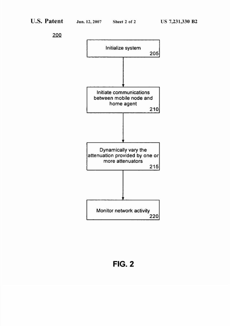
FIG. 2 is a flow chart illustrating a method 200 of
emulating mobile network communications in accordance
with the inventive arrangements disclosed herein. The
method can begin in step 205 where the system is initialized. 30
The wireless nodes, the controller, and the emulator are
brought online and the home agent is initialized. For
example, an application program or other virtual environ
ment that can interact with the mobile nodes can be executed
(1)
The values of G, indicate the gains at the both ends of an
antenna, using the isotropic in dB,. In other words, the signal
strength received at the mobile node is the sUlllllation of all
the gains (S,, G,) minus the propagation loss due to fading
of the signal. This propagation loss depends on the many
characteristics of the terrain and can be empirically defined
as discussed in K. Pahlavan, A. Levesque, Wireless Infor-
mation Networks, John Wiley & Son's, New York (1995),
using different values of Ko and n, depending upon different
terrain conditions at different frequency values.
or instantiated.
One or more mobile nodes can be positioned at a location
(or locations) within communication range of each of the
wireless nodes. For example, a mobile node can be positioned approximately 10 meters from a perimeter established
by the antennas of the wireless nodes. It should be appre
ciated, however, that the mobile nodes can be located at any
suitable distance from the wireless nodes so long as wireless
communications can be exchanged between the mobile node
and the wireless node when little or no attenuation is used.
The experimental values and equations used for signal35
propagation correspond to the modeling for indoor and
micro-cellular environments, as discussed inK. Pahlavan, et
a!., Wireless Information Networks, are illustrated with ref
erence to equation 2. The empirical model indicates that theattenuation is negligible at closer distances from the
40antenna, and quickly, logarithmically decays at certain dis
tances using different values of nand K0
• In this case, 10 and
20 are used in equation 2.
In step 210, communications between the mobile node 45
and the home agent c an be initiated. Fo r example, the mobile
nodes can initiate a file transfer or some other task which can
either be conducted throughout the method 200 or can be
performed in an iterative manner.
(2) A(d) 0,
10 + nlog(d),
20 + 10(n + 1.3)log(d),
d R/100 and d 1.2R
R/100 < d 0.9R
d > 0.9R
In equation 2, d is the distance between the wireless access
point and the mobile node and R is the cell ratio having a
value of 500 meters. A square attenuation model was used to
determine the handoff rate between the wireless nodes as set
In step 215, the attenuation provided by one or more of he 50
attenuators can be dynamically varied. For example, the
controller can decrease the amount of attenuation for one of
the wireless nodes while increasing the amount of attenua
tion with respect to the other wireless nodes. In this manner,
motion of the mobile node can be emulated. As noted, by
varying the rate and amount of attenuation of one or more of
the attenuators, different characteristics of motion such as
the trajectory, speed, and/or acceleration of the mobile node
can be emulated.
55forth in equation 3.
For example, in order to emulate speed, two factors can 60
affect the mobile node: received signal strength and signal
to-noise ratio (SNR). As. the SNR is defined by the Log
(signal/noise), modifYing the signal strength modifies the
SNR. The SNR also can be emulated by adding randonmess
to the attenuation mechanism. Noise can be added in the 65
form of a Gaussian Distribution (Normal Distribution) at a
certain mean and variance. In any case, these factors can be
(3) A(d) 0,
128,
0 d 0.9R
d > 0.9R
Although the attenuators can be varied to provide several
different values of attenuation, acceptable values of attenu
ation can be determined through empirical study. For
example, attenuation can range from approximately 0 to 60
dB or another range so as to prevent wireless access point
signal leakage.

7/30/2019 University of Florida Research Foundation et. al. v. Motorola Mobility
http://slidepdf.com/reader/full/university-of-florida-research-foundation-et-al-v-motorola-mobility 18/19
US 7,231,330 B2
9Accordingly, attenuation of each wireless node can be
varied using the equations specified above to emulate
motion of mobile nodes. As noted, various mobile network
characteristics such as speeds, accelerations, and trajectoriesof the mobile node(s) can be emulated by varying attenua
tion levels. The controller and/or the home agent can be
programmed to vary attenuations to emulate a variety of
different mobile network characteristics. Notably, with
respect to terrain, different terrains also can be emulated by
mapping survey data to settings of the attenuators. As used 10
herein, the term "terrain" can be used to refer to different
natural and/or man-made landscapes. For example, "terrain"
can be used to describe a mountainous landscape, a land
scape having valleys, lakes, and the like. The term further
can refer to urban and/or rural landscapes as well as the 15
landscape of a city in reference to building height, place
ment, and the like.
In step 220, network activity can be monitored and
logged. More particularly, the data throughput at each wire
less node can be tracked over time and compared with the 20
attenuation function as applied to each respective wireless
node. Accordingly, by analyzing the data throughput of each
wireless node, the handoff rate, or the rate at which themobile node leaves the coverage area of one network node
and enters the coverage area of another, can be determined. 25
The signal strength as measured at the mobile node also can
be monitored and compared with the attenuation function
applied to the wireless nodes.
It should be appreciated that other quantities and/or
characteristics can be measured and/or monitored such as 30
the power consumed at the mobile node, the handoff pro
tocol performance, and protocol synchronization. According
to one aspect of the present invention, the performance ofiP
Security (IPSec) protocol and IP in IP tunneling can be
evaluated, for example in the context of Mobile-IP, in 35
conjunction with Virtual Private Networks (VPN) and Layer
2 Tunnel Protocol (L2TP) as secured links over Mobile
wireless Networks. Handoffperformance also can be evaluated.
Additionally, wireless communication characteristics 40
such as authentication and authorization latencies, for
example in the case of IEEE 802.11i, can be emulated. A
Radius Server (authentication server) can be co-located in
one of the wired nodes such that delays can be measured and
wireless authentication also can be emulated. Throughput 45
performance can be monitored for any of a variety of
different communications protocols such as Mobile IP v. 6.
The performance of any higher-layer protocol, including but
not limited to Hypertext Transfer Protocol (HTTP), File
Transfer Protocol (FTP), Universal Plug and Play (UPnP), 50
Simple Mail Transfer Protocol (SMTP), multimedia appli
cations over User Datagram Protocol (UDP) or TCP, and
Layer-2 protocols such as WME and IEEE 802.11e can be
evaluated by simply switching access points.
The present invention also can emulate other wireless 55
communication characteristics such as load and congestion
by limiting the wireless point response time. Network
topologies can be emulated by setting (x,y) coordinates of
the base stations or access points. A mobile node moving
from point (xl, yl ) to (x2, y2) will then intercept a set of 60
access points such that handoff will occur. Depending upon
the velocity equations and the location of each node in an
emulated network topology, an emulated sense of location
can then be acquired. Location-based services can be evalu
ated and tested using the present invention by mapping 65
signal strength to a (x,y) location. Any application at the
mobile node and the emulator can use (x,y) coordinates to
10perform handoff, create virtual foreign agents or wireless
access points, and anticipate resource allocation.
While Mobile IP and Home agent were used as examples,
those skilled in the art will recognize that the inventive
arrangements disclosed herein can be used to emulate any
Layer 2 or 3 Mobility protocol including, but not limited toMobile IP, Mobile IP v. 6, Cellular-IP, and the like. Other
protocols not requiring a Home Agent can also be emulated.
The various references disclosed throughout this applica
tion are hereby incorporated by reference.
The present invention can be realized in hardware, soft
ware, or a combination of hardware and software. The
present invention can be realized in a centralized fashion in
one computer system, or in a distributed fashion where
different elements are spread across several interconnected
computer systems. Any kind of computer system or other
apparatus adapted for carrying out the methods described
herein is suited. A typical combination of hardware and
software can be a general purpose computer system with a
computer program that, when being loaded and executed,
controls the computer system such that it carries out the
methods described herein.
One or more aspects of the present invention also can beembedded in a computer program product, wh ich comprises
all the features enabling the implementation of the methods
described herein, and which when loaded in a computer
system is able to carry out these methods. Computer or
application program in the present context means any
expression, in any language, code or notation, of a set of
instructions intended to cause a system having an informa
tion processing capability to perform a particular function
either directly or after either or both of the following: a)
conversion to another language, code or notation; b) repro
duction in a different material form.
This invention can be embodied in other forms without
departing from the spirit or essential attributes thereof.
Accordingly, reference should be made to the following
claims, rather than to the foregoing specification, as indicating the scope of the invention.
What is claimed is:
1. A system for emulating mobile network communica
tions comprising:
a plurality of fixedly-located wireless network nodes
configured to variably adjust wireless communication
characteristics;
at least one mobile node configured to wirelessly com
municate with selected ones of said plurality of wire
less network nodes;
a network emulator communicatively linked to each of
said plurality of wireless network nodes, said network
emulator configured to emulate attributes of a packet
based wired communications network for simulating
network conditions experienced by said at least one
mobile node in communicating with other nodes
through the wired communications network, the emu
lated attributes comprising at least one of tunable
packet-delay distribution, network congestion, band
width limitation, and packet re-ordering and duplica
tion; and
a controller communicatively linked to each of said
plurality of wireless network nodes, said controller
configured to control the wireless communication char
acteristics of each of said plurality of wireless network
nodes to simulate, without changing operating param
eters of said at least one mobile node, different wireless
communication conditions experienced by said at least
one mobile node in actual operation.

7/30/2019 University of Florida Research Foundation et. al. v. Motorola Mobility
http://slidepdf.com/reader/full/university-of-florida-research-foundation-et-al-v-motorola-mobility 19/19
US 7,231,330 B2
11
2. The system of claim 1, further comprising a home agent
configured to communicatively link the at least one mobile
node to said plurality of wireless network nodes and to a
wired communications network whose attributes are emu
lated by said emulator.
3. The system of claim 1, wherein said wireless commu
nication characteristics include a signal reception sensitivity.
1213. The method of claim 11, wherein wireless communi
cations characteristic includes at least one of signal trans
mission strength, signal-to-noise ratio (SNR), and bit error
rate (BER).
14. The method of claim 11, wherein the wireless network
node comprises a wireless access point, having an antenna
and a variable attenuator.4. The system of claim 1, wherein said wireless commu
nication characteristic includes at least one of signal trans
mission strength, signal-to-noise ratio (SNR), and bit error
rate (BER).
15. The method of claim 14, the wireless network node
10 further comprising a routing device.
5. The system of claim 1, wherein at least one of said
plurality of wireless network nodes includes:
16. The method of claim 14, wherein the wireless network
node is communicatively linked with the home agent
through a network emulator.a wireless access point having an antenna and at least one
variable attenuator; and
a routing device communicatively linking said access
point with said network emulator.
6. The system of claim 5, wherein said controller is
configured to vary an amount of attenuation provided by
said variable attenuator by dynamically adjusting at least 20
one of a signal reception sensitivity and a signal transmis
sion strength of said wireless access point to thereby simu
late motion of said at least one mobile node.
17. The method of claim 14, said step of dynamically15
adjusting at least one wireless communication characteristic
further comprising varying an amount of attenuation pro
vided by the variable attenuator to emulate motion of the
mobile node.
18. The method of claim 17, wherein the variable attenu-
ator comprises a plurality of variable attenuators and further
comprising the step of increasing attenuation provided by
the variable attenuators while simultaneously decreasingattenuation provided by another one of the variable attenu-. The system of claim 6, wherein said variable attenuator
comprises a plurality of variable attenuators; and wherein
the amount of attenuation is varied by increasing attenuation
provided by at least one of said plurality of variable attenu
ators while simultaneously decreasing attenuation provided
25 ators.
by another one of said attenuators.
8. The system of claim 7, wherein said controller dynami- 30
cally adjusts the amount of attenuation provided by at least
two of said attenuators to thereby emulate at least one of
speed, acceleration, and trajectory of said mobile node.
9. The system of claim 6, further comprising:
a data logging component configured to record at least 35
one of a data throughput of at least one of said plurality
of wireless network nodes and a measure of signal
strength received at said mobile node.10. The system of claim 5, wherein said antenna is an
onmi-directional antenna.
11. A method of emulating mobile network communica
tions comprising the steps of:
initiating communications between a home agent and a
mobile node via at least one fixedly-located wireless
network node connected to a controller;
while the mobile node wirelessly communicates with the
40
45
at least one wireless network node, dynamically adjust
ing with the controller at least one wireless communi
cation characteristic of the wireless node to simulate,
without changing operating parameters of the mobile 50
node, different wireless communication conditions
experienced by the mobile node in actual operation;
and
emulating with an emulator connected to the at least one
wireless network node attributes of a packet-based 55
wired communications network to simulate network
conditions experienced by the mobile node in commu
nicating with network-connected nodes through the
wired communications network, the emulated
attributes comprising at least one of tunable packet- 60
delay distribution, network congestion, bandwidth
limitation, and packet re-ordering and duplication.
12. The method of claim 11, wherein the wireless com
munication characteristic includes signal reception sensitiv
ity.
19. The method of claim 18, wherein dynamically adjust
ing the amount of attenuation provided by at least one of the
variable attenuators emulates at least one of speed, accel
eration, and trajectory of the mobile node.
20. A computer readable storage medium for use in
emulating mobile network communications, the storage
medium comprising computer instructions for:
initiating communications between a home agent and a
mobile node via at least one fixedly-located wireless
network node connected to a controller;
while the mobile node wirelessly communicates with the
at least one wireless node, dynamically adjusting withthe controller at least one wireless communication
characteristic of the wireless node to simulate, without
changing operating parameters of the mobile node,
different wireless communication conditions experi
enced by the mobile node in actual operation; and
emulating with an emulator connected to the at least one
wireless network node attributes of a packet-based
wired communications network to simulate network
conditions experienced by the mobile node in commu
nicating with network-connected nodes through the
wired communications network, the emulated
attributes comprising at least one of tunable packet
delay distribution, network congestion, bandwidth
limitation, and packet re-ordering and duplication.21. The computer readable storage medium of claim 20,
wherein the at least one wireless node comprises a plurality
of wireless nodes, and wherein the computer readable stor
age medium further comprises a computer instruction for
increasing attenuation provided by a variable attenuator
communicatively linked to the one of the plurality of wire
less nodes while simultaneously decreasing attenuation pro
vided by another variable attenuator communicatively
linked to another of the plurality of wireless nodes.
* * * * *