
University of Calgary Natural Gas Processing Principles ...oilproduction.net/files/Natural gas...
64
Printed: 25 April 2004 - [Natural Gas Processing Principles and Technology - Part II.doc] University of Calgary Natural Gas Processing Principles and Technology - Part II April 2004 Author: Dr. A.H Younger, P.Eng Revised and Prepared by: Dr Harald F. Thimm & Jason Sullivan Thimm Engineering Inc. 214, 3916 64th Avenue SE Calgary, Alberta T2C 2B4 Tel: (403) 265 - 0792 Web: www.hfthimm.com
Transcript of University of Calgary Natural Gas Processing Principles ...oilproduction.net/files/Natural gas...
Printed: 25 April 2004 - [Natural Gas Processing Principles and Technology - Part II.doc]
University of Calgary
Natural Gas Processing Principles and Technology - Part II
April 2004
Author: Dr. A.H Younger, P.Eng
Revised and Prepared by: Dr Harald F. Thimm & Jason Sullivan
Thimm Engineering Inc. 214, 3916 64th Avenue SE Calgary, Alberta T2C 2B4
Tel: (403) 265 - 0792 Web: www.hfthimm.com
Natural Gas Processing Principles and Technology - Part II University of Calgary April 2004: i (450) Printed: 25 April 2004 - [Natural Gas Processing Principles and Technology - Part II.doc]
Table of Contents Table of Contents .............................................................................................................................. i
List of Figures..................................................................................................................................xi
List of Tables ................................................................................................................................xvii
Purpose of this Document.............................................................................................................xx
Preface ............................................................................................................................................xx
10.0 Compression and Refrigeration..............................................................................10-1
10.1 Compression ..............................................................................................................10-1 10.1.1 Types..........................................................................................................................10-1 10.1.2 Determining Discharge Pressure................................................................................10-1 10.1.3 Work of Compression.................................................................................................10-3 10.1.4 Compression Ratio.....................................................................................................10-7 10.1.5 Ratio of Specific Heats ...............................................................................................10-7 10.1.6 Reciprocating Compressor Capacity ..........................................................................10-8 10.1.7 Rod Loading .............................................................................................................10-11 10.1.8 Specifying Reciprocating Compressors....................................................................10-11 10.1.9 Trouble Shooting Reciprocating Compressors.........................................................10-12 10.1.10 Centrifugal Compressors - HP or W Calculations...............................................10-14 10.1.11 Centrifugal Compressors - General Operating Characteristics ..........................10-15 10.1.12 Centrifugal Compressor Controls .......................................................................10-16 10.1.13 Specifying Centrifugal Compressors ..................................................................10-17 10.1.14 Trouble Shooting Centrifugal Compressors........................................................10-18
10.2 Expansion of Gases .................................................................................................10-18 10.3 Refrigeration.............................................................................................................10-21
10.3.1 General.....................................................................................................................10-21 10.3.2 Thermodynamics......................................................................................................10-23
10.3.2.1 Refrigeration Stages...........................................................................................10-24 10.3.3 Refrigerants Used ....................................................................................................10-26 10.3.4 Power Required........................................................................................................10-26 10.3.5 Equipment Required.................................................................................................10-26 10.3.6 Conditions for a Chilling System...............................................................................10-31 10.3.7 Refrigeration System Checklist ................................................................................10-31
10.4 Example Problems ...................................................................................................10-33 References ..............................................................................................................................10-36
11.0 Economics ................................................................................................................11-1
11.1 Introduction.................................................................................................................11-1 11.2 Economics Indicators .................................................................................................11-1 11.3 What is Considered a Good Investment.....................................................................11-1 11.4 Capital Costs ..............................................................................................................11-3
11.4.1 Preliminary Feasibility Estimate..................................................................................11-3
Natural Gas Processing Principles and Technology - Part II April 2004: ii (450) University of Calgary
Printed: 25 April 2004 - [Natural Gas Processing Principles and Technology - Part II.doc]
11.4.2 Preliminary Budget Estimate...................................................................................... 11-3 11.4.3 Appropriation or Budget Estimate ............................................................................ 11-19 11.4.4 The Definitive or Detailed Estimate.......................................................................... 11-20 11.4.5 Accuracy of Estimate ............................................................................................... 11-24
11.4.5.1 Known Cost ........................................................................................................ 11-24 11.4.5.2 Known Uncertainty ............................................................................................. 11-24 11.4.5.3 Unknown Uncertainty ......................................................................................... 11-24
11.4.6 Final Estimated Contingency Calculation................................................................. 11-25 11.5 Operating Costs ....................................................................................................... 11-27 11.6 Prices for Products................................................................................................... 11-30 11.7 Information Required to Evaluate a Project ............................................................. 11-30 11.8 Actual Economic Calculations.................................................................................. 11-32 References .............................................................................................................................. 11-33 Reading List ............................................................................................................................ 11-33
12.0 Producing of Gas Well............................................................................................. 12-1
12.1 Introduction ................................................................................................................ 12-1 12.2 Gas Well Equipment .................................................................................................. 12-1 12.3 Well Testing ............................................................................................................... 12-1 12.4 Types of Tests............................................................................................................ 12-6
12.4.1 Conventional Back Pressure Test.............................................................................. 12-6 12.4.2 Isochronal Test........................................................................................................... 12-7 12.4.3 Modified Isochronal Test ............................................................................................ 12-7 12.4.4 Modification of Previously Discussed Tests ............................................................... 12-7
12.5 Other Data Required During a Test ........................................................................... 12-7 12.6 Sampling of Gas During a Test .................................................................................. 12-8
12.6.1 Recommended Gas Well Testing .............................................................................. 12-8 12.6.2 Determining the Composition..................................................................................... 12-9
12.7 The Use of the Data Obtained ................................................................................. 12-11 12.8 Problems.................................................................................................................. 12-13 References .............................................................................................................................. 12-14
13.0 Field Processing of Gas .......................................................................................... 13-1
13.1 Introduction ................................................................................................................ 13-1 13.2 Heating....................................................................................................................... 13-1
13.2.1 Heaters....................................................................................................................... 13-1 13.2.2 Hot Water Tracing...................................................................................................... 13-4 13.2.3 General ...................................................................................................................... 13-4 13.2.4 Design........................................................................................................................ 13-4 13.2.5 Line Heaters............................................................................................................... 13-7
13.3 Water Removal or Dehydration.................................................................................. 13-7 13.3.1 Glycol Treaters........................................................................................................... 13-7 13.3.2 CaCl2 for Water Removal........................................................................................... 13-9 13.3.3 Specifications ............................................................................................................. 13-9
13.4 Combining the Free Water with Chemicals.............................................................. 13-10
Natural Gas Processing Principles and Technology - Part II University of Calgary April 2004: iii (450) Printed: 25 April 2004 - [Natural Gas Processing Principles and Technology - Part II.doc]
13.5 Special Methods.......................................................................................................13-10 13.5.1 Short Cycle Units......................................................................................................13-10 13.5.2 Low Temperature Dewpoints or High Water Content Gases ...................................13-10
13.6 Problems ..................................................................................................................13-11 References ..............................................................................................................................13-14
14.0 Transporting of Fluids to the Plant.........................................................................14-1
14.1 Introduction.................................................................................................................14-1 14.2 Determination of Size .................................................................................................14-1
14.2.1 Design Flow................................................................................................................14-1 14.2.2 Allowable Pressure Drop............................................................................................14-4 14.2.3 Calculation of Pressure Drop......................................................................................14-5 14.2.4 Two Phase Flow.........................................................................................................14-7
14.3 Codes .......................................................................................................................14-15 14.4 Typical Pipeline Project ............................................................................................14-15
14.4.1 Design ......................................................................................................................14-15 14.4.2 Protection of Pipe .....................................................................................................14-20 14.4.3 Route Selection ........................................................................................................14-21 14.4.4 Pipe. Valve and Fitting Ordering...............................................................................14-21 14.4.5 Survey and Right of Way Acquisitions......................................................................14-21 14.4.6 Pipeline Construction ...............................................................................................14-22 14.4.7 Pressure Testing ......................................................................................................14-22 14.4.8 Putting the Pipeline into Service...............................................................................14-22 14.4.9 Pressuring Up...........................................................................................................14-23
14.5 PROBLEMS .............................................................................................................14-23 References ..............................................................................................................................14-24 Reading List.............................................................................................................................14-24
15.0 Receiving Gas at a Plant..........................................................................................15-1
15.1 Introduction.................................................................................................................15-1 15.2 Function of Inlet Separators .......................................................................................15-1 15.3 Particle Size ...............................................................................................................15-1 15.4 Types of Separators ...................................................................................................15-1 15.5 Description of Common Separators ...........................................................................15-2
15.5.1 Vertical Separator.......................................................................................................15-3 15.5.2 Horizontal Separator ..................................................................................................15-3 15.5.3 Spherical Separator....................................................................................................15-4 15.5.4 Cyclone Separator......................................................................................................15-5
15.6 Separation Theory......................................................................................................15-6 15.6.1 Momentum .................................................................................................................15-6 15.6.2 Gravity Settling ...........................................................................................................15-6 15.6.3 Gravity Settling - Limiting Conditions..........................................................................15-8
15.6.3.1 Newton's Law .......................................................................................................15-8 15.6.3.2 Stoke's Law ..........................................................................................................15-8 15.6.3.3 Coalescing............................................................................................................15-9
Natural Gas Processing Principles and Technology - Part II April 2004: iv (450) University of Calgary
Printed: 25 April 2004 - [Natural Gas Processing Principles and Technology - Part II.doc]
15.6.3.4 Separator Design and Construction ..................................................................... 15-9 15.6.3.5 Parts of a Separator ............................................................................................. 15-9
15.7 Design of the Separator ........................................................................................... 15-11 15.7.1 Allowable Velocity .................................................................................................... 15-11 15.7.2 Vessel Height or Length........................................................................................... 15-13
15.8 Filter Separators....................................................................................................... 15-17 15.9 Other Types of Impingement Separators ................................................................. 15-18 15.10 Problems.................................................................................................................. 15-18 References .............................................................................................................................. 15-20
16.0 Sour Gas Treating.................................................................................................... 16-1
16.1 What is Sour Gas?..................................................................................................... 16-1 16.2 Review of Processes.................................................................................................. 16-1
16.2.1 Dry Box Treating ........................................................................................................ 16-5 16.2.2 Caustic Treating......................................................................................................... 16-5 16.2.3 Amine Treating........................................................................................................... 16-5 16.2.4 Hot Potassium Carbonate .......................................................................................... 16-5 16.2.5 Sulphinol .................................................................................................................... 16-5 16.2.6 Diglycol Amine ........................................................................................................... 16-6 16.2.7 Other Chemicals ........................................................................................................ 16-6 16.2.8 Miscellaneous Processes........................................................................................... 16-6
16.3 Process Descriptions ................................................................................................. 16-9 16.3.1 Iron Sponge................................................................................................................ 16-9 16.3.2 Caustic Treating......................................................................................................... 16-9 16.3.3 Amine Treating........................................................................................................... 16-9 16.3.4 The MEA Process ...................................................................................................... 16-9
16.3.4.1 Process Description ............................................................................................. 16-9 16.3.4.2 Design Criteria.................................................................................................... 16-10 16.3.4.3 Operations.......................................................................................................... 16-13 16.3.4.4 Special Notes ..................................................................................................... 16-14 16.3.4.5 Summary of Process .......................................................................................... 16-14
16.3.5 The DEA Process..................................................................................................... 16-14 16.3.5.1 Process Description ...........................................................................................16-15 16.3.5.2 Design Criteria.................................................................................................... 16-15 16.3.5.3 Operations.......................................................................................................... 16-16
16.3.6 The MDEA Process.................................................................................................. 16-16 16.3.7 Hindered Amines...................................................................................................... 16-17 16.3.8 Diglycolamine........................................................................................................... 16-17 16.3.9 General .................................................................................................................... 16-17 16.3.10 Hot Potassium Carbonate Treating .................................................................... 16-18
16.3.10.1 Process Description ..................................................................................... 16-19 16.3.10.2 Design Consideration................................................................................... 16-19 16.3.10.3 Operations ................................................................................................... 16-21 16.3.10.4 Special Notes............................................................................................... 16-21
16.3.11 Giammaro-Vetrecoke Process ........................................................................... 16-21
Natural Gas Processing Principles and Technology - Part II University of Calgary April 2004: v (450) Printed: 25 April 2004 - [Natural Gas Processing Principles and Technology - Part II.doc]
16.3.12 The Sulphinol Process........................................................................................16-21 16.3.12.1 Process Description .....................................................................................16-22 16.3.12.2 Design Criteria.............................................................................................16-22 16.3.12.3 Operations....................................................................................................16-23 16.3.12.4 Special Notes ...............................................................................................16-23
16.4 Other Solvents..........................................................................................................16-24 16.4.1 Propylene Carbonate (Fluor Solvent Process) .........................................................16-24
16.4.1.1 Special Notes......................................................................................................16-25 16.4.2 Selexol and Other Similar Solvents ..........................................................................16-25 16.4.3 Purisol Process ........................................................................................................16-25 16.4.4 Miscellaneous Processes.........................................................................................16-25
16.5 Selection of a Sweetening Process..........................................................................16-29 16.5.1 Specific Selection Procedure ...................................................................................16-30 16.5.2 Influence of Impurities ..............................................................................................16-33
16.6 H2S Scavenging Processes......................................................................................16-34 16.7 Problems ..................................................................................................................16-35 References ..............................................................................................................................16-37 Reading List.............................................................................................................................16-38
17.0 Dewpoint Control (Hydrocarbon and Water) .........................................................17-1
17.1 What Are We Trying to Do?........................................................................................17-1 17.2 The Chilling Process ..................................................................................................17-1
17.2.1 Process Description ...................................................................................................17-1 17.2.2 Design Criteria............................................................................................................17-3 17.2.3 Operations..................................................................................................................17-3
17.2.3.1 Glycol Losses .......................................................................................................17-3 17.2.3.2 Glycol Foaming.....................................................................................................17-3
17.3 The Adsorption Process .............................................................................................17-4 17.3.1 Adsorbents .................................................................................................................17-4 17.3.2 Process Description ...................................................................................................17-4 17.3.3 Design Considerations ...............................................................................................17-5 17.3.4 Operations..................................................................................................................17-6
17.4 Dehydration Processes Only......................................................................................17-7 17.4.1 Glycol Dehydration .....................................................................................................17-7
17.4.1.1 Process Description..............................................................................................17-7 17.4.1.2 Design Data..........................................................................................................17-7 17.4.1.3 Operating Problems and Operating Data .............................................................17-8
17.4.2 Long Cycle Adsorption .............................................................................................17-10 17.4.2.1 Solid Desiccant Drying........................................................................................17-10 17.4.2.2 What Happens in Adsorption Tower? .................................................................17-10 17.4.2.3 Regenerating of an Adsorption ...........................................................................17-11 17.4.2.4 Process Description............................................................................................17-12 17.4.2.5 Design Data........................................................................................................17-12 17.4.2.6 Other Criteria ......................................................................................................17-12 17.4.2.7 Operating Problems............................................................................................17-12

Natural Gas Processing Principles and Technology - Part II April 2004: vi (450) University of Calgary
Printed: 25 April 2004 - [Natural Gas Processing Principles and Technology - Part II.doc]
17.5 The Absorption Process........................................................................................... 17-12 17.5.1 Process Description ................................................................................................. 17-13 17.5.2 Design Criteria ......................................................................................................... 17-13 17.5.3 Operations................................................................................................................ 17-15
References .............................................................................................................................. 17-15
18.0 Fractionation ............................................................................................................ 18-1
18.1 Introduction ................................................................................................................ 18-1 18.2 Tower Sizing .............................................................................................................. 18-2
18.2.1 Tower Diameter.......................................................................................................... 18-2 18.2.2 Tower Height.............................................................................................................. 18-2 18.2.3 Typical Data on Separations ...................................................................................... 18-7 18.2.4 Controlling a Tower .................................................................................................... 18-7 18.2.5 Condensate Stabilization - A Typical Fractionation Process...................................... 18-8 18.2.6 Example of a Fractionation System ........................................................................... 18-9
18.3 Problems.................................................................................................................. 18-12 References .............................................................................................................................. 18-13
19.0 NGL Recovery Processes ....................................................................................... 19-1
19.1 Introduction ................................................................................................................ 19-1 19.2 Processes .................................................................................................................. 19-1
19.2.1 Refrigerated Absorption ............................................................................................. 19-2 19.2.1.1 Description ........................................................................................................... 19-2 19.2.1.2 Design Criteria...................................................................................................... 19-2 19.2.1.3 Operations............................................................................................................ 19-8
19.2.2 Adsorption.................................................................................................................. 19-8 19.2.2.1 Process Description ............................................................................................. 19-8 19.2.2.2 Design Data.......................................................................................................... 19-9 19.2.2.3 Operation............................................................................................................ 19-10
19.2.3 Low Temperature Refrigeration (Cryogenics or Expander Plant) ............................ 19-10 19.2.3.1 Process Description ...........................................................................................19-10 19.2.3.2 Process Design .................................................................................................. 19-12 19.2.3.3 Operations.......................................................................................................... 19-13
19.3 Problems.................................................................................................................. 19-15 References .............................................................................................................................. 19-18 Reading List ............................................................................................................................ 19-18
20.0 Sulphur Recovery .................................................................................................... 20-1
20.1 Processes .................................................................................................................. 20-1 20.2 MODIFIED CLAUS PROCESS.................................................................................. 20-3
20.2.1 Equilibrium Conversion .............................................................................................. 20-7 20.2.2 Thermodynamic Data................................................................................................. 20-8 20.2.3 Reaction Furnace....................................................................................................... 20-9
20.2.3.1 Furnace Chemistry ............................................................................................. 20-10 20.2.3.2 Furnace Conversion ........................................................................................... 20-11 20.2.3.3 Process and Mechanical Considerations ........................................................... 20-16
Natural Gas Processing Principles and Technology - Part II University of Calgary April 2004: vii (450) Printed: 25 April 2004 - [Natural Gas Processing Principles and Technology - Part II.doc]
20.2.3.4 Gas Cooling & Sulphur Condensation ................................................................20-16 20.2.4 Waste Heat Boiler ....................................................................................................20-16 20.2.5 Converters................................................................................................................20-17
20.2.5.1 Design ................................................................................................................20-17 20.2.5.2 Modified-Claus Catalysts ....................................................................................20-17 20.2.5.3 Deactivation and Catalyst Management .............................................................20-19 20.2.5.4 Temperature Profiles ..........................................................................................20-21 20.2.5.5 Design Criteria ....................................................................................................20-24
20.2.6 Sulphur Condensers.................................................................................................20-25 20.2.7 Sulphur Fog and Mist ...............................................................................................20-26 20.2.8 Coalescers and Mist Eliminators ..............................................................................20-26 20.2.9 Incinerator and Stack ...............................................................................................20-27 20.2.10 Other Design Considerations..............................................................................20-29 20.2.11 OPERATIONS ....................................................................................................20-29 20.2.12 Plant Stability ......................................................................................................20-30 20.2.13 Operating Problems............................................................................................20-34 20.2.14 Other Reactions Occurring in Process ...............................................................20-34 20.2.15 Emergencies.......................................................................................................20-34
20.2.15.1 Hydrocarbon Carryover ................................................................................20-34 20.2.15.2 Flame Failure ...............................................................................................20-35
20.3 Storing and Loading of Sulphur................................................................................20-35 20.3.1 Introduction...............................................................................................................20-35 20.3.2 Sulphur Block Storage..............................................................................................20-36 20.3.3 Sulphur Forming.......................................................................................................20-37
20.4 Sulphur Plant Tail Gas Clean-Up Processes............................................................20-40 20.4.1 Introduction...............................................................................................................20-40 20.4.2 Processes.................................................................................................................20-41
20.4.2.1 The Sulfreen Process .........................................................................................20-44 20.4.2.2 The Amoco CBA Process ...................................................................................20-46 20.4.2.3 The IFP Process.................................................................................................20-48 20.4.2.4 The SCOT Process (Shell Claus of f Gas Treating Process) .............................20-49 20.4.2.5 The Beavon Process ..........................................................................................20-52 20.4.2.6 The Pritchard Clean-air Process.........................................................................20-54 20.4.2.7 The Wellman-Lord Process ................................................................................20-54 20.4.2.8 The Lo-Cat Process............................................................................................20-55 20.4.2.9 The MCRC Process............................................................................................20-57 20.4.2.10 Other Processes...........................................................................................20-57
20.5 Problems ..................................................................................................................20-58 References ..............................................................................................................................20-60
21.0 Special Situations ....................................................................................................21-1
21.1 Solution Gas Recovery...............................................................................................21-1 21.2 Cycling........................................................................................................................21-1 21.3 Load Levelling ............................................................................................................21-2 21.4 Enhanced Oil Recovery Projects (EOR Projects).......................................................21-3
Natural Gas Processing Principles and Technology - Part II April 2004: viii (450) University of Calgary
Printed: 25 April 2004 - [Natural Gas Processing Principles and Technology - Part II.doc]
21.5 Mercaptan Removal ................................................................................................... 21-4 21.6 Gas Processes........................................................................................................... 21-9 21.7 Substitute Natural Gas............................................................................................. 21-11
21.7.1 What is SNG? .......................................................................................................... 21-11 21.7.2 How is SNG Made?.................................................................................................. 21-11 21.7.3 Plants in Operation................................................................................................... 21-12 21.7.4 Process Description ................................................................................................. 21-13
21.7.4.1 Liquid Hydrocarbons up to and including naphthas ........................................... 21-13 21.7.4.2 Heavier Liquid Hydrocarbon Feed Stocks.......................................................... 21-16 21.7.4.3 Coal as Feed Stock ............................................................................................ 21-17
21.7.5 Coal Type Process................................................................................................... 21-19 21.7.6 Lurgi Process ........................................................................................................... 21-20 21.7.7 CO2 Acceptor Process .............................................................................................21-23 21.7.8 Hygas Process......................................................................................................... 21-24 21.7.9 The Bi-Gas Process................................................................................................. 21-26 21.7.10 Texaco Process.................................................................................................. 21-26 21.7.11 Westinghouse Process....................................................................................... 21-26
21.8 General Comments .................................................................................................. 21-26 References .............................................................................................................................. 21-27
22.0 Environmental Considerations in Natural Gas Processing ................................. 22-1
22.1 Introduction ................................................................................................................ 22-1 22.2 LEGAL REGULATIONS (Legislative Controls) .......................................................... 22-1 22.3 Air Pollution Control ................................................................................................... 22-8
22.3.1 Process Operations.................................................................................................... 22-8 22.3.2 Design of Stacks ........................................................................................................ 22-9 22.3.3 Other Considerations ............................................................................................... 22-14 22.3.4 Regulating Smoke Production.................................................................................. 22-15 22.3.5 Elimination of Smoke in Flaring Waste Gases ......................................................... 22-15
22.3.5.1 Steam Injection................................................................................................... 22-16 22.3.5.2 Air Injection......................................................................................................... 22-16
22.3.6 NOx Concentrations in the Atmosphere................................................................... 22-18 22.4 Treatment of Aqueous Wastes from Gas Plants...................................................... 22-19
22.4.1 Effluent Treatment Requirements ............................................................................22-21 22.4.2 Disposal Methods..................................................................................................... 22-21
22.4.2.1 Subsurface Injection........................................................................................... 22-22 22.4.2.2 Evaporation ........................................................................................................ 22-31 22.4.2.3 Release to Surface Streams .............................................................................. 22-31
22.4.3 Water Quality Parameters........................................................................................ 22-31 22.4.3.1 Chemical Oxygen Demand (C.O.D.) .................................................................. 22-31 22.4.3.2 Suspended Solids (S.S.) .................................................................................... 22-32 22.4.3.3 Sulphides............................................................................................................ 22-32 22.4.3.4 Ammonia Nitrogen.............................................................................................. 22-32 22.4.3.5 Oil and Grease ................................................................................................... 22-32 22.4.3.6 Threshold Odour Number (T.O.N.)..................................................................... 22-36
Natural Gas Processing Principles and Technology - Part II University of Calgary April 2004: ix (450) Printed: 25 April 2004 - [Natural Gas Processing Principles and Technology - Part II.doc]
22.4.3.7 pH 22-36 22.5 OTHER POLLUTION CONSIDERATIONS ..............................................................22-36
22.5.1.1 Disposal of Spent Amine ....................................................................................22-36 22.5.1.2 Disposal of Spent Caustic...................................................................................22-36 22.5.1.3 Thermal Pollution................................................................................................22-36 22.5.1.4 Liquid Disposal from Gas Well............................................................................22-36 22.5.1.5 Soil Pollution.......................................................................................................22-36
22.6 Noise Pollution .........................................................................................................22-37 22.7 Final Draft Noise Guidelines ERCB Noise Committee .............................................22-39 22.8 Problems ..................................................................................................................22-43 References ..............................................................................................................................22-45
23.0 Cryogenics................................................................................................................23-1
23.1 What is Cryogenics? ..................................................................................................23-1 23.2 General.......................................................................................................................23-1 23.3 Physical Data .............................................................................................................23-1 23.4 Overall LNG Production .............................................................................................23-4 23.5 Liquefaction Processes ..............................................................................................23-7
23.5.1 Expander Cycle ..........................................................................................................23-7 23.5.2 Cooling Curves...........................................................................................................23-8 23.5.3 Cascade Liquefaction Cycle.....................................................................................23-14 23.5.4 Air Products Propane Precooled Mixed Refrigerant Process...................................23-16 23.5.5 Technip Precooled Tealarc Process.........................................................................23-17 23.5.6 Special Equipment in the Liquefaction Process .......................................................23-18
23.5.6.1 Compressors & Drivers.......................................................................................23-18 23.5.6.2 Heat Exchangers ................................................................................................23-19
23.5.7 Final Flash or Sub-cooling........................................................................................23-20 23.5.8 Comparison of LNG Processes................................................................................23-21 23.5.9 Power Required for the Process...............................................................................23-22 23.5.10 Optimization of Work Required...........................................................................23-25
23.6 Storage.....................................................................................................................23-25 23.6.1 Above-Ground Double Walled Metal Tanks .............................................................23-31
23.6.1.1 Prestressed Concrete Tanks ..............................................................................23-34 23.7 Terminal Design .......................................................................................................23-38 23.8 LNG Marine Transportation......................................................................................23-38
23.8.1 Freestanding Cargo Tanks.......................................................................................23-39 23.8.2 Membrane Tanks .....................................................................................................23-40 23.8.3 Fleet Size .................................................................................................................23-41
References ..............................................................................................................................23-44 Reading List.............................................................................................................................23-44
24.0 Gas Handling and Processing Summary ...............................................................24-1
24.1 Introduction.................................................................................................................24-1
Appendix 2.0 Natural Gas Processing Principles and Technology - Part II ........................5
List of Key Terms .............................................................................................................................6
Natural Gas Processing Principles and Technology - Part II April 2004: x (450) University of Calgary
Printed: 25 April 2004 - [Natural Gas Processing Principles and Technology - Part II.doc]
List of Example Problems ............................................................................................................... 6
List of Equations.............................................................................................................................. 7
List of Reactions .............................................................................................................................. 9
Reference of Key Equations ......................................................................................................... 11
Natural Gas Processing Principles and Technology - Part II University of Calgary April 2004: xi (450) Printed: 25 April 2004 - [Natural Gas Processing Principles and Technology - Part II.doc]
List of Figures Figure 10.1: Compressor Discharge System ...............................................................................10-1
Figure 10.2: Types of Compressors .............................................................................................10-2
Figure 10.3: Compressor Coverage Chart ...................................................................................10-3
Figure 10.4: Capacity and Power of Reciprocating Compressors................................................10-9
Figure 10.5: Head Capacity Curve for Centrifugal Compressors ...............................................10-15
Figure 10.6: Compressor Head ..................................................................................................10-16
Figure 10.7: Typical Performance Map of Centrifugal Compressors .........................................10-17
Figure 10.8: Simple Expander....................................................................................................10-19
Figure 10.9: Entropy and Enthalpy Plot......................................................................................10-20
Figure 10.10: Finding the Amount of Condensed Liquid ............................................................10-21
Figure 10.11: Typical Refrigeration System ...............................................................................10-22
Figure 10.12: Refrigeration Thermodynamic Cycle....................................................................10-23
Figure 10.13: One-Stage Refrigeration System .........................................................................10-24
Figure 10.14: Two-Stage Refrigeration System .........................................................................10-25
Figure 10.15: Three-Stage Refrigeration System.......................................................................10-26
Figure 10.16: Single-Stage Propane Refrigeration System .......................................................10-28
Figure 10.17: Two-Stage Propane Refrigeration System...........................................................10-29
Figure 10.18: Three-Stage Propane Refrigeration System ........................................................10-30
Figure 10.19: HP Required for Different Condensing System....................................................10-33
Figure 11.1: Estimate Accuracy ...................................................................................................11-4
Figure 11.2: Categories of Estimates ...........................................................................................11-5
Figure 11.3: Gas Sweetening Unit Costs .....................................................................................11-7
Figure 11.4: Claus Sulphur Exclusive of Tail Gas Units...............................................................11-8
Figure 11.5: Dew Point Control Units ...........................................................................................11-9
Figure 11.6: Plant Glycol Dehydration Unit ................................................................................11-10
Figure 11.7: Fractionation Vs Feed BPD....................................................................................11-11
Figure 11.8: Compressor Installations – Total Project Costs .....................................................11-12
Figure 11.9: Total Installed Costs for Uninsulated Pipeline Construction ..................................11-13
Figure 11.10: Wellsite Costs ......................................................................................................11-14
Figure 11.11: Turbo Expander Units (Costs)..............................................................................11-15
Figure 11.12: Operations Cost Profile ........................................................................................11-26
Figure 12.1: Bottom Hole Equipment ...........................................................................................12-3

Natural Gas Processing Principles and Technology - Part II April 2004: xii (450) University of Calgary
Printed: 25 April 2004 - [Natural Gas Processing Principles and Technology - Part II.doc]
Figure 12.2: Typical Wellhead ..................................................................................................... 12-4
Figure 12.3: Back Pressure Equation Plot ................................................................................... 12-6
Figure 12.4: Deliverability Curves ................................................................................................ 12-8
Figure 12.5: Flow through Gas Composition Test Equipment ................................................... 12-10
Figure 12.6: Typical Wellhead Temperature Curve ................................................................... 12-13
Figure 13.1: Typical Heater Installation ....................................................................................... 13-2
Figure 13.2: Options for Hydrate Control ..................................................................................... 13-3
Figure 13.3: Glycol Dehydrator Components............................................................................... 13-6
Figure 13.4: Typical Dehydrator................................................................................................... 13-9
Figure 13.5: CaCl2 Dehydrator..................................................................................................... 13-9
Figure 13.6: Example Solid Desiccant Dehydrator Twin Tower System.................................... 13-11
Figure 14.1: Typical Gathering System........................................................................................ 14-3
Figure 14.2: Recommended Friction Factors for Gas Flow ......................................................... 14-6
Figure 14.3: Flanigan Efficiency Factor ..................................................................................... 14-10
Figure 14.4: Flanigan Efficiency Factor (Metric) ........................................................................ 14-11
Figure 14.5: Elevation Correction Factor ................................................................................... 14-12
Figure 14.6: Elevation Correction Factor (Metric) ...................................................................... 14-13
Figure 14.7: Typical Pipeline Project .........................................................................................14-19
Figure 15.1: Gravity Settling Laws and Particle Characteristics .................................................. 15-2
Figure 15.2: Vertical Separator .................................................................................................... 15-3
Figure 15.3: Horizontal Separator................................................................................................ 15-4
Figure 15.4: Spherical Separator ................................................................................................. 15-5
Figure 15.5: Cyclone Separator ................................................................................................... 15-6
Figure 15.6: Forces on Liquid Droplet in Gas Stream.................................................................. 15-7
Figure 15.7: Drag Coefficient of Rigid Spheres ........................................................................... 15-8
Figure 15.8: Gas-Liquid Separators........................................................................................... 15-10
Figure 15.9: Recycling Action in Centrifugal Separator ............................................................. 15-11
Figure 15.10: Disengaging Space Vertical Separation .............................................................. 15-12
Figure 15.11: Using Half Disengaging Space Horizontal Separation ........................................ 15-13
Figure 15.12: Liquid Hold-up in Pipelines .................................................................................. 15-15
Figure 15.13: Example Horizontal Filter Separator .................................................................... 15-18
Figure 16.1: Typical MEA Sweetening Process......................................................................... 16-11
Figure 16.2: Typical MEA Contactor Temperature Profile ......................................................... 16-12
Figure 16.3: Steam Requirements for MEA Solutions per Fitzgerald and Richardson .............. 16-13
Figure 16.4: DEA Amine Sweetening Process .......................................................................... 16-18
Natural Gas Processing Principles and Technology - Part II University of Calgary April 2004: xiii (450) Printed: 25 April 2004 - [Natural Gas Processing Principles and Technology - Part II.doc]
Figure 16.5: Reaction Rate K2CO3 Process ...............................................................................16-19
Figure 16.6: Typical Hot Carbonate Flow Sheet ........................................................................16-20
Figure 16.7: Tray Calculations for CO2 Absorber .......................................................................16-20
Figure 16.8: The Sulphinol Sweetening Process .......................................................................16-24
Figure 16.9: Propylene Carbonate Flow Sheet ..........................................................................16-25
Figure 16.10: Stretford Process .................................................................................................16-27
Figure 16.11: Lo-Cat Sulphur Recovery Process.......................................................................16-28
Figure 16.12: C3+ Content of Gases Treated by DEA and Sulphinol..........................................16-29
Figure 16.13: CO2 Removal .......................................................................................................16-32
Figure 16.14: H2S Removal........................................................................................................16-32
Figure 16.15: H2S and CO2 Removal .........................................................................................16-32
Figure 16.16: Selective H2S Removal ........................................................................................16-32
Figure 17.1: The Chilling Process ................................................................................................17-2
Figure 17.2: Adsorbing Process ...................................................................................................17-5
Figure 17.3: Adsorbing of C5 & C6 ................................................................................................17-6
Figure 17.4: Glycol Dehydration...................................................................................................17-9
Figure 17.5: Equilibrium Capacity Solid Adsorbents ....................................................................17-9
Figure 17.6: Commercial Operation of Solid Desiccants Manufacturers Data ...........................17-10
Figure 17.7: Dewpoint Values Out of a Desiccant Bed ..............................................................17-11
Figure 17.8: Regeneration of a Desiccant..................................................................................17-11
Figure 17.9: The Absorption Process.........................................................................................17-14
Figure 18.1: Typical Fractionating Tower .....................................................................................18-2
Figure 18.2: Tower Capacity Correlation......................................................................................18-5
Figure 18.3: Tower Sizing Nomograph.........................................................................................18-6
Figure 18.4: Typical Control System ............................................................................................18-8
Figure 18.5: Stabilizer Flow Sheet ...............................................................................................18-9
Figure 18.6: Straight Through Processing Scheme – Scheme 1 ...............................................18-10
Figure 18.7: Revised Processing Scheme – Scheme 2 .............................................................18-10
Figure 18.8: Second Revision to Processing Scheme – Scheme 3 ...........................................18-11
Figure 19.1: Refrigerated Lean Oil System ..................................................................................19-2
Figure 19.2: % Absorbed Vs Absorption Factor ...........................................................................19-7
Figure 19.3: Adsorption Process ..................................................................................................19-9
Figure 19.4: Adsorption of C5 and C6 .........................................................................................19-10
Figure 19.5: Expander Process..................................................................................................19-11
Figure 19.6: Pressure Temperature Diagram Expander Plant ...................................................19-13
Natural Gas Processing Principles and Technology - Part II April 2004: xiv (450) University of Calgary
Printed: 25 April 2004 - [Natural Gas Processing Principles and Technology - Part II.doc]
Figure 19.7: Feed Condensation Scheme ................................................................................. 19-14
Figure 19.8: Residue Gas Condensation Scheme..................................................................... 19-15
Figure 20.1: Claus Sulphur Plant ................................................................................................. 20-3
Figure 20.2: Direct Heat Methods ................................................................................................ 20-4
Figure 20.3: Indirect Heat Methods.............................................................................................. 20-5
Figure 20.4: Modified Claus Process Configurations................................................................... 20-7
Figure 20.5: Special Versions of the Claus Process.................................................................... 20-7
Figure 20.6: Equilibrium Conversion of H2S to Sulphur ............................................................... 20-9
Figure 20.7: Reaction Furnace Conversion Versus Acid Gas Bypass Fraction......................... 20-12
Figure 20.8: Furnace Conversion Versus Acid Gas Bypass Fraction (Measured)..................... 20-14
Figure 20.9: Measured Reaction Furnace Unit Conversions ..................................................... 20-15
Figure 20.10: Typical Converter................................................................................................. 20-17
Figure 20.11: Modified-Claus Reaction Over Bauxite After Specified Hours of Continuous Operation ................................................................................................................................. 20-19
Figure 20.12: Converter Temperature Profiles Typical Of Various States Of Catalyst Deactivation................................................................................................................................................. 20-23
Figure 20.13: Practicable Capability the Modified - Claus Process as a Function of Acid Gas Composition ............................................................................................................................. 20-25
Figure 20.14: Incinerator and Stack...........................................................................................20-28
Figure 20.15: Efficiency Loss as a Function of Excess Reaction Air (Modified-Claus Process) 20-30
Figure 20.16: Trace of Actual Recording of Sulphur Plant Recovery Efficiency (Automatic Air to Acid Gas Ratio Control) ........................................................................................................... 20-31
Figure 20.17: Typical Sulphur Slating Process .......................................................................... 20-37
Figure 20.18: Sulphur Prilling Facility ........................................................................................ 20-38
Figure 20.19: Sulphur Forming Facility Schematic .................................................................... 20-39
Figure 20.20: Sulphur Recovery Requirements for Alberta Sour Gas Plants - August 1988..... 20-40
Figure 20.21: Tail Gas Clean-up Processes .............................................................................. 20-43
Figure 20.22: Sulfreen Flow Diagram ........................................................................................ 20-45
Figure 20.23: Amoco CBA Flow Diagram .................................................................................. 20-47
Figure 20.24: IFP Process ......................................................................................................... 20-49
Figure 20.25: SCOT Process..................................................................................................... 20-51
Figure 20.26: Beavon Process................................................................................................... 20-53
Figure 20.27: Lo-Cat Process .................................................................................................... 20-56
Figure 20.28: Four Converter MCRC Process........................................................................... 20-57
Figure 21.1: Liquid Recovery with Blowdown .............................................................................. 21-2
Figure 21.2: Pressure Drop - Retrograde Condensation ............................................................. 21-2
Natural Gas Processing Principles and Technology - Part II University of Calgary April 2004: xv (450) Printed: 25 April 2004 - [Natural Gas Processing Principles and Technology - Part II.doc]
Figure 21.3: Load Levelling Process Scheme..............................................................................21-3
Figure 21.4: Moleculer Sieve Treating & Drying...........................................................................21-6
Figure 21.5: Regenerative Caustic...............................................................................................21-7
Figure 21.6: Merox Extractor........................................................................................................21-8
Figure 21.7: Cost of SNG Manufacturing 1971 ..........................................................................21-12
Figure 21.8: The CRG Double Methanation SNG Process ........................................................21-15
Figure 21.9: The CRG Hydrogasification Process .....................................................................21-15
Figure 21.10: The Fluid-bed Hydrogenator Based SNG Process ..............................................21-17
Figure 21.11: Coal Gasification Diagram ...................................................................................21-19
Figure 21.12: Coal Contents ......................................................................................................21-20
Figure 21.13: Lurgi Gasifier........................................................................................................21-22
Figure 21.14: Simplified Flow Diagram of the Lurgi Process .....................................................21-23
Figure 21.15: CO2 Accept Process - Gasification Section..........................................................21-24
Figure 21.16: Flow Diagram of IGT Hygas Process...................................................................21-25
Figure 22.1: Sulphur Recovery Requirements for Alberta Sour Gas Plants - August 1988 .........22-9
Figure 22.2: Atmospheric Transport And Diffusion Studies .......................................................22-11
Figure 22.3: Vertical and Horizontal Plume Spread as a Function of Downwind Distances from the Source ......................................................................................................................................22-13
Figure 22.4: Burning Qualities of Hydrocarbons ........................................................................22-17
Figure 22.5: Natural Gas Fired Compression Facility ................................................................22-18
Figure 22.6: Flow Sheet for a Typical Sour Gas Plant and its Various Aqueous Waste Streams..22-20
Figure 22.7: Segregation & Disposal System 1..........................................................................22-25
Figure 22.8: Segregation & Disposal System 2..........................................................................22-26
Figure 22.9: Segregation & Disposal System 3..........................................................................22-27
Figure 22.10: Segregation & Disposal System 4........................................................................22-28
Figure 22.11: Injection Well Detail..............................................................................................22-29
Figure 22.12: Deep Well Injection Facilities ...............................................................................22-30
Figure 22.13: API Separator.......................................................................................................22-34
Figure 22.14: The Parallel Plate Interceptor...............................................................................22-35
Figure 22.15: Ambient Monitoring Adjustment - A4....................................................................22-43
Figure 23.1: Plant Block Flow Diagram ........................................................................................23-6
Figure 23.2: Natural Gas Liquefaction Expander Cycle ...............................................................23-8
Figure 23.3: Heat Removal as a Function of Temperature for LNG Plant Feed Gas...................23-9
Figure 23.4: Three Level Cascade Cycle Cooling Curve Vs Natural Gas..................................23-10
Figure 23.5: Nine Level Cascade Cycle Cooling Curve Vs Natural Gas....................................23-11
Natural Gas Processing Principles and Technology - Part II April 2004: xvi (450) University of Calgary
Printed: 25 April 2004 - [Natural Gas Processing Principles and Technology - Part II.doc]
Figure 23.6: Propane Precooled Mixed Refrigerant Cycle Cooling Curve Vs Natural Gas........ 23-12
Figure 23.7: Comparison of Nine Level Cascade System Vs Propane Precooled MCR System ..23-13
Figure 23.8: Liquefaction of Natural Gas Classical Cascade..................................................... 23-15
Figure 23.9: Liquifaction of Natural Gas Air Products Propane Precooled Mixed Refrigerant Process .................................................................................................................................... 23-17
Figure 23.10: Liquifaction of Natural Gas Precooled Tealarc Process ...................................... 23-18
Figure 23.11: Work for Liquefaction...........................................................................................23-24
Figure 23.12: LNG Tank Cross Section ..................................................................................... 23-31
Figure 23.13: Alternate No. 1 LNG Storage Tank Design.......................................................... 23-32
Figure 23.14: Alternate No. 2 LNG Storage Tank Design.......................................................... 23-33
Figure 23.15: Alternate No. 6 LNG Storage Tank Design.......................................................... 23-34
Figure 23.16: Alternate No. 8 LNG Storage Tank Design.......................................................... 23-35
Figure 23.17: Alternate No. 11 LNG Storage Tank Design........................................................ 23-36
Figure 23.18: LNG Ocean Going Carrier ................................................................................... 23-39
Figure 23.19: Spherical Tank Design......................................................................................... 23-40
Figure 23.20: Membrane Tank Design ...................................................................................... 23-41
Figure 23.21: Two Port Simulator Schematic - Shipping Model ................................................ 23-42
Natural Gas Processing Principles and Technology - Part II University of Calgary April 2004: xvii (450) Printed: 25 April 2004 - [Natural Gas Processing Principles and Technology - Part II.doc]
List of Tables Table 10.1: Compressor Types and Ranges................................................................................10-1
Table 10.2: Specifications for Reciprocating Compressors........................................................10-11
Table 10.3: Probable Causes of Reciprocating Compressor Double.........................................10-13
Table 10.4: Specification for Centrifugal Compressors ..............................................................10-17
Table 10.5: Probable Causes of Centrifugal Compressor Trouble.............................................10-19
Table 10.6: Effect of Staging on a Propane Refrigeration System.............................................10-26
Table 11.1: Process Unit Cost Curves .........................................................................................11-5
Table 11.2: OGJ Morgan Oil-Pipeline Cost Indexes ..................................................................11-16
Table 11.3: Alberta Oil and Gas Industry Cost Escalation Indices.............................................11-17
Table 11.4: Nelson-Farrar Cost Indexes ....................................................................................11-17
Table 11.5: Installation Factors for Major Equipment.................................................................11-19
Table 11.6: Typical Chemical Plant Costs..................................................................................11-27
Table 11.7: Chemical Consumption and Costs ..........................................................................11-28
Table 11.8: Predicted Gas Product Prices .................................................................................11-30
Table 12.1: Wellhead Equipment List...........................................................................................12-5
Table 12.2: Recombination Calculations....................................................................................12-10
Table 12.3: Recombination Calculations (Metric).......................................................................12-10
Table 13.1: Allowable Heater Outlet Temperatures .....................................................................13-2
Table 13.2: Hydrate Control Methods ..........................................................................................13-3
Table 13.3: Typical Ground ‘U’s’ ..................................................................................................13-6
Table 13.4: Glycol Data................................................................................................................13-7
Table 13.5: Typical Desiccant Properties...................................................................................13-11
Table 14.1: Class Locations .......................................................................................................14-15
Table 14.2: Design Factors for Steel Pipe..................................................................................14-17
Table 14.3: Common Pipe Classification ...................................................................................14-17
Table 14.4: ANSI Rating VS M.0.P ............................................................................................14-20
Table 16.1: Commercial Gas Sweetening Processes ..................................................................16-1
Table 16.2: Characteristics of chemical and physical solvents, direct conversion and dry bed processes ...................................................................................................................................16-4
Table 16.3: Physical Properties of Gas Treating Chemicals ........................................................16-8
Table 16.4: Heat of desorption ...................................................................................................16-17
Table 16.5: Effect of Pressure on Sulfinol Circulation Rate .......................................................16-22
Table 16.6: Maximum Practical Acid Gas Loading.....................................................................16-32
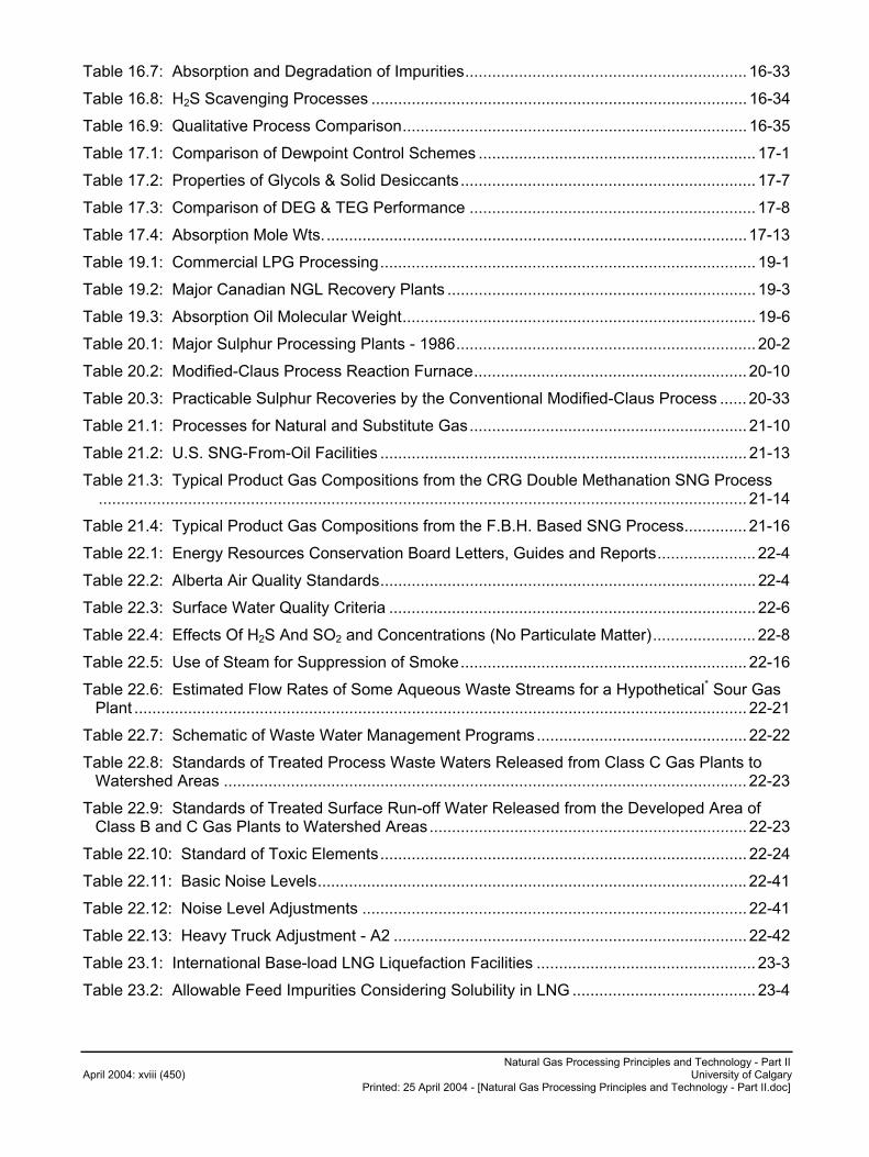
Natural Gas Processing Principles and Technology - Part II April 2004: xviii (450) University of Calgary
Printed: 25 April 2004 - [Natural Gas Processing Principles and Technology - Part II.doc]
Table 16.7: Absorption and Degradation of Impurities............................................................... 16-33
Table 16.8: H2S Scavenging Processes .................................................................................... 16-34
Table 16.9: Qualitative Process Comparison............................................................................. 16-35
Table 17.1: Comparison of Dewpoint Control Schemes .............................................................. 17-1
Table 17.2: Properties of Glycols & Solid Desiccants.................................................................. 17-7
Table 17.3: Comparison of DEG & TEG Performance ................................................................ 17-8
Table 17.4: Absorption Mole Wts...............................................................................................17-13
Table 19.1: Commercial LPG Processing.................................................................................... 19-1
Table 19.2: Major Canadian NGL Recovery Plants ..................................................................... 19-3
Table 19.3: Absorption Oil Molecular Weight............................................................................... 19-6
Table 20.1: Major Sulphur Processing Plants - 1986................................................................... 20-2
Table 20.2: Modified-Claus Process Reaction Furnace............................................................. 20-10
Table 20.3: Practicable Sulphur Recoveries by the Conventional Modified-Claus Process ...... 20-33
Table 21.1: Processes for Natural and Substitute Gas.............................................................. 21-10
Table 21.2: U.S. SNG-From-Oil Facilities .................................................................................. 21-13
Table 21.3: Typical Product Gas Compositions from the CRG Double Methanation SNG Process................................................................................................................................................. 21-14
Table 21.4: Typical Product Gas Compositions from the F.B.H. Based SNG Process.............. 21-16
Table 22.1: Energy Resources Conservation Board Letters, Guides and Reports...................... 22-4
Table 22.2: Alberta Air Quality Standards.................................................................................... 22-4
Table 22.3: Surface Water Quality Criteria .................................................................................. 22-6
Table 22.4: Effects Of H2S And SO2 and Concentrations (No Particulate Matter)....................... 22-8
Table 22.5: Use of Steam for Suppression of Smoke................................................................ 22-16
Table 22.6: Estimated Flow Rates of Some Aqueous Waste Streams for a Hypothetical* Sour Gas Plant ......................................................................................................................................... 22-21
Table 22.7: Schematic of Waste Water Management Programs............................................... 22-22
Table 22.8: Standards of Treated Process Waste Waters Released from Class C Gas Plants to Watershed Areas ..................................................................................................................... 22-23
Table 22.9: Standards of Treated Surface Run-off Water Released from the Developed Area of Class B and C Gas Plants to Watershed Areas....................................................................... 22-23
Table 22.10: Standard of Toxic Elements.................................................................................. 22-24
Table 22.11: Basic Noise Levels................................................................................................ 22-41
Table 22.12: Noise Level Adjustments ...................................................................................... 22-41
Table 22.13: Heavy Truck Adjustment - A2 ............................................................................... 22-42
Table 23.1: International Base-load LNG Liquefaction Facilities ................................................. 23-3
Table 23.2: Allowable Feed Impurities Considering Solubility in LNG ......................................... 23-4
Natural Gas Processing Principles and Technology - Part II University of Calgary April 2004: xix (450) Printed: 25 April 2004 - [Natural Gas Processing Principles and Technology - Part II.doc]
Table 23.3: Import Receiving Terminals - Japan........................................................................23-27
Table 23.4: Import Receiving Terminals - Europe......................................................................23-29
Table 23.5: Import Receiving Terminals – U.S. and Canada .....................................................23-30
Table 23.6: Aboveground LNG Tank Alternatives......................................................................23-38
Table 24.1: Raw Gas Quality Description ....................................................................................24-1
Table 24.2: Small Gas Facilities (to 1.5 x 10⁶ m3/day - 53 MMSCFD) .........................................24-1
Table 24.3: Large Gas Facilities (greater then 1.5 x 10⁶ m3/day - 53 MMSCFD).........................24-2
Natural Gas Processing Principles and Technology - Part II April 2004: xx (450) University of Calgary
Printed: 25 April 2004 - [Natural Gas Processing Principles and Technology - Part II.doc]
Purpose of this Document 1. To study the physical, chemical and engineering principles used in the handling of
natural gas, substitute natural gas, their associated liquids, and the other compounds obtained from them.
2. To apply these principles to actual design and operating problems.
Preface The gas processing industry in the past 25 years has developed extensively. Many different qualities of gas have been discovered and are being processed. Many different processing schemes are used to accomplish the same ends. This book tries to outline the major ways that this is being done, and to make the reader aware of the main areas of technology that are considered in gas processing and handling.
This book is intended for practising engineers of all disciplines as a guide for them in the gas processing industry as gas engineers come from all branches of engineering.
At the end of most chapters, typical problems that might be encountered in industry are given. As these are practical problems, more than the principles of the particular chapter have to be used to solve the problems.
The Gas Processors Suppliers Association Engineering Data Book1 has been referred to extensively for data and other material as it is the basic reference book for the industry.
This book has been developed from the lecture notes developed by the author for a course given by him at the University of Calgary in the Department of Chemical Engineering over the past 24 years, and at other centres in both North America and Europe. During that period, several people have lectured in various sections of the course and have helped in the preparation of the text. These are, with the address when they participated in the course or their present address are as follows:
Dr. N. Anderson, Kilborn Engineering, Toronto, Ontario
Dr. K. Aziz, Stanford University, Palo Alto, California
Mr. E. Berlie, Western Research & Development, Calgary, Alberta
Dr. A. Chakma, University of Calgary, Calgary, Alberta
Dr. P.R. Bishnoi, University of Calgary, Calgary, Alberta
Dr. K. Goddard, Chevron Standard, Calgary, Alberta
Dr. G.A. Gregory, Neotechnology Consultants Ltd., Calgary, Alberta
Mr. G.E. Handwerk, Consultant, Denver, Colorado
Dr. R.A. Heidemann, University of Calgary, Calgary, Alberta
Mr. G. Kinsep, SKM Consulting, Calgary, Alberta
1 Published by the Gas Processors Suppliers Association and the Gas Processors Association, Tulsa, Oklahoma. Latest edition is the 10th edition
which is published in English Units only. Page No.'s in the text refer to the Metric edition or the 9th English edition unless otherwise noted.
Natural Gas Processing Principles and Technology - Part II University of Calgary April 2004: xxi (450) Printed: 25 April 2004 - [Natural Gas Processing Principles and Technology - Part II.doc]
Mr. M.A. Kyllo, Ralph M. Parsons Company Ltd., London, England
Dr. D. Leahey, Western Research, Calgary, Alberta
Mr. J. Lore, Lore & Associates, Calgary, Alberta
Mr. D. Mcoy, Canterra Energy, Calgary, Alberta
Mr. K.C. Milne, SKM Consulting, Calgary, Alberta
Dr. M.F. Mohtadi, University of Calgary, Calgary, Alberta
Dr. R.G. Moore, University of Calgary, Calgary, Alberta
Mr. H.G. Paskell, Western Research, Calgary, Alberta
Dr. D.B. Robinson, University of Alberta, Edmonton, Alberta
Mr. J. Same, Western Research, Calgary, Alberta
Dr. W.Y. Svrcek, University of Calgary, Calgary, Alberta
Dr. E.L. Tollefson, University of Calgary, Calgary, Alberta
Mr. E. Wichert, Petro Canada, Calgary, Alberta
Also, as the notes are based on the author's more than 30 years in the gas processing industry, he wishes to acknowledge the many persons not already acknowledged who contributed data and suggestions incorporate in the book.
The more recent revisions have been made to bring the notes up—to—date and to show both metric units and English units whenever appropriate. The problem of using metric units is that the source of much of the data is the 9th edition of GPSA Metric Data book, which is based on 1972 data. There is now available a 10th edition of this book which was published in 1987 that gives English units only. This is a much more complete reference book and as such will be used extensively in class.
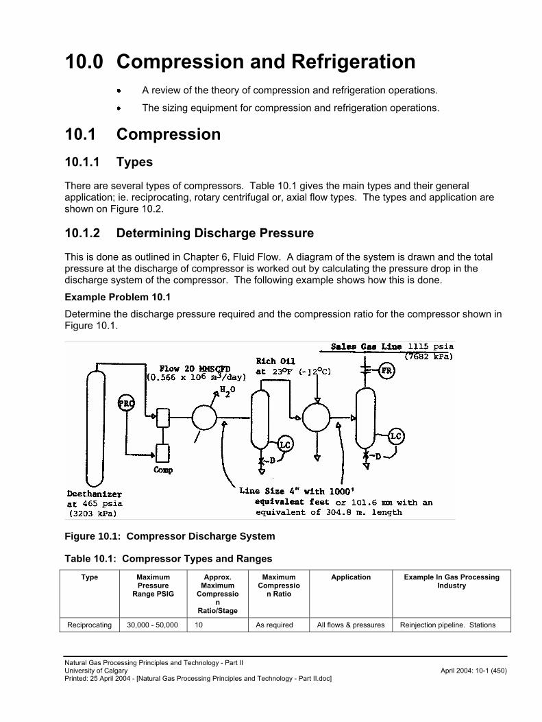
Natural Gas Processing Principles and Technology - Part II University of Calgary April 2004: 10-1 (450) Printed: 25 April 2004 - [Natural Gas Processing Principles and Technology - Part II.doc]
10.0 Compression and Refrigeration
� A review of the theory of compression and refrigeration operations.
� The sizing equipment for compression and refrigeration operations.
10.1 Compression
10.1.1 Types
There are several types of compressors. Table 10.1 gives the main types and their general application; ie. reciprocating, rotary centrifugal or, axial flow types. The types and application are shown on Figure 10.2.
10.1.2 Determining Discharge Pressure
This is done as outlined in Chapter 6, Fluid Flow. A diagram of the system is drawn and the total pressure at the discharge of compressor is worked out by calculating the pressure drop in the discharge system of the compressor. The following example shows how this is done.
Example Problem 10.1
Determine the discharge pressure required and the compression ratio for the compressor shown in Figure 10.1.
Figure 10.1: Compressor Discharge System
Table 10.1: Compressor Types and Ranges
Type Maximum Pressure
Range PSIG
Approx. Maximum
Compression
Ratio/Stage
Maximum Compressio
n Ratio
Application Example In Gas Processing Industry
Reciprocating 30,000 - 50,000 10 As required All flows & pressures Reinjection pipeline. Stations
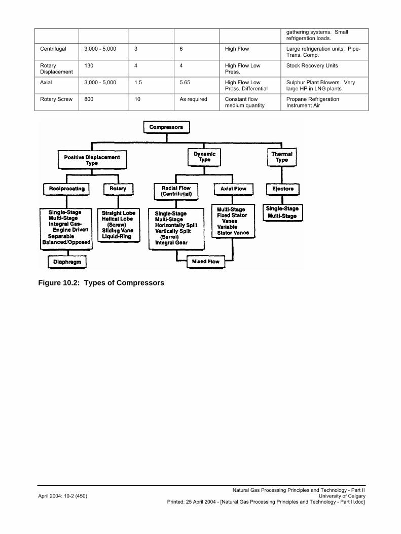
Natural Gas Processing Principles and Technology - Part II April 2004: 10-2 (450) University of Calgary
Printed: 25 April 2004 - [Natural Gas Processing Principles and Technology - Part II.doc]
gathering systems. Small refrigeration loads.
Centrifugal 3,000 - 5,000 3 6 High Flow Large refrigeration units. Pipe-Trans. Comp.
Rotary Displacement
130 4 4 High Flow Low Press.
Stock Recovery Units
Axial 3,000 - 5,000 1.5 5.65 High Flow Low Press. Differential
Sulphur Plant Blowers. Very large HP in LNG plants
Rotary Screw 800 10 As required Constant flow medium quantity
Propane Refrigeration Instrument Air
Figure 10.2: Types of Compressors
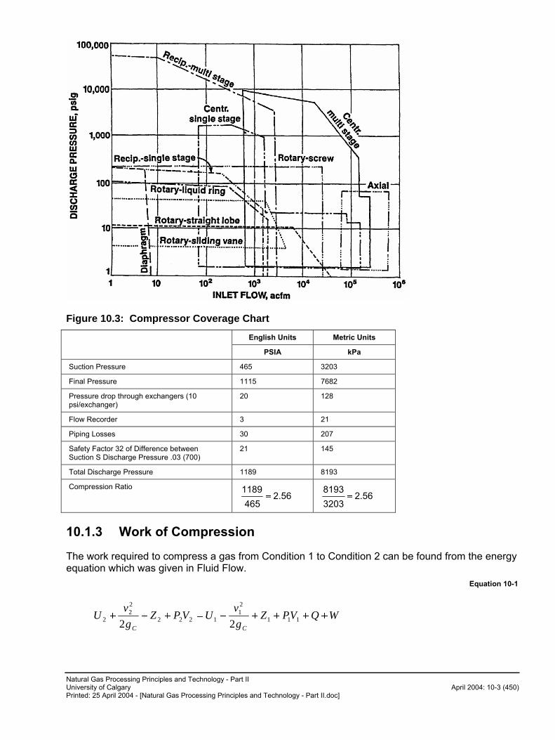
Natural Gas Processing Principles and Technology - Part II University of Calgary April 2004: 10-3 (450) Printed: 25 April 2004 - [Natural Gas Processing Principles and Technology - Part II.doc]
Figure 10.3: Compressor Coverage Chart
English Units Metric Units
PSIA kPa
Suction Pressure 465 3203
Final Pressure 1115 7682
Pressure drop through exchangers (10 psi/exchanger)
20 128
Flow Recorder 3 21
Piping Losses 30 207
Safety Factor 32 of Difference between Suction S Discharge Pressure .03 (700)
21 145
Total Discharge Pressure 1189 8193
Compression Ratio
2.56465
1189� 2.56
3203
8193�
10.1.3 Work of Compression
The work required to compress a gas from Condition 1 to Condition 2 can be found from the energy equation which was given in Fluid Flow.
Equation 10-1
WQVPZg
vUVPZ
g
vU
CC
��������� 111
21
1222
22
2 22
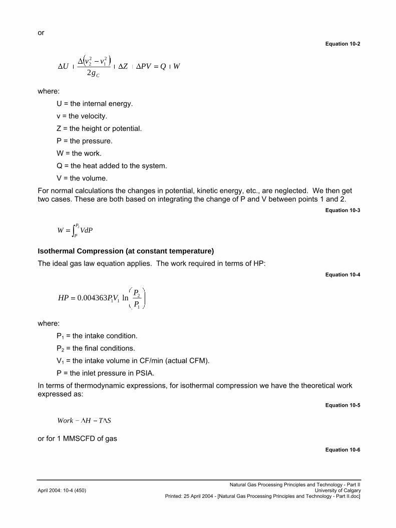
Natural Gas Processing Principles and Technology - Part II April 2004: 10-4 (450) University of Calgary
Printed: 25 April 2004 - [Natural Gas Processing Principles and Technology - Part II.doc]
or
Equation 10-2
� �WQPVZ
g
vvU
C
��������
��2
21
22
where:
U = the internal energy.
v = the velocity.
Z = the height or potential.
P = the pressure.
W = the work.
Q = the heat added to the system.
V = the volume.
For normal calculations the changes in potential, kinetic energy, etc., are neglected. We then get two cases. These are both based on integrating the change of P and V between points 1 and 2.
Equation 10-3
�2P
PVdPW
Isothermal Compression (at constant temperature)
The ideal gas law equation applies. The work required in terms of HP:
Equation 10-4
���
�
�
1
211 ln004363.0
P
PVPHP
where:
P1 = the intake condition.
P2 = the final conditions.
V1 = the intake volume in CF/min (actual CFM).
P = the inlet pressure in PSIA.
In terms of thermodynamic expressions, for isothermal compression we have the theoretical work expressed as:
Equation 10-5
STHWork ����
or for 1 MMSCFD of gas
Equation 10-6
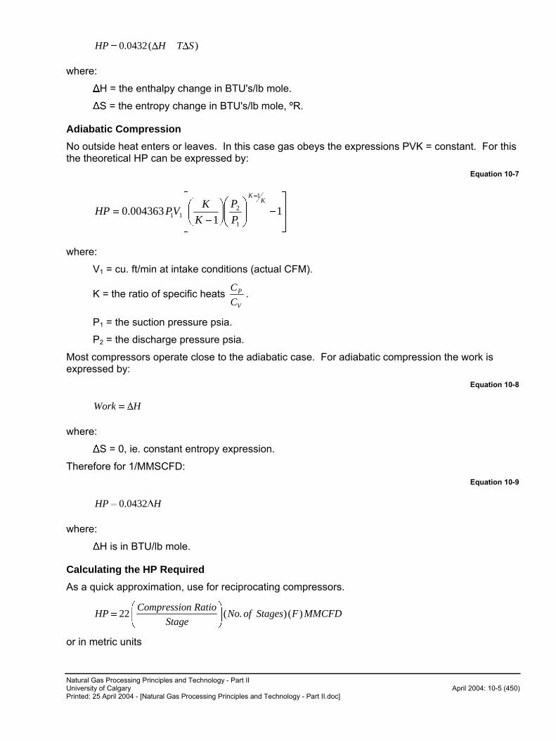
Natural Gas Processing Principles and Technology - Part II University of Calgary April 2004: 10-5 (450) Printed: 25 April 2004 - [Natural Gas Processing Principles and Technology - Part II.doc]
)(0432.0 STHHP ����
where:
�H = the enthalpy change in BTU's/lb mole.
�S = the entropy change in BTU's/lb mole, ºR.
Adiabatic Compression
No outside heat enters or leaves. In this case gas obeys the expressions PVK = constant. For this the theoretical HP can be expressed by:
Equation 10-7
��
�
�
��
�
��
�
���
���
��
�
�
�
11
004363.0
1
1
211
KK
P
P
K
KVPHP
where:
V1 = cu. ft/min at intake conditions (actual CFM).
K = the ratio of specific heats V
P
C
C.
P1 = the suction pressure psia.
P2 = the discharge pressure psia.
Most compressors operate close to the adiabatic case. For adiabatic compression the work is expressed by:
Equation 10-8
HWork ��
where:
�S = 0, ie. constant entropy expression.
Therefore for 1/MMSCFD:
Equation 10-9
HHP �� 0432.0
where:
�H is in BTU/lb mole.
Calculating the HP Required
As a quick approximation, use for reciprocating compressors.
MMCFDFStagesofNoStage
RationCompressioHP )().(22 ��
�
����
��
or in metric units
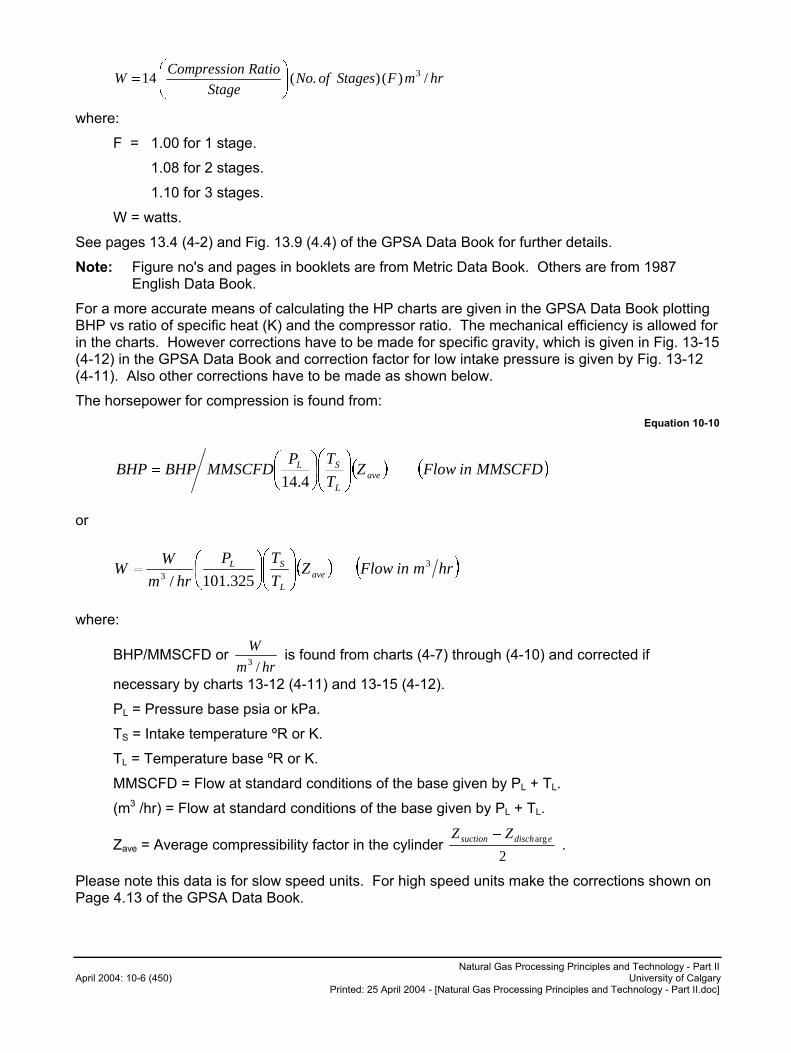
Natural Gas Processing Principles and Technology - Part II April 2004: 10-6 (450) University of Calgary
Printed: 25 April 2004 - [Natural Gas Processing Principles and Technology - Part II.doc]
hrmFStagesofNoStage
RationCompressioW /)().(14 3
���
����
��
where:
F = 1.00 for 1 stage.
1.08 for 2 stages.
1.10 for 3 stages.
W = watts.
See pages 13.4 (4-2) and Fig. 13.9 (4.4) of the GPSA Data Book for further details.
Note: Figure no's and pages in booklets are from Metric Data Book. Others are from 1987 English Data Book.
For a more accurate means of calculating the HP charts are given in the GPSA Data Book plotting BHP vs ratio of specific heat (K) and the compressor ratio. The mechanical efficiency is allowed for in the charts. However corrections have to be made for specific gravity, which is given in Fig. 13-15 (4-12) in the GPSA Data Book and correction factor for low intake pressure is given by Fig. 13-12 (4-11). Also other corrections have to be made as shown below.
The horsepower for compression is found from:
Equation 10-10
� � � �MMSCFDinFlowZT
TPMMSCFDBHPBHP ave
L
SL
���
�
��
��
4.14
or
� � � �hrminFlowZT
TP
hrm
WW ave
L
SL 33 325.101/
���
�
��
��
where:
BHP/MMSCFD or hrm
W
/3 is found from charts (4-7) through (4-10) and corrected if
necessary by charts 13-12 (4-11) and 13-15 (4-12).
PL = Pressure base psia or kPa.
TS = Intake temperature ºR or K.
TL = Temperature base ºR or K.
MMSCFD = Flow at standard conditions of the base given by PL + TL.
(m3 /hr) = Flow at standard conditions of the base given by PL + TL.
Zave = Average compressibility factor in the cylinder 2
argedischsuction ZZ � .
Please note this data is for slow speed units. For high speed units make the corrections shown on Page 4.13 of the GPSA Data Book.

Natural Gas Processing Principles and Technology - Part II University of Calgary April 2004: 10-7 (450) Printed: 25 April 2004 - [Natural Gas Processing Principles and Technology - Part II.doc]
10.1.4 Compression Ratio
essureAbsoluteSuction
essureAbsoluteeDisch
Pr
Prarg
Normally do not use a compression ratio of greater than 6 for single stage compression. Generally it is around 3.
10.1.5 Ratio of Specific Heats
In the equation for adiabatic compression the term K is used. It is the ratio of the specific heat at constant pressure (Cp) and specific heat at constant volume (CV). It can be calculated if the value of the specific heat at constant pressure is known from the equation
Equation 10-11
99.1�� VP MCMC
where:
M = molecular weight.
Therefore
Equation 10-12
99.1�
�
P
P
MC
MCK
in metric units
3145.8��
P
P
MC
MCK
The GPSA Data Book, Fig. 4-1, gives the value of MC for most compounds P expected in natural gas at various temperatures so that a K for a mixture can be easily calculated. Some common values of K are:
for Air 1.4
for Natural Gas 1.26
For a quick calculation of "K" for hydrocarbon gases, use Fig. 4-3 of the GPSA Data Book.
The value of K is one of the most important values in determining the compression power required. The following example problem illustrates the calculations required.
Example Problem 10.2
Calculate the HP required to compress 80 MMSCFD of gas of the composition given below from 400 psia at 100ºF to 1100 psia.
First we have to calculate the ratio of specific heat V
p
C
CK �"" .
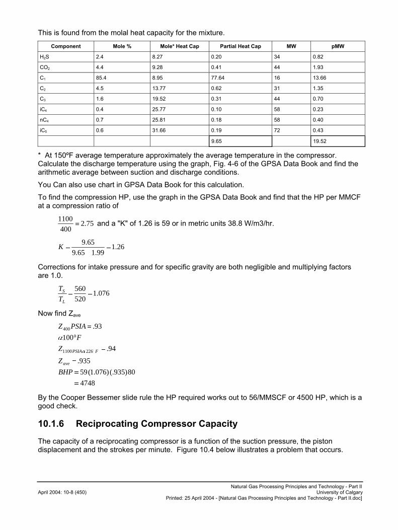
Natural Gas Processing Principles and Technology - Part II April 2004: 10-8 (450) University of Calgary
Printed: 25 April 2004 - [Natural Gas Processing Principles and Technology - Part II.doc]
This is found from the molal heat capacity for the mixture.
Component Mole % Mole* Heat Cap Partial Heat Cap MW pMW
H2S 2.4 8.27 0.20 34 0.82
CO2 4.4 9.28 0.41 44 1.93
C1 85.4 8.95 77.64 16 13.66
C2 4.5 13.77 0.62 31 1.35
C3 1.6 19.52 0.31 44 0.70
iC4 0.4 25.77 0.10 58 0.23
nC4 0.7 25.81 0.18 58 0.40
iC5 0.6 31.66 0.19 72 0.43
9.65 19.52
* At 150ºF average temperature approximately the average temperature in the compressor. Calculate the discharge temperature using the graph, Fig. 4-6 of the GPSA Data Book and find the arithmetic average between suction and discharge conditions.
You Can also use chart in GPSA Data Book for this calculation.
To find the compression HP, use the graph in the GPSA Data Book and find that the HP per MMCF at a compression ratio of
75.2400
1100� and a "K" of 1.26 is 59 or in metric units 38.8 W/m3/hr.
26.199.165.9
65.9�
��K
Corrections for intake pressure and for specific gravity are both negligible and multiplying factors are 1.0.
076.1520
560��
L
S
T
T
Now find Zave
4748
80)935(.)076.1(59
935.
94.
100
93.
2261100
400
�
�
�
�
�
�
�
BHP
Z
Z
F
PSIAZ
ave
FPSIA�
�
By the Cooper Bessemer slide rule the HP required works out to 56/MMSCF or 4500 HP, which is a good check.
10.1.6 Reciprocating Compressor Capacity
The capacity of a reciprocating compressor is a function of the suction pressure, the piston displacement and the strokes per minute. Figure 10.4 below illustrates a problem that occurs.
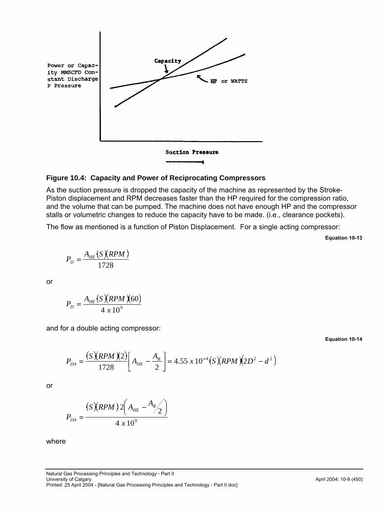
Natural Gas Processing Principles and Technology - Part II University of Calgary April 2004: 10-9 (450) Printed: 25 April 2004 - [Natural Gas Processing Principles and Technology - Part II.doc]
Figure 10.4: Capacity and Power of Reciprocating Compressors
As the suction pressure is dropped the capacity of the machine as represented by the Stroke-Piston displacement and RPM decreases faster than the HP required for the compression ratio, and the volume that can be pumped. The machine does not have enough HP and the compressor stalls or volumetric changes to reduce the capacity have to be made. (i.e., clearance pockets).
The flow as mentioned is a function of Piston Displacement. For a single acting compressor:
Equation 10-13
� �� �
1728
RPMSAP HE
D �
or
� �� �� �9104
60
x
RPMSAP HE
D �
and for a double acting compressor:
Equation 10-14
� �� �� �� �� �� �224 21055.4
21728
2dDRPMSx
AA
RPMSP R
HEDA ��
��
� �
or
� �� �
9104
22
x
AARPMSP
RHE
DA
���
��� �
�
where
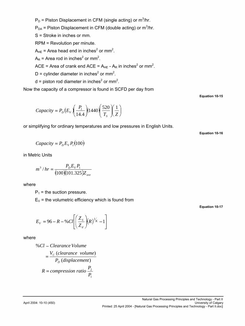
Natural Gas Processing Principles and Technology - Part II April 2004: 10-10 (450) University of Calgary
Printed: 25 April 2004 - [Natural Gas Processing Principles and Technology - Part II.doc]
PD = Piston Displacement in CFM (single acting) or m3/hr.
PDA = Piston Displacement in CFM (double acting) or m3/hr.
S = Stroke in inches or mm.
RPM = Revolution per minute.
AHE = Area head end in inches2 or mm2.
AR = Area rod in inches2 or mm2.
ACE = Area of crank end ACE = AHE - AR in inches2 or mm2.
D = cylinder diameter in inches2 or mm2.
d = piston rod diameter in inches2 or mm2.
Now the capacity of a compressor is found in SCFD per day from
Equation 10-15
� � � � ��
���
����
����
���
���
��
ZT
PEPCapacity
SVD
15201440
4.141
or simplifying for ordinary temperatures and low pressures in English Units.
Equation 10-16
1001PEPCapacity VD�
in Metric Units
� � ave
VD
Z
PEPhrm
325.101100/ 13 �
where
P1 = the suction pressure.
EV = the volumetric efficiency which is found from
Equation 10-17
� � ��
���
����
�
����
���� 1%96
1K
d
SV R
Z
ZClRE
where
1
2
)(
)(
%
P
PrationcompressioR
ntdisplacemeP
volumeclearanceV
VolumeClearanceCl
D
C
�
�
�
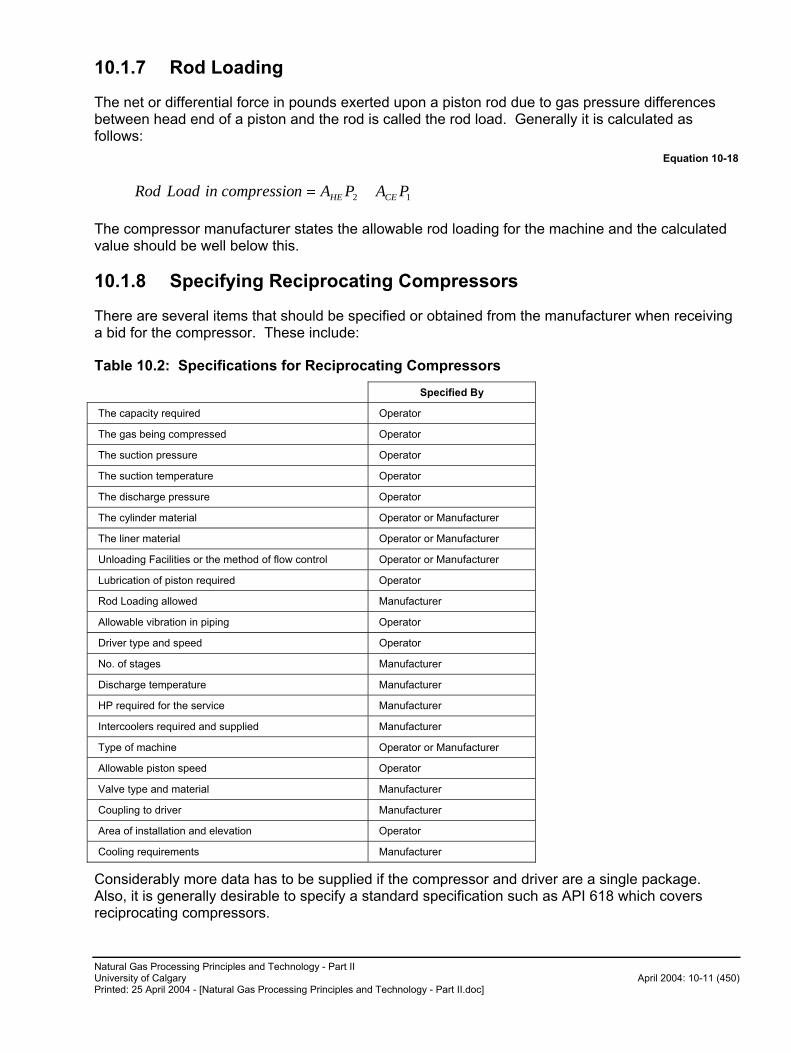
Natural Gas Processing Principles and Technology - Part II University of Calgary April 2004: 10-11 (450) Printed: 25 April 2004 - [Natural Gas Processing Principles and Technology - Part II.doc]
10.1.7 Rod Loading
The net or differential force in pounds exerted upon a piston rod due to gas pressure differences between head end of a piston and the rod is called the rod load. Generally it is calculated as follows:
Equation 10-18
12 PAPAncompressioinLoadRod CEHE ��
The compressor manufacturer states the allowable rod loading for the machine and the calculated value should be well below this.
10.1.8 Specifying Reciprocating Compressors
There are several items that should be specified or obtained from the manufacturer when receiving a bid for the compressor. These include:
Table 10.2: Specifications for Reciprocating Compressors
Specified By
The capacity required Operator
The gas being compressed Operator
The suction pressure Operator
The suction temperature Operator
The discharge pressure Operator
The cylinder material Operator or Manufacturer
The liner material Operator or Manufacturer
Unloading Facilities or the method of flow control Operator or Manufacturer
Lubrication of piston required Operator
Rod Loading allowed Manufacturer
Allowable vibration in piping Operator
Driver type and speed Operator
No. of stages Manufacturer
Discharge temperature Manufacturer
HP required for the service Manufacturer
Intercoolers required and supplied Manufacturer
Type of machine Operator or Manufacturer
Allowable piston speed Operator
Valve type and material Manufacturer
Coupling to driver Manufacturer
Area of installation and elevation Operator
Cooling requirements Manufacturer
Considerably more data has to be supplied if the compressor and driver are a single package. Also, it is generally desirable to specify a standard specification such as API 618 which covers reciprocating compressors.
Natural Gas Processing Principles and Technology - Part II April 2004: 10-12 (450) University of Calgary
Printed: 25 April 2004 - [Natural Gas Processing Principles and Technology - Part II.doc]
10.1.9 Trouble Shooting Reciprocating Compressors
There are many operating problems that can occur with reciprocating compressors. Table 10.3 from the latest GPSA Data Book (English units version) outlines many of the problems and their causes.
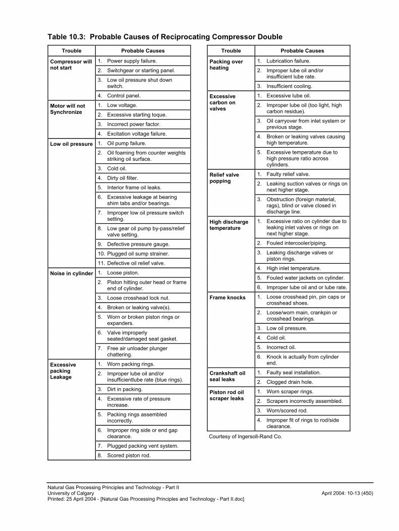
Natural Gas Processing Principles and Technology - Part II University of Calgary April 2004: 10-13 (450) Printed: 25 April 2004 - [Natural Gas Processing Principles and Technology - Part II.doc]
Table 10.3: Probable Causes of Reciprocating Compressor Double
Trouble Probable Causes
1. Power supply failure.
2. Switchgear or starting panel.
3. Low oil pressure shut down switch.
Compressor will not start
4. Control panel.
1. Low voltage.
2. Excessive starting toque.
3. Incorrect power factor.
Motor will not Synchronize
4. Excitation voltage failure.
1. Oil pump failure.
2. Oil foaming from counter weights striking oil surface.
3. Cold oil.
4. Dirty oil filter.
5. Interior frame oil leaks.
6. Excessive leakage at bearing shim tabs and/or bearings.
7. Improper low oil pressure switch setting.
8. Low gear oil pump by-pass/relief valve setting.
9. Defective pressure gauge.
10. Plugged oil sump strainer.
Low oil pressure
11. Defective oil relief valve.
1. Loose piston.
2. Piston hitting outer head or frame end of cylinder.
3. Loose crosshead lock nut.
4. Broken or leaking valve(s).
5. Worn or broken piston rings or expanders.
6. Valve improperly seated/damaged seat gasket.
Noise in cylinder
7. Free air unloader plunger chattering.
1. Worn packing rings.
2. Improper lube oil and/or insufficientlube rate (blue rings).
3. Dirt in packing.
4. Excessive rate of pressure increase.
5. Packing rings assembled incorrectly.
6. Improper ring side or end gap clearance.
7. Plugged packing vent system.
Excessive packing Leakage
8. Scored piston rod.
Trouble Probable Causes
1. Lubrication failure.
2. Improper lube oil and/or insufficient lube rate.
Packing over heating
3. Insufficient cooling.
1. Excessive lube oil.
2. Improper lube oil (too light, high carbon residue).
3. Oil carryover from inlet system or previous stage.
4. Broken or leaking valves causing high temperature.
Excessive carbon on valves
5. Excessive temperature due to high pressure ratio across cylinders.
1. Faulty relief valve.
2. Leaking suction valves or rings on next higher stage.
Relief valve popping
3. Obstruction (foreign material, rags), blind or valve closed in discharge line.
1. Excessive ratio on cylinder due to leaking inlet valves or rings on next higher stage.
2. Fouled intercooler/piping.
3. Leaking discharge valves or piston rings.
4. High inlet temperature.
5. Fouled water jackets on cylinder.
High discharge temperature
6. Improper lube oil and or lube rate.
1. Loose crosshead pin, pin caps or crosshead shoes.
2. Loose/worn main, crankpin or crosshead bearings.
3. Low oil pressure.
4. Cold oil.
5. Incorrect oil.
Frame knocks
6. Knock is actually from cylinder end.
1. Faulty seal installation. Crankshaft oil seal leaks
2. Clogged drain hole.
1. Worn scraper rings.
2. Scrapers incorrectly assembled.
3. Worn/scored rod.
Piston rod oil scraper leaks
4. lmproper fit of rings to rod/side clearance.
Courtesy of lngersoll-Rand Co.
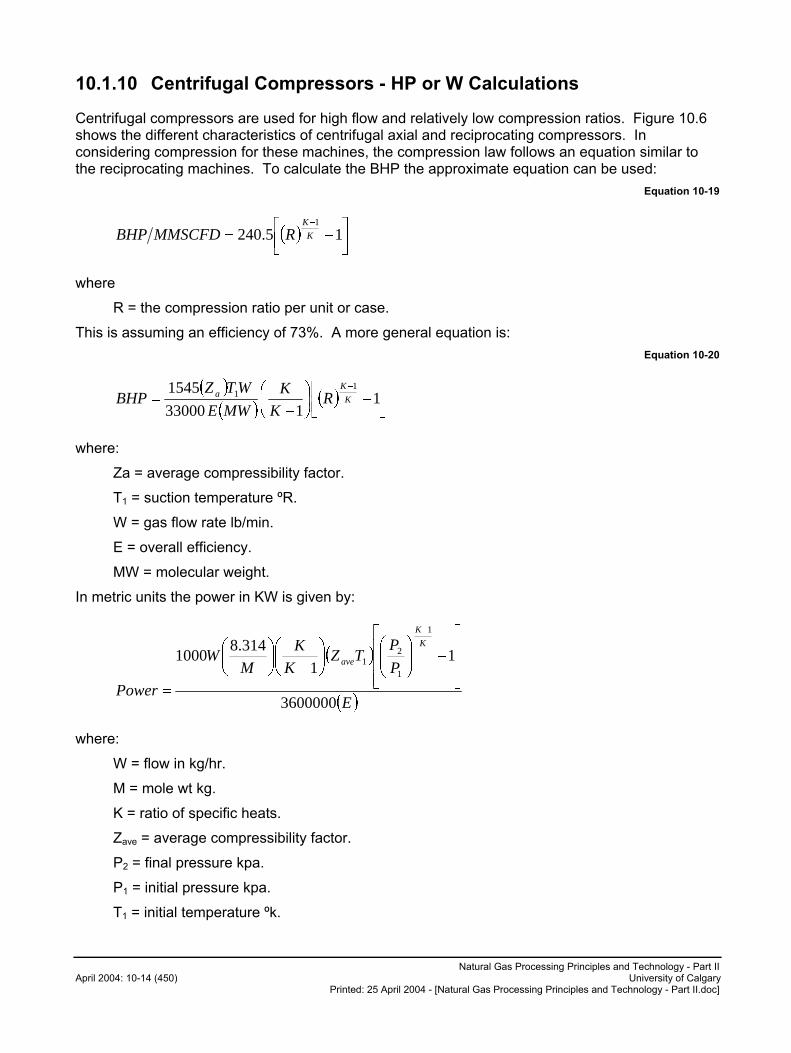
Natural Gas Processing Principles and Technology - Part II April 2004: 10-14 (450) University of Calgary
Printed: 25 April 2004 - [Natural Gas Processing Principles and Technology - Part II.doc]
10.1.10 Centrifugal Compressors - HP or W Calculations
Centrifugal compressors are used for high flow and relatively low compression ratios. Figure 10.6 shows the different characteristics of centrifugal axial and reciprocating compressors. In considering compression for these machines, the compression law follows an equation similar to the reciprocating machines. To calculate the BHP the approximate equation can be used:
Equation 10-19
� � ��
���
��
15.240
1
K
K
RMMSCFDBHP
where
R = the compression ratio per unit or case.
This is assuming an efficiency of 73%. A more general equation is:
Equation 10-20
� �
� �� � �
���
���
�
���
�
��
�1
133000
1545 11
K
Ka R
K
K
MWE
WTZBHP
where:
Za = average compressibility factor.
T1 = suction temperature ºR.
W = gas flow rate lb/min.
E = overall efficiency.
MW = molecular weight.
In metric units the power in KW is given by:
� �
� �E
P
PTZ
K
K
MW
Power
K
K
ave
3600000
11
314.81000
1
1
21
���
�
!!!
"
#
$%%&
'(()
*%&
'()
*
$%&
'()
*
+
,
where:
W = flow in kg/hr.
M = mole wt kg.
K = ratio of specific heats.
Zave = average compressibility factor.
P2 = final pressure kpa.
P1 = initial pressure kpa.
T1 = initial temperature ºk.

Natural Gas Processing Principles and Technology - Part II University of Calgary April 2004: 10-15 (450) Printed: 25 April 2004 - [Natural Gas Processing Principles and Technology - Part II.doc]
E = efficiency.
10.1.11 Centrifugal Compressors - General Operating Characteristics
The centrifugal (and the axial compressor) are generally like a centrifugal pump. They develop pressure from rotating blades or impellers and they have a performance curve as shown in the figure below.
Figure 10.5: Head Capacity Curve for Centrifugal Compressors
The system and the compressor characteristics have to meet. However the system can change by changing pressures and of course the compressor curve can be changed in many ways such as changing the speed, etc. The head required by the system is calculated from the following equation:
Equation 10-21
���
�
�
���
�
�
����
�
���
�
�
�
�
11
1
1
2K
K
adiabatic P
P
K
KZRTH
The compressor head developed is found from the equation
Equation 10-22
g
uH adiabatic
2
��
where
� = head coefficient and is a function of blade angle, efficiency, etc. It is normally 0.5 for industrial compressors and goes to 0.63 with radial blading.
u = tip speed ft/sec.
g = gravity.
Each stage of a compressor normally runs between 8000 to 12,000 feet of adiabatic head.
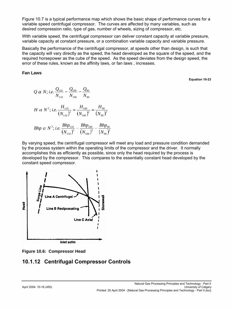
Natural Gas Processing Principles and Technology - Part II April 2004: 10-16 (450) University of Calgary
Printed: 25 April 2004 - [Natural Gas Processing Principles and Technology - Part II.doc]
Figure 10.7 is a typical performance map which shows the basic shape of performance curves for a variable speed centrifugal compressor. The curves are affected by many variables, such as desired compression ratio, type of gas, number of wheels, sizing of compressor, etc.
With variable speed, the centrifugal compressor can deliver constant capacity at variable pressure, variable capacity at constant pressure, or a combination variable capacity and variable pressure.
Basically the performance of the centrifugal compressor, at speeds other than design, is such that the capacity will vary directly as the speed, the head developed as the square of the speed, and the required horsepower as the cube of the speed. As the speed deviates from the design speed, the error of these rules, known as the affinity laws, or fan laws , increases.
Fan Laws Equation 10-23
90
90
100
100
110
110..;N
Q
N
Q
N
QeiNQ ���
� � � � � �2
90
902
100
1002
110
1102 ..;N
H
N
H
N
HeiNH ���
� � � � � �3
90
903
100
1003
110
1103 ..;N
Bhp
N
Bhp
N
BhpeiNBhp ���
By varying speed, the centrifugal compressor will meet any load and pressure condition demanded by the process system within the operating limits of the compressor and the driver. It normally accomplishes this as efficiently as possible, since only the head required by the process is developed by the compressor. This compares to the essentially constant head developed by the constant speed compressor.
Figure 10.6: Compressor Head
10.1.12 Centrifugal Compressor Controls
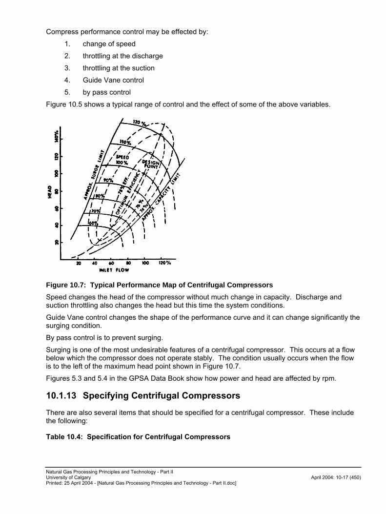
Natural Gas Processing Principles and Technology - Part II University of Calgary April 2004: 10-17 (450) Printed: 25 April 2004 - [Natural Gas Processing Principles and Technology - Part II.doc]
Compress performance control may be effected by:
1. change of speed
2. throttling at the discharge
3. throttling at the suction
4. Guide Vane control
5. by pass control
Figure 10.5 shows a typical range of control and the effect of some of the above variables.
Figure 10.7: Typical Performance Map of Centrifugal Compressors
Speed changes the head of the compressor without much change in capacity. Discharge and suction throttling also changes the head but this time the system conditions.
Guide Vane control changes the shape of the performance curve and it can change significantly the surging condition.
By pass control is to prevent surging.
Surging is one of the most undesirable features of a centrifugal compressor. This occurs at a flow below which the compressor does not operate stably. The condition usually occurs when the flow is to the left of the maximum head point shown in Figure 10.7.
Figures 5.3 and 5.4 in the GPSA Data Book show how power and head are affected by rpm.
10.1.13 Specifying Centrifugal Compressors
There are also several items that should be specified for a centrifugal compressor. These include the following:
Table 10.4: Specification for Centrifugal Compressors
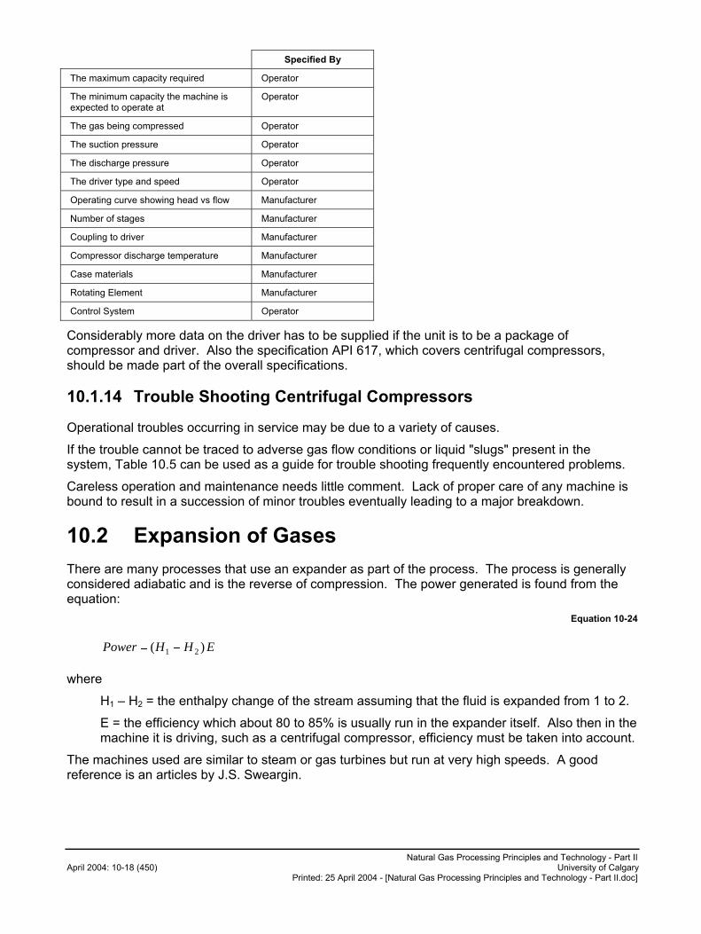
Natural Gas Processing Principles and Technology - Part II April 2004: 10-18 (450) University of Calgary
Printed: 25 April 2004 - [Natural Gas Processing Principles and Technology - Part II.doc]
Specified By
The maximum capacity required Operator
The minimum capacity the machine is expected to operate at
Operator
The gas being compressed Operator
The suction pressure Operator
The discharge pressure Operator
The driver type and speed Operator
Operating curve showing head vs flow Manufacturer
Number of stages Manufacturer
Coupling to driver Manufacturer
Compressor discharge temperature Manufacturer
Case materials Manufacturer
Rotating Element Manufacturer
Control System Operator
Considerably more data on the driver has to be supplied if the unit is to be a package of compressor and driver. Also the specification API 617, which covers centrifugal compressors, should be made part of the overall specifications.
10.1.14 Trouble Shooting Centrifugal Compressors
Operational troubles occurring in service may be due to a variety of causes.
If the trouble cannot be traced to adverse gas flow conditions or liquid "slugs" present in the system, Table 10.5 can be used as a guide for trouble shooting frequently encountered problems.
Careless operation and maintenance needs little comment. Lack of proper care of any machine is bound to result in a succession of minor troubles eventually leading to a major breakdown.
10.2 Expansion of Gases
There are many processes that use an expander as part of the process. The process is generally considered adiabatic and is the reverse of compression. The power generated is found from the equation:
Equation 10-24
EHHPower )( 21 ��
where
H1 – H2 = the enthalpy change of the stream assuming that the fluid is expanded from 1 to 2.
E = the efficiency which about 80 to 85% is usually run in the expander itself. Also then in the machine it is driving, such as a centrifugal compressor, efficiency must be taken into account.
The machines used are similar to steam or gas turbines but run at very high speeds. A good reference is an articles by J.S. Sweargin.
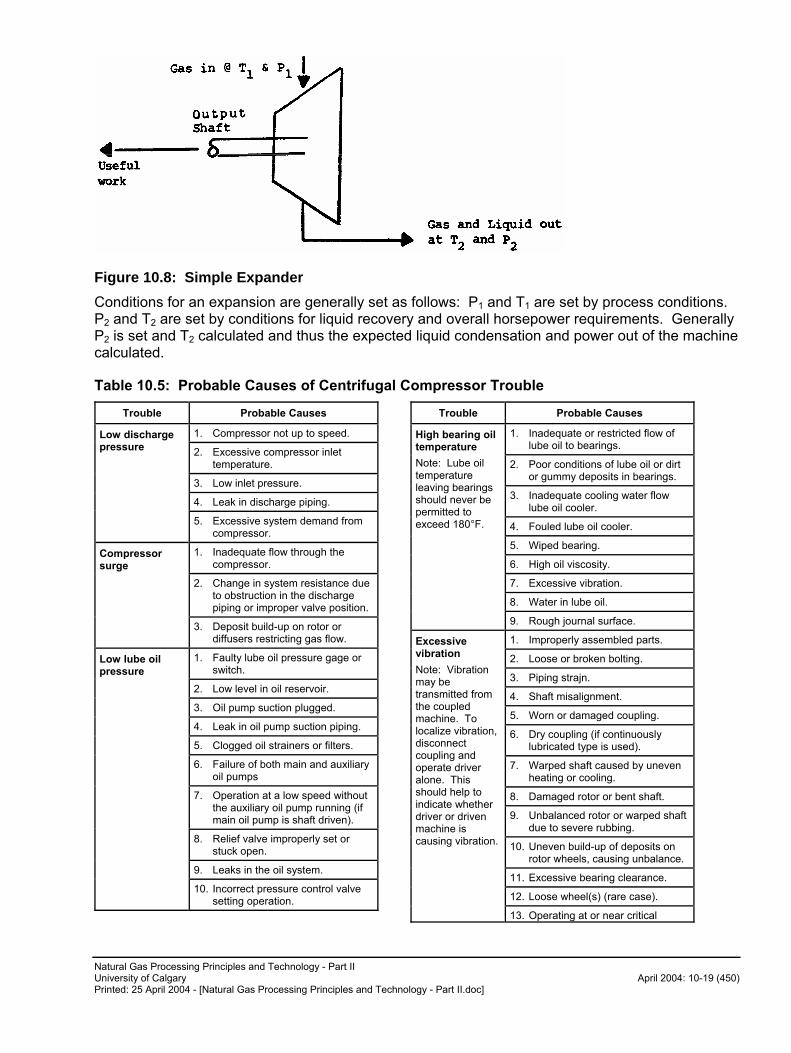
Natural Gas Processing Principles and Technology - Part II University of Calgary April 2004: 10-19 (450) Printed: 25 April 2004 - [Natural Gas Processing Principles and Technology - Part II.doc]
Figure 10.8: Simple Expander
Conditions for an expansion are generally set as follows: P1 and T1 are set by process conditions. P2 and T2 are set by conditions for liquid recovery and overall horsepower requirements. Generally P2 is set and T2 calculated and thus the expected liquid condensation and power out of the machine calculated.
Table 10.5: Probable Causes of Centrifugal Compressor Trouble
Trouble Probable Causes
1. Compressor not up to speed.
2. Excessive compressor inlet temperature.
3. Low inlet pressure.
4. Leak in discharge piping.
Low discharge pressure
5. Excessive system demand from compressor.
1. Inadequate flow through the compressor.
2. Change in system resistance due to obstruction in the discharge piping or improper valve position.
Compressor surge
3. Deposit build-up on rotor or diffusers restricting gas flow.
1. Faulty lube oil pressure gage or switch.
2. Low level in oil reservoir.
3. Oil pump suction plugged.
4. Leak in oil pump suction piping.
5. Clogged oil strainers or filters.
6. Failure of both main and auxiliary oil pumps
7. Operation at a low speed without the auxiliary oil pump running (if main oil pump is shaft driven).
8. Relief valve improperly set or stuck open.
9. Leaks in the oil system.
Low lube oil pressure
10. Incorrect pressure control valve setting operation.
Trouble Probable Causes
1. Inadequate or restricted flow of lube oil to bearings.
2. Poor conditions of lube oil or dirt or gummy deposits in bearings.
3. Inadequate cooling water flow lube oil cooler.
4. Fouled lube oil cooler.
5. Wiped bearing.
6. High oil viscosity.
7. Excessive vibration.
8. Water in lube oil.
High bearing oil temperature
Note: Lube oil temperature leaving bearings should never be permitted to exceed 180°F.
9. Rough journal surface.
1. Improperly assembled parts.
2. Loose or broken bolting.
3. Piping strajn.
4. Shaft misalignment.
5. Worn or damaged coupling.
6. Dry coupling (if continuously lubricated type is used).
7. Warped shaft caused by uneven heating or cooling.
8. Damaged rotor or bent shaft.
9. Unbalanced rotor or warped shaft due to severe rubbing.
10. Uneven build-up of deposits on rotor wheels, causing unbalance.
11. Excessive bearing clearance.
12. Loose wheel(s) (rare case).
Excessive vibration
Note: Vibration may be transmitted from the coupled machine. To localize vibration, disconnect coupling and operate driver alone. This should help to indicate whether driver or driven machine is causing vibration.
13. Operating at or near critical
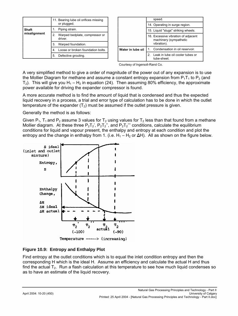
Natural Gas Processing Principles and Technology - Part II April 2004: 10-20 (450) University of Calgary
Printed: 25 April 2004 - [Natural Gas Processing Principles and Technology - Part II.doc]
11. Bearing lube oil orifices missing or plugged.
1. Piping strain.
2. Warped bedplate, compressor or driver.
3. Warped foundation.
4. Loose or broken foundation bolts.
Shaft misalignment
5. Defective grouting.
speed.
14. Operating in surge region.
15. Liquid "slugs" striking wheels.
16. Excessive vibration of adjacent machinery (sympathetic vibration).
1. Condensation in oil reservoir. Water in lube oil
2. Leak in lube oil cooler tubes or tube-sheet.
Courtesy of lngersoll-Rand Co.
A very simplified method to give a order of magnitude of the power out of any expansion is to use the Mollier Diagram for methane and assume a constant entropy expansion from P1T1 to P2 (and T2). This will give you H1 – H2 in equation (24). Then assuming 80% efficiency, the approximate power available for driving the expander compressor is found.
A more accurate method is to find the amount of liquid that is condensed and thus the expected liquid recovery in a process, a trial and error type of calculation has to be done in which the outlet temperature of the expander (T2) must be assumed if the outlet pressure is given.
Generally the method is as follows:
Given P1, T1 and P2 assume 3 values for T2 using values for T2 less than that found from a methane Mollier diagram. At these three P2T2’, P2T2’’, and P2T2’’’ conditions, calculate the equilibrium conditions for liquid and vapour present, the enthalpy and entropy at each condition and plot the entropy and the change in enthalpy from 1. (i.e. H1 – H2 or �H). All as shown on the figure below.
Figure 10.9: Entropy and Enthalpy Plot
Find entropy at the outlet conditions which is to equal the inlet condition entropy and then the corresponding H which is the ideal H. Assume an efficiency and calculate the actual H and thus find the actual T2. Run a flash calculation at this temperature to see how much liquid condenses so as to have an estimate of the liquid recovery.
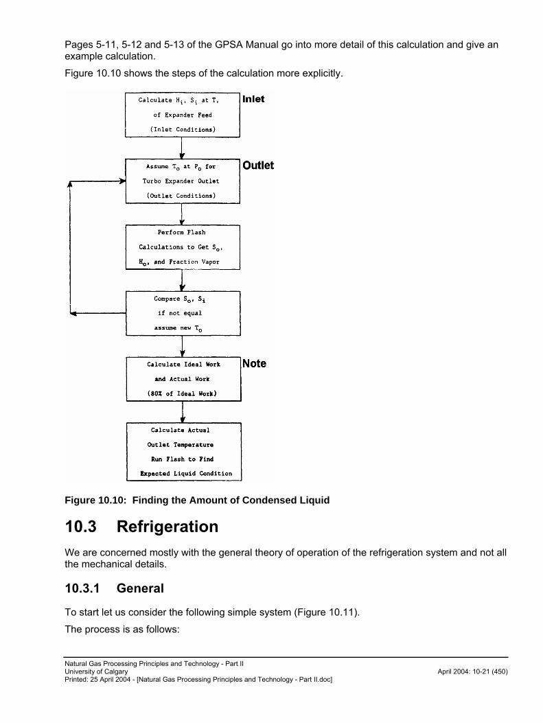
Natural Gas Processing Principles and Technology - Part II University of Calgary April 2004: 10-21 (450) Printed: 25 April 2004 - [Natural Gas Processing Principles and Technology - Part II.doc]
Pages 5-11, 5-12 and 5-13 of the GPSA Manual go into more detail of this calculation and give an example calculation.
Figure 10.10 shows the steps of the calculation more explicitly.
Figure 10.10: Finding the Amount of Condensed Liquid
10.3 Refrigeration
We are concerned mostly with the general theory of operation of the refrigeration system and not all the mechanical details.
10.3.1 General
To start let us consider the following simple system (Figure 10.11).
The process is as follows:

Natural Gas Processing Principles and Technology - Part II April 2004: 10-22 (450) University of Calgary
Printed: 25 April 2004 - [Natural Gas Processing Principles and Technology - Part II.doc]
Liquid refrigerant is vaporized in the evaporator to remove heat. It is recompressed by the compressor to high pressure, then condensed at the high pressure and collected in the surge drum. The liquid so formed is then throttled through the throttling valve into the chiller where all the liquid is evaporated and the cycle is repeated.
Figure 10.11: Typical Refrigeration System
The prime principle of a refrigeration machine is the absorbing of heat at a low temperature in the evaporator and rejecting this heat at a higher temperature in the condenser. It also depends on the Joule Thompson effect of constant enthalpy expansion.
Basically the cycle can be broken down into four steps as discussed above i.e. Expansion, Evaporation, Compression and Condensation and as shown on Fig. 10.12.
In Figure 10.11 let us define the heat conditions as follows:
Hb = heat content of refrigerant leaving chiller.
Hc = heat content of refrigerant leaving compressor.
He = heat content of refrigerant entering the chiller.
Also we define tons of refrigeration = amount of heat removed such that
1 ton = 200 BTU/min or 12,000 BTU/hr
In metric units we measure the KW of refrigeration and the brake power per KW of refrigeration.
The heat abstracted is
Hb - He
The work done is (assuming adiabatic compression) the change in enthalpy
Hc - Hb
The coefficient of performance � is defined as follows:
Equation 10-25
HbHc
HeHb
�
���
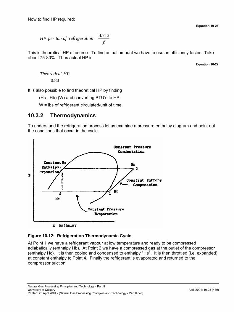
Natural Gas Processing Principles and Technology - Part II University of Calgary April 2004: 10-23 (450) Printed: 25 April 2004 - [Natural Gas Processing Principles and Technology - Part II.doc]
Now to find HP required:
Equation 10-26
�
713.4�ionrefrigeratoftonperHP
This is theoretical HP of course. To find actual amount we have to use an efficiency factor. Take about 75-80%. Thus actual HP is
Equation 10-27
80.0
HPlTheoretica
It is also possible to find theoretical HP by finding
(Hc - Hb) (W) and converting BTU’s to HP.
W = lbs of refrigerant circulated/unit of time.
10.3.2 Thermodynamics
To understand the refrigeration process let us examine a pressure enthalpy diagram and point out the conditions that occur in the cycle.
Figure 10.12: Refrigeration Thermodynamic Cycle
At Point 1 we have a refrigerant vapour at low temperature and ready to be compressed adiabatically (enthalpy Hb). At Point 2 we have a compressed gas at the outlet of the compressor (enthalpy Hc). It is then cooled and condensed to enthalpy "He". It is then throttled (i.e. expanded) at constant enthalpy to Point 4. Finally the refrigerant is evaporated and returned to the compressor suction.

Natural Gas Processing Principles and Technology - Part II April 2004: 10-24 (450) University of Calgary
Printed: 25 April 2004 - [Natural Gas Processing Principles and Technology - Part II.doc]
There are several modifications to the simple refrigeration system that can reduce the horsepower required in the system. The most common system is to use stages as described below.
10.3.2.1 Refrigeration Stages
Refrigeration systems utilizing one, two, three, or four stages of compression have been successfully operated in various services. The number of levels of refrigeration generally depends upon the number of compression stages required, interstage heat loads, economics, and the type of compression.
One-Stage Refrigeration System
A typical one-stage refrigeration system is shown in Fig. 10.13 where the data are for pure propane refrigerant.
Figure 10.13: One-Stage Refrigeration System
Two-Stage Refrigeration System
Savings in the 20% range can often be achieved with a two-stage refrigeration system and interstage flash economizer. Additional savings can be realized by removing process heat at the interstage level rather than at the low stage level. A typical two-stage system with an intermediate load is shown in Fig. 10.14 with data for pure propane.
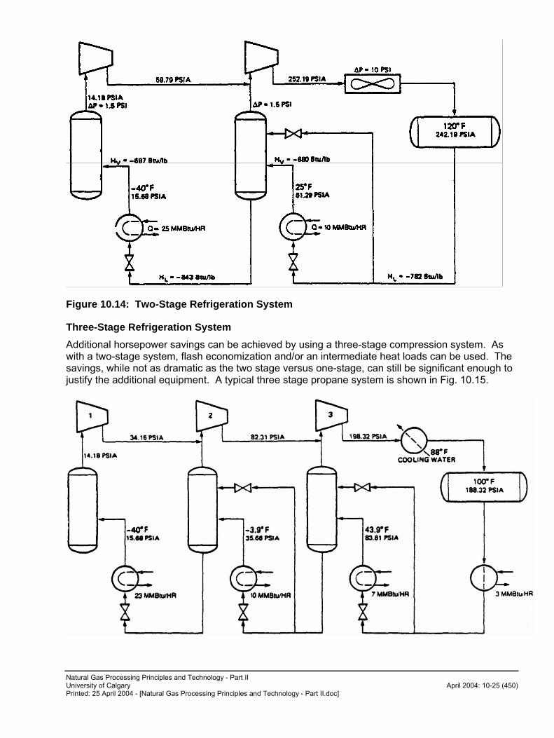
Natural Gas Processing Principles and Technology - Part II University of Calgary April 2004: 10-25 (450) Printed: 25 April 2004 - [Natural Gas Processing Principles and Technology - Part II.doc]
Figure 10.14: Two-Stage Refrigeration System
Three-Stage Refrigeration System
Additional horsepower savings can be achieved by using a three-stage compression system. As with a two-stage system, flash economization and/or an intermediate heat loads can be used. The savings, while not as dramatic as the two stage versus one-stage, can still be significant enough to justify the additional equipment. A typical three stage propane system is shown in Fig. 10.15.
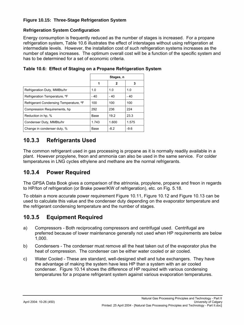
Natural Gas Processing Principles and Technology - Part II April 2004: 10-26 (450) University of Calgary
Printed: 25 April 2004 - [Natural Gas Processing Principles and Technology - Part II.doc]
Figure 10.15: Three-Stage Refrigeration System
Refrigeration System Configuration
Energy consumption is frequently reduced as the number of stages is increased. For a propane refrigeration system, Table 10.6 illustrates the effect of interstages without using refrigeration at intermediate levels. However, the installation cost of such refrigeration systems increases as the number of stages increases. The optimum overall cost will be a function of the specific system and has to be determined for a set of economic criteria.
Table 10.6: Effect of Staging on a Propane Refrigeration System
Stages, n
1 2 3
Refrigeration Duty, MMBtu/hr 1.0 1.0 1.0
Refrigeration Temperature, ºF - 40 - 40 - 40
Refrigerant Condensing Temperature, ºF 100 100 100
Compression Requirements, hp 292 236 224
Reduction in hp, % Base 19.2 23.3
Condenser Duty, MMBtu/hr 1.743 1.600 1.575
Change in condenser duty, % Base -8.2 -9.6
10.3.3 Refrigerants Used
The common refrigerant used in gas processing is propane as it is normally readily available in a plant. However propylene, freon and ammonia can also be used in the same service. For colder temperatures in LNG cycles ethylene and methane are the normal refrigerants.
10.3.4 Power Required
The GPSA Data Book gives a comparison of the atrinonia, propylene, propane and freon in regards to HP/ton of refrigeration (or Brake power/KW of refrigeration), etc. on Fig. 5.18.
To obtain a more accurate power requirement Figure 10.11, Figure 10.12 and Figure 10.13 can be used to calculate this value and the condenser duty depending on the evaporator temperature and the refrigerant condensing temperature and the number of stages.
10.3.5 Equipment Required
a) Compressors - Both reciprocating compressors and centrifugal used. Centrifugal are preferred because of lower maintenance generally not used when HP requirements are below 1,000.
b) Condensers - The condenser must remove all the heat taken out of the evaporator plus the heat of compression. The condenser can be either water cooled or air cooled.
c) Water Cooled - These are standard, well-designed shell and tube exchangers. They have the advantage of making the system have less HP than a system with an air cooled condenser. Figure 10.14 shows the difference of HP required with various condensing temperatures for a propane refrigerant system against various evaporation temperatures.
Natural Gas Processing Principles and Technology - Part II University of Calgary April 2004: 10-27 (450) Printed: 25 April 2004 - [Natural Gas Processing Principles and Technology - Part II.doc]
d) Air Cooled - These are standard air cooled condensers. The lowest condensing temperature that probably can be expected is about 20ºF above the design ambient temperature and thus the system requires more HP.
e) Economizer - This is an intermediate flash vessel that gets rid of some of the vapours that would be formed on direct throttling. Two stages are often used when more than two compression stages are used.
f) Throttling Valve - This is a standard control valve mostly operated on level control from the evaporator of chiller.
g) Evaporator (or Chiller) - A standard U-tube heat exchanger in which the refrigerant is normally on the outside of the tubes is used. A good disengaging space should be provided in the top of the refrigerant side to prevent liquid entrainment.
h) Suction Scrubber - This is a large vessel complete with entrainment separators, automatic liquid level dumps, etc. It is there to prevent any liquid carryover into the compressors.
i) Auxiliaries - Such units as refrigerant driers, oil removal facilities, purges, etc., are also generally provided.

Natural Gas Processing Principles and Technology - Part II April 2004: 10-28 (450) University of Calgary
Printed: 25 April 2004 - [Natural Gas Processing Principles and Technology - Part II.doc]
Figure 10.16: Single-Stage Propane Refrigeration System
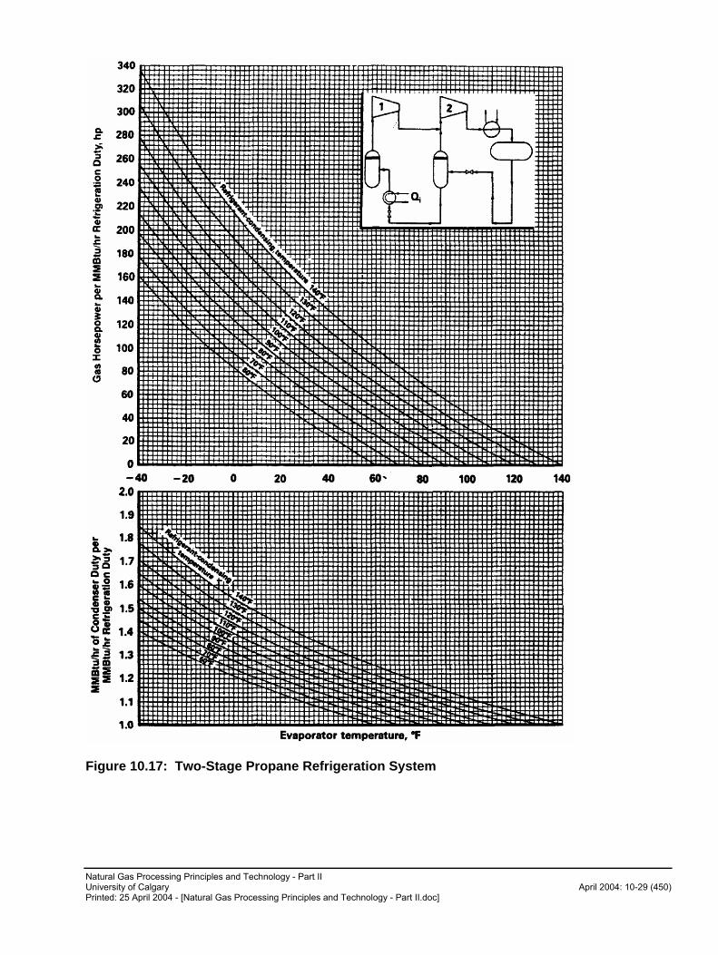
Natural Gas Processing Principles and Technology - Part II University of Calgary April 2004: 10-29 (450) Printed: 25 April 2004 - [Natural Gas Processing Principles and Technology - Part II.doc]
Figure 10.17: Two-Stage Propane Refrigeration System

Natural Gas Processing Principles and Technology - Part II April 2004: 10-30 (450) University of Calgary
Printed: 25 April 2004 - [Natural Gas Processing Principles and Technology - Part II.doc]
Figure 10.18: Three-Stage Propane Refrigeration System
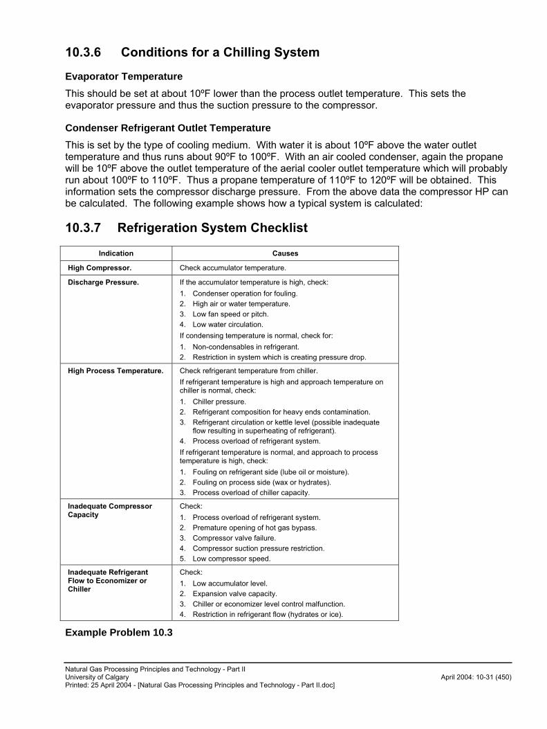
Natural Gas Processing Principles and Technology - Part II University of Calgary April 2004: 10-31 (450) Printed: 25 April 2004 - [Natural Gas Processing Principles and Technology - Part II.doc]
10.3.6 Conditions for a Chilling System
Evaporator Temperature
This should be set at about 10ºF lower than the process outlet temperature. This sets the evaporator pressure and thus the suction pressure to the compressor.
Condenser Refrigerant Outlet Temperature
This is set by the type of cooling medium. With water it is about 10ºF above the water outlet temperature and thus runs about 90ºF to 100ºF. With an air cooled condenser, again the propane will be 10ºF above the outlet temperature of the aerial cooler outlet temperature which will probably run about 100ºF to 110ºF. Thus a propane temperature of 110ºF to 120ºF will be obtained. This information sets the compressor discharge pressure. From the above data the compressor HP can be calculated. The following example shows how a typical system is calculated:
10.3.7 Refrigeration System Checklist
Indication Causes
High Compressor. Check accumulator temperature.
Discharge Pressure. If the accumulator temperature is high, check:
1. Condenser operation for fouling.
2. High air or water temperature.
3. Low fan speed or pitch.
4. Low water circulation.
If condensing temperature is normal, check for:
1. Non-condensables in refrigerant.
2. Restriction in system which is creating pressure drop.
High Process Temperature. Check refrigerant temperature from chiller.
If refrigerant temperature is high and approach temperature on chiller is normal, check:
1. Chiller pressure.
2. Refrigerant composition for heavy ends contamination.
3. Refrigerant circulation or kettle level (possible inadequate flow resulting in superheating of refrigerant).
4. Process overload of refrigerant system.
If refrigerant temperature is normal, and approach to process temperature is high, check:
1. Fouling on refrigerant side (lube oil or moisture).
2. Fouling on process side (wax or hydrates).
3. Process overload of chiller capacity.
Inadequate Compressor Capacity
Check:
1. Process overload of refrigerant system.
2. Premature opening of hot gas bypass.
3. Compressor valve failure.
4. Compressor suction pressure restriction.
5. Low compressor speed.
Inadequate Refrigerant Flow to Economizer or Chiller
Check:
1. Low accumulator level.
2. Expansion valve capacity.
3. Chiller or economizer level control malfunction.
4. Restriction in refrigerant flow (hydrates or ice).
Example Problem 10.3

Natural Gas Processing Principles and Technology - Part II April 2004: 10-32 (450) University of Calgary
Printed: 25 April 2004 - [Natural Gas Processing Principles and Technology - Part II.doc]
Calculate the HP required for refrigeration to chill 100 MMSCFD of a gas at 937 psig of the composition listed below from 40ºF to 0ºF using propane as a refrigerant. The evaporator temperature is -10ºF and the propane condenser operates to condense the propane to a liquid at 95ºF.
Composition Mole %
N2 0.00
C1 95.62
C2 3.01
C3 0.67
iC4 0.18
nC4 0.20
iC5 0.09
nC5 0.09
C6 0.14
Solution
First find the amount of heat to be removed in the chillers. This is found by enthalpy calculations.
This calculation is shown in Example Problem 2 in Chapter 2. The duty is equal to 5,727,028
BTU/HR or 41812000
028.727,5� tons of refrigeration.
In metric this equals 1679 KW.
Next calculate the refrigeration HP, finding the coefficient of performance:
bc
eb
HH
HH
�
�
For this condition, using Propane Mollier Diagram in GPSA Data Book:
Hb at -10ºF and saturated vapour = -690 BTU/lb
He at 95ºF and saturated liquid = -800 at (175 psia-condensing pressure)
Hc at 118ºF and 175 psia = -652
� = 90.2)690(652
)800(690�
���
���
HP per ton of refrigeration
62.190.2
713.4713.4��
�
This is a theoretical value. Divide by efficiency of 80% to get brake HP
tonHP /02.280.
62.1�
Compare this with value obtained from Fig. 5-14 of the GPSA Data Book.
2.03 HP/ton for conditions:
HP required using calculated HP/ton = 2.02 (481) = 971.6
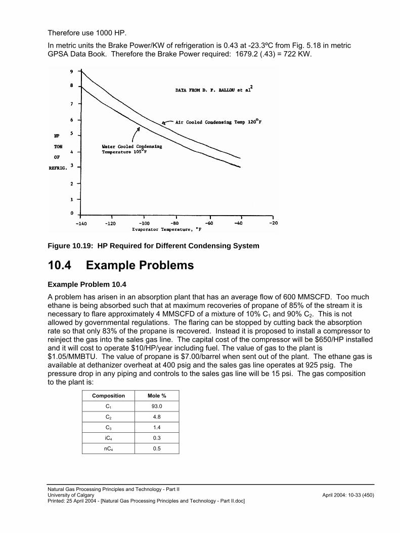
Natural Gas Processing Principles and Technology - Part II University of Calgary April 2004: 10-33 (450) Printed: 25 April 2004 - [Natural Gas Processing Principles and Technology - Part II.doc]
Therefore use 1000 HP.
In metric units the Brake Power/KW of refrigeration is 0.43 at -23.3ºC from Fig. 5.18 in metric GPSA Data Book. Therefore the Brake Power required: 1679.2 (.43) = 722 KW.
Figure 10.19: HP Required for Different Condensing System
10.4 Example Problems
Example Problem 10.4
A problem has arisen in an absorption plant that has an average flow of 600 MMSCFD. Too much ethane is being absorbed such that at maximum recoveries of propane of 85% of the stream it is necessary to flare approximately 4 MMSCFD of a mixture of 10% C1 and 90% C2. This is not allowed by governmental regulations. The flaring can be stopped by cutting back the absorption rate so that only 83% of the propane is recovered. Instead it is proposed to install a compressor to reinject the gas into the sales gas line. The capital cost of the compressor will be $650/HP installed and it will cost to operate $10/HP/year including fuel. The value of gas to the plant is $1.05/MMBTU. The value of propane is $7.00/barrel when sent out of the plant. The ethane gas is available at dethanizer overheat at 400 psig and the sales gas line operates at 925 psig. The pressure drop in any piping and controls to the sales gas line will be 15 psi. The gas composition to the plant is:
Composition Mole %
C1 93.0
C2 4.8
C3 1.4
iC4 0.3
nC4 0.5
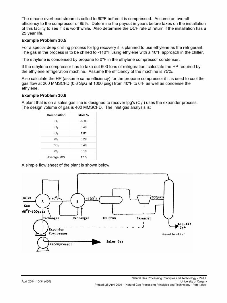
Natural Gas Processing Principles and Technology - Part II April 2004: 10-34 (450) University of Calgary
Printed: 25 April 2004 - [Natural Gas Processing Principles and Technology - Part II.doc]
The ethane overhead stream is colled to 60ºF before it is compressed. Assume an overall efficiency to the compressor of 85%. Determine the payout in years before taxes on the installation of this facility to see if it is worthwhile. Also determine the DCF rate of return if the installation has a 25 year life.
Example Problem 10.5
For a special deep chilling process for lpg recovery it is planned to use ethylene as the refrigerant. The gas in the process is to be chilled to -110ºF using ethylene with a 10ºF approach in the chiller.
The ethylene is condensed by propane to 0ºF in the ethylene compressor condenser.
If the ethylene compressor has to take out 600 tons of refrigeration, calculate the HP required by the ethylene refrigeration machine. Assume the efficiency of the machine is 75%.
Also calculate the HP (assume same efficiency) for the propane compressor if it is used to cool the gas flow at 200 MMSCFD (0.6 SpG at 1000 psig) from 40ºF to 0ºF as well as condense the ethylene.
Example Problem 10.6
A plant that is on a sales gas line is designed to recover lpg's (C3+) uses the expander process.
The design volume of gas is 400 MMSCFD. The inlet gas analysis is:
Composition Mole %
C1 92.00
C2 5.40
C3 1.81
iC4 0.29
nC4 0.40
iC5 0.10
Average MW 17.5
A simple flow sheet of the plant is shown below.
Natural Gas Processing Principles and Technology - Part II University of Calgary April 2004: 10-35 (450) Printed: 25 April 2004 - [Natural Gas Processing Principles and Technology - Part II.doc]
Exchanger B ruptures and is out of service for 4 months. You are to decide what is the best way to continue processing the gas from the following choices:
1. Bypass exchanger B on both sides and handle 400 MMSCFD in the expander. In this case the outlet process gas temperature from A is reduced to -40ºF because A has colder stripped gas entering it.
2. Bypass B and the expander and reduce the pressure to 300 psia by means of a throttle valve. The outlet of exchanger A is reduced to -80ºF in this case.
Assume that the reduction in flow is proportional to loss in HP from the expander being shut down, that is:
���
����
�
� CompressorfromsystemtoHPHPcompressor
ExpanderfromsystemtoHPMMSCFD
Re400
The recompressor HP is 24,000.
The expander system is 60% overall efficient.
Assume 5 psi drop per exchanger.
Assume pure methane for all expander enthalpy, entropy calculations.
Assume all C3+ that is liquefied is recovered.
Example Problem 10.7
One of the schemes for moving gas from the Arctic involves chilling the gas initially to remove the liquids and then keeping it cold so not to melt the permafrost.
Please calculate the approximate HP required at a compressor station that handles 5 MMSCFD of gas (measured at 14.4 psia and 60ºF) and the following takes place.
� Gas is compressed from 400 psia to 800 psia. The suction temperature is +25ºF.
� The gas is chilled from +80ºF to -5ºF so as to keep the gas cool enough to reach the next station at not greater than +25ºF.
Compare this with the case in which no chilling is put in the station and the gas is compressed at a suction temperature of +75ºF (summer conditions) from 400 psia to 800 psia.
Assumptions
a) Gas properties
MW = 18
cP/cV = 1.26
b) Enthalpy difference of cooling gas from 80ºF to -5ºF at 800 psia is 43 BTU's/lb.
c) Use propane as the chilling medium. Assume a 5ºF approach in the chiller and assume a 95ºF propane liquid condenser temperature.
d) Assume pipeline compressors are 85% efficient and that reciprocating compressors are used.
Natural Gas Processing Principles and Technology - Part II April 2004: 10-36 (450) University of Calgary
Printed: 25 April 2004 - [Natural Gas Processing Principles and Technology - Part II.doc]
References
3. J. S. Sweargin, Hydrocarbon Processing, April 1970, P. 97.
4. D. P. Ballou et al., Hydrocarbon Processing, June 1967, P. 119.
5. GPSA Data Book 1987 Edition Chapters 13 & iii.
Natural Gas Processing Principles and Technology - Part II University of Calgary April 2004: 11-1 (450) Printed: 25 April 2004 - [Natural Gas Processing Principles and Technology - Part II.doc]
11.0 Economics
� A review of the types of calculations used in justifying a project, ie. payouts, average annual rates of return.
� A look at the data required for these calculations.
11.1 Introduction
The determining of whether a project is commercially feasible is, of course, very important. There are several methods of determining whether a project or venture is economically desirable. These methods and their results are also used to decide which of many alternates are the most desirable.
11.2 Economics Indicators
a) Payout - This is the time from initial operation it takes for the project to generate enough cash to recover the investment made in the project. The cash flow is the sum of the net income after income tax plus the allowable income tax depreciation and, if allowed, the depletion allowance.
b) Discount Cash Flow Rate of Return - This is the interest rate which the actual investment is earning over the life of the project.
c) Number of Times Investment Return - This is the number of times that the earnings recover the investment. It is found by dividing the cash flow for the life of the project by the investment made.
d) Present Worth - This is the present day value of all future earnings. This is found by discounting the future earnings at a prescribed discount rate. Generally both a) and b) and often c) and d) should be worked out for each project. If alternates are being considered, all should be obtained.
e) Present Value Profit Ratio - This is the present value of all earnings at prescribed discount rate divided by the capital cost. Often companies set the minimum DCF rate of return acceptable and then calculate the present worth at this rate. The measure of a project is the present worth of a project above this minimum.
f) Others - There are several economic indicators such as the equivalent rate of return, simple rate of return, etc.
11.3 What is Considered a Good Investment
This, of course, depends a great deal on the size and type of project and on the risks involved in the project. The risks involved can be outlined as follows:
a) Markets Changing - Markets for products can disappear. This is unlikely with gas and by-products, which are primarily fuel. However, if they are not priced competitively, they can be reduced drastically as has happened to Canadian natural gas in the United States. For example, sulphur may be replaced if the price is too high. Also, there is the possibility of reduced market prices. This was not so significant with gas, but recently it has become a real possibility and is very much the case with LPG's and sulphur, but not condensates. For
Natural Gas Processing Principles and Technology - Part II April 2004: 11-2 (450) University of Calgary
Printed: 25 April 2004 - [Natural Gas Processing Principles and Technology - Part II.doc]
example, in 1967 sulphur was being sold at $50/LT f.o.b. plants and in 1971 was down as low as $4/LT. It has subsequently risen to over $150 in 1985.
b) Change of Costs - Plant costs can change, both capital and operating; these changes can generally be reasonably forecasted. However, with the shortages of labour and material, the cost of plants, pipelines, etc. go up, then with a recession they go down again as witnessed by 1983 and 1984 costs as compared to 1981 and 1982 costs. See the Nelson Index table later in this Section showing the changes with time. Inflation is generally a very big factor in capital costs. The risk in regard to plant capital costs are discussed later with the accuracy expected in cost estimating. (Also see reference #5 on this.)
c) New Technology - New plants become cheaper because of new technology. This change is not so important in gas processing as compared to petrochemical plants because the main product, gas, is often contracted for the life of the plant. Also, there has not been a major technical change in gas processing in the last ten years.
d) Government Regulations - This change is very difficult to forecast, as witnessed by the many changes in 1974, 1975 and 1981 in the petroleum industry via taxes, royalty rates, PIP grants, etc. This has become the most variable and unpredictable factor in economic evaluations.
All these factors have to be taken into account when evaluating projects. The higher the risk, the better the economic factors should be.
An article by D. Stahlberg discusses how to identify some of the risks. A formula that identifies the risk is as follows:
Equation 11-1
%100)(
% �
�
���
CostNetOriginalPlanSafeofCostNet
PlanSafeofCostNetOutWayofCostCostNetOriginalRisk
This % risk is compared with the chance of success, and if the success chance greatly outweighs the risks, then the riskier method should be tried.
Here are some guidelines for projects.
Minimum Payouts
For gas processing projects:
Before Taxes 3 - 4 years
After Taxes 6 - 7 years
For petrochemical projects where the risks are probably greater:
Before Taxes 2 - 3 years
After Taxes 5 years
Minimum Discounted Cash Flow After Taxes
For Gas Processing Plants 11% - 15%
For Petrochemicals 20%
For Pipelines 12%

Natural Gas Processing Principles and Technology - Part II University of Calgary April 2004: 11-3 (450) Printed: 25 April 2004 - [Natural Gas Processing Principles and Technology - Part II.doc]
11.4 Capital Costs
There are many types of capital cost estimates. The accuracy of these vary a great deal depending on the amount of information obtained and work done by the estimator. There is a great deal of information and data on the type and scope of estimates. A whole course could be given on making proper estimates. Also, there is a professional society devoted to cost engineering, the American Association of Cost Engineers. Figure 11.1 shows the approximate accuracy of estimates depending on the status of the project. Also Figure 11.2 gives a graphical outline of some of the types of estimates and the information needed for them. Each type of estimate requires a different amount of data to obtain.
11.4.1 Preliminary Feasibility Estimate
The preliminary feasibility estimate (order of magnitude).
As a very general guide the following can be used for gas plant costs:
Type of Gas Capital Cost - $/MMSCF
Very sour and rich 300,000 - 500,000
Medium sour 100,000 - 300,000
Sweet but rich 50,000 - 100,000
Dry and sweet 10,000 - 50,000
or you can use the method of E. Berlie.
11.4.2 Preliminary Budget Estimate
The concept or preliminary budget estimate can be done if you have the overall data on gas analysis, volumes, etc. This estimate is done by breaking the plant down into various process units and using general data for gathering pipelines, etc. The following table gives the curves that are included.
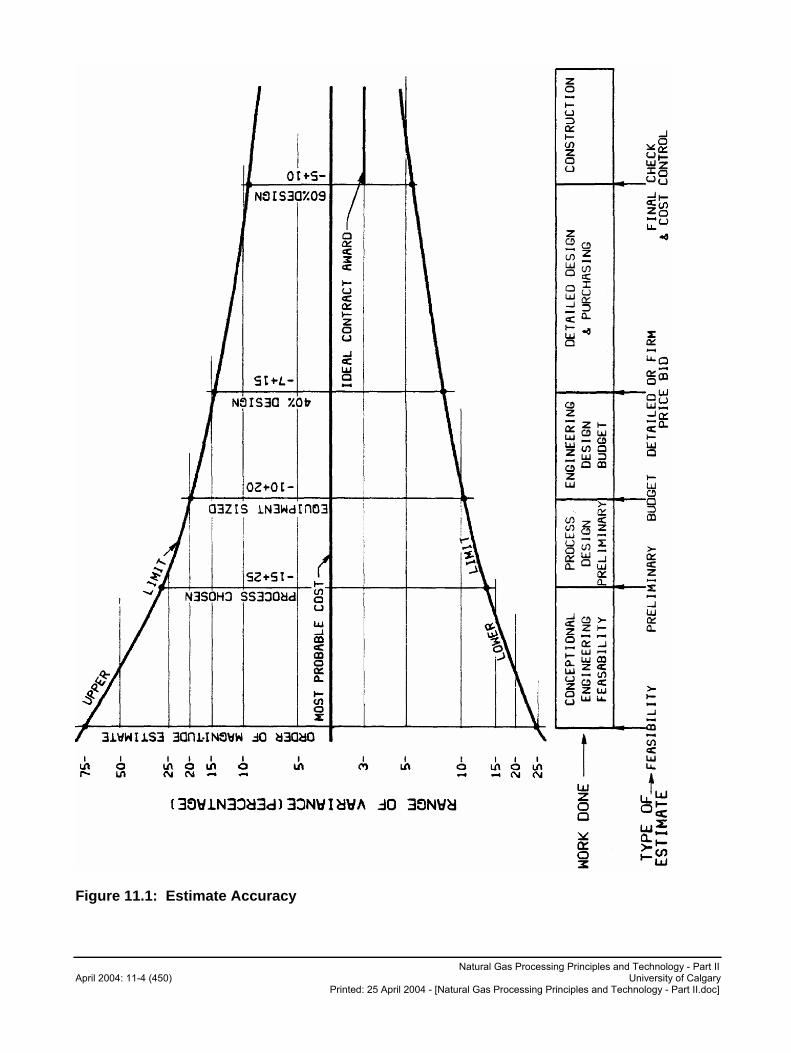
Natural Gas Processing Principles and Technology - Part II April 2004: 11-4 (450) University of Calgary
Printed: 25 April 2004 - [Natural Gas Processing Principles and Technology - Part II.doc]
Figure 11.1: Estimate Accuracy
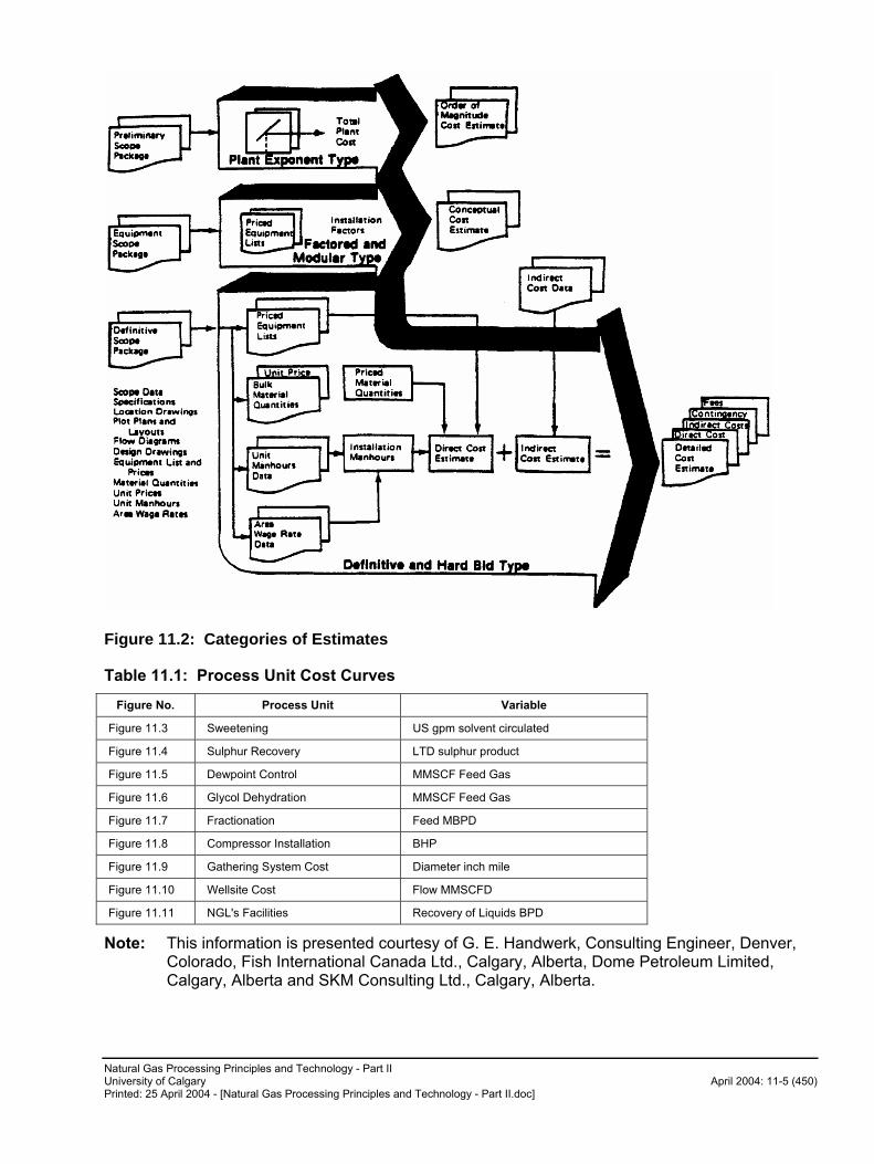
Natural Gas Processing Principles and Technology - Part II University of Calgary April 2004: 11-5 (450) Printed: 25 April 2004 - [Natural Gas Processing Principles and Technology - Part II.doc]
Figure 11.2: Categories of Estimates
Table 11.1: Process Unit Cost Curves
Figure No. Process Unit Variable
Figure 11.3 Sweetening US gpm solvent circulated
Figure 11.4 Sulphur Recovery LTD sulphur product
Figure 11.5 Dewpoint Control MMSCF Feed Gas
Figure 11.6 Glycol Dehydration MMSCF Feed Gas
Figure 11.7 Fractionation Feed MBPD
Figure 11.8 Compressor Installation BHP
Figure 11.9 Gathering System Cost Diameter inch mile
Figure 11.10 Wellsite Cost Flow MMSCFD
Figure 11.11 NGL's Facilities Recovery of Liquids BPD
Note: This information is presented courtesy of G. E. Handwerk, Consulting Engineer, Denver, Colorado, Fish International Canada Ltd., Calgary, Alberta, Dome Petroleum Limited, Calgary, Alberta and SKM Consulting Ltd., Calgary, Alberta.

Natural Gas Processing Principles and Technology - Part II April 2004: 11-6 (450) University of Calgary
Printed: 25 April 2004 - [Natural Gas Processing Principles and Technology - Part II.doc]
The year of information in the curves is given and should be adjusted to present day costs using an inflation index as indicated below.
The cost of various facilities (particularly plants) changes with time. A good way to update costs is to multiply the cost of the facility in a certain year by the ratio of the "Nelson" construction index of today's date and divide by the Nelson construction index of the date the plant is built. Therefore, if you know that a plant costs $10,000,000 in 1964, the cost for the same plant in 1976 would be:
000,362,24$257
1.626000,000,10$ �