University Lunar Construction Utility Vehicle - NASA · Old Dominion University Lunar Construction...
146
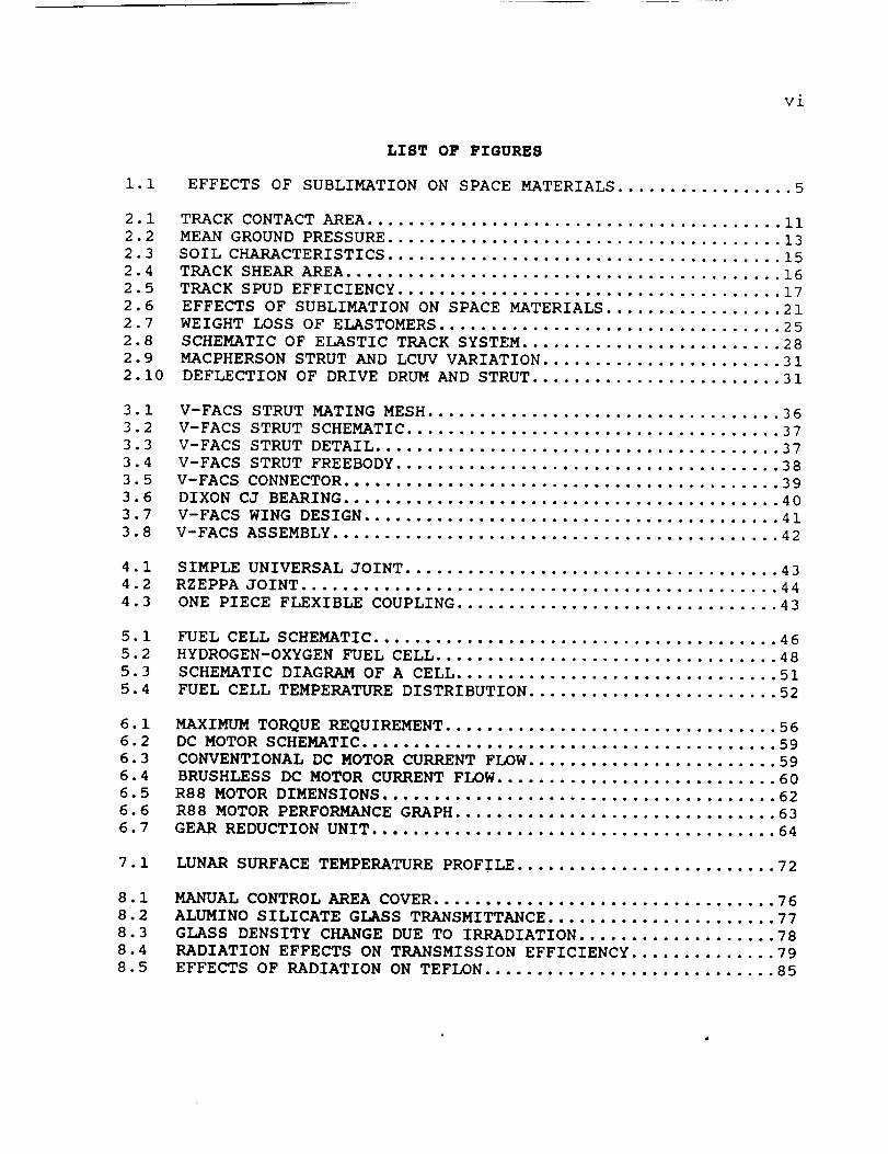
,//j /_ Old Dominion University Lunar Construction Utility 0 Vehicle _LATOR ARM F RADIATOR SECONDARY RADIATOR TENSIONER ROLLER HALOGEN • SIGNAL RECEIVER ROTATING PLATEN OMNI-DIRECTIONAL ANTENNA ELAST_ LOOP TRACK DRIVE MOTOR ACCESS PLATE Lj n_._1 _', NASA/USRA July 1989 Summer Report https://ntrs.nasa.gov/search.jsp?R=19900006119 2018-07-17T07:26:48+00:00Z
Transcript of University Lunar Construction Utility Vehicle - NASA · Old Dominion University Lunar Construction...

,//j /_
Old Dominion University Lunar Construction Utility
0
Vehicle
_LATOR ARM
F RADIATOR SECONDARY RADIATOR
TENSIONER ROLLER
HALOGEN
•SIGNAL RECEIVER
ROTATING PLATEN
OMNI-DIRECTIONAL ANTENNA
ELAST_ LOOP TRACK
DRIVE MOTOR ACCESS PLATE
Lj n_._1 _',
NASA/USRA
July 1989
Summer Report
https://ntrs.nasa.gov/search.jsp?R=19900006119 2018-07-17T07:26:48+00:00Z
FOREWORD
The lunar construction utility vehicle (LCUV) was a task
performed by a group of mechanical engineering students at Old
Dominion University during the Spring semester of 1989. The LCUV
concept was developed as part of the Advanced Space Design Program
which is managed by the University Space Research Association
(USRA). The conceptual report from which the constraints for this
design were taken is listed as reference i0 in this report. The
LCUV is a utility/construction vehicle which will aid in the
robotic assembly of a lunar outpost. The vehicle is designed to
operate during the initial unmanned (phase i) construction phase.This scenario is set in the time frame 1992-2007.
Dr. John Alred was the NASA technical manager for this study;
however, he has since taken the position of Assistant Director withthe USRA.
This report offers both conceptual and detailed analyses.
Many problems have been identified, and this work will continue for
another semester with the goal of developing the details to the
point where a scaled working model can be built and tested.
Questions concerning this report may be directed to:
Dr. Robert L. Ash
Old Dominion University
Department of Mechanical Engineeringand Mechanics
Norfolk, VA 23508
(804) 683-3720

ii
ACKNOWLEGEMENTS
This work was carried out during the spring semester of 1989.
The following students took part in the LCUV project:
TECHNICAL MANAGERS
Bill Campbell
Tony CoulsonJeff Jacobs
STUDENT ENGINEERS
Dave Alcorn
Tim Bacon
Rachelle BentleyJim Coritz
Charles Draper
Gary Dunne
Harry Hargis
Doug Henry
William HughesSalim Khaireddine
Frank Martillotti
John NagySteve Nieman
Dimitri Nunez
Paul Stiles
Greg Stoltz
Joe Szabo
Tim Taylor
Mike Zydron
Dr. John Alred was the NASA mentor for the project
Dr. Robert Ash, chairman of the Mechanical Engineering Department,
is the principal investigator for USRA projects at Old DominionUniversity.
Dr. Mason Chew is the class instructor and co-investigator for USRAprojects.
Claude Bryant was the graduate teaching assistant and technical
editor of this report.
Special thanks go to the student managers for the extra work they
put into the project.

iii
TABLE OF CONTENTS
FOREWORD ..................................................... i
ACKNOWLEDGEMENTS ............................................. ii
TABLE OF CONTENTS ............................................ iii
LIST OF FIGURES .............................................. vi
LIST OF TABLES .............................................. viii
LIST OF ABBREVIATIONS ........................................ ix
ABSTRACT ..................................................... x
1.0
i.I
1.2
1.3
1.3.1
1.3.2
1.3.3
1.3.4
1.3.5
1.3.6
1.3.7
1.4
HULL AND BODY ........................................ 1
INTRODUCTION ......................................... 1
CAD ANALYSIS ......................................... 1
MATERIALS ............................................ 2
ASSUMPTIONS AND DESIGN CONSTRAINTS ................... 3
MATERIALS FOR STRUCTURAL APPLICATION ................. 3
TEMPERATURE EFFECTS .................................. 4
VACUUM EFFECTS ....................................... 4
RADIATION EFFECTS .................................... 5
CRATERING AND PENETRATION DAMAGE ..................... 6
WELDING STRESSES ..................................... 6
CONCLUSION ........................................... 6
2.0
2.1
2.2
2.3
2.4
2.5
2.6
2.7
2.8
2.8.1
2.8.2
2.9
2.10
2.11
2.12
2.13
2.14
2.15
LOCOMOTION SYSTEM .................................... 9
ASSUMPTIONS AND DESIGN CONSTRAINTS ................... 9
INTRODUCTION ......................................... 9
SYSTEM CANDIDATES .................................... i0
LUNAR SURFACE CONDITIONS ............................. 12
BEARING CAPACITY ..................................... 12
TRACTIVE EFFORT ...................................... 14
DRAW BAR PULL ........................................ 17
MATERIALS ............................................ 18
ELASTIC LOOP ......................................... 20
GROUSERS ............................................. 22
TRACK MOBILITY SYSTEM ................................ 26
INTERNAL TRACK FRAME ................................. 28
SUSPENSION OF DRIVE DRUM ............................. 29
GROUSER DESIGN ....................................... 33
DRIVE DRUM AND PIVOT ................................. 33
TRACK PROTECTION FENDERS ............................. 34
CONCLUSION ........................................... 35
3.0
3.1
3.2
3.3
3.4
3.5
SUSPENSION CONNECTION SYSTEM ......................... 36
V-FACS STRUT ......................................... 37
V-FACS SHAFT DESIGN .................................. 38
V-FACS CONNECTOR DESIGN .............................. 39
V-FACS WING DESIGN ................................... 41
CONCLUSION ........................................... 42

4.04.14.2
5.05.15.25.35.45.55.65.7
6.06.16.1.16.1.26.1.36.1.46.1.56.26.36.46.56.6
7.07.17.1.17.1.27.1.37.1.47.1.57.2
8.08.18.1.18.1.28.1.38.1.48.28.2.18.2.28.3
9.09.19.29.39.4
PAYLOADCONNECTIONSYSTEM............................ 43CANDIDATE DESIGNS .................................... 43
CONCLUSION ........................................... 44
POWER SYSTEM ......................................... 45
INTRODUCTION ......................................... 45
HYDROGEN-OXYGEN FUEL CELL ............................ 47
VEHICLE POWER REQUIREMENTS ........................... 48
MASS FLOW RATE OF FUEL AND OXIDIZER .................. 49
ELECTRODES ........................................... 50
HEAT AND MASS TRANSFER ............................... 50
CONCLUSION ........................................... 54
ELECTRIC MOTOR DRIVE SYSTEM .......................... 55
ELECTRIC MOTOR DESIGN ................................ 55
ASSUMPTIONS AND DESIGN CONSTRAINTS ................... 55
TORQUE AND POWER REQUIREMENTS ........................ 56
AC vs DC MOTORS ...................................... 57
CONVENTIONAL vs BRUSHLESS MOTORS ..................... 58
APPLICABLE MOTORS .................................... 61
GEARING .............................................. 64
THE LUNAR DUST PROBLEM ............................... 66
THE THERMAL DISSIPATION PROBLEM ...................... 66
SOLAR RADIATION AND SOLAR FLARES PROTECTION .......... 66
CONCLUSION ........................................... 67
THERMAL CONTROL ...................................... 68
RADIATOR DESIGN ...................................... 68
HEAT REJECTION CALCULATIONS .......................... 69
CONVECTIVE HEAT TRANSFER COEFFICIENT ................. 70
EFFECTIVE SINK TEMPERATURE ........................... 71
RADIATOR WALL TEMPERATURE ............................ 73
PRIME RADIATOR AREA .................................. 73
CONCLUSION ........................................... 73
ENVIRONMENTAL CONTROL ................................ 74
CABIN DESIGN ......................................... 74
ASSUMPTIONS .......................................... 75
MATERIAL BACKGROUND .................................. 75
DESIGN DECISIONS ..................................... 81
PRESSURIZATION ....................................... 82
DUST COVER DESIGN .................................... 83
MATERIAL BACKGROUND .................................. 84
DESIGN DECISIONS ..................................... 87
CONCLUSION ........................................... 87
RADIATION SHIELDING .................................. 88
RADIATION TYPES ...................................... 88
BIOLOGICAL EFFECTS OF RADIATION ...................... 89
STRATEGIES IN RADIATION EXPOSURE ..................... 90
CONCLUSION ........................................... 91
iv

v
i0.0i0.i10.210.2.110.2.210.2.310.2.410.310.3.110.4
COMMUNICATIONSYSTEM................................. 92ASSUMPTIONSAND DESIGN CONSTRAINTS ................... 92
PHASE I COMMAND CONTROL LINK ......................... 93
PULSE MODULATION ..................................... 95
PULSE CODE MODULATIONS ............................... 96
VEHICLE ANTENNAS ..................................... 97
TRANSMITTANCE ERROR CORRECTION AND DETECTION ......... 99
PHASE II COMMAND CONTROL LINK ........................ i00
VEHICLE ANTENNAS ..................................... I00
CONCLUSIONS .......................................... i01
II.0
ii.i
11.2
11.3
11.4
11.4.1
11.4.2
11.4.3
11.4.4
11.4.5
11.4.6
11.5
11.5.1
11.6
11.7
11.8
11.9
II. I0
ii.ii
ii. 12
MECHANICAL ARM ....................................... 102
ASSUMPTIONS AND DESIGN CONSTRAINTS ................... 102
LUNAR ENVIRONMENTAL EFFECTS .......................... 104
BACKGROUND ........................................... 105
HYDRAULIC VS. ELECTRICAL ACTUATION SYSTEMS ........... 106
HYDRAULIC SYSTEMS .................................... 106
ELECTROMECHANICAL SYSTEMS ............................ 106
TEMPERATURE EFFECTS .................................. 107
MAINTENANCE STANDARDS ................................ 107
LIFTING CAPACITY ..................................... 107
SYSTEM COMPARISON .................................... 108
CONTROL OF ARM ....................................... 108
NONSERVO VS. SERVO ................................... 109
CONTROL MODES ........................................ Iii
THERMAL CONTROL ...................................... iii
OTHER CONTROLS ....................................... 112
INDIVIDUAL JOINT CONTROL ............................. 112
ATTACHMENTS .......................................... 112
HOISTING MECHANISM ................................... 113
CONCLUSION ........................................... 113
12.0
12.1
12.2
12.3
12.4
12.5
12.6
OPTICAL SYSTEM ....................................... 114
ASSUMPTIONS AND DESIGN CONSTRAINTS ................... 114
LIGHTING ARRANGEMENTS ................................ 115
CAMERAS .............................................. 117
NAVIGATION AND RANGE FINDING ......................... 117
ENVIRONMENTAL PROTECTION OF EQUIPMENT ................ 119
CONCLUSION ........................................... 120
13.0
13.1
13.2
APPENDIX A ........................................... 121
APPENDIX B ........................................... 123
APPENDIX C ........................................... 124
14.0 REFERENCES ........................................... 129
vi
i.i
2.12.22.32.42.52.62.72.82.92.10
3.13.23.33.43.53.63.73.8
4.14.24.3
5.15.25.35.4
6.16.26.36.46.56.66.7
7.1
8.18.28.38.48.5
LIST OF FIGURES
EFFECTS OF SUBLIMATION ON SPACE MATERIALS ................. 5
TRACK CONTACT AREA ........................................ ii
MEAN GROUND PRESSURE ...................................... 13
SOIL CHARACTERISTICS ...................................... 15
TRACK SHEAR AREA .......................................... 16
TRACK SPUD EFFICIENCY ..................................... 17
EFFECTS OF SUBLIMATION ON SPACE MATERIALS ................. 21
WEIGHT LOSS OF ELASTOMERS ................................. 25
SCHEMATIC OF ELASTIC TRACK SYSTEM ......................... 28
MACPHERSON STRUT AND LCUVVARIATION ....................... 31
DEFLECTION OF DRIVE DRUM AND STRUT ........................ 31
V-FACS STRUT MATING MESH .................................. 36
V-FACS STRUT SCHEMATIC .................................... 37
V-FACS STRUT DETAIL ....................................... 37
V-FACS STRUT FREEBODY ..................................... 38
V-FACS CONNECTOR .......................................... 39
DIXON CJ BEARING .......................................... 40
V-FACS WING DESIGN ........................................ 41
V-FACS ASSEMBLY ........................................... 42
SIMPLE UNIVERSAL JOINT .................................... 43
RZEPPA JOINT .............................................. 44
ONE PIECE FLEXIBLE COUPLING ............................... 43
FUEL CELL SCHEMATIC ....................................... 46
HYDROGEN-OXYGENFUEL CELL ................................. 48
SCHEMATIC DIAGRAM OF A CELL ............................... 51
FUEL CELL TEMPERATURE DISTRIBUTION ........................ 52
MAXIMUM TORQUEREQUIREMENT ................................ 56
DC MOTOR SCHEMATIC ........................................ 59
CONVENTIONAL DC MOTOR CURRENT FLOW ........................ 59
BRUSHLESS DC MOTOR CURRENT FLOW ........................... 60
R88 MOTOR DIMENSIONS ...................................... 62
R88 MOTOR PERFORMANCE GRAPH ............................... 63
GEAR REDUCTION UNIT ....................................... 64
LUNAR SURFACE TEMPERATURE PROFILE ......................... 72
MANUAL CONTROL AREA COVER ................................. 76
ALUMINO SILICATE GLASS TRANSMITTANCE ...................... 77
GLASS DENSITY CHANGE DUE TO IRRADIATION ................... 78
RADIATION EFFECTS ON TRANSMISSION EFFICIENCY .............. 79
EFFECTS OF RADIATION ON TEFLON ............................ 85
vii
I0.i10.210.310.410.5
TRANSMISSIONDELAYTIME................................... 93WAVESPECTRUM............................................. 93PULSEMODULATION.......................................... 96APPROXIMATEANTENNACOST.................................. 98LUNARHORIZONDISTANCENOMOGRAM........................... i01
Ii.i PARAMETRICMANIPULATORRELATIONSHIPS...................... 109
12.112.212.312.4
LCUVARRANGEMENTOF OPTICAL AIDS .......................... 116LASERPULSETIMING ........................................ 118CORNEROPTICAL AID ARRANGEMENT............................ 118PRELIMINARYOPTICALARRAY................................. 118

i.i
2.12.22.32.42.52.62.72.82.92.10
3.13.2
4.1
5.15.25.3
6.16.2
7.1
8.18.28.38.48.5
9.19.2
viii
LIST OF TABLES
PROPERTIES OF ALUMINUM ALLOY ........................... 8
LOCOMOTION SYSTEM DECISION MATRIX ...................... ii
LUNAR SOIL DATA ........................................ 12
COMMONLY USED SPACE MATERIALS VS TITANIUM .............. 21
RADIATION RESISTANCE OF MATERIALS ...................... 23
MATERIAL PROPERTIES OF ELASTOMERS ...................... 25
TRACK SYSTEM TYPES ..................................... 27
TRACK WIDTH AND BEARING LOADS .......................... 27
TRACTIVE EFFORT, RESISTANCE AND DRAWBAR PULL ........... 28DAMPER COMPARISON ...................................... 29
FRICTION COEFFICIENT FOR MATERIALS ..................... 30
SHAFT FORCE ANALYSIS RESULTS ........................... 39
BEARING SPECIFICATIONS ................................. 40
PAYLOAD CONNECTION DEVICE COMPARISON ................... 44
SPECIFICATIONS FOR HYDROGEN-OXYGEN FUEL CELL ........... 49
HEAT OF FORMATION VALUES ............................... 49
MASS FLOW RATES FOR HYDROGEN AND OXYGEN ................ 50
CONVENTIONAL/BRUSHLESS MOTOR COMPARISON ................ 61R88 MOTOR CHARACTERISTICS .............................. 64
HEAT DISSIPATION REQUIREMENTS .......................... 69
CABIN COVER MATERIALS .................................. 80
CABIN AREA DESIGN SUMMARY .............................. 81
CABIN AREA COVERING WEIGHTS ............................ 83
EXTRAVEHICULAR MOBILITY UNIT OUTER MATERIALS ........... 84
PROPERTIES OF TFE FLUOROCARBON YARNS ................... 86
RADIATION ENVIRONMENT ON LUNAR SURFACE ................. 89
COMPUTE YOUR OWN RADIATION DOSE ........................ 90
ii.i HYDRAULIC VS ELECTRICAL ACTUATION SYSTEMS .............. 108

LIST OF ABBREVIATIONS
ix
FOV
GPC
LCUV
LTS
MA
MCIU
MEM
NRCC
ODU
PAM
PCM
PDM
PPM
PTC
PWM
REM
RMS
RPM
USRA
- FIELD OF VIEW
- GENERAL PURPOSE COMPUTER
- LUNAR CONSTRUCTION UTILITY VEHICLE
- LUNAR TELEROBOTIC SERVICER
- MECHANICAL ARM
- MANIPULATOR CONTROLLER INTERFACE UNIT
- MECHANICAL ENGINEERING AND MECHANICS
- NATIONAL RESEARCH COUNCIL OF CANADA
- OLD DOMINION UNIVERSITY
- PULSE AMPLITUDE MODULATION
- PULSE CODE MODULATION
- PULSE DURATION MODULATION
- PULSE POSITION MODULATION
- PYRAMIDAL TRUSS CORE
- PULSE WIDTH MODULATION
- ROTEGEN EQUIVALENT MAMMAL
- REMOTE MANIPULATOR SYSTEM
- REVOLUTIONS PER MINUTE
- UNIVERSITY SPACE RESEARCH ASSOCIATION
VFACS - VERTICAL FORCE ABSORBING CONNECTION SYSTEM
ORIGINAL PAGE IS
OF POOR QUALITY
x
ABSTRACT
A NASA/USRA conceptual design for the return of man to the
moon requires that a permanent lunar base be built to accommodate
future missions. The build up of the base is to be accomplished
robotically in this scenario. A key element of the project is the
development of an all purpose construction vehicle which can serve
many functions during the base assembly. The lunar construction
utility vehicle will have the following capabilities:
-_Self supporting including repairs
- Must offload itself from a lunar lander
- Must be telerobotic and semi-autonomous
- Must be able to transport one space station common module
- Must allow for man-rated operation
- Must be able to move lunar regolith for site preparation
The design constraints for this study were taken from
reference i0 of this report. These constraints represent one
conceptual scenario which is not the only possible scenario;
furthermore the overall weight and size constraints are likely to
move upward in the next phase of the LCUV design.
This study recommends the use of an elastic tracked vehicle.
Detailed material analyses of most of the LCUV components have been
accomplished. The body frame, made of pinned truss elements, has
been stress analyzed using NASTRAN. A track connection system has
been developed; however, kinematic and stress analyses are still
required. This design recommends the use of hydrogen-oxygen fuel
cells for power. Space and volume calculations will follow in a
subsequent report. Thermal control has proven to be a problem
which may be the most challenging technically. A tentative
solution has been proposed which utilizes an onboard and towable
radiator. Detailed study of the heat dissipation requirements is
needed to finalize radiator sizing. Preliminary work on a man-
rated cabin has begun; however, this is not required during the
first mission phase of the LCUV. Finally, still in the conceptual
phases, are the communication, navigation and mechanical arm
systems. It is anticipated that most of the problems identified
in this report will be solved and a subsequent report will be
issued in July 1990.

1
1.0 HULL AND BODY
This report explains the hull/body section of LCUV-2. The
dimensions of the frame are as follows: (I) a height of 0.7m will
be used (2) a distance of 3m for the width and length will also be
employed. Initially, it was decided that Pyramidal Truss Core
(PTC) would be used as the frame; however, PTC employs welds which
NASA does not like using because of vibrations upon launch. It
then decided to use a basic truss network with the above dimensions
used. Finally, a NASTRAN/PATRAN analysis was completed using Old
Dominion University's CAD system.
i.I INTRODUCTION
Initially, PTC was incorporated into our design because of its
light weight, high strength, and ability to be easily manufactured
according to design specifications (Reference I). The Pyramidal
Truss Core consists of a layered panel that acts as a truss system
with the faces acting as the compression and tension members of the
truss (Reference i). The core of the panel acts as a diagonal
truss member. The function of the PTC panels is to carry the bulk
of the compressive and tensile stresses while the core of the PTC
acts to transfer shear (Reference 1). Unfortunately, NASA does
not like using welds, since vibrations occur at launch and thus
failure is possible. What we decided on then was a simple truss
network of bar elements connected by bolts and pins. The design
is shown in Figure 1.1 of this report section. The length and
width are each 3 meters and the height is 0.7 meters. For the
actual bar elements, a hollow square section was used (see Figure
1.2). The cross-sectional area of this element is 0.016 meters
squared. All of this data and more is tabulated in Table 1.1 of
this report. Finally, a NASTRAN/PATRAN analysis was employed for
three different loading configurations. The maximum deflection for
each case was determined to be under a millimeter, implying a
sturdy and most likely failure free design.
1.2 CAD ANALYSIS
A CAD analysis was used for the frame to determine where the
maximum deflections and stresses occurred. The CAD system used
NASTRAN/PATRAN commands. PATRAN generated the model using the
proper commands such as grid and line. In PATRAN, an analysis mode
was entered where bar elements were created. Also material, force,
and displacement cards were employed into the design. The material
of the truss used was pure aluminum. The force in each case
involved a loading of 25000 Newtons. Finally the displacement
cards were used where the vehicle is constrained, namely where the
tracks attach to the frame.
In the second phase of the CAD analysis, NASTRAN was used.
Here the NOS/VE system created the neutral file from PATRAN andhence the bulk data deck was created. Basic commands were attached

into the neutral file, these commands were employed as the case andexecutive control data decks. Finally the job was submitted anddisplacement, stress, force, bending moments, and torque recordswere created for all elements and nodes generated from the analysismode of PATRAN.
Three separate loading configurations were employed in theanalysis mode of PATRAN. Unfortunately, due to a limited supply
of paper and ink, only two of the stress and deformation plots
could be plotted and submitted within this report. The three cases
are documented as follows:
CASE I:
A load of -25000 N (y dir) was applied at the back of the
frame where a bar element was not used diagonally. The reason for
this occurrence was to provide in easy access to the power systemin the event of a breakdown. The maximum deflection occurred where
the force was applied, an excellent indicator of a rigid design.
This deflection registered -0.1624E-03 m in the y direction. No
deflection was recorded in the frame in any direction greater than
this. The stress and deformation plot is shown in Appendix D of
this report.
CASE 2:
The second analysis involved a loading configuration where the
robotic arm is located. Again, a load of -25000 N was applied
in the y direction (down). Also, the bar element deflected -
3.4196E-03 m. Again no deflections were generated greater than
this maximum one. The stress and deformation plot is shown in
Appendix D of this report.
CASE 3:
Unfortunately, the second analysis is not shown. Here, a load
of -25000 N was applied in the z direction to the front of the
frame. This simulated a case where the vehicle may run into
something. A maximum deflection again was recorded at this bar
element where the force was applied. Here, a maximum deflection was
found to be -2.00E-07 in the z direction.
1.3 MATERIALS
The material used for the construction of the LCUV plays an
important role in the design aspects associated with the frame and
loading analysis. The primary criterion in the selection of an
engineering material is the extent to which that material has the
characteristics required for the design. The frame must be
designed to couple the forces imposed by the robotic arm and to
provide sufficient support to the LCUV body. Thus, by choosing a
suitable material for its construction, the frame design could
provide a lightweight and practical solution to the structure
analysis needed for the loading specifications.
In order for the material to perform as expected, it must be

able to endure the adverse environmental conditions that exist onthe lunar surface. For example, the material will be subjected toextreme temperature gradients, low vacuum, and radiationbombardment.
In order to ensure long-lasting operation, the material usedfor the construction of the LCUV must be of long life and able towithstand the lunar environment. The failure of a frame componentdue to fatigue or loading might nullify the entire LCUV mission.Therefore, the material must exhibit the properties that willenable the LCUV to meet the required design specifications.
1.3.1 ASSUMPTIONSAND DESIGN CONSTRAINTS
Most metallic structural materials are used for load- carryingcomponents such as fuel cells, robotic arms, and crew compartments.In this type of usage, maximum strength at minimum weight isdesired. The frame of the LCUV must also be designed in order tocombat the effects of the lunar environment on the material thatwill be used for its construction. These include temperaturegradients, vacuum effects, and radiation. These three mainproblems are explained briefly below:
. Temperature - the temperature on the Moon ranges from
- 170°C to 130°C. Thus, materials must be used that
are compatible with this temperature difference.
• Radiation - there are a number of types of radiation
encountered on the lunar surface. Therefore, thematerials used for the LCUV must be immune to the
penetration of harmful gamma rays.
• Vacuum e_fects - sublimation of materials is a potential
hazard for the LCUV. At low pressure, the material used
to build the LCUV might experience evaporative losses.
Hence, the need for a material that is not susceptible
to sublimation is apparent.
The effects of cratering and penetration damage and welding
also play an important role in the choice of materials• Taking
these factors into account, the following discussion is presented
in accordance with these design specifications.
1.3.2 MATERIALS FOR STRUCTURAL APPLICATION
All high strength alloys based on magnesium, aluminum,
titanium, beryllium, and steel (principally stainless) are
potential candidate materials (Reference 2). The refractory metals
cobalt, molybdenum, tantalum, and tungsten suffer severe
disadvantages in cost and weight, when considered for structural
purposes; molybdenum and tungsten also exhibit very low
ductility.(Reference 2) Titanium is also at a disadvantage due to
its high cost. One dollar will buy 18 times as much stainless

4
steel, and 60 times as large a volume of aluminum as it would buyin titanium (Reference 4). Also, steel lacks the quality of beinglight yet strong due to its weight. Therefore, the choices willbe limited to the high strength alloys of aluminum, beryllium, andmagnesium.
1.3.3 TEMPERATUREEFFECTS
Temperature can have considerable effects on the structurewhen metals of widely different coefficients of thermal expansionare joined. The coefficient of thermal expansion is a measure ofthe amount by which the volume changes in response to a change intemperature. For example, the low coefficient of thermal expansionof beryllium compared to aluminum is a potential source of highthermal stresses when these metals are joined (Reference 2).Uncontrolled solar heating can cause excessive differential
expansion. Thus, the material used for the frame and membrane
structure will be similar, if not the same. Aluminum would be the
optimal choice of material considering its high melting point which
is much greater than the 130°C maximum temperature encountered on
the moon.(Reference 3) Table i.i lists the coefficient of thermal
expansion and the melting point for aluminum along with other
important properties.
1.3.4 VACUUM EFFECTS
At high temperatures within a vacuum, loss of material may be
of concern when considering the design of a space structure. Loss
of material by direct evaporation in the low-pressure environment
of space is insignificant for aluminum, beryllium, and titanium
(Reference 2). In the case of magnesium, evaporative losses would
be appreciable (0.004 in.) in the course of a year for a structure
above 400°F (Reference 2). This value is a maximum because the
mean temperature will not be a constant 400°F on the lunar surface.
The effects of direct evaporation are shown in Figure i.i.
Aluminum, which is thermally compatible with the temperature
gradients on the moon, seems to be the appropriate choice of
material. Although titanium is also acceptable by these standards,
aluminum is less expensive and more practical. A protective
coating can also be applied to the aluminum in order to protect
against sublimation.

i04
fo2
i0o
I0_
o
,0.4
gO6
i0 e
tcj 91.0 2.0 3.0
!000 T-_( ° K )
5
Figure i.i (Reference 2)
Effects of Sublimation on Space Materials
Protective coatings of low vapor pressure metals, or
conversion coatings such as phosphate should be used for this type
of application (Reference 2). The economics of plating are
entirely reasonable for the degree of protection needed.
1.3.5 RADIATION EFFECTS
Radiation plays an important role in the design of structures
that will be located on the lunar surface. The types of radiation
encountered on the moon are solar galactic, and extragalactic
cosmic rays, X rays and gamma rays from the Sun, solar-flare and
solar wind particles, electrons and protons of the Van Allen Belts
of trapped radiation, neutrons, and alpha particles. The design
of the structure must be able to withstand these types of
radiation. Economically speaking, aluminum would be the best
choice. Aluminum is found to be an excellent deterrent for the
penetration of gamma rays (Reference 3). Other materials could be
used, but a protective coating must be applied in order to shield
the structure from the harmful radiation. The application of a
protective coating would affect the pre-flight storage and handling
of the structure which might inhibit the ability to make
adjustments within the frame. For example, the type of coating
used might require the structure to be stored in a dust-free
chamber or sterile environment in order to prevent the
contamination of the protective film. Hence, the use of aluminum
would prevent the need for this type of pre-flight storage.
I. 3.6 CRATERINGAND PENETRATIONDAMAGE
The effects of cratering and penetration damage due to variouslunar particles are serious potential hazards. The degree of theseeffects differ for each metal. Material selection canbe based onthe structural requirements such as skin thickness of the outermembrane. Commercially, beryllium is potentially more vulnerable
to particle damage because of its brittleness (Reference 2). This
limited ability to absorb impact energy can give rise to cracking
or even shattering. Also, because of beryllium's low coefficient
of thermal expansion, it is unlikely that it would be compatible
with the aluminum parts of the frame since aluminum possesses a
much different coefficient of thermal expansion. Aluminum's
ductility, as well as its strength, presents itself as being the
primary material for the frame and outer membrane structure.
1.3.7 WELDING STRESSES
Although aluminum is a popular structural material, one of its
main weaknesses is the formation of stresses due to welding. The
welding of aluminum members will be found mostly in the frame
construction where the strength of these welds will be pertinent
to loading specifications. Most of the structural aluminum alloys
attain their strength by heat treatment or strain hardening.
Welding causes local annealing which produces a zone of lower
strength along both sides of the weld bead (Reference 5);
therefore, allowable stresses for welded members will need to be
determined so that the appropriate welds can be used to alleviate
these stresses as much as possible.
1.4 CONCLUSION
The CAD analysis was a useful tool in determining if the
vehicle could resist failure under loads of large amounts.
Fortunately, all deflections were recorded under a millimeter, thus
proving that the frame would be durable in the lunar environment.
If more time had been allowed, the next step would involve a finite
element analysis using NASTRAN/PATRAN for the plates attached tothe frame itself.
The types of materials considered for the frame construction
of the LCUV were limited to aluminum, beryllium, titanium,
magnesium, steel, and their alloys. These materials were compared
on the basis of their characteristics when exposed to the effects
of temperature, radiation, and vacuum. By studying these effects,
it was noted that aluminum seemed to be the least prone to these
conditions. Aluminum also possesses the quality of being light
weight yet very strong. Therefore, by using aluminum, the LCUV
will attain maximum strength at minimum weight at a price that is
economically reasonable.
The following is a summary of the analysis that led to thechoice of aluminum for construction of the LCUV. Aluminum waschosen from a potential group of high strength materials thatincluded magnesium, titanium, beryllium, and steel (principallystainless). The disadvantages of the use of these materials andthe advantages of aluminum are listed as follows:
Titanium - although titanium possesses the quality of
being lightweight and very strong, its price is
economically impractical.
Maqnesium - suffers appreciable evaporative losses when
exposed in a vacuum. The need for a protective coating
that will prevent sublimation might cause pre-flight
storage problems. For example, the coating might
require the frame to be stored in a temperature
controlled, dust-free chamber or sterile environment.
Beryllium - commercially, beryllium is brittle and is
potentially more vulnerable to particle damage and
cracking due to vibrations and its inability to absorb
impact energy.
Steel - although steel is strong, it is too heavy to be
used for space-bound structures.
Aluminum - its light weight and high strength is an
attractive combination for use as a space-bound
structure. Aluminum does not suffer appreciable
evaporative losses and is an effective deterrent of
harmful gamma rays. Aluminum will not be effected by
the temperature differences on the lunar surface and is
very practical and economical.
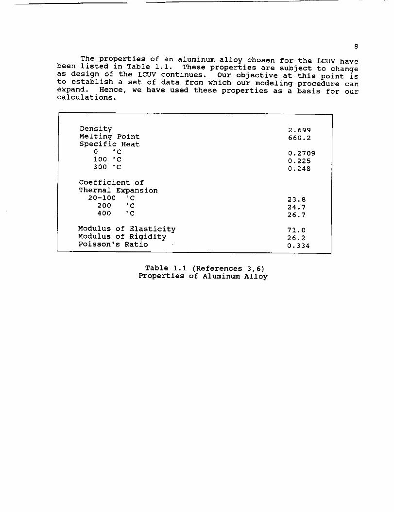
The properties of an aluminum alloy chosen for the LCUV havebeen listed in Table i.i. These properties are subject to changeas design of the LCUV continues. Our objective at this point isto establish a set of data from which our modeling procedure canexpand. Hence, we have used these properties as a basis for ourcalculations.
Density 2.699Melting Point 660.2Specific Heat
0 °C 0.2709i00 °C 0.225300 °C 0.248
Coefficient of
Thermal Expansion
20-100 °C 23.8
200 °C 24.7
400 °C 26.7
Modulus of Elasticity
Modulus of RigidityPoisson's Ratio
71.0
26.2
0.334
Table i.i (References 3,6)
Properties of Aluminum Alloy
9
2.0 LOCOMOTION SYSTEM
The following section is a detailed analysis of the locomotion
options available for the Lunar Utility Vehicle. Lunar soil
mechanics, bearing areas and gross tractive efforts will be
discussed extensively. Locomotion systems will be evaluated on
effectively meeting the presented design consideration andconstraints.
2.1 ASSUMPTIONS AND DESIGN CONSTRAINTS
The list provided below presents the design assumptions and
design constraints used in the locomotion system analysis.
- The maximum dimensions that may be used for a
propulsion system are (Reference i0):
Length=3.4 metersWidth=l meter
Height=l meter
- Initial mass of the LCUV will not exceed 7500 kg.
- Maximum mass of the LCUV, after further integration of
systems on the moon is 15,000kg.
- The locomotion system must enable the LCUV to tow the
weight of another LCUV.
- The acceleration due to gravity on the surface of the
moon is 1/6 that of the Earth's.
- The chosen system must be uncomplicated in its approach
and require minimum maintenance.
2.2 INTRODUCTION
The basic forces, design considerations and problems of trackconstruction for vehicles on earth will be similar to those on the
moon. A vehicle of adequate power moves across the ground only if
the strength of the ground is sufficient to support its weight
without much resistance to motion, and provide the thrust of the
ground involved in locomotion. The vertical and horizontalreaction forces to this motion are known as "flotation" and
"traction". In evaluation of the reaction forces and the vehicle's
overall motion characteristics, the soil properties and soil
mechanics play a major factor just as they do on the earth.
Soil and surface conditions will govern the amount of sinkage
and slip of a vehicle. Sinkage is defined as the amount of
deformation of soil due to the vehicle's weight. Slip is a
condition that occurs when the vehicle has no traction and producesno shear force on the soil. When there is little or no shear force
on the soil, there is no locomotion.
i0
One of the main reasons for applying a track to a vehicle isto provide a bearing area which would support heavy loads in softground (such as lunar soil). Thus the assessment of bearingcapacity of tracks becomes an important part of vehicle performanceand design. Two specific soil values pertaining to its strength("c" - the soil cohesion constant and "_" - the angle of internalsoil friction) play a major role in bearing capacity.
The gross tractive effort is defined as the force ofpropulsion in the horizontal direction caused by shearing strengthof soil. This force is a combination of the ground contact areaand the gross vehicle weight. The gross tractive effort will notonly determine the vehicle's performance but also the vehicle'stowing capabilities. Soil mechanics also play a key role on thevehicle's tractive effort.
2.3 SYSTEMCANDIDATES
The following list of candidates for surface locomotionsystems were considered as possibilities: wheel, jointed legs, andtrack. The requirements placed on the LCUV in terms of efficiencyin performance of assigned tasks and load mobility conditions willbe the main design criteria.
The requirements of the locomotion system being mechanicallysimple immediately eliminates the jointed leg candidate. Jointedleg locomotion systems have been shown to be extremely complex innature (Reference i0). Wheeled and track locomotion systems, theprimary types of rolling locomotion used on Earth, present the mostfavorable candidates in terms of being mechanically simple systems.A comparison of these two systems in regards to the designconsiderations and/or constraints will now follow.
Previous lunar vehicles have utilized the wheeled option withgreat success (Reference 8). Wheels are extremely reliable andmechanically efficient. The wheeled system can employ a varietyof wheel types (such as pneumatic,solid,etc) and wheel sizes;however, wheeled systems possess a limited surface contact area(Reference i0). Surface contact area is key in both themaintenance of traction under loaded conditions and navigation ofrough terrain.
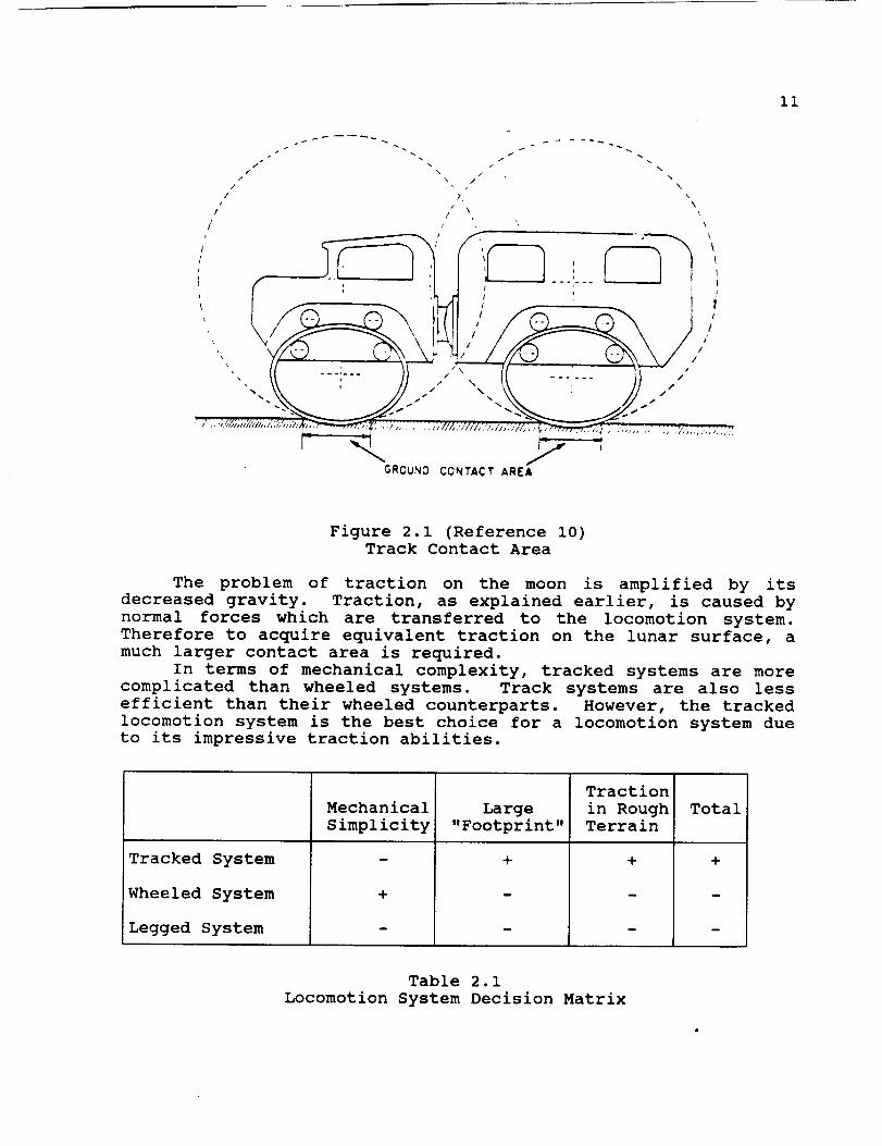
Track locomotion systems are well suited for use on the lunarsurface. As seen below in Figure 2.1, track systems have a muchbetter distribution (foot print) than that of wheels. To achievethe same surface area in contact, a wheeled system would have toutilize wheels much greater in size and weight as compared to theneed track size.
ii
s. • I n
/ -. / \/ \ / ,
/ \ /
I ,_ \k
" i_/// \\ -. -,--- //
/GROUNO CONTACT AREA
Figure 2.1 (Reference I0)
Track Contact Area
The problem of traction on the moon is amplified by its
decreased gravity. Traction, as explained earlier, is caused by
normal forces which are transferred to the locomotion system.
Therefore to acquire equivalent traction on the lunar surface, a
much larger contact area is required.
In terms of mechanical complexity, tracked systems are more
complicated than wheeled systems. Track systems are also less
efficient than their wheeled counterparts. However, the tracked
locomotion system is the best choice for a locomotion system due
to its impressive traction abilities.
Tracked System
Wheeled System
Legged System
Mechanical
Simplicity
m
+
m
Large
"Footprint"
+
Traction
in RoughTerrain
+
Total
+
Table 2.1
Locomotion System Decision Matrix
12
2.4 LUNAR SURFACECONDITIONS
Lunar surface conditions are not as diverse as those found onearth. However, there are still great variations of conditionsthat must be analyzed to fully consider all aspects Of the lunarsurface. One such condition may be roughly explained by theexistence of cohesive forces which bind soils together in numerouscomplex physical phenomena. These forces may be compared to thesticking power of glue which holds the soil particles together.This stickiness is known as the coefficient of soil cohesion "c"and is expressed in psi or kN/m2.
Soils that are loose such as sand or cold "powder" snow arenot necessarily held together by any kind of cohesive force. Theycontain loose particles that are able to move against each other.As a result, these soils create a frictional force against objectsmoving through them. This frictional force of soil is measured indegrees and is known as the angle of friction "_".
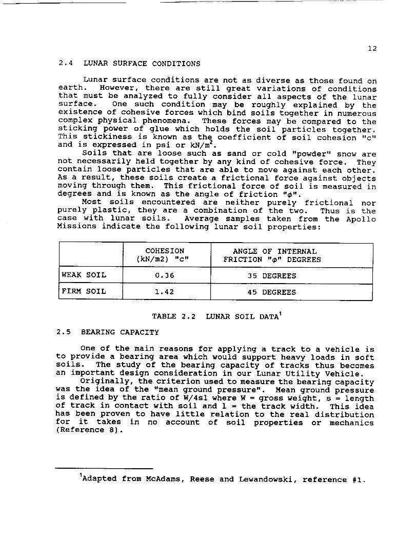
Most soils encountered are neither purely frictional norpurely plastic, they are a combination of the two. Thus is thecase with lunar soils. Average samples taken from the ApolloMissions indicate the following lunar soil properties:
COHESION ANGLE OF INTERNAL(kN/m2) "c" FRICTION "_" DEGREES
WEAKSOIL 0.36 35 DEGREES
FIRM SOIL 1.42 45 DEGREES
TABLE 2.2 LUNAR SOIL DATAI
2.5 BEARING CAPACITY
One of the main reasons for applying a track to a vehicle isto provide a bearing area which would support heavy loads in softsoils. The study of the bearing capacity of tracks thus becomesan important design consideration in our Lunar Utility Vehicle.
Originally, the criterion used to measure the bearing capacitywas the idea of the "mean ground pressure". Mean ground pressureis defined by the ratio of W/4sl where W = gross weight, s = lengthof track in contact with soil and 1 = the track width. This ideahas been proven to have little relation to the real distributionfor it takes in no account of soil properties or mechanics(Reference 8).
IAdapted from McAdams, Reese and Lewandowski, reference #i.
13
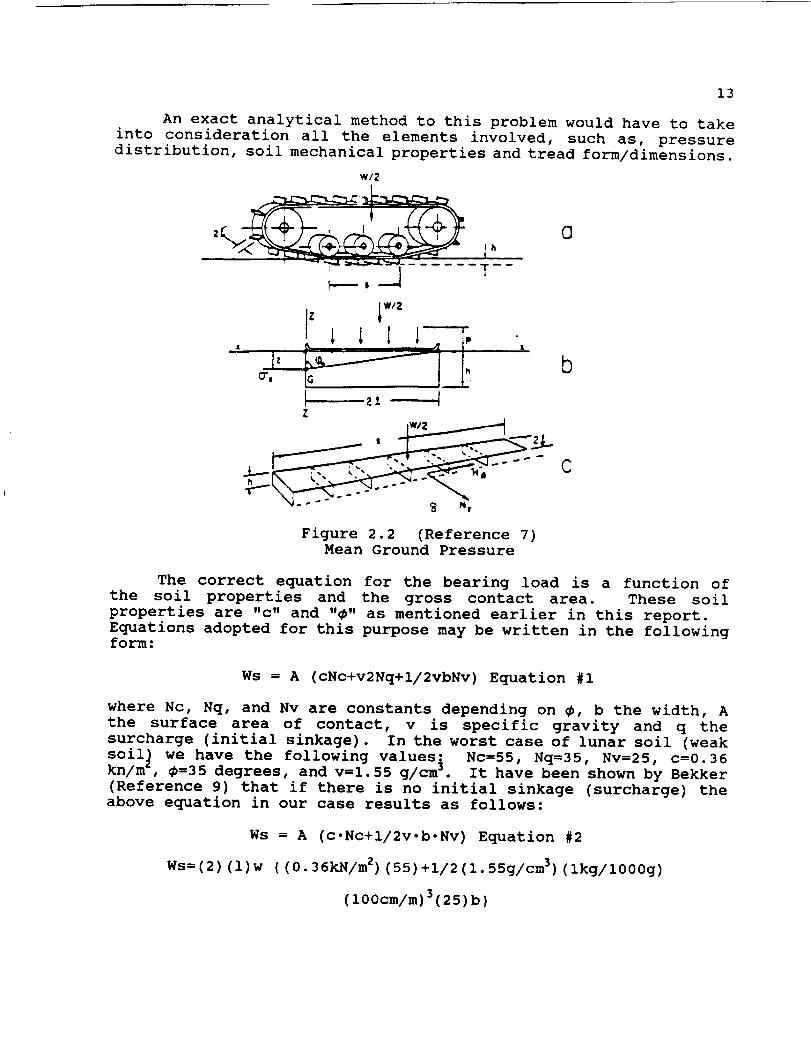
An exact analytical method to this problem would have to takeinto consideration all the elements involved, such as, pressuredistribution, soil mechanical properties and tread form/dimensions.
wi2
b
Figure 2.2 (Reference 7)Mean Ground Pressure
The correct equation for the bearing load is a function of
the soil properties and the gross contact area. These soil
properties are "c" and "@" as mentioned earlier in this report.
Equations adopted for this purpose may be written in the followingform:
Ws = A (cNc+v2Nq+i/2vbNv) Equation #i
where Nc, Nq, and Nv are constants depending on @, b the width, A
the surface area of contact, v is specific gravity and q the
surcharge (initial sinkage). In the worst case of lunar soil (weak
soil_ we have the following values: Nc=55, Nq=35, Nv=25, c=0.36kn/m _, @=35 degrees, and v=1.55 g/cm 3. It have been shown by Bekker
(Reference 9) that if there is no initial sinkage (surcharge) the
above equation in our case results as follows:
Ws = A (c.Nc+i/2v-b-Nv) Equation #2
Ws=(2)(1)w ((0.36kN/m2)(55)+i/2(l.55g/cm3) (ikg/1000g)
(lO0cm/m) 3(25) b)
14
Using two tracks and given b=O.6m, h=Im,l=3.4m from thespecifications of reference I0,
Ws = 6m2(19.8kN/m2+19. 375kN/m2)
Ws = 30,500N
In terms of mass, Wm = 18,700kg from the above equation. The
specifications for mass of the Lunar Utility Vehicle has been given
by reference i0 as Wm = 7500kg. The above equation for the mass
of the vehicle neglected the difference between the moon's
gravitational field and the earth's. It is clear that the safe
mass Wm is well above the specified mass of 7500kg
(References 8,9).
This equation neglects the difference between the moon's and
the earth's gravitational field. In terms of safe mass Wm, the
above equation yields Wm = 18,700kg. This is the maximum safe mass
which would keep the load area A on the ground surface. It is clear
that the bearing area of the given track specifications (W=0.6m,
i=3.4m) secures a safe load area. The safe mass Wm given at 7500kg
is well below the calculated safe mass (18,700 kg) for the given
load area in equations #I and #2.
2.6 TRACTIVE EFFORT
The gross tractive effort or soil thrust is caused by the
shearing strength of the soil producing a force "H" on the tracks.
The tractive effort is developed in the soil for the purpose of
propelling a vehicle. The physical description and meaning of this
may be illustrated in the following way.
The spud or cleat of a track is loaded with a vertical force
"w" identified with the weight of the vehicle. The area between
the spuds becomes packed with soil within the ground contact area
A. When the vehicle develops a maximum tractive effort, shearing
of soil occurs along this area. The force required to shear such
an area is proportional to the size of the surface area and the
soil coefficient of cohesion "c".
Because soil is normally a combination of both the purely
plastic and purely frictional soil, as shown in Figure 2.3, a
combination of those two soil properties must be included in our
analysis of tractive effort. By adding these two characteristics
and their effect on tractive effort we have the following:
Purely frictional case H=W tan
Purely cohesive case H=Ac
Equation #3
Equation #4
Combining the two the final equation is:
H=Ac+W tan Equation #5
This equation expresses the fundamental relationship between the
soil thrust (gross tractive effort "H") of the vehicle, the ground

15
contact area "A", the weight W, and the soil constants "c" and "_".(References 8,9)
@
®
©
@
Figure 2.3 (Reference 9)Soil Characteristics
There are two predominant factors in securing large tractive
efforts: track load and track size. The more frictional the soil,
the more dominant the load factor. The effect of track size
greatly increases with increasing ground cohesion. Since lunar
soil, like most, is a combination of both frictional and cohesive
particles, the design concept for the LCUV's track load and tracksize must take into account both of these characteristics.
To determine the tractive effort of our Lunar Utility Vehicle
we have the following from equations 3 and 4:
H=Ac+W tan
The worst case situation of lunar soil (weak soil) is given by:
c=0.36kN/m 2 and 0=35 degrees
The specified area of tread contact is A=21m 2, b=l.44m and the
weight W=30,500N. We therefore have the following: 2
H=(6m2) (0.36kN/m2)+(12,262.5N)(tan 35 degrees)and
2Equations by Bekker, references 8 and 9.
16
H=43,800N
The Lunar Utility Vehicle is also fully capable of favorable
tractive effort in firm lunar soils. This can be shown by the
following equation:
H=Ac+W tan
where _=45 degrees and c=l.42kN/m 2.
effort H=60,782.5N.
In this case the tractive
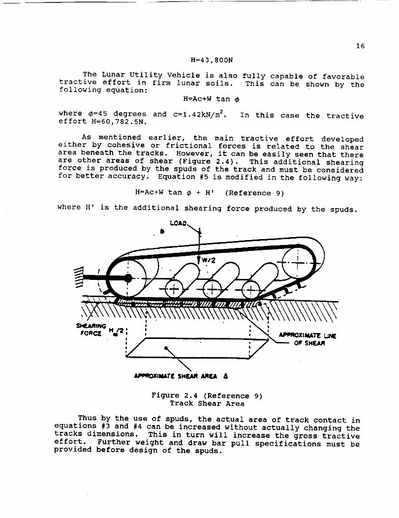
As mentioned earlier, the main tractive effort developed
either by cohesive or frictional forces is related to the shear
area beneath the tracks. However, it can be easily seen that there
are other areas of shear (Figure 2.4). This additional shearing
force is produced by the spuds of the track and must be considered
for better accuracy. Equation #5 is modified in the following way:
H=Ac+W tan _ + H' (Reference 9)
where H' is the additional shearing force produced by the spuds.
!I
! l
\LqmOXlW,ATI[ SH_ a.qF.A A
Figure 2.4 (Reference 9)
Track Shear Area
Thus by the use of spuds, the actual area of track contact in
equations #3 and #4 can be increased without actually changing the
tracks dimensions. This in turn will increase the gross tractive
effort. Further weight and draw bar pull specifications must be
provided before design of the spuds.
17
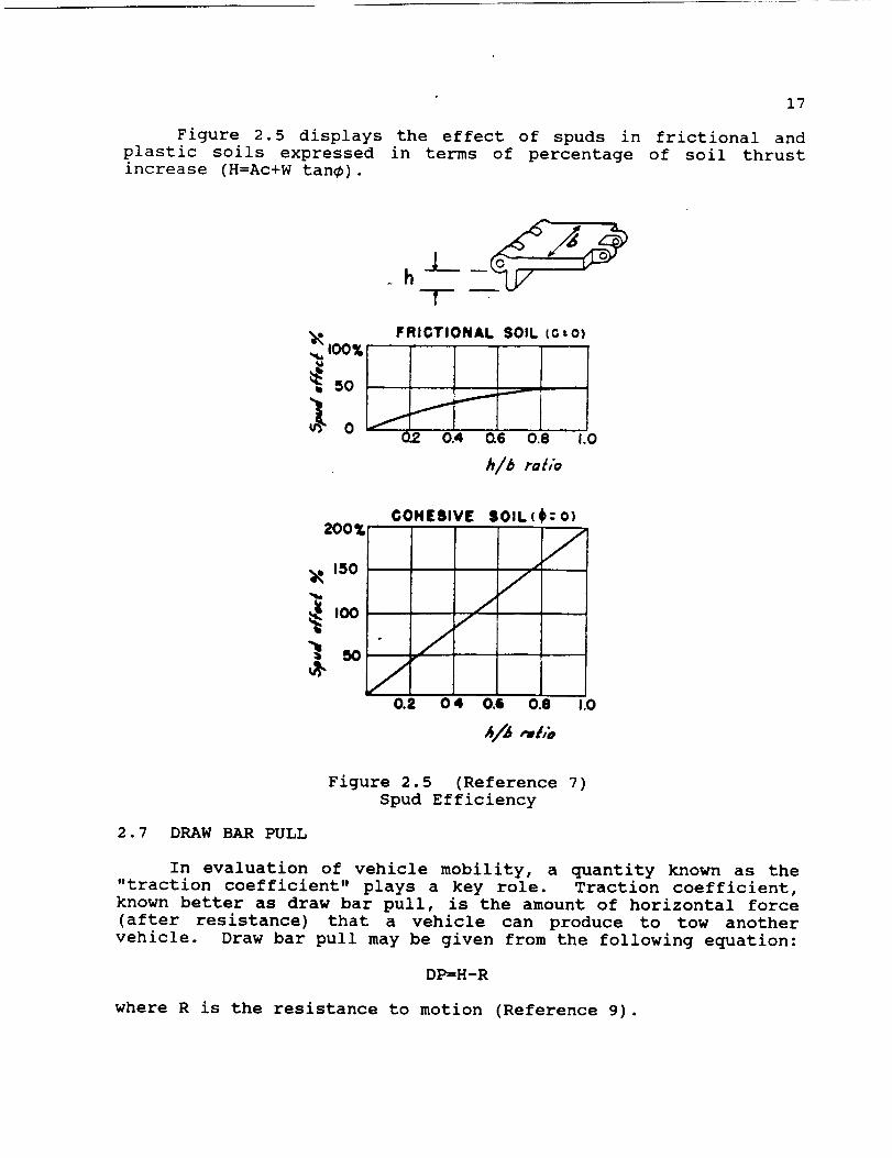
Figure 2.5 displays the effect of spuds in frictional and
plastic soils expressed in terms of percentage of soil thrustincrease (H=Ac+W tan_).
IOO%
'_ m
h-l
FRIGTIONAL SOIL (G-o)
f
f
0.4 0.6 0.8
h/b rah'o
I.O
OOHEIIVE lOlL(200_
):o)
/
I.O
Figure 2.5 (Reference 7)
Spud Efficiency
2.7 DRAW BAR PULL
In evaluation of vehicle mobility, a quantity known as the"traction coefficient" plays a key role. Traction coefficient,
known better as draw bar pull, is the amount of horizontal force
(after resistance) that a vehicle can produce to tow another
vehicle. Draw bar pull may be given from the following equation:
DP=H-R
where R is the resistance to motion (Reference 9).

18
The resistance to motion "R" is given by the followingrelation:
R= i/[ (n+l) (Kc+bKo)i/n] . (wg/L)_I/n (Reference 7)
where "L" is track length, "wg" is weight and "Kc", "Ko" and n are
soil constants (Reference 7). For the lunar surface we have the
following properties:
Ko=0.346kg/m
Kc=0.009N/m 2
n=l
The equations above yield R=3280N. Under the given specifications
of reference i0, we have (in the worst case) the following:
DP= (42,882N) - (3,2820N)
DP=40,500N
These results are for our loaded condition where the mass of
the LCUV is rated at 18,700kg. As explained earlier this is a
factor of safety designed to enable us to increase the load of the
LCUV from the guidelines of 7,500kg (Reference i0). Use of the
above draw bar and resistance equations on the given mass of
7,500kg yields the following results:
R=530N
DP=(18,200N)-(530N)
DP=I7,700N
This solution has taken into consideration the difference
between the moon's and the earth's gravitational pull. However,
it is clear that the draw bar pull in the worst case situation is
still substantial as compared to earth tractors. Our computational
results indicate that the tracked option of locomotion will more
than provide the necessary brute force to accomplish the LCUV'smission.
2.8 MATERIALS
Materials play an important role in space technologies. The
same is also true, possibly more so, for the Lunar Construction
Utility Vehicle. Materials used for the LCUV must possess high
strength. In our attempt to design materials for specific uses on
the LCUV, we have used materials that are being manufactured and
used today. This is an attempt to limit the amount of actual
material science engineering that would have to be conducted in
designing and testing "new" materials.
19
There are several environmental conditions to consider wheninvestigating materials for use in space. These significantnatural and induced environments to which space materials aresubjected are as follows:
- Galactic Radiation- Solar Ultraviolet Radiation
- Vacuum Effects
- Extreme Temperature Gradients
The first two of these environmental hazards are closely
related. Materials selected for use on the LCUV must not only help
shield radiation sensitive items, but they must also not experienceill effects from radiation. Both the ultraviolet and the soft x-
ray component of the solar spectrum possesses sufficient quantum
energy to induce rupture of many chemical bonds and thus initiate
chemical reactions (Reference 13).
The predominant types of chemical reactions taking place due
to irradiation are cross linking and chain scission
(Reference 13). Both of these processes are induced by free
radical formation and interaction resulting in structural changes
within or between adjacent chains. The effect of ultraviolet
radiation on structural metals is negligible except for a small
static charge that is produced by the slight removal of electrons.
The effects of actual molecular breakdown are predominantly seen
in polymeric materials.
Infrared and visible radiation does not possess sufficient
energy to break down molecular bonds or cause ordinary reactions.The main effect of infrared radiation is an increase in thermal
agitation experienced by the material. Even polymeric materials
experience minor effects from these types of radiation. The
effects of visible radiation are basically negligible for allmaterials and are similar to those effects of thermal radiation.
Compared to the thermal range, effects are somewhat less drastic
and basically non-existent when compared to the possible effects
in the ultraviolet range (Reference 13).
The behavior of materials in vacuum (or lunar environment) is
marked by two major effects. First, evaporation of the materials
or of a volatile component of the material is greatly enhanced by
the total lack of atmosphere. Secondly, the layer of absorbed
gases on the surfaces of many materials may be partially or
entirely removed (Reference 13).
In the case of structural metals, the evaporation of material
will pose little threat unless alkali metals are used. In the case
of plastics, those that contain a plasticizer of high vapor
pressure (cure), the loss of this constituent in the material may
cause significant property changes. Plastics formed entirely from
the polymerization of materials have lower vapor pressures and
should be considered for space applications.
The removal of conventional lubrication materials and of the
layer of absorbed gas which may act as a lubricant causes a great
increase in friction. This condition may cause severe material
2O
destruction of sliding surfaces unless special precautions arefollowed. It may be noted that on metals, however, removal of theabsorbed layer of vapor gases on most metal surfaces has abeneficial effect in inhibiting crack formations and thus increasefatigue resistance (References 12,13).
The temperature extremes on the lunar surface present a uniquevariety of problems for materials. Surface temperatures can range
from 120K to 374K (Reference i0). The changes from the high
temperatures to the low temperatures will induce cyclical thermal
stresses. Results of this temperature cycling can result in
failure due to thermal induced fatigue stresses.
Temperature can produce important effects when materials of
widely different coefficients of thermal expansion are in contact
or joined. This can be a potential source of high thermal stresses
when dealing with different thermally expanding materials.
However, careful material engineering design can easily minimize
this problem.
Thermal conductivity and resistance must also be addressed.
Materials intended to shield various parts of the vehicle from
extreme thermal gradients must possess excellent thermal resistance
properties. Materials used in thermal control of the LCUV must
possess excellent thermal conductivity properties.
2.8.1 ELASTIC LOOP
The track elastic loop must be made of a material that
possesses high durability in elastic, thermal, stress and fatigue
areas. Titanium has been recommended previously for the elastic
loop material (Reference ii) Titanium was selected because of
its high strength durability lent thermal, and excel .properties
Specifically, the Titanium alloy (Ti-5, AI-2 Sn Alpha structure),
has been recommended due to its ability to be forged into thin
sheet metal parts.
One of the main considerations in choice of a loop material
was material weight/strength ratio. Titanium is a relatively light
metal with extremely high strength. As compared to other commonly
used space metals such as aluminum alloys and nickel alloys, the
titanium alloy chosen has a higher ductility and lighter weight
(Reference 12). Titanium also has larger values of tensile and
yield strengths than most commonly used space metals.

21
TENSILEALLOY STRENGTH
YIELDSTRENGTH ELONGATION
i000 Series A1 124 MPa2000 Series A1 442 MPaAZ31B Mn 248 MPaNickel 200 Series 483 MPaTitanium (Ti-5,AI-2 Sn) 862 MPa
97 MPa 25%345 MPa 5%159 MPa 7%152 MPa 18%807 MPa 26%
Note: All quantities are average values
Table 2.3 (Reference 12)Commonly Used Space Metals Vs. Titanium
Another positive aspect of using Titanium at the material for
the elastic loop material is that it has been approved for flight
use by the George C, Marshall Space Flight Center (Reference ii).
This approval means that the material has met design criteria set
forth by NASA and is deemed "safe" for use in space.
Metals present no radiation damage problems except at
extremely high doses such as those experienced from the "back wash"
from reactor fluxes. At such doses, some embrittlement takes
place. This results in increased hardness and a decrease in creep
rate. Fatigue properties are among the least to be affected.
Because the elastic loop will not serve as a radiation shield,
titanium is a perfectly acceptable choice as a material.
All materials might expect to suffer damage to surface properties
form solar flares, however, none should show damage through img/cm 2
(Reference 13).
As explained earlier, loss of material by direct evaporation
in vacuum is a major design concern. However, loss of material by
direct evaporation in the low pressure environment of space is
insignificant for Ti and its alloys (Reference 13). The following
graph shows the sublimation or evaporation rates of some metals in
vacuum at various temperatures.
,::L\
id ! t. I I - I1.0 2+0 3 o
I000 T"(" x )
Figure 2.6 (Reference 13)
Effects of Sublimation on Space Materials
22
Loss of 0.1cm/yr of material has been shown to be asignificant loss and thus is used as a design criteria(Reference 13). Referencing this value from Figure 2.6, thetemperature at which titanium will lose 0.1cm/yr in vacuum isapproximately 1250°C (973.5 K). Temperatures on the l_nar surfacewill only reach an extreme of IO0°C (373.15K). Titanium willprovide an excellent material to combat the sublimation problem forthe elastic loop.
The main disadvantage of the use of titanium is the cost.Titanium is a very expensive metal. Titanium is usually purchasedin 25,000 Ib lots at a price of $4.00/ib (price from 1985 Reference12).
Although titanium is an expensive metal, its thermal, vacuum
and radiation resistance coupled with outstanding mechanical
properties make it an excellent choice for the elastic loop
material.
Titanium
Advantaqes Disadvantaqes
- Excellent thermal resistance
- Light weight
- Excellent Mechanical properties
- Approved for use by NASA- Suffers no ill effects from normal radiation
High cost
2.8.2 GROUSERS
The grousers (cleats) on the track should be a material that
can not only withstand extreme thermal and abrasive soil
conditions, but also to some extent perform the cushioning function
of tires. This brings into consideration the use of elastomers due
to their excellent elastic properties.
In recent years the best features of certain elastomers and
plastics have been combined in composites. This has lead to a new
generation of tougher elastomers/plastics able to withstand the
extreme conditions lunar applications. This class of elastomers
is known as synthetic rubbers.
The main danger radiation presents to elastomers is changing
or crosslinking of chemical bonds within the material. Although
all rubber is radiation sensitive, polyurethane rubbers are ranked
among the most radiation resistant as seen in table below:
ORIGINAL PAGE IS
OF POOR QUALrnf 23
I{adialion St al_illt_.,
"Hart t:.ll ._laAlmuln Dosalg¢.($1l
(Jadb
I< L_b L'C-\LEI{_
'.,'l t ov'_ -\
IF4 (Pol 3 FBA_
Kel - F
E1s_torner
Neoprene _Ce_llunte
Nitrtle (Bu:_-N'I
Se81_ts
Silicones
SE 551
SE 175
Sil_stlc l_O
Slla_tlc
30-24--;:_, •
Prec lslo_ Rubber
122-70
Preeislo_ Rubber
151-70
LS-35
RTV Sea1_n_
Polyeu_i-le5ealLnt_
PLASTICS
Teflon
KmI-F
I ,¢ In" in d,iester ml at 400 F
5 x 10⁷ m dicstcr od at 400" F
I x 10>
107
I08
1.34 x 10⁷
8.3 x I07
2 x 10⁹ u vacuum ,Lea/
1 x 10⁷ as gasket in contact
with o11 at 450" F
2 x 10⁹ U vacuum seal
1.9 x 10⁹ u vacuum seal
5 x 10⁶
107
3.,3 x 107 in.TP-4 fuel
--.° ....
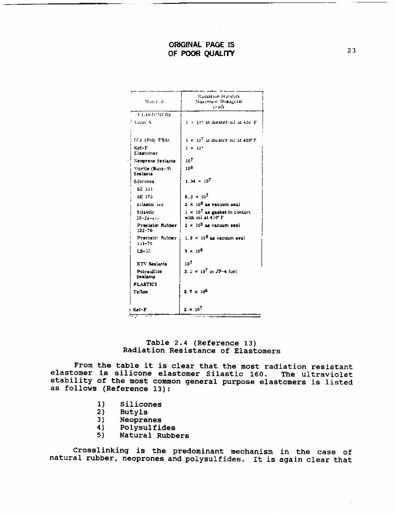
Table 2.4 (Reference 13)Radiation Resistance of Elastomers
From the table it is clear that the most radiation resistant
elastomer is silicone elastomer Silastic 160. The ultraviolet
stability of the most common general purpose elastomers is listedas follows (Reference 13):
i) Silicones
2) Butyls
3) Neoprenes
4) Polysulfides5) Natural Rubbers
Crosslinking is the predominant mechanism in the case of
natural rubber, neoprones and polysulfides. It is again clear that
24
rubbers are highly sensitive to this form of radiation. However
the resistance is still low enough to warrant damage from extreme
radiation fluxes (Reference 13). Two options to prevent damage to
the elastomer will now be presented.
First, a fender-shield of aluminum will be employed on the
LCUV to protect the track and its components (see section 2.14).
Additionally, in the case of the elastomer grousers, anti-rads may
be added to the materials. Anti-rads are organic chemical
additives that inhibit radiation damage to the materials to which
they are added. They function by preferentially absorbing the
energy induced in the compounds and releasing it thermally.
High vacuum can produce volatilization of entrapped gasses in
elastomers. The rate of evaporation of each component is a
complicated function of vapor pressure at a given temperature, the
surface to volume ratio and thickness of elastic mechanism in
question (Reference 13). The combined effects of vacuum,
temperature, and high energy penetrating radiation is to increase
the rate of evaporation. Silicone rubbers have been rated as one
of the least susceptible elastomers to the effects of radiation.
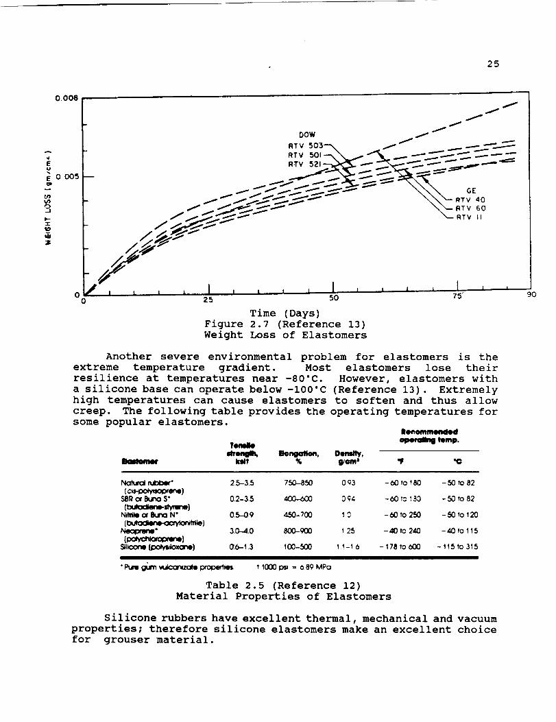
In the figure below it is clear however, that the silicone grousers
will have a decreased life due to sublimation. From the provided
graph below it is clear that some formulations of silicone
elastomers do not suffer significant weight loss even after 90 daysexposure to vacuum.
25
0.008
u
E OC_
bo
i " "
I DOW /
I RTV_03--_ _ _ _ _.....-'--'_r- RTv 5o,-.\ _. _ _ _"_ _ .-- --- --
I ....:.;,-"..--'_,.X::-_ _._c5,.'..--__ _
/ / //_ _ _ "- \\\ GE
/ / /-_- // \_ RTV 60I / _J _"'-_-_ _-- RTV II
/ //_,-t
0 0 25 50 75" 'JO
Time (Days)Figure 2.7 (Reference 13)
Weight Loss of Elastomers
Another severe environmental problem for elastomers is the
extreme temperature gradient. Most elastomers lose their
resilience at temperatures near -80°C. However, elastomers with
a silicone base can operate below -100°C (Reference 13). Extremely
high temperatures can cause elastomers to soften and thus allow
creep. The following table provides the operating temperatures for
some popular elastomers.
menlll_ llNmgaN_, Oen=_,
No_x_ rubber" 2,5-3.5 750-850 0 Q3 - 00 to _80 - 50 to 82
(c,_ene)SSR (x Burwo S" 0.2-3.5 400-b00 0 _4 - 60 t_ ;93 - 50 to 82
(bum:xJwwte-,,/,ll_}N_e Or eWJ10 N ° 0.5-0.9 450-700 10 -b0 tO 250 -50 tO 120
[ • 'te]Neo_ene" 30-4.0 800-000 125 - 40 to 240 - 40 to 115
glmone [po_k_xone] _-1.3 100-500 1 _-_ 6 - 178 to O00 - 115 to 3_5
"Pure g_n vu_-"or_zot® l:XODe_es, t 1000 ID_ = b.89 MPo
Table 2.5 (Reference 12)
Material Properties of Elastomers
Silicone rubbers have excellent thermal, mechanical and vacuum
properties; therefore silicone elastomers make an excellent choice
for grouser material.
26
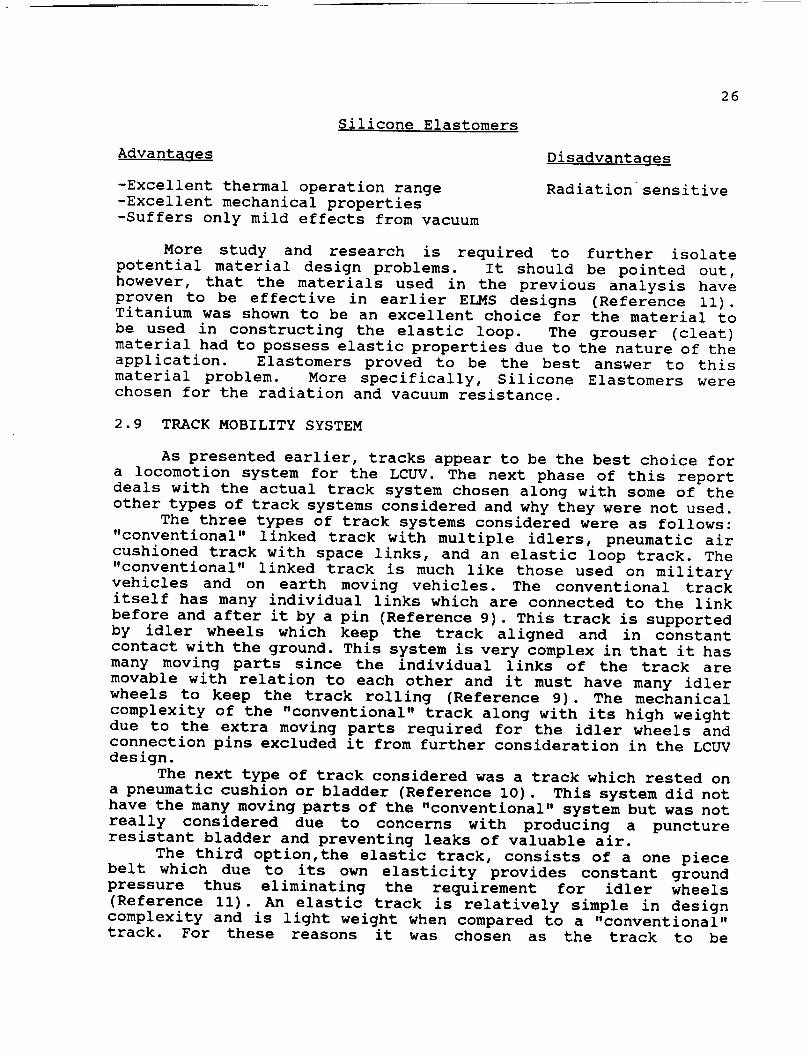
Silicone Elastomers
Advantages Disadvantages
-Excellent thermal operation range
-Excellent mechanical properties
-Suffers only mild effects from vacuum
Radiation sensitive
More study and research is required to further isolate
potential material design problems. It should be pointed out,
however, that the materials used in the previous analysis have
proven to be effective in earlier ELMS designs (Reference ii).Titanium was shown to be an excellent choice for the material to
be used in constructing the elastic loop. The grouser (cleat)material had to possess elastic properties due to the nature of the
application. Elastomers proved to be the best answer to this
material problem. More specifically, Silicone Elastomers were
chosen for the radiation and vacuum resistance.
2.9 TRACK MOBILITY SYSTEM
As presented earlier, tracks appear to be the best choice for
a locomotion system for the LCUV. The next phase of this report
deals with the actual track system chosen along with some of the
other types of track systems considered and why they were not used.
The three types of track systems considered were as follows:
"conventional" linked track with multiple idlers, pneumatic air
cushioned track with space links, and an elastic loop track. The
"conventional" linked track is much like those used on military
vehicles and on earth moving vehicles. The conventional track
itself has many individual links which are connected to the link
before and after it by a pin (Reference 9). This track is supported
by idler wheels which keep the track aligned and in constant
contact with the ground. This system is very complex in that it has
many moving parts since the individual links of the track are
movable with relation to each other and it must have many idler
wheels to keep the track rolling (Reference 9). The mechanical
complexity of the "conventional" track along with its high weight
due to the extra moving parts required for the idler wheels and
connection pins excluded it from further consideration in the LCUV
design.
The next type of track considered was a track which rested on
a pneumatic cushion or bladder (Reference I0). This system did not
have the many moving parts of the "conventional" system but was not
really considered due to concerns with producing a puncture
resistant bladder and preventing leaks of valuable air.
The third option,the elastic track, consists of a one piece
belt which due to its own elasticity provides constant ground
pressure thus eliminating the requirement for idler wheels
(Reference ii). An elastic track is relatively simple in design
complexity and is light weight when compared to a "conventional"
track. For these reasons it was chosen as the track to be
considered for the LCUV (This is shown in Table 2.6.)
27
Type
Conventional Constant Ground Pressure complex
heavy
Pneumatic light weight easily
Cushion punctured
possibly
leak
few moving parts
easily replaced
Elastic loop high
deflections
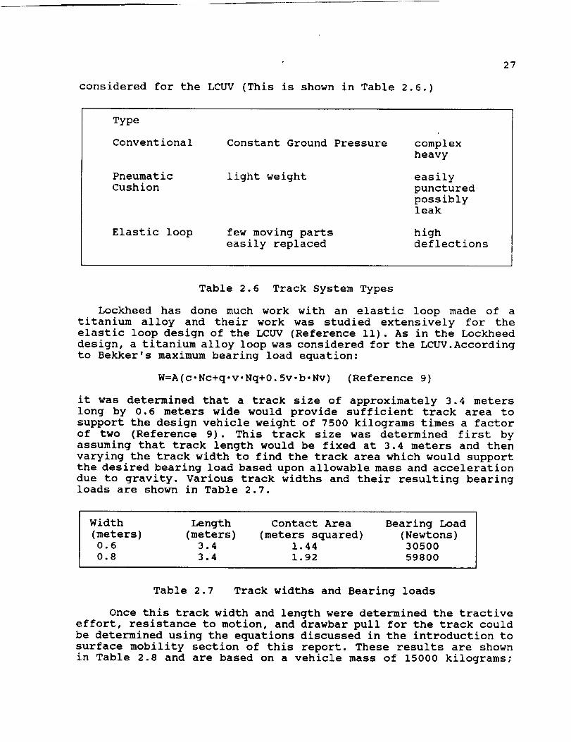
Table 2.6 Track System Types
Lockheed has done much work with an elastic loop made of a
titanium alloy and their work was studied extensively for the
elastic loop design of the LCUV (Reference ii). As in the Lockheed
design, a titanium alloy loop was considered for the LCUV.According
to Bekker's maximum bearing load equation:
W=A(c.Nc+q-v.Nq+0.5v-b.Nv) (Reference 9)
it was determined that a track size of approximately 3.4 meters
long by 0.6 meters wide would provide sufficient track area to
support the design vehicle weight of 7500 kilograms times a factor
of two (Reference 9). This track size was determined first by
assuming that track length would be fixed at 3.4 meters and then
varying the track width to find the track area which would support
the desired bearing load based upon allowable mass and acceleration
due to gravity. Various track widths and their resulting bearingloads are shown in Table 2.7.
Width Length Contact Area Bearing Load
(meters) (meters) (meters squared) (Newtons)0.6 3.4 1.44 30500
0.8 3.4 1.92 59800
Table 2.7 Track widths and Bearing loads
Once this track width and length were determined the tractive
effort, resistance to motion, and drawbar pull for the track could
be determined using the equations discussed in the introduction to
surface mobility section of this report. These results are shown
in Table 2.8 and are based on a vehicle mass of 15000 kilograms;
28
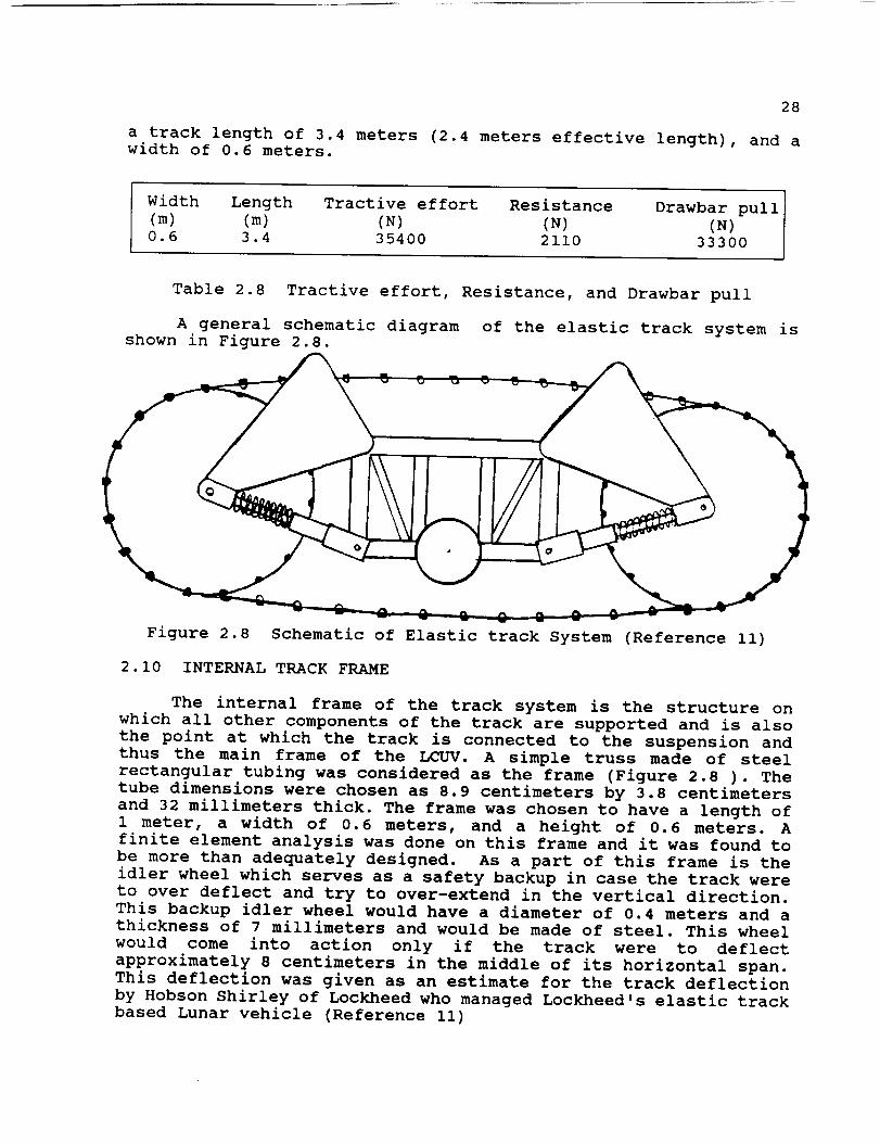
a track length of 3.4 meters (2.4 meters effective length), and awidth of 0.6 meters.
Width Length Tractive effort Resistance Drawbar pull(m) (m) (N) (N) (N)0.6 3.4 35400 2110 33300
Table 2.8 Tractive effort, Resistance, and Drawbar pull
A general schematic diagram of the elastic track system isshown in Figure 2.8.
Figure 2.8 Schematic of Elastic track System (Reference ii)
2.10 INTERNAL TRACK FRAME
The internal frame of the track system is the structure onwhich all other components of the track are supported and is alsothe point at which the track is connected to the suspension andthus the main frame of the LCUV. A simple truss made of steel
rectangular tubing was considered as the frame (Figure 2.8 ). The
tube dimensions were chosen as 8.9 centimeters by 3.8 centimeters
and 32 millimeters thick. The frame was chosen to have a length of
1 meter, a width of 0.6 meters, and a height of 0.6 meters. A
finite element analysis was done on this frame and it was found to
be more than adequately designed. As a part of this frame is the
idler wheel which serves as a safety backup in case the track were
to over deflect and try to over-extend in the vertical direction.
This backup idler wheel would have a diameter of 0.4 meters and a
thickness of 7 millimeters and would be made of steel. This wheel
would come into action only if the track were to deflect
approximately 8 centimeters in the middle of its horizontal span.
This deflection was given as an estimate for the track deflection
by Hobson Shirley of Lockheed who managed Lockheed's elastic track
based Lunar vehicle (Reference ii)
29
2.11 SUSPENSIONOF THE DRIVE DRUM
The problem of suspending the drive drum from the internalframe of the LCUV will be addressed in this section. Included inthis discussion of suspension will be sections dealing with thedamping of shocks and vibrations due to the rough Lunar surface.
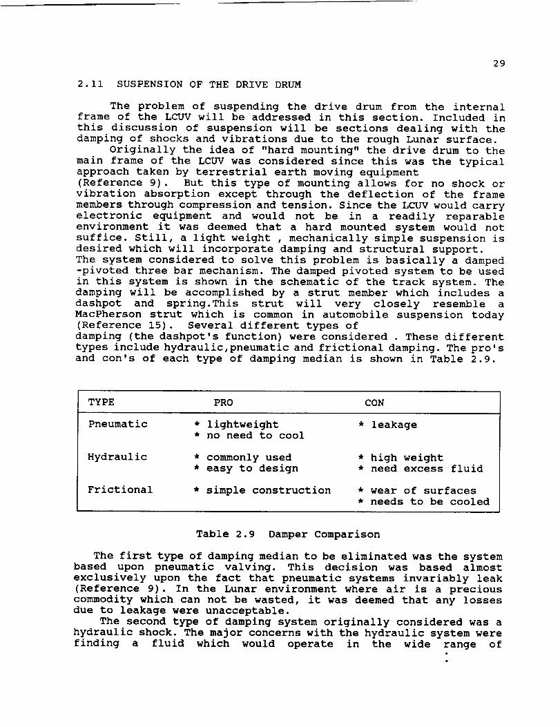
Originally the idea of "hard mounting" the drive drum to themain frame of the LCUV was considered since this was the typicalapproach taken by terrestrial earth moving equipment(Reference 9). But this type of mounting allows for no shock orvibration absorption except through the deflection of the framemembers through compression and tension. Since the LCUV would carryelectronic equipment and would not be in a readily reparableenvironment it was deemed that a hard mounted system would notsuffice. Still, a light weight , mechanically simple suspension isdesired which will incorporate damping and structural support.The system considered to solve this problem is basically a damped-pivoted three bar mechanism. The damped pivoted system to be usedin this system is shown in the schematic of the track system. Thedamping will be accomplished by a strut member which includes a
dashpot and spring.This strut will very closely resemble a
MacPherson strut which is common in automobile suspension today
(Reference 15). Several different types of
damping (the dashpot's function) were considered . These different
types include hydraulic,pneumatic and frictional damping. The pro's
and con's of each type of damping median is shown in Table 2.9.
TYPE PRO CON
Pneumatic * lightweight * leakage
• no need to cool
Hydraulic
Frictional
* commonly used
* easy to design
* simple construction
* high weight
* need excess fluid
* wear of surfaces
* needs to be cooled
Table 2.9 Damper Comparison
The first type of damping median to be eliminated was the system
based upon pneumatic valving. This decision was based almost
exclusively upon the fact that pneumatic systems invariably leak
(Reference 9). In the Lunar environment where air is a precious
commodity which can not be wasted, it was deemed that any losses
due to leakage were unacceptable.
The second type of damping system originally considered was a
hydraulic shock. The major concerns with the hydraulic system were
finding a fluid which would operate in the wide range of

30
temperatures that the LCUV would be exposed to and the higher massthat the fluid would add to the total, limited mass of the vehicle.No suitable hydraulic fluid was found although it was brieflyconsidered that the fluid used in the coolant system might beutilized as both a coolant and hydraulic fluid. This idea wasabandoned when Freon was considered as the coolant fluid, sinceFreon is not a suitable hydraulic fluid due to its thermodynamicstates during the cooling process. Failure to find a suitable fluidwas the demise of the hydraulic shock concept.
A frictional damper was chosen as the shock and vibrationabsorber. It poses no serious problems as the air and hydraulicshocks do. Items of concern with the frictional shock include heatdissipation and wear over time. The problem of heat dissipation wassolved when it was decided to incorporate a cooling system in theLCUV. Coolant lines could be run near or over the struts to keep
them cool during extended use periods when excessive heating could
occur. The problem of wear of the frictional surfaces of the damper
is not readily solved. Wear could be reduced by using a lubricant
but this would defeat the purpose of the frictional damper.
Periodic replacement of the damper will probably be the only answer
to the problem of wear. The surfaces in contact within the strutwhere friction would occur are to be metallic. For ease of
construction and to prevent problems which may arise if different
materials with different thermal expansions were used, bothfrictional surfaces will be made of the same material. The
following Table 2.10 shows different materials in contact with
themselves and their coefficients of static and moving friction.
Materials and Coefficients of Friction
Material Static coefficient Kinetic coefficient
Mild steel 0.74 0.57
Hard steel 0.78 0.42
Nickel i. I0 0.53
Aluminum 1.05 1.40
Table 2.10 (Reference 16)
Friction Coefficients of Materials
A coil spring in conjunction with the strut would be necessary
to return the strut back to its original uncompressed length after
damping has occurred and also to maintain an equilibrium position
of the strut. The coil spring in a typical automobile MacPherson
strut application surrounds the central strut (Reference 15). For
the LCUV application it would be desirable for the spring to be
located within the strut cylinder in order to help protect it from
the harsh, Lunar environment but this proved to be unfeasible due
to the large outside diameter of the coil spring. Schematics of a
typical MacPherson strut and the LCUV variation are shown in Figure
2.9.

31
Figure 2.9. MacPherson Strut and LCUV Variation
In order to design the strut assembly it was required toperform a conservation of energy analysis to find the springcoefficient required and the radial force of the fit between thetwo cylinders of the strut. The energy for the system was foundby equating the energy lost due to friction and the potentialenergy of the compressed spring with the total kinetic energy ofthe vehicle mass:
KE=0.5k.x=-u. Fx
The maximum allowable deflection was determined from thegeometry of the LCUV itself in the locations where the struts wereto be applied. With the strut installed between the drive drum andthe internal track frame, it was decided that a drive drumdeflection of i0 centimeters would be the maximum allowable so thatthe track would not come off the drive drum assembly. Thisallowable deflection of the track was an engineering guess madewith the assistance of Hobson Shirley from Lockheed (Reference Ii).From the track geometry it was found that this produces adeflection for the strut of 15 centimeters (shown in Figure 2.10).
pRAME
Figure 2.10 Deflection of Drive Drum and Strut

32
Assuming that a worst case shock to the drive drum would occurif the vehicle ran into a stationary object at full speed (0.6meters per second) the energy that the shock would have todissipate through friction and displacement changes would be dueto the kinetic energy of the vehicle. The kinetic energy was foundfrom the following equation:
KE = 0.5.m.v'
where the (m) is mass of the vehicle and (v) is the maximumvelocity. The kinetic energy of the vehicle is 300 joules assuminga total mass of 15000 kilograms. The strut has to dissipate halfthis energy through the spring energy and the work lost to thefrictional surfaces. In determining the work lost to friction anormal force had to be determined for the strut assembly. Thisforce would be due to the radial force created by forcing the innerrod of the strut into the outer cylinder of the strut. The fitwould have to be a tight fit in order to keep the surfaces of thecylinders in contact with each other. If this fit is considered asa press fit the radial pressure can be determined from thefollowing equation:
p = E-d [ (c-b) (b-a)/(2b- (c-a)) ] (Reference 6)
where (E) is the Young's modulus of the material, (d) is theinterference of the fit, (c) is the radius of the outside cylinder,(b) is the radius of the inner cylinder, and (a) is zero for thiscase. For mild steel ,a value of 207 GPa was used for Young'smodulus, I*IOA-8 meters for the interference, (c) was 3centimeters, and (b) was 2 centimeters (Reference 6). These valuesproduced a radial pressure of 2900 Pa. This radial pressure wasthen assumed to produce normal forces to the cylinders which andcould be determined by multiplying the average contact area betweenthe two cylinders by the radial pressure. To find the averagecontact area it was assumed that the strut would change in lengthby 15 centimeters at full deflection which would cause the drivedrum to move horizontally i0 centimeters. These values weredetermined by assuming that the drive drum would have a radius of0.5 meters and would be a horizontal distance of 0.2 meters fromthe internal frame. The shock was also assumed to have an originalnested length of 20 centimeters so that if the shock were to beextended out it would not pull apart. Using these distances the
normal force to the cylinder was found to be 990 Newtons.
Using conservation of energy, and assuming that all the impact
energy is dissipated through the spring and friction, the spring
constant was found to be 19 I00 N/m. Using this value of spring
rate and using an outside diameter of 5 centimeters for the spring
and going to load and spring rate tables
(Reference 16), the wire diameter of the coil spring was determined
to be 7 mm. The number of active coils for the spring could be
determined by using the following relation:
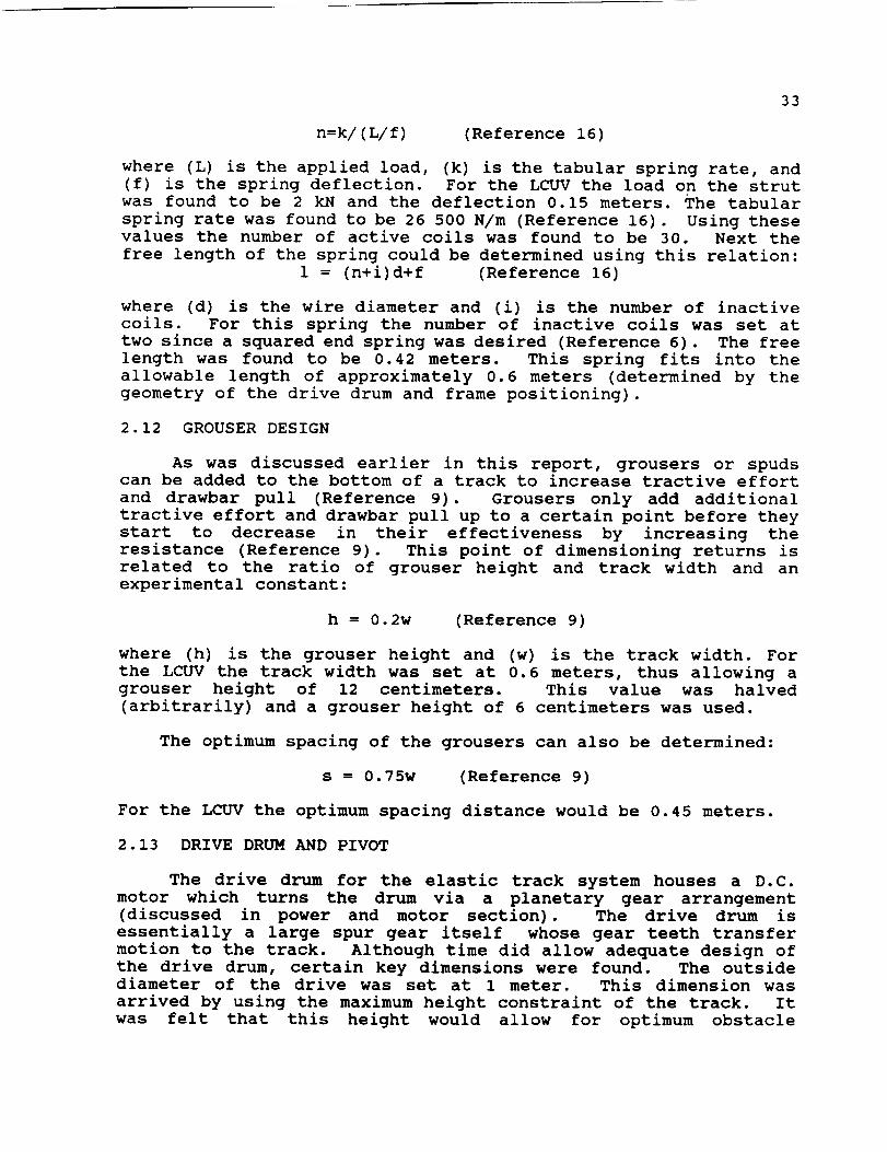
33
n=k/(L/f) (Reference 16)
where (L) is the applied load, (k) is the tabular spring rate, and(f) is the spring deflection. For the LCUV the load on the strutwas found to be 2 kN and the deflection 0.15 meters. The tabularspring rate was found to be 26 500 N/m (Reference 16). Using thesevalues the number of active coils was found to be 30. Next the
free length of the spring could be determined using this relation:
1 = (n+i)d+f (Reference 16)
where (d) is the wire diameter and (i) is the number of inactive
coils. For this spring the number of inactive coils was set at
two since a squared end spring was desired (Reference 6). The free
length was found to be 0.42 meters. This spring fits into the
allowable length of approximately 0.6 meters (determined by the
geometry of the drive drum and frame positioning).
2.12 GROUSER DESIGN
As was discussed earlier in this report, grousers or spudscan be added to the bottom of a track to increase tractive effort
and drawbar pull (Reference 9). Grousers only add additional
tractive effort and drawbar pull up to a certain point before they
start to decrease in their effectiveness by increasing the
resistance (Reference 9). This point of dimensioning returns is
related to the ratio of grouser height and track width and an
experimental constant:
h = 0.2w (Reference 9)
where (h) is the grouser height and (w) is the track width. For
the LCUV the track width was set at 0.6 meters, thus allowing a
grouser height of 12 centimeters. This value was halved
(arbitrarily) and a grouser height of 6 centimeters was used.
The optimum spacing of the grousers can also be determined:
s = 0.75w (Reference 9)
For the LCUV the optimum spacing distance would be 0.45 meters.
2.13 DRIVE DRUM AND PIVOT
The drive drum for the elastic track system houses a D.C.
motor which turns the drum via a planetary gear arrangement
(discussed in power and motor section). The drive drum is
essentially a large spur gear itself whose gear teeth transfer
motion to the track. Although time did allow adequate design of
the drive drum, certain key dimensions were found. The outsidediameter of the drive was set at 1 meter. This dimension was
arrived by using the maximum height constraint of the track. It
was felt that this height would allow for optimum obstacle

34
negotiation without requiring the track to pivot. The width ofthe drum would be 0.6 meters matching that of the track. Thethickness and material were never determined.
Design of the pivot on which the drive drum, frame, andretaining roller are to be mounted was not completed (other thanrequired lengths and a general shape). The length of the pivot armbetween the internal frame and the center of the drive drum wasdetermined to be a minimum of 0.76 meters. Extra length would haveto be added for mounting purposes. The length between theretaining roller and the internal frame is to be a minimum of 0.35meters. The length between the retaining roller and the center ofthe drive drum would have to be a minimum of 0.8 meters. Thegeneral shape of the pivot arm can be seen in the previousschematic of the track assembly.
2.14 TRACK PROTECTIONFENDERS
Track performance is a necessary requisite for the success ofthe LCUV mission. In order for the LCUV to perform as expected,the track system must be able to combat the harsh environmentalconditions that exist on the lunar surface. These include theeffects of large temperature variations and gradients, radiation,and subsequent sublimation due to the vacuum environment. The needto protect the track from dust is also apparent due to the factthat dust particles could damage the drive drums and mechanicalsettings that exist within the frame of the track system.
The track consists of a titanium belt that will needprotection from the lunar environment in order for it to operateas expected. A majority of this protection will be accomplished
by the use of a fender arrangement that will be attached to the
body of the LCUV. The fender will extend from above the track,
covering the titanium belt and shielding approximately half of the
drive drum (0.5 m). The main purpose of the fenders is to shield
the titanium track from the harmful gamma rays that will lead toeventual sublimation and corrosion of the belt itself. The fenders
will also provide ample protection from the effects of dust
particles on the track system. By regulating the flow of dust
particles around the LCUV, the cameras will not be subjected to
poor visibility; therefore, the use of fenders for the LCUV will
serve three main purposes. They can be listed as follows:
l. To provide protection from the penetration of harmful
gamma rays within the titanium belt.
2. To provide dust protection for the track's moving parts.
3. To regulate the flow of dust particles around the LCUV.
35
2.15 CONCLUSION
A tracked Lunar Utility Vehicle will be required by NASA when
it looks to inhabit the moon. Tracked locomotion systems will not
only prove to be feasible, but they will be an efficient mode of
locomotion for Lunar construction vehicles; furthermore, the design
concepts and specifications put forth by the NASA/USRA summer
report (Reference i0) have been met by the tracked locomotion
system.
In terms of bearing area requirements, draw bar pull, gross
tractive effort and minimum slip conditions (slip < = 40%), the
LCUV design characteristics must be further studied to determine
an exact array of values for various loads towed, surface
conditions and vehicle properties. Once these assessments have
been made, further design in the locomotion system can be
completed.
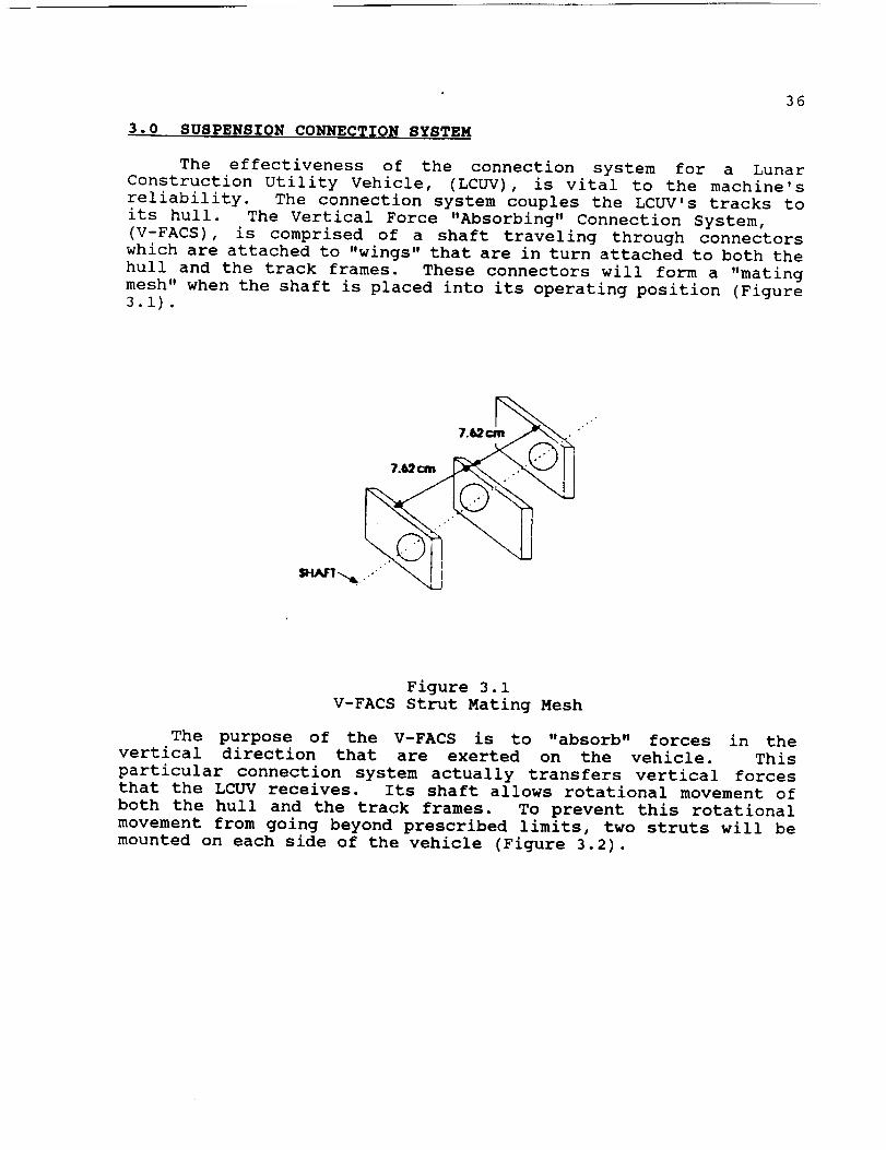
36
3.0 SUSPENSION CONNECTION SYSTEM
The effectiveness of the connection system for a Lunar
Construction Utility Vehicle, (LCUV), is vital to the machine's
reliability. The connection system couples the LCUV's tracks to
its hull. The Vertical Force "Absorbing" Connection System,
(V-FACS), is comprised of a shaft traveling through connectors
which are attached to "wings" that are in turn attached to both the
hull and the track frames. These connectors will form a "mating
mesh" when the shaft is placed into its operating position (Figure
3.1).
Figure 3.1
V-FACS Strut Mating Mesh
The purpose of the V-FACS is to "absorb" forces in the
vertical direction that are exerted on the vehicle. This
particular connection system actually transfers vertical forces
that the LCUV receives. Its shaft allows rotational movement of
both the hull and the track frames. To prevent this rotational
movement from going beyond prescribed limits, two struts will be
mounted on each side of the vehicle (Figure 3.2).

37
EX_(_G(3_11_ VBW
BES_.
I'IULL/6OOY
Figure 3.2V-FACS Strut Schematic
3.1 V-FACS STRUT
The struts will follow the same design format as the struts
that are located in the track frames. They will be similar to the
MacPherson struts except for the damping. Whereas the MacPherson
strut uses hydraulic damping, these struts will use frictional
damping. The MacPherson strut's damping depends on velocity. The
V-FACS strut will depend on distance of travel. A more detailed
sketch of the V-FACs strut may be seen in Figure 3.3.
Figure 3.3
V-FACS Strut Detail

38
3.2 V-FACS SHAFT DESIGN
Since the primary loads on the LCUV act predominantly on theshaft of the V-FACS, its design must be reliable.
For LCUV#2, the V-FACS shaft length, on both sides of thevehicle, will be 0.9144 m. This length is a design restriction inthat the track's framework is only 1 m long. It would beundesirable to design a shaft longer than is necessary. The V-FACSshaft will be made of solid aluminum with a diameter of 5.08 cm.There will be holes for pin inserts drilled and threaded on eachend of the shaft.
This particular V-FACS shaft design was chosen over solid andhollow shaft designs of carbon steel. The aluminum shaft waschosen over the carbon steel shaft because of the 7500 kg weightconstraint placed on the entire LCUV.
A stress analysis was performed using a 0.064 cm deflectionas one of the design constraints (Reference 6). The solid aluminumshaft was found to yield a greater deflection than that of thesolid and hollow steel shafts (Figure 3.4, Table 3.1);
--4_Z
A C
Ymo(- _ deflectl_I. rnorrmnt o/Inert_E • Young'srnoduUF- _ forcen- toc_ of mfohrI- k.o_',(]5.24cm)
RI-R2- moctton tatc:_
RI R2
Ym_- _b_EN(_2+_2-_2)
Figure 3.4
V-FACS Shaft Freebody
however, the solid aluminum shaft still falls within the 0.064 cm
design criteria, and is considerably lighter in weight than the
previously mentioned shafts. Its difference in maximum deflection
is so small as compared to that of the hollow steel (Table 3.1),
that it was chosen mainly because it weighs less.
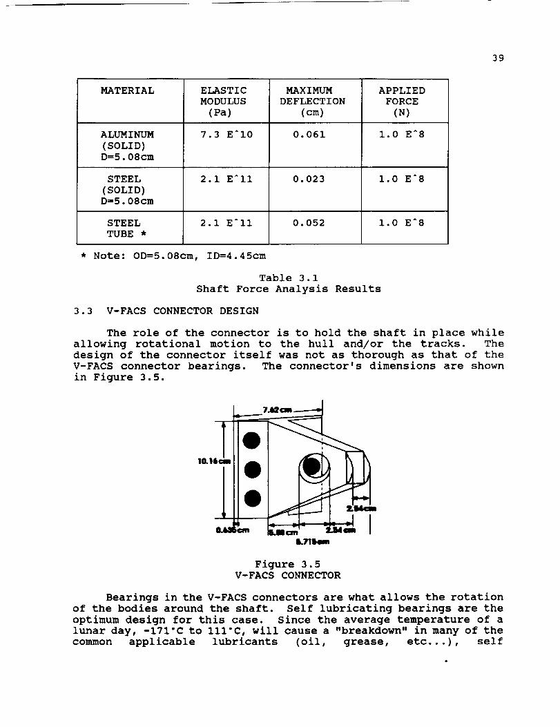
39
MATERIAL
ALUMINUM(SOLID)D=5.08cm
STEEL(SOLID)D=5.08cm
STEELTUBE *
ELASTICMODULUS
(Pa)
7.3 EAI0
2.1 EAII
2.1 EAII
MAXIMUMDEFLECTION
(cm)
0.061
0.023
0.052
APPLIED
FORCE
(N)
1.0 EA8
1.0 E_8
1.0 E_8
* Note: OD=5.08cm, ID=4.45cm
Table 3.1
Shaft Force Analysis Results
3.3 V-FACS CONNECTOR DESIGN
The role of the connector is to hold the shaft in place while
allowing rotational motion to the hull and/or the tracks. The
design of the connector itself was not as thorough as that of the
V-FACS connector bearings. The connector's dimensions are shown
in Figure 3.5.
Figure 3.5
V-FACS CONNECTOR
Bearings in the V-FACS connectors are what allows the rotation
of the bodies around the shaft. Self lubricating bearings are the
optimum design for this case. Since the average temperature of a
lunar day, -171°C to Ill'C, will cause a "breakdown" in many of the
common applicable lubricants (oil, grease, etc...), self
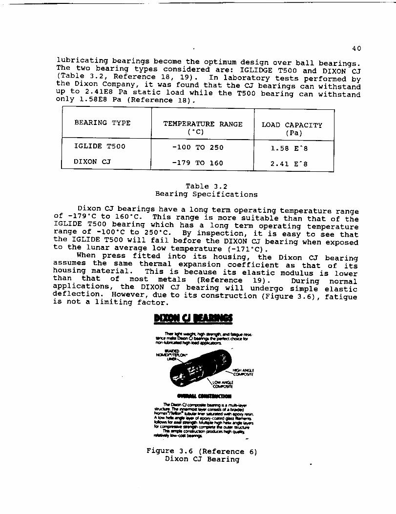
40
lubricating bearings become the optimum design over ball bearings.The two bearing types considered are: IGLIDGE T500 and DIXON CJ(Table 3.2, Reference 18, 19). In laboratory tests performed bythe Dixon Company, it was found that the CJ bearings can withstand
up to 2.41E8 Pa static load while the TS00 bearing can withstand
only 1.58E8 Pa (Reference 18).
BEARING TYPE
IGLIDE T500
DIXON CJ
TEMPERATURE RANGE
(°C)
-i00 TO 250
-179 TO 160
LOAD CAPACITY
(Pa)
1.58 EA8
2.41 EA8
Table 3.2
Bearing Specifications
Dixon CJ bearings have a long term operating temperature range
of -179°C to 160"C. This range is more suitable than that of the
IGLIDE T500 bearing which has a long term operating temperature
range of -100°C to 250°C. By inspection, it is easy to see that
the IGLIDE T500 will fail before the DIXON CJ bearing when exposed
to the lunar average low temperature (-171°C).
When press fitted into its housing, the Dixon CJ bearing
assumes the same thermal expansion coefficient as that of its
housing material. This is because its elastic modulus is lower
than that of most metals (Reference 19). During normal
applications, the DIXON CJ bearing will undergo simple elastic
deflection. However, due to its construction (Figure 3.6), fatigue
is not a limiting factor.
O EAmNm
it?-_'/]4 $_--_ff_,
nwm_.O _ _. a mu_4_
A _w h_ mp _ o__ay<oa_ gim M_m_
Figure 3.6 (Reference 6)
Dixon CJ Bearing
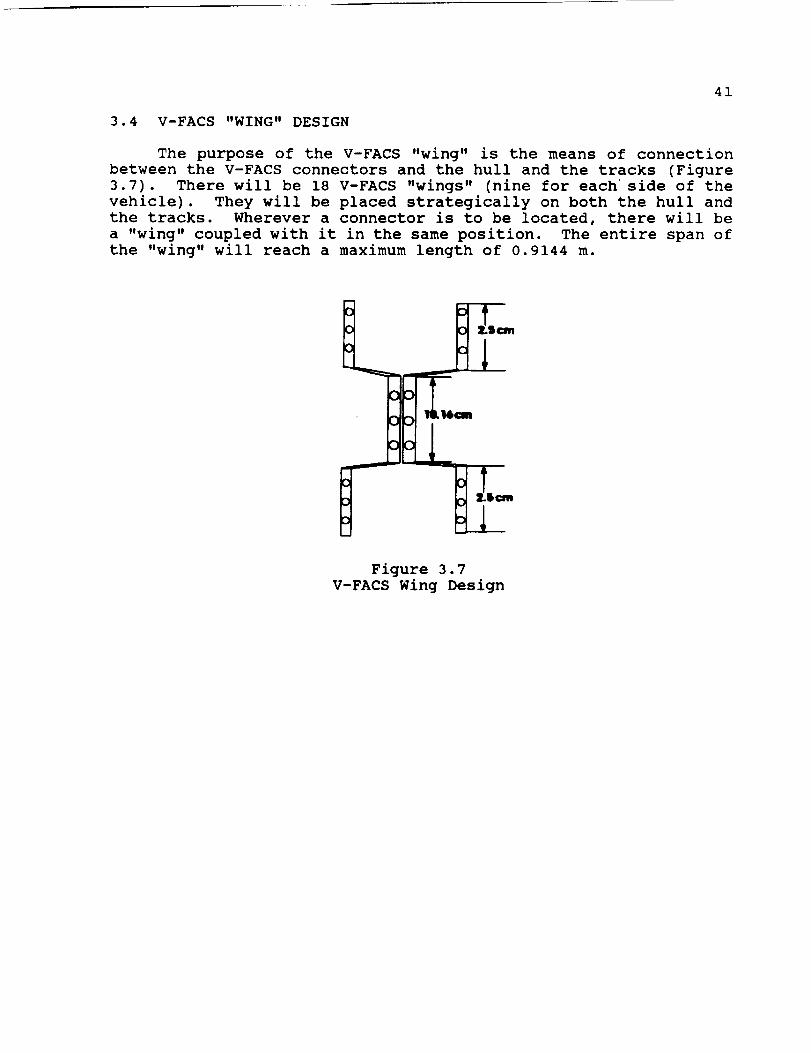
41
3.4 V-FACS "WING" DESIGN
The purpose of the V-FACS "wing" is the means of connectionbetween the V-FACS connectors and the hull and the tracks (Figure3.7). There will be 18 V-FACS "wings" (nine for eachside of thevehicle). They will be placed strategically on both the hull andthe tracks. Wherever a connector is to be located, there will bea "wing" coupled with it in the same position. The entire span ofthe "wing" will reach a maximum length of 0.9144 m.
Figure 3.7V-FACS Wing Design
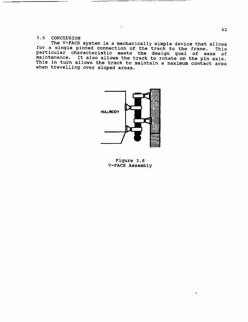
42
3.5 CONCLUSIONThe V-FACS system is a mechanically simple device that allows
for a single pinned connection of the track to the frame. Thisparticular characteristic meets the design goal of ease ofmaintenance. It also allows the track to rotate on the pin axis.This in turn allows the track to maintain a maximum contact areawhen travelling over sloped areas.
Figure 3.8V-FACS Assembly

43
4.0 PAYLOAD CONNECTION
The payload connection system couples the LCUV hull with the
hull of the payload. As a design requirement, the payload must be
able to swivel both horizontally and vertically at the coupling.
4.1 CANDIDATE DESIGNS
Three coupling devices serve as possible candidates. The
universal joint, the rzeppa joint, and the one piece flexible
coupling (Reference 20, 21). An illustration of each may be seenin Figure 4.1, 4.2, and 4.3.
----------r--.
Figure 4.1
Simple Universal Joint
B_dl W_JmGS
AWAYOF C_2VHtS
Figure 4.2
Rzeppa Joint
Figure 4.3
One Piece Flexible Coupling
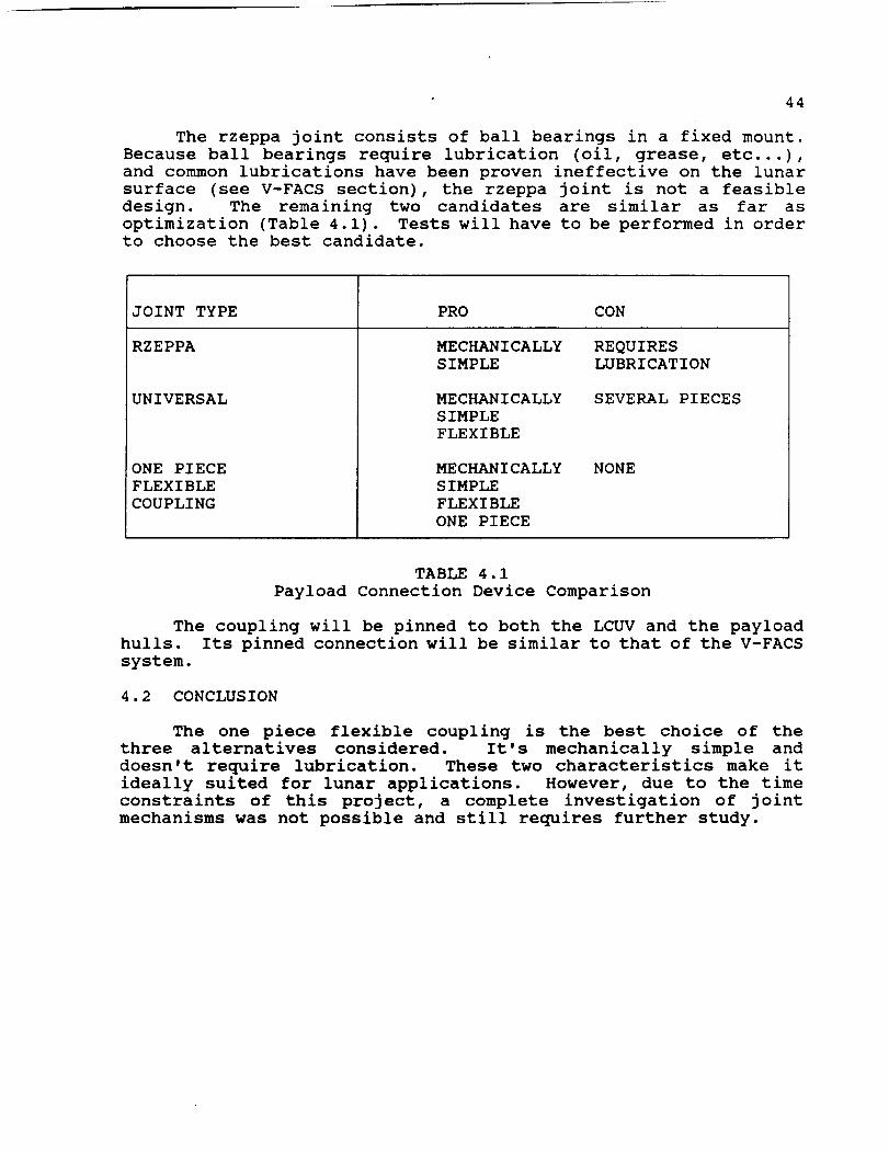
44
The rzeppa joint consists of ball bearings in a fixed mount.Because ball bearings require lubrication (oil, grease, etc...),and common lubrications have been proven ineffective on the lunarsurface (see V-FACS section), the rzeppa joint is not a feasibledesign. The remaining two candidates are similar as far asoptimization (Table 4.1). Tests will have to be performed in orderto choose the best candidate.
JOINT TYPE
RZEPPA
UNIVERSAL
ONE PIECEFLEXIBLECOUPLING
PRO CON
MECHANICALLYSIMPLE
REQUIRESLUBRICATION
MECHANICALLYSIMPLEFLEXIBLE
SEVERAL PIECES
MECHANICALLYSIMPLEFLEXIBLEONE PIECE
NONE
TABLE 4.1Payload Connection Device Comparison
The coupling will be pinned to both the LCUV and the payload
hulls. Its pinned connection will be similar to that of the V-FACS
system.
4.2 CONCLUSION
The one piece flexible coupling is the best choice of the
three alternatives considered. It's mechanically simple and
doesn't require lubrication. These two characteristics make it
ideally suited for lunar applications. However, due to the time
constraints of this project, a complete investigation of joint
mechanisms was not possible and still requires further study.

45
5.0 POWER SYSTEM
A large number of power supply systems are under development
today. Some of these systems are at an advanced stage and would
be considered good candidates for lunar application. The hydrogen-
oxygen fuel cell is an excellent choice for the power supply system
on the Lunar Construction Utility Vehicle. This report focuses on
the design characteristics of the fuel cell. In addition,
equations are included to analyze parametrically the fuel cell
response to alterations in the operating conditions.
5.1 INTRODUCTION
Electricity is the most convenient form of energy. It is easy
to control and to convert into other energy forms. Traditionally,
the production of electricity involves the combustion of fossil
fuel to release thermal energy which is converted into mechanical
energy in a heat engine (Reference 22). This conversion process
transforms energy that is stored in a highly ordered manner in the
chemical bonds to energy associated with great disorder after the
combustion process. The maximum useful power that can be obtained
from this energy, is the amount which a Carnot engine would obtain
operating between the temperature at which the energy was released
and the natural temperature of the surroundings (Reference 23).
By means of fuel cells, it is possible to bypass the
conversion-to-heat process and the associated mechanical-to-
electrical process. This means that a fuel cell is an
electrochemical device in which the chemical energy of a fuel is
converted directly and efficiently into low voltage, direct-current
electrical energy. One of the chief advantages of such a device
is that the conversion, at least in theory, can be carried out
isothermally; therefore, the Carnot limitation of efficiency does
not apply. A fuel cell is often described as a primary battery in
which the fuel and oxidizer are stored external to the battery andare fed to it as needed.
In general, the combustion reaction involves a transfer of
electrons from the fuel molecules to the oxidizer molecules. The
fuel cell is a device that keeps the fuel molecules from mixing
with the oxidizer molecules, permitting, however the transfer of
electrons by a path that may contain a load (Reference 23). Figure5.1 illustrates the elements of a fuel cell.

46
Fuelf.
Lr, ad
rd I E,,c,,o,,t, I I _°
°'o-'21o'N'-'°
productsPorous electrodes out
Figure 5.1 (Reference 23)Schematic of a Fuel Cell
The alkaline hydrogen-oxygen fuel cell will be specified for
use in the design of the primary power system on the Lunar
Construction Utility Vehicle (LCUV). For this design severalconstraints had to be made:
- It must be small enough to be mounted within the LCUV.
- It must be as light in weight as possible (total weight of
each vehicle is limited).- It should consume minimum fuel.
- It must operate in an airless environment and be reliable
for long periods of time.
- It must be solar independent.
There were several other power systems that were researched
before the final decision was made. These power systems included
batteries, radioisotope generators, solar and regenerative fuel
cells. Other options will be discussed in the following
paragraphs.
The battery was found to be a promising candidate for the
power system of the LCUV. The main features for this design were
its high power density and the ability to be recharged. This power
system was not chosen for our design due to its relatively short
life as compared to other power systems (Reference 23).
Photovoltaic cells have provided power for almost every
spacecraft the United States and the Soviet Union have launched in
the first decade of the space age. Solar cells have the advantage
of high power-to-mass ratios (Reference 23). This power system was
47
not considered since our guidelines require a solar independentdesign. In addition, this system tends to be heavy because of thesize of the batteries used to store the power generated (Referencei0).
Radioisotope-powered generators are especially inviting
because of their reliability and simplicity. Furthermore,
radioisotopes suitable for fueling such units will become more
plentiful in the future as by-products of nuclear reactors. This
type of energy source loses some of its appeal for terrestrial
application because of its low power-to-mass ratio and the need
for shields to protect humans from the radiation (Reference 23).
Regenerative hydrogen-oxygen fuel cells also show promise as
a means of providing power to the LCUV. This system has the
ability to convert the by-product water into hydrogen and oxygen,
thereby, eliminating the need to bring extra fuel. The drawbacks
to this system include the dependance on solar energy to generate
power needed for the conversion process. In addition, this system
has a relatively large mass (Reference 24).
5.2 HYDROGEN-OXYGEN FUEL CELL
The fuel cell operates on the well-established principle of
electrochemistry; therefore, it is appropriate that we review these
ideas that are necessary to the understanding of the fuel cell we
have chosen (Reference 22).
The hydrogen-oxygen fuel cell consists of two geometrically
opposed electrodes, separated by an ionicly conducting medium
(electrolyte). For this design, the electrolyte specified will be
aqueous potassium hydroxide. At one electrode (anode), the
hydrogen fuel is introduced, which, in contact with the electrode
and electrolyte, can ionize and release electrons to the electrode
thus becoming chemically oxidized (Reference 22).
Anode Reaction: H 2 + 2OH" _ 2H20 + 2e"
At the other electrode (cathode) the oxygen oxidant is
introduced, which, on contact with the electrode and electrolyte,
takes up electrons and becomes chemically reduced (Reference 22).
Cathode Reaction: 1/202 + H20 + 2e- - 2OH"
When the electrodes are connected outside the cell by a
conductive external circuit, electrons can flow around the
circuit and perform useful work, as long as supplies of fuel and
oxidant are maintained. The overall half-cell reaction for the
system is shown below (Reference 22).
Overall Reaction: H 2 + 1/202 _ H20 + electrical energy + heat
Figure 8.2 is a schematic of what is actually taking place in the
cell (Reference 23).

48
5.3 VEHICLE POWERREQUIREMENTS
The power requirements for the tracking system were calculatedin order to determine the mass and volume of the fuel cell thatwill be used in this design. The equations needed for determiningthe power requirements are as follows (Reference 25).
M = W.r.cos(a).+ tan(_)_._ - __KKL.s_- exp(-L.s/K)_ ]
p
M'V
r. (l-s)
Load
I
Cathode -_
, Eleclroly_, ,,j
Figure 5.2 (Reference 23)
Hydrogen-Oxygen Fuel Cell
(assumed)
c = soil cohesion = 360 N/sq m
p = coefficient of rolling resistance
= internal friction constant = 35 degreesK = soil constant = .025 m
L = total contact length per track = 2.4 m
s = slippage = 30 % (assumed)
A = contact area of track = 1.44 sq m
v = maximum velocity = 0.2 m/s (assumed)
where,
P = power (W)
M = torque (N-m)
W = total weight of vehicle (N)r = radius of drive wheel = 0.5 m
= angle of inclination = 30 degrees (assumed maximum)
= I0 degrees (assumed normal)
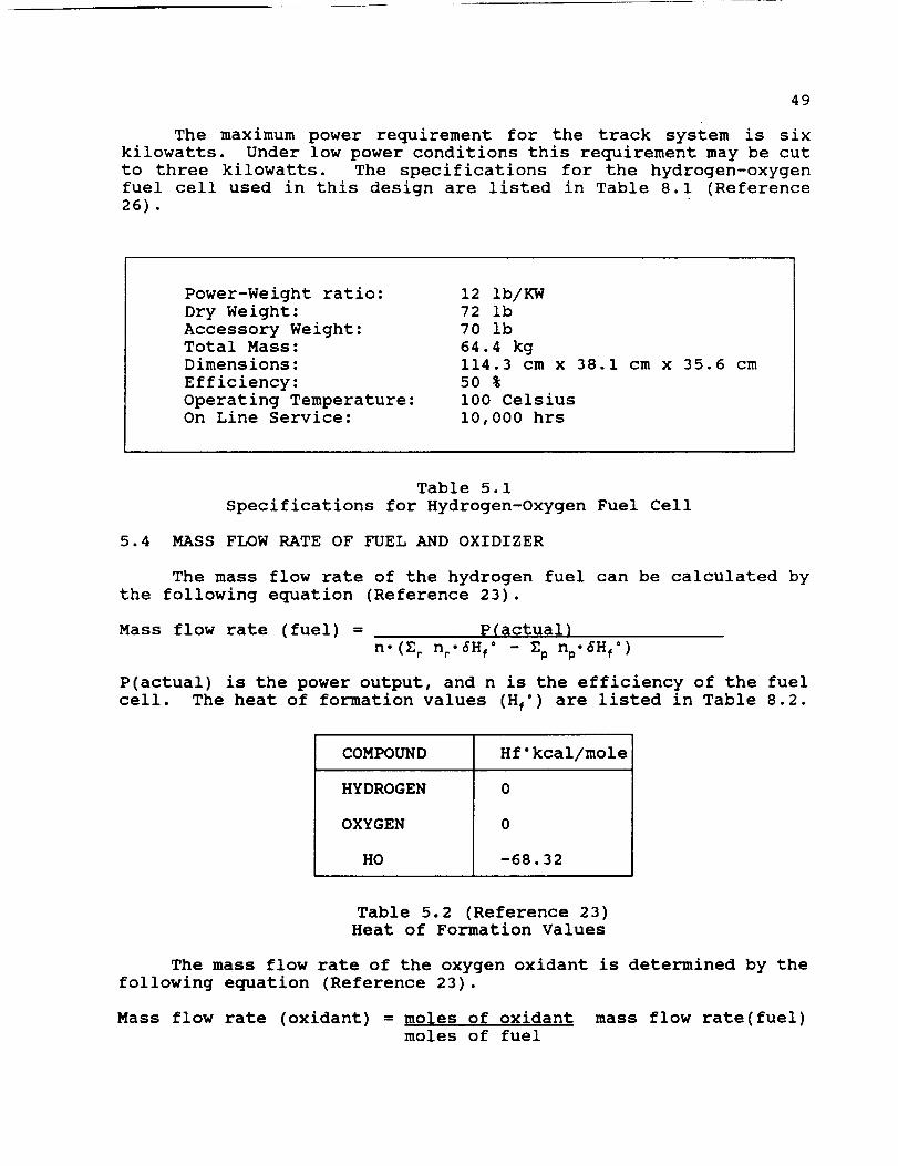
49
The maximum power requirement for the track system is sixkilowatts. Under low power conditions this requirement may be cut
to three kilowatts. The specifications for the hydrogen-oxygen
fuel cell used in this design are listed in Table 8.1 (Reference
26) .
Power-Weight ratio:
Dry Weight:
Accessory Weight:
Total Mass:
Dimensions:
Efficiency:
Operating Temperature:On Line Service:
12 Ib/KW
72 ib
70 ib
64.4 kg114.3 cm x 38.1 cm x 35.6 cm
5O %
I00 Celsius
i0,000 hrs
Table 5.1
Specifications for Hydrogen-Oxygen Fuel Cell
5.4 MASS FLOW RATE OF FUEL AND OXIDIZER
The mass flow rate of the hydrogen fuel can be calculated by
the following equation (Reference 23).
Mass flow rate (fuel) = _(actual)
n.(Z r nr.6Hf ° - Zp np.6Hf °)
P(actual) is the power output, and n is the efficiency of the fuel
cell. The heat of formation values (Hf °) are listed in Table 8.2.
COMPOUND Hf°kcal/mole
HYDROGEN
OXYGEN
HO
0
0
-68.32
Table 5.2 (Reference 23)
Heat of Formation Values
The mass flow rate of the oxygen oxidant is determined by the
following equation (Reference 23).
Mass flow rate (oxidant) = moles of oxidant mass flow rate(fuel)
moles of fuel

5O
The mass flow rate for both hydrogen and oxygen is listed inTable 5.3.
OperatingConditions
Mass Flow Rate
of Hydrogen
Mass Flow Rate
of Oxygen
Maximum
Normal
0.304 kg/hr
0.152 kg/hr
2. 416 kg/hr
1.207 kg/hr
Table 5.3 (Reference 23)
Mass Flow Rate for Hydrogen and Oxygen
5.5 ELECTRODES
There are several different types of materials that can be
used for construction of the electrodes in the hydrogen-oxygen fuel
cell. The type of electrode used for this design is the Raney
electrode. The Raney metals are metals in very divided, highly
active form. They are prepared by mixing the active metal with an
inactive metal, usually aluminum. This mixture is then treated
with strong alkali which dissolves out the aluminum, leaving the
highly developed surface structure desired for the porous
electrodes (Reference 27).
The hydrogen electrode will be made from Raney nickel, by
preparing the electrode structure from a sintered mixture of Raney
alloy (mass fraction 60 per cent AI, 33.6 per cent Ni and 0.4
percent Cr) and ordinary nickel. Most of the aluminum is then
removed with a potassium hydroxide solution (Reference 28).
This material was selected since it is relatively inexpensive,
has a high mechanical strength, and is a highly active non-noble
metal catalyst for hydrogen electrodes in the alkaline fuel cell.
By doping the Raney nickel with chromium the catalytic activity is
enhanced (Reference 28).
A similar kind of electrode can be made for the oxygen side
of the fuel cell. In this case the mixture is made of ordinary
nickel and Raney silver but the surface must be prepared in a
slightly different way because of metallurgical problems. This
material is a very good oxygen catalyst (Reference 27).
5.6 HEAT AND MASS TRANSFER
The heat and water by-products of the electrochemical reaction
in the hydrogen-oxygen fuel cell must be removed. This must be
done to avoid exceeding the maximum critical temperature of the
cell and to prevent an excessive increase in electrolyte volume and
decrease in electrolyte concentration, any one of which could cause
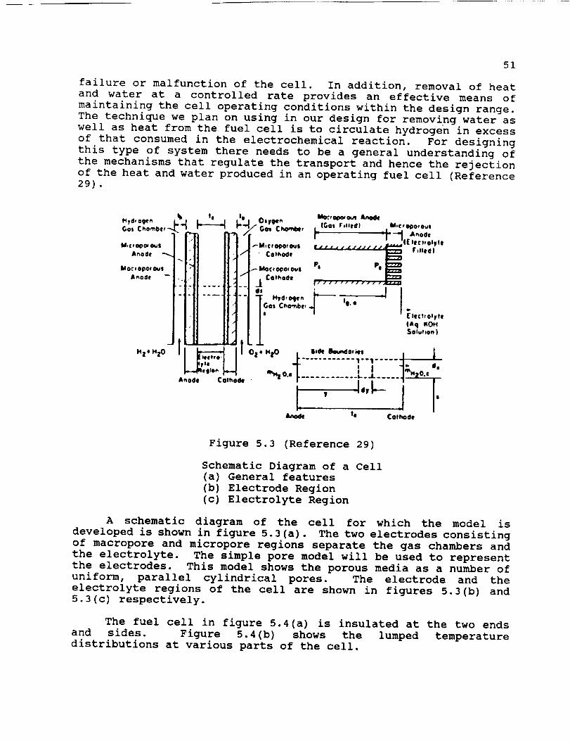
51
failure or malfunction of the cell. In addition, removal of heatand water at a controlled rate provides an effective means ofmaintaining the cell operating conditions within the design range.The technique we plan on using in our design for removing water aswell as heat from the fuel cell is to circulate hydrogen in excessof that consumed in the electrochemical reaction. For designingthis type of system there needs to be a general understanding ofthe mechanisms that regulate the transport and hence the rejectionof the heat and water produced in an operating fuel cell (Reference29) .
Gol Cho,-be, "-4
M,C _O_¢w Ou|
At, ode -_.
MO_ f OI)Of 0_|Anode --
M21 HZO
.__ _*1 O.y94t. I_:, ooe. cxar--I/" Gcn Cho-_, L IGoI F,Iled) M*c,l_o,oum_ [ --_-_ &noDe
,- i : --¢[ lec.olVteP Mi¢ _ IH)O*Oulb lJp,,4/_i_l_ . .. •
• - _/ ' CothOde _ rtlleQI
- ' MO¢ qO_Or _|" / _- Cotl_o4e
•" ; _ i-, ..........
1" Hyd, IMle. I- I -_ |
i IGos ChO.'hbe, _,_ "" I"J_ [lec_,oh, lei IAq _OH
• / l _oluho.)
I lto,,.o ...._o. , A-,.,,.. i] .A.o4e Cotho_ • _ 0., .................
Anod_ te Colhode
Figure 5.3 (Reference 29)
Schematic Diagram of a Cell
(a) General features
(b) Electrode Region
(c) Electrolyte Region
A schematic diagram of the cell for which the model is
developed is shown in figure 5.3(a). The two electrodes consisting
of macropore and micropore regions separate the gas chambers and
the electrolyte. The simple pore model will be used to represent
the electrodes. This model shows the porous media as a number of
uniform, parallel cylindrical pores. The electrode and the
electrolyte regions of the cell are shown in figures 5.3(b) and
5.3(c) respectively.
The fuel cell in figure 5.4(a) is insulated at the two ends
and sides. Figure 5.4(b) shows the lumped temperature
distributions at various parts of the cell.
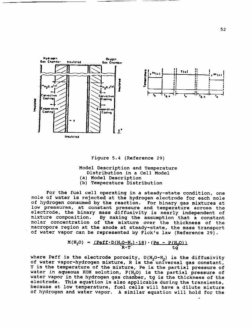
52
InlulO led
i!JlIII
T(II OoInIiio
II , ,II : III l
_I[_ i dIe '- Ii ' ¢ to
Figure 5.4 (Reference 29)
Model Description and TemperatureDistribution in a Cell Model
(a) Model Description
(b) Temperature Distribution
For the fuel cell operating in a steady-state condition, one
mole of water is rejected at the hydrogen electrode for each mole
of hydrogen consumed by the reaction. For binary gas mixtures at
low pressures, at constant pressure and temperature across the
electrode, the binary mass diffusivity is nearly independent of
mixture composition. By making the assumption that a constant
molar concentration of the mixture over the thickness of the
macropore region at the anode at steady-state, the mass transport
of water vapor can be represented by Fick's law (Reference 29).
M(HzO ) = (pef_.D(HzO-Hz ._). (pe - p(HzO})R.T tg
where Peff is the electrode porosity, D(HzO-H 2) is the diffusivity
of water vapor-hydrogen mixture, R is the unfversal gas constant,
T is the temperature of the mixture, Pe is the partial pressure of
water in aqueous KOH solution, P(HzO) is the partial pressure of
water vapor in the hydrogen gas chamber, tg is the thickness of the
electrode. This equation is also applicable during the transients,
because at low temperature, fuel cells will have a dilute mixture
of hydrogen and water vapor. A similar equation will hold for the

53
evaporation of water vapor through the cathode (Reference 29).
Under actual transient operating conditions of the cell, the
mass of the water in the electrolyte will change and the mass of
the KOH will stay constant. This water gain and loss of the
electrolyte will result in a change in the electrolyte and volume.
Changes in the volume could be in the x direction, y direction or
both. For simplicity, we will consider the change in the
electrolyte in the y direction to develop the mass transfer
equations for this case. The mass balance equation for KOH becomes
(Reference 29):
where
6D(KOH) = D(KOH) 6'D(KOH) -
6t 6y'
6 (D (KOH) .V)
6y
p(KOH) = p(OH') + p(K ÷) and D(KOH) = 2 D(K ÷) D(OH')D(K ) + D(OH')
p(KOH) is the density of the potassium hydroxide. D(KOH) is the
binary diffusivity of the electrolyte, V is the volume average
velocity and, D(OH') and D(K ÷) are the diffusivities of OH" and K ÷
ions in the electrolyte (Reference 29).
The passage of two moles of electrons through the cell results
in using two moles of OH" and producing two moles of H20 at the
anode, and producing two moles of OH" and using one mole of H20 at
the cathode. If (i) amperes per unit electrode area per second is
drawn from the fuel cell, the volume average velocity per unit area
for the anode and cathode may be different. The variation between
the two velocities per unit area would lead to an electrolyte
volume increase. In this model the volume between the
electrolyte is kept constant in both the x and y directions
(Reference 29).
The model mass balance equation for KOH is (Reference 29)
6D(KOH) = D(KOH) 6'p(KOH) - V-6D(KOH)
6t 6y' 6y
From this equation the H20 density distribution can be found bythe use of conservation of volume. In the real case the mass of
the KOH should stay constant (Reference 29).
The model proposed in this study, unlike, the actual case,
assumes uniform porosity and complete wetproofing of the electrode
structures. The resulting equations to be solved form a complex
matrix and require a substantial program for their solution on the
computer. The model from this research shows the actual fuel cell
in a qualitative and quantitative manner, such that it can be used
in analyzing fuel cell performance and response to changes in
operating conditions (Reference 29).
54
If the current is turned off or the cell is operated at a muchlower current density than it is designed for, the condensation orevaporation heat effects would involve primarily that forconcentration of the electrolyte; therefore, the differential heatof vaporization of the solvent of the electrolyte should be usedfor these transients instead of heat of vaporization of pure water(Reference 29).
From the mathematical model transients, it is shown that achange in the operation conditions might cause an increase ordecrease in the electrolyte volume, until the electrolyteconcentration readjusts itself. During this process the electrodeshould, for a certain operating range, withstand the danger offailure. But for higher transients the electrodes might deform,dry out or become flooded, resulting in a failure of the fuel cell(Reference 29).
The model and resultant equations presented in this work havebeen shown to effectively represent transient responsecharacteristics of the hydrogen-oxygen fuel cell we have chosenfor our design. These equations can be used to parametricallyanalyze the hydrogen-oxygen fuel cell response to alterations inoperating conditions (Reference 29).
5.7 CONCLUSION
The alkaline hydrogen-oxygen fuel cell appears to be the bestoption for the design of the power system used by the LCUV. Theadvantages are:
- It is small enough to be mounted within the LCUV.- It is light in weight.- It operates in an airless environment and is reliable for
long periods of time.- It is solar independent.
The drawback to this system involves the amount of heat that mustbe dissipated by a radiator. This problem will be addressed inthe thermal control section of the report.
One question we encountered when designing the power systeminvolved how the hydrogen and oxygen tanks were going to bereplaced. This posed a problem since during the first stage ofthe mission the space station will be unmanned. The solution tothis problem involves the use of robotics to perform the task ofremoving and replacing the tanks when necessary.
The second question we had to address was what to do with theby-product water produced by the cell reaction. The solution tothis problem involves collecting the water in tanks. Since wateris a valuable commodity on the moon, we propose to store it forfuture use by the inhabitants on the lunar base.
55
6.0 ELECTRIC MOTOR DRIVE SYSTEM
Since electric fuel cells are proposed to be used to power
the LCUV, electric motors will be employed to drive the vehicle.
Several design problems are encountered in the Lunar environment.
The lunar surface is covered by what is referred to as lunar dust.
This poses a serious threat to the mechanical components of the
motor or any other mechanisms exposed to the environment of the
Moon (Reference 30). Another negative aspect of the environment
of the Moon is that atmosphere is non-existent. The problem
associated with this is that heat dissipation is made difficult
since heat can not be convected away from surfaces. Better methods
must be developed to conduct and radiate generated heat away from
the motor. One more negative characteristic of the Moon is that
its magnetic field which is much smaller than that of the earth is
not capable of shielding the surface from the dangerous effects of
solar flares (Reference 30). This also proves to be a design
problem to be addressed since the electric motor will be partially
exposed to the environment. Electric motors themselves have many
options associated with them: DC or AC, brushed or brushless, and
direct drive or gear reduction. Each option must be analyzed to
find which option is the most feasible for use on the LCUV.
6.1 ELECTRIC MOTOR DESIGN
In the beginning of this report the environmental problemsassociated with the Moon's surface that an electric motor will have
to contend with will be discussed and the requirements of power,
torque, and angular velocity to drive the tracks of the Lunar
Construction Utility Vehicle (LCUV) in the worst case scenario will
be presented. Methods will be developed by which certain problems
can be avoided. Finally, an electric motor that meets the adjusted
requirements will be specified.
6.1.1 ASSUMPTIONS AND DESIGN CONSTRAINTS
The largest influence in determining a motor for use in
driving the LCUV is the environment of the Moon. There are many
constraints associated with the problems affiliated with running
a motor under the conditions presented by the Moon's environment.
The other limiting factors are defined by the worst case scenario.
The maximum requirements for torque and power to drive the tracksof the LCUV will be determined for this case.
Environmental Design Constraints:
D
Temperature ranging from -171°C to III°C.
Damaging effect of lunar dust.
Lack of atmosphere presents problem in convective
heat dissipation from the motor.Effects associated with solar flares and radiation.
Gravitational force is 1/6 that of the Earth's.
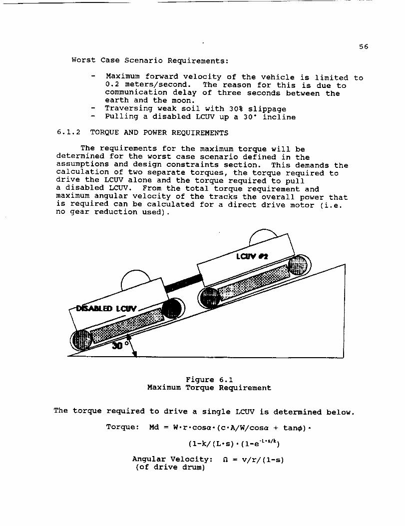
56
Worst Case Scenario Requirements:
- Maximum forward velocity of the vehicle is limited to
0.2 meters/second. The reason for this is due to
communication delay of three seconds between the
earth and the moon.
- Traversing weak soil with 30% slippage
- Pulling a disabled LCUV up a 30" incline
6.1.2 TORQUE AND POWER REQUIREMENTS
The requirements for the maximum torque will be
determined for the worst case scenario defined in the
assumptions and design constraints section. This demands the
calculation of two separate torques, the torque required to
drive the LCUV alone and the torque required to pull
a disabled LCUV. From the total torque requirement and
maximum angular velocity of the tracks the overall power that
is required can be calculated for a direct drive motor (i.e.
no gear reduction used).
Figure 6.1
Maximum Torque Requirement
The torque required to drive a single LCUV is determined below.
Torque: Md = W'r.cosu.(c.A/W/cosu + tan_).
(l-k/(L.s).(l-e "L''/k)
Angular Velocity: N = v/r/(l-s)
(of drive drum)
57
Variables:
MdWr
Lk
sPcPtvn
= Total Torque per track, (in.lbf.)= Total weight of the vehicle per track, (ibf.)= Radius of the drive wheel, (in.)= Angle of incline= Total contact length per track, (in.)= Soil Constant
= Internal friction constant
= Percent slippage
= Average track pressure= Soil cohesion constant
= Total Power required per track,
= Maximum allowable forward velocity,
= Angular velocity, (RPM)
(HP)
(in./sec.)
Results: Md = 4,127 N.m, n = 35 RPM
The torque required to pull a disabled LCUV is given by:
Torque: Mp = W.r.(p.cos_ + sin_)
Angular velocity:
(of drive drum)
n = v/r/(l-s)
Results: Mp = 2,646 N.m
In this analysis the total torque required neglects the sliding
friction of the disabled LCUV. From the above equations and given
the worst case assumptions, the total torque required wasdetermined to be:
M = 6,773 N.m
6.1.3 AC vs DC MOTORS
Motor efficiency is the main factor involved in determining
what type of motor (AC or DC) that is the most feasible for use in
driving the LCUV's tracks. Power losses are to be kept minimal.
The power source for the electric motor is a hydrogen-oxygen fuel
cell supplying a DC current. In order to operate an AC motor an
invertor would have to be employed to convert the DC supply current
into an AC current (Reference 31). When using an invertor there
will be some added power loss. Since any power loss is to be
avoided if possible, the DC motor proves to be more efficient than
an AC motor system, and consequently it will be used on the LCUV.

58
6.1.4 CONVENTIONALVS. BRUSHLESSMOTORS
The conversion of electrical energy to work in a motor istied directly to the commutation of the DC current in the motorwindings (Reference 31). It is here where the difference betweenthe conventional and brushless motor is encountered. As the rotorturns, the magnetic field that is set up by the current through thewindings also rotates. It is because of this that a means ofmaintaining the orientation of the field is needed. Theconventional motor uses brushes which skim along a commutator asseen in figure 6.2. The brushes send a current through a pair ofconductors on the commutator cylinder. The current then flowsthrough each of the winding in a manner which is represented infigure 6.3, thus maintaining a constant orientation of current flowin the windings regardless of rotation. Since this orientation ismaintained a uniform torque in one direction can be maintained.
In the case of the brushless type DC motor the commutation ofcurrent is achieved by using a shaft position encoder inconjunction with a controller (Reference 31). The position of theshaft will be determined by Hall effect sensors. These sensorsdetect polarities and magnitudes of magnetic fields. The signalsgenerated by the sensors are amplified and processed by thecontroller. The controller in turn controls the commutation of thewindings in a similar fashion as the conventional motor exceptwithout the use of brushes (see figure 6.4). Another variation ofthe brushless motor is that the motor windings are located on thestator instead of the rotor, and the permanent magnet is connectedto the rotor (Reference 31).
There are several categories in which conventional andbrushless motors can be compared, for example the ability toproduce torque at high rotational speeds, peak torque, accelerationability, effective life, reliability (maintainability), and dustprotection. All of the mentioned categories must be taken intoconsideration in determining the appropriate type of motor thatwill be used.
Electromechanical commutation at high rotor speeds usingbrushes is limited when compared to the brushless type motor dueto the fact that when using the brush motor there is heat generatedby the frictional contact. In the case of brushless motor'scommutation, it is not dependant on contact so frictional heat willnot limit operation. Thus the brushless type motor can attain
higher rotational speeds and consequently a higher torque rating.
Peak torque is predominately a function current, magnetic
field strength, and number of windings, not of rotational speed.
Both types of motors perform equivalently in this category.
One advantage of having the permanent magnet located on
the rotor as is in the case of the brushless type motor is
that higher torque to inertia ratios can be obtained. Motors with
high torque to inertia ratios have better accelerational abilities
so the brushless type motor is rated better in this category.
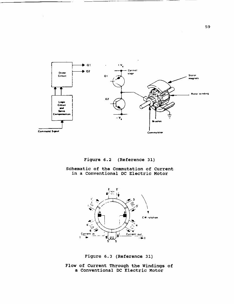
59
I DrJ_f
CIrcu;!
TTL_c
Cm=u-m¢l
Se,n,o
Comqpe_lt*on
Q2
Q1
Q2
,vt,
Control
llt41_P _)titor
ROtOr w*ndlng
-- V|
C_mo|JPt_
Figure 6.2 (Reference 31)
Schematic of the Commutation of Current
in a Conventional DC Electric Motor
Z 2
6___4 .C W rotohon
5' 5
Figure 6.3 (Reference 31)
Flow of Current Through the Windings of
a Conventional DC Electric Motor

60
Dr*vet
¢ln:u*!
* V t
Power
Suppty
- Vs
Se_,
Lq*c Power
*V s
±
J
.
Rotor
Figure 6.4 (Reference 31)
Schematic of the Commutation of Current
in a Brushless DC Electric Motor
Since the brushes on the conventional DC motor are exposed to
friction, as explained previously, they are prone to being replaced
when worn or damaged during operation. This introduces
disadvantages associated with brush type motors. The possibility
of the need for manual maintenance is present and a permanently
sealed casing can not be used. The brush type motor is virtually
maintenance free and can be constructed with a permanently sealed
casing which will prevent contaminants from entering.
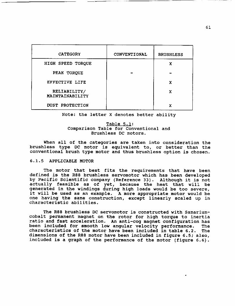
61
CATEGORY
HIGH SPEED TORQUE
PEAK TORQUE
EFFECTIVE LIFE
RELIABILITY/MAINTAINABILITY
DUST PROTECTION
CONVENTIONAL BRUSHLESS
X
m
X
X
X
Note: the letter X denotes better ability
Table 5.1:
Comparison Table for Conventional and
Brushless DC motors.
When all of the categories are taken into consideration the
brushless type DC motor is equivalent to, or better than the
conventional brush type motor and thus brushless option is chosen.
6.1.5 APPLICABLE MOTOR
The motor that best fits the requirements that have been
defined is the R88 brushless servomotor which has been developed
by Pacific Scientific company (Reference 33). Although it is not
actually feasible as of yet, because the heat that will be
generated in the windings during high loads would be too severe,
it will be used as an example. A more appropriate motor would be
one having the same construction, except linearly scaled up incharacteristic abilities.
The R88 brushless DC servomotor is constructed with Samarium-
cobalt permanent magnet on the rotor for high torque to inertia
ratio and fast acceleration. An anti-cog magnet configuration has
been included for smooth low angular velocity performance. Thecharacteristics of the motor have been included in table 6.2. The
dimensions of the R88 motor have been included in figure 6.5; also,
included is a graph of the performance of the motor (figure 6.6).

62
_V_W
L _-_ Wr |_IIU Li
ORIGINAL PAGE IS
OF PO_ OUALr_
Mg_
m
. no= | ,o.mw, I t os==j ]m= I '""" I (..m=_ ]
INmIO I.'p _ imt_ ti_
ImB L im_u i_ry im
Figure 6.5 (Reference 33)Dimensions of the R88 Series Motor
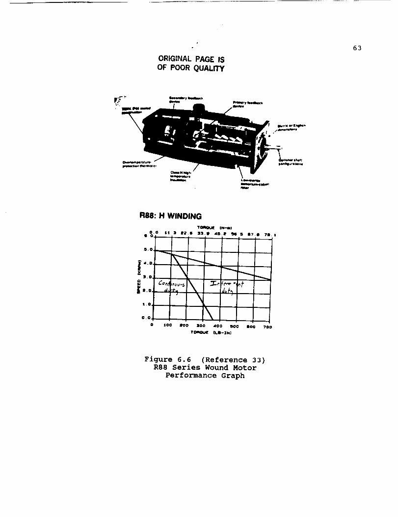
ORIG|NAL PAGE IS
OF POOR QUALITY
63
R88: H WINDING
_roqmlq_ IN-n!
0.0 I1.1 IPI,6 I}.B di_,! aJO,B 17.1 71.I1,0
5.0
4.0
3.0
CoIIJ
j_8.0
t.O
• /
o.o \0 lO0 100 200 dO0 SOG
TOAGU[ I1.11- |NI
II00 ?00
Figure 6.6 (Reference 33)R88 Series Wound Motor
Performance Graph
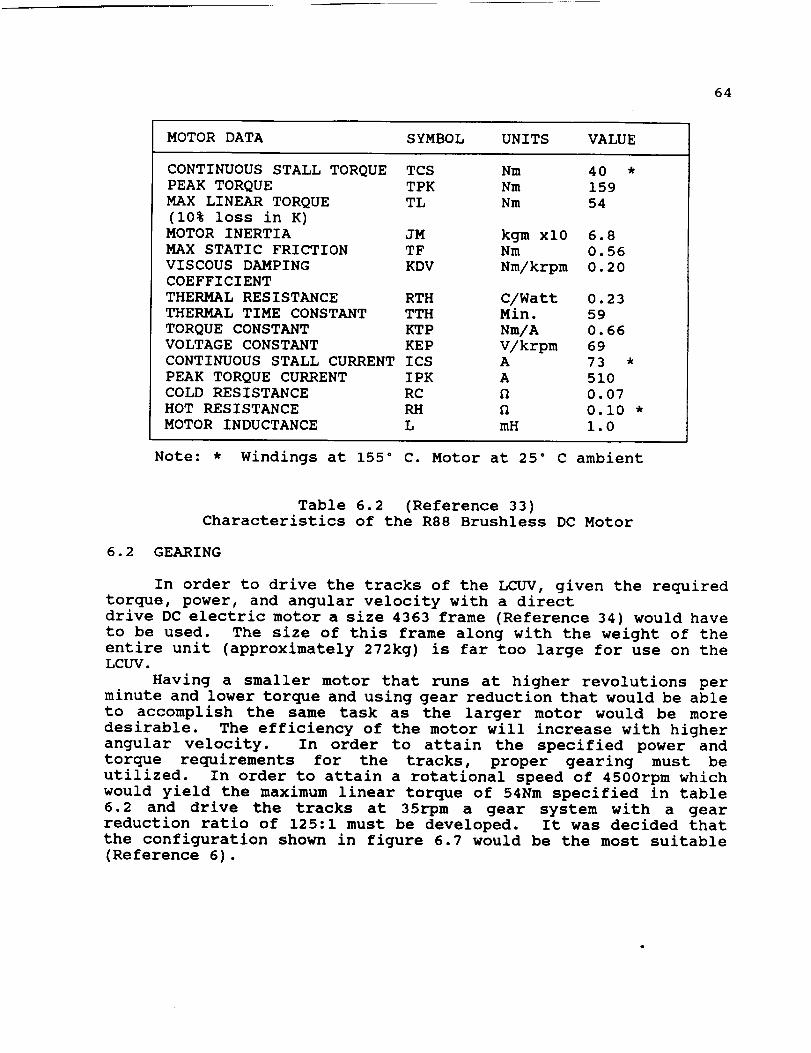
64
MOTOR DATA SYMBOL UNITS VALUE
CONTINUOUS STALL TORQUE TCS
PEAK TORQUE TPK
MAX LINEAR TORQUE TL
(10% loss in K)
MOTOR INERTIA JM
MAX STATIC FRICTION TF
VISCOUS DAMPING KDV
COEFFICIENT
THERMAL RESISTANCE RTH
THERMAL TIME CONSTANT TTH
TORQUE CONSTANT KTP
VOLTAGE CONSTANT KEP
CONTINUOUS STALL CURRENT ICS
PEAK TORQUE CURRENT IPK
COLD RESISTANCE RC
HOT RESISTANCE RH
MOTOR INDUCTANCE L
Nm 40 *
Nm 159
Nm 54
kgm xl0 6.8
Nm 0.56
Nm/krpm 0.20
C/Watt 0.23
Min. 59
Nm/A 0.66
V/krpm 69
A 73 *
A 510
fl 0.07
fl 0.i0 *
mH 1.0
Note: * Windings at 155 ° C. Motor at 25 ° C ambient
Table 6.2 (Reference 33)
Characteristics of the R88 Brushless DC Motor
6.2 GEARING
In order to drive the tracks of the LCUV, given the required
torque, power, and angular velocity with a direct
drive DC electric motor a size 4363 frame (Reference 34) would have
to be used. The size of this frame along with the weight of the
entire unit (approximately 272kg) is far too large for use on theLCUV.
Having a smaller motor that runs at higher revolutions per
minute and lower torque and using gear reduction that would be able
to accomplish the same task as the larger motor would be more
desirable. The efficiency of the motor will increase with higher
angular velocity. In order to attain the specified power and
torque requirements for the tracks, proper gearing must be
utilized. In order to attain a rotational speed of 4500rpm which
would yield the maximum linear torque of 54Nm specified in table
6.2 and drive the tracks at 35rpm a gear system with a gear
reduction ratio of 125:1 must be developed. It was decided that
the configuration shown in figure 6.7 would be the most suitable
(Reference 6).

65
|
iiiiiiiiiiiiiiiiiiiiiiiiiiiiiiiiiiii!iiii!iiiiiiiiiii!i!!!iiiiiiiii!i!ii°
D _)_'_ Dh v_'_
SchematicFigure 6.7
of the Gear Reduction Unit
125:1 Reduction

66
6.3 THE LUNAR DUST PROBLEM
The main aspect of the lunar dust that makes it a design issueis its abrasive nature. If the motor is not properly protected,the dust will substantially reduce the motors useful life(Reference 30). In order to avoid this, the motor's casing mustcompletely enclose the motor to protect it, leaving only the shaftand front face of the motor open to the effects of the dust. Thecasing of the R88 model brushless DC motor is TENV sealed alongwith the shaft (see figure 6.5). An additional method which willbe used to alleviate the effect of lunar dust on the shaft andfront face is a dust cover made of flexible material. The materialmust be able to withstand the high operating temperatures of themotor and not in any way hinder the shaft from delivering therequired torque. In the Environmental Control section of this
report a dust cover made of beta cloth and teflon fiber is
discussed in depth.
6.4 THERMAL DISSIPATION PROBLEM
The difficulties introduced by the absence of atmosphere on
thermal dissipation of heat must be compensated for by introduction
of methods to enhance heat dissipation by conduction and radiation
(Reference 30). The method which has been developed to perform thetask of heat removal from the motor is a radiator unit. This unit
will be responsible for the heat removal needs of the entire
vehicle. The heat that is generated by the motor is conducted to
tubes that are wrapped around the motor and which circulate
ethylene glycol. After the heat has been absorbed by the working
fluid, it is carried away to the radiator which radiates the heat
to the surroundings. The radiator is discussed in more detail in
the Thermal Control section 7.1 of this report.
6.5 SOLAR RADIATION AND FLARE PROTECTION
The major concerns, as far as protection of the electric motor
under the effects of the sun, are thermal fatigue of
the materials when subjected to the frequent sharp changes in
temperature and the problems affiliated with solar flares
(Reference 30). As mentioned previously, the lack of atmosphere
in addition to the weak magnetic field of the moon, provides little
shielding from the radiational effects of the sun. The electric
motor, like other external components, must be protected from these
effects. A majority of the detrimental effects of the sun will be
shielded by the drive drum and tracks. This in addition to the
dust protection cover should be adequate in shielding the motorfrom unwanted radiation.
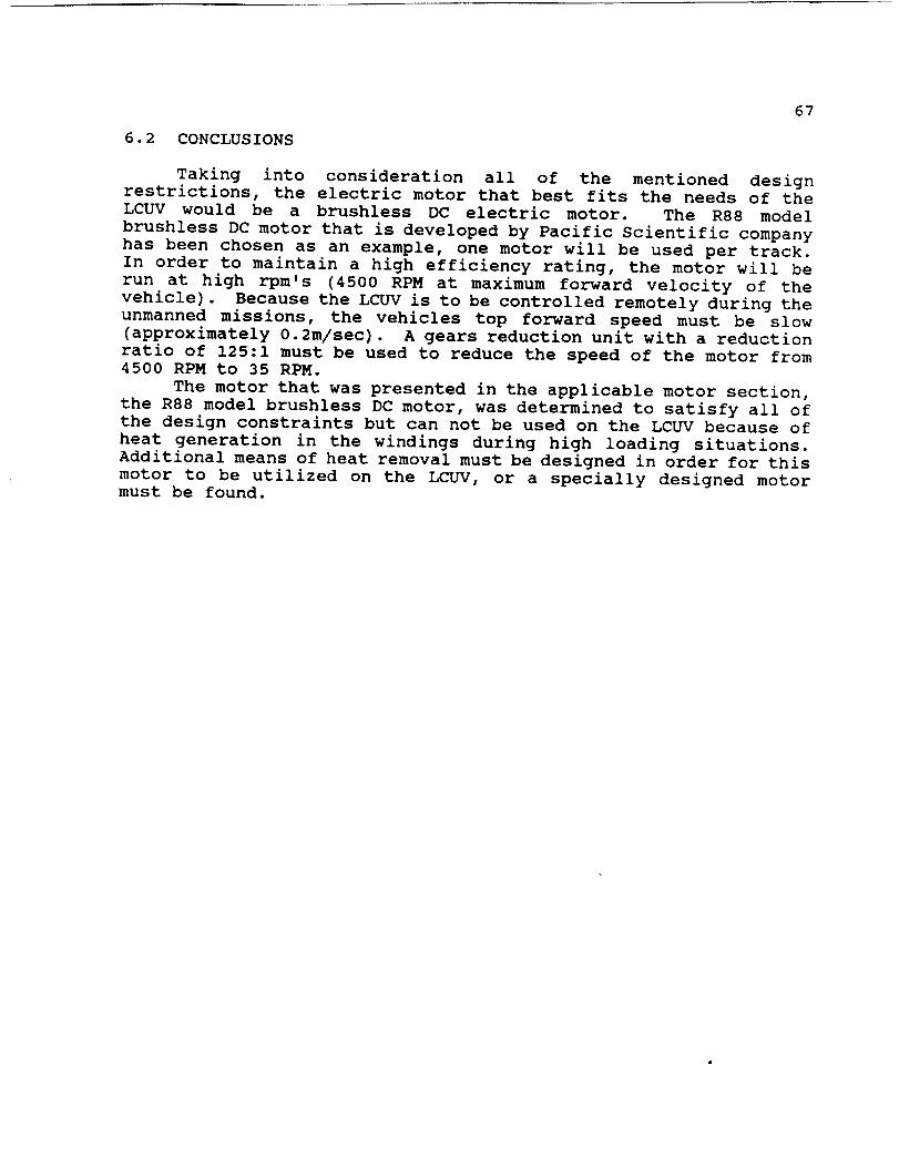
67
6.2 CONCLUSIONS
Taking into consideration all of the mentioned designrestrictions, the electric motor that best fits the needs of theLCUV would be a brushless DC electric motor. The R88 modelbrushless DC motor that is developed by Pacific Scientific companyhas been chosen as an example, one motor will be used per track.In order to maintain a high efficiency rating, the motor will berun at high rpm's (4500 RPM at maximum forward velocity of thevehicle). Because the LCUV is to be controlled remotely during theunmanned missions, the vehicles top forward speed must be slow(approximately 0.2m/sec). A gears reduction unit with a reductionratio of 125:1 must be used to reduce the speed of the motor from4500 RPM to 35 RPM.
The motor that was presented in the applicable motor section,the R88 model brushless DC motor, was determined to satisfy all ofthe design constraints but can not be used on the LCUV because ofheat generation in the windings during high loading situations.Additional means of heat removal must be designed in order for thismotor to be utilized on the LCUV, or a specially designed motormust be found.
68
7.0 THERMAL CONTROL
Heat rejection on the lunar surface can only be accomplished
by radiant heat transfer. This report provides a method for
designing such a radiator. The calculations performed concentrate
on the design of a radiator system for the Lunar Construction
Utility Vehicle; however, the content provided can be used for
other space applications.
7.1 RADIATOR DESIGN
Heat rejection on the lunar surface can only be accomplished
by radiant heat transfer. The size of this radiator is determined
by the amount of heat that must be rejected, temperature of the
radiator surface, and the effective sink temperature. The radiator
temperature is influenced by the thermodynamic cycle efficiency,
pumping fluid characteristics, and the allowable material
temperatures. The effective sink temperature is determined by the
orientation of the radiator surface with respect to the sun and
surface of the moon, as well as daytime and nighttime conditions
and radiator location. The efficiency of the lunar radiator is
improved by lower sink temperatures (Reference 35).
The radiator used in this design will be oriented
perpendicular to the lunar surface. This type of orientation is
advantageous as compared to a horizontal design since the radiator
can have two active sides. By designing a radiator with two active
sides, the overall dimensions will be significantly reduced
(Reference 35).
The radiator material chosen for this design consists of the
aluminum alloy 6061-T6 that will be coated with a zinc oxide
pigment. This particular aluminum alloy was chosen since it meets
the design criteria for lunar application (Reference 37). The
coating selected was found to have a low absorptance-emittance
ratio which is required when designing a radiator. The zinc oxide
pigment is also stable under the influence of solar ultraviolet and
penetrating radiation components of the space environment. In
general, both of these effects will tend to raise the absorptance
value (Reference 35).
Ethylene glycol will be used as the cooling fluid for the
various components on the LCUV. These components include the
hydrogen-oxygen fuel cell, two DC motors, and the on-board control
system. The coolant temperature will range from 360 Kelvin (87
Celsius) to 369 Kelvin (96 Celsius). The boiling point for
ethylene glycol is 471 Kelvin (198 Celsius) under one atmosphere
of pressure, therefore, the liquid will be in the subcooled region
(Reference 37).
A computer program was written by our group and has been
included at the end of this report. The intent of this program
was to aid in the design of our radiator system for the LCUV. In
addition, this program can be used for other space applications
using different parameters (Reference 35).
69
7.1.1 HEAT REJECTION CALCULATIONS
The first phase of the design process involves determiningthe rate of heat rejection required by the radiator. In thisdesign heat must be removed from the hydrogen-oxygen fuel cell, DCmotors, and the on-board control system. The rate of heatrejection required by this system was calculated for each
individual component. The results are listed in Table 7.1.
Component
DC Motors
Controls
Fuel Cell
Heat Dissipation
for Normal OperatingConditions
3 KW
negligible3 KW
Heat Dissipation
for Maximum OperatingConditions
6 KW
negligible
6 KW
Table 7.1
Heat Dissipation Requirements
Once the rate of heat rejection has been calculated, the massflow rate will need to be determined. For these calculations the
mass flow rate of the cooling fluid through a 2.54 cm diameter pipe
is defined to be 0.54 kg/second. This mass flow rate was chosen
in order that a turbulent flow would be produced. The reason
behind this type of flow pattern will be discussed in the nextsection.
The temperature of the cooling fluid at the radiator outlet
was chosen to be 360 Kelvin (87 Celsius). By using this
temperature the specific heat of the cooling fluid can be
determined. Since the specific heat of the cooling fluid varies
slightly with temperature, only a small error is introduced into
the calculations.
The temperature of the cooling fluid at the radiator inlet
can be found by rearranging the following equation (Reference 35).
Q = w.cp (T_i - T_o )
The relation between the temperatures of the cooling fluid
and the radiator wall temperatures can be obtained by taking a heat
balance at any location on the radiator. The heat balance is made
between the radiative and convective heat flow for a unit area.
The temperature drop through the wall is assumed to be small;
therefore, the outside wall temperature is approximately equal to
the inside wall temperature. Equating the convective and radiative
heat flow results in the following expression shown below
(Reference 35). I4 &
Hr. (T_ - T_) = a._. (Tw - Ts)
Rearranging this equation gives the general expression
radiator wall temperature (Reference 35).
4 4
T_ = Tf - a.6. (T W - T,)/Hr
The inlet radiator wall temperature becomes (Reference 35),
4 4
T_i = Tfi - a._.(Twi - Ts)/Hr
The outlet radiator wall temperature becomes (Reference 35),
70
for the
4 4
T,o = Tf0 - a._. (Two - Ts)/Hr
In these equations for calculating the radiator wall
temperatures the convective heat transfer coefficient can be
estimated (Reference 35). The method for determining the
convective heat transfer coefficient will be demonstrated in the
next section. In addition, the effective sink temperature can be
calculated as shown in a subsequent section.
7.1.2 CONVECTIVE HEAT TRANSFER COEFFICIENT
A popular method for computing the local Nusselt number for
fully developed turbulent flow in a smooth circular tube is the
Dittus-Boelter equation. The expression for this equation is as
follows (Reference 38).
Nu = 0.023 Re4/5.Pr"
where n=0.3 for cooling. This equation has been
experimentally for the following range of conditions
38):
confirmed
(Reference
i) 0.7 < Pr < 160
2) Re > i0,000
3) L/D > i0
This equation should be used only for small to moderate differences
in the cooling fluid temperature and radiator wall temperature.
Since the average Nusselt number for the entire tube depends
INote: A list of subscripts and symbols are included in
Appendix B.

71
on the inlet conditions, as well as on the Reynolds and Prandtlnumber, generally applicable equations are not available. However,to a first approximation, the foregoing equation may be used toobtain a reasonable estimate of the average Nusselt number. Whendetermining the average Nusselt number all fluid properties shouldbe evaluated at the arithmetic average of the inlet and outletfluid temperatures (Reference 38).
Once the Nusselt number has been determined, the convectiveheat transfer coefficient can be calculated. The expression forthe convective heat transfer coefficient is (Reference 38)
Hr = (Nu.K)/D
7.1.3 EFFECTIVE SINK TEMPERATURE
Variables that affect the sink temperature (Ts) of a radiatorare lunation, radiator location, and orientation. The radiator issubject to three different sinks: (I) the surface of the moon,which is assumed to be a black body, (2) space, and (3) the sun.For this reason equations must be developed expressing theeffective sink temperature as a function of the three sinkvariables. The heat rejection rate for a .305 by .305 meter (i by1 foot) section of radiator with two active sides can be expressedin terms of radiator orientation, location, and lunation as(Reference 35)
4 4 4q = 2"_'a'Tw,.v - FI"_'a'T m -F2"_'a'T m - IG$'_,'cOSenl
Since FI+F2=I.0, the above equation becomes: (Reference 37) 24 4
q = 2._.a.T_,,v - _.a.Tm - IG ._ .cOSenl
The lunar temperature (Tm) is given in figure 7.1. In ourcalculations we assumed that the LCUV would be operated at 45degrees latitude. In addition, the radiator average walltemperature (Tw,av) for these calculations is the integratedaverage of the temperature of the radiator surfaces. The methodfor determining this will be given in the next section.
2Note: F1 and F2 are the shape factors for the radiator.

70O
_Sunrise
t l Io 3o 6o
72
Figure 7.1 (Reference 35)
Lunar Surface Temperature
The heat rejection rate for a .305 by .305 meter section of
a radiator with one active side can be expressed in terms of
average wall and sink temperature by the following equation
(Reference 37).
4 4
q = O'e'(Tw,,v - T,)
Since our design for the radiator has two active sides, the right
side of this equation must be multiplied by 2.0.
For the radiator with two active sides, the last two equations
can be combined to yield (Reference 35)
4 4
2.e.O.Tw, av- e.o.T.- IG,.u,.cose, l=
4 4
2"•'O'.(Tw,ev - T s).
Solving for the sink temperature results in
Ts
T 4 +m
2L],,4G s • e cos en
2"_ S
73
7. i. 4 RADIATOR WALL TEMPERATURE
When the heat rejection process is one similar to condensing,
the fluid temperature is uniform and nearly constant from inlet to
exit conditions. For this case, the arithmetic average of the
inlet and exit wall temperatures can be used for average radiator
wall temperatures. However, in a radiator, the temperature of the
fluid decreases from inlet to outlet so that an integrated average
should be used for this case. The expression for the radiator
average wall temperature is shown below (Reference 35).
7.1.5 PRIME RADIATOR AREA
The prime radiator area (AR) can now be determined by using
the following equation (Reference 35).
4 4
AR = Q/a._. (Tw,,v - Ts)
The radiator designed for the LCUV will have two active sides.
7.2 CONCLUSION
There will be two radiators used in order to reject heat from
the fuel cell, two motors, and on-board control system. The
primary radiator will be attached to the back of the vehicle behind
the operator's bubble and will accommodate normal operating
conditions during solar night. This radiator will have a prime
area of 7.3 square meters. Since there are two active sides to the
radiator, the overall dimensions will be 1.2 meters long by 3.0
meters high. If conditions become greater than normal for solar
night operation a secondary radiator will be required. This
secondary radiator can be attached to the vehicle by a trailer and
will have a prime area of 15.0 square meters. The overall
dimensions for this radiator will be 2.7 meters long by 2.7 meters
high. The placement of these two radiators was chosen in order
that they would not interfere with the LCUV working parts.
The advantages of this design include:
- This method of design can be used for any type of space
applications.
- This radiator can be used with any type of coolant fluid.
- Radiant heat transfer is the only method to dissipate heaton the lunar surface.
The disadvantages of this design include:
- This radiator is quite large, especially under maximum
power conditions.
- A pump must be designed for circulation of the coolantfluid.
74
8 .0 ENVIRONMENTAL CONTROL
This paper will develop ways to provide environmental control
of important areas of the Lunar Construction and Utility Vehicle.
The purpose of this facet of the design is to develop ways to
provide a manual control area that is protected from dust, debris,
meteoroid showers, and radiation, while still allowing the vehicle
operator to have an unobstructed view of the working area. A
double pane system of glass, made of lithium-aluminumsilicate as
the inner pane and fused-silica as the outer pane, placed over the
cabin area will allow such protection and visibility. This design
also includes a garment to protect movable parts from dust and
debris, including the motors in the wheel well and the motors of
the robotic arm. The cabin area will also be protected. A
combination of Beta Cloth and Teflon TFE, similar to the garment
used in the design of the Skylab Extravehicular Mobility Unit, will
accomplish the desired result.
When dealing with space applications, environmental control
becomes difficult. In this facet of the design, areas such as the
manned control area, which will be referred to as the cabin, and
the joints and openings of movable parts need to be kept free from
dust and debris. Each area has special considerations that need
to be taken into account due to the effects of the lunar
environment. For example, the cabin area needs to be made of a
transparent material that will allow the operator of the LCUV to
have an unobstructed view of the working area. The covering of
the movable parts, which shall be referred to as boots, need to beflexible and durable.
These designs are easily developed on earth. However, the
harsh environment of the moon causes very different effects due to
the large temperature gradients and radiation fluxes. The
temperature and radiation changes have varying effects on all
materials in this environment. An added problem that exist in the
lunar environment is that of micrometeoroid showers. This becomes
especially important if the operator is allowed to work while
partially suited.
8.1 CABIN DESIGN
Although the initial stage of a lunar base buildup will notbe manned, there will be an eventual need for a cabin area where
manual control of the LCUV can take place. This section will
outline some of the basic considerations of the cabin area.
75
8.1.1 ASSUMPTIONS
I) The vehicle will not need transparent material to coverthe cabin area until the manned stages of theSplit-Mission Project (Reference I0).
2) The cabin area will be covered by the same material beingdesigned for the boot when the transparent sphericalcover is not in place.
3) The Skylab Extravehicular Mobility Unit,(Reference 39), ora comparable spacesuit will be worn during operation ofthe vehicle.
The cabin area will be 1.5 meters in diameter. The coveringof this area will be in the shape of a semi-hemispherical shell.This sphere will be made out of a material that will allow thecontroller 360 degree visibility while operating the vehicle frominside the cabin. The sphere can be assembled and disassembled byuse of the robotic arm. The sphere will have three keywicks thatwill allow the bubble to be locked and unlocked by rotation; seeFigure 8.1 for dimensions of the keywicks.
8.1.2 MATERIAL BACKGROUND
There are many types of materials that could be considered
for the design of a transparent sphere. Due to project limitations
on time, only glass materials were investigated.
Some problems when considering the use of glass are the
absorption of X- and gamma radiation. The absorption of these types
of radiation causes the formation of color centers, resulting in
absorption bands with peaks at specific wavelengths (Reference 40).
Most silicate glasses color brown under high energy radiation, I0_5
R or more. Phosphate glasses color purple, but have much narrower
absorption bands. Ultraviolet radiation also produces coloration
in glasses containing pairs of certain elements; e.g. As and Mn,
As and Fe, Sb and Mn, and Sb and Fe; but this is highly dependent
upon the ultraviolet wavelength (Reference 41).
Arutunian and Seppi (Reference 42) subjected transparent
materials to x-ray irradiation to determine how ionizing radiation
affected their optical transmission. The materials used were
aluminate glass, polystyrene, plexiglass, allycarbonate and
polyvinyl acetate. Figures 8.2 and 8.3 (Reference 41) show the
transmission of solar radiation at the surface of the earth as a
function of dosage. Often materials are also commonly used in
infrared transmission including quartz, fused silica, and several
glasses. Penetrating radiation induces in all of these materials
changes similar to those discussed previously (Reference 42).
Figure 8.4 (Reference 43) presents the charges in transmission
efficiencies produced by gamma-irradiation of four different
materials used in space infrared optics.
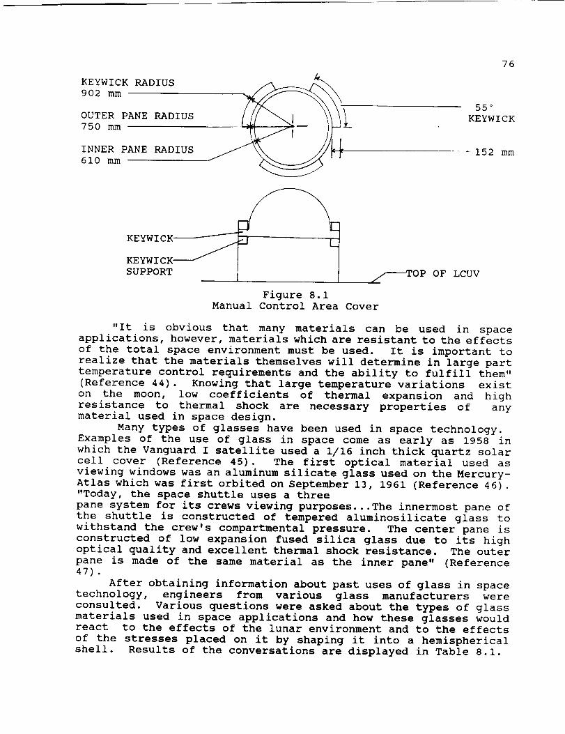
KEYWICKRADIUS902 mm
OUTER PANE RADIUS750 mm
INNER PANE RADIUS610 mm
76
55 °KEYWICK
152 mm
KEYWICK_
KEYWICK---_" I Ii I
Figure 8. i
Manual Control Area Cover
----TOP OF LCUV
"It is obvious that many materials can be used in spaceapplications, however, materials which are resistant to the effects
of the total space environment must be used. It is important to
realize that the materials themselves will determine in large part
temperature control requirements and the ability to fulfill them"
(Reference 44). Knowing that large temperature variations exist
on the moon, low coefficients of thermal expansion and high
resistance to thermal shock are necessary properties of anymaterial used in space design.
Many types of glasses have been used in space technology.
Examples of the use of glass in space come as early as 1958 in
which the Vanguard I satellite used a 1/16 inch thick quartz solar
cell cover (Reference 45). The first optical material used as
viewing windows was an aluminum silicate glass used on the Mercury-
Atlas which was first orbited on September 13, 1961 (Reference 46)."Today, the space shuttle uses a three
pane system for its crews viewing purposes...The innermost pane of
the shuttle is constructed of tempered aluminosilicate glass to
withstand the crew's compartmental pressure. The center pane is
constructed of low expansion fused silica glass due to its highoptical quality and excellent thermal shock resistance. The outer
pane is made of the same material as the inner pane" (Reference47).
After obtaining information about past uses of glass in space
technology, engineers from various glass manufacturers were
consulted. Various questions were asked about the types of glass
materials used in space applications and how these glasses would
react to the effects of the lunar environment and to the effects
of the stresses placed on it by shaping it into a hemispherical
shell. Results of the conversations are displayed in Table 8.1.
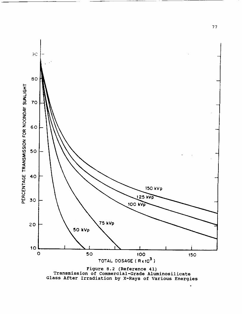
77
90 I
tO0
25
150 kVp
2O
50 kVp
75 kVp
100
I
50 1OO 150
TOTAL DOSAGE ( Rx fO 3 }
Figure 8.2 (Reference 41)Transmission of Commercial-Grade Aluminosilicate
Glass After Irradiation by X-Rays of Various Energies

-'2
CD
q
o0,_ _0
.C,r"(._)Z
0
oRIGINAL PAGE IS
OF p(X)R QUALITY
t
i
',,'IT_ - ",-S ._,__:¢A
0 5O
, [_00 _ 3 200
DAMAGING NEUTRONS (10_8neutrons/cm 2)
'F
78
i;
• ¢
(x)
_5
_o
Z
5
0
J i K iI- I!
ALLI QUARTZ
O 50 400 qSO 200
DAMAGING NEUTRONS ( 1018 neutronslcm 2 )
V
1(x)
Figure 8.3 (Reference 41)Change in Density of Vitreous silica and Quartz on Irradiation in
Nuclear Reactors. The dosage at (x) is estimated at 250 to 400.

oRiGINAL PAGE ISOF POOR QUALITY 79
IOO
90
80
7o
5O
40
30
20NO RADIATION
...............................1.541= t96 R10I.O = I0 = R
I00
90
eO
?0
6O
50
40
30
ZO
10
I [ _ AI_SFNIC TRiSULFI0£
TMICKNESS 3 3ram ---_'-
GAMMA SOURCE: C0"60 _i]DOSE RATE: 1,95 =101 R/hr -- ,:
(o)
GERMANIUM 34.6ohm-cm I ] I I- TMICKNESS 6.3mm
I 1_ GAMMA SOURCE: C0-60
DOSE RATE: I ¢J5 a lOS R/hrNO RADIATION
NOT SHOWN 1.58 • 106 RI.O=1OeR
[ 1
,_ K3_AK Mg Fz
-L-- _L_____
/I GAMMA \---_J- SOURCE : CO-60 ._.Dose i I _--L RATE: 1.95•10 !1 R/.r -- _ __
NO RADIATION _,................ 1.5Sl|O8 R -- _,
..... 1'O = 1OIR k!
(b)
SIUCON(SINGLECRYSTAL ( I I T
J I_L GAMMA SOURCE: C0-60
i DOSE RATE: 1 cJ5 =10 5 R/hr
t. NO EFFECT
f 1! i _,
I i J l ItJ l2 3 4 5 6 7 e g 10 II 12 1:3 14 0 I 2 3 4 5 B 7 8 9 10 11 _2 '3
WAVELENGTH (ju,) WAVELENGTH {pL)
(c) (4)
NO RADIAT;ON1.58 • 10' R
tO = lOeR
[ I p : ,
' ii -,+ 1--
i
Figure 8.4
Effects of high level radiation on transmission efficiency of
four materials presently used for space vehicles.
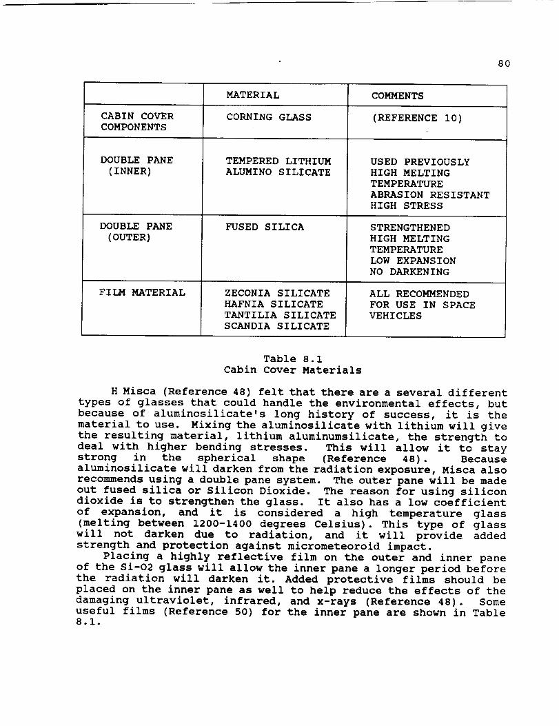
8O
CABIN COVERCOMPONENTS
DOUBLEPANE(INNER)
DOUBLEPANE
(OUTER)
FILM MATERIAL
MATERIAL
CORNING GLASS
TEMPERED LITHIUM
ALUMINO SILICATE
FUSED SILICA
ZECONIA SILICATE
HAFNIA SILICATE
TANTILIA SILICATE
SCANDIA SILICATE
COMMENTS
(REFERENCE i0)
USED PREVIOUSLY
HIGH MELTING
TEMPERATURE
ABRASION RESISTANT
HIGH STRESS
STRENGTHENED
HIGH MELTING
TEMPERATURE
LOW EXPANSION
NO DARKENING
ALL RECOMMENDED
FOR USE IN SPACE
VEHICLES
Table 8.1
Cabin Cover Materials
H Misca (Reference 48) felt that there are a several different
types of glasses that could handle the environmental effects, but
because of aluminosilicate's long history of success, it is the
material to use. Mixing the aluminosilicate with lithium will give
the resulting material, lithium aluminumsilicate, the strength to
deal with higher bending stresses. This will allow it to stay
strong in the spherical shape (Reference 48). Because
aluminosilicate will darken from the radiation exposure, Misca also
recommends using a double pane system. The outer pane will be made
out fused silica or Silicon Dioxide. The reason for using silicon
dioxide is to strengthen the glass. It also has a low coefficient
of expansion, and it is considered a high temperature glass
(melting between 1200-1400 degrees Celsius). This type of glass
will not darken due to radiation, and it will provide added
strength and protection against micrometeoroid impact.
Placing a highly reflective film on the outer and inner pane
of the Si-O2 glass will allow the inner pane a longer period before
the radiation will darken it. Added protective films should be
placed on the inner pane as well to help reduce the effects of the
damaging ultraviolet, infrared, and x-rays (Reference 48). Some
useful films (Reference 50) for the inner pane are shown in Table8.1.

81
8.1.3 DESIGN DECISIONS
A double pane system will be used as shown in Figure 8.1. The
inner pane will be made of 12.7 millimeters thick tempered lithium-
aluminosilicate glass and has a silicate or reflective coating that
will reflect the infrared and ultraviolet rays. This will aid in
both thermal control and the problem of glass darkening. The outer
pane should be 1.59 millimeters thick to help prevent it from
cracking due micrometeoroid impacts. It should be coated with a
high efficiency antireflective coating to improve visible light
transmission. This is similar to that used on the space shuttle's
forward windows (Reference 47).
A summary of the design choices and the primary reasons for thesechoices are outlined in Table 8.2.
The film information that has been obtained is general in
nature. The thicknesses expressed by Meskot (Reference #i0) were
based primarily on the those taken from the space shuttle's pressinformation (Reference 47). There has been a modification of the
inner surface due to the lack of pressurization of the lunar
vehicle. The total weight of the covering was calculated to be 64
kilograms (Reference 50). A summary of the weights of each
component of the glass sphere is shown in Table 8.3.
DECISION
GLASS
SPHERICAL SHAPE
KEYWICK LOCK
DOUBLE PANES
FILM COATED
INNER PANE
REFLECTIVE FILM
OUTER PANE
RATIONALE
UNOBSTRUCTED VISIBILITY
NO BLIND SPOTS
SIMPLE DESIGN
CAN BE PRESSURIZED
HIGH STRENGTH
LONG LIFE
RADIATION RESISTANT
FACILITATES PRESSURIZATION
PROVEN SPACE DESIGN
ADDS STRENGTH
PREVENTS DARKENING
Table 8.2
Cabin Area Design Summary
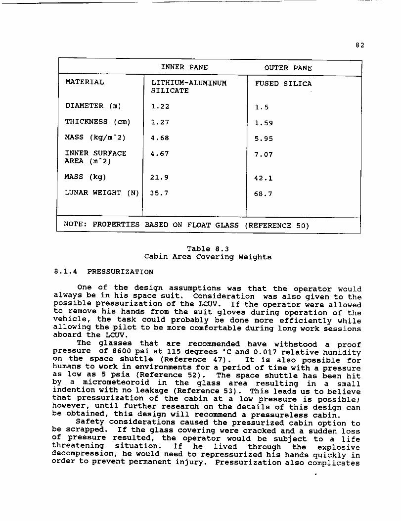
82
INNER PANE OUTER PANE
MATERIAL FUSED SILICA
DIAMETER (m)
THICKNESS (cm)
MASS (kg/mA 2)
INNER SURFACE
AREA (mA2)
MASS (kg)
LUNAR WEIGHT (N)
LITHIUM-ALUMINUM
S ILI CATE
1.22
1.27
4.68
4.67
21.9
35.7
1.5
1.59
5.95
7.07
42.1
68.7
NOTE: PROPERTIES BASED ON FLOAT GLASS (REFERENCE 50)
Table 8.3
Cabin Area Covering Weights
8.1.4 PRESSURIZATION
One of the design assumptions was that the operator would
always be in his space suit. Consideration was also given to the
possible pressurization of the LCUV. If the operator were allowed
to remove his hands from the suit gloves during operation of the
vehicle, the task could probably be done more efficiently while
allowing the pilot to be more comfortable during long work sessionsaboard the LCUV.
The glasses that are recommended have withstood a proof
pressure of 8600 psi at 115 degrees °C and 0.017 relative humidity
on the space shuttle (Reference 47). It is also possible for
humans to work in environments for a period of time with a pressure
as low as 5 psia (Reference 52). The space shuttle has been hit
by a micrometeoroid in the glass area resulting in a small
indention with no leakage (Reference 53). This leads us to believe
that pressurization of the cabin at a low pressure is possible;
however, until further research on the details of this design can
be obtained, this design will recommend a pressureless cabin.
Safety considerations caused the pressurized cabin option to
be scrapped. If the glass covering were cracked and a sudden loss
of pressure resulted, the operator would be subject to a life
threatening situation. If he lived through the explosive
decompression, he would need to repressurized his hands quickly in
order to prevent permanent injury. Pressurization also complicates

83
and adds weight to the design. Since the design goals are to keepthe overall mass as low as possible and to simplify the details,pressurization was ruled out for this initial design of the LCUV.
8.2 DUST COVERINGDESIGN
The coverings that will be used to keep dust and other debrisout of working parts of the LCUV will be referred to as boots. Theproposed coverings will be placed over the wheel wells of thetracks, mechanical arm joints, and the cabin area.
The main problem for this design was finding a material that
was flexible enough to move with the equipment and seal the parts
from dust. The materials that were considered are Dupont Teflon
TFE fiber, and Beta Cloth, made by the Owens-Corning Corporation.
Both Beta Cloth and Teflon fibers have been used in the SkylabExtra Vehicular Mobility Unit. The properties of the two materials
that were used for the spacesuit design are shown in Table 8.4
(Reference 39). Because the extravehicular garment assembly (or
spacesuit) has many of the same general requirement as the boot,the materials used in the EVA suit have been considered in the boot
design.
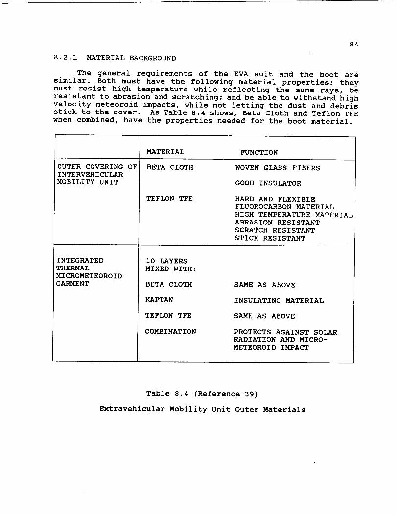
84
8.2.1 MATERIAL BACKGROUND
The general requirements of the EVA suit and the boot aresimilar. Both must have the following material properties: theymust resist high temperature while reflecting the suns rays, beresistant to abrasion and scratching; and be able to withstand highvelocity meteoroid impacts, while not letting the dust and debrisstick to the cover. As Table 8.4 shows, Beta Cloth and Teflon TFE
when combined, have the properties needed for the boot material.
OUTER COVERING OF
INTERVEHICULAR
MOBILITY UNIT
MATERIAL
BETA CLOTH
INTEGRATED
THERMAL
MICROMETEOROID
GARMENT
TEFLON TFE
i0 LAYERS
MIXED WITH:
BETA CLOTH
KAPTAN
TEFLON TFE
COMBINATION
FUNCTION
WOVEN GLASS FIBERS
GOOD INSULATOR
HARD AND FLEXIBLE
FLUOROCARBON MATERIAL
HIGH TEMPERATURE MATERIAL
ABRASION RESISTANT
SCRATCH RESISTANT
STICK RESISTANT
SAME AS ABOVE
INSULATING MATERIAL
SAME AS ABOVE
PROTECTS AGAINST SOLAR
RADIATION AND MICRO-
METEOROID IMPACT
Table 8.4 (Reference 39)
Extravehicular Mobility Unit Outer Materials

85
One of the main problems with this design is the longevity ofthe materials being used. This is also a problem with the EVA suitdesign; the exact useful life span of the spacesuit has not yetbeen determined (Reference 55). To express why the Teflon fiberis being used in the boot design, Table 8.5 shows some generalproperties of the fiber. Teflon fiber is the most chemically-resistant fiber known. Molecules of Teflon fiber are electricallyneutral and have no strong polar forces binding them together, asin the case of nylon or cellulosic fibers. The unique molecularstructure of this Teflon fiber also accounts for the fibersstability at extreme temperature conditions. The fiber softens at
elevated temperatures and becomes less ductile at sub-zero
temperature; however, experience indicates that adequate toughness
and strength are available for uses at temperatures as low as -
268°C and as high as 288°C. The fibers are found to be most
ductile and flexible between 288°C and -268°C. The maximum
temperature Teflon TFE fiber can be exposed for long periods of
time is 288°C, but brief exposures to temperatures as high as 316°C
can be tolerated (Reference 57). Sunlight resistance and radiation
resistance is a necessity to any material used on the lunar
surface. The sunlight and weather resistance of this fiber is
outstanding according to DuPont (Reference 58). Three years
continuous use in Miami, Florida, produced only a 2% loss in yarn
strength (Reference 59). "The effects of high radiation and vacuum
conditions of this fiber are given in by (Figure 8.5)" (Reference
57).
,,, 100
<
<Z
0
r_o
0
I--Z
n,-
5O
0 ..I,
10 J
(10)
EJon
i
104(102)
(in air)
Tensde Strength
lOS 106 10' 10'(10') (10') (lO s) (10 _)
DOS[, in rads (Gy)
Figure 8.5 (Reference 57)Effects of Radiation on Teflon

86
TYPICAL PROPERTIESFOR UNBLEACHEDYARNS OF TEFLON TFE FIBER
YARN DENIER (i GRAMPER 9000 METERS)
STRESS STRAIN PROPERTIES
STRENGTHTESTTENSILE STRENGTH(MPa)BREAKING STRENGTH(N)BREAKING TENACITY (G/DEN)ELONGATIONAT BREAK (%)INITIAL MODULUS(G/DEN)
LOOP TESTTENSILE STRENGTH(MPa)BREAKING STRENGTH(N)ELONGATIONAT BREAK (%)
THERMALPROPERTIES
SHRINKAGEAFTER 30 MIN. (%)IN WATERAT 100°CIN AIR AT 177°C
SPECIFIC HEAT (CAL/G/°C)
THERMALCONDUCTIVITY (W/m_K/cm thk.)
ZERO STRENGTHTEMPERATURE(°C)
GEL TEMPERATURE(°C)
SUBLIMATION RATE (% WT. LOSS/HR)AT 290 °CAT 430 °C
GENERALPROPERTIES
SPECIFIC GRAVITY
MOISTUREREGAIN (%)
FILAMENT DIAMETER (mm)
400 1200
29018.71.6358.3
19724.518
BOTH
2.56.0
0.25
3.8
310
327
0.000021.5
2.1
3597.62.01913
2148.08.5
0.0
0.02
Table 8.5Properties of TFE Fluorocarbon Yarns

87
8.2.3 DESIGN DECISIONS
The final design of the boot cannot yet be detailed. It isknown that the material to be used will be a Beta Cloth and Teflon
TFE mixture interwoven much the same as the outer garment of the
EVA. The part of the design that cannot be finalized deals with
the thickness of the interwoven material. Powell (Reference 54)
explained, "Every specific use of the Teflon TFE fiber needs its
own testing in order to find out the fibers specific reaction dueto a mixture of materials in a certain environment."
8.3 CONCLUSIONS
As shown, trying to provide a safe and clean environment with
the conditions that exist on the moon is very demanding. A double
pane hemispherical shell made of fused-silica on the outside and
lithium-aluminumsilicate on the inside was chosen as the cover of
the manual control area of the LCUV. A fiber mixture of Beta Cloth
and Teflon TFE has been chosen to keep vital areas free from dust,
debris, and meteoroid showers. This material is very flexible and
has been shown to stand up to severe conditions and large
temperature variations. This work is somewhat general in nature.
Once the details of the LCUV begin to emerge, a detailed design of
the boots and coverings can be accomplished.
SP
88
9.0 RADIATION SHIELDIN_
This report explains the radiation hazards present on the
lunar surface. Radiation has two effects on humans, somatic and
genetic. Its chief energy form is that of ionizing matter. A
strategy to shield man from radiation has three steps: (I)
aluminum is used on the hardshell casing of the lunar vehicle, (2)Kapton films meshed with quartz fibers are blanketed in the
interior of the module, (3) a protective coating of aluminum will
then be applied to the exterior of the lunar vehicle. Concluding
remarks will address the feasibility and safety issues.
9.1 RADIATION TYPES
Ionizing radiation is man's greatest concern. "In this
category are solar, galactic, and extragalactic cosmic rays, X rays
and gamma rays from the Sun, solar flare and solar wind particles,
electrons and protons of the Van Allen Belts of trapped radiation,
neutrons, and alpha particles (Reference 60)." Why does radiation
due to the Sun exist on the Moon and not on the Earth? The Earth's
atmosphere and magnetic fields act as a shield, blocking out
harmful radiation rays. The Moon, however, does not have an
atmosphere and therefore has no radiation shielding (Reference 60).
Knowing that radiation now exists on the Moon, what is its chief
source? This question leads us into the discussion of the 'Cosmic
Barrier'. 'Cosmic Barrier', as its name infers, involves cosmic
radiation. Cosmic radiation involves primary and secondary
radiation (Reference 61). Secondary radiation is what man
encounters on earth everyday. This type of radiation is not harmful
due to the earth's atmosphere and magnetic field like shielding.
However, primary radiation is what man encounters in space and it
is this type that proves detrimental to his well being. Of this
primary radiation exists solar cosmic rays and galactic rays, where
"The most energetic charged particles reaching the Moon's surface
come from outside the solar system in the form of galactic cosmic
rays (Reference 62)." As Table 9.1 shows, the penetration depth
for galactic cosmic rays is greater than that of solar cosmic rays
(Reference 62). Galactic cosmic rays originate out of the solar
system; however, solar cosmic rays are associated with the solar
flares. These solar flares produce radiation in the form of high
and low energy (Reference 61). Certain flares occur once every
four or five years, and some occur once every ten years (Reference
61). Knowing the extreme hazards of radiation, we can draw
conclusions about exactly what the lunar vehicle will experience.
On the other hand, radiation of the energy nonionizing form is not
a real threat to man's safety in the lunar vehicle. "The
nonionizing radiation consists of infrared and ultraviolet light
from the Sun, visible light, and microwaves in the radio-frequency
spectra (Reference 60)." These types of radiation have no real
penetration abilities, and what little they have is blocked from
the hardshell casing of the lunar vehicle, which would most likelybe aluminum.

89
SOURCE
SOLAR WIND
SOLAR COSMIC
GALACTIC
MeV PERNUCLEON
I0 E-3
1 TO i00
i00 TO i0 E4
PROTONFLUX
(NcmA-2 SA--I)
i0 E8
i00
1
PENETRATIONDEPTH
(cm)
i0 E-6
0.001 TO i
0.001 TO 1
Table 9.1
Radiation Environment at Lunar Surface
9.2 BIOLOGICAL EFFECTS OF RADIATION
In space, human contact with radiation can prove detrimental
to his well being. There are two types of harmful effects possible
to man due to radiation exposure. They are somatic and genetic
effects (Reference 63). The somatic effect causes permanent
cellular damage to man (Reference 63). If his cells begin to
deteriorate so will the rest of his body. Genetic effects will not
affect man directly but his offspring may be born with genetic
defects (Reference 63). A certain case documented a mother and
father who were in space and later conceived healthy children
(Reference 60). Obviously, there was no genetic effect, but these
astronauts were only in space for 24 hours (Reference 60). The
lunar base, on the other hand, would be a permanent settlement;
therefore, a major concern to man would be the genetic effect he
had on his offspring due to radiation effects. American
physicist, Dr. Arthur Rinfert, had an idea as to how to solve the
problem. Dr. Rinfert suggested storing spermatozoa from the
astronaut before he is exposed to the radiation involved in a lunar
habitat (Reference 60). This is a simple solution to a problem
that man may have to face in later years.
We must understand that the radiation limits for astronauts are
very difficult to obtain. However, maximum radiation levels were
established from the Apollo Project (Reference 60). 980 REM is the
maximum dose for feet, ankles, and hands (Reference 60). "The
roentgen equivalent mammal (REM), is the amount of any ionizing
radiation absorbed that has the same relative biological
effectiveness as one roentgen of X rays (Reference 60)." Again
from the Apollo Project, 700 REM is the maximum permissible dose
for the entire body, and 200 REM is the maximum for the eyes and
blood-forming organs. From Table 9.2, one can compare and estimate
the impact radiation sources have on humans (Reference 63).

90
LIFESTYLE
WHEREYOU LIVE
HOME
HOWYOU LIVE
TELEVISION
MEDICAL
SOURCEOF RADIATION
COSMIC RADIATION ATSEA LEVEL (i)
WOODCONCRETEBRICKSTONE
GROUND
EATING, DRINKINGBREATHING
JET FLIGHTS
BLACK AND WHITECOLOR
X-RAY CHESTX-RAY DENTAL
ANNUAL DOSE(mREM)
3O
3O343436
15
25
4 (2)
1
2
150
20
Note: I. Add 1 mrem for every 30 m above sea level
2. Multiply by the number of long flights
Table 9.2 (reference 63)
Compute Your Own Radiation Dose
9.3 STRATEGIES IN RADIATION EXPOSURE
At this point, the extremely hazardous conditions that the
lunar vehicle will be experiencing have been explained. Thus, the
problem is how do we devise and construct a shielding to protect
the Lunar base inhabitants. Today, few solutions have been
documented to do this. Our proposed solution involves three steps.
First of all, a hardshell casing material for the lunar vehicle
must be designed. Secondly, Kapton films meshed with quartz fibers
will be placed in areas that astronauts will work. Finally, as an
extra precaution, a protective coating of aluminum will be applied
to the outside of the lunar vehicle. The hardshell casing material
of the module must first be designed. Taking into account the
weight and cost of materials, aluminum is a good choice. Aluminum
is an excellent shield of gamma rays, and it is a very light metal
(Reference 64). After narrowing the category of material to
aluminum, the next step is to define an aluminum type. Pure
aluminum would be the optimal choice, since it is also fairly
strong. Having this characteristic will prove beneficial since it
may also provide protection from falling meteoroids. It should be
noted that pure aluminum in its early stages is soft. However, it
91
can be hardened by cold working and alloying (Reference 64). FromTable 9.3, note that pure aluminum has a melting point that is wellover the maximum temperature of 130 ° C at the Moon's equator
(Reference 64). This is indeed another plus to our decision of
choosing pure aluminum. Concluding remarks on the choice of pure
aluminum are that it is: (I) an excellent shield in the protection
against gamma rays; (2) a moderate strength material; (3) light
weight and fairly low in cost; (4) easily hardened; (5) has a
melting point well over the maximum temperature reached on theLunar surface.
The second step in this protection process is the placement of
Kapton films in areas where man will interact and systems that may
be damaged from exposure of radiation. These Kapton films are
used for insulation in satellites, providing for thermal control
(Reference 66). However, when Kapton films are used with quartz
fibers they can reject the Sun's harmful radiation (Reference 66).
Quartz fibers are made from Stevens #581 fabric or quartz paper
(Reference 66). "Simple calculations indicate that in a square
centimeter of quartz paper there 130,000 fibers. There are only
25,000 fibers in #581 fabric (listed in Table 9.4). This quartz
paper is much more efficient; it reflects 80% of the Sun's visible
energy (Reference 66)." Therefore, having the quartz paper meshed
with the Kapton films would not only prove as an insulator, but
more importantly it would serve as a radiation shield. This may
seem like an extra expense since the pure aluminum hardshell casing
is already being used as a shield; however, the Kapton films meshed
with the quartz fibers would provide an extra layer of protection
in the event that radiation passed through the hardshell casing of
pure aluminum. Very briefly, a protective coating of aluminum
will be applied to the outside of the lunar vehicle. This coating
will provide in an extra layer of protection to the vehicle and to
anyone operating it. This too may seem like an extra expense;
however, safety is the most important objective in our design
analysis. Also, Phase I of the Lunar Split Mission (Reference i0)is unmanned, and any damage that occurs due to radiation could slow
the process of construction.
9.4 CONCLUSION
We have come to understand that "the greatest threat to man
in space is the radiation he encounters there (Reference 60)." For
a manned or unmanned lunar vehicle, certain precautions must be
undertaken and solutions must be designed to deal with this
problem. A solution to this problem is use aluminum as a shielding
material and to employ Kapton film as a secondary shield. The
Kapton film meshed with quartz fibers has the added benefit of
providing a way to thermally insulate the vehicle from the sun.
The actual design details of this proposal have not yet been
determined. It should be noted that adding to thick of an aluminum
shield can actually increase the radiation levels by exciting
secondary reactions. This problem and the details of this report
are both a subject for further study.

92
i0.0 COMMUNICATION SYSTEM
One of the major components of any space vehicle is its
communication system. The purpose of a communication system is to
provide a command link from Earth to the space vehicle. The
command link for the LCUV represents the communications link from
Earth to the vehicle and will relay instructions to the vehicle.
Commands will be needed for routine operation and control of the
LCUV; some commands may be provided for changing the emphasis of
the vehicles mission, should unexpected conditions arise; others
may be required to correct erratic operation of the space vehicle(Reference 67).
The need for a reliable command link from the Earth to the
lunar surface is important since it provides the only means toinfluence the lunar vehicle after it is launched. The correct
performance of all maneuvers depends on the accuracy of command
and instruction transmission. Hence, the foremost requirement for
command links is reliability of transmission; transmission error
rates must be very low (Reference 67). In order to ensure propervehicle performance, the transmission error rate for the LCUV must
be designed to be extremely low so as to prevent malfunctions thatwould result in a mission loss.
i0.i ASSUMPTIONS AND DESIGN CONSTRAINTS
The LCUV is a two phase operation. Phase I is the unmanned
portion of the mission in which all of the vehicles maneuvers are
controlled from Earth. Therefore, the need for a command/control
link from the Earth to the lunar surface is apparent. This link
will be the only means of communication between the LCUV and the
Earth base site. Phase II of the mission incorporates the presence
of humans on the lunar surface into the operation of the LCUV.
This will require a voice link from the lunar base site to Earth.
On the lunar surface, the LCUV will be operated by remote control
from the base site or manually by humans within the LCUV. Thus,
a line of sight remote control system and a voice link from the
base site to the LCUV is needed. The following information is
presented with regard to both phases of the mission (Reference i0).
In order for the LCUV to operate as expected, radio waves must
effectively overcome extraterrestrial noise sources. There are a
number of unavoidable sources of noise which are Earth bound.
These noises include components introduced by absorption of radio
waves in propagation through the ionosphere and troposphere,
atmospherics from electrical discharges in the atmosphere (which
are a severe problem at low frequencies), unavoidable radiation
from the ground near an antenna site into the backlobes of the
antenna and losses within the antenna itself (Reference 70).
Another major design constraint is the time delay that exists
between the Earth and Moon when radio waves are transmitted from
source to receiver. This time delay is approximately 2.6 sec
round-trip (Reference 68). The transmission time delay is a
function of the transmission distance and is shown in figure i0.i.
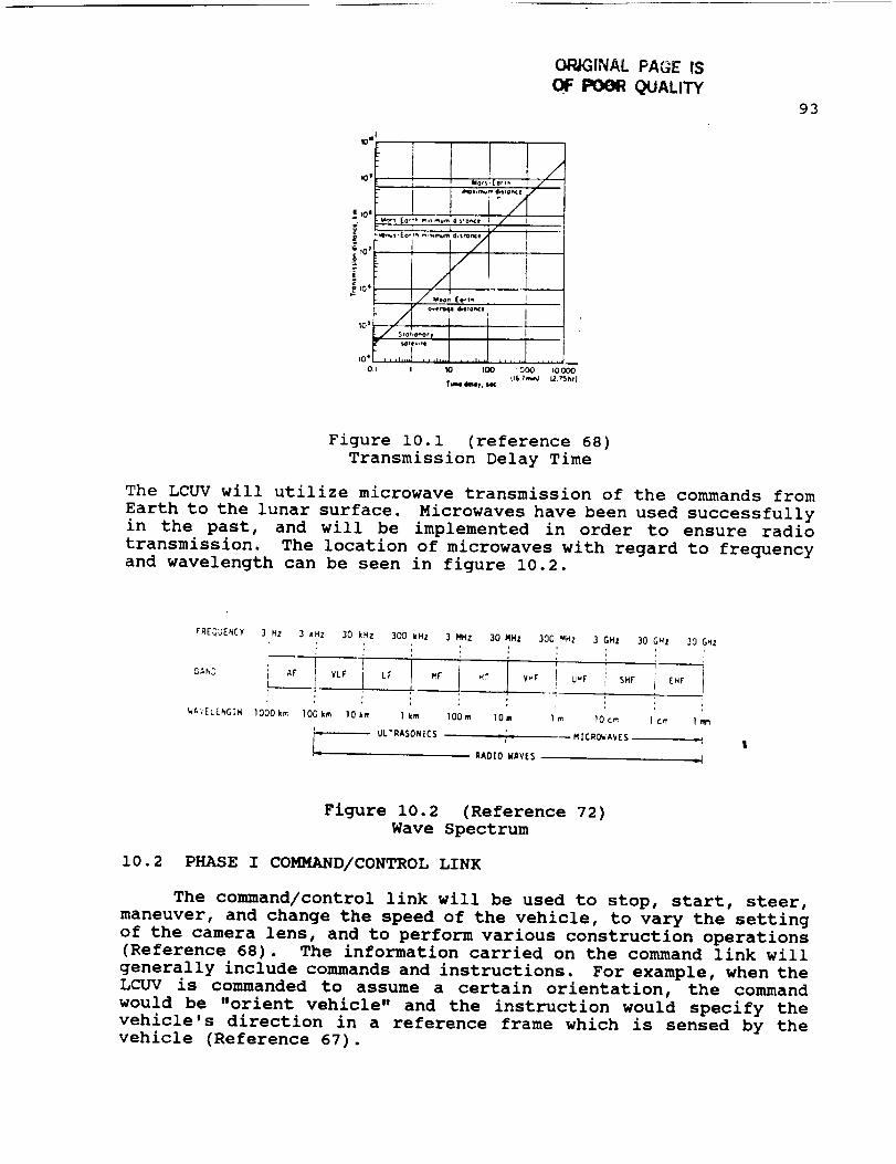
ORdiNAL PAGE IS
OF PO(_ QUALITY
,o.r....3:.,,..J.....J ......J.......j_O, I I 10 IOO : OOO IO.OOO
(16 "_mL_J 12.75_rJt_we 4_,4t, SK
93
Figure i0.i (reference 68)
Transmission Delay Time
The LCUV will utilize microwave transmission of the commands from
Earth to the lunar surface. Microwaves have been used successfully
in the past, and will be implemented in order to ensure radio
transmission. The location of microwaves with regard to frequency
and wavelength can be seen in figure 10.2.
FREQUENCY 3 HZ 3 kHz 30 kHz 300 kHz 3 MHz 30 MHz 300 HHZ
_t",EL[NGTH lO00km lOOkm lOl=m I km lOOm lOre lm
i
J_ UL'T_'SON | CS -"l
UHF
3 GHz 30 GHZ 30 GHz
, , _j
SHF [HF I
10 cm 1 o'n I m_
MICROn, AYES I
Figure 10.2 (Reference 72)
Wave Spectrum
10.2 PHASE I COMMAND/CONTROL LINK
The command/control link will be used to stop, start, steer,
maneuver, and change the speed of the vehicle, to vary the setting
of the camera lens, and to perform various construction operations
(Reference 68). The information carried on the command link will
generally include commands and instructions. For example, when the
LCUV is commanded to assume a certain orientation, the command
would be "orient vehicle" and the instruction would specify thevehicle's direction in a reference frame which is sensed by the
vehicle (Reference 67).

94
In the past, two kinds of command link techniques have been
employed for space vehicles: tone systems and digital systems.
Tone systems can be considered a form of analog transmission. In
the tone-actuated command system, a command tone modulated on a
carrier is transmitted to the space vehicle. This tone is received
and recognized by a filter. The received signal in the filter
output then actuates a switch which leads to the execution of the
command (Reference 67). Digital transmission is the transmittal
of digital pulses between two points in a communications system.
The original source information may already be in digital form or
it may be analog signals that must be converted to digital pulses
prior to transmission and converted back to analog form at the
receive end (Reference 69).
Tone-actuated systems are capable of relaying only a very
small number of different commands (7 to i0 at the most).
Practical systems that have been developed require a 15 kc
bandwidth for 7 tones (Reference 67). The total available command
frequency band at 136 Mc permits only a limited number of about 25
tones (Reference 67). This would require a common use of one
command tone for different space vehicles and leads to the
possibility of causing unscheduled command functions. The tone
system is quite unsecured, and unauthorized commanding of the LCUV
would be rather simple. Another limitation of the tone system is
the required high signal-to-noise ratio of 20 to 30 dB (Reference67).
The foregoing disadvantages have spurred the use of more
digital transmission systems in space vehicles. The primary
advantage of digital transmission is noise immunity. Analog
signals are more susceptible than digital pulses to undesired
amplitude, frequency, and phase vibrations (Reference 69). This
is because with digital, it is not necessary to evaluate these
parameters as precisely as with analog transmission. Instead, the
received pulses are evaluated during a sample interval, and a
simple determination is made whether the pulse is above or below
a certain threshold (Reference 69). Also, digital pulses are
better suited to processing and multiplexing than analog signals.
Digital pulses can be stored easily, whereas analog signals cannot
(Reference 69). Another important feature of the digital system
is that the transmission rate can be easily changed to adapt to
different environments and to interface with different types ofequipment.
Considering the various operations that are involved in the
communication link between Earth and the LCUV, it seems as though
digital transmission will be more effective than the tone system.
Also, the more sophisticated digital system will become more
powerful in the future as technological advances are made in the
field of digital communication. The following is a summary of the
disadvantages and advantages of tone and digital systems that led
to the choice of digital transmittance for the LCUV.

95
Disadvantaqes of tone-aGtuated systems:
- Capable of relaying only a very small number of
different commands
- Total available frequency band permits limited number
of signals
- System is unsecured, and unauthorized commanding is
rather simple
- Requires high signal-to-noise ratio
Advantaqes of diai_al transmission:
- Less susceptible to noise
- Digital pulses can be stored easily
- Transmission rate can be easily changed
- Can easily interface with different types of equipment
Although the LCUV will utilize digital transmission of command
signals, the following is a list of the disadvantages of the
digital system that need to be recognized in the design of the
command/control link:
Disadvantaqes of diqital transmission:
- Requires more bandwidth
- Analog signals need to be converted to digital codes
prior to transmission and converted back to analog atthe receiver
- Requires precise time synchronization betweentransmitter and receiver clocks
- Digital systems are incompatible with existing analogfacilities
(Reference 69)
10.2.1 PULSE MODULATION
Pulse modulation includes many different methods of
transferring pulses from a source to a destination. The four
predominant methods are pulse width modulation (PWM), pulse
position modulation (PPM), pulse amplitude modulation (PAM), and
pulse code modulation (PCM) (Reference 69). These four methods of
pulse modulation are summarized below and shown in Fig. 3.
. PWM. This method is sometimes called pulse duration
modulation (PDM). The pulse width (active portion of
the duty cycle) is proportional to the amplitude of the
analog signal•
• PPM. The position of a constant-width pulse within a
prescribed time slot is varied according to the
amplitude of the analog signal.
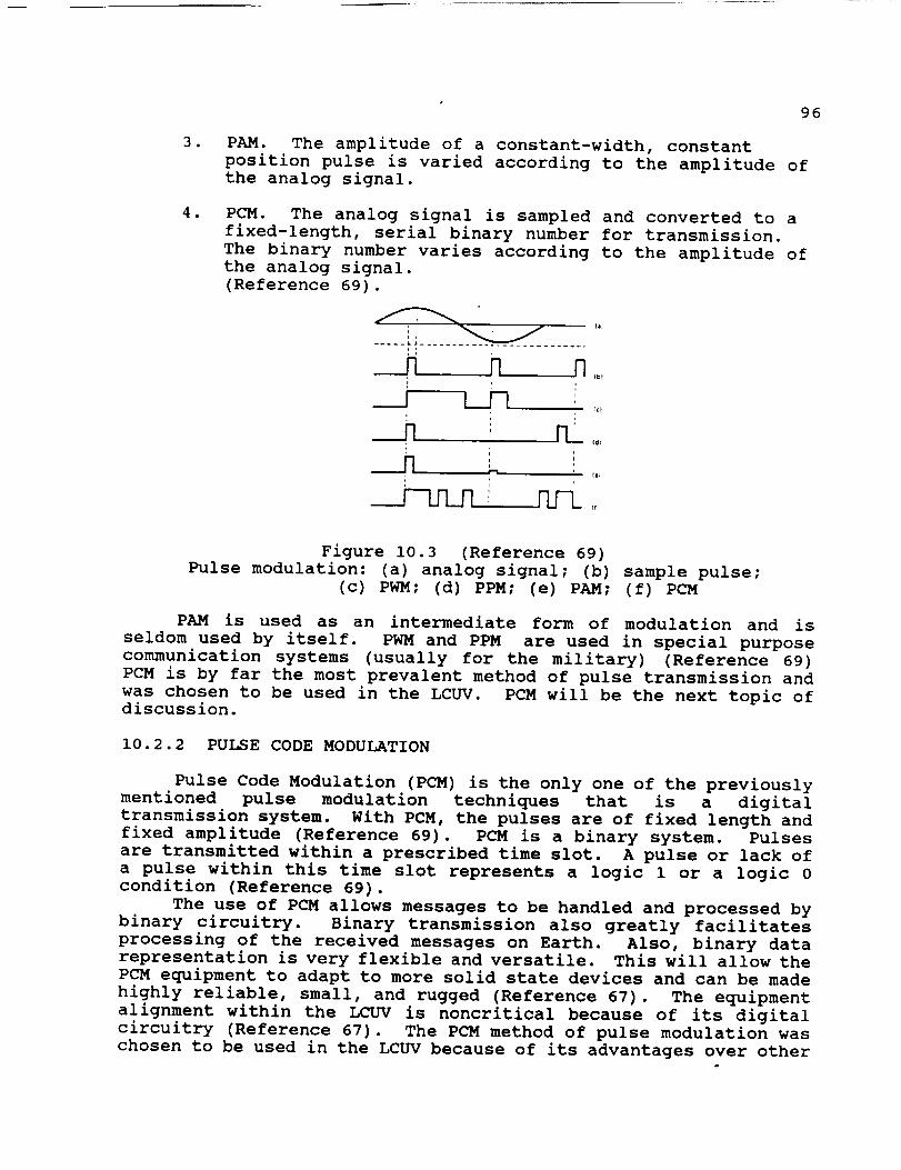
•
.
96
PAM. The amplitude of a constant-width, constant
position pulse is varied according to the amplitude of
the analog signal.
PCM. The analog signal is sampled and converted to a
fixed-length, serial binary number for transmission.
The binary number varies according to the amplitude of
the analog signal.
(Reference 69).
..... , ,- .......... 7 ..............
rc_
,___.n__I1 '
tt_
'r_
Figure 10.3 (Reference 69)
Pulse modulation: (a) analog signal; (b) sample pulse;
(c) PWM; (d) PPM; (e) PAM; (f) PCM
PAM is used as an intermediate form of modulation and is
seldom used by itself. PWM and PPM are used in special purpose
communication systems (usually for the military) (Reference 69)
PCM is by far the most prevalent method of pulse transmission and
was chosen to be used in the LCUV. PCM will be the next topic of
discussion•
10.2.2 PULSE CODE MODULATION
Pulse Code Modulation (PCM) is the only one of the previously
mentioned pulse modulation techniques that is a digital
transmission system. With PCM, the pulses are of fixed length and
fixed amplitude (Reference 69). PCM is a binary system• Pulses
are transmitted within a prescribed time slot. A pulse or lack of
a pulse within this time slot represents a logic 1 or a logic 0
condition (Reference 69)•
The use of PCM allows messages to be handled and processed by
binary circuitry. Binary transmission also greatly facilitates
processing of the received messages on Earth. Also, binary data
representation is very flexible and versatile. This will allow the
PCM equipment to adapt to more solid state devices and can be made
highly reliable, small, and rugged (Reference 67). The equipment
alignment within the LCUV is noncritical because of its digital
circuitry (Reference 67). The PCM method of pulse modulation was
chosen to be used in the LCUV because of its advantages over other

97
pulse modulation techniques. PCMadvantages are summarized on thefollowing page.
Advantaqes of Pulse Code Modulation (PCM):
- Only method suitable for handling digital information
- Uses binary representation (binary data representation
is flexible and versatile)
- PCM equipment is small, reliable, and rugged
- PCM equipment alignment is noncritical
10.2.3 VEHICLE ANTENNAS
The selection of the antenna subsystems to be used on the LCUV
mission is constrained by vehicle orientation, power consumption,
and vehicle geometry. The physical dimensions of the LCUV are
limited, therefore design compromises must be made in the
configurations of the antenna. This will ultimately affect the
area of the antenna gain. Also, the power required to transmit
messages from the vehicle to Earth must be minimal since the power
produced by the fuel cells is an important commodity.
In general, three different missions must be fulfilled by the
LCUV antenna system:
l• High data-rate transmission from vehicle to Earth -
"high gain" antenna
• Low data-rate transmission from vehicle -
"omnidirectional" antenna
• Command transmission from Earth to vehicle -
"omnidirectional" and/or high gain antenna
(Reference 70)
The first mission involves the use of relatively directive
antennas which are pointed at Earth by the vehicle-control system.
this will enable the LCUV to transmit directly to Earth• Another
method assumes the data from the LCUV is being transmitted to Earth
via a parent vehicle as a radio relay. The latter method wouldeliminate the need for a steerable Earth-oriented antenna on the
vehicle and minimize its power requirements (Reference 68).
However, in order to maintain the communication link from the
vehicle to Earth, the use of additional radio relays is apparent
if the vehicle will operate beyond line of sight of the
transmitting parent vehicle.
After considering the design constraints on the antenna
subsystem, the following radio relay design provides the optimum
performance while consuming minimal power during Phase I of the
operation:
The LCUV will be equipped with two omnidirectional antennas.
One will be used to receive transmitted commands directly from
Earth while the other is used to relay data from the LCUV to a
parent vehicle which will transmit the information to Earth• Since

98
there are no power limitations effecting the Earth's commandtransmission, no relay is required and the signals can betransmitted directly to the LCUV. The launched payload that willaccompany the LCUV will act as the parent vehicle which will beequipped with a 4 ft. (1.22 m) reflector directional antenna. Thiswill be a stationary antenna that will be used to relay data fromthe LCUV to Earth. Since the power needed to transmit from theparent antenna to Earth is a function of the effective area of the
receiving antenna, the power source accompanying the transmitter
can be minimal with regard to the large Earth-bound receiver. A
receiving antenna detects an amount of power given by Equation i.
w. = = WT. I41 IR 2 Eq.l (Reference 71)
Where : R = distance from transmitter
WT= transmitter power radiated
\R= receiving antenna effective area
Therefore, the only constraining factor associated with the use of
a large Earth-bound receiver is the cost of construction. It must
be decided whether to transmit a more powerful signal from the
lunar surface thus consuming more power or to limit the power usage
by constructing a large receiving antenna on Earth. Figure 10.4
shows the relationship between the diameter of the receiving
antenna and its probable cost. Therefore, depending on the budget
associated with the LCUV operation, it must be determined which
alternative is more attractive.
00
4O
2O
tO
|
6
e 4o- 3N
Z
I
05
06
04
oz /
OI /
10
m
/--
/_____
//
//
ZO )040 8010100 _.IQO 600LOC_O
Figure 10.4 (Reference 70)
Approximate Antenna Cost

99
10.2.4 TRANSMITTANCE ERROR CORRECTION AND DETECTION
One of the most important features regarding microwave
transmission is command verification. Since the operation of the
LCUV relies entirely on commands received from Earth, it is
important to transmit these messages reliably and accurately. A
command that is interpreted incorrectly might result in a costly
mission loss. Therefore, error correction and detection systems
incorporated into the communication link will provide assuredreliability.
Assuming the command is encoded properly at the Earth base
site, the message is modulated and then transmitted via microwaves
by a directional antenna to the omnidirectional antenna mounted on
the vehicle. In the LCUV, the received signal is demodulated and
decoded; the commands and instruction words with the necessary
synchronization signals are fed to the proper vehicle systems
(Reference 67). Before the commands are executed, it is desirable
to verify the transmitted signal. This verification can be
accomplished by two methods:
. Once the command is received at the LCUV, completeretransmission of the command from the LCUV to the Earth
station can occur where the messages would be compared
in order to detect any errors. Only in the case of
complete matching is an execution transmitted.
• The complete command message can be transmitted and
stored in the LCUV. The message is then transmitted
from Earth a second time; then both messages are
compared in the LCUV. The command is executed only if
the two messages match (Reference 67).
The latter method offers an attractive alternative and will be used
in the LCUV communication link due to the fact that it does not
require as much power consumption as complete retransmission of the
command from the LCUVto Earth. Although this method is more power
efficient, it does require some storage in the vehicle.
One of the most substantial design constraints associated with
the LCUV is the time delay accompanying command transmission. Thetime delay encountered in transmission from the Earth to the LCUV
is approximately 2.3 sec. round-trip. With a vehicle speed of 0.2
m/sec, and a TV frame of i picture every 2.6 sec. lunar round-trip,a picture is received on Earth for each 0.52 m of vehicle motion
(Reference 68). Thus, the LCUV will cover approximately Im between
the time a command is transmitted and the time finally seen by the
Earth-bound base. This time lag problem can be alleviated by
insertion of a predictor function in the control loop and an
indication of the velocity vector on the Earth-based display
(Reference 68). This aspect of the LCUV transmission link will
need to be carefully designed and tested in order to insure
reliable operation of the vehicle.
i00
10.3 PHASE II COMMAND/CONTROL LINK
Phase II of the Lunar Split Mission (Reference i0) involves
the presence of humans on the lunar surface. Once the lunar base
is suitable for astronaut occupancy, the communicationsystem willserve two functions:
i. Provide communication on the lunar surface from basesite to LCUV
2. Provide communication from base site on lunar surface toEarth
These functions will include a voice link from the lunar base to
the LCUV, remote control of the LCUV from the lunar base, and a
voice link from the lunar base to Earth. The need for direct
transmission of commands from Earth to the LCUV will no longer be
required since the vehicle will receive its messages from the lunar
base. The use of pulse code modulation (PCM) for the remote
control of the LCUV from the lunar base will enable the vehicle to
operate without having to change the onboard PCM equipment. This
will also allow the LCUV to receive messages directly from Earth
if ever the need arises. Therefore, the communication system will
become more flexible and integrated during Phase II of the LCUVoperation.
10.3.1 VEHICLE ANTENNAS
During Phase II of the operation, the LCUV antenna subsystem
will consist of two omnidirectional antennas mounted on the vehicle
along with the reflecting antenna accompanying the parent vehicle.
These antennas will serve two purposes:
i. Provide means for remote control of LCUV from the lunarbase
2. Provide voice link from LCUV to lunar base
The I/2UV will need to operate within the line of sight of the
lunar base in order to eliminate the need for radio relays on the
lunar surface. Transmitting and receiving antennas on masts of 30
and 60 m tall, respectively, will permit point-to-point
communication (to the horizon) over a path of less than 15 km.
(Reference 68). Figure 10.5 shows the lunar horizon distance
nomogram relating antenna size to transmittance distance.

i01
(meters)
1_0
lOg-
60
30.
I0,
G.
3'
2.
Luaarho-,:o_ _,L+o_cn
4_
"¢0
35
-50
2_
- ZO
: I$
S
0
lleCt;uing
Ilef enno he _ghtImtTml)
150
.IO0
• 6O
-20
-10
-I
3
2
0
Figure 10.5 (Reference 68)
Lunar Horizon Distance Nomogram
As the LCUV mission progresses, the addition of radio relays
can be implemented in order to provide a wider range of LCUV
operation. Also, reliable communication over i00 km distances can
be obtained by ground-wave propagation, using the lower frequency
portion of the spectrum (Reference 68).
10.4 CONCLUSION
The use of an efficient and reliable communication link from
Earth to the lunar surface is an essential aspect of the LCUV.
The system proposed for the LCUV involves the use of digital
microwave transmission and pulse code modulation (PCM). Command
verification and error detection will be incorporated into the
system in order to ensure reliable and accurate transmission. The
antenna configurations include two omnidirectional antennas mounted
on the LCUV and a 4 ft (1.22 m) reflector antenna used for
transmission to Earth from the parent vehicle located on the lunar
surface. After considering each alternative available for
designing a communication link, the most practical and economical
methods were chosen. Before this system can be used, it must first
be thoroughly tested and proven reliable since it will be the only
means of communicating with the LCUV after it is launched. Failure
of the communication link will result in total failure of the LCUV
mission. Therefore, careful design and exacting detail are
required in order to ensure a successful operation.
102
11 •0 MECHANICAL ARM
The primary design driver for the Lunar Construction Utility
Vehicle (LCUV) is its ability to perform a wide variety of
construction tasks (Reference I0). The mechanical arm (MA) is an
important component because of the need to perform many of the
various tasks. These tasks will be accomplished by a variety of
attachments. The two main attachments that are of primary
importance for the lunar mission are the backhoe device and the
hoisting mechanism. The backhoe will be responsible for excavating
on the lunar surface. The hoisting devices primary concern is the
ability to lift certain modules such as:
I. Habitation module
2. Materials processing
3. Interconnect Nodes
4. Airlock
5. Flexible tunnels
(Reference I0)
These main attachments and others will be discussed in greater
detail in a latter section of this report. These attachments will
be designed so that they can be easily interchanged on the
mechanical arm. Our primary goal is to develop a mechanical arm
that will facilitate excavating and hoisting processes for the
phase one development of a Lunar Base facility. The following
steps were taken for the development of the mechanical arm.
i. Establish the general design requirements, constraints,
and limitations.
2. Investigation of the lunar environment; i.e., soil for
excavating purposes, reduced gravity, and frequent
temperature changes, etc.
3. Investigation of actuation systems - electrical and
hydraulic.
4. Investigation of controls; i.e., thermal and MA.
5. Specific attachments of arm.
6. Design and analysis of arm.
ii.I ASSUMPTIONS AND DESIGN CONSTRAINTS
The two main drivers for the sizing of this arm are the height
of the lunar lander and the optimum partial burial depth for
application of the radiation shielding material. The MA is 15 m
in length from its base to the point of attachment of the backhoe
or hoist implements. These two main attachments, the backhoe and
hoist implements, will serve a number of purposes during the early
construction phases of the lunar base. The backhoe attachment will
have a holding capacity of 0.6m 3 with dimensions to be specified
later in the report. The time required to excavate 500m 3 of soilwill be 48 hours. This assumes three and one half minutes to fill
the backhoe and empty it into the side-dump box or onto the lunar

103
surface. If a partially buried environment is required, thebackhoe system will be utilized. If the modules are to be placedon the surface, then the backhoe could not be used because therequired length of the MA would be too long to allow thedistribution of regolith along the top of the habitation module.The backhoe will be able to perform some site preparation such asthe clearing of large lunar rocks which may be required prior totransport of the habitation module from the landing site to thelunar base site.
The crane attachment is better defined as a series ofattachments associated with crane or hoisting processes. Anattachment for the Lunar Telerobotic Servicer (LTS) will berequired to give the LTS access to places it would not have accessto from its position of the LCUV. A forklift attachment will beimplemented for lifting relatively small payloads or engine palletsfrom the lander and transferring them to an LCUV for transport tothe lunar base site. The hoisting mechanism may be used to aid inthe placement and connection of habitation modules and moduleinterconnect nodes during expansion of the lunar base. It issuggested that the backhoe and the required crane attachments behoused in a tool crib which retains them in the required positionfor the MA to change from component to component quickly andeasily. If a number of different tasks are to be carried out inthe same area, this crib could travel on an LCUV and remain on siteduring the process (Reference i0).
Besides the constraints and limitations developed in theprevious section of this paper, there are other environmentalconstraints which pose serious problems. For example, thermalcontrol of the arm. The heat generated by the drive motors andelectronics of the arm system will have to be dissipated duringall operations. The development of a radiator for the LCUV will
hopefully aid in the solution to this problem. Lunar soil and dust
is another problem. It could be a very serious problem if the dust
or soil enters the manipulator arm joints. A protective covering
for the joints will have to be developed. This covering must not
inhibit the mobility of the arm to perform the required
construction tasks. Another design problem is the fact that
construction vehicles with mechanical arms have not been developed
for Lunar use. This caused a problem in locating information on
mechanical arms with construction capabilities that can operate in
the Lunar environment. A majority of the information that will be
used in the development of the MA is from the Remote Manipulator
System (RMS) on the Space Shuttle. This is the only Manipulator
system that is presently being used in space. Much of the control
aspects of the MA will be developed similar to the RMS. The final
constraint and most dominant is the absence of human operators
during the unmanned phase of exploration and surface preparation
(Reference 73). One solution to this problem is the use oftelerobotics.
104
Some other constraints that must be considered are:
i
u
e
Mechanical simplicity
Minimal weight
Adaptability to task changes
Robotic maintenance and repair
Major concerns:
m
i
Power needed for hoisting and digging to be
accomplished
Heat dissipation of motors
Assurance that vehicle will not tip over when liftingis being performed
Added Assumptions:
i
i
m
Motors capable of providing required torque
Deployable spades available to provide support
Length of arm booms
Thermally controlled
Able to work in harsh environment with minimal
maintenance
A promising design of a MA will be one that takes advantage
of the lunar environment and will operate within the constraints
it imposes (Reference i0). Current terrestrial construction
equipment such as the bulldozers and backhoes typically depend on
weight for counter balance and the reaction to the application
force. The fact that the moon has a gravitational field 1/6 that
of the Earth presents another problem in producing traction forces
with such equipment, since the normal forces created by the vehicle
will be less on the moon. This gravitational constraint leads to
the next topic, the lunar environment.
11.2 LUNAR ENVIRONMENTAL EFFECTS
The mechanical arm must be designed to work in the severe
lunar environment. This environment is characterized by:
I
Lack of atmosphere
Reduced gravity (1/6 of the earth)
Diversity of soil
Exposure to solar and galactic cosmic radiation
Exposure to dust and visibility problems
Extreme temperature fluctuations (-170"C to 130"C )
The 1/6 reduction of gravity causes a major problem with the
lifting of objects. To create the necessary opposing force
required to perform the task of lifting or excavating on the lunar
surface, the mechanical arm module will incorporate two deployable
spades. The volume displaced by these spades to support the fully
105
loaded MA is 1 m3 per spade. If the load is to be moved a distance
around the center of gravity of the LCUV, then two more deployable
structures utilizing only support pads may be mounted opposite to
the spades. Each of these systems will be a fixed part of the MA
module and will be contained on the module when not in use. They
may be driven into the lunar surface using the backhoe attachment,
but they must also be able to retract to accommodate the MA use as
a crane. To simplify the removal of the spades, the MA may provide
locomotion in the direction of the spades thus pulling them free
from the regolith (Reference i0).
The lunar soil can be described as well-graded silty sands
with an average particle size between 0.040 and 0.130 mm. The
density of in situ bulk lunar soil, as determined from large
diameter core tube samples, is typically 1.4 to 1.9 g/cm 3. The
bulk density increases to support the overburden in lunar gravity.
Spheres, angular shards, and fragile reentrant vesicular grains are
among the diverse shapes found in most lunar soils. The most
abundant particles composing the soil are igneous or breccia lithic
grains, mineral grains, glass fragments, and the unique lunar
agglutinates (Reference 74).
Some important environmental factors are the fluctuations in
temperature of a lunar day and the effects of radiation during the
day. Thermal control and radiation shielding will be developed tocompensate for these factors. These are the conditions that the
mechanical arm will face in the lunar environment.
11.3 BACKGROUND
A robotic manipulator may be defined as a multidegree of
freedom open-loop chain of mechanical linkages and joints. It is
designed to perform mechanical operations which normally require
the manipulative skills of humans. These mechanisms, driven by
actuators, are capable of moving an object from initial to final
locations or along prescribed trajectories (Reference 75).
Remotely operated robotic manipulator arms are used in all
types of applications. The only arm in space that is presently
being used is the Remote Manipulator System (RMS) on the shuttle.
Since this is the case, much of the information used to design
the mechanical arm for the L cur has come from this existing design.
The development of the RMS was done by SPAR Ltd. in Canada. The
manipulator system, the results of a cooperative program between
the National Research Council of Canada (NRCC) and NASA, consists
of the arm, a display and control panel, (including 2 hand
controllers), and a manipulator controller unit that interfaces
with the Orbiter computer (Reference 76). The RMS is Canada's
contribution to the space program. In return for the RMS, NASA
signed an agreement to buy other flight units from Canada. The
agreement will also give Canada a price break on shuttle launches.
NASA also agreed not to contract with any other firm to build a
competitive system. The arm is presently being used aboard the
shuttle to retrieve and service satellites. On later missions the
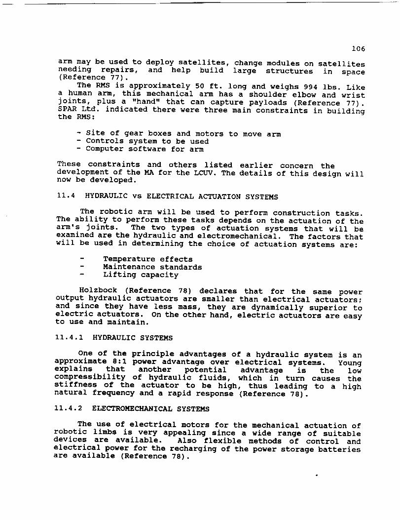
106
arm may be used to deploy satellites, change modules on satellitesneeding repairs, and help build large structures in space(Reference 77).
The RMS is approximately 50 ft. long and weighs 994 ibs. Likea human arm, this mechanical arm has a shoulder elbow and wristjoints, plus a "hand" that can capture payloads (Reference 77).SPAR Ltd. indicated there were three main constraints in buildingthe RMS:
- Site of gear boxes and motors to move arm- Controls system to be used- Computer software for arm
These constraints and others listed earlier concern thedevelopment of the MA for the LCUV. The details of this design willnow be developed.
11.4 HYDRAULIC vs ELECTRICAL ACTUATION SYSTEMS
The robotic arm will be used to perform construction tasks.The ability to perform these tasks depends on the actuation of thearm's joints. The two types of actuation systems that will beexamined are the hydraulic and electromechanical. The factors thatwill be used in determining the choice of actuation systems are:
D Temperature effectsMaintenance standards
Lifting capacity
Holzbock (Reference 78) declares that for the same power
output hydraulic actuators are smaller than electrical actuators;
and since they have less mass, they are dynamically superior to
electric actuators. On the other hand, electric actuators are easy
to use and maintain.
11.4.1 HYDRAULIC SYSTEMS
One of the principle advantages of a hydraulic system is an
approximate 8:1 power advantage over electrical systems. Young
explains that another potential advantage is the low
compressibility of hydraulic fluids, which in turn causes the
stiffness of the actuator to be high, thus leading to a high
natural frequency and a rapid response (Reference 78).
11.4.2 ELECTROMECHANICAL SYSTEMS
The use of electrical motors for the mechanical actuation of
robotic limbs is very appealing since a wide range of suitable
devices are available. Also flexible methods of control and
electrical power for the recharging of the power storage batteries
are available (Reference 78).

107
11.4.3 TEMPERATUREEFFECTS
The lunar environment is exceedingly different from that of
the earth. The temperature ranges from approximately -140"C to
150°C. Young's research notes that it is desirable that a dual
purpose temperature stabilizing system, which can either heat or
cool, should be used in such cases. Motors and fans used in lunar
equipment are cooled with the aid of heat-dissipating coatings of
beryllium oxide microspheres in silicon rubber. The temperature
dependency of hydraulic system fluid viscosity could cause a
problem with performance of the system since at extremely cold
temperatures the fluid becomes very viscous and may freeze.
The most commonly used electromechanical system is the permanent
magnet DC brushless motor. Permanent magnets have a physical
property known as the Currie Point. This occurs when a magnet
loses its magnetism immediately upon reaching a critical
temperature. The magnetic material consists of Neodymium, Iron,
and Boron and has a Currie Point between 120°C and 150°C. This
could cause a problem because it is just within the limits of the
maximum lunar temperature range. As mentioned earlier, this
problem could be avoided by the use of heat dissipating coatings.
11.4.4 MAINTENANCE STANDARDS
The electromechanical actuator is virtually maintenance free,
whereas, the hydraulic system has critical filtering requirements.
Another factor concerning the maintenance of the hydraulic system
is that the fluid it uses must remain particle free. These strict
requirements make the electromechanical system the better suited
for lunar application. As stated in Reference 79:
"Hydraulic systems should not be used on the Moon due to
the high maintenance requirements anticipated resulting
from the vacuum, high radiation, and regolith dustenvironment".
11.4.5 LIFTING CAPACITY
The ability to lift is increased with the use of a hydraulic
actuating system than with an electromechanical system. This is
known to be true because of the estimated 8:1 power advantage of
the hydraulic system. Although this is an important factor, this
becomes less of an advantage on the moon because of the 1/6 gravity
reduction, which allows the electromechanical system to have 6
times greater lifting capacity than on the earth. See Table Ii.i
for a comparison of these two systems.
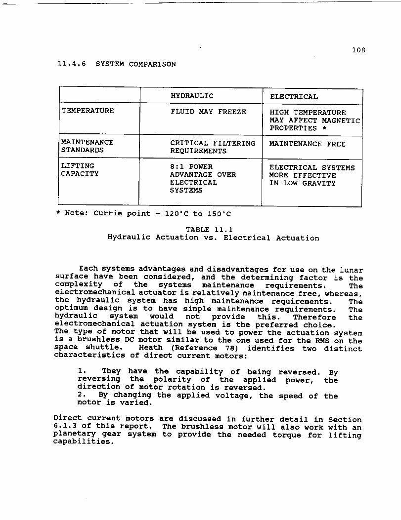
11.4.6 SYSTEM COMPARISON
108
TEMPERATURE
MAINTENANCE
STANDARDS
LIFTING
CAPACITY
HYDRAULIC
FLUID MAY FREEZE
CRITICAL FILTERING
REQUIREMENTS
8:1 POWER
ADVANTAGE OVER
ELECTRICAL
SYSTEMS
ELECTRICAL
HIGH TEMPERATURE
MAY AFFECT MAGNETIC
PROPERTIES *
MAINTENANCE FREE
ELECTRICAL SYSTEMS
MORE EFFECTIVE
IN LOW GRAVITY
* Note: Currie point - 120°C to 150°C
TABLE ii.i
Hydraulic Actuation vs. Electrical Actuation
Each systems advantages and disadvantages for use on the lunar
surface have been considered, and the determining factor is the
complexity of the systems maintenance requirements. The
electromechanical actuator is relatively maintenance free, whereas,
the hydraulic system has high maintenance requirements. The
optimum design is to have simple maintenance requirements. The
hydraulic system would not provide this. Therefore the
electromechanical actuation system is the preferred choice.
The type of motor that will be used to power the actuation systemis a brushless DC motor similar to the one used for the RMS on the
space shuttle. Heath (Reference 78) identifies two distinctcharacteristics of direct current motors:
i. They have the capability of being reversed. By
reversing the polarity of the applied power, thedirection of motor rotation is reversed.
2. By changing the applied voltage, the speed of themotor is varied.
Direct current motors are discussed in further detail in Section
6.1.3 of this report. The brushless motor will also work with an
planetary gear system to provide the needed torque for liftingcapabilities.
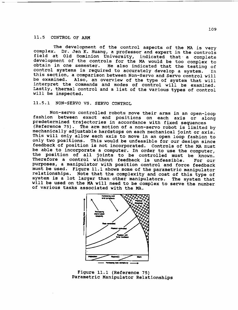
109
11.5 CONTROLOF ARM
The development of the control aspects of the MA is verycomplex. Dr. Jen K. Huang, a professor and expert in the controlsfield at Old Dominion University, indicated that a complete
development of the controls for the MA would be too complex to
obtain in one semester. He also indicated that the testing of
control systems is required to accurately develop a system. In
this section, a comparison between Non-Servo and Servo control will
be examined. Also, an overview of the type of system that will
interpret the commands and modes of control will be examined.
Lastly, thermal control and a list of the various types of controlwill be inspected.
Ii. 5.1 NON-SERVO VS. SERVO CONTROL
Non-servo controlled robots move their arms in an open-loop
fashion between exact end positions on each axis or along
predetermined trajectories in accordance with fixed sequences
(Reference 75). The arm motion of a non-servo robot is limited by
mechanically adjustable hardstops on each mechanical joint or axis.
This will only allow each axis to move in an open loop fashion to
only two positions. This would be unfeasible for our design since
feedback of position is not incorporated. Controls of the MA must
be able to incorporate a computer. In order to use the computer,
the position of all joints to be controlled must be known.
Therefore a control without feedback is unfeasible. For our
purposes, a manipulator with position control and force feedback
must be used. Figure ii.i shows some of the parametric manipulator
relationships. Note that the complexity and cost of this type of
system is a lot larger than other manipulators. The system that
will be used on the MA will need to be complex to serve the numberof various tasks associated with the MA.
r
Figure ii.i (Reference 75)
Parametric Manipulator Relationships
ii0
Servo controlled robots incorporate feedback devices on thejoints or actuators of the manipulator which continuously measurethe position of each axis (Reference 75). With the feedbackdevices incorporated, it will permit the control to stop each axisof the manipulator at any point within its total range, rather thanonly two positions that non-servo control can obtain. Servo controlrobots have a more manipulative capability than non-servo controlrobots in the sense that they are able to position a tool or agripper (i.e. backhoe & hoist) anywhere within the workspace. Thecontrollers of non-servo robots may be electronic sequencers,minicomputers, or microprocessors based on the control systemsneeded. This class of control systems has magnetic or solid stateelectronic memory devices for storing a taught sequence of motionsin digital form. For example, if a simulation of the arm wasperformed on earth, the computer could store these movements forlater use. This type of servo control will be used for the MA ofthe LCUV.
One type of servo control is the 'Continuous Path Control'. This
type of control is used where continuous path of the end-effector
or attachment (i.e. backhoe & hoist) is of primary importance to
the application. The continuous path motions are produce by
interpolating each joint control variable from its initial value
to the desired final value (Reference 75). This process allows for
minimal movement of each joint in attaining the final positions.
This will give the MA a controlled predictable path. All of the
joints' variables are interpolated to complete the motions
simultaneously, thus giving a coordinated joint motion (Reference
v5).The three basic continuous path controls that will be used
are as follows:
i. Conventional Servo Control - This control uses no information
about where the path goes in the future. The controller may have
a stored representation of the path it is to follow, but to
determine the device signals to the arm's brushless dc motors and
planetary gear system, all calculations will be based on the
past and present tracking error.
2. Preview/Feedforward Control - This control uses some knowledge
about how the path changes immediately ahead of the robot's current
location, in addition to the past and present tracking error that
will be used by the servo controller.
3. Path Planning/Trajectory Calculation - this control involves
using an available description of the path the manipulator should
follow from one point to another.
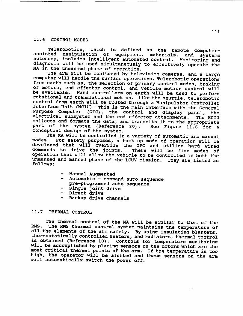
iii
11.6 CONTROLMODES
Telerobotics, which is defined as the remote computer-assisted manipulation of equipment, materials, and systemsautonomy, includes intelligent automated control. Monitoring anddiagnosis will be used simultaneously to effectively operate theMA in the unmanned phase of operation.
The arm will be monitored by television cameras, and a largecomputer will handle the surface operations. Telerobotic operationsfrom earth such as, the selection of primary control modes, brakingof motors, end effector control, and vehicle motion control willbe available. Hand controllers on earth will be used to performrotational and translational motion. Like the shuttle, teleroboticcontrol from earth will be routed through a Manipulator ControllerInterface Unit (MCIU). This is the main interface with the GeneralPurpose Computer (GPC), the control and display panel, the
electrical subsystem and the end effector attachments. The MCIU
collects and formats the data, and transmits it to the appropriate
part of the system (Reference 80). See Figure 11.6 for a
conceptual design of the system.
The MA will be controlled in a variety of automatic and manual
modes. For safety purposes, a back up mode of operation will be
developed that will override the GPC and utilize hard wired
commands to drive the joints. There will be five modes of
operation that will allow the vehicle to be controlled in both the
unmanned and manned phase of the LCUV mission. They are listed as
follows:
- Manual Augmented
- Automatic - command auto sequence
pre-programmed auto sequence
- Single joint drive
- Direct drive
- Backup drive channels
11.7 THERMAL CONTROL
The thermal control of the MA will be similar to that of the
RMS. The RMS thermal control system maintains the temperature of
all the elements of the arm safely. By using insulating blankets,
thermostatically controlled heaters, and radiators, thermal control
is obtained (Reference i0). Controls for temperature monitoring
will be accomplished by placing sensors on the motors which are the
most critical thermal points of the arm. If the temperature is too
high, the operator will be alerted and these sensors on the arm
will automatically switch the power off.
112
11.8 OTHER CONTROLS
The following is a list of various controls that will beimplemented in the operation of the MA:
- Control for motor strain
- Bucket attachment sensors used to control its speed
of closure
- Displacement lag control
- Accelerometer used to prevent arm collisions with
foreign objects (ie. lunar rocks, other LCUV's etc.)
11.9 INDIVIDUAL JOINT CONTROL
All linear motions must be made by combined rotations of
various joints just as the human arm does (Reference 77). Each
joint of the arm will have a complex array of gears and motors that
not only have to move the arm into proper position, but they must
compensate for wobbling resulting from movement of the LCUV.
ii. I0 ATTACHMENTS
A backhoe attachment will be used primarily for excavation of
soil and soil handling for site preparation. This includes
digging, trenching, and leveling of the lunar surface. The backhoewill be attached to the end of the mechanical arm. The backhoe
will consist of two independent quarter circle type buckets
arranged so as to generate equal and opposite forces for either
digging or clamping. The soil will first be cultivated using a
rotary device with sharp blades that can be attached to the rearof the vehicle. Then the arm will drive the bucket into the soil
for excavation purposes. A worm gear system will be used to openand close the bucket attachment. A clockwise or counter-clockwise
motion of the worm gear will cause this effect. The bucket will
be equipped with sensors that will detect strains resulting from
the attempted opening or closing of the attachment. If a maximum
strain is exceeded, the power will be terminated,
A tiller will be used to cultivate the soil prior to
excavation by use of the bucket attachment. This tiller is
designed so that it can hook on to the connection link of the LCUV
and then be pulled across the lunar surface. There will be anumber of circular blades that will rotate on an enclosed axle.
The axle is enclosed to prevent lunar dust from inhibiting therotation of the device.
Finally, a blade attachment will be used to push and level thelunar soil. It will be attached to the LCUV via the connection
link.

113
ii.ii HOISTING MECHANISM
This attachment will be used for lifting the habitationmodule, materials processing modules, and interconnect nodes.The attachment will utilize a hook device. This hook can beinserted into a circular fixture located on the specific modulesthat need to moved. Pre-flight simulation tests must be conductedin order to ensure reliable operation of these attachments on thelunar surface.
11.12 CONCLUSION
The development of the mechanical arm was very complex.Many aspects were considered, such as constraints and assumptionswhich played a major role in the design. The major concern wasthe power requirements needed to hoist and dig on the lunarsurface. An assumed maximum load of 6450 N was applied to the endof the arm at a distance 6.56 m away from the vehicle so that thevehicle would not tip. An assumed maximum moment was determined.From this moment an assumed maximum torque needed for the motorsfor lifting capabilities of the arm was determined. The overalldesign of the arm will include :
- Three booms totaling 15m with 3 degrees of freedom- Electrical Actuation System- Servo Control "Continuous Path Control"
- Two main attachments ( Hoist and Digging Mechanism)
- Brushless D.C. Motors with planetarygear set.
The present design will need much more design and analysis before
it will be a complete design. Tests and simulations must be
performed to ensure a safe and reliable arm.
114
12.0 OPTICAL SYSTEM
The Lunar Construction Utility Vehicle (LCUV) is required to
operate both manually and remotely from an Earth based station.
It is during the un-manned mission that the use of proper lighting
packages, camera configurations, and a means of positiondetermination is crucial.
The problems that will be discussed in the assumptions and
design constraints section demand the use of an adequate means of
lighting for both lunar day and night situations. There are
several ways that the lighting packages may be situated on the
LCUV, many of these configurations will be looked into and the
arrangement that best fits the constraints will be chosen.
A large amount of information that will aid the Earth station
in maneuvering the vehicle will be provided by the cameras that
will be mounted on the LCUV. Like the lighting packages, the
cameras can be arranged in many different ways. The arrangement
that best optimizes power usage and complies with the designconstraints will be selected.
The position of the vehicle and the distance an object is away
from the vehicle is information that will be required by the Earth
station when guiding the vehicle. The instrument that will be
determining this information will have to contend with theunfavorable environmental conditions of the Moon in addition to
producing reliable data. There are numerous method by which this
task can be accomplished. Some of the more favorable rangefinding
techniques are by the use of microwave or laser. Each of these
options must be looked into and the option that both produces the
most reliable data and maximizes power utilization will be
employed.
12.1 ASSUMPTIONS AND DESIGN CONSTRAINTS
Much of the restrictions that are established for guidelines
in designing the lighting configurations and navigational aids are
set by the environment and composition of the Moon's surface
(Reference I0). Because the moon does not have an atmosphere, as
the Earth does, diffuse reflection of light (light scattering) is
not possible (Reference i0). This causes areas which are brightly
illuminated contrasted by areas of vast shadowing. An additional
problem that is presented is what is called washout (Reference i0).
Washout is caused when light impinges upon the Moon's surface
within 30 of the normal of the surface, when this occurs the light
reflects back to space and none is diffusely reflected. The one
major aspect of the Moon's surface composition that presents a
design restriction is its ability to reflect light. Albedo is a
measure of the reflective ability of substance. The Moon's albedo
rating is roughly 9% (Reference i0).

115
Design Constraints:
Q
Temperature ranging -171°C to III°C.Effects associated with solar flares and radiation.
Effects associated with the lack of atmosphere.
Limited diffuse reflection of incoming light.
Shadowing.
Washout.
Moving down light.
Low albedo rating of Moon's surface.
Minimal power consumption
12.2 LIGHTING ARRANGEMENT
Since the main object in designing the lighting packages to
be used on the LCUV is to maintain a low power draw from the fuel
cells, it is essential that the lights are mounted to optimize thearea that is covered. Another item that must be considered is that
the conditions for lighting needs during the unmanned mission aredifferent than that of the manned mission. The constraints that
were mentioned beforehand that were set by the environment of the
Moon will primarily effect the angular range of tilt that the
lights are capable of. In order to avoid to effects of shadowing
the lights will have to be mounted a sufficient distance above the
surface.
The arrangement that has been decided upon for use on the LCUV
(see figure 12.1) is comprised of four lights mounted 5 feet and
having the capability of extending to i0 feet above the surface on
each corner of the vehicle giving the capacity of illuminating any
area around the vehicle. Each of the lights are capable of a
lighting power of 200 lumens which is sufficient during the worst
case situation of the lunar night. The stands which support the
lights will have the ability of 360" rotation in the horizontal
plane, this will aid in concentrating light on certain areas. A
camera and rangefinder arrangement is included on each stand for
a diversity of views. For a maximum range of
view, the camera/light/rangefinder arrangement will have an angular
tilt ability in the vertical direction ranging from 60" below thehorizon and 60" above the horizon.
In addition to the above mentioned lighting arrangement a
light stand will be located in the center of the vehicle that will
support the main camera and rangefinder arrangement. This
particular stand will have the capability of extending to a height
of 15 feet above the surface for long range viewing. Similar to
the corner stands, the main stand is capable of 360 ° rotation and
vertical tilts ranging from 60" below horizon and 60" abovehorizon.

116
Figure 12.1LCUV Arrangement of Optical Aids.
117
12.3 C_E_S
The camera system that is going to be put to use on the LCUVhas to have the following capabilities:
m
i
m
Automatic focus
Wide range of view
Switching capability (transmit one or more views)
Transmit pictures of all working cameras
every six seconds.
Automatic attenuation to light conditions
The cameras will be aligned in the way that is shown in figure
as was described previously. An actual working camera that works
under the conditions specified in the design constraints section
of this report has not been found as of now but one that is capable
is possible.
12.4 NAVIGATION AND RANGEFINDING
Accurate vehicle to object data in aiding the navigation of
the LCUV is essential. There are many methods by which this can
be accomplished all of which use the basic concept of time of
flight of a waveform. First, a signal in the form of a wave ofsome sort is sent out. The time that is consumed before the wave
returns is then measured. With this information, in addition to
the speed of the wave, the total distance traveled can be
determined. This distance is actually twice the distance between
the object and the source/collector of the waves. The waveforms
that will be considered are microwave, and light (i.e. laser).
The major drawback associated with the use of microwave radar
rangefinders is that they suffer from diffraction, there is limited
angular resolution for a given antenna and reflector size
(Reference 82). This limits the accuracy that can be attained when
trying to range on the moons surface. Since the accuracy of the
data that is acquired is of utmost importance for navigational
purposes the microwave radar rangefinding device will not beconsidered hereafter.
The laser rangefinding device is capable of achieving
remarkable accuracies using the same principle of measurement that
is used in the microwave radar rangefinder, that being the time of
flight response phase delay measurement method described
previously and also shown in figure 12.2. The reason why the laser
rangefinding device is capable of better accuracies than the
microwave radar device is because of the properties of the
waveforms that are used. As described previously, the microwave
is susceptible to diffraction as when the wave impinges upon a
small or unpolished surface whereas the laser light beam is
concentrated and does not diffract (i.e., the beam is coherent)
(Reference 85).

118
The LCUV will have five laser rangefinders (one on the mainstand and four on each of the four corners stands of the vehicle)that will be used; when they are not in use they will be turned
off in order to conserve power.
Figure 12.2 (Reference 82)
Time-of-Flight of a laser pulse from
a laser rangefinder.
Figure 12.3
Corner optical aid arrangement.
One arrangement per corner of
the vehicle.
! +
+,-.-+i'
2-
Figure 12.4
Preliminary optical array.
Located in the center of
the vehicle.
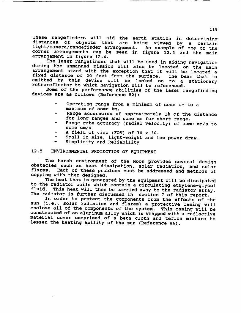
119
These rangefinders will aid the earth station in determiningdistances of objects that are being viewed by a certainlight/camera/rangefinder arrangement. An example of one of thecorner arrangements can be seen in figure 12.3 and the mainarrangement in figure 12.4.
The laser rangefinder that will be used in aiding navigationduring the unmanned mission will also be located on the mainarrangement stand with the exception that it will be located afixed distance of 20 feet from the surface. The beam that isemitted by this devise will be locked on to a stationaryretroreflector to which navigation will be referenced.
Some of the performance abilities of the laser rangefindingdevices are as follows (Reference 82):
m
Operating range from a minimum of some cm to amaximum of some km.
Range accuracies of approximately i% of the distance
for long ranges and some mm for short range.
Range rate accuracy (radial velocity) of some mm/s to
some cm/s
A field of view (FOV) of 30 x 30.
Small in size, light-weight and low power draw.
Simplicity and Reliability
12.5 ENVIRONMENTAL PROTECTION OF EQUIPMENT
The harsh environment of the Moon provides several design
obstacles such as heat dissipation, solar radiation, and solar
flares. Each of these problems must be addressed and methods of
copping with them designed.
The heat that is generated by the equipment will be dissipated
to the radiator coils which contain a circulating ethylene-glycol
fluid. This heat will then be carried away to the radiator array.
The radiator is further discussed in section 7 of this report.
In order to protect the components from the effects of the
sun (i.e., solar radiation and flares) a protective casing will
enclose all of the components of the system. This casing will be
constructed of an aluminum alloy which is wrapped with a reflective
material cover comprised of a beta cloth and teflon mixture to
lessen the heating ability of the sun (Reference 86).

120
12.6 CONCLUSIONS
After considering all of the design constraints that were setupon the development of the optical means of the LCUV theconfiguration shown in figure 12.1 was chosen for utilization.The lighting, viewing by camera and distance determination of thevehicle by a choice of five different light/camera/rangefinderconfiguration stands gives optical analysis capabilities of anypoint around the vehicle by at least three cameras.
The laser rangefinder that will be used in conjunction with astationary retroreflector will aid the Earth based station in thenavigation of the vehicle by position determination and tracking.The way that this system will be controlled has not as of yet beendetermined although it is known to be possible.
All of the components that were discussed will be protectedfrom the harsh environment of the Moon by a protective casing anda reflective thermal cover. The heat that is generated by thedevices will be first conducted to the radiator coils and thencarried away by the working fluid to the radiator array.
Although the system has not been entirely designed theconcepts that have been introduced are credible and do abide bythe design constrains that have been outlined.
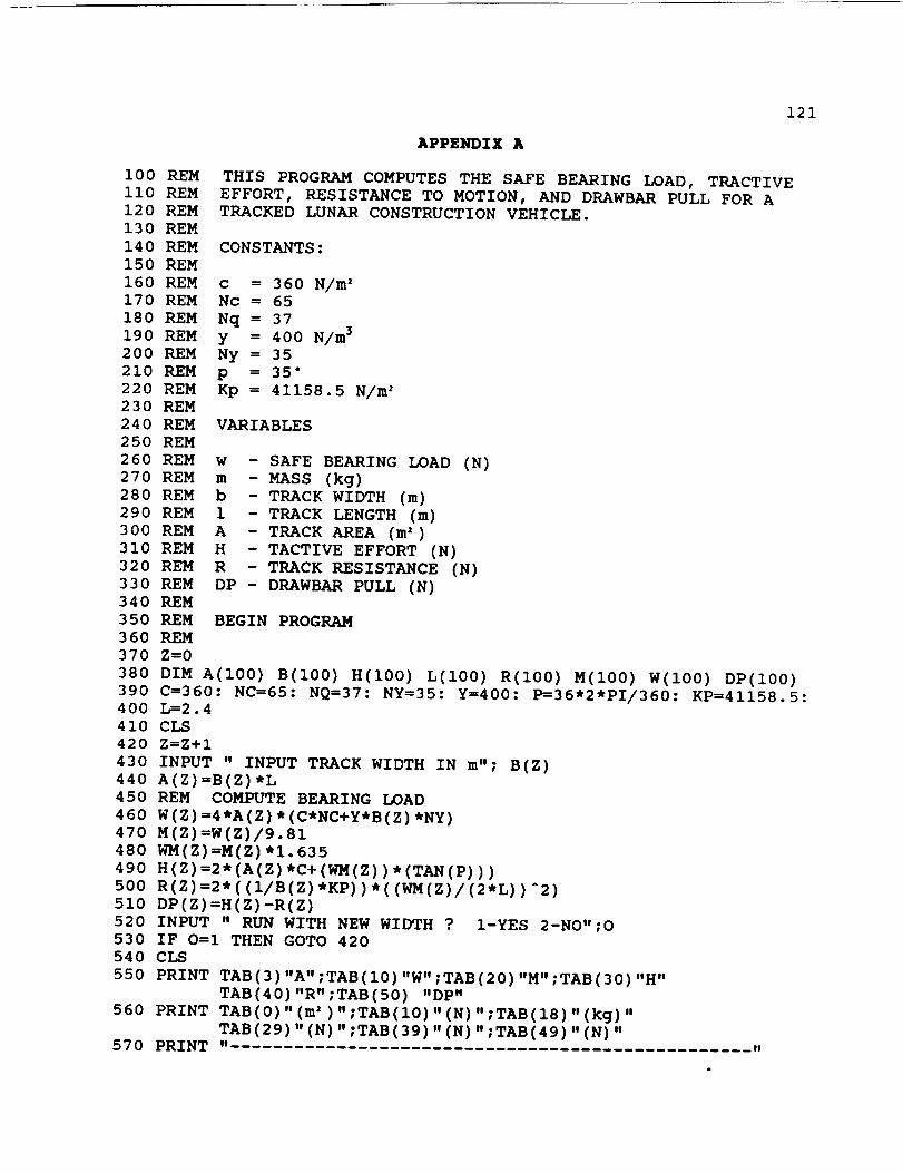
121
APPENDIX A
i00 REM
ii0 REM
120 REM
130 REM
140 REM
150 REM
160 REM
170 REM
180 REM
190 REM
20O REM
210 REM
220 REM
230 REM
240 REM
250 REM
260 REM
270 REM
280 REM
290 REM
300 REM
310 REM
32O REM
330 REM
340 REM
350 REM
360 REM
370 Z=0
THIS PROGRAM COMPUTES THE SAFE BEARING LOAD, TRACTIVE
EFFORT, RESISTANCE TO MOTION, AND DRAWBAR PULL FOR A
TRACKED LUNAR CONSTRUCTION VEHICLE.
CONSTANTS:
c = 360 N/m 2Nc = 65
Nq = 37
y = 400 N/m 3
Ny = 35
p = 35"
Kp = 41158.5 N/m 2
VARIABLES
w - SAFE BEARING LOAD (N)
m - MASS (kg)
b - TRACK WIDTH (m)
1 - TRACK LENGTH (m)
A - TRACK AREA (m')
H - TACTIVE EFFORT (N)
R - TRACK RESISTANCE (N)
DP - DRAWBAR PULL (N)
BEGIN PROGRAM
380 DIM A(100) B(100) H(100) L(100) R(100) M(100) W(IO0) DP(100)
390 C=360: NC=65: NQ=37: NY=35: Y=400: P=36*2*PI/360: KP=41158.5:
400 L=2.4
410 CLS
420 Z=Z+I
430 INPUT " INPUT TRACK WIDTH IN m"; B(Z)
440 A(Z)=B(Z)*L
450 REM COMPUTE BEARING LOAD
460 W(Z)=4*A(Z)*(C*NC+Y*B(Z) *NY)
4vo M(Z)=W(Z)/9.81480 WM(Z) =M(Z) *I. 635
490 H(Z)=2*(A(Z)*C+(WM(Z))*(TAN(P)))
500 R(Z) =2" ((I/B(Z) *KP) ) *((WM(Z)/(2*L) ) A2)
510 DP(Z) =H(Z)-R(Z)
520 INPUT " RUN WITH NEW WIDTH ? 1-YES 2-NO";O
530 IF O =I THEN GOTO 420
540 CLS
550 PRINT TAB(3) "A" ;TAB(10) "W" ;TAB(20) "M" ;TAB(30) "H"
TAB(40) "R" ;TAB(50) "DP"
560 PRINT TAB(0) "(m' ) ";TAB(10) "(N) ";TAB(18) "(kg) "
TAB (29)" (N)" ;TAB (39)" (N) ";TAB (49) " (N) "570 PRINT " "

122
58O590
600610620630640650660670680690700710720730740
750
760770780
7908O0
FOR N=I TO ZPRINT TAB(0)A(N) ;TAB(7)WM(N) ;TAB(17)M(N) ;TAB(27)H(N) ;
TAB(37)R(N) ;TAB(47) DP(N) ;NEXT NPRINT ;PRINT ; PRINT ;PRINT; PRINTINPUT " INPUT SPECIFIC MASS FOR TRACK ? 1-YES 2-NO" ;OIF 0-2 THEN ENDU=U+IINPUT " INPUT TRACK WIDTH AND MASS ";B(U),M(U)A(U) =B(U) *Lw(u)-M(u) ,i. 63sH(U) =2* (A(U) *C+W (U) *TAN(P) ) )
R (U) =2" ( (I/B (U) *KP) )*((W(U)) / (2*L)) "2)
DP(U)=(H(U)-R(U) )
INPUT " INPUT ANOTHER WIDTH AND MASS ? 1-YES 2-NO";O
IF 0=I THEN GOTO 640
CLS
PRINT TAB (3)"A" ;TAB(10)"W" ;TAB(20)"M" ;TAB (30)"H"
TAB(40)"R";TAB(50) "DP"
PRINT TAB(0) "(m' ) ";TAB (i0) "(N) ";TAB(18) " (kg) "
TAB (29) " (N) ";TAB (39) " (N) ";TAB (49) " (N) "PRINT " ........... "
FOR N=I TO U
PRINT TAB(0)A(N) ;TAB(7)WM(N) ;TAB(17)M(N) ;TAB(27)H(N) ;
TAB(37)R(N) ;TAB(47)DP(N) ;
NEXT
END
END
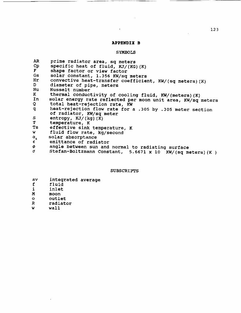
123
ARcpF
Gs
Hr
D
Nu
K
In
Q
q
S
T
Ts
w
(1 s
a
_,PPENDIX B
SYMBOLS
prime radiator area, sq meters
specific heat of fluid, KJ/(KG)(K)
shape factor or view factor
solar constant, 1.356 KW/sq meters
convective heat-transfer coefficient, KW/(sq meters) (K)
diameter of pipe, meters
Nusselt number
thermal conductivity of cooling fluid, KW/(meters) (K)
solar energy rate reflected per moon unit area, KW/sq meters
total heat-rejection rate, KW
heat-rejection flow rate for a .305 by .305 meter section
of radiator, KW/sq meter
entropy, KJ/(kg)(K)
temperature, K
effective sink temperature, K
fluid flow rate, kg/second
solar absorptance
emittance of radiator
angle between sun and normal to radiating surface
Stefan-Boltzmann Constant, 5.6671 x i0 KW/(sq meters) (K)
av
f
i
M
o
R
w
integrated average
fluid
inlet
moon
outlet
radiator
wall
SUBSCRIPTS

ORIGINAL P_ q,3
APPENDIX C
124
2@3@
45t,1
120
L30
140
160
.L70
180
190
200
210
220
230
240
250
26@
270
280
290
300
310
3e_
330
34_,
350
36_
,370
380
390
40121
410
420
430
440
450
460
47e
480
490
50el
510
5eo53e
540 '
550 '
560 '
570
580
581
590
COOL
D
W
CP
VIS
PR
K
HR
RE
NU
TFI
TFG
COMPUTER PR'C,C}RAM TO SIZE RADIATOR
LUNAR CONSTRUCT[0N UT[I_LTY Vf-'I41CLF
GROUP 2
Ic'RI]E_}'_AM Ml:liqE ." _'-tl_:[)ZA TIE
DESCL']:P:'-I ; ON C)F VARkHBLE S)
'TM
'ANGLE
'GS
'SBC
'PCELL
'NCELL
PMTR
NMTR
N
Q
A
E
TS
TWI
TWO
TWAV
AREA
: NAME OF:" THE COOLING FLUID BEING ANALYZED
: DIAMEFER OF I:'IgE USED TO CARRr COOL,[NG F'LUID (METERS): MASS FLOW RATE OF COC)LING FLUID (KG/SEC)
: SPECIFIC HEAl OF THE COOLING F'LUID (KJ/(KG) (K))
: DYNAMIC VISCOSITY OF COOLING FLUID (<N) (SEC)/SQ METERS)
: PRANTI_ NUMBER OF CO01_ING FLUID
: THERMAL CONDUCt IVIIY OF COOLING _:LUID (KW/(METERS) (K) >
: CONVECTIVE HEAT TRANSFER COEFFICIENT (KW/(SO METERS)(K)): REYNOLDS NUMBER
: NUSSEI_ r NUMBER
: TEMPERATURE OF COOLING FLUID AT THE RADIATOR Ir_LET (K)
: TEMPERATURE OF COOLING I--LUID AT THE RADIAFOR OUTLET (K)
DELTATF: TEMPERATURE DIFFERENCE OF COOLING FLUID AT THE RADIATOR INLET
AND OUTLET (K)
: LUNAR SURFACE TEMPERATURE (K)
: ANGLE BETWEEN SUN AND NORMAL FO RADIATOR SURFACE (DEGREES)
: SOLAR CONSTANT (KW/SQ METERS)
: STEPHAN-BOLTZMANN CONSTANT (KW/(SQ METERS) (K_4))
: POWER OUTPUT OF THE FUEL CELL (KW)
: EFFICIENCY OF THE FUEL CELL
: POWER OUTPUT OF EACH MOTOR (KW)
: EFFICIENCY OF THE MOTOR
: NUMBER OF MOTORS USED
: TOTAL HEAT REJECTION FLOW RATE (KW)
: SOLAR ABSORPTANCE
: EMITTANCE OF RADIATOR
: EFFECTIVE SINK TEMPERATURE (K)
: INLET RADIATOR WALL TEMPERATURE (K)
: OUTLET RADIATOR WALL TEMPERATURE (K)
: RADIATOR AVERAGE WALL TEMPERATURE (K)
: PRIME RADIATOR AREA (SG METERS)
SUBROUTINES
8OSUB 55e 'INPUT VALUES
GOSUB 760 'RATE OF HEAT REJECTION
GOSUB 810 'TEMPERATURE OF COOLING FLUID AT THE RADIATOR OUTLET
GGSUB 870 'EFFECTIVE SINK TEMPERATURE
GOSUB 940 'CONVECTIVE HEAT TRANSFER COEFFICIENT
GOSUB 1170 'RADIATOR WALL TEMPERATURES
GOSUB 1480 'RADIATOR AVERAGE WALL TEMPERATURE
GOSUB 1580 'PRIME RADIATOR AREA
GOSUB 1630 'PROGRAM OUTPUT
END
IN_'UT VALUES
CLS
INPUT "COOLING FLUID BEING TESTED ";COOLS
INPUT "OPERATING CONDITION OF LCUV ";OPER$
INPUT "DIAMETER OF PIPE USED TO CARRY COOLING FLUID (METERS) =";D

ORIGINAL PAGE iS
OF POOR QUALITY
125
610
620
630
640
650
660
670
688
698
780
710
720
730
240
750
760
7 '70
780
790
800
810 '
820 ,
830
840
850
860 '
870 '
888 '
89_
900
910
920
930
940
950
968
970
980
990
INPUT "MASS FLOW RATE OF THE COOLING FLUID (KG/SEC) =";W
INPUT "SPECIFIC HEAT OF THE COOLING FLUID (KJ/(KG) (K))";CF'
[IqPUT "TI:Mt:'ERAI'URI:" OF COOLING FLUID AT THE RADIATOR OUTLET (K) =";TI--OINPUT "SOLAR ABSORPTANCE =";A
£NPUF "EMITTANCE OF I_'ADIAFOR =";E
INPUT "LUNAR SURFACE TEMPERATURE (K) =";TM
[I_PUF "AI'_GI_E BFrwHEN Su,,_ AI'_D N(]RMAL ro RAD£AFOR SURFACE (DEGREES) :";Ar_GI_E
INPUT "SOLAR CONSIANI (KW/SQ METERS) =";GS
INPUT "STEPHAM-BOLFZMANN (]ONSrAI4T (KW/ (SO MFFERS) (K_4)) =" ;SBC
INPUT "POWER OUTPUT OF THE FUEL CELL (KW) =";PCELL
INPUT "EFFICIENCY OF THE FUEl_ CELl_ =";NCELL
INPUT "POWER OF EACH MOTOR (KW) =";PMTR
INPUF "EFFICIENCY OF [HE MOTOR =";NMTR
INPUT "NUMBER OF MOTORS USED =";N
RETURN
' RATE OF HEAT REJECTION
Q=PCELL* (1/NCELL-1) +N*PMTR* (1/NMTR-1)
RETURNI
TEMPERATURE OF COOLING FLUID AT THE RADIATOR OUTLET
DELTATF=Q/(W*CP)
TFI=TFO+DELTATF
RETURN
EFFECTIVE SINK TEMPERATURE
PI=3.14159
ANGLE=ANOLEm(PI/180)
TS=(TM*4/2+(GS/(2*SBC))*(A/E)*COS(ANOLE))^.25
RETURN9
' CONVECTIVE HEAT TRANSFER COEFFICIENTI
MEANTF=(TFO+TFI)/2
CLS
PRINT "TEMPERATURE OF COOLING FLUID AT RADIATOR INLET =" TFI "K"
1090
1100
1110
1120
1130
1140
1150
1160 '
1170 '
1180 '
1000 PRINT
1010 PRINT "TEMPERATURE OF COOLING FLUID AT RADIATOR OUTLET -" TFO "K"
1020 PRINT
1030 PRINT "MEAN TEMPERATURE OF COOLING FLUID =" MEANTF "K"
1040 PRINT
1050 PRINT "THE PROPERTIES REQUIRED TO CALCULATE THE CONVECTIVE HEAT TRANSFER"
1060 PRINT "COEFFICIENT SHOULD BE EVALUATED AT THE MEAN TEMPERATURE OF THE"
1870 PRINT "COOLING FLUID."
1080 PRINT
INPUT "VISCOSITY OF THE COOLING FLUID ((N) (SEC)/SQ METERS> =";VIS
INPUT "PRANTL NUMBER OF COOLING FLUID =";PR
INPUT "THERMAL CONDUCTIVITY OF COOLING FLUID (KW/(METERS) (K)) =";KRE=(4*W)/(PI*D*VIS)
NU=.@23*(RE^.8)*(PR_.4)
HR=(NU*K)/D
RETURN
RADIATOR WALL TEMPERATURES
1190 TWI=TFI
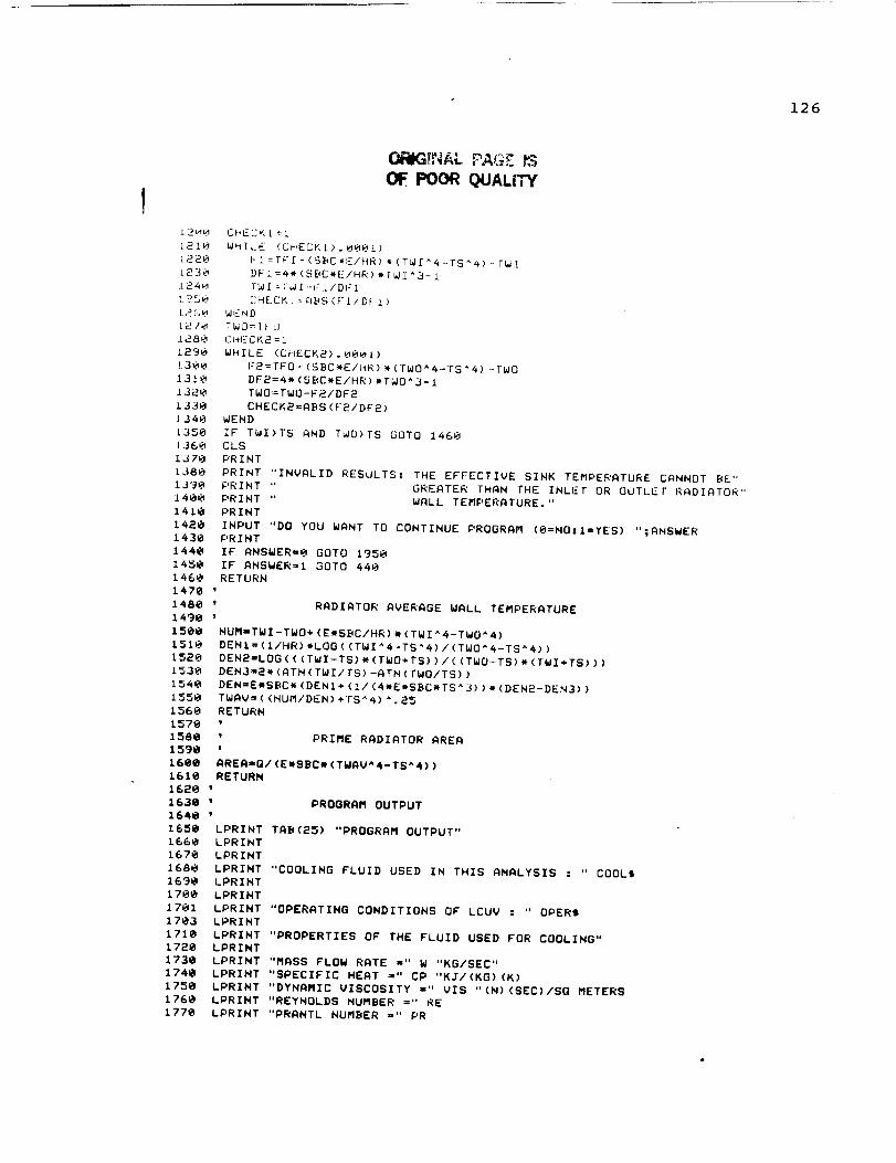
126
O_@GLN AL PAGZ
OF. POOR QUALITY
12___ CHECK1=1
121_ WHILE (CHECK1>. 0001)
1.220 FI=TF[-<S[_C,F/HR)* (TWf_4-TS_a)--TWI
L_30 DFI=4* (SBC*E/HR)*TWI^3-1
1_4H [W[ = FWf-FL/DFI
l _250 [_HE.CY,L=:A_._S(F 1/DF I )
L260 WIEND
!.270 7WO=l_ 0
].280 CPiI:CK2 = l
1290 WHILE (CHECK2) . _001)
L300 F2=FFO-(SBC*E/14R)*(FWO ^4-TS ^4) .-FWO
1310 DF2=4*(SBC*E/HR)*TWO^3-1
£ 320 [WO=TWO-F__/DF2
1330 CHECK2=ABS (F2/DF2)
.1340 WEND
[350 IF TWI>TS AND TWO>TS GOTO 1460
1360 CLS
1,370 PRINT
1380 PRINT "INVALID RESULTS: THE EFFECTIVE SINK TEMPERATURE CANNOT BE"
1390 PRINT " GREATER FHAN THE INLI-T OR OUTL.EF RADIATOR"
1400 PRINT " WALL TEMPERATURE."
1410 PRINT
1420 INPUT "DO YOU WANT TO CONTINUE PROGRAM (O=NO:I=YES) ";ANSWER
1430 PRINT
1440 IF ANSWER=O GOTO 1950
1450 IF ANSWER=I GOTO 440
1468 RETURN
1470 '
1480 ' RADIATOR AVERAGE WALL TEMPERATURE
1490 '
1500 NUM=TWI-TWO+ <E*SBC/HR) * (TWI ^4-TWO_ 4)
1510 DEN1= (I/HR) *LOG ( (TWI ^4-TS'4) / (TWO'4-TS'4))
1520 DEN2=LOG ( ((TWI-TS) * (TWO+TS)) / ((TWO-TS) * (TWI+TS)) )
1530 DEN3=2*(ATN(TWI/TS)-ATN(rWO/TS))
1540 DEN=E*SBC* (DENI+ (i / (4*E*SBC*TS^ 3) ) * (DEN2-DEN3))
1550 TWAV= ((MUM/DEN) +TS^4) _. 25
1560 RETURN
1570 '
1580 ' PRIME RADIATOR AREA
1590 '
1600 AREA=Q/(E*SBC* (TWAV"4-TS^4))
1610 RETURN
1620 '
1630 ' PROGRAM OUTPUT
1640 '
1650 LPRINT TAB(25) "PROGRAM OUTPUT"
1660 LPRINT
1670 LPRINT
1680 LPRINT "COOLING FLUID USED IN THIS ANALYSIS : " COOLS
1690 LPRINT
1700 LPRINT
1701 LPRINT "OPERATINO CONDITIONS OF LCUV : " OPER$
1703 LPRIMT
1710 LPRINT "PROPERTIES OF THE FLUID USED FOR COOLING"
1720 LPRIMT
1730 LPRINT "MASS FLOW RATE =" W "KG/SEC"
1740 LPRINT "SPECIFIC HEAT =" CP "KJ/(KG)(K)
1750 LPRINT "DYNAMIC VISCOSITY =" VIS "(N) <SEC)/SO METERS
1760 LPRINT "REYNOLDS NUMBER =" RE
1770 LPRINT "PRANTL NUMBER =" PR
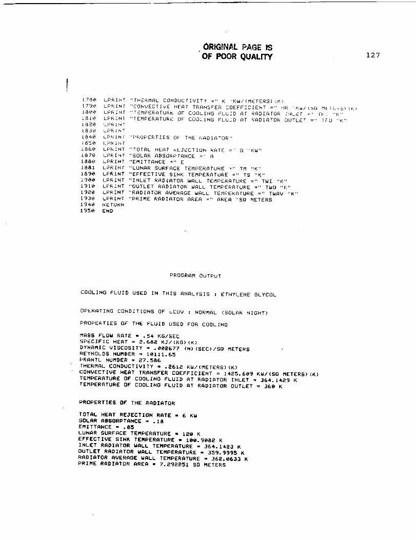
ORIGINAL PAGE IS
OF POOR QUALITY 127
L780 LPRfMT "[HERMAL CONDUCTIVITY =" K "KW/(MEFERS)(K)
179_ LPRINT "CONVECTIVE HEAT TRANSFER COEFFICIENT =" HR "r,WI(SQ r'IEIE_<S)(K)
J.SL_O LPR£NT "TEMPERATURE OF COOLING FLUID AF RADIATOR _NLFr =" ri-[ "K"
1810 LPRINT "TEMPERATURE OF" COOLING FLUID AI RADIATOR OUTLET =" TFO "K"
1.8P_0 LI:'R_N /
L830 LPRINT
1840 LPRINT "PROPERTIES OF THE _'<ADIATOR"
i850 I_I:'F(I r_F
].860 LPRINT "TOIAL HEAT _(LJECTION RATE =" Q "KW"
1870 LPRINT "SOLAR ABSORPTANCE =" A
1880 LPRINT "EMITTANCE =" E
1.881 LPRIN[ "LUNAR SURFACE TEMI:,ERATURE =" TM "K"
1890 LPRINT "EFFECTIVE SINK TEMPERATURE =" TS "K"
1900 LPRINT "INLET RADIATOR WALL TEi_IPERAFURE =" TWI "K"
1910 LPRINT "OUTLET RADIATOR WALL TEMPERATURE =" TWO "K"
1920 LPRINT "RADIATOR AVERAGE WALL FEMI:'ERATURE =" TWAV "K"
1930 LPRINT "PRIME RADIATOR AREA =" AREA "SO METERS
1940 RE TURN
1950 END
PROGRAM OUTPUT
COOLING FLUID USED IN THIS ANALYSIS : ETHYLENE GLYCOL
OPERATING CONDITIONS OF LCUV : NORMAL (SOLAR NIGHT)
PROPERTIES OF THE FLUID USED FOR COOLING
MASS FLOW RATE = .54 KG/SEC
SPECIFIC HEAT = 2.682 KJ/(KG) (K)
DYNAMIC VISCOSITY = ._@2677 (N) (SEC)/SQ METERS
REYNOLDS NUMBER = 10111.65
PRANTL NUMBER = 27.586
[HERMAL CONDUCTIVITY = .e612 KW/(METERS) (K)
CONVECTIVE HEAT TRANSFER COEFFICIENT = 14_5.6_9 KW/(SO METERS) (K)
TEMPERATURE OF COOLING FLUID AT RADIATOR INLET = 364.1429 K
TEMPERATURE OF COOLING FLUID AT RADIATOR OUTLET = 36@ K
PROPERTIES OF THE RADIATOR
TOTAL HEAT REJECTION RATE - 6 KW
SOLAR ABSORPTANCE = .18
EMITTANCE - .85
LUNAR SURFACE TEMPERATURE = 120 K
EFFECTIVE SINK TEMPERATURE = [email protected]@8e K
INLET RADIATOR WALL TEMPERATURE = 364.1423 K
OUTLET RADIATOR WALL TEMPERATURE = 359.9995 K
RADIATOR AVERAGE WALL TEMPERATURE = 362.0633 K
PRIME RADIATOR AREA = 7. ege251SQ METERS

'NAL wA,=E
PROGRAM [)UTPL_ P
t.;L3L31_[_',IG i-I_u_ID USED IN TH,['S ANAI_YSES : ETI,IYI.I-'_,IE GI_YCL]I_
128
CIJEi_ATING _.C!qNDIT IONS [IF _ CL)b' : MAXIFIIUM (SOLAR NOON)
,:'l;,t]l:'liF(l _[:]S Ul:: rt#l[ i-Lt_ll]D iJ',._l:(D Frail:( bOLtt__NG
MASS FLOW RATE = .54 F,G/SEC
51:'EC_FIC HEAT = 2.682 KJ/(KG)(I<)
DYNAMIC VISCOSITY = .002575 (N) (SEC)/SQ METERS
REYNOLDS NUMBER = 10512. 19
PRANTL NUMBER = 26.59i
£HERMAL CONDUCTIVITY = .2614 KW/ (MIsTERS) (K)
CONVECTIVE HEAT TRANSFER COEFFICIENT = 1450.269 KW/(SQ METERS)(K)
TEMPERATURE OF COOLING FLUID AT RADIATOR INLET = 368.2857 Ix,
TEMPERATURE OF COOLING FLUID AT RADIATOR OUTLET = 360 K
PROPERTIES OF THE RADIATOR
TOTAL HEAT REJECTION RATE = 12 KW
SOLAR ABSORPTANCE = .18
EMITTANCE = .85
LUNAR SURFACE TEMPERATURE = 336.1 K
EFFECTIVE SINK TEMPERA rURE = 282.6253 K
INLET RADIATOR WALL TEMPERATURE = 368.2853 K
OUTLET RADIATOR WALL TEMPERATURE = 359.9996 K
RADIATOR AVERAGE WALL TEMPERATURE = 364.0676 K
PRIME RADIATOR AREA = 22.26659 SQ METERS
129
14.0
I •
•
,
$
•
•
•
•
@
I0.
ii.
12.
13.
REFERENCES
Minnick, Elbert, C., Pyramidal Truss Core Panel Compared to
Corruqated Core (Navtruss} Panel, For Dr. R.L. Ash, MEM 435
Senior Seminar, October 25, 1988.
Goetzel, Claus, G., Rittenhouse, John, B., Singletary, John,
B., Space Materials Handbook, Addison-Weseley Publishing
Company Inc., Reading, Massachusetts, pp.425-442, pp.519-
532.
Draper, Charles, F., Radiation Shielding for a Lunar Base
Modul@, For Dr. R.L. Ash, MEM 435 Senior Seminar, October
25, 1988.
Everhart, John, L., Titanium and Titanium Alloys, Reinhold
Publishing Corp., New York, New York, p. 13.
The Aluminum Association, Aluminum Construction Manual:
Speci$ications for Aluminum Structures, The Aluminum
Association, New York, New York, Third Edition, 1970, p.53.
Shigley, Joseph, E., Mitchell, Larry, D., Mechanical
Engineerinq Desiqn, McGraw Hill Publishing Co., New York,
New York, 4th Edition, 1983, p.800.
M.G. Bekker. Off the Road I_)Go_otion, Research and
DeveloPment in Terramechanics. Edited by Ann Arbur.
University of Michigan Press, 1961.
H.T. McAdams, P.A. Reese, and G.M. Lewandowski, prepared by
Cornell Aeronautical Laboratory, Inc. Traffacicability and
Visibility Analysis of the Lunar Surface• NASA contract
report CR-1881, July 1971.
M.G. Becker Theory of Land Locomotion _ The Mechanics
of V_hicle Mobility). Edited by Ann Arbur, University
of Michigan Press, 1960
G. Davis, M. Hooker, T. Nordtredt, C. Bryant, N. Lebigot.
NASA/USRA Advanced summe_ Desiqn Report. August 1988.
Executive Summary Report Lockheed Missile and Space Company.
Desiun. Fabrication and Delivery of an Improved Sinqle Elastic
Loop Mobility system (ELMS). 1972.
Smith and William• princiDles of Materials Science and
E_Lqili_Ig. McGraw Hill Book Company, 1984.
Goetael,Claus,G. Rittenhouse, John,B.,Singletary,John, B.
Space Materials Handbook, Addison-Weseley Publishing Co.
Inc.,Reading Massachusetts•

14.
15.
16.
22.
23.
24.
25.
26.
27.
28.
29.
30.
31.
130
Greenwood,Donald G.,principles of Dynamics,PrenticeHall,1988.
" Macpherson Strut Suspension",Motor Age ,Semptember 1982
Fogiel,M.,Handbook of mathematical,Scientific,
and Enaineering Formulas, Tables, Functions,Graphs,Transforms
Parrish, M. A., "Fuel Cells-A Survey," Materials in
Enqineerinq, Scientific and Technology Press, Surrey,
England, Vol. 2, No. 2, Dec. 1980, pp. 68-72.
Angrist, Stanley W., Direct _ne_gy Conversion, Allyn and
Bacon, Inc., Boston, Massachusetts, Fourth edition, 1982.
Schubert, F. H., Hoberecht, M. A., Le, M., "Alkaline Water
Electrolysis Technology for Space Station Regenerative
Fuel Cell Energy Storage," Proceedings of the 21st
Intersociety Energy Conversion Engineering Conference,
American Chemical Society, Washington, D. C., August 1986,
pp. 1617-1626.
McAdams, H.T., Reese, P. A., Lewandowski, G. M.,
Trafficabilitv and Visibility Analysis of the Lunar Surface,
NASA Contract Report NASA Cr-1881, Correll Aeronautical
Laboratory, Inc., Buffalo, New York, July 1971, pp. 63-75.
Le, Mike, Engineer,
conversation,
Febuary 17, 1989.
Johnson Space Center, Phone
McDougall, Angus, Fuel Cells, Halstead Press, New York,
New York, First edition, 1976.
Kenyo, T., "Chromium-Doped Raney Nickel Catalyst for
Hydrogen Electrodes in Alkaline Fuel Cells,"
the Electrochemical Society, Electrochemical Society, Inc.,
Manchester, New Hampshire, Vol. 132, No. 2, Febuary 1985,
pp. 383-386.
Bayazitoglu, Y.,Smith, G., Curl, R., Hyd;oaen Eneruv Part B,
Edited by T. Nejat Veziroglu, Plenum Press, New York,
New York, 1974.
Bufkin, A.L., T.O. Tri, and T.C. Trevino. 1988. EVA
Concerns for a Future Lunar Base. Dunar Bases & Space
Activities in the 21st Century. Paper no. ibs-88-214
Electro-Craft Corporation. 1980. DC Motors. Speed
Controls. $ervo Systems. Fifth edition. Hopkins,
Minnesota: Electro-Craft Corporation

32.
35.
36.
131
Schuring,D.J., H.T.McAdams, P.A. Reese, and G.M.
Lewandowski. 1971. Trafficability and Visibility
Analysis of the Lunar Surface. NASA CR-1881.
D.C.Washington
Pacific Scientific Motor Co. DC motor catalog. 1987.
Phone conversation with Dr. Richard K. Barton,
Electro-Mechanical Engineer, General Electric
Lake Road, Eire, PA. 16531
Senior
Co., East
Dallas, Thomas, Diaguila, Anthony J., Saltsman, James F.,
Desian Studies on the Effects of Orientation, Lunation, and
Location on the Performance of _unar Radiators, Lewis
ResearchCenter, Cleveland, Ohio, March 1971.
Desiqn Criteria for Controllinq Stress Corrosion Crackinq,
Prepared by Materials and Process Laboratory,
George C. Marshall Space Flight Center, Alabama, 1977.
37.
38.
41.
42.
43.
44.
ASHRAE Handbook 1985 Fundamentals, American Society of
Heating,
Refrigerating and Air-Conditioning Engineers, Inc., Atlanta,
Georgia, 1985.
Incropera, Frank P., Dewitt, David P., Fundamentals of Heat
and Mass Transfer, John Wiley & Sons Inc., New York, New
York, Second edition, 1985.
Skvlab Extravehicular Mobility Unit, NASA Report s-531.
G.R. Evans and W.E. Price, The Effects of Hiah Energy
Radiation in Infare4 0ptic_l Materials, SB-61-25, Lockneed
Missiles and Space Company, Sunnyvale, California, May 1961.
F.V. Tooley, Handbook Of Glass Manufacture, Vol 2, Ogden
Publishing Company, New York, 1960.
G. Artutunian and F.C. Seppi, The Effects of Ionizina
Radation UDOn Transparent Materials, Report RR-I, Ordnance
Tank-Automotive Command, Detroit. Arsenal, Centerline
Michigan, October 1959.
T.E. Lusk, "Infrared-Transmission Materials Would Be
Unaffected by Radiation in Space, "Electronic Design, p74, 62
October 1960.
C.G. Gortzel, J.B. Rittenhouse, and J.B. Singletory, ed.,
Space Materials Handbook, Lockneed Missles and Space
Company, Addison-Wesley Publishing Company, Inc. Reading,
Massachusetts, 1965.

45.
68.
132
J.P. Heppner, et.al, Project Vanguard MagneticFieldInstrumentation and Measurements, NASA TND-486, September1961.
46. E.K. Welhart & CH. Johnston, Sealinq of Manned Spacecraft,
McDonnell Aircraft Corporation, 24 September 1963.
47. Press Information", SDace Shuttle TransDortation Systems,
Rockwell Intertional Corporations, 1984.
48. H. Misko, personal conversation, 3/22/89, Corning Glass
Company.
49. D. Higgons, personal conversations, 3/24/89, PPG Industries.
50. R. Zobrowski, personal conversation, 4/4/89, OCLA
Laboratories.
51. A. Abbott, personal conversation, 4/3/89, American Flat
Glass,Inc.
52. F.H. Samonski, Jr., E.M. Tucker, "Apollo Experience Report",
Command And Service Module Environmental Control System,
Manned Spacecraft Center, NASA, Huston, Texas, May 24 1971.
53. J. Buckley, personal conversation, 3/21/89, NASA-Langley.
54. D. Powell, personal conversations, 3/1/89, EI.Du Pont De
Nemours and Company.
55. G. Graf, "Upon The Farm", _, April 1987.
56. P. Romans secretary, personal conversation, March 25, 1989
Owens Lorning Corporation.
57. "Properties, Processing, and applications of teflon TFE-Fluorocarbon Fiber", Du pont Technical Information; Fibers,
Bulletin TF-2, May 1978.
58. H. Mallory, personal conversation, March 31, 1989, EI. Du
Pont De Nemours and Company.
59. "Properties of DuPont Industrial Filament Yarns", DuDont
Fibers Technical Information, Multifiber Bulletin X-272,
July 1988.
67. Muehldorf, Eugene, I., and Richard F. Filipowsky, Space
Communication Systems. Englewood Cliffs New Jersey:
Prentice-Hall, 1965.
Krassner, George, N. and Jackson Michaels, Introduction to
Space _Qmmunication Systems. New york: McGraw, 1964.
133
69. Tomasi, Wayne, Advanced EleGtronic Communication Systems.
Englewood Cliffs New Jersey: Prentice-Hall, 1987.
70. Balakrishnan, A.V., ed., Space Communications.
McGraw, 1963.
New York:
71. Wolff, Edward, A., Antenna Analysis.
and Sons, 1975.
New York: John Wiley
72. Morris, D.J., Communications for Command and Control
Systems. Elmsford New york: Pergamon Press, 1983.
73. Brazell, J.W., Williams, W.M., et.al., Lunar Base
Construction Equipment, April 1988.
74. Mendell, W.W. ed., Lunar Bases and Space Activities of the
21st Centrury, Lunar and Planetary Institute, Houston, 1985.
75. Aardayfio, D.D., Pottinger, H.J., Computer Control of Bdrtic
Manipulators, Mechanical Enqineerinq, August 1982, [1o.40-
76. Nobbe, Thomas A., Shuttle Arm to Gain Eye, Brain, and Mnscle,
Machine Design, voi.58, April I0, 1986, pp.23-28.
77. Dooling, Dave, "Canadian Arm Aids Shuttle Program"
78. Wilson, J., Hydraulic and Electrical Actuation Systems for
Robotic Use on the Moon, Old Dominion University.
79. Lunar Base Surface Missions Operations, Lunar Base Sysyems
Study (LBSS] tas_ 4.1, Johnson Space Center NASA ontract No.
NAs9-1878 p.74.
80. Kuell, D.E., Butler G.V., Advances in the Astronautical
Sciences; Shuttle/Smacelab The _ew T_ansp_tatioD System and
its Utilization;Proceedinas of the Third Dulriaas SVmDossium,
Hanover, Germany, April 28-30, 1980.
81. Lindberg, G.M., Canadian stretches Shuttle Reach, Aerospace
America. May, 1985, pp.70-74.
82. Schwarte, R.. 1984. Performance capabilities of Laser Rmr/hlg
Sensors. Proc. ESA Workshop on Space Laser ADPlicat_ons and
TechnolQq7, 26-30 March (ESA SP-202,May 1984)
83. Forrester, P., and K.F. Hulme. 1981. Review of Laser
Rangefinders. Optical and Ouantum EleGtronics 3,
no. 13:259-293
84. Wilson, P.. 1982. Use of Powerful Lasers and Lidars for
Ranging and Positioning. OpZical and Quantum Electronics 2,
no. 3:37-39
85.
86.
134
Halliday, D., and R. Resnick. 1978. Physics Parts l&2. New
York: John Wiley & Sons
Skylab EVA Mobility Unit. NASA Document $531, 1982

V_
i-irl
Vl
_0 "I'I
mOZ
im