UNIVERSITI TEKNIKAL MALAYSIA MELAKA - eprints.utem.edu.myeprints.utem.edu.my/18297/1/Investigation...
24
UNIVERSITI TEKNIKAL MALAYSIA MELAKA Investigation of Short circuit forces on individual turn of transformer winding- FEM simulation This report submitted in accordance with requirement of the Universiti Teknikal Malaysia Melaka (UTeM) for the Bachelor Degree of Engineering Technology (Industrial Power) (Hons.) by LIM BOON KIAT B071210251 910104-04-5485 FACULTY OF ENGINEERING TECHNOLOGY 2015
Transcript of UNIVERSITI TEKNIKAL MALAYSIA MELAKA - eprints.utem.edu.myeprints.utem.edu.my/18297/1/Investigation...

UNIVERSITI TEKNIKAL MALAYSIA MELAKA
Investigation of Short circuit forces on individual turn of
transformer winding- FEM simulation
This report submitted in accordance with requirement of the Universiti Teknikal
Malaysia Melaka (UTeM) for the Bachelor Degree of Engineering Technology
(Industrial Power) (Hons.)
by
LIM BOON KIAT
B071210251
910104-04-5485
FACULTY OF ENGINEERING TECHNOLOGY 2015

UNIVERSITI TEKNIKAL MALAYSIA
MELAKA BORANG PENGESAHAN STATUS LAPORAN PROJEK SARJANA MUDA
TAJUK: Investigation of Short circuit forces on individual turn of transformer
winding- FEM simulation
SESI PENGAJIAN: 2014/15 Semester 1
Saya LIM BOON KIAT
mengaku membenarkan Laporan PSM ini disimpan di Perpustakaan Universiti
Teknikal Malaysia Melaka (UTeM) dengan syarat-syarat kegunaan seperti berikut:
1. Laporan PSM adalah hak milik Universiti Teknikal Malaysia Melaka dan penulis. 2. Perpustakaan Universiti Teknikal Malaysia Melaka dibenarkan membuat salinan
untuk tujuan pengajian sahaja dengan izin penulis. 3. Perpustakaan dibenarkan membuat salinan laporan PSM ini sebagai bahan
pertukaran antara institusi pengajian tinggi.
4. **Sila tandakan ( )
SULIT
TERHAD
TIDAK TERHAD
(Mengandungi maklumat yang berdarjah keselamatan
atau kepentingan Malaysia sebagaimana yang termaktub
dalam AKTA RAHSIA RASMI 1972)
(Mengandungi maklumat TERHAD yang telah ditentukan
oleh organisasi/badan di mana penyelidikan dijalankan)
_____________________________
Alamat Tetap:
KM 1169 Taman Jaya Kelemak,
78000 Alor Gajah,
Melaka.
Tarikh: ________________________
Disahkan oleh:
_____________________________
Cop Rasmi:
Tarikh: _______________________
** Jika Laporan PSM ini SULIT atau TERHAD, sila lampirkan surat daripada pihak berkuasa/organisasi
berkenaan dengan menyatakan sekali sebab dan tempoh laporan PSM ini perlu dikelaskan sebagai
SULIT atau TERHAD.

i
DECLARATION
I hereby, declared this report entitled “Investigation of short-circuit forces on
individual turn of transformer winding- FEM simulation” is the results of my own
research except as cited in references
Signature :………………………….
Name : … LIM BOON KIAT …
Date : ……11/12/2015……….
ii
APPROVAL
This report is submitted to the Faculty of Engineering Technology of UTeM as a
partial fulfillment of the requirements for the degree of Bachelor of Engineering
Technology (Industrial Power) (Hons.). The member of the supervisory is as
follow:
……………………………….
(Project Supervisor)
iii
ABSTRACT
In the rapid development of power industry, the need of power transformer
capacity is increasing and higher voltage level is used in the system. In this situation
short circuit fault easily occurs on transformer winding. When short-circuits occur
the currents in transformer turn induce excessive forces in the transformer. These
electromagnetic forces are important considerations in the design of transformer as
the design of the windings and bracing must consider the magnitude of these forces
and provide adequate strength to withstand them without significant mechanical
deformation which could result failure. The study tested the short-circuit forces on
individual turn of transformer winding is focus and the electromagnetic force due a
short circuit current are solved by Finite Element Method (FEM). These
electromagnetic forces on transformer winding are modelled by ANSYS and then
simulated by FEM.
iv
ABSTRAK
Dalam perkembangan pesat industri tenaga, kapasiti kuasa pengubah semakin
meningkat dan voltan tahap tinggi digunakan, dalam keadaan ini litar pintas mudah
berlaku pada pengubah penggulungan. Apabila litar pintas berlaku arus akan
menjana kuasa yang berlebihan di dalam pengubah. Kuasa elektromagnet ini
merupakan pertimbangan penting yg perlu diambil kira dalam reka bentuk pengubah
belitan dan perembatan. Nilai kuasa ini akan memberikan kekuatan yang mencukupi
untuk menahan ia tanpa pengubahan bentuk mekanikal yang ketara. Dalam laporan
ini daya litar pintas pada individu penggulungan pengubah akan dikaji. Selain itu
daya elektromagnet akan diselesaikan menggunakan Kaedah Unsur Terhingga
(FEM). Kuasa elektromagnet pada pengubah penggulungan dimodelkan oleh
ANSYS dan seterusnya simulasi menggunakan FEM.

v
DEDICATIONS
To my beloved parents

vi
ACKNOWLEDGMENTS
First of all, I would like to express my greatest gratitude and thanks to
Universiti Teknikal Malaysia Melaka (UTeM) for the opportunity to completely the
PSM and their kind effort to provide me with all the facilities and technical expertise
to make this report successful.
Beside that I also would like to give my greatest thank to our project
supervisor, En Zulkifli Bin Ibrahim and En Syahrul Hisham Bin Mohamad @ Abd.
Rahman in their guide and opinions for my PSM. Thank also to my friends who help
me with given many ideas and willing to share their information and knowledge with
me.
Furthermore, I would like to thank my parents of their given moral support
and always be at my side when I need them. Finally, thank to all the people who
involved direct and indirect to complete this report.

vii
TABLE OF CONTENTS
DECLARATION ................................................................................................................... i
APPROVAL .......................................................................................................................... ii
ABSTRACT ......................................................................................................................... iii
ABSTRAK ........................................................................................................................... iv
DEDICATIONS ..................................................................................................................... v
ACKNOWLEDGMENTS ................................................................................................... vi
TABLE OF CONTENTS .................................................................................................... vii
LIST OF FIGURES ............................................................................................................... x
LIST OF TABLE ................................................................................................................. xi
CHAPTER 1 .......................................................................................................................... 1
1.0 Introduction ............................................................................................................. 1
1.1 Problem statement ................................................................................................... 1
1.2 Objectives ................................................................................................................ 2
1.3 Scope ....................................................................................................................... 2
CHAPTER 2 .......................................................................................................................... 3
2.0 Introduction ............................................................................................................. 3
2.1 Core construction .................................................................................................... 3
2.2 Short-circuits current effects the transformer winding ............................................ 4
2.3 Mechanical forces effect on transformer winding during short-circuit ................... 5
2.4 Radial forces in windings ........................................................................................ 5

viii
2.5 Axial forces in windings .......................................................................................... 6
2.6 Displacement between winding ............................................................................... 7
2.7 Calculation of the electromagnetic forces ............................................................... 8
2.7.1 Calculation of radial electromagnetic forces for concentric windings............. 9
2.7.2 Calculation of axial electromagnetic forces for concentric windings ............ 10
2.8 Finite Element Method for Designing and Analysis of the transformer ............... 11
CHAPTER 3 ........................................................................................................................ 13
3.0 Introduction ........................................................................................................... 13
3.1 Project development flow ...................................................................................... 13
3.1.1 Flow chart of the research .............................................................................. 14
3.2 Literature Review .................................................................................................. 15
3.3 Software installation .............................................................................................. 15
3.4 Finite Element Method .......................................................................................... 16
3.5 Finite Element Modelling ...................................................................................... 17
3.6 Magnetic Force ...................................................................................................... 18
3.7 Step in simulate magnetic force in 2D ANSYS Maxwell ..................................... 19
CHAPTER 4 ........................................................................................................................ 24
4.0 Introduction ........................................................................................................... 24
4.1 Construction and dimension of core ...................................................................... 25
4.2 Construction and dimension of winding ............................................................... 26
4.3 Geometrical Characteristics of transformer........................................................... 27
4.4 Simulation Result from ANSYS Maxwell 2D ...................................................... 30
4.5 Magnetic B field plot ............................................................................................. 31

ix
4.6 Flux line plot ......................................................................................................... 32
4.7 B vector plot .......................................................................................................... 33
4.8 Surface force density ............................................................................................. 34
4.9 Analytical Calculation Result ................................................................................ 35
4.10 Comparison result between two methods .............................................................. 36
CHAPTER 5 ........................................................................................................................ 38
5.0 Introduction ........................................................................................................... 38
5.1 Summary of Research ........................................................................................... 38
5.2 Achievement of Research Objectives .................................................................... 39
5.3 Significance of Research ....................................................................................... 39
5.4 Problems Faced During Research ......................................................................... 40
5.5 Suggestion for Future Work .................................................................................. 40
REFERENCES ..................................................................................................................... 41

x
LIST OF FIGURES
Figure 2.1 : Type of transformer ................................................................................. 4
Figure 2.2 : Mechanical forces on transformer winding. (Jurcik, J., Gutten, M., & Korenciak, D. 2011) ..................................................................................................... 5
Figure 2.3: Typical effects of electromechanical stress on the transformer windings caused by radial forces. (Rosentino Jr, A. J. P et al, 2011). ......................................... 6
Figure 2.4 : Typical effects of electromechanical stress on the transformer windings caused by axial forces. (Rosentino Jr, A. J. P et al, 2011). .......................................... 7
Figure 2.5 : Axial forces on the winding (Ana C. De Azevedoet al ,2006) ................. 8
Figure 2.6: Cross section of a transformer concentric windings .................................. 9
Figure 2.7 : Cross section of a transformer, radial field density and axial force ....... 10
Figure 3.1 : Flow chart of research ............................................................................ 14
Figure 3.2 : ANSYS Maxwell .................................................................................... 15
Figure 3.3 : Different methods of electromagnetic analysis ...................................... 16
Figure 3.4 : Steps to be taken when using Finite Element Software ......................... 17
Figure 3.5 : Procedure to model 3 phase transformer ................................................ 18
Figure 3.6 : Sketched winding / command window ................................................... 19
Figure 3.7 : Material selection ................................................................................... 20
Figure 3.8 : Step to assign current in winding .......................................................... 20
Figure 3.9 : Steps to assign force parameter .............................................................. 21
Figure 3.10 : Create region and ballon ....................................................................... 22
Figure 3.11 : Validation check ................................................................................... 22
Figure 3.12 : Solution data ......................................................................................... 23
Figure 4.1: Three phase transformer and their winding ............................................. 24
Figure 4.2 : Core dimension ....................................................................................... 25
Figure 4.3 : Core dimension ....................................................................................... 26
Figure 4.4 : Winding dimension................................................................................. 26
Figure 4.5 : Winding Hight ........................................................................................ 27
Figure 4.6 : Geometrical Characteristics of transformer ............................................ 27
Figure 4.7 : 90MVA of 132/33KV transformer ........................................................ 28
Figure 4.8 : Dimension of winding in simulation ...................................................... 29
Figure 4.9 : Winding sketched in ANSYSS MAXWELL 2D .................................. 29
Figure 4.10 : Radial and Axial Force Simulation Result ........................................... 30
Figure 4.11 : Magnetic B field plot ............................................................................ 31
Figure 4.12 : Flux line ................................................................................................ 32
Figure 4.13 : B vector plot ......................................................................................... 33
Figure 4.14 : Surface force density ............................................................................ 34
xi
LIST OF TABLE
Table 1: Radial force analytical calculation ............................................................... 35
Table 2: Axial force analytical calculation ............................................................... 36
Table 3: Radial force comparison .............................................................................. 36
Table 4: Axial force comparison ................................................................................ 37
1
CHAPTER 1 INTRODUCTION
1.0 Introduction
Transformers are electrical devices that transform or change the voltage levels
between two circuits. It plays an important role in the power system, as it help
convert power to appropriate levels so that other components can be safely used.
These transformers are often in operation for a long time and only stop working
during power interruptions or maintenance.
Nowadays at this fast developing country, the demand of electric power is
rising sharply and it adding more and more generating capacity and interconnection
to the system. Hence, it will cause major losses when service failure and increase of
undelivered energy cost. In order to achieve trouble-free power transmission, the
failure caused by short-circuits in the transformer had to be considered.
1.1 Problem statement
In short-circuit condition, the forces occurred in winding of transformers have
to be determined. This is because electromagnetic forces occurring on the
transformer winding during short circuit condition depend on the material selection
and careful structural design. Therefore by accurately predict these forces, it aids in
choosing structural design or arrangement at the winding to mitigate the impact of
this forces in order to avoid in-service failures and reduce the undelivered energy
cost and replacement cost.
This report is concentrated on the use of Finite Element Methods (FEM) to
model transformer and demonstrate the behaviour of an individual turn during short
circuit such as magnitude of force and force direction. It is found that this method
2
provides a significant degree of accuracy which is very useful to analyse
electromagnetic forces.
1.2 Objectives
The goal that to be achieving in this research are:
1. To demonstrate the behaviour of an individual turn during short circuit by the
use of Finite Element Method (FEM)
2. To compare the analytical and numerical (FEM) calculation in normal and short
circuit conditions
3. To determine the effect of this forces on transformer
1.3 Scope
This research has the following scope:
1. To simulate the short circuit on transformer winding.
2. Plot the magnetic forces on transformer winding.

3
CHAPTER 2 LITERATURE REVIEW
2.0 Introduction
There are many literature about short-circuits on transformer winding. For
better understanding of short-circuit, many research articles of other work and also
primary and secondary source had been read and study. This chapter was going to
describe the theory and concept of the relevance information about my research
topic.
2.1 Core construction
Basically, power transformer had two designs which are core-type and shell-
type. In the core type transformer the core is surrounded by the coils are normally
with circular concentric windings, while in the shell type transformer the cores
surround the coil with sandwich windings and “pan-cake” coils. Their field pattern
depends on the overall geometry of the transformer, especially of the core and
windings and on the relative permeability of materials. Power transformer
manufacturer in North America was well-known for his use of shell-type designs
while core-type designs predominate in the UK and is the commonly used designs. In
this research or simulation the core-type design will be used to simulate short-circuit
on transformer winding.

4
Figure 2.1 : Type of transformer
Source: http://www.electricaleasy.com/2014/03/electrical-transformer-basic.html (1/3/2014)
2.2 Short-circuits current effects the transformer winding
Jurcik, J., Gutten, M., & Korenciak, D. (2011) states that short circuit and
overvoltage (transient actions) affect the power transformer and it need to be
specialise analyzed. This is because they had serious importance in design and
operation on transformer. Short-circuit in operation are mainly produced by different
line faults such as the mechanical damage of insulation, electric insulation, electric
insulation breakdown on over voltage, wrong operation and so on.
Short-circuit can be identified as serious poor condition of transformer due to
neglect because the high current produced will cause badly rising temperature that
can damage transformer insulation. The high electro-magnetic forces is the most
dangerous one as it may occur due to great destruction of transformer so the
transformer winding and its coils must be structural and stable in order to tolerate
high mechanical forces without damage .
The state of the percentage changes in short circuits voltage or impedance
depending up frequency is the geometrical winding movement refluxing and their
construction in transformer. The change of state depend on thermal and mechanical
effects of short circuits currents. For better comprehension of the relation between
transformer damage and short circuits the effect of mechanical forces on transformer
winding had to be considered.

5
2.3 Mechanical forces effect on transformer winding during short-circuit
The main cause of the pattern of forces that affect the winding is the magnetic
field that influence on current flowing conductors. In transformer, it is the field of
stray flux. When in the state of normal operation, the currents in transformer do not
exceed rating value so the forces affecting on winding was usually in low level. But
when in short-circuits conditions, the currents rating values will be double and this
forces is dangerous to the windings.
Forces that affecting the winding usually divided into two groups which is
radial forces (cross) and axial forces (longitude). These two components was
considered independently in calculating strength, as they usually produce stresses of
different kinds and can trigger different and independent modes of collapse.
Figure 2.2 : Mechanical forces on transformer winding. (Jurcik, J., Gutten, M., &
Korenciak, D. 2011)
2.4 Radial forces in windings
Radial forces are produced by the axial component of leakage flux by
Rosentino Jr. A.J.P et al (2011). This force creates different effect in the outer and
the inner winding of the transformer. In core type transformer, the tendency of the
mechanical stresses is to compress (compression stress) the inner winding and
expand (tensile stress) the outer winding. The occurrence of radial deformation in the

6
inner winding is more frequent than in the outer winding and it may occur due to two
different ways.
One of the occurrences radial deformations is the forced buckling, it occurs
when the inner winding is supported by spacers located in the axial direction to the
conductors. These occur when the stress value exceeds the material elastic limit.
While the other is known by free buckling. For this, the conductor is deformed in one
or more radial points of the coil winding.
Figure 2.3: Typical effects of electromechanical stress on the transformer windings caused
by radial forces. (Rosentino Jr, A. J. P et al, 2011).
2.5 Axial forces in windings
The axial forces are produced by the radial component of the leakage flux and
it is in control by the compressing of the windings. Under this situation, the windings
conductor can bend between the insulating spacers located radialy or leaning each

7
other. The occurrence of this latter situation is typically for the disc type windings
and generally this arrangement was used in large transformers.
Figure 2.4 : Typical effects of electromechanical stress on the transformer
windings caused by axial forces. (Rosentino Jr, A. J. P et al, 2011).
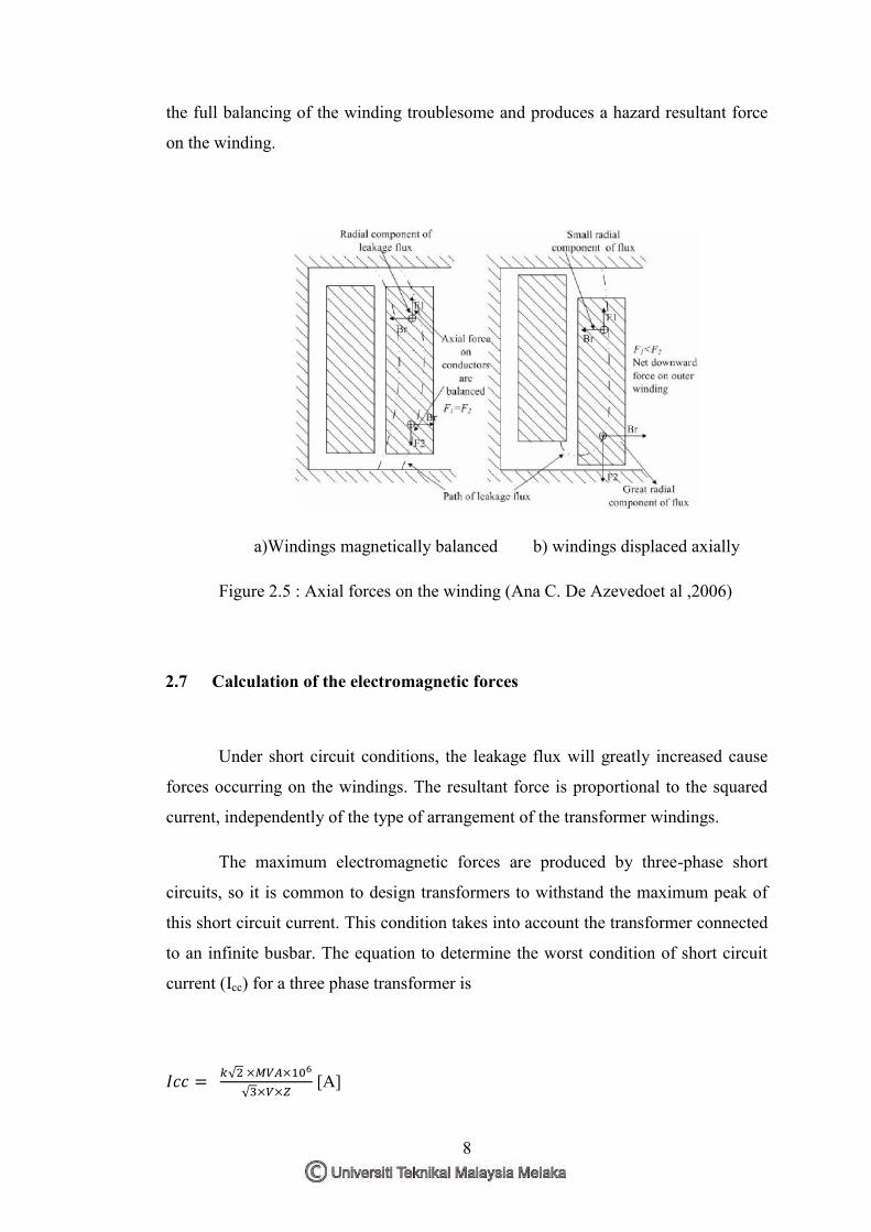
2.6 Displacement between winding
Any asymmetry between windings can produce large axial forces and produce
serious hazard for the transformer solidarity by Ana C.de Azevedo et al (2006). In
the situation where the inner and outer windings are symmetrical and balanced built
up, the leakage flux is symmetrically distributed and generating opposite axial forces
at the ends of the winding, thus generate zero resultant force.
While in high physical displacement between the inner and outer windings, it
will cause varying values for the axial forces in each half winding. This will make
8
the full balancing of the winding troublesome and produces a hazard resultant force
on the winding.
a)Windings magnetically balanced b) windings displaced axially
Figure 2.5 : Axial forces on the winding (Ana C. De Azevedoet al ,2006)
2.7 Calculation of the electromagnetic forces
Under short circuit conditions, the leakage flux will greatly increased cause
forces occurring on the windings. The resultant force is proportional to the squared
current, independently of the type of arrangement of the transformer windings.
The maximum electromagnetic forces are produced by three-phase short
circuits, so it is common to design transformers to withstand the maximum peak of
this short circuit current. This condition takes into account the transformer connected
to an infinite busbar. The equation to determine the worst condition of short circuit
current (Icc) for a three phase transformer is
[A]

9
Where: k is the factor of asymmetry;
MVA is the transformer rating power [MVA];
V is the transformer rated voltage [V];
Z is the per unit impedance of the transformer.
2.7.1 Calculation of radial electromagnetic forces for concentric
windings
The analytical calculation of radial force components in the transformer with
concentric windings can be calculated easily and accurately. The axial field density
(Ba) has its maximum in the region between the windings (leakage flux) and it is
zero in the internal and external surfaces of the inner and outer windings
respectively. Thus the force in per unit of length throughout the length of the coils
remains almost constant and can be precise calculated. Below was the cross section
for the transformer with two concentric windings.
Figure 2.6: Cross section of a transformer concentric windings
(Ana C.de Azevedo et al 2006)

10
By neglecting the flux spreading out at the end of the windings, the radial
force (Fr) due to interaction between the instantaneous-turns in each winding (ni) and
the leakage field density can calculated as below.
Where : i is the currents in transformer winding,
n is the number of turn,
h is the length of the winding and
Dm is the mean diameter of the winding.
2.7.2 Calculation of axial electromagnetic forces for concentric
windings
Below was the layout of the radial field and the axial forces in an
arrangement with asymmetrical windings. The asymmetry was due to the height of
the outer winding is shorter than the inner windings causes a huge density of radial
flux in the region where the unbalanced of ampere-turns occurs.
Figure 2.7 : Cross section of a transformer, radial field density and axial force
(Ana C.de Azevedo et al 2006)

11
The analytical calculation of the radial leakage field and axial force cannot
calculate simply as axial field calculation. Residual Ampere turns method was a
well-accepted approach used in calculate radial force, it is based on the principle that
any arrangement of concentric windings can be split into two groups having balanced
ampere turn. One produces the axial field and the other the radial field.
To calculate the axial compression force, the following parameters is
necessary to identified.
a. The effective length of path of the radial flux, heff. This differs for each
arrangement of tapings.
b. The average radial flux density (Br) , considering the average diameter of the
transformer
c. The average value of ampere turns which is equal to (1/2)a(ni), where a is the
length of tap section (or group of short-circuited turns) expressed as a fraction
of the total length of the winding.
The axial force (Fa) for a transformer with tap section in one end of the
external winding is determined as:
2.8 Finite Element Method for Designing and Analysis of the transformer
Finite Element Analysis using Finite Element Method (FEM) was used to
solve complex elasticity and structural analysis problem in civil and aeronautical
engineering by G.H.Chitaliya, S.K.Joshi (2013). This application had been enlarge to
simulation in electrical engineering to solve complex design problems and used for