UNIVERSITI PUTRA MALAYSIA COMPUTER SIMULATION OF … · baru diperkenalkan dan ia adalah antara...
25
UNIVERSITI PUTRA MALAYSIA COMPUTER SIMULATION OF SURFACE PLASMON RESONANCE FOR OPTICAL MULTI-LAYER SYSTEM MOHAMED AHMED MOHAMED SIDDIG FSAS 2000 8
Transcript of UNIVERSITI PUTRA MALAYSIA COMPUTER SIMULATION OF … · baru diperkenalkan dan ia adalah antara...
UNIVERSITI PUTRA MALAYSIA
COMPUTER SIMULATION OF SURFACE PLASMON RESONANCE FOR OPTICAL MULTI-LAYER SYSTEM
MOHAMED AHMED MOHAMED SIDDIG
FSAS 2000 8
COMPUTER SIMULATION OF SURFACE PLASMON RESONANCE FOR OPTICAL MULTI-LAYER SYSTEM
MOHAMED AHMED MOHAMED SIDDIG
MASTER OF SCIENCE UNIVERSITI PUTRA MALAYSIA
2000
COMPUTER SIMULATION OF SURFACE PLASMON RESONANCE FOR OPTICAL MULTI-LAYER SYSTEM
By
MOHAMED AHMED MOHAMED SIDDIG
Thesis Submitted in Fulfilment of the Requirements for the Degree of Master of Science in the Faculty of
Science and Environmental Studies Universiti Putra Malaysia
January 2000

Dedicated to
my
11
Parents; Brothers and Sisters.
Abstract of the thesis presented to the Senate ofUniversiti Putra Malaysia in fulfilment of the requirements of the degree of Master of Science
COMPUTER SIMULATION OF SURFACE PLASMON RESONANCE FOR OPTICAL MULTI-LAYER SYSTEM
By
MOHAMED AHMED MOHAMED SIDDIG
January 2000
Chairman: Dr. Zainul Abidin Hassan
Faculty: Science and Environmental Studies
Surface plasmon is a charge density wave on the surface of metals. The
surface plasmon resonance technique is relatively new, and it is one of the
most sensitive techniques to probe surface and interface effects. The Fresnel's
equations and Snell's law are used to compute the reflection and transmittance
of light incident on multilayers (series of N layers and N+ 1 interfaces)
between semi-infinite ambient and substrate media. The effects of multiple
reflection are taken care of by using 2 x 2 scattering matrix techniques. A plot
of a graph for reflectance and transmittance can be obtained by varying the
incident angle of a light beam at fixed frequency, or by varying the
wavelength. Various plots of reflectance and transmittance as a function of
incident angle, wavelength and interface parameters are displayed. The Visual
III
Basic 5 .0 standard edition was used in this project whereby a window-based
program with graphic user interface (QUI) was developed for the simulation of
reflectance and transmittance. After the software program was developed, it
was tested with four simulations with well-known experimental results to
ascertain the reliability of the simulations. Some of the optical experiments for
the both sections of program namely; the reflection and transmission versus
incident angle and versus wavelength were simulated. These simulations were
studied with Krestchmann's and Otto's configurations. The effect of variation
of thickness, dielectric constants, incident angles and wavelengths were
demonstrated. Based on the above simulation results, it can be concluded that
the program is general enough and it can be used to simulate reflectance and
transmittance for any materials.
iv

Abstrak tesis yang dikemukakan kepada Senat Universiti Putra Malaysia sebagai memenuhi keperluan untuk ijazah Master Sains
SIMULASI KOMPUTER UNTUK RESONAN PLASMON PERMUKAAN BAGI SISTEM BERBILANGLAPISAN
Oleh
MOHAMED AHMED MOHAMED SIDDIG
Januari 2000
Pengerusi: Dr. Zainul Abidin Hassan
Fakulti: Fakulti Sains dan Pengajian Alam Sekitar
Plasmon permukaan ialah gelombang ketumpatan cas yang wujud di
permukaan logam. Teknik resonans plasmon permukaan ialah satu teknik yang agak
baru diperkenalkan dan ia adalah antara teknik yang sangat sensitif untuk melihat
kesan permukaan dan antaramukaan. Persamaan Fresnel dan Snell digunakan untuk
mengira keterpantulan dan kehantaran cahaya yang ditujukan ke sistem berbilang
lapisan (siri N lapisan dengan N+ 1 antaramukaan) yang berada di antara media
ambien yang separuh infinit dengan media substrat. Kesan berbilang keterpantulan
diambil kira dengan menggunakan teknik serakan matriks 2x2. Plot bagi graf
keterpantulan dan kehantaran boleh diperolehi dengan mengubah sudut tuju untuk
sinar tuju pada frekuensi cahaya yang tetap ataupun dengan mengubah panjang
gelombang cahaya. Pelbagai plot keterpantulan dan kehantaran boleh diperolehi
sebagai fungsi sudut tuju, panjang gelombang dan parameter permukaan. Bahasa
pengaturcaraan Visual Basic 5.0 edisi standard telah digunakan untuk projek ini
yang mana satu aturcara berasaskan kepada sistem tetingkap dengan antaramuka
v
grafik digunakan untuk simulasi keterpantulan dan kehantaran bagi sistem berbilang
lapisan. Setelah aturcara komputer selesai, ia diuj i dengan empat simulasi yang
mana hasilnya diketahui dengan baik untuk menentukan yang hasH simulasi boleh
dipercayai . Ekperimen optik untuk kedua-dua bahagian aturcara komputer tersebut,
yakni pemantulan dan penghantaran melawan sudut perlanggaran dan jarak
gelombang, disimulasikan. Simulasi ini dibuat melalui konfugurasi Krestchmann
dan Otto. Kesan dari perubahan ketebalan, pemalar dielektrik, sudut perlanggaran
dan jarak gelombang ditunjukkan. Berdasarkan keputusan simulasi di atas, maka
bolehlah disimpulkan bahawa atucara komputer yang dihasilkan berbentuk cukup
umum untuk digunakan bagi simulasi keterpantulan dan kehantaran bagi sebarang
bahan . .
VI

ACKNOWLEDGEMENT
In the name of Allah, Most Gracious, Most Merciful. Praises and thanks belong
only to ALLAH S.W.T for giving me the strength and patience and enabling me to
complete this work.
I would like to express my deepest appreciation to my father Dr. Ahmed
Mohamed Siddig, my mother and my family, who raised, loved, guided, consulted,
educated and supported me before I became who I am now.
My sincere gratitude to Dr. Zainul Abidin Hassan, chairman of my supervisory
committee, for his excellent supervision, invaluable suggestions, helpful discussions,
beneficial advice, valuable support, endless patience and continuous encouragement
throughout this project.
Similar appreciation is extended to members of my supervisory committee,
Associate Professor Dr. Wan Mahmood Mat Yunus and Dr. Hishamuddin Zainuddin, for
their assistance, suggestions and guidance throughout this work.
I would like also to record sincere acknowledgements to my younger brother as
well as my best friend Abubaker Siddig, who has been always beside me and assisted
me to finish this project. Similar thanks to Abubaker Elshekh, Faiz Elfakih, Ahmed
Bouketir, Mohamed Fitri, Kamaruddin Mamat, Ahmed Akaak and Annan, who helped
me during my staying and studying here in Malaysia.
VIl

Finally, may Allah reward the people who helped me directly or indirectly in
finishing this work. I wish them every success in this life and hereafter under the
guidance of Allah s.w.t.
viii

I certify that an Examination Committee met on January 31, 2000, to conduct the final examination of Mohamed Ahmed Mohamed Siddig, on his Master of Science thesis entitled "Computer Simulation of Surface Plasmon Resonance for Optical Multi-layer System" in accordance with Universiti Pertanian Malaysia (Higher Degree) Act 1980 and Universiti Pertanian Malaysia (Higher Degree) Regulation 1981. The Committee recommends that the candidate be awarded the relevant degree. Members of the Examination Committee are as follows:
MOHD MAAROF MOKSIN, Ph.D. Associate Professor Faculty of Science and Environmental Studies Universiti Putra Malaysia (Chairman)
ZAINUL ABIDIN HASSAN, Ph.D. Faculty of Science and Environmental Studies Universiti Putra Malaysia (Member)
WAN MAHMOOD MAT YUNUS, Ph.D. Associate Professor Faculty of Science and Environmental Studies Universiti Putra Malaysia (Member)
HISHAMUDDIN ZAINUDDIN, Ph.D. Faculty of Science and Environmental Studies Universiti Putra Malaysia (Member)
HAZALI MOHA YIDIN, Ph.D. Professor /Deputy Dean of Graduate School
Universiti Putra Malaysia
Date: 1 6 FEB 2000
IX
This thesis was submitted to the Senate of Universiti Putra Malaysia and was accepted as fulfillment of the requirements for the degree of Master of Science.
x
KAMIS A WANG, Ph.D. Associate Professor
Dean of Graduate School Universiti Putra Malaysia
11 MAY 2000 Date:
DECLARATION
I hereby declare that the thesis is based on my original work except for quotations and citations which have been duly acknowledged. I also declare that it has not been previously or concurrently submitted for any other degree at UPM or other insti tuti ons.
MOHAMED AHMED MOHAMED SIDDIG
Date: \4· / 2./ 2. 00 D
Xl
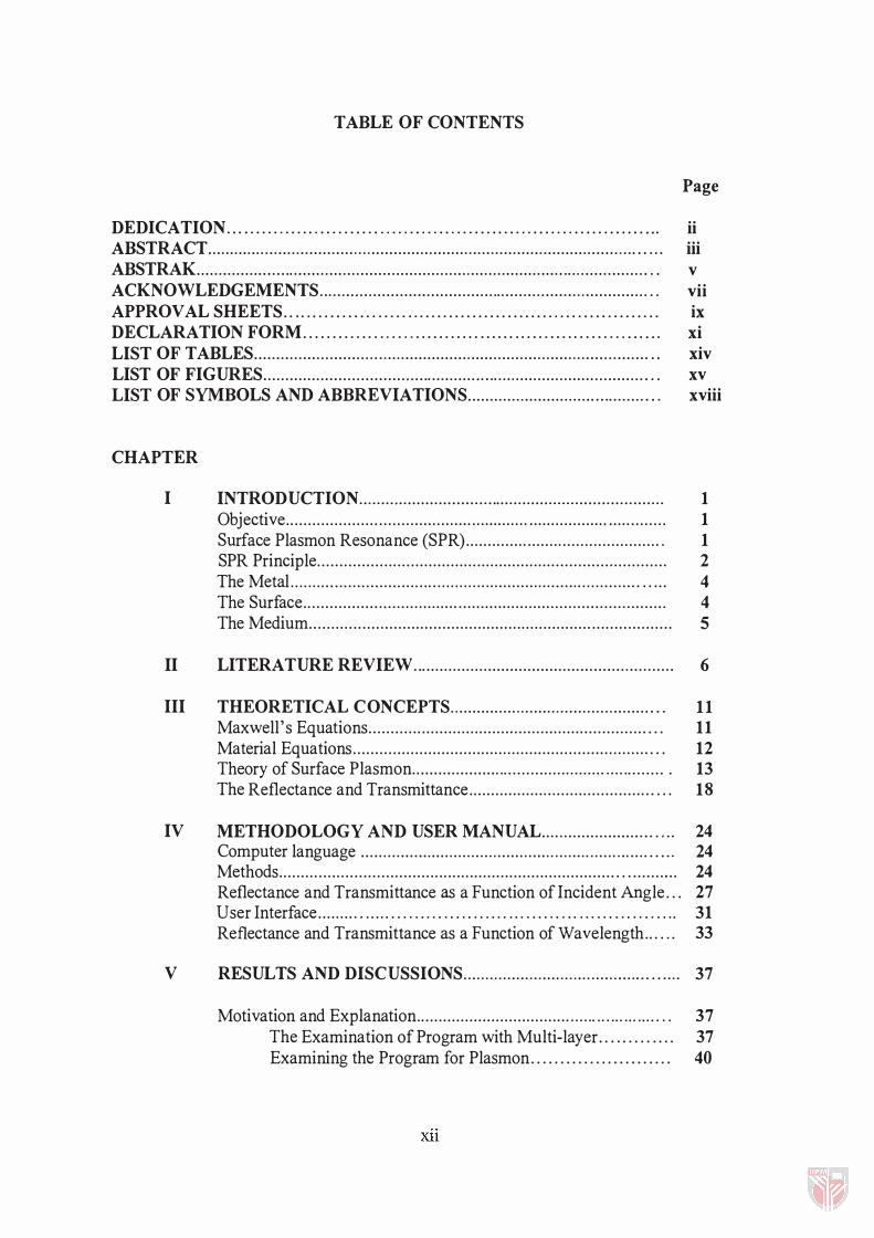
TABLE OF CONTENTS
Page
DEDICATION... .. . . . . . . . . .. . . . . . . . . . . . . . . . . . . . . . . . . . . . . . . . . . . . . . . . . . . . . . . . . . . . . . . . . ... ii ABSTRACT................................................................................................... ... iii ABSTRAK...................................................................................................... . . v ACKNOWLEDGEMENTS.......................................................................... . . vii APPROVAL SHEETS.. . . .. . . . . . . . . . . . . . . . . .. . . . . . . . . . . . . . . . . . . . . . . . . . . . . . . . . . . . . . . . . ix DECLARATION FORM.... . . . . . . .. . .. . . . .. . . . . . . . . . . ...... . . . . . . . . . . . . . . . . . . .... ... xi LIST OF T ABLES............................ ............................................................. .. xiv LIST OF FIGURES....................................................................................... . . xv LIST OF SYMBOLS AND ABBREVIATIONS......................................... . . xviii
CHAPTER
I INTRODUCTION..................................................................... 1 Objective. . . . . . . . . . . . . . . . . . . . . ..................... .................................... ........ 1 Surface Plasmon Resonance (SPR) . . . . . . . . . . . . . . ............................... 1 SPR Principle. . . . . . . . . . . . . . . . . . . . . . . . . . . . . . . . . . . . . . . . . . . . . . . . . . . . . . . . . . . . . . . . . . . . . . . . . . . . . . . 2 The Metal . . . . . . . . . . . . . . . . . . . . . . . . . . . . . . . . . . . . . . . . . . . . . . . . . . . . . . . . . . . . . . . . . . . . . . . . . . . . . . . . . . . . 4 The Surface. . . . . . . . . . . . . . . . . ................................................................. 4 The Medium. . . . . . . . . . . . . . . . . . . . . . . . . . . . . . . . . . . . . . . . . . . . . . . . . . . . . . . . . . . . . . . . . . . . . . . . . . . . . . . . . . 5
II LITERATURE REVIEW........................................................... 6
III THEORETICAL CONCEPTS.............................................. . . 11 Maxwell' s Equations. . . . . . . . . . . . . . . . . . . . . . . . . . . . . . . . . . . . . . . . . . . . . . . . . . . . . . . . . . . . . . . . . . 11 Material Equations. . . . . . . . . . . . . . . . . . . . . . . . . . . . . . . . . . . . . . . . . . . . . . . . . . . . . . . . . . . . . . . . . . . . . . 12 Theory of Surface Plasmon. . ................. ........... ........................... . 13 The Reflectance and Transmittance. . . . . . . . . . . . . . . . . . . . . . . . . . . . . . . . . . . . . . . . . . . . . 18
IV METHODOLOGY AND USER MANUAL......................... .... 24 Computer language ............... ............................ ........ ...... ... ......... , 24 Methods. . . . . . . . . . . . . . . . . . . . . . . . . . . . . . . . . . . . . . . . . . . . . . . . . . . . . . . . . . . . . . . . . . . . . . . . . . . . . . . . . . . . . . . . . 24 Reflectance and Transmittance as a Function of Incident Angle . . . 27 User Interface . . . . . . . . . . .... . . .... ... .. . .. .. ..... . .. . .... ....... .. . .. ... .. . ... 31 Reflectance and Transmittance as a Function of Wavelength. . . . .. 33
V RESULTS AND DISCUSSIONS............................. ..... ........ ...... 37
Motivation and Explanation.. . . . . . . . . . . . . . . . . . . . . . . . . . . . . . . . . . .................... . . 37 The Examination of Program with Multi-layer. . . . . . . . . . . . . 37 Examining the Program for Plasmon . . . . . . . . . . . . . . . . . . . . . . . . 40
xu
VI
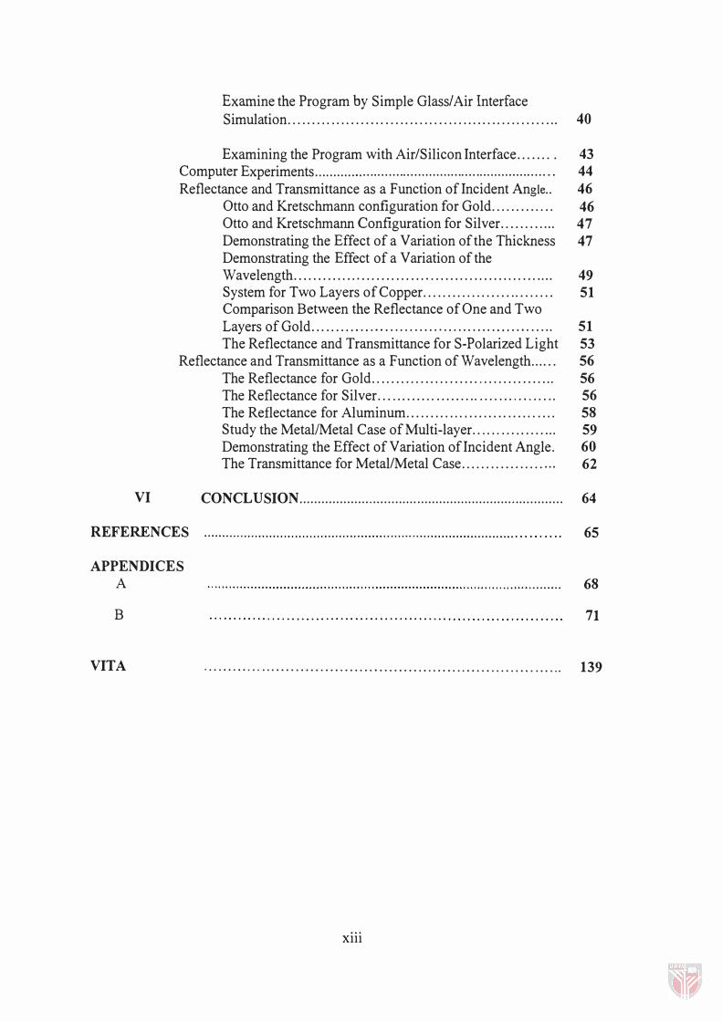
Examine the Program by Simple Glass/Air Interface Simulation. . . . . . . . . . . . . . . . . . . . . . . . . . . . . . . . . . . . . . . . . . . . . . . . . . . . . . .. 40
Examining the Program with Air/Silicon Interface....... . 43 Computer Experiments.............. ...................................... ........... . . 44 Reflectance and Transmittance as a Function of Incident Angle.. 46
Otto and Kretschmann configuration for Gold............. 46 Otto and Kretschmann Configuration for Silver............ 47 Demonstrating the Effect of a Variation of the Thickness 47 Demonstrating the Effect of a Variation of the Wavelength...................................................... 49 System for Two Layers of Copper............ ............... 51 Comparison Between the Reflectance of One and Two Layers of Gold... ...... . . . .. . . ................ . . . .. . . . . . . . . . . ... 51 The Reflectance and Transmittance for S-Polarized Light 53
Reflectance and Transmittance as a Function of Wavelength.... .. 56 The Reflectance for Gold...................................... 56 The Reflectance for Silver... . . . . . . . .. ......... .. .. ......... . .. 56 The Reflectance for Aluminum.. . . . . . . . . . . . . . . . . . . . . . . . . . . . . . 58 Study the MetallMetal Case of Multi-layer.. . .. . ... . . ....... 59 Demonstrating the Effect of Variation of Incident Angle. 60 The Transmittance for Metal/Metal Case................. ... 62
CONCLUSION . . . . . . . . . . . . . . . . . . .. .. . . . . . . . . . . . . . . . . . . . . . . . . . . . . . . . . . . . .. . . .. . . . . . . . . . 64
REFERENCES 65
APPENDICES A
B
VITA . . . . . . . . . . . . . . . . . . . . . . . . . . . . . . . . . . . . . . . . . . . . . . . . . . . . . . . . . . . . . . . . . . . . . . . . ..
Xlll
68
71
139
Table
1
2
3
LIST OF TABLES
Page
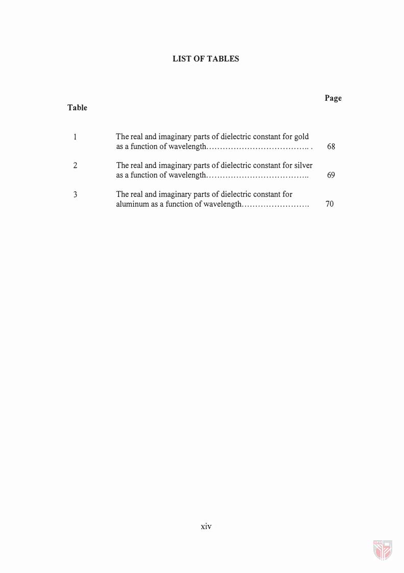
The real and imaginary parts of dielectric constant for gold as a function of wavelength........................ . ...... . . . . . . . . 68
The real and imaginary parts of dielectric constant for silver as a function of wavelength. . . . . . . . . . . . . . . . . . . . . . . . . . . . . . . . . . . . . . 69
The real and imaginary parts of dielectric constant for aluminum as a function of wavelength. ..... . . . . . ....... . .. . . .. 70
XIV

Figure
1
2
3
4
5
6
7
8
9
10
1 1
1 2
1 3
LIST OF FIGURES
Prism used to overcome the restriction of excitation of surface plasmon in metal-dielectric interface . . . . . . . . . . . . . . . . . . . . . . . . . . . . . . . . . . . . . . . . . . . . . . . . .
Graph showing the dispersion relation for surface plasmon (sp) and light. Kc is the component of light wave vector in x direction . . . . . . . .
Medium 1 is dielectric with permittivity EI> 0 and medium 2 is a plasma slab with E2 < 0 and medium3 is a dielectric with 0 < E3< E2 .. . . . ........................................................................ . . . . . . . . . .
ATR methods: (a) Krestchmann configuration, (b) Otto configuration . . . . . . . . . . . . . . . . . . . . . . . . . . . . . . . . . . . . . . . . . . . . . . . . . . . . . . . . . . . . . . . . . . . . . .
Propagation of EM fields in multi-layer thin film system with N-I layers ....................................................................... . . . . . . . . . . . . . . . . . . . . . .
An incident ray i hits interface 0- 1 at an angle 80 and refracted into medium 1 at angle BI and reflected in medium at angle Bo ........... .
Reflection and transmission of plane waves by a multi-layer structure sandwiched between semi-infinite ambient and substrate media . . . . . . . . . . . . . . . . . . . . . . . . . . . . . . . . . . . . . . . . . . . . . . . . . . . . . . . . . . . . . . . . . . . . . . . . . . . .
Flow-chart for calculation of reflection and transmission versus angle of incidence . . . . . . . . . . . . . . . . . . . . . . . . . . . . . . . . . . . . . . . . . . . . . . . . . . . . . . . . . . .
The main page of the software program . . . . . . . . . . . . . . . . . . . . . . . . . . . . . . . . . . . . . . . . . . .
The main menu page of the software program . . .. . . . . . . . ..... . ..... . .. .. ... . . .
The program interface for calculating reflectance and transmittance versus incident angle . . . . . . . . . . . . . . . . . . . . . . . . . . . . . . . . . . . . . . . . . . . . . . . . . . . . . . . . . . . . . . . . . . . .
Flow-Chart for calculation of reflection and transmission versus wavelength . . . . . . . . . . . . . . . . . . . . . . . . . . . . . . . . . . . . . . . . . . . . . . . . . . . . . . . . . . . . . . . . . . . .
The program interface for calculating reflectance and transmittance versus wavelength . . . . . . . . . . . . . . . . . . . . . . . . . . . . . . . . . . . . . . . . . . . . . . . . . . . . . . . . . . . . . . . . . . . . . , .
xv
Page
3
1 5
1 6
1 7
1 9
22
26
28
29
30
32
35
36
14
15
16
17
18
19
20
21
22
23
24
25
26
27
28
29
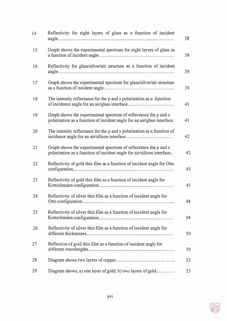
Reflectivity for eight layers of glass as a function of incident angle ........................................................................................... . . . . . . .
Graph shows the experimental spectrum for eight layers of glass as a function of incident angle ........................................ ........ .
Reflectivity for glass/silver/air structure as a function of incident angle .......................................................................... ,
Graph shows the experimental spectrum for glass/silver/air structure as a function of incident angle ............................................. .
The intensity reflectance for the p and s polarization as a function of incidence angle for an air/glass interface ............................... . .
Graph shows the experimental spectrum of reflectance the p and s polarization as a function of incident angle for an air/glass interface.
The intensity reflectance for the p and s polarization as a function of incidence angle for an air/silicon interface ............................. .
Graph shows the experimental spectrum of reflectance the p and s polarization as a function of incident angle for air/silicon interface ..
Reflectivity of gold thin film as a function of incident angle for Otto configuration ............................................................................... .
Reflectivity of gold thin film as a function of incident angle for Kretschmann configuration ............................................................ .
Reflectivity of silver thin film as a function of incident angle for Otto configuration ............................................................... ..
Reflectivity of silver thin film as a function of incident angle for Kretschmann configuration ............................................... .......... .... . ,
Reflectivity of silver thin film as a function of incident angle for different thicknesses ......................................................................... ,
Reflection of gold thin film as a function of incident angle for different wavelengths ................................................................... . . . .. .
Diagram shows two layers of copper. ................................ .... ..
Diagram shows, a) one layer of gold; b) two layers of gold ...... ..... .
XVi
38
38
39
39
41
41
42
42
45
45
48
48
50
50
52
53
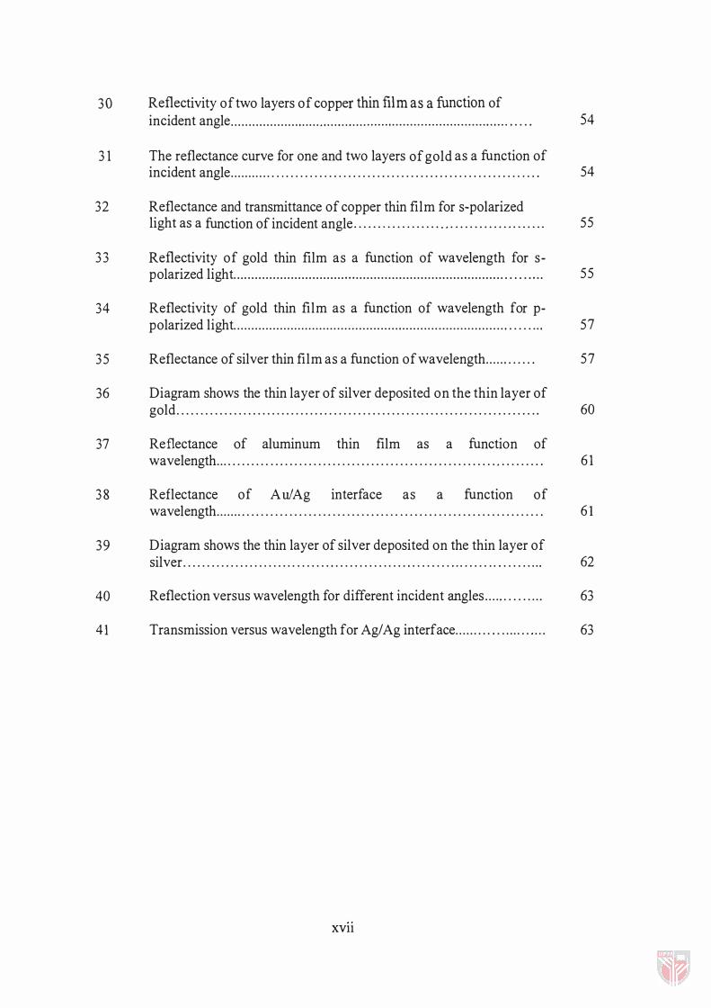
30 Reflectivity of two layers of copper thin film as a function of incident angle . . . . . . . . . . . . . . . . . . . . . . . . ... . . . . . . . . . . . . . . . . . . . . . . . . . . . . . . . . . . . . . . . . . . . . . . . . . . . . . . . 54
31 The reflectance curve for one and two layers of gold as a function of incident angle . . . . . . . . . . . . . . . . . . . . . . . . . . . . . . . . . . . . . . . . . . . . . . . . . . . . . . . . . . . . . . . .. . . 54
32 Reflectance and transmittance of copper thin film for s-polarized light as a function of incident angle . . . . . . . . . . . . . . . . . . . .. . . . . . . . . . . . . . . . . . . . 55
33 Reflectivity of gold thin film as a function of wavelength for s-polarized light. . . ........................................................................ . . . . . ... . 55
34 Reflectivity of gold thin film as a function of wavelength for p-polarized light. . . . . . . . . . . . . . . . . . . . . . . . . . . . . . . . . . . . . . . . . . . . . . . . . . . . . . . . . . . . . . . . . . . . . . . . . . . . . . . . . . . . 57
35 Reflectance of silver thin film as a function of wavelength . . . . . . . . . . . . 57
36 Diagram shows the thin layer of silver deposited on the thin layer of gold . . . . . . . . . . . . . . . . . . . . . . . . . . . . . . . . . . . . . . . . . . . . . . . . . . . . . . . . . . . . . . . . . . . . . . . . . . . . 60
37 Reflectance of aluminum thin film as a function of wavelength . . . . . . . . . . . . . . . . . . . . . . . . . . . . . . . . . . . . . . . . . . . . . . . . . . . . . . . . . . . . . . . . . . . . . 61
38 Reflectance of Au! Ag interface as a function of wavelength . . . . . . . . . . . . . . . . . . . . . . . . . . . . . . . . . . . . . . . . . . . . . . . . . . . . . . . . . . . . . . . . . . . . . . 61
39 Diagram shows the thin layer of silver deposited on the thin layer of silver . . . . . . . . . . . . . . . . . . . . . . . . . . . . . . . . . . . . . . . . . . . . . . . . . . . . . . . . . . . . . . . . . . .. . . . . . . . . 62
40 Reflection versus wavelength for different incident angles . . . . . . . . . . . . . . 63
41 Transmission versus wavelength for Ag/ Ag interface . . . . . . . . . . . . . . . . . . . . . . 63
XVll
ATR
f3 CEMS
EM
dl
d2
GUI
IMD
Kc
LIST OF SYMBOLS AND ABBREVIATIONS
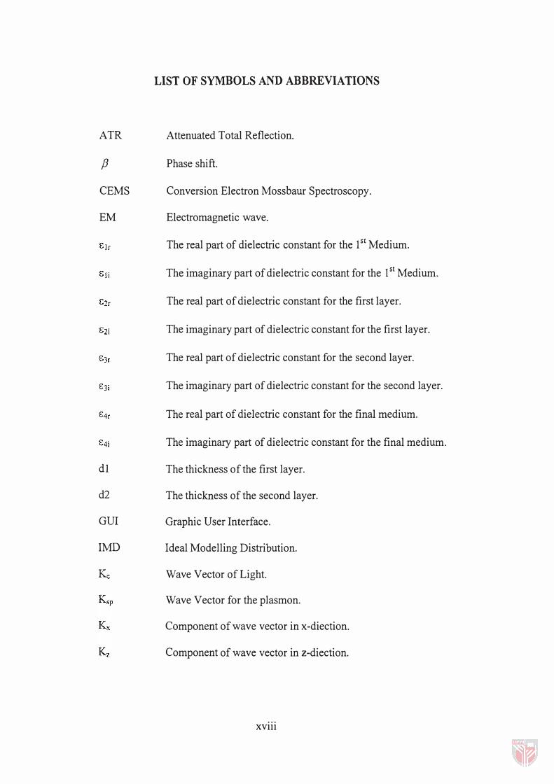
Attenuated Total Reflection.
Phase shift.
Conversion Electron Mossbaur Spectroscopy.
Electromagnetic wave.
The real part of dielectric constant for the 1st Medium.
The imaginary part of dielectric constant for the 1st Medium.
The real part of dielectric constant for the first layer.
The imaginary part of dielectric constant for the first layer.
The real part of dielectric constant for the second layer.
The imaginary part of dielectric constant for the second layer.
The real part of dielectric constant for the final medium.
The imaginary part of dielectric constant for the final medium.
The thickness of the first layer.
The thickness of the second layer.
Graphic User Interface.
Ideal Modelling Distribution.
Wave Vector of Light.
Wave Vector for the plasmon.
Component of wave vector in x-diection.
Component of wave vector in z-diection.
xviii
LSF Least Square Fitting.
Jl Magnetic permittivity.
PSA Phase Space Analysis.
(j Specific conductivity.
rp reflection coefficient for wave incidence parallel to the plane of incident.
rs reflection coefficient for wave incidence perpendicular to the plane of incident.
R( A. ) Reflectance versus wavelength.
R( e) Reflectance versus incidence angle.
S scattering matrix.
SP Surface Plasmon.
SPP Surface Plasmon Polaritons.
SPR Surface Plasmon Resonance.
STM Scanning Tunneling Microscopy.
TIR Total Internal Reflection.
tp Transmission coefficient for wave incident parallel to the plane of incident.
t5 Transmission coefficient for wave incident perpendicular to the plane of incident.
T( A.) Transmission versus wavelength.
T( e) Transmission versus incident angle.
OJ Frequency.
OJ p Natural plasma frequency.
XRR X-Ray Reflectance.
xix
CHAPTER I
INTRODUCTION
Objective
The objective of this project is to develop a computer program for properties
of multilayered system. This is done by computing reflection and transmission for
such a system. The effect of multiple scattering for such system had led by using
scattering matrix techniques. The computation is done with Visual Basic as
programming language. The choice of language is a matter of convenience for it is
graphic user interface (GUI) and event-driven programming in windows system.
Surface Plasmon Resonance (SPR)
The surface plasmons are charge density waves which propagate along the
surface of plasma. Any system which can be approximated as plasma will exhibit the
phenomena. For example, electrons in metal can be approximated as free electrons
systems.
2
Hence metal sheet can be treated as a plasmon slab. Then it is possible to excite
plasmons on the surfaces of metals. The surface plasmon resonance technique is a
technique of generating surface plasma waves using appropriately applied
perturbation such as light waves. Since the technique probes the surface of metals,
hence any surface effect can be detected.
SPR has been applied in the development of gas sensor, measurement of
optical properties of metals and degeneration monitoring of metals (Agranovich and
Mills, 1982). SPR has an extensive range of applications in the analysis of metals
because the resonance condition depends upon the physical properties of metal
surface on which the plasmon is excited. SPR is one of the most sensitive technique
to probe surface and interface effects. This inherent property makes SPR well suited
for nondestructive studies of surfaces, interfaces, and very thin layers (Kryakov,
1997). Surface plasmons can be excited by either electron beams or light rays.
However surface plasmons cannot be normally excited optically in metal- dielectric
interface because the dispersion relation for SPR and incident light do not match at
any frequency. This restriction however can be overcome by using the prism (see
figure 1).
SPR Principle
Surface plasmon resonance is an opto-electrical phenomenon arising from the
interaction of light with free electrons in metal surface. Under certain conditions
3
Incident light Reflected light
ATR prism
rIll IIIZZt-substrate
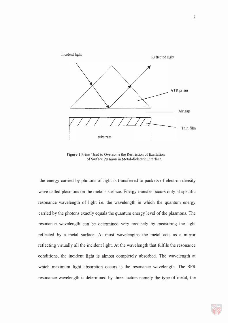
Figure 1 Prism Used to Overcome the Restriction of Excitation of Surface Plasmon in Metal-dielectric Interface.
Air gap
Thin film
the energy carried by photons of light is transferred to packets of electron density
wave called plasmons on the metal's surface. Energy transfer occurs only at specific
resonance wavelength of light i.e. the wavelength in which the quantum energy
carried by the photons exactly equals the quantum energy level of the plasmons. The
resonance wavelength can be determined very precisely by measuring the light
reflected by a metal surface. At most wavelengths the metal acts as a mirror
reflecting virtually all the incident light. At the wavelength that fulfils the resonance
conditions, the incident light is almost completely absorbed. The wavelength at
which maximum light absorption occurs is the resonance wavelength. The SPR
resonance wavelength is determined by three factors namely the type of metal, the
4
structure of the metal's surface, and the nature of the medium in contact with the
metal surface [F euerbacher et ai., ( 1 978) Garcia and Perdry, ( 1 994)].
The Metal
To use SPR, a material must have conduction band electrons capable of
resonating with light at suitable wavelength. The visible and near-infrared parts of
the spectrum are particularly convenient because optical components and light
performance detectors appropriate for this region are readily available. A variety of
metallic elements satisfy this condition. They include silver, gold, copper,
aluminum, sodium, and indium. The surface exposed to light must be pure metal
(Garcia and Perdry, 1 994).
The Surface
The resonance condition that permits energy transfer from photons to
plasmons depends upon a quantum mechanical criterion related to the energy and
momentum of the photons and plasmons. Both the energy and momentum of the
photon must match exactly the energy and momentum of the plasmons. For a flat
metal surface, there is no wavelength of light that satisfies this constraint. Hence,
there can be no surface plasmon resonance (Feuerbacher et aI., 1 978). The metal
surfaces are considerably smoother electronically than semiconductor surfaces
because of the delocalised electron on metallic boundary. Even though the localized