Università di Padova Facoltà di Scienze MM.FF.NN ... · Package Diagram Communication Diagram...
37
© Renato Conte - UML: diagrammi di implementazione - 1 / 37 - UML other structural diagrams (Implementation Diagrams UML 1.5) Università di Padova Facoltà di Scienze MM.FF.NN Informatica - anno 2009-10 Corso di Ingegneria del Software - B v 2.3
Transcript of Università di Padova Facoltà di Scienze MM.FF.NN ... · Package Diagram Communication Diagram...
© Renato Conte - UML: diagrammi di implementazione - 1 / 37 -
UMLother structural
diagrams (Implementation Diagrams UML 1.5)
Università di Padova
Facoltà di Scienze MM.FF.NN
Informatica - anno 2009-10
Corso di Ingegneria del Software - B
v 2.3
© Renato Conte - UML: diagrammi di implementazione - 2 / 37 -
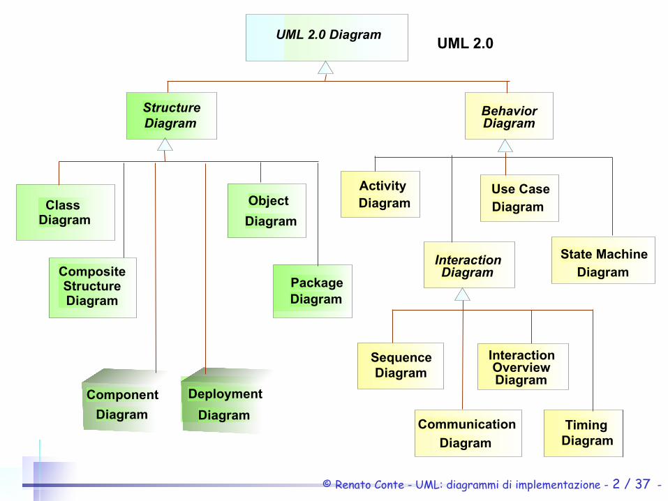
UML 2.0 Diagram
StructureDiagram
BehaviorDiagram
InteractionDiagram
Use CaseDiagram
ActivityDiagram
CompositeStructureDiagram
Class Diagram
Component
Diagram
Deployment
Diagram
SequenceDiagram
InteractionOverviewDiagram
Object
Diagram
State MachineDiagram
PackageDiagram
Communication
DiagramTiming
Diagram
UML 2.0
© Renato Conte - UML: diagrammi di implementazione - 3 / 37 -
Use CaseDiagrams
CollaborationDiagrams
ComponentComponentDiagramsDiagrams
DeploymentDeploymentDiagramsDiagrams
ObjectDiagrams
StatechartDiagrams
SequenceDiagrams
ClassDiagrams
ActivityDiagrams
Design
Implementation
Analysis
Test
Requirements Use CaseModel
DesignModel
DeploymentModel
Implem.Model
AnalysisModel
TestModel
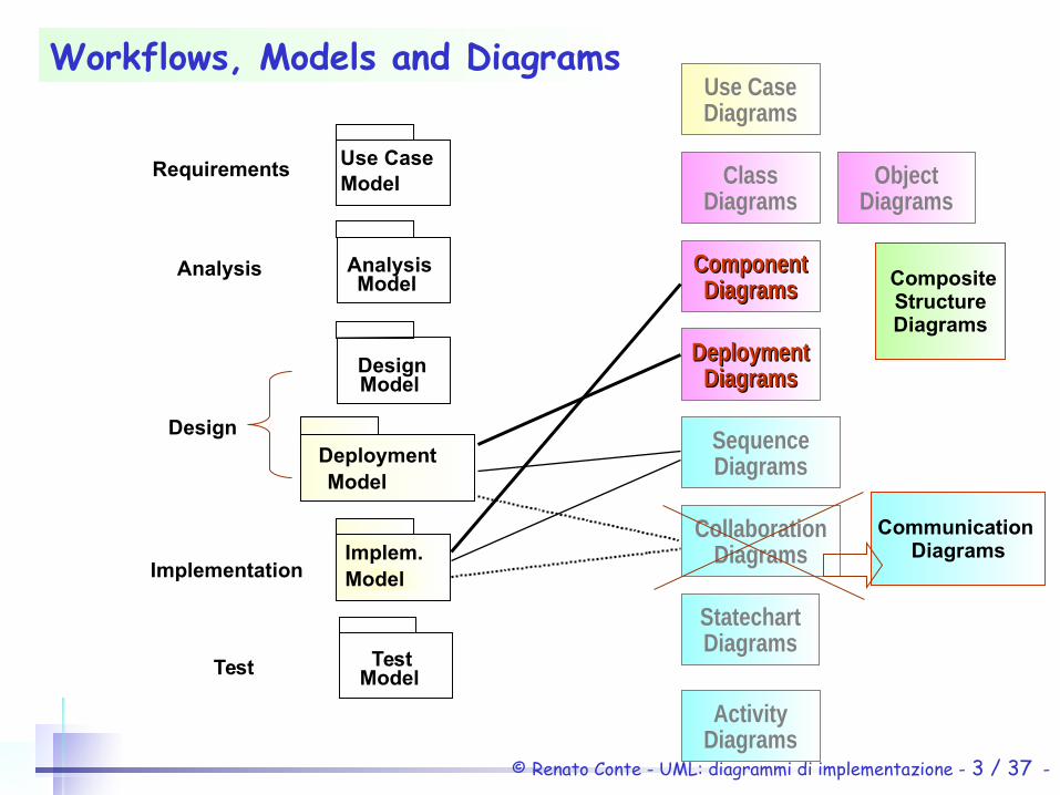
Workflows, Models and Diagrams
Composite
StructureDiagrams
Communication
Diagrams
© Renato Conte - UML: diagrammi di implementazione - 4 / 37 -
Implementation diagrams
There are two types of implementation diagrams, both concerned with the physical details of system organization
• Component diagrams which show the relationships between software artifacts.
• Deployment diagrams (trad.it. “diagrammi di messa in opera”) which show the relationships between hardware and software artifacts.
© Renato Conte - UML: diagrammi di implementazione - 5 / 37 -
Component is
“a physical and replaceable part of a system that conforms to and provides the realization of a set of interfaces.”
User guide
© Renato Conte - UML: diagrammi di implementazione - 6 / 37 -
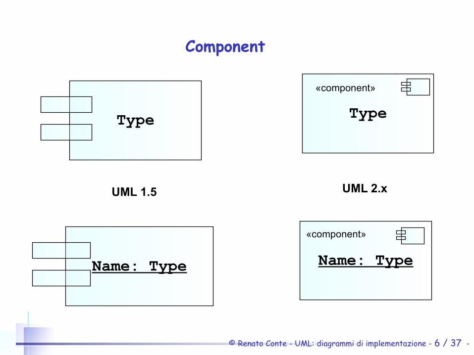
Component
Name: Type
Type Type
Name: Type
«component»
«component»
UML 1.5 UML 2.x

© Renato Conte - UML: diagrammi di implementazione - 7 / 37 -
Components and classes
fraudagent.dll
FraudAgent
FraudPolicy
PatternSearch
( rarely drawn )

© Renato Conte - UML: diagrammi di implementazione - 8 / 37 -
Components and interfaces (UML 2.x and 1.5)
image.java component.java
ImageObserver
image.java component.java
«interface»ImageObserver
abort:int{final static}error:int{final static}
imageUpdate():Boolean
© Renato Conte - UML: diagrammi di implementazione - 9 / 37 -
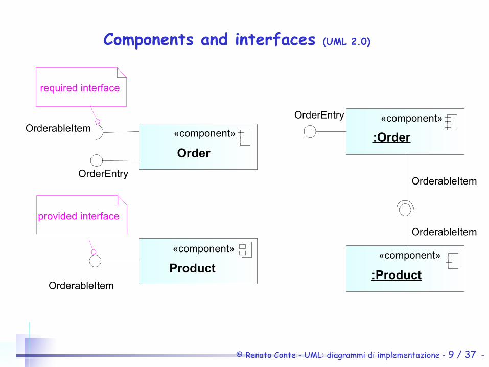
Components and interfaces (UML 2.0)
Product
«component»
OrderableItem:Order
:Product
OrderableItem
OrderableItem
«component»
«component»
provided interface
Order
«component»
OrderableItem
required interface
OrderEntry
OrderEntry
© Renato Conte - UML: diagrammi di implementazione - 10 / 37 -
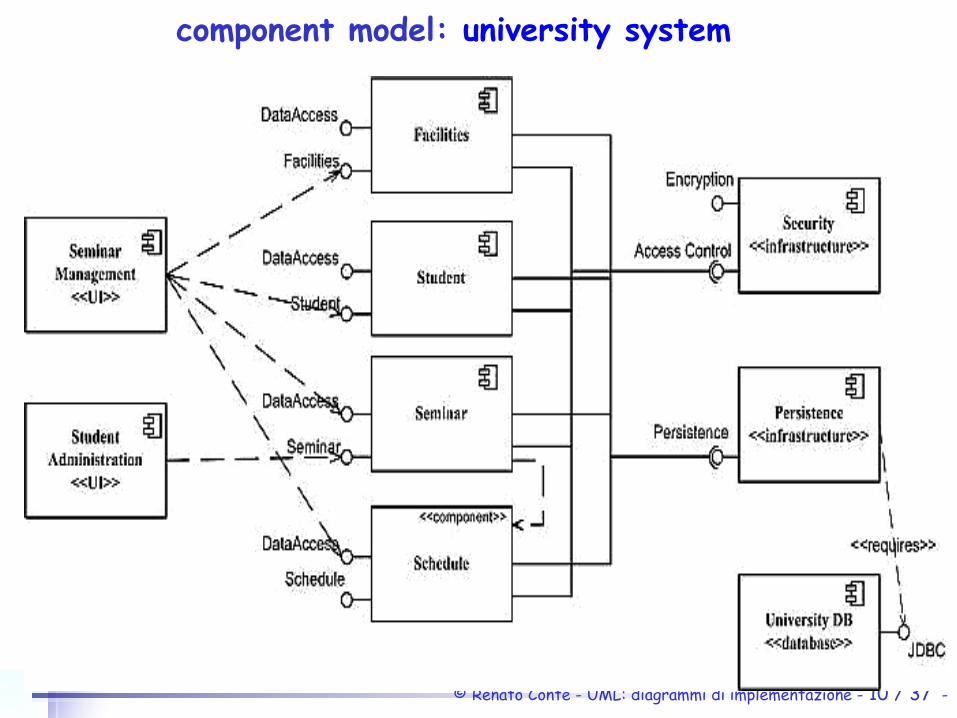
component model: university system

© Renato Conte - UML: diagrammi di implementazione - 11 / 37 -
component model for a university system
As you can see UML 2 uses this symbol as a visual stereotype within the rectangle to indicate that the rectangle represents a component although the textual stereotype of component is also acceptable (as you see with the Schedule component). Both diagrams model dependencies, either between components or between components and interfaces. You can also see that both diagrams use the lollipop symbol to indicate an implemented interface although the UML 2 version introduces the socket symbol to indicate a required interface. As far as I’m concerned the socket symbol is effectively a visual stereotype applied to a dependency, the equivalent textual stereotype is shown on the dependency between the Persistence component and the JDBC interface.
© Renato Conte - UML: diagrammi di implementazione - 12 / 37 -
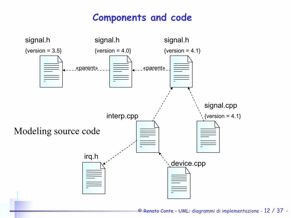
Components and code
signal.h
{version = 3.5}
signal.h
{version = 4.1}
signal.h
{version = 4.0}
signal.cpp
{version = 4.1}interp.cpp
device.cppirq.h
«parent» «parent»
Modeling source code
© Renato Conte - UML: diagrammi di implementazione - 13 / 37 -
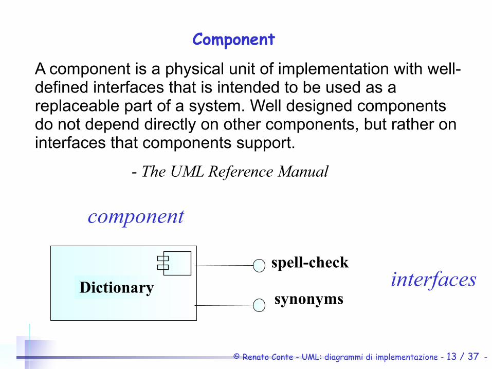
Component
A component is a physical unit of implementation with well-defined interfaces that is intended to be used as a replaceable part of a system. Well designed components do not depend directly on other components, but rather on interfaces that components support.
- The UML Reference Manual
component
interfacesspell-check
Dictionarysynonyms
© Renato Conte - UML: diagrammi di implementazione - 14 / 37 -
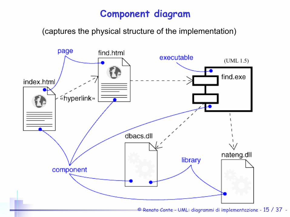
Component diagram
Component diagrams are one of the two kinds of diagrams found in modeling the physical aspects of an object-oriented system. They show the organization and dependencies between a set of components.
Use component diagrams to model the static implementation view of a system. This involves modeling the physical things that reside on a node, such as executables, libraries, tables, files, and documents.
- The UML User Guide
© Renato Conte - UML: diagrammi di implementazione - 15 / 37 -
Component diagram
(captures the physical structure of the implementation)
(UML 1.5)
© Renato Conte - UML: diagrammi di implementazione - 16 / 37 -
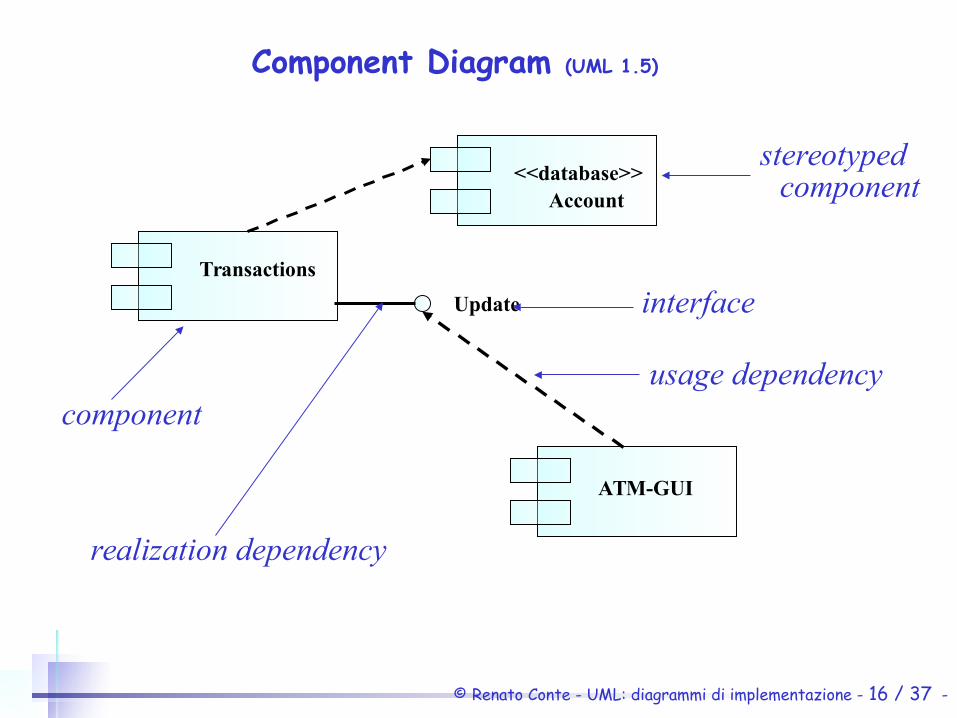
Component Diagram (UML 1.5)
Update
Transactions
Account
ATM-GUI
<<database>>
component
realization dependency
interface
usage dependency
stereotypedcomponent

© Renato Conte - UML: diagrammi di implementazione - 17 / 37 -
component diagram
• Captures the physical structure of the implementation
• Built as part of architectural specification
• Purpose– Organize source code– Construct an executable release– Specify a physical database
• Developed by architects and programmers
© Renato Conte - UML: diagrammi di implementazione - 18 / 37 -
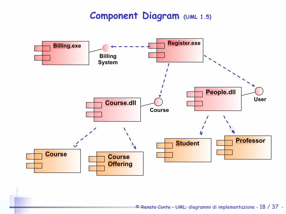
Component Diagram (UML 1.5)
Course CourseOffering
Student Professor
Course.dll
People.dll
Course
User
Register.exeBilling.exe
BillingSystem
© Renato Conte - UML: diagrammi di implementazione - 19 / 37 -
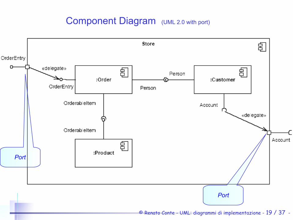
Component Diagram (UML 2.0 with port)
Port
Port

© Renato Conte - UML: diagrammi di implementazione - 20 / 37 -
Component stereotypes
«executable» Specifies a component that may be executed on a node
«library» Specifies a static or dynamic object library
«table» Specifies a component that represents a database table
«file» Specifies a component that represents a document containing source code or data
«document» Specifies a component that represents a document
© Renato Conte - UML: diagrammi di implementazione - 21 / 37 -
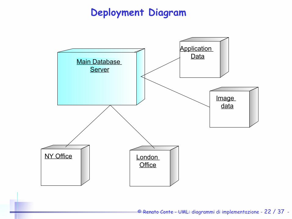
Deployment Diagram (trad.it. “diagrammi di messa in opera”)
• Shows the configuration of run-time processing elements and the software components, processes and objects that live on them
• Deployment diagrams may be used to show which components may run on which nodes
© Renato Conte - UML: diagrammi di implementazione - 22 / 37 -
Deployment Diagram
Main Database Server
Application Data
Image data
NY Office London Office

© Renato Conte - UML: diagrammi di implementazione - 23 / 37 -
Application client
<<workstation>> Application Server<<server>
>
Oracle
<<DBMS server>>
Tomcat
<<Web server>>Web
Application
<<Servlet library>>
MS IE
<<Web browser>>
App Database
<<Database>>
SQL
Database administrator
<<workstation>>
SQL Plus<<DBMS client>>
TCP
Internet connection
LAN connection
HTTP
<<protocol>>
<<protocol>>
CGI
JDBC
<<session>>
<<session>>
<<session>>
OS connection
Web server administrator<<workstation>>
Netscape
<<Web Browser>>
HTTP<<protocol>>
© Renato Conte - UML: diagrammi di implementazione - 24 / 37 -
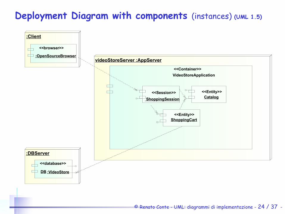
Deployment Diagram with components (instances) (UML 1.5)
:DBServer
videoStoreServer :AppServer
<<Container>>
VideoStoreApplication
:Client
<<browser>>
:OpenSourceBrowser
<<Session>>
ShoppingSession
<<Entity>>Catalog
<<Entity>>ShoppingCart
<<database>>
:VideoStoreDB
© Renato Conte - UML: diagrammi di implementazione - 25 / 37 -
Deployment Diagrams
Deployment diagrams are one of the two kinds of diagrams found in modeling the physical aspects of an object-oriented system. They show the configuration of run-time processing nodes and the components that live on them.
- The UML User Guide

© Renato Conte - UML: diagrammi di implementazione - 26 / 37 -
Components in a deployment diagram
• Components represent runtime manifestations of code units.
• Components that do not exist as run-time entities do not appear on these diagrams; they should be shown on component diagrams.
• A deployment diagram shows instances whereas a component diagram shows the definition of component types themselves.
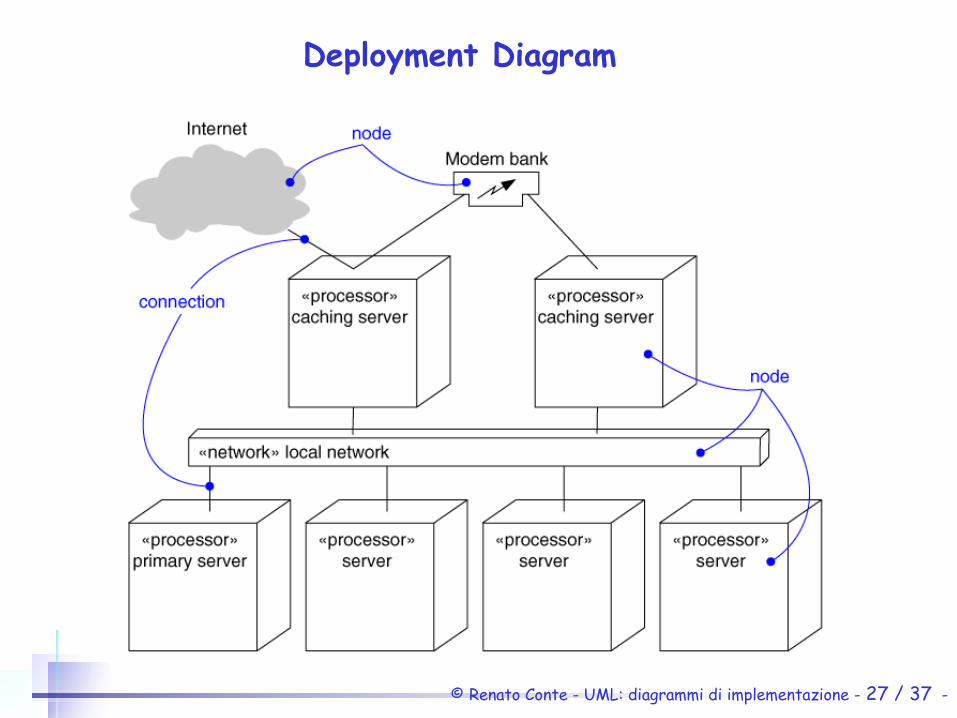
© Renato Conte - UML: diagrammi di implementazione - 27 / 37 -
Deployment Diagram
© Renato Conte - UML: diagrammi di implementazione - 28 / 37 -
Deployment Diagram
• Captures the topology of a system’s hardware• Built as part of architectural specification
• Purpose:– Specify the distribution of components– Identify performance bottlenecks
• Developed by architects, networking engineers, and system engineers
© Renato Conte - UML: diagrammi di implementazione - 29 / 37 -
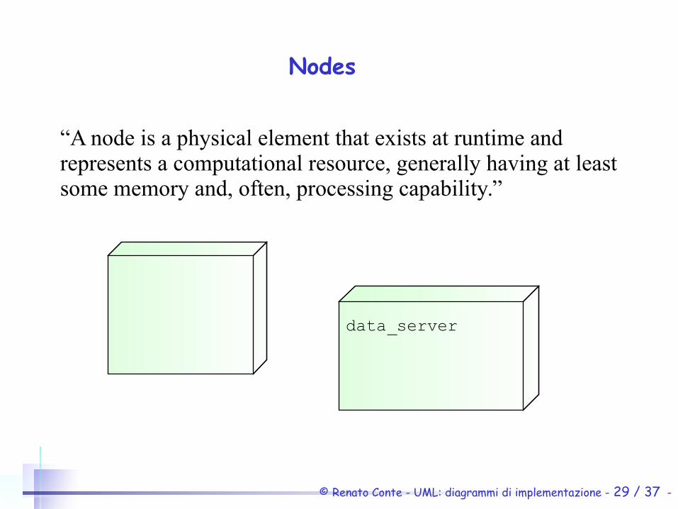
Nodes
“A node is a physical element that exists at runtime and represents a computational resource, generally having at least some memory and, often, processing capability.”
data_server
© Renato Conte - UML: diagrammi di implementazione - 30 / 37 -
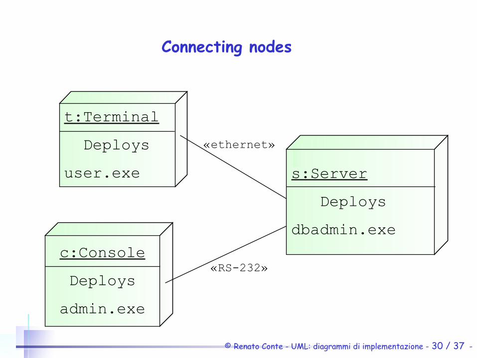
Connecting nodes
«ethernet»
s:Server
Deploys
dbadmin.exe
c:Console
Deploys
admin.exe
t:Terminal
Deploys
user.exe
«RS-232»
© Renato Conte - UML: diagrammi di implementazione - 31 / 37 -
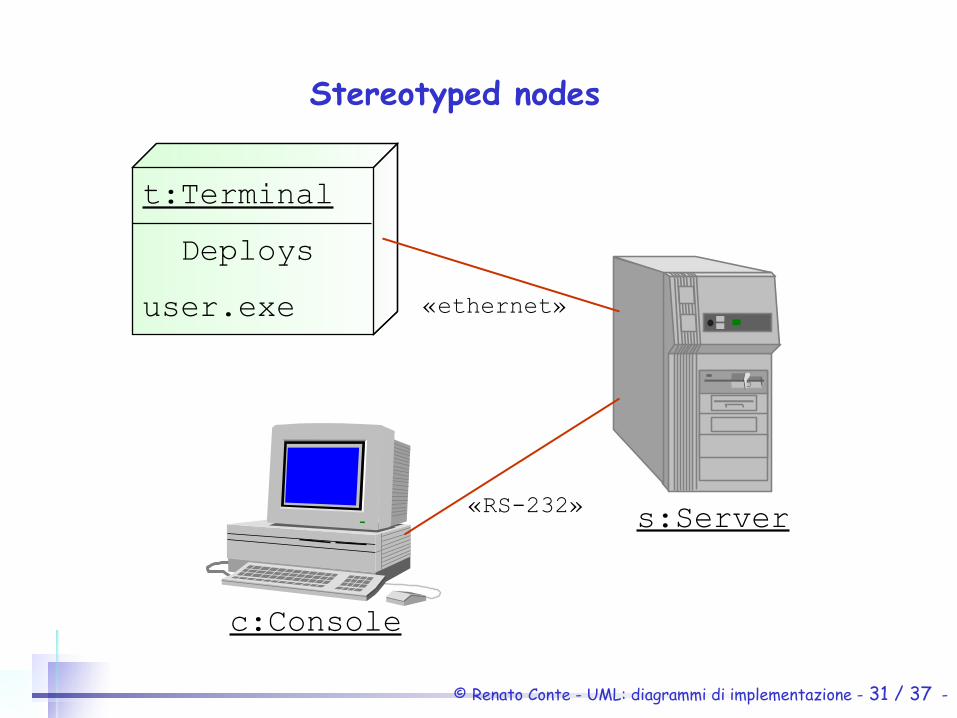
Stereotyped nodes
t:Terminal
Deploys
user.exe
s:Server
c:Console
«ethernet»
«RS-232»

© Renato Conte - UML: diagrammi di implementazione - 32 / 37 -
Deployment Diagram with Stereotyped
© Renato Conte - UML: diagrammi di implementazione - 33 / 37 -
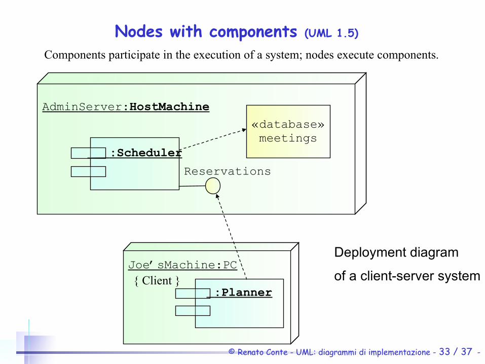
Joe’sMachine:PC
AdminServer:HostMachine
Nodes with components (UML 1.5)
:Scheduler
:Planner
«database»meetings
Reservations
Components participate in the execution of a system; nodes execute components.
Deployment diagram
of a client-server system{ Client }
© Renato Conte - UML: diagrammi di implementazione - 34 / 37 -
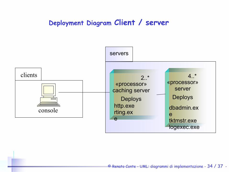
console
«processor»caching server
Deploys
clients
http.exerting.exe
2..*«processor»
server
Deploys
dbadmin.exetktmstr.exelogexec.exe
4..*
servers
Deployment Diagram Client / server
© Renato Conte - UML: diagrammi di implementazione - 35 / 37 -
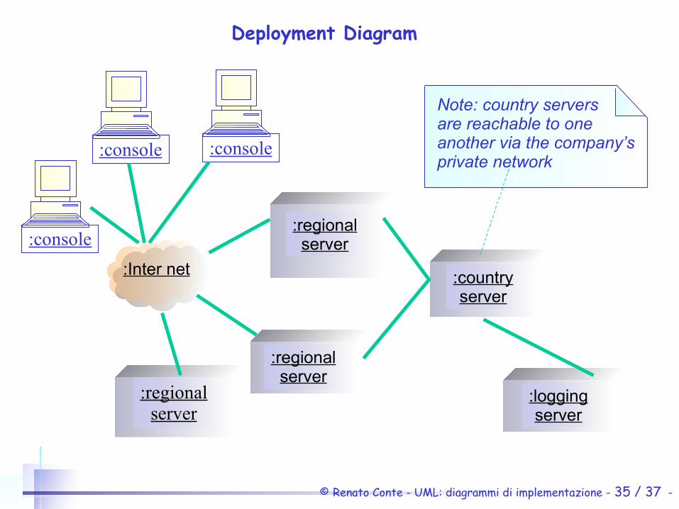
:console
:console :console
:Inter net
:regionalserver
:regionalserver
:regionalserver
:countryserver
:loggingserver
Note: country serversare reachable to one another via the company’sprivate network
Deployment Diagram
© Renato Conte - UML: diagrammi di implementazione - 36 / 37 -
Bibliography
Grady Booch, James Rumbaugh, Ivar Jacobson. The Unified Modeling Language User Guide, Addison Wesley , (1999).
Grady Booch, James Rumbaugh, Ivar JacobsonThe Unified Modeling Language Reference Manual , Addison Wesley, (1999).
Ivar Jacobson, Grady Booch, James Rumbaugh The Unified Software Development Process,Addison Wesley, (1999).
© Renato Conte - UML: diagrammi di implementazione - 37 / 37 -
Web referencesOMG UML - www.omg.org/uml/
Unified Modeling Language: Superstructureversion 2.1.1 formal/2007-02-03
UML: tool, demo, docwww.rational.com
UML: Tutorial e link www.kobryn.comwww.cetus-links.org/oo_uml.html