UNIVERSAL TECHNICIAN - T-Systems I CERTIFICATION ... The EPA also reserves the right to modify the...
18
for AIR CONDITIONING & REFRIGERATION TECHNICIANS Federal Clean Air Act - Section 608 CONTAINS ALL OF THE INFORM ATION AIR CONDITIONING AND REFRIGERATION SERVICE PERSONNEL W ILL NEED TO SUCCESSFULLY BECOM E CERTIFIED AS A UNIVERSAL TECHNICIAN
Transcript of UNIVERSAL TECHNICIAN - T-Systems I CERTIFICATION ... The EPA also reserves the right to modify the...
for
AIR CONDITIONING & REFRIGERATION
TECHNICIANSFederal Clean Air Act - Section 608
CONTAINS ALL OF THE INFORM ATION AIR CONDITIONING AND
REFRIGERATION SERVICE PERSONNEL W ILL NEED TO
SUCCESSFULLY BECOM E CERTIFIED AS A
UNIVERSAL TECHNICIAN
This manual was developed by The ESCO INSTITUTE
Mount Prospect, IL 60056
ESCO Institute
P.O. Box 521
Mount Prospect, IL. 60056
Phone: 1(800) 726-9696 Fax: 1(800) 546-3726
Web site: http://www.escoinst.com E-Mail: vbaker@ escoinst.com
COPYRIGHT 2001 ESCO PRESS
All rights reserved
Printed in The United States of America
ISBN 1-930044-01-1
No part of this manual may be reproduced, stored in a retrieval system, or transmitted by any means,
electronic, mechanical, photocopying, recording, or otherwise, without written permission of the authors.
No patent liability is assumed with respect to the use of the information contained herein. While every
precaution has been taken in the preparation of this book, the authors and publisher assume no
responsibility for errors or omissions. Neither is any liability assumed for damages resulting from the
use of the information contained herein.
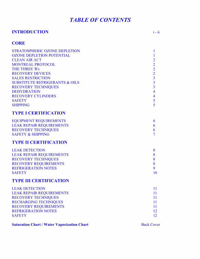
TABLE OF CONTENTS
INTRODUCTION i - ii
CORE
STRATOSPHERIC OZONE DEPLETION 1
OZONE DEPLETION POTENTIAL 1
CLEAN AIR ACT 2
MONTREAL PROTOCOL 2
THE THREE 'R's 2
RECOVERY DEVICES 2
SALES RESTRICTION 3
SUBSTITUTE REFRIGERANTS & OILS 3
RECOVERY TECHNIQUES 3
DEHYDRATION 4
RECOVERY CYLINDERS 4
SAFETY 5
SHIPPING 5
TYPE I CERTIFICATION
EQUIPMENT REQUIREMENTS 6
LEAK REPAIR REQUIREMENTS 6
RECOVERY TECHNIQUES 6
SAFETY & SHIPPING 7
TYPE II CERTIFICATION
LEAK DETECTION 8
LEAK REPAIR REQUIREMENTS 8
RECOVERY TECHNIQUES 8
RECOVERY REQUIREMENTS 8
REFRIGERATION NOTES 9
SAFETY 10
TYPE III CERTIFICATION
LEAK DETECTION 11
LEAK REPAIR REQUIREMENTS 11
RECOVERY TECHNIQUES 11
RECHARGING TECHNIQUES 11
RECOVERY REQUIREMENTS 11
REFRIGERATION NOTES 12
SAFETY 12
Saturation Chart / Water Vaporization Chart Back Cover
INTRODUCTION This manual is intended to prepare technicians for the certification test, and contains all the information a technician will
require to successfully complete the test. This booklet is not intended to be a formal refrigeration training course.
Technicians should be familiar with the basic vapor - compression refrigeration cycle and common service equipment and
procedures.
This manual has been assembled with the most current information available at the time of this edition. Should EPA
regulations change after a technician becomes certified, it is the responsibility of the technician to comply with any future
changes. The EPA also reserves the right to modify the test questions and or call for a new certification based on
advancements in future technology. The ESCO Institute will update this manual as necessary to keep current with EPA
rulings.
Section 608 of the Federal Clean Air Act requires that all persons who maintain, service, repair, or dispose of appliances
that contain regulated refrigerants, be certified in proper refrigerant handling techniques as of November 14, 1994.
There are four (4) categories of technician certification:
TYPE I Persons who maintain, service or repair small appliances must be certified as Type I technicians.
TYPE II Persons, who maintain, service, repair or dispose of high or very high-pressure appliances, except small appliances and
motor vehicle air conditioning systems, must be certified as Type II technicians.
TYPE III Persons, who maintain, service, repair, or dispose of low-pressure appliances must be certified as Type III technicians.
UNIVERSAL Persons, who maintain, service or repair both low and high-pressure equipment, as well as small appliances, must be
certified as Universal technicians.
TEST FORMAT
The test contains four sections, A - I - II - Ill. Each section contains twenty five (25) multiple-choice questions. A
technician MUST achieve a minimum passing score of 70 percent in each group in which they are to be certified. For
instance a technician seeking Universal certification must achieve a minimum score of 70 percent, or 18 out of 25 correct,
on each of the Sections of the test. If a technician fails one or more of the Sections on the first try, they may retake the
failed Section(s) without retaking the Section(s) on which they earned a passing score. In the meantime the technician
will be certified in the Type in which they received a passing score. There is one exception; a technician MUST achieve a
passing score on Section A to receive any certification.
Section A contains 25 general knowledge questions concerning stratospheric ozone depletion, rules and regulations of the
Clean Air Act, the Montreal Protocol, refrigerant recovery, recycling and reclaiming, recovery devices, substitute
refrigerants and oils, recovery techniques, dehydration, recovery cylinders, safety, and shipping. Section I contains 25
sector specific questions pertaining to small appliances. Section II contains 25 sector specific questions pertaining to high-
pressure appliances and Section III contains 25 sector specific questions pertaining to low-pressure appliances.
The law requires the test to be a closed book exam. The only outside materials allowed are a temperature / pressure chart
and a calculator.
Certain personal information is required on the exam. Technicians should be prepared to present:
♦ Picture identification
♦ Social security number
♦ Home address
Technicians should carefully study Sections A and the Section(s) related to the Type of certification in which they are
seeking to achieve a passing score.
1
F LO W
34
5
2 6
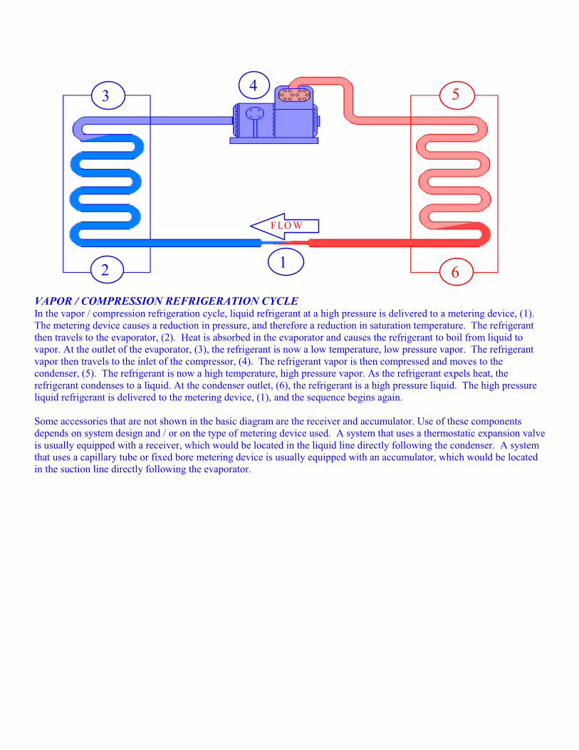
VAPOR / COMPRESSION REFRIGERATION CYCLE In the vapor / compression refrigeration cycle, liquid refrigerant at a high pressure is delivered to a metering device, (1).
The metering device causes a reduction in pressure, and therefore a reduction in saturation temperature. The refrigerant
then travels to the evaporator, (2). Heat is absorbed in the evaporator and causes the refrigerant to boil from liquid to
vapor. At the outlet of the evaporator, (3), the refrigerant is now a low temperature, low pressure vapor. The refrigerant
vapor then travels to the inlet of the compressor, (4). The refrigerant vapor is then compressed and moves to the
condenser, (5). The refrigerant is now a high temperature, high pressure vapor. As the refrigerant expels heat, the
refrigerant condenses to a liquid. At the condenser outlet, (6), the refrigerant is a high pressure liquid. The high pressure
liquid refrigerant is delivered to the metering device, (1), and the sequence begins again.
Some accessories that are not shown in the basic diagram are the receiver and accumulator. Use of these components
depends on system design and / or on the type of metering device used. A system that uses a thermostatic expansion valve
is usually equipped with a receiver, which would be located in the liquid line directly following the condenser. A system
that uses a capillary tube or fixed bore metering device is usually equipped with an accumulator, which would be located
in the suction line directly following the evaporator.
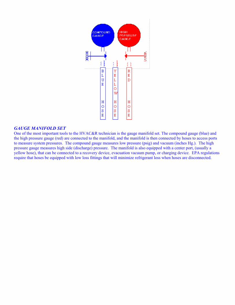
GAUGE MANIFOLD SET One of the most important tools to the HVAC&R technician is the gauge manifold set. The compound gauge (blue) and
the high pressure gauge (red) are connected to the manifold, and the manifold is then connected by hoses to access ports
to measure system pressures. The compound gauge measures low pressure (psig) and vacuum (inches Hg.). The high
pressure gauge measures high side (discharge) pressure. The manifold is also equipped with a center port, (usually a
yellow hose), that can be connected to a recovery device, evacuation vacuum pump, or charging device. EPA regulations
require that hoses be equipped with low loss fittings that will minimize refrigerant loss when hoses are disconnected.
CORESECTION A
GENERAL KNOWLEDGE
STRATOSPHERIC OZONE DEPLETION The introduction of CFC’s and HCFC’s has dramatically changed our lifestyles. Little did we know that the use and
release of these compounds into the atmosphere would have far reaching effects on our environment. The greatest effect is
in the stratosphere, far removed from the Earth's surface.
The stratosphere is the Earth's security blanket. It is located between 10 and 30 miles above sea level and is comprised of,
among other things, Ozone. An Ozone molecule consists of three oxygen atoms (03). Ozone protects us from harmful
ultraviolet radiation and helps maintain stable Earth temperatures. Stratospheric Ozone depletion is a global problem.
Depletion of Ozone in the stratosphere causes:
♦ CROP LOSS
♦ INCREASE IN EYE DISEASES
♦ SKIN CANCER
♦ REDUCED MARINE LIFE
♦ DEFORESTATION
♦ INCREASED GROUND LEVEL OZONE
CFC’s have been found in air samples taken from the stratosphere. CFC's and HCFC's, when released into the atmosphere
deplete the Ozone layer. The chlorine in these compounds is the culprit. When a chlorine atom meets with an Ozone
molecule, it takes one Oxygen atom from the Ozone.This forms a compound called Chlorine Monoxide (CIO) and leaves
an O2 molecule. The Chlorine Monoxide will collide with another Ozone molecule, release its Oxygen atom, forming two
O2 molecules, and leave the chlorine free to attack another Ozone molecule. A single Chlorine atom can destroy 100,000
Ozone molecules.
There has been a great deal of controversy over the subject of Ozone depletion. Some believe that the Chlorine found in
the stratosphere comes from natural sources such as volcanic eruptions. However, air samples taken over erupting
volcanoes show that volcanoes contribute only a small quantity of Chlorine as compared to CFC's. In addition, the rise in
the amount of Chlorine measured in the stratosphere over the past two decades matches the rise in the amount of Fluorine,
which has different natural sources than Chlorine, over the same period. Also, the rise in the amount of Chlorine measured
in the stratosphere over the past twenty years, matches the rise in CFC emissions over the same period.
Unlike other Chlorine compounds and naturally occurring chlorine, the chlorine in CFC's will neither dissolve in water
nor break down into compounds that dissolve in water, so they do not rain out of the atmosphere.
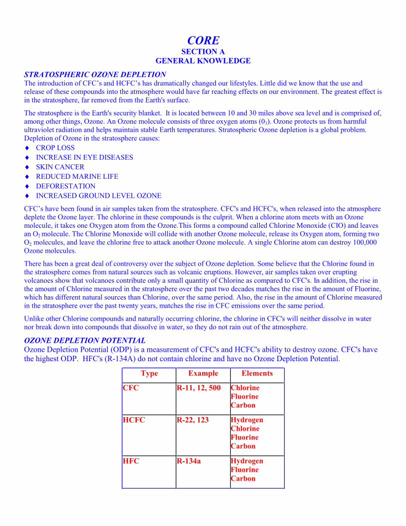
OZONE DEPLETION POTENTIAL
Ozone Depletion Potential (ODP) is a measurement of CFC's and HCFC's ability to destroy ozone. CFC's have
the highest ODP. HFC's (R-134A) do not contain chlorine and have no Ozone Depletion Potential.
Type Example Elements
CFC R-11, 12, 500 Chlorine
Fluorine
Carbon
HCFC R-22, 123 Hydrogen
Chlorine
Fluorine
Carbon
HFC R-134a Hydrogen
Fluorine
Carbon
CLEAN AIR ACT The United States Environmental Protection Agency (EPA) regulates section 608 of the Federal Clean Air Act. Failure to comply could cost you and your company as much as $27,500. per day, per violation and there is a bounty of up to $10,000. To lure your competitors, customers and fellow workers to turn you in. Service technicians who violate Clean Air Act provisions may be fined, lose their certification, and may be required to appear in Federal court. The EPA may require technicians to demonstrate the ability to properly perform refrigerant recovery/recycling procedures. Failing to demonstrate these skills can result in revocation of certification.
It is a violation of Section 608 to:
♦ Falsify or fail to keep required records;
♦ Fail to reach required evacuation rates prior to opening or disposing of appliances;
♦ Knowingly release (vent) CFC's, HCFC's or HFC’s while repairing appliances, with the exception of de-minimus releases;
♦ Service, maintain, or dispose of appliances designed to contain refrigerants without being appropriately certified as of November 14, 1994. (It is the responsibility of the final person in the disposal chain to ensure that refrigerant has been removed from appliances before scrapping.)
♦ Vent CFC's or HCFC's since July 1, 1992;
♦ Vent HFC's since November 15, 1995;
♦ Fail to recover CFC's, HCFC's or HFC’s before opening or disposing of an appliance;
♦ Fail to have an EPA approved recovery device, equipped with low loss fittings, and register the device with the EPA;
♦ Add nitrogen to a fully charged system, for the purpose of leak detection, and thereby cause a release of the mixture;
♦ Dispose of a disposable cylinder without first recovering any remaining refrigerant (to 0 psig.) and then rendering the cylinder useless, then recycling the metal;
In addition, some state and local government regulations may contain regulations that are as strict or stricter than Section 608.
MONTREAL PROTOCOL Following several years of negotiations, an international agreement (Treaty) regulating the production and use of CFCs, HCFC’s, halons, methyl chloroform and carbon tetrachloride entered into force in mid 1989. Known as The Montreal Protocol, this landmark agreement initially required a production and consumption freeze. The Montreal Protocol called for a stepwise reduction and eventual production phase out of various Ozone Depleting Substances in developed countries. CFC's were phased out of production on December 31, 1995. HCFC refrigerants are scheduled of phase out in the future. When virgin supplies of CFC's are depleted, future supplies will come from recovered, recycled, or reclaimed refrigerants.
THE THREE "R's” (RECOVER - RECYCLE - RECLAIM)The processes of recovery, recycling, and reclaiming sound similar, but they are quite different.
To RECOVER is to remove refrigerant in any condition from a system and store it in an external container.
To RECYCLE is to clean refrigerant for rouse by separating the oil from the refrigerant and removing moisture from the refrigerant by passing it through one or more filter driers.
To RECLAIM is to process refrigerant to a level equal to new (virgin) product specifications as determined by chemical analysis. RECLAIMED refrigerant must meet the standard set forth in ARI 700 before it can be resold.
RECOVERY DEVICES Refrigerant Recovery and/or Recycling equipment manufactured after November 15, 1993, must be certified and labeled by an EPA approved equipment testing organization to meet EPA standards. There are two basic types of recovery devices.
One type of recovery equipment is referred to as “System-dependent” and captures refrigerant with the assistance of components in the appliance from which refrigerant is being recovered. The second type of recovery equipment is "Self-contained” and has its own means to draw the refrigerant out of the appliance.
SALES RESTRICTION As of November 14, 1994, the sale of CFC and HCFC refrigerants is restricted to certified technicians. Only technicians certified under Clean Air Act Section 609— Motor Vehicle Air Conditioning— are allowed to purchase refrigerants in containers smaller than 20 lbs.
SUBSTITUTE REFRIGERANTS AND OILS Our industry is in a state of change. New refrigerants, blends of older refrigerants, and different oils have appeared in the field.
R-134A is a HFC and is considered Ozone friendly. R-134A is the leading candidate for CFC R-12 retrofit, but it is not a drop-in substitute. Actually, there isn't a drop-in alternative, but R-134A can be used in most R-12 systems by following appropriate retrofit procedures. R-134A will not mix with most refrigerant oils. The oils used in most R-134A refrigeration systems are ESTERS. Esters cannot be mixed with other oils. It is also important to remember that when leak testing an R-134A system to use pressurized nitrogen.
There are several refrigerant blends commonly in use. Some of the blends are called Ternary, which means they are a three-part blend. Ternary blends are used with a synthetic alkylbenzene lubricant. Make certain you are using the correct oil for the refrigerant. Most refrigerant oils are hygroscopic. Hygroscopic oil has a high affinity for water. An oil sampleshould be taken and analyzed if a system has had a major component failure.
There is some specific information you will need to know about blends. First, the components of a blended refrigerant will leak from a system at uneven rates due to different vapor pressures. Second, the proper charging method for blended refrigerants is to weigh into the high side of the system as a liquid. A term you will need to know is “temperature glide”. Temperature glide refers to a refrigerant blend that has a range of boiling points or condensing points throughout the evaporator and condenser respectively
Other blends may be azeotropic. An azeotropic mixture that acts like a single component refrigerant over its entire temperature / pressure range. An azeotrope does not have a temperature glide.
RECOVERY TECHNIQUES Now that recovery is the law, many contractors have increased their service rates to help offset the cost of recovery equipment and recovery time. Some customers have complained about the increased cost of service. To justify the increase, simply explain that you are duty bound and required by law to recover refrigerants in order to protect the environment and human health.
EPA regulations require a service aperture or process stub on all appliances that use a Class I or Class II refrigerant in order to make it easier to recover refrigerant.
When servicing a system, if you discover that two or more refrigerants have been mixed in a system, you must recover the mixture into a separate tank. It is important NOT to mix different refrigerants in the same recovery tank because the mixture may be impossible to reclaim. Recover only one type of refrigerant into a recovery cylinder.
If a strong odor is detected during the recovery process, a compressor burn-out has likely occurred. When recovering refrigerant from a system that experienced a compressor burn-out, watch for signs of contamination in the oil. After recovering refrigerant, if nitrogen is used to flush debris out of the system, the nitrogen may be vented. A suction line filter drier should be installed to trap any debris that may damage the new compressor.
The length of the hose between the unit being recovered from and the recovery machine will greatly effect the efficiency of the recovery process. Long hoses will cause excessive pressure drop, increased recovery time, and have a potential for increased emissions. Since all refrigerants have a pressure temperature relationship, the lower the ambient temperature, the slower the recovery rate.
After completing the transfer of liquid refrigerant between a recovery unit and a refrigeration system, you should guard against trapping liquid refrigerant between the service valves.
DEHYDRATION Proper dehydration procedures through evacuation are important to follow.
As every technician knows, the reason for dehydrating a refrigeration system is to remove water and water vapor. If moisture is allowed to remain in an operating refrigeration system, hydrochloric and hydrofluoric acids may form. Evacuation of a system is the suggested method of dehydration. It is not possible to over evacuate a system.
Never evacuate a system to the ambient air without first following proper recovery procedures and attaining the mandated vacuum level. The factors affecting the speed and efficiency of evacuation are; size of equipment being evacuated, ambient temperature, amount of moisture in the system, the size of the vacuum pump and suction line. In addition, vacuum lines should be equal to or larger than the pump intake connection. The piping connection to the pump should be as short a length as possible and as large in diameter as possible. The system vacuum gauge should be connected as far as possible from the vacuum pump. Measuring a systems vacuum should be done with the system isolated and the vacuum pump turned off. A system that will not hold a vacuum probably has a leak. During evacuation you may wish to heat the refrigeration system to decrease dehydration time. Dehydration is complete when the vacuum gauge shows that you have reached and held the required finished vacuum. (See water vaporization chart in back of manual.)
RECOVERY CYLINDERS Recovery cylinders differ in many ways from disposable cylinders. Disposable cylinders are used only with virgin refrigerant and may NEVER be used for recovery.
Recovery cylinders are specifically designed to be refilled. Recovery cylinders have 2 ports, one liquid and one vapor. Care must be taken not to overfill or heat these cylinders, thereby causing an explosion. The EPA requires that a refillable refrigerant cylinder MUST NOT BE FILLED ABOVE 80% of its capacity by weight, and that the safe filling level can be controlled by either mechanical float devices, electronic shut off devices (thermistors), or weight. Refillable cylinders must be hydrostatically tested and date stamped every 5 years.
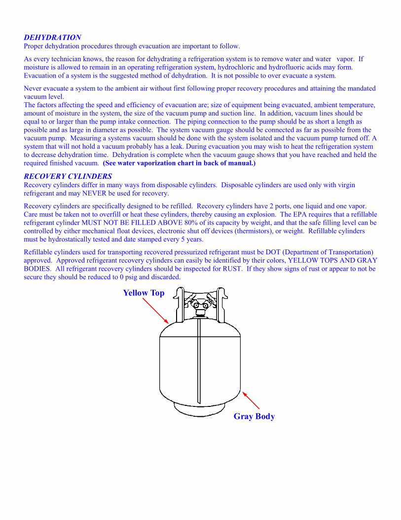
Refillable cylinders used for transporting recovered pressurized refrigerant must be DOT (Department of Transportation) approved. Approved refrigerant recovery cylinders can easily be identified by their colors, YELLOW TOPS AND GRAY BODIES. All refrigerant recovery cylinders should be inspected for RUST. If they show signs of rust or appear to not be secure they should be reduced to 0 psig and discarded.
Yellow Top
Gray Body
SAFETY The EPA is not only concerned with the prevention of refrigerant venting, but is also concerned with the technicians overall safety. When handling and filling refrigerant cylinders, or operating recovery or recycling equipment, you should wear safety glasses, protective gloves, and follow all equipment manufacturers safety precautions.
When pressurizing a system with nitrogen, you should always charge through a pressure regulator and insert a relief valve in the downstream line from the pressure regulator. Relief valves MUST NOT be installed in series. If corrosion build-up is found within the body of a relief valve, the valve MUST be replaced.
When leak checking a system, NEVER pressurize the system with oxygen or compressed air. When mixed with refrigerants, oxygen or compressed air can cause an explosion. To determine the safe pressure for leak testing, check the data plate for the low-side test pressure value.
When using recovery cylinders and equipment with Schrader valves, it is critical to inspect the Schrader valve core for leaks, bends and breakage, replace damaged valve cores to prevent leakage, and always cap Schrader ports to prevent accidental depression of the valve core. NEVER heat a refrigerant cylinder with an open flame. Do not cut or braze refrigerant lines on a charged unit.
In the event of a 'large" release of refrigerant in a confined area, Self Contained Breathing Apparatus (SCBA) is required. If a large leak of refrigerant occurs in an enclosed area, and SCBA is not available, IMMEDIATELY VACATE AND VENTILATE the area. In large quantities, refrigerants can cause suffocation because they are heavier than air and displace oxygen. Inhaling refrigerant vapors or mist may cause heart irregularities, unconsciousness, and oxygen deprivation leading to death (asphyxia).
NEVER expose R-12 or R-22 to open flames or glowing hot metal surfaces. At high temperatures, R-12 and R-22 decompose to form Hydrochloric acid, Hydrofluoric acid, and Phosgene gas.
Always review the material safety data sheets, when working with any solvents, chemicals, or refrigerants.
SHIPPING & TRANSPORTING Before shipping any used refrigerant cylinders, check that the cylinder meets DOT standards, complete the shipping paperwork including the number of cylinders of each refrigerant, and properly label the cylinder with the type and amount of refrigerant. Cylinders should be transported in an upright position. Each cylinder must be marked with a DOT classification tag indicating it is a “2.2 non-flammable gas”. Some states may require special shipping procedures to be followed based on their classification of used refrigerants. Check with the DOT in the state of origin.
TYPE I CERTIFICATION Technicians servicing small appliances must be certified in refrigerant recovery if they perform sealed system service. The EPA definition of a small appliance includes products manufactured, charged, and hermetically sealed in a factory with five pounds of refrigerant or less. Persons handling refrigerant during maintenance, service or repair of small appliances must be certified as either a Type I Technician or as a Universal Technician. If EPA regulations change after a technician becomes certified, it will be the responsibility of the technician to comply with any future changes. The sale of CFC’s and HCFC’s is restricted to certified technicians.
EQUIPMENT REQUIREMENTSRecovery equipment manufactured before November 15, 1993 must be capable of removing 80% of the refrigerant, whether or not the compressor is operating, or achieve 4 inch vacuum under the conditions of ARI 740.
Recovery equipment manufactured after November 15, 1993, must be certified by an EPA approved testing laboratory, (example, U.L. or E.T.L) as capable of recovering 90% of the refrigerant if the compressor is operating, 80% of the refrigerant if the compressor is not operating, or achieving a 4 inch vacuum under the conditions of ARI 740.
All equipment must be equipped with low loss fittings that can be manually closed, or close automatically, when hoses are disconnected to minimize the refrigerant loss.
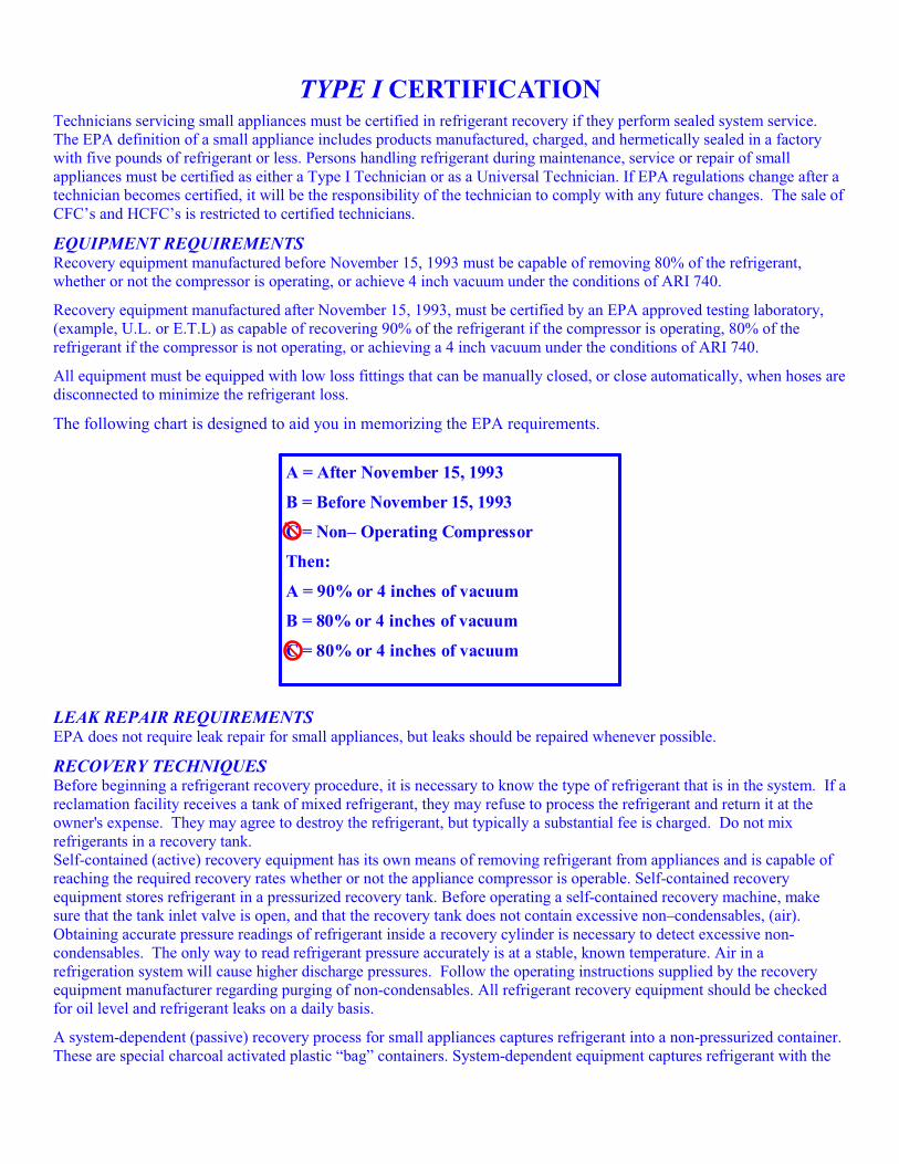
The following chart is designed to aid you in memorizing the EPA requirements.
A = After November 15, 1993
B = Before November 15, 1993
C = Non– Operating Compressor
Then:
A = 90% or 4 inches of vacuum
B = 80% or 4 inches of vacuum
C = 80% or 4 inches of vacuum
LEAK REPAIR REQUIREMENTS EPA does not require leak repair for small appliances, but leaks should be repaired whenever possible.
RECOVERY TECHNIQUES Before beginning a refrigerant recovery procedure, it is necessary to know the type of refrigerant that is in the system. If areclamation facility receives a tank of mixed refrigerant, they may refuse to process the refrigerant and return it at the owner's expense. They may agree to destroy the refrigerant, but typically a substantial fee is charged. Do not mix refrigerants in a recovery tank. Self-contained (active) recovery equipment has its own means of removing refrigerant from appliances and is capable of reaching the required recovery rates whether or not the appliance compressor is operable. Self-contained recovery equipment stores refrigerant in a pressurized recovery tank. Before operating a self-contained recovery machine, make sure that the tank inlet valve is open, and that the recovery tank does not contain excessive non–condensables, (air). Obtaining accurate pressure readings of refrigerant inside a recovery cylinder is necessary to detect excessive non-condensables. The only way to read refrigerant pressure accurately is at a stable, known temperature. Air in a refrigeration system will cause higher discharge pressures. Follow the operating instructions supplied by the recovery equipment manufacturer regarding purging of non-condensables. All refrigerant recovery equipment should be checked for oil level and refrigerant leaks on a daily basis.
A system-dependent (passive) recovery process for small appliances captures refrigerant into a non-pressurized container. These are special charcoal activated plastic “bag” containers. System-dependent equipment captures refrigerant with the
assistance of the appliance compressor, an external heat source, or a vacuum pump. A standard vacuum pump can only be used as a recovery device in combination with a non-pressurized container.
With system-dependant recovery equipment, some special procedures may be necessary, depending on the condition of the appliance. When using a system dependent recovery process on an appliance with an operating compressor, run the compressor and recover from the high side of the system. Usually, one access fitting on the high side will be sufficient to reach the required recovery rate, as the appliance compressor should be capable of pushing the refrigerant to the high side.
If the appliance has a non-operating compressor, access to both the low and high side of the system may be necessary. In order to achieve the required recovery efficiency, it will be necessary to take measures to help release trapped refrigerant from the compressor oil, (heat and tap the compressor several times and / or use a vacuum pump). Because appliances with non-operating compressors can not always achieve desired evacuation rates utilizing system-dependent recovery equipment, the EPA requires technicians to have at least one self-contained recovery device available at the shop to recover refrigerant from systems with non–operating compressors. The exception to this rule is technicians working on small appliances only. System dependent devices may only be used on appliances containing 15 lbs. of refrigerant or less. Small appliances are equipped with a straight piece of tubing that can be used to install a piercing type access fitting. When installing an access fitting onto a sealed system, the fitting should be leak tested before proceeding with recovery. It is generally recommended that solderless piercing type valves only be used on copper or aluminum tubing material. These fittings tend to leak over time and should not be left on an appliance as a permanent service fixture. After installing an access fitting, if you find that the system pressure is 0 psig., do not begin the recovery process. If the appliance is equipped with a defrost heater, such as in a domestic frost-free refrigerator, operating the defrost heater will help to vaporize any trapped liquid refrigerant and will speed the recovery process. If a strong odor is detected during the recovery process, a compressor burn-out has likely occurred. When recovering refrigerant from a system that experienced a compressor burn-out, watch for signs of contamination in the oil. After recovering refrigerant, if nitrogen is used to flush debris out of the system, the nitrogen may be vented.
Refrigerators built before 1950 may have used Methyl Formate, Methyl Chloride, or Sulfur Dioxide as refrigerant and should not be recovered with current recovery devices. Small appliances used in campers or other recreational vehicles may use refrigerants such as Ammonia, Hydrogen, or Water, and therefore should not be recovered using current recovery equipment.
When filling a graduated charging cylinder with a regulated refrigerant, the refrigerant vapor that is vented off the top of the cylinder must be recovered.
SAFETY & SHIPPING The safety and shipping requirements for TYPE I certification are covered in the CORE section of this manual.
TYPE II CERTIFICATION Technicians maintaining, servicing, repairing or disposing of high pressure or very high-pressure appliances, except small appliances and motor vehicle air conditioning systems, must be certified as a Type II Technician or a Universal Technician.
LEAK DETECTION After the installation of any type of system, the unit should first be pressurized with nitrogen (an inert gas) and leak checked. In order to determine the general area of a leak use an electronic or ultrasonic leak detector. Once the general area of the leak is located the use of soap bubbles will pinpoint the leak.
A refrigeration unit using an open compressor that has not been used in several months is likely to leak from the rotating shaft seal. During a visual inspection of any type of system, traces of oil are an indicator of a refrigerant leak. Excessivesuperheat, caused by a low refrigerant charge, is also an indication of a leak in a high-pressure system.
LEAK REPAIR REQUIREMENTS EPA regulations require that all comfort cooling appliances containing more than 50 lbs. of refrigerant MUST be repaired when the annual leak rate exceeds 15%.
EPA regulations require that all Commercial and Industrial Process Refrigeration containing more than 50 lbs. of refrigerant MUST be repaired when the annual leak rate exceeds 35%.
RECOVERY TECHNIQUES Proper recovery techniques begin with the use of appropriate recovery equipment that has been certified by an EPA approved laboratory (UL or ETL) to meet or exceed ARI standards.
Recovered refrigerants may contain acids, moisture, and oil. It is therefore necessary to frequently check and change both the oil and filter on a recycling machine. Both recycling and recovery equipment using hermetic compressors have the potential to overheat when drawing a deep vacuum because the unit relies on the flow of refrigerant through the compressor for cooling. Before using a recovery unit you should always check the service valve positions, the recovery units oil level, and evacuate and recover any remaining refrigerant from the unit’s receiver.
Technicians working with multiple refrigerants, before recovering and/or recycling a different refrigerant, must purge the recover/recycle equipment by recovering as much of the first refrigerant as possible, change the filter, and evacuate. The only exception to this rule is for technicians working with R-134A who must provide a special set of hoses, gauges, vacuum pump, recovery or recovery/recycling machine, and oil containers to be used with R-134A only.
Although recovering refrigerant in the vapor phase will minimize the loss of oil, recovering as much as possible in the liquid phase can reduce recovery time. The technician may choose to speed up the recovery process by packing the recovery cylinder in ice and/or applying heat to the appliance. After recovering liquid refrigerant, any remaining vapor is condensed by the recovery system.
When performing refrigerant system service on a unit that has a receiver/storage tank, refrigerant should be placed in the receiver. Refrigerant should be removed from the condenser outlet if the condenser is below the receiver. In a building that has an air-cooled condenser on the roof and an evaporator on the first floor, recovery should begin from the liquid line entering the evaporator. After recovery, refrigerant may be returned to the appliance from which it was removed or to another appliance owned by the same person without being recycled or reclaimed, unless the appliance is an MVAC (Motor Vehicle Air Conditioner) like appliance. The technician should always evacuate an empty recovery cylinder before transferring refrigerant to the cylinder. Quick couplers, self-sealing hoses, or hand valves should be used (as low loss fittings) to minimize refrigerant release when hoses are connected and disconnected.
RECOVERY REQUIREMENTS Refrigerant Recovery and/or Recycling equipment manufactured after November 15, 1993, must be certified and labeled by an EPA approved equipment testing organization to meet EPA standards.
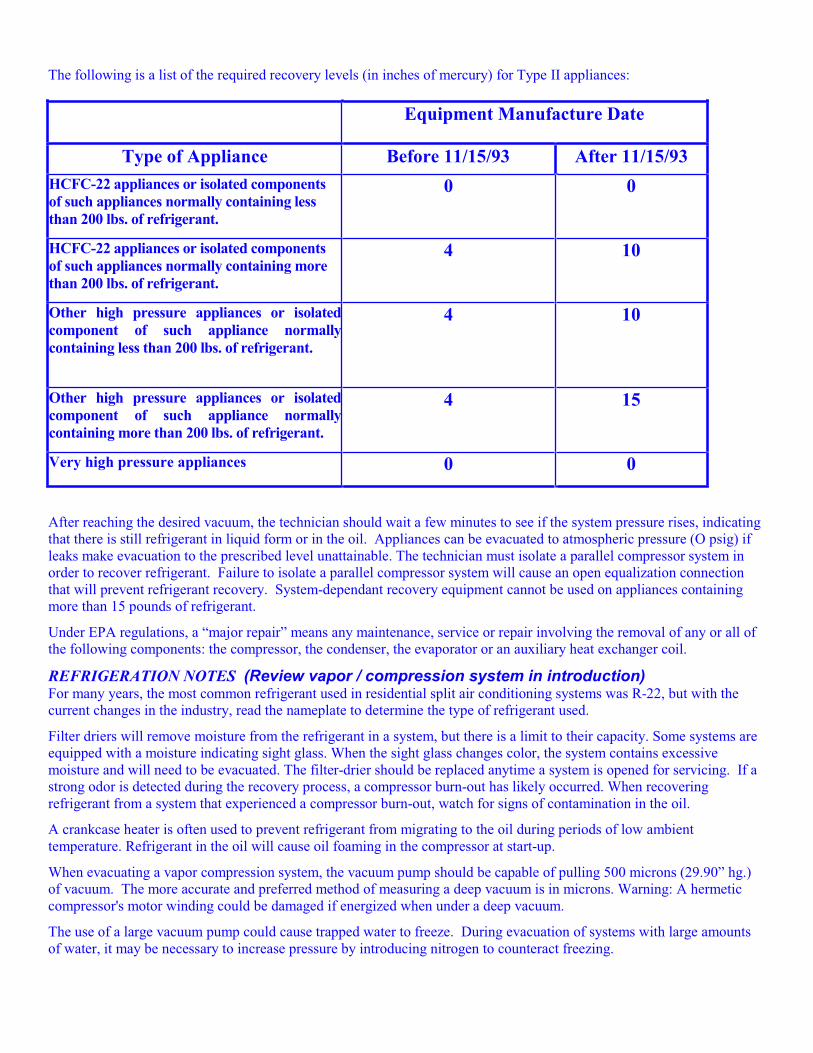
The following is a list of the required recovery levels (in inches of mercury) for Type II appliances:
Equipment Manufacture Date
Type of Appliance Before 11/15/93 After 11/15/93
HCFC-22 appliances or isolated components
of such appliances normally containing less
than 200 lbs. of refrigerant.
0 0
HCFC-22 appliances or isolated components
of such appliances normally containing more
than 200 lbs. of refrigerant.
4 10
Other high pressure appliances or isolated
component of such appliance normally
containing less than 200 lbs. of refrigerant.
4 10
Other high pressure appliances or isolated
component of such appliance normally
containing more than 200 lbs. of refrigerant.
4 15
Very high pressure appliances 0 0
After reaching the desired vacuum, the technician should wait a few minutes to see if the system pressure rises, indicating that there is still refrigerant in liquid form or in the oil. Appliances can be evacuated to atmospheric pressure (O psig) if leaks make evacuation to the prescribed level unattainable. The technician must isolate a parallel compressor system in order to recover refrigerant. Failure to isolate a parallel compressor system will cause an open equalization connection that will prevent refrigerant recovery. System-dependant recovery equipment cannot be used on appliances containing more than 15 pounds of refrigerant.
Under EPA regulations, a “major repair” means any maintenance, service or repair involving the removal of any or all of the following components: the compressor, the condenser, the evaporator or an auxiliary heat exchanger coil.
REFRIGERATION NOTES (Review vapor / compression system in introduction) For many years, the most common refrigerant used in residential split air conditioning systems was R-22, but with the current changes in the industry, read the nameplate to determine the type of refrigerant used.
Filter driers will remove moisture from the refrigerant in a system, but there is a limit to their capacity. Some systems are equipped with a moisture indicating sight glass. When the sight glass changes color, the system contains excessive moisture and will need to be evacuated. The filter-drier should be replaced anytime a system is opened for servicing. If a strong odor is detected during the recovery process, a compressor burn-out has likely occurred. When recovering refrigerant from a system that experienced a compressor burn-out, watch for signs of contamination in the oil.
A crankcase heater is often used to prevent refrigerant from migrating to the oil during periods of low ambient temperature. Refrigerant in the oil will cause oil foaming in the compressor at start-up.
When evacuating a vapor compression system, the vacuum pump should be capable of pulling 500 microns (29.90” hg.) of vacuum. The more accurate and preferred method of measuring a deep vacuum is in microns. Warning: A hermetic compressor's motor winding could be damaged if energized when under a deep vacuum.
The use of a large vacuum pump could cause trapped water to freeze. During evacuation of systems with large amounts of water, it may be necessary to increase pressure by introducing nitrogen to counteract freezing.

The source of most non-condensables is air. Non-condensables will cause higher discharge pressures.
Where there is a risk of freezing, liquid charging of an R-12 refrigeration system should begin with vapor from a vacuum level to a pressure of approximately 33 psig. Followed by a liquid charge through the liquid-line service valve. This is also the proper method to charge a system that contains a large quantity of refrigerant.
SAFETY (Additional Safety and shipping information is covered in the core section of this manual.)ASHRAE standard 15 requires a refrigerant sensor that will sound an alarm and automatically start a ventilation system in occupied equipment rooms where refrigerant from a leak will concentrate.
Refrigerants CFC-12, CFC-11, and HFC-134a are categorized as A-1.
All refrigeration systems must be protected by a pressure relief valve (s) (must not be installed in series).
NEVER energize a reciprocating compressor if the discharge service valve is closed.
TYPE III CERTIFICATION Technicians maintaining, servicing, repairing or disposing of low-pressure appliances must be certified as a Type III Technician or a Universal Technician.
As of November 14, 1994, the sale of CFC and HCFC refrigerants is restricted to certified technicians.
NOTE: If EPA regulations change after the technician is certified, it will be the technician's responsibility to comply with any future changes.
LEAK DETECTION Because a low-pressure system operates below atmospheric pressure (in a vacuum), leaks in the gaskets or fittings will cause air and moisture to enter the system.
The most efficient method of leak checking a charged low-pressure refrigeration unit is to pressurize the system by the use of controlled hot water or heater blankets. When controlled hot water or heater blankets are not feasible, use nitrogen to increase pressure. When pressurizing a system, do not exceed 10 psig. Exceeding 10 psig can cause the rupture disc to fail. When leak testing a water box, be certain the water has been removed before placing the leak detector probe through the drain valve. To leak test a tube, use a hydrostatic tube test kit. Systems with open drive compressors are prone to leaks at the shaft seal.
Controlled hot water can be used to pressurize a system for the purpose of opening the system for a non-major repair. Under EPA regulations, a “major repair” means any maintenance, service or repair involving the removal of any or all of the following components: the compressor, the condenser, the evaporator or any auxiliary heat exchanger coil.
LEAK REPAIR REQUIREMENTS EPA regulations require that all comfort cooling appliances containing more than 50 lbs. of refrigerant be repaired when the annual leak rate exceeds 15%.
EPA regulations require that all commercial and industrial process refrigeration containing more than 50 lbs. of refrigerant be repaired when the annual leak rate exceeds 35%.
(See Type II for definition of commercial and industrial appliances.)
RECOVERY TECHNIQUES A recovery unit's high pressure cut-out is set for 10 psig when evacuating the refrigerant from a low-pressure chiller and a rupture disc on a low-pressure recovery vessel relieves at 15 psig.
Refrigerant recovery from a system using R-11 or R-123 starts with liquid removal and is followed by vapor recovery. A substantial amount of vapor will remain in the appliance after all liquid is removed. For instance, an average 350 ton R-11 chiller at 0 psig still contains 100 lbs. of vapor after all the liquid has been removed.
Water must be circulated through the tubes when evacuating refrigerant in order to prevent freezing the water. Most low-pressure recovery machines utilize a water-cooled condenser that is connected to the municipal water supply. When recovering refrigerant, the system water pumps, the recovery compressor, and the recovery condenser water should all be on. If a chiller is suspected of tube leaks, the water sides of the evaporator and condenser should be drained prior to recovering the refrigerant.
The ASHRAE Guideline 3-1996 states that if the pressure in a system rises from 1 mm Hg to a level above 2.5 mm Hg during vacuum testing, the system should be leak checked.
A temperature of 130° F should be attained when removing oil from a low-pressure system. Fewer refrigerants is contained in the oil at this higher temperature.
RECHARGING TECHNIQUES Refrigerant is added through the lowest access point on the system, the evaporator charging valve. However, introducing liquid refrigerant into a deep vacuum will cause the refrigerant to boil and may lower temperatures enough to freeze water in the tubes. Therefore, initial charging is in the vapor phase. Before charging with liquid, an R-11 refrigeration system
requires a vapor pressure of 16.9” hg. vacuum, or a saturation temperature of 36° F.
RECOVERY REQUIREMENTS Refrigerant Recovery and/or Recycling equipment manufactured after November 15, 1993, must be certified and labeled by an EPA approved equipment testing organization to meet EPA standards. All equipment must have low loss fittings to minimize refrigerant loss when hoses are disconnected.
The following is a list of the required levels of evacuation for Low Pressure appliances:
Using recovery or recycling equipment manufactured or imported before Nov. 15, 1993
25 inches Hg
Using recovery or recycling equipment manufactured or imported on or after Nov. 15, 1993
25 mm Hg absolute
Once the required vacuum has been achieved, the technician should wait for a few minutes and monitor the system pressure. If the pressure rises, indicating that there is refrigerant remaining in the system, recovery must be repeated. When leaks in an appliance make evacuation to the prescribed level unattainable, the appliance should be evacuated to the lowest attainable level prior to a major repair.
REFRIGERATION NOTES (Review vapor / compression system in introduction) The use of a large vacuum pump could cause trapped water to freeze. During evacuation of systems with large amounts of water, it may be necessary to increase pressure by introducing nitrogen to counteract freezing.
If a strong odor is detected during the recovery process, a compressor burn-out has likely occurred. When recovering refrigerant from a system that experienced a compressor burn-out, watch for signs of contamination in the oil.
Because chillers using refrigerants such as CFC-11 and HCFC-123 operate below atmospheric pressure, they require a purge unit. The primary purpose of a purge unit is to remove non-condensables from the system. A centrifugal chiller's purge condensing unit takes its suction from the top of the condenser, removes air and other non-condensables from the system, and returns refrigerant to the evaporator. Although a high efficiency purge unit discharges a low percentage of refrigerant with the air they remove, frequent purging and subsequent refrigerant loss can indicate that a leak is allowing air into the system. High discharge pressure is also an indication of air in the system Excessive moisture collection in the purge unit can indicate tube leakage.
To protect the system from over-pressurization, low-pressure chillers typically use a rupture disc mounted on the evaporator housing. The typical design burst pressure for a rupture disc is 15 psig.
SAFETY (Additional Safety and shipping information is covered in the core section of this manual.)ASHRAE standard 15 requires a refrigerant monitor that will sound an alarm and automatically start a ventilation system in equipment rooms before the refrigerant concentration reaches the TLV-TWA, (threshold limit value — time weighted average).
A refrigerant monitor is required for all ASHRAE refrigerant safety groups.
CFC-12, CFC-11, and HFC-134a are code grouped as A-1. R-123 is code grouped as B-1.
All refrigeration systems must be protected by a pressure relief valve (s) (must not be installed in series).
Additional Safety and shipping information is covered in the core section of this manual