UNIVERSAL SCAN ENGINE DEVELOPER’S · PDF fileii UNIVERSAL SCAN ENGINE DEVELOPER’S...
48
UNIVERSAL SCAN ENGINE DEVELOPER’S INSTALLATION GUIDE
Transcript of UNIVERSAL SCAN ENGINE DEVELOPER’S · PDF fileii UNIVERSAL SCAN ENGINE DEVELOPER’S...

UNIVERSAL SCAN ENGINE DEVELOPER’S INSTALLATION GUIDE


UNIVERSAL SCAN ENGINE DEVELOPER’S KITINSTALLATION GUIDE
72E-59636-05 Rev. A
May 2015

ii UNIVERSAL SCAN ENGINE DEVELOPER’S KIT INSTALLATION GUIDE
No part of this publication may be reproduced or used in any form, or by any electrical or mechanical means, without permission in writing from Zebra. This includes electronic or mechanical means, such as photocopying, recording, or information storage and retrieval systems. The material in this manual is subject to change without notice.
The software is provided strictly on an “as is” basis. All software, including firmware, furnished to the user is on a licensed basis. Zebra grants to the user a non-transferable and non-exclusive license to use each software or firmware program delivered hereunder (licensed program). Except as noted below, such license may not be assigned, sublicensed, or otherwise transferred by the user without prior written consent of Zebra. No right to copy a licensed program in whole or in part is granted, except as permitted under copyright law. The user shall not modify, merge, or incorporate any form or portion of a licensed program with other program material, create a derivative work from a licensed program, or use a licensed program in a network without written permission from Zebra. The user agrees to maintain Zebra’s copyright notice on the licensed programs delivered hereunder, and to include the same on any authorized copies it makes, in whole or in part. The user agrees not to decompile, disassemble, decode, or reverse engineer any licensed program delivered to the user or any portion thereof.
Zebra reserves the right to make changes to any software or product to improve reliability, function, or design.
Zebra does not assume any product liability arising out of, or in connection with, the application or use of any product, circuit, or application described herein.
No license is granted, either expressly or by implication, estoppel, or otherwise under any Zebra Technologies Corporation, intellectual property rights. An implied license only exists for equipment, circuits, and subsystems contained in Zebra products.
WarrantyFor the complete Zebra hardware product warranty statement, go to:
http://www.zebra.com/warranty.
iii
Revision HistoryChanges to the original guide are listed below:
Change Date Description
-01 Rev A 7/2011 New Motorola Solutions branding; updated engines: removed end-of-life engines; added new engines and relevant data; updated drawings.
-05 Rev A 5/2015 Zebra Re-branding

iv UNIVERSAL SCAN ENGINE DEVELOPER’S KIT INSTALLATION GUIDE

Warranty ......................................................................................................................................... iiRevision History .............................................................................................................................. iii
About This GuideIntroduction ..................................................................................................................................... viiChapter Descriptions ...................................................................................................................... viiNotational Conventions................................................................................................................... viiiRelated Documents ........................................................................................................................ viiiService Information ......................................................................................................................... ix
Chapter 1: GETTING STARTEDIntroduction .................................................................................................................................... 1-1Unpacking ...................................................................................................................................... 1-1UDK Contents ................................................................................................................................ 1-2Mounting Considerations ............................................................................................................... 1-3
SE655, SE955, SE965, SE1524 .............................................................................................. 1-3SE3300/PL3307, SE4500/PL4507, SE6700/PL6707 .............................................................. 1-3
Simple Serial Interface ................................................................................................................... 1-3Symbol Native Application Programming Interface (SNAPI) ......................................................... 1-4Development Board ....................................................................................................................... 1-4
Quick Installation ...................................................................................................................... 1-4
Chapter 2: ELECTRICAL CONSIDERATIONSIntroduction .................................................................................................................................... 2-1Board Functional Descriptions ....................................................................................................... 2-1Power Configuration - Block 1 ....................................................................................................... 2-2USB Power Selection - Block 2 (Imager Engine Systems) ............................................................ 2-4Host Communication Configuration - Block 3 (Imager Engine Systems) ....................................... 2-5Signal Breakout - Block 4 ............................................................................................................... 2-6External Illumination Interface - Block 5 (Imager Engine Systems) ............................................... 2-7Download Button - Block 6 ............................................................................................................. 2-7
TABLE OF CONTENTS

vi UNIVERSAL SCAN ENGINE DEVELOPER’S KIT INSTALLATION GUIDE
RS-232 Circuitry - Block 7 ............................................................................................................. 2-8User Interface Circuitry - Block 8 ................................................................................................... 2-8Engine Mounting Holes - Block 9 ................................................................................................... 2-9
Appendix A: REFERENCE SCHEMATICUDK Reference Schematic ............................................................................................................ A-1
Index
Glossary

ABOUT THIS GUIDE
IntroductionThe Universal Scan Engine Developer’s Kit Installation Guide provides general instructions for installing and configuring the Universal Development board.
For the latest Simple Serial Interface (SSI) Software Developer’s Kit (SDK) and Symbol Native API (SNAPI) SDK, visit: http://www.zebra.com/support/product/DKSE-2000.html.
Chapter DescriptionsThis guide includes the following topics:
• Chapter 1, GETTING STARTED provides an overview of the Universal Scan Engine Developers Kit, including descriptions of SSI and SNAPI, engine mounting considerations, and general installation instructions.
• Chapter 2, ELECTRICAL CONSIDERATIONS describes the components of the development board.
• Appendix A, REFERENCE SCHEMATIC provides schematic drawings of the development board kit.

viii UNIVERSAL SCAN ENGINE DEVELOPER’S KIT INSTALLATION GUIDE
Notational ConventionsThis document uses the following conventions:
• Italics are used to highlight chapters and sections in this and related documents
• bullets (•) indicate:• Action items• Lists of alternatives• Lists of required steps that are not necessarily sequential
• Sequential lists (e.g., those that describe step-by-step procedures) appear as numbered lists.
Related Documents• Simple Serial Interface (SSI) SDK
• Simple Serial Interface (SSI) Software Developer’s Kit Programmer Guide, p/n 72E-59860-xx
• Symbol Native API (SNAPI) SDK
• Symbol Native Application Programming Interface (SNAPI) Programmer Guide, p/n 72E-71370-xx
For the latest version of software and guides, visit: http://www.zebra.com/support/product/DKSE-2000.html.
NOTE This symbol indicates something of special interest or importance to the reader. Failure to read the note will not result in physical harm to the reader, equipment or data.
CAUTION This symbol indicates that if this information is ignored, the possibility of data or material damage may occur.
WARNING! This symbol indicates that if this information is ignored the possibility that serious personal injury may occur.

About This Guide ix
Service InformationIf you have a problem with your equipment, contact Zebra Support for your region. Contact information is available at: http://www.zebra.com/support.
When contacting Mobility, please have the following information available:
• Serial number of the unit
• Model number or product name
• Software type and version number.
Zebra responds to calls by E-mail, telephone or fax within the time limits set forth in support agreements.
If your problem cannot be solved by Zebra Support, you may need to return your equipment for servicing and will be given specific directions. Zebra is not responsible for any damages incurred during shipment if the approved shipping container is not used. Shipping the units improperly can possibly void the warranty.
If you purchased your business product from a Zebra business partner, contact that business partner for support.

x UNIVERSAL SCAN ENGINE DEVELOPER’S KIT INSTALLATION GUIDE

CHAPTER 1 GETTING STARTED
IntroductionThe Universal Scan Engine Developer’s Kit (UDK), p/n DKSE-2000-000R, provides the software and hardware tools needed to design and test an embedded scan engine application before integration into a host device.
This guide explains how to install and configure the scan engine. The SSI Software Developer’s Kit Programmer Guide (p/n 72E-59860-xx) explains how to use the Simple Serial Interface (SSI) UDK. This UDK is a complete package that enables users to benefit from Zebra's SSI protocol used in all of our decoded and imager engine offerings: SE6700/PL6707, SE3300/PL3307, SE4500/PL4507, and SE655, and laser-based engines such as the SE955, SE965, SE1223 and SE1524.
Imager engine systems also support the SNAPI protocol over USB. The kit consists of a developer's board, interface cables, and 5 V universal power supply. Use the link below to download the latest versions of the SSI Software Developer’s Kit and SNAPI Software Developer’s Kit.
The UDK offers many user-friendly features and allows developers to use one development platform to work with all Zebra's decoded engines, so the development board can be re-used for all decoded engine integration projects.
UnpackingRemove the material from its packing and inspect for damage. If the material was damaged in transit, contact Zebra Support. See Service Information on page ix for information. KEEP THE PACKING. It is the approved shipping container; use this to return the equipment for servicing.
NOTE Visit: http://www.zebra.com/support/product/DKSE-2000.html for the latest documentation and downloads.

1 - 2 UNIVERSAL SCAN ENGINE DEVELOPER’S KIT INSTALLATION GUIDE
UDK ContentsTable 1-1 lists the material included in the UDK box.
Table 1-1 DKSE-2000-000R Contents
Item Part Number Quantity
RS-232 Cable Assembly 50-16000-410 1
5.2VDC Power Supply 50-14000-058R 1
UDK Decoded Circuit Board 60-151670-01 1
Berg Header Jumpers 50-02100-1105 40
12 Pin Fanout Flex for SE955, SE965, SE1524 15-81378-01 1
12 Pin 10 in. Flex for SE935, SE965, SE1524 50-16000-134R 1
30 Pin Flex for PL3307/4507//6707 to Host 50-16000-623Note: White Flex; part number does not appear on Flex.
1
SE655 Flex 15-141354-01 1
SE4500 21 Flex 15-113896-01 1
SE655 10 Pin Fanout 15-10414-01 1
Screw: #0 - 48 x 0.19 50-12809-068B 6
Screw: #2 - 32 x 0.19 50-12809-001 4
Screw: M2 - 0.4mm x 4mm L 50-12854-0040L 4
Screw: M1.6 - 0.35mm x 6mm L 50-12800-1190 6
Screw: M1.6 - 0.35mm x 4mm L 50-12800-944 4
Nut: M1.6 50-12800-1191 6
Spacers for PL Decoder Boards 50-12800-1304 6
Standoffs 50-01400-408 4
DKSE2000 China RoHS Insert 72-96027-0336 1
DKSE2000 Download Information 72-152004-01 1
GETTING STARTED 1 - 3
Mounting Considerations
SE655, SE955, SE965, SE1524
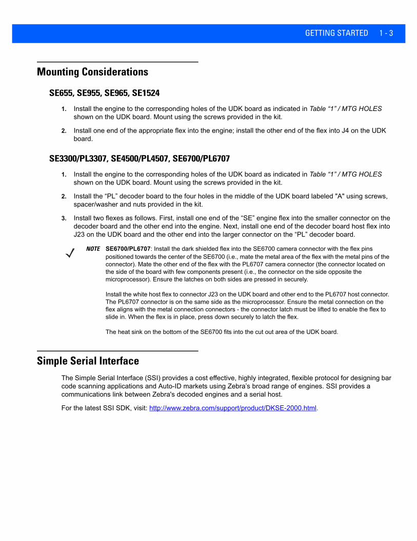
1. Install the engine to the corresponding holes of the UDK board as indicated in Table “1” / MTG HOLES shown on the UDK board. Mount using the screws provided in the kit.
2. Install one end of the appropriate flex into the engine; install the other end of the flex into J4 on the UDK board.
SE3300/PL3307, SE4500/PL4507, SE6700/PL6707
1. Install the engine to the corresponding holes of the UDK board as indicated in Table “1” / MTG HOLES shown on the UDK board. Mount using the screws provided in the kit.
2. Install the “PL” decoder board to the four holes in the middle of the UDK board labeled "A" using screws, spacer/washer and nuts provided in the kit.
3. Install two flexes as follows. First, install one end of the “SE” engine flex into the smaller connector on the decoder board and the other end into the engine. Next, install one end of the decoder board host flex into J23 on the UDK board and the other end into the larger connector on the “PL” decoder board.
Simple Serial InterfaceThe Simple Serial Interface (SSI) provides a cost effective, highly integrated, flexible protocol for designing bar code scanning applications and Auto-ID markets using Zebra’s broad range of engines. SSI provides a communications link between Zebra's decoded engines and a serial host.
For the latest SSI SDK, visit: http://www.zebra.com/support/product/DKSE-2000.html.
NOTE SE6700/PL6707: Install the dark shielded flex into the SE6700 camera connector with the flex pins positioned towards the center of the SE6700 (i.e., mate the metal area of the flex with the metal pins of the connector). Mate the other end of the flex with the PL6707 camera connector (the connector located on the side of the board with few components present (i.e., the connector on the side opposite the microprocessor). Ensure the latches on both sides are pressed in securely.
Install the white host flex to connector J23 on the UDK board and other end to the PL6707 host connector. The PL6707 connector is on the same side as the microprocessor. Ensure the metal connection on the flex aligns with the metal connection connectors - the connector latch must be lifted to enable the flex to slide in. When the flex is in place, press down securely to latch the flex.
The heat sink on the bottom of the SE6700 fits into the cut out area of the UDK board.

1 - 4 UNIVERSAL SCAN ENGINE DEVELOPER’S KIT INSTALLATION GUIDE
Symbol Native Application Programming Interface (SNAPI)The Symbol Native Application Programming Interface (SNAPI) is a development library used to implement USB communication between a Zebra decoder and a Windows 98/2000/XP host. SNAPI is a transaction-based protocol that enables communication with SNAPI devices over USB. The SNAPI DLL implements:
• USB HID communications
• SNAPI USB imaging driver communications
• SNAPI message building
• SNAPI protocol handling for a communications link between Zebra scanners and a Windows host.
For the lastest SNAPI SDK, visit: http://www.zebra.com/support/product/DKSE-2000.html.
Development BoardThe UDK PCB accommodates multiple scope probes, debug aids, and provides a large work area for developers. The board also has many ground and VCC posts so users can easily probe and simulate logic levels on scanner lines.
Since the board supports all decoded engines, instructions for configuring the board to an engine is silk-screened on the board.
Quick Installation
The following installation procedure is typical for most development applications, and does not address all board features. For detailed debugging and testing, see the appropriate sections of this guide.
1. Install the four white PCB standoffs (included in the kit) by snapping them into the corresponding holes in the corners of the UDK board.
2. Mount the engine on the development board. See UDK Contents on page 1-2 and Mounting Considerations on page 1-3 for assistance.
3. Determine the voltage requirements for the engine. See Table “1” in Figure 1-1 on page 1-5, which is silk-screened on the board, or see Table 2-1 on page 2-3.
4. Configure the power supply on the board to the correct output voltage determined in Step 3 by setting the jumpers on header J29 as specified in Power Configuration - Block 1 on page 2-2.
5. Add a jumper to the appropriate header that connects the board voltage to the engine. See Table 2-1 on page 2-3.
6. If using the SE4400/PL4407, SE4500/PL4507, or SE6700/PL6707, configure the System Configuration Bits to reflect the proper communication bus to the host. See Host Communication Configuration - Block 3 (Imager Engine Systems) on page 2-5.
7. Install the 13 Break Out Header jumpers on headers J17, J18, J14, and J21. See Signal Breakout - Block 4 on page 2-6.
8. Connect the interface cable between the development board and the host system.
9. Connect the DC power cord between the power supply and connector J1 on the development board.
NOTE Not all connectors provided on the board are used with every engine.
CAUTION Be sure to set the voltage on the board to the proper voltage for the engine. Applying incorrect voltage can destroy the engine.

GETTING STARTED 1 - 5
10. Connect the AC cord between the power supply and an AC outlet.
Figure 1-1 Universal Development Board Assembly
SE955-3VSE955-5VSE965SE1524SE3300/PL3307SE4500/PL4507SE6700/PL6707
PL3307PL4507PL6707
SE655/955/965/1524
SE6553.3V3.3V
3.3V3.3V3.3V3.3V3.3V
FDDDBC/AE/AG/A
5V
C
E
DB
G
D/E
GBB
FF

1 - 6 UNIVERSAL SCAN ENGINE DEVELOPER’S KIT INSTALLATION GUIDE

CHAPTER 2 ELECTRICAL CONSIDERATIONS
IntroductionThe UDK is a universal development board for all Zebra data capture engines. The board supports the decoded imaging solutions SE6700/PL6707, SE3300/PL3307, SE4500/PL4507, and SE655, and laser-based engines such as the SE955, SE965, SE1223 and SE1524. The board includes a detailed silk screen to assist in installation and use of the engines during development. The following section describes each part of the board.
Board Functional DescriptionsThe following sections detail the specific components on the board. Figure 1-1 on page 1-5 indicates each component or group of components on the assembly in outlined areas, by block number.

2 - 2 UNIVERSAL SCAN ENGINE DEVELOPER’S KIT INSTALLATION GUIDE
Power Configuration - Block 1Block one (1) represents board power configuration and selection. Since the UDK board supports many decoded engines, configure the power supplied to the engine to the voltage specified in Table 1, which is silk-screened on the PCB. To set engine power, populate jumpers on J29 according to the figures silk-screened on the PCB in the section labeled Board Power Selection. The electrical schematic and jumper configurations are shown in Figure 2-1 and Figure 2-2. For the selected voltage, attach a jumper to J29 where a rectangle is drawn.
Figure 2-1 Electrical Schematic
Figure 2-2 Jumper Configurations for Power
In addition to configuring the voltage to the engine, populate a jumper to supply power to the particular engine being used. Populate the jumper on the appropriate power enable header according to Table 2-1. As an alternative to the jumper, place an ammeter across this power enable header to measure the current draw of the engine.
NOTE For the SE4500/PL4507, choose 3.3V settings on J29.
ELECTRICAL CONSIDERATIONS 2 - 3
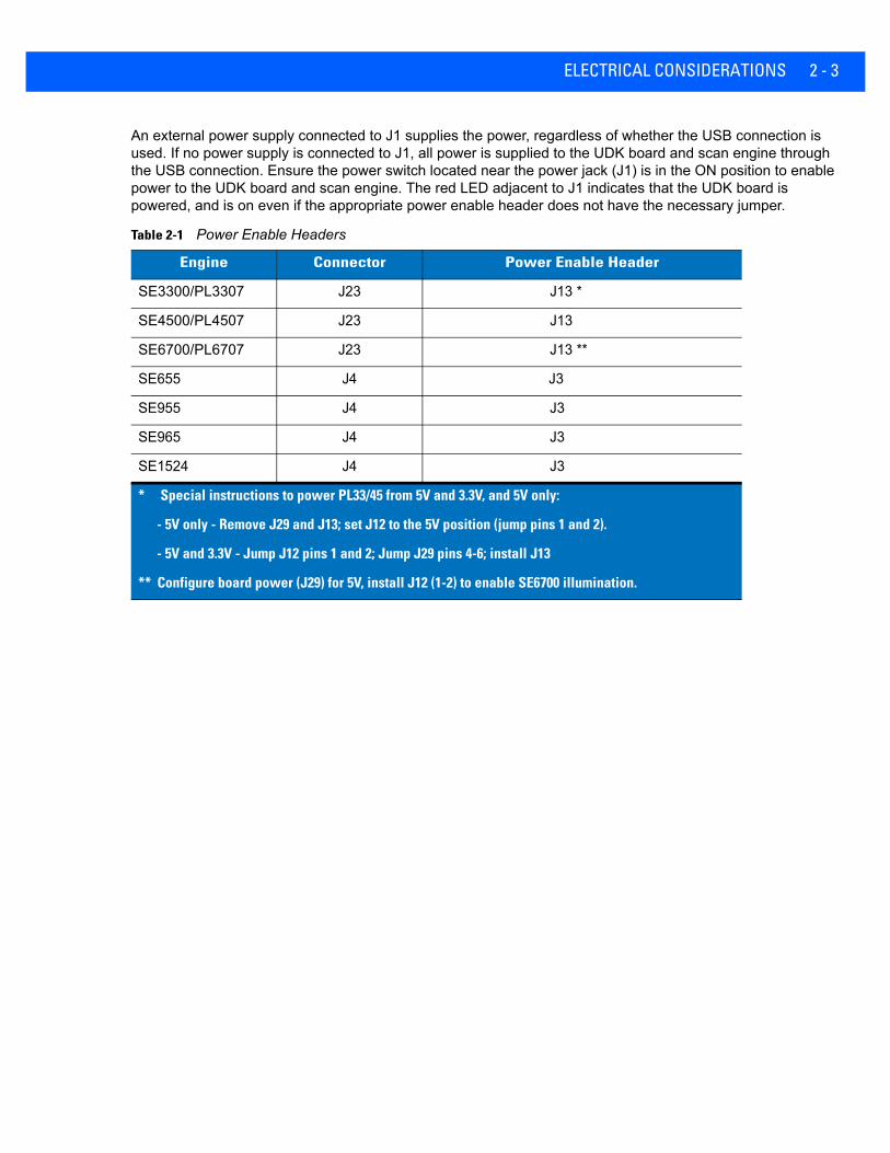
An external power supply connected to J1 supplies the power, regardless of whether the USB connection is used. If no power supply is connected to J1, all power is supplied to the UDK board and scan engine through the USB connection. Ensure the power switch located near the power jack (J1) is in the ON position to enable power to the UDK board and scan engine. The red LED adjacent to J1 indicates that the UDK board is powered, and is on even if the appropriate power enable header does not have the necessary jumper.
Table 2-1 Power Enable Headers
Engine Connector Power Enable Header
SE3300/PL3307 J23 J13 *
SE4500/PL4507 J23 J13
SE6700/PL6707 J23 J13 **
SE655 J4 J3
SE955 J4 J3
SE965 J4 J3
SE1524 J4 J3
* Special instructions to power PL33/45 from 5V and 3.3V, and 5V only:
- 5V only - Remove J29 and J13; set J12 to the 5V position (jump pins 1 and 2).
- 5V and 3.3V - Jump J12 pins 1 and 2; Jump J29 pins 4-6; install J13
** Configure board power (J29) for 5V, install J12 (1-2) to enable SE6700 illumination.

2 - 4 UNIVERSAL SCAN ENGINE DEVELOPER’S KIT INSTALLATION GUIDE
USB Power Selection - Block 2 (Imager Engine Systems)
The jumper pad in Figure 2-3 provides three power options (indicated on the silk screen) for the PL4407, PL4507, and PL6707.
USB subsystem:
• Supply the USB system with +5 V from the DC power jack (J1). To do this (based on the silk screen), install the jumper on J12 pins 1-2.
• Supply the USB system with +5 V from the USB bus via connector J25. To do this (based on the silk screen), install the jumper on J12 pins 3-4. DO NOT install the power supply in J1; the power switch (S4) still controls the power to the board.
• For the PL4407 and PL6707 only: Supply the USB system with +3.3 V. To do this (based on the silk screen), install the jumper on J12 pins 7-8, then drive 3.3 V in terminal T5 located next to J12. Ensure the external supply is also referenced to the board ground which can be located on J10 or any of the four black test posts (T1, T2, T3, and T7).
Figure 2-3 Jumper Configurations for USB Power
NOTE Not all Zebra engines support the USB interface.
Optional 3.3 V Input for PL4407and PL6707 USB

ELECTRICAL CONSIDERATIONS 2 - 5
Host Communication Configuration - Block 3 (Imager Engine Systems)The jumper pad in Figure 2-4 sets the system configuration bits, which determine the type of communication between the PL4407/PL6707 and a host. Based on the silk screen the following jumper configurations set the desired communication method:
Figure 2-4 Jumper Configurations for Host Communication
Table 2-2 Jumper Settings for Host Communication
Communication Type Jumper Settings for J7
RS-232 Install jumper on pins 1-2 and 3-4
USB Install jumper on pins 1-2
HSSI Install jumper on pins 3-4
NOTE For PL4507 configuration, refer to the Symbol PL4507 Decoder Integration Guide, p/n 72E-116649-xx.Installing a jumper represents a value of 0; omitting a jumper represents a value of 1. Pins 1 - 2 correspond to HOST_SYS_CFG1; pins 3 - 4 correspond to HOST_SYS_CFG0.

2 - 6 UNIVERSAL SCAN ENGINE DEVELOPER’S KIT INSTALLATION GUIDE
Signal Breakout - Block 4Block four (4) contains multiple jumper pads including J9, J19, J26, J27, J11, J17, J18, J14, and J21 shown in Figure 2-5. These jumpers provide test points for probing all logic signals to and from the engine. This block also functions as a break-out pad so jumpers can be removed and the signal between the engine and the host can be isolated and driven externally by another source.
Figure 2-5 Signal Breakout Jumpers
The break out pads are the dual row headers J17, J18, J14, and J21 from left to right as they appear on the board and in Figure 2-5. The signals mapped to these headers are silk screened between these headers and the single row headers J9, J27, J26, J19, and J20. The single row headers are test points for probing, and are connected directly to the engine signals that propagate from J23/J4/J8. Install the jumpers on the dual row headers to connect these signals to the rest of the board including the board connectors, LEDs, and beeper. Remove the jumpers on the dual row headers to break this connection and access either node of the signal.
ELECTRICAL CONSIDERATIONS 2 - 7
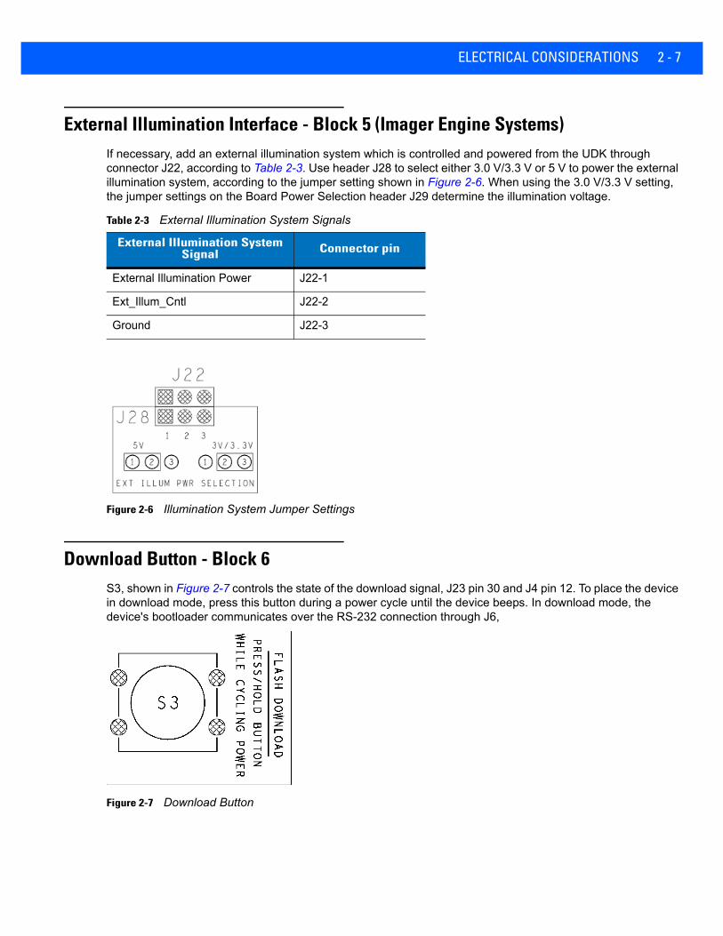
External Illumination Interface - Block 5 (Imager Engine Systems)If necessary, add an external illumination system which is controlled and powered from the UDK through connector J22, according to Table 2-3. Use header J28 to select either 3.0 V/3.3 V or 5 V to power the external illumination system, according to the jumper setting shown in Figure 2-6. When using the 3.0 V/3.3 V setting, the jumper settings on the Board Power Selection header J29 determine the illumination voltage.
Figure 2-6 Illumination System Jumper Settings
Download Button - Block 6S3, shown in Figure 2-7 controls the state of the download signal, J23 pin 30 and J4 pin 12. To place the device in download mode, press this button during a power cycle until the device beeps. In download mode, the device's bootloader communicates over the RS-232 connection through J6,
Figure 2-7 Download Button
Table 2-3 External Illumination System Signals
External Illumination System Signal Connector pin
External Illumination Power J22-1
Ext_Illum_Cntl J22-2
Ground J22-3

2 - 8 UNIVERSAL SCAN ENGINE DEVELOPER’S KIT INSTALLATION GUIDE
RS-232 Circuitry - Block 7The circuitry in block seven (7) shown in Figure 2-8 is composed of the RS-232 DB-9 connector (J6), a 1 Mbps RS-232 transceiver (U1), and four LEDs that provide visual status of the RTS, CTS, TXD, and RXD signals between the host and the engine.
Figure 2-8 RS-232 Subsystem Circuitry
User Interface Circuitry - Block 8Block eight (8) contains the Trigger button, Aim/Wake button, Decode LED and Power Down LED. Table 2-4 details each of these components.
Table 2-4 Block Eight Components
Component Description
Trigger Button (S2) This button controls the polarity of the trigger signal, J23 pin 19 and J4 pin 1, to the engine. When pressed it forces a trigger into the engine, starting a decode session. It also wakes the engine from low power mode.
Aim/Wake Button (S1) This dual-purpose button drives the AIM/WAKE* signal J23 pin 20 and J4 pin 2, to the engine. When the engine is in low power mode, the button drives the wake signal into the engine to force it into normal power mode. If the engine is in normal power mode, the button drives the aim signal which turns on the aiming pattern when the engine is in the correct mode. Refer to the PL4407 Integration Guide for more details.
Power Down LED This LED is tied to the PWRDWN* signal, J23 pin 23 and J4 pin 5. The engine illuminates this to indicate it is low power mode.
Decode LED This LED is tied to the DLED* signal, J23 pin 19 and J4 pin 3. The engine illuminates this to indicate a good decode.

ELECTRICAL CONSIDERATIONS 2 - 9
Engine Mounting Holes - Block 9Block nine (9) contains the mounting holes for all supported data capture engines. Refer to the silk screen on the board for mounting hole instructions.

2 - 10 UNIVERSAL SCAN ENGINE DEVELOPER’S KIT INSTALLATION GUIDE

APPENDIX A REFERENCE SCHEMATIC
UDK Reference Schematic
Figure A-1 UDK Reference Schematic
LP3855
U20TO263-5
C5147UF
+
1.47KR24110.0UFC25
VCC_5 VCC_3
0
R10
1KR17
2200PF
C3221
R1
-S2HDR
J29-
J29
-
J29
-
J29-
J29
-
J29
VCC VCC_3VCC_5
453V/3.3V
VCC
FOR 3VINSTALLFOR 3VFOR 3V
4 5V
5V CONFIGURATION 3.3V CONFIGURATION
6
213
3V CONFIGURATION
BOARD POWER SELECTION
5V5
3V/3.3V6
31 2
VCC5V6543
1
INSTALL
2
VCC
3V/3.3V
3V/3.3V POWER SUPPLY
INSTALL
SD
VOUTVIN
FB
GND MTH
642
531
42
1
MTH3
5X7R121010V20% 1%
0805
1% 10V
S2
S1
S3
FLASH DOWNLOAD SECTION
PRESS AND HOLD BUTTON WHILE RECYCLING POWER
SILK SCREEN: AIM/WK*
SILK SCREEN: TRIG*
SILK SCREEN:
43
21
43
21
43
21
DNLD_ADP*
I152
AIM_ADP*
I160
I158
TRIG_ADP*
A - 2 UNIVERSAL SCAN ENGINE DEVELOPER’S KIT INSTALLATION GUIDE
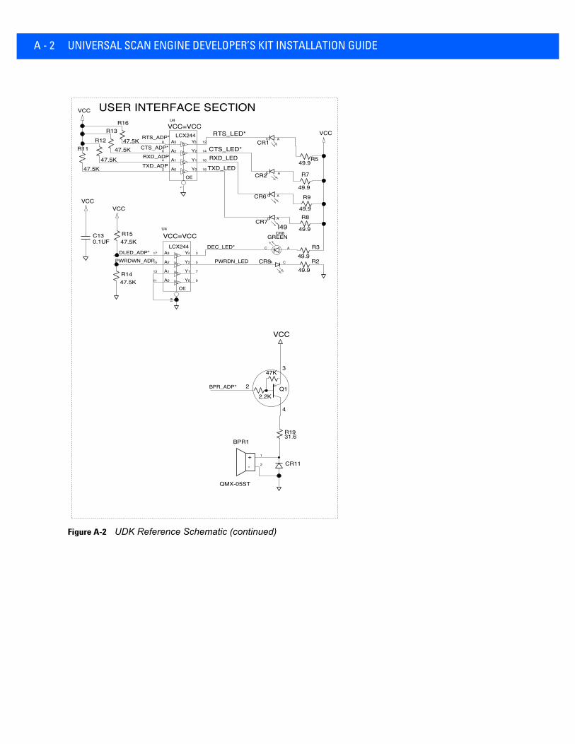
Figure A-2 UDK Reference Schematic (continued)
LCX244
OE
Y
Y
Y
Y
A
A
A
A
3
2
1
0
3
2
1
0
LCX244
OE
Y
Y
Y
Y
A
A
A
A
3
2
1
0
3
2
1
0
R16
47.5K
R13
47.5KR12
47.5K
VCCVCC
R1547.5K
C130.1UF
R1447.5K
R11
47.5K
R1931.6
47K
2.2K
Q1
CR11
BPR1
QMX-05ST
+-
VCC
VCC
49.9R5
CR1
CR2
49.9
R7
49.9
R9CR6
CR7
49.9
R8
49.9R3
49.9R2 CR9
VCC USER INTERFACE SECTION
CTS_LED*RXD_LED
TXD_LED
VCC=VCC
CTS_ADP*
1
2
3
4
2
3
5
7
9
19
17
15
13
11
U4
12
14
16
18
1
8
6
4
2
U4
CA
C A
CR8
C A
C A
C A
C A
VCC=VCC
I49GREEN
RTS_ADP*
TXD_ADP
PWRDWN_ADP
RTS_LED*
RXD_ADP
DEC_LED*
PWRDN_LED
DLED_ADP*
BPR_ADP*

REFERENCE SCHEMATIC A - 3
Figure A-3 UDK Reference Schematic (continued)
RZIF20_SMDJ4 - J4 - J4 - J4 - J4 - J4 - J4 - J4 - J4 - J4 - J4 - J4 -
-RZIF20SMD-MOLJ23
-
J23-
J23
-
J23-
J23
-
J23-
J23
-
J23-
J23
-
J23-
J23
-
J23-
J23
-
J23-
J23
-
J23-
J23
-
J23-
J23
-
J23-
J23
-
J23-
J23
-
J23-
J23
-
J23-
J23
-
J23-
J23
-
J23
10KR25
10KR24
RZIFP6-JAEJ8 - J8 - J8 - J8 - J8 - J8 - J8 - J8 - J8 - J8 - J8 -
0 R20
0 R21
SCAN ENGINE INTERFACE(SE X22X/824)
(PL4407)
CSE 600 DECODED
12 PIN DECODED
SCAN ENGINE INTERFACE
CONNECTORSENGINE/DECODER INTERFACE
HOST CONNECTOR
USB_OUT+USB_OUT-
HSSI0_RXFSHSSI0_RXCLKHSSI0_TXCLKTRIG*
BPR*
VCC_JUMP3
USB_VCC_IN
PWRDWN
VCC_JUMP2
DLED*
RXD
RTS*CTS*TXD
PWRDWN
TRIG*AIM*DLED*
RXDTXDRTS*CTS*
DLED*BPR*PWRDWN
TRIG*AIM*
TXDCTS*RXD
EXT_ILLUM_CNTL2SYS_CONFIG1
DNLD*
BPR*
DNLD*VCC_JUMP1
HSSI0_TXFS
RTS*
HSSI0_TXDATHSSI0_RXDAT
USB_VCC_REG
VCC_JUMP1
AIM*
SYS_CONFIG0
123456789101112
123456789101112131415161718192021222324252627282930
1234567891011
A - 4 UNIVERSAL SCAN ENGINE DEVELOPER’S KIT INSTALLATION GUIDE
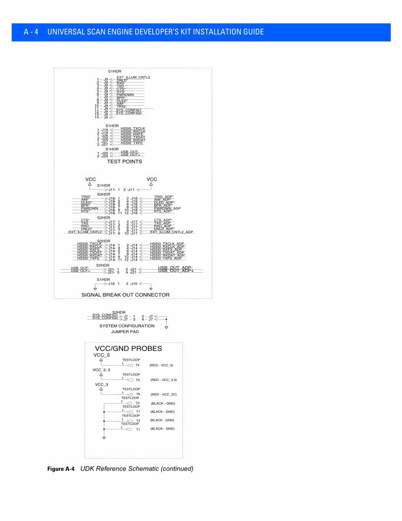
Figure A-4 UDK Reference Schematic (continued)
TESTLOOPT4
VCC_5
VCC_3_3
VCC_3
TESTLOOP
T5
TESTLOOPT6
TESTLOOPT2
TESTLOOPT7
TESTLOOPT3
TESTLOOP
T1
S1HDR
J9- J9- J9- J9- J9- J9- J9- J9- J9- J9- J9- J9- J9- J9-
S2HDRJ18- J18- J18- J18- J18- J18-
J18- J18- J18- J18- J18- J18-
J14-
J14-
J14-
J14-
J14- J14-
S2HDRJ14-
J14-
J14-
J14-
J14-
J14-
J11S1HDR
- J11
-
VCC VCC
S2HDRJ17- J17- J17- J17-
J17- J17- J17- J17- J17-
J17-
S2HDRJ7 - J7 -
J7- J7-
J10S1HDR
- J10
-
S2HDRJ21- J21-
J21- J21-
J20S1HDR
-J20
-
J19S1HDR
-J19
-J26
-J26
-J27
-J27
-
SYSTEM CONFIGURATION
VCC/GND PROBES
(RED - VCC_5)
(BLACK - GND)
(BLACK - GND)
(RED - VCC_3.3)
(RED - VCC_3V)
(BLACK - GND)
(BLACK - GND)
SIGNAL BREAK OUT CONNECTOR
TEST POINTS
JUMPER PAD
24
TXD_ADPDNLD_ADP*
SYS_CONFIG1TRIG*AIM*DLED*BPR*PWRDWNRTS*CTS*TXDRXDDNLD*
TXD
EXT_ILLUM_CNTL2_ADP
HSSI0_TXCLK
CTS_ADP*
USB_OUT_ADP-USB_OUT_ADP+
HSSI0_TXFS
USB_OUT-
RXD_ADP
HSSI0_TXDAT_ADP
RTS*
EXT_ILLUM_CNTL2
USB_OUT+
HSSI0_TXDATHSSI0_RXDAT
DNLD*RXD
HSSI0_TXCLK_ADP
BPR*DLED*PWRDWN
SYS_CONFIG1SYS_CONFIG0
AIM_ADP*
RTS_ADP*
HSSI0_RXCLK
AIM*TRIG*
HSSI0_RXFS
USB_OUT-USB_OUT+
HSSI0_TXFSHSSI0_RXDATHSSI0_TXDAT
TRIG_ADP*
BPR_ADP*
CTS*
HSSI0_RXFS
PWRDWN_ADP
HSSI0_RXCLK_ADP
DLED_ADP*
HSSI0_RXFS_ADPHSSI0_RXDAT_ADPHSSI0_TXFS_ADP
EXT_ILLUM_CNTL2
SYS_CONFIG0
HSSI0_TXCLKHSSI0_RXCLK
1
1
1
1
1
1
1
123456789
1011121314
1357911
2468
1012
2
1210
846
1
9753
11
1 2
1357
2468
109
13
1 2
13
24
12
121212
REFERENCE SCHEMATIC A - 5
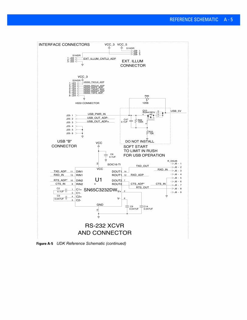
Figure A-5 UDK Reference Schematic (continued)
-J25
-J25
-J25
-J25
J24S2HDR
-J24
-J24
-J24
-J24
-J24
-J24
-J24
-
VCC_3
-J25
-J25
-J22S1HDR
-J22
-J22
U1
SN65C3232DW
VCC
0.047UFC5
0.047UFC9
0.047UFC14
0.1UFC6
0.1UFC2
J6R_DSUB
-J6
-
J6
-J6
-
J6
-J6
-
J6
-J6
-
J6
-
SI3441BDVQ10
R69100K
C470.1UF
10KR22
-J28S1HDR
-J28
-J28
VCC_3 VCC_5
0
R86
HSSI CONNECTOR
DO NOT INSTALLSOFT STARTTO LIMIT IN RUSHFOR USB OPERATION
RS-232 XCVRAND CONNECTOR
CONNECTORUSB "B"
INTERFACE CONNECTORS
EXT. ILLUMCONNECTOR
GND
VCC
C2-
DIN1RIN1
DIN2
C1+C1-C2+
RIN2
DOUT1ROUT1
DOUT2ROUT2
V+
V-
USB_5V
HSSI0_TXFS_ADP
HSSI0_RXCLK_ADP
EXT_ILLUM_CNTL2_ADP
RXD_IN
CTS_ADP*RTS_OUT
SOIC16-TI
RXD_ADP
CTS_IN
TXD_ADP
HSSI0_TXCLK_ADP
CTS_IN
TXD_OUT
RXD_IN
RTS_ADP*
USB_OUT_ADP+
HSSI0_TXDAT_ADPHSSI0_RXFS_ADP
1206
USB_PWR_INUSB_OUT_ADP-
HSSI0_RXDAT_ADP
1
456
12345678
23
123
1
10
11121314
1516
2345
6
78 9
123456789
12
56
34
123

A - 6 UNIVERSAL SCAN ENGINE DEVELOPER’S KIT INSTALLATION GUIDE
Figure A-6 UDK Reference Schematic (continued)
330
R4
VCC_5
J1
0.1UFC7
S4
C810UF +
60.4
R6
J12
-
J13S1HDR-
C160.1UF
J13
-
0.1UFC4
VCC_3_3VCC_5
J12
-
J12
-J12
-
J12
-J12
-
J12
-J12
-
J5S1HDR-
VCC
J5
-
J3S1HDR- J3
-
0.1UFC15
PL4407
SE-X22X/824
POWER JACK
CSE-600
5V POWER SUPPLY
+5V POWER
VCC TO ENGINES
VCC_JUMP3
BRD_PWR
USB_5V
5%25V
USB_5V
VCC_JUMP1
5%
VCC_JUMP2
USB_VCC_IN
16V
USB_VCC_REG
CR4A C
A
B
C
CN
C
NO
4
1 2
2
86
1357
1 2
1 2
20%
Aassembly drawing . . . . . . . . . . . . . . . . . . . . . . . . . . . 1-5
Bboard . . . . . . . . . . . . . . . . . . . . . . . . . . . . . . . . . . . . . 1-4
assembly drawing . . . . . . . . . . . . . . . . . . . . . . . . 1-5component descriptions . . . . . . . . . . . . . . . . . . . 2-1download button . . . . . . . . . . . . . . . . . . . . . . . . . 2-7external illumination interface . . . . . . . . . . . . . . . 2-7host communication . . . . . . . . . . . . . . . . . . . . . . 2-5mounting holes . . . . . . . . . . . . . . . . . . . . . . . . . . 2-9power configuration . . . . . . . . . . . . . . . . . . . . . . 2-2RS232 circuitry . . . . . . . . . . . . . . . . . . . . . . . . . . 2-8signal breakout . . . . . . . . . . . . . . . . . . . . . . . . . . 2-6USB power . . . . . . . . . . . . . . . . . . . . . . . . . . . . . 2-4user interface circuitry . . . . . . . . . . . . . . . . . . . . 2-8
Ccircuit board . . . . . . . . . . . . . . . . . . . . . . . . . . . . . . . 1-2contents of UDK . . . . . . . . . . . . . . . . . . . . . . . . . . . . 1-2conventions
notational . . . . . . . . . . . . . . . . . . . . . . . . . . . . . . . viii
Ddevelopment board . . . . . . . . . . . . . . . . . . . . . . . . . . 1-4
assembly drawing . . . . . . . . . . . . . . . . . . . . . . . . 1-5component descriptions . . . . . . . . . . . . . . . . . . . 2-1download button . . . . . . . . . . . . . . . . . . . . . . . . . 2-7external illumination interface . . . . . . . . . . . . . . . 2-7host communication . . . . . . . . . . . . . . . . . . . . . . 2-5mounting holes . . . . . . . . . . . . . . . . . . . . . . . . . . 2-9power configuration . . . . . . . . . . . . . . . . . . . . . . 2-2RS232 circuitry . . . . . . . . . . . . . . . . . . . . . . . . . . 2-8
signal breakout . . . . . . . . . . . . . . . . . . . . . . . . . . 2-6USB power . . . . . . . . . . . . . . . . . . . . . . . . . . . . . 2-4user interface circuitry . . . . . . . . . . . . . . . . . . . . . 2-8
download button . . . . . . . . . . . . . . . . . . . . . . . . . . . . 2-7
Eelectrical schematic . . . . . . . . . . . . . . . . . . . . . . . . . . 2-2external illumination interface . . . . . . . . . . . . . . . . . . 2-7
jumpers . . . . . . . . . . . . . . . . . . . . . . . . . . . . . . . . 2-7
Hhost communication
configuration . . . . . . . . . . . . . . . . . . . . . . . . . . . . 2-5jumpers . . . . . . . . . . . . . . . . . . . . . . . . . . . . . . . . 2-5
Iinformation, service . . . . . . . . . . . . . . . . . . . . . . . . . . . ix
Jjumper configurations
external illumination interface . . . . . . . . . . . . . . . 2-7host communication . . . . . . . . . . . . . . . . . . . . . . 2-5power . . . . . . . . . . . . . . . . . . . . . . . . . . . . . . . . . . 2-2signal breakout . . . . . . . . . . . . . . . . . . . . . . . . . . 2-6USB power . . . . . . . . . . . . . . . . . . . . . . . . . . . . . 2-4
Mmechanical parts . . . . . . . . . . . . . . . . . . . . . . . . . . . . 1-2mounting
board . . . . . . . . . . . . . . . . . . . . . . . . . . . . . . . . . . 1-2considerations for engines . . . . . . . . . . . . . . . . . 1-3holes . . . . . . . . . . . . . . . . . . . . . . . . . . . . . . . . . . 2-9
INDEX

Index - 2 UNIVERSAL SCAN ENGINE DEVELOPER’S KIT INSTALLATION GUIDE
SE1524 . . . . . . . . . . . . . . . . . . . . . . . . . . . . . . . . 1-3SE3300/PL3307 . . . . . . . . . . . . . . . . . . . . . . . . . 1-3SE4500/PL4507 . . . . . . . . . . . . . . . . . . . . . . . . . 1-3SE655 . . . . . . . . . . . . . . . . . . . . . . . . . . . . . . . . . 1-3SE6700/PL6707 . . . . . . . . . . . . . . . . . . . . . . . . . 1-3SE955 . . . . . . . . . . . . . . . . . . . . . . . . . . . . . . . . . 1-3SE965 . . . . . . . . . . . . . . . . . . . . . . . . . . . . . . . . . 1-3
Nnotational conventions . . . . . . . . . . . . . . . . . . . . . . . . . viii
Ppower configuration . . . . . . . . . . . . . . . . . . . . . . . . . . 2-2
jumpers . . . . . . . . . . . . . . . . . . . . . . . . . . . . . . . . 2-2power enable headers . . . . . . . . . . . . . . . . . . . . 2-3
Rreference schematic . . . . . . . . . . . . . . . . . . . . . . . . . A-1RS232 circuitry . . . . . . . . . . . . . . . . . . . . . . . . . . . . . 2-8
Sschematic . . . . . . . . . . . . . . . . . . . . . . . . . . . . . . . . . A-1
electrical . . . . . . . . . . . . . . . . . . . . . . . . . . . . . . . 2-2screws . . . . . . . . . . . . . . . . . . . . . . . . . . . . . . . . . . . . 1-2SE1524
mounting . . . . . . . . . . . . . . . . . . . . . . . . . . . . . . . 1-3SE3300/PL3307
mounting . . . . . . . . . . . . . . . . . . . . . . . . . . . . . . . 1-3SE4500/PL4507
mounting . . . . . . . . . . . . . . . . . . . . . . . . . . . . . . . 1-3SE655
mounting . . . . . . . . . . . . . . . . . . . . . . . . . . . . . . . 1-3SE6700/PL6707
mounting . . . . . . . . . . . . . . . . . . . . . . . . . . . . . . . 1-3SE955
mounting . . . . . . . . . . . . . . . . . . . . . . . . . . . . . . . 1-3SE965
mounting . . . . . . . . . . . . . . . . . . . . . . . . . . . . . . . 1-3service information . . . . . . . . . . . . . . . . . . . . . . . . . . . .ixsignal breakout . . . . . . . . . . . . . . . . . . . . . . . . . . . . . 2-6
jumpers . . . . . . . . . . . . . . . . . . . . . . . . . . . . . . . . 2-6Simple Serial Interface
guide . . . . . . . . . . . . . . . . . . . . . . . . . . . . . . . . . . 1-1overview . . . . . . . . . . . . . . . . . . . . . . . . . . . . . . . 1-3
SNAPI . . . . . . . . . . . . . . . . . . . . . . . . . . . . . . . . . . . . 1-4SSI
guide . . . . . . . . . . . . . . . . . . . . . . . . . . . . . . . . . . 1-1overview . . . . . . . . . . . . . . . . . . . . . . . . . . . . . . . 1-3
Symbol Native Application Programming Interface . . 1-4
UUSB
jumper configurations . . . . . . . . . . . . . . . . . . . . . . 2-4power selection . . . . . . . . . . . . . . . . . . . . . . . . . . 2-4
user interface circuitry . . . . . . . . . . . . . . . . . . . . . . . . 2-8

GLOSSARY
AAperture. The opening in an optical system defined by a lens or baffle that establishes the field of view.
API. An interface by means of which one software component communicates with or controls another. Usually used to refer to services provided by one software component to another, usually via software interrupts or function calls
Application Programming Interface. See API.
ASCII. American Standard Code for Information Interchange. A 7 bit-plus-parity code representing 128 letters, numerals, punctuation marks and control characters. It is a standard data transmission code in the U.S.
Autodiscrimination. The ability of an interface controller to determine the code type of a scanned bar code. After this determination is made, the information content is decoded.
BBar. The dark element in a printed bar code symbol.
Bar Code. A pattern of variable-width bars and spaces which represents numeric or alphanumeric data in machine-readable form. The general format of a bar code symbol consists of a leading margin, start character, data or message character, check character (if any), stop character, and trailing margin. Within this framework, each recognizable symbology uses its own unique format. See Symbology.
Bar Code Density. The number of characters represented per unit of measurement (e.g., characters per inch).
Bar Height. The dimension of a bar measured perpendicular to the bar width.
Bar Width. Thickness of a bar measured from the edge closest to the symbol start character to the trailing edge of the same bar.
BIOS. Basic Input Output System. A collection of ROM-based code with a standard API used to interface with standard PC hardware.

Glossary - 2 UNIVERSAL SCAN ENGINE DEVELOPER’S KIT INSTALLATION GUIDE
Bit. Binary digit. One bit is the basic unit of binary information. Generally, eight consecutive bits compose one byte of data. The pattern of 0 and 1 values within the byte determines its meaning.
Bits per Second (bps). Bits transmitted or received.
Boot or Boot-up. The process a computer goes through when it starts. During boot-up, the computer can run self-diagnostic tests and configure hardware and software.
BOOTP. A protocol for remote booting of diskless devices. Assigns an IP address to a machine and may specify a boot file. The client sends a bootp request as a broadcast to the bootp server port (67) and the bootp server responds using the bootp client port (68). The bootp server must have a table of all devices, associated MAC addresses and IP addresses.
bps. See Bits Per Second.
Byte. On an addressable boundary, eight adjacent binary digits (0 and 1) combined in a pattern to represent a specific character or numeric value. Bits are numbered from the right, 0 through 7, with bit 0 the low-order bit. One byte in memory is used to store one ASCII character.
CCDRH. Center for Devices and Radiological Health. A federal agency responsible for regulating laser product safety.
This agency specifies various laser operation classes based on power output during operation.
CDRH Class 1. This is the lowest power CDRH laser classification. This class is considered intrinsically safe, even if all laser output were directed into the eye's pupil. There are no special operating procedures for this class.
CDRH Class 2. No additional software mechanisms are needed to conform to this limit. Laser operation in this class poses no danger for unintentional direct human exposure.
Character. A pattern of bars and spaces which either directly represents data or indicates a control function, such as a number, letter, punctuation mark, or communications control contained in a message.
Character Set. Those characters available for encoding in a particular bar code symbology.
Check Digit. A digit used to verify a correct symbol decode. The scanner inserts the decoded data into an arithmetic formula and checks that the resulting number matches the encoded check digit. Check digits are required for UPC but are optional for other symbologies. Using check digits decreases the chance of substitution errors when a symbol is decoded.
Codabar. A discrete self-checking code with a character set consisting of digits 0 to 9 and six additional characters: ( - $ : / , +).
Code 128. A high density symbology which allows the controller to encode all 128 ASCII characters without adding extra symbol elements.
Code 3 of 9 (Code 39). A versatile and widely used alphanumeric bar code symbology with a set of 43 character types, including all uppercase letters, numerals from 0 to 9 and 7 special characters (- . / + % $ and space). The code name is derived from the fact that 3 of 9 elements representing a character are wide, while the remaining 6 are narrow.
Code 93. An industrial symbology compatible with Code 39 but offering a full character ASCII set and a higher coding density than Code 39.
Glossary - 3
Code Length. Number of data characters in a bar code between the start and stop characters, not including those characters.
Cold Boot. A cold boot restarts the mobile computer and erases all user stored records and entries.
COM port. Communication port; ports are identified by number, e.g., COM1, COM2.
Continuous Code. A bar code or symbol in which all spaces within the symbol are parts of characters. There are no intercharacter gaps in a continuous code. The absence of gaps allows for greater information density.
Cradle. A cradle is used for charging the terminal battery and for communicating with a host computer, and provides a storage place for the terminal when not in use.
DDead Zone. An area within a scanner's field of view, in which specular reflection may prevent a successful decode.
Decode. To recognize a bar code symbology (e.g., UPC/EAN) and then analyze the content of the specific bar code scanned.
Decode Algorithm. A decoding scheme that converts pulse widths into data representation of the letters or numbers encoded within a bar code symbol.
Decryption. Decryption is the decoding and unscrambling of received encrypted data. Also see, Encryption and Key.
Depth of Field. The range between minimum and maximum distances at which a scanner can read a symbol with a certain minimum element width.
Discrete 2 of 5. A binary bar code symbology representing each character by a group of five bars, two of which are wide. The location of wide bars in the group determines which character is encoded; spaces are insignificant. Only numeric characters (0 to 9) and START/STOP characters may be encoded.
Discrete Code. A bar code or symbol in which the spaces between characters (intercharacter gaps) are not part of the code.
DRAM. Dynamic random access memory.
EEAN. European Article Number. This European/International version of the UPC provides its own coding format and
symbology standards. Element dimensions are specified metrically. EAN is used primarily in retail.
Element. Generic term for a bar or space.
Encoded Area. Total linear dimension occupied by all characters of a code pattern, including start/stop characters and data.
ENQ (RS-232). ENQ software handshaking is also supported for the data sent to the host.
ESD. Electro-Static Discharge

Glossary - 4 UNIVERSAL SCAN ENGINE DEVELOPER’S KIT INSTALLATION GUIDE
FFlash Disk. An additional megabyte of non-volatile memory for storing application and configuration files.
Flash Memory. Flash memory is responsible for storing the system firmware and is non-volatile. If the system power is interrupted the data is not be lost.
FTP. See File Transfer Protocol.
HHard Reset. See Cold Boot.
Host Computer. A computer that serves other terminals in a network, providing such services as computation, database access, supervisory programs and network control.
Hz. Hertz; A unit of frequency equal to one cycle per second.
IIDE. Intelligent drive electronics. Refers to the solid-state hard drive type.
IEC. International Electrotechnical Commission. This international agency regulates laser safety by specifying various laser operation classes based on power output during operation.
IEC60825-1 Class 1. This is the lowest power IEC laser classification. Conformity is ensured through a software restriction of 120 seconds of laser operation within any 1000 second window and an automatic laser shutdown if the scanner's oscillating mirror fails.
IEEE Address. See MAC Address.
Input/Output Ports. I/O ports are primarily dedicated to passing information into or out of the terminal’s memory. Series 9000 mobile computers include Serial and USB ports.
Intercharacter Gap. The space between two adjacent bar code characters in a discrete code.
Interleaved 2 of 5. A binary bar code symbology representing character pairs in groups of five bars and five interleaved spaces. Interleaving provides for greater information density. The location of wide elements (bar/spaces) within each group determines which characters are encoded. This continuous code type uses no intercharacter spaces. Only numeric (0 to 9) and START/STOP characters may be encoded.
Interleaved Bar Code. A bar code in which characters are paired together, using bars to represent the first character and the intervening spaces to represent the second.
Interleaved 2 of 5. A binary bar code symbology representing character pairs in groups of five bars and five interleaved spaces. Interleaving provides for greater information density. The location of wide elements (bar/spaces) within each group determines which characters are encoded. This continuous code type uses no intercharacter spaces. Only numeric (0 to 9) and START/STOP characters may be encoded.

Glossary - 5
I/O Ports. interface The connection between two devices, defined by common physical characteristics, signal characteristics, and signal meanings. Types of interfaces include RS-232 and PCMCIA.
IOCTL. Input/Output Control.
IP Address. (Internet Protocol address) The address of a computer attached to an IP network. Every client and server station must have a unique IP address. A 32-bit address used by a computer on a IP network. Client workstations have either a permanent address or one that is dynamically assigned to them each session. IP addresses are written as four sets of numbers separated by periods; for example, 204.171.64.2.
IPX/SPX. Internet Package Exchange/Sequential Packet Exchange. A communications protocol for Novell. IPX is Novell’s Layer 3 protocol, similar to XNS and IP, and used in NetWare networks. SPX is Novell's version of the Xerox SPP protocol.
IS-95. Interim Standard 95. The EIA/TIA standard that governs the operation of CDMA cellular service. Versions include IS-95A and IS-95B. See CDMA.
KKey. A key is the specific code used by the algorithm to encrypt or decrypt the data. Also see, Encryption and
Decrypting.
LLASER. Light Amplification by Stimulated Emission of Radiation.The laser is an intense light source. Light from a laser
is all the same frequency, unlike the output of an incandescent bulb. Laser light is typically coherent and has a high energy density.
Laser Diode. A gallium-arsenide semiconductor type of laser connected to a power source to generate a laser beam. This laser type is a compact source of coherent light.
Laser Scanner. A type of bar code reader that uses a beam of laser light.
LCD. See Liquid Crystal Display.
LED Indicator. A semiconductor diode (LED - Light Emitting Diode) used as an indicator, often in digital displays. The semiconductor uses applied voltage to produce light of a certain frequency determined by the semiconductor's particular chemical composition.
Light Emitting Diode. See LED.
Liquid Crystal Display (LCD). A display that uses liquid crystal sealed between two glass plates. The crystals are excited by precise electrical charges, causing them to reflect light outside according to their bias. They use little electricity and react relatively quickly. They require external light to reflect their information to the user.
Glossary - 6 UNIVERSAL SCAN ENGINE DEVELOPER’S KIT INSTALLATION GUIDE
MMIL. 1 1 mil = 1 thousandth of an inch.
Misread (Misdecode). A condition which occurs when the data output of a reader or interface controller does not agree with the data encoded within a bar code symbol.
NNominal. The exact (or ideal) intended value for a specified parameter. Tolerances are specified as positive and
negative deviations from this value.
Nominal Size. Standard size for a bar code symbol. Most UPC/EAN codes are used over a range of magnifications (e.g., from 0.80 to 2.00 of nominal).
NVM. Non-Volatile Memory.
OODI. See Open Data-Link Interface.
Open Data-Link Interface (ODI). Novell’s driver specification for an interface between network hardware and higher-level protocols. It supports multiple protocols on a single NIC (Network Interface Controller). It is capable of understanding and translating any network information or request sent by any other ODI-compatible protocol into something a NetWare client can understand and process.
Open System Authentication. Open System authentication is a null authentication algorithm.
PPAN . Personal area network. Using Bluetooth wireless technology, PANs enable devices to communicate wirelessly.
Generally, a wireless PAN consists of a dynamic group of less than 255 devices that communicate within about a 33-foot range. Only devices within this limited area typically participate in the network.
Parameter. A variable that can have different values assigned to it.
PC Card. A plug-in expansion card for laptop computers and other devices, also called a PCMCIA card. PC Cards are 85.6mm long x 54 mm wide, and have a 68 pin connector. There are several different kinds:
• Type I; 3.3 mm high; use - RAM or Flash RAM• Type II; 5 mm high; use - modems, LAN adaptors• Type III; 10.5 high; use - Hard Disks
PCMCIA. Personal Computer Memory Card Interface Association. See PC Card.

Glossary - 7
Percent Decode. The average probability that a single scan of a bar code would result in a successful decode. In a well-designed bar code scanning system, that probability should approach near 100%.
PING. (Packet Internet Groper) An Internet utility used to determine whether a particular IP address is online. It is used to test and debug a network by sending out a packet and waiting for a response.
Presentation Mode. Typically used when the digital scanner sits on a countertop or is mounted on a wall, in this mode, the digital scanner operates in continuous (constant-on) mode, where it automatically decodes a bar code presented in its field of view.
Print Contrast Signal (PCS). Measurement of the contrast (brightness difference) between the bars and spaces of a symbol. A minimum PCS value is needed for a bar code symbol to be scannable. PCS = (RL - RD) / RL, where RL is the reflectance factor of the background and RD the reflectance factor of the dark bars.
Programming Mode. The state in which a scanner is configured for parameter values. See Scanning Mode.
QQuiet Zone. A clear space, containing no dark marks, which precedes the start character of a bar code symbol and
follows the stop character.
QWERTY. A standard keyboard commonly used on North American and some European PC keyboards. “QWERTY” refers to the arrangement of keys on the left side of the third row of keys.
RRAM. Random Access Memory. Data in RAM can be accessed in random order, and quickly written and read.
Reflectance. Amount of light returned from an illuminated surface.
Resolution. The narrowest element dimension which is distinguished by a particular reading device or printed with a particular device or method.
RF. Radio Frequency.
ROM. Read-Only Memory. Data stored in ROM cannot be changed or removed.
Router. A device that connects networks and supports the required protocols for packet filtering. Routers are typically used to extend the range of cabling and to organize the topology of a network into subnets. See Subnet.
RS-232. An Electronic Industries Association (EIA) standard that defines the connector, connector pins, and signals used to transfer data serially from one device to another.

Glossary - 8 UNIVERSAL SCAN ENGINE DEVELOPER’S KIT INSTALLATION GUIDE
SScan Area. Area intended to contain a symbol.
Scanner. An electronic device used to scan bar code symbols and produce a digitized pattern that corresponds to the bars and spaces of the symbol. Its three main components are: 1) Light source (laser or photoelectric cell) - illuminates a bar code,; 2) Photodetector - registers the difference in reflected light (more light reflected from spaces); 3) Signal conditioning circuit - transforms optical detector output into a digitized bar pattern.
Scanning Mode. The scanner is energized, programmed and ready to read a bar code.
Scanning Sequence. A method of programming or configuring parameters for a bar code reading system by scanning bar code menus.
SDK. Software Development Kit
Self-Checking Code. A symbology that uses a checking algorithm to detect encoding errors within the characters of a bar code symbol.
Shared Key. Shared Key authentication is an algorithm where both the AP and the MU share an authentication key.
SHIP. Symbol Host Interface Program.
SID. System Identification code. An identifier issued by the FCC for each market. It is also broadcast by the cellular carriers to allow cellular devices to distinguish between the home and roaming service.
Soft Reset. See Warm Boot.
Space. The lighter element of a bar code formed by the background between bars.
Specular Reflection. The mirror-like direct reflection of light from a surface, which can cause difficulty decoding a bar code.
Standard Trigger Mode. The digital scanner uses this mode when lifted off the counter or removed from the wall mount. In this mode, aim the digital scanner at a bar code and pull the trigger to decode.
Start/Stop Character. A pattern of bars and spaces that provides the scanner with start and stop reading instructions and scanning direction. The start and stop characters are normally to the left and right margins of a horizontal code.
STEP. Symbol Terminal Enabler Program.
Subnet. A subset of nodes on a network that are serviced by the same router. See Router.
Subnet Mask. A 32-bit number used to separate the network and host sections of an IP address. A custom subnet mask subdivides an IP network into smaller subsections. The mask is a binary pattern that is matched up with the IP address to turn part of the host ID address field into a field for subnets. Default is often 255.255.255.0.
Substrate. A foundation material on which a substance or image is placed.
SVTP. Symbol Virtual Terminal Program.
Symbol. A scannable unit that encodes data within the conventions of a certain symbology, usually including start/stop characters, quiet zones, data characters and check characters.

Glossary - 9
Symbol Aspect Ratio. The ratio of symbol height to symbol width.
Symbol Height. The distance between the outside edges of the quiet zones of the first row and the last row.
Symbol Length. Length of symbol measured from the beginning of the quiet zone (margin) adjacent to the start character to the end of the quiet zone (margin) adjacent to a stop character.
Symbology. The structural rules and conventions for representing data within a particular bar code type (e.g. UPC/EAN, Code 39, PDF417, etc.).
TTCP/IP. (Transmission Control Protocol/Internet Protocol) A communications protocol used to internetwork dissimilar
systems. This standard is the protocol of the Internet and has become the global standard for communications. TCP provides transport functions, which ensures that the total amount of bytes sent is received correctly at the other end. UDP is an alternate transport that does not guarantee delivery. It is widely used for real-time voice and video transmissions where erroneous packets are not retransmitted. IP provides the routing mechanism. TCP/IP is a routable protocol, which means that all messages contain not only the address of the destination station, but the address of a destination network. This allows TCP/IP messages to be sent to multiple networks within an organization or around the world, hence its use in the worldwide Internet. Every client and server in a TCP/IP network requires an IP address, which is either permanently assigned or dynamically assigned at startup.
Telnet. A terminal emulation protocol commonly used on the Internet and TCP/IP-based networks. It allows a user at a terminal or computer to log onto a remote device and run a program.
Terminal Emulation. A “terminal emulation” emulates a character-based mainframe session on a remote non-mainframe terminal, including all display features, commands and function keys. The VC5000 Series supports Terminal Emulations in 3270, 5250 and VT220.
Terminate and Stay Resident (TSR). A program under DOS that ends its foreground execution to remain resident in memory to service hardware/software interrupts, providing background operation. It remains in memory and may provide services on behalf of other DOS programs.
TFTP. (Trivial File Transfer Protocol) A version of the TCP/IP FTP (File Transfer Protocol) protocol that has no directory or password capability. It is the protocol used for upgrading firmware, downloading software and remote booting of diskless devices.
Tolerance. Allowable deviation from the nominal bar or space width.
Transmission Control Protocol/Internet Protocol. See TCP/IP.
Trivial File Transfer Protocol. See TFTP.
TSR. See Terminate and Stay Resident.
UUDP. User Datagram Protocol. A protocol within the IP protocol suite that is used in place of TCP when a reliable
delivery is not required. For example, UDP is used for real-time audio and video traffic where lost packets are simply

Glossary - 10 UNIVERSAL SCAN ENGINE DEVELOPER’S KIT INSTALLATION GUIDE
ignored, because there is no time to retransmit. If UDP is used and a reliable delivery is required, packet sequence checking and error notification must be written into the applications.
UPC. Universal Product Code. A relatively complex numeric symbology. Each character consists of two bars and two spaces, each of which is any of four widths. The standard symbology for retail food packages in the United States.
VVisible Laser Diode (VLD). A solid state device which produces visible laser light.
WWarm Boot. A warm boot restarts the mobile computer by closing all running programs. All data that is not saved to
flash memory is lost.

72E-59636-05 Revision A - May 2015
Zebra Technologies CorporationLincolnshire, IL U.S.A.http://www.zebra.com
Zebra and the stylized Zebra head are trademarks of ZIH Corp., registered in many jurisdictions worldwide. All other trademarks are the property of their respective owners.©2015 ZIH Corp and/or its affiliates. All rights reserved.