UNIVERSAL PooL FILtER SyStEm owNER’S...
28
UNIVERSAL POOL FILTER SYSTEM OWNER’S MANUAL MODELS 4510 AND 4511 Sand not included. USE ONLY No. 20 Silica Sand with a particle size of 0.45 mm – 0.55 mm IMPORTANT DO NOT RETURN PRODUCT TO STORE For technical assistance and missing parts, call Customer Service toll-free 1.888.382.5988 (press 135 at any time) Monday through Friday, 8 am to 5:00pm MST Saturday, 8:00am to 1:00pm MST IMPORTANT SAFETY RULES Read all instructions BEFORE assembling and using this product. KEEP THIS MANUAL. MODEL 4510 MODEL 4511
Transcript of UNIVERSAL PooL FILtER SyStEm owNER’S...
UNIVERSAL PooL FILtER SyStEmowNER’S mANUAL
MODELS 4510 AND 4511
Sand not included. USE ONLY No. 20 Silica Sand with a particle size of 0.45 mm – 0.55 mmImPoRtANt
Do Not REtURN PRoDUct to StoREFor technical assistance and missing parts, call Customer Service toll-free
1.888.382.5988(press 135 at any time)
Monday through Friday, 8 am to 5:00pm MSTSaturday, 8:00am to 1:00pm MST
ImPoRtANt SAFEty RULES
Read all instructions BEFORE assembling and using
this product. KEEP THIS MANUAL.
MODEL 4510
MODEL 4511

2SAVE THESE INSTRUCTIONS
SAVE THESE INSTRUCTIONS3
Your AquaQuik™ Universal Pool Filter System has been engineered and manufactured to our highest standard for dependability,
ease of operation and safety. With proper care, it will give you years of durable, trouble-free performance. Thank you for your purchase.
PRIoR to ASSEmbLINg AND USINg thIS PRoDUct, cAREFULLy READ AND ADhERE to ALL cAUtIoN AND ImPoRtANt
NotIcES LocAtED thRoUghoUt thIS mANUAL. FAILURE to comPLy wIth thESE INStRUctIoNS mAy DAmAgE to thE PRoDUct oR cAUSE
SERIoUS PERSoNAL INjURy oR DEAth.
In this manual, some of the following callouts may be used. Please pay special attention to these. CAUTION, IMPORTANT and STOP have the following meanings:
cAUtIoNUsed when injury or accidents may occur if the operating instructions, work instructions, work
procedures, etc. are either NOT strictly adhered to or not carried out all.
ImPoRtANtUsed when damage to the device may occur if the operating instructions, work instructions,
work procedures, etc. are either NOT strictly adhered to or not carried out all.
StoPCalls attention to special details or information.
ImPoRtANt Do Not REtURN PRoDUct to StoRE
For technical assistance and missing parts, call Customer Service toll-free
1.888.382.5988(press 135 at any time)
Monday through Friday, 8 am to 5:00pm MSTSaturday, 8:00am to 1:00pm MST
4SAVE THESE INSTRUCTIONS
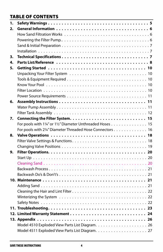
tAbLE oF coNtENtS1. Safety Warnings . . . . . . . . . . . . . . . . . . . . . . . . . . . . . . . . . . . . . 52. General Information . . . . . . . . . . . . . . . . . . . . . . . . . . . . . . . . . . 6
How Sand Filtration Works . . . . . . . . . . . . . . . . . . . . . . . . . . . . . . . . . 6Powering the Filter Pump. . . . . . . . . . . . . . . . . . . . . . . . . . . . . . . . . . . 6Sand & Initial Preparation . . . . . . . . . . . . . . . . . . . . . . . . . . . . . . . . . . 7Installation . . . . . . . . . . . . . . . . . . . . . . . . . . . . . . . . . . . . . . . . . . . 7
3. Technical Specifications . . . . . . . . . . . . . . . . . . . . . . . . . . . . . . . . 74. Parts List/Reference . . . . . . . . . . . . . . . . . . . . . . . . . . . . . . . . . . 85. Getting Started . . . . . . . . . . . . . . . . . . . . . . . . . . . . . . . . . . . . 10
Unpacking Your Filter System . . . . . . . . . . . . . . . . . . . . . . . . . . . . . . 10Tools & Equipment Required . . . . . . . . . . . . . . . . . . . . . . . . . . . . . . . 10Know Your Pool . . . . . . . . . . . . . . . . . . . . . . . . . . . . . . . . . . . . . . . 10Filter Location . . . . . . . . . . . . . . . . . . . . . . . . . . . . . . . . . . . . . . . . 10Power Source Requirements . . . . . . . . . . . . . . . . . . . . . . . . . . . . . . . 11
6. Assembly Instructions . . . . . . . . . . . . . . . . . . . . . . . . . . . . . . . . 11Water Pump Assembly . . . . . . . . . . . . . . . . . . . . . . . . . . . . . . . . . . . 11Filter Tank Assembly . . . . . . . . . . . . . . . . . . . . . . . . . . . . . . . . . . . . 12
7. Connecting the Filter System . . . . . . . . . . . . . . . . . . . . . . . . . . . . 15For pools with 1¼” or 1½” Diameter Unthreaded Hoses . . . . . . . . . . . . . . 15For pools with 2¼” Diameter Threaded Hose Connectors . . . . . . . . . . . . . 16
8. Valve Operations . . . . . . . . . . . . . . . . . . . . . . . . . . . . . . . . . . . 18Filter Valve Settings & Functions . . . . . . . . . . . . . . . . . . . . . . . . . . . . . 18Changing Valve Positions . . . . . . . . . . . . . . . . . . . . . . . . . . . . . . . . . 19
9. Filter Operations. . . . . . . . . . . . . . . . . . . . . . . . . . . . . . . . . . . . 20Start Up . . . . . . . . . . . . . . . . . . . . . . . . . . . . . . . . . . . . . . . . . . . . 20Cleaning Sand . . . . . . . . . . . . . . . . . . . . . . . . . . . . . . . . . . . . . . . . 20Backwash Process . . . . . . . . . . . . . . . . . . . . . . . . . . . . . . . . . . . . . . 21Backwash Do’s & Don’t’s . . . . . . . . . . . . . . . . . . . . . . . . . . . . . . . . . . 21
10. Maintenance . . . . . . . . . . . . . . . . . . . . . . . . . . . . . . . . . . . . . . 21Adding Sand . . . . . . . . . . . . . . . . . . . . . . . . . . . . . . . . . . . . . . . . . 21Cleaning the Hair and Lint Filter . . . . . . . . . . . . . . . . . . . . . . . . . . . . . 22Winterizing the System . . . . . . . . . . . . . . . . . . . . . . . . . . . . . . . . . . 22Safety Notes . . . . . . . . . . . . . . . . . . . . . . . . . . . . . . . . . . . . . . . . . 22
11. Troubleshooting . . . . . . . . . . . . . . . . . . . . . . . . . . . . . . . . . . . . 2312. Limited Warranty Statement . . . . . . . . . . . . . . . . . . . . . . . . . . . . 2413. Appendix . . . . . . . . . . . . . . . . . . . . . . . . . . . . . . . . . . . . . . . . 26
Model 4510 Exploded View Parts List Diagram . . . . . . . . . . . . . . . . . . . . 26Model 4511 Exploded View Parts List Diagram . . . . . . . . . . . . . . . . . . . . 27

SAVE THESE INSTRUCTIONS5
1. SAFEty wARNINgS
READ ALL wARNINgS bELow. FAILURE to Do So coULD RESULt IN SERIoUS PERSoNAL INjURy oR DEAth.
RISK OF SUCTION ENTRAPMENT HAZARD, WHICH, IF NOT AVOIDED CAN •RESULT IN SERIOUS INJURY OR DEATH. Do not block pump suction at the pump or in the pool as this can cause •severe injury or death.Electrical wiring MUST be installed by a trained professional and adhere •to local code and regulations.Avoid electric shock. DO NOT USE power extension cords. •Connect ONLY to a Ground-Fault Circuit Interrupter (GFCI) power outlet. •Consult a qualified, professional electrician for safe and proper installation of the required electrical outlet.Incorrectly installed equipment may fail, causing severe injuries or damage •to the pump-filter system.Never place or submerge the filter and/or pump in water. •Trapped air in the pump-filter system may cause the tank cover to be blown •off which can result in death, serious injury, or damage to the pump-filter system. Ensure all air is out of system before operating.NEVER change the position of the Multi-Port Valve while the system is •operating. ALWAYS unplug the system first. Install this product at least 10 feet away from the pool to prevent children •from using the system to access the pool.Never PLUG or UNPLUG this unit from an electrical source while standing •in water or with wet hands (or while wet??).NEVER service this unit with the electrical power cord connected.•Do not use any petroleum based lubricant. Petroleum based products will •destroy plastic parts.Do NOT operate the system while the pool is in use.•KEEP CHILDREN AWAY from all electrical equipment.•NEVER ALLOW CHILDREN TO OPERATE THIS EQUIPMENT.•
thESE SAFEty wARNINgS ARE Not INtENDED to INcoRPoRAtE ALL PoSSIbLE INStANcES FoR RISK AND/oR SEVERE INjURy.
6SAVE THESE INSTRUCTIONS
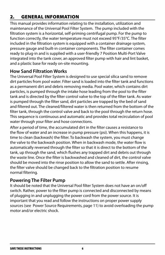
2. gENERAL INFoRmAtIoNThis manual provides information relating to the installation, utilization and maintenance of the Universal Pool Filter System. The pump included with the filtration system is a horizontal, self-priming centrifugal pump. For the pump to function correctly, the water temperature must not exceed 95°F/35°C. The filter included in the filtration system is equipped with a container drainage system, pressure gauge and built-in container components. The filter container comes ready to plug-in and is supplied with a user-friendly 7 Position Multi-Port Valve integrated into the tank cover, an approved filter pump with hair and lint basket, and a plastic base for ready on-site mounting.
How Sand Filtration WorksThe Universal Pool Filter System is designed to use special silica sand to remove dirt particles from pool water. Filter sand is loaded into the filter tank and functions as a permanent dirt and debris removing media. Pool water, which contains dirt particles, is pumped through the intake hose leading from the pool to the filter tank and is directed by the filter control valve to the top of the filter tank. As water is pumped through the filter sand, dirt particles are trapped by the bed of sand and filtered out. The cleaned/filtered water is then returned from the bottom of the filter tank, through the control valve and back to the pool through the return hose. This sequence is continuous and automatic and provides total recirculation of pool water through your filter and hose connections.After a period of time, the accumulated dirt in the filter causes a resistance to the flow of water and an increase in pump pressure (psi). When this happens, it is time to clean (backwash) the filter. To backwash the system, you must change the valve to the backwash position. When in backwash mode, the water flow is automatically reversed through the filter so that it is direct to the bottom of the tank, up through the sand, which flushes any trapped dirt and debris out through the waste line. Once the filter is backwashed and cleaned of dirt, the control valve should be moved into the rinse position to allow the sand to settle. After rinsing, the filter valve should be changed back to the filtration position to resume normal filtering.
Powering The Filter PumpIt should be noted that the Universal Pool filter System does not have an on/off switch. Rather, power to the filter pump is connected and disconnected by means of plugging in and unplugging the power cord from the power source. It is important that you read and follow the instructions on proper power supply sources (see Power Source Requirements, page 11) to avoid overloading the pump motor and/or electric shock.
SAVE THESE INSTRUCTIONS7
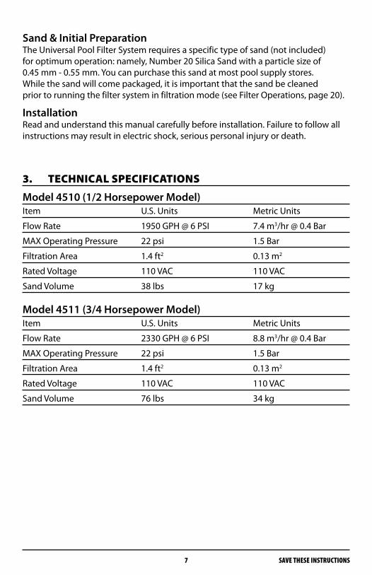
Sand & Initial PreparationThe Universal Pool Filter System requires a specific type of sand (not included) for optimum operation: namely, Number 20 Silica Sand with a particle size of 0.45 mm - 0.55 mm. You can purchase this sand at most pool supply stores. While the sand will come packaged, it is important that the sand be cleaned prior to running the filter system in filtration mode (see Filter Operations, page 20).
InstallationRead and understand this manual carefully before installation. Failure to follow all instructions may result in electric shock, serious personal injury or death.
3. tEchNIcAL SPEcIFIcAtIoNS
Model 4510 (1/2 Horsepower Model)Item U.S. Units Metric Units
Flow Rate 1950 GPH @ 6 PSI 7.4 m3/hr @ 0.4 Bar
MAX Operating Pressure 22 psi 1.5 Bar
Filtration Area 1.4 ft2 0.13 m2
Rated Voltage 110 VAC 110 VAC
Sand Volume 38 lbs 17 kg
Model 4511 (3/4 Horsepower Model)Item U.S. Units Metric Units
Flow Rate 2330 GPH @ 6 PSI 8.8 m3/hr @ 0.4 Bar
MAX Operating Pressure 22 psi 1.5 Bar
Filtration Area 1.4 ft2 0.13 m2
Rated Voltage 110 VAC 110 VAC
Sand Volume 76 lbs 34 kg
8SAVE THESE INSTRUCTIONS
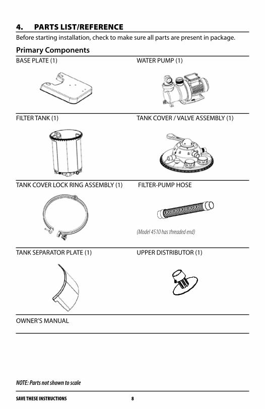
4. PARtS LISt/REFERENcEBefore starting installation, check to make sure all parts are present in package.
Primary ComponentsBASE PLATE (1) WATER PUMP (1)
FILTER TANK (1) TANK COVER / VALVE ASSEMBLY (1)
TANK COVER LOCK RING ASSEMBLY (1) FILTER-PUMP HOSE
(Model 4510 has threaded end)
TANK SEPARATOR PLATE (1) UPPER DISTRIBUTOR (1)
OWNER’S MANUAL
NOTE: Parts not shown to scale

SAVE THESE INSTRUCTIONS9
Parts Bag A 1 ¼”-1 ½” HOSE CONNECTOR (2) FLAT GASKET “A” (1)
O-RINGS (2) A: 2 ¼ “ Dia, B: 3” Dia HAIR & LINT STRAINER COVER (1)
Parts Bag BSHORT INTEX® CONNECTOR (1) LONG INTEX® CONNECTOR (1)
PUMP MOUNTING HARDWARE O-RING (1) C: 1¼” Dia
HOSE CLAMP (2) FLAT GASKET “B” (2)
NOTE: Parts not shown to scale
10SAVE THESE INSTRUCTIONS
5. gEttINg StARtED
Unpacking Your Filter SystemThis product requires assembly.Carefully remove the product and all parts. Make sure all items listed in the Parts List/Reference are included. Please note that some parts may be pre-assembled.Inspect everything carefully to make sure nothing is damaged.Do not discard packing material until you have satisfactorily operated the product.If any parts are missing or damaged, please call the number listed on the front page of this manual.NOTE: Some parts may be located within the filter tank. To access these parts you must remove the tank cover. Refer to Appendix A for a complete EXPLODED VIEW PARTS DIAGRAM
Tools & Equipment RequiredThe following items are not included with your new filter system, but will be required for proper installation and operation:
#2 Phillips Screwdriver•Rubber Mallet•No. 20 Silica Sand (Model 4510 requires 38 lbs of sand; Model 4511 •requires 76 lbs of sand.)A small container of silicone based lubricant•G.F.C.I. (Ground Fault Circuit Interrupter) – Must be installed by •a certified electricianOne 1½ inch backwash hose •
The above equipment list is based on the assumption that your above-ground pool is assembled, filled with water, and that your pool is equipped with the necessary filtration hoses needed to operate with a filter (cartridge or otherwise). If your pool is not assembled, please refer to the pool’s installation manual for details. If you do not have hoses for your pool’s intake and return, you will need to purchase the hoses from a pool supply store. This Universal Pool Filter System is designed to connect to pools with standard 1¼” or 1½” diameter hose connectors and has 2¼” hose adapters for INTEX® pools. If your pool has a hose connector with a different size and/or type, you may need to purchase an adapter at your local pool supply store or hardware retailer.
Know Your PoolBefore you begin installation, it is a good idea to know certain specifications of your pool:
How big is your pool? •How many gallons does it hold? •What size hose does it use? (i.e. 1¼” dia, 1½” dia or 2¼” dia) •What kind of hose connection does it use? ( i.e. threaded/unthreaded)•
SAVE THESE INSTRUCTIONS11
Filter LocationThe Universal Pool Filter System needs to be located on a 2’ x 3’ completely level, hard surface lower than the pool’s water level and at least 10 feet away from the pool. The hard surface may be made of concrete, gravel, patio pavers, etc.
Power Source RequirementsThe Universal Pool Filter System is equipped with a US standard electrical cord and plug which should only be connected to a power outlet protected by a qualified Ground-Fault Circuit Interrupter (GFCI) that has been installed by a professional electrician and adheres to local codes and regulations. To AVOID electric shock, serious personal injury or death, power cord extensions should NOT BE USED. DO NOT handle power cords or equipment with wet hands or while standing in water.
6. ASSEmbLy INStRUctIoNS
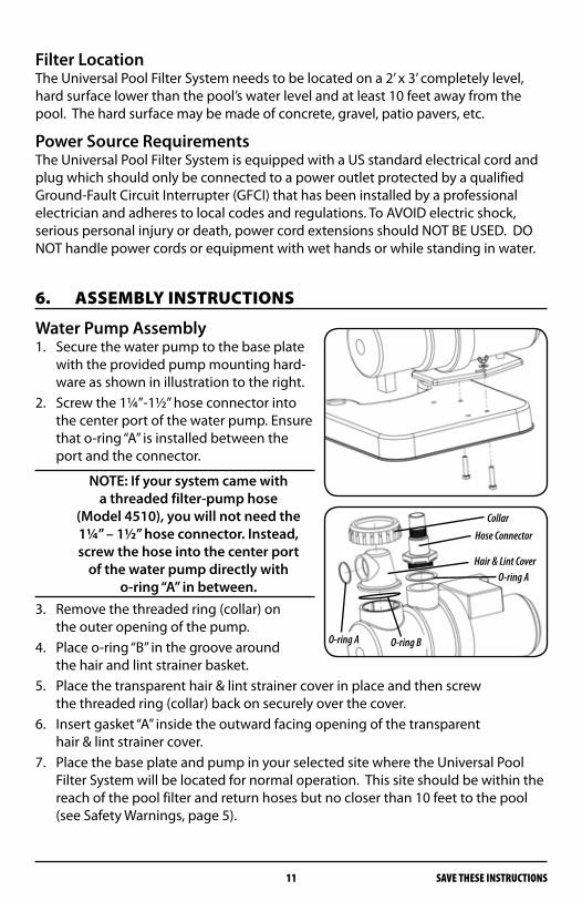
Water Pump Assembly1. Secure the water pump to the base plate
with the provided pump mounting hard-ware as shown in illustration to the right.
2. Screw the 1¼”-1½” hose connector into the center port of the water pump. Ensure that o-ring “A” is installed between the port and the connector.
NOTE: If your system came with a threaded filter-pump hose
(Model 4510), you will not need the 1¼” – 1½” hose connector. Instead, screw the hose into the center port
of the water pump directly with o-ring “A” in between.
3. Remove the threaded ring (collar) on the outer opening of the pump.
4. Place o-ring “B” in the groove around the hair and lint strainer basket.
5. Place the transparent hair & lint strainer cover in place and then screw the threaded ring (collar) back on securely over the cover.
6. Insert gasket “A” inside the outward facing opening of the transparent hair & lint strainer cover.
7. Place the base plate and pump in your selected site where the Universal Pool Filter System will be located for normal operation. This site should be within the reach of the pool filter and return hoses but no closer than 10 feet to the pool (see Safety Warnings, page 5).
Collar
Hair & Lint Cover
Hose Connector
O-ring A
O-ring A O-ring B

12SAVE THESE INSTRUCTIONS
Filter Tank Assembly1. Place the filter tank on the base plate as
shown. The feet on the bottom of the filter tank fit within the holes provided on the base plate.
2. Insert the tank separator plate inside the main tank in the guides provided. The plate divides the tank into two compartments, the Filtered Water Chamber and the Sand Filter Chamber.
3. Filling Sand Chamber with Sand
Note: The filter pump assembly should be in its permanent location before filling the chamber with sand. Otherwise, the unit will be heavy
and difficult to move around.a. Check to ensure that the
bottom strainer is correctly positioned.
b. Check to ensure that the tank separator plate is seated properly.
c. Fill the sand chamber half full with water.
ImPoRtANtTo prevent damage to the container and the bottom strainer, the container should be filled
with 8 – 12 INCHES of water before adding the filter sand.d. Pour Number 20 Silica Sand into the sand filter chamber being careful not to
allow any sand to enter the filtered water chamber. Model 4510 requires 38 lbs. of No. 20 Silica Sand. Model 4511 requires 76 lbs. of No. 20 Silica Sand.
Filtered Water Chamber Sand Chamber
SAVE THESE INSTRUCTIONS13
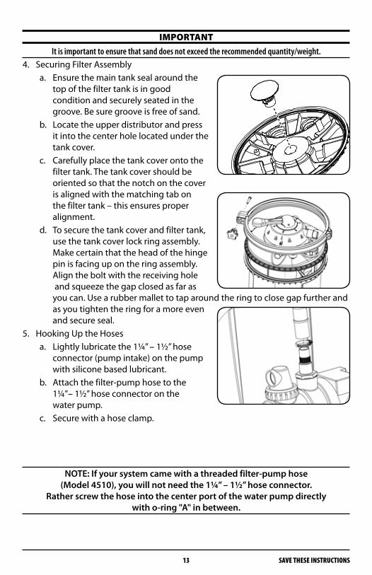
ImPoRtANtIt is important to ensure that sand does not exceed the recommended quantity/weight.
4. Securing Filter Assemblya. Ensure the main tank seal around the
top of the filter tank is in good condition and securely seated in the groove. Be sure groove is free of sand.
b. Locate the upper distributor and press it into the center hole located under the tank cover.
c. Carefully place the tank cover onto the filter tank. The tank cover should be oriented so that the notch on the cover is aligned with the matching tab on the filter tank – this ensures proper alignment.
d. To secure the tank cover and filter tank, use the tank cover lock ring assembly. Make certain that the head of the hinge pin is facing up on the ring assembly. Align the bolt with the receiving hole and squeeze the gap closed as far as you can. Use a rubber mallet to tap around the ring to close gap further and as you tighten the ring for a more even and secure seal.
5. Hooking Up the Hosesa. Lightly lubricate the 1¼” – 1½” hose
connector (pump intake) on the pump with silicone based lubricant.
b. Attach the filter-pump hose to the 1¼”– 1½” hose connector on the water pump.
c. Secure with a hose clamp.
NOTE: If your system came with a threaded filter-pump hose (Model 4510), you will not need the 1¼” – 1½” hose connector.
Rather screw the hose into the center port of the water pump directly with o-ring "A" in between.
14SAVE THESE INSTRUCTIONS
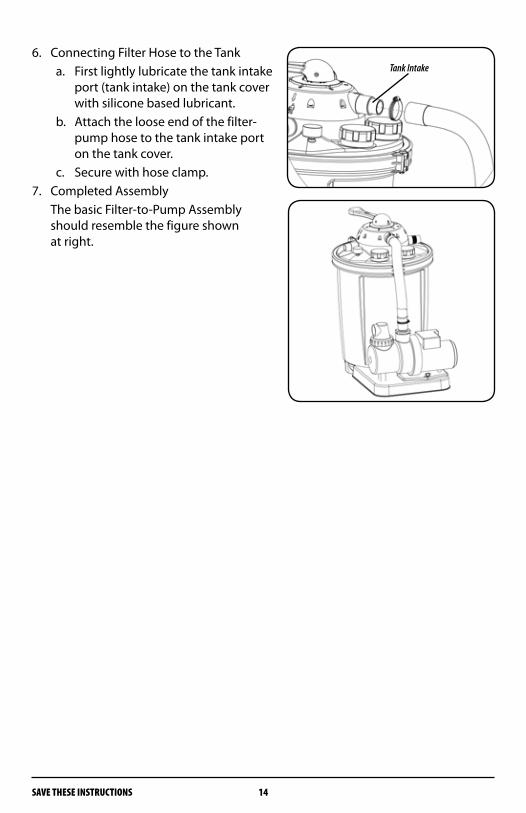
6. Connecting Filter Hose to the Tanka. First lightly lubricate the tank intake
port (tank intake) on the tank cover with silicone based lubricant.
b. Attach the loose end of the filter-pump hose to the tank intake port on the tank cover.
c. Secure with hose clamp.7. Completed Assembly The basic Filter-to-Pump Assembly
should resemble the figure shown at right.
Tank Intake
SAVE THESE INSTRUCTIONS15
7. coNNEctINg thE FILtER SyStEm The next section outlines installation instructions for connecting the Universal Pool Filter System to your pool. Since the hoses utilized for filtration and return lines differ for various types of above-ground pools, the pool-filter connection section is broken down by pool hose size and type. For pools with 1¼” or 1½” diameter unthreaded hoses, see ”A” below. For pools with 2¼” threaded hose connectors, see ”B” on following page.
StoPBefore you begin to connect hoses to the filter and pump, make certain that no water can flow
through the intake or return hoses connected to the pool. Some pools have shut off valves in their intake and return ports, others do not. If you do not have a shut off valve, block the ports
with a removable plug to prevent water from passing into and through the hoses.
A. For Pools with 1¼” or 1½ “Diameter Unthreaded HosesThese instructions assume that the pool is already assembled with hoses attached to the water intake and return ports on the pool.
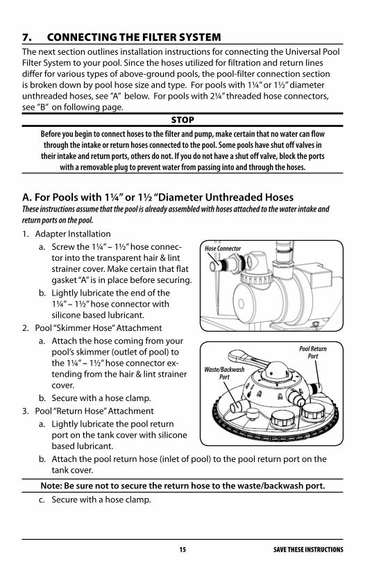
1. Adapter Installationa. Screw the 1¼” – 1½” hose connec-
tor into the transparent hair & lint strainer cover. Make certain that flat gasket “A” is in place before securing.
b. Lightly lubricate the end of the 1¼” – 1½” hose connector with silicone based lubricant.
2. Pool “Skimmer Hose” Attachmenta. Attach the hose coming from your
pool’s skimmer (outlet of pool) to the 1¼” – 1½” hose connector ex-tending from the hair & lint strainer cover.
b. Secure with a hose clamp.3. Pool “Return Hose” Attachment
a. Lightly lubricate the pool return port on the tank cover with silicone based lubricant.
b. Attach the pool return hose (inlet of pool) to the pool return port on the tank cover.
Note: Be sure not to secure the return hose to the waste/backwash port.c. Secure with a hose clamp.
Hose Connector
Waste/Backwash Port
Pool Return Port
16SAVE THESE INSTRUCTIONS
ImPoRtANtEnsure that all HOSE connections are tight and that the hoses are NOT kinked or bent at severe
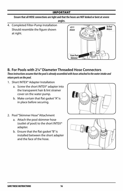
angles.4. Completed Filter-Pump Installation Should resemble the figure shown
at right.
B. For Pools with 2¼” Diameter Threaded Hose ConnectorsThese instructions assume that the pool is already assembled with hoses attached to the water intake and return ports on the pool.
1. Short INTEX® Adapter Installation a. Screw the short INTEX® adapter into
the transparent hair & lint strainer cover on the water pump.
b. Make certain that flat gasket “A” is in place before securing.
2. Pool “Skimmer Hose” Attachmenta. Attach the pool skimmer hose
(outlet of pool) to the short INTEX® adapter.
b. Ensure that the flat gasket “B” is installed between the short adapter and the face of the hose.
To Pool Return
From Pool Skimmer
4511 shown
SAVE THESE INSTRUCTIONS17
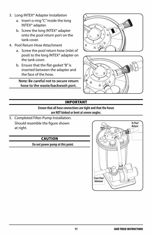
3. Long INTEX® Adapter Installationa. Insert o-ring “C” inside the long
INTEX® adapter.b. Screw the long INTEX® adapter
onto the pool return port on the tank cover.
4. Pool Return Hose Attachmenta. Screw the pool return hose (inlet of
pool) to the long INTEX® adapter on the tank cover.
b. Ensure that the flat gasket “B” is inserted between the adapter and the face of the hose.
Note: Be careful not to secure return hose to the waste/backwash port.
ImPoRtANtEnsure that all hose connections are tight and that the hoses
are NOT kinked or bent at severe angles.5. Completed Filter-Pump Installation. Should resemble the figure shown
at right.
cAUtIoNDo not power pump at this point.
To Pool Return
From Pool Skimmer

18SAVE THESE INSTRUCTIONS
8. VALVE oPERAtIoNSMake yourself familiar with your filter system’s valve settings and functions.
Filter Valve Settings & FunctionsSetting Complete Water Flow/Function Valve Diagram
Filtration Position 1
Function: Vacuum, regular pool filter action. This is the setting the filter will be set to most of the time. In this position, water is directed through the top of the filter where it compresses and flattens down the sand. Contaminants are trapped by the sand as water makes it way to the bottom strainer, out of the filter and back to the pool.
Rinse Position 2
Function: Use after backwashing to clean and resettle filter bed. This should always be done immediately after backwashing, new sand addition or filter start-up. In this position, water is directed to the top of the tank where it reseats the sand and flushes the valve while sending water out the waste line. This reduces the chance of contaminant blow back to the pool when the valve is moved back to the filtration position after backwashing.
Circulation Position 3
Function: circulate water after chemical treatment. This position is used during cer-tain pool cleanups and chemical treatments when you don’t want the water contaminat-ing the sand. In this position, water is only directed through the valve back to the pool and does not filter through the sand.
Backwash Position 4
Function: clean filter of captured debris. This is the position needed to clean the filter and sand. You’ll know it is time to backwash when the pressure gauge rises 5 to 10 psi above what it normally reads when the filter is clean. In this position, water is directed through the bottom strainer, reversing the flow through the tank. This causes the sand to separate and lift while releasing trapped debris out the waste line.
1
2
3
4
SAVE THESE INSTRUCTIONS19
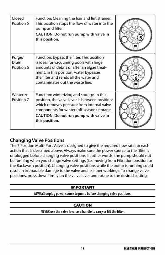
Closed Position 5
Function: Cleaning the hair and lint strainer. This position stops the flow of water into the pump and filter.CAUTION: Do not run pump with valve in this position.
Purge/Drain Position 6
Function: bypass the filter. This position is ideal for vacuuming pools with large amounts of debris or after an algae treat-ment. In this position, water bypasses the filter and sends all the water and contaminates out the waste line.
Winterize Position 7
Function: winterizing and storage. In this position, the valve lever is between positions which removes pressure from internal valve components for winter (off-season) storage.CAUTION: Do not run pump with valve in this position.
Changing Valve PositionsThe 7 Position Multi-Port Valve is designed to give the required flow rate for each action that is described above. Always make sure the power source to the filter is unplugged before changing valve positions. In other words, the pump should not be running when you change valve settings (i.e. moving from Filtration position to the Backwash position). Changing valve positions while the pump is running could result in irreparable damage to the valve and its inner workings. To change valve positions, press down firmly on the valve lever and rotate to the desired setting.
ImPoRtANtALWAYS unplug power source to pump before changing valve positions.
cAUtIoNNEVER use the valve lever as a handle to carry or lift the filter.
5
6
7
20SAVE THESE INSTRUCTIONS
9. FILtER oPERAtIoNS
Start UpOnce the filter system has been properly assembled, the sand chamber filled with sand and the hoses connected, you may begin with filtration. However, we recommend that you clean and prepare the new sand that is in the sand chamber first. Cleaning the sand prior to filtering your pool will remove most of the dust and tiny sand particles that may exist in the sand. If you move straight to filtering, these particles will end up in your pool. To clean the sand, please follow the instructions below.
Cleaning Sand1. Make certain the pump is not plugged in to a power supply.2. Start with the valve in the “5 - Closed” position.3. If you haven’t done so already, fill your pool with water. Ensure that the water
level is at least 1 – 2 inches above the top of the hose intake and return ports in the pool.
4. Release the shut off valve at the intake port in the pool. If you plugged the intake port, remove the plug to allow the water to flow into the intake hose.
5. With the filter-pump system installed in a location level lower than your pool’s water level – water will automatically flow into the pump-filter system.
6. Allow the filter tank to fill with water.7. Check for leaks and make any necessary adjustments.8. Follow the backwash process below.
Backwash Process 1. Disconnect the motor/pump from the power source.2. Attach backwash hose (not included) to backwash port.3. Place the multi-port valve in the “4 - Backwash” position.4. Reconnect to power source.5. Run filter in backwash mode until discharge water is clear.6. Disconnect the motor/pump from the power source.7. Place the multi-port valve in the “2 - Rinse” position.
cAUtIoNSee Power Source Requirements on page 11
8. Reconnect to power source.9. Allow filter to run for 60 seconds to remove any remaining residue from pump
and valve.10. Disconnect the motor/pump from the power source.11. Place the multi-port valve in the “1 - Filtration” position.12. Reconnect to power source. Your filtration system is running and ready for further operation.
SAVE THESE INSTRUCTIONS21
NOTE: When the filter pump is properly connected to the power supply, the pump will begin to push the water through the bed of sand and
out the backwash hose. In this process, water will be drained from your pool as it cleans the bed of sand within the tank. You may want to put a garden hose in the pool to add water in while the pump is pulling water
out so that the water level does not go below the intake return ports. While the sand is being cleaned, run your fingers through the water exiting the backwash hose. When you can no longer feel sandy grit
in the water, the sand cleaning process should be complete.
Backwash Do's and Dont'sBe aware and make note of the filter pressure when the sand is clean. Backwash when you see an increase of 5 – 10 psi on the pressure gauge.
• Backwashlongenoughtogetthejobdoneright.Letthesystembackwashuntil the water exiting the waste line is clear. Note that backwashing can remove 50 -300 gallons of water from your pool so pay attention. Also, be aware of local codes regarding pool water disposal as some communities outlaw drainage.
• Don’tbackwashexcessively.Sandfiltersoperatemoreefficientlyduringmid-cycle. Some level of debris in the sand bed actually helps filtration and makes the filter more effective. Too much backwashing will reduce efficiency.
• Don’tvacuumthepoolinbackwashmode.Youcanplugupthestraineratthe bottom of the filter which will result in inefficient operation. Plus you may have to remove all of the sand to get it unclogged.
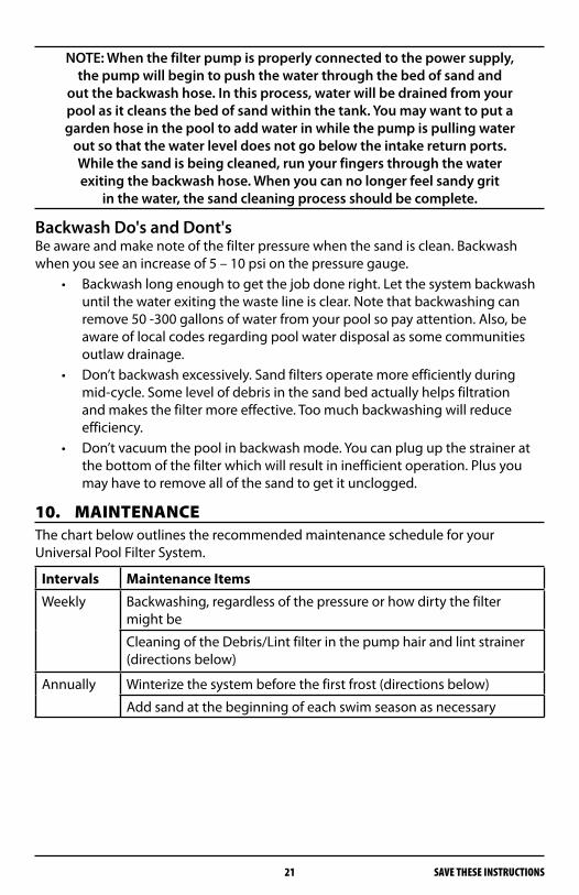
10. mAINtENANcEThe chart below outlines the recommended maintenance schedule for your Universal Pool Filter System.
Intervals Maintenance Items
Weekly Backwashing, regardless of the pressure or how dirty the filter might be
Cleaning of the Debris/Lint filter in the pump hair and lint strainer (directions below)
Annually Winterize the system before the first frost (directions below)
Add sand at the beginning of each swim season as necessary

22SAVE THESE INSTRUCTIONS
Adding New Sand• Protectbottomstrainerwhilereplacingoraddingsand.Fillthetankwitha
foot of water and cover the water chamber to avoid getting sand inside.• Startfilterinrinsemodefor1–3minutesafterinitialstartuporafter
adding new sand. By doing this you can avoid blowing small particles and impurities from the new sand into your pool. If some debris from the new sand does go into your pool, vacuum it up with the system in purge mode, otherwise you may keep sending it back to the pool.
cAUtIoNBefore loosening any threaded connections on the filtration system, be sure that the intake
and return hoses are closed or plugged to prevent water flow over the motor.
Cleaning the Hair and Lint Filter1. Unplug the pump from the power source.2. Close the shutoff valves or block the water flow at the pool inlet port.3. Place valve in the “5 - Closed“ position.4. Remove the hair & lint strainer cover on the pump by unscrewing the threaded
collar. Take out the strainer basket, clean it, and replace it. Replace the hair & lint strainer cover and tighten the threaded collar. DO NOT OVER TIGHTEN.
5. Open the shutoff valves or unblock the water flow at the pool inlet port.6. Place valve in the “1 - Filtration“ position.7. Reconnect to power source.
ImPoRtANtNEVER operate the pump without the hair and lint strainer basket in place – this can cause
damage to the motor and pump assembly.
Winterizing the System1. Unplug the pump from the power source.2. Close the shut off valves or block the flow of water at the pool inlet and return
ports. 3. Disconnect the filtration system from the pool, drain the tank and hoses.4. Place the handle on the central valve in position “7- Winterize" to relieve the ten-
sion on the spring and internal valve components.5. Store the filter system in a location protected from frost and freezing tempera-
tures.
Safety NotesIf there is any indication that safe operation is no longer possible, the device is to be disconnected from the power supply and secured against accidental use.This is the case when:
The device has visible damage•The device no longer appears functional•After long periods of storage in poor conditions•

SAVE THESE INSTRUCTIONS23
11. tRoUbLEShootINg
Problem Cause Solution
Pressure gauge has reading over 15 psi
Dirty filter bed Backwash the filter (position 4)
Pressure is too low
Hair and lint strainer basket is dirty
Clean the hair and lint strainer
Air in the pump Poor seal on the intake side of the pump.
Tighten hose clamps and connecting fittings.
Water flows into the drainpipe
Dirt around the seal of the Central Valve
Unscrew the central valve from tank cover and clean the seal
Leaking filter Seal Defective Check the seal, replace if needed
Pump does not run
Not plugged in Check the socket and power cord
G.F.C.I/ or main circuit breaker tripped
Switch on the breaker (if it is immediately tripped again, there is a defect in pump or controls)
Pump motor defective Replace the entire pump
Sand in Pool If the sand is newly replaced, the undersized grains are still present
Backwash several times until the backwash water is clear (position 4)
Sand in central valve (from backwash)
Purge into drainpipe for 30 seconds (position 6)
Separation wall in filter is improperly installed
Check the separation wall for proper positioning
Filter bottom strainer is damaged
Replace the filter bottom strainer
Air in system Loosen, but do not remove, the transparency cover on the filter tank to allow any trapped air to escape. Tighten the cover once all of the air has escaped.
StoPRepairs on the pump should only be performed by professionally
trained, qualified technicians.
24SAVE THESE INSTRUCTIONS
12. LImItED wARRANty StAtEmENtThe manufacturer warranties safe operation and reliability only under the following conditions: The filter system is installed and operated according to the assembly and operating instructions. Only original replacement parts are used. Consumable parts do NOT fall under the warrantyExpendable parts do NOT fall under the warranty. These include:
All O-rings (40x5 mm O-ring for tank cover, 105x5 mm O-ring for pump •cover, 58x6 mm O-ring for housing, 50x3 mm O-rings for hose connections, 6x2 mm O-rings for screws) Pressure Gauge• Hair & Lint Strainer Basket• Mechanical Seal, Complete• Filter-to-Pump Hose•
General TermsThis Limited Warranty applies to the enclosed product (the “Product”) distributed by Great American Duck Races, Inc., an Arizona corporation (doing business as Great American Marketing and Events) (“GAME”). GAME warrants that the Product will be free from defects in materials and workmanship under normal use for a period of one (1) year from the date of purchase. (Your dated sales or deliv-ery receipt, showing the date of your Product purchase, is your proof of the purchase date.) During the warranty period, GAME will repair or replace any defective parts at no charge. All defective parts that are replaced by GAME will be replaced, at GAME’s discretion, with ei-ther new parts or used parts that meet or exceed performance specifications for new parts. All parts removed from the Product under this warranty will become the property of GAME. Repair or replacement of any parts will not serve to extend the one (1) year warranty period. This Limited Warranty does not apply to expendable parts. This Limited Warranty does not extend to any product (a) from which the serial number has been removed or (b) that has been damaged or rendered defective (i) as a result of accident, misuse, abuse or other external causes; (ii) by operation outside the usage parameters stated in the manual that shipped with the Product; (iii) by the use of parts not manufactured or sold by GAME; or (iv) by modification or service by anyone other than GAME or an authorized GAME distributor.If a defect is identified within the warranty period, please contact GAME.EXCEPT FOR THE LIMITED WARRANTY SET FORTH ABOVE, GAME EXPRESSLY DISCLAIMS ALL OTHER WARRANTIES, WHETHER EXPRESS OR IMPLIED, ORAL OR STATUTORY (INCLUDING, WITHOUT LIMITATION, WARRANTIES OF MERCHANTABILITY AND FITNESS FOR A PARTICULAR PURPOSE). ANY IMPLIED WARRANTIES THAT MAY BE IMPOSED BY LAW ARE LIMITED TO THE TERMS OF THE ABOVE LIMITED WARRANTY.
SAVE THESE INSTRUCTIONS25
ImPoRtANt Do Not REtURN PRoDUct to StoRE
For technical assistance and missing parts, call Customer Service toll-free
1.888.382.5988(press 135 at any time)
Monday through Friday, 8 am to 5:00pm MSTSaturday, 8:00am to 1:00pm MST
Limitation of LiabilityEXCEPT FOR THE LIMITED WARRANTY DESCRIBED ABOVE, IN NO EVENT WILL GAME HAVE ANY LIABILITY OF ANY KIND WHATSOEVER (WHETHER UNDER CONTRACT, TORT, OR ANY OTHER THEORY OF LEGAL LIABILITY) TO ANY PERSON WITH RESPECT TO THE PRODUCT (INCLUDING, WITHOUT LIMITATION, (A) ANY USE OR MISUSE OF THE PROD-UCT, (B) ANY FAILURE OR MALFUNCTION OF THE PRODUCT, (C) ANY BODILY INJURY, DEATH, LOSS OF OR DAMAGE TO ANY PROPERTY, OR ANY OTHER DAMAGES RELATED TO OR RESULTING FROM THE PRODUCT OR ITS USE (INCLUDING, WITHOUT LIMITATION, ANY SPECIAL, INCIDENTIAL, CONSEQUENTIAL OR PUNITIVE DAMAGES, LOST PROFITS, LOSS OF USE), EVEN IF GAME OR GAME’S AUTHORIZED REPRESENTATIVES HAVE BEEN ADVISED OF THE POSSIBILITY OF ANY SUCH DAMAGES. SeverabilityAny provision of this Limited Warranty which is prohibited or unenforceable in any jurisdiction will, as to such jurisdiction, be ineffective to the extent of such prohibition or unenforceability without invalidating the remaining portions hereof or affecting the validity or enforceability of such provision in any other jurisdiction.Venue and Choice of LawThis Limited Warranty is applicable in all countries. This Limited Warranty will be governed by the laws of the State of Arizona (regardless of any conflict of laws rules), and any disputes arising from this Limited Warranty will be resolved in Phoenix, Arizona.Entire Agreement This Limited Warranty is understood to be the complete and exclusive agreement between GAME and the purchaser of the Product, superseding all prior agreements, oral or written, and all other communications between such parties relating to the Product. No employee or representative of GAME or any other party is authorized to make any warranty in addition to the limited warranty set forth above.
26SAVE THESE INSTRUCTIONS
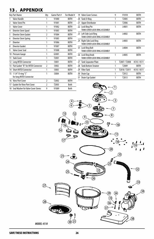
13 . APPENDIxKey Part Name Qty Game Part # For Model #1 Valve Handle 1 V1000 BOTH2 Valve Stem Pin 1 V1001 BOTH3 Valve Cover 1 V1002 BOTH4 Diverter Stem Spool 1 V1003 BOTH5 Diverter Stem Gasket 2 V1004 BOTH6 Diverter Stem Spring 1 V1005 BOTH7 Diverter 1 V1006 BOTH8 Diverter Gasket 1 V1007 BOTH9 Valve Cover Seal 1 V1008 BOTH10 Pressure Gauge 1 G5001 BOTH11 Tank Cover 1 T2001 BOTH12 Long INTEX Connector 1 I3001 BOTH13 Flat Gasket "B" for INTEX Connector 2 I3002 BOTH14 Short INTEX Connector 1 I3003 BOTH15 1 1/4" O-ring "C" 1 I3004 BOTH
for long INTEX Connector16 View Port Cover 2 T2002 BOTH17 Gasket for View Port Cover 2 T2003 Both18 Seal Washer for Valve Cover Stems 9 V1009 Both
19 Valve Cover Screws 9 V1010 BOTH20 Tank O-Ring 1 T2005 BOTH21 Upper Distributor 1 T2006 BOTH22 Lock Ring Pin 1 L4001 BOTH
TANK COVER LOCK RING ASSEMBLY23 Left Side Lock Ring 1 L4002 BOTH
TANK COVER LOCK RING ASSEMBLY24 Right Side Lock Ring 1 L4003 BOTH
TANK COVER LOCK RING ASSEMBLY25 Lock Ring Bolt 1 L4004 BOTH
TANK COVER LOCK RING ASSEMBLY26 Lock Ring Knob 1 L4005 BOTH
TANK COVER LOCK RING ASSEMBLY27 Tank Separator Plate 1 T2007 / T2008 4510 / 451128 Tank Bottom Strainer 1 T2009 BOTH29 Filter Tank 1 T2010 / T2011 4510 / 451130 Drain Cap 1 T2012 BOTH31 Drain Cap Gasket 1 T2013 BOTH
MODEL 4510

SAVE THESE INSTRUCTIONS27
32 Filter Pump Hose 1 P6001 / P6002 4510 / 451133 Hose Clamp 2 P6003 BOTH34 Pump Bolt Wing Nut 2 P6004 BOTH
PUMP MOUNTING HARDWARE35 Pump Bolt Flat Water 2 P6005 BOTH
PUMP MOUNTING HARDWARE36 Pump Bolt Lock Washer 2 P6006 BOTH
PUMP MOUNTING HARDWARE37 Pump Bolt 2 P6007 BOTH
PUMP MOUNTING HARDWARE38 Base Plate 1 B7001 BOTH39 Water Pump / Motor 1 P6010 / P6011 4510 / 451140 Transparent Hair & Lint Strainer Cover 1 P6012 BOTH41 1¼" - 1½" Hose Connector 2 P6013 BOTH42 O-RING "A" - 2 1/4 " 1 P6014 BOTH43 O-RING "B" - 3" 1 P6015 BOTH44 FLAT GASKET "A" 1 P6016 BOTH45 Strainer Collar 1 P6017 BOTH46 Strainer Basket 1 P6018 BOTH
MODEL 4511
Great American Merchandise & Events™16043 N. 82nd StreetScottsdale, AZ 85260-1800 U.S.A.
tel: 888.382.5988, 602.957.3825 fax: 602.957.7665
email: [email protected]/retailers
4510_11 R1 INSTR (012109)© 2008 GAME™ All rights reserved. Information subject to change.
ImPoRtANt Do Not REtURN PRoDUct to StoRE
For technical assistance and missing parts, call Customer Service toll-free
1.888.382.5988(press 135 at any time)
Monday through Friday, 8 am to 5:00pm MSTSaturday, 8:00am to 1:00pm MST
Look for other GAME products at your favorite store or visit our website, www.game-group.com/retailers.