
Universal Mobile Telecommunication Systems … SMG 21st meeting TDoc. 190/97 10-14 February 1997...
22
ETSI SMG 21st meeting TDoc. 190/97 10-14 February 1997 ETSI Standard Universal Mobile Telecommunication Systems (UMTS); System concepts and reference model for the UMTS (UMTS 21.01 V1.0.0) Note: This doc is as immediately at the end of SMG5#20, with some editorial checking to be done.
Transcript of Universal Mobile Telecommunication Systems … SMG 21st meeting TDoc. 190/97 10-14 February 1997...

ETSI SMG 21st meeting TDoc. 190/97 10-14 February 1997
ETSI Standard
Universal Mobile Telecommunication Systems (UMTS);System concepts and reference model for the UMTS
(UMTS 21.01 V1.0.0)
Note: This doc is as immediately at the end of SMG5#20, with some editorial checking to be done.

Error! Bookmark not defined.2Error! Style not defined.
Reference ES (0000031D.PDF)
Keywords <keyword[, keyword]>
ETSI Secretariat
Postal address F-06921 Sophia Antipolis Cedex - FRANCE
Office address 650 Route des Lucioles - Sophia Antipolis
Valbonne - FRANCE Tel.: +33 4 92 94 42 00 Fax: +33 4 93 65 47 16
Siret N° 348 623 562 00017 - NAF 742 C Association à but non lucratif enregistrée à la Sous-Préfecture de Grasse (06) N° 7803/88
X.400 c= fr; a=atlas; p=etsi; s=secretariat
Internet [email protected] http://www.etsi.fr
Copyright Notification
No part may be reproduced except as authorized by written permission. The copyright and the foregoing restriction extend to reproduction in all media.
© European Telecommunications Standards Institute 1997.
All rights reserved.

Error! Bookmark not defined.3Error! Style not defined.
CONTENTS
INTELLECTUAL PROPERTY RIGHTS 5
FOREWORD 5
1 SCOPE 6
2 NORMATIVE REFERENCES 6
3 DEFINITIONS, SYMBOLS AND ABBREVIATIONS 6
3.1 Definitions 6
3.2 Symbols 6
3.3 Abbreviations 7
4 UMTS SYSTEM CONCEPT FROM DIFFERENT VIEWPOINTS 7
4.1 Environmental viewpoint 8
4.2 UMTS Player Viewpoint 8 4.2.1 User 9 4.2.2 Subscriber 10 4.2.3 Value Added Service Provider 10 4.2.4 Service provider 10 4.2.5 Network operator 10 4.2.6 Content provider 10 4.2.7 Regulator 10
4.3 Services viewpoint 11
4.4 Mobility viewpoint 11
4.5 Security viewpoint 12
4.6 Management viewpoint 12
4.7 Evolution viewpoint 12 4.7.1 Evolution towards UMTS 12 4.7.2 Evolution of UMTS 13 4.7.3 Migration 13
4.8 System implementation viewpoint 13 4.8.1 Radio Access Network Viewpoint 13 4.8.2 Core network viewpoint 14 4.8.3 Satellite System Viewpoint 14
4.9 UMTS User equipment viewpoint 14

Error! Bookmark not defined.4Error! Style not defined.
5 UMTS PHASE 1 REFERENCE MODEL 14
5.1 Basic UMTS Phase 1 Reference Model 15
5.2 Basic UMTS Phase 1 Reference Model with multimode operation 17
5.3 UMTS Phase 1 Network Management Reference Model 17
5.4 UMTS Phase 1 Inter-network traffic reference model 19
5.5 UMTS Phase 1 Lawful Interception Reference Model 20
HISTORY 21
Error! Bookmark not defined.5Error! Style not defined.
Intellectual Property Rights This clause is always the first unnumbered clause.
The following fixed text elements for the IPR clause are identified. Choose either the "unidentified" or the "identified" case.
IPR unidentified ETSI has not been informed of the existence of any Intellectual Property Right (IPR) which could be, or could become essential to the present document. However, pursuant to the ETSI Interim IPR Policy, no investigation, including IPR searches, has been carried out. No guarantee can be given as to the existence of any IPRs which are, or may be, or may become, essential to the present document.
IPR identified The following fixed text elements for the IPR clause are identified. Choose either the "unidentified" or the "identified" case.
The attention of ETSI has been drawn to the Intellectual Property Rights (IPRs) listed below which are, or may be, or may become, essential to the present document. The IPR owner has undertaken to grant irrevocable licences on fair, reasonable and non-discriminatory terms and conditions to these IPRs pursuant to the ETSI Interim IPR Policy. Further details pertaining to these IPRs can be obtained directly from the IPR owner.
Notified IPRs
Company Country Application number(s) Patent number(s) NOTE:
Pursuant to the ETSI Interim IPR Policy, no investigation, including IPR searches, has been carried out by ETSI. No guarantee can be given as to the existence of other IPRs, which are, or may be, or may become, essential to the present document.
Foreword [To be provided by ETSI Secretariat]

Error! Bookmark not defined.6Error! Style not defined.
1 Scope This European Telecommunications Standards Institute Standard (ES) defines the system concept and specifies the reference models and associated terminology for the UMTS. In particular, this ES, which supports the requirements stated in this document, UMTS ETRs and regulatory documents forms the basis for the phase 1 reference model and reference points.
2 Normative references This ES incorporates by dated and undated reference, provisions from other publications. These normative references are cited at the appropriate places in the text and the publications are listed hereafter. For dated references, subsequent amendments to or revisions of any of these publications apply to this ES only when incorporated in it by amendment or revision. For undated references, the latest edition of the publication referred to applies.
[1] ETR 271 : “Special Mobile Group (SMG) Universal Mobile Telecommunications System (UMTS); Objectives and system overview (UMTS 01.01)”
[2] Technical input to ERC/ERO study on Universal Mobile Telecommunications System (UMTS) frequencies
[3] ETR 309: “Special Mobile Group (SMG); Vocabulary for the Universal Mobile Telecommunications System (UMTS) (UMTS 01.02)”
[4] ETR 312: “Special Mobile Group (SMG)“Special Mobile Group (SMG); Scenarios and considerations for the introduction of the Universal Mobile Telecommunications System (UMTS) (UMTS 01.04)”
[5] Draft DES/SMG - 0102201U “Special Mobile Group (SMG); Universal Mobile Telecommunications System (UMTS); Service Aspects and Service Principles (UMTS 22.01)”
[6] ETSI Global Multimedia Report
3 Definitions, symbols and abbreviations
3.1 Definitions For the purposes of this ES the following definitions apply
Player: an organisation which undertakes one or more roles.
Reference Point: a point seperating functional groups.
Role: an attribute of a player when considering it within relationships withone or more other players, which also play a role: it is a description of the actions and responsibilities of a player in the relationship.
3.2 Symbols For the purposes of this ETS, the following symbols apply.
Au Reference point between IWF1 and GSM/UMTS CN Bu Reference point between IWF3 and B-ISDN/UMTS CN Cu Reference point between USIM and Terminal

Error! Bookmark not defined.7Error! Style not defined.
Gbu Reference point between IWF1 and GSM Packet Data (CN1) Iu Reference point between RAN and interworking functions on the core network side Nu Reference point between IWF2 and N-ISDN (CN2) Pu Reference point between IWF4 and packet data network based core network Uu Reference point between AN and MT
3.3 Abbreviations For the purposes of this ETS, the following abbreviations apply.
AN Access Network CN Core Network GRAN Generic Radio Access Network IWF InterWorking Function MT Mobile Termination RAN Radio Access Network TE Terminal Equipment
4 UMTS system concept from different viewpoints The UMTS System Concept enables network operators to provide universal seamless mobile telecommunications coverage, in diverse multi-operator, multi-vendor, regulated environments in which converged fixed and mobile operation is possible. Multiple advanced and diverse services such as for example high bit rate and multimedia services including bandwidth-on-demand are supported with a flexible, open interface infrastructure which is capable of offering high capacity, with efficient use of resources. The UMTS system concept includes both terrestrial and satellite elements.
The UMTS System Concept supports the service requirement of the users in a consistent and personalised manner wherever he is located.
The UMTS System Concept provides for interworking with other telecommunications systems, including private networks such as office systems.
The UMTS System Concept allows the network infrastructure to support a wide diversity of terminal types and capabilities.
The UMTS system concept supports adaptive terminals able to access different radio access technologies, with the capability of being upgraded with the passage of time, adaptating the service capabilities to location, and support end to end negotiation to establish and maintain certain communication capability.
This ES defines the UMTS system concept from a number of different viewpoints. These viewpoints provide complementary perspectives of the UMTS system concept and are used to derive the UMTS reference models.
Viewpoints:
- Environmental
- Player
- Services
- Mobility
- Security
- Management
- Evolution
- System implementation
Error! Bookmark not defined.8Error! Style not defined.
- User equipment
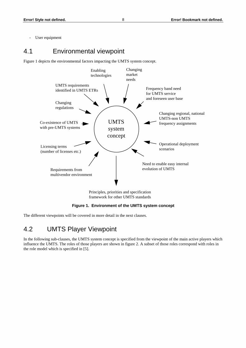
4.1 Environmental viewpoint Figure 1 depicts the environmental factors impacting the UMTS system concept.
UMTSsystemconcept
Requirements frommultivendor environment
Licensing terms(number of licenses etc.)
Co-existence of UMTSwith pre-UMTS systems
Changing regulations
UMTS requirementsidentified in UMTS ETRs
Enablingtechnologies
Changingmarketneeds
Frequency band needfor UMTS serviceand foreseen user base
Changing regional, nationalUMTS-non UMTSfrequency assignments
Operational deploymentscenarios
Need to enable easy internalevolution of UMTS
Principles, priorities and specificationframework for other UMTS standards
Figure 1. Environment of the UMTS system concept
The different viewpoints will be covered in more detail in the next clauses.
4.2 UMTS Player Viewpoint In the following sub-clauses, the UMTS system concept is specified from the viewpoint of the main active players which influence the UMTS. The roles of those players are shown in figure 2. A subset of those roles correspond with roles in the role model which is specified in [5].

Error! Bookmark not defined.9Error! Style not defined.
subscriber
user
serviceprovider
value addedservice provider
contentprovider
regulator
accessnetworkoperator
corenetworkoperator
Figure 2. UMTS System Concept Role Model
[Editor’s note : the possible seperation or merging of access network operator role and core network operator role is not yet finalised and is therefore for further study. This may be influenced by different operating scenarios, such as wide area or domestic cordless]
The following subclauses specify the UMTS system concept from the perspective of each role shown in figure 2. The relationship between the regulator role and the other roles is considered to be on a different plane than the other relationships shown in figure 2.
4.2.1 User
The user employs the diverse set of UMTS telecommunications capabilities to meet his changing needs.
The UMTS System Concept provides the user with universal access whenever or wherever required, for both private and professional uses.
This user may create his own personalised services and service profiles at will.
The UMTS System Concept recognises that the user may be an individual, legal entity, or non-bionic entity, (e.g. a remote unattended terminal or embedded radio in an automobile), or a user’s software agent; and that he user may be in some cases a group of related users, which may have special requirements.
Users, within the constraints of an individual subscription delegated to them, have choice of service provider, network operator, content provider etc, to best satisfy their current personal, technical and commercial needs, exercising this choice based on their requirements.
The UMTS system concept ensures that the user’s needs are catered for in a secure and reliable manner
The UMTS System Concept provides the user with the opportunities offered by developments in technology, while making some provision against premature obsolescence.
[Editor’s note - the following items deserve consideration for further input
user-owned number privacy fair and traceable charging reliable and robust accurate delivery to intended destination appropriate grade of service excellent value for money provision of services and customisation in a convenient manner, and appropriate to needs, e.g. support for multiple languages, sight or hearing impaired, etc.]

Error! Bookmark not defined.10Error! Style not defined.
4.2.2 Subscriber
The UMTS System Concept supports the establishment of contractual and commercial agreements between the subscriber and one or more service providers. The subscriber pays the charges for the telecommunications and other services provided to the users to which he has delegated his subscription.
4.2.3 Value Added Service Provider
The UMTS system concept supports the ability of custom-designed specialised functionality to provide a service of perceived value to a user or group of users. Subject to commercial arrangements with a Service Provider and Core Network Operator, a Value Added Service Provider may attach this specialised functionality to a UMTS Core Network. Definitions related to the Value Added Service Provider are given in [5].
4.2.4 Service provider
The UMTS System Concept supports a service provider role which provides the commercial interface between a subscriber (who may also be an end user), and a network operator and/or content provider, by which telecommunication network capabilities and/or access to information sources are made available to a user. This may include the bundling of a variety of individual offerings from a number of network operators or content providers. This role does not preclude any direct commercial arrangements between the end user and information networks or providers, e.g. Internet Service Providers, etc., nor does it imply a one-to-one relation between subscriber and service provider.
4.2.5 Network operator
The UMTS system concept enables access and core network operators to deploy and operate UMTS networks in a locality, country, group of countries, Region, or globally, usually under licence from the appropriate regulatory body, and normally satisfying designated coverage and service quality requirements.
There are two types of network operators:
- The access network operator provides wireless access and wide area coverage. The access network operator is entitled to use the frequencies. (In GSM this would correspond to a BSS operator)
- The core network operator provides the backbone network. The access signalling [e.g. Q.931] is terminated here.
4.2.6 Content provider
The UMTS system concept provides the means to allow users to access information content which is made available by the content provider. The access to the information content is provided in a secure way, thereby preventing unauthorised access where necessary. The UMTS system concept enables commercial exploitation of information content.
4.2.7 Regulator
The UMTS system concept allows regulatory authorities to create sufficient competion in the market place, subject to sufficient radio resources being made available. In addition, UMTS enables regulatory separation of roles where this separation is required. Also, where required for regulatory purposes, UMTS equipment enables authorised access to information being delivered or stored by UMTS. The UMTS system concept supports a multivendor and multi-operator commercial environment. The UMTS system concept includes provision for type approval of equipment.
The UMTS system concept recognises the possibility that number portability may be required by the regulator. Number portability is the capability of the user to change the service provider or network operator without changing the his/her number/address.

Error! Bookmark not defined.11Error! Style not defined.
4.3 Services viewpoint UMTS provides the necessary service capabilities to support a wide range of telecommunications services to the user, and in this respect is consistent with [6]. Details of the UMTS service principles and other aspects related to UMTS service capabilities are provided in [5].
4.4 Mobility viewpoint Terminal mobility
Terminal mobility in this context concerns the movement of a terminal associated with a user. The users want to be able to make and receive calls irrespective of their location. There are different levels terminal mobility.
1) Change of radio access port (antenna/cell/sector) within same access network
2) Change of access network without changing core network
3) Change of core network
Within each mobility level the changes may occur either during call/connections (handover) or between calls/connections (location update and roaming).
The UMTS system concept provides for users using both GSM/DCS/DECT and UMTS radio accesses. Depending on the support a core network platform can give handover between GSM/DCS/DECT and UMTS for relevant services are supported. The UMTS system concept also provides for a user to roam between different core network types (e.g. between GSM/UMTS and B-ISDN/UMTS). Handover is not mandatory in this case but may be supported.
User Mobility
The USIM will enable the user to change terminal.
Virtual Home Environment (VHE)
The Home Environment is the way a user normally interacts with his terminal to access services and information. The Virtual Home Environment ensures that the personalised user interactions are maintained for any terminal, anywhere.
Service Profile Portability
Service profile portability in this context is the capability for a user to have his service profile available on everywhere. It may be necessary for the user to have a restricted service profile, or alternatively different enhanced profiles the serving core and access network capabilities.
Change of Service Provider
Change of service provider means a change of subscription.
Inter-Regional Mobility
Inter-regional terminal roaming is be achieved:
- either if the different regions use the same technology; or
- by the use of multimode terminals where at least one of the modes is a UMTS mode; or
- by the use of adaptive terminals capable of supporting at least a UMTS mode; or
- by the use of a terminal capable of using the UMTS satellite component.
In the case of the adaptive terminal, the UMTS system concept provides the means to adapt the terminal to a UMTS mode of operation.
Inter-regional user roaming is achieved by the use of a USIM implemented as a removable module.

Error! Bookmark not defined.12Error! Style not defined.
4.5 Security viewpoint The UMTS system concept contains security-related measures to safeguard the interests of each of the roles shown in the UMTS system concept role model of figure 2.
The management system ensures that access to, and manipulation of management information is available only to authorised entities, both internally and to external systems. Where management information communications are involved e.g., between the terminal, access network and the core network, it shall possible to ensure secure communications.
4.6 Management viewpoint The UMTS system concept supports three hierarchical levels of management. - Service Management layer, Network Management layer and Element Management layer, as shown in figure 6.
The Service Management layer is responsible for two main types of service management activities:
- service development and maintenance activities such as service creation, service provisioning, and service quality monitoring;
- customer interfacing activities such as sales and ordering, customer problem handling, and service invoicing.
The Network Management layer is responsible for the control and monitoring of the network:
- fault and alarm management activities such as fault collection, fault correlation, alarm creation and presentation, notification to service management layer and possibly notification to other core network management systems;
- performance management activities such as performance data collection, analysis, presentation and transfer to service management layer and possibly also to other core network management systems;
- configuration management activities such as installation, system tuning, and system optimisation;
- accounting management support such as charging.
The Element Management layer is responsible for managing the network elements on an individual basis:
- fault monitoring activities such as fault detection, logging, correlation, and notification to network management layer;
- performance management activities such as performance data collection, analysis, presentation and transfer to network management layer;
- configuration management support.
- accounting management support such as transfer of usage data.
The Access Network management system support limited access for the customer (e.g. a core network). It is also interoperable with other access and core network operators’ management systems. Within the Access Network the management part has multivendor capabilities at the network management and service management layers.
4.7 Evolution viewpoint
4.7.1 Evolution towards UMTS
The UMTS system concept provides mechanisms to support an evolution towards UMTS, based on existing and emerging mobile and fixed platforms. UMTS system concept supports the evolutionary introduction of UMTS by enabling the use of existing/evolving network infrastructure or services for the implementation of UMTS.

Error! Bookmark not defined.13Error! Style not defined.
4.7.2 Evolution of UMTS
The UMTS system concept allows for improvements to be made to UMTS with the passage of time. Within UMTS, backwards compatibility is maintained when UMTS components are enhanced and users are able to keep their UMTS terminals. Established UMTS services are maintained, as UMTS is enhanced.
4.7.3 Migration
Migration is defined as the movement of users and services to UMTS. The UMTS system concept supports the enhancement of services while retaining existing services if the operator chooses. The UMTS system concept allows operators to maintain existing customers as migration occurs. Where pre-UMTS systems such as GSM/DCS, DECT and S-PCN remain in operation after the establishment of UMTS, the UMTS system concept supports the migration of users to UMTS in response to increasing user requirements. Pricing also influences the migration of users to UMTS.
4.8 System implementation viewpoint The UMTS system concept supports the different needs of a different operators, which may have different strategies, customer demands, timescales and cost respectively. The UMTS system concept provides for system implementations based on a modular structure which allows for a multi-vendor supply of equipment. This modular approach enables the evolution of the modular structure and the individual modules. The UMTS system concept supports implementations which are capable of providing narrowband, wide-band and multi-media services (up to 2Mbps). The UMTS system concept provides for high capacity with high spectrum efficiency. In addition, the UMTS system concept allows for implemetations of UMTS which support the inegration of fixed, mobile and private services and networks. It also provides for multi-mode operation with a single user equipment between UMTS and GSM/DCS/DECT and/or HIPERLAN by using the same evolved core network with handover between them. This enables operators to differentiate between services and geographical areas. The multi-mode operation may be within the same frequency band and/or between frequency bands.
4.8.1 Radio Access Network Viewpoint
The UMTS system concept includes a radio access network (RAN), separate from the UMTS core network.
The UMTS radio access network provides local and wide area mobile access to a number of core networks (CN), including core networks of both mobile and fixed origin. The UMTS radio access network supports the variety of services that can be expected to be provided through these core networks, as well as UMTS specific services and services specific to mobile networks.
The term Generic Radio Access Network (GRAN) is used to denote that it is an access network, that uses radio technology for the physical access and efficiently supports a wide range of services through a number of core networks. These services are not fully defined, and are not standardised, in order to allow service provider specific sets of services.
The GRAN conceptually includes InterWorking Functions (IWFs) to efficiently adapt to a number of core networks and offer the services thereof. In that sense, the GRAN is Generic (within the limits of the UMTS service capabilities). The IWF may be null in some cases. A corresponding IWF is also present in the terminal, providing adaptation between the RAN and CN functions.
The UMTS radio interface is included in the UMTS GRAN. Access networks other than the UMTS GRAN, such as GSM BSS and DECT, may be operated in parallell and attached to the same core network infrastructure. These pre-UMTS access networks are not part of the UMTS GRAN, they may be a complement. As such, pre-UMTS access networks connected to a UMTS core network are also supported by the UMTS system concept.
The UMTS Mobile Termination (MT) is part of the terminal and part of the RAN. The Radio Access Network is a part of the GRAN.
Figure 4 illustrates these concepts.

Error! Bookmark not defined.14Error! Style not defined.
4.8.2 Core network viewpoint
UMTS is conceptually split into generic radio access network and core network. The core network will provide to the UMTS radio access network the necessary capabilities to support:
1) connectivity between UMTS radio access networks;
2) access to applications;
3) network features (eg. Mobility functions) and services.
The UMTS system concept includes different core network implementations based on evolutionary pre-UMTS standards, such as GSM, N-ISDN, B-ISDN, PDN and S-PCN. These core networks are called respectively GSM/UMTS Core Network (CN), N-ISDN/UMTS CN, B-ISDN/UMTS CN, PDN/UMTS CN and S-PCN/UMTS CN. The core networks are interconnected to the GRAN through an open interface which is based the core networks specific interfaces/protocols (e.g. A, Gb, Q.931 or Q.2931). Core network protocols implemented in the terminal include call control, mobility management and service management.
4.8.3 Satellite System Viewpoint
The UMTS satellite component provides global or wide-area regional radio access, network features (e.g. mobility) and service capabilities. Therefore the UMTS satellite component shall include functionality corresponding to a combined RAN and CN. It also contains satellite-specific capabilities, such as satellite constellation management. S-PCNs may be a basis for evolution towards UMTS.
4.9 UMTS User equipment viewpoint The UMTS user equipment supports functions specific to management of the radio interface and adapting information flows as necessary. It also provides a man machine interface to the user.
The UMTS system concept enables the user to attach external equipment to his UMTS terminal, thereby allowing applications resident on the external equipment to access the service capabilities of UMTS subject to the ability of the UMTS terminal to deliver those service capabilities.
The UMTS system concept supports the ability to modify adaptive terminals and adaptive USIMs by delivering software. This ability enables users to access new service capabilities and enables the adaptive terminal to interwork with different radio interfaces.
User equipment (UMTS terminal) consists of a physical mobile equipment ME and a detachable module USIM. Both ME and USIM, together or separately, have the capability to support a plurality of applications owned or managed by the UMTS network, a UMTS player or a third party. Such applications are exemplified by UIM as access condition to UMTS network, access procedures to various services and networks, various source coding functions, operator defined applications, user specific applications, and management of entities resident on USIM or ME.
In order to enable a large variety of USIM/ME capabilities, user identification and access condition to USIM are separated from access to USIM applications which may require variable levels of protection, depending on the owner and type of application.
All access conditions to service (except emergency service) or features shall be on USIM or attached to the presence of appropriate USIM within ME which is only providing the technical service capabilities.
5 UMTS Phase 1 reference model The UMTS reference model consists of several complementary reference models presented in the following clauses.
The existence of a reference point does not necessarily imply that a standard interface shall exist.
Equipment may contain more than one functional group.
Error! Bookmark not defined.15Error! Style not defined.
In the case of satellite, the satellite specific access and core network functions may differ from implementation to implementation.
A reference point may have multiple interface specifications.
5.1 Basic UMTS Phase 1 Reference Model
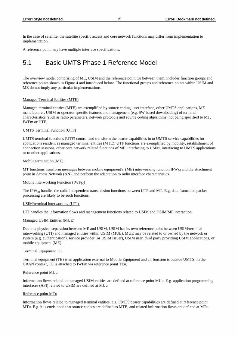
The overview model comprising of ME, USIM and the reference point Cu between them, includes function groups and reference points shown in Figure 4 and introduced below. The functional groups and reference points within USIM and ME do not imply any particular implementations.
Managed Terminal Entities (MTE)
Managed terminal entities (MTE) are exemplified by source coding, user interface, other UMTS applications, ME manufacturer, USIM or operator specific features and management (e.g. SW based downloading) of terminal characteristics (such as radio parameters, network protocols and source coding algorithms) not being specified to MT, IWFm or UTF.
UMTS Terminal Function (UTF)
UMTS terminal functions (UTF) control and transform the bearer capabilities in to UMTS service capabilities for applications resident as managed terminal entities (MTE). UTF functions are exemplified by mobility, establishment of connection sessions, other core network related functions of ME, interfacing to USIM, interfacing to UMTS applications or to other applications.
Mobile termination (MT)
MT functions transform messages between mobile equipment’s (ME) interworking function IFW M and the attachment point in Access Network (AN), and perform the adaptation to radio interface characteristics.
Mobile Interworking Function (IWF M)
The IFW M handles the radio independent transmission functions between UTF and MT. E.g. data frame and packet processing are likely to be such functions.
USIM/terminal interworking (UTI)
UTI handles the information flows and management functions related to USIM and USIM/ME interaction.
Managed USIM Entities (MUE)
Due to a physical separation between ME and USIM, USIM has its own reference point between USIM/terminal interworking (UTI) and managed entities within USIM (MUE). MUE may be related to or owned by the network or system (e.g. authentication), service provider (or USIM issuer), USIM user, third party providing USIM applications, or mobile equipment (ME).
Terminal Equipment TE
Terminal equipment (TE) is an application external to Mobile Equipment and all function is outside UMTS. In the GRAN context, TE is attached to IWFm via reference point TEu.
Reference point MUu
Information flows related to managed USIM entities are defined at reference point MUu. E.g. application programming interfaces (API) related to USIM are defined at MUu.
Reference point MTu
Information flows related to managed terminal entities, e.g. UMTS bearer capabilities are defined at reference point MTu. E.g. it is envisioned that source codecs are defined as MTE, and related information flows are defined at MTu.

Error! Bookmark not defined.16Error! Style not defined.
Reference point TEu
Information flows between GRAN and TE are defined at reference point TEu..
UTF IWF MT AN
IWF1
IWF2
IWF3
IWF4
GSM/UMTS CN
N-ISDN/UMTS CN
B-ISDN/UMTS CN
PDN/UMTS CN
UTI
Cu Du EuUu Iu
Gbu
Au
Nu
Bu
Pu
RANGRAN
IWFs S-PCN/UMTS CN
Su
Mobile Equipment (ME)
USIM
TEuTE
External Application
MTE
MTu
m
MUE
MUu
Figure 4. Basic UMTS Reference Model part 1.
Au
Nu
Bu
Pu
Su
VASESPE
X/UMTSCN
VAuSPu Ju
Ou Ku
VASESPE
Figure 4. Basic UMTS Reference Model part 2.
The abbreviations used in figure 4 part 2 are the following:
SPE Service Provider Entity. A given user is normally associated with a particular Service Provider Function. This SPF is considered to be the Home SPF for that user. The Home SPF contains permanent subscriber data for the given User. If a User is being served by an SPF which is not the Home SPF, for example due to roaming to another geographical area, then the serving SPF is considered to be the Temporary SPF for that user. The Temporary SPF contains temporary data relating to the visiting User.
VASE Value Added Service Provider Entity. VASFs provide a wide range of functions of perceived value to the User, this includes for example, managed access to information content.

Error! Bookmark not defined.17Error! Style not defined.
X/UMTS CN Any of the UMTS CNs shown in figure 4 part 1.
5.2 Basic UMTS Phase 1 Reference Model with multimode operation
MT AN
IWF1
IWF2
IWF3
IWF4
GSM/UMTS CN
N-ISDN/UMTS CN
B-ISDN/UMTS CN
PDN/UMTS CN
USIM
Cu EuUu Iu
Gbu
Au
Nu
Bu
Pu
GSM BSS
DECTFP
Um
A/Gb
N/A
N
IWFs S-PCN/UMTS CN
Su
S-PCN AN
Us-pcn
DU
HIPERLANAccess Point
HIWFH.1 H.2
Bu
Pu
Mobile Equipment (ME)
Figure 5. Basic UMTS Reference Model with multimode operation.
Figure 5 shows reference points for multimode UMTS terminal operation. Multimode operation of the terminal may be achieved by using multiple Mts in the terminal or by using an integrated multimode MT. Other modes are also possible, such as HIPERLAN.
The evolved core network (e.g. GSM/UMTS CN, N-ISDN/UMTS CN, etc.) offers compatibility with present version of these CNs (i.e. GSM CN, N-ISDN CN, etc.). However, this compatibility does not limit in any sense the UMTS GRAN capabilities.
5.3 UMTS Phase 1 Network Management Reference Model The reference model depicted in figure 6 depicts reference points valid in the access network (AN) management system, including service management. Core networks (CN) may use a layered management structure. However, interworking with other management systems, not based on a layered structure, are within the capabilities of the AN management system.

Error! Bookmark not defined.18Error! Style not defined.
AN ServiceManagement
Layer
ANNetworkElement
AN ElementManagement
Layer
AN NetworkManagement
Layer
MCu
MBu
MAu
CoreNetwork
ManagementSystem
MDu
MEu
Service ProviderManagement
System
User/Subscriber
MFu
MGu
AccessNetwork
ManagementSystem
Figure 6 Management Reference Model
The information flow at reference point MCu supports the service development and maintenance activities.
The information flow at reference point MDu supports the customer interfacing activities.
The information flows at reference points MBu , Mcu and MEu support network management layer activities.
The information flow at reference points Mau and MBu support element management layer activities. The element management layer provides the mapping from a proprietary representation of the network element to a standardised network view to support the management of a network.
The information flow at reference point MFu supports the service management activities (e.g. subscriber data and accounting information exchange).
The information flow at reference point MGu supports the subscriber and subscriber profile management related activities as well as the billing activities.
Reference Point MAu: Proprietary
Reference Points MBu, MCu, MDu , MEu, Mfu and MGu: Open
The reference points depict protocol-independent information flows. The interface protocol which allows access and core network management systems to communicate are core-network dependent.

Error! Bookmark not defined.19Error! Style not defined.
5.4 UMTS Phase 1 Inter-network traffic reference model
VASESPE
AN
ECN
IWFnX/UMTS
CN IuAu
Nu
Bu
Pu
Su
Yu
MuIGW
IGu
Lu
VAuSPu Ju
Ou Ku
VASESPE
NOTE: in most cases, a functional group may have relationships with multiple instances of another functional group.
Figure 7. UMTS Inter-network Traffic Reference Model.
The abbreviations used in figure 7 are the following:
SPF Service Provider Functions. A given user is normally associated with a particular Service Provider Function. This SPF is considered to be the Home SPF for that user. The Home SPF contains permanent subscriber data for the given User. If a User is being served by an SPF which is not the Home SPF, for example due to roaming to another geographical area, then the serving SPF is considered to be the Temporary SPF for that user. The Temporary SPF contains temporary data relating to the visiting User.
VASF Value Added Service Provider Functions. VASFs provide a wide range of functions of perceived value to the User, this includes for example, managed access to information content.
IWFn Any of the Interworking Functions, IWF1, IWF2, IWF 3, IW4 or IWFs shown in figure 4.
IGW Interrogating Gateway. IGW is the gateway which interrogates the location information (e.g. roaming number) of the called User and causes the call to be routed to the serving CN.
ECN External CN. Any of the UMTS CNs shown in figure 4 or a non-UMTS CN. Transit networks may be present between ECN and X/UMTS CN, however such transit networks are not shown. Where an ECN is not a UMTS CN, X/UMTS CN contains interworking functionality appropriate for interworking with the ECN

Error! Bookmark not defined.20Error! Style not defined.
5.5 UMTS Phase 1 Lawful Interception Reference Model
Service ProviderRelevantAuthority
CoreNetwork
GRAN
Serving UMTS network
X
Z
Figure 9 UMTS Phase 1 Lawful Interception Reference Model
Figure 9 depicts Lawful Interception Reference Points or Reference Points X and Z. Through reference point Z, the relevant authority can inform the service providerof which users are to be intercepted and can get information by telecommunications means from the databases of the service provider in order to be able to acquire the location (serving UMTS network) of the user when needed. Reference point X enables the authority to intercept the calls in the serving UMTS network.

Error! Bookmark not defined.21Error! Style not defined.
History
Document history
May 1996 Initiation of document within SMG5
30-May-1996 SMG5 No 17 - Restructured. Aligned with ETSI standards. New text on evolution.
28-June-1996 Changes from Kista meeting
Substantial material added to section 3
27-September-1996
SMG5 No 18 - Sections 3 and 4 as well as the scopeof the ETS and title of Section 5 modified. Version 0.0.5.
12 September 1996
SMG5 No 18 - Core network viewpoint added to paragraph 4.8.2 based on drafting activity of Mr Kriaras and Mr Soderbacka on TD 241. Version 0.0.6.
26 November 1996
Ad Hoc SMG5, Les Ulis - Further changes to sections 3, 4 and 5
12 December 1996
SMG5 No 19 - ,New section 4 taken largely from previous section 3.1. General re working of various subclauses
13 January 1996 SMG5 No 20 - ,New ES style, delete section 6 and annex 1, revise text to make consitent with figures, standard IPR clause added, terminal reference points updated.

Error! Bookmark not defined.22Error! Style not defined.