Universal II Series - SPX FLOW€¦ · · 2018-04-13Plan your next scan and download the Free SPX...
112
INSTRUCTION MANUAL Universal II Series ROTARY POSITIVE DISPLACEMENT PUMP FORM NO.: 95-03015 REVISION: 03/2017 READ AND UNDERSTAND THIS MANUAL PRIOR TO OPERATING OR SERVICING THIS PRODUCT.
-
Upload
duongtuong -
Category
Documents
-
view
214 -
download
1
Transcript of Universal II Series - SPX FLOW€¦ · · 2018-04-13Plan your next scan and download the Free SPX...

INSTRUCTION MANUAL
Universal II SeriesROTARY POSITIVE DISPLACEMENT PUMP
FORM NO.: 95-03015 REVISION: 03/2017 READ AND UNDERSTAND THIS MANUAL PRIOR TO OPERATING OR SERVICING THIS PRODUCT.

ADDING A POWERFUL NEW TOOL TO YOUR MAINTENANCE PROGRAM
SPX FLOW has recently launched its SPX Connect App allowing users the ability to access
product support information 24/7 using a smart device with internet access.
A quick scan of the product’s QR code will provide you with immediate access to:
• Product Descriptions and General Operating Specifi cations
• Maintenance Manuals and Documentation
• Maintenance Videos and Product Animations
• Distributor Look Up Feature
• Submit Quote Requests
SPX FLOW is committed to providing you with innovative products and technologies to help keep your
process fl owing. Plan your next scan and download the Free SPX Connect App today.
To learn more about SPX Connect, contact SPX FLOW at 800.252.5200 or wcb@spxfl ow.com.

Information contained in this manual is subject to change without notice and does not represent a commitment on the part of SPX FLOW, Inc.. No part of this manual may be reproduced or transmitted in any form or by any means, electronic or mechanical, including photocopying and recording, for any purpose, without the express written per-mission of SPX FLOW, Inc..
Copyright © 2017 SPX Corporation. All Rights Reserved.
Gore-Tex is a registered trademark of W.L. Gore & Associates, Inc. Kalrez is a registered trademark of DuPont Dow Elastomers.
Chemraz is a registered trademark of Greene, Tweed & Co
Revision Date: 03/2017
Publication: 95-03015
SPX FLOW, Inc.611 Sugar Creek Road
Delavan, WI 53115 USA
Tel: (800) 252-5200 or (262) 728-1900Fax: (800) 252-5012 or (262) 728-4904
E-mail: [email protected] site: www.spxflow.com

Table of Contents Waukesha Cherry-Burrell Brand Universal II Pump
Warranty ................................................................................................................... 6Shipping Damage or Loss ........................................................................................................6Warranty Claim ........................................................................................................................6
Safety ........................................................................................................................ 7Replacement Labels ................................................................................................ 8
Application Instructions ............................................................................................................8
Care of Component Materials ................................................................................. 9Stainless Steel Corrosion .........................................................................................................9Alloy 88 ....................................................................................................................................9Elastomer Seal Replacement Following Passivation ...............................................................9
Introduction ............................................................................................................ 10Pump Receiving .....................................................................................................................10Pump Characteristics .............................................................................................................10Equipment Serial Number ......................................................................................................10Pump Shaft Location ..............................................................................................................10Operating Parameters ............................................................................................................11Factory Remanufacturing Program ........................................................................................12
Installation .............................................................................................................. 13Install Pump and Drive Unit ....................................................................................................13Install Connections and Piping ...............................................................................................14Install Check Valves ...............................................................................................................15Install Isolation Valves ............................................................................................................15Install Relief Valves ................................................................................................................16Inlet Side Strainers and Traps ................................................................................................17Install Pressure Gauges .........................................................................................................17Seal Flush Connections .........................................................................................................17CIP (Clean-In-Place) Features ...............................................................................................19Check Coupling Alignment .....................................................................................................20Check Angular Alignment .......................................................................................................20Check Parallel Alignment .......................................................................................................20Check Belt and Chain Drive Alignment ..................................................................................21Check Pump Rotation ............................................................................................................21
Operation ................................................................................................................ 22Pre-Startup Checklist .............................................................................................................22Startup Procedure ..................................................................................................................22Shutdown Procedure ..............................................................................................................22
Maintenance ........................................................................................................... 23Important Safety Information ..................................................................................................23Lubrication ..............................................................................................................................23Maintenance Inspections .......................................................................................................24Annual Maintenance ..............................................................................................................27Cleaning .................................................................................................................................27Fluid Head Disassembly ........................................................................................................28Gear Case Disassembly ........................................................................................................31Shaft Assembly ......................................................................................................................33Gear Case Assembly .............................................................................................................36Fluid Head Assembly .............................................................................................................43Jacketed Cover ......................................................................................................................48
Troubleshooting .................................................................................................... 51
Page 4 95-03015 03/2017

Waukesha Cherry-Burrell Brand Universal II Pump Table of Contents
Long Term Storage ................................................................................................55Before Storage ...................................................................................................................... 55Storage .................................................................................................................................. 55After Storage ......................................................................................................................... 55
Parts List .................................................................................................................56006, 014, 015, 018-UII Pump Parts ....................................................................................... 56006, 014, 015, 018-UII Common Parts .................................................................................. 58030, 034, 040-UII Common Parts .......................................................................................... 64045, 060, 064, 130, 134-UII Pump Parts ............................................................................... 68045, 060, 064, 130, 134-UII Common Parts .......................................................................... 70180, 184, 220, 224-UII Pump Parts ....................................................................................... 74180, 184, 220, 224-UII Common Parts .................................................................................. 76210, 213, 214, 320, 323, 324, 370-UII Pump Parts ............................................................... 80210, 213, 214, 320, 323, 324, 370-UII Common Parts .......................................................... 82210, 213, 214, 320, 323, 324, 370--UII Common Parts ......................................................... 83Universal II Standard Seals ................................................................................................... 88Universal II Specialty Seals ................................................................................................... 90Shaft & Bearing Assemblies .................................................................................................. 96Grease Seals, Bearing Retainers, and Bearing Isolator Kits ................................................. 97Universal II PD Pump Vented Covers .................................................................................... 98Tru-Fit™ Universal II PD Pump ........................................................................................... 100Special Tools ....................................................................................................................... 101
Pump Dimensions ................................................................................................102ATEX Supplement to Universal II Operation Manuals ......................................107Universal II Maintenance Summary Reference Sheet .......................................108Universal II Maintenance Summary Reference Sheet -
Copy for optional removal ..................................................................109
03/2017 95-03015 Page 5

Warranty Waukesha Cherry-Burrell Brand Universal II Pump
Page 6 95-03015 03/2017
Warranty
LIMITED WARRANTY: Unless otherwise negotiated at the time of sale, SPX FLOW US, LLC (SPX FLOW) goods, auxiliaries and parts thereof are warranted to the original purchaser against defective workmanship and material for a period of twelve (12) months from date of installation or eighteen (18) months from date of shipment from factory, whichever expires first. If the goods or services do not conform to the warranty stated above, then as Buyer's sole remedy, SPX FLOW shall, at SPX FLOW's option, either repair or replace the defective goods or re-perform defective services. Third party goods furnished by SPX FLOW will be repaired or replaced as Buyer's sole remedy, but only to the extent provided in and honored by the original manufacturer's warranty. Unless otherwise agreed to in writing, SPX FLOW shall not be liable for breach of warranty or otherwise in any manner whatsoever for: (i) normal wear and tear; (ii) corrosion, abrasion or erosion; (iii) any good or services which, following delivery or performance by SPX FLOW, has been subjected to accident, abuse, misapplication, improper repair, alteration, improper instal-lation or maintenance, neglect, or excessive operating conditions; (iv) defects resulting from Buyer's specifications or designs or those of Buyer's contractors or subcontractors other than SPX FLOW; or (v) defects resulting from the manufacture, distribution, promotion or sale of Buyer's products.
THE WARRANTIES CONTAINED HEREIN ARE THE SOLE AND EXCLUSIVE WARRANTIES AVAILABLE TO BUYER AND SPX FLOW HEREBY DISCLAIMS ANY OTHER WARRANTIES, EXPRESS OR IMPLIED, INCLUDING WITHOUT LIMITATION THE IMPLIED WARRANTIES OF MERCHANTABILITY AND FIT-NESS FOR A PARTICULAR PURPOSE. THE FOREGOING REPAIR, REPLACEMENT AND RE-PERFORMANCE OBLIGA-TIONS STATE SPX FLOW'S ENTIRE AND EXCLUSIVE LIABIL-ITY AND BUYER'S EXCLUSIVE REMEDY FOR ANY CLAIM IN CONNECTION WITH THE SALE AND FURNISHING OF SER-VICES, GOODS OR PARTS, THEIR DESIGN, SUITABILITY FOR USE, INSTALLATION OR OPERATIONS.
Shipping Damage or Loss If equipment is damaged or lost in transit, file a claim at once with the delivering carrier. The carrier has a signed Bill of Lading acknowledging that the shipment has been received from SPX FLOW in good condition. SPX FLOW is not responsible for the collection of claims or replacement of materials due to transit shortage or damages.
Warranty Claim Warranty claims must have a Returned Material Authorization (RMA) from the Seller or returns will not be accepted. Contact 800-252-5200 or 262-728-1900.Claims for shortages or other errors must be made in writing to Seller within ten (10) days after delivery. This does not include transit shortage or damages. Failure to give such notice shall constitute acceptance and waiver of all such claims by Buyer.

Waukesha Cherry-Burrell Brand Universal II Pump Safety
03/2017 95-03015 Page 7
Safety
READ AND UNDERSTAND THIS MANUAL PRIOR TO INSTALLING, OPERATING, OR SERVICING THIS EQUIPMENT
SPX FLOW recommends users of our equipment and designs follow the latest Industrial Safety Standards. At a minimum, these should include the industrial safety requirements established by:
1. Occupational Safety and Health Administration (OSHA)
2. National Fire Protection Association (NFPA)
3. National Electrical Code (NEC)
4. American National Standards Institute (ANSI)
Warnings and cautions are provided in this manual to help avoid serious injury and/or possible damage to equipment:
DANGER: marked with a stop sign. Immediate hazards which WILL result in severe personal injury or death.
WARNING: marked with a warning triangle. Hazards or unsafe practices which COULD result in severe personal injury or death.
CAUTION: marked with a warning triangle. Hazards or unsafe practices which COULD result in minor personal injury or product or property damage.
Attention: Severe injury or death can result from electrical shock, burn, or unintended actuation of equipment. Recommended practice is to disconnect and lockout industrial equipment from power sources, and release stored energy, if present. Refer to the National Fire Protection Association Standard No. NFPA70E, Part II and (as applicable) OSHA rules for Control of Hazardous Energy Sources (Lockout-Tagout) and OSHA Electrical Safety Related Work Practices, including procedural requirements for:
• Lockout-tagout
• Personnel qualifications and training requirements
• When it is not feasible to de-energize and lockout-tagout electrical circuits and equipment before working on or near exposed circuit parts
Locking and Interlocking Devices: These devices should be checked for proper working condition and capability of performing their intended functions. Make replacements only with the original equipment manufacturer’s OEM renewal parts or kits. Adjust or repair in accordance with the manufacturer’s instructions.
Periodic Inspection: Equipment should be inspected periodically. Inspection intervals should be based on environmental and operating conditions and adjusted as indicated by experience. At a minimum, an initial inspection within 3 to 4 months after installation is recommended. Inspection of the electrical control systems should meet the recommendations as specified in the National Electrical Manufacturers Association (NEMA) Standard No. ICS 1.3, Preventative Maintenance of Industrial Control and Systems Equipment, for the general guidelines for setting-up a periodic maintenance program.
Replacement Equipment: Use only replacement parts and devices recommended by the manufacturer to maintain the integrity of the equipment. Make sure the parts are properly matched to the equipment series, model, serial number, and revision level of the equipment.

Replacement Labels Waukesha Cherry-Burrell Brand Universal II Pump
Page 8 95-03015 03/2017
Replacement Labels
WARNING: The following labels are installed on your equipment. If these labels are removed or become unreadable, contact SPX FLOW customer service at 1-800-252-5200 or 262-728-1900, or refer to “Parts List” on page 56 for replacement part numbers.
Application Instructions
Apply to a clean, dry surface. Remove the backing from the label, place it in proper position, protect it with a cover sheet and burnish it. (A soft rubber roller also may be used to press the label into place.) Apply all labels to be readable from the front of the pump.
P UM P030 ,03 2 PUMP030,032
WARN
ING
KEEP FING
ERSO
UT OF PO
RTS
WARN
ING
KEEP FING
ERSO
UT OF PO
RTS
Read and understand
operation manual
before using thism
achine.Failure to follow
operating instructions could result in injury or dam
age to equipm
ent.
WA
RN
I NG
Read and understand
operation manual
before using thism
achine.Failure to followoperating instructions could result in injury or dam
age to equipment.
WA
RN
ING
Label locations-UII
Read and understand operation manual before using this machine.Failure to follow operatinginstructions could result ininjury or damage to equipment.
WARNING

Waukesha Cherry-Burrell Brand Universal II Pump Care of Component Materials
03/2017 95-03015 Page 9
Care of Component Materials
NOTE: SPX FLOW recommends the use of an FDA-approved anti-seize compound on all threaded connections.
Stainless Steel Corrosion
Corrosion resistance is greatest when a layer of oxide film is formed on the surface of stainless steel. If film is disturbed or destroyed, stainless steel becomes much less resistant to corrosion and may rust, pit or crack.
Corrosion pitting, rusting and stress cracks may occur due to chemical attack. Use only cleaning chemicals specified by a reputable chemical manufacturer for use with 300 series stainless steel. Do not use excessive concentrations, temperatures or exposure times. Avoid contact with highly corrosive acids such as hydrofluoric, hydrochloric or sulfuric. Also avoid prolonged contact with chloride-containing chemicals, especially in presence of acid. If chlorine-based sanitizers are used, such as sodium hypochlorite (bleach), do not exceed concentrations of 150 ppm available chlorine, do not exceed contact time of 20 minutes, and do not exceed temperatures of 104°F (40°C).
Corrosion discoloration, deposits or pitting may occur under product deposits or under gaskets. Keep surfaces clean, including those under gaskets or in grooves or tight corners. Clean immediately after use. Do not allow equipment to set idle, exposed to air with accumulated foreign material on the surface. Corrosion pitting may occur when stray electrical currents come in contact with moist stainless steel. Ensure all electrical devices connected to the equipment are correctly grounded.
Alloy 88
Waukesha Alloy 88 is the standard rotor material for Universal I, Universal II, Universal TS, Universal Lobe, Universal 420/520 and 5000 Series Rotary PD pumps. This alloy was developed specifically for corrosion resistance and close operating clearance requirements of high performance rotary positive displacement pumps. Alloy 88 is a nickel based, corrosion-resistant, non-galling or seizing material. The ASTM designation is A494 Grade CY5SnBiM (UNS N26055), and the material is listed in the 3-A Sanitary Standards as acceptable for product contact surfaces.
The corrosion resistance of Alloy 88 is approximately equal to AISI 300 Series Stainless Steel. However, Alloy 88 has limited resistance to certain aggressive chemicals that may be commonly used in contact with AISI 300 Series Stainless Steel.
Do not use Alloy 88 in contact with nitric acid. Nitric acid is commonly used to passivate new installations of stainless steel equipment. Do not allow nitric acid based passivation chemicals to contact Alloy 88 rotors. Remove the rotors during passivation and use a separate pump to circulate the passivation chemicals. Also, if nitric acid-based CIP cleaning chemicals are used, remove the rotors prior to CIP cleaning and clean them separately by hand in a mild detergent. If you have questions regarding other aggressive chemicals, please contact SPX FLOW Application Engineering for assistance.
Elastomer Seal Replacement Following Passivation
Passivation chemicals can damage product contact areas of this equipment. Elastomers (rubber components) are most likely to be affected. Always inspect all elastomer seals after passivation is completed. Replace any seals showing signs of chemical attack. Indications may include swelling, cracks, loss of elasticity or any other noticeable changes when compared with new components.

Introduction Waukesha Cherry-Burrell Brand Universal II Pump
Introduction
Pump Receiving
DANGER: The pump contains internal moving parts. DO NOT put hands or fingers into the pump body ports or drive area at any time during operation. To avoid serious injury, DO NOT install, clean, service, or repair the pump unless all power is off and locked out.
All ports are covered at the factory to keep out foreign objects during transit. If covers are missing or damaged, remove the pump cover (if damaged) and thoroughly inspect the fluid head. Be sure that the pumping head is clean and free of foreign material before rotating the shaft.
Each standard Waukesha Cherry-Burrell brand pump is shipped completely assembled and lubricated. Review “Operation” on page 22 before operating the pump.
Pump Characteristics Waukesha Cherry-Burrell brand Universal II pumps are positive-displacement, low-slip, stainless steel pumps designed with larger diameter shafts for greater strength and stiffness, mounted on a heavy- duty cast iron bearing frame (stainless steel option available) with double-tapered roller bearings.
• Designed for continuous operation.
• Rotor hubs are sealed from the product zone; rotors are locked with belleville-style washers and torqued nuts that can rotate securely in either direction (bi-directional).
• Non-galling “88” alloy rotors are standard; 316 material rotors are optional.
• Single mechanical seals are standard. Bodies can be pre-drilled with flush ports if double seals are required.
Equipment Serial Number All Waukesha Cherry-Burrell brand pumps are identified by a serial number on the gear case nameplate, which is stamped on the pump body and cover.
CAUTION: The gear case, body, and cover must be kept together as a unit due to backface, rotor and cover clearances. Failure to do so will damage the pump.
Pump Shaft Location There are two pump drive shaft locations:
Figure 1 - Upper and Lower Shaft Mount Figure 2 - Sidemount Left Hand and Right Hand (as viewed from pump cover)
Page 10 95-03015 03/2017
Waukesha Cherry-Burrell Brand Universal II Pump Introduction
Operating Parameters
UII Model
NominalDisplacement per revolution
MaximumNominalCapacity
Inlet/Outlet
OptionalInlet/Outlet
MaximumPressure
Range
Max.RPM
TempRange*
006 .0082 gal (.031 liter) 8 gpm (1.8 m3/hr.) 1" 1-1/2" 300 psi (20.7 bar) 1000
Std: -40°F (-40°C) to 180°F (82°C);
FF: 180°F (82°C) to 200°F
(93°C);
Hot & XHot: -40°F (-40°C) to 300°F (149°C)
015 .0142 gal (.054 liter) 11 gpm (2.5 m3/hr.) 1-1/2" - 250 psi (17.2 bar) 800
018 .029 gal (.110 liter) 20 gpm (4.5 m3/hr.) 1-1/2" 2" 200 psi (13.8 bar) 700
030 .060 gal (.227 liter) 36 gpm (8.2 m3/hr.) 1-1/2" 2" 250 psi (17.2 bar) 600
040 .076 gal (.288 liter) 46 gpm (1.4 m3/hr.) 2" - 150 psi (10.3 bar) 600
045 .098 gal (.371 liter) 58 gpm (13.2 m3/hr.) 2" - 450 psi (31.0 bar) 600
060 .153 gal (.579 liter) 90 gpm (2.4 m3/hr.) 2-1/2" 3" 300 psi (20.7 bar) 600
130 .253 gal (.958 liter) 150 gpm (34.1 m3/hr.) 3" - 200 psi (13.8 bar) 600
180 .380 gal (1.438 liter) 230 gpm (52.2 m3/hr.) 3" - 450 psi (31.0 bar) 600
210, 213 .502 gal (1.900 liter) 300 gpm (68.1 m3/hr.) 4" - 500 psi (34.5bar) 600
220 .521 gal (1.972 liter) 310 gpm (7.4 m3/hr.) 4" - 300 psi (20.7 bar) 600
320, 323 .752 gal (2.847 liter) 450 gpm (102 m3/hr.) 6" - 300 psi (20.7 bar) 600
370 1.099 gal (4.160 liter) 660 gpm (150 m3/hr.) 6" - 200 psi (13.8 bar) 600
Rectangular Flange Models
UIIModel
NominalDisplacement per revolution
MaximumNominal Capacity
InletW x LInches
OutletMaximumPressure Range
Max.RPM
TempRange*
014 .0142 gal (.054 liter) 5.68 gpm (1.3 m3/hr.) 1.44 x 4.94 1-1/2" 250 psi (17.2 bar) 400
Std: -40°F (-40°C) to 180°F (82°C);
FF: 180°F (82°C) to 200°F (93°C);Hot & XHot:
-40°F (-40°C) to 300°F (149°C)
034 .060 gal (.227 liter) 24 gpm (5.5 m3/hr.) 1.81 x 6.84 2" 250 psi (17.2 bar) 400
064 .153 gal (.579 liter) 61 gpm (13.9 m3/hr.) 2.44 x 9.0 2-1/2" 300 psi (20.7 bar) 400
134 .253 gal (.958 liter) 101 gpm (22.9 m3/hr.) 3.19 x 9.38 3" 200 psi (13.8 bar) 400
184 .380 gal (1.438 liter) 152 gpm (34.5 m3/hr.) 3.28 x 11.25 3" 450 psi (31.0 bar) 400
214 .502 gal (1.900 liter) 200 gpm (45.4 m3/hr.) 3.45 x 12.70 4" 500 psi (34.5bar) 400
224 .521 gal (1.972 liter) 208 gpm (47.2 m3/hr.) 4.06 x 11.25 4" 300 psi (20.7 bar) 400
324 .752 gal (2.847 liter) 300 gpm (68.1 m3/hr.) 4.25 x 12.70 6" 300 psi (20.7 bar) 400
Std = Standard Clearance Rotors; FF = Front Face Clearance Rotors; Hot = Hot Clearance Rotors; XHot = Extra Hot Clearance Rotors
Other inlet/outlet sizes are available. Contact SPX FLOW Application Engineering.
* Contact SPX FLOW Application Engineering for higher pressures or higher temperature applications. Pump max temperature is 300°F (149°C).
"Standard" and "Wine" clearance rotors may be used with liquid temperatures up to 180°F (82°C). However, between 160°-200°F (71°-93°C), consider other application factors such as:
• speed of operation• differential pressure• lubricating properties of liquid being pumped• product viscosity
If these factors trend toward a difficult application (high speed, high pressure, non-lubricating) then "Front Face" or "Hot" clearance rotors are recommended. Wine clearance rotors (same operating parameters as listed for standard rotors) provide additional clearance between the rotor hub and the cover bore area only. They give extra protection against contact in this area.
03/2017 95-03015 Page 11

Introduction Waukesha Cherry-Burrell Brand Universal II Pump
"FF" (Front Face) clearance rotors provide additional clearance in the front face area only. They are recommended for use with liquid temperature between 180°F (82°C) to 200°F (93°C). They give better pumping efficiency (less slip) than "Hot" clearance rotors when used with low viscosity liquids. However, do not use "FF" rotors if they will be subjected to temperature shock (extreme, rapid temperature change.)
"Hot" clearance rotors are recommended for use with liquid temperatures between 180°F (82°C) to 300°F (149°C). They provide additional clearance in the front face area plus rotor to body areas. Because of this additional clearance there is more slip (inefficiency) with low viscosity liquids, which the pump must overcome with higher operating speed (rpm.) VHP (viscous horsepower) is slightly lower when using hot clearance rotors. Hot clearance rotors are also used when the product viscosity is above 200 CPS.
"316SS" clearance rotors are made from 316 stainless steel material (in place of standard non-galling alloy 88) and recommended for use at temperatures up to 200°F (93°C). These rotors provide additional clearance all around (more than Hot clearance alloy 88 rotors) to ensure no running contact between the 316 SS rotors and other 316 SS pump components. Because of this additional clearance, there is more slip (inefficiency) with low viscosity liquids, which the pump must overcome with higher operating speed (rpm). VHP (viscous horsepower) is slightly lower when using "316SS" clearance rotors.
Some models in some series have a "316SS Hot" clearance rotor option for temperatures above 200°F (93°C).
NOTE: Consult SPX FLOW Technical Services for applications near 300°F or above 200°F with 316SS rotors.
"Extra Hot" clearance rotors are recommended for use with products such as chocolate, which tend to "plate out" and build up on rotor surfaces. These rotors require special selection procedures. Contact SPX FLOW Technical Services for assistance.
Single wing rotors are available for certain pump models. They are recommended for applications pumping particulates with minimal damage. These rotors perform the same as standard twin wing rotors. DO NOT USE ABOVE 300 RPM. Single wing rotors are not available for use with RF (rectangular flange) models.
For clearance data, see Table 2, “Rotor Clearances,” on page 41.
Factory Remanufacturing Program
Waukesha Cherry-Burrell brand Universal II pumps are designed so that they may be factory remanufactured twice and backed with a new pump warranty each time.
Factory remanufacturing involves replacement of all shafts, bearings, oil seals, gears, etc. The pump body and cover are re-machined and new oversized rotors are installed. The pumps are stamped R-1 or R-2, after the serial number, designating that they have been reconditioned once or twice.
Contact your SPX FLOW Customer Service Representative at 1-800-252-5200 or 262-728-1900 and furnish the 3 serial numbers (serial tag, pump body, and cover) of any pump being considered for remanufacturing.
Page 12 95-03015 03/2017

Waukesha Cherry-Burrell Brand Universal II Pump Installation
Installation
Install the pump and piping system in accordance with local codes and restrictions. Practices described in this manual are recommended for optimum performance.
All system equipment, such as motors, sheaves, drive couplings, speed reducers, etc., must be properly sized to ensure satisfactory operation of your Waukesha Cherry-Burrell brand pump within its limits.
CAUTION: These pumps are positive displacement, low slip design and will be severely damaged if operated with closed valves in discharge or inlet lines. The pump warranty is not valid for damages caused by a hydraulic overload from operation or start-up with a closed valve in the system.
Install Pump and Drive Unit
Figure 3 - Portable Base
In a typical installation configuration, the pump and drive unit are mounted on a common base plate. The unit can be installed in any of the arrangements shown in Figure 3 through Figure 6 (the shaded area indicates the guard location).
WARNING: Full guards must be installed to isolate operators and maintenance personnel from rotating components. Guards are provided as part of a complete pump and drive package. The gap between the pump body and gearcase is required for 3-A sanitary standards.
WARNING: Pumps are not intended to be coupled directly to a motor; a speed reducing gear motor should be used. Direct coupling to a motor will damage the pump as the speed will be too fast.
NOTE: When installing unit as shown in Figure 6, level the unit before installing the bolts.
Figure 4 - Adjustable Leg Base
Figure 5 - Leveling and/or Vibration Isolation Pads
Figure 6 - Permanent Installation on Foundation
03/2017 95-03015 Page 13

Installation Waukesha Cherry-Burrell Brand Universal II Pump
Install Connections and Piping
Piping SupportTo minimize forces exerted on the pump, support all piping to the pump independently with hangers or pedestals. Such forces can cause misalignment of the pump parts and lead to excessive wear of rotors, bearings, and shafts.
Figure 7 shows typical supporting methods used to independently support each pipe, reducing the weight effect of piping and fluid on the pump.
WARNING: Do not exceed 50 lb (22.7 kg) load on pump inlet or discharge ports. Exceeding this limit may cause damage to the pump
Expansion JointsThermal expansion of piping can cause tremendous forces. Use thermal expansion joints to minimize these forces on the pump.
Flexible joints can be used to limit transmission of mechanical vibration. Ensure that the free ends of any flexible connections in the system are anchored.
Inlet PipingInstall the pump below the supply liquid level to reduce the air in the system by flooded suction, to prevent the pump from becoming air-bound (Figure 9).
If the pump is installed above the supply liquid level, the piping on the inlet side must slope up toward the pump, preventing air pockets in the pipes (Figure 10).
Figure 7 - Piping Support
Figure 8 - Flexible Connections and Supports
Figure 9 - Pump Below Supply (recommended)
Figure 10 - Piping Slope
NOT recommended
Recommended
Page 14 95-03015 03/2017

Waukesha Cherry-Burrell Brand Universal II Pump Installation
Install Check Valves Inlet Side on Lift ApplicationsUse check valves to keep the inlet line full, particularly with low-viscosity fluids (Figure 11).
Discharge SideFor systems with liquid under a vacuum, install a check valve onthe discharge side of the pump. The check valve prevents backflow (air or fluid) to aid in the initial start-up by minimizing the required differential pressure supplied by the pump to start the flow (Figure 12).
Install Isolation ValvesIsolation valves permit pump maintenance and safe pump removal without draining the system (Figure 13, item A).
NOTE: Make sure the inlet flow is not restricted. Don’t start the pump deadheaded, e.g., operated with no flow through it.
A. Inlet Check ValveB. Foot Check Valve
Figure 11 - Inlet Check Valve
A. Closed Tank - produces vacuum on liquid (Low Absolute Pressure)
B. Check Valve (outlet)
Figure 12 - Discharge Check Valve
Figure 13 - Isolation Valves
03/2017 95-03015 Page 15

Installation Waukesha Cherry-Burrell Brand Universal II Pump
Install Relief ValvesInstall relief valves to protect the pump and piping system against excessive pressure. We recommend installing an external relief valve designed to bypass fluid from the pump outlet to the inlet side of the system (See Figure 15, Figure 16, Figure 14).
NOTE: Integral relief valves built into the pump covers, also known as “vented covers” (not shown), are available. These covers are not “CIP-able” and must be disassembled for cleaning. They are not recommended on applications with viscosities over 5000 cP or where the discharge must be closed for more than a few minutes. Prolonged operation of the pump with closed discharge will cause heating of fluid circulating through the relief valve. If this is the case, install an external relief valve to discharge externally through the piping connected to the fluid source, or into inlet piping near the source. Contact applications for sizing an external relief valve.
I
Figure 14 - WR63 Reverse-Acting Over-Pressure Relief Valve
I N
OUT
Figure 15 - WR61C Air-to-Raise Valve with Adjustable-Spring Actuator
I N
OUT
I N
Figure 16 - WR61T 4RHAR Valve
Relief Path
I N
OUT
Page 16 95-03015 03/2017

Waukesha Cherry-Burrell Brand Universal II Pump Installation
Inlet Side Strainers and Traps
Inlet side strainers and traps (Figure 17, items A and B, respectively) can be used to prevent foreign matter from damaging the pump. Select carefully to prevent cavitation caused by the restriction of the inlet. If inlet strainers are used, they must be serviced regularly to prevent clogging and flow stoppage.
Install Pressure GaugesPressure and vacuum gauges provide valuable information about pump operation (Figure 18). Wherever possible, install the gauges to help provide information on the following:
• Normal or abnormal pressures• Indication of flow• Changes in pump condition• Changes in system conditions• Changes in fluid viscosity
Seal Flush ConnectionsPumps with double seals require flushing. The flush media (water or lubricating fluid compatible with the product) must be connected and flowing whenever the pump is operated.
WARNING: Operating pump without flush will damage the seal and pump parts due to excess heat from dry running.
Pump bodies have two 1/8-inch female pipe thread (NPT) flush connections located near the bottom and top of the body.
1. Connect the flush inlet to the lower connection, and outlet to upper connection to flood the flush area completely.
2. Connect the flush outlet for unrestricted flow to the drain.
NOTE: If steam is used as a flush media, connect the inlet at the upper connection, and the outlet at the lower connection to ensure condensation removal. If steam condensate is used as a flush media, connect the inlet at the lower connection, and the outlet at the upper connection.
3. Use cool, filtered flush media to obtain maximum service life of the seal components. If the pumped product is sticky or solidifies at room temperature, use warm or hot flush media.
4. Install a pressure reducing valve and flow control valve (needle valve) on the flush supply line. Set the supply pressure at a maximum of 30 psi (2 bar) and adjust the flow rate to approximately 1/4 gpm (more for high temperature applications).
A. Strainer B. Magnetic Trap
Figure 17 - Inline Strainers and Traps
Figure 18 - Pressure and Vacuum Gauges
UII Models 210, 213, 320, 323, 370
UII Models 006, 015, 018, 030, 040, 045, 060, 130, 180, 220
High Pressure Flush Low Pressure Flush
Figure 19 - Flush Piping Setup
Flush Out
Flush In
Flush Out
Flush In
IN
OUT
Restrictor Valve Pressure
Gauge
SolenoidValve
IN
OUT
Restrictor Valve
03/2017 95-03015 Page 17

Installation Waukesha Cherry-Burrell Brand Universal II Pump
5. Also install a solenoid valve in the flush supply and wire it in series with the motor starter to provide an automatic start/stop of the flush media flow before the motor turns on and after the motor turns off.
Universal II High-Pressure Barrier (HPB) Seals
NOTE: If the pumped product contains abrasive solids or hardens on the seal faces, an alternate high pressure barrier (HPB) flush arrangement may be used. A very small amount of flush liquid enters the pumped liquid, therefore the flush media must be compatible with the product.
The Universal II High Pressure Barrier (HPB) Seal is available in the Double Mechanical Seal Design only.
The maximum barrier pressure is 100 psi.
Recommended seal flush flow is 1/8 gpm.
To calculate the barrier pressure to ensure that the barrier fluid is on the seal instead of the product:
(( Dp - Sp) X 30% ) + Sp + 30 psi = Bp
Dp = pump discharge pressure Sp = pump suction pressure Bp = flush water pressure
Contact SPX FLOW Application Engineering for assistance.
Page 18 95-03015 03/2017

Waukesha Cherry-Burrell Brand Universal II Pump Installation
CIP (Clean-In-Place) Features
Universal II pumps with optional CIP features are designed to provide complete access of the CIP solutions to all product contact surfaces.
Standard CIP features include• Flat body profile (minimum requirement for standard CIP
installations) which allows complete draining of the side-mounted pump, and provides the CIP solution access to the entire cover o-ring groove.
Particulate CIP features includeNOTE: Particulate CIP is also known as "Full” CIP. This option decreases the pump efficiency.
• Flat body profile (minimum requirement for standard CIP installations) which allows complete draining of the side-mounted pump, and provides the CIP solution access to the entire cover o-ring groove
• Holes in the rotor hubs and body hubs provide additional “Full CIP” solution access to the cover hub/shaft seal areas for difficult cleaning applications.
GuidelinesUse the following guidelines when designing and installing the CIP system to ensure successful cleaning:
• Ensure that the velocity rate of CIP solutions is adequate to clean the entire circuit. For most applications, a velocity of 5 ft/sec is sufficient. For the CIP solution to achieve the proper velocity, the pump drive must have enough speed range and horsepower. The required inlet pressure also must be satisfied. If the pump does not supply enough CIP solution velocity, a separate CIP supply pump with an installed bypass may be used. To determine the appropriate bypass arrangement, contact SPX FLOW Application Engineering.
• Ensure that a differential pressure is created across the pump. Differential pressure will push CIP solutions through close-clearance areas of the pump, resulting in better cleaning action. The high pressure side may be either the inlet or outlet side. 30 psi (2 bar) differential pressure is adequate for most applications. For difficult cleaning applications, higher pressure or longer cleaning cycles may be required.
CAUTION: In order to avoid temperature shock after the introduction of hot CIP fluid, stop the pump prior to, or immediately after filling with hot CIP fluid. Once the hot CIP fluid has filled the pumphead, allow 15 minutes for the pump fluid components to thermally expand, then re-start the pump.
• The pump must be operated during CIP to increase turbulence and cleaning action within the pump.
• If complete draining is required, the pump must be in the side mount position.
03/2017 95-03015 Page 19

Installation Waukesha Cherry-Burrell Brand Universal II Pump
Check Coupling Alignment
Figure 20 - Lovejoy Coupling
Figure 21 - T.B. Woods® Coupling
Pumps and drives ordered from the factory and mounted on a common base plate are aligned before shipment. Alignment must be re-checked after the complete unit has been installed and piping completed. Periodic re-checking is advisable during the pump service life.
• SPX FLOW recommends using a flexible coupling to connect the drive to the pump. Several different types are available, including couplings with slip or overload provisions. SPX FLOW provides Lovejoy (Figure 20) or T.B. Woods® (Figure 21) couplings unless otherwise specified when ordering. Flexible couplings can be used to compensate for end play and small differences in alignment.
• Align the pump and drive shaft as closely as possible:
• Pump and Drive are factory aligned.
• Re-check alignment after installation and before start-up.
• Re-check alignment periodically, to maximize service life.
Check Angular Alignment1. Using feeler gauges or taper gauges (Figure 22, items A and
B), check the alignment at four points every 90 degrees around the coupling; adjust to equal dimension at all points.
2. Set the space between the coupling halves to the manufacturer’s recommended distance.
3. Install shims to bring the system into alignment.
Check Parallel Alignment1. Check both the horizontal and vertical alignment of the pump
and drive using a straight edge.
2. Using a feeler gauge at location “A” in Figure 23, determine the direction and amount of movement needed (Figure 23, item B).
3. If necessary, shim at location “C” and/or move drive as needed.
Figure 22 - Check Angular Alignment
Figure 23 - Check Parallel Alignment
Page 20 95-03015 03/2017
Waukesha Cherry-Burrell Brand Universal II Pump Installation
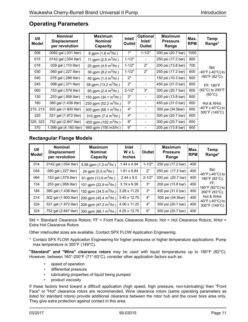
Check Belt and Chain Drive Alignment
Use a straight edge to visually check the belt or chain alignment. Keep the shaft distance to a minimum (Figure 24, item A).
After the piping is complete and before the belts are installed, manually turn the pump shaft to ensure it turns freely.
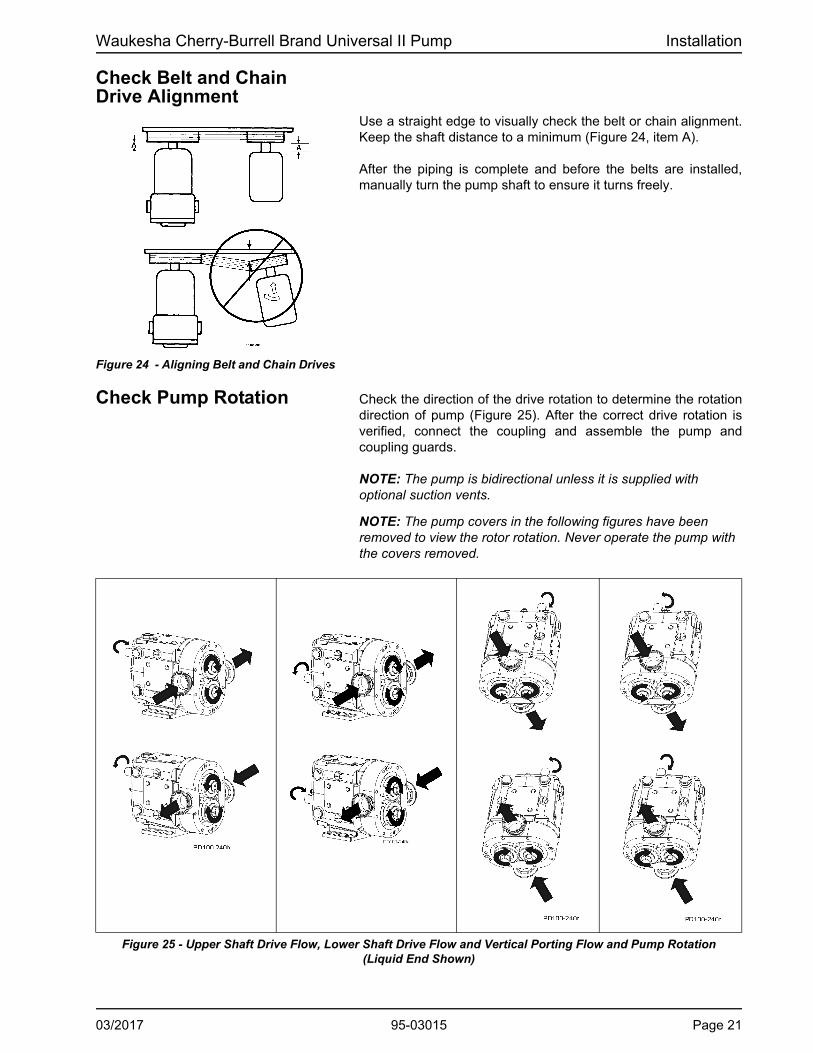
Check Pump Rotation Check the direction of the drive rotation to determine the rotation direction of pump (Figure 25). After the correct drive rotation is verified, connect the coupling and assemble the pump and coupling guards.
NOTE: The pump is bidirectional unless it is supplied with optional suction vents.
NOTE: The pump covers in the following figures have been removed to view the rotor rotation. Never operate the pump with the covers removed.
Figure 25 - Upper Shaft Drive Flow, Lower Shaft Drive Flow and Vertical Porting Flow and Pump Rotation (Liquid End Shown)
Figure 24 - Aligning Belt and Chain Drives
03/2017 95-03015 Page 21

Operation Waukesha Cherry-Burrell Brand Universal II Pump
Page 22 95-03015 03/2017
Operation DANGER: The pump contains internal moving parts. DO NOT put hands or fingers into the pump body ports or drive area at any time during operation. To avoid serious injury, DO NOT install, clean, service, or repair the pump unless all power is off and locked out.
CAUTION: These pumps are positive displacement, low slip design and will be severely damaged if operated with closed valves in the discharge or inlet lines. The pump warranty is not valid for damages caused by a hydraulic overload from operation or start-up with a closed valve in the system.
Pre-Startup Checklist 1. Ensure that the pump is correctly installed as described in “Installation” on page 13. Review “Install Relief Valves” on page 16 and install relief valves as needed.
2. Check the coupling alignment. See “Check Coupling Align-ment” on page 20.
CAUTION: Do not use this pump to flush a newly-installed system. Severe damage may occur to the pump and system if the pump is used to flush the system. Remove the rotors during sys-tem flushing, to prevent debris from being trapped between the rotors and the pump body. This debris may damage the pump upon startup.
3. Ensure that the pump and piping are clean and free of foreign material such as welding slag, gaskets, etc.
4. Ensure that all piping connections are tight and leak-free. Where possible, check the system with non-hazardous fluid.
5. Ensure that the pump and drive are lubricated. See “Lubrica-tion” on page 23.
6. Ensure that all guards are in place and secure.
WARNING: Full guards must be installed to isolate the operators and maintenance personnel from the rotating components. Guards are provided as part of a complete pump and drive package. The gap between the pump body and gearcase is required for 3-A sani-tary standards.
7. Double mechanical seals require adequate supply and flow of clean flushing fluids.
8. Ensure that all valves are open on the discharge side and a free flow path is open to the destination.
9. Ensure that all valves are open on the inlet side and fluid can fill the pump. A flooded suction installation is recommended.
WARNING: Do not start a pump with seal flush unless the seal flush is installed and on.
10. Check the direction of pump and drive rotation to ensure that the pump will rotate in the proper direction. See “Check Pump Rotation” on page 21.
Startup Procedure 1. Start the pump drive. Where possible, start at a slow speed or jog.
CAUTION: .In order to avoid temperature shock after the introduction of hot product, stop the pump prior to, or immediately after filling with hot product. Once the hot product has filled the pumphead, allow 15 minutes for the pump fluid components to thermally expand, then re-start the pump.
2. For sanitary applications, sanitize the pump per customer requirements before putting the pump into service.
3. Check to make sure that the liquid is reaching the pump. If pumping does not begin and stabilize, check “Troubleshoot-ing” on page 51.
Shutdown Procedure 1. Shut off the power to the pump drive.
2. Shut off the supply and discharge lines.

Waukesha Cherry-Burrell Brand Universal II Pump Maintenance
Maintenance
Important Safety Information
DANGER: The pump contains internal moving parts. DO NOT put hands or fingers into the pump body ports or drive area at any time during operation. To avoid serious injury, DO NOT install, clean, service, or repair the pump unless all power is off and locked out.
Before detaching port connections to the pump:
• Close the suction and discharge valves.
• Drain the pump and clean or rinse, if necessary.
• Disconnect or shut off the electrical supply and lock out all power.
Lubrication Drive Lubrication
Refer to the manufacturer’s manual shipped with the drive for proper drive lubrication and frequency.
Gears
Gears are factory-lubricated with gear oil at the quantity shown in Table 1 on page 24. Change the oil every 750 hours. Aggressive washdown or extreme running conditions may require more frequent lubrication intervals.
When the pump is not running, the gear oil level is correct when the oil level is visible in the sight glass.
When the pump is running, the oil level may be difficult to see and may appear cloudy.
Universal pumps are shipped with the oil level at or slightly above the sight glass.
Gear Oil SpecificationISO Grade 320, SAE 140 or AGMA Number 6EP, part number 118402+. If food-grade oil is required, use part number 000140003+.
Bearings
Bearings are factory-lubricated with grease. Re-lubricate them at the quantity shown in Table 1 on page 24. Grease the bearings every 750 hours. Aggressive washdown or extreme running conditions may require more frequent lubrication intervals.
Excess grease will accumulate in the gear case and must be removed through the cleanout hole covered with a plastic plug (Figure 26, item 48).
Best practice is to clean out this area every time you grease the pump. Water can accumulate in the gearcase from condensation or from aggressive washdown. If water is found in the gearcase, clean out this area more frequently.
Bearing Lubricant GreaseNLGI Grade No. 2, EP, Lithium-based lubricant is standard, part number 118401+. If food-grade grease is required, use part number 000140002+.
Figure 26 - Lubrication Points
A. Upper Shaft Drive Pump (Standard)B. Lower Shaft Drive Pump (Optional)24D. Oil Drain Plug24F. Oil Fill Plug24L. Oil Level Check Plug, Sightglass48. Grease Clean-out Plug67. Grease Fittings
03/2017 95-03015 Page 23
Maintenance Waukesha Cherry-Burrell Brand Universal II Pump
Maintenance Inspections DANGER: The pump contains internal moving parts. DO NOT put hands or fingers into the pump body ports or drive area at any time during operation. To avoid serious injury, DO NOT install, clean, service, or repair the pump unless all power is off and locked out.
Detecting wear in the early stages can reduce repair costs and down time. A simple “look-feel” inspection of the pump during breakdown cleaning is recommended to detect signs of trouble at an early stage.
A detailed maintenance inspection should be scheduled annually. See “Annual Maintenance” on page 27.
Refer to the “Maintenance Inspection Chart” on page 26 for possible causes and solutions to common issues discovered during inspection.
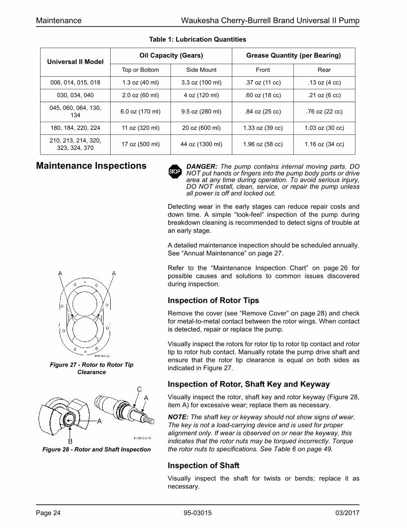
Inspection of Rotor Tips
Remove the cover (see “Remove Cover” on page 28) and check for metal-to-metal contact between the rotor wings. When contact is detected, repair or replace the pump.
Visually inspect the rotors for rotor tip to rotor tip contact and rotor tip to rotor hub contact. Manually rotate the pump drive shaft and ensure that the rotor tip clearance is equal on both sides as indicated in Figure 27.
Inspection of Rotor, Shaft Key and Keyway
Visually inspect the rotor, shaft key and rotor keyway (Figure 28, item A) for excessive wear; replace them as necessary.
NOTE: The shaft key or keyway should not show signs of wear. The key is not a load-carrying device and is used for proper alignment only. If wear is observed on or near the keyway, this indicates that the rotor nuts may be torqued incorrectly. Torque the rotor nuts to specifications. See Table 6 on page 49.
Inspection of Shaft
Visually inspect the shaft for twists or bends; replace it as necessary.
Table 1: Lubrication Quantities
Universal II ModelOil Capacity (Gears) Grease Quantity (per Bearing)
Top or Bottom Side Mount Front Rear
006, 014, 015, 018 1.3 oz (40 ml) 3.3 oz (100 ml) .37 oz (11 cc) .13 oz (4 cc)
030, 034, 040 2.0 oz (60 ml) 4 oz (120 ml) .60 oz (18 cc) .21 oz (6 cc)
045, 060, 064, 130, 134
6.0 oz (170 ml) 9.5 oz (280 ml) .84 oz (25 cc) .76 oz (22 cc)
180, 184, 220, 224 11 oz (320 ml) 20 oz (600 ml) 1.33 oz (39 cc) 1.03 oz (30 cc)
210, 213, 214, 320, 323, 324, 370
17 oz (500 ml) 44 oz (1300 ml) 1.96 oz (58 cc) 1.16 oz (34 cc)
Figure 27 - Rotor to Rotor Tip Clearance
Figure 28 - Rotor and Shaft Inspection
Page 24 95-03015 03/2017

Waukesha Cherry-Burrell Brand Universal II Pump Maintenance
Inspection of Rotor Hub End
Visually inspect the rotor hub end (Figure 28, item B) for excessive wear; replace it as necessary. Each time the rotors are removed, replace the o-rings on the hub.
Inspection of Shaft Shoulder
NOTE: Rotor hub and shaft shoulder wear are caused by operating with a loose rotor nut(s) for extended periods.
Visually inspect the shaft shoulder (Figure 28, item C) for excessive wear; replace it as necessary. If the shaft shoulder has a sharp edge, remove the edge with a file to prevent cutting the shaft o-ring on installation
Inspection of Gears and Bearings
Gear backlashWith the fluid head and seals removed, feel for gear backlash by rotating either shaft by hand. The other shaft must engage immediately. Perform this check three times at 60-degree intervals. If play (backlash) is evident, remove the gear case cover, check the gear teeth for wear, and ensure that the gear is not loose on the shaft. If the gear teeth are worn, replace the gears. If the gear is loose on the shaft, inspect the shaft key and keyway; replace as necessary.
Check bearing conditionWith the fluid head and seals removed, check the bearing condition by applying (by hand) an up or down force of approximately 30 lbs (14 kg). If movement is detected, the bearing may be failing. Also check the shaft movement forward or backward. If the bearing is failing, replace the bearing and review the lubrication section starting on page 23.
Figure 29 - Backlash Check
Figure 30 - Bearing Deflection Check
03/2017 95-03015 Page 25

Maintenance Waukesha Cherry-Burrell Brand Universal II Pump
Maintenance Inspection Chart
.
Problem Possible Causes Possible Solutions
Rotor tip to rotor tip contact or uneven rotor tip to rotor tip clearance.
Hard object jammed into rotors and twisted shafts.
Replace shafts. Install strainers if necessary. Check and replace gears if necessary.
Rotor tip to rotor hub contact.
Loose rotor nut(s). Belleville-style washer(s) on backwards. Backface clearances not even. Bearings need replacing.
Torque rotor nut(s) properly. Install belleville-style washers correctly. Verify backface clearances are even. Check and replace bearings.
Worn rotor or shaft keyway(s). Worn or damaged rotor key(s).
Loose rotor nut(s). Belleville-style washer(s) on backwards.
Replace rotors, shafts and keys. Torque rotor nut(s). See “Torque Values” on page 49. Install belleville-style washer(s) correctly.
Worn rotor hub end or shaft shoulder.
Loose rotor nut(s). Belleville-style washer(s) on backwards. Rotors slammed against shoulder when installed.
Torque rotor nut(s). See “Torque Values” on page 49. Install belleville-style washer(s) correctly. Replace rotors and shafts or shim front bearing(s) to maintain proper backface clearances.
Sharp edged shaft shoulder.
Loose rotor nut(s). Belleville-style washer(s) on backwards. Rotors slammed against shoulder when installed. Backface clearances not even.
Torque rotor nut(s). See “Torque Values” on page 49. Install belleville-style washer(s) correctly. Remove sharp edge with file to prevent cutting shaft o-ring. Verify backface clearances are even.
Gear backlash. Lack of lubrication. Excessive hydraulic loads. Loose gear locknuts.
Check lubrication level and frequency. Reduce hydraulic loads. Torque locknuts to specified torque values. See “Torque Values” on page 49. Check and replace gears if necessary.
Worn or broken gear teeth.
Lack of lubrication. Excessive hydraulic loads. Loose gear locknuts.
Check lubrication level and frequency. Reduce hydraulic loads. Torque locknuts to specified torque values. See “Torque Values” on page 49. Check and replace gears if necessary.
Loose gears. Gear locknuts not torqued properly. Locking assembly not torqued properly. Worn gear key.
Torque gear nut to specified torque value. See “Torque Values” on page 49. Check and replace gears if necessary. Inspect gear key, shaft keyway and shaft, replace if necessary.
Loose bearings, axially or radially.
Lack of lubrication. Excessive hydraulic loads. Product or water contamination.
Check lubrication level and frequency. Reduce hydraulic loads. Ensure no excess grease build-up. Replace bearings if necessary.
Damaged front grease seals.
Seal may be old and worn. No grease on lips to lubricate. Shaft worn under seals.
Replace seals. Properly lubricate with grease when installing. Inspect shaft surface under seals.
Damaged rear oil seals.
Seal may be old and worn. No grease on lips to lubricate. Shaft worn under seals. Not centered on shaft when installed.
Replace seals. Properly lubricate with grease when installing. Inspect shaft surface under seals.
Page 26 95-03015 03/2017

Waukesha Cherry-Burrell Brand Universal II Pump Maintenance
Annual Maintenance DANGER: The pump contains internal moving parts. DO NOT put hands or fingers into the pump body ports or drive area at any time during operation. To avoid serious injury, DO NOT install, clean, service, or repair the pump unless all power is off and locked out.
At least annually, perform the procedures and corrective measures outlined in “Maintenance Inspections” on page 24, in addition to the following preventive maintenance:
• Check the bearings with a dial indicator for shaft radial play. If the deflection is equal to or greater than the rotor-to-body diametrical clearance (“Checking for Proper Clearance” on page 40), replace the bearings.
• Remove the gear cover and inspect the gears for wear, backlash and looseness. Loosen and torque the gear retaining nuts to the proper torque.
• Thoroughly inspect the rotors for worn keyways, hub wear and stress cracks (Figure 31, item A). Use the dye check method to detect any fatigue-type cracks at rotor stress points.
• Review the performance record on the pump, and check the radial and backface clearances to determine wear and effect on performance. Adjustment to the operating speed can compensate for wear in some applications.
CAUTION: When bearings or shafts are replaced in the field, take care to correctly position the shaft by shimming it to maintain sufficient running clearances between the rotor wing faces and the pump body faces (backface and cover face). It is important to hold the same backface dimension for both rotors to avoid crossover interference.
Cleaning Determine the pump cleaning schedule on-site for materials being processed and plant maintenance schedule. For CIP models, see “CIP (Clean-In-Place) Features” on page 19.
To disassemble the fluid head, see “Fluid Head Disassembly” on page 28. Remove and clean the cover o-ring, pump seals, and the rotor nut assembly. Inspect and replace them as necessary.
NOTE: Always replace the rotor nut o-rings and rotor hub o-rings when reassembling the pump. If the area behind these seals becomes soiled, contact SPX FLOW Application Engineering for a specific cleaning and sanitizing procedure validated to remove bacteria. If a chlorine solution (200 ppm available chlorine) is used, it should leave no residual deposits which would remain in the pump.
Also, acid cleaners have a much higher metal corrosion rate and pump parts should remain in acid cleaning solutions no longer than necessary. Any strong inorganic mineral-based acids that are harmful to your hands would be harmful to pump parts. See “Care of Component Materials” on page 9.
In applications where material can harden in the pump during shutdown, a CIP cleaning, flush or disassembly of the fluid head and manual cleaning is strongly recommended.
Figure 31 - Rotor Stress Points
03/2017 95-03015 Page 27

Maintenance Waukesha Cherry-Burrell Brand Universal II Pump
Fluid Head Disassembly DANGER: The pump contains internal moving parts. DO NOT put hands or fingers into the pump body ports or drive area at any time during operation. To avoid serious injury, DO NOT install, clean, service, or repair pump unless all power is off and locked out.
DANGER: To avoid serious injury, shut off and drain prod-uct from the pump prior to disconnecting the piping.
. Remove Cover
1. Remove the cover nuts (Figure 32, item 11) from the cover (Figure 32, item 1).Using a soft hammer, tap the cover (Fig-ure 32, item 2) off the body studs and dowel pins.
2. Place the cover on a protected surface with the finished sur-faces facing up.
3. Remove and inspect the cover o-ring (Figure 32, item 36).
PD100-049
145
26C26B
26 2
1136
26A926D 26E
Figure 32 - Exploded View of Fluid Head
1. Body2. Cover9. Rotor11. Cover Nut26. Rotor Nut26A. Rotor Nut O-ring*
26B. Belleville-style washer26C. Retainer O-ring26D. Rotor O-ring*36. Cover O-ring45. Body Retaining Cap Screw
* Discard the o-rings from the rotor and rotor nut; these are intended for one-time use only.
Universal II Wrench Size
Model Cover Nut
006, 014, 015, 0185/8"
030, 034, 040
045, 060, 064, 130, 1347/8"
180, 184, 220, 224
210, 213, 214, 320, 323, 324, 370
1"
Page 28 95-03015 03/2017

Waukesha Cherry-Burrell Brand Universal II Pump Maintenance
Remove Rotor Nut Assemblies
1. Use a blocking dowel to keep the rotors from turning when removing the rotor nuts.
NOTE: When working on a rotor, always use a dowel to block the rotor against the body, not against the other rotor. See Figure 33 and Figure 34.
Blocking Dowel Diameter
UII Model Dowel Dia.
006, 014, 015, 018 .75 in (19 mm)
030, 034, 040 1.00 in (25 mm)
045, 060, 064, 130, 134 1.50 in (38 mm)
180, 184, 220, 224 1.875 in (48 mm)
210, 213, 214, 320, 324, 370 2.00 in (51 mm)
NOTE: This dowel is not available from SPX FLOW. FDA-approved nylon in these sizes is readily available from supply houses.
2. Using a wrench, remove the rotor nuts, belleville-style wash-ers, rotor nut o-rings and rotor hub o-rings.:
Non-Marring Socket Tool for Rotor Nuts
Model UII Pumps Part Number
006, 014, 015, 018 126533+
030, 034, 040 126534+
045, 060, 064, 130, 134 126257+
180, 184, 220, 224 126535+
210, 213, 214, 320, 323, 324 126536+
PL5060-CH116
Remove Rotors
Using only your hands, remove the rotor with the hub overlapping the other rotor wing (Figure 35, item 9). Place the rotors in the up-turned cover to prevent damage to close-tolerance parts.
If the rotors cannot be removed by hand:
• Use plastic or hardwood dowels to pry out the rotors.
• Remove the body retaining cap screws. Tap the body forward and backward with a soft hammer to loosen the rotors.
• If necessary, use a puller. Use care with the puller or dowels to avoid damaging the rotors.
Figure 33 - Loosen Top Rotor
Figure 34 - Loosen Bottom Rotor
Figure 35 - Remove Overlapping Rotor First
03/2017 95-03015 Page 29

Maintenance Waukesha Cherry-Burrell Brand Universal II Pump
Remove Pump Body
1. Remove the two body retaining cap screws (Figure 36, item 45).
2. Using a plastic mallet, tap the body off the gear case, dowel pins and body studs.
3. Slide the body straight off the body studs to prevent damag-ing mechanical seal parts.
4. Place the body on a protected surface with seals facing up to protect the seals.
Remove Mechanical Seal
92
92
93
93
98 96 97 94
94
91
91
95
95PD100-08037
Figure 37 - Single (Bottom) and Double (Top) Mechanical Seal
1. Remove the stationary seals from the pump body, using care not to damage the seals on the three body pins.
2. Remove the mechanical seal springs and o-rings on the sta-tionary seals.
3. Inspect the three seal body pins for damage and repair or replace them as necessary. If the pins are loose, replace them with new ones.
4. Remove the rotary seal from each shaft. Use caution not to damage the seals during removal. Use a steady, even force behind the seal in multiple locations. After the rotary seals are removed, remove and replace the shaft o-rings. Before installing the new o-rings, inspect the shaft’s o-ring groove(s) for damage and repair or replace them if required.
5. Inspect the flats on the shaft shoulder and repair or replace the shafts if required.
Figure 36 - Location of Cap Screws
ModelBody
RetainingCap Screw
006, 014, 015, 0183/16"
030, 034, 040
045, 060, 064, 130, 134 1/4"
180, 184, 220, 224
5/16"210, 213, 214, 320, 323, 324, 370
37. Stop Pin91. Inner Seal O-ring92. Shaft O-ring93. Seal Seat94. Inner Seal
95. Inner Wave Spring96. Outer Seal O-ring97. Outer Wave Spring98. Outer Seal
Page 30 95-03015 03/2017

Waukesha Cherry-Burrell Brand Universal II Pump Maintenance
Gear Case Disassembly DANGER: To avoid serious injury, DO NOT install, clean, service, or repair the pump unless all power is off and locked out.
DANGER: To avoid serious injury, shut off and drain prod-uct from the pump prior to disconnecting piping.
Remove Gear Case Cover
1. Remove the oil drain plug (Figure 38, item 24D); drain the oil.
2. Remove the cap screws from the gear case (Figure 38, item33A).
3. Pull the cover (item 4) off the shaft extension. If the cover sticks, use a soft hammer to loosen it.
4. Remove the silicone sealant (item 25) from the gear case and cover.
5. Using an arbor press, remove the oil seal (item 12) from the cover. Discard the used oil seal.
6. Straighten the tab on the lock washers (Figure 39, item 39).
Remove Shaft
1. Prevent the shafts from turning by placing a wedge between the gears (Figure 40, item A). Use a spanner wrench or drift punch to remove the gear lock nut. The gears will be removed later.
Figure 38 - Remove Gear Case Cover
3. Gear Case4. Gear Case Cover12. Oil Seal24D. Oil Drain Plug24F. Oil Fill Plug
24L. Oil Level Check Plug, Sight glass
25. Silicone Sealant33A. Cap Screw
PD100-056
12
33A 4
3
24D
24F
24L25
Figure 39 - Straighten Lock Tab on Lock Washers
Figure 40 - Block Shaft Rotation
03/2017 95-03015 Page 31

Maintenance Waukesha Cherry-Burrell Brand Universal II Pump
2. Remove the front bearing retainer screws (Figure 41, item33B) and pull off the bearing retainers (item 32). (If a retainer is stuck, leave it in place; it will press out when the shaft is removed.)
3. Remove the silicone sealant (Figure 42, item A) from the bearing retainer and gear case.
NOTE: Protect the liquid end of the shafts by wrapping them with tape.
4. Place the gear case on an arbor press with the liquid end fac-ing down. Protect the shaft ends with a wood or plastic block (Figure 44, item C) and press the shafts out of the gear case.
5. Remove the gear spacers and gear keys from the shafts.
6. Remove the gears from the gear case.
7. Press out and discard the front bearing seals from the front bearing retainers. Clean and reuse the bearing isolators, if installed.
8. Remove the shims. If the shafts and bearings will be reused, identify the shims and bearings that belong with each shaft.
9. Press out and discard both rear oil seals in the gear case (Figure 43, item 13).
. 10. Use a hydraulic press and V-blocks (Figure 45, item B) to remove the bearings (items 15 and 16) and spacer (item 30)
NOTE: Make sure both ends of the shaft are protected when removing the shaft.
Figure 41 - Remove Bearing Retainers
Figure 42 - Remove Sealant from Retainer
Figure 43 - Remove Rear Oil Seals
Figure 44 - Press Shafts from Gear Case
Figure 45 - Remove Bearings From Shaft
Page 32 95-03015 03/2017

Waukesha Cherry-Burrell Brand Universal II Pump Maintenance
Shaft Assembly Front Bearing Assembly
NOTE: SPX FLOW now offers shaft assemblies with pressed-on bearings. See page 96.
SPX FLOW PD Precision Pumps require bearing assemblies with very tight internal tolerances. In fact, the internal tolerances of “off-the-shelf” bearings can be many times larger than required. Although they are considered in-spec in the bearing industry, they can cause internal damage within an SPX FLOW PD Pump.
SPX FLOW’s proprietary bearing “MATCHING” process starts with top quality bearing assemblies, then sorts, measures, pairs, grinds and adds spacers to them to ensure the matched bearing sets meet the required tight internal tolerances.
SPX FLOW bearings can be cross-referenced and appear to be the same, but competitive bearings are omitting the Matching process, which is imperative to achieve the required internal tolerances. Once a bearing set is matched, it must remain together as a set for the life of the pump, in order to maintain the tight internal tolerances.
NOTE: The following instructions cover the assembly of a six-piece front bearing assembly. For a four-piece assembly, only one spacer and cup is used.
1. Lubricate the front bearing area of the shaft (Figure 46, item 7, 8) with oil or grease. Place it upright in a hydraulic press with the liquid end down.
2. Unwrap the front bearing assembly.
NOTE: DO NOT interchange the parts of one bearing assembly with another. The parts are precisely matched during manufactur-ing and must be installed as a matched assembly. See Figure 47.
Figure 46 - Grease Shaft
Figure 47 - Bearing assembly
A. Lower Cone / Roller AssemblyB. Inner SpacerC. Lower CupD. Outer SpacerE. Upper CupF. Upper Cone / Roller Assembly
03/2017 95-03015 Page 33

Maintenance Waukesha Cherry-Burrell Brand Universal II Pump
3. Lift the lower cone and roller assembly (Figure 48, item A) out of the bearing stack and place it on the shaft with the radius facing down. Press it onto the shaft until it is seated against the shaft shoulder. Press only on the inner cone.
4. Place the inner spacer (Figure 49, item B) over the shaft onto the lower cone and roller assembly.
5. Place the lower cup (item C) over the lower cone and roller assembly, keeping the cup opening toward the assembly.
6. Place the outer spacer (item D) over the shaft and onto the lower cup.
7. Place the upper cup (Figure 50, item E) on top of the outer spacer.
8. Lubricate the remaining upper cone and roller assembly (Fig-ure 50, item F) with oil or grease and slip it over the shaft with the roller radius facing up. Press it onto the shaft and into the upper cup.
NOTE: Make sure all components are aligned before pressing. Press only on the inner cone.
9. Install the bearing spacer (Figure 51, item 30).
Figure 48 - Press Lower Cone onto Shaft
Figure 49 - Install Inner & Outer Spacer and Lower Cup
Figure 50 - Install Upper Cup & Upper Cone
Figure 51 - Install Bearing Spacer
Page 34 95-03015 03/2017

Waukesha Cherry-Burrell Brand Universal II Pump Maintenance
Rear Bearing Assembly
Models 006, 014, 015, 018, 030, 034 and 040 use a single ball bearing assembly for the rear bearing. All other models use a tapered roller bearing assembly similar to the front bearings.
NOTE: PD Pump shaft assemblies with pressed-on bearings are available. See page 96.
1. Unwrap the rear bearing assembly.
NOTE: DO NOT interchange the parts of one bearing assembly with another. These parts are precisely matched during manufacturing and must be installed as a matched assembly.
• For models with ball bearing assemblies: Lubricate the shaft inner bearing race with oil or grease. Press the bearing into place. The shielded side of the bearing fits against the bearing spacer. Press only on the inner race.
• For models with tapered roller bearing assemblies: Lubricate the shaft bearing area with oil or grease. Follow the “Front Bearing Assembly” procedures 33.
NOTE: Heating the bearings is NOT recommended. If bearings are heated, do not exceed 300°F (149°C).
Figure 52 - Rear Tapered Roller Bearing Assembly
03/2017 95-03015 Page 35

Maintenance Waukesha Cherry-Burrell Brand Universal II Pump
Gear Case Assembly Shimming
1. When installing the shafts in the gear case, shim behind the front bearing to achieve the proper backface clearance between the back of the rotors and the body. The backface clearance must be equal for both rotors to prevent the rotors from hitting each other during operation.
NOTE: Do not install bearing retainer sealant, gears, or gear locknuts until the correct shimming has been verified.
2. If the shafts and/or bearings do not need to be replaced and the shims are marked indicating the shaft and bear-ing they are matched with, a shim adjustment probably will not be necessary. Reuse the existing tagged shims, shafts and bearings in the same gear case bores.
3. If existing shims are lost and/or a standard shaft is used, determine the required shims from the chart.
4. If it is necessary to calculate the required shims for replacement shafts, bearings or both, refer to Figure 53and Figure 54; carry measurements and calculations to three decimal places (i.e. .059).
NOTE: Arrange with thicker shims on outside of the shim pack.
5. Determine the shim thickness required for the front bearing:
• Measure “B” in the gear case and “C” on the shaft (Figure 53).
• Measure “D” and “E” on the body (Figure 54).
• Determine the proper backface clearance. Refer to Table 2, “Rotor Clearances,” on page 41.
• Required Shims = Backface clearance - C + B + D - E.
6. Place the shims in the body, resting against the shoulder in the front bearing bore.
Figure 53 - Measure B and C Figure 54 - Measure D and E
Suggested Shims
UII Model Std Shaft Replace-
ment Shaft Shim
kit
006, 014, 015, 018
.113 in (2.87 mm)
.110 in (2.79 mm)
117889+
030, 034, 040
.105 in (2.27 mm)
.102 in (2.59 mm)
117890+
045, 060, 064, 130,
134
.093 in (2.36 mm)
.088 in (2.24 mm)
117891+
180, 184, 220, 224
.115 in (2.92 mm)
.110 in (2.79 mm)
117892+
210, 213, 214, 320, 324, 370
.125 in (3.18 mm)
.120 in (3.05 mm)
117893+
B. Front face of gear case to back of bearing boreC. Shaft shoulder to back of bearing raceD. Body thicknessE. Depth of rotor cavity
Page 36 95-03015 03/2017
Waukesha Cherry-Burrell Brand Universal II Pump Maintenance
Install Shaft
1. With the shims in place, install the shaft assembly in the front bearing bore with the fluid end facing up. Ensure that the shaft is installed in its original location.
NOTE: The shafts may need to be removed for a final shim adjustment.
2. Lubricate the outside diameter of the bearing.
3. Press the shaft into place until it is seated against the shim pack. Press only against the outer race of the bearing.
NOTE: A tube of the same diameter as the outer race of the bearing also can be used to press the shaft into place.
4. Temporarily secure the shaft/bearing in place with bearing retainers to aid in checking the clearances. DO NOT install silicone sealant at this time.
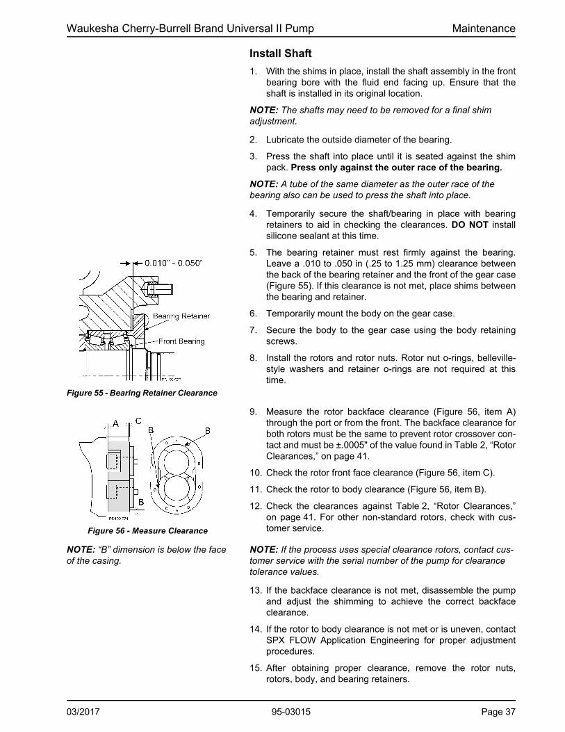
5. The bearing retainer must rest firmly against the bearing. Leave a .010 to .050 in (.25 to 1.25 mm) clearance between the back of the bearing retainer and the front of the gear case (Figure 55). If this clearance is not met, place shims between the bearing and retainer.
6. Temporarily mount the body on the gear case.
7. Secure the body to the gear case using the body retaining screws.
8. Install the rotors and rotor nuts. Rotor nut o-rings, belleville-style washers and retainer o-rings are not required at this time.
9. Measure the rotor backface clearance (Figure 56, item A) through the port or from the front. The backface clearance for both rotors must be the same to prevent rotor crossover con-tact and must be ±.0005" of the value found in Table 2, “Rotor Clearances,” on page 41.
10. Check the rotor front face clearance (Figure 56, item C).
11. Check the rotor to body clearance (Figure 56, item B).
12. Check the clearances against Table 2, “Rotor Clearances,” on page 41. For other non-standard rotors, check with cus-tomer service.
NOTE: “B” dimension is below the face of the casing.
NOTE: If the process uses special clearance rotors, contact cus-tomer service with the serial number of the pump for clearance tolerance values.
13. If the backface clearance is not met, disassemble the pump and adjust the shimming to achieve the correct backface clearance.
14. If the rotor to body clearance is not met or is uneven, contact SPX FLOW Application Engineering for proper adjustment procedures.
15. After obtaining proper clearance, remove the rotor nuts, rotors, body, and bearing retainers.
Figure 55 - Bearing Retainer Clearance
Figure 56 - Measure Clearance
03/2017 95-03015 Page 37
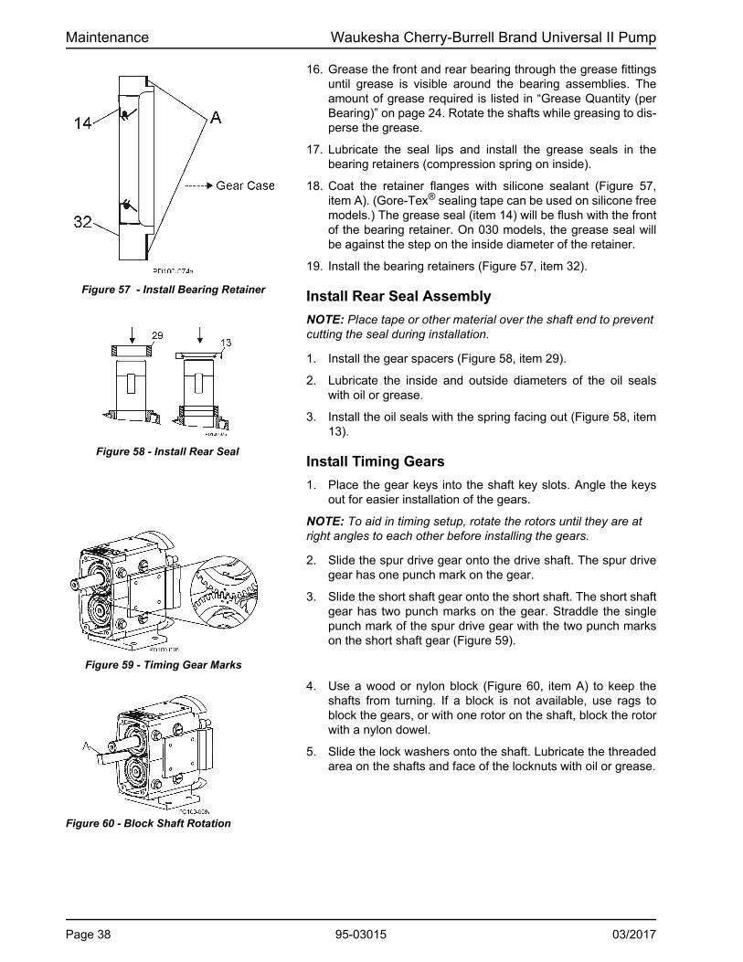
Maintenance Waukesha Cherry-Burrell Brand Universal II Pump
16. Grease the front and rear bearing through the grease fittings until grease is visible around the bearing assemblies. The amount of grease required is listed in “Grease Quantity (per Bearing)” on page 24. Rotate the shafts while greasing to dis-perse the grease.
17. Lubricate the seal lips and install the grease seals in the bearing retainers (compression spring on inside).
18. Coat the retainer flanges with silicone sealant (Figure 57, item A). (Gore-Tex® sealing tape can be used on silicone free models.) The grease seal (item 14) will be flush with the front of the bearing retainer. On 030 models, the grease seal will be against the step on the inside diameter of the retainer.
19. Install the bearing retainers (Figure 57, item 32).
Install Rear Seal Assembly
NOTE: Place tape or other material over the shaft end to prevent cutting the seal during installation.
1. Install the gear spacers (Figure 58, item 29).
2. Lubricate the inside and outside diameters of the oil seals with oil or grease.
3. Install the oil seals with the spring facing out (Figure 58, item13).
Install Timing Gears
1. Place the gear keys into the shaft key slots. Angle the keys out for easier installation of the gears.
NOTE: To aid in timing setup, rotate the rotors until they are at right angles to each other before installing the gears.
2. Slide the spur drive gear onto the drive shaft. The spur drive gear has one punch mark on the gear.
3. Slide the short shaft gear onto the short shaft. The short shaft gear has two punch marks on the gear. Straddle the single punch mark of the spur drive gear with the two punch marks on the short shaft gear (Figure 59).
4. Use a wood or nylon block (Figure 60, item A) to keep the shafts from turning. If a block is not available, use rags to block the gears, or with one rotor on the shaft, block the rotor with a nylon dowel.
5. Slide the lock washers onto the shaft. Lubricate the threaded area on the shafts and face of the locknuts with oil or grease.
Figure 57 - Install Bearing Retainer
Figure 58 - Install Rear Seal
Figure 59 - Timing Gear Marks
Figure 60 - Block Shaft Rotation
Page 38 95-03015 03/2017

Waukesha Cherry-Burrell Brand Universal II Pump Maintenance
6. Tighten the gear locknuts using a spanner wrench or drift.
7. Bend the locking tab on the lock washers into the locking nut slots, securing the gear locknut into place (Figure 62).
Figure 61 - Install Gear Locknuts
Figure 62 - Bend Lock Tab on Lock washers
03/2017 95-03015 Page 39

Maintenance Waukesha Cherry-Burrell Brand Universal II Pump
Checking for Proper Clearance
Waukesha Cherry-Burrell brand pumps are designed with close running clearances. Backface clearances are set with shims during assembly.
Shafts are positioned with shims behind the front bearing and locked into gear case with the bearing retainers. Rotors lock against the shaft shoulder. Clearance between the body backface and the back of the rotor wing is called backface clearance.
NOTE: It is generally best to keep backface clearance to a minimum.
1. To check backface clearance, first mount the body (less seals) onto the housing. Assemble the rotors and secure them with rotor jam nuts.
CAUTION: Backface clearance for both rotors must be equal to avoid crossover interference with the adjacent rotor hub.
2. With feeler gauges, measure the rotor backface clearance (Figure 63, item A), through the port or from the front.
Figure 63 - Clearance Measurements
Front BearingRearShim
BackfaceClearance
Rotor to BodyClearance
PumpBody
Front Face
A
B
CClearance
3. Measure the rotor front face clearance (Figure 63, item C).
4. Measure the rotor to body clearance (Figure 63, item B).
5. Check the measured clearances against Table 2, “Rotor Clearances,” on page 41.
6. Make corrections as required and follow examples in Table 3, “Backface Clearance Corrections,” on page 41, to determine the exact adjustment to make and to avoid unnecessary assembly/disassembly.
7. To make shim adjustments, first remove the rotors, body and shafts. Make the required shim adjustment and reassemble.
8. Re-check the backface clearances. Be sure both rotors have the same clearance to avoid crossover interference with the adjacent rotor hub.
Page 40 95-03015 03/2017

Waukesha Cherry-Burrell Brand Universal II Pump Maintenance
Table 2: Rotor Clearances
Universal II Model
Rotor Type: Std & FF Hot Std & FF Hot Standard FF & Hot0.0015 - 0.002 0.0015 - 0.002 0.001 - 0.004 0.0025 - 0.0055 0.004 - 0.006 0.0055 - 0.0075
(0.04 - 0.05) (0.04 - 0.05) (0.03 - 0.10) (0.06 - 0.14) (0.10 - 0.15) (0.14 - 0.19)0.0015 - 0.002 0.0015 - 0.002 0.001 - 0.004 0.0025 - 0.0055 0.004 - 0.0065 0.006 - 0.0085
(0.04 - 0.05) (0.04 - 0.05) (0.03 - 0.10) (0.06 - 0.14) (0.10 - 0.17) (0.15 - 0.22)0.002 - 0.0025 0.002 - 0.0025 0.001 - 0.005 0.0025 - 0.006 0.0035 - 0.006 0.0065 - 0.009
(0.05 - 0.06) (0.05 - 0.06) (0.03 - 0.13) (0.06 - 0.15) (0.09 - 0.15) (0.17 - 0.23)0.003 - 0.0035 0.003 - 0.0035 0.003 - 0.0075 0.005 - 0.010 0.0045 - 0.009 0.0085 - 0.014
(0.08 - 0.09) (0.08 - 0.09) (0.08 - 0.19) (0.13 - 0.25) (0.11 - 0.23) (0.22 - 0.36)0.003 - 0.0035 0.003 - 0.0035 0.0035 - 0.0075 0.0055 - 0.0095 0.0045 - 0.009 0.009 - 0.015
(0.08 - 0.09) (0.08 - 0.09) (0.09 - 0.19) (0.14 - 0.24) (0.11 - 0.23) (0.23 - 0.38)0.004 - 0.005 0.004 - 0.005 0.0055 - 0.0095 0.009 - 0.013 0.005 - 0.010 0.010 - 0.015 (0.10 - 0.13) (0.10 - 0.13) (0.14 - 0.24) (0.23 - 0.33) (0.13 - 0.25) (0.25 - 0.38)0.005 - 0.006 0.005 - 0.006 0.008 - 0.012 0.010 - 0.014 0.007 - 0.012 0.013 - 0.018(0.13 - 0.15) (0.13 - 0.15) (0.20 - 0.30) (0.25 - 0.36) (0.18 - 0.30) (0.33 - 0.46)0.005 - 0.006 0.005 - 0.006 0.009 - 0.013 0.011 - 0.015 0.007 - 0.012 0.013 - 0.018(0.13 - 0.15) (0.13 - 0.15) (0.23 - 0.33) (0.28 - 0.38) (0.18 - 0.30) (0.33 - 0.46)
Std = Standard Clearance Rotors; FF = Front Faced Clearance Rotors; Hot = Hot Clearance Rotors PD100-600a
Standard Rotors: -40°F (-40°C) to 180°F (82°C); FF Clearance Rotors: 180°F (82°C) to 200°F (93°C); Hot Clearance Rotors: -40°F (-40°C) to 300°F (149°C). Contact SPX FLOW Application Engineering if alternate rotors are needed. NOTE: The assembly clearances stated above are for reference only. Actual pump clearances may vary based on pump performance testing
A - Back Facein (mm)
B - Rotor to Bodyin (mm)
C - Front Facein (mm)
006
014, 015, 018
030, 034, 040
045, 060, 064
130, 134
180, 184, 220, 224
210, 213, 214, 320, 323, 324
370
.
Table 3: Backface Clearance Corrections
Problem Condition Correction
Too Much Backface Clearance (A)
Dimension A is greater than the value in Table 2.
A (measured) minus Column A (Table 2) = shims to remove from the rear outer race of the front bearing
Rotor wing face projects past the body front face
C (measured with depth micrometer) plus C (Table 2) = shims to remove from the rear of the front bearing
Not Enough Backface Clearance (A)
Dimension A is less than the value in Table 2.
Column A (Table 2) minus A (measured) = shims to add to the rear outer race of the front bearing
NOTE: If the clearance corrections in Table 3 have been performed and desired performance is not achieved, contact SPX FLOW technical services for guidance.
03/2017 95-03015 Page 41

Maintenance Waukesha Cherry-Burrell Brand Universal II Pump
Install Gear Case Cover
1. Lubricate the inside diameter of a new oil seal.
2. Press the new oil seal (Figure 64, item 12) into the gear case cover (item 4) flush with the outside face, with the spring fac-ing in.
3. Apply silicone sealant to the back of the gear case. (Gore-Tex® sealing tape can be used on silicone-free models.) Place tape on the inside of the screw holes. (Figure 65, item A).
4. Tape the shaft end to prevent cutting the seal on the keyway. Mount the cover assembly on the gear case. Secure it with cap screws and washers.
5. Remove the tape from the shaft end.
NOTE: Make sure that the shaft is centered in the lip seal before securing the cap screws.
6. Install the oil drain plug.
7. Fill gear case with gear oil to proper level. Refer to “Lubrica-tion” on page 23.
Figure 64 - Orientation of Oil Seal
Figure 65 Sealant Placement
Page 42 95-03015 03/2017

Waukesha Cherry-Burrell Brand Universal II Pump Maintenance
Fluid Head Assembly Install Mechanical Seal
92
92
93
93
98 96 97 94
94
91
91
95
95PD100-08037
Figure 66 - Single (Bottom) and Double (Top) Mechanical Seal
1. Lubricate the shaft o-ring (Figure 67, item 92) with a lubrica-tion compound compatible with the o-ring material and pro-cess fluid(s). Place the o-ring on the shaft.
2. Install the rotating seal seat (item 93) on the shaft. Align the drive flats on the seat with the drive flats on the shaft.
3. Push the seat squarely against the shaft shoulder.
4. Install the inner wave spring (item 95) onto the inner seal (item 94).
5. Lubricate the inner seal o-ring (item 91) with a lubrication compound compatible with the o-ring material and process fluid(s). Install the inner seal o-ring into the groove of the inner seal.
6. Place the inner seal into the back of the pump body. Ensure that the notches are aligned in the inner seal with the stop pins in the body. Press firmly and evenly into place.
7. If a double mechanical seal is used, install the outer wave spring (Figure 68, item 97) in the body and the outer o-ring (item 96) in the outer seal groove (item 98). Place the outer seal in the pump body around the inner seal, aligning the notches in the outer seal with the stop pins in the body.
8. Inspect the seal faces for cleanliness. Ensure that the faces have no nicks or scratches. Lubricate the seal faces with a lubricant compatible with the process fluid(s).
9. Perform steps 1 through 5 on both shafts.
37. Stop Pin91. Inner Seal O-ring92. Shaft O-ring93. Seal Seat94. Inner Seal
95. Inner Wave Spring96. Outer Seal O-ring97. Outer Wave Spring98. Outer Seal
Figure 67 - Single Mechanical Seal
Figure 68 - Double Mechanical Seal
03/2017 95-03015 Page 43

Maintenance Waukesha Cherry-Burrell Brand Universal II Pump
Figure 69 - Exploded View of Fluid Head
Install Pump Body
1. Match the large and small dowel pin sizes on the pump body with the dowel pin holes in the pump gear case.
2. Install the body (Figure 69, item 1) to the gear case assem-bly, aligning the body with the body studs. Avoid damaging the seals as the body is drawn over the shafts.
3. Secure the body to the gear case using two cap screws (Fig-ure 69, item 45).
Install Rotors
1. Lubricate the rotor hub o-ring (Figure 69, item 26D) with a lubrication compound compatible with the o-ring material and process fluid(s).
2. Install new rotor hub o-rings (item 26D) into the groove on the rotor hubs.
3. Install the rotors (item 9) onto the shafts.
4. Align the keyways in the rotors with the keyways on the shafts and install the keys (item 26E).
NOTE: For rotor nut assembly detail, including orientation of the belleville-style washer (item 26B), see Figure 70 and Figure 71 on page 45.
1. Body2. Cover9. Rotor11. Cover Nut26. Rotor Nut26A. Rotor Nut O-ring*
26B. Belleville-style Washer26C. Retainer O-ring26D. Rotor Hub O-ring*26E. Rotor Key36. Cover O-ring45. Body Retaining Cap Screw
* Discard rotor nut and rotor hub o-rings; these are one-time use only.
Page 44 95-03015 03/2017

Waukesha Cherry-Burrell Brand Universal II Pump Maintenance
Install Rotor Nut Assemblies
See Figure 69 on page 44, and Figure 70 and Figure 71 on this page.
1. Install a belleville-style washer (item 26B) into the rotor nut (26) with the raised side of the washer facing toward the rotor nut.
2. Place the retainer o-ring (item 26C) into the rotor nut to retain the belleville-style washer. The washer should not be tight against the o-ring.
3. Lubricate a new rotor nut o-ring (item 26A) with a lubrication compound compatible with the o-ring material and process fluid(s). If the o-ring is not lubricated, it will pucker when tight-ening the rotor nut.
4. Install the rotor nut o-ring onto the rotor nut.
5. Prior to assembling the rotor nuts, apply an anti-seize com-pound to the shaft threads.
6. Use a blocking dowel to prevent the rotors from turning dur-ing installation. See “Blocking Dowel Diameter” on page 29for rotor blocking dowel size.
NOTE: Always use a dowel to block the rotor against the body, not against the other rotor.
7. Screw the rotor nuts (item 26) onto the shafts (clockwise) and tighten them to the required torque.
CAUTION: Use a torque wrench to tighten the rotor nuts to proper torque. (See page 49 for torque values.) Failure to tighten nuts properly could result in the nuts loosening dur-ing operation, causing damage to the pump.
Install Cover
1. Clean the cover o-ring (See Figure 69 on page 44, item 36) and install it in the groove in the cover.
2. Match the large and small dowel pin sizes on the pump body with the dowel pin holes in the cover.
3. Install the cover (See Figure 69 on page 44, item 2) on the pump body.
4. Prior to assembling the cover nuts, apply an anti-seize com-pound compatible with the product to the threads of the body studs.
5. Tighten the cover securely using the cover nuts (See Figure 69 on page 44, item 11). (See page 49 for torque values)
CAUTION: Failure to tighten the cover nuts to the proper torque (See page 49) could cause the body studs to fail prematurely under high pressure.
CAUTION: If a double seal arrangement is used, the seals must be provided with a clean, compatible barrier fluid. Make certain that the flush ports in the pump body are clean and clear.
Figure 70 - Detail View of Rotor Nut Assembly
26C26B 2626A
PD100-544
Figure 71 - Cross-Section View of Rotor Nut Assembly, as Assembled
26C
PD100-545
2626A
26B
03/2017 95-03015 Page 45

Maintenance Waukesha Cherry-Burrell Brand Universal II Pump
Relief Cover Option (Vented Cover)
The optional Relief Cover Feature (also called Vented Cover) is an adjustable, internal by-pass arrangement which can be used for control of the pressure and/or flow. It is bidirectional; that is, the pump flow or rotation can be in either direction.
This option does not provide full flow relief for all pumping situations. The pressure downstream of the pump may increase with increasing amount of by-pass through the Relief Cover. Actual downstream pressure will depend on the pump speed, product viscosity, and the relief set point (spring adjustment or air pressure). Avoid high flow rates through the cover with high viscosity products. The resulting pressure may be greater than the maximum rating of the pump or other system components. Install a pressure gauge and measure the pressure under the worst conditions of maximum flow and maximum viscosity to determine the maximum pressure for your process. Under any conditions, if there is a complete flow shut off downstream, stop the pump as soon as possible. Continued pump operation with the entire flow by-passing will rapidly build heat within the pump body. Contact SPX FLOW Application Engineering for assistance.
NOTE: The vented cover is not CIP-able. It must be manually disassembled for cleaning.
Three types of Relief Covers are available:
Manual
By-pass pressure is adjusted by a threaded adjusting screw (2) which compresses a spring (5). Several spring sizes are available, to cover a range of operating pressures.
Pneumatic Diaphragm
By-pass pressure is adjusted by regulated air or gas pressure, operating on the side of a diaphragm (9) opposite the pumped fluid.
Pneumatic Piston
By-pass pressure is adjusted by regulated air or gas pressure, operating on the side of a metal piston (12), opposite the pumped fluid. An extended pressure range is possible.
NOTE: On all types of relief covers, the temperature and chemical resistance of the elastomer diaphragms and O-rings determine the useful range: Buna-N: Material supplied as standard Silicone Rubber: Optional material upon request
Figure 72 - Manual Vented Cover
Figure 73 - Pneumatic Vented Cover
Figure 74 - Piston Vented Cover
Page 46 95-03015 03/2017

Waukesha Cherry-Burrell Brand Universal II Pump Maintenance
Installation Adjustment
Manual
Turn the adjusting screw counterclockwise to its farthest position, then clockwise until a light spring pressure is felt.
Pneumatic Diaphragm
1. Set air/gas pressure to 2-5 psig.
2. Turn on the pump.
A. With the pressure gauge and valve in the discharge line:
• Close the discharge valve.
• Turn the adjusting screw clockwise until the desired relief pressure registers on the gauge. Lock the adjusting screw with a lock nut.
• Open the valve in the discharge line. The relief cover is set and will open if the system pressure exceeds the preset limit.
B. Without a pressure gauge in the discharge line:
• Turn the adjusting screw clockwise and observe the product flow at the discharge of the system.
When the product flow reaches the maximum or desired flow rate, lock the adjusting screw with a lock nut.
Pneumatic Piston
1. With a pressure gauge and valve in the discharge line:
• Close the discharge valve slowly and observe the gauge pressure. DO NOT ALLOW PRESSURE TO EXCEED 200 psi.
• Increase the air/gas pressure, until the desired relief pressure registers on the gauge. Lock the air/gas pressure regulator adjusting screw with a lock nut.
• Open the valve in the discharge line.The relief cover is set and will open if the system pressure exceeds the preset limit.
2. Without a pressure gauge in the discharge line:
• With a regulator, increase the air/gas pressure to the relief valve and observe the product flow at the discharge of the system.
When the product flow reaches a maximum or desired flow rate, lock the regulator adjusting screw with a lock nut.
Figure 75 - Manual Adjustment
Figure 76 - Adjustment with a Pressure Gauge
03/2017 95-03015 Page 47

Maintenance Waukesha Cherry-Burrell Brand Universal II Pump
Jacketed Cover The jacketed cover is designed to allow circulation of a heating or cooling medium. The purpose is to help preheat or cool the pumping head and sustain operating temperature during short shutdown periods. It should not be used as a heat exchanger to control pumping temperature during operation. The temperature rating is dependent on the rotor selection. See Table 2, “Rotor Clearances,” on page 41.
NOTE: Pressure limit for cover media is 60 PSI.
NOTE: Jacketed covers require longer mounting studs in the gear case.
Low Pressure Flush
1. Set flow rate of approximately 1/4 GPM for most applications. For high temperature applications, increase flow. (See “Universal II High-Pressure Barrier (HPB) Seals” on page 18.)
2. The flush media (water or lubricating fluid compatible with the product) must be connected and flowing whenever the pump is operated. Flushing media is restricted on the inlet side and has free flow to drain on the outlet side.
3. Typical flushing connections are 1/8" NPT female pipe taps.
See also “Seal Flush Connections” on page 17 and “Universal II High-Pressure Barrier (HPB) Seals” on page 18.
Flushing Connection - Aseptic Series
All connections are 1/8" female pipe taps. The pump has double "barriers" or seals at every opening to the pump chamber. Live steam or a sterile fluid is circulated between these double seals at the ports, in the cover and at the shaft seals.
Figure 78 - Flushing Connection - Aseptic Series
Steam In
Steam In
Steam InSteam
In
Steam Out
Steam Out
Steam Out
Steam Out
Figure 77 - Jacketed Cover
Table 4: Pipe Tap
Model Number Pipe Tap
006, 014, 015, 018, 030, 034, 040
3/4"
045, 060, 064, 130, 134, 180, 184, 220, 224, 210, 213, 214, 320, 323, 370
1"
PD100-543
A
A
Page 48 95-03015 03/2017

Waukesha Cherry-Burrell Brand Universal II Pump Maintenance
Table 6: Torque Values
Model Gear Nut Rotor Nut Cover NutGear Nut Driver
Tool
006, 015, 01875 ft lbs102 N·m
50 ft lbs68 N·m
7 ft lbs10 N·m
109281+
030, 040100 ft lbs136 N·m
120 ft lbs 163 N·m
11 ft lbs 15 N·m
109282+
045, 060140 ft lbs 190 N·m
250 ft lbs 339 N·m
56 ft lbs 76 N·m
109283+
13025 ft lbs 34 N·m
180, 220230 ft lbs312 N·m
325 ft lbs441 N·m
110 ft lbs149 N·m
110304+
210, 213, 320, 323, 370320 ft lbs 434 N·m
375 ft lbs 508 N·m
158 ft lbs 214 N·m
114702+
Table 7: Arbor or Hydraulic Press Tonnage (Approximate)
ModelShaft Front Bearing Rear Bearing
IN OUT ON OFF ON OFF
006, 014, 015, 018 .25 .50 .50 1.00 .50 1.00
030, 034, 040 .25 1.00 .50 1.00 .50 1.00
045, 060, 064, 130, 134 .50 1.00 2.00 5.00 3.00 5.00
180, 184, 220, 224 .50 1.00 5.00 15.00 5.00 15.00
210, 213, 214, 320, 323, 324, 370
.50 1.00 5.00 2.00 5.00 2.00
Reference Tables
Table 5: Universal II Wrench Size
Model Rotor NutBody Retaining
Cap ScrewCover Nut
006, 014, 015, 018 15/16"3/16" 5/8"
030, 034, 040 1-1/4"
045, 060, 064, 130, 134 1-5/8" 1/4"7/8"
180, 184, 220, 224 2-1/4"
5/16"210, 213, 214, 320, 323, 324, 370
2-3/8" 1"
03/2017 95-03015 Page 49

Maintenance Waukesha Cherry-Burrell Brand Universal II Pump
Table 8: Standard O-Ring Selections, Descriptions and Color Codes for WCB Brand Pumps
Nitrile (Buna-N) (NBR)
Compound Color: Black
Color Code: Yellow
FDA Compliant to 21CFR177.2600
3A Sanitary
Silicone (Si)
Compound Color: Orange
Color Code: Black
FDA Compliant to 21CFR177.2600
3A Sanitary
Ethylene Propylene Diene Rubber (EPDM)
Compound Color: Black or Purple
Color Code: Green
FDA Compliant to 21CFR177.2600
Perfluoroelastomer (FFKM)
Compound Color: Black
Color Code: None
Individually packaged with size and material noted.
Ethylene Propylene Diene Rubber (Sulfur Free) (EPDM)
Compound Color: Black or Purple
Color Code: Blue
FDA Compliant to 21CFR177.2600
PTFE Encapsulated
Compound Color: Translucent coating over Orange or Black Silicone or FKM core
Color Code: None
FDA Compliant to 21CFR177.2600
Fluorocarbon Rubber (FKM)
Compound Color: Rust, Brown or Black
Color Code: White
FDA Compliant to 21CFR177.2600
3A Sanitary
Page 50 95-03015 03/2017

Waukesha Cherry-Burrell Brand Universal II Pump Troubleshooting
Troubleshooting
PROBLEM POSSIBLE CAUSE SUGGESTED ACTION
No flow, pump rotors are not turning
Drive motor not running. Check resets, fuses, circuit breakers.
Keys sheared or missing. Replace.
Drive belts, power transmission components slipping or broken.
Replace or adjust.
Pump shaft, keys, or gears sheared.
Inspect: and replace parts as necessary.
No flow, pump rotors are turning
Rotors turn in the wrong direction.
Check motor hookup to reverse motor rotation.
Relief valve not properly adjusted, or held open by foreign material.
Adjust or clear valve.
Suction port is blocked, not allowing flow to the pump.
Check all inlet valves, strainers, tank outlet ports.
No flow, pump not priming Valve closed in inlet line. Open valve.
Inlet line clogged or restricted. Clear line, clean filters, etc.
Air leaks due to bad gaskets or pipe connections.
Replace gaskets; check lines for leakage (can be done by air pressure or by filling with liquid and pressurizing with air).
Pump speed too slow. Increase pump speed.
Pump speed too fast for high-viscosity liquid.
Decrease pump speed.
Liquid drains or siphons from system during off periods.
Use foot valve or check valves.Filling inlet lines with material before startup may solve startup priming problems due to no material in system.
"Air" lock caused by fluids which "gas off", or vaporize, or allow gas to come out of solution during off periods.
Install and use a manual or automatic air bleed from pump or lines near pump.
Extra clearance rotors, worn pump.
Increase pump speed, use foot valve to improve priming.
Replace worn rotors.
Net inlet pressure available too low.
Check Net Inlet Pressure Available & Net Inlet Pressure Required. Change inlet system as needed.
03/2017 95-03015 Page 51

Troubleshooting Waukesha Cherry-Burrell Brand Universal II Pump
PROBLEM POSSIBLE CAUSE SUGGESTED ACTION
No flow, pump not priming, cont’d
On "Vacuum'' inlet system: On initial start-up, atmospheric "blow back'' prevents pump from developing enough differential pressure to start flow.
Install check valve in discharge line.
Insufficient flow Speed too low or too high to obtain desired flow.
Check flow-speed curve (available from SPX FLOW website) and adjust as necessary.
Air leak due to bad seals, pipe connections, or other equipment.
Replace seals, check inlet fittings.
Insufficient flow—flow being bypassed somewhere
Flow diverted in branch line, open valve, etc.
Check system and controls
Relief valve not adjusted or jammed.
Clear or adjust valve.
Insufficient flow—high slip Hot (HC) or extra clearance rotors on "cold" fluid and/or low viscosity fluid.
Replace with standard clearance rotors.
Worn pump. Increase pump speed (within limits). Replace rotors, have pump remanufactured.
High pressure. Reduce pressure by adjusting system settings or hardware.
Fluid vaporization (“starved'' pump inlet)
Strainers, foot valves, inlet fittings or lines clogged.
Clear lines. If problem continues, inlet system may require changing.
Inlet line size too small, inlet line too long. Too many fittings or valves. Foot valve, strainers too small.
Increase inlet line size. Reduce length, minimize direction and size changes, reduce number of fittings.
NIPA - Net Inlet Pressure Available at Pump is too low.
Raise liquid level in source tank to increase Net Inlet Pressure (NIPA).
Increase Net Inlet Pressure Available at Pump by raising or pressurizing source tank.
Select larger pump size with lower Net Inlet Pressure Required.
Fluid viscosity greater than expected.
Reduce pump speed and accept lower flow, or change system to reduce line losses.
Change temperature of product to reduce viscosity.
Page 52 95-03015 03/2017

Waukesha Cherry-Burrell Brand Universal II Pump Troubleshooting
PROBLEM POSSIBLE CAUSE SUGGESTED ACTION
Fluid vaporization, cont’d Fluid temperature higher than expected (vapor pressure higher).
Reduce temperature, reduce speed and accept lower flow or change system to increase Net Inlet Pressure Available.
Noisy operation Cavitation
High fluid viscosity. High vapor pressure fluid. High temperature.
Slow down pump, reduce temperature, change system setup.
Net Inlet Pressure Avail-able less than Net Inlet Pressure Required.
Increase NIPA - Net Inlet Pressure Required or reduce NIPR - Net Inlet Pressure Required. Contact SPX FLOW if necessary.
Air or gas in fluid
Leaks in the pump or piping.
Correct leaks.
Dissolved gas or naturally aerated products.
Minimize discharge pressure (also see "Cavitation," above).
Noisy operation caused by mechanical problems
Rotor to body contact
Improper assembly of pump.
Check clearances and adjust shimming.
Distortion of pump due to improper piping installa-tion.
Change piping installation to eliminate piping stress and distortion on body.
Pressures required higher than the pump is rated for.
Reduce discharge pressure required.
Worn bearings. Rebuild with new bearings and lubricate regularly.
Rotor to Rotor Contact
Loose or incorrectly-timed gears.
This has caused severe damage to components - rebuild with new parts.
Sheared keys. This has caused severe damage to components - rebuild with new parts.
Worn gear splines. This has caused severe damage to components - rebuild with new parts.
Drive noise caused by gear trains, chains, couplings, bearings.
Repair or replace drive parts. Check bearings for damage and replace as necessary.
03/2017 95-03015 Page 53

Troubleshooting Waukesha Cherry-Burrell Brand Universal II Pump
PROBLEM POSSIBLE CAUSE SUGGESTED ACTION
Pump requires excessive power (overheats, stalls, high current draw, breakers trip)
Higher than expected viscosity losses.
If within pump rating, increase drive size.
Higher than expected pressures.
Reduce pump speed. Increase line sizes.
Fluid is colder with a higher viscosity than expected.
Heat fluid, insulate lines or heat trace lines.
Increase line sizes.
Fluid sets in line and pump during shutdown.
Insulate lines or heat trace lines.
Install a “soft start” drive.
Install a recirculating bypass system.
Flush system with a nonsetting fluid.
Fluid builds up on pump surfaces.
Replace the pump with more running clearances.
Short pump service life Pumping abrasives Larger pumps at slower speeds.
Speeds and pressures higher than rated.
Reduce speeds and pressures by making changes in the system.
Replace pump with a larger model with higher pressure ratings.
Worn bearings and gears due to lack of lubrication.
Check and replace bearing and gears as necessary. Adjust lubrication schedule to decrease time between lubrication.
Modify external wash down method to reduce water entering into gear case.
Misalignment of drive and piping. (Excessive overhung load or misaligned couplings.)
Check alignment of piping and drive. Adjust as necessary.
Page 54 95-03015 03/2017

Waukesha Cherry-Burrell Brand Universal II Pump Long Term Storage
03/2017 95-03015 Page 55
Long Term Storage Long-term storage (greater than six months) of Waukesha Cherry-Burrell brand pumps
Before Storage 1. Lubricate all bearings and seals, including:
• Rubber o-rings and mechanical seal faces (new pump bearings installed from the factory are already lubricated).
• Motors and drives (see manufacturer's instructions)
2. Be sure the pump contains no water. Make sure to disassemble the wet end and wipe it dry if necessary.
3. Use rust inhibitor on any exposed metal surfaces:
• Any unpainted surfaces
• Shafts, nuts/bolts
4. Cover the inlet/outlet connections of the pumps to keep out foreign materials.
5. Put all related instruction manuals in a separate water-tight envelope or container and store them with the equipment.
6. Completely enclose the equipment to prevent contamination from moisture, dust and other possible contaminants. Certain types of plastic wrap materials, when properly used, make excellent storage enclosures.
7. Rotate the pump and drive shafts several turns every 3 months.
Storage 1. Store in a dry location. Indoor storage is preferred. If stored outdoors, the equipment must be in a weather-tight enclosure and shielded from direct sunlight.
2. Maintain even temperatures to prevent condensation.
After Storage 1. Remove the equipment from the enclosure and repair or replace any damaged items before using equipment.
NOTE: Do not start the motor if there is any indication of water contamination. Have the motor checked by a qualified electrician before starting.
2. Check the electric motor (if applicable) per the manufacturer's instructions.
3. Pumps:
• Completely disassemble the product contact liquid end per the instruction manual.
• Clean and inspect all parts, including seals and o-rings.
• Replace rubber parts with any sign of age or damage, such as cracks, taking a set, or loss of elasticity.
4. Lubricate the seal and o-rings and reassemble the liquid end per the instruction manual.
5. Purge pump bearings with fresh grease.
6. Lubricate the motor/drive (if applicable) per the manufacturer's instructions.
7. If the pump has been in storage longer than 1 year, change the oil in the pump and drive.

Parts List Waukesha Cherry-Burrell Brand Universal II Pump
Parts List
006, 014, 015, 018-UII Pump Parts
1
26
23
26C26B
2
9
37 21
4520
26A
36
26D
11
22
3
15
17
12
33A
33C
513
4139
2448
10 34
30
4244
35 29
27
16
7
17 8
26E
32
25
PD100-345
25
33B
14
6
434665
66
47
9
136B 10A
Page 56 95-03015 03/2017
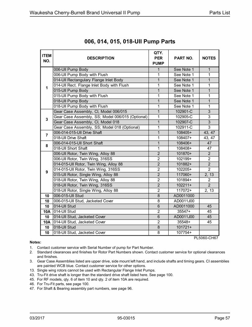
Waukesha Cherry-Burrell Brand Universal II Pump Parts List
006, 014, 015, 018-UII Pump Parts
ITEM NO.
DESCRIPTIONQTY. PER
PUMPPART NO. NOTES
006-UII Pump Body 1 See Note 1 1006-UII Pump Body with Flush 1 See Note 1 1014-UII Rectangulary Flange Inlet Body 1 See Note 1 1014-UII Rect. Flange Inlet Body with Flush 1 See Note 1 1015-UII Pump Body 1 See Note 1 1015-UII Pump Body with Flush 1 See Note 1 1018-UII Pump Body 1 See Note 1 1018-UII Pump Body with Flush 1 See Note 1 1Gear Case Assembly, CI, Model 006/015 1 102901-C 3Gear Case Assembly, SS; Model 006/015 (Optional) 1 102905-C 3Gear Case Assembly, CI, Model 018 1 102907-C 3Gear Case Assembly, SS; Model 018 (Optional) 1 102911-C 3006-014-015-UII Drive Shaft 1 108405+ 43, 47018-UII Drive Shaft 1 108407+ 43, 47006-014-015-UII Short Shaft 1 108406+ 47018-UII Short Shaft 1 108408+ 47006-UII Rotor, Twin Wing, Alloy 88 2 101870+ 2006-UII Rotor, Twin Wing, 316SS 2 102199+ 2014-015-UII Rotor, Twin Wing, Alloy 88 2 101882+ 2014-015-UII Rotor, Twin Wing, 316SS 2 102205+ 2015-UII Rotor, Single Wing, Alloy 88 2 117060+ 2, 13018-UII Rotor, Twin Wing, Alloy 88 2 101894+ 2018-UII Rotor, Twin Wing, 316SS 2 102211+ 2018-UII Rotor, Single Wing, Alloy 88 2 117072+ 2, 13
10 006-015-UII Stud 8 AD001100010 006-015-UII Stud, Jacketed Cover 8 AD0011J0010 014-UII Stud 6 AD0011000 45
10A 014-UII Stud 2 35547+ 4510 014-UII Stud, Jacketed Cover 6 AD0011J00 45
10A 014-UII Stud, Jacketed Cover 2 35548+ 4510 018-UII Stud 8 101721+10 018-UII Stud, Jacketed Cover 8 107754+
PL5060-CH67
1
8
9
7
3
Notes:
1. Contact customer service with Serial Number of pump for Part Number.2. Standard clearances and finishes for Rotor Part Numbers shown. Contact customer service for optional clearances
and finishes.3. Gear Case Assemblies listed are upper drive, side mount left hand, and include shafts and timing gears. CI assemblies
are painted WCB blue. Contact customer service for other options.13. Single wing rotors cannot be used with Rectangular Flange Inlet Pumps.43. Tru-Fit drive shaft is longer than the standard drive shaft listed here. See page 100.45. For RF models, qty. 6 of item 10 and qty. 2 of item 10A are required.46. For Tru-Fit parts, see page 100.47. For Shaft & Bearing assembly part numbers, see page 96.
03/2017 95-03015 Page 57

Parts List Waukesha Cherry-Burrell Brand Universal II Pump
006, 014, 015, 018-UII Common Parts
1
9
10
7
8
37
45
36
33A
33C
4139
48
34
30
4244
2935
27
17
32 PD100-343
33B
14
4365
66
47
26E
26
23
26C26B
2
21 20
26A
26D
11
22
3
15
17
12 4
5 13
24
16
2525 6
46
36B
Page 58 95-03015 03/2017

Waukesha Cherry-Burrell Brand Universal II Pump Parts List
.
ITEM NO.
DESCRIPTIONQTY. PER
PUMPPART NO. NOTES
Pump Cover 1 101842+Jacketed Cover 1 107664+Pump Cover Vented - Complete Assembly 1Gear Case Cover, Steel 1 020106000+Gear Case Cover, SS; Optional 1 102280+
5 Gear, Drive Shaft, Spur 1 107997+6 Gear, Short Shaft, Spur 1 107997+
Hex Nut 8 108369+Wing Nut; Optional 8 105850+
12 Oil Seal, Gear Case Cover 1 000030016+13 Oil Seal, Gear Case Rear 2 000030017+
Grease Seal, Bearing Retainer, standard gearcase 2 121679+ 3, 4Grease Seal, Bearing Retainer, SS Gearcase or Bearing Isolator
2 101716+ 4
15 Bearing, Rear 2 015035000+16 Bearing, Front 2 101714+17 Key, Gear 2 015037000+20 Dowel Pin, Upper Cover Side 1 137001+ 4321 Dowel Pin, Upper Gear Case Side 1 124581+ 4422 Dowel Pin, Lower Cover Side 1 137002+ 4323 Dowel Pin, Lower Gear Case Side 1 124582+ 44
Oil Plug, M20 x 1.5" 5 115798+ 40Oil Level Indicator, M20 x 1.5" 1 115799+Oil Level Indicator, ATEX, M20 x 1.5 1 131417+
25 Silicone Sealant 1 000142301+26 Nut, Rotor 2 101804+
O-Ring, Rotor Nut, Buna N 2 N70126O-Ring, Rotor Nut, EPDM 2 E70126O-Ring, Rotor Nut, FKM 2 V70126
26B Washer, Belleville 2 101691+O-Ring, Retainer, Buna N 2 N70112O-Ring, Retainer, EPDM 2 E70112O-Ring, Retainer, FKM 2 V70112O-Ring, Rotor Hub, Buna N 2 N70121O-Ring, Rotor Hub, EPDM 2 E70121O-Ring, Rotor Hub, FKM 2 V70121
PL5060-CH68
*
*
* 26D
2
4
26C
26A
11
14
24
006, 014, 015, 018-UII Common Parts
Notes:
* Recommended Spare Parts1. Please configure in E-Sales.3. Pumps manufactured prior to June 2004 use 000030018+ for the grease seal.4. Pumps with bearing isolators use 101716+ as the grease seal and 101810+ as the bearing retainer.
For bearing isolator kit, and pumps older than 7/12/04, see page 97.40. Applies to pumps shipped after October 2003. Pumps shipped prior to October 2003 used qty 6 of plug w/washer, part
number 000046002+.43. Exposed length of dowel pin: .444" (11.3 mm)44. Exposed length of dowel pin: .563" (14.3 mm)47. For Shaft & Bearing assembly part numbers, see page 96.
03/2017 95-03015 Page 59

Parts List Waukesha Cherry-Burrell Brand Universal II Pump
006, 014, 015, 018-UII Common Parts, cont’d
1
9
10
7
8
37
45
36
33A
33C
4139
48
34
30
4244
2935
27
17
32 PD100-343
33B
14
4365
66
47
26E
26
23
26C26B
2
21 20
26A
26D
11
22
3
15
17
12 4
5 13
24
16
2525 6
46
36B
Page 60 95-03015 03/2017

Waukesha Cherry-Burrell Brand Universal II Pump Parts List
006, 014, 015, 018-UII Common Parts, cont’d
ITEM NO.
DESCRIPTIONQTY. PER
PUMPPART NO. NOTES
006-014-015-UII Key, Rotor 2 101817+018-UII Key, Rotor 2 101819+
27 Shim Kit 2 117889+29 Spacer, Gear to Rear Bearing 2 015055000+30 Bearing Spacer 2 101814+
Bearing Retainer, Front SS, for standard gearcase 2 120332+ 4Bearing Retainer, Front SS, for SS Gearcase or Bearing Isolator
2 101810+ 4
33A, 33B 1/4-20 x .75" HHCS, SS 14 30-5833C 1/4" Flat Washer 6 43-2734 Dowel Bushing, Upper 1 AD011600035 Dowel Bushing, Lower 1 AD0116 100
O-Ring, Pump Cover, Buna N 1 N70249O-Ring, Pump Cover, EPDM 1 E70249O-Ring, Pump Cover, FKM 1 V70249014-UII O-Ring, Rectangular Flange, Buna N 1 N70241014-UII O-Ring, Rectangular Flange, EPDM 1 E70241014-UII O-Ring, Rectangular Flange, FKM 1 V70241
37 Stop Pin, Seal 6 101718+39 Lockwasher, Gear 2 STD13600541 Locknut, Gear 2 STD236005
Gear Case Shim, CI 1 020110000+Gear Case Shim, SS; Optional 1 102284+Pump Pedestal, 6.75", Optional 1 014110675+
43 Plastic Cap Plug 8 000121003+44 5/16-18 x 1" SHCS, SS 4 30-525
006-014-015-UII Body Retaining Screw, 1/4-20 x 1-1/4" 2 30-523018-UII Body Retaining Screw, 1/4-20 x 2" 2 30-211
46 Eye Bolt, 5/16-18 x .50" ZP 2 2 30-722Key, Coupling - 3/16 x 3/16 x 1-1/8" 1 000037001+Key, Coupling - Tru-Fit 1 119714+
48 Cleanout Plug 2 35824+ 1561 Name Plate, Sanitary 1 135623+62 #2 x .187” RHDS 4 30-35565 Caution Plate 2 121694+66 Warning Label 2 33-63
006-015-018-U1 Grease Fitting, 1/8" 4 BD0092000 2014-U1 Grease Fitting, 1/8" 4 BD0092100 3
68 Plastic Cap, Grease Fitting 4 BD0093000PL5060-CH69
47
26E
32
36
42
* 36B
*
45
67
Notes:
* Recommended Spare Parts2. This grease fitting is the straight style. Part number BD0092100 is the angled style.3. This grease fitting is the angled style. Part number BD0092000 is the straight style.4. 101810+ bearing retainer is used with 101716+ grease seal. For bearing isolator kit, and for pumps older than
7/12/04, see page 97.15. For an older gearcase without a threaded plug hole, use plug p/n 000121003+.16. For seals, see page 89.17. For vented covers, see page 98.
03/2017 95-03015 Page 61

Parts List Waukesha Cherry-Burrell Brand Universal II Pump
030, 034, 040-UII Pump Parts
.
1
26
23
26C26B
2
9
37 21
4520
26A
36
26D
11
22
3
15
17
12
33A
33C
513
4139
2448
10 34
30
4244
35 29
27
16
7
17 8
26E
32
25
PD100-345
25
33B
14
6
434665
66
47
9
136B 10A
Page 62 95-03015 03/2017

Waukesha Cherry-Burrell Brand Universal II Pump Parts List
030, 034, 040-UII Pump Parts
ITEM NO.
DESCRIPTIONQTY. PER
PUMP
PART NO.
NOTES
030-UII Pump Body 1 See Note 1 1030-UII Pump Body with Flush 1 See Note 1 1034-UII Rectangular Flange Inlet Body 1 See Note 1 1034-UII Rectangular Flange Inlet Body with Flush 1 See Note 1 1040-UII Pump Body 1 See Note 1 1040-UII Pump Body with Flush 1 See Note 1 1030-034-UII Gear Case Assembly, CI 1 102913-C 3030-034-UII Gear Case Assembly, SS; Optional 1 102917-C 3040-UII Gear Case Assembly, CI 1 120370-C 3040-UII Gear Case Assembly, SS; Optional 1 125943-C 3030-034 UII Drive Shaft 1 108409+ 43040 UII Drive Shaft 1 118722+ 43030-034 UII Short Shaft 1 108410+040-UII Short Shaft 1 118723+030-034-UII Rotor, Twin Wing, Alloy 88 2 102151+ 2030-034-UII Rotor, Twin Wing, 316SS 2 102217+ 2030-UII Rotor, Single Wing, Alloy 88 2 117084+ 2, 12, 13030-UII Rotor, Single Wing, 316SS 2 117088+ 2, 12A, 13040-UII Rotor, Twin Wing, Alloy 88 2 118766+ 2040-UII Rotor, Twin Wing, 316SS 2 118779+ 2040-UII Rotor, Single Wing, Alloy 88 1 124255+ 2, 13040-UII Rotor, Single Wing, 316SS 1 124268+ 2, 13
10 030-UII Stud 8 108842+10 030-UII Stud, Jacketed Cover 8 108845+10 034-UII Stud 6 108842+ 45
10A 034-UII Stud 2 35555+ 4510 034-UII Stud, Jacketed Cover 6 108845+ 45
10A 034-UII Stud, Jacketed Cover 2 35549+ 4510 040-UII Stud 8 118897+10 040-UII Stud, Jacketed Cover 8 118898+
PL5060-CH72
3
1
7
8
9
Notes:
1. Contact customer service with Serial Number of pump for Part Number.2. Standard clearances and finishes for Rotor Part Numbers shown. Contact customer service for optional clearances
and finishes.3. Gear Case Assemblies listed are upper drive, side mount left hand, and include shafts and timing gears. CI assemblies
are painted WCB blue. Contact customer service for other options.12. Replaces P/N 104707 (straight) and P/N 104836 (90 degree) rotors. 12A.Replaces P/N 104719 (straight) and P/N 104848 (90 degree) rotors.13. Single wing rotors cannot be used with Rectangular Flange Inlet Pumps.43. Tru-Fit drive shaft is longer than the standard drive shaft listed here. See page 100.45. For RF models, qty. 6 of item 10 and qty. 2 of item 10A are required.47. For Shaft & Bearing assembly part numbers, see page 96.
03/2017 95-03015 Page 63
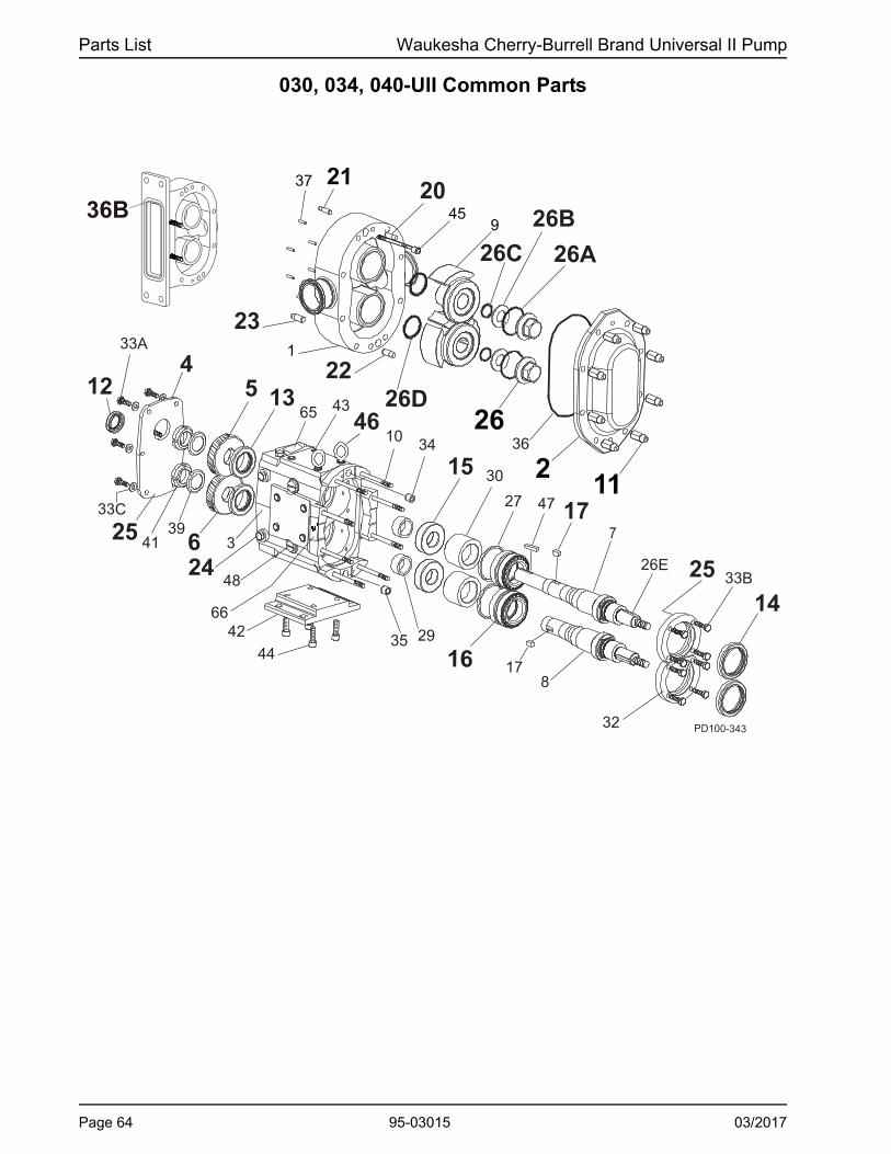
Parts List Waukesha Cherry-Burrell Brand Universal II Pump
030, 034, 040-UII Common Parts
1
9
10
7
8
37
45
36
33A
33C
4139
48
34
30
4244
2935
27
17
32 PD100-343
33B
14
4365
66
47
26E
26
23
26C26B
2
21 20
26A
26D
11
22
3
15
17
12 4
5 13
24
16
2525 6
46
36B
Page 64 95-03015 03/2017

Waukesha Cherry-Burrell Brand Universal II Pump Parts List
030, 034, 040-UII Common PartsITEM NO.
DESCRIPTIONQTY. PER
PUMPPART NO.
NOTES
Pump Cover 1 101845+Jacketed Cover 1 107666+Pump Cover Vented - Complete Assembly 1Gear Case Cover, Steel 1 040106000+Gear Case Cover, SS; Optional 1 102281+
5 Gear, Drive Shaft, Spur 1 107999+6 Gear, Short Shaft, Spur 1 107999+
Hex Nut 8 108370+Wing Nut; Optional 8 105851+
12 Oil Seal, Gear Case Cover 1 000030013+13 Oil Seal, Gear Case Rear 2 000030014+14 Grease Seal, Bearing Retainer 2 121680+ 215 Bearing, Rear 2 030035000+16 Bearing, Front 2 101715+17 Key, Gear 2 BD003700020 Dowel Pin, Upper Cover Side 1 137001+ 4321 Dowel Pin, Upper Gear Case Side 1 124582+ 4422 Dowel Pin, Lower Cover Side 1 137002+ 4323 Dowel Pin, Lower Gear Case Side 1 124583+ 44
Oil Plug, M20 x 1.5" 5 115798+ 40Oil Level Indicator, M20 x 1.5" 1 115799+ 40Oil Level Indicator, ATEX, M20 x 1.5 1 131417+
25 Silicone Sealant 1 000142301+26 Nut, Rotor 2 101805+
O-Ring, Rotor Nut, Buna N 2 N70130O-Ring, Rotor Nut, EPDM 2 E70130O-Ring, Rotor Nut, FKM 2 V70130
26B Washer, Belleville 2 101692+O-Ring, Retainer, Buna N 2 N70115O-Ring, Retainer, EPDM 2 E70115O-Ring, Retainer, FKM 2 V70115O-Ring, Rotor Hub, Buna N 2 N70127O-Ring, Rotor Hub, EPDM 2 E70127O-Ring, Rotor Hub, FKM 2 V70127
PL5060-CH73
*
*
*
11
24
2
4
26D
26A
26C
Notes:
* Recommended Spare Parts1. Please configure in E-Sales.2. Pumps manufactured prior to June 2001 use 000030015+ for the grease seal. See page 97.40. Applies to pumps shipped after October 2003. Pumps shipped prior to October 2003 used qty 6 of plug with washer,
part number 000046003+.43. Exposed length of dowel pin: .444" (11.3 mm) 44. Exposed length of dowel pin: .563" (14.3 mm)47. For Shaft & Bearing assembly part numbers, see page 96.
03/2017 95-03015 Page 65

Parts List Waukesha Cherry-Burrell Brand Universal II Pump
030, 034, 040-UII Common Parts, cont’d
1
9
10
7
8
37
45
36
33A
33C
4139
48
34
30
4244
2935
27
17
32 PD100-343
33B
14
4365
66
47
26E
26
23
26C26B
2
21 20
26A
26D
11
22
3
15
17
12 4
5 13
24
16
2525 6
46
36B
Page 66 95-03015 03/2017

Waukesha Cherry-Burrell Brand Universal II Pump Parts List
030, 034, 040-UII Common Parts, cont’d
ITEM NO.
DESCRIPTIONQTY. PER
PUMP
PART NO.
NOTES
* 26E Key, Rotor 2 101821+27 Shim Kit 2 117890+29 Spacer, Gear to Rear Bearing 2 030055000+30 Bearing Spacer 2 101815+32 Bearing Retainer, Front SS, for std. lip seal 2 120333+ 3
33A 5/16-18 x 3/4" HHCS, SS 6 30-6235/16-18 x 3/4" BSHCS, STD 8 30-2965/16-18 x 3/4" SHCS, SS 8 30-29
33C 5/16" Flat Washer 6 43-24634 Dowel Bushing, Upper 1 BD011600035 Dowel Bushing, Lower 1 BD0116100
O-Ring, Pump Cover, Buna N 1 N70259O-Ring, Pump Cover, EPDM 1 E70259O-Ring, Pump Cover, FKM 1 V70259034-UII O-Ring, Rectangular Flange, Buna N 1 N70357034-UII O-Ring, Rectangular Flange, EPDM 1 E70357034-UII O-Ring, Rectangular Flange, FKM 1 V70357
37 Stop Pin, Seal 6 101719+39 Lockwasher, Gear 2 CD0036 W0041 Locknut, Gear 2 CD0036 N00
Gear Case Shim, CI 1 040110000+Gear Case Shim, SS; Optional 1 102285+Pump Pedestal, 6.25", Optional 1 BD0110SM0
43 Plastic Cap Plug, 3/8" 8 000121002+44 3/8-16 x 1" SHCS 4 30-189
030,034-UII Body Retaining Screw, 1/4-20 x 2" 2 30-211040-UII Body Retaining Screw, 1/4-20 x 2.5" 2 30-543
46 Eye Bolt, 3/8-16 x 1.0" ZP 2 2 30-723Key, Coupling - 1/4 x 1/4 x 1-3/4" 1 000037002+Key, Coupling - Tru-Fit 1 119715+
48 Cleanout Plug 2 41013+ 1561 Name Plate, Sanitary 1 135624+62 #2 x .187” RHDS 4 30-35565 Caution Plate 2 121694+66 Warning Label 2 33-63
030-UII and 040-UII Grease Fitting, 1/8" 4 BD0092000 1034-UII Grease Fitting, 1/8" 4 BD0092100 2
68 Plastic Cap, Grease Fitting 4 BD0093000PL5060-CH74
*
*
45
33B
36
42
47
67
36B
Notes:
* Recommended Spare Parts1. This grease fitting is the straight style. Part number BD0092100 is the angled style.2. This grease fitting is the angled style. Part number BD0092000 is the straight style.3. For bearing retainer for SS gearcase or for bearing isolator, for bearing isolator kit, and for pumps manufactured prior
to July 2004, see page 97.15. For an older gearcase without a threaded plug hole, use plug p/n 000121002+.16. For seals, see page 89.17. For vented covers, see page 98.47. For Shaft & Bearing assembly part numbers, see page 96.
03/2017 95-03015 Page 67

Parts List Waukesha Cherry-Burrell Brand Universal II Pump
045, 060, 064, 130, 134-UII Pump Parts
.
1
26
23
26C26B
2
9
37 21
4520
26A
36
26D
11
22
3
15
17
12
33A
33C
513
4139
2448
10 34
30
4244
35 29
27
16
7
17 8
26E
32
25
PD100-345
25
33B
14
6
434665
66
47
9
136B 10A
Notes: (See "Notes" column on page 69)
1. Contact customer service with Serial Number of pump for Part Number.2. Standard clearances and finishes for Rotor Part Numbers shown. Contact customer service for optional clearances
and finishes.3. Gear Case Assemblies listed are upper drive, side mount left hand, and include shafts and timing gears. CI assemblies
are painted WCB blue. Contact customer service for other options.12. Replaces (obsolete) P/Ns 104728 (straight) and 104857 (90 degree) rotors. 12A.Replaces (obsolete) P/Ns 104746 (straight) and 104875 (90 degree) rotors.13. Single wing rotors cannot be used with Rectangular Flange Inlet Pumps.43. Tru-Fit drive shaft is longer than the standard drive shaft listed here. See page 100.45. For RF models, qty. 6 of item 10 and qty. 2 of item 10A are required.46. For Tru-Fit parts, see page 100. For Shaft & Bearing assembly part numbers, see page 96.
Page 68 95-03015 03/2017
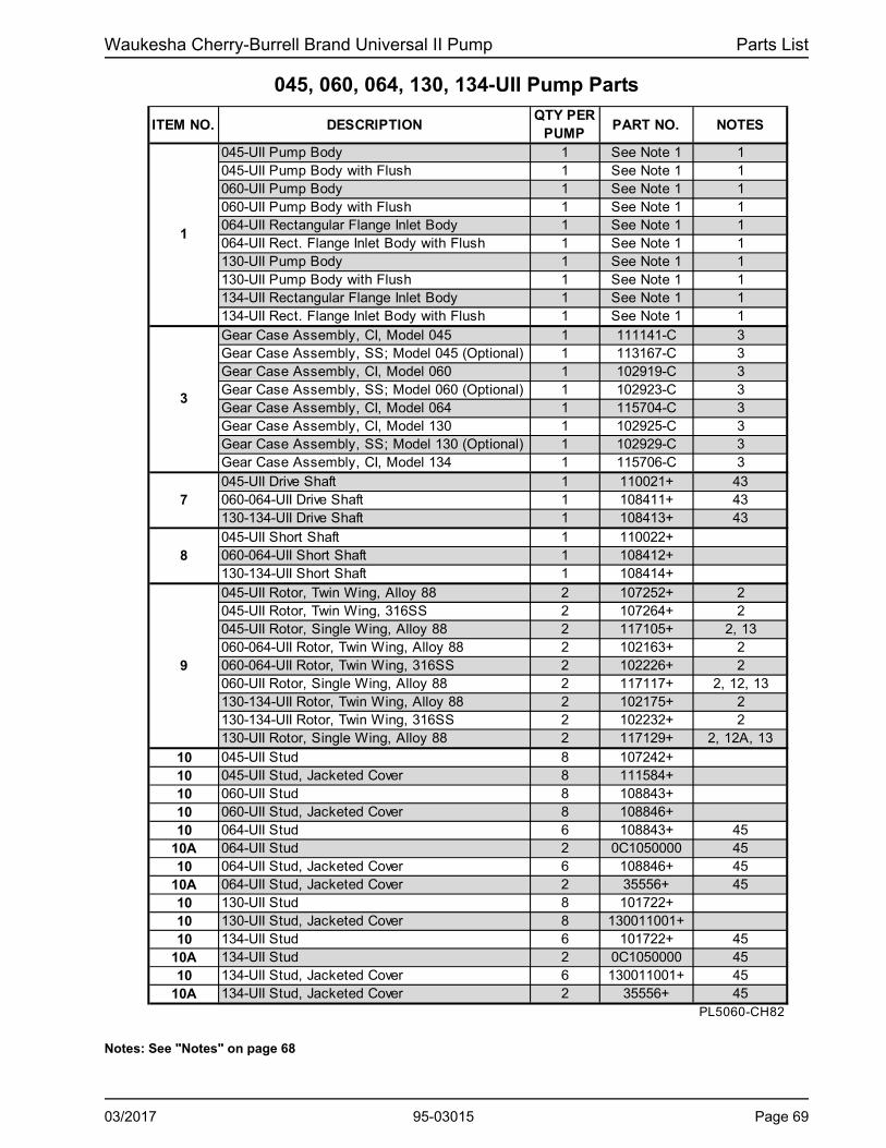
Waukesha Cherry-Burrell Brand Universal II Pump Parts List
045, 060, 064, 130, 134-UII Pump Parts
ITEM NO. DESCRIPTIONQTY PER
PUMPPART NO. NOTES
045-UII Pump Body 1 See Note 1 1045-UII Pump Body with Flush 1 See Note 1 1060-UII Pump Body 1 See Note 1 1060-UII Pump Body with Flush 1 See Note 1 1064-UII Rectangular Flange Inlet Body 1 See Note 1 1064-UII Rect. Flange Inlet Body with Flush 1 See Note 1 1130-UII Pump Body 1 See Note 1 1130-UII Pump Body with Flush 1 See Note 1 1134-UII Rectangular Flange Inlet Body 1 See Note 1 1134-UII Rect. Flange Inlet Body with Flush 1 See Note 1 1Gear Case Assembly, CI, Model 045 1 111141-C 3Gear Case Assembly, SS; Model 045 (Optional) 1 113167-C 3Gear Case Assembly, CI, Model 060 1 102919-C 3Gear Case Assembly, SS; Model 060 (Optional) 1 102923-C 3Gear Case Assembly, CI, Model 064 1 115704-C 3Gear Case Assembly, CI, Model 130 1 102925-C 3Gear Case Assembly, SS; Model 130 (Optional) 1 102929-C 3Gear Case Assembly, CI, Model 134 1 115706-C 3045-UII Drive Shaft 1 110021+ 43060-064-UII Drive Shaft 1 108411+ 43130-134-UII Drive Shaft 1 108413+ 43045-UII Short Shaft 1 110022+060-064-UII Short Shaft 1 108412+130-134-UII Short Shaft 1 108414+045-UII Rotor, Twin Wing, Alloy 88 2 107252+ 2045-UII Rotor, Twin Wing, 316SS 2 107264+ 2045-UII Rotor, Single Wing, Alloy 88 2 117105+ 2, 13060-064-UII Rotor, Twin Wing, Alloy 88 2 102163+ 2060-064-UII Rotor, Twin Wing, 316SS 2 102226+ 2060-UII Rotor, Single Wing, Alloy 88 2 117117+ 2, 12, 13130-134-UII Rotor, Twin Wing, Alloy 88 2 102175+ 2130-134-UII Rotor, Twin Wing, 316SS 2 102232+ 2130-UII Rotor, Single Wing, Alloy 88 2 117129+ 2, 12A, 13
10 045-UII Stud 8 107242+10 045-UII Stud, Jacketed Cover 8 111584+10 060-UII Stud 8 108843+10 060-UII Stud, Jacketed Cover 8 108846+10 064-UII Stud 6 108843+ 45
10A 064-UII Stud 2 0C1050000 4510 064-UII Stud, Jacketed Cover 6 108846+ 45
10A 064-UII Stud, Jacketed Cover 2 35556+ 4510 130-UII Stud 8 101722+10 130-UII Stud, Jacketed Cover 8 130011001+10 134-UII Stud 6 101722+ 45
10A 134-UII Stud 2 0C1050000 4510 134-UII Stud, Jacketed Cover 6 130011001+ 45
10A 134-UII Stud, Jacketed Cover 2 35556+ 45PL5060-CH82
3
1
7
8
9
Notes: See "Notes" on page 68
03/2017 95-03015 Page 69

Parts List Waukesha Cherry-Burrell Brand Universal II Pump
045, 060, 064, 130, 134-UII Common Parts
1
26
23
26C26B
2
9
37 2145
20
26A
36
26D
11
22
3
15
17
12
33A
33C
5 13
4139
24 48
10 34
30
42
4435 29
27
16
7
17 8
26E
32
25
PD100-347
25
33B
14
6
4365
66
47
46
Page 70 95-03015 03/2017

Waukesha Cherry-Burrell Brand Universal II Pump Parts List
045, 060, 064, 130, 134-UII Common PartsITEM NO.
DESCRIPTIONQTY. PER
PUMPPART NO. NOTES
Pump Cover 1 101848+Jacketed Cover 1 107668+Pump Cover Vented - Complete Assembly 1Gear Case Cover, Steel 1 070106000+Gear Case Cover, SS; Optional 1 102282+
5 Gear, Drive Shaft, Spur 1 107404+6 Gear, Short Shaft, Spur 1 107404+
Hex Nut 8 108371+Wing Nut, Optional 8 105852+
12 Oil Seal, Gear Case Cover 1 000030012+13 Oil Seal, Gear Case Rear 2 000030011+14 Grease Seal, Bearing Retainer 2 101829+ 315 Bearing, Rear 2 107186+16 Bearing, Front 2 060036000+17 Key, Gear 2 060037000+20 Dowel Pin, Upper Cover Side 1 124586+ 4321 Dowel Pin, Upper Gear Case Side 1 124584+ 4422 Dowel Pin, Lower Cover Side 1 137003+ 4323 Dowel Pin, Lower Gear Case Side 1 137002+ 44
Oil Plug, M20 x 1.5" 5 115798+ 40Oil Level Indicator, M20 x 1.5" 1 115799+ 40Oil Level Indicator, ATEX, M20 x 1.5 1 131417+
25 Silicone Sealant 1 000142301+26 Nut, Rotor 2 101806+
* O-Ring, Rotor Nut, Buna N 2 N70227* O-Ring, Rotor Nut, EPDM 2 E70227* O-Ring, Rotor Nut, FKM 2 V70227
26B Belleville Washer 2 101693+* O-Ring, Retainer, Buna N 2 N70119* O-Ring, Retainer, EPDM 2 E70119* O-Ring, Retainer, FKM 2 V70119* O-Ring, Rotor Hub, Buna N 2 N70224* O-Ring, Rotor Hub, EPDM 2 E70224* O-Ring, Rotor Hub, FKM 2 V70224
PL5060-CH83
24
2
4
26A
11
26D
26C
Notes:
* Recommended Spare Parts1. Please configure in E-Sales.3. For bearing isolator kit, see page 97.40. Applies to pumps shipped after October 2003. Pumps shipped prior to October 2003 used qty 6 of plug w/washer, part
number 000046004+.43. Exposed length of dowel pin: .444" (11.3 mm)44. Exposed length of dowel pin: .563" (14.3 mm)47. For Shaft & Bearing assembly part numbers, see page 96.
03/2017 95-03015 Page 71

Parts List Waukesha Cherry-Burrell Brand Universal II Pump
045, 060, 064, 130, 134-UII Common Parts, cont’d
1
9
10
29
46 26
23
26C
26B
2
2120
26A
26D22
3
15 11
12 5 13
24
256
4
3745
36
33A
33C
4139
48
34
4244
35
4365
66
177
817
PD100-347A
3027
26E
16
25
14
32
33B
47
31
36B
Notes:
5. 123531+ is available until stock is depleted, then will be replaced by 121828+. CTD = Coated Steel6. 101812+ is used with bearing isolators; for std. lip seal, use part # 121828+. SS = Stainless Steel7. For bearing isolator kit, and for pumps older than 7/12/04, see page 97.
ITEM NO.
DESCRIPTIONQTY. PER
PUMP
PART NO.
NOTES
045-UII Key, Rotor 2 110926+060-064-UII Key, Rotor 2 101823+130-134-UII Key, Rotor 2 101825+
27 Shim Kit 2 117891+29 Spacer, Gear to Rear Bearing 2 107187+30 Bearing Spacer 2 060055003+31 Grease Retainer, Rear Bearing 2 STD091002
Bearing Retainer, Front, CTD 2 123531+ 5, 7Bearing Retainer, Front SS, for std. lip seal 2 121828+ 6, 7Bearing Retainer, Front SS, used with bearing isolators. 2 101812+ 6, 7
PL5060-CH84
26E
32
Page 72 95-03015 03/2017

Waukesha Cherry-Burrell Brand Universal II Pump Parts List
045, 060, 064, 130, 134-UII Common Parts, cont’d
ITEM NO.
DESCRIPTIONQTY. PER
PUMP
PART NO.
NOTES
33A 3/8-16 x 3/4" HHCS, SS Gear Case Cover 6 30-5033B 3/8-16 x 1-1/4" HHCS, SS Bearing Retainer 8 30-6033C 3/8" Flat Washer, Gear Case Cover 6 43-3034 Dowel Bushing, Upper 1 CD011600035 Dowel Bushing, Lower 1 CD0116 100
O-Ring, Pump Cover, Buna N 1 N70373O-Ring, Pump Cover, EPDM 1 E70373O-Ring, Pump Cover, FKM 1 V70373O-Ring, Pump Cover, Silicone 1 S75373064-UII O-Ring, Rectangular Flange, Buna N 1 N70366064-UII O-Ring, Rectangular Flange, EPDM 1 E70366064-UII O-Ring, Rectangular Flange, FKM 1 V70366134-UII O-Ring, Rectangular Flange, Buna N 1 N70369134-UII O-Ring, Rectangular Flange, EPDM 1 E70369134-UII O-Ring, Rectangular Flange, FKM 1 V70369
37 Stop Pin, Seal 6 101720+39 Lockwasher, Gear 2 STD13600941 Locknut, Gear 2 STD236009
Gear Case Shim, CI 1 070110000+Gear Case Shim, SS; Optional 1 102286+Pump Pedestal, 5.5", Optional 1 CD0110SM5Pump Pedestal, 10", Optional 1 CD0110SM1
43 Plastic Cap Plug 6 000121001+44 1/2-13 x 1-1/4" SS SHCS 4 30-503
045-UII Body Retaining Screws, 5/16-8 x 2-1/2" 2 30-615060-064-UII Body Retaining Screws, 5/16-8 x 3" 2 30-319130-134-UII Body Retaining Screws, 5/16-8 x 4" 2 30-423
46 Eye Bolt, 1/2 -13 2 30-360Key, Coupling - 3/8 x 3/8 x 1-5/8" 1 000037003+Key, Coupling - Tru-Fit 1 119716+
48 Cleanout Plug 2 41013+ 1561 Name Plate, Sanitary 1 135624+62 #2 x .187” RHDS 4 30-35565 Caution Plate 2 121694+66 Warning Label 2 33-60
045-060-130-UII Grease Fitting, 1/8" (straight) 4 BD0092000064-134-UII Grease Fitting, 1/8" (angled) 4 BD0092 100
68 Plastic Cap, Grease Fitting 4 BD0093000PL5060-CH85
*
36B*
42
45
47
36
67
Notes:
* Recommended Spare Parts15. For an older gearcase without a threaded plug hole, use plug p/n 000121001+16. For seals, see page 89.17. For vented covers, see page 98.47. For Shaft & Bearing assembly part numbers, see page 96.
03/2017 95-03015 Page 73

Parts List Waukesha Cherry-Burrell Brand Universal II Pump
180, 184, 220, 224-UII Pump Parts
.
1
26
23
26C26B
2
9
37 21
4520
26A
36
26D
11
22
3
15
17
12
33A
33C
513
4139
2448
10 34
30
4244
35 29
27
16
7
17 8
26E
32
25
PD100-345
25
33B
14
6
434665
66
47
9
136B 10A
Page 74 95-03015 03/2017
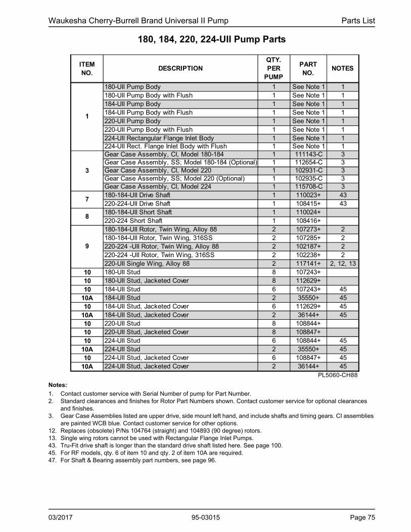
Waukesha Cherry-Burrell Brand Universal II Pump Parts List
180, 184, 220, 224-UII Pump Parts
ITEM NO.
DESCRIPTIONQTY. PER
PUMP
PART NO.
NOTES
180-UII Pump Body 1 See Note 1 1180-UII Pump Body with Flush 1 See Note 1 1184-UII Pump Body 1 See Note 1 1184-UII Pump Body with Flush 1 See Note 1 1220-UII Pump Body 1 See Note 1 1220-UII Pump Body with Flush 1 See Note 1 1224-UII Rectangular Flange Inlet Body 1 See Note 1 1224-UII Rect. Flange Inlet Body with Flush 1 See Note 1 1Gear Case Assembly, CI, Model 180-184 1 111143-C 3Gear Case Assembly, SS; Model 180-184 (Optional) 1 112654-C 3Gear Case Assembly, CI, Model 220 1 102931-C 3Gear Case Assembly, SS; Model 220 (Optional) 1 102935-C 3Gear Case Assembly, CI, Model 224 1 115708-C 3180-184-UII Drive Shaft 1 110023+ 43220-224-UII Drive Shaft 1 108415+ 43180-184-UII Short Shaft 1 110024+220-224 Short Shaft 1 108416+180-184-UII Rotor, Twin Wing, Alloy 88 2 107273+ 2180-184-UII Rotor, Twin Wing, 316SS 2 107285+ 2220-224 -UII Rotor, Twin Wing, Alloy 88 2 102187+ 2220-224 -UII Rotor, Twin Wing, 316SS 2 102238+ 2220-UII Single Wing, Alloy 88 2 117141+ 2, 12, 13
10 180-UII Stud 8 107243+10 180-UII Stud, Jacketed Cover 8 112629+10 184-UII Stud 6 107243+ 45
10A 184-UII Stud 2 35550+ 4510 184-UII Stud, Jacketed Cover 6 112629+ 45
10A 184-UII Stud, Jacketed Cover 2 36144+ 4510 220-UII Stud 8 108844+10 220-UII Stud, Jacketed Cover 8 108847+10 224-UII Stud 6 108844+ 45
10A 224-UII Stud 2 35550+ 4510 224-UII Stud, Jacketed Cover 6 108847+ 45
10A 224-UII Stud, Jacketed Cover 2 36144+ 45PL5060-CH88
7
1
8
9
3
Notes:
1. Contact customer service with Serial Number of pump for Part Number.2. Standard clearances and finishes for Rotor Part Numbers shown. Contact customer service for optional clearances
and finishes.3. Gear Case Assemblies listed are upper drive, side mount left hand, and include shafts and timing gears. CI assemblies
are painted WCB blue. Contact customer service for other options.12. Replaces (obsolete) P/Ns 104764 (straight) and 104893 (90 degree) rotors.13. Single wing rotors cannot be used with Rectangular Flange Inlet Pumps.43. Tru-Fit drive shaft is longer than the standard drive shaft listed here. See page 100.45. For RF models, qty. 6 of item 10 and qty. 2 of item 10A are required.47. For Shaft & Bearing assembly part numbers, see page 96.
03/2017 95-03015 Page 75

Parts List Waukesha Cherry-Burrell Brand Universal II Pump
180, 184, 220, 224-UII Common Parts
1
9
37
45
36
33A
33C
4139
48
10 3430
4244
35 29
27
7
17 8
26E
32
33B
4365
66
47
PD100-347
1
36B
26
23
26C26B
2
21 20
26A
26D
11
22
3
15
17
12 5 13
24
16
2525
14
6
46
4
Page 76 95-03015 03/2017
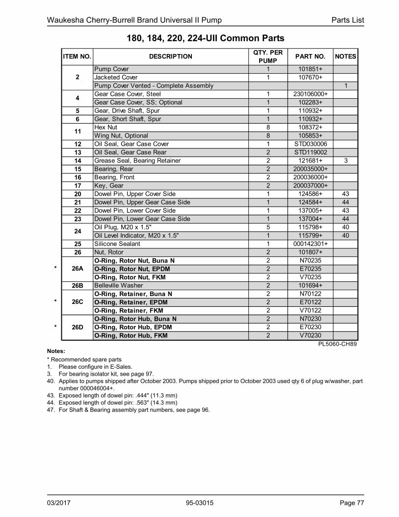
Waukesha Cherry-Burrell Brand Universal II Pump Parts List
180, 184, 220, 224-UII Common Parts
ITEM NO. DESCRIPTIONQTY. PER
PUMPPART NO. NOTES
Pump Cover 1 101851+Jacketed Cover 1 107670+Pump Cover Vented - Complete Assembly 1Gear Case Cover, Steel 1 230106000+Gear Case Cover, SS; Optional 1 102283+
5 Gear, Drive Shaft, Spur 1 110932+6 Gear, Short Shaft, Spur 1 110932+
Hex Nut 8 108372+Wing Nut, Optional 8 105853+
12 Oil Seal, Gear Case Cover 1 STD03000613 Oil Seal, Gear Case Rear 2 STD11900214 Grease Seal, Bearing Retainer 2 121681+ 315 Bearing, Rear 2 200035000+16 Bearing, Front 2 200036000+17 Key, Gear 2 200037000+20 Dowel Pin, Upper Cover Side 1 124586+ 4321 Dowel Pin, Upper Gear Case Side 1 124584+ 4422 Dowel Pin, Lower Cover Side 1 137005+ 4323 Dowel Pin, Lower Gear Case Side 1 137004+ 44
Oil Plug, M20 x 1.5" 5 115798+ 40Oil Level Indicator, M20 x 1.5" 1 115799+ 40
25 Silicone Sealant 1 000142301+26 Nut, Rotor 2 101807+
O-Ring, Rotor Nut, Buna N 2 N70235O-Ring, Rotor Nut, EPDM 2 E70235O-Ring, Rotor Nut, FKM 2 V70235
26B Belleville Washer 2 101694+O-Ring, Retainer, Buna N 2 N70122O-Ring, Retainer, EPDM 2 E70122O-Ring, Retainer, FKM 2 V70122O-Ring, Rotor Hub, Buna N 2 N70230O-Ring, Rotor Hub, EPDM 2 E70230O-Ring, Rotor Hub, FKM 2 V70230
PL5060-CH89
26D
11
26A
26C
2
4
24
*
*
*
Notes:
* Recommended spare parts1. Please configure in E-Sales.3. For bearing isolator kit, see page 97.40. Applies to pumps shipped after October 2003. Pumps shipped prior to October 2003 used qty 6 of plug w/washer, part
number 000046004+.43. Exposed length of dowel pin: .444" (11.3 mm)44. Exposed length of dowel pin: .563" (14.3 mm)47. For Shaft & Bearing assembly part numbers, see page 96.
03/2017 95-03015 Page 77

Parts List Waukesha Cherry-Burrell Brand Universal II Pump
180, 184, 220, 224-UII Common Parts, cont’d
1
9
10
29
46 26
23
26C
26B
2
2120
26A
26D22
3
15 11
12 5 13
24
256
4
3745
36
33A
33C
4139
48
34
4244
35
4365
66
177
817
PD100-347A
3027
26E
16
25
14
32
33B
47
31
36B
Notes: (See "Notes" column on page 79)
* Recommended Spare Parts1. For pumps purchased before about 1990, replace both spacers, as 40878+ will not work correctly with the old design
spacer (200055000).3. For pumps manufactured after July 2004. For bearing isolator kit, and for pumps prior to July 2004, see page 97.15. For an older gearcase without a threaded plug hole, use plug p/n 000121001+16. For seals, see page 89. For vented covers, see page 98.47. For Shaft & Bearing assembly part numbers, see page 96.
Page 78 95-03015 03/2017

Waukesha Cherry-Burrell Brand Universal II Pump Parts List
180, 184, 220, 224-UII Common Parts, cont’d
ITEM NO.
DESCRIPTIONQTY. PER
PUMPPART NO. NOTES
180-184-UII Key, Rotor 2 101828+220-224-UII Key, Rotor 2 101827+
27 Shim Kit 2 117892+29 Spacer, Gear to Rear Bearing 2 40878+ 130 Bearing Spacer 2 40752+
Bearing Retainer, Front, SS 2 121829+ 3Bearing Retainer, Front, SS, used with bearing isolators 2 101813+ 3
33A 3/8-16 x 3/4" HHCS, SS Gear Case Cover 8 30-5033B 3/8-16 x 1-1/4" HHCS, SS Bearing Retainer 8 30-6033C 3/8" Flat Washer, Gear Case Cover 8 43-3034 Dowel Bushing, Upper 1 CD011600035 Dowel Bushing, Lower 1 CD0116100
O-Ring, Pump Cover, Buna N 1 N70381O-Ring, Pump Cover, EPDM 1 E70381O-Ring, Pump Cover, FKM 1 V70381O-Ring, Pump Cover, Silicone 1 S75381184-UII O-ring, Rectangular Flange, Buna N 1 N70374184-UII O-ring, Rectangular Flange, EPDM 1 E70374184-UII O-ring, Rectangular Flange, FKM 1 V70374224-UII O-Ring, Rectangular Flange, Buna N 1 N70376224-UII O-Ring, Rectangular Flange, EPDM 1 E70376224-UII O-Ring, Rectangular Flange, FKM 1 V70376
37 Stop Pin, Seal 6 101720+39 Lockwasher, Gear 2 STD13601141 Locknut, Gear 2 STD236011
Gear Case Shim, CI 1 230110000+Gear Case Shim, SS; Optional 1 102287+Pump Pedestal, 9", Optional 1 GD0110SM9Pump Pedestal, 13", Optional 1 GD0110SM1
43 Plastic Cap Plug 6 000121001+44 1/2-13 x 2" SS SHCS 4 30-44
180-184-UII Body Retaining Screws, 3/8-16 x 4" 2 30-323220-224-UII Body Retaining Screws, 3/8-16 x 4-1/2" 2 30-499
46 Eye Bolt, 1/2 -13 2 30-360Key, Coupling - 1/2 x 1/2 x 1-7/8" 1 000037004+Key, Coupling - Tru-Fit 1 119717+
48 Cleanout Plug 2 41013+ 1561 Name Plate, Sanitary 1 001061015+62 #2 x .187” RHDS 4 30-35565 Caution Plate 2 121694+66 Warning Label 2 33-60
180-184-220-UII Grease Fitting, 1/8" (straight) 4 BD0092000224-UII Grease Fitting, 1/8" (angled) 4 BD0092100
68 Plastic Cap, Grease Fitting 4 BD0093000PL5060-CH90
26E
32
36
36B
42
45
*
*
47
67
Notes: See page 78.
03/2017 95-03015 Page 79

Parts List Waukesha Cherry-Burrell Brand Universal II Pump
210, 213, 214, 320, 323, 324, 370-UII Pump Parts
.
12
4
5 13
3
43 46 10
15
47
33A 33C
3027 17
726E
32 33B14
3130A
1641
24 48
42
44 3429
825
25
44A
56
6
PD100-354
28
2
20
9
37 21
4526C
26B
36
26D
11
36B
26
10A28A
28D
66
65
1910A
1
Notes (see "Notes" column on page 81):
1. Contact customer service with Serial Number of pump for Part Number.2. Standard clearances and finishes for Rotor Part Numbers shown. Contact customer service for optional clearances
and finishes.3. Gear Case Assemblies listed are upper drive, side mount left hand, and include shafts and timing gears. CI assemblies
are painted WCB blue. Contact customer service for other options.12. Replaces (obsolete) P/Ns 107662 (straight) and 107663 (90 degree) rotors. 43. Tru-Fit drive shaft is longer than the standard drive shaft listed here. See page 100.47. For Shaft & Bearing assembly part numbers, see page 96.
Page 80 95-03015 03/2017

Waukesha Cherry-Burrell Brand Universal II Pump Parts List
210, 213, 214, 320, 323, 324, 370-UII Pump Parts
ITEM NO. DESCRIPTIONQTY. PER
PUMPPART NO. NOTES
210-UII Pump Body 1 See Note 1 1210-UII Pump Body with Flush 1 See Note 1 1213-UII Pump Body 1 See Note 1 1214-UII Pump Body 1 See Note 1 1214-UII Pump Body with Flush 1 See Note 1 1320-UII Pump Body 1 See Note 1 1320-UII Pump Body with Flush 1 See Note 1 1323-UII Pump Body 1 See Note 1 1324-UII Pump Body 1 See Note 1 1324-UII Pump Body with Flush 1 See Note 1 1370-UII Pump Body 1 See Note 1 1370-UII Pump Body with Flush 1 See Note 1 1Gear Case Assembly, CI, Model 210-213 1 112709-C 3Gear Case Assembly, CI, Model 214 1 112709B-C 3Gear Case Assembly, CI, Model 320-323-370 1 105479-C 3Gear Case Assembly, CI, Model 324 1 105479B-C 3210-214-UII Drive Shaft 1 112186+ 43213-UII Drive Shaft 1 112188+ 43320-324-UII Drive Shaft 1 108417+ 43323-UII Drive Shaft 1 113960+ 43370-UII Drive Shaft 1 124839+ 43210-214-UII Short Shaft 1 112187+213-UII Short Shaft 1 112189+320-324-UII Short Shaft 1 108418+323-UII Short Shaft 1 113961+370-UII Short Shaft 1 124840+210-213-214-UII Rotor, Twin Wing, Alloy 88 2 112199+ 2210-213-214-UII Rotor, Twin Wing, 316SS 2 112211+ 2210-213-214-UII Rotor, Single Wing, Alloy 88 2 117220+ 2320-324-UII Rotor, Twin Wing, Alloy 88 2 105427+ 2320-324-UII Rotor, Twin Wing, 316SS 2 105439+ 2320-324-UII Rotor, Single Wing, Alloy 88 2 117153+ 2, 12323-UII Rotor, Twin Wing, Alloy 88 2 114022+ 2370-UII Rotor, Twin Wing, Alloy 88 2 124849+ 2370-UII Rotor, Twin Wing, 316SS 2 124861+ 2210-213-214-320-323-324-UII Stud, Long 4 112191+370-UII Stud, Long 4 124838+
2 111292+2 40699+
210-213-320-323-370-UII Stud, Short 4 111292+PL5060-CH93
214-324-UII Stud, Short10A
1
3
7
8
9
10
Notes: See page 80.
03/2017 95-03015 Page 81

Parts List Waukesha Cherry-Burrell Brand Universal II Pump
210, 213, 214, 320, 323, 324, 370-UII Common Parts
28
1
2
20
9
37 21
45 26C26B
36
26D
11
26A26
10A28A
3031
30A
28D
12
4
5 13
3
4346
10
1547
33A 33C
27 177
26E32 33B
14
1641
24 48
42
44 34
29
8
25
25
44A
56*
6
PD100-353
66
65
Page 82 95-03015 03/2017

Waukesha Cherry-Burrell Brand Universal II Pump Parts List
210, 213, 214, 320, 323, 324, 370--UII Common PartsITEM NO.
DESCRIPTIONQTY PER
PUMPPART NO.
NOTES
210-224-UII Pump Cover 1 112865+210-224-UII Jacketed Cover 1 116342+320-324-370-UII Pump Cover 1 109974+320-324-370-UII Jacketed Cover 1 114359+213-323-UII Pump Cover 1 114020+
4 Gear Case Cover, Steel 1 40669+5 Gear, Drive Shaft, Spur 1 102470+6 Gear, Short Shaft, Spur 1 102470+
Hex Nut 8 108373+Wing Nut, Optional 8 110858+
12 Oil Seal, Gear Case Cover 1 STD03000413 Oil Seal, Gear Case Rear 2 102475+ 314 Grease Seal, Bearing Retainer 2 121681+ 415 Bearing, Rear 2 0H103600016 Bearing, Front 2 0H103600317 Key, Gear 2 0H103700020 Dowel Pins, Cover Side 2 0H1040000 4321 Dowel Pins, Gear Case Side 2 105871+ 44
Oil Plug, M20 x 1.5" 5 115798+ 40Oil Level Indicator, M20 x 1.5" 1 115799+ 40Oil Level Indicator, ATEX, M20 x 1.5 1 131417+
25 Silicone Sealant 1 000142301+26 Nut, Rotor 2 105409+
O-Ring, Rotor Nut, Buna N 2 N70237O-Ring, Rotor Nut, EPDM 2 E70237O-Ring, Rotor Nut, FKM 2 V70237O-Ring, Rotor Nut, Silicone 2 S75237
26B Washer, Belleville 2 105411+O-Ring, Retainer, Buna N 2 N70125O-Ring, Retainer, EPDM 2 E70125O-Ring, Retainer, FKM 2 V70125O-Ring, Retainer, Silicone 2 S75125O-Ring, Rotor Hub, Buna N 2 N70232O-Ring, Rotor Hub, EPDM 2 E70232O-Ring, Rotor Hub, FKM 2 V70232O-Ring, Rotor Hub, Silicone 2 S75232210-213-224-UII Key, Rotor 2 105422+320-323-324-370-UII Key, Rotor 2 105421+
27 Shim Kit 2 117893+PL5060-CH94
*
*
*
26E
26A
26D
2
11
26C
24
Notes:
* Recommended Spare Parts3. Applies to pumps shipped after July 2001. Prior to this date, this part was not required. Check the pump serial number
to verify the date of manufacture and identify the part number required.4. For pumps manufactured after July 2004. For bearing isolator kit, and for pumps prior to July 2004, see page 97.40. Applies to pumps shipped after October 2003. Pumps shipped prior to October 2003 used qty 6 of plug with washer,
part number 000046004+.43. Exposed length of dowel pin: .75" (19 mm) 44. Exposed length of dowel pin: 1.125" (28.6 mm)47. For Shaft & Bearing assembly part numbers, see page 96.
03/2017 95-03015 Page 83
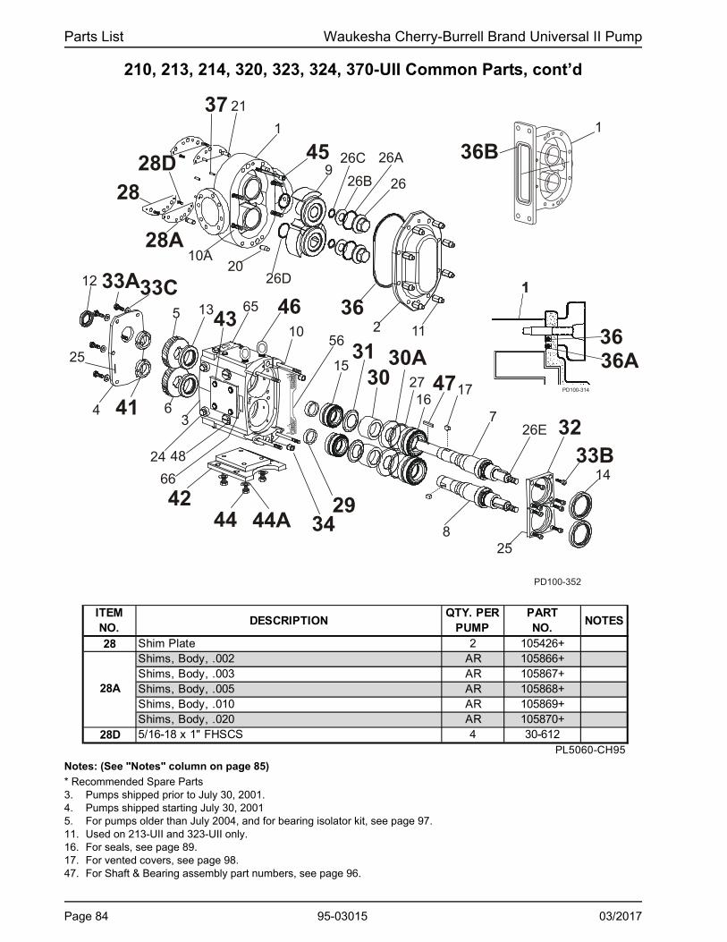
Parts List Waukesha Cherry-Burrell Brand Universal II Pump
210, 213, 214, 320, 323, 324, 370-UII Common Parts, cont’d
28
1
2
20
9
37 21
45 26C
26B
36
26D
11
26A
26
10A28A
28D
16
3233B
14
PD100-352
26E
12
4
5 13
3
4346 10
15
47
33A33C
30 27 17
7
31 30A
41
24 48
4244 34
29 8
25
25
44A
56
6
66
65
36
36B
36APD100-314
1
Notes: (See "Notes" column on page 85)
* Recommended Spare Parts3. Pumps shipped prior to July 30, 2001.4. Pumps shipped starting July 30, 20015. For pumps older than July 2004, and for bearing isolator kit, see page 97.11. Used on 213-UII and 323-UII only.16. For seals, see page 89.17. For vented covers, see page 98.47. For Shaft & Bearing assembly part numbers, see page 96.
ITEM NO.
DESCRIPTIONQTY. PER
PUMPPART NO.
NOTES
28 Shim Plate 2 105426+Shims, Body, .002 AR 105866+Shims, Body, .003 AR 105867+Shims, Body, .005 AR 105868+Shims, Body, .010 AR 105869+Shims, Body, .020 AR 105870+
28D 5/16-18 x 1" FHSCS 4 30-612PL5060-CH95
28A
Page 84 95-03015 03/2017

Waukesha Cherry-Burrell Brand Universal II Pump Parts List
210, 213, 214, 320, 323, 324, 370-UII Common Parts, cont’dITEM NO.
DESCRIPTIONQTY. PER
PUMPPART NO.
NOTES
Spacer, Gear to Rear Bearing 102474+ 4Spacer, Gear to Rear Bearing 117691+ 3
30 Bearing Spacer 2 102472+30A Spacer Seal 2 102473+31 Retainer, Grease 2 STD091000
Bearing Retainer, Front 123533+ 5Bearing Retainer, Front, SS, used with bearing isolators 121141+ 5
33A 3/8-16 x .75" HHCS 6 30-5033B 5/16-18 x 1" HHCS 8 30-3433C 3/8" Flat Washer 6 43-3034 Dowel Bushings 2 0H1116000
210-224-UII O-Ring, Pump Cover, Buna N 1 N70382210-224-UII O-Ring, Pump Cover, EPDM 1 E70382210-224-UII O-Ring, Pump Cover, FKM 1 V70382210-224-UII O-Ring, Pump Cover, Silicone 1 S75382320-324-370-UII O-Ring, Pump Cover, Buna N 1 N70383320-324-370-UII O-Ring, Pump Cover, EPDM 1 E70383320-324-370-UII O-Ring, Pump Cover, FKM 1 V70383320-324-370-UII O-Ring, Pump Cover, Silicone 1 S75383213-323-UII O-Ring, Pump Cover, Outer, EPDM 1 323117012+ 11213-323-UII O-Ring, Pump Cover, Outer, Silicone 1 323117013+ 11213-323-UII O-Ring, Pump Cover, Outer, FKM 1 323117014+ 11213-323-UII O-Ring, Pump Cover, Inner, EPDM 1 323117002+ 11213-323-UII O-Ring, Pump Cover, Inner, Silicone 1 323117003+ 11213-323-UII O-Ring, Pump Cover, Inner, FKM 1 323117004+ 11214-UII Flange O-ring, Buna N 1 N70377214-UII Flange O-ring, EPDM 1 E70377214-UII Flange O-ring, FKM 1 V70377324-UII Flange O-ring, Buna N 1 N70378324-UII Flange O-ring, EPDM 1 E70378324-UII Flange O-ring, FKM 1 V70378
37 Stop Pin, Seal 6 102438+41 Locknut, Gear 2 105697+
Gear Case Shim, CI 1 40288+Pump Pedestal, 22", Optional 1 324110226+
43 Plastic Cap Plug 8 000121001+44 1/2-13 x 1-3/4" HHCS 4 30-127X
44A Lock Washer, 1/2" 4 43-16210-213-214-UII Body Retaining Screws - 3/8-16 x 3-1/2" 2 30-326320-323-324-UII Body Retaining Screws - 3/8-16 x 4-1/2" 2 30-323370-UII Body Retaining Screws - 3/8-16 x 6" 2 30-717
46 Eye Bolt 3 30-360Key, Coupling - 5/8 x 5/8 x 2-3/4" 1 000037005+Key, Coupling - Tru-Fit 1 119718+
PL5060-CH95a
32
*
*
*
2
229
47
45
42
36
36A
36B
Notes: See page 84.
03/2017 95-03015 Page 85

Parts List Waukesha Cherry-Burrell Brand Universal II Pump
210, 213, 214, 320, 323, 324, 370-UII Common Parts, cont’d
Page 86 95-03015 03/2017

Waukesha Cherry-Burrell Brand Universal II Pump Parts List
210, 213, 214, 320, 323, 324, 370-UII Common Parts, cont’d
ITEM NO. DESCRIPTIONQTY. (per
pump)PART NO. NOTES
48 Cleanout Plug 2 41013+ 15210-213-UII Seal Guard 2 113503+
1 113503+1 126361+
320-323-370-UII Seal Guard 2 113504+1 113504+1 126360+
56A 1/4 - 20 x 3/8" HHCS 4 30-6860A 1/8-27 Aseptic Connection Pipe Plugs 10 STD128500 1161 Name Plate, Sanitary 1 135624+62 #2 x .187” RHDS 4 30-35565 Caution Plate 2 121694+66 Warning Label 2 33-6067 Grease Fitting, 1/8" 4 BD0092000 168 Plastic Cap, Grease Fitting 4 BD0093000
Notes: PL5060-CH96* Recommended Spare Parts1.
11.
15. For an older gearcase without a threaded plug hole, use plug p/n 000121001+
56
324-UII Seal Guard
214-UII Seal Guard
This grease fitting is the straight style. Part number BD0092100 is the angled style.
Used on 213-UII and 323-UII only.
Aseptic Flange
213-UII 323-UII
O-Ring, Port, Inner, EPDM 2 E70245 E70261 11O-Ring, Port, Inner, FKM 2 V70245 V70261 11O-Ring, Port, Inner, Silicone 2 S75245 S75261 11O-Ring, Port, Outer, EPDM 2 E70251 E70265 11O-Ring, Port, Outer, FKM 2 V70251 V70265 11O-Ring, Port, Outer, Silicone 2 S75251 S752565 11
Notes: PL5060-CH96a
11.
*
*
Used on 213-UII and 323-UII only.
NOTES
57
58
PART NO.QTY.(per
pump)DESCRIPTIONITEM NO.
03/2017 95-03015 Page 87

Parts List Waukesha Cherry-Burrell Brand Universal II Pump
Universal II Standard Seals
Standard Single Mechanical Seal
Aseptic Design Double Mechanical Seal (213, 323 UII ONLY)
Standard Double Mechanical Seal
Page 88 95-03015 03/2017
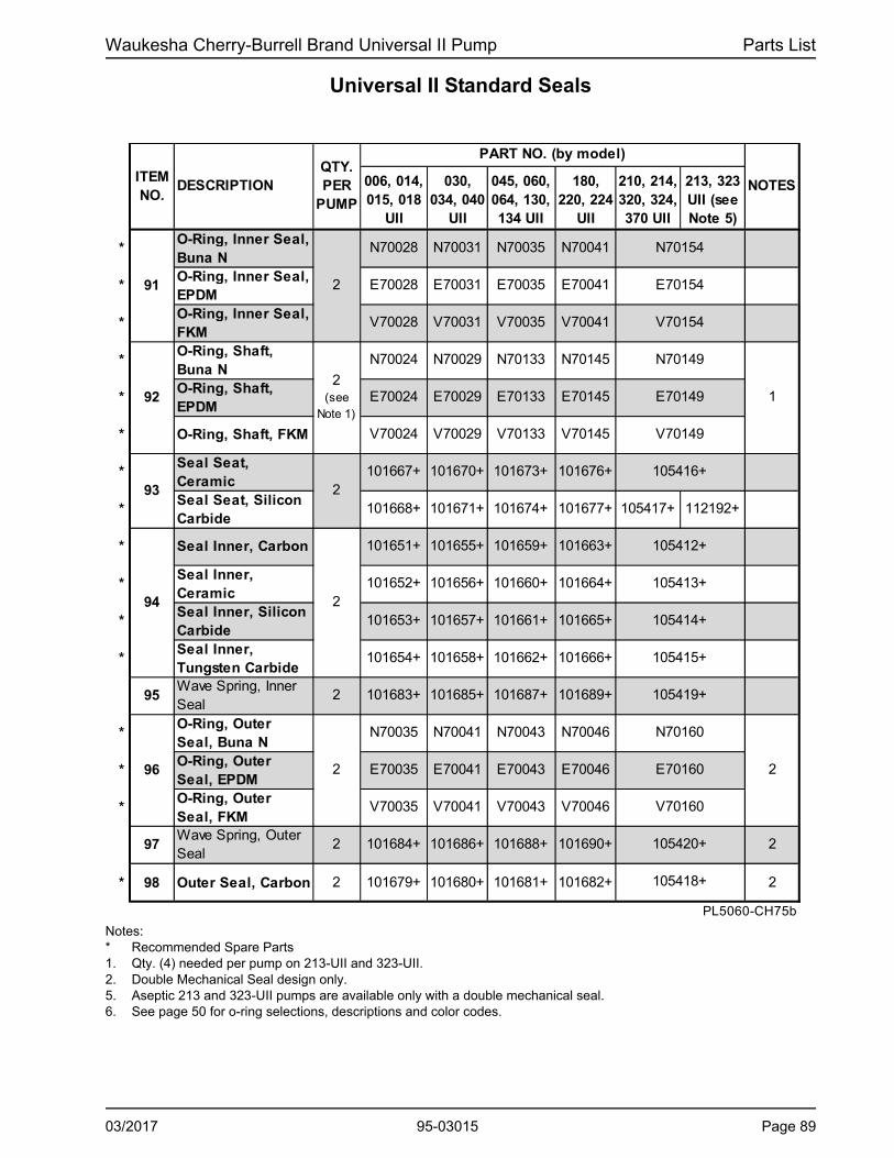
Waukesha Cherry-Burrell Brand Universal II Pump Parts List
Universal II Standard Seals
006, 014, 015, 018
UII
030, 034, 040
UII
045, 060, 064, 130, 134 UII
180, 220, 224
UII
210, 214, 320, 324, 370 UII
213, 323 UII (see Note 5)
*O-Ring, Inner Seal, Buna N
N70028 N70031 N70035 N70041
*O-Ring, Inner Seal, EPDM
E70028 E70031 E70035 E70041
*O-Ring, Inner Seal, FKM
V70028 V70031 V70035 V70041
*O-Ring, Shaft, Buna N
N70024 N70029 N70133 N70145
*O-Ring, Shaft, EPDM
E70024 E70029 E70133 E70145
* O-Ring, Shaft, FKM V70024 V70029 V70133 V70145
*Seal Seat, Ceramic
101667+ 101670+ 101673+ 101676+
*Seal Seat, Silicon Carbide
101668+ 101671+ 101674+ 101677+ 105417+ 112192+
* Seal Inner, Carbon 101651+ 101655+ 101659+ 101663+
*Seal Inner, Ceramic
101652+ 101656+ 101660+ 101664+
*Seal Inner, Silicon Carbide
101653+ 101657+ 101661+ 101665+
*Seal Inner, Tungsten Carbide
101654+ 101658+ 101662+ 101666+
95Wave Spring, Inner Seal
2 101683+ 101685+ 101687+ 101689+
*O-Ring, Outer Seal, Buna N
N70035 N70041 N70043 N70046
*O-Ring, Outer Seal, EPDM
E70035 E70041 E70043 E70046
*O-Ring, Outer Seal, FKM
V70035 V70041 V70043 V70046
97Wave Spring, Outer Seal
2 101684+ 101686+ 101688+ 101690+ 2
* 98 Outer Seal, Carbon 2 101679+ 101680+ 101681+ 101682+ 2
PL5060-CH75b
1
2
105419+
N70160
E70160
V70160
ITEM NO.
DESCRIPTIONQTY. PER
PUMP
96
91
92
93 2
2
2
94
NOTES
N70154
E70154
V70154
N70149
E70149
V70149
2
2 (see
Note 1)
105420+
105418+
PART NO. (by model)
105416+
105412+
105413+
105414+
105415+
Notes:* Recommended Spare Parts1. Qty. (4) needed per pump on 213-UII and 323-UII.2. Double Mechanical Seal design only.5. Aseptic 213 and 323-UII pumps are available only with a double mechanical seal. 6. See page 50 for o-ring selections, descriptions and color codes.
03/2017 95-03015 Page 89

Parts List Waukesha Cherry-Burrell Brand Universal II Pump
Universal II Specialty Seals
Universal II Narrow Face (NF) Seals
The Universal II Narrow Face (NF) Seal is available in the Single Mechanical Seal Design only. The smaller diameter rotating seal seat (item 93) is only used with the NF Seal.
(Standard Single Mechanical Seal shown for reference)
Universal II High-Pressure Barrier (HPB) Seals
The Universal II High Pressure Barrier (HPB) Seal is available in the Double Mechanical Seal Design only.
The maximum barrier pressure is 100 psi.
Recommended seal flush flow is 1/8 gpm.
To calculate the barrier pressure to ensure that the barrier fluid is on the seal instead of the product:
(( Dp - Sp) X 30% ) + Sp + 30 psi = Bp
Dp = pump discharge pressure Sp = pump suction pressure Bp = flush water pressure
(Standard Double Mechanical Seal shown for reference)
Standard Single Mechanical Seal
Standard Double Mechanical Seal
Page 90 95-03015 03/2017

Waukesha Cherry-Burrell Brand Universal II Pump Parts List
Universal II Specialty Seals
006, 014, 015, 018
UII
030, 034, 040
UII
045, 060, 064, 130, 134 UII
180, 220, 224 UII
210, 214, 320, 324. 370 UII
* O-Ring, Inner Seal, Buna N N70028 N70031 N70035 N70041 N70154* O-Ring, Inner Seal, EPDM E70028 E70031 E70035 E70041 E70154* O-Ring, Inner Seal, FKM V70028 V70031 V70035 V70041 V70154* O-Ring, Shaft, Buna N N70024 N70029 N70133 N70145 N70149* O-Ring, Shaft, EPDM E70024 E70029 E70133 E70145 E70149* O-Ring, Shaft, FKM V70024 V70029 V70133 V70145 V70149
*NF Seal Seat, Silicon Carbide
124743+ 124745+ 124747+ 124749+ 124751+
*NF Seal Seat, Tungsten Carbide
124744+ 124746+ 124748+ 124750+ 124752+
* HPB Seal Seat, Ceramic 101667+ 101670+ 101673+ 101676+ 105416+
*HPB Seal Seat, Silicon Carbide
101668+ 101671+ 101674+ 101677+ 105417+
*NF Seal, Inner, Silicon Carbide
124734+ 124736+ 124738+ 124740+ 124742+
*NF Seal, Inner, Tungsten Carbide
124733+ 124735+ 124737+ 124739+ 124741+
*HPB Seal, Inner, Silicon Carbide
110821+ 110823+ 110825+ 110827+ 110829+
*HPB Seal, Inner, Tungsten Carbide
122324+ 122325+ 122326+ 122327+ 122328+
95 Wave Spring, Inner Seal 2 101683+ 101685+ 101687+ 101689+ 105419+
* O-Ring, Outer Seal, Buna N N70035 N70041 N70043 N70046 N70160* O-Ring, Outer Seal, EPDM E70035 E70041 E70043 E70046 E70160* O-Ring, Outer Seal, FKM V70035 V70041 V70043 V70046 V70160
97 Wave Spring, Outer Seal 2 101684+ 101686+ 101688+ 101690+ 105420+ 2
* 98 Outer Seal, Carbon 2 101679+ 101680+ 101681+ 101682+ 105418+ 2
PL5060-CH75a
2 296
PART NO. (by model)
93
91
92
3, 4
2, 4
2
3, 4
2, 4
94
2
2
NOTESITEM NO.
DESCRIPTIONQTY. PER
PUMP
2
Notes:* Recommended Spare Parts2. Double Mechanical Seal design only.3. Single Mechanical Seal design only.4. HPB and NF seals are NOT available on the 213-UII or 323-UII.6. See page 50 for o-ring selections, descriptions and color codes.
03/2017 95-03015 Page 91

Parts List Waukesha Cherry-Burrell Brand Universal II Pump
Seal Kits - 006, 015, 018-UII, 014-UII, 030, 040-UII, 034-UIII
UII Model Description Kit Part# UII Model Description Kit Part#
SEAL KIT SM C/CE B 131420+ SEAL KIT SM C/CE B 129648+SEAL KIT SM C/SC B 133247+ SEAL KIT SM C/SC B 134300+SEAL KIT SM SC/SC B 133357+ SEAL KIT SM SC/SC B 133362+SEAL KIT SM TC/SC B 133496+ SEAL KIT SM TC/SC B 133501+SEAL KIT SM TC/SC 133497+ SEAL KIT SM C/CE E 133168+SEAL KIT SM C/CE E 133164+ SEAL KIT SM C/SC E 134302+SEAL KIT SM C/SC E 133249+ SEAL KIT SM SC/SC E 133363+SEAL KIT SM SC/SC 133358+ SEAL KIT SM TC/SC E 133503+SEAL KIT SM C/CE V 133163+ SEAL KIT SM C/CE V 123985+SEAL KIT SM C/SC V 133248+ SEAL KIT SM C/SC V 134301+SEAL KIT SM SC/SC V 126889+ SEAL KIT SM SC/SC V 125019+SEAL KIT SM TC/SC V 125945+ SEAL KIT SM TC/SC V 133502+SEAL KIT SM TCNF/SC V 137232+ SEAL KIT DM SC/SC-C/SC B 133905+SEAL KIT DM C/CE/C B 133820+ SEAL KIT DM SCNF/SC-C/SC B 133962+SEAL KIT DM SC/SC-C/SC B 133900+ SEAL KIT DM TCNF/SC-C/SC B 134025+SEAL KIT DM SCNF/SC-C/SC B 133956+ SEAL KIT DM C/CE-C/CE B 133825+SEAL KIT DM SCNFC-C/SC B 122956+ SEAL KIT DM SC/SC-C/SC E 133906+SEAL KIT DM TCNF/SC-C/SC B 134019+ SEAL KIT DM SCNF/SC-C/SC E 133964+SEAL KIT DM C/CE-C/CE E 133821+ SEAL KIT DM TCNF/SC-C/SC E 134027+SEAL KIT DM SC/SC-C/SC E 133901+ SEAL KIT DM C/CE-C/CE E 133826+SEAL KIT DM SCNF/SC-C/SC E 133958+ SEAL KIT DM C/CE-C/CE V 123986+SEAL KIT DM TCNF/SC-C/SC E 134021+ SEAL KIT DM SCNF/SC-C/SC V 133963+SEAL KIT DM SCNF/SC-C/SC V 133957+ SEAL KIT DM TCNF/SC-C/SC V 134026+SEAL KIT DM TCNF/SC-C/SC V 134020+ SEAL KIT DM SC/SC-C/SC V 130841+SEAL KIT DM C/CE V 130840+ SEAL KIT DM TC/SC-C/SC V 137907+SEAL KIT DM SC/SC-C/SC V 130847+ SEAL KIT SM C/CE B 133169+SEAL KIT DM TC/SC-C/SC V 137908+ SEAL KIT SM C/SC B 134303+SEAL KIT SM C/CE B 133165+ SEAL KIT SM SC/SC B 134294+SEAL KIT SM C/SC B 133250+ SEAL KIT SM TC/SC B 133504+SEAL KIT SM C/SC B 134297+ SEAL KIT SM C/CE V 133170+SEAL KIT SM SC/SC B 133359+ SEAL KIT SM C/SC V 134304+SEAL KIT SM TC/SC B 133498+ SEAL KIT SM SC/SC V 134295+SEAL KIT SM C/CE V 133166+ SEAL KIT SM TC/SC V 133505+SEAL KIT SM C/SC V 133255+ SEAL KIT DM C/CE/C B 133827+SEAL KIT SM C/SC V 134298+ SEAL KIT DM SC/SC-C/SC B 133907+SEAL KIT SM SC/SC V 133360+ SEAL KIT DM SCNF/SC-C/SC B 133965+SEAL KIT SM TC/SC V 133499+ SEAL KIT DM TCNF/SC-C/SC B 134028+SEAL KIT DM C/CE/C B 133822+ SEAL KIT DM C/CE/C E 133829+SEAL KIT DM SC/SC-C/SC B 133902+ SEAL KIT DM SC/SC-C/SC E 133909+SEAL KIT DM SCNF/SC-C/SC B 133959+ SEAL KIT DM SCNF/SC-C/SC 133967+SEAL KIT DM TCNF/SC-C/SC B 134022+ SEAL KIT DM TCNF/SC-C/SC 134030+SEAL KIT DM C/CE/C E 133824+ SEAL KIT DM C/CE/C V 133828+SEAL KIT DM SC/SC-C/SC E 133904+ SEAL KIT DM SC/SC-C/SC V 133908+SEAL KIT DM SCNF/SC-C/SC E 133961+ SEAL KIT DM SCNF/SC-C/SC V 133966+SEAL KIT DM TCNF/SC-C/SC E 134024+ SEAL KIT DM TCNF/SC-C/SC V 134029+SEAL KIT DM C/CE/C V 133823+ SEAL KIT SM C/CE 133171+SEAL KIT DM SC/SC-C/SC V 133903+ SEAL KIT SM C/SC E 134305+SEAL KIT DM SCNF/SC-C/SC V 133960+ SEAL KIT SM SC/SC E 134296+SEAL KIT DM TCNF/SC-C/SC V 134023+ SEAL KIT SM TC/SC E 133506+SEAL KIT SM C/CE 133167+SEAL KIT SM C/SC E 133256+SEAL KIT SM SC/SC E 133361+SEAL KIT SM TC/SC E 133500+
PL5060-CH131
006, 015, 018-UII
014-UII
030, 040-UII
034-UII
Key SM Single Mechanical DM Double Mechanical C Carbon CE Ceramic SC Silicon Carbide
TC Tungsten Carbide NF Narrow Face B BUNA E EPDM V FKM
Page 92 95-03015 03/2017

Waukesha Cherry-Burrell Brand Universal II Pump Parts List
Seal Kits - 045, 060, 130-UII, 180, 220-UIII
UII Model Description Kit Part# UII Model Description Kit Part#
SEAL KIT SM C/CE B 131422+ SEAL KIT SM C/CE B 133179+SEAL KIT SM C/SC B 133257+ SEAL KIT SM C/SC B 134309+SEAL KIT SM SC/SC B 133364+ SEAL KIT SM SC/SC B 134105+SEAL KIT SM TC/SC B 133507+ SEAL KIT SM TC/SC B 133518+SEAL KIT SM C/CE E 133172+ SEAL KIT SM C/CE V 133180+SEAL KIT SM C/CE E 133178+ SEAL KIT SM C/SC V 134310+SEAL KIT SM C/SC E 133258+ SEAL KIT SM SC/SC V 134106+SEAL KIT SM SC/SC E 133365+ SEAL KIT SM TC/SC V 133519+SEAL KIT SM TC/SC E 133508+ SEAL KIT DM C/CE/C B 133839+SEAL KIT SM C/CE V 126890+ SEAL KIT DM SC/SC-C/SC B 133922+SEAL KIT SM C/SC V 128193+ SEAL KIT DM SCNF/SC-C/SC B 133980+SEAL KIT SM SC/SC V 125020+ SEAL KIT DM TCNF/SC-C/SC B 134043+SEAL KIT SM TC/SC V 125023+ SEAL KIT DM C/CE/C E 133841+SEAL KIT DM C/CE-C/CE B 133830+ SEAL KIT DM SC/SC-C/SC E 133924+SEAL KIT DM SC/SC-C/SC B 133910+ SEAL KIT DM SCNF/SC-C/SC E 133982+SEAL KIT DM SCNF/SC-C/SC B 133968+ SEAL KIT DM TCNF/SC-C/SC E 134045+SEAL KIT DM TCNF/SC-C/SC B 134031+ SEAL KIT DM C/CE/C V 133840+SEAL KIT DM C/CE-C/CE E 133832+ SEAL KIT DM SC/SC-C/SC V 133923+SEAL KIT DM SC/SC-C/SC E 133912+ SEAL KIT DM SCNF/SC-C/SC V 133981+SEAL KIT DM SCNF/SC-C/SC E 133970+ SEAL KIT DM TCNF/SC-C/SC V 134044+SEAL KIT DM TCNF/SC-C/SC E 134033+ SEAL KIT SM C/CE E 133181+SEAL KIT DM C/CE-C/CE V 133831+ SEAL KIT SM C/SC E 134311+SEAL KIT DM SC/SC-C/SC V 128040+ SEAL KIT SM SC/SC E 134107+SEAL KIT DM SCNF/SC-C/SC V 133969+ SEAL KIT SM TC/SC E 133520+SEAL KIT DM TC/SC-C/SC V 136951+ SEAL KIT SM C/CE B 131423+SEAL KIT DM TCNF/SC-C/SC V 134032+ SEAL KIT SM C/SC B 134318+SEAL KIT DM TCNF/TC-C/TC V 135752+ SEAL KIT SM TC/SC B 133530+SEAL KIT SM C/CE B 133173+ SEAL KIT SM C/CE V 133196+SEAL KIT SM C/SC B 134306+ SEAL KIT SM C/SC V 134319+SEAL KIT SM SC/SC B 134099+ SEAL KIT SM SC/SC V 125021+SEAL KIT SM TC/SC B 133512+ SEAL KIT SM TC/SC V 125024+SEAL KIT SM C/CE V 133174+ SEAL KIT SM TC/TC V 136745+SEAL KIT SM C/SC V 134307+ SEAL KIT SM SC/SC B 133368+SEAL KIT SM SC/SC V 134100+ SEAL KIT DM C/CE-C/CE B 133848+SEAL KIT SM TC/SC V 133513+ SEAL KIT DM SC/SC-C/SC B 133928+SEAL KIT DM C/CE/C B 133836+ SEAL KIT DM SCNF/SC-C/SC B 133989+SEAL KIT DM SC/SC-C/SC B 133916+ SEAL KIT DM TCNF/SC-C/SC B 134049+SEAL KIT DM SCNF/SC-C/SC B 133974+ SEAL KIT DM C/CE-C/CE E 133850+SEAL KIT DM TCNF/SC-C/SC B 134037+ SEAL KIT DM SC/SC-C/SC E 133929+SEAL KIT DM C/CE/C E 133838+ SEAL KIT DM SCNF/SC-C/SC E 133991+SEAL KIT DM SC/SC-C/SC E 133918+ SEAL KIT DM TCNF/SC-C/SC E 134071+SEAL KIT DM SCNF/SC-C/SC E 133976+ SEAL KIT DM C/CE-C/CE V 133849+SEAL KIT DM TCNF/SC-C/SC E 134039+ SEAL KIT DM SC/SC-C/SC V 129647+SEAL KIT DM C/CE/C V 133837+ SEAL KIT DM SCNF/SC-C/SC V 133990+SEAL KIT DM SC/SC-C/SC V 133917+ SEAL KIT DM TCNF/SC-C/SC V 134050+SEAL KIT DM SCNF/SC-C/SC V 133975+ SEAL KIT SM C/CE E 133197+SEAL KIT DM TCNF/SC-C/SC V 134038+ SEAL KIT SM C/SC E 134320+SEAL KIT SM C/CE E 133175+ SEAL KIT SM TC/SC E 133531+SEAL KIT SM C/SC E 134308+ SEAL KIT SM SC/SC E 133369+SEAL KIT SM SC/SC E 134101+SEAL KIT SM TC/SC E 133514+
PL5060-CH132
045, 060, 130-UII
180, 220-UII
064-UII
134-UII
Key SM Single Mechanical DM Double Mechanical C Carbon CE Ceramic SC Silicon Carbide
TC Tungsten Carbide NF Narrow Face B BUNA E EPDM V FKM
03/2017 95-03015 Page 93
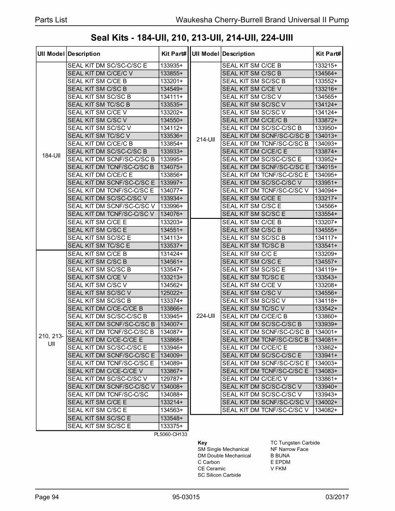
Parts List Waukesha Cherry-Burrell Brand Universal II Pump
Seal Kits - 184-UII, 210, 213-UII, 214-UII, 224-UIII
UII Model Description Kit Part# UII Model Description Kit Part#
SEAL KIT DM SC/SC-C/SC E 133935+ SEAL KIT SM C/CE B 133215+SEAL KIT DM C/CE/C V 133855+ SEAL KIT SM C/SC B 134564+SEAL KIT SM C/CE B 133201+ SEAL KIT SM SC/SC B 133552+SEAL KIT SM C/SC B 134549+ SEAL KIT SM C/CE V 133216+SEAL KIT SM SC/SC B 134111+ SEAL KIT SM C/SC V 134565+SEAL KIT SM TC/SC B 133535+ SEAL KIT SM SC/SC V 134124+SEAL KIT SM C/CE V 133202+ SEAL KIT SM SC/SC V 134124+SEAL KIT SM C/SC V 134550+ SEAL KIT DM C/CE/C B 133872+SEAL KIT SM SC/SC V 134112+ SEAL KIT DM SC/SC-C/SC B 133950+SEAL KIT SM TC/SC V 133536+ SEAL KIT DM SCNF/SC-C/SC B 134013+SEAL KIT DM C/CE/C B 133854+ SEAL KIT DM TCNF/SC-C/SC B 134093+SEAL KIT DM SC/SC-C/SC B 133933+ SEAL KIT DM C/CE/C E 133874+SEAL KIT DM SCNF/SC-C/SC B 133995+ SEAL KIT DM SC/SC-C/SC E 133952+SEAL KIT DM TCNF/SC-C/SC B 134075+ SEAL KIT DM SCNF/SC-C/SC E 134015+SEAL KIT DM C/CE/C E 133856+ SEAL KIT DM TCNF/SC-C/SC E 134095+SEAL KIT DM SCNF/SC-C/SC E 133997+ SEAL KIT DM SC/SC-C/SC V 133951+SEAL KIT DM TCNF/SC-C/SC E 134077+ SEAL KIT DM TCNF/SC-C/SC V 134094+SEAL KIT DM SC/SC-C/SC V 133934+ SEAL KIT SM C/CE E 133217+SEAL KIT DM SCNF/SC-C/SC V 133996+ SEAL KIT SM C/SC E 134566+SEAL KIT DM TCNF/SC-C/SC V 134076+ SEAL KIT SM SC/SC E 133554+SEAL KIT SM C/CE E 133203+ SEAL KIT SM C/CE B 133207+SEAL KIT SM C/SC E 134551+ SEAL KIT SM C/SC B 134555+SEAL KIT SM SC/SC E 134113+ SEAL KIT SM SC/SC B 134117+SEAL KIT SM TC/SC E 133537+ SEAL KIT SM TC/SC B 133541+SEAL KIT SM C/CE B 131424+ SEAL KIT SM C/C E 133209+SEAL KIT SM C/SC B 134561+ SEAL KIT SM C/SC E 134557+SEAL KIT SM SC/SC B 133547+ SEAL KIT SM SC/SC E 134119+SEAL KIT SM C/CE V 133213+ SEAL KIT SM TC/SC E 133543+SEAL KIT SM C/SC V 134562+ SEAL KIT SM C/CE V 133208+SEAL KIT SM SC/SC V 125022+ SEAL KIT SM C/SC V 134556+SEAL KIT SM SC/SC B 133374+ SEAL KIT SM SC/SC V 134118+SEAL KIT DM C/CE-C/CE B 133866+ SEAL KIT SM TC/SC V 133542+SEAL KIT DM SC/SC-C/SC B 133945+ SEAL KIT DM C/CE/C B 133860+SEAL KIT DM SCNF/SC-C/SC B 134007+ SEAL KIT DM SC/SC-C/SC B 133939+SEAL KIT DM TCNF/SC-C/SC B 134087+ SEAL KIT DM SCNF/SC-C/SC B 134001+SEAL KIT DM C/CE-C/CE E 133868+ SEAL KIT DM TCNF/SC-C/SC B 134081+SEAL KIT DM SC/SC-C/SC E 133946+ SEAL KIT DM C/CE/C E 133862+SEAL KIT DM SCNF/SC-C/SC E 134009+ SEAL KIT DM SC/SC-C/SC E 133941+SEAL KIT DM TCNF/SC-C/SC E 134089+ SEAL KIT DM SCNF/SC-C/SC E 134003+SEAL KIT DM C/CE-C/CE V 133867+ SEAL KIT DM TCNF/SC-C/SC E 134083+SEAL KIT DM SC/SC-C/SC V 129787+ SEAL KIT DM C/CE/C V 133861+SEAL KIT DM SCNF/SC-C/SC V 134008+ SEAL KIT DM SC/SC-C/SC V 133940+SEAL KIT DM TCNF/SC-C/SC 134088+ SEAL KIT DM SC/SC-C/SC V 133943+SEAL KIT SM C/CE E 133214+ SEAL KIT DM SCNF/SC-C/SC V 134002+SEAL KIT SM C/SC E 134563+ SEAL KIT DM TCNF/SC-C/SC V 134082+SEAL KIT SM SC/SC E 133548+SEAL KIT SM SC/SC E 133375+
PL5060-CH133
210, 213-UII
184-UII
214-UII
224-UII
Key SM Single Mechanical DM Double Mechanical C Carbon CE Ceramic SC Silicon Carbide
TC Tungsten Carbide NF Narrow Face B BUNA E EPDM V FKM
Page 94 95-03015 03/2017

Waukesha Cherry-Burrell Brand Universal II Pump Parts List
Seal Kits - 320-UII, 370-UII, 324-UII
UII Model Description Kit Part#
SEAL KIT SM C/CE B 133218+
SEAL KIT SM C/SC B 134567+
SEAL KIT SM SC/SC B 133376+
SEAL KIT SM SC/SC B 133549+
SEAL KIT SM C/CE V 133219+
SEAL KIT SM C/SC V 134568+
SEAL KIT SM SC/SC V 133377+
SEAL KIT SM SC/SC V 133550+
SEAL KIT DM C/CE-C/CE B 133869+
SEAL KIT DM SC/SC-C/SC B 133947+
SEAL KIT DM SCNF/SC-C/SC B 134010+
SEAL KIT DM TCNF/SC-C/SC B 134090+
SEAL KIT DM C/CE-C/CE E 133871+
SEAL KIT DM SC/SC-C/SC E 133949+
SEAL KIT DM SCNF/SC-C/SC E 134012+
SEAL KIT DM TCNF/SC-C/SC E 134092+
SEAL KIT DM C/CE-C/CE V 133870+
SEAL KIT DM SC/SC-C/SC V 133948+
SEAL KIT DM SCNF/SC-C/SC V 134011+
SEAL KIT DM TCNF/SC-C/SC V 134091+
SEAL KIT SM C/SC E 134569+
SEAL KIT SM SC/SC E 133378+
SEAL KIT SM SC/SC E 133551+
SEAL KIT SM C/CE B 133221+
SEAL KIT SM C/SC B 134570+
SEAL KIT SM SC/SC B 134126+
SEAL KIT SM C/CE V 133222+
SEAL KIT SM C/SC V 134571+
SEAL KIT SM SC/SC V 133556+
SEAL KIT DM C/CE/C B 133875+
SEAL KIT DM SC/SC-C/SC B 133953+
SEAL KIT DM SCNF/SC-C/SC B 134016+
SEAL KIT DM TCNF/SC-C/SC B 134096+
SEAL KIT DM C/CE/C E 133877+
SEAL KIT DM SC/SC-C/SC E 133955+
SEAL KIT DM SCNF/SC-C/SC E 134018+SEAL KIT DM TCNF/SC-C/SC E 134098+SEAL KIT DM C/CE/C V 133876+SEAL KIT DM SC/SC-C/SC V 133954+SEAL KIT DM SCNF/SC-C/SC V 134017+
SEAL KIT DM TCNF/SC-C/SC V 134097+
SEAL KIT SM C/CE E 133223+
SEAL KIT SM C/SC E 134572+
SEAL KIT SM SC/SC E 133557+PL5060-CH134
320, 370-UII
324-UII
Key SM Single Mechanical DM Double Mechanical C Carbon CE Ceramic SC Silicon Carbide TC Tungsten Carbide NF Narrow Face B BUNA E EPDM V FKM
03/2017 95-03015 Page 95

Parts List Waukesha Cherry-Burrell Brand Universal II Pump
Shaft & Bearing Assemblies
DESCRIPTIONQTY. PER
PUMP
PART NO.
006-014-015-UII Drive Shaft & Bearing Assy. 1 137289+006-014-015-UII Short Shaft & Bearing Assy. 1 137291+018-UII Drive Shaft & Bearing Assy. 1 137290+018-UII Short Shaft & Bearing Assy. 1 137292+30-34 UII Drive Shaft & Bearing Assy. 1 137293+30-34 UII Short Shaft & Bearing Assy. 1 137294+045-UII Drive Shaft & Bearing Assy. 1 137296+045-UII Short Shaft & Bearing Assy. 1 137497+060-064-UII Drive Shaft & Bearing Assy. 1 137297+060-064-UII Short Shaft & Bearing Assy. 1 137299+130-134-UII Drive Shaft & Bearing Assy. 1 137298+130-134-UII Short Shaft & Bearing Assy. 1 137300+180-184-UII Drive Shaft & Bearing Assy. 1 137301+180-184-UII Short Shaft & Bearing Assy. 1 137304+220-224-UII Drive Shaft & Bearing Assy. 1 137303+220-224-UII Short Shaft & Bearing Assy. 1 137305+210-214-UII Drive Shaft & Bearing Assy. 1 137330+210-214-UII Short Shaft & Bearing Assy. 1 POA320-324-UII Drive Shaft & Bearing Assy. 1 137306+320-324-UII Short Shaft & Bearing Assy. 1 137307+
Notes: PL5060-CH128
Assembly includes items 7 or 8 (Drive or Short Shaft), 15 (Rear Bearing), 16 (Front Bearing), 17 (gear key), and 29 (gear to rear bearing spacer). See model-specific parts list page for drawing.
Page 96 95-03015 03/2017

Waukesha Cherry-Burrell Brand Universal II Pump Parts List
Grease Seals, Bearing Retainers, and Bearing Isolator Kits
after 7/12/04 (Newest)
14Grease Seal, Bearing Retainer, standard gearcase
121679+ 8
14 Grease Seal, Bearing Retainer, SS gearcase 4
32Bearing Retainer, Front SS, for standard gearcase
120332+ 8
32Bearing Retainer, Front SS, for SS Gearcase or Bearing Isolator
4
Bearing Isolator Kit, SS 8
14 Grease Seal, Bearing Retainer 832 Bearing Retainer, Front SS, for std. lip seal 8
32Bearing Retainer, Front SS, for SS Gearcase or Bearing Isolator
122337+ 2, 8
Bearing Isolator Kit X06639-1 2, 8
14 Grease Seal, Bearing Retainer32 Bearing Retainer, Front CTD 123531+ 532 Bearing Retainer, Front SS, for std. lip seal 6
32Bearing Retainer, Front SS, used with bearing isolators.
6
Bearing Isolator Kit, SS
14 Grease Seal, Bearing Retainer 121681+ 132 Bearing Retainer, Front CTD N/A use 121829+32 Bearing Retainer, Front SS, for std. lip seal 8
32Bearing Retainer, Front SS, used with bearing isolators.
3, 7, 8
Bearing Isolator Kit, SS 3, 7, 8
14 Grease Seal, Bearing Retainer 121681+ 132 Bearing Retainer, Front CTD N/A, use 123533+ 832 Bearing Retainer, Front SS 123533+ 8
32Bearing Retainer, Front SS, used with bearing isolators.
3, 7
Bearing Isolator Kit, SS 3, 7, 8PL5060-CH113
DescriptionFor pumps manufactured:
Notes
006, 014, 015, 018, 024
000030018+
101716+
015080000+
101810+
045, 060, 064, 130, 134
101829+N/A, use 123531+
121828+
101812+
X06640-2
180, 184, 220, 224
N/A; use 121681+220080000+
121829+
101813+
X06634-2
210, 213, 214, 320, 323, 324
N/A; use 121681+0H1080000118365+
121141+
X06634-3
before 7/12/04
X06638-1
101811+
N/A
121680+120333+
030, 034, 040
UII Model
Number
Item
Notes: CTD = Coated Steel; SS = Stainess Steel
1. Pumps manufactured up through 1993 may take STD030005 instead (used old-style shafts). Verify serial no. to confirm.
2. 101811+ is used with bearing isolators. If isolator is needed, use part # X06639 (no kit available). Check gearcase serial no. Kit X06639-1 contains bearing retainer 122337+
3. Isolator kit X06634-2 contains 101813+ bearing retainer. Isolator kit X06634-3 contains 121141+ bearing retainer."4. 101810+ bearing retainer is used with 101716+ grease seal.5. 123531+ is available until stock is depleted, then will be replaced by 121828+6. 101812+ is used with bearing isolators; for std. lip seal, use part # 121828+7. When changing to this bearing isolator, if it rubs and is very difficult to turn over, add a .010 shim to each shaft, on top
of the bearing in the pump, between the bearing and the retainer.8. When changing a pump supplied WITHOUT a bearing isolator, to one WITH a bearing isolator, order the isolator kit.
03/2017 95-03015 Page 97

Parts List Waukesha Cherry-Burrell Brand Universal II Pump
Universal II PD Pump Vented Covers
Manual Vented Cover, 006-134-UII
102104
107 105
103106
108
101
PD100-298a
Pneumatic Diaphragm Vented Cover
111110
108
101
PD100-299a
Manual Vented Cover, 180-220-224 UII
102 104105
103
106 109 107 108 101
PD100-597
Pneumatic Piston Vented Cover
116115
114113
101
112117
PD100-300a
Page 98 95-03015 03/2017

Waukesha Cherry-Burrell Brand Universal II Pump Parts List
Universal II PD Pump Vented Covers
006-014-015-018-UII
030-034-040-UII
045-060-064-130-134-UII
180-220-224-UII
MANUAL VENTED COVER101 Vented Cover 1 103669+ 103670+ 103671+ 103672+102 Adjusting Screw 1 113657+ GD0072100 1103 Spring Plunger 1 113397+ GD0073000 2104 Locknut 1
Spring, Medium (< 150 psi) 113523+ 113400+ 3Spring, High (> 150 psi) 113400+ 113524+ 4
106 Diaphragm Bushing 1 CD0077000 GD0077000107 Cover Nut 1 113398+ GD0075000 5
* 108 Rubber Diaphragm, Buna N 1 CD0078000 GD0078000
O-ring, Buna N N70261
O-ring, FKM V70261
O-ring, Silicone S75261
PNEUMATIC DIAPHRAGM VENTED COVER101 Vented Cover 1 103669+ 103670+ 103671+ N/A
* 108 Diaphragm, Buna N 1 CD0078000 N/A110 Diaphragm Bushing 1 CD0077P00 N/A111 Cover Nut 1 CD0075P00 N/A
PNEUMATIC PISTON VENTED COVER101 Vented Cover 1 103669+ 103670+ 103671+ 103672+112 Piston 1 CD0073P10 GD0073P10
* 113 O-Ring, Bushing Seal, Buna N 1 N70239 N70381114 Diaphragm Bushing 1 CD0077P10 GD0077P10
* 115 O-Ring, Nut Seal, Buna N 1 N70240 N70381116 Cover Nut 1 CD0075P10 GD0075P10
Piston Seal, Quad Ring CD0133000 GD0133000 9Piston Seal, O-Ring N70236 N70258 9
PL5060-CH112
* 1
ITEM NO.
DESCRIPTIONQTY. PER
PUMP
PART NO.
AD0077000AD0075000AD0078000
*
NOTES
AD0072000AD0073000AD0074000 GD0074000
105AD0076000ABB076100
109 1 N/A N/A 12
AD0078000AD0077P00AD0075P00
AD0073P10N70223
AD0077P10N70224
1
AD0075P10
117AD0133000
N70218
Notes:* Recommended Spare Parts1. 045-060-064-130-134-UII: for pumps older than approx March 2000, use p/n AD0072000.2. 045-060-064-130-134-UII: for pumps older than approx March 2000, use p/n CD0073000.3. 045-060-064-130-134-UII: for pumps older than approx March 2000, use p/n AD0076000"
180-220-224-UII: for pumps older than approx March 2000, use p/n ABB076200.4. 045-060-064-130-134-UII: for pumps older than approx March 2000, use p/n ABB076200.
180-220-224-UII: for pumps older than approx March 2000, use p/n GD00761005. 045-060-064-130-134-UII: for pumps older than approx March 2000, use p/n CD0075000.9. Quad Ring and O-Ring can be interchanged.12. Applies to 180, 220, and 224-UII models only
03/2017 95-03015 Page 99
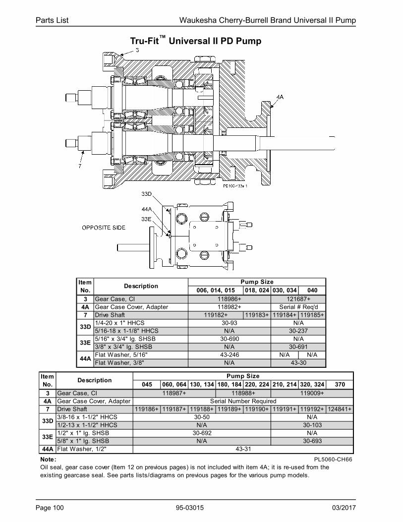
Parts List Waukesha Cherry-Burrell Brand Universal II Pump
Tru-Fit™ Universal II PD Pump
018, 024 030, 034 040
3 Gear Case, CI4A Gear Case Cover, Adapter7 Drive Shaft 119183+ 119184+ 119185+
1/4-20 x 1" HHCS5/16-18 x 1-1/8" HHCS5/16" x 3/4" lg. SHSB3/8" x 3/4" lg. SHSBFlat Washer, 5/16" N/A N/AFlat Washer, 3/8"
045 060, 064 130, 134 180, 184 220, 224 210, 214 320, 324 370
3 Gear Case, CI4A Gear Case Cover, Adapter7 Drive Shaft 119186+ 119187+ 119188+ 119189+ 119190+ 119191+ 119192+ 124841+
3/8-16 x 1-1/2" HHCS1/2-13 x 1-1/2" HHCS1/2" x 1" lg. SHSB5/8" x 1" lg. SHSB
44A Flat Washer, 1/2"
Note: PL5060-CH66
Oil seal, gear case cover (Item 12 on previous pages) is not included with item 4A; it is re-used from the existing gearcase seal. See parts lists/diagrams on previous pages for the various pump models.
43-31
30-103N/A
30-693N/A
30-50N/A
006, 014, 015Pump Size
118986+118982+
N/A43-246
121687+Serial # Req'd
30-237
33E
33D
118987+ 118988+
30-692
Serial Number Required
N/A
ItemNo.
Description
33E
44A43-30
Pump Size
30-690
N/A
ItemNo.
Description
33D
119009+
30-691N/A
119182+30-93N/A
N/A
Page 100 95-03015 03/2017

Waukesha Cherry-Burrell Brand Universal II Pump Parts List
Special Tools
Non-Marring Socket Tool for Rotor Nuts
Model UII Pumps Part Number
006, 014, 015, 018 126533+
030, 034, 040 126534+
045, 060, 064, 130, 134 126257+
180, 184, 220, 224 126535+
210, 213, 214, 320, 323, 324 126536+
PL5060-CH116
Gear Nut Driver, Gear End Shaft Thread ChaserDescription Model UII Pumps Part Number
Gear Nut Driver 006, 014, 015, 018 109281+
Gear Nut Driver 030, 034, 040 109282+
Gear Nut Driver 045, 060, 064, 130, 134 109283+
Gear Nut Driver 180, 184, 220, 224 POA
Gear Nut Driver 210, 213, 214, 320, 323, 324 POA
Gear End Shaft Thread Chaser 006, 014, 015, 018 109287+
Gear End Shaft Thread Chaser 030, 034, 040 109288+
Gear End Shaft Thread Chaser 045, 060, 064, 130, 134 109289+
Gear End Shaft Thread Chaser 180, 184, 220, 224 110305+
Gear End Shaft Thread Chaser 210, 213, 214, 320, 323, 324 POAPL5060-CH129
O-ring Removal ToolDescription Part Number
O-ring removal tool AD0096001PL5060-CH130
03/2017 95-03015 Page 101

Pump Dimensions Waukesha Cherry-Burrell Brand Universal II Pump
Pump Dimensions
Universal II PD Pump Dimensions
INLET(THIS SIDE)
CP3 PNEUMATIC VENTED COVER-DIAPHRAGMCP4 MANUAL VENTED COVER
CP2 PNEUMATIC VENTED COVER-PISTONCP1 JACKETED COVER
CP STANDARD COVER
G112 PLACES
H1T1
SS1
S1
PO
RT
C L
VIEW A-A OF TOP & BOTTOMPUMP MOUNTING PADS
OUTLET (OTHER SIDE)
J
M
OPTIONAL MOUNTINGPAD LOCATION
TYPS
A
AAFRB
I
U
J
N
M
D
K-KEY
OPTIONAL UPPER SHAFTAA
T HL
060U2-MODELSBOLTS,EYE
E GE
O
PORT
AO
X
2X
SIDE MOUNTMOUNTINGPADM
J
320U2
PD100-535a
UII Model
A AA AO B CP CP1 CP2 CP3 CP4 D E F G G1
inch 4.75 1.95 8.3 3.75 11.71 13.92 13.2 13.29 14.92 5.5 1.94 2.31 .41, slot 5/16-18x.62mm 121 50 211 95 297 354 335 338 379 140 49 59 10, slot -inch 4.75 1.95 8.3 3.75 11.71 13.92 13.2 13.29 14.92 5.5 1.94 2.31 .41, slot 5/16-18x.62mm 121 50 211 95 297 354 335 338 379 140 49 59 10 slot -inch 4.75 2.18 8.3 3.75 12.37 14.59 13.86 13.95 15.58 5.5 1.94 2.31 .41, slot 5/16-18x.62mm 121 55 211 95 314 371 352 354 396 140 49 59 10 slot -inch 6.25 2.78 10.29 4.25 14.49 16.49 15.89 15.98 17.58 6.86 2.31 2.56 .41, slot 3/8-16x.62mm 159 71 261 108 368 419 404 406 447 174 59 65 10 slot -inch 6.25 2.99 10.29 4.25 14.87 16.87 16.27 16.36 17.96 6.86 2.31 2.56 .41, slot 3/8-16x.62mm 159 76 261 108 378 428 413 416 456 174 59 65 10 slot -inch 8.25 3.86 15.31 5.87 18.59 20.7 20.68 20.97 22.28 9.56 3.50 4.12 .53, slot 1/2-13x.88mm 210 98 389 149 472 526 525 533 566 243 89 105 13, slot -inch 8.25 4.14 15.31 5.87 19.14 21.25 21.23 21.52 22.83 9.56 3.50 4.12 0.53 1/2-13x.88mm 210 105 389 149 486 540 539 547 580 243 89 105 13 -inch 8.25 4.78 15.31 5.87 20.15 22.27 22.25 22.53 23.84 9.56 3.50 4.12 0.53 1/2-13x.88mm 210 121 389 149 512 566 565 572 606 243 89 105 13 -inch 8.5 3.45 19.13 9 23.26 25.32 26.71 N/A 28.51 12.38 3.75 7.25 .53, slot 1/2-13x.88mm 216 88 486 229 591 643 678 - 724 314 95 184 13, slot -inch 12 3.45 22.38 11.63 27.08 28.58 - - - 13.88 5.25 8.00 0.66 1/2-13x.88mm 305 88 568 295 688 726 - - - 353 133 203 17 -inch 12 3.45 22.38 11.6 27.08 - - - - 13.88 5.25 8.00 0.66 1/2-13x.88mm 305 88 568 295 688 - - - - 353 133 203 17 -inch 8.5 3.69 19.13 9 24 26.06 27.45 29.25 12.38 3.75 7.25 .53, slot 1/2-13x.88mm 216 94 486 229 610 662 713 743 314 95 184 13, slot -inch 12 3.84 22.38 11.6 27.66 29.16 - - - 13.88 5.25 8.00 0.66 1/2-13x.88mm 305 97 568 295 703 741 - - - 353 133 203 17 -inch 12 4.53 22.38 11.63 29.16 30.66 - - - 13.88 5.25 8.00 0.66 1/2-13x.88mm 305 115 568 295 741 779 - - - 353 133 203 17 -
PD100-534
6
15
18
30
40
45
60
220
320
370
130
180
210
213
Page 102 95-03015 03/2017

Waukesha Cherry-Burrell Brand Universal II Pump Pump Dimensions
UII Model
H H1 I JK
+002-.000
L M N OPort Size
R S S1 SS1 T T1U
+002-.000
X 2X
inch 2.50 2.50 7.66 2.93 .1875 9.61 2.12 2 4.21 1" 2.79 1.00 1.00 1.00 2.51 2.51 0.88 3.49 6.97mm 64 64 194 74 4.76 244 54 51 107 -- 71 25 25 25 64 64 22.2 89 177inch 2.50 2.50 7.66 2.93 .1875 9.61 2.12 2.00 4.21 1-1/2" 2.79 1.00 1.00 1.00 2.51 2.51 0.88 3.49 6.97mm 64 64 194 74 4.76 244 54 51 107 -- 71 25 25 25 64 64 22.2 89 177inch 2.50 2.50 7.66 2.93 .1875 9.84 2.12 2.00 4.21 1-1/2" 3.02 1.00 1.00 1.00 2.74 2.51 0.88 3.55 7.09mm 64 64 194 74 4.76 250 54 51 107 -- 77 25 25 25 70 64 22.2 89 177inch 1.81 2.75 8.83 3.56 0.25 11.61 2.62 2.32 5.21 1-1/2" 3.84 1.12 1.12 1.12 4.00 3.59 1.25 4.25 8.50mm 46 70 224 90 6.35 295 67 59 132 -- 98 28 28 28 102 91 31.8 108 216inch 1.81 2.75 8.83 3.56 0.25 11.99 2.62 2.32 5.21 2" 4.00 1.12 1.12 1.12 4.38 3.97 1.25 4.31 8.62mm 46 70 224 90 6.35 305 67 59 132 -- 102 28 28 28 111 101 31.8 109 219inch 3.00 4.13 10.99 5.06 0.38 14.86 3.50 2.25 7.31 2' 4.73 1.75 2.00 1.75 5.34 5.01 1.63 5.37 10.75mm 76 105 279 129 9.525 377 89 57 186 -- 120 44 51 44 136 127 41.3 136 273inch 3.00 4.13 10.99 5.06 0.38 15.14 3.50 2.25 7.31 2-1/2" 5.01 1.75 2.00 1.75 5.62 5.01 1.63 5.4 10.75mm 76 105 279 129 9.53 385 89 57 186 -- 127 44 51 44 143 127 41.3 136 273inch 3.00 4.13 10.99 5.06 0.38 15.77 3.50 2.25 7.31 3" 5.65 1.75 2.00 1.75 6.25 5.66 1.63 5.4 10.75mm 76 105 279 129 9.53 401 89 57 186 -- 144 44 51 44 159 144 41.3 136 273inch 5.38 5.38 14.80 6.38 0.5 18.25 4.50 2.75 9.38 3" 4.20 2.69 2.69 2.69 5.76 6.00 2.00 6.53 13.06mm 137 137 376 162 12.7 464 114 70 238 -- 107 68 68 68 146 152 50.8 168 332inch 5.38 5.38 17.80 6.88 0.63 21.24 5.06 4.06 10.38 4" 4.70 2.69 2.69 2.69 7.83 7.83 2.38 7.37 14.73mm 137 137 452 175 15.9 539 129 103 264 -- 119 68 68 68 199 199 60.45 187 374
inch 5.38 5.38 17.80 6.88 0.625 21.24 5.06 4.06 10.384" 300#
FLG4.70 2.69 2.69 2.69 7.83 7.83 2.38 8.6 17.3
mm 137 137 452 175 15.9 539 129 103 264 -- 119 68 68 68 199 199 60.5 219 438inch 5.38 5.38 14.80 6.38 0.50 18.49 4.50 2.75 9.38 4" 4.44 2.69 2.69 2.69 6.00 6.00 2.00 6.63 13.25mm 137 137 376 162 12.7 470 114 70 238 -- 113 68 68 68 152 152 50.80 168 337
inch 5.38 5.38 17.80 6.88 0.63 21.63 5.06 4.03 10.386" 150#
FLG5.09 2.69 2.69 2.69 8.22 8.22 2.38 8.00 16.00
mm 137 137 452 175 15.9 549 129 103 264 -- 129 68 68 68 209 209 60.5 203 406
inch 5.38 5.38 17.80 6.88 0.63 22.32 5.06 4.06 10.386" 150#
FLG5.78 2.69 2.69 2.69 8.91 8.91 2.38 8.50 17.00
mm 137 137 452 175 15.9 567 129 103 264 -- 147 68 68 68 226 226 60.5 216 432PD100-534b
Note:Dimensions 'X' and '2X' apply for bevel seat, 'S' Clamp, 'Q' Clamp, 15I and 14I fittings (except 213UII & 320UII).CP= Standard Cover, CP1= Jacketed Cover, CP4= Manual Vented Cover. Connection Sizes for Jacketed Covers are 3/4" NPT on Models 006 to 030UII; 1" NPT on Models 045 to 370UII.
6
15
18
30
40
45
60
130
320
370
180
210
213
220
Universal II PD Pump Dimensions
03/2017 95-03015 Page 103

Pump Dimensions Waukesha Cherry-Burrell Brand Universal II Pump
A A
OUTL
ET O
NLY
LP
OR
T C
LL
SSS
SS S
CP2 PNEUMATIC VENTED COVER-PISTON
CP4 MANUAL VENTED COVER
CP STANDARD COVERL
T HB
K-KEYN
U
J
LDHD
IBAA
R F
CP3 PNEUMATIC VENTED COVER-DIAPHRAGM
CP1 JACKETED COVER
PA
PD PB
STYLE FOR MODEL 014 ONLY
S1
T1
S1
HB1O
UTL
ET
PO
RT
CL
VIEW A-A OF SIDEPUMP MOUNTING PAD
MODELS 014, 5/16-18
MODELS 064-224, 1/2-13MODELS 034, 3/8-16
SMLH DRIVESTANDARD
Z
P - NOMINAL
2X
X
AOL
HAO
H
EQ
A
Q
.38 (10), MODEL 014U2
.50 (13), MODELS 034U2, 064U2, 134U2, 224U2.63 (16), MODEL 184U21.00 (25), MODELS 214U2, 324U2
CC CB
FBC
CA FA
HA
PC
PA
PD PB
CENTER HOLES ON MODELS184U2, 214U2, AND 324U2
PD100-536
Rectangular Flange Universal II PD Pump Dimensions
Page 104 95-03015 03/2017

Waukesha Cherry-Burrell Brand Universal II Pump Pump Dimensions
UII RFModel
A AA AOL B C CA CB CC CP CP1 CP4 DL E F FA
inch 6.75 1.95 12.5 4.13 0.5 1.62 6.5 0.5 11.71 13.92 14.92 8.88 0.38 2.31 2.63mm 171 50 318 105 13 41 165 13 297 354 379 226 10 59 67inch 8 2.88 12.75 4.25 0.62 1.88 10.75 0.62 14.49 16.49 17.58 8.88 0.38 3 3.12mm 203 73 324 108 16 48 273 16 368 419 447 226 10 76 79inch 11.75 4.35 13.94 7 0.5 4 12.2 0.52 19.14 21.25 22.83 9 0.5 5.5 5mm 298 110 354 178 13 102 310 13 486 540 580 229 13 140 127inch 11.75 5 13.94 7 0.78 3 14 0.63 20.15 22.27 23.84 9 0.5 5.5 4.55mm 298 127 354 178 20 76 356 16 512 566 606 229 13 140 116inch 15 4.32 20.75 9.5 0.63 5.75 16.75 0.63 23.26 25.32 28.51 13.5 0.63 8.25 7mm 381 110 527 241 16 146 425 16 591 643 724 343 16 210 178inch 18 4.38 35.94 12 0.75 7.5 16.5 0.75 27.08 28.58 - 27.13 0.75 9.5 9mm 457 111 913 305 19 190 419 19 688 726 - 689 19 241 229inch 15 4.75 19.75 9.5 0.63 4.37 16.75 0.63 24 26.06 29.25 13.5 0.63 8.25 5.62mm 381 121 502 241 16 111 425 16 610 662 743 343 16 210 143inch 18 4.79 35.94 12 0.81 8 16.5 0.75 27.66 29.16 - 27.13 0.75 9.5 9.63mm 457 122 913 305 21 203 419 19 703 741 - 689 19 241 245
UII RFModel
FB H HA I J L PA PB PC PD U X 2X
inch 7.5 0.41 0.41 7.66 2.12 9.61 1.44 4.94 0.59 1.28 0.875 3.63 7.11mm 191 10 10 195 54 244 37 125 15 33 22.23 92 181inch 12 0.44 0.53 8.49 2.62 11.36 1.81 6.84 0.66 2.58 1.25 3.88 8.12mm 305 11 13 216 67 289 46 174 17 66 31.75 99 206inch 13.23 0.56 0.53 10.77 3.5 15.16 2.44 9 1.28 2.11 1.625 4.94 10.31mm 336 14 13 274 89 385 62 229 33 54 41.28 125 262inch 15.25 0.56 0.53 10.77 3.5 15.78 3.19 9.38 0.68 2.94 1.625 4.94 10.31mm 387 14 13 274 89 401 81 238 17 75 41.28 125 262inch 18 0.56 0.53 13.74 4.5 18.31 3.28 11.25 1.86 3.38 2 7.25 13.78mm 457 14 13 349 114 465 83 286 47 86 50.8 184 350inch 18 0.69 0.69 16.86 5.06 21.26 3.45 12.7 2.78 2.65 2.375 8.81 16.17mm 457 18 18 428 129 540 88 323 71 67 60.33 224 411inch 18 0.56 0.53 13.74 4.5 18.49 4.06 11.25 0.78 3.38 2 6.25 12.87mm 457 14 13 349 114 470 103 286 20 86 50.8 159 327inch 18 0.69 0.69 16.86 5.06 21.63 4.25 12.7 2.69 2.65 2.375 8.81 17.81mm 457 18 18 428 129 549 108 323 68 67 60.33 224 452
PD100-537
Note:Dimension '2X' applies for bevel seat, 'S' Clamp, 'Q' Clamp, 15I and 14I fittings.CP= Standard Cover, CP1= Jacketed Cover, CP4= Manual Vented Cover. Connection Sizes for Jacketed Covers are 3/4" NPT on Models 014 to 034; 1" NPT on Models 064-324.
4"
P
1-1/2"--2"--
2-1/2"
14
34
64
134
184
--64
--
--4"--6"
3"--3"--
134
184
214
224
324
214
224
324
14
34
Rectangular Flange Universal II PD Pump Dimensions
03/2017 95-03015 Page 105

Pump Dimensions Waukesha Cherry-Burrell Brand Universal II Pump
Tru-Fit ™ Universal II PD Pump Dimensions
Table of Dimensions
UII
ModelA B C D 2 E F G H J K L M 1 N 1 P 1 S T T1
Port
SizeU V
in. 12.0 10.0 9.15 6.97 7.87 13.25 2.01 18.0 2.11 10.08 12.19 27.31 15.56 10.92 5.44 2.12 2.51 1-1/2" 5/16-18 x .62 2.0
mm 305 254 232 177 200 337 51 457 54 256 310 394 395 227 138 54 64 -- N/A 51
in. 12.0 10.0 9.15 6.97 7.87 13.25 2.01 18.0 2.11 10.08 12.19 27.31 15.56 10.92 5.44 2.12 2.51 1-1/2" 5/16-18 x .62 2.0
mm 304 254 232 177 200 337 51 457 54 256 310 694 395 227 138 54 64 -- N/A 51
in. 12.0 10.0 9.15 7.10 7.87 13.25 2.25 18.0 2.54 10.31 12.85 27.31 15.56 10.92 5.44 2.12 2.51 1-1/2" 5/16-18 x .62 2.0
mm 304 254 232 180 200 337 57 457 65 262 326 694 395 227 138 54 64 -- N/A 51
in. 14.0 12.0 10 8.51 8.37 15.11 2.59 20.0 2.87 12.47 15.34 33.57 18.65 13.74 5.81 2.62 3.59 1-1/2" 3/8-16 x .62 2.25
mm 356 304 255 216 213 384 66 508 73 317 390 853 474 349 148 67 91 -- N/A 57
in. 14.0 12.0 10 8.62 8.37 15.11 2.97 20.0 2.87 12.84 15.71 33.94 18.65 13.74 5.81 2.62 3.97 2" 3/8-16 x .62 2.25
mm 356 305 255 219 213 384 75 508 73 326 399 862 474 349 148 67 101 -- N/A 57
in. 18.0 16.0 12.0 10.74 9.75 20.0 2.73 28.0 4.0 17.11 21.11 43.72 22.02 17.16 8.13 3.5 5.01 2" 1/2-13 x .88 3.5
mm 457 406 305 273 248 508 69 711 102 435 536 1110 559 436 207 89 127 -- N/A 89
in. 18.0 16.0 12.0 10.74 9.75 20.0 3.01 28.0 4.0 17.39 21.39 44.0 22.02 17.16 8.13 3.5 5.01 2-1/2" 1/2-13 x .88 3.5
mm 457 406 305 273 248 508 76 711 102 442 543 1118 559 436 207 89 127 -- N/A 89
in. 18.0 16.0 12.0 10.74 9.75 20.0 3.64 28.0 4.38 18.02 22.4 45.01 22.02 17.16 8.13 3.5 5.66 3" 1/2-13 x .88 3.5
mm 457 406 305 273 248 508 92 711 111 458 569 1143 559 436 207 89 144 -- N/A 89
in. 20.0 18.0 14.5 13.06 11.5 23.25 3.27 36.0 4.99 19.52 24.51 50.02 25.91 18.82 10.0 4.5 6 3" 1/2-13 x 1.0 5.38
mm 508 457 368 332 292 591 83 914 127 496 623 1271 658 478 254 114 152 -- N/A 137
in. 20.0 18.0 14.5 13.25 11.5 23.25 3.51 36.0 5.49 19.76 25.25 50.76 25.91 18.82 10.0 4.5 6 4" 1/2-13 x 1.0 5.38
mm 508 457 368 337 292 591 89 914 139 502 641 1289 658 478 254 114 152 -- N/A 137
PD100-4391
060
130
180
220
006
015
018
030
040
045
1 Dimensions affected by motor frame size
2 Dimensions affected by connection type
L P
M
H
E
G
J
F
K
B/2
B
A
C
D
T1 S
T
U (3) TAPPEDHOLES
V
V/2
NPort Size
PD100-438b
Page 106 95-03015 03/2017

Waukesha Cherry-Burrell Brand Universal II Pump ATEX Certification
03/2017 95-03015 Page 107
ATEX Supplement to Universal II Operation Manuals
1. ATEX declaration of conformity must be included with operational manual.
2. Sight glass in gear case is not approved; black plugs must be installed on all drain/level ports.
3. Only Waukesha Cherry-Burrell brand spare parts are allowed to be installed into the pump. Use of non-Waukesha Cherry-Burrell brand parts will void ATEX approval.

Maintenance Summary Waukesha Cherry-Burrell Brand Universal II Pump
Page 108 95-03015 03/2017
Universal II Maintenance Summary Reference Sheet
Universal II Model
Change oil every 750 hours*ISO Grade 320, SAE 140 or AGMA Number 6EP
Grease bearings every 750 hours*NLGI Grade No. 2, EP, Lithium-based grease.
* Aggressive washdown or extreme running conditions may require more frequent lubrication intervals.
Oil Capacity (Gears) Grease Quantity (per Bearing)
Top or Bottom Side Mount Front Rear
006, 014, 015, 018 1.3 oz (40 ml) 3.3 oz (100 ml) 0.37 oz (11 cc) 0.13 oz (4 cc)
030, 034, 040 2.0 oz (60 ml) 4 oz (120 ml) 0.60 oz (18 cc) 0.21 oz (6 cc)
045, 060, 064, 130, 134 6.0 oz (170 ml) 9.5 oz (280 ml) 0.84 oz (25 cc) 0.76 oz (22 cc)
180, 184, 220, 224 11 oz (320 ml) 20 oz (600 ml) 1.33 oz (39 cc) 1.03 oz (30 cc)
210, 213, 214, 320, 323, 324, 370
17 oz (500 ml) 44 oz (1300 ml) 1.96 oz (58 cc) 1.16 oz (34 cc)
Universal II Model
Torque Values - Locknuts Universal II Wrench Size
Rotor Cover Rotor NutBody
Retaining Cap Screw
Cover Nut
006, 015, 018 50 ft lbs (68 N·m) 7 ft lbs (10 N·m) 15/16"3/16"
5/8"
030, 040 120 ft lbs (163 N·m) 11 ft lbs (15 N·m) 1-1/4" 5/8"
045, 060250 ft lbs (339 N·m)
56 ft lbs (76 N·m)1-5/8" 1/4" 7/8"
130 25 ft lbs (34 N·m)
180, 220 325 ft lbs (441 N·m) 110 ft lbs (149 N·m) 2-1/4"5/16"
7/8"
210, 213, 320, 323, 370
375 ft lbs (508 N·m) 158 ft lbs (214 N·m) 2-3/8" 1"
Universal II Model
Rotor Type: Std & FF Hot Std & FF Hot Standard FF & Hot0.0015 - 0.002 0.0015 - 0.002 0.001 - 0.004 0.0025 - 0.0055 0.004 - 0.006 0.0055 - 0.0075
(0.04 - 0.05) (0.04 - 0.05) (0.03 - 0.10) (0.06 - 0.14) (0.10 - 0.15) (0.14 - 0.19)0.0015 - 0.002 0.0015 - 0.002 0.001 - 0.004 0.0025 - 0.0055 0.004 - 0.0065 0.006 - 0.0085
(0.04 - 0.05) (0.04 - 0.05) (0.03 - 0.10) (0.06 - 0.14) (0.10 - 0.17) (0.15 - 0.22)0.002 - 0.0025 0.002 - 0.0025 0.001 - 0.005 0.0025 - 0.006 0.0035 - 0.006 0.0065 - 0.009
(0.05 - 0.06) (0.05 - 0.06) (0.03 - 0.13) (0.06 - 0.15) (0.09 - 0.15) (0.17 - 0.23)0.003 - 0.0035 0.003 - 0.0035 0.003 - 0.0075 0.005 - 0.010 0.0045 - 0.009 0.0085 - 0.014
(0.08 - 0.09) (0.08 - 0.09) (0.08 - 0.19) (0.13 - 0.25) (0.11 - 0.23) (0.22 - 0.36)0.003 - 0.0035 0.003 - 0.0035 0.0035 - 0.0075 0.0055 - 0.0095 0.0045 - 0.009 0.009 - 0.015
(0.08 - 0.09) (0.08 - 0.09) (0.09 - 0.19) (0.14 - 0.24) (0.11 - 0.23) (0.23 - 0.38)0.004 - 0.005 0.004 - 0.005 0.0055 - 0.0095 0.009 - 0.013 0.005 - 0.010 0.010 - 0.015 (0.10 - 0.13) (0.10 - 0.13) (0.14 - 0.24) (0.23 - 0.33) (0.13 - 0.25) (0.25 - 0.38)0.005 - 0.006 0.005 - 0.006 0.008 - 0.012 0.010 - 0.014 0.007 - 0.012 0.013 - 0.018(0.13 - 0.15) (0.13 - 0.15) (0.20 - 0.30) (0.25 - 0.36) (0.18 - 0.30) (0.33 - 0.46)0.005 - 0.006 0.005 - 0.006 0.009 - 0.013 0.011 - 0.015 0.007 - 0.012 0.013 - 0.018(0.13 - 0.15) (0.13 - 0.15) (0.23 - 0.33) (0.28 - 0.38) (0.18 - 0.30) (0.33 - 0.46)
Std = Standard Clearance Rotors; FF = Front Faced Clearance Rotors; Hot = Hot Clearance Rotors PD100-600a
Standard Rotors: -40°F (-40°C) to 180°F (82°C); FF Clearance Rotors: 180°F (82°C) to 200°F (93°C); Hot Clearance Rotors: -40°F (-40°C) to 300°F (149°C). Contact SPX FLOW Application Engineering if alternate rotors are needed. NOTE: The assembly clearances stated above are for reference only. Actual pump clearances may vary based on pump performance testing
A - Back Facein (mm)
B - Rotor to Bodyin (mm)
C - Front Facein (mm)
006
014, 015, 018
030, 034, 040
045, 060, 064
130, 134
180, 184, 220, 224
210, 213, 214, 320, 323, 324
370

Waukesha Cherry-Burrell Brand Universal II Pump Maintenance Summary
��
�
Universal II Maintenance Summary Reference Sheet - Copy for optional removalUniversal II Model
Change oil every 750 hours*ISO Grade 320, SAE 140 or AGMA Number 6EP
Grease bearings every 750 hours*NLGI Grade No. 2, EP, Lithium-based grease.
* Aggressive washdown or extreme running conditions may require more frequent lubrication intervals.
Oil Capacity (Gears) Grease Quantity (per Bearing)
Top or Bottom Side Mount Front Rear
006, 014, 015, 018 1.3 oz (40 ml) 3.3 oz (100 ml) .37 oz (11 cc) .13 oz (4 cc)
030, 034, 040 2.0 oz (60 ml) 4 oz (120 ml) .60 oz (18 cc) .21 oz (6 cc)
045, 060, 064, 130, 134 6.0 oz (170 ml) 9.5 oz (280 ml) .84 oz (25 cc) .76 oz (22 cc)
180, 184, 220, 224 11 oz (320 ml) 20 oz (600 ml) 1.33 oz (39 cc) 1.03 oz (30 cc)
210, 213, 214, 320, 323, 324, 370
17 oz (500 ml) 44 oz (1300 ml) 1.96 oz (58 cc) 1.16 oz (34 cc)
Universal II Model
Torque Values - Locknuts Universal II Wrench Size
Rotor Cover Rotor NutBody
Retaining Cap Screw
Cover Nut
006, 015, 018 50 ft lbs (68 N·m) 7 ft lbs (10 N·m) 15/16"3/16"
5/8"
030, 040 120 ft lbs (163 N·m) 11 ft lbs (15 N·m) 1-1/4" 5/8"
045, 060250 ft lbs (339 N·m)
56 ft lbs (76 N·m)1-5/8" 1/4" 7/8"
130 25 ft lbs (34 N·m)
180, 220 325 ft lbs (441 N·m) 110 ft lbs (149 N·m) 2-1/4"5/16"
7/8"
210, 213, 320, 323, 370
375 ft lbs (508 N·m) 158 ft lbs (214 N·m) 2-3/8" 1"
Universal II Model
Rotor Type: Std & FF Hot Std & FF Hot Standard FF & Hot0.0015 - 0.002 0.0015 - 0.002 0.001 - 0.004 0.0025 - 0.0055 0.004 - 0.006 0.0055 - 0.0075
(0.04 - 0.05) (0.04 - 0.05) (0.03 - 0.10) (0.06 - 0.14) (0.10 - 0.15) (0.14 - 0.19)0.0015 - 0.002 0.0015 - 0.002 0.001 - 0.004 0.0025 - 0.0055 0.004 - 0.0065 0.006 - 0.0085
(0.04 - 0.05) (0.04 - 0.05) (0.03 - 0.10) (0.06 - 0.14) (0.10 - 0.17) (0.15 - 0.22)0.002 - 0.0025 0.002 - 0.0025 0.001 - 0.005 0.0025 - 0.006 0.0035 - 0.006 0.0065 - 0.009
(0.05 - 0.06) (0.05 - 0.06) (0.03 - 0.13) (0.06 - 0.15) (0.09 - 0.15) (0.17 - 0.23)0.003 - 0.0035 0.003 - 0.0035 0.003 - 0.0075 0.005 - 0.010 0.0045 - 0.009 0.0085 - 0.014
(0.08 - 0.09) (0.08 - 0.09) (0.08 - 0.19) (0.13 - 0.25) (0.11 - 0.23) (0.22 - 0.36)0.003 - 0.0035 0.003 - 0.0035 0.0035 - 0.0075 0.0055 - 0.0095 0.0045 - 0.009 0.009 - 0.015
(0.08 - 0.09) (0.08 - 0.09) (0.09 - 0.19) (0.14 - 0.24) (0.11 - 0.23) (0.23 - 0.38)0.004 - 0.005 0.004 - 0.005 0.0055 - 0.0095 0.009 - 0.013 0.005 - 0.010 0.010 - 0.015 (0.10 - 0.13) (0.10 - 0.13) (0.14 - 0.24) (0.23 - 0.33) (0.13 - 0.25) (0.25 - 0.38)0.005 - 0.006 0.005 - 0.006 0.008 - 0.012 0.010 - 0.014 0.007 - 0.012 0.013 - 0.018(0.13 - 0.15) (0.13 - 0.15) (0.20 - 0.30) (0.25 - 0.36) (0.18 - 0.30) (0.33 - 0.46)0.005 - 0.006 0.005 - 0.006 0.009 - 0.013 0.011 - 0.015 0.007 - 0.012 0.013 - 0.018(0.13 - 0.15) (0.13 - 0.15) (0.23 - 0.33) (0.28 - 0.38) (0.18 - 0.30) (0.33 - 0.46)
Std = Standard Clearance Rotors; FF = Front Faced Clearance Rotors; Hot = Hot Clearance Rotors PD100-600a
Standard Rotors: -40°F (-40°C) to 180°F (82°C); FF Clearance Rotors: 180°F (82°C) to 200°F (93°C); Hot Clearance Rotors: -40°F (-40°C) to 300°F (149°C). Contact SPX FLOW Application Engineering if alternate rotors are needed. NOTE: The assembly clearances stated above are for reference only. Actual pump clearances may vary based on pump performance testing
A - Back Facein (mm)
B - Rotor to Bodyin (mm)
C - Front Facein (mm)
006
014, 015, 018
030, 034, 040
045, 060, 064
130, 134
180, 184, 220, 224
210, 213, 214, 320, 323, 324
370
03/2017 95-03015 Page 109

Maintenance Summary Waukesha Cherry-Burrell Brand Universal II Pump
��
�
Notes
Page 110 95-03015 03/2017


Universal II SeriesROTARY POSITIVE DISPLACEMENT PUMP
SPX FLOW, Inc.
611 Sugar Creek Road
Delavan, WI 53115
P: (262) 728-1900 or (800) 252-5200
F: (262) 728-4904 or (800) 252-5012
SPX FLOW, Inc. reserves the right to incorporate our latest design and material
changes without notice or obligation.
Design features, materials of construction and dimensional data, as described in
this bulletin, are provided for your information only and should not be relied upon
unless confirmed in writing.
Please contact your local sales representative for product availability in your
region. For more information visit www.spxflow.com.
The green “>” is a trademark of SPX FLOW, Inc.
ISSUED: 03/2017
COPYRIGHT © 2017 SPX FLOW, Inc.