Unity Power Factor Discussion Latest version - michigan.gov · Unity Power Factor Discussion at...
17
Unity Power Factor Discussion at MPSC Interconnection Procedures Meeting Adam Jacob – Senior Engineer DTE Energy June 19 th 2007 Meeting Room A
-
Upload
nguyendien -
Category
Documents
-
view
238 -
download
0
Transcript of Unity Power Factor Discussion Latest version - michigan.gov · Unity Power Factor Discussion at...
Unity Power Factor Discussion at MPSC Interconnection Procedures Meeting
Adam Jacob – Senior EngineerDTE Energy
June 19th 2007Meeting Room A
Power Factor• The power factor of an AC electric power
system is defined as the ratio of the real powerto the apparent power, and is a number between 0 and 1.
• Real power is the capacity of the circuit for performing work in a particular time.
• Apparent power is the product of the current and voltage of the circuit.
• Due to energy stored in the load and returned to the source, or due to a non-linear load that distorts the wave shape of the current drawn from the source, the apparent power can be greater than the real power.
More Power Factor definition
• Circuits containing purely resistive heating elements (filament lamps, strip heaters, cooking stoves, etc.) have a power factor of 1.0.
• Circuits containing inductive or capacitive elements ( lamp ballasts, motors, etc.) often have a power factor below 1.0
Power Factor Calculation• AC power flow has the three components: real
power (P), measured in watts (W); apparent power (S), measured in volt-amperes (VA); and reactive power (Q), measured in reactive volt-amperes (VAr).
• The power factor is defined as:P/S .
• If θ is the phase angle between the current and voltage, then the power factor is equal to cos θ , and:
• P = S | cos θ |
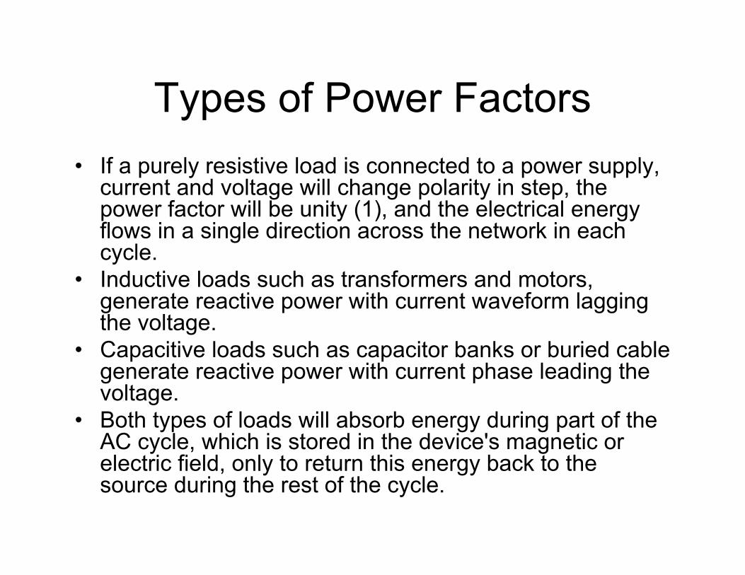
Types of Power Factors• If a purely resistive load is connected to a power supply,
current and voltage will change polarity in step, the power factor will be unity (1), and the electrical energy flows in a single direction across the network in each cycle.
• Inductive loads such as transformers and motors, generate reactive power with current waveform lagging the voltage.
• Capacitive loads such as capacitor banks or buried cable generate reactive power with current phase leading the voltage.
• Both types of loads will absorb energy during part of the AC cycle, which is stored in the device's magnetic or electric field, only to return this energy back to the source during the rest of the cycle.
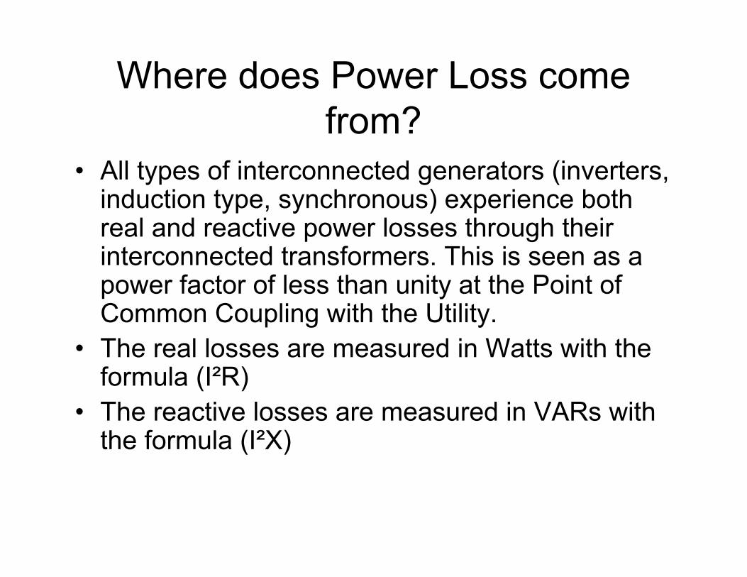
Where does Power Loss come from?
• All types of interconnected generators (inverters, induction type, synchronous) experience both real and reactive power losses through their interconnected transformers. This is seen as a power factor of less than unity at the Point of Common Coupling with the Utility.
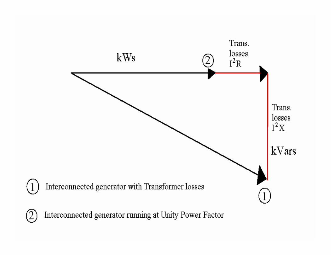
• The real losses are measured in Watts with the formula (I²R)
• The reactive losses are measured in VARs with the formula (I²X)
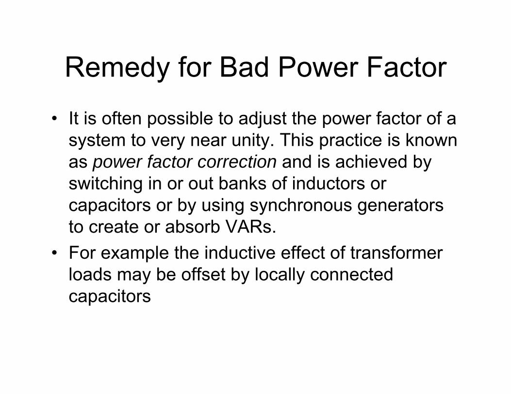
Remedy for Bad Power Factor
• It is often possible to adjust the power factor of a system to very near unity. This practice is known as power factor correction and is achieved by switching in or out banks of inductors or capacitors or by using synchronous generators to create or absorb VARs.
• For example the inductive effect of transformer loads may be offset by locally connected capacitors
Remedy for Bad Power Factor (cont.)
• Most Inverter and Synchronous generators have the capability to dial in the desired power factor of the machine. This results in less real power, but compensates for the I²R and the VAR losses the interconnection transformer.
• Induction machines typically do not have this function. They would require either a capacitor bank or some form of capacitance to offset the reactive power losses

Real World Issues with Non-Unity Power Factors for Interconnected Generators
Generating units running below unity power factor appear as reactive loads on the system.
This requires the utility to compensate for the loss of both real and reactive power due to this condition.
Compensation equates to generating more VARs by the utility generation or adding capacitor banks which is a burden to the utility and its customers.
Basis for Unity PF for Interconnections
The recommendation that interconnected Generators maintain Unity Power Factor isOne of the key recommendations in the “Final Report on the August 14, 2003 Blackout in the US and Canada: Causes and Recommendations”
This document was prepared by the US-Canada Power System Outage Task Force.
Cost to Utility
• The fully loaded cost to the utility for installing capacitor banks for VAR losses is around $20K per MVAR.
• Example: A 2 MW induction generator with a 0.85 power factor has about 1 MVAR of reactive power. This project would require $20K worth of capacitor banks.

What does this all mean?
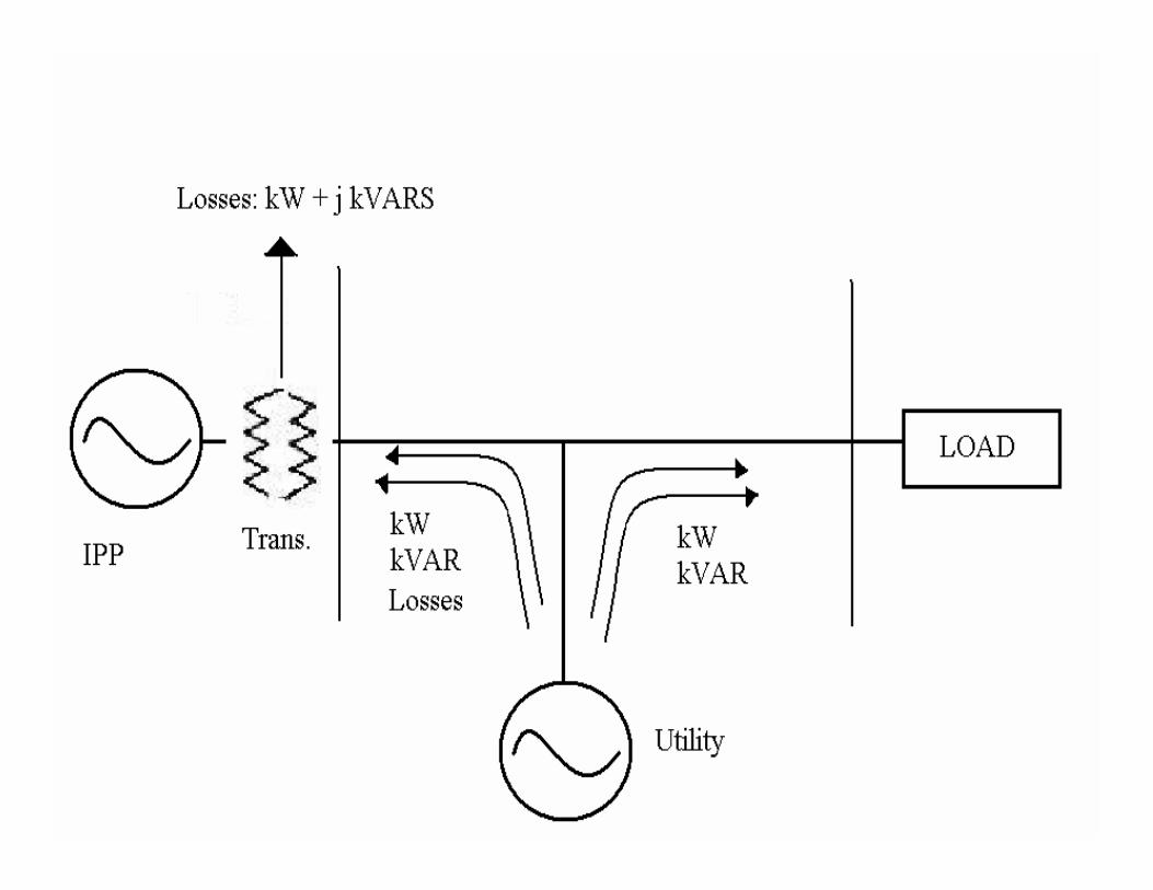
• IPPs who are operating below unity power factor at the Point of Common Coupling are absorbing VARS from the utility, which costs both the utility and rate payers.
• Unless IPPs would like to be billed for their real and reactive transformer losses, they need to operate at unity power factor at the PCC.
• Most Power Factor Correction is easy to implement.