
UNITY MUX 5010 - WEGENER · 2006-11-29 · UMX 5010 USER’S MANUAL 3 800025-01 Rev. D Selectable...
58
800025-01 Rev. D UNITY MUX 5010 PRODUCT DESCRIPTION USER’ S MANUAL
Transcript of UNITY MUX 5010 - WEGENER · 2006-11-29 · UMX 5010 USER’S MANUAL 3 800025-01 Rev. D Selectable...

800025-01 Rev. D
UNITY MUX 5010PRODUCT DESCRIPTION
USER’S MANUAL
UNITY MUX 5010 USER’S MANUAL
800025-01 Rev. D ii www.wegener.com
Data, drawings, and other material contained herein are proprietary to Wegener Communi-cations, Inc., and may not be reproduced or duplicated in any form without the prior written permission of Wegener Communications, Inc.
The information contained herein is subject to change without notice. Revisions may be issued to advise of such changes and/or additions.
WEGENER, COMPEL CONTROL, MEDIAPLAN, ENVOY, UNITY, UNITY·IP, and
iPUMP are trademarks of Wegener Communications, Inc. All other trademarks are the property of their respective owners.
2005 Wegener Communications, Inc. All rights reserved.
Portions copyright 1992-2001 FairCom Corporation. "FairCom" and "c-tree plus" are trademarks of FairCom Corporation and are registered in the United States and other countries. All Rights Reserved.
Correspondence regarding this publication,
800025-01 Revision DFourth Edition: April 2005
should be forwarded to:
Wegener Communications, Inc.Technology Park/Johns Creek11350 Technology CircleDuluth, GA 30097-1502
Phone: 770-814-4000
Fax: 770-623-0698
The Wegener Product Name is approved under FCC Part 15B Class A, UL1950, CSA, and CE. [Elaborate by including specific subsections of appropriate codes, if applicable.]

UMX 5010 User’s Manual
www.wegener.com iii 800025-01 Rev. D
TABLE OF CONTENTS
CHAPTER 1 GENERAL INFORMATION
1.1 Manual Overview . . . . . . . . . . . . . . . . . . . . . . . . . . . . . . . . . . . . . . . . . . . . . . . . . . . . 1
1.2 UMX5010 Overview . . . . . . . . . . . . . . . . . . . . . . . . . . . . . . . . . . . . . . . . . . . . . . . . . . 2
Functional Description. . . . . . . . . . . . . . . . . . . . . . . . . . . . . . . . . . . . . . . . . . . . . . . . . . . . 2
Physical Description . . . . . . . . . . . . . . . . . . . . . . . . . . . . . . . . . . . . . . . . . . . . . . . . 2
1.3 UMX5010 Specifications . . . . . . . . . . . . . . . . . . . . . . . . . . . . . . . . . . . . . . . . . . . . . . 3
1.4 Safety Summary . . . . . . . . . . . . . . . . . . . . . . . . . . . . . . . . . . . . . . . . . . . . . . . . . . . . . 5
1.5 Glossary of Terms and Abbreviations . . . . . . . . . . . . . . . . . . . . . . . . . . . . . . . . . . . . 5
CHAPTER 2 INSTALLATION
2.1 Unpacking and Inspection . . . . . . . . . . . . . . . . . . . . . . . . . . . . . . . . . . . . . . . . . . . . . 7
2.2 Location and Mounting. . . . . . . . . . . . . . . . . . . . . . . . . . . . . . . . . . . . . . . . . . . . . . . . 7FCC-mandated suppression of radiated emissions. . . . . . . . . . . . . . . . . . . . . . . . . 7Rack Mounting . . . . . . . . . . . . . . . . . . . . . . . . . . . . . . . . . . . . . . . . . . . . . . . . . . . . 9Desktop Installation . . . . . . . . . . . . . . . . . . . . . . . . . . . . . . . . . . . . . . . . . . . . . . . . . 9
2.3 UMX5010 Connections . . . . . . . . . . . . . . . . . . . . . . . . . . . . . . . . . . . . . . . . . . . . . . 10
CHAPTER 3 OPERATION
3.1 Operation Overview . . . . . . . . . . . . . . . . . . . . . . . . . . . . . . . . . . . . . . . . . . . . . . . . . 13
3.2 Controls and Indicators . . . . . . . . . . . . . . . . . . . . . . . . . . . . . . . . . . . . . . . . . . . . . . 13
Liquid-crystal Display(LCD) . . . . . . . . . . . . . . . . . . . . . . . . . . . . . . . . . . . . . . . . . . 13Pushbuttons . . . . . . . . . . . . . . . . . . . . . . . . . . . . . . . . . . . . . . . . . . . . . . . . . . . . . 14Front-panel LEDs . . . . . . . . . . . . . . . . . . . . . . . . . . . . . . . . . . . . . . . . . . . . . . . . . 17Rear-panel LEDs. . . . . . . . . . . . . . . . . . . . . . . . . . . . . . . . . . . . . . . . . . . . . . . . . . 19
3.3 Serial Ports. . . . . . . . . . . . . . . . . . . . . . . . . . . . . . . . . . . . . . . . . . . . . . . . . . . . . . . . 19Device assignments . . . . . . . . . . . . . . . . . . . . . . . . . . . . . . . . . . . . . . . . . . . . . . . 19
Device configurations . . . . . . . . . . . . . . . . . . . . . . . . . . . . . . . . . . . . . . . . . . . . . . 20Device handling . . . . . . . . . . . . . . . . . . . . . . . . . . . . . . . . . . . . . . . . . . . . . . . . . . . 20
3.4 Alarm/Warning System . . . . . . . . . . . . . . . . . . . . . . . . . . . . . . . . . . . . . . . . . . . . . . 22Alarm Conditions . . . . . . . . . . . . . . . . . . . . . . . . . . . . . . . . . . . . . . . . . . . . . . . . . . 22Warning Conditions . . . . . . . . . . . . . . . . . . . . . . . . . . . . . . . . . . . . . . . . . . . . . . . . 22
Maskable Alarm and Warning Conditions . . . . . . . . . . . . . . . . . . . . . . . . . . . . . . . 23
3.5 Menu Screens . . . . . . . . . . . . . . . . . . . . . . . . . . . . . . . . . . . . . . . . . . . . . . . . . . . . . 24Default LCD Screens. . . . . . . . . . . . . . . . . . . . . . . . . . . . . . . . . . . . . . . . . . . . . . . 27Home Screen . . . . . . . . . . . . . . . . . . . . . . . . . . . . . . . . . . . . . . . . . . . . . . . . . . . . 27Software Download Screen . . . . . . . . . . . . . . . . . . . . . . . . . . . . . . . . . . . . . . . . . . 28Warning/Alarm Screen . . . . . . . . . . . . . . . . . . . . . . . . . . . . . . . . . . . . . . . . . . . . . 29
EMAIL . . . . . . . . . . . . . . . . . . . . . . . . . . . . . . . . . . . . . . . . . . . . . . . . . . . . . . . . . . 30CA Override. . . . . . . . . . . . . . . . . . . . . . . . . . . . . . . . . . . . . . . . . . . . . . . . . . . . . . 31Transport Input Setup . . . . . . . . . . . . . . . . . . . . . . . . . . . . . . . . . . . . . . . . . . . . . . 31Injected Stream Setup. . . . . . . . . . . . . . . . . . . . . . . . . . . . . . . . . . . . . . . . . . . . . . 32
COMPEL Input . . . . . . . . . . . . . . . . . . . . . . . . . . . . . . . . . . . . . . . . . . . . . . . . 32CA Input . . . . . . . . . . . . . . . . . . . . . . . . . . . . . . . . . . . . . . . . . . . . . . . . . . . . . 32AUX Data Input . . . . . . . . . . . . . . . . . . . . . . . . . . . . . . . . . . . . . . . . . . . . . . . . 33Conditional Access Setup . . . . . . . . . . . . . . . . . . . . . . . . . . . . . . . . . . . . . . . . 33
UMX 5010 User’s Manual
800025-01 Rev. D iv www.wegener.com
CA Type . . . . . . . . . . . . . . . . . . . . . . . . . . . . . . . . . . . . . . . . . . . . . . . . . . . . . 34Partition Scrambling . . . . . . . . . . . . . . . . . . . . . . . . . . . . . . . . . . . . . . . . . . . . 34CA scrambler partition PID . . . . . . . . . . . . . . . . . . . . . . . . . . . . . . . . . . . . . . . 34Encryption Control Table . . . . . . . . . . . . . . . . . . . . . . . . . . . . . . . . . . . . . . . . . 34Fixed Key Encryption . . . . . . . . . . . . . . . . . . . . . . . . . . . . . . . . . . . . . . . . . . . 35PIN Scrambling Key . . . . . . . . . . . . . . . . . . . . . . . . . . . . . . . . . . . . . . . . . . . . 35
Carrier ID Tags Setup . . . . . . . . . . . . . . . . . . . . . . . . . . . . . . . . . . . . . . . . . . . . . . 35Serial Inputs Setups. . . . . . . . . . . . . . . . . . . . . . . . . . . . . . . . . . . . . . . . . . . . . . . . 36
Aux/Term Port Device Selection . . . . . . . . . . . . . . . . . . . . . . . . . . . . . . . . . . . 36Unit ID, for Daisy-chain shared serial bus . . . . . . . . . . . . . . . . . . . . . . . . . . . . 37Serial Device Setups . . . . . . . . . . . . . . . . . . . . . . . . . . . . . . . . . . . . . . . . . . . . 38Serial Device Settings . . . . . . . . . . . . . . . . . . . . . . . . . . . . . . . . . . . . . . . . . . . 38
Miscellaneous Setups . . . . . . . . . . . . . . . . . . . . . . . . . . . . . . . . . . . . . . . . . . . . . . 38Unit Front-panel Label . . . . . . . . . . . . . . . . . . . . . . . . . . . . . . . . . . . . . . . . . . . 39Indicator Response Times. . . . . . . . . . . . . . . . . . . . . . . . . . . . . . . . . . . . . . . . 39User (solid-state) Contact Closures. . . . . . . . . . . . . . . . . . . . . . . . . . . . . . . . . 40Application Software Switch . . . . . . . . . . . . . . . . . . . . . . . . . . . . . . . . . . . . . . 40Reset Unit . . . . . . . . . . . . . . . . . . . . . . . . . . . . . . . . . . . . . . . . . . . . . . . . . . . . 41
Unit Status . . . . . . . . . . . . . . . . . . . . . . . . . . . . . . . . . . . . . . . . . . . . . . . . . . . . . . . 41ASI Transport . . . . . . . . . . . . . . . . . . . . . . . . . . . . . . . . . . . . . . . . . . . . . . . . . 41COMPEL Stream. . . . . . . . . . . . . . . . . . . . . . . . . . . . . . . . . . . . . . . . . . . . . . . 42CA Stream. . . . . . . . . . . . . . . . . . . . . . . . . . . . . . . . . . . . . . . . . . . . . . . . . . . . 42Aux Data Stream . . . . . . . . . . . . . . . . . . . . . . . . . . . . . . . . . . . . . . . . . . . . . . . 43Serial Data Injection Buffer . . . . . . . . . . . . . . . . . . . . . . . . . . . . . . . . . . . . . . . 43Transport Stream Status . . . . . . . . . . . . . . . . . . . . . . . . . . . . . . . . . . . . . . . . . 44Time since log cleared . . . . . . . . . . . . . . . . . . . . . . . . . . . . . . . . . . . . . . . . . . 44Clear Logs . . . . . . . . . . . . . . . . . . . . . . . . . . . . . . . . . . . . . . . . . . . . . . . . . . . . 44
Network Control Status . . . . . . . . . . . . . . . . . . . . . . . . . . . . . . . . . . . . . . . . . . . . . 45Current Version Information . . . . . . . . . . . . . . . . . . . . . . . . . . . . . . . . . . . . . . . . . . 46Navigation Help . . . . . . . . . . . . . . . . . . . . . . . . . . . . . . . . . . . . . . . . . . . . . . . . . . . 48
3.6 Terminal/Modem Mode. . . . . . . . . . . . . . . . . . . . . . . . . . . . . . . . . . . . . . . . . . . . . . . 50Daisy chain terminal communication . . . . . . . . . . . . . . . . . . . . . . . . . . . . . . . . . . . 50Overview and syntax . . . . . . . . . . . . . . . . . . . . . . . . . . . . . . . . . . . . . . . . . . . . . . . 50User Commands . . . . . . . . . . . . . . . . . . . . . . . . . . . . . . . . . . . . . . . . . . . . . . . . . . 50Local control commands . . . . . . . . . . . . . . . . . . . . . . . . . . . . . . . . . . . . . . . . . . . . 53Report screens. . . . . . . . . . . . . . . . . . . . . . . . . . . . . . . . . . . . . . . . . . . . . . . . . . . . 55
Scrambler and conditional access status . . . . . . . . . . . . . . . . . . . . . . . . . . . . 63Diagnostic data . . . . . . . . . . . . . . . . . . . . . . . . . . . . . . . . . . . . . . . . . . . . . . . . 63Indicator Timeout settings . . . . . . . . . . . . . . . . . . . . . . . . . . . . . . . . . . . . . . . . 64Network Control Status . . . . . . . . . . . . . . . . . . . . . . . . . . . . . . . . . . . . . . . . . . 64Solid state contacts . . . . . . . . . . . . . . . . . . . . . . . . . . . . . . . . . . . . . . . . . . . . . 64Serial data input settings . . . . . . . . . . . . . . . . . . . . . . . . . . . . . . . . . . . . . . . . . 65Serial Port Configuration . . . . . . . . . . . . . . . . . . . . . . . . . . . . . . . . . . . . . . . . . 65Tag Site Table . . . . . . . . . . . . . . . . . . . . . . . . . . . . . . . . . . . . . . . . . . . . . . . . . 65
CHAPTER 4 MAINTENANCE AND TROUBLESHOOTING
4.1 Maintenance . . . . . . . . . . . . . . . . . . . . . . . . . . . . . . . . . . . . . . . . . . . . . . . . . . . . . . . 67
4.2 Troubleshooting . . . . . . . . . . . . . . . . . . . . . . . . . . . . . . . . . . . . . . . . . . . . . . . . . . . . 67No functions at all . . . . . . . . . . . . . . . . . . . . . . . . . . . . . . . . . . . . . . . . . . . . . . . . . 67No output . . . . . . . . . . . . . . . . . . . . . . . . . . . . . . . . . . . . . . . . . . . . . . . . . . . . . . . . 67

UMX 5010 User’s Manual
www.wegener.com v 800025-01 Rev. D
LED Indicators . . . . . . . . . . . . . . . . . . . . . . . . . . . . . . . . . . . . . . . . . . . . . . . . . . . . 68
CHAPTER 5 CUSTOMER SERVICE . . . . . . . . . . . . . . . . . . . . . . . . . . . . . . . . . . . . . . . . . . . . . . .5.1 Warranty. . . . . . . . . . . . . . . . . . . . . . . . . . . . . . . . . . . . . . . . . . . . . . . . . . . . . . . . . . 71
5.2 Technical Support . . . . . . . . . . . . . . . . . . . . . . . . . . . . . . . . . . . . . . . . . . . . . . . . . . 71
INDEX . . . . . . . . . . . . . . . . . . . . . . . . . . . . . . . . . . . . . . . . . . . . . . . . . . . . . . . . . . . . . . . . . . . .
LIST OF FIGURES
Figure 2.1: UMX 5010 Rear-Panel Connector Locations . . . . . . . . . . . . . . . . . . . . . 7
Figure 3.1: Rear-Panel Connectors . . . . . . . . . . . . . . . . . . . . . . . . . . . . . . . . . . . . . . 9
Figure 3.2: UMX 5010 Front Panel Pushbuttons . . . . . . . . . . . . . . . . . . . . . . . . . . . 10
Figure 3.3: UMX 5010 Front Panel LED ndicators . . . . . . . . . . . . . . . . . . . . . . . . . 12
LIST OF TABLES
Table 1.1: UMX 5010 Technical Specifications . . . . . . . . . . . . . . . . . . . . . . . . . . . . . . 2
Table 2.1: Rear-Panel Connectors . . . . . . . . . . . . . . . . . . . . . . . . . . . . . . . . . . . . . . . 7
Table 3.1: UMX 5010 LCD Modes . . . . . . . . . . . . . . . . . . . . . . . . . . . . . . . . . . . . . . . 9
Table 3.2: UMX 5010 LCD Types . . . . . . . . . . . . . . . . . . . . . . . . . . . . . . . . . . . . . . . 10
Table 3.3: UMX 5010 Front Panel Pushbutton Description. . . . . . . . . . . . . . . . . . . . 11
Table 3.4: UMX 5010 Front Panel LED Indicator Descriptions . . . . . . . . . . . . . . . . . 12
Table 3.5: UMX 5010 Rear Panel LED Indicator Descriptions . . . . . . . . . . . . . . . . . 13
Table 3.6: UMX 5010 Serial Port Device Configurations . . . . . . . . . . . . . . . . . . . . . 14
Table 3.7: UMX 5010 LCD Menu Screens . . . . . . . . . . . . . . . . . . . . . . . . . . . . . . . . 17
Table 3.8: UMX5010 Network-Enabled Local Control Commands . . . . . . . . . . . . . . 39
Table 3.9: UMX 5010 Local Terminal Commands. . . . . . . . . . . . . . . . . . . . . . . . . . . 41

UMX 5010 User’s Manual
800025-01 Rev. D vi www.wegener.com
This page intentionally left blank.
UMX 5010 USER’S MANUAL
www.wegener.com 1 800025-01 Rev. D
CHAPTER 1 GENERAL INFORMATION
1.1 Manual Overview
This manual provides instructions and reference information for the proper installation and operation of the Wegener Model UMX 5010 UnityMux, referred to throughout the manual as the UMX 5010.
The manual is divided into the following chapters:
1 General Information - a description of your UMX 5010, its functions and spec-ifications, and a glossary of terms.
2 Installation - procedures and information for the correct and safe installation of your .
3 Operation - instructions on starting and operating your UMX 5010.
4 Maintenance and Troubleshooting - information on maintaining your UMX 5010 and resolving possible operating difficulties.
5 Customer Service - Our warranty and information on obtaining help.
An Index of keywords is also provided to help you quickly locate needed information.
Please e-mail any suggestions or comments concerning this manual to [email protected]. If you prefer to post them through the mail, please send your comments to the address below. If you have substantial or complex changes to recommend, our preference is that you copy the page(s) in question, mark your changes on that copy, and fax or mail us the copy. We always appreciate constructive criticism.
Our Address:
Attn: ManualsWegener Communications, Inc.Technology Park / Johns Creek11350 Technology CircleDuluth, GA 30097-1502
Our Fax Number:(770) 497-0411
UMX 5010 USER’S MANUAL
800025-01 Rev. D 2 www.wegener.com
1.2 UMX 5010 Overview
Functional Description
The Model UMX 5010 allows the injection of COMPEL network control and/or COMPEL/CA Conditional Access data into an input ASI-DVB transport stream and provides ASI output over two identical, isolated ports. The UMX 5010 supports MPEG transport streams per ISO 13818-1 at rates from 2.5 to 100 Mbps. Alarm and warning relays are provided in addition to two, solid-state, user control contacts. A single, auxiliary data channel through a rear-panel serial port may also be injected to the transport stream. The UMX 5010 may be upgraded for networking applications using the Ethernet port and can download new application software through the terminal port or (with upgrade) from COMPEL.
Physical Description
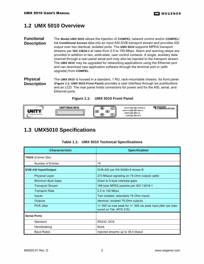
The UMX 5010 is housed in a standard, 1 RU, rack-mountable chassis. Its front panel (Figure 1.1: UMX 5010 Front Panel) provides a user interface through six pushbuttons and an LCD. The rear panel holds connectors for power and for the ASI, serial, and Ethernet ports.
Figure 1.1: UMX 5010 Front Panel
1.3 UMX5010 Specifications
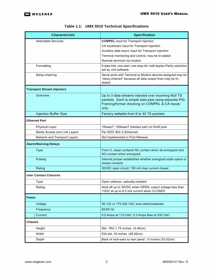
Table 1.1: UMX 5010 Technical Specifications
Characteristic Specification
TAGS (Carrier IDs)
Number of Entries 15
DVB ASI Input/Output DVB-ASI per EN 50083-9 Annex B
Physical Layer 270 Mbaud signaling on 75-Ohm coaxial cable
Minimum Byte Gaps Down to 0-byte interbyte gaps
Transport Stream 188-byte MPEG packets per ISO 13818-1
Transport Rate 2.5 to 100 Mbps
Inputs Two isolated, selectable 75-Ohm inputs
Outputs Identical, isolated 75-Ohm outputs
PCR Jitter +/- 500 ns max peak for +/- 300 ms peak input jitter (as mea-sured on Tek. MTS 215)
Serial Ports
Standard RS232, DCE
Handshaking None
Baud Rates Injected streams up to 38.4 kbaud
UMX 5010 USER’S MANUAL
www.wegener.com 3 800025-01 Rev. D
Selectable Services COMPEL input for Transport injection
CA keystream input for Transport injection
Auxiliary data async input for Transport injection
Terminal monitoring and control, may be tri-stated
Remote terminal via modem
Formatting 8 data bits, one start, one stop-bit, half-duplex.Parity selection set by unit software.
Daisy-chaining Serial ports with Terminal or Modem devices assigned may be “daisy-chained” because all data output lines may be tri-stated.
Transport Stream Injectors
Overview Up to 3 data streams injected over incoming Null TS packets. Each is simple data pipe using separate PID. Framing/format checking on COMPEL & CA inputs only.
Injection Buffer Size Factory settable from 8 to 32 TS packets
Ethernet Port
Physical Layer 10baseT, 100baseT (twisted pair) on RJ45 jack
Media Access and Link Layers Per IEEE 802.3 (Ethernet)
Network and Transport Layers Not implemented in First Release
Alarm/Warning Relays
Type Form C, wiper contacts NC contact when de-energized and NO contact when energized
Polarity Internal jumper establishes whether energized state opens or closes contacts
Rating 30VDC open circuit, 100 mA max current closed
User Contact Closures
Type Open collector, optically-isolated
Rating Hold off up to 30VDC when OPEN; output voltage less than 1VDC at up to 8.0 mA current when CLOSED.
Power
Voltage 90-132 or 175-264 VAC auto-detect/selected
Frequency 60/50 Hz
Current 0.5 Amps at 115 VAC; 0.3 Amps Max at 230 VAC
Chassis
Height Std. 1RU 1.75 inches (4.45cm)
Width EIA std. 19 inches (48.26cm)
Depth Back of rack-ears to rear panel: 13 inches (33.02cm)
Table 1.1: UMX 5010 Technical Specifications
Characteristic Specification
UMX 5010 USER’S MANUAL
800025-01 Rev. D 4 www.wegener.com
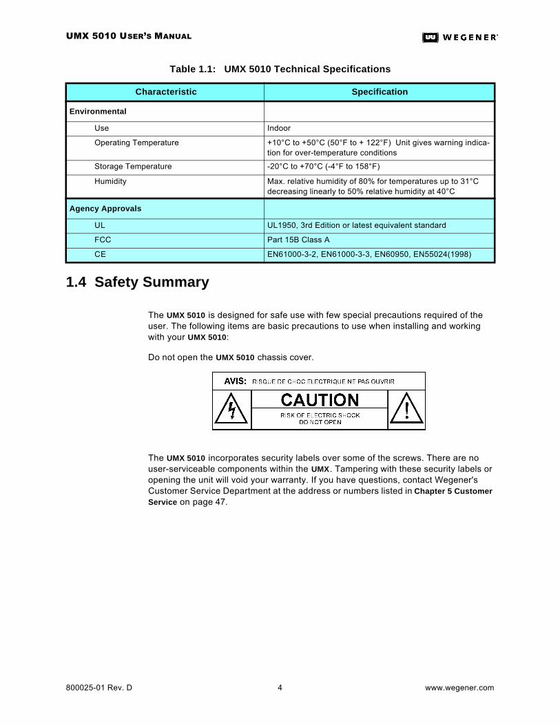
1.4 Safety Summary
The UMX 5010 is designed for safe use with few special precautions required of the user. The following items are basic precautions to use when installing and working with your UMX 5010:
Do not open the UMX 5010 chassis cover.
The UMX 5010 incorporates security labels over some of the screws. There are no user-serviceable components within the UMX. Tampering with these security labels or opening the unit will void your warranty. If you have questions, contact Wegener's Customer Service Department at the address or numbers listed in Chapter 5 Customer Service on page 47.
Environmental
Use Indoor
Operating Temperature +10°C to +50°C (50°F to + 122°F) Unit gives warning indica-tion for over-temperature conditions
Storage Temperature -20°C to +70°C (-4°F to 158°F)
Humidity Max. relative humidity of 80% for temperatures up to 31°C decreasing linearly to 50% relative humidity at 40°C
Agency Approvals
UL UL1950, 3rd Edition or latest equivalent standard
FCC Part 15B Class A
CE EN61000-3-2, EN61000-3-3, EN60950, EN55024(1998)
Table 1.1: UMX 5010 Technical Specifications
Characteristic Specification

UMX 5010 USER’S MANUAL
www.wegener.com 5 800025-01 Rev. D
CHAPTER 2 INSTALLATION
This chapter provides instructions on unpacking, mounting, and connecting your UMX 5010 as well as connector information including detailed pinouts.
2.1 Unpacking and InspectionCarefully unpack the unit and its ac power cord and inspect for obvious signs of physical damage that might have occurred during shipment. Any damage claims must be reported to the carrier immediately. Be sure to check the package contents carefully for important documents and materials.
NOTE: Please save the packing materials and original shipping containers in case you must later return the unit for repair. Packing these units in other containers in such a way that they are damaged will void your warranty.
2.2 Location and MountingThe UMX 5010 may be mounted in a standard 19-inch equipment rack or set up for desk-top operation. In either location, maintain a clean, dry environment for your UMX 5010.
FCC-Mandated Suppression of Radiated Emissions
If the Ethernet port has a cable connected to it, that cable MUST be properly shielded and grounded. This must be done to minimize RF emissions which could interfere with nearby equipment.
WARNING
This is a Class A product. In a domestic environment this product may cause radio interference for which the user may need to take mitigating action.
DANGER
To avoid damage to this and other equipment, or personal injury, the following items should be strictly observed.
Elevated Operating Ambient
When equipment is installed in a closed or multi-unit rack assembly, the operating ambient of the rack environment may be greater than the room ambient. Therefore, consideration should be given to the ambient air temperature within the rack, and not just inside the room, when deciding if the maximum recommended ambient operating temperature (TMRA) is being met.
Reduced Air Flow
Equipment should be installed such that airflow required for safe operation of the equip-ment is not compromised. The UnityMux may be arranged in a rack without empty spaces between units if heat rise is prevented by ensuring its side vents remain unblocked with adequate clearance around the vent holes.

UMX 5010 USER’S MANUAL
800025-01 Rev. D 6 www.wegener.com
Mechanical Loading
Mounting of the equipment in a rack should be such that a hazardous condition is not pro-duced by uneven loading. This unit is not very heavy, but total rack loading must be con-sidered. Also, do not rest any unsupported equipment on your UMX 5010.
Circuit Overloading
Consideration should be given to the connection of the equipment to the supply circuit and the effect that overloading of circuits could have on overcurrent protection and supply wir-ing. Ensure that the total rack or breaker power consumption does not exceed the limits of the AC branch circuit. Appropriate consideration of equipment ratings should be used when addressing this concern.
Reliable Earthing
Reliable earthing of rack-mounted equipment should be maintained. Particular attention should be given to supply connections other than direct connections to the branch circuit (use of power strips, chassis ground lugs, etc.).
Rack Mounting
The UMX 5010 is sized at a single RU and will fit an EIA-standard, 19-inch-wide equipment rack.
d. First install angle brackets or cross-supports capable of supporting both the unit and its connecting cables. Screw or bolt the supports securely to the equipment rack.
e. Place the UMX 5010 on its supports and use four anchor screws or bolts and nuts to secure the UMX 5010 front brackets to the rack.
WARNING
The front brackets must be secured to the rack. If front brackets are left unsecured, the unit may shift forward and fall from the rack during installation or operation. Failure to secure the front brackets may result in personal injury and/or damage to the equipment.
Desktop Installation
To set up the UMX 5010 in a desktop environment, place the UMX 5010 on a flat surface where it will not be subject to spills or impacts. Also route cables to the unit so that they will not be hit or pulled causing damage to the connectors or to the unit itself. Ensure a sufficient flow of cool air (See “Reduced Air Flow” on page 5.) so that the unit's operating ambient temperature range is not exceeded.
WARNING
Locate the UMX 5010 and its cables to avoid impacts, spills, and pulling cables and to ensure sufficient air flow. Failure to locate the UMX 5010 in a proper environment may result in damage to the equipment.

UMX 5010 USER’S MANUAL
www.wegener.com 7 800025-01 Rev. D
2.3 UMX 5010 ConnectionsFigure 2.1 shows the connector locations on the UMX 5010 rear panel.
Figure 2.1: UMX 5010 Rear-Panel Connector Locations
Table 2.1: , below, lists the UMX 5010 connectors, their types, and pinout information. See Rear-Panel LEDs on page 13 for descriptions of rear-panel indicators.
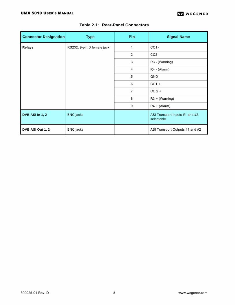
Table 2.1: Rear-Panel Connectors
Connector Designation Type Pin Signal Name
115/230 VAC Std IEC Receptacle AC line in
Ethernet RJ45 Jack 1 (on left as viewed from rear of unit)
TXDO +
2 TXDO -
3 RXDI +
4 Terminated 75 Ω / 1000 pF
5 Terminated 75 Ω / 1000 pF
6 RXDI -
7 Terminated 75 Ω / 1000 pF
8 Terminated 75 Ω / 1000 pF
COMPEL IN, CA IN, AUX/TERM ports
RS232, 9-pin D female jacks 1 DCD (internally pulled to +5V)
2 RxD (output)
3 TxD (input)
4 DTR (not connected)
5 GND
6 DSR (internally pulled to +5V)
7 RTS (not connected)
8 CTS (internally pulled to +5V)
9 RI (internally pulled to +5V, with weak current limiting)
UMX 5010 USER’S MANUAL
800025-01 Rev. D 8 www.wegener.com
Relays RS232, 9-pin D female jack 1 CC1 -
2 CC2 -
3 R3 - (Warning)
4 R4 - (Alarm)
5 GND
6 CC1 +
7 CC 2 +
8 R3 + (Warning)
9 R4 + (Alarm)
DVB ASI In 1, 2 BNC jacks ASI Transport Inputs #1 and #2, selectable
DVB ASI Out 1, 2 BNC jacks ASI Transport Outputs #1 and #2
Table 2.1: Rear-Panel Connectors
Connector Designation Type Pin Signal Name
UMX 5010 USER’S MANUAL
www.wegener.com 9 800025-01 Rev. D
CHAPTER 3 OPERATION
3.1 Operation Overview
Most routine UMX 5010 operations are performed over the Compel network or through a local or remote terminal. However, front-panel control is required for changing some key unit settings.
This chapter provides details about the front-panel controls and indicators, the serial ports, the alarm/warning system, and unit operation through the LCD menu screens.
3.2 Controls and Indicators
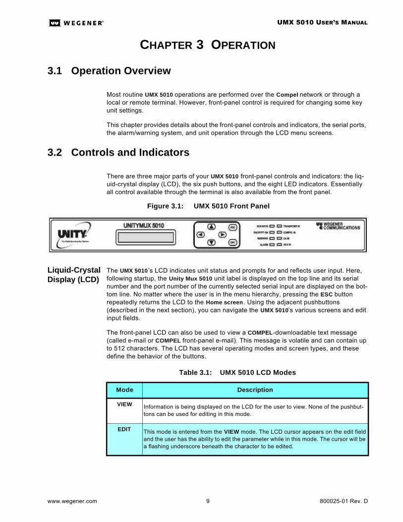
There are three major parts of your UMX 5010 front-panel controls and indicators: the liq-uid-crystal display (LCD), the six push buttons, and the eight LED indicators. Essentially all control available through the terminal is also available from the front panel.
Figure 3.1: UMX 5010 Front Panel
Liquid-Crystal Display (LCD)
The UMX 5010 ’s LCD indicates unit status and prompts for and reflects user input. Here, following startup, the Unity Mux 5010 unit label is displayed on the top line and its serial number and the port number of the currently selected serial input are displayed on the bot-tom line. No matter where the user is in the menu hierarchy, pressing the ESC button repeatedly returns the LCD to the Home screen. Using the adjacent pushbuttons (described in the next section), you can navigate the UMX 5010’s various screens and edit input fields.
The front-panel LCD can also be used to view a COMPEL-downloadable text message (called e-mail or COMPEL front-panel e-mail). This message is volatile and can contain up to 512 characters. The LCD has several operating modes and screen types, and these define the behavior of the buttons.
Table 3.1: UMX 5010 LCD Modes
Mode Description
VIEW Information is being displayed on the LCD for the user to view. None of the pushbut-tons can be used for editing in this mode.
EDIT This mode is entered from the VIEW mode. The LCD cursor appears on the edit field and the user has the ability to edit the parameter while in this mode. The cursor will be a flashing underscore beneath the character to be edited.
UMX 5010 USER’S MANUAL
800025-01 Rev. D 10 www.wegener.com
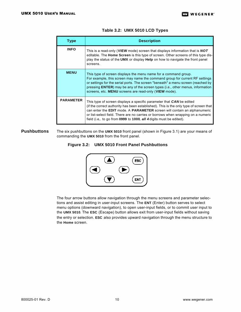
Pushbuttons The six pushbuttons on the UMX 5010 front panel (shown in Figure 3.1) are your means of commanding the UMX 5010 from the front panel.
Figure 3.2: UMX 5010 Front Panel Pushbuttons
The four arrow buttons allow navigation through the menu screens and parameter selec-tions and assist editing in user-input screens. The ENT (Enter) button serves to select menu options (downward navigation), to open user-input fields, or to commit user input to the UMX 5010. The ESC (Escape) button allows exit from user-input fields without saving the entry or selection. ESC also provides upward navigation through the menu structure to the Home screen.
Table 3.2: UMX 5010 LCD Types
Type Description
INFO This is a read-only (VIEW mode) screen that displays information that is NOT editable. The Home Screen is this type of screen. Other screens of this type dis-play the status of the UMX or display Help on how to navigate the front panel screens.
MENU This type of screen displays the menu name for a command group. For example, this screen may name the command group for current RF settings or settings for the serial ports. The screen "beneath" a menu screen (reached by pressing ENTER) may be any of the screen types (i.e., other menus, information screens, etc. MENU screens are read-only (VIEW mode).
PARAMETER This type of screen displays a specific parameter that CAN be edited (if the correct authority has been established). This is the only type of screen that can enter the EDIT mode. A PARAMETER screen will contain an alphanumeric or list-select field. There are no carries or borrows when wrapping on a numeric field (i.e,. to go from 0999 to 1000, all 4 digits must be edited).
UMX 5010 USER’S MANUAL
www.wegener.com 11 800025-01 Rev. D
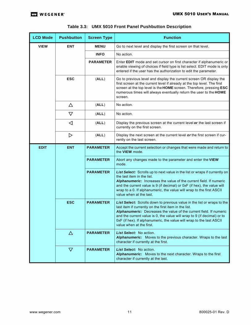
Table 3.3: UMX 5010 Front Panel Pushbutton Description
LCD Mode Pushbutton Screen Type Function
VIEW ENT MENU Go to next level and display the first screen on that level.
INFO No action.
PARAMETER Enter EDIT mode and set cursor on first character if alphanumeric or enable viewing of choices if field type is list select. EDIT mode is only entered if the user has the authorization to edit the parameter.
ESC (ALL) Go to previous level and display the current screen OR display the first screen at the current level if already at the top level. The first screen at the top level is the HOME screen. Therefore, pressing ESC numerous times will always eventually return the user to the HOME screen.
rr (ALL) No action.
ss (ALL) No action.
vv (ALL) Display the previous screen at the current level or the last screen if currently on the first screen.
ww (ALL) Display the next screen at the current level or the first screen if cur-rently on the last screen.
EDIT ENT PARAMETER Accept the current selection or changes that were made and return to the VIEW mode.
PARAMETER Abort any changes made to the parameter and enter the VIEW mode.
PARAMETER List Select: Scrolls up to next value in the list or wraps if currently on the last item in the list.Alphanumeric: Increases the value of the current field. If numeric and the current value is 9 (if decimal) or 0xF (if hex), the value will wrap to a 0. If alphanumeric, the value will wrap to the first ASCII value when at the last.
ESC PARAMETER List Select: Scrolls down to previous value in the list or wraps to the last item if currently on the first item in the list.Alphanumeric: Decreases the value of the current field. If numeric and the current value is 0, the value will wrap to 9 (if decimal) or to 0xF (if hex). If alphanumeric, the value will wrap to the last ASCII value when at the first.
rr PARAMETER List Select: No action.Alphanumeric: Moves to the previous character. Wraps to the last character if currently at the first.
ss PARAMETER List Select: No action.Alphanumeric: Moves to the next character. Wraps to the first character if currently at the last.
UMX 5010 USER’S MANUAL
800025-01 Rev. D 12 www.wegener.com
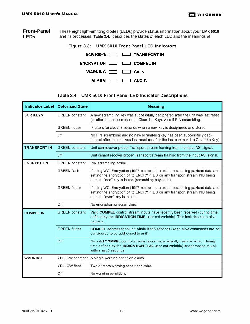
Front-Panel LEDs
These eight light-emitting diodes (LEDs) provide status information about your UMX 5010 and its processes. Table 3.4: describes the states of each LED and the meanings of
Figure 3.3: UMX 5010 Front Panel LED Indicators
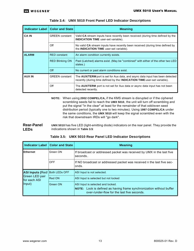
Table 3.4: UMX 5010 Front Panel LED Indicator Descriptions
Indicator Label Color and State Meaning
SCR KEYS GREEN constant A new scrambling key was successfully deciphered after the unit was last reset (or after the last command to Clear the Key). Also if PIN scrambling.
GREEN flutter Flutters for about 2 seconds when a new key is deciphered and stored.
Off No PIN scrambling and no new scrambling key has been successfully deci-phered after the unit was last reset (or after the last command to Clear the Key).
TRANSPORT IN GREEN constant Unit can recover proper Transport stream framing from the input ASI signal.
Off Unit cannot recover proper Transport stream framing from the input ASI signal.
ENCRYPT ON GREEN constant PIN scrambling active.
GREEN flash If using WCI Encryption (1997 version), the unit is scrambling payload data and setting the encryption bit to ENCRYPTED on any transport stream PID being output - “odd” key is in use (scrambling payloads).
GREEN flutter If using WCI Encryption (1997 version), the unit is scrambling payload data and setting the encryption bit to ENCRYPTED on any transport stream PID being output - “even” key is in use.
Off No encryption or scrambling.
COMPEL IN GREEN constant Valid COMPEL control stream inputs have recently been received (during time defined by the INDICATION TIME user-set variable). This includes keep-alive packets.
GREEN flutter COMPEL addressed to unit within last 5 seconds (keep-alive commands are not considered to be addressed to unit).
Off No valid COMPEL control stream inputs have recently been received (during time defined by the INDICATION TIME user-set variable) or addressed to unit within last 5 seconds.
WARNING YELLOW constant A single warning condition exists.
YELLOW flash Two or more warning conditions exist.
Off No warning conditions.
UMX 5010 USER’S MANUAL
www.wegener.com 13 800025-01 Rev. D
NOTE: When using 2002 COMPEL/CA, if the KMS stream is disrupted or if the ciphered scrambling seeds fail to reach the UMX 5010, the unit will turn off scrambling and put the signal "in the clear" at least for the remainder of that odd/even seed distribution period (typically one to two minutes). Using 1997 COMPEL/CA under the same conditions, the UMX 5010 will keep the signal scrambled even with the risk that downstream IRDs will "go dark".
Rear-Panel LEDs
UMX 5010 has five LED (light-emitting diode) indicators on the rear panel. They provide the indications shown in Table 3.5:
CA IN GREEN constant Valid CA stream inputs have recently been received (during time defined by the INDICATION TIME user-set variable).
Off No valid CA stream inputs have recently been received (during time defined by the INDICATION TIME user-set variable).
ALARM RED constant An alarm condition currently exists.
RED Blinking ON Past (Latched) alarms exist. (May be "combined" with either of the other two LED states.)
Off No current or past alarm conditions exist.
AUX IN GREEN constant The AUX/TERM port is set for Aux data, and async data input has been detected recently (during time defined by the INDICATION TIME user-set variable).
Off The AUX/TERM port is not set for Aux data or async data input has not been detected recently.
Table 3.4: UMX 5010 Front Panel LED Indicator Descriptions
Indicator Label Color and State Meaning
Table 3.5: UMX 5010 Rear Panel LED Indicator Descriptions
Indicator Label Color and State Meaning
Ethernet Green ON If broadcast or addressed packet was received by UMX in the last five seconds..
OFF If NO broadcast or addressed packet was received n the last five sec-onds.
ASI Inputs (Red/Green LED pair for each ASI Input)
Both LEDs OFF ASI Input is not selected.
Red ON ASI Input is selected but not locked
Green ON ASI Input is selected and locked.
NOTE: Lock is defined as having frame synchronization without buffer over-/under-flow for the last five seconds.

UMX 5010 USER’S MANUAL
800025-01 Rev. D 14 www.wegener.com
Device Port Assignments
The UMX 5010 has three external serial ports. A device must be assigned once to each serial port, but no device may be assigned more than once. In addition, Terminal and Modem devices may not be assigned at the same time. Device Port Assignment and Device Configuration (below) may be controlled only from the unit front panel, and the net-work may disable this capability. The possible devices are:
• Terminal
• Modem (“modem” being remote terminal via modem)
• Auxiliary Data
• CA
• COMPEL
Device Configuration
When a serial port configuration command is received, the specified configuration is immediately stored for the specified device (e.g., for the Terminal device). If a serial port is currently assigned to another device, then its output buffer is immediately flushed and the port re-configured. Communication is fixed at 1 start, 1 stop, and 8 data bits, with no hard-ware handshaking. No provision for software handshaking is made in this Release. The serial port’s behavior for each of its device types is described in Table 3.6:
Device Handling
Terminal I/O
The Terminal device is used for command and control of the UMX 5010. This I/O is a basic VT100-like emulation. All I/O is prompted by user-input text strings terminated in carriage-returns. The terminal, whether local or (via modem) remote, should be set to local echo ON because the unit only echoes a carriage-return/linefeed and then displays a > prompt after entry of a command line terminated in a carriage-return.
Daisy Chain Communication
The UMX 5010 supports “daisy-chaining” of terminal control. This involves sharing of a serial bus between two or more UMXs. The serial bus consists of both the TX and RX serial port lines wired in parallel, connected to a serial port on all the UMXs and the termi-nal communication device (either a local terminal or modem).
Certain operating states are defined for the UMXs using this daisy-chain capability. These states are Talker, Idle, and Waiting for password. Units will transition from either Talker or Idle over to Waiting for password when a wakeup “hotkey” is received from the user (see Daisy Chain Terminal Communication on page 39). Then, after the two-digit ID passcode is
Table 3.6: UMX 5010 Serial Port Device Configurations
Device Serial Port Behavior (Italics are Programmable, Bold are Fixed)
Terminal Configured to 19.2k, N, 8, 1. The unit responds to the terminal commands as described in Appendix A.
Modem Configured to B, P, 8, 1. The unit responds to the terminal commands, as described in Appendix A.
Aux Data Configured to B, P, 8, 1. This is an input only.
CA Configured to B, P, 8, 1. This is an input only.
COMPEL Configured to B, P, 8, 1. This is an input only.
The legal values for B are: 1200, 2400, 4800, 9600, 19.2k, or 38.4 kBaud.For Aux Data only, 115.2 kBaud is also allowed.The legal values for P are: O, E, or N for Odd, Even, or No parity.
UMX 5010 USER’S MANUAL
www.wegener.com 15 800025-01 Rev. D
received, any unit matching that passcode proceeds to Talker state (and switches its serial output to Active), while all others proceed to Idle. While in an Idle state, a unit’s serial port, which is allocated as a Terminal or Modem device has an electrically isolated (tri-state) output and responds only to a hotkey input. When in the Talker state, the unit issues prompts and responds to commands normally.
NOTE: These states are held only in volatile memory, and a unit reverts to the Idle state during and after a unit reset Modem I/O.
The unit ID may be assigned by the user and is a non-volatile setting. Assigning a unit ID of 00 effectively disables this daisy-chain capability. This leaves an UMX continuously in the normal Talker state, even through unit resets.
Modem I/O
The Modem device operates in a similar manner to the Terminal device. Where the Termi-nal device was limited to a specific configuration, the Modem device may be set to one of several. The Modem device does not use special handshaking or special control charac-ters, and only supports auto-answer modems. In fact, in the standard interface, the UMX would not know if a local or remote (via modem) terminal were actually attached to the port.
To access the modem command interface, the serial-port device must first be set to Modem (using only the front-panel control interface). The discussion above on emulation and echoing would then apply. The user would send the unit a carriage return and then the unit would return a prompt to enter the password. If the correct password is entered, then modem access is enabled. Upon enabling modem access, the UMX will output a wel-come banner. After that, I/O is indistinguishable from normal terminal access, with the same restriction on local user access as set by the Network.
Modem access is disabled when:
1. A new serial-port device is selected,
2. There is no user input for 10 minutes,
3. The OH command is received, or
4. The unit is reset.
Aux Data
The Aux Data device is defined to allow for async data streams to be carried within the transport stream and their raw payload output on an IRD serial port. The PID of these streams may or may not be assigned to a program number within a PMT. To recover the data, the IRD need only be given the PID and baud rate. The range of legal PIDs is estab-lished by the ISO 13818 standard as 20 to 1FFE (hex). This may be performed either by COMPEL command or by the local user (if local control is enabled).
CA Input
This device is defined to allow for input of the Conditional Access key stream (legacy term KMS stream). There is no output.
COMPEL
This device is defined to allow for input of the COMPEL control stream. There is no output.

UMX 5010 USER’S MANUAL
800025-01 Rev. D 16 www.wegener.com
3.3 Alarm/Warning System
The alarm and warning system is intended to provide indications to local users of a critical failure or imminent failure. The indication persists only as long as the causative condition, except where otherwise noted. See Alarm Conditions below for actual indications.
Alarm Conditions
Generally, an Alarm condition exists if the unit is unable (or presumed to be unable) to inject COMPEL or CA into an input transport stream. The following list defines all alarms during normal operation. They are listed in the order of priority by which they will be reported on the front-panel Home screen.
1. No transport stream sync on current ASI input
2. Failure of various outputs if allowed by programmable control mask. (See Maskable Alarm and Warning Conditions on page 16.)
During an initialization failure, the alarm relay is de-energized (Alarm state) and the alarm LED is ON.
Warning Conditions
Generally, the unit presents warnings when an alarm condition may be imminent from unit stress or poor signal conditions. The following list defines all warnings during normal oper-ation. They are listed in order of priority by which they will be reported on the front-panel Home screen.
1. CA secure microprocessor run-time failure or SN mismatch (if applicable)
2. Multiple assignment of an inected PID.
3. Unit reverted to backup application software because of self-test failure of requested application (continues until user keypress).
4. Failure of various outputs if allowed by programmable control mask. (See-Maskable Alarm and Warning Conditions below.)
5. Unit overheating.
Maskable Alarm and Warning Conditions
All the following may be unit alarms, unit warnings, or no indication, as programmed. They are listed in the order of priority by which they will be reported on the front-panel Home screen. Defaults are shown in braces .
1. No COMPEL stream input. Default: Warn on failure
2. Serial data injection buffer overflow. Default: Alarm on failure.
3. Incoming COMPEL Header does not match Default: Warn on failure unit’s COMPEL Header settings.
4. Serial data injection buffer >75%. Default: Warn on failure
5. No addressed COMPEL received. Default: No Indication
6. No CA stream input. Default: No Indication
7. No Aux data input, if port is designated for Aux data.Default: Warn on failure
8. No Scrambling keys deciphered. Default: No Indication
9. Encryption OFF. Default: No Indication
10. No scrambling key. Default: No Indication
11. No tags sites assigned. Default: Warn on failure
12. No ID tags transmitted. Default: Warn on failure
13. Other option card output failures. Default: No indication
UMX 5010 USER’S MANUAL
www.wegener.com 17 800025-01 Rev. D
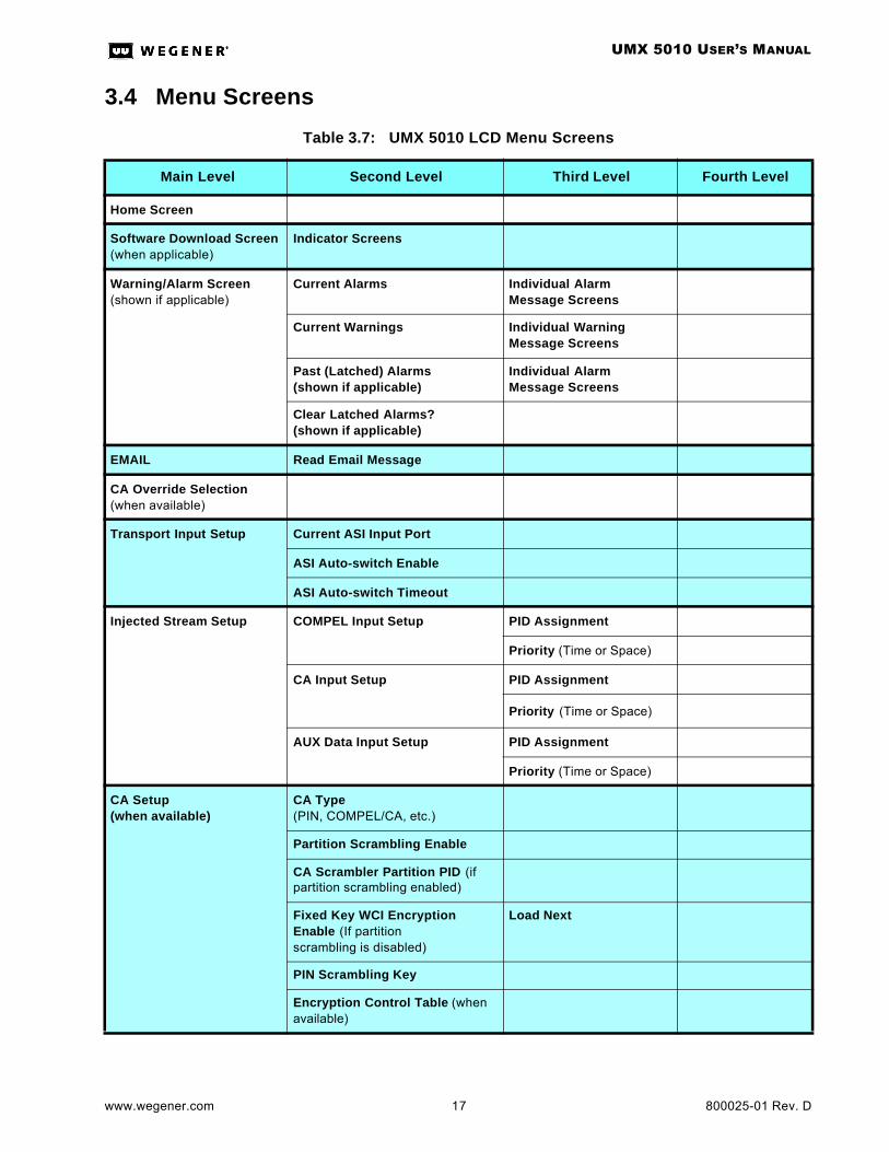
3.4 Menu Screens
Table 3.7: UMX 5010 LCD Menu Screens
Main Level Second Level Third Level Fourth Level
Home Screen
Software Download Screen(when applicable)
Indicator Screens
Warning/Alarm Screen(shown if applicable)
Current Alarms Individual Alarm Message Screens
Current Warnings Individual Warning Message Screens
Past (Latched) Alarms(shown if applicable)
Individual Alarm Message Screens
Clear Latched Alarms?(shown if applicable)
EMAIL Read Email Message
CA Override Selection(when available)
Transport Input Setup Current ASI Input Port
ASI Auto-switch Enable
ASI Auto-switch Timeout
Injected Stream Setup COMPEL Input Setup PID Assignment
Priority (Time or Space)
CA Input Setup PID Assignment
Priority (Time or Space)
AUX Data Input Setup PID Assignment
Priority (Time or Space)
CA Setup(when available)
CA Type (PIN, COMPEL/CA, etc.)
Partition Scrambling Enable
CA Scrambler Partition PID (if partition scrambling enabled)
Fixed Key WCI Encryption Enable (If partition scrambling is disabled)
Load Next
PIN Scrambling Key
Encryption Control Table (when available)
UMX 5010 USER’S MANUAL
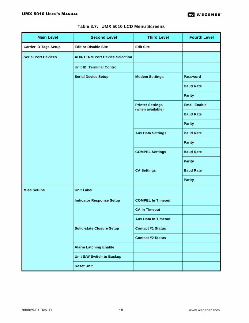
800025-01 Rev. D 18 www.wegener.com
Carrier ID Tags Setup Edit or Disable Site Edit Site
Serial Port Devices AUX/TERM Port Device Selection
Unit ID, Terminal Control
Serial Device Setup Modem Settings Password
Baud Rate
Parity
Printer Settings(when available)
Email Enable
Baud Rate
Parity
Aux Data Settings Baud Rate
Parity
COMPEL Settings Baud Rate
Parity
CA Settings Baud Rate
Parity
Misc Setups Unit Label
Indicator Response Setup COMPEL In Timeout
CA In Timeout
Aux Data In Timeout
Solid-state Closure Setup Contact #1 Status
Contact #2 Status
Alarm Latching Enable
Unit S/W Switch to Backup
Reset Unit
Table 3.7: UMX 5010 LCD Menu Screens
Main Level Second Level Third Level Fourth Level

UMX 5010 USER’S MANUAL
www.wegener.com 19 800025-01 Rev. D
Unit Status ASI Transport Current
Lost-lock Events
COMPEL Data Stream Current
Number/Time of lost input events
CA Data Stream Current
Number/Time of lost input events
AUX Data Stream(only shown when AUX device is assigned to AUX/TERM port)
Current
Number/Time of lost input events
Serial Data Injection Buffer Current
Buffer Overflow
Transport Stream Status Estimated Data Rate
NULL Packet Bandwidth
NULL Packet Percentage Used
Time Since Log Last Cleared
Clear Logs
Network Control Status(when available)
Delaying Log
Serial Number, COMPEL lock sta-tus, COMPEL-required setting
Local Control Enable status, Net-work Protection mode
Time since Last Header, Time since Last addressed Header
Total History, Total processed COMPEL packets
Packets with invalid Header, Packets with invalid Checksum
Packets with Invalid length, Buffer overflow
Packets with syntax errors
Table 3.7: UMX 5010 LCD Menu Screens
Main Level Second Level Third Level Fourth Level
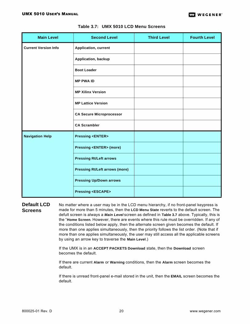
UMX 5010 USER’S MANUAL
800025-01 Rev. D 20 www.wegener.com
Default LCD Screens
No matter where a user may be in the LCD menu hierarchy, if no front-panel keypress is made for more than 5 minutes, then the LCD Menu State reverts to the default screen. The defult screen is always a Main Level screen as defined in Table 3.7 above. Typically, this is the “Home Screen. However, there are events where this rule must be overridden. If any of the conditions listed below apply, then the alternate screen given becomes the default. If more than one applies simultaneously, then the priority follows the list order. (Note that if more than one applies simultaneously, the user may still access all the applicable screens by using an arrow key to traverse the Main Level.)
If the UMX is in an ACCEPT PACKETS Download state, then the Download screen becomes the default.
If there are current Alarm or Warning conditions, then the Alarm screen becomes the default.
If there is unread front-panel e-mail stored in the unit, then the EMAIL screen becomes the default.
Current Version Info Application, current
Application, backup
Boot Loader
MP PWA ID
MP Xilinx Version
MP Lattice Version
CA Secure Microprocessor
CA Scrambler
Navigation Help Pressing <ENTER>
Pressing <ENTER> (more)
Pressing Rt/Left arrows
Pressing Rt/Left arrows (more)
Pressing Up/Down arrows
Pressing <ESCAPE>
Table 3.7: UMX 5010 LCD Menu Screens
Main Level Second Level Third Level Fourth Level
UMX 5010 USER’S MANUAL
www.wegener.com 21 800025-01 Rev. D
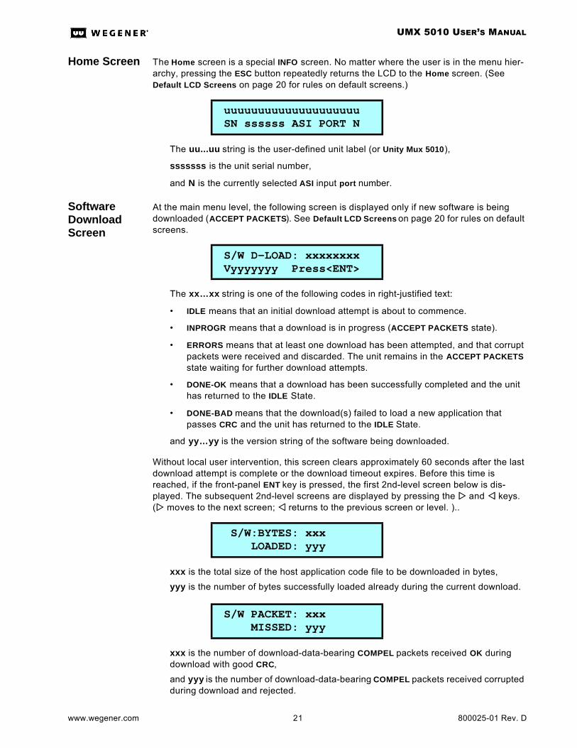
Home Screen The Home screen is a special INFO screen. No matter where the user is in the menu hier-archy, pressing the ESC button repeatedly returns the LCD to the Home screen. (See Default LCD Screens on page 20 for rules on default screens.)
The uu...uu string is the user-defined unit label (or Unity Mux 5010),
sssssss is the unit serial number,
and N is the currently selected ASI input port number.
Software Download Screen
At the main menu level, the following screen is displayed only if new software is being downloaded (ACCEPT PACKETS). See Default LCD Screens on page 20 for rules on default screens.
The xx…xx string is one of the following codes in right-justified text:
• IDLE means that an initial download attempt is about to commence.
• INPROGR means that a download is in progress (ACCEPT PACKETS state).
• ERRORS means that at least one download has been attempted, and that corrupt packets were received and discarded. The unit remains in the ACCEPT PACKETS state waiting for further download attempts.
• DONE-OK means that a download has been successfully completed and the unit has returned to the IDLE State.
• DONE-BAD means that the download(s) failed to load a new application that passes CRC and the unit has returned to the IDLE State.
and yy…yy is the version string of the software being downloaded.
Without local user intervention, this screen clears approximately 60 seconds after the last download attempt is complete or the download timeout expires. Before this time is reached, if the front-panel ENT key is pressed, the first 2nd-level screen below is dis-played. The subsequent 2nd-level screens are displayed by pressing the ww and vv keys. (ww moves to the next screen; vv returns to the previous screen or level. )..
xxx is the total size of the host application code file to be downloaded in bytes,
yyy is the number of bytes successfully loaded already during the current download.
xxx is the number of download-data-bearing COMPEL packets received OK during download with good CRC,
and yyy is the number of download-data-bearing COMPEL packets received corrupted during download and rejected.
uuuuuuuuuuuuuuuuuuuu SN ssssss ASI PORT N
S/W D-LOAD: xxxxxxxx Vyyyyyyy Press<ENT>
S/W:BYTES: xxx LOADED: yyy
S/W PACKET: xxx MISSED: yyy
UMX 5010 USER’S MANUAL
800025-01 Rev. D 22 www.wegener.com
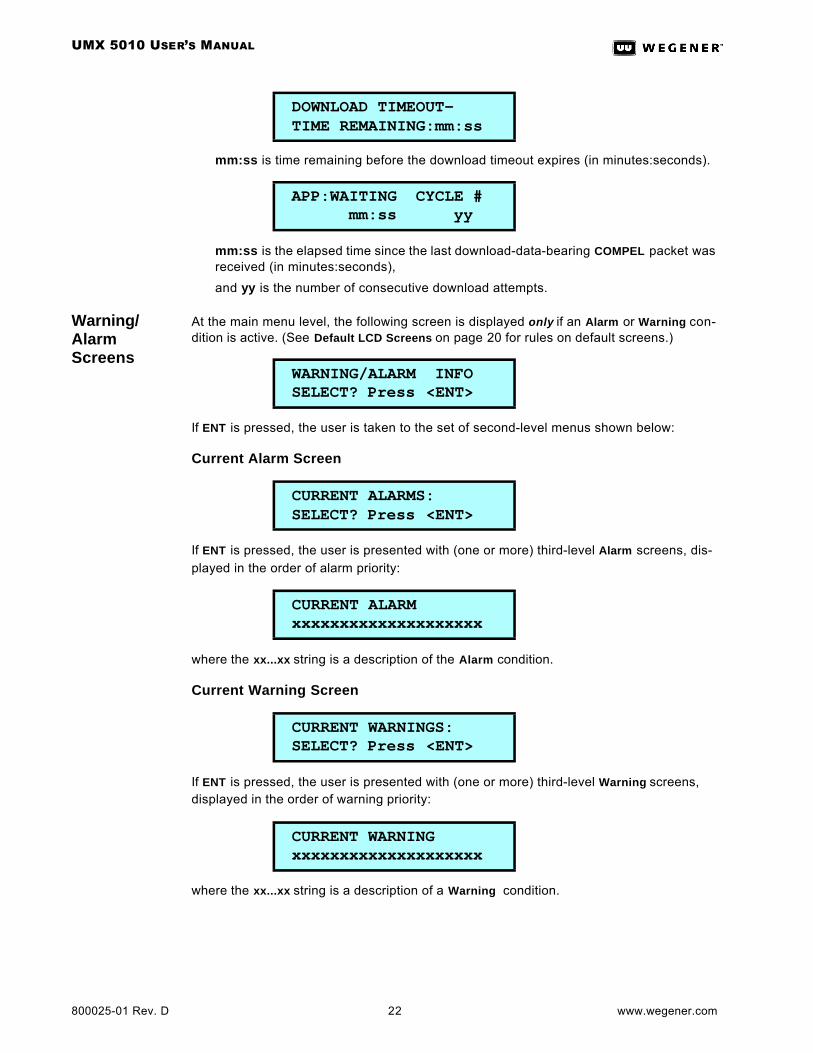
mm:ss is time remaining before the download timeout expires (in minutes:seconds).
mm:ss is the elapsed time since the last download-data-bearing COMPEL packet was received (in minutes:seconds),
and yy is the number of consecutive download attempts.
Warning/Alarm Screens
At the main menu level, the following screen is displayed only if an Alarm or Warning con-dition is active. (See Default LCD Screens on page 20 for rules on default screens.)
If ENT is pressed, the user is taken to the set of second-level menus shown below:
Current Alarm Screen
If ENT is pressed, the user is presented with (one or more) third-level Alarm screens, dis-played in the order of alarm priority:
where the xx...xx string is a description of the Alarm condition.
Current Warning Screen
If ENT is pressed, the user is presented with (one or more) third-level Warning screens, displayed in the order of warning priority:
where the xx...xx string is a description of a Warning condition.
DOWNLOAD TIMEOUT- TIME REMAINING:mm:ss
APP:WAITING CYCLE # mm:ss yy
WARNING/ALARM INFO SELECT? Press <ENT>
CURRENT ALARMS: SELECT? Press <ENT>
CURRENT ALARM xxxxxxxxxxxxxxxxxxxx
CURRENT WARNINGS: SELECT? Press <ENT>
CURRENT WARNING xxxxxxxxxxxxxxxxxxxx
UMX 5010 USER’S MANUAL
www.wegener.com 23 800025-01 Rev. D
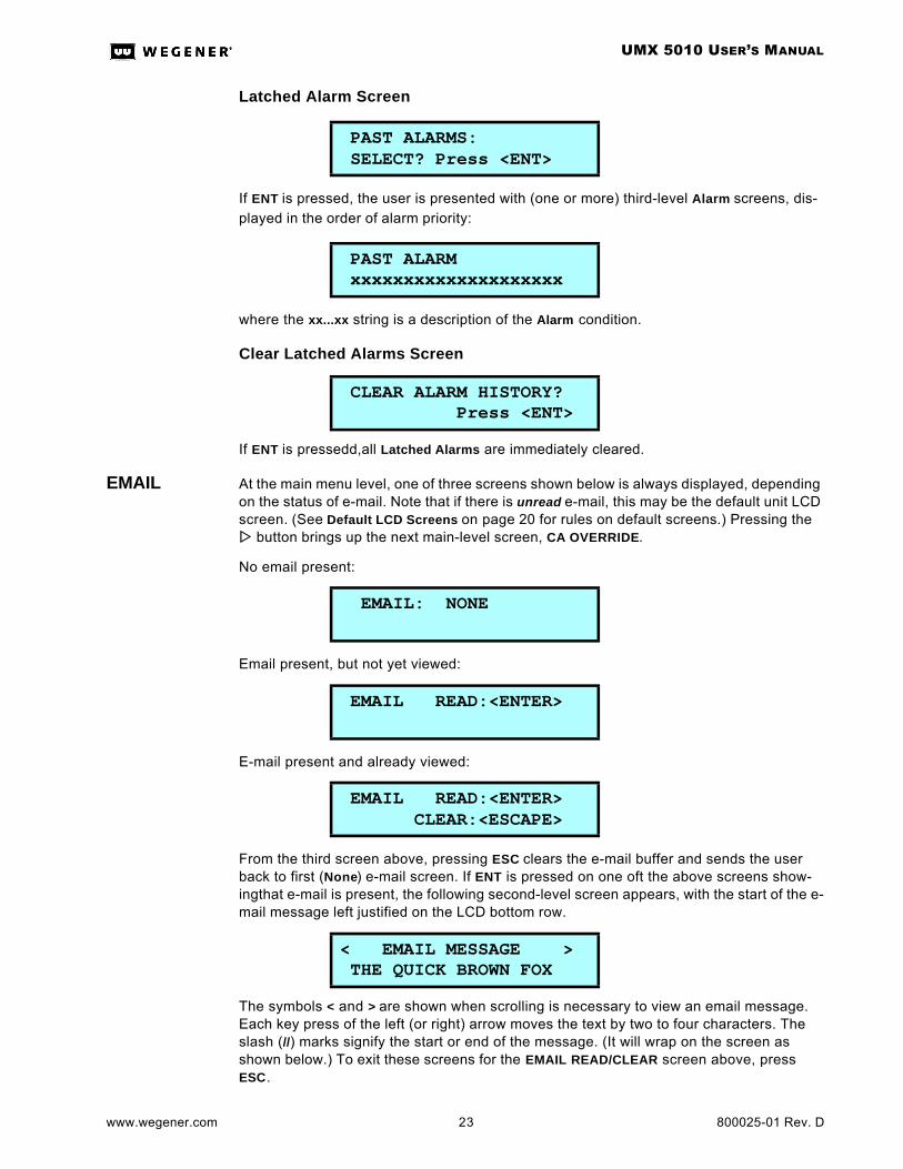
Latched Alarm Screen
If ENT is pressed, the user is presented with (one or more) third-level Alarm screens, dis-played in the order of alarm priority:
where the xx...xx string is a description of the Alarm condition.
Clear Latched Alarms Screen
If ENT is pressedd,all Latched Alarms are immediately cleared.
EMAIL At the main menu level, one of three screens shown below is always displayed, depending on the status of e-mail. Note that if there is unread e-mail, this may be the default unit LCD screen. (See Default LCD Screens on page 20 for rules on default screens.) Pressing the ww button brings up the next main-level screen, CA OVERRIDE.
No email present:
Email present, but not yet viewed:
E-mail present and already viewed:
From the third screen above, pressing ESC clears the e-mail buffer and sends the user back to first (None) e-mail screen. If ENT is pressed on one oft the above screens show-ingthat e-mail is present, the following second-level screen appears, with the start of the e-mail message left justified on the LCD bottom row.
The symbols < and > are shown when scrolling is necessary to view an email message. Each key press of the left (or right) arrow moves the text by two to four characters. The slash (//) marks signify the start or end of the message. (It will wrap on the screen as shown below.) To exit these screens for the EMAIL READ/CLEAR screen above, press ESC.
PAST ALARMS: SELECT? Press <ENT>
PAST ALARM xxxxxxxxxxxxxxxxxxxx
CLEAR ALARM HISTORY? Press <ENT>
EMAIL: NONE
EMAIL READ:<ENTER>
EMAIL READ:<ENTER> CLEAR:<ESCAPE>
< EMAIL MESSAGE > THE QUICK BROWN FOX

UMX 5010 USER’S MANUAL
800025-01 Rev. D 24 www.wegener.com
.
CA Override NOTE: This screen is only shown when WCI Encryption is installed:
Where xx…xx may be either:
CLEAR (forcing encryption OFF at all times) or
EXT CNTL (under control of the external COMPEL CA system).
Pressing the ww button brings up the next main-level screen, TRANSPORT INPUT.
Transport Input Setup
Pressing ENT brings up the second-level screens under Transport Input Setup shown below. (Pressing the ww button brings up the next main-level screen, INJECTED STREAM INPUT.)
Where x is either 1 or 2 to designate the active ASI input port.
Where xx…xx is either ENABLE or DISABLE. ENABLE forces the unit to automatically select the backup ASI input if a transport stream is not detected at the currently selected primary port.
Where mm:ss is the specified length of the timeout in minutes:seconds. After loss of transport stream is detected on the current primary port, the backup port will become the new current primary port after the specified timeout has expired.
< EMAIL MESSAGE > E LAZY DOG//THE QUIC
CA OVERRIDE SELECTION: xxxxxxx
TRANSPORT INPUT SETUP Press <ENTER>
CURRENT ASI INPUT PORT: x
ASI INPUT PORT AUTO-SWITCH: xxxxxxx
ASI AUTO-SWITCH TIMEOUT: mm:ss

UMX 5010 USER’S MANUAL
www.wegener.com 25 800025-01 Rev. D
Injected Stream Setup
Pressing ENT brings up the second-level screens under INJECTED STREAM INPUT shown below. (Pressing the ww button brings up the next main-level screen, CONDITIONAL ACCESS SETUP, which is available only when WCI Encryption is installed. If that screen is not installed, it moves to the next main-level screen, CARRIER ID TAGS SETUP.)
COMPEL Input
Pressing ENT brings up the third-level screens under COMPEL Input.(Pressing the ww but-ton brings up the next second-level screen, CA INPUT.).
Where xxxx is the PID to be used for the COMPEL Control stream.
Where xx…xx is either LATENCY or BANDWIDTH.
CA Input
Pressing ENT brings up the third-level screens under CA INPUT. (Pressing the ww button brings up the next second-level screen, AUX DATA INPUT.)
Where xxxx is the PID to be used for the CA Control stream.
Where xx…xx is either LATENCY or BANDWIDTH.
INJECTED STREAM SETUP Press <ENTER>
COMPEL INPUTSETUP Press <ENTER>
PID ASSIGNMENT (HEX) xxxx
PRIORITY xxxxxxxxx
COND. ACCESS INPUT SETUP Press <ENTER>
PID ASSIGNMENT (HEX) xxxx
PRIORITY: xxxxxxxxx
UMX 5010 USER’S MANUAL
800025-01 Rev. D 26 www.wegener.com
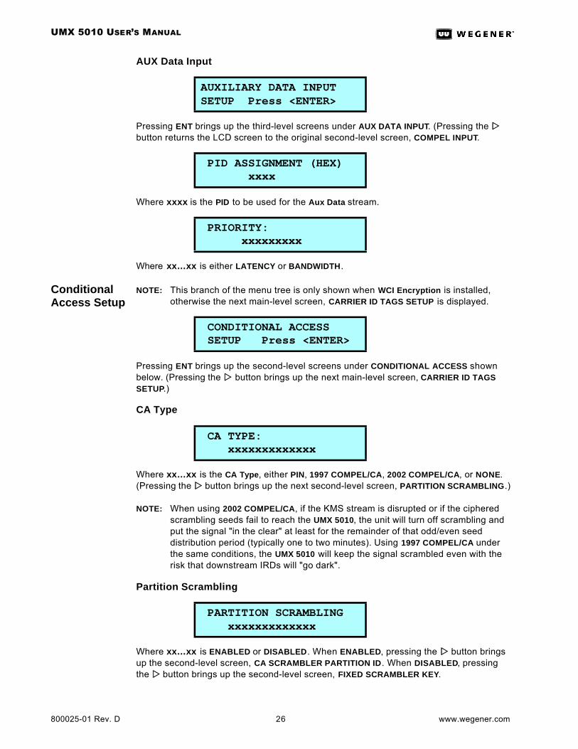
AUX Data Input
Pressing ENT brings up the third-level screens under AUX DATA INPUT. (Pressing the ww button returns the LCD screen to the original second-level screen, COMPEL INPUT.
Where xxxx is the PID to be used for the Aux Data stream.
Where xx…xx is either LATENCY or BANDWIDTH.
Conditional Access Setup
NOTE: This branch of the menu tree is only shown when WCI Encryption is installed, otherwise the next main-level screen, CARRIER ID TAGS SETUP is displayed.
Pressing ENT brings up the second-level screens under CONDITIONAL ACCESS shown below. (Pressing the ww button brings up the next main-level screen, CARRIER ID TAGS SETUP.)
CA Type
Where xx…xx is the CA Type, either PIN, 1997 COMPEL/CA, 2002 COMPEL/CA, or NONE. (Pressing the ww button brings up the next second-level screen, PARTITION SCRAMBLING.)
NOTE: When using 2002 COMPEL/CA, if the KMS stream is disrupted or if the ciphered scrambling seeds fail to reach the UMX 5010, the unit will turn off scrambling and put the signal "in the clear" at least for the remainder of that odd/even seed distribution period (typically one to two minutes). Using 1997 COMPEL/CA under the same conditions, the UMX 5010 will keep the signal scrambled even with the risk that downstream IRDs will "go dark".
Partition Scrambling
Where xx…xx is ENABLED or DISABLED. When ENABLED, pressing the ww button brings up the second-level screen, CA SCRAMBLER PARTITION ID. When DISABLED, pressing the ww button brings up the second-level screen, FIXED SCRAMBLER KEY.
AUXILIARY DATA INPUTSETUP Press <ENTER>
PID ASSIGNMENT (HEX) xxxx
PRIORITY: xxxxxxxxx
CONDITIONAL ACCESS SETUP Press <ENTER>
CA TYPE: xxxxxxxxxxxxx
PARTITION SCRAMBLING xxxxxxxxxxxxx
UMX 5010 USER’S MANUAL
www.wegener.com 27 800025-01 Rev. D
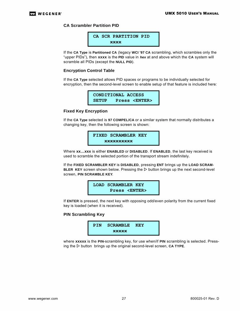
CA Scrambler Partition PID
If the CA Type is Partitioned CA (legacy WCI ’97 CA scrambling, which scrambles only the “upper PIDs”), then xxxx is the PID value in hex at and above which the CA system will scramble all PIDs (except the NULL PID).
Encryption Control Table
If the CA Type selected allows PID spaces or programs to be individually selected for encryption, then the second-level screen to enable setup of that feature is included here:
Fixed Key Encryption
If the CA Type selected is 97 COMPEL/CA or a similar system that normally distributes a changing key, then the following screen is shown:
Where xx…xxx is either ENABLED or DISABLED. If ENABLED, the last key received is used to scramble the selected portion of the transport stream indefinitely.
If the FIXED SCRAMBLER KEY is DISABLED, pressing ENT brings up the LOAD SCRAM-BLER KEY screen shown below. Pressing the ww button brings up the next second-level screen, PIN SCRAMBLE KEY.
If ENTER is pressed, the next key with opposing odd/even polarity from the current fixed key is loaded (when it is received).
PIN Scrambling Key
where xxxxx is the PIN-scrambling key, for use when/if PIN scrambling is selected. Press-ing the ww button brings up the original second-level screen, CA TYPE.
CA SCR PARTITION PID xxxx
CONDITIONAL ACCESS SETUP Press <ENTER>
FIXED SCRAMBLER KEY xxxxxxxxxx
LOAD SCRAMBLER KEY Press <ENTER>
PIN SCRAMBLE KEY xxxxx
UMX 5010 USER’S MANUAL
800025-01 Rev. D 28 www.wegener.com
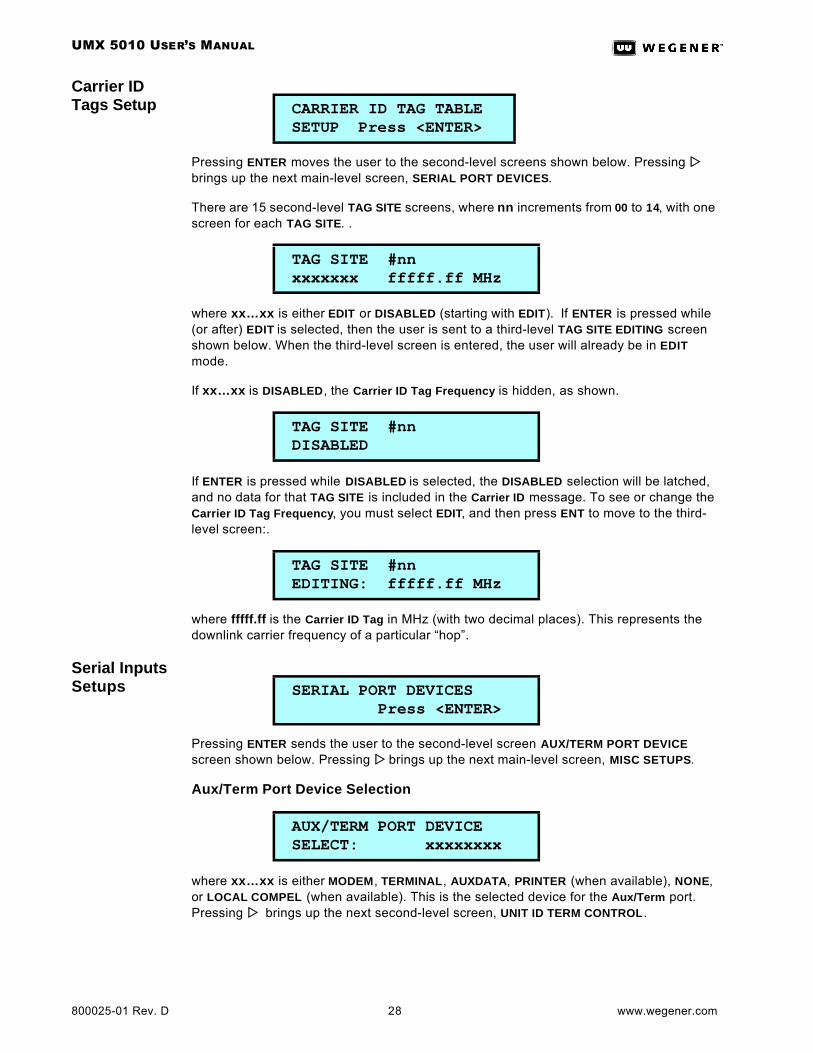
Carrier ID Tags Setup
Pressing ENTER moves the user to the second-level screens shown below. Pressing ww brings up the next main-level screen, SERIAL PORT DEVICES.
There are 15 second-level TAG SITE screens, where nn increments from 00 to 14, with one screen for each TAG SITE. .
where xx…xx is either EDIT or DISABLED (starting with EDIT). If ENTER is pressed while (or after) EDIT is selected, then the user is sent to a third-level TAG SITE EDITING screen shown below. When the third-level screen is entered, the user will already be in EDIT mode.
If xx…xx is DISABLED, the Carrier ID Tag Frequency is hidden, as shown.
If ENTER is pressed while DISABLED is selected, the DISABLED selection will be latched, and no data for that TAG SITE is included in the Carrier ID message. To see or change the Carrier ID Tag Frequency, you must select EDIT, and then press ENT to move to the third-level screen:.
where fffff.ff is the Carrier ID Tag in MHz (with two decimal places). This represents the downlink carrier frequency of a particular “hop”.
Serial Inputs Setups
Pressing ENTER sends the user to the second-level screen AUX/TERM PORT DEVICE screen shown below. Pressing ww brings up the next main-level screen, MISC SETUPS.
Aux/Term Port Device Selection
where xx…xx is either MODEM, TERMINAL, AUXDATA, PRINTER (when available), NONE, or LOCAL COMPEL (when available). This is the selected device for the Aux/Term port. Pressing ww brings up the next second-level screen, UNIT ID TERM CONTROL.
CARRIER ID TAG TABLE SETUP Press <ENTER>
TAG SITE #nn xxxxxxx fffff.ff MHz
TAG SITE #nn DISABLED
TAG SITE #nn EDITING: fffff.ff MHz
SERIAL PORT DEVICES Press <ENTER>
AUX/TERM PORT DEVICE SELECT: xxxxxxxx
UMX 5010 USER’S MANUAL
www.wegener.com 29 800025-01 Rev. D
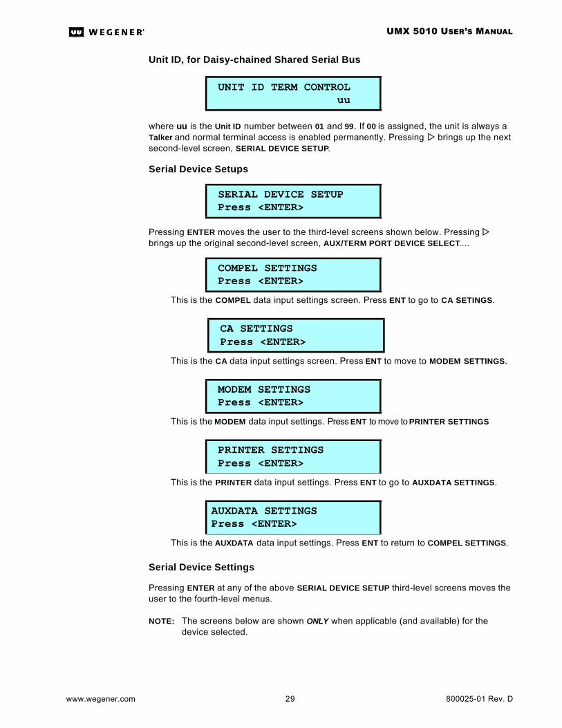
Unit ID, for Daisy-chained Shared Serial Bus
where uu is the Unit ID number between 01 and 99. If 00 is assigned, the unit is always a Talker and normal terminal access is enabled permanently. Pressing ww brings up the next second-level screen, SERIAL DEVICE SETUP.
Serial Device Setups
Pressing ENTER moves the user to the third-level screens shown below. Pressing ww brings up the original second-level screen, AUX/TERM PORT DEVICE SELECT....
Serial Device Settings
Pressing ENTER at any of the above SERIAL DEVICE SETUP third-level screens moves the user to the fourth-level menus.
NOTE: The screens below are shown ONLY when applicable (and available) for the device selected.
UNIT ID TERM CONTROL uu
SERIAL DEVICE SETUP Press <ENTER>
COMPEL SETTINGS Press <ENTER>
This is the COMPEL data input settings screen. Press ENT to go to CA SETINGS.
CA SETTINGS Press <ENTER>
This is the CA data input settings screen. Press ENT to move to MODEM SETTINGS.
MODEM SETTINGS Press <ENTER>
This is the MODEM data input settings. Press ENT to move to PRINTER SETTINGS
PRINTER SETTINGS Press <ENTER>
This is the PRINTER data input settings. Press ENT to go to AUXDATA SETTINGS.
AUXDATA SETTINGSPress <ENTER>
This is the AUXDATA data input settings. Press ENT to return to COMPEL SETTINGS.
UMX 5010 USER’S MANUAL
800025-01 Rev. D 30 www.wegener.com
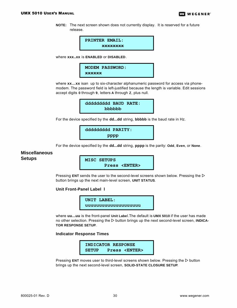
NOTE: The next screen shown does not currently display. It is reserved for a future release.
where xxx..xx is ENABLED or DISABLED.
where xx…xx isan up to six-character alphanumeric password for access via phone-modem. The password field is left-justified because the length is variable. Edit sessions accept digits 0 through 9, letters A through Z, plus null.
For the device specified by the dd...dd string, bbbbb is the baud rate in Hz.
For the device specified by the dd...dd string, pppp is the parity: Odd, Even, or None.
Miscellaneous Setups
Pressing ENT sends the user to the second-level screens shown below. Pressing the ww button brings up the next main-level screen, UNIT STATUS.
Unit Front-Panel Label l
where uu...uu is the front-panel Unit Labe l.The default is UMX 5010 if the user has made no other selection. Pressing the ww button brings up the next second-level screen, INDICA-TOR RESPONSE SETUP.
Indicator Response Times
Pressing ENT moves user to third-level screens shown below. Pressing the ww button brings up the next second-level screen, SOLID-STATE CLOSURE SETUP.
PRINTER EMAIL: xxxxxxxx
MODEM PASSWORD: xxxxxx
ddddddddd BAUD RATE: bbbbbb
ddddddddd PARITY: pppp
MISC SETUPS Press <ENTER>
UNIT LABEL: uuuuuuuuuuuuuuuuuuuu
INDICATOR RESPONSE SETUP Press <ENTER>

UMX 5010 USER’S MANUAL
www.wegener.com 31 800025-01 Rev. D
where mm:ss is the number of minutes and seconds allowed to elapse after the loss of WCI COMPEL packets on the COMPEL Input before an indication (warning or alarm) is shown.
where mm:ss is the number of minutes and seconds allowed to elapse after the loss of WCI COMPEL/CA ciphered messages on the CA Input before an indication (warning or alarm) is shown.
where mm:ss is the number of minutes and seconds allowed to elapse after the loss of Aux Data on the AUX/TERM Input (only applicable when the AUX DATA device is selected) before an indication (warning or alarm) is shown. (Loss of data is indicated by loss of any valid data received by the UART.)
User (solid-state) Contact Closures
Pressing ENTER moves user to third-level screens shown below. Pressing the ww button brings up the next second-level screen, UNIT SOFTWARE SWITCH TO B-UP.
where xx...xx is the currently selected setting (Open, Closed, or Follow Encr State) of Con-tact Closure #1. If the contact closure follows the CA state, then it is Closed for CA active, and Open for CA inactive (Off).
where xx...xx is the currently selected setting (Open or Closed) of Contact Closure #2.
COMPEL IN: mm:ss
COND. ACCESS IN: mm:ss
AUXILIARY DATA IN: mm:ss
SOLID-STATE CLOSURE SETUP? Press <ENTER>
CONTACT #1 STATUS: xxxxxxxxxxxxxx
CONTACT #2 STATUS: xxxxxxxxxxxxxx

UMX 5010 USER’S MANUAL
800025-01 Rev. D 32 www.wegener.com
Alarm Latching Enable
where pressing ENT leads the user to ALARM LATCHING EDIT screen below.
where xx...xx is either ENABLE or DISABLE, and controls whether Alarm Latching is ON or OFF.
Application Software Switch
where pressing ENTER leads the user to the third-level screens below. Pressing ww brings up the next second-level screen, TO RESET UNIT.
where xxxx is the version string of the currently running software, and yyyy is the version string of the backup software to which the unit will be switched.
NOTE: Activating the UNIT SOFTWARE SWITCH will cause a Unit Reset.)
Reset Unit
Pressing ENTER forces the iPump unit to reset immediately. Pressing ww brings up the orig-inal second-level screen under MISC SETUPS, UNIT LABEL.
Unit Status
Pressing ENTER sends the user to second-level screens shown below. Pressing ww brings up the next main-level screen, NETWORK CNTL STATUS.
ASI Transport
Pressing ENTER sends the user to third-level screens shown below. Pressing ww brings up the next second-level screen, COMPEL STRM STATUS.
ALARM LATCHING SETUP Press <ENTER>
ALARM LATCHING xxxxxxxxxxx
UNIT SOFTWARE SWITCH TO B-UP Press <ENTER>
SW FROM xxxxx TO yyyy Press <ENTER>
TO RESET UNIT: Press <ENTER>
UNIT STATUS Press <ENTER>
ASI TRANSPORT STATUS Press <ENTER>

UMX 5010 USER’S MANUAL
www.wegener.com 33 800025-01 Rev. D
where xx...xx is either LOCKED or UNLOCKED. This indication will dynamically update.
where nnn is the total number of lost-lock events logged on the currently selected ASI port and hhhh:mm:ss is the time since the last lost-lock event occurred. (The second line will read LAST EVT: N/A, if no events have occurred since last CLEAR LOG command.) Press-ing ww brings up the third-level screen, CURRENT STATUS, shown below under COMPEL STRM.
COMPEL Stream
Pressing ENTER sends the user to third-level screens shown below. Pressing ww brings up the next second-level screen, COND ACCESS STRM STATUS.
where xx...xx is either PRESENT or NOT PRESENT. This indication will dynamically update.
where nnn is the total number of lost-input events logged on that serial input. And hhhh:mm:ss is the time since the last lost-lock event occurred. (The second line will read LAST EVT: N/A, if no events have occurred since last CLEAR LOG command.)
CA Stream
Pressing ENTER sends the user to third-level screens shown below. Pressing ww brings up the next second-level screen, DATA INJECT BUFFER.
where xx...xx is either PRESENT or NOT PRESENT. This indication will dynamically update.
CURRENT STATUS: PORT Y xxxxxxx
LOST LOCKS: nnnnn LAST EVT: hhhh:mm:ss
CONTROL STRM STATUS Press <ENTER>
CURRENT STATUS: xxxxxxxxxx
LOST-INPUTS: nnnnnn LAST EVT: hhhh:mm:ss
COND ACCESS STREAMSTATUS Press <ENTER>
CURRENT STATUS: xxxxxxxxxx

UMX 5010 USER’S MANUAL
800025-01 Rev. D 34 www.wegener.com
where nnn is the total number of lost-inputs events logged on that serial number and hhhh:mm:ss is the time since the last lost-lock event occurred. (The second line will read LAST EVT: N/A, if no events have occurred since last CLEAR LOG command.)
Aux Data Stream
NOTE: The following screen is only shown if an AUX DATA device is assigned to the AUX/TERM serial port.
Pressing ENTER sends the user to third-level screens shown below.
where xx...xx is either PRESENT or NOT PRESENT. This indication will dynamically update.
where nnn is the total number of lost-input events logged on that serial input and hhhh:mm:ss is the time since the last-lock event occurred. (The second line will read LAST EVT: N/A, if no events have occurred since last CLEAR LOG command.)
Serial Data Injection Buffer
Pressing ENTER sends the user to the third-level screens shown below. Pressing ww brings up the next second-level screen, TRANSPORT STREAM STATUS.
where xx...xx is either OK, >75% (in the last ~30 seconds), or OVERFLOW (in the last ~30 seconds). This indication will dynamically update.
where nnn is the total number of buffer overflow events logged on that serial input and hhhh:mm:ss is the time since the buffer overflow event occurred. (The second line will read LAST EVT: N/A, if no events have occurred since last CLEAR LOG command.).
LOST-INPUTS: nnnnn LAST EVT: hhhh:mm:ss
AUX DATA STREAM STATUS Press <ENTER>
CURRENT STATUS: xxxxxxxxxx
LOST-INPUTS: nnnnnn LAST EVT: hhhh:mm:ss
DATA INJECT BUFFERSTATUS Press <ENTER>
CURRENT STATUS: xxxxxxxxxx
BUF OVERFLOWS: nnnnn LAST EVT: hhhh:mm:ss

UMX 5010 USER’S MANUAL
www.wegener.com 35 800025-01 Rev. D
Transport Stream Status
Pressing ENTER sends the user to the third-level screens shown below. Pressing ww brings up the next second-level screen, TIME SINCE LOG CLEARED.
where xxx.xxx is the transport stream DATA RATE (averaged over 10 seconds).
where xxxxx.xx is the NULL packet bandwidth in the transport stream (averaged over 10 seconds).
where xx.x is the percentage of all NULL packets being used.
Time Since Log Was Cleared
where hhhh:mm:ss is the time since the log was last cleared. Pressing ww brings up the next second-level screen, Clear Logs.
Clear Logs
Pressing ENTER clears the non-volatile event logs displayed in this section. After pressing ENTER, a message will be displayed indicating that the logs have been cleared.Pressing ww brings up the original second-level screen under UNIT STATUS, ASI TRANSPORT STA-TUS.
Network Control Status
NOTE: This branch of the menu tree is only shown when COMPEL control is available:
Pressing ENTER sends the user to second-level INFO screens. Pressing ww brings up the next main-level screen, CURRENT VERSION INFO.
NOTE: All counters listed in this section reset to zero at unit reset, and count up indefinitely afterward.
TRANSPORT STREAM STATUS Press <ENTER>
ESTIMATED DATA RATE xxx.xxx Mbps
NULL PCKT BANDWIDTH: xxxxx.xx Kbps
NULL PCKT %% USED: xxx.x%
TIME SINCE LOGCLEARED: hhhh:mm:ss
To Clear Event Logs Press <ENTER>
NETWORK CNTL STATUS Press <ENTER>

UMX 5010 USER’S MANUAL
800025-01 Rev. D 36 www.wegener.com
Delay before execution of COMPEL command (refer to the COMPEL ICD), where hh:mm:ss is time in hours, minutes, seconds. If no delay is applicable, N/A will be shown in place of a time.
where ss...ss is unit serial number, xx...xx is the COMPEL LOCK status (LOCKED or UNLOCKED) and yy...yy is the COMPEL REQUIRED status (REQUIRED or NOT REQUIRED).
where xx...xx is the LOCAL CONTROL ENABLE status (ENABLED or DISABLED) and yy...yy is the NETWORK PROTECTION mode (PROTECTD or SHARED).
where LAST HDR specifies the elapsed time (hhh:mm:ss) since the last COMPEL packet with a valid network header was received, and LAST ADR specifies the elapsed time (hhh:mm:ss) since the last COMPEL packet with a valid header was addressed to this particular IRD.
where HISTORY specifies the elapsed time (hhh:mm:ss) since the unit’s last reset. xx...xx is the total number of COMPEL packets processed (including Keep-alives). See the COMPEL ICD for additional information.
where xx...xx is the total number of COMPEL packets with INVALID HEADERS received. yy...yy is the total number of COMPEL packets received whose computed checksums did not match the transmitted values.
where xx...xx is the total number of COMPEL packets received whose length did not appear to match the transmitted LENGTH value. yy...yy is the total number of times the BUFFER (storage space) for COMPEL packet processing was exceeded, and some pack-ets were lost.
DELAYING: hh:mm:ss
S/N:ssssss xxxxxxxx COMPEL: yyyyyyyyyyyy
LOCAL CTRL: xxxxxxxx NETWRK MODE: yyyyyyyy
LAST HDR: hh:mm:ss LAST ADR: hh:mm:ss
HISTORY: hhhh:mm:ss TOT PROCESSED xxxxxx
INVALID HEADR: xxxxxx INVALID CKSUM: yyyyyy
INVALID LENGTH: xxxxx BUFFER OVRFLOW: yyyyy

UMX 5010 USER’S MANUAL
www.wegener.com 37 800025-01 Rev. D
where xx...xx is the total number of COMPEL packets received with SYNTAX ERRORS.
Current Version Information
NOTE: The following screens may be used to get information on the currently loaded application software and other programmable components.
Pressing ENTER moves user to second-level screens under VERSION. Pressing ww brings up the next main-level screen, NAVIGATION HELP.
xx...xx is version number of the current unit application software.
xx...xx is version number of the backup unit application software (if it exists).
where xx...xx is version number of the boot loader code.
where x is a hex code for the Main Processor PWB assembly revision level (A=1, B=2, etc.) and y is a hex code for TYPE (one of a series of parts lists built on a PWB, where 700011-03 is Type 3).
where xx...xx is the version string of the installed Xilinx FPGA programming software on the MP PWA .
where xx...xx is the version string of the installed Lattice CPLD programming software on the MP PWA .
SYNTAX ERRORS: xxxxxxx
CURRENT VERSION INFO Press<ENTER>
APPLICATION CURRENT: xxxxxx
APPLICATION BACKUP: xxxxxx
BOOT LOADER: xxxxxx
MP PWA VERSION: xy xy
MP XILINX VERSION: xxxxxxxx
MP LATTICE VERSION: xxxxxxxx
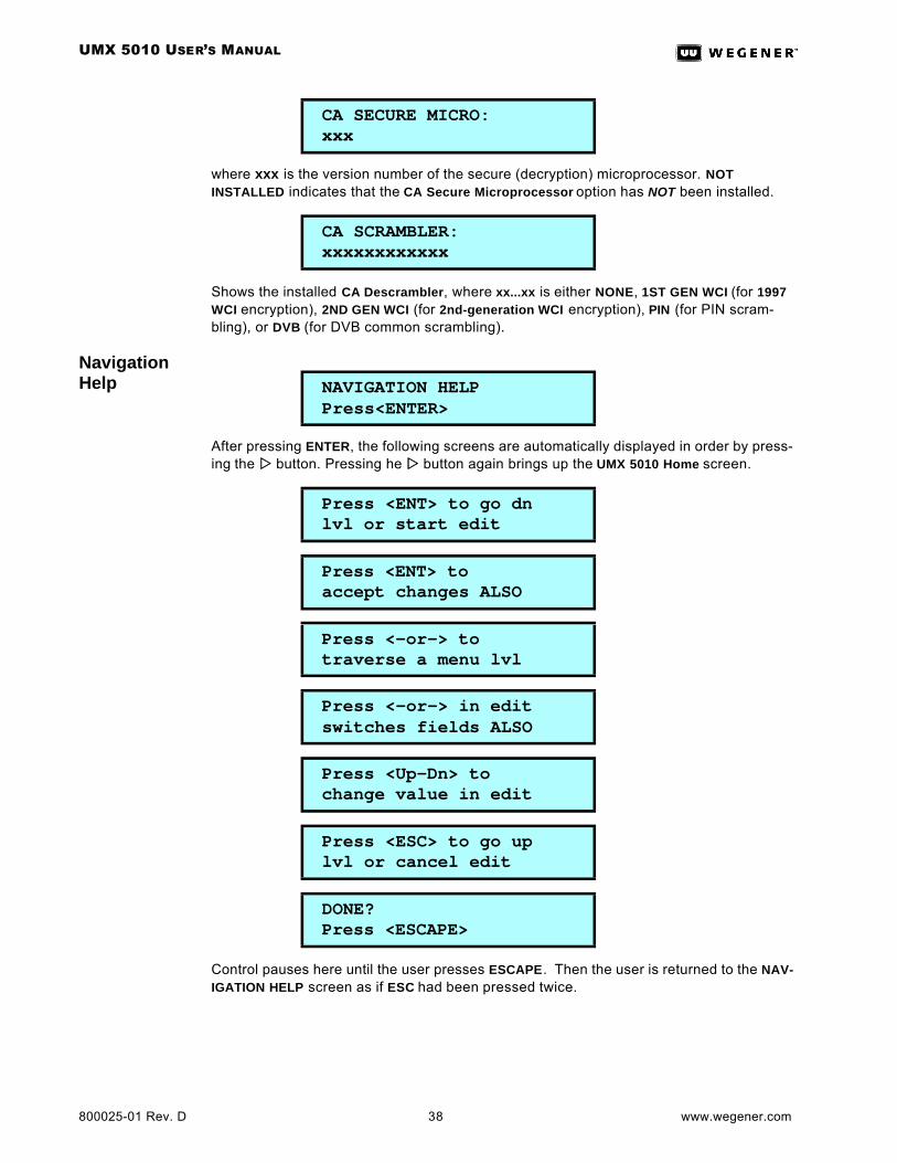
UMX 5010 USER’S MANUAL
800025-01 Rev. D 38 www.wegener.com
where xxx is the version number of the secure (decryption) microprocessor. NOT INSTALLED indicates that the CA Secure Microprocessor option has NOT been installed.
Shows the installed CA Descrambler, where xx...xx is either NONE, 1ST GEN WCI (for 1997 WCI encryption), 2ND GEN WCI (for 2nd-generation WCI encryption), PIN (for PIN scram-bling), or DVB (for DVB common scrambling).
Navigation Help
After pressing ENTER, the following screens are automatically displayed in order by press-ing the ww button. Pressing he ww button again brings up the UMX 5010 Home screen.
Control pauses here until the user presses ESCAPE. Then the user is returned to the NAV-IGATION HELP screen as if ESC had been pressed twice.
CA SECURE MICRO: xxx
CA SCRAMBLER: xxxxxxxxxxxx
NAVIGATION HELP Press<ENTER>
Press <ENT> to go dn lvl or start edit
Press <ENT> to accept changes ALSO
Press <-or-> to traverse a menu lvl
Press <-or-> in edit switches fields ALSO
Press <Up-Dn> to change value in edit
Press <ESC> to go up lvl or cancel edit
DONE? Press <ESCAPE>
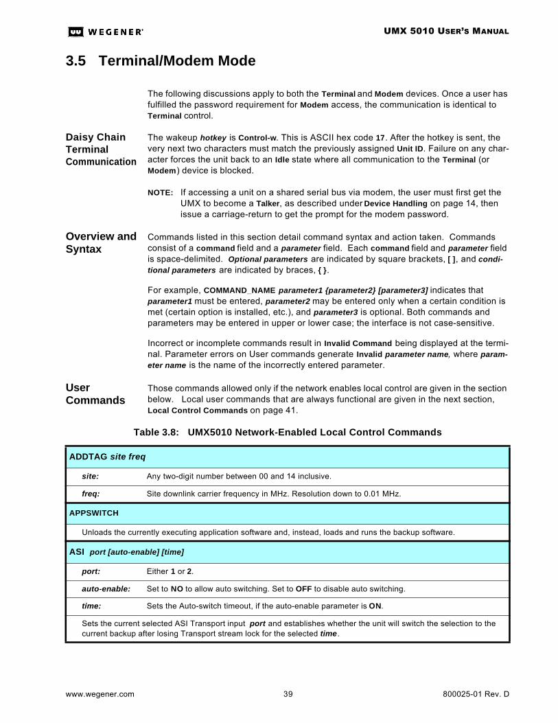
UMX 5010 USER’S MANUAL
www.wegener.com 39 800025-01 Rev. D
3.5 Terminal/Modem Mode
The following discussions apply to both the Terminal and Modem devices. Once a user has fulfilled the password requirement for Modem access, the communication is identical to Terminal control.
Daisy Chain Terminal Communication
The wakeup hotkey is Control-w. This is ASCII hex code 17. After the hotkey is sent, the very next two characters must match the previously assigned Unit ID. Failure on any char-acter forces the unit back to an Idle state where all communication to the Terminal (or Modem) device is blocked.
NOTE: If accessing a unit on a shared serial bus via modem, the user must first get the UMX to become a Talker, as described under Device Handling on page 14, then issue a carriage-return to get the prompt for the modem password.
Overview and Syntax
Commands listed in this section detail command syntax and action taken. Commands consist of a command field and a parameter field. Each command field and parameter field is space-delimited. Optional parameters are indicated by square brackets, [ ], and condi-tional parameters are indicated by braces, .
For example, COMMAND_NAME parameter1 parameter2 [parameter3] indicates that parameter1 must be entered, parameter2 may be entered only when a certain condition is met (certain option is installed, etc.), and parameter3 is optional. Both commands and parameters may be entered in upper or lower case; the interface is not case-sensitive.
Incorrect or incomplete commands result in Invalid Command being displayed at the termi-nal. Parameter errors on User commands generate Invalid parameter name, where param-eter name is the name of the incorrectly entered parameter.
User Commands
Those commands allowed only if the network enables local control are given in the section below. Local user commands that are always functional are given in the next section, Local Control Commands on page 41.
Table 3.8: UMX5010 Network-Enabled Local Control Commands
ADDTAG site freq
site: Any two-digit number between 00 and 14 inclusive.
freq: Site downlink carrier frequency in MHz. Resolution down to 0.01 MHz.
APPSWITCH
Unloads the currently executing application software and, instead, loads and runs the backup software.
ASI port [auto-enable] [time]
port: Either 1 or 2.
auto-enable: Set to NO to allow auto switching. Set to OFF to disable auto switching.
time: Sets the Auto-switch timeout, if the auto-enable parameter is ON.
Sets the current selected ASI Transport input port and establishes whether the unit will switch the selection to the current backup after losing Transport stream lock for the selected time.

UMX 5010 USER’S MANUAL
800025-01 Rev. D 40 www.wegener.com
CA param
param: C for Clear forces CA OFF. E for External forces the unit to follow the setting from the external sys-tem.
CA override: Allows the external key management system (usually COMPEL/CA) to dictate the activation of the encryption scrambler or forces it OFF regardless of the external system’s instructions.
DELTAG site
site: Any two digit number between 00 and 14 inclusive or ALL to delete all tags.
Deletes a Carrier ID tag site (or all tags) from the Tag Table.
FIXKEY on/off
on/off: ON fixes the last de-ciphered key as the scrambling key indefinitely. OFF forces the unit to use new keys as they are input on the CA port and de-ciphered. Omitting the parameter while using fixed keys will cause the next de-ciphered key to replace the previous fixed key. (Otherwise there is no effect.)
Fixes/releases the scrambling key or allows an update to the last deciphered key.
PINKEY value
value: Decimal value of PIN code, between 0 and 16,777,215.
Sets the PIN scrambling key value. Omitting the parameter reveals the current setting.
SETPID input PID [priority]
input: Input data stream: either CP (for COMPEL), CA, or AUX (for Aux data).
PID: Selects the PID (in hex!) for the Transport packets carrying the desired data stream. Must be 20 to 1FFE inclusive.
priority: Either L (for Latency time) or B (for Bandwidth). If omitted alone, then the previously assigned (or factory default) value is retained.
Sets the transport packet PID used for injection of the specified input data stream at the priority specified.
RE state [number]
state: O (for Open), C (for Close), or (for contact #1 only) F meaning Follow CA scrambling state.
number: 1 or 2, indicating the affected user solid-state contact. Both are specified if omitted.
The specified solid-state contact is opened or closed accordingly.
SETLABEL label
label: Unit label. Field entry is truncated at 10 characters.
Sets Unit Label displayed on UMX Home LCD screen (and Terminal Welcome Banners).
Table 3.8: UMX5010 Network-Enabled Local Control Commands

UMX 5010 USER’S MANUAL
www.wegener.com 41 800025-01 Rev. D
Local Control Commands
Local Control commands that are always functional at the UMX 5010 Terminal are listed in Table 3.9 below. ( Command that are allowed only if local control is enabled by the COMPEL network are listed above in Table 3.8.)
SCR type [partition]
type: Either PIN (for PIN scrambling), 97CA (for legacy 1997 WCI CA), 02CA (for WCI CA with 2002 upgrade), or NONE.
partition: If the PCA type is selected, partition sets the borderline PID value in hex at and above which all non-NULL transport packets are scrambled. If not supplied, then the previously selected (or factory default) setting is used.
Sets the scrambling type.
NOTE: When using 2002 COMPEL/CA, if the KMS stream is disrupted or if the ciphered scrambling seeds fail to reach the UMX 5010, the unit will turn off scrambling and put the signal "in the clear" at least for the remain-der of that odd/even seed distribution period (typically one to two minutes). Using 1997 COMPEL/CA under the same conditions, the UMX 5010 will keep the signal scrambled even with the risk that downstream IRDs will "go dark".
Table 3.8: UMX5010 Network-Enabled Local Control Commands
Table 3.9: UMX 5010 Local Terminal Commands
CLRDIAG
Command clears all the diagnostic log counters for lost transport, lost inputs, buffer overflows, etc.
H [command]
command: Any of the terminal command names (PC, R, PORT, etc.).
If an H or any invalid command beginning with an H is entered and the command parameter is omitted, the whole Help screen will be displayed, consisting of a list of all currently available commands and a brief description of each. If an H or any invalid command beginning with an H is entered and the command parameter is a valid User Com-mand Name, then detailed help for the specified command will be displayed.
LATCHALARMS x
x: Either E for Enable or D for Disable.
Command turns Alarm Latching ON or OFF.
OH
On hook. Disables modem access. Modem access is only re-enabled by successful modem password entry.
PC device baud
device: One of MODEM, TERMINAL, AUXDATA , CA, or COMPEL.
baud: 1200, 2400, 4800, 9600, 19200 or 38400 (or 115200 for AUX DATA only).
parity: N (none), E (even), or O (odd).
Configures communication parameters for any serial device. See Serial Inputs Setups on page 28 for details.
PORT device
device: Device assigned to the AUX/TERM port, either TERMINAL, MODEM or AUXDATA.
Assigns the given device to the Aux/Term port.
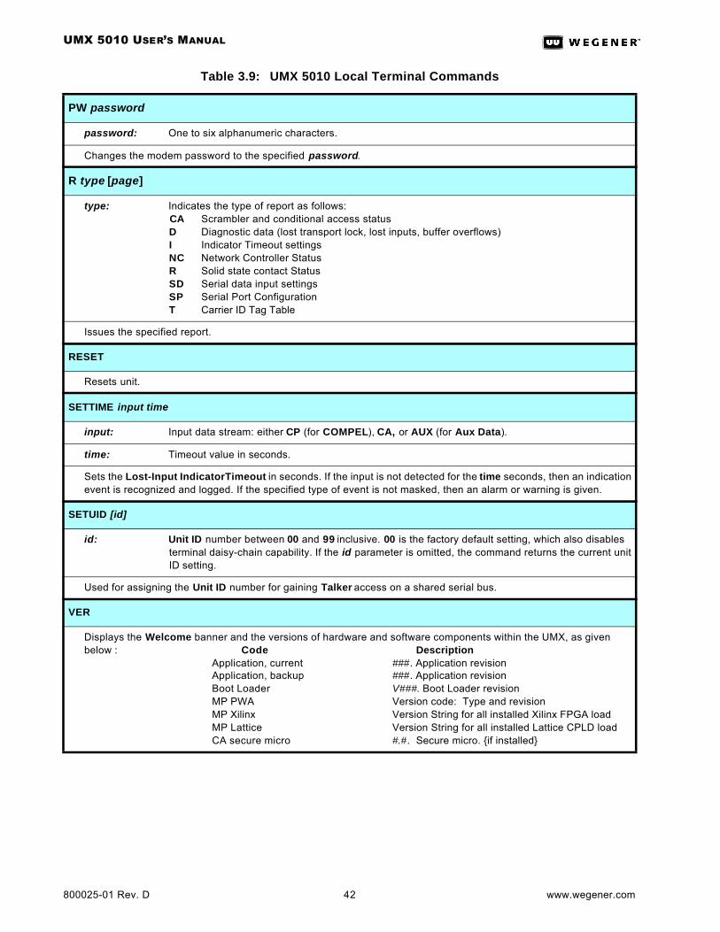
UMX 5010 USER’S MANUAL
800025-01 Rev. D 42 www.wegener.com
PW password
password: One to six alphanumeric characters.
Changes the modem password to the specified password.
R type [page]
type: Indicates the type of report as follows:CA Scrambler and conditional access statusD Diagnostic data (lost transport lock, lost inputs, buffer overflows)I Indicator Timeout settingsNC Network Controller StatusR Solid state contact StatusSD Serial data input settingsSP Serial Port ConfigurationT Carrier ID Tag Table
Issues the specified report.
RESET
Resets unit.
SETTIME input time
input: Input data stream: either CP (for COMPEL), CA, or AUX (for Aux Data).
time: Timeout value in seconds.
Sets the Lost-Input IndicatorTimeout in seconds. If the input is not detected for the time seconds, then an indication event is recognized and logged. If the specified type of event is not masked, then an alarm or warning is given.
SETUID [id]
id: Unit ID number between 00 and 99 inclusive. 00 is the factory default setting, which also disables terminal daisy-chain capability. If the id parameter is omitted, the command returns the current unit ID setting.
Used for assigning the Unit ID number for gaining Talker access on a shared serial bus.
VER
Displays the Welcome banner and the versions of hardware and software components within the UMX, as given below : Code Description
Application, current ###. Application revisionApplication, backup ###. Application revisionBoot Loader V###. Boot Loader revisionMP PWA Version code: Type and revisionMP Xilinx Version String for all installed Xilinx FPGA loadMP Lattice Version String for all installed Lattice CPLD loadCA secure micro #.#. Secure micro. if installed
Table 3.9: UMX 5010 Local Terminal Commands

UMX 5010 USER’S MANUAL
www.wegener.com 43 800025-01 Rev. D
Report Screens
Scrambler and Conditional Access Status Report (Terminal Command: R CA)This report lists:
1. Current Scrambler assignment (PIN, 1997 WCI CA, or PARTITIONED CA),
2. CA Override status (CLEAR or EXTERNALLY SET),
3. PIN scrambling key,
4. Fixed Key status (for CA).
Diagnostic Data Report (Terminal Command: R D )
This report lists:
1. ASI port lock status (LOCKED or UNLOCKED) and whether current status was set manually or forced by auto-switch
2. Number of ASI lost-lock events on the current ASI port.
3. Time since the last ASI lost-lock event occurred (hhhh:mm:ss or N/A if no events have occurred since last CLEAR LOG command).
4. Current COMPEL Control Stream Status (PRESENT or NOT PRESENT).
5. Number of lost-input events on the COMPEL input stream.
6. Time since the last COMPEL lost-input event occurred (hhhh:mm:ss or N/A if no events have occurred since last CLEAR LOG command).
7. Current CA Stream Status (PRESENT or NOT PRESENT).
8. Number of lost-input events on the CA input stream.
9. Time since the last CA lost-input event occurred (hhhh:mm:ss or N/A if no events have occurred since last CLEAR LOG command).
10. Current Aux Data Stream Status (PRESENT or NOT PRESENT).
11. Number of lost-input events on the Aux Data input stream.
12. Time since the last Aux Data lost-input event occurred (hhhh:mm:ss or N/A if no events have occurred since last CLEAR LOG command).
13. Current Transport Injection Buffer Status (OK, >75%, overflowed in last 5 minutes)
14. Number of Transport Injection Buffer Overflows
15. Time since the last Transport Injection Buffer Overflow (hhhh:mm:ss or N/A if no events have occurred since last CLEAR LOG command).
16. Estimated Tansport stream Data Rate (averaged over 10 seconds).
17. Transport Stream NULL Packet Bandwidth (averaged over 10 seconds).
18. Transport NULL packet % used (percentage of all NULL packets being used).
Indicator Timeout Settings Report (Terminal Command: R I)
This report lists:
1. Indicator Response Time for the COMPEL stream input, in hh:mm:ss format.
2. Indicator Response Time for the CA stream input, in hh:mm:ss format.
3. Indicator Response Time for the AUX Data stream input, in hh:mm:ss format.
UMX 5010 USER’S MANUAL
800025-01 Rev. D 44 www.wegener.com
Network Control Status (Terminal Command: R NC)
This report lists the subset of the following supported in this release:
1. Unit Serial Number
2. Unit Label
3. Network Header
4. COMPEL Lock Status (LOCKED or UNLOCKED)
5. Local Control Enable Status (ENABLE or DISABLE)
6. Network Protection Mode (PROTECTD or SHARED)
7. Time (hhh:mm:ss) since last COMPEL packet with valid network header received
8. Time (hhh:mm:ss) since last COMPEL packet with valid header addressed to unit.
9. Total HISTORY, the time (hhh:mm:ss) elapsed since the unit’s last reset.
10. Total no.of COMPEL packets processed (incl. Keep-alives) since last unit reset.
11. Number of COMPEL packets with Invalid Headers received.
12. Number of COMPEL packets with Invalid Checksums received.
13. Number of COMPEL packets with Invalid Lengths received.
14. Number of COMPEL packet processing Buffer Overflows.
15. Number of COMPEL packets received with Syntax Errors.
Solid State Contacts Status (Terminal Command: R R)
The report lists all solid state contacts by contact number and the state of each (OPEN, CLOSED, or FOLLOW CA).
Serial Data Input Settings (Terminal Command: R SD)
For each of the three basic injected streams (COMPEL, CA, AUX data), this report lists the assigned PID (in hex) and each stream’s Priority (either Latency or Bandwidth).
Serial Port Configuration (Terminal Command: R SP)
This report lists:
1. The Device currently assigned to the Aux/Term port (MODEM, TERMINAL, AUX-DATA, PRINTER, NONE, or LOCAL COMPEL).
2. COMPEL device setup (baud rate, data-bits, parity, stop bits)
3. CA device setup (baud rate, data-bits, parity, stop bits)
4. Terminal device setup (baud rate, data-bits, parity, stop bits)
5. Modem device setup (baud rate, data-bits, parity, stop bits)
6. Aux Data device setup (baud rate, data-bits, parity, stop bits)
Tag Site Table Report (Terminal Command: R T)
This report lists all possible tag sites 00 through 14 with a single parameter field for each that displays a frequency (xxxxx.xx MHz) or NOT ASSIGNED.

UMX 5010 USER’S MANUAL
www.wegener.com 45 800025-01 Rev. D
CHAPTER 4 MAINTENANCE AND TROUBLESHOOTING
4.1 MaintenanceMaintenance of the UMX 5010 is limited to keeping the chassis clean and ensuring that cables remain firmly connected. Occasionally wipe the exterior with a soft, damp cloth to remove any accumulated dust and dirt and check that cables are securely attached.
The UMX 5010 incorporates security labels over some of the screws. There are no user-serviceable components within the UMX 5010. Tampering with the security labels or open-ing the unit will void your warranty. If you have any questions, contact Wegener’s Customer Service Department at the address or numbers listed under Customer Service.
4.2 TroubleshootingThis section is not intended as an exhaustive list of all possible situations. Please contact us with any problems you cannot resolve independently. (See Chapter 5 Customer Service on page 47.)
If you are experiencing any difficulties, first check the LCD and LED indicators on the UMX5010 to determine if any warnings or alarms are active. See Table 3.4: UMX 5010 Front Panel LED Indicator Descriptions on page 12 for descriptions of LED states.
No Functions At All
If the unit is not functioning at all and neither the LCD nor any LEDs are lit, there may be a loss of AC power. Do the following:
a. Check that AC power cord is firmly connected at both ends.
b. Check that your AC power source is supplying AC power.
c. Press the ENT button on the front panel.
No Output If the unit is receiving power and there are no alarm or warning conditions indicated by the front panel, but there is still no output, check your ASI input connections. Also check the operation of your monitoring equipment.
LED Indicators
Use Table 3.4: UMX 5010 Front Panel LED Indicator Descriptions on page 12 to help in trou-bleshooting.
NOTE: Only one alarm or warning condition is displayed at a time on the LCD. When multiple alarm or warning conditions exist, those conditions are displayed in the order of importance. The highest priority condition is displayed first. Further alarms or warnings will be shown after the more critical item(s) is cleared.
NOTE: When using 2002 COMPEL/CA, if the KMS stream is disrupted or if the ciphered scrambling seeds fail to reach the UMX 5010, the unit will turn off scrambling and put the signal "in the clear" at least for the remainder of that odd/even seed distribution period (typically one to two minutes). Using 1997 COMPEL/CA under the same conditions, the UMX 5010 will keep the signal scrambled even with the risk that downstream IRDs will "go dark".

UMX 5010 USER’S MANUAL
800025-01 Rev. D 46 www.wegener.com
This page intentionally blank
UMX 5010 USER’S MANUAL
www.wegener.com 47 800025-01 Rev. D
CHAPTER 5 CUSTOMER SERVICE
5.1 WarrantyThe following warranty applies to all Wegener Communications products including the UMX 5010 UnityMux:
All Wegener Communications products are warranted against defective materials and workmanship for a period of one year after shipment to customer. Wegener Communications ' obligation under this warranty is limited to repairing or, at Wege-ner Communications' option, replacing parts, subassemblies, or entire assemblies. Wegener Communications shall not be liable for any special, indirect, or conse-quential damages. This warranty does not cover parts or equipment which have been subject to misuse, negligence, or accident by the customer during use. All shipping costs for warranty repairs will be prepaid by the customer. There are no other warranties, express or implied, except as stated herein.
5.2 Technical SupportIf the unit should fail to perform as described, if you need help resolving problems with your UMX 5010, or for questions about obtaining service for your UMX 5010, contact Wegener Communications Customer Service at (770) 814-4057, FAX (678) 624-0294, or e-mail [email protected].
To return a product for service:
a. Obtain a Return Material Authorization (RMA) number by completing and faxing a copy of the RMA Request Form to (678) 624-0294. You may e-mail the same information instead to: [email protected].
b. To help us identify and control returned units, plainly write the RMA number on the outside of the product-shipping container. This will help us return your unit to you as quickly as possible.
c. Return the product, freight prepaid, to the address below:
Service Department RMA# ________Wegener Communications, Inc.359 Curie DriveAlpharetta, GA 30005
NOTE: All returned material must be shipped freight prepaid. C.O.D. Shipments will not be accepted.

UMX 5010 USER’S MANUAL
800025-01 Rev. D 48 www.wegener.com
This page intentionally left blank.
UNITY MUX 5010 USER’S MANUAL
www.wegener.com 49 800025-01 Rev. D
INDEX
Aac power connector . . . . . . . . . . . . . 7
agency approvals . . . . . . . . . . . . . . 4
air flow for safe operation . . . . . . . . 5
ALARM LED . . . . . . . . . . . . . . . . . 13
alarm/warning conditions, display of . . . . . . . . . . . . . . . . . 45
alarm/warning relays . . . . . . . . . . 3, 8
alternate main-level screen, conditions for . . . . . . . . . . . . . . 20
amperage . . . . . . . . . . . . . . . . . . . . 3
anchor screws . . . . . . . . . . . . . . . . . 6
angle brackets . . . . . . . . . . . . . . . . . 6
application backup screen . . . . . . . 37
application current screen . . . . . . . 37
application s/w switch screen . . . . 32
approvals by agency . . . . . . . . . . . . 4
arrow buttons . . . . . . . . . . . . . . . . . 10
ASI transport input/output . . . . . . . . 8
ASI transport screen . . . . . . . . 19, 32
async data input . . . . . . . . . . . . . . 13
aux data input setup screen . . 17, 26
aux data settings screen . . . . . . . . 18
aux data stream screen . . . . . . 19, 34
AUX IN LED . . . . . . . . . . . . . . . . . . 13
aux/term port . . . . . . . . . . . . . . . 7, 13
aux/term port device selection screen . . . . . . . . . . . . . . . . . 18, 28
auxiliary data async input . . . . . . . . 3
auxiliary data channel . . . . . . . . . . . 2
Bbackup application screen . . . . 20, 37
baud rates . . . . . . . . . . . . . . . . . . . . 2
BNC jack . . . . . . . . . . . . . . . . . . . . . 8
bolts, anchor . . . . . . . . . . . . . . . . . . 6
boot loader screen . . . . . . . . . . 20, 37
brackets, mounting . . . . . . . . . . . . . 6
buttons, front-panel . . . . . . . . . . . . 10
CCA data stream screen . . . . . . . . . 19
CA IN LED . . . . . . . . . . . . . . . . . . . 13
CA IN port . . . . . . . . . . . . . . . . . . . . 7
CA input setup screen . . . . . . . 17, 25
CA override screen . . . . . . . . . . . . 24
CA scrambler partition PID screen . . . . . . . . . . . . . . . . 17, 27
CA scrambler screen . . . . . . . 20, 38
CA secure microprocessor screen . . . . . . . . . . . . . . . . 20, 38
CA settings screen . . . . . . . . . . . . 18
CA setup screen . . . . . . . . . . . 17, 26
CA stream screen . . . . . . . . . . . . . 33
CA type screen . . . . . . . . . . . . 17, 26
cablesconnecting to unit . . . . . . . . . . . 7routing of . . . . . . . . . . . . . . . . . . 6
carrier ID tagsnumber of entries . . . . . . . . . . . . 2setup screen . . . . . . . . . . . 18, 28
CE certification . . . . . . . . . . . . . . . . 4
changes to manual, suggestions for . . . . . . . . . . . . . 1
chassisdescription . . . . . . . . . . . . . . . . . 2dimensions . . . . . . . . . . . . . . . . 3earthing . . . . . . . . . . . . . . . . . . . 6opening of . . . . . . . . . . . . . . . . . .
circuit overloading . . . . . . . . . . . . . . 6
claims of damage . . . . . . . . . . . . . . 5
classification by FCC . . . . . . . . . . . 4
cleaning the UnityMux . . . . . . . . . . 45
clear logs screen . . . . . . . . . . . 19, 35
clearance around unit . . . . . . . . . . . 5
commanding the UnityMux . . . . . . 10
comments or suggestions . . . . . . . . 1
COMPEL IN LED . . . . . . . . . . . . . 12
COMPEL input . . . . . . . . . . . . . . . . 3
COMPEL input setup screen . 17, 25
COMPEL port . . . . . . . . . . . . . . . . . 7
COMPEL settings screen . . . . . . . 18
COMPEL stream status screen 19, 33
components, user-serviceable . 4, 45
conditional access setup screen . . 26
conditions for alternate default screens . . . . . . . . . . . . . . . . . . 20
connecting the unit . . . . . . . . . . . . . 7
connection to supply circuit . . . . . . . 6
connectors, rear-panel . . . . . . . . . . 7
contacting Wegener regarding manual 1 . . . . . . . . . . . . . . . . . . . .
control stream. See COMPEL stream
controlling the UnityMux . . . . . . . . 10
controls and indicators . . . . . . . . . . .9
cross supports . . . . . . . . . . . . . . . . .6
current application screen . . . .20, 37
current of supplied power . . . . . . . . .3
current version info screen 2. . . .0, 37
DD connetor, nine-pin . . . . . . . . . . . . .7
daisy chaining serial ports . . . . . . . .3
damage claims . . . . . . . . . . . . . . . . .5
data channel, auxiliary . . . . . . . . . . .2
data inject buffer screen . . . . . . . . . 34
default LCD screens . . . . . . . . . . . . 20
depth of chassis . . . . . . . . . . . . . . . .3
description of unitfunctional . . . . . . . . . . . . . . . . . .2physical . . . . . . . . . . . . . . . . . . . .2
desktop installation . . . . . . . . . . . . . .6
desktop mounting . . . . . . . . . . . . . . .5
difficulties with the UnityMux . . . . . 45
dimensions of chassis 3 . . . . . . . . . . .
disable site . . . . . . . . . . . . . . . . . . . 18
display, front-panel . . . . . . . . . . . . . .9
down-arrow button . . . . . . . . . . . . . 10
DVB ASI input/output 2
DVB ASI ports . . . . . . . . . . . . . . . . .8
Eearthing . . . . . . . . . . . . . . . . . . . . . .6
edit mode, LCD . . . . . . . . . . . . .9, 11
edit or disable site . . . . . . . . . . . . .18
editing parameters . . . . . . . . . . . . . .9
elevated operating ambient . . . . . . . 5
e-mailcustomer service . . . . . . . . . . . . 47reading . . . . . . . . . . . . . . . . . . . 23regarding manual . . . . . . . . . . . .1viewing messages . . . . . . . . . . .9
email screen . . . . . . . . . . . . . . . . . . 17
ENCRYPT ON LED . . . . . . . . . . . . 12
encryption control table screen . . . . . . . . . . . . . . . . .17, 27
enter (ENT) button . . . . . . . . . . . . . 10
environment for mounting . . . . . . . .5
environmental specifications for the UnityMux . . . . . . . . . . . . .4
equipment earthing . . . . . . . . . . . . .6
UNITY MUX 5010 USER’S MANUAL
800025-01 Rev. D 50 www.wegener.com
equipment power ratings . . . . . . . . . 6
equipment rack . . . . . . . . . . . . . . 5, 6
escape (ESC) button . . . . . . . . . . 10
Ethernet cable, shielding of . . . . . . 5
Ethernet port . . . . . . . . . . . . . . 2, 3, 7
European certification . . . . . . . . . . . 4
even key scrambling . . . . . . . . . . . 12
Ffax number
customer service . . . . . . . . . . . 47manuals . . . . . . . . . . . . . . . . . . . 1
FCC classification . . . . . . . . . . . . . . 4
FCC-mandated emissions suppres-sion . . . . . . . . . . . . . . . . . . . . . . 5
Federal Communications Commission . . . . . . . . . . . . . . . . 4
fixed key encryption screen . . 17, 27
formatting of serial ports . . . . . . . . . 3
frequency of supplied power . . . . . . 3
front brackets . . . . . . . . . . . . . . . . . 6
front panelillustration . . . . . . . . . . . . . . . . . 2indicators . . . . . . . . . . . . . . . . . . 9LEDs . . . . . . . . . . . . . . . . . . . . 12operation from . . . . . . . . . . . . . . 9
front-panel display . . . . . . . . . . . . . 9
functional description . . . . . . . . . . . 2
Ggrounding . . . . . . . . . . . . . . . . . . . . 6
Hhandshaking . . . . . . . . . . . . . . . . . . 2
height of chassis . . . . . . . . . . . . . . . 3
help screen, navigation . . . . . . 20, 38
hierarchy, menu screens . . . . . . . . 17
home screen . . . . . . . . . . . . . . . . . 21
housing . . . . . . . . . . . . . . . . . . . . . . 2
humidity, maximum . . . . . . . . . . . . . 4
IIEC receptacle . . . . . . . . . . . . . . . . 7
illustrationfront panel . . . . . . . . . . . . . . . . . 9front-panel LEDs . . . . . . . . . . . 12pushbuttons . . . . . . . . . . . . . . . 10rear panel . . . . . . . . . . . . . . . . . 7
indication time variable . . . . . . . . . 12
indicator descriptions . . . . . . . . . . 45
indicator response setup screen . . . . . . . . . . . . . . . . .18, 30
indicator screens, software download . . . . . . . . . . . . . . . . . 17
indicators, UnityMux . . . . . . . . . . . . .9
info type screen . . . . . . . . . . . . . . .10
injected stream setup screen . .17, 25
input, DVB ASI . . . . . . . . . . . . . . . . .2
inspecting the UnityMux . . . . . . . . . . 5
installationdesktop . . . . . . . . . . . . . . . . . . . .6rack . . . . . . . . . . . . . . . . . . . . . . .6safety during . . . . . . . . . . . . . . . .4UnityMux . . . . . . . . . . . . . . . . . . .5
interference, radio . . . . . . . . . . . . . . 5
Jjitter, PCR . . . . . . . . . . . . . . . . . . . . .2
Kkeep-alive packets . . . . . . . . . . . . .12
Llabel, unit . . . . . . . . . . . . . . . . . . . . .9
labels, security . . . . . . . . . . . . . . 4, 45
LCDdescription of . . . . . . . . . . . . . . . 9modes of 9types of screens 10
LEDALARM . . . . . . . . . . . . . . . . . . . 13AUX IN . . . . . . . . . . . . . . . . . . . 13CA IN . . . . . . . . . . . . . . . . . . . .13COMPEL IN . . . . . . . . . . . . . . .12ENCRYPT ON . . . . . . . . . . . . . 12SCR KEYS . . . . . . . . . . . . . . . . 12TRANSPORT IN . . . . . . . . . . . . 12WARNING . . . . . . . . . . . . . . . . 12
LED indicators . . . . . . . . . . . . .12, 45
left-arrow button . . . . . . . . . . . . . . . 10
light-emitting diodes (LEDs) . . . . . . 12
liquid-crystal display (LCD) . . . . . . . 9
listing by UL . . . . . . . . . . . . . . . . . . . 4
loading, mechanical . . . . . . . . . . . . .6
location and mounting . . . . . . . . . . .5
log cleared, time since 3 . . . . . . . . . . 5
lugs, grounding . . . . . . . . . . . . . . . . .6
Mmailing address
customer service . . . . . . . . . . . . 47
manual comments or questions 1
maintenance . . . . . . . . . . . . . . . . . 45
maximum relative humidity . . . . . . . 4
mechanical loading . . . . . . . . . . . . . 6
menu screensheirarchy of . . . . . . . . . . . . . . . 17type of LCD . . . . . . . . . . . . . . . 10
misc setups screen . . . . . . . . . 18, 30
modem devices . . . . . . . . . . . . . . . 39
modem password screen . . . . . . . 30
modem settings screen . . . . . . . . . 18
modem, using for remote terminal . . . . . . . . . . . . . . . . . . . 3
mountingdesktop . . . . . . . . . . . . . . . . . . . 6equipment rack . . . . . . . . . . . . . 6location and . . . . . . . . . . . . . . . . 5
MP lattice version screen . . . . . 0, 37
MP PWA ID screen . . . . . . . . . . . . 20
MP PWA version screen . . . . . . . . 37
MP Xilinx version screen . . . . . 20, 37
MPEG transport streamspacket size of . . . . . . . . . . . . . . . 2supported . . . . . . . . . . . . . . . . . . 2
multi-unit rack assembly . . . . . . . . . 5
Nnavigation help screen . . . . . . 20, 38
navigation of screens . . . . . . . . . . 10
network control status screen . 19, 35
networking applications, upgrading for . . . . . . . . . . . . . . . 2
no output from unit . . . . . . . . . . . . 45
no unit functions . . . . . . . . . . . . . . 45
Oodd key scrambling . . . . . . . . . . . . 12
opening the chassis . . . . . . . . . . . . . 4
operating ambient temperature . . . . 5
operating temperature . . . . . . . . . . . 4
operation of UnityMux . . . . . . . . . . . 9
output, DVB ASI . . . . . . . . . . . . . . . .
output, problems with . . . . . . . . . . 45
overcurrent protection . . . . . . . . . . . 6
overloaded circuits . . . . . . . . . . . . . 6
overview of UnityMux . . . . . . . . . . . 2
Ppacket size of transport stream 2 . . . .
packing materials . . . . . . . . . . . . . . 5
UNITY MUX 5010 USER’S MANUAL
www.wegener.com 51 800025-01 Rev. D
parameter screen LCD type . . . . . . 10
parameters, editing . . . . . . . . . . . . . 9
parity setting . . . . . . . . . . . . . . . . . . 3
partition scrambling enable screen . . . . . . . . . . . . . . . . . 17, 26
PCR jitter . . . . . . . . . . . . . . . . . . . . . 2
phone number, customer
service . . . . . . . . . . . . . . . . . . . . . . 47
physical description of UnityMux . . . 2
PIN scrambling key screen . . . 17, 27
PIN scrambling LED. See SCR KEYS LED
pinouts, connector . . . . . . . . . . . . 7–8
polarity of alarm/warning relays . . . . 3
port number, display of . . . . . . . . . . 9
port specificationsEthernet . . . . . . . . . . . . . . . . . . . 3RS232 serial . . . . . . . . . . . . . . . . 2
power rating of equipment . . . . . . . . 6
power specifications . . . . . . . . . . . . 3
power strips, use of . . . . . . . . . . . . . 6
precautions for safety . . . . . . . . . . . 4
printer email screen . . . . . . . . . . . . 30
printer settings screen . . . . . . . . . . 18
problems with the UnityMux . . . . . . 45
pushbuttonsdescription of . . . . . . . . . . . . . . 10functions of . . . . . . . . . . . . . . . 11illustration of . . . . . . . . . . . . . . . 10location of . . . . . . . . . . . . . . . . . . 2
Qquestions about safety . . . . . . . . . . . 4
Rrack
earthing of . . . . . . . . . . . . . . . . . 6mounting in . . . . . . . . . . . . . . . . . 6spacing in . . . . . . . . . . . . . . . . . . 5total loading of . . . . . . . . . . . . . . 6
rack assembly, temperature of . . . . 5
radiated emissions, suppressing . . . . . . . . . . . . . . . . 5
radio interference . . . . . . . . . . . . . . . 5
reading e-mail 23 . . . . . . . . . . . . . . . .
rear-panel connections . . . . . . . . . . 7
reduced air flow . . . . . . . . . . . . . . . . 5
relative humidity . . . . . . . . . . . . . . . . 4
relays connector . . . . . . . . . . . . . . . 8
relays, alarm/warning . . . . . . . . . . . . 3
reliable earthing . . . . . . . . . . . . . . . 6
remote terminal via modem 3 . . . . . .
reset unit screen . . . . . . . . . . . 18, 32
return for repair . . . . . . . . . . . . . . . . 5
RF emissions . . . . . . . . . . . . . . . . . 5
right-arrow button . . . . . . . . . . . . . 10
RJ45 Ethernet port . . . . . . . . . . . 3, 7
RMA number . . . . . . . . . . . . . . . . . 47
routine operations . . . . . . . . . . . . . . 9
routing cables . . . . . . . . . . . . . . . . . 6
RS232 serial portspinouts of . . . . . . . . . . . . . . . . 7–8specifications of . . . . . . . . . . . . . 2
Ssafety . . . . . . . . . . . . . . . . . . . . . . . 4
SCR KEYS LED . . . . . . . . . . . . . . 12
scrambling keys LED . . . . . . . . . . 12
scrambling payload data . . . . . . . . 12
screenapplication backup . . . . . . . . . . 37application current . . . . . . . . . . 37application s/w switch . . . . . . . 32ASI transport . . . . . . . . . . . . . . 32aux data input setup . . . . . 17, 26aux data stream . . . . . . . . . . . . 34aux/term port device selection . 28boot loader . . . . . . . . . . . . . . . . 37CA input setup . . . . . . . . . . 17, 25CA override . . . . . . . . . . . . . . . 24CA scrambler . . . . . . . . . . . . . . 38CA scrambler partition PID . . . 27CA secure microprocessor . . . 38CA setup . . . . . . . . . . . . . . 17, 26CA stream . . . . . . . . . . . . . . . . 33CA type . . . . . . . . . . . . . . . . . . 26carrier ID tags setup . . . . . 18, 28clear logs . . . . . . . . . . . . . . . . . 35COMPEL input setup . . . . . 17, 25COMPEL stream status 33conditional access setup . . . . . 26current application . . . . . . . . . . 37current version info . . . . . . 20, 37data inject buffer . . . . . . . . . . . 34default . . . . . . . . . . . . . . . . . . . 20email . . . . . . . . . . . . . . . . . . . . 17encryption control table . . . . . . 27fixed key encryption . . . . . . . . . 27home . . . . . . . . . . . . . . . . . 20, 21indicator . . . . . . . . . . . . . . . . . . 17indicator response setup . . . . . 30injected stream setup . . . . 17, 25misc setups . . . . . . . . . . . . 18, 30
modem password 30MP lattice version . . . . . . . . . . .37MP PWA version . . . . . . . . . . . . 37MP Xilinx version . . . . . . . . . . . 37navigation help . . . . . . . . . .20, 38network control status . . . . .19, 35partition scrambling enable . . . .26PIN scrambling key . . . . . . . . . . 27printer email . . . . . . . . . . . . . . . 30reset unit . . . . . . . . . . . . . . .18, 32serial data injection buffer . . . . . 34serial device setup . . . . . . . . . . 29serial inputs setups . . . . . . . . . . 28serial port devices . . . . . . . .18, 28software download . . . . . . .17, 21software switch . . . . . . . . . . . . . 32solid-state closure setup . . .18, 31time since log cleared . . . . . . . . 35transport input setup . . . . . . .7, 24transport stream status . . . . . . . 35unit ID . . . . . . . . . . . . . . . . . . . . 29unit label . . . . . . . . . . . . . . . . . . 30unit s/w switch to backup . . . . . 18unit status . . . . . . . . . . . . . .19, 32user contact closure . . . . . .18, 31warning/alarm . . . . . . . . . . .17, 22
screen types, LCD . . . . . . . . . . . . .10
screen, unit ID . . . . . . . . . . . . . . . . 18
screws, anchor . . . . . . . . . . . . . . . . .6
security labels . . . . . . . . . . . . . .4, 45
selectable service . . . . . . . . . . . . . . .3
serial data injection buffer screen . . . . . . . . . . . . . . . . .19, 34
serial device settings . . . . . . . . . . . 29
serial device setup screen . . . .18, 29
serial inputs setups screen . . . . . . . 28
serial number . . . . . . . . . . . . . . . . . .9
serial port devices screen . . . .18, 28
serial ports, specifications of . . . . . .2
service department . . . . . . . . . . . . . 47
service, selectable . . . . . . . . . . . . . .3
setting up the UnityMux . . . . . . . . . .5
shipping container . . . . . . . . . . . . . .5
shipping the UnityMux . . . . . . . . . . 47
side vents . . . . . . . . . . . . . . . . . . . . .5
site edit or disable . . . . . . . . . . . . .18
size of chassis . . . . . . . . . . . . . . .3, 6
software download screen . . . .17, 21
software switch screen . . . . . . . . . . 32
solid-state closure setup screen . . . . . . . . . . . . . . . . .18, 31
spacing the unit in rack . . . . . . . . . .6

UNITY MUX 5010 USER’S MANUAL
800025-01 Rev. D 52 www.wegener.com
specifications, UMX5010 . . . . . . . . 2
start bit . . . . . . . . . . . . . . . . . . . . . . 3
status information . . . . . . . . . . . . . 12
stop bit . . . . . . . . . . . . . . . . . . . . . . 3
storage temperature . . . . . . . . . . . . 4
streams, MPEG transport . . . . . . . . 2
suggestions or comments . . . . . . . . 1
supply circuit, connection to . . . . . . 6
suppressing emissions . . . . . . . . . . 5
Ttags (carrier IDs) . . . . . . . . . . . . . . . 2
tampering . . . . . . . . . . . . . . . . . . . . 4
temperature, ambient operating . . . 5
temperatures, operating and storage 4
terminal monitoring and control . . . . 3
terminal/modem mode . . . . . . . . . 39
text messages . . . . . . . . . . . . . . . . . 9
time since log cleared screen . 19, 35
TMRA . . . . . . . . . . . . . . . . . . . . . . . 5
total rack loading . . . . . . . . . . . . . . . 6
TRANSPORT IN LED 1 . . . . . . . . . . 2
transport input setup screen . . .17, 24
transport rates . . . . . . . . . . . . . . . . .2
transport stream packet size . . . . . .2
transport stream status screen . . . . . . . . . . . . . . . . .19, 35
troubleshooting . . . . . . . . . . . . . . . . 45
types of LCD screens . . . . . . . . . . . 10
UUL listing . . . . . . . . . . . . . . . . . . . . .4
Underwriter Laboratories . . . . . . . . . 4
uneven mechanical loading . . . . . . . 6
unit connections . . . . . . . . . . . . . . . .7
unit descriptionfunctional . . . . . . . . . . . . . . . . . .2physical . . . . . . . . . . . . . . . . . . . .2
unit ID screen . . . . . . . . . . . . . .18, 29
unit label . . . . . . . . . . . . . . . . . . . . . .9
unit label screen . . . . . . . . . . . .18, 30
unit not functioning . . . . . . . . . . . . .45
unit s/w switch to backup screen . . 18
unit status . . . . . . . . . . . . . . . . . . . . 12
unit status screen . . . . . . . . . . .19, 32
unpacking and inspection . . . . . . . . 5
up-arrow button . . . . . . . . . . . . . . . 10
upgrading for networking applications . . . . . . . . . . . . . . . . 2
user contact closurepinouts . . . . . . . . . . . . . . . . . . . . 8screen . . . . . . . . . . . . . . . . 18, 31specifications . . . . . . . . . . . . . . . 3
user-serviceable components . . 4, 45
Vventilation of unit . . . . . . . . . . . . . . . 5
version info . . . . . . . . . . . . . . . . . . 37
view mode, LCD . . . . . . . . . . . . 9, 11
voiding warranty . . . . . . . . . . . . . 4, 5
voltage of supplied power . . . . . . . . 3
WWARNING LED . . . . . . . . . . . . . . . 12
warning relays . . . . . . . . . . . . . . . . . 8
warning/alarm screen . . . . . . . 17, 22
warranty, voiding 4 . . . . . . . . . . . . . , 5
width of chassis . . . . . . . . . . . . . . . . 3