
UNITRACK - Above Board Electronics - Industrial, … · UNITRACK UNITRACK INDUSTRIES, INC. 967 E....
28
UNITRACK I
Transcript of UNITRACK - Above Board Electronics - Industrial, … · UNITRACK UNITRACK INDUSTRIES, INC. 967 E....

UNITRACK
I

We Specialize in Custom Applications!
NEED A SPECIAL CARD GUIDE OR CUSTOM CAGE?
CONTACT US FIRST.
Visit us on the internet at:
www.unitrackind.com

UNITRACK UNITRACK INDUSTRIES, INC. 967 E. Masten Circle, Milford, Delaware 19963 (302) 424-5050 • FAX (302) 424-5055 www.unitrackind.com
P. C. Card Guides
PAGE UNITRACK® vibration and shock damping guides
2, 3
(non - conductive plastic)
UNITRACK® ESD (Electrostatic discharge) vibration and
2, 3 shock damping guides (conductive plastic)
SLOTTED CARD GUIDES (non - conductive plastic) Series 250 (mount on .250 centers)
4
Series 300 (mount on .300 centers)
4 Series 400 (mount on .400 centers)
5
ESD SLOTTED CARD GUIDES (Electrostatic Discharge) (conductive plastic) Series 250 (mount on .250 centers)
4
Series 300 (mount on .300 centers)
4 Series 400 (mount on .400 centers)
5
SPECIAL GUIDES Side Mount 6 Detent guide 6 Open Frame card Mounts 6
P. C. Card Accessories Series L1000 - SS Card Ejectors
7
Series L1002 Card Ejectors
7 Series L1003 Card Ejectors
7
CP300 Card Pull
Versamount Isolated P. C. Mounts Versamount,' three sizes 8 Versamount ADJUST - A - LOCK" 8
P. C. Metal Card Guides Metri Guide — Metric card guide
9
Ground - R - Guides' for grounding
10 Kooler - Guides' for heat dissipation
11
Series 4700, the card guide for extremely large p.c. cards
12 UNPL2008 Aluminum strength with the
13
insulation of polycarbonate
P. C. Card Cages TM Subrack90 ADJ"' (adjustable rack) 14, 15 & 16 Versa - Cage" (adjustable rack) 17, 18 Subrack90 VME (for VME) 19, 20
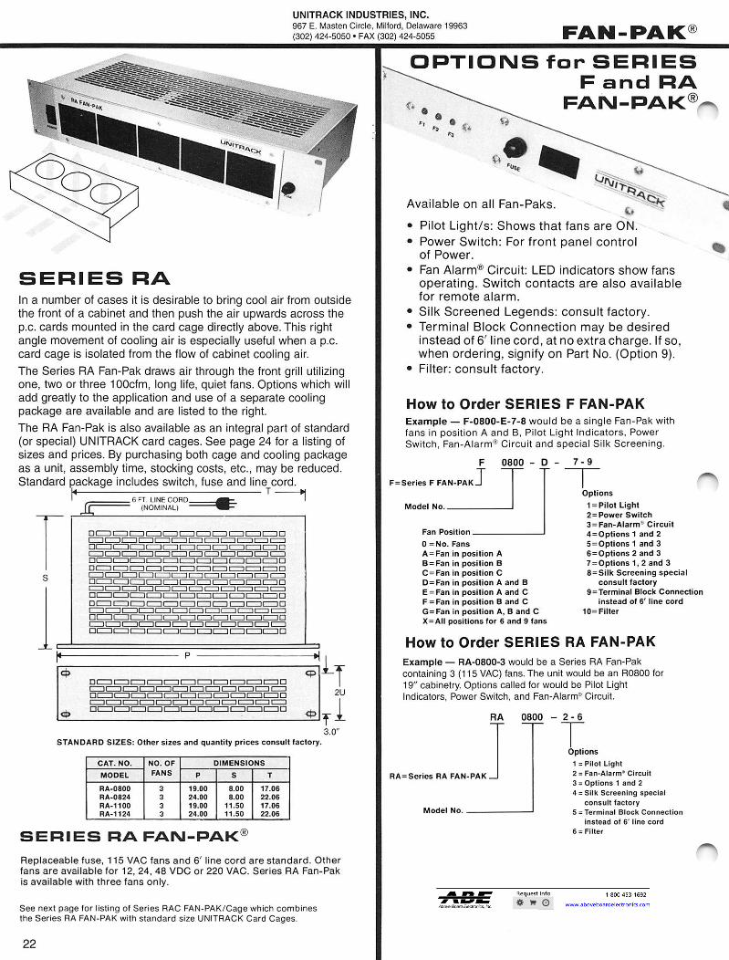
Fan Pak® Series F - bottom entry air 21 Series RA - front panel entry air 22 Options for Series F and RA 22 Series RAC Card Cage with Fan - Pak standard sizes 23
STD 85 Card Files for STD Bus 23
M80 Card File for Multibus* 24
FOR QUANTITY PRICING CONSULT FACTORY We reserve the right to change dimensions or specifications of Unitrack Products.
* Trademark Intel
FEDERAL CODE NO. 07556
Products shown herin are covered by patents and/or pending patent
applications of UNITRACK INDUSTRIES, INC.
© Copyright 1999 UNITRACK INDUSTRIES, INC.
°Registered Trademark UNITRACK INDUSTRIES, INC.
UNITRACKUNITRACK INDUSTRIES, INC.967 E. Masten Circle, Milfbrd, Delaware 19983(302) 424-5050 • FAX(302) 424-5055www.unitracklnd.com
P. C. Card GuidesUNITRACK® vibration and shock damping guides(non - conductive plastic)
UNITRACK® BSD (Electrostatic discharge) vibration andshock damping guides (conductive plastic)
SLOTTED CARD GUIDES (non - conductive plastic)Series 250 (mount on .250 centers) 4Series 300 (mount on .300 centers) 4Series 400 (mount on .400 centers) 5
BSD SLOTTED CARD GUIDES (Electrostatic Discharge)(conductive plastic)Series 250 (mount on .250 centers) 4Series 300 (mount on .300 centers) 4Series 400 (mount on .400 centers) 5
SPECIAL GUIDES
Side Mount 6
Detent guide 6Open Frame card Mounts 6
P. C. Card AccessoriesSeries LIOOO - SS Card Ejectors 7Series L1002 Card Ejectors 7Series L1003 Card Ejectors 7CP300 Card Pull
VersFimount Isolated P. C. MountsVersamount,™ three sizes 8Versamount ADJUST - A - LOCK™ 8
P. C. Metal Card GuidesMetri Guide — Metric card guide 9Ground - R- Guides™ for grounding 10Kooler - Guides™ for heat dissipation 11Series 4700, the card guide for extremely large p.c. cards 12UNPL2008 Aluminum strength with the 13insulation of polycarbonate
P. C. Card Cages ™Subrack90 ADJ™ (adjustable rack) 14, 15 & 16Versa - Cage™ (adjustable rack) 17, 18Subrack90 VME (for VME) 19, 20
Fan Pak®Series F - bottom entry air 21Series RA - front panel entry air 22Options for Series F and RA 22Series RAC Card Cage with Fan - Pak standard sizes 23
STD 85 Card Files for STD Bus 23
MSG Card File for Multibus* 24
PAGE.2, 3
.2, 3
FEDERAL CODE NO. 07556
Products shown herin ore covered
by patents and/or pending patentoppllcations of UNITRA(5k
INDUSTRIES. INC.
Copyright 1999 UNITRACKINDUSTRIES. INC.
Registered Trademark UNITRACKINDUSTRIES. INC.
FOR QUANTITY PRICING CONSULT FACTORYWe reserve the right to change dimensions or specifications of Unltrack Products.
* Trademark Intel

UNITRACK INDUSTRIES, INC. 967 E. Masten Circle, Milford, Delaware 19963 (302) 424-5050 • FAX (302) 424-5055 www.unitrackind.com
UNITRACK®
1-- 1— ..,_7.--.."------- .49
i -\..--_.-------.. f 1,----•_----
W
i .100 .087
.1
.469
80
— — I i
ARAI x ,1
.270 .,••\ N \. V
2.200 T1-1 2.200 Part No 2500-38CH
1 ..
2.500
Part
(with
(with holes
No.
ED5250—CB
ED5250-4CB holes
# for rivets ••)
2500-384CB
for rivets •#')
2.500 Part No. 2500-38
ED5250 # (with integral buttons.)
ED52504 #
Part No. 2500-38A-4
(with integral buttons.)
Part No. SPC3000
. (with EinDte5gra35l °buttli 469
one) ---r--- -\—,--- --"'"
✓
-\`'''''''' \
65
—,
Part No.3 CB 5SPC3000
i
(with
‘...."'"*
el,
holes for rivets ") .185 ...ad Lcc‘1/4N. 1...... LI -4 1406:2
3.000.500 3
Part No. 583040 T--- ED5412 # . (with integral buttons') 469
e,..../.--.\- :
-• •• ----......---
...------..„--
--------
......----._s„...
U
AgrA
116141. .087 _180
IA ' "S 1111W'' PM .‘ Part No. 583040—CB W
.. W
ED5412—CB # 3.625 (with holes for rivets. ") 4.125 —
Part No. RAD4125
W
ED5413 # .472 (with integral buttons')
''----.../-----. -----_,....----
.-.-^--...---
.073
I i I iali .220 -I F Icc\--\\-4. .tcm=J
Part No. RAD4125—CB r7 .... 3.625 ED5413—CB
I 4.125 #
(with holes for rivets. ••)
These card guides are also available in Nylon. Consult Factory. (Since Nylon is affected Dimensions in inches dimensionally by temperature and humidity the dimensions above, given for stable Tolerance: All dimensions under 6" k.010. Over r f .O20. polycarbonate plastic, cannot be used in most applications, a slotted hole rather than round is used to compensate for the 'moving' dimensions.) • Mounting halo Diameter 0.130' (+.003-.000)
recommended metal thickness .050" to .070".
# ESD(Canductiae Plasti) e• Hole Dia. .125+.005-.000, C.B. .290 Dia. .038 deep.
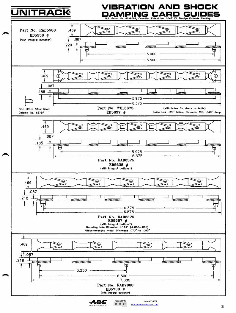
I The patented Unitrack cord guides shown on this page are molded of dimensionally stable polycarbonate or ESD (Electrostatic discharge) plastic. The cantilevered fingers firmly grip the
Zinc plated Rivet p.c. cards and provide excellent vibration and shock damping. When these card guides are Catalog No. RV4700 used in p.c. card cages, the unique design allows free flow of air for cooling of the p.c. except as noted. cards...even in dense packaging applications.
2
FWAHL
SmallO
VIBRATION AND SHOCK DAMPING CARD GUIDES
UNITRACK U.S. Paten No. 4018099, Canadian Patent No. 1042113. Forel n Pattents Pendln
T --_,--- Part No. RAD5500 .469
.,-. --..
--/___-- ----,-..-:--- -
---__-- - ED5550 # I - .----------
(with integral buttons.) .087 (with
.220 L..,zw.. 5.000 5.500
.469 — 0 '): I .087
.185 icccc\-c6-1 ick‘-c4----1 .1<c I 1<(11.11 1 i 5.975
6.375 I
Zinc Catalog
plated Steel Rivet No. 6375R
Part No. ED5637
WEL6375 # Guide
(with holes has .128-
for rivets holes,
or bolts) Diameter C.B. .040" deep.
—f— .469
s.....",. -r- `=. = = =I
•
I .087 i .185 1
I I issm 1 i II { sz______ .-.... .....-.4:, ‘_c_‘‘j -.N.N.,s A Tf- 7. 5.975
6.375 Part No. RAD6375
ED5638 # (with integral buttons.)
—I— k""----_,---..
.469 ---"•-...---"---.. -,-_,,,_, 1
.087 .218
6.375 , - 6.875
Part No. RAD6875 ED5687 #
(with integral buttons.) Mounting hole Diameter 0.191" (+.003-.000)
*Recommended metal thickness .070" to .090"
--._ —l_...---) .469
_,--- r- i .0 7
218 Ric\-----1 \ „ ____I _I f__I
3.250
Ltc\x.-.41,1
I- . 6.500 7.000
Part No. RAD7000 ED5700 #
(with integral buttons.)
3
UNITRACI^VIBRATION AND SHOCKDAMPING CARD GUIDES
U.S. Poten No. 4018099, Conodion Potent No. 1042113, Foreign Pottenta Pending
Part No. RAD5500
ED5550 §(with integral buttons*)
T.469
i1 .087
.220
r~rs^SSSWS
5.000
5.500
♦.469 -
Ir:::^
1 •08'7185 ♦ 1 L̂sNXxji i M
K^^Viu l-mA
rr 1 5.975
6.375
Zinc ploted Steel RivetCatolog No. 6375R
Part No. WEL6375ED5637 #
(with holes for rivets or bolts)Guide has .128' holes, Oiometer C.B. .040" deep.
,185
.469
11087.218
r~f
h
.^SSSSSS\SS\SN1 1 1 1
<S^S51
kSW\SS\^
5.9756.375
Part No. RAD6375
ED5638 #(with integral buttons*)
6.375
6.875
Part No. RAD6875ED5687 #
(with integral buttons*)Mounting hole Diameter 0.191' (+.003-.000)♦Recommended metal thickness .070" to .090"
3.250
6.500 -
• 7.000
Part No. RAD7000
ED5700 #(with integral buttons*)
B
FWAHL
SmallO

UNITRACK INDUSTRIES, INC. 967 E. Masten Circle, Milford, Delaware 19963 (302) 424-5050 • FAX (302) 424-5055 www.unitrackind.com
SERIES 250, 300 Slotted P.C. Card Guide
UNITRACK
Series 250 guides mount on .250 centers. Series 300 guides mount on .300 centers. ...i_ ---..., _.--- 5250-2.5 S300-3.5 W 5250-3
__---- --......, S300-4.25
S250-4 5300-5 n I 5250-6 S300-6 A
5250-7
---.
T k B I
S250-8.5 S300-8 S300-10 W
5300-12.2 ....-- ,..... i Lai 1- • is .125 i
A .150 2 a 1 :
V F ...1
„ --- t
zD TYPICAL SNAP-IN f U u ....)
BUTTON MOUNT I Mounts in .130 hole. Material .050 to .070 thick.
C
B
S300-14 _i_____ ......,_ ---- W ,.-- -----..
I A
_...„
I B
1/16 CARD PART NUMBER
POLYCARBONATE
1/16 CARD PART NUMBER ESD PLASTIC
ADD DASH No. FOR CARD THICKNESS
DIMENSIONS MOUNTING HOLE DIA.
+.002-.001
STYLE MOUNT
METAL THICKNESS
3/32 1/8 A B C D T W
5250-2.5 ED2525 2.50 2.00 .13 .05 .24 .130 2 BUTTONS .050/.070
5250-3 E025313 3.00 2.50 .13 .05 .24 .130 2 BUTTONS .050/.070
S250-4 E02540 4.00 3.50 .13 .05 .24 .130 2 BUTTONS .050/.070
S250-6 E02560 6.00 5.50 .13 .05 .24 .130 2 BUTTONS .050/.070
5250-7 ED2570 7.00 6.50 .13 .05 .24 .130 2 BUTTONS .050/.070
S250-8.5 E02585 8.50 8.00 4.00 .13 .05 .24 .130 3 BUTTONS .050/.070 S300-3.5 ED3350 3.50 3.00 .11 .07 .29 .130 2 BUTTONS .050/.070
5300-4.25 033425 4.25 3.75 .11 .07 .29 .130 2 BUTTONS .050/.070
5300-5 E03500 B 5.00 4.50 .11 .07 .29 .130 2 BUTTONS .0501.070
S300-6 E03600 B C 6.00 5.50 .11 .07 .29 .130 2 BUTTONS .050/.070
5300-8 ED3800 B C 8.00 7.50 3.75 .11 .07 .29 .130 3 BUTTONS .050/.070
5300-10 E03100 B C 10.00 9.00 4.50 .11 .07 .29 .130 3 BUTTONS .050/.070
S300-12.2 E03122 B C 12.20 11.20 5.60 .11 .07 .29 .130 3 BUTTONS .050/.070
5300-14 E03140 14.00 13.50 4.50 .11 .07 .29 .130 4 BUTTONS .050/.070
PRI:13500 ED4350 3.50 3.00 .11 .07 .38 - 2 HOLES -
5583040 E04412 4.125 3.625 .11 .07 .38 .130 2 BUTTONS .050/.070
P806880 E04688 6.875 6.375 .11 .07 .38 .130 2 BUTTONS .050/.070
PR06875 E04687 6.875 6.375 .11 .07 .38 - 2 HOLES -
PRD8500 E04850 8 8.50 8.00 4.00 .11 .07 .38 - 3 HOLES -
DimensIons In Inches Tolerance: All dimensions under 6" ±.0 I O. Over 6" 1.020.
4
FWAHL
SmallO

.045 3.50 ±.015
Series 400 guides mount on .400 centers 1--
S583040 PRD6880
D
b B
.128 PRD6875 PRD3500 0.290
.015
B
.150
t TT kOl T
.125
A
GV2000 Molded Nylon
.075
.2.50
SNAP—IN BUTTON
.135
GV7000 — MOLDED NYLON
7.50
.172 .50 TYP FLAT (3)
r .172
2.50
•-• 2.00
---4 ---------- 4 -------- -
t .047 J
.51=00
(=) .030
250
±.030 .070
•-•—
+.005 —.000
.25 3.50 ±.015
Button mounts in .130 (+.003—.000) dio meter hole in .060 to .070 thick metal. Suggest rear hole/holes be slotted to corn pensate for thermal expansion.
Integral snap—in buttons are designed for quick, easy assembly of guides to the chassis or frame and hold the guide firmly In place.
Series CV mode from molded nylon. .120
A
C
.128 PRD8500
.290
0
.030 TYP
A
UNITRACK INDUSTRIES, INC. 967 E. Masten Circle, Milford, Delaware 19963 (302) 424-5050 • FAX (302) 424-5055 www.unitrackind.com
SERIES 400 Slotted P.C. Card Guide
UNITRACK
5
UIMITRACKUNITRACK INDUSTRIES, INC.967 E. Master) Circle, Milford, Delaware 19963(302) 424-5050 • FAX (302) 424-5055www.unitrackind.com
SERIES 400Slotted P.C. Card Guide
Series 400 guides mount on .400 centers
S583040PRD68B0
25
,150
f
PRD6875PRD3500 0.290
.015
J_
.128 —
290
125 PRD8500
.290
H
-H— 1 1 1 j. ii-r^
T_ c -
n ^
NYLON SLOTTED P.C. CARD GUIDES
GV2000
Molded Nylon
Button mounts in .130 (-i-.003—.000) diometer hole In .060 to .070 thick metol.Suggest rear hole/holes be slotted to compensote for thermal expansion.
Integral snap—in buttons are designedfor quick, easy assembly of guides tothe chassis or frame and hold theguide firmly in place.
SNAP-IN BUTTON
I M
_H K-135Senes GV mode from molded nylon. .120
GV7000 - MOLDED NYLON
i.250
T
£.075
r.i72 ^ z.uu
' .047 ^ li.5C
y
30
f "j ^^ .030 -•Lq
y
7.50 ±.030 .070 +.005-.000
.045 3.50 ±.015
.172
k- .50 TYP FLAT (3)
3.50 ±.015
FWAHL
SmallO

2.500
6.670
SIDE MOUNT GUIDE
DETENT GUIDE A "special" card guide that uses the patented viscoelestic finger method to exert pressure on the edges of the p.c. card. This provides good centering action of the p.c. card as well as firmly holding the p.c. card to damp vibration.
.106 —
DNT6875—B
3.75
.218
.470
2.25
C==1
.078 —1
II II _ 11 In/
6.39
.050
6.375
OPEN FRAME CARD MOUNTS FOR BUS CARDS
1.300
Package one or more Bus Cards in these sturdy, gold iridited aluminum open frame card mounts. units are complete with either 4.525±0.10 22 or 28 position connectors and card guides
To Order: Add —22 to catalog no. for 22 position on .156' centers — solder eye terminal. Add —28 to catalog no. for 28 position on .125' centers — wire wrap pins. Add —0 to catalog no. to indicate without connector.
Card frames are available in multiple heights to suit either STD. WE or other bus types. Consult factory for details. .340
TCF-4565
.250
1.060 4.500 -TYP --t
.750 TYP
.180 .120
SM4535
Material: Polycarbonate .258
Mounting holes: .130 dia. Material thickness limits: .050—.070.
Mount p.c. cards parallel to any surface such as one p.c. card to another p.c. card, p.c. card to a mother board or a p.c. card parallel to a chassis.
4.500 TYP
CARD FRAME
.340 SCF-4565 1.300
2.500
DCF-4565
3.000
.250 TYP
2.400
.078
.140
.300
UNITRACK INDUSTRIES, INC. 967 E. Masten Circle, Milford, Delaware 19963 (302) 424-5050 • FAX (302) 424-5055 www.unitrackind.com
UNITRACK
6
FWAHL
SmallO

How To Order 6 SS
Card =Stainless Steel Thickness
Split Pin ordering=1.1000—S/L
Attach to p.c. card uti izing a split pin or eyelet.
Material: 302 Stainless Steel Finish: Mil Fin.
L1000 Cat. No.
PART No. CARD A 8
Li 000-6—S5 .060 .075 .40
L1000-9-55 .090 .110 .39
L1000-12-55 .0125 .140 .38
SERIES L1002 CARD EJECTORS The Series L1002 card ejectors are small yet provide sufficient leverage to easily remove p.c. cards. Molded of dimensionally stable polycarbonate resin. Ten colors are available (see Table for ordering colors by dash number added to catalog number).
SERIES L1003 CARD EJECTORS Add Dash NO. to Catalog No. to order Color desired
How To Order L1003 — 6 — 2
=Color—Red 6,=,1)716" Board
Split Pin ordering=11000—S/L
.25
20*
.187 R Cat. No.
.25 -11
Attach to P.C. card in standard hole locations (.250 x .250) utilizing a split pin or eyelet.
Molded of dimensionally stable Polycarbon—ate Plastic in colors for circuit identification.
On wide cards two ejectors should be used .100 to more easily insert or extract cards. .265
.290 H
.500
• •
.075 •
.200 -4485
-
—6 Blue —7 Violet —8 Grey —9 White —10 Black
—1 Brown —2 Red —3 Orange —4 Yellow —5 Green
.95 -127 I-- 1 /8''RAD
.41
.312
"*\
.250 —1
A
~iiiii~
~
.6=rto hold 1/16° cord'
.9=to hold 3/32" card Split Pin ordering.--L1000-5/L
How To Order L1002 — X XX
SerieTJ— =Color (See chart for daph number of colors.)
IDENTIFY YOUR CIRCUITRY
WITH COLORS
.200--I
NOTE: RADIUS IS NEEDED ON P.C. CARD
CARD PULL PULL
.080 .250
.200
.39 1.375 1.75
2.36
Fully insulated Plastic Card Pull can be fastened to P.C. boards by riveting or eyeleting.
Card spacing of .300 centers is possible because of narrow width.
Now To Order
Add Dash No. to Cat No.for Color
CP 300 — 2
Color—Red
.290
11-1_
7 .28
L .065
.190 Cat No.
KOLER KODETM CARD EJECTORS & PULL.
UNITRACK
7
UNITRACKTM
& PULL
SERIES L100a-SS CARDLight weight, sturdy metal p.c. cord ejectors withcom lever for both insertion and extraction ofp.c. cards.
.. I1/a RAD 1- 1.20-
iV 1-.345
L6
t
.200 —
11
PART No. CARD A B
L1000-6-SS .060 .075 .40
L1000-9-SS .090 .110 .39
L1000-12-SS .0125 .140 .38
Attach to p.c. cord utilizing a splitpin or eyelet.
Material: 302 Stainless SteelPinish. Mil Fin. how To Order
Li 000 - 6 SSCoL No.—I Cord ^Stainless Steel
Thickness
Split Pin ordering=L1000—S/L
SERIES LIDOS CARD
The Series LI 002 card ejectors are small yetprovide sufficient leverage to easily removep.c. cards. Molded of dimensionally stablepolycarbonate resin. Ten colors are available(see Table for ordering colors by dash numberadded to catalog number).
How To Order
LI 002 - X XX
Senes —1
1/8"RAD
Jd J.6=to hold 1/16" cord
.9=to hold 3/32" cordSplit Pin ordering=L1000—S/L
?:olorSee chart for dash
number of colors.) .200
NOTE: RADIUS IS NEEDED ON P.C. CARD
.250 — —
27
:
I
SERIES LnOOS CARD EJECTORS
iDENTinrYOUR CIRCUITRY
WITH COLORS
Add Dash ND. to Cotalog Noto order Color desired
-1 Brown —6 Blue-2 Red -7 Violet—3 Orange —8 Grey—4 Yellow -9 White—5 Green -10 Block
Molded of dimensionally stable Polycarbonate Plastic in colors for circuit identification.
Attach to P.C. card in standard hole locations(.250 X .250) utilizing a split pin or eyelet.On wide cords two ejectors should be usedto more easily insert or extract cards.
How To Order
LI 003 - 6 - 2
Cat. No—I ~1~ I^Color-Red6=1/16" Board
Split Pin ordering=L1000-S/L
.200
CARD PULL
Fully insulated Plastic Card Pull can befastened to P.C. boards by riveting oreyeleting.
Card spacing of .300 centers is possiblebecause of narrow width.
How To Order
Add Dash No. to Cat No.for Color
CP 300 - 2
Cat NoTZI C^r-Red
2.36
i.200
T"
1.70
T~—I I (
r 1L J
1.375
1.75 -
Q
.250
~r
.39
.290
i LlI I .28
065J
K-.190
FWAHL
SmallO

P .D
SIN
N S
AOP
-0-1 I.- .125
L740-4.1
.200
5.00
.875
L 7-Holes.
.128 ''.ggg DIA.
.188 C'BORE AS SHOWN 4.50
PieD
OO
SSO
Vt i .0
.090
.062_1 1...-41.400
144--
Th-.750
-
10:
.312
.125 _44Cii'6..."IROATNATTII-ON .740 -4.-{ PIN
5.512
VM7600
VM7600 for medium sized p.c. boards use Unitrack card guides: RAD5500 and S-300-5.
Part Number Description
Locks PC card Max. Length
(inches)
VL7500 Includes Versamount VM7500, ADJUST-A-LOCK and hardware (not assembled)
7.50"
VL7600 Includes Versamount VM7600, ADJUST-A-LOCK and hardware (not assembled)
8.95"
VL7800 Includes Versamount VM7800, ADJUST-A-LOCK and hardware
(not assembled)
10.25"
Order card guides separately.
750
200
k-.135
.468
lY
.225 DIA. (2 PLACES)
ADJUST•A•LOCK Part 8 AL7500 used with all three sizes of Versamount.
6-Holes.
.128 +_:ggg DIA.
.188 C'BORE AS SHOWN
2.20 3:625
ANTI-ROTATION PIN
.740
.090
.750
.62511
1.500
1_1 .312
-4-
too,
n0 P
0,3
000
LO
VU
1.4- .250
8-Holes.
- •°°3 DIA.
.188 C'BORE
7.125
3.25
500
500
6.50
550
4.- r„ 8 a, ,"' a Gl ic;
1.90
.150 TYP.
.750
4
io312
062 .125 .090 ANTI-ROTATION
.750 I- .720 -4-, PIN
VM7800
VM7800 for medium size p.c. boards uses Unitrack card guides: RAD7000 and S 300-6.
UNITRACK INDUSTRIES, INC. 967 E. Masten Circle, Milford, Delaware 19963
UNITR AC iC (302) 424-5050 • FAX (302) 424-5055 www.unitrackind.com
VERSAMOUNTTM with ADJUST-A-LOCK'
VERSAMOUNT CARD GUIDE BRACKETS for isolated p.c. card mounting
and ADJUST-A-LOCK adjustable locking feature for Versamount
A pair of Versamounts makes a sturdy, rigid support for mounting of p.c. cards to a chassis or motherboard. Shown here are three sizes of Versamount brackets with molded-in holes to receive various sizes of snap-in Unitrack card guides. Drawings below indicate which card guides fit each size Versamount. Mounting Versamount brackets to a motherboard or chassis requires just two holes for each bracket, one for the anti-rotation pin and the other for a #4 or #6 machine screw to make a rugged, vertical or horizontal support for a p.c. card.
Versamount brackets and Unitrack card
guides are precision molded of durable, tough, dimensionally stable polycarbonate. The ADJUST-A-LOCK can be ordered separately or with the Versamount (see table below).
Assemble the ADJUST-A-LOCK, using the hardware furnished, to the Versamount with the snap-in card guide in place. Slide the p.c. card and seat it in its connector. Lower the ADJUST-A-LOCK units onto the pc card and lock in position by tightening the screws. Remove the card by springing back the card locking member/s, or by loosening the screws. Slide out the p.c. card.
Dimensions in inches. All dimensions under 6" .010.
VM7500
VM7500 for small p.c. boards uses Unitrack card guides: 2500-38, 2500,38-4, SPC3000, RAD4125, PRD-3500 and S 300-3,5.
Versamount holds p.c. card firmly and ADJUST-A- LOCK securely locks p.c. card in place. The ideal combination for isolated board mounting on chassis or motherboard.
8
FOR #6 SCREW
FWAHL
SmallO

STANDARD r
.nm
138mm I— with
spring 9.52mm —.. installed
HEAT SINK
MOUNTING — — 2.79mm
CLIP I — 1.38mm 6.22mm [1.. with
• spring
9.52mm
Left hand guide as viewed from insert end.
6.22mm
2.21mm—
--"."11FZI111111111.... O
SPRING GUIDE INSERT
2mm Lrl
3.8mm METRI—GUIDE (STANDARD)
100MM
120MM
' installed
THE METRI GUIDE Metri—Guide gives you all the Unitrack
quality and advantages in a metric card guide.
Mounting Centers start at 40 millimetters, increasing in 20 millimeters increments.
Standard Guide shown here, available in Heat Sink models see ordering information.
Spring finger insert is available in phosphor
bronze
ORDERING INFORMATION How to order Metri—Guide
Heat Sink Model
KG X X XXXX X
Metri—Gulde j-- i I --LL = Left Handed
Type of plating R = Right Handed Length In millemeters
0—NO FINISH 3—CLEAR ANODIZE (up to 1 meter) 1—CLEAR MITE 4—GOLD ANODIZE bOn 40mm 2=GOLD IRIDITE 5=ELACK ANODIZE 20mm increments
Spring Insert 1. P. = Phosphorus Bronze
Example : MG I P 120 would be an Assembly CLEAR IRIDITE, PHOSPHORUS BRONZE INSERT-100MM LG
with MOUNTING CENTERS 120MM
STUD MOUNTING AVAILAEIL.E. CONSULT FACTORY
Standard
MG X X )0CXX
Metri—Guide Type of plating
ONO FINISH 3—CLEAR ANODIZE 1=CLEAR IRIDITE 4=GOLD ANODIZE 2=GOLD IRIDITE 5=BLACK ANODIZE
—E.L.angth In manometers (up to 1 meter) Min 40mm 20mm increments Spring Insert
1. P. = Phosphorus Bronze
UNITRACK UNITRACK INDUSTRIES, INC. 967 E. Masten Circle, Milford, Delaware 19963 (302) 424-5050 • FAX (302) 424-5055 www.unitrackind.com
9
UIMITRACKUNITRACK INDUSTRIES, INC.967 E. Masten Circle, Milford, Delaware 19963(302) 424-5050 • FAX (302) 424-5055www.unitrackind.com
THE METRI GUIDEMetri—Guide gives you all the Unitrack
quality and advantages in a metric card guideMounting Centers start at 40 millimetters,increasing in 20 millimeters increments.
Standard Guide shownhere, available inHeat Sink modelssee ordering information.
SPRING GUIDE INSERT20mm-^
2mm
I
I
20nn 2,5mm
i2.25mm-
3r33
f3.8mm METRI-GUIDE (STANDARD)
ZD
-1 5nn--
3D ZD
O OC O
•100MM
120MM
Spring finger insertis available in phosphor
bronze
STANDARD
6.22mm j
9.52mm
1.38mm
J withspringinstalled
HEAT SINKI— 2.79mm
MOUNTING
^^.221^m
9.52mm
1.38mm
_l_ with-r- spring' installed
Left hand guideas viewed frominsert end.
ORDERING INFORMATION
Molri-Guide
Type of platingO-NO RNISH 3-CLEAR ANODIZE1=CLEAR IRIDITE 4=G0LD ANODIZE2=G0LD IRIDITE 5=BLACK ANODIZE
MG
.J
Stondord
X X XXXX
How to order Metri—Guide
^ngth In mtllamaters(up to 1 meter)Min 40mm20mm incremente
' Spring Insert1. P. = Phosphorus Bronze
Matrl-Gulde-
Type of plating0-NO FINISH 3-CLEAR ANODIZE1-CLEAR IRIDfTE 4-GOLD ANODIZEZsGOLD IRIDITE SaBLACK ANODIZE
Example : MG J_P 120 would be an AssemblyCLEAR IRIDITE, PHOSPHORUS BRONZE INSERT-100MM LG
wHh MOUNTING CENTERS 120MM
STUD MOUNTING AVAILABLE. CONSULT FACTORY
Heat Sink Model
KG X
JXXXX_ X
T_L = Left HandedR = Right Handed
txngth In mlllemeters(up to 1 meter)Min 40mm20mm Increments
- Spring Insert1. P. s: Phosphorus Bronze
FWAHL
SmallO

.156
.125
t A__
f I I 1 -1- .150
.015 .095
ORDERING INFORMATION
.00' 0•0" 000r
I..-- 6.000
6.375
TRACK STYLE GROUND-R-GUIDE FURNISHED WITH MOUNTING CLIPS AS STANDARD
3/16"
11OLE 3/16" +.125/.128
°MEM MOUNTING CLIP
CATALOG No. MC1000 HOLES
OPTIONAL MOUNTING METHODS
STUD IfOUNTING
4-40 SS STUD I 1/4" LONG
U N IT R AC UNITRACK INDUSTRIES, INC.
e 967 E. Masten Circle, Milford, Delaware 19963 (302) 424-5050 • FAX (302) 424-5055 www.unitrackind.com
TM GROUND—R—GUIDE The Grounding Card Guide
OPEN STYLE The Ground—R—Guide, with spring finger action found only in UNITRACK card guides offers exceptional grounding features. The OPEN STYLE Ground—R—Guide can be mounted to a chassis or motherboard with rivets, using the holes provided in the
guide. Ground—R—Guide is available in three metals: phosphor bronze, stainless steel and beryllium copper.
FEATURES * The firm grip afforded by the
spring fingers develops a useful pressure contact over the length
of the p.c. cord for excellent electrical current passage.
* Large contact area of spring fingers provides a stable ground potential.
HOW TO ORDER
XX 1000 - XXX
Length in inches (in 1/2 in increments in sizes to 36 inches.)
Semi—hollow Aluminum Rivet
Catalogue No.1000R
TRACK STYLE
The TRACK STYLE Ground—R—Guide affords grounding for p.c. boards with the patented spring finger action found only in UNITRACK card guides. GB1008
Metal: PB=Phosphor Bronze BC-Beryllium Copper SS=Stainless Steel
Series
* TRACK STYLE Ground-R-Guide available for spanning open spaces. See below. Spring fingers give good shock and vibration damping.
* Available to exact lengths to customer specifications or in long lengths for customer cutting.
* Special assemblies also available.
FEATURES * Pressure developed by spring
fingers provides contact over entire length of p.c. card for excellent electrical current passage.
* Aluminum extrusion provides *
Metal: PB=Phosphor Bronze BC=Beryllium Copper SS=Stainless Steel
UN
Series J
rigid guide for spanning open areas (often required for air circulation or cooling). Available to hold 1/1 6" thru 1/8" p.c. cards. Spring fingers provide shock and vibration damping.
MOUNTING: (optional) H-Guide Bar with holes S=Guide Bar with studs
Length in inches (in 1/2 in increments in sizes to 36 inches.)
STANDARD SPACING OF AND STUDS
Guides up to 6 inches long-2 holes, or 2 studs spaced 1/2" from each end of the guide. Guides up to 10 inches long-3 holes, or 3 studs evenly spaced with the end holes or hardware 1/2" from each end of the guide. Guides over 10 inches long-4 holes, or 4 studs evenly spaced with the end holes or hardware 1/2" from each end of the guide. Longer guides, consult factory. Holes not available with Berylium Copper.
* Special placement (other than standard),consult factory
.173
.245 .045
1—.375
T
HOW TO ORDER xx
1008 - xx.x x
Type of Plating: 1 = Clear indite 2 = Gold indite 3 = Clear Anodize 4 = Gold Anodize 5 = Black Anodize
Example: UNSS1008-6 would be an assembled unit of: 6" long GB1008 Guide Bar; one 5.5" long SS1000 Stainless Steel card guide and two MC1000 mounting clips. Mounting hole centers would be 6.375 inches.
10
FWAHL
SmallO

Thermal characteristics for two 6 inch long KOOLER-GUIDES type
KGPB375-6 holding an aluminium test card .060" thick x 4.5" wide x 6" long.
90
70
60
50
40
30
Tests prove the positive heat dissipating ability of the Kooler-Guide. The unique spring fingered configuration firmly pressing the P.C. card against the guide enables the heat to be more effectively reduced.
9 The solution to densely packaged
heat producing products.
The various mounting methods available increase the versatility of the Kooler-Guides.
.050
STANDARD SERIES KG375 Kooler-Guide with mounting clips hole dia. (±.003) .128
SERIES KG375-S Kooler-Guide with 4-40 X 1/4" long threaded S.S. Studs
.150—s1.120
.240
HOW TO ORDER
KG XX 375 - XX.X XX X
Kooler Guide
Metal: PB = Phosphor Bronze BC = Beryllium Copper SS = Stainless Steel
Series
Test Point B fi
.240
. Test Aluminium t Point A Test Card
Kooler Guide PB 1000 Insert
Kooler Guide
Metal: PB = Phosphor Bronze BC = Beryllium Copper
Card Insertion SS = Stainless Steel
Right Heat Sink
Tab Heat Sink
Tab Left
UNITRACK INDUSTRIES, INC. 967 E. Masten Circle, Milford, Delaware 19963
UNITRACK (302) 424-5050 • FAX (302) 424-5055 www.unitrackind.com
KOOLER-GUIDEP" U.S.Patent No. 4,096,547
UNITRACK'S KOOLER-GUIDE acts as a heat sink to effectively dissipate heat from "Hot" printed circuit cards. Metal fingers press the P.C. card into intimate contact with the guide bar over its entire length. This large contact area transfers the heat rapidly from the P.C. card to the Kooler-Guide and into the chassis or cold frame holding the guide.
Kooler-Guide is designed for P.C. cards .040" to .095" thick. The various mounting methods avail-able make the Kooler-Guide useful for almost any packaging or heat dissipation requirement.
-. TEMP. RISE OF KOOLER GUIDE AT POINT "R-- WITH C
I
RD IN KOOLER GUIDE
10 20 30 40 WATTS
LEFT HAND GUIDE VIEWED FROM INSERTION END
Heat Source
/ COLD FRAME AT AMBIENT TEMPERATURE
S = Stud Mounting (Optional)
L = Left handed R = Right handed
_Length in inches in V2 inch increments.
Type of Plating: 1 = Clear Iridite 2 = Gold Iridite 3 = Clear Anodize 4 = Gold Anodize 5 = Black Anodize
The Kooler-Guide insert is available in your choice of the following:
• PHOSPHOR BRONZE (PB) • STAINLESS STEEL (SS) • BERYLLIUM COPPER (BC)
Standard spacing of holes, studs or swage nuts.
• Guides up to 6 inches long - 2 holes, 2 studs or 2 swage nuts spaced 1/2" from each end of the guide.
• Guides up to 10 inches long - 3 holes, 3 studs or 3 swage nuts evenly spaced with the end holes or hardware 1/2" from each end of the guide.
• Guides over 10 inches long - 4 holes, 4 studs or 4 swage nuts evenly spaced with the end holes or hardware 1/2" from each end of the guide.
• Holes not available in Beryllium Copper for series 375.
Dimensions in inches. Tolerance: All dimensions under 6" • .010: over 6" • .020.
SERIES KG690-H Kooler-Guide mounting flange with .136 dia. holes.
SERIES KG690-N Kooler-Guide mounting flange with 4-40 threaded swage nuts.
.4— .375 —li .690
Card Insertion
Series TO ORDER RIGHT OR LEFT HAND GUIDES -
Add letter to end of catalog number, L=Left, R =Right. When viewed from the entry end, the heat sink tab signifies right or left.
HOW TO ORDER
XX.X Type of Plating:
1 = Clear Iridite 2 = Gold Iridite 3 = Clear Anodize 4 = Gold Anodize 5 = Black Anodize
11
L = Left handed R = Right handed
—Length in inches in V, inch increments.
H = Mounting Flange with holes
N = Mounting Flange with swage nuts
UIMITRACK
UNITRACK INDUSTRIES, INC.967 E. Masten Circle, Milford, Delaware 19963(302) 424-5050 • FAX (302) 424-5055www,unitrackind.com
KOOLER-GUIDEU.S.Patent No. 4,096,547
UNITRACK'S KOOLER-GUIDE acts as a heat sinkto effectively dissipate heat from "Hot" printedcircuit cards. Metal fingers press the P.C. cardinto intimate contact with the guide bar over itsentire length. This large contact area transfersthe heat rapidly from the P.C. card to the Kooler-Guide and into the chassis or cold frame holdingthe guide.
Kooler-Guide is designed for P.C. cards .040" to.095" thick. The various mounting methods available make the Kooler-Guide useful for almostany packaging or heat dissipation requirement.
Thermal characteristics for two 6 inch long KOOLER-GUIOES type
KGPB375-6 holding an aluminium test card .060" thick x 4.5" wide x6" long.
Tests prove the positive heat dissipating ability of the Kooler-Guide. The unique springfingered configuration firmly pressing the P.C. card against the guide enables the heatto be more effectively reduced.
The solution to densely packagedheat producing products.
- -
The various mounting methods availabie Increase the versatility of the Kooler-Guides.
-I—
•H
LEFT HAMD CUlOE VIEWEDFROM INSERTION END
STANDARD
SERIESKG375Kooler-Guide
with mounting clipshole dia. (±.003) .128
SERIES
KG375-SKooler-Guide
with 4-40 X Va"longthreaded S.S. Studs
. Tc«tf Point A '
. AiuminkumTe«t Cord HOW TO ORDER
COLD FRAME AT AMBIENT TEMPERATURE
The Kooler-Guide insert is available inyour choice of the following:
• PHOSPHOR BRONZE (PB)• STAINLESS STEEL (88)• BERYLLIUM COPPER (BC)
Standard spacing of holes, studs or swage nuts.
• Guides up to 6 inches long - 2 holes, 2 studs or 2 swagenuts spaced V?" from each end of the guide.
• Guides up toiO inches long-3 holes, 3 studs or 3 swagenuts evenly spaced with the end holes or hardware Vz"from each end of the guide.
• Guides overlO inches long - 4 holes, 4 studs or 4 swagenuts evenly spaced with the end holes or hardware Vz"from each end of the guide.
• Holes not available in Beryllium Copper for series 375.
Dimensions in incnes.
Tolerance: All dimensions under
6' • .010: over 6" - .020.
Kooler Guide
Metal:PB s Phosphor BronzeBC = Berylllum CopperSS = Stainless Steel
U-1/2"
SERIES
KG690-HKooler-Guide
mounting flange with.136 dia. holes.
I S = Stud Mounting(Optional)
L= Left handedR = Right handed
.Type of Plating:1 = Clear Irfdite2 = Gold Iridite3 = Clear Anodize
4 = Gold Anodize
5 = Black Anodize
Length in inchesin 'A Inch increments.
SERIES
KG690-NKooler-Guide
mounting flangewith 4-40 threaded
swage nuts.
Heat Sink
Tab
Heat Sink
Tab HOW TO ORDER
IL
TO ORDER RIGHT OR LEFT HAND GUIDES -
Add letter to end of catalog number, L=Left, R = Right.When viewed from the entry end, the heatsink tab signifies right or left.
Kooler Guide
Metal:PB = Phosphor BronzeBC = Beryllium CopperSS = Stainless Steel
Type of Plating:Mounting Flange 1 = Clear Iriditewith holes 2 = Gold Iriditewith holes 2 = Gold Indite
N= Mounting Flange 3 s Clear Anodizewith swage nuts 4 = Gold Anodize
I—L = Left handedR = Right handed
Length in inchesin A inch Increments.
5 = Black Anodize
FWAHL
SmallO

UNITRACK SERIES 4700 U.S Patent 3.950.057
SERIES 4700
The Series 4700 UNITRACK Card Guides incorporate the patented* spring finger action of UNITRACK Card Guides to accommodate p.c. cards up to 6' long! Now "big" boards can be held with the card guide that provides vibration and shock damping for p.c. cards 1/16" to 1/8" thick. Dimensionally stable polycarbonate plastic segments are simply slid into the guide bar to make any length card guide needed. Mounting clips lock the segments within the guide bar, as well as provide a positive mounting method. Other special mounting arrangements are available, such as bonding, rivet-ing, etc.
Series 4700 UNITRACK Card Guides are available as assemblies to exact lengths or as individual parts to be assembled by the customer. Although many large p.c. cards are mounted to a solid chassis, the rigid guide bar makes it possible to easily span open spaces.
I
Segments slide into guide bar to make any length card guide.
OPTIONAL MOUNTING METHODS Guide bar with flange and mounting holes. Also available but not shown is guide bar with flange and swage nuts.
Spring finger segment of polycarbonate.
/ .230
Mounting clips lock in segments and provide mount-ing holes at each end.
.255 r G-
300 060
J-1
,-- 495
Guide Bar GB4718 Recommended for board thickness .060"-.140"
125 128 dia
— F- 11 385
- 190 1/4" to start of first segment — .375 --
Mounting Clip Cat. No. MC4700
Part Cat. No.
8" Segment SG4700-8
NOTE: Length of Guide bar is 1/2" longer than Dash No. Mounting hole dimensions are .875" longer than Dash No.
Example: UN4718-14 would be an assembled unit of: One GB4718 fourteen and one half inches long, SG4700 segments and two MC4700 mounting clips. Mounting hole dimensions would be 14.875 inches.
Mounting Clip
MC4700
Dash Mounting No. Hole Centers
Standard spacing of holes, studs or swage nuts.
• Guides up to 6 inches long - 2 holes, 2 studs or 2 swage nuts spaced '/2" from each end of the guide.
• Guides up to 10 inches long - 3 holes, 3 studs or 3 swage nuts evenly spaced with the end holes or hardware 1/2" from each end of the guide.
• Guides over 10 inches long - 4 holes, 4 studs or 4 swage nuts evenly spaced with the end holes or hardware 1/2" from each end of the guide.
TO ORDER RIGHT OR LEFT HAND GUIDES - Add letter to end of catalog number, L=Left, R=Right.
Basic Cat. No.
Snap-in Rivet RV4700
Guide Bar GB4718
Guide bar with flange FL4718
Specify Left or Right
Dash OPTIONS FOR No. UNFL4718
Basic Cat. No.
.255 r
E 300 .060
I S .
—77-7 ,-- .495 ---- .495
Guide Bar FL4718 Guide bar with flange (Specify holes -H or flange nuts -N) Recommended for board thickness .060‘" - .140"
-H = Holes -N = Swage Nuts -L = Left -R = Right
UN4718 UNFL4718
Dimensions in incnes. Tolerance: All dimensions under 6' -t.010: over 6" .020.
12
-6
6.875" -8
8.875" -10
10.875" -12
12.875" -14
14.875" -16
16.875" -18
18.875" -20
20.875"
-6 - 8 -10 -12 -14 -16 -18 -20
FWAHL
SmallO

X
.110 INSERT I .
1095
4 - 40 STUD X 1/4"
UN PL
SERIES-
PLASTICS
INSERT
END
VIEW
.187- —.375
X+.375
X
UNPL2008 WITH STUDS OR WITH CLIPS Aluminum strength with the insulation of polycarbonate available with studs or clips, for ease of installation, studs can be placed to suit your cage.
ORDERING INFORMATION
h7— —7-0.50 --1-1
0.375 C •
CLIPS
AS REQ.
INSERTS (LINERS) P2000
X x
MOUNTING: (optional) C=Clips S=Guide Bar with studs
LENGTH IN INCHES (to 36 inches)
Example: UNPL2008-6 would be an assembled unit of: 6" long GB1008 Guide Bar; one 5.5" long PLASTIC INSERT and two MC1000 mounting clips. Mounting hole centers would be 6.375 inches.
STANDARD SPACING OF CLIPS AND STUDS
Guides up to 6 inches long-2 clips, or 2 studs spaced 1/2" from each end of the guide. Guides up to 10 inches long-2 clips, or 3 studs evenly spaced with the end holes or hardware 1/2" from each end of the guide. Guides over 10 inches long-2 clips, or 4 studs evenly spaced with the end studs or hardware 1/2" from each end of the guide. Longer guides, consult factory.
STUDS
HOW TO ORDER 2008 - XX.X
TYPE OF PLATING 1-Clear Iriclite 2-Gold Iridite 3-Clear Anodize 4-Gold Anodize 5-Black Anodize
* Special placement (other than standarcaconstat factory
13
UNPL2008WITH STUDS OR WITH CLIPSAluminum strength with theinsulation of polycorbonateavailable with studs or
clips, for ease ofinstallation, studscon be placedto suit yourcage.
ORDERING INFORMATION
INSERT-| |- .110
J^-095HOW TO ORDER
PL 2008 - XX.X
END
VIEW
.187-
0.375 iSL
4-40 STUD X 1/4"
-.375
STUDS
X+.375
CLIPS
AS REQ.
INSERTS (LINERS)P[2000
SERi
PLASTICS
INSERT
UN X
TX
11-MOUNTING: (optional)C=CiipsS=6utde Bar wrth studs
— LENGTH IN INCHES(to 36 inches)
-TYPE OF PLATING1-Clear Irldlte
2-Gold Indite3-Cl8ar Anodize
4-Gold Anodize5-Black Anodize
Example: UNPL2008-6 would be anassembled unit of: 6" long GB1008Guide Bar; one 5.5" long PLASTICINSERT and two MC1000 mountingclips. Mounting hole centers wouldbe 6.375 inches.
STANDARD SPACING OF CUPS
AND STUDSGuides up to 6 inches long-2 clips, or 2 studsspaced 1/2" from each end of the guide.Guides up to 10 inches long-2 clips, or 3 studsevenly spaced with the end holes or hardware 1/2"from eoch end of the guide.Guides over 10 inches long-2 clips, or 4 studsevenly spaced with the end studs or hardware 1/2'from each end of the guide.Longer guides, consult factory.
:4c Special placeTnejit (other than standard),consult factory
13
FWAHL
SmallO

•
•••••., *•••:
e'47 '74(1
Example: Subrack90 Model ADJ to hold 21 p.c. cards (on .8 centers).
HOW TO ORDER 90 ADJ A 3 2 4250
TConnector Bar Spacer Length Dimension - Figures represent center-to-center mounting hole dimension of connector (or mother board). In this example 4250 (41/4").
Series Depth of End Plate (A=8") Height of End Plate (3=3U)
Hole Pitch .200 (2= 200)
IJ
UNITRACK INDUSTRIES, INC. 967 E. Masten Circle, Milford, Delaware 19963 (302) 424-5050 • FAX (302) 424-5055 www.unitrackind.com
UNITRACK SUBRACK 90 ADJ
MOUNTING FLANGE
••••-•
• s'
SUBRACK90 MODEL ADJ Adjustable Series An extremely versatile card rack with total flexibility for adjustment. The bars are sturdy and when assembled the Subrack90 Model ADJ is a very rigid rack that fits into 19" cabinetry or can be used as a stand-alone rack. The rack is attractively clear iridited.
SUBRACK90 MODEL ADJ VERSATILE... ADJUSTABLE - lets you package
both large and small P.C. Cards!
EXTRACTOR BAR
CARD GUIDES
SUPPORT BAR
END PLATE
CONNECTOR N'••, .
BAR
CONNECTOR BAR SPACER
14
Standard single high Subrack90 Model ADJ consists of the following parts:
2 Extractor Bars 2 Support Bars (11.5" deep cages
may use 4 Support Bars) 2 Connector Bars 2 Connector Bar Spacers 2 End Plates 2 Mounting Flanges Required Hardware
Order card guides separately.
Card racks are normally shipped unassembled.
STANDARD SUBRACK 90 MODEL ADJ SIZES LISTED BY P.C. CARD SIZE
Card Size (Depth)
Heigh Recommended Card Guides "U" Panel
Units (Inches)
3.5"-4.5" High up to 7" Long 3U 5.22 4.5"-6" High up to 7" Long 4U 6.97 6"-7.75" High up to 7" Long SU 8.72 6300-3-5 7.75"-9.5" High up to 7" Long 6U 10.47 S300-4 9.5"-11.25" High up to 7" Long 7U 12.22 S300.5 or -5B 11.25"-13" High up to 7" Long 8U 13.97 S300-6 or -6B or -BC 13"-14" High up to 7" Long 9U 15.72 S300-8 or -8B or -SC
3.5"-4.5" High up to 10.5" Long 3U 5.22 GV7000 (nylon)
4.5"-6" High up to 10.5" Long 4U 6.97 See Catalog 6"-7.75" High up to 10.5" Long 5U 8.72 pages 14 to 16 7.75"-9.5" High up to 10.5" Long 6U 10.47 for details of 9.5"-11.25" High up to 10.5" Long 7U 12.22 card guides. 11.25"-13" High up to 10.5" Long 8U 13.97 13"-14" High up to 10.5" Long 9U 15.72
Height of END Plate (1U = 1.750 inches)
3=3U 4=4U 5=5U S=EW 7=7U 8=8U 9=9U
Connector Bar Spacer Length indicate in inches the distance between mounting hole centers of connectors being used or mother board mounting holes. Example: Mother board mounting holes are 4.06 (center to center). Last four digits would be 4060.
Hole Pitch 2=.200" 4=.250"
All dimensions in inches.
HOW TO ORDER A 19" SUBRACK90 MODEL ADJ 90 ADJ X X X XxXX
Series Number for Subrack90 ADJ J standard 19" card cage for 19" cabinets
Depth of End Plate
A = 8.00" B = 11.5"
FWAHL
SmallO

Connector Bar Designator
HOW TO ORDER 90 ADJ CB XXXX X
—Hole Pitch Series 2=.200
T-
4=.250
Length of Bar Standard Length = 17.00"
"(Example: If half bar XXXX would become 0850
Holes for 8-32 self tapping screws -2 each end. HOW TO ORDER
90 ADJ EB XXXX X
Series — IT 2=.200 T_Hole Pilch
4=.250
Holes for 8-32 self tapping screws -2 each end.
1 00 1 30
HOW TO ORDER 90 ADJ HB XXXX X -c_.Hole Pitch
Series 4 =.250 2=.200
Length of Bar Standard Length = 17.00"
"(Example: H half bar XXXX would become 0850
.455 .455 END PLATES
HOW TO ORDER 90 ADJ END PL X X
Dual Row
Series End Plate Designator
CONNECTOR BAR SPACER
8-32 TAP I 2 places /
- •••,4c- - .5001
\ 6-32 TAP
See "HOW TO ORDER" to 2 places specify this dimension
HOW TO ORDER 90 ADJ CBS XXXX
—Length of Spacer Bar Connector Bar NOTE: Length is determined from Spacer Designator center to center of holes to mount
connectors or mother board. EXAMPLE: Connector mounting holes are 4.875" center to center. Last 4 digits would be 4675.
CONNECTOR BAR
!Ts.- .130 Dia. Mounting holes CL on .200 or .250 for length of bar
I
EXTRACTOR BAR .130 Dia. Holes on .200 or .250 centers for length of bar
H, .250
El [-- I
1.48-.560-4.1
-81 .130
T .3;5
.75 -11- Mounting Hole 8-32 TAP • 2 places_ .
MOUNTING FLANGES
--pi 1.49 rs-- 1.49
0 = = 4 — -
"1"T T —
co) • 9
110_ End Plate
F .300
L
ength of Bar Standard Length = 17.00"
"(Example: If half bar XXXX would become 0850
2 Slots .406 x .281
tw--
i t
.90 1.09
Extractor Bar Designator
SUPPORT BAR
HOW 90 ADJ
Series Mounting Flange Designator
Panel Height In U Units: 3=3U 4=4U 5=5U 6=6U 7=7U 8=8U 9=9U
-I— Number of mounting slots
1=standard (see dimensions on drawing)
2=special number of slots or special position for slots (customer to supply drawing)
.130 Dia. Holes on .200 or .250 centers for length of bar
.28
I
TO ORDER MTG FL X X
Support Bar Designator
Single Row
Panel Height in U units 3=3U 7=7U 4=4U 8=8U 5=5U 9=9U 6=6U
Depth of End Plate A=8.00" B =11.5"
- -F-,---•--- 4) - - e"41. --.--+ tort 6.3: = = = 0 = = = -G---, cry 0 = .-, 0 .-i = = 0 C , 0 = = = = ,.. = 0 C , 0 = =
= C- 3 C-- 3 0 0 c_ _ ., = r_ = ,..--.-_-, _, A .•-• 8' B = 11.50"
= = = = OTS
50 r_ r- -, = = r = when assembled with mounting = o0 0 0 = = .--=, r__, r , 0 = = = r . -) C 3 flange I=3 0 0 1 0 r -3 0 0 0 , 0
0 I. ____, I ' , 3 C -, 0 C -/ r =3 0
(=> 0 0 , 0 0 0 I C_- -, C---/ ,' 0 0 0 0 j I G---3 0 I. 0 I 0 I 0 i 0 1 I 1 „_e___. 0 -0. —
' I ? i—c__, ., III- f___3- , TT— • I .455 i -per
I I I 1 - a 3, 4, 52U Units 6 U Units and Lip .._
Mounting holes b unting Flange Thread
S
Slots for mountin connector spacer
UNITRACK INDUSTRIES, INC. 967 E. Masten (302) 424-5050
C(rcleFAX 3i02)) 424-5 De5055
laware 19963 S U B RAC K 90 ADJ (Parts) UNITRACK® HOW TO ORDER INDIVIDUAL PARTS FOR SUBRACK90 MODEL ADJ
Dimensions M inches. 15
UIMITRACK'
UNITRACK INDUSTRIES, INC.967 E. Masten Circle, Milford, Delaware 19963(302) 424-5050 • FAX(302) 424-5055 SUBRACK 90 ADJ (parts)
HOW TO ORDER INDIVIDUAL PARTS FOR SUBRACK90 MODEL ADJ
CONNECTOR BAR SPACER
8-32 TAP
2 places
6-32 TAP
See "HOW TO ORDER" tospecify this dimension
2 places
HOW TO ORDER
SO ADJ CBS XXXX
Series-
Connector BarSpacer Designator
MOUNTING FLANGES
»| 1.49 j-«—
X Length of Spacer Bar
NOTE; Length is determined fromcenter to center of holes to mountconnectors or mother Iward.
EXAIMPLE: Connector mountingholes are 4.67S" center to center.Last 4 digits would be 4675.
2 Slots .406 X .281
I I EndI I Plate
HOW TO ORDER
90 ADJ MTG PL X X
Series-
Mounting Flange.Designator
Panel Height in U Units; —3=3U
4°4U
5=5U
6=6U
7 = 7U
8=eu
9=3U
END PLATES
SLOTS
IS) .50
Slots for mounting —connector spacer bar
/
I . Numlier of
mounting slots
1 =standard (see dimensionson drawing)
2-special number of slotsor special position forsiots (customer to supplydrawing)
. 6 U Units and Up
Dual Row
CONNECTOR BAR .560-k.|
Mounting Hole6-32 TAP • 2 places^.
.375
1.
.130
— .130 Dia. Mounting holes9. on .200or .250forlengthofbar
HOW TO ORDER
90 ADJ CB XXXX X
JSeries
Connector BarDesignator
T—Hole Pitch2=.200
4=: .250
—Length of BarStandard Length = 17.00"
'(Example; If half barXXXX would become 0850
EXTRACTOR BAR
.300
.23
Series_
Extractor Bar.Designator
.130 DIa. Holes on .200 or
.250 centers for length of bar
100
- 1.60
HOW TO ORDERHOW TO ORDER
90 ADJ EB XXXX X
\ Holes for 8-32 selflapping screws —2 each end.
.Hole Pitch
2=.2C0
4=.250
JLength of BarStandard Length = 17.00"
'(Example; If half barXXXX would become 0850
SUPPORT BAR
A = 8B = 11.50
when assembled
with mountingflange
.130 Dia. Holes on .200 or
.250 centers for length of bar
Nk I »M.130t.
HOW TO ORDER
90 ADJ HB XXXX X
Holes for 8-32 selftapping screws —2 each end.
. Hole Pitch2=.200
4=.2S0
-Length of BarStandard Length
'(Example; If half bar
Series.
Support Bar.Designator
3, 4. 5 U Units •
Single Row
17.00"
Mounting holesfor Mounting Range6-32 Thread
HOW TO ORDER
90 ADJ END PL X X
Dimensions in inches.
Series
End Plate
Designator
-Panel Height in U units3=3U 7=7U
4=4U 8=8U5=5U 9=9U
6=6U
- Depth of End Plate A=8.00"B=11.5"
15
FWAHL
SmallO

CONNECTOR BAR
CONNECTOR SPACER
CARD GUI DES
SUPPORT BAR
END PLATE
Substitute 2 PANEL BARS for EXTRACTOR BARS. For help in making PANELS to suit —CONSULT FACTORY.
PANEL BAR WITH TAPPED BAR
Panel Bar
For ordering information of cage see page 6 & 7 of Catalog.
ADJS4000
.530
PANEL BAR .130
Holes for 8-32 self tapping screw 2 ea. end
HOW TO ORDER
Panel Bar Designator L Length of Bar
Standard Length=17.00'
.292
XXXX X
Hale Pitch 2=.200
90 ADJ PB
Series
Tapped Bars
Tapped Bar ordered separately.
Hole For Retainer Sleeve
A
RETAINER SLEEVES CAPTIVE SCREWS ADJR3050
.280 -•—.240 .213
.270
T 1.17123
SUPPORT BRACKETS ADJB2000
—1 .340 iT
.210 01.300 f 1 .170
; .475.645
II .312
ORDERED SEPARATELY ORDERED SEPARATELY
UNITRACK INDUSTRIES, INC. 967 E. Masten Circle, Milford, Delaware 19963 (302) 424-5050 • FAX (302) 424-5055 www.unitrackind.com
UNITRACK
SUBRACK 90 MODEL AIN CUSTOMIZE WITH FRONT PANELS
PANEL MOUNTI NG PANEL
FLANGE BAR
16
FWAHL
SmallO

DASH STYLE OF MOUNTING
- F - R - S
FRONT REAR SIDE
CONNECIIOR BAR
VERSA-CAGE TM
Rugged Assemblies or Parts
VERSA-CAGE CARD RACKS are strong, sturdy, low cost and easy to assemble. Standard sizes conforn to electronic industry standards. End plates, holder bars and connector bars are accurately punched to close dimensional tolerance.
END,Pait
1. HOLDER BARS: Sturdy extrusions accurately prepunched on .200 8c .250 centers for total versatility in card spacing 2. CONNECTOR BARS: An extrusion prepunched to perfectly align connectors with P.0 cords in card guides. 3. CONNECTOR BAR MOUNTING BRACKETS: Connectors can be mounted then pre-wired. Entire assembly can be inserted in cage.
CARD GUIDES SEE tATIE BELOW
4. ANGLE BRACKETS: Perfectly align and firmly lock bars to end plates. Two 8-32 bolts are provided for assembly with tapped holes in angle brackets.
5. CARD GUIDES: Patented UNITRACK cord guides just snap into pre punched holes in bars. P.C.Cards are gripped between fingers to provide anti-vibration and shock damping. Open design of UNITRACK Card guides allows free flow of air for cooling P.C. Cards.
6. EXTRACTOR BAR: When used with KOLOR-KODE CARD EJECTORS. makes insertion or extraction of P.C. cards almost effortless.
EXTRAC1'OR BAR OR
HOLDER BAR
AM706
•••••••,.
a. V
STANDARD VERSA-CAGE SIZES: Catalog numbers listed below do not include card guides. These should be ordered separately. Versa-Cage card racks ore normally shipped unassembled. Consult factory for prices on assembled cages.
Note: Add dash number to the Versa-Cage catalog number for the features from the table below. Also specify the Connector Bar Mounting Bracket desired.
CARD SIZE "U"
PANEL UNITS
PANEL HEIGHT
CATALOG NUMBER
DASH NO.
RECOMMENDED GUIDE
3.5"-4.5" High up to 6.5" Long 3U 5.22 VC*119-450- # S300-3.5 4.5"-6" High up to 6.5" Long 4U 6.97 VC*119-625- or 6"-7.75" High up to 6.5 Long 5U 8.72 VC*119-800- SPC3000 7.75"-9.5" High up to 6.5" Long 6U 10.47 VC*119-975- RAD4125 9.5"-11.25" High up to 6.5" Long 7U 12.22 VC*119-1100- 58-30-40 11.25"-13" High up to 6.5" Long 8U 13.97 VC*119-1200- or
S583040
4.25"-5.25" High up to 6" Long 4U 6.00 VC*1706- 58-30-40 3.5"-4.5" High up to 6" Long 3U 5.22 VC*1705- or
S583040
3.5"-4.5" High up to 9.25" Long 3U 5.22 VC*219 -450 - 4.5"-6" High up to 9.25" Long 6"-7.75" High up to 9.25" Long
4U 5U
6.97 8.72
VC*219-625- VC*219-800- 1 WEL6375S300-6
7.75.-9.5 High up to 9.25" Long 6U 10.47 VC*219-975- RAD7000 9.5"-11.25" High up to 9.25" Long 7U 12.22 VC*219-1100- i 11.25"-13" High up to 9.25" Long 8U 13.97 VC*219-1200- #
4.5" High up to 9.25" Long 6U 10.47 VC*219-0-450- # 4.5" High up to 6.5" Long 61J 10.47 VC*119-0- 450-
O., /MUMPS •-•
15111t9W satzw &Lax wa.79ar fro) /r.
END PLATE
EXTRACTOR BAR ▪ B17013
If you do not wish to use the full length of the cage, all that is necessary is to cut the six rails to identical lengths. Thus you have a cage that is 19" long. or any shorter length.
See Current Price List
CARD SPACING OW HOLES PUNCHED IN BARS
-2 .130 Die. holes spaced m .200 Ctrs. -25 .130 Die. Wes spaced on .250 Dn.
HOLDER BAR ▪ B1700
HOLDER BAR
CONNECTOR BAR CB17D2
CD 0
--f
tO3
3-54
UNITRACK INDUSTRIES, INC. 967 E. Masten Circle, Milford, Delaware 19963 (302) 424-5050 • FAX (302) 424-5055 www.unitrackind.com
UNITRACK VERSA-CAGETM
17
UIMITRACK
VERSA-CAGERugged Assemblies or Ports
UNITRACKINDUSTRIES, INC.967 E. Masten Circle, Milford, Delaware 19963(302) 424-5050 • FAX (302) 424-5055www.unitrackind.com
TM
VERSA-CAGE CARD RACKSore strong, sturdy, lowcost and easy to assemble.Standard sizes conforn to
electronic industry standards.End plates, holder bars andconnector bars ore accuratelypunched to close dimensionaltolerance.
1. HOLDER BARS: Sturdyextrusions accuratelyprepunched on .200 &.250 centers for total
versatility in card spacing2. CONNECTOR BARS: Anextrusion prepunched toperfectly align connectorswith P.C cards in card guides.3. CONNECTOR BAR MOUNTING
BRACKETS: Connectors con bemounted then pre—wired.Entire assembly can beinserted in cage.
4. ANGLE BRACKETS: Perfectlyalign and firmly lock barsto end plates. Two B—32 boltsore provided for assemblywith tapped holes In anglebrackets.
5. CARD GUIDES: Patented
UNITRACK card guides just snapinto pre punched holes in bars.P.C.Cards ore gripped betweenfingers to provide onti—vibrationand shock damping. Open designof UNITRACK Card guides allowsfree flow of air for cooling P.C.Cards.
6. EXTRACTOR BAR: When used with
KOLOR-KODE CARD EJECTORS,makes insertion or extraction
of P.C. cords almost effortless.
HOLDER BAR
HB1700
CARD GUIDESSE MOTE BELOW
MoromKG
^ TSBAOCpr
SCREWaL0aLWA91BRnm yrEND PLATE
EXTRACTOR BAR
ORHOLDER BAR
©AN(H£BRAaCElTrTP)
AB1706
HOLDER BAR
HB17G1
. 750
CONNECTOR BAR
CB1702
STANDARD VERSA-CAGE SIZES:
Catalog numbers listed below do not includecord guides. These should be ordered separately.Versa—Cage card racks are normally shippedunassembled. Consult factory for prices onassembled cages.
If you do not wish to use the full lengthof the cage, all that is necessary is tocut the six rails to identical lengths.Thus you have a cage that is 19' long,or any shorter length.
Note: Add dash number to the Versa-Cage catalog number for the features from the tablebelow. Also specify the Connector Bar Mounting Bracket desired.
CARD SIZE
"U"PANELUNITS
PANELHEIGHT
CATALOG
NUMBEROASH
NO.RECOMMENDED
GUIDE
3.5"—4.5" High up to 6.5' Long4.5"—6" High up to 6.5" Long6"—7.75" High up to 6.5 Long7.75"—9.5" High up to 6.5" Long9.5"—11.25" High up to 6.5" Long11.25"—13" High up to 6.5" Long
3U4U
5U
6U
7U8U
5.226.978.72
10.4712.2213.97
VC*119-450-VC*n 9-625-VCn 9-800-
VC*119-975-VC»119-11 Go
vern 9-1200- 1S300-3.5
or
SPC3000RA04125
58-30-40or
S583040
4.25"—5.25" High up to^6" Long3.5"—4.5" High up to 6" Long
4U
3U6.005.22
VC'»1706-VC*1705- 1
58-30-40
or
S583040
3.5"—4.5" High up to 9.25" Long4.5"—6" High up to 9.25" Long6"—7.75" High up to 9.25" Long7.75"—9.5 High up to 9.25" Long9.5"—11.25" High up to 9.25" Long11.25"-13" High up to 9.25" Long
3U
4U5U6U
7U8U
5.226.97
8.7210.4712.2213.97
VC*21 9-450-VC*'219-625-VC*219-800-VC^219-975-VC*219-1100-VC*219-1200-
j S300-6
WEL6375RA07000
4.5|| High up to 9.25" Long4.5" High up to 6,5" Long
6U
6U10.4710.47
VC*219-0-450-
VC*119-0-450- f
WSH
EXTRACTOR BAR
HB170B
.375
DASHSTYLE OF
MOUNTING
-F FRONT-R REAR
-S SIDE
CARD SPACINGHOLES PUNCHED IN BARS
.130 Did. holes spaced on .200 Ctrs.
.130 Oto. holes spoced on .250 Ctrs.
See Current Price List
17
FWAHL
SmallO

.625
h- .500
8.00
.300
CONNECTOR BAR MOUNTING BRACKET FOR CONNECTORS OR BACK PANEL Specify connector mounting hole center dimension when ordering.
Order part number and dash number suffix. Dash number should be mounting hole centers of connector you wish to use.
Example: UB1705-6875 would be a Connectors with 6.875" mounting hole centers.
For VC119 Series Versa-Cage
Catalog No. A B Maximum
Card Height
EP*119-450 2.25" 5.22" 4.50" EP*119-625 4.00" 6.97" 6.25" EN119-800 5.75" 8.72' 8.00" EP*119-975 7.50" 10.47" 9.75" EP*119-1100 12.22" 11.25" EP*119-1200 13.97" 13.00"
For VC1700
EP*1705 EP*1706
2.25" 2.25"
5.22" 6.00"
5.00" 5.50"
EP*119-5-100 See Drawing 11.50" For VC219 Series Versa-Cage
Maximum Catalog No. A B Card Height
EP*219-450 2.25" 5.22' 4.50' EP*219-625 4.00" 6.97" 6.25" EP*219-800 5.75" 8.72" 8.00" EP*219-975 7.50" 10.47" 9.75" EP*219-1100 12.22" 11.25" EN219-1200 13.97" 13.00"
For VC119-0 Series Versa-Cage(two rows of cords)
Catalog No. A B Maximum Card Height
EP*119-D 7.50" 10.47" 4.50"
For VC219-D Series Versa-Cage(Two rows of cards)
Catalog No. A B Maximum
Cord Height
EP*219-D 7.50" 10.47" 4.50"
STYLE OF * MOUNTING
-F FRONT -R REAR -S SIDE
EP219-975 EP219-D-450
EP219(-450 to -800)
11
_
1
.49
00 11 =
.250 /
± _ I .250624.
00 [I 0 0
1.5.
.68 km--
X1.125
11.50
3.00
rob-.
6.500 11.50
Dimensions in inches.
3.00 .525
1.37
6.50
Standard Size End Plates
1.49
.250 3 .68
.960
EP119
o 00=
I:1375w. .625
1+1-.500 .625
EP1 19-975 EP119-D-450
1.49
A
11F1
.250 3 U.
.9'6608 -1.'1
II 00=
0 00= 0 0 0 .
UNITRACK INDUSTRIES, INC. 967 E. Masten Circle, Milford, Delaware 19963 (302) 424-5050 • FAX (302) 424-5055 www.unitrackind.com
UNITRACK
18
FWAHL
SmallO

Photo shows Subrack90 VME single-high rack 42 HP wide, 3U high.
Series
HOW TO ORDER
90VME X X XX
Height of End Plate
3=3U Single-High 6=6U Double-High 9=9U Double-High
. Depth of End Plate —
A =For 160mm Card B=For 220mm Card
Width in HP units 42 or 84 Standard (other widths - consult factory)
Subrack90 VME consists of the following parts: 2 End Plates 2 Mounting Flanges 4 Support Bars 2 Tapped Strips Necessary Hardware
Vented cove( (option)
UNITRACK INDUSTRIES, INC. 967 E. Masten Circle, Milford, Delaware 19963
UNITRACK (302) 4 5024-50 • FAX (302) 424-5055 www.unitrackind.com SUBRACK 90 VME
SUBRACK90 VME for VME and Multibus II Eurocard Systems
As one of the nation's pioneer manufac-turers of p.c. card cages, known for their versatility and low cost, Unitrack offers the Subrack90 VME. It is a basic subrack com-patible with Eurocard based bus systems and is ideal for those developing VME sys-tems. The basic Subrack 90 VME shown on these two pages is for single or double-high boards, 3U to 9U heights and up to 84 HP width. There are countless variations possi-ble for VME bus systems such as divided subracks for mixing 3U and 6U Eurocards in the same 6U subrack; hinged or fixed front panels; top, bottom and back panels; insulator strip card guides, etc. The Subrack 90 VME has an attractive brushed aluminum finish, clear irridited. The sturdy extrusions, end plates and other parts are accurately punched, drilled and tapped. (Also available unassembled.) The Subrack 90 VME is designed for Unitrack's card guides. These guides are available in either non-conductive or conductive ESD (electrostatic discharge) plastic.
OPTIONS available for Subrack90 VME:
Support Bars Tapped Bars Vented Cover Panels (top, bottom, back) Connector Adaptor Panels Front Panels (3U or 6U high) Hinged Door Panel Cable Channel Dividers Insulator Strip (Noryl)
Order card guides separately.
SUBRACK90 VME Variations
The configurations possible with Subrack 90 VME are too numerous to catalog. Please consult the factory with your requirements. A sampling is shown here.
An 84 HP wide Subrack90 VME is available with a divider so that single-high and double-high board VME systems can be housed in one subrack. The divider can be placed center, to the right or left.
Another common variation is a Subrack90 VME to house both single-high and double-high boards and also provide a built in cable channel.
42 HP subracks are often used for single-high or double-high boards.
19
UIMITRACK
UNITRACK INDUSTRIES, INC.967 E. Masten Circle. Milford, Delaware 19963(302) 424-5050 • FAX (302) 424-5055www.unitrackind.com SUBRACK SO VME
SUBRACK90 VMEfor VME and Multibus II Eurocard Systems
As one of the nation's pioneer manufacturers of p.c. card cages, known for theirversatility and low cost, Unitrack offers theSubrack90 Vf\/1E. It Is a basic subrack com
patible with Eurocard based bus systemsand is ideal for those developing VME systems. The basic Subrack 90 VME shown on
these two pages is for single or double-highboards, 3U to 9U heights and up to 84 HPwidth. There are countless variations possible for VME bus systems such as dividedsubracks for mixing 3U and 6U Eurocardsin the same 6U subrack; hinged or fixedfront panels; top, bottom and back panels;insulator strip card guides, etc. TheSubrack 90 VME has an attractive brushed
aluminum finish, clear irridited. The sturdyextrusions, end plates and other parts areaccurately punched, drilled and tapped.(Also available unassembled.) The
Subrack 90 VME is designed for Unitrack'scard guides. These guides are available Ineither non-conductive or conductive ESD
(electrostatic discharge) plastic.
OPTIONS available for Subrack90 VME:
Support BarsTapped BarsVented Cover Panels (top, bottom, back)Connector Adaptor PanelsFront Panels (3U or 6U high)Hinged Door PanelCable Channel
Dividers
Insulator Strip (Noryl)
Order card guides separately.
SUBRACK90 VMVariations
The configurations possible with Subrack 90VME are too numerous to catalog. Pleaseconsult the factory with your requirements.A sampling is shown here.
Vented cover
(option)
Pttoto shows SubrackSO VME
single-high rack 42 HP wide,3U high.
HOW TO ORDER
90VME X X XX
Height of End Plate -
3=3U Single-High6=6U Double-High9=9U Double-High
. Depth of End Plate —
A-For 160mm Card
B-For 220mm Card
Width in HP units
42 or 84 Standard
(other widths - consultfactory)
An 84 HP wide Subrack90 VME
is available with a divider sothat single-high and double-highboard VME systems can behoused in one subrack. Thedivider can be placed center,to the right or left.
Subrack90 VME consists of the following parts:
2 End Plates
2 Mounting Flanges4 Support Bars2 Tapped StripsNecessary Hardware
Another common variation Is a
Subrack 90 VME to house both
single-high and double-highboards and also provide a builtin cable channel.
42 HP subracks are often usedfor single-high or double-highboards.
FWAHL
SmallO

0
0
▪ 1.50 (38,10)
"A" END PLATE 8.40 (213,36)
"Er END PLATE 10.76 (273,30)
° 1-7
For those designing VME packaging systems, we offer the various parts of the Subrack 90 VME as parts which can be purchased individually. In this way you can build your own subrack to house boards of different sizes. Our engineering department will work with you to assist in packaging your system using our well engineered, quality parts. Just call or FAX your requirements to us.
ORDERING INFORMATION
CAT. NO. DESCRIPTION
90VME3EPA 90VME3EPB 90VME6EPA 90VME6EPB 90VME9EPA 90VME9EPB
END PLATES:
End plates for subrack to hold 160mm (A) card 3 U high End plates for subrack to hold 220mm (0) card 3 U high End plates for subrack to hold 160mm (A) card 6 U high End plates for subrack to hold 220mm (8) card 6 U high End plates for subrack to hold 160mm (A) card 9 U high End plates for subrack to hold 220mm (8) card 9 U high
90VME3MF1 90VME6MF1 90VME9MF1
MOUNTING FLANGE:
Mounting flange for 3 U high subrack Mounting flange for ET U high subrack Mounting flange for 9 U high subrack
V90160 V90220
CARD GUIDES:
Card guide for 160mm card Card guide for 220mm card
90VME17SB
SUPPORT BARS:
Support bars for subracks 17" long
90VME17TS
TAPPED STRIP:
Tapped strip 17" long (tapped holes on .200 centers)
90VME17I5 90VME17TB 90VMA17VC 90VMB17VC
OPTIONS:
Insulator spacer Back support bar Vented cover (A) Vented cover (B)
1.485 (37,71)
MOUNTING FLANGE
7.500 (190,50)
10.47 (265,93)
9.05 (229,87)
i
MOUNTING FLANGE
.531 (13,48) TYP
.406 (10,31) TYP
3.15 (80,01)
0
6U END PLATE
0
0
3.15 512 (416) (80,01) (132-58)
0
0
3U END PLATE
3.15 (80,01)
10.47 (265 93)
e
I1
o Tf 4.000
(101,60)
4.750 (120,65)
i 15 72 (39 ,28)
Gi
4.000 (101,60)
V
0 ° (€
15 .01)
O
UNITRACK INDUSTRIES, INC. 967 E. Masten Circle, Milford, Delaware 19963 (302) 424-5050 • FAX (302) 424-5055 www.unitrackind.com
UNITRACK SUBRACK 90 VME (parts)
A
0 o 3.15
(80,01) o
P1 (J1) AREA
a -
O 14.30
(363,22)
P2 (J2) AREA
0 O 3.15 15.72
(80,01) (39 ,29) 0
14.437 (366,69) BOARD HEIGHT
P3 (.13) AREA
C - D POS. @ .800 SPEC'S =
a
m_ _ F
1.10 16 80 (426,72) Ref.
(27,94) 19 00 (482.60)
Front view of 9U Subrack 90 VME
9U END PLATE
All dimensions in inches (mm)-
SUPPORT BAR
TAPPED STRIP
Support Bars and Tapped Strip Strong, rigid support bars hold card guides and tapped strip for attaching front panels.
Prbnt Panels Front Panels are available for 3U and 6U heights and various HP widths (4 and 8 HP standard) to customer requirements of size, cutouts or silk screening of legends, etc. Consult Factory.
20
Card Guides Card Guides are available in two sizes. Molded of dimensionally stable polycarbonate with integral snap-in buttons.
Part No. V90160 - For Subrack90 VME "A" (160mm) depth Part No. V90220 - For Subrack90 VME "B" (220mm) depth
FWAHL
SmallO

6 FT. LINE CORD-AL (NOMINAL)
r
L L
I I i
r
L -
I I I I
I I
I I I
I I I I
4 f H *14 L .J
MAAN FAN B FAN C
r
4_1
I TRIPLE ROW
DOUBLE ROW
SINGLE ROW ROW
G
44a4..---.281" X .406" Typ. 1 U 1.25"
AXIAL QUALITY FANS (Sold Separately)
These fans rated 100cfm are quiet, long lasting and efficient air moving devices. UNITRACK has tested these for their performance and offers them guaranteed against defects for a period of 90 days. Fans are stocked in quantity.
Consult factory for fans of other power requirements.
UNITRACK INDUSTRIES, INC.
UNITRACK 967 E. Masten Circle, Milford, Delaware 19963
(302) 424-5050 • FAX (302) 424-5055 FAN-PAK®
SERIES F • - -
Taking up just one "U" height (13/4"), this compact, sturdy enclosure of clear iridited aluminum, holding
.4)( . a row of up to three fans, two rows of three fans or three rows of three fans, can be rack mounted into standard 19" or 24" cabinetry.
The Series F Fan-Pak is usually mounted below a card cage, so cooling air can be moved up and around p.c. cards. Thus, cooling air can be directed to the exact "hot" area where it is needed as a supplement to a cabinet blower, which in many applications cannot adequately cool the entire cabinet area.
All Series F Fan-Paks are supplied with long life 100cfm fans, which are securely mounted to the enclosure. Integral finger guards cover openings on each side.
The standard Series F Fan-Pak comes equipped with replaceable Fuse and a six foot Line Cord. Terminal Block connection in lieu of the Line Cord, is available upon request (see "How to Order").
UNITRACK also offers several options: Pilot Light, Power Switch, Fan Alarm`"' Circuit and Filter as well as silk screening for panel nomenclature. Series F Fan-Pak are clear iridited unless otherwise specified.
SERIES F FAN-PAK® Replaceable fuse 115V AC fans, and 6' line cord are standard. Other fans are available for 12, 24, 48 VDC or 220 VAC. Also see Option 9 for alternative power connections.
See "HOW TO ORDER" on facing page for Fan position/s desired.
STANDARD SIZES: Other sizes and quantity prices consult factory.
CAT. NO. DIMENSIONS (inches)
NO. OF DEPTH FANS BEHIND
MODEL G H I PANEL L M N
C.) C
.') 01 CI CD
CD
CI, C
7)
F-0800 19.00 3.06 5.50 7.68 17.12 3.75 - F-0824 24.00 4.28 6.75 7.68 22.06 3.75 - F-1100 19.00 3.06 5.50 10.69 17.12 5.25 - F-1124 24.00 4.28 6.75 10.69 22.06 5.25 - F-1200 19.00 3.06 5.50 12.19 17.12 3.75 5.34 F-1224 24.00 4.28 6.75 12.19 22.06 3.75 5.34 F-1400 19.00 3.06 5.50 17.20 17.12 3.75 5.34 F-1424 24.00 4.28 6.75 17.20 22.06 3.75 5.34
Dimensions in inches.
21
UNITRACK
UNITRACK INDUSTRIES, INC.967 E. Masten Circle. Milford, Delaware 19963(302) 424-5050 • FAX (302) 424-5055
SERIES F
Taking up just one "U" height (1^/4"), this compact,sturdy enclosure of clear iridited aluminum, holdinga row of up to three fans, two rows of three fans orthree rows of three fans, can be rack mounted Into
standard 19" or 24" cabinetry.
The Series F Fan-Pak is usually mounted below acard cage, so cooling air can be moved up andaround p.c. cards. Thus, cooling air can be directedto the exact "hot" area where it is needed as a
supplement to a cabinet blower, which in manyapplications cannot adequately cool the entirecabinet area.
All Series F Fan-Paks are supplied with long lifelOOcfm fans, which are securely mounted to theenclosure. Integral finger guards cover openings oneach side.
The standard Series F Fan-Pak comes equippedwith replaceable Fuse and a six foot Line Cord.Terminal Block connection in lieu of the Line Cord,is available upon request (see "How to Order").
UNITRACK also offers several options: Pilot Light,Power Switch, Fan Alarm® Circuit and Filter as wellas silk screening for panel nomenclature. Series FFan-Pak are clear iridited unless otherwise
specified.
TRIPLE
ROW
DOUBLE
! ROW
o QO
.6 FT. LINE CORD.
(NOMINAL) •
SINGLEROW
Replaceable fuse 115V AC fans, and 6' line cord arestandard. Other fans are available for 12, 24, 48 VDC or220 VAC. Also see Option 9 for alternative powerconnections.
See "HOW TO ORDER" on facing page for Fan position/s desired.
AXIAL
QUALITY
FAN S {Sold Separately)
These fans rated lOOcfm are quiet, long lastingand efficient air moving devices. UNITRACKhas tested these for their performance andoffers them guaranteed against defects fora period of 90 days. Fans are stockedin quantity.
Consult factory for fans of other powerrequirements.
-.281" X .406" Typ.
STANDARD SIZES: Other sizes and quantity prices consult factory.
IMODEL G H 1
F-0800 19.00 3.06 5.50
F-0824 24.00 4.28 6.75
F-1100 19.00 3.06 5.50
F-1124 24.00 4.28 6.75
F.1200 19.00 3.06 5.50
F-1224 24.00 4.28 6.75
F-1400 19.00 3.06 5.50
F-1424 24.00 4.28 6.75
DlfldENStONS (Inches)
DEPTH IBEHIND
1 PANEL LL M N
17.12 3.75
22.06 3.75 _
17.12 5.25
22.06 5.25 _
17.12 3.75 5.34
22.06 3.75 5.34
17.12 3.75 5.34
22.06 3.75 5.34
7.68
7.68
10.69
10.69
12.19
12.19
17.20
Dimensions m inches.
FWAHL
SmallO
OPTIONS for SERIES F and RA
FAN-PAK®- r,
F.3
411
Available on all Fan-Paks.
• Pilot Light/s: Shows that fans are ON.
• Power Switch: For front panel control of Power.
• Fan Alarm® Circuit: LED indicators show fans operating. Switch contacts are also available for remote alarm.
• Silk Screened Legends: consult factory. • Terminal Block Connection may be desired
instead of 6' line cord, at no extra charge. If so, when ordering, signify on Part No. (Option 9).
• Filter: consult factory.
How to Order SERIES F FAN-PAK Example — F-0800-E-7-8 would be a single Fan-Pak with fans in position A and B, Pilot Light Indicators, Power Switch, Fan-Alarm' Circuit and special Silk Screening.
0001 11 10! 100=000 I II 1f It II If 11 II If If 11 IL 1 01 If II lilt If 11 It If IL II ID 01 Ir 1001 IOL 101 100 01 If 11 11 II II 11-1 If 11 100 DI 100f 1=001 If 11 II ID I Il 11 If 11-11 IL II II II-11 11 I DI (=I II II II I1 11 If 11 11-10 L 101 II 1I 100001 1= I 01 IL 1001 I= 11 11 If II 10 100001 JO! II I I 11 II If 10 I 101 11-1l II /0100001 1 OF II It II II If II 01 1=00 I it 11 1000 0000 0 01 10f 101 II 11 II 11 10=0
S
DO 001000 0Of IDIOfD I 101 II if II 11 II-11-11 II 1 01 If 101 11 II If If 101 11 10 0000I 10000001 1 0000000000000
O
6 FT. LINE CORD_____4._ (NOMINAL)
P
STANDARD SIZES: Other sizes and quantity prices consult factory.
CAT. NO. NO. OF DIMENSIONS
MODEL FANS P S T
RA-0800 3 19.00 8.00 17.06 RA-0824 3 24.00 8.00 22.06 RA-1100 3 19.00 11.50 17.06 RA-1124 3 24.00 11.50 22.06
SERIES RA F=AN-PAK®
fi 2U
k 3.0"
UNITRACK INDUSTRIES, INC. 967 E. Masten Circle, Milford, Delaware 19963 (302) 424-5050 • FAX (302) 424-5055 FAN-PAK®
SERIES RA In a number of cases it is desirable to bring cool air from outside the front of a cabinet and then push the air upwards across the p.c. cards mounted in the card cage directly above. This right angle movement of cooling air is especially useful when a p.c. card cage is isolated from the flow of cabinet cooling air.
The Series RA Fan-Pak draws air through the front grill utilizing one, two or three 100cfm, long life, quiet fans. Options which will add greatly to the application and use of a separate cooling package are available and are listed to the right.
The RA Fan-Pak is also available as an integral part of standard (or special) UNITRACK card cages. See page 24 for a listing of sizes and prices. By purchasing both cage and cooling package as a unit, assembly time, stocking costs, etc., may be reduced. Standard package includes switch, fuse and line cord. F= Series F FAN-PAK I
F 0800 - D - 7 - 9
Model No
Fan Position
0 =No. Fans A= Fan in position A B= Fan in position B C= Fan in position C D= Fan in position A and B E= Fan in position A and C F =Fan in position B and C G= Fan in position A, B and C X= All positions for 6 and 9 fans
RA= Series RA FAN-PAK
Model No,
Options
1= Pilot Light 2= Power Switch 3= Fan-Alarm' Circuit 4= Options 1 and 2 5= Options 1 and 3 6=Options 2 and 3 7=Options 1, 2 and 3 8=Silk Screening special
consult factory 9=Terminal Block Connection
instead of 6' line cord 10= Filter
Options
1 = Pilot Light 2 = Fan-Alarm' Circuit 3 = Options 1 and 2 4 = Silk Screening special
consult factory 5 =Terminal Block Connection
instead of 6' line cord 6 = Filter
How to Order SERIES RA FAN-PAK Example — RA-0800-3 would be a Series RA Fan-Pak containing 3 (115 VAC) fans. The unit would be an R0800 for 19" cabinetry. Options called for would be Pilot Light Indicators, Power Switch, and Fan-Alarm Circuit.
RA 0800 - 2 - 6
Replaceable fuse, 115 VAC fans and 6' line cord are standard. Other fans are available for 12, 24, 48 VDC or 220 VAC. Series RA Fan-Pak is available with three fans only.
See next page for listing of Series RAC FAN-PAK/Cage which combines the Series RA FAN-PAK with standard size UNITRACK Card Cages.
22
FWAHL
SmallO

FAN-PAK® AND STD CAGES
UNITRACK INDUSTRIES, INC. 967 E. Masten Circle, Milford, Delaware 19963
NIT RACK" (302) 424-5050 • FAX (302) 424-5055 www.unitrackind.com
*Connector bars and holder bars are pre-punched to the dimension specifieo.
Note Card guides are not included in price of Series RAC Card Cage/Fan-Pak
Dimensions in inches.
t.
7.75
STD XX X - XX
The combination of both card cage and cooling package provides the advantage of a single-purchase unit using the standard size UNITRACK p.c. card cages with built-in RA FAN-PAK. The combined unit, Series RAC, can be designed as a complete com-ponent ready to mount in standard 19" cabinetry. You can take advantage of the versatility of UNITRACK cages which allow card frequencies on .2, .25. .5 or .75
centers and UNITRACK card guides which assemble by either push-in rivets or snap-in buttons. The patented UNITRACK vibra-tion damping card guide, which holds the p.c. board between viscoelastic fingers and allows air to flow through the guide, is ideal for this application.
SERIES RAC: CARD CAGE and FAN PAK Combined for 19" Cabinets
STD 85 CAGES Card Spacing
.500 for STD 85
.600 for STD 86
.750 for STD 87
4.50
This low cost, sturdy cage packages 41/2" x 6'/2" STD BUS cages compactly. STD cages are assembled units with card guides mounted in place. Material is gold irridited aluminum, 22 or 28 position connectors.
4 '
3.01
1
I
z
STD 85 Card Files are furnished with either UNITRACK or S300 Series Card Guides (shown on pages 4 and 7). S300 guides are normally furnished. If UNITRACK guides are desired please specify when ordering.
22 or 28 position connector gold plated contacts.
CONNECTOR ONLY Cat. No. C2156 - 22 position (.156 center and
solder eye) Cat. No. C8125 - 28 position (.125 center wrap
type pins)
Cat. No.
Dash No. No. of Cards
_
Dimensions in inches
X Y Z
STD 85 -4 1.75 N/A -
3.25 -6 1.75 N/A 4.25 -8 2 25 N/A 5.25 -10 4.00 N/A 6.25 -12 5.00 N/A 7.25 -14 6.50 N/A 8.25 -16 5.75 N/A 9.25
STD 86 -4 1.75 N/A 3.55 -6 2.25 N/A 4.75 -8 4.00 N/A 5.95 -10 5.00 N/A 7.15 -12 5.75 N/A 8.35 -14 5.75 N/A 9.55 -16 8.25 3.00 10.75
S1D87 -4 1.75 N/A 4.00 -6 2.25 N/A 5.50 -8 5.00 N/A 7.00 - 1 0 5.75 N/A 8.50 -12 8.25 3.00 10.00 -14 8.00 3.00 11.50 -1B 8.00 2.25 13.00
HOW TO ORDER
Dimensions in inches.
23
STD 85 = .500 card spacing STD 86 = .600 card spacing STD 87 = .750 card spacing
No. of Cards
22 = 22 position connector on .156 center - solder eye terminal
28 = 28 position connector on .125 center -wire wrap pins
00 = No connectors
CAT. NO. "U" HEIGHT
(U=1.75") HOLDS CARD SIZE
RAC-119-450 3 Max. card height 4.50" x 6.50" long RAC-119-625 4 Max. card height 6.25" X 6.50" long RAC-119-800 5 Max. card height 8.00" X 6.50" long RAC-119-975 6 Max. card height 9.75" x 6.50" long RAC-119-1100 7 Max. card height 11.25" X 6.50" long RAC-119-1200 8 Max. card height 13.00" x 6.50" long RAC-219-450 3 Max. card height 4.50" X 9.25" long RAC-219-625 4 Max. card height 6.25" X 9.25" long RAC-219-800 5 Max. card height 8.00" X 9.25" long RAC-219-975 6 Max. card height 9.75" x 9.25" long RAC-219-1100 6 Max. card height 11.25" x 9.25" long RAC-219-1200 6 Max. card height 13.00" X 9.25" long
.88 if- 5.66 --0"1
r.0__ 5.22
-f- x
HOW TO ORDER Series RAC FAN-PAK/Card Cage:
RAC-119-450- 2 -000
T RA FAN-PAK/Card Cage
Model No. of Standard Size UNITRACK Card Cages
Options to RA FAN-PAK (See preceding page on How to Order Options)
-Card Spacing 2=.2" spacing
-4=.25" spacing
-4- 4.025 -0.1
•
UIMITRACK
UNITRACK INDUSTRIES, INC.967 E. Masten Circle, Milford, Delaware 19963(302) 424-5050 • FAX (302) 424-5055vvww.unitrackind.com
FAN-PAK^AND STD CAGES
SERIES RAC:
CARD CAGE and FAN PAKCombined for 19" Cabinets
The combination of both card cage andcooling package provides the advantageof a single-purchase unit using the standardsize UNITRACK p.c. card cages with built-in RA FAN-PAK. The combined unit. SeriesRAC, can be designed as a complete component ready to mount in standard 19"cabinetry. You can take advantage of theversatility of UNITRACK cages which allowcard frequencies on .2. .25. .5 or .75
centers and UNITRACK card guides whichassemble by either push-in rivets or snap-in buttons. The patented UNITRACK vibration damping card guide, which holds thep.c. board between viscoelastic fingersand allows air to flow through the guide, isideal for this application.
"U" HEIGHT
(U = 1.75")HOLDS CARD SIZE
HOW TO ORDER
Series RAC FAN-PAK/Card Cage:
• 119.450
-119-625
-119-800
-119-975
-119-1100
-119-1200
-219-450
-219-625
-219-800
-219-975
-219-1100
-219-1200
Max. card i
Max. card i
Max. card i
Max. card :
Max. card
Max. card
Max. card
Max. card
Max. card
Max. card
Max. card
Max. card
RAC-119-450- 2 -000
TTRA FAN-PAK/Card Cage
Model No. ofStandard SizeUNITRACK Card Cages
Options to RA FAN-PAK(See preceding pageon How to Order Options)
Card Spacing2=.2'' spacing
-4=.25' spacirvg
Note Card guides are noi included m pncc oi Series RAC Card Cage/Fan-PakDimensions in inches.
•Connector bars and holder bars are pre-punched to thedimension specifieo.
STD B5 CAGES
STD 85 Card Files are furnished with eitherUNITRACK or S300 Series Card Guides(shown on pages 4 and 7). S300 guides arenormally furnished. If UNITRACK guidesare desired please specify when ordering.
22 or 28 position connectorgold plated contacts.
CONNECTOR ONLY
Cat. No. C2156 - 22 position (.156 center andsolder eye)
Cat. No. C812S - 28 position (.125 center wraptype pins)
Card Spacing.500 for STO 85
.600 for STD 86
.750 for STD 87
This low cost, sturdy cage packages 4'/2" x 6V2" STD BUScages compactly. STD cages are assembled units withcard guides mounted in place. Material is gold irriditedaluminum, 22 or 28 position connectors.
Dash No.No. of Cards
Dimensions
in incties
HOW TO ORDER
STD XX XX - XX
STD 85 = .500 Icard spacing
„ L 22 = 22 positionSTD86 .600 . connectoron .156cecard spacing No.of Cards . ierminaSTD 87 = .750 28 = 28 positioncard spacing connectoron.125ce
-wire wrap pins
00 = No connectors
Dimensions in inches.
FWAHL
SmallO

OR
- Card file available separately - P-2 Connectors available separately - Backplanes available with card files - Fans available with card files
OPTIONS
BACKPLANES (Motherboards) Precision made and individually tested backplanes for bussing are available with M80 cages in sizes 2 to 20 to mount in M80 Backplanes have connectors, resistor packs and power bus connector.
The S-300
Series slotted card guides are standard.
If Unitrack guides are desired, please
specify when ordering.
10.8 .600 OR .750
TYP. SPACING
7.75
4.87
1 .85
8.50 12.79 13.22
46! 4 .3.
44
4 3
4
e
+ 4
.9 6
6 .0
4
6 -t4
4
4. G
P-2
66 P-1 46 DUAL 43 PIN
CONNECTORS et OR 64 MOTHERBOARD
et
I-3.573-11-7.31
CONNECTORS (P-2) Dual 30 position card edge connec-tors with gold plated contacts on 100 centers are available separately with wire wrap pins.
Note: These (P-2)
connectors are not furnished with any of the
assembled M80 card files unless specifically ordered.
FANS All M80 cages, 6 cards and above, will accept 115V AC quiet, long life fans mounted within a plenum chamber. Fan produces 100 CFM air for cooling. 4 card units use 115V AC, 34 CFM fans. These may be ordered as part of and M80 package (see table).
UNITRACK INDUSTRIES, INC. 967 E. Masten Circle, Milford, Delaware 19963
LINITRACK' (302) 424-5050 • FAX (302) 424-5055 www.unitrackind.com
M80 CARD FILES for Multibus Cards 12" X 6.75"
M80 CARD FILES for Multibus Cards 12" X 6.75"
M80 card files are low cost units built to specifically package Multibus cards and are available in a wide range of sizes to hold from 2 to 20 cards. Both .600" and .750" spacing between cards is available. M80 card files are rugged, durable, aluminum (gold iridite finish) construction. All card files are furnished with dimensionally stable polycarbonate card guides. For the convenience of users, card files can be purchased complete with backplane and P-2 connectors or the card file singly with any of the various options.
Available complete-card file and backplane with connectors.
I CATALOG NO.
m8D6IMENSIONS
CATALOG NO. M87 NUMBER .600 CENTERS .750 CENTERS
OF CARDS X Y Z X Y Z
- 2 1.25 N/A 2.060 1.50 N/A 2.510 - 4 2.25 N/A 3.260 3.00 N/A 4.010
6 3.50 N/A 4.460 4.00 N/A 5.510 -- 8 4.00 N/A 5.660 4.00 N/A 7.010 -10 4.00 N/A 6.860 5.75 N/A 8.510 -12 4.00 N/A 8.060 8.25 2.25 10.010 -14 5.75 N/A 9.260 8.00 3.50 11.510 -16 8.25 2.25 10.460 8.00 3.50 13.010 -18 8.00 3.50 11.660 10.00 4.00 14.510 -20 8.00 3.50 12.860 13.50 4.00 16.010
*Other sizes available.
HOW TO ORDER
M86 12 C,B OR CW - 1
Card File and
Number Spacing Designation of Fans
M86 = .600 spacing M87 = .750 spacing
P-1 Position C-with Connectors (Solder Tab) CW-with Connectors (Wire Wrap) B-with Motherboard Card File only-leave blank
Dimensions in inches.
24
Number_ of Cards
FWAHL
SmallO

aciammcalucas ofr-ir,r).Pr nit Arbtitto,
thIllift
I '11
ttt
e
<qr•
0 MEI
Standard Color - Black
UNITRACK styles hold .050" to .125" thick p.c. boards.
High density packaging possible. Excellent dielectric property of Polycarbonate allows loading of components right up to the edges of UNITRACK CARD GUIDES.
Cantilever springs grip cards firmly. Spring gripping action prevents looseness which often results from board warpage or thickness variations.
Dimensional stability and strength provided by Polycarbonate resin under pressures of up to 2000 psi.
Samples for trial use are yours for the asking.
Snap-in style stays securely in place even under severe enviromental stresses up to 150G's.
wink,
Cools card and card components efficiently. Free flow of air through open area design.
Dampens severe vibrations up to 2000 cps without adverse effect to the cards or components.
Polycarbonate resin virtually unaffected by moisture or humidity. Performs at temperatures ranging from -60° to +250°F without degradation of elasticity, strength or other physical properties.
UNITRACK INDUSTRIES, INC. 967 E. Masten Circle, Milford, Delaware 19963 (302) 424-5050 • FAX (302) 424-5055 www.unitrackind.com
UNITRACK
Card Cages
Unitrack Industries, Inc. was among the very first to offer p.c. card cages. The first cages met industries' requirements at the time...every dimension was adjustable—height, width and depth. Today, we still offer an adjustable cage, Subrack 90 ADJ for those applications still requiring adjustability yet all parts being standard for cost savings. However, today our emphasis is on card cages for
-dingulultibus I and II, STD Bus, VME, Future Bus+, etc. In this catalog ,e have shown the Subrack VME, Subrack ADJ, Multibus I & II and
STD card cages and their component parts which can be bought assembled or as parts. In addition, Unitrack's experience can be called upon to assist with your special p.c. card packaging applications. See pages 12 to 19.
Unitrack's FAN-PAK' has also been among the first cooling packages and has become an industry standard component especially with its outstanding list of useful options. See pages 20 to 22.
Card Guides
The Unitrack Card Guide is accepted for Airborne, Shipboard, Ground Support, Submarine and commercial electronic applications and is listed under Federal Code No. 07556. It has been designed to meet the requirements of critical applications as well as those which only require a low cost card guide.
On pages 2 to 6 is shown our full line of card guides available in a wide range of lengths and widths for packaging p.c. cards as dense as .250' spacing.
For grounding and heat sinking Unitrack's metal card guides have become an industry standard, with a wide variety of mounting methods which provide intimate contact for heat/electrical conductivity. See pages 9 to 12.
Counterbored hole available for rivet style mounting.
UIMITRACK
UNITRACK INDUSTRIES, INC.967 E. Masten Circle, Milford, Delaware 19963(302) 424-5050 • FAX (302) 424-5055www.unltrackind.com
Card Cages
Unitrack Industries, Inc. was among the very first to offer p.c. cardcages. The first cages met industries' requirements at thetime...every dimension was adjustable—height, width and depth.Today, we still offer an adjustable cage, Subrack 90 ADJ for thoseapplications still requiring adjustability yet all parts being standardfor cost savings. However, today our emphasis is on card cages for
•^Multibus I and II, STD Bus, VME. Future Bus+, etc. In this catalog^e have shown the Subrack VIvlE, Subrack ADJ. Multibus I & II and
STD card cages and their component parts which can be boughtassembled or as parts. In addition, Unitrack's experience can becalled upon to assist with your special p.c. card packagingapplications. See pages 12 to 19.
Unitrack's FAN-PAK® has also been among the first coolingpackages and has become an industry standard componentespecially with its outstanding list of useful options. See pages20 to 22.
Card Guides
The Unitrack Card Guide is accepted for Airborne, Shipboard.Ground Support, Submarine and commercial electronic applicationsand is listed under Federal Code No.07556. It has been designedto meet the requirements of critical applications as well as thosewhich only require a low cost card guide.
On pages 2 to 6 is shown our full line of card guides available in awide range of lengths and widths for packaging p.c. cards as denseas .250" spacing.
For grounding and heat sinking Unitrack's metal card guides havebecome an industry standard, with a wide variety of mountingmethods which provide intimate contact for heat/electricalconductivity. See pages 9 to 12.
Standard Color - Black
UNITRACK styles hold .050" to . 125"thick p.c. boards.
Samples tor trial use are yours lor the asking.
High density packaging possible. Excellentdielectric property of Polycarbonate allowsloading of components right up to theedges of UNITRACK CARD GUIDES.
Cantilever springsgrip cards firmly.Spring gripping actionprevents loosenesswhich often resultsfrom board warpage orthickness variations.
Dimensional stabilityand strength providedby Polycarbonate resinunder pressuresof up to 2000 psi.
Snap-in style stayssecurely in placeeven under severe
snviromental
stresses up toISOG's.. Jjl^
Counterbored holeavailable for rivet stylemountina.
Cools card and cardcomponents efficiently.Free flow of air throughopen area design. a
Dampens severe vibrationsup to 2000 cpswithout adverse effectto the cards or components.
Polycarbonate resinvirtually unaffected bymoisture or humidity.Performs at temperaturesranging from -60° to +250°Fwithout degradation ofelasticity, strength orother physical properties.
FWAHL
SmallO

UNITRACK
UNITRACK
UNITRACK
UNITRACK
UNITRACK
UNITRACK
UNITRACK
UNITRACK
UNITRACK
UNITRACK
Unitrack Industries, Inc. "Mk
967 E. Masten Circle Milford, De. 19963 Ph: 302-424-5050 Fax: 302-424-5055 www.unitrackind.com


![[XLS] · Web view1 302 2 302 3 302 4 302 5 302 6 363 7 363 8 302 9 302 10 307 11 302 12 302 13 223244 14 302 15 302 16 224 17 302 18 302 19 302 20 302 21 302 22 23 24 25 26 302 27](https://static.fdocuments.in/doc/165x107/5b00c3a37f8b9a952f8d6104/xls-view1-302-2-302-3-302-4-302-5-302-6-363-7-363-8-302-9-302-10-307-11-302-12.jpg)