UNITED STATES STANDARD FLIGHT INSPECTION …...Standard Flight Inspection Manual and revisions...
542
DEPARTMENT OF THE ARMY TECHNICAL MANUAL TM 95-225 DEPARTMENT OF THE NAVY MANUAL NAVAIR 16-1-520 DEPARTMENT OF THE AIR FORCE MANUAL AFMAN 11-225 FEDERAL AVIATION ADMINISTRATION ORDER 8200.1C UNITED STATES STANDARD FLIGHT INSPECTION MANUAL October 2005 DEPARTMENTS OF THE ARMY, THE NAVY, AND THE AIR FORCE AND THE FEDERAL AVIATION ADMINISTRATION DISTRIBUTION: ZVN-820 Initiated By: AJW-331
Transcript of UNITED STATES STANDARD FLIGHT INSPECTION …...Standard Flight Inspection Manual and revisions...
DEPARTMENT OF THE ARMY TECHNICAL MANUAL TM 95-225 DEPARTMENT OF THE NAVY MANUAL NAVAIR 16-1-520 DEPARTMENT OF THE AIR FORCE MANUAL AFMAN 11-225 FEDERAL AVIATION ADMINISTRATION ORDER 8200.1C
UNITED STATES STANDARD
FLIGHT INSPECTION MANUAL
October 2005
DEPARTMENTS OF THE ARMY, THE NAVY, AND THE AIR FORCE AND
THE FEDERAL AVIATION ADMINISTRATION DISTRIBUTION: ZVN-820 Initiated By: AJW-331

RECORD OF CHANGES DIRECTIVE NO. 8200.1C
CHANGE SUPPLEMENTS OPTIONAL CHANGE SUPPLEMENTS OPTIONALTO
BASIC TO
BASIC
The material contained herein was formerly issued as the United States Standard Flight Inspection Manual, dated December 1956. The second edition incorporated the technical material contained in the United States Standard Flight Inspection Manual and revisions thereto and was issued as the United States Standard Facilities Flight Check Manual, dated December 1960. The third edition superseded the second edition of the United States Standard Facilities Flight Check Manual; Department of Army Technical Manual TM-11-2557-25; Department of Navy Manual NAVWEP 16-1-520; Department of the Air Force Manual AFM 55-6; United States Coast Guard Manual CG-317. FAA Order 8200.1A was a revision of the third edition of the United States Standard Flight Inspection Manual, FAA OA P 8200.1; Department of the Army Technical Manual TM 95-225; Department of the Navy Manual NAVAIR 16-1-520; Department of the Air Force Manual AFMAN 11-225; United States Coast Guard Manual CG-317. FAA Order 8200.1B, dated January 2, 2003, was a revision of FAA Order 8200.1A. The current FAA Order 8200.1C is effective October 15, 2005.
Distribution: Special Addressees Initiated By: Aviation System Standards Flight Inspection Operations Flight Inspection Policy (AJW-331)
CHANGE U.S. DEPARTMENT OF TRANSPORTATION FEDERAL AVIATION ADMINISTRATION
Change 4 to 8200.1C
5/30/11
SUBJ: United States Standard Flight Inspection Manual 1. Purpose of This Change. This change transmits revisions to the United States Standard Flight Inspection Manual (USSFIM), FAA Order 8200.1C; Department of the Army Technical Manual TM 95-225; Department of the Navy Manual NAVAIR 16-1-520; and Department of the Air Force Manual AFMAN 11-225, dated October 1, 2005. 2. Audience. Air Traffic Technical Operations Eastern, Central, and Western Service Areas; Flight Inspection Operations Offices and crewmembers in Aviation System Standards; Flight Standards Flight Technologies and Procedures Division; NAS Implementation Centers; and special military addressees. 3. Where Can I Find This Change? Go to http://www.faa.gov/air_traffic/flight_info/avn/flightinspection/onlineinformation/8200/. Distribution within the Department of Defense is handled by the National Geospatial Intelligence Agency. For the U.S. Air Force, this revision is included in the AF STDPUBs CD-ROM and is available on the Internet (http://afpubs.hq.af.mil/). 4. Cancellations:
a. Notice 8200.116, Flight Inspection/ Validation of Ground-Based Augmentation System (GBAS) Precision Approach and Flight Procedures, dated October 30, 2009.
b. Notice 8200.118, Flight Inspection of Wide Area Augmentation System (WAAS) RNAV Instrument Flight Procedures (Order 8200.1C, Chapter 13), dated August 16, 2010.
c. Notices 8200.119, Distance Measuring Equipment (DME) DME/ DME Support Area Navigation (RNAV) (Order 8200.1C, Chapter 13), dated August 16, 2010.
8200.1C 5/30/11 Chg 4
Page 2 Par 5
5. Explanation of Policy Changes:
a. Chapter 4. Added GBAS requirements to Paragraphs 4.24 and 4.25 (Table 4-1).
b. Chapter 5. Added GBAS requirements to Paragraphs 5.12d and 5.12i(8).
c. Chapter 13. Updated “AFIS” to “FIS”, deleted instructions for AFIS, updated terminology, and updated FAA Order numbers and titles throughout the chapter.
(1) Paragraph 13.10. RNAV sensor systems listed in bullet format (Plain Language).
(2) Paragraph 13.11b. Added ARINC 424 requirements.
(3) Paragraphs 13.12 and 13.13. Included term “navigation data” in evaluation of RNAV procedures. Clarified requirements for periodic inspection of RNAV.
(4) Paragraph 13.21. Clarified obstacle evaluation requirements.
(5) Paragraph 13.32. Clarified GNSS navigation.
(6) Paragraph 13.33. Analysis guidance rewritten to delete obsolete information.
(7) Paragraph 13.34. Deleted Parameter/ Tolerance PEE/ < RNP Limit and TSE/ < RNP Limit.
(8) Paragraph 13.41. Deleted Paragraph 13.41a, “Pilot-Defined Procedure”. Added threshold crossing height to items FIS uses the FAS data to calculate.
(9) Paragraph 13.44, Tables 13-2 and 13-3. Deleted Parameter/ Tolerance SNR-W/ ≥ 30 dB/Hz.
d. Chapter 14:
(1) Paragraph 14.25a. In the checklist, replaced “X” in the “AZ Alignment” box for “Azimuth Only” with Note “(4)”. Added Note “(4)” to the bottom of the checklist notes, “(4) Measure alignment at threshold.” Clarifies what to measure.
(2) Paragraph 14.25b. In the checklist, added Note “(10)” to the “AZ Alignment” box for “Azimuth Only”. Added Note “(10)” to the bottom of the checklist notes, “(10) Measure alignment at threshold.”
(3) Paragraph 14.25c. In the checklist, added Note “(6)” to the “AZ Alignment” box for “Azimuth Only”. Added Note “(6)” to the bottom of the checklist notes, “(6) Measure alignment at threshold.”
(4) Paragraph 14.25d. In the checklist, replaced “X” in the “AZ Alignment” box for “Azimuth Only” with Note “(6)”. Added Note “(6)” to the bottom of the checklist notes, “(6) Measure alignment at threshold.”
(5) Paragraph 14.25d. In the checklist, deleted “X” in the “GP Alignment” box for Azimuth Only”. Glidepath alignment not measured during this check.
5/30/11 8200.1C Chg 4
Par 5 Page 3
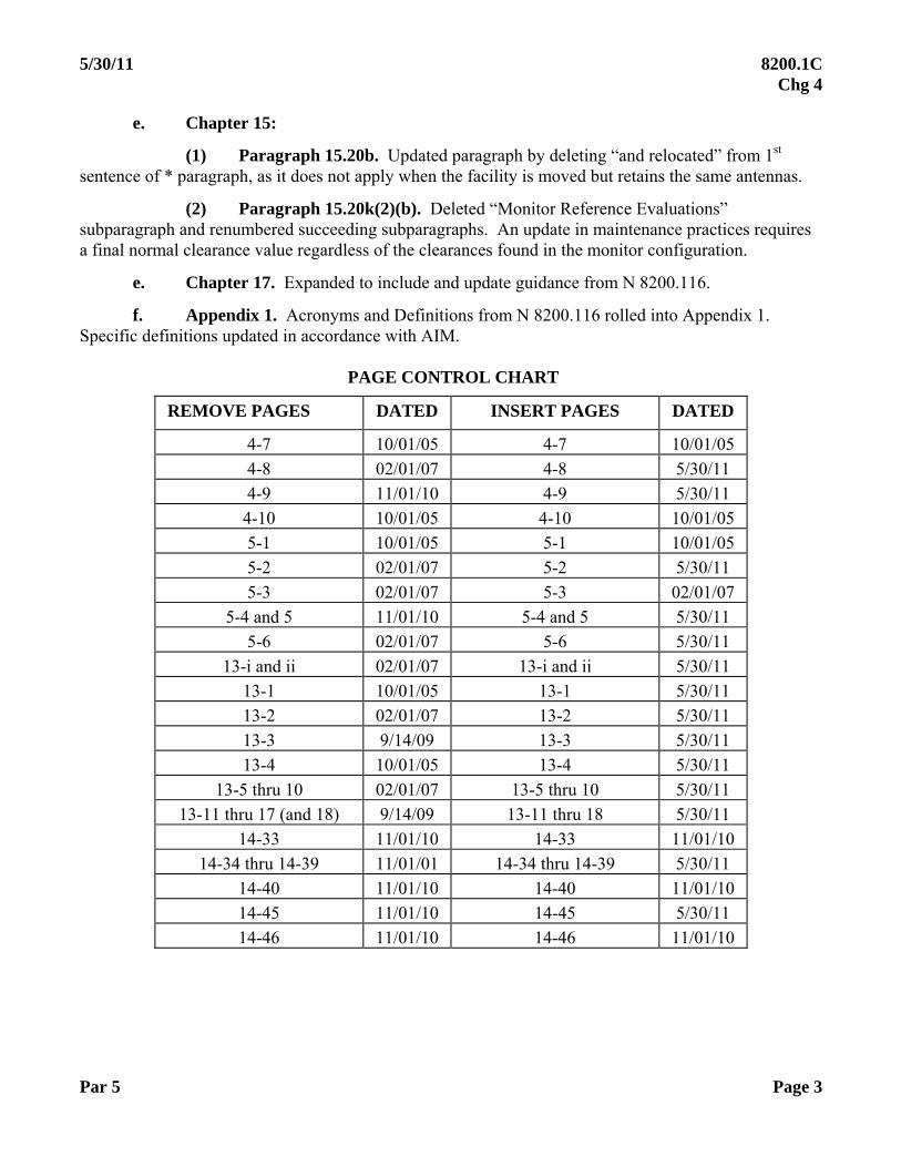
e. Chapter 15:
(1) Paragraph 15.20b. Updated paragraph by deleting “and relocated” from 1st sentence of * paragraph, as it does not apply when the facility is moved but retains the same antennas.
(2) Paragraph 15.20k(2)(b). Deleted “Monitor Reference Evaluations” subparagraph and renumbered succeeding subparagraphs. An update in maintenance practices requires a final normal clearance value regardless of the clearances found in the monitor configuration.
e. Chapter 17. Expanded to include and update guidance from N 8200.116.
f. Appendix 1. Acronyms and Definitions from N 8200.116 rolled into Appendix 1. Specific definitions updated in accordance with AIM.
PAGE CONTROL CHART
REMOVE PAGES DATED INSERT PAGES DATED
4-7 10/01/05 4-7 10/01/05
4-8 02/01/07 4-8 5/30/11
4-9 11/01/10 4-9 5/30/11
4-10 10/01/05 4-10 10/01/05
5-1 10/01/05 5-1 10/01/05
5-2 02/01/07 5-2 5/30/11
5-3 02/01/07 5-3 02/01/07
5-4 and 5 11/01/10 5-4 and 5 5/30/11
5-6 02/01/07 5-6 5/30/11
13-i and ii 02/01/07 13-i and ii 5/30/11
13-1 10/01/05 13-1 5/30/11
13-2 02/01/07 13-2 5/30/11
13-3 9/14/09 13-3 5/30/11
13-4 10/01/05 13-4 5/30/11
13-5 thru 10 02/01/07 13-5 thru 10 5/30/11
13-11 thru 17 (and 18) 9/14/09 13-11 thru 18 5/30/11
14-33 11/01/10 14-33 11/01/10
14-34 thru 14-39 11/01/01 14-34 thru 14-39 5/30/11
14-40 11/01/10 14-40 11/01/10
14-45 11/01/10 14-45 5/30/11
14-46 11/01/10 14-46 11/01/10
8200.1C Chg4
REMOVE PAGES
IS-27
IS-2S
IS-43
IS-44 and 4S
IS-46
\7-i thru 17-1 (and 2)
AI-I thru AI-S
AI-6 and AI-7
AI-S and AI-9
AI-IO thru AI-12
AI-i3 thru AI-IS
AI-16 thru AI-IS
AI-19 thru AI-32
AI-33
AI-34 thru AI-36
AI-37 thru AI-40
Edward W. Lucke, Jr.
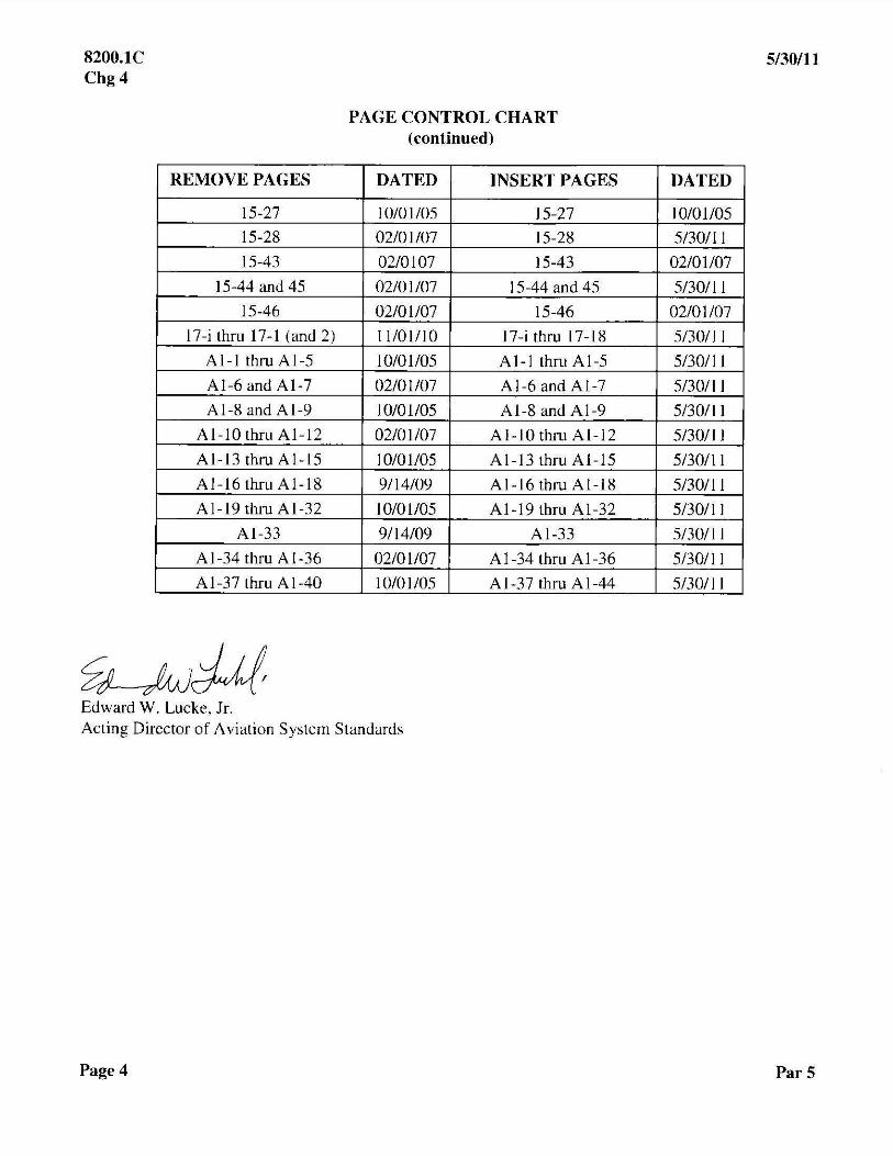
PAGE CONTROL CHART (continued)
DATED INSERT PAGES
10101/0S IS-27
02/01107 IS-2S
02/0107 IS-43
02/01/07 IS-44 and 4S
02/01/07 IS-46
1 I/O 1/10 17-i thru \7-IS
10101l0S AI-I thru AI-S
02/01/07 AI-6 and AI-7
IO/OIIOS AI-S and AI-9
02/01107 AI-IO thru AI-12
IO/OIIOS AI-i3 thru AI-IS
9/14/09 AI-16 thru AI-IS
I 010 1I0S AI-19 thru AI-32
9114/09 AI-33
02/01/07 AI-34 thru AI-36
10/0 I lOS AI-37 thru AI-44
Acting Director of Aviation System Standards
Page 4
5/30/11
DATED
10101l0S
S/30111
02/01/07
S/30111
02/01/07
S/3011 1
S/30111
S/30111
S/3011 1
S/3011 1
S/30111
S/30111
S/30/l 1
S/30111
S/30/11
SI3011 1
Par 5

Distribution: Special Addressees Initiated By: Aviation System Standards Flight Inspection Operations Flight Inspection Policy (AJW-331)
CHANGE U.S. DEPARTMENT OF TRANSPORTATION FEDERAL AVIATION ADMINISTRATION
Change 3 to 8200.1C
11/01/10
SUBJ: United States Standard Flight Inspection Manual 1. Purpose of This Change. This change transmits revisions to the United States Standard Flight Inspection Manual (USSFIM), FAA Order 8200.1C; Department of the Army Technical Manual TM 95-225; Department of the Navy Manual NAVAIR 16-1-520; and Department of the Air Force Manual AFMAN 11-225, dated October 1, 2005. 2. Audience. Air Traffic Technical Operations Eastern, Central, and Western Service Areas; Flight Inspection Operations Offices and crewmembers in Aviation System Standards; Flight Standards Flight Technologies and Procedures Division; NAS Implementation Centers; and special military addressees. 3. Where Can I Find This Change? Go to http://www.faa.gov/air_traffic/flight_info/avn/flightinspection/onlineinformation/8200/. Distribution within the Department of Defense is handled by the National Geospatial Intelligence Agency. For the U.S. Air Force, this revision is included in the AF STDPUBs CD-ROM and is available on the Internet (http://afpubs.hq.af.mil/). 4. Cancellations:
a. N 8200.115, FAA Order 8200.1C, Chapters 4 and 20, dated July 27, 2009
b. N 8200.117, Wide Area Multilateration (WAM), dated November 16, 2009
c. N 8200.120, Markers/ Beacons Major Axis Tolerance (Order 8200.1C, Chapter 24), dated August 20, 2010.
d. N 8200.121, MLS DME and TACAN Distance Accuracy Tolerances (Order 8200.1C, Chapter 24), dated August 20, 2010.

8200.1C 11/01/10 Chg 3
Page 2 Par 5
5. Explanation of Policy Changes:
a. Chapter 4:
(1) Paragraph 4.25, Table 4-1. Added WAM to list of facilities with 540-day periodic interval. VFR Aeronautical Charts deleted.
(2) Paragraph 4.25, Table 4-1, Note (5). Reworded note on periodic SIAP inspections to clarify requirements.
b. Chapter 5, Paragraph 5.12j(11). Reworded NOTAM wording per current guidance.
c. Chapter 7:
(1) Paragraph 7.12b(2)(b)1. Corrected instructions for starting position for a level run.
(2) Paragraph 7.12b(2)(c)1. Clarified description of Level Run method.
(3) Paragraph 7.12b(2)(c)2. Clarified description of On Path method.
(4) Paragraph 7.12b(2)(c)2a. Added reference to VASI diagrams.
(5) Paragraph 7.12b(3)(a). Added “normally”, as sometimes they are not aligned with the runway.
(6) Paragraph 7.12(4)(a). Added reference to blanking devices and baffles.
(7) Paragraph 7.12b(7)(a)2. Clarified how to determine VGSI coincidence with Baro_VNAV procedures.
(8) Paragraph 7.14c. Added information about blanking devices and baffles.
d. Chapter 14:
(1) Title chapter changed to “Surveillance”.
(2) Table of Contents and Paragraph 14.13. Changed Section 1 Title to include WAM and Paragraph 14.13 title to read, “Surveillance Radar/ ATCRBS Checklist”.
(3) Paragraph 14.10. Added WAM.
(4) Paragraph 14.11c. Removed specific instructions for reporting MSAW discrepancies that are below the level of detail appropriate for this order.
(5) Paragraph 14.11c(1)(a). Removed specific instructions for reporting MSAW discrepancies that are below the level or detail appropriate for this order.
(6) Paragraph 14.12a. Added reference for WAM inspections.

11/01/10 8200.1C Chg 3
Par 6 Page 3
(7) Paragraph 14.13. Changed title of Checklist to differentiate from WAM Checklist.
(8) Paragraph 14.14g(2). Facility Maintenance/ Engineering should choose a radial.
(9) Paragraph 14.14t(2). Removed specific instructions for reporting MSAW discrepancies that are below the level of detail appropriate for this order.
(10) Paragraph 14.15 in its entirety. Instructions for WAM inspections added.
(11) Paragraph 14.16 in its entirety. Instructions for WAM inspections added.
(12) Paragraph 14.17 in its entirety. Instructions for WAM inspections added.
(13) Paragraph 14.19, Tolerances. Updated with WAM tolerances per the WAM Notice.
(14) Paragraph 14.23b. Added exception to required equipment for Military Contingency or Natural Disaster.
(15) Paragraph 14.25b, Checklist. Note 4 changed to make Scan-Only an Mx request configuration change.
(16) Paragraph 14.25d. Opening paragraph updated with latest operational information from military, including the addition of TPN-31A PAR.
(17) Paragraph 14.25d, Checklist. “Rain/ Clear” column removed from “Measurements Required” section. This is a configuration, not an item to be checked.
(18) Paragraph 14.25d, Checklist. Note 2 clarified.
(19) Paragraph 14.25d, Checklist. Note 5 added. Added information on AZ-only mode of operation.
(20) Section 3, Automatic Dependent Surveillance Broadcast (ADSB), added as a reserved section to the Table of Contents and the end of Chapter 14.
e. Chapter 15:
(1) Paragraph 15.12h(7). Editorial only. “Angle” removed from “Structure” column of “Phase” in Endfire Glide Slope checklist.
f. Chapter 17. Changed title to Ground-Based Augmentation System (GBAS). The FAA version of GBAS is Local Area Augmentation System (LAAS).
g. Chapter 20. Added to Paragraph 20.10 as last sentence, “VFR charts will be evaluated on an on-demand, as needed basis and have no minimum periodic interval.”
h. Chapter 22. Deleted 3rd sentence. Localizer ESV(s) are not done outside Sector 1.
8200.1C 11/01/10 Chg 3
Page 4 Par 6
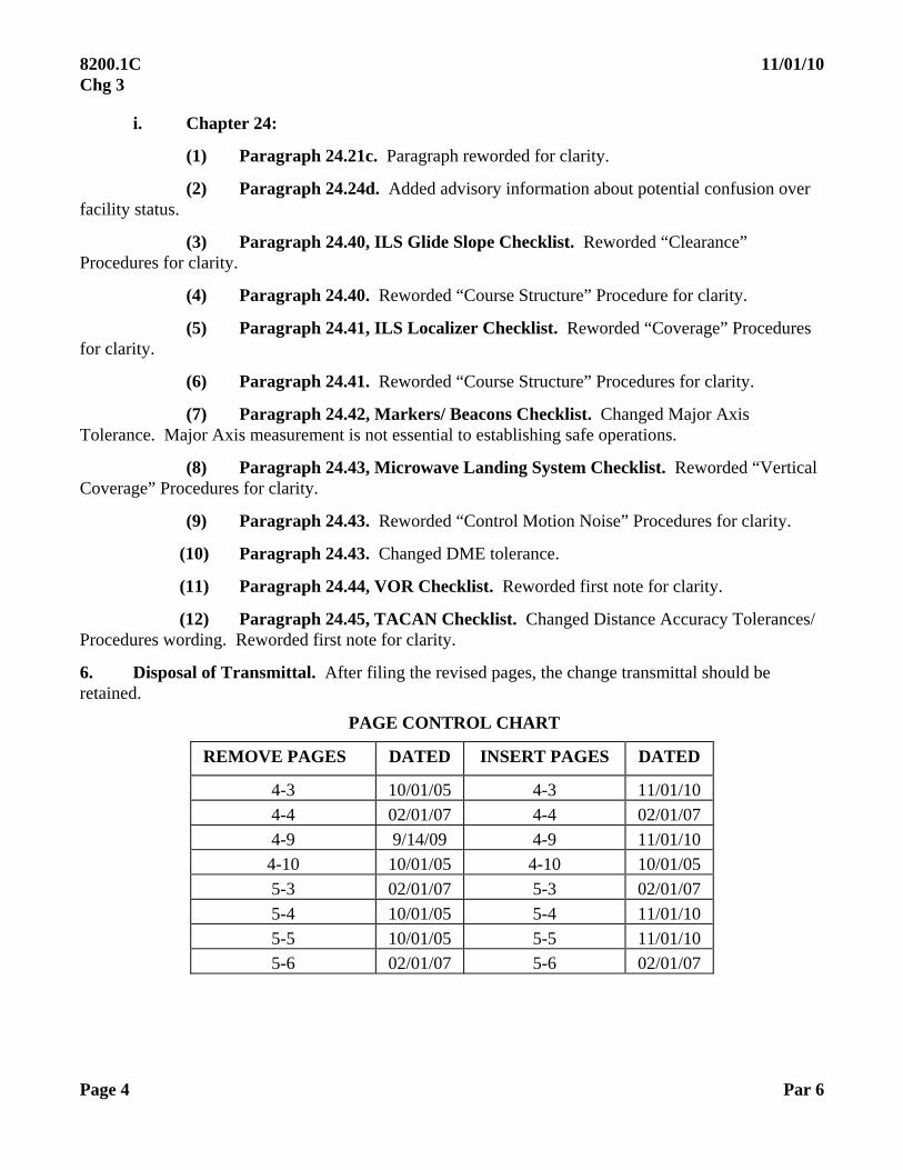
i. Chapter 24:
(1) Paragraph 24.21c. Paragraph reworded for clarity.
(2) Paragraph 24.24d. Added advisory information about potential confusion over facility status.
(3) Paragraph 24.40, ILS Glide Slope Checklist. Reworded “Clearance” Procedures for clarity.
(4) Paragraph 24.40. Reworded “Course Structure” Procedure for clarity.
(5) Paragraph 24.41, ILS Localizer Checklist. Reworded “Coverage” Procedures for clarity.
(6) Paragraph 24.41. Reworded “Course Structure” Procedures for clarity.
(7) Paragraph 24.42, Markers/ Beacons Checklist. Changed Major Axis Tolerance. Major Axis measurement is not essential to establishing safe operations.
(8) Paragraph 24.43, Microwave Landing System Checklist. Reworded “Vertical Coverage” Procedures for clarity.
(9) Paragraph 24.43. Reworded “Control Motion Noise” Procedures for clarity.
(10) Paragraph 24.43. Changed DME tolerance.
(11) Paragraph 24.44, VOR Checklist. Reworded first note for clarity.
(12) Paragraph 24.45, TACAN Checklist. Changed Distance Accuracy Tolerances/ Procedures wording. Reworded first note for clarity.
6. Disposal of Transmittal. After filing the revised pages, the change transmittal should be retained.
PAGE CONTROL CHART
REMOVE PAGES DATED INSERT PAGES DATED
4-3 10/01/05 4-3 11/01/10
4-4 02/01/07 4-4 02/01/07
4-9 9/14/09 4-9 11/01/10
4-10 10/01/05 4-10 10/01/05
5-3 02/01/07 5-3 02/01/07
5-4 10/01/05 5-4 11/01/10
5-5 10/01/05 5-5 11/01/10
5-6 02/01/07 5-6 02/01/07
11/01/10 8200.1C Chg 3
Par 6 Page 5
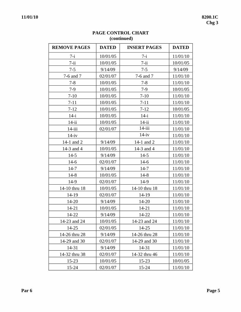
PAGE CONTROL CHART (continued)
REMOVE PAGES DATED INSERT PAGES DATED
7-i 10/01/05 7-i 11/01/10
7-ii 10/01/05 7-ii 10/01/05
7-5 9/14/09 7-5 9/14/09
7-6 and 7 02/01/07 7-6 and 7 11/01/10
7-8 10/01/05 7-8 11/01/10
7-9 10/01/05 7-9 10/01/05
7-10 10/01/05 7-10 11/01/10
7-11 10/01/05 7-11 11/01/10
7-12 10/01/05 7-12 10/01/05
14-i 10/01/05 14-i 11/01/10
14-ii 10/01/05 14-ii 11/01/10
14-iii 02/01/07 14-iii 11/01/10
14-iv 14-iv 11/01/10
14-1 and 2 9/14/09 14-1 and 2 11/01/10
14-3 and 4 10/01/05 14-3 and 4 11/01/10
14-5 9/14/09 14-5 11/01/10
14-6 02/01/07 14-6 11/01/10
14-7 9/14/09 14-7 11/01/10
14-8 10/01/05 14-8 11/01/10
14-9 02/01/07 14-9 11/01/10
14-10 thru 18 10/01/05 14-10 thru 18 11/01/10
14-19 02/01/07 14-19 11/01/10
14-20 9/14/09 14-20 11/01/10
14-21 10/01/05 14-21 11/01/10
14-22 9/14/09 14-22 11/01/10
14-23 and 24 10/01/05 14-23 and 24 11/01/10
14-25 02/01/05 14-25 11/01/10
14-26 thru 28 9/14/09 14-26 thru 28 11/01/10
14-29 and 30 02/01/07 14-29 and 30 11/01/10
14-31 9/14/09 14-31 11/01/10
14-32 thru 38 02/01/07 14-32 thru 46 11/01/10
15-23 10/01/05 15-23 10/01/05
15-24 02/01/07 15-24 11/01/10
8200.1C Chg3
Page 6
REMOVE PAGES
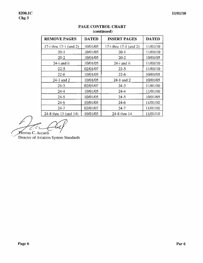
PAGE CONTROL CHART (continued)
DATED INSERT PAGES
17-i thru 17-1 (and 2) 10/01105 17-i thru 17-1 (and 2)
20-1 10/01105 20-1
20-2 10/01105 20-2
24-i and ii 10/01105 24-i and ii
22-5 02/01107 22-5
22-6 10/01105 22-6
24-1 and 2 10/01105 24-1 and 2
24-3 02/01107 24-3
24-4 10/01105 24-4
24-5 10/01105 24-5
24-6 10/01105 24-6
24-7 02/01107 24-7
24-8 thru 13 (and 14) 10/01105 24-81hru 14
11101110
DATED
11/01110
11101110
10/01105
11101110
11101110
10/01105
10/01105
11101110
11101110
10/01105
11101110
11101110
11101110
Par 6

Distribution: Special Addressees Initiated By: Air Traffic Operations (ATO-W) Aviation System Standards Flight Inspection Operations Flight Inspection Policy (AJW-331)
CHANGE U.S. DEPARTMENT OF TRANSPORTATION FEDERAL AVIATION ADMINISTRATION
Change 2 to 8200.1C
9/14/09
SUBJ: United States Standard Flight Inspection Manual 1. Purpose of This Change. This change transmits revisions to the United States Standard Flight Inspection Manual (USSFIM), FAA Order 8200.1C Department of the Army Technical Manual TM 95-225, Department of the Navy Manual NAVAIR 16-1-520, and Department of the Air Force Manual AFMAN 11-225, dated October 1, 2005. 2. Audience. Air Traffic Technical Operations Eastern, Central, and Western Service Areas; Flight Inspection Operations Offices and crewmembers in Aviation System Standards; Flight Standards Flight Technologies and Procedures Division; NAS Implementation Centers; and special military addressees. 3. Where Can I Find This Change? Go to http://www.avn.faa.gov). Distribution within the Department of Defense is handled by the National Geospatial Intelligence Agency. For the U.S. Air Force, this revision is included in the AF STDPUBs CD-ROM and is available on the Internet (http://afpubs.hq.af.mil/). 4. Cancellations. The following Notices are canceled:
a. N 8200.102, Pen and Ink Changes to FAA Order 8200.1C, Change 1, Chapters 4 and 7, dated July 10, 2007.
b. N 8200.103, FAA Order 8200.1C, United States Standard Flight Inspection Manual, Chapter 11, dated July 30, 2007.
c. N 8200.106, Changes to Precision Approach Radar Flight Inspection Requirements, FAA Order 8200.1C, Chapter 14, dated October 15, 2007.
d. N 8200.107, FAA Order 8200.1C, United States Standard Flight Inspection Manual, Chapter 15, dated November 5, 2007.
e. N 8200.108, Pen and Ink Changes to Chapters 4 and 13 of FAA Order 8200.1C, United States Standard Flight Inspection Manual, dated July 25, 2008.
f. N 8200.109, Pen and Ink Changes to Chapter 15 of FAA Order 8200.1C, United States Standard Flight Inspection Manual, Level Run Altitude Adjustment for Weather, dated July 25, 2008.

8200.1C 9/14/09 Chg 2
Page 2 Par 4
g. N 8200.112, FAA Order 8200.1C, Chapter 13 (Area Navigation), dated March 27, 2009.
h. N 8200.113, Elimination of Periodic Inspection of Approach Path Monitors (FAA Order 8200.1C, Chapters 4 and 14), dated April 13, 2009.
i. N 8200.114, RNAV WAAS Glidepath Fly-Up Verification (FAA Order 8200.1C, Chapter 13), dated April 20, 2009. 5. Explanation of Policy Changes:
a. Chapter 4:
(1) Paragraph 4.25, Table 4-1. In the last row of the Facility column, added “VGSI” after “Communications”. Deleted APM row from table; APM inspections will be conducted as a “by request” Special Inspection.
(2) Paragraph 4.25, Table 4-1, NOTE 5. Clarified periodic requirements for RNAV SIAP(s).
b. Chapter 6, Paragraph 6.15b(3)(b). Added detail and clarification to guidance for night evaluation of runway lighting systems.
c. Chapter 7:
(1) Paragraph 7.12a, NOTE. In the second sentence, changed “should” to “will”.
(2) Paragraph 7.22. Added detail and clarification for night evaluation requirements when a change has been made to lighting systems.
d. Chapter 11:
(1) Paragraph 11.20e. Changed “and changes to the applicable SIAP” to “and applicable changes to the final approach segment”.
(2) Paragraph 11.51, Checklist. Deleted “X” under “Periodic Inspection” for “VOT Reference Point”.
(3) Paragraph 11.60, VOT Tolerances. Under the Periodic Inspection (P) column for the Alignment Parameter, deleted the X that indicates 0.0° and inserted an X to indicate 1.0° or less.
e. Chapter 13:
(1) Paragraph 13.12a, Checklist, NOTE 3. Deleted the words “public RNAV” and inserted “RNAV-based”.
(2) Paragraph 13.33a and b. Deleted “(“Type A”)” and “(“Type B”)” references, as they are no longer charted. Deleted “may” in subparagraph b, as the 1 nm performance is required.
9/14/09 8200.1C Chg 2
Par 5 Page 3
(3) Paragraph 13.40. Clarified guidance for LP/ LPV WAAS RNAV procedures.
(4) Paragraph 13.42. Clarified guidance for LP/ LPV WAAS RNAV procedures.
(5) Paragraph 13.42c. Changed to read, “(b) Confirm WAAS glidepath full scale fly-up.” Clarified LP/ LPV guidance when encountering WAAS interference.
(6) Paragraph 13.44, Table 13-2. Footnote (1) added to identify Glide Path Alignment and Threshold Crossing Height as not applicable to LP; LP does not provide vertical guidance. Table 13-3. Added SNR-W parameter and tolerance.
f. Chapter 14:
(1) Paragraph 14.10c. In the last line, changed “general terrain map” to “general terrain monitor”.
(2) Paragraph 14.10c(1). Changed first two sentences to more accurately describe General Terrain Monitor (GTM) characteristics.
(3) Paragraph 14.11c, 2nd paragraph. Delete 2nd and 3rd sentences. The referenced website is no longer available.
(4) Paragraph 14.13, Checklist. Deleted “- GTM” from “MSAW – GTM” in last line and replaced Footnote (2). The change replaces the previous practice of scheduling periodic APM(s) with standard instrument approach procedures and leave the requirement to check GTM functionality during both commissioning and periodic ASR flight inspections.
(5) Paragraph 14.14t(2). Replaced “General Terrain Map (GTM)” with “General Terrain Monitor (GTM)”.
(6) Paragraph 14.23a, GENERIC PAR Checklist. Made the following changes to the checklist:
(a) Added “(3)” in the Inspection column next to “AC AZ”.
(b) Added “(3)” in the Inspection Column next to “AC EL”.
(c) Added an “X” in the “Approach #1” row under “AC AZ” and another under “AC EL”.
(d) Added an “X” in the “Approach #2” row under “AC AZ”.
(e) Added a third note under the checklist that reads, “(3) Apply commissioning tolerances when conducting a special inspection for antenna change (AZ or EL)”.
(7) Paragraph 14.23b, GPN-22, TPN-25 Checklist. Made the following changes to the checklist:
(a) In the Inspection column for “AC AZ”, changed it to read “AC” and add a “(9)” next to it.
(b) Added an “X” in the “Approach #3” row under the new “AC” heading.

8200.1C 9/14/09 Chg 2
Page 4 Par 5
(c) Added an “X” in the “Approach #4” row under the new “AC” heading.
(d) Added an “X” in the “Alternate Angle” row under the new “AC” heading.
(e) Deleted the entire “AC EL” column.
(f) Added a ninth note under checklist note (8) on Page 14-28, that reads,
“(9) Apply commissioning tolerances when conducting a special inspection for antenna change. These types of PAR(s) do not have separate AZ and EL antennas.”
(8) Paragraph 14.23d, MPN-25, TPN-31, FPN-67 (U.S. Army), GCA-2000 Checklist. Made the following changes to the checklist:
(a) Added “(4)” in the Inspection column next to “AC AZ”.
(b) Added “(4)” in the Inspection column next to “AC EL”.
(c) Added an “X” in the “Normal Approach” row under “AC AZ” and another under “AC EL”.
(d) Added an “X” in the “Lower Safe” row under “AC AZ”.
(e) Added a fourth note under the checklist that reads, “(4) Apply commissioning tolerances when conducting a special inspection for antenna change (AZ or EL).”
(9) Paragraph 14.16, Figure 14-5, Tolerances. Corrected errors in foot conversion to nautical miles in Footnotes (1) and (2).
g. Chapter 15. References to “FICO Technical Services Sub-Team (TSS)” changed to “Flight Inspection Policy”.
(1) Paragraph 15.10b. Office responsible for researching ILS facilities for higher category service updated.
(2) Paragraph 15.12a(7). Office responsible for researching ILS facility history for restriction removal updated.
(3) Paragraph 15.12b, Standby Equipment – Localizer/ Glide Slope. U.S. Army and U.S. Navy/ Marine Corps added to facility types.
(4) Paragraph 15.12h(5), Capture Effect Glide Slope. Corrected Measurements Required.
(5) Paragraph 15.20g(1), NOTE. U.S. Army and U.S. Navy/ Marine Corps added to facility types and reference to Order VN200 8240.52 changed to TI 8200.52.
(6) Paragraph 15.20g(2), Roll-Out Procedures. Deleted “at Part 139 airports”.
9/14/09 8200.1C Chg 2
Par 6 Page 5
(7) Paragraph 15.20g(2)(a), Site, Commissioning, Reconfiguration, and Categorization Inspections. Office responsible for researching ILS facility history for restriction removal update.
(8) Paragraph 15.20g(2)(b), Periodic or Special Inspections which require Structure Analysis. Office responsible for researching ILS facility history for restriction removal updated.
(9) Paragraph 15.30f(1), Approved Procedures – Level Run. Altitude limitation and adjustment guidance added.
(10) Paragraph 15.51f, NOTE. U.S. Army and U.S. Navy/ Marine Corps added to facility types.
(11) Paragraph 15.51f(1), Reference Values. U.S. Army and U.S. Navy/ Marine Corps added to facility types.
(12) Paragraphs 15.52a, 15.52b, and 15.52c, 75 MHz Marker Analysis. Corrected figure reference.
(13) Paragraph 15.52, Figure 15-9B. Corrected figure reference.
(14) Paragraph 15.60a, Localizers. U.S. Army and U.S. Navy/ Marine Corps added to facility types.
h. Appendix 1: On Page A1-16, added definition for Localizer Performance (LP) and clarified definition for Localizer Performance with Vertical Guidance (LPV). On Page A1-17, replaced definition of MSAW Approach Path Monitor (APM), replaced “MSAW General Terrain Map (GTM)” with “MSAW General Terrain Monitor (GTM)”, and replaced the definition of MSAW GTM. On Page A1-33, corrected acronym “GTM”.
i. Appendix 2:
(1) Paragraph A2.11b. Changed “should” to “must not be rounded off to an in-tolerance condition” when value exceeds a tolerance.
(2) Paragraph A2.15c. Moved parentheses to include Log in E1/ E2 computation, to match TI 8240.52.
8200.1C 9/14/09 Chg 2
Page 6 Par 6
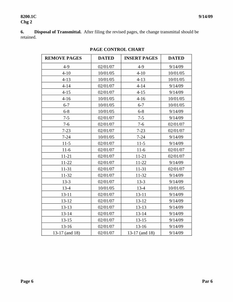
6. Disposal of Transmittal. After filing the revised pages, the change transmittal should be retained.
PAGE CONTROL CHART
REMOVE PAGES DATED INSERT PAGES DATED
4-9 02/01/07 4-9 9/14/09
4-10 10/01/05 4-10 10/01/05
4-13 10/01/05 4-13 10/01/05
4-14 02/01/07 4-14 9/14/09
4-15 02/01/07 4-15 9/14/09
4-16 10/01/05 4-16 10/01/05
6-7 10/01/05 6-7 10/01/05
6-8 10/01/05 6-8 9/14/09
7-5 02/01/07 7-5 9/14/09
7-6 02/01/07 7-6 02/01/07
7-23 02/01/07 7-23 02/01/07
7-24 10/01/05 7-24 9/14/09
11-5 02/01/07 11-5 9/14/09
11-6 02/01/07 11-6 02/01/07
11-21 02/01/07 11-21 02/01/07
11-22 02/01/07 11-22 9/14/09
11-31 02/01/07 11-31 02/01/07
11-32 02/01/07 11-32 9/14/09
13-3 02/01/07 13-3 9/14/09
13-4 10/01/05 13-4 10/01/05
13-11 02/01/07 13-11 9/14/09
13-12 02/01/07 13-12 9/14/09
13-13 02/01/07 13-13 9/14/09
13-14 02/01/07 13-14 9/14/09
13-15 02/01/07 13-15 9/14/09
13-16 02/01/07 13-16 9/14/09
13-17 (and 18) 02/01/07 13-17 (and 18) 9/14/09

9/14/09 8200.1C Chg 2
Par 6 Page 7
PAGE CONTROL CHART (continued)
REMOVE PAGES DATED INSERT PAGES DATED
14-1 02/01/07 14-1 9/14/09
14-2 10/01/05 14-2 9/14/09
14-5 02/01/07 14-5 9/14/09
14-6 02/01/07 14-6 02/01/07
14-7 10/01/05 14-7 9/14/09
14-8 10/01/05 14-8 10/01/05
14-19 02/01/07 14-19 02/01/07
14-20 02/01/07 14-20 9/14/09
14-21 10/01/05 14-21 10/01/05
14-22 10/01/05 14-22 9/14/09
14-25 02/01/07 14-25 02/01/07
14-26 02/01/07 14-26 9/14/09
14-27 10/01/05 14-27 9/14/09
14-28 02/01/07 14-28 9/14/09
14-31 02/01/07 14-31 9/14/09
14-32 02/01/07 14-32 02/01/07
15-1 02/01/07 15-1 9/14/09
15-2 10/01/05 15-2 10/01/05
15-9 02/01/07 15-9 9/14/09
15-10 02/01/07 15-10 02/01/07
15-19 10/0/1/05 15-19 10/01/05
15-20 02/01/07 15-20 9/14/09
15-31 02/01/07 15-31 02/01/07
15-32 02/01/07 15-32 9/14/09
15-33 02/01/07 15-33 9/14/09
15-34 02/01/07 15-34 9/14/09
15-35 02/01/07 15-35 9/14/09
15-36 02/01/07 15-36 9/14/09
15-55 02/01/07 15-55 9/14/09
15-56 02/01/07 15-56 02/01/07

8200.1C Chg2
REMOVE PAGES
15-69
15-70
15-73
15-74
15-77
15-78
AI-IS
AI-16
AI-17
AI-18
AI-33
AI-34
A2-1
A2-2
A2-5
A2-6
" ;;- /Y'7-· / /~&
Tbomas C. Accardi /
PAGE CONTROL CHART (continued)
DATED INSERT PAGES
02/01107 15-69
02/01107 15-70
02/01/07 15-73
02/01/07 15-74
02/0ll07 15-77
02/01107 15-78
10101/05 AI-IS
02/01107 AI-16
10/01/05 Al-17
10/01/05 AI-18
02/01/07 AI-33
02/01/07 AI-34
01/01/05 A2-1
10/01105 A2-2
10/01/05 A2-5
10/01/05 A2-6
Director of Aviation System Standards
Page 8
9/14/09
DATED
9/14/09
02/01107
9/14/09
02/01/07
02/0ll07
9/14/09
10/01/05
9/14/09
9/14/09
9/14/09
9/14/09
02/01/07
9/14/09
10/01105
9/14/09
10/01/05
Par 6

Distribution: Special Addressees Initiated By: Air Traffic Operations (ATO-W) Aviation System Standards Flight Inspection Operations Flight Inspection Policy (AJW-3310)
CHANGE U.S. DEPARTMENT OF TRANSPORTATION FEDERAL AVIATION ADMINISTRATION
CHG 1 to 8200.1C
02/01/07
SUBJ: United States Standard Flight Inspection Manual 1. PURPOSE. This change transmits revisions to the United States Standard Flight Inspection Manual (USSFIM), FAA Order 8200.1C Department of the Army Technical Manual TM 95-225, Department of the Navy Manual NAVAIR 16-1-520, and Department of the Air Force Manual AFMAN 11-225, dated October 1, 2005. 2. DISTRIBUTION. This change is distributed to selected offices on special mailing list ZVN-820. It is available on the Internet (http://www.avn.faa.gov). Distribution within the Department of Defense is handled by the National Geospatial Intelligence Agency. For the U.S. Air Force, this revision is included in the AF STDPUBs CD-ROM and is available on the Internet (http://afpubs.hq.af.mil/). 3. EFFECTIVE DATE. This order is effective March 1, 2007. 4. CANCELLATIONS. The following Notices are canceled:
a. N 8200.85, Interim Changes to FAA Order 8200.1C, dated December 1, 2005.
b. N 8200.87, Elimination of Periodic Inspections of Public RNAV SIAP(s) (FAA Order 8200.1C), dated March 20, 2006.
c. N 8200.90, Low and Medium Frequency Non-directional Beacons (NDB(s)), FAA Order 8200.1C, Chapter 12, dated May 15, 2006.
d. N 8200.91, Interim Change to FAA Order 8200.1C, Chapter 4, dated June 12, 2006.
e. N 8200.92, Interim Change to FAA Order 8200.1C, Chapter 11, Rho and Theta Systems, dated June 20, 2006.
f. N 8200.94, Interim Changes to Update FAA Order 8200.1C, dated July 25, 2006.
g. N 8200.95, Change to N 8200.94, Attachment (FAA Order 8200.1C, Chapter 15, dated August 22, 2006.
h. N 8200.96, Change to Precision Approach Radar Flight Inspection Requirements, FAA Order 8200.1C, Chapter, 14, dated September 1, 2006.
8200.1C 02/01/07 CHG 1
Page 2 Par 4
i. N 8200.99, Elimination of Periodic Flight Inspection of VGSI Systems (FAA Order 8200.1C), dated December 15, 2006.
j. N VN200 8200.21, Flight Inspection of RNAV Course-to-Fix (CF) and Holding, dated February 1, 2007.
k. N VN200 8200.22, Flight Inspection of RADAR Vector to Area Navigation (RNAV) Route, dated February 1, 2006.
l. N VN200 8200.27, ROC Check and SIAP Inspection Guidance, dated April 10, 2006.
m. N VN200 8200.31, PAR/ VGSI Recordings, dated June 28, 2006.
5. EXPLANATION OF CHANGES:
a. Chapter 4:
(1) Paragraphs 4.15b and 4.35d. Title of FAA Order 8240.36 changed to read, “Flight Inspection Report Processing System”.
(2) Paragraph 4.20a, first paragraph, last sentence. Changed to read, “The next inspection will be predicated upon the actual date of completion” to reflect guidance from Notice 8200.91.
(3) Paragraph 4.24a(2). “Airway Facilities” changed to “Air Traffic Technical Operations”.
(4) Paragraph 4.25. VGSI interval deleted from Table 4-2. No longer a requirement. Note (5) changed.
b. Chapter 5:
(1) Paragraph 5.12a, b, c, and g(2). Added “General” instructions. Deleted the “Flight Data Center (FDC) NOTAM(s)” paragraph. Reorganized the information in the “Facility NOTAM(s)” and “Instrument Flight Procedures” paragraphs. Directions were updated to match current offices and policies. More detail was added to the paragraph concerned with initiating NOTAM(s) for military facilities and/or instrument procedures.
(2) Paragraph 5.21. Removed requirement to retain source material for PAR, VGSI, and NDB inspections once the report has been archived. Added requirement to archive data logger files for all inspections utilizing AFIS, when conducted with a functioning data logger.
(3) Paragraph 5.22. Title of FAA Order 8240.36 changed to read, “Flight Inspection Report Processing System”.
02/01/07 8200.1C CHG 1
Par 5 Page 3
c. Chapter 6. Paragraph 6.13, Checklist. Note 2 added, “Public RNAV SIAP(s) have no periodic inspection requirement; however, a periodic obstacle verification must still be completed for the runway(s) serviced.” Note 2 added in the Periodic column for Final Approach Segment, Missed Approach Segment, and Obstacle Verification. (N 8200.87)
d. Chapter 7:
(1) Paragraph 7.12a:
(a) Last sentence. Document for facility data submission has changed from FAA Order 8240.36, Instructions for Flight Inspection Reporting, to FAA Order 8240.52, Aeronautical Data Management.
(b) Removed VGSI Periodic checklist requirements and supporting notes.
(2) Paragraph 7.12b(2)(c)1. Changed requirement to allow level run method to be used to determine the path angle of all VGSI types.
(3) Paragraphs 7.12b(2)(c)2. Requirement of On-Path Method for commissioning type inspection of PAPI removed. Level run method may be used. On-Path Method should be used to confirm questionable Level Run results. Minimum pair of light color change data for On-Path Method changed from four to three.
(4) Paragraph 7.12k. Added information for Omni-directional Runway End Identifier Lights (OD REIL).
(5) Paragraph 7.22d. Added flashing rate for OD REIL, 60 flashes per minute.
e. Chapter 11:
(1) Paragraph 11.12. Dedicated VOT checklist established in Paragraph 11.51.
(a) Footnote (13) added. ESV(s) must be revalidated any time a coverage orbit is required by this order.
(b) Footnote (14) added. VOT periodic requirements may be performed on the ground or in the air within the areas approved for use.
(2) Paragraph 11.20. Formatting change moves previous “Detailed Procedures” from Paragraph 11.21 to “Flight Inspection Specifications” in Paragraph 11.20.
(3) Paragraph 11.20e(2), 3rd sentence. Added frequency change as requirement to check VOR radials 5 either side of the approach radials and TACAN null checks.
(4) Paragraph 11.20f, 3rd sentence. Added frequency change as requirement for orbit evaluation.
(5) Paragraph 11.20h(1)(d) 1 and 2. Deleted 1 Airport Surface Markings and 2 Signs. Information included in Order VN 200 8240.52.

8200.1C 02/01/07 CHG 1
Page 4 Par 5
(6) Paragraph 11.33, COVERAGE. In the 2nd sentence, after “Stand-alone DME fixes,” added “located outside the FISSV.”
(7) Paragraph 11.41. Changed from “Detailed Procedures” to “Flight Inspection Specifications”.
(8) Paragraph 11.41l(9) Demand Mode. (Reserved) deleted. No planned use of this paragraph is expected.
(9) Paragraph 11.60c, DME Tolerances. Added Unlock information for Approach and En Route Radials to the Coverage parameter.
f. Chapter 12. Renumbered and reorganized major paragraphs. Deleted “Preflight Requirements”, “Analysis”, and “Adjustments” paragraphs. Added “Maintenance Actions Requiring Flight Inspection” and “Reporting” paragraphs. Divided into two Sections, “General” and “Flight Inspection Tolerances”.
(1) Paragraph 12.10. Added details to NDB classifications and added information about NDB identification signals.
(2) Paragraph 12.11. Renamed “Flight Inspection Specifications”. Contents include the inspection checklist and detailed specifications for each item. Made the following changes to the Checklist: Added columns for Antenna Change and Frequency Change. Deleted row labeled “Coverage” and inserted two new rows in its place labeled, “Coverage Orbit” and “Routes and Transitions”. Deleted the existing footnotes. Added new footnotes.
(3) Paragraph 12.12. Deleted “Flight Inspection Procedures” and renamed “Maintenance Actions Requiring Flight Inspection”. Added information about maintenance requiring flight inspections.
(4) Paragraph 12.13. Deleted “Analysis” and renamed “Flight Inspection Procedures”. Expanded directions for Identification and Voice. Deleted Coverage paragraph and replaced with Coverage Orbit; added 30 maximum when switching transmitters during coverage orbit. Changed SIAP paragraph to “Instrument Flight Procedures” with expanded directions. Added ESV paragraph. Added specific directions for standby power. Added new paragraph for Special Inspections, including directions for Antenna Change, Transmitter Change, and Frequency Change inspections.
(5) Paragraph 12.14. Moved “Tolerances” to Section 2, renamed “Reporting.”. Added instructions for reporting inspection results.
(6) Paragraph 12.15. Deleted “Adjustments.”
(7) Paragraph 12.20. Added Section 2, paragraph titled “Tolerances.” Added tolerance for holding patterns in Paragraphs 12.20d and 12.20e(2).
02/01/07 8200.1C CHG 1
Par 5 Page 5
g. Chapter 13:
(1) Paragraph 13.11d. Incorporated Notice VN200 8200.21.
(2) Paragraph 13.12a. Checklist. Added Note 3, regarding periodic inspection of Public RNAV LPV procedures”. “(3)” added to “P” in header of right column. (N 8200.87)
(3) Paragraph 13.13. Deleted reference to NFD. Changed “Resource and Data Management” to “Flight Inspection Policy”.
(4) Paragraph 13.21. Added FAA Order 8260.52.
(5) Paragraph 13.32a. Added Figure 1, SID Overview and Pilot Navigation Area Arc Radius information. Incorporated Notice VN200 8200.22.
(6) Paragraph 13.33. Substituted “RNAV 2” for “Type A” and “RNAV 1” for “Type B”, per AC 90-100 and charting to be effective February 2007. This change is due to the terms being changed in AC 90-100, which is aligning with ICAO terminology. AC 90-100A publication will be first quarter 2007.
(7) Paragraph 13.34. Added note 1 to DME Accuracy parameter (Notice VN200 8200.20).
(8) Paragraph 13.40. Changed HAT value supported from 250 ft to 200 ft (FAA Administrator announcement WAAS to 200 feet.
(9) Paragraph 13.42a, Checklist. Added Note 2, regarding periodic inspection of Public RNAV LPV procedures”. “(2)” added next to “P” in header of right column. (N 8200.87)
(10) Table 13-1. Added Note 2 regarding SNR from a WAAS GEO (Notice VN200 8200.23).
(11) Table 13-2. Changed WAAS Vertical Protection Level to include approach minima down to 200 feet.
h. Chapter 14:
(1) Paragraph 14.14q. Two sentences inserted following the first sentence. Allows UHF coverage to be confirmed by targets of opportunity. Minimizes impact after King Air fleet no longer has UHF capability.
(2) Paragraph 14.22. Changed from “Flight Inspection Procedures” to “Flight Inspection Specifications.”
8200.1C 02/01/07 CHG 1
Page 6 Par 5
(3) Paragraph 14.23a, Checklist for Generic PAR. Added requirement to checklist for Standby Transmitter to inspect both the A and B Cursors.
(4) Paragraph 14.23b, Checklist for GPN-22, TPN-25. Further explanation added to Note (5)(b).”
(5) Paragraph 14.23c, Checklist for TPN-22. Deleted all the text associated with “TPN-22 CONTROLLER INSTRUCTIONS.” Not relevant to flight inspection.
(6) Paragraph 14.23d, Checklist for MPN-25, TPN-31, FPN-67 (U.S. Army), GCA-2000. Added note to clarify Standby Transmitter inspection requirements.
(7) Paragraph 14.24. Changed from “Detailed Procedures” to “Flight Inspection Procedures.”
(8) Paragraph 14.24m. Two sentences inserted following the first sentence. Allows UHF coverage to be confirmed by targets of opportunity. Minimizes impact after King Air fleet no longer has UHF capability.
i. Chapter 15:
(1) Paragraph 15.10.b, NOTE deleted. No longer applicable, as single transmitter facilities are acceptable, provided they meet the Level 2 performance requirements. Updated new office name.
(2) Paragraph 15.12a(7). Updated new office name.
(3) Paragraph 15.12b. Added clarification to Standby Transmitter for Order 6750.49A, Change 5, Equality in Normal.
(4) Paragraphs 15.12h(1), (2), (3), (4), (5), and (7). Checklist changes made implementing Change 5 to FAA Order 6750.49A, per Notice 8200.88. Allows monitors to be checked on one transmitter only when facility is maintained using FAA Order 6750.49A.
(5) Para 15.12j(15). NOTAM Example for PAPI restriction corrected.
(6) Paragraph 15.20b. Replaced term LCA with specified altitude.
(7) Paragraph 15.20b. NOTE * Clarification of Installed added.
(8) Paragraph 15.20e. Replaced term LCA with procedural altitude.
(9) Paragraph 15.20f. Replaced term LCA with specified altitude.
(10) Paragraph 15.20g(1)(e). Added requirement to use Differential GPS AFIS “truth system” to determine alignment during commissioning-type inspections of LDA(s) where adequate visual checkpoints are not available. Clarified the use of Satisfactory (S) or Unsatisfactory (U) during a periodic when AFIS updates are impractical.
(11) Paragraph 15.20g(2). Corrected reference paragraph. Updated new office names.

02/01/07 8200.1C CHG 1
Par 5 Page 7
(12) Paragraph 15.20j. Replaced term LCA with specified altitudes.
(13) Paragraph 15.20k. Replaced term LCA with specified altitude. Corrected flow chart.
(14) Paragraph 15.20m. Replaced term LCA with specified altitude.
(15) Paragraph 15.30f. The level run altitude changed from GSI to an ICAO Standards and Recommended Practice (SARPS) of 1,500 feet. True altitude is added to compensate for temperature and altimeter with the intent that the height flown above the facility will remain the same from inspection to inspection. Requirement added to document the established level run altitude using Form VN200 8240-20. This will require the flight crew to submit a change to the AVNIS data sheet remark until all glide slopes have an established level run altitude documented. For reporting purposes on the ILS report (FAA Form 8240-8) and Form VN200 8240-20, report the established true altitude. For example, if the level run altitude is established at 2,500 ft true altitude and it was corrected to an indicated altitude of 2,449 ft, the established level run altitude documented on the data sheet and the reported level run altitude would both be 2,500 ft.
(16) Paragraph 15.30f(4). Replaced term GSI with established level run altitude.
(17) Paragraph 15.30i. Replaced GSI altitude with established level run altitude.
(18) Paragraph 15.30n. Replaced LCA with an altitude equal to 0.45 times the commissioned angle at 10 nm. Aligned policy with ICAO SARPS.
(19) Paragraph 15.51b. Added clarification of Rate of Change Reversal.
(20) Paragraph 15.51c(1)(c). Removed 10µA linearity tolerance per recommendations from third party engineering perspective.
(21) Paragraph 15.51c(2)(b). Replaced term LCA.
(22) Paragraph 15.51c(3)(a). Removed reference to “Point C”.
(23) Paragraph 15.51e. Corrected duplication of paragraphs by creating separate “CAT III Adjust and Maintain” paragraph. Renumbered remaining paragraphs under “ILS Maintenance Reference Tolerances and Alerts”, 15.51f and 15.51g.
(24) Paragraph 15.51f(1)(a)8, previously 15.51e(2)(a)8. Moved old paragraph to Order VN200 8240.52. Inserted text from previous Paragraph 15.51e(2)(a)9.
(25) Paragraph 15.51f(1)(a)9, previously 15.51e(2)(a)10. Implements Change 5 to FAA Order 6750.49A, per Notice 8200.88. Provides instructions for dual transmitter facilities when unable to meet equality limits.
(26) Paragraph 15.51f(2)(c), previously 15.51e(3)(c). Added emphasis for the flight inspector to issue a Maintenance Alert when a value exceeds the “adjust and maintain” limits.
8200.1C 02/01/07 CHG 1
Page 8 Par 5
(27) Previous Figure 15-8, Required Airborne Measurements per Facility Type, moved to Order VN200 8240.25.
(28) Paragraph 15.60a. Corrected alignment tolerance for independently monitored back courses from =8A to = 10A.
(29) Paragraph 15.60b. Corrected reference for Reference Datum Height (RDH).
(30) Previous Paragraphs 15.60c and d. Reference tolerance paragraphs moved to Order VN200 8240.52. Reference tolerances updated, per Notice 8200.88.
j. Chapter 16:
(1) Paragraph 16.20b(2)(b). Redefined positioning for checking vertical coverage.
(2) Paragraph 16.34e(4), Azimuth Collocated with Elevation Checklist: PFE Maximum Tolerance changed from “0.30” to“0.50.” Corrects previous typographical error.
(3) Paragraph 16.34e(5), Elevation Checklist: PFE Maximums Tolerance changed from “0.20” to “0.30.” Per Notice 8200.80, this is based on a typical Collocated MMLS installation located 1.0 nm from the published Missed Approach Point/ Decision Height, the tolerance change represents an increased allowable aircraft vertical position error, from 21 ft. to 32 ft.
k. Chapter 22:
(1) Paragraph 22.11b(2)(a). Deleted Note 1. The altitude to verify ESV is 0.45 times the commissioned angle at the ESV distance. 150µA or greater is required at an altitude equal to 0.45 times the commissioned angle at the ESV distance.
(2) Paragraph 22.11f. Updates descriptions of RNAV PRO, AFIS DME/ DME mode operation and reporting ESV results. Requires the inspection to be terminated if a DME designated as critical is off the air, or when there are 3 or less DME(s) to be evaluated and 1 of the 3 is out of service.
l. Chapter 24:
(1) Paragraph 24.21. Paragraph c added, “RNAV SIAP(s). RNAV and satellite-based SIAP(s) have no periodic inspection requirement, except obstacle verification. The periodic requirement to conduct obstacle verification may be evaluated independent of a SIAP inspection.” (N 8200.87)
(2) Paragraph 24.40. Changes ILS inspection requirements to include SBP, width and symmetry, and provides an exception for glide slope clearance checks during subsequent inspections of the same facility.
02/01/07 8200.1C CHG 1
Par 5 Page 9
m. Appendix 1:
(1) Updated definition of Critical DME per latest AC 90-100.
(2) Deleted LCA definition which no longer exists per LCA discussions about using ICAO definition.
(3) Added definitions for ILS-Glidepath Rate of Change, ILS-Glidepath Reversal, ILS-Half ILS Glidepath Sector, HLOM, and MLOM.
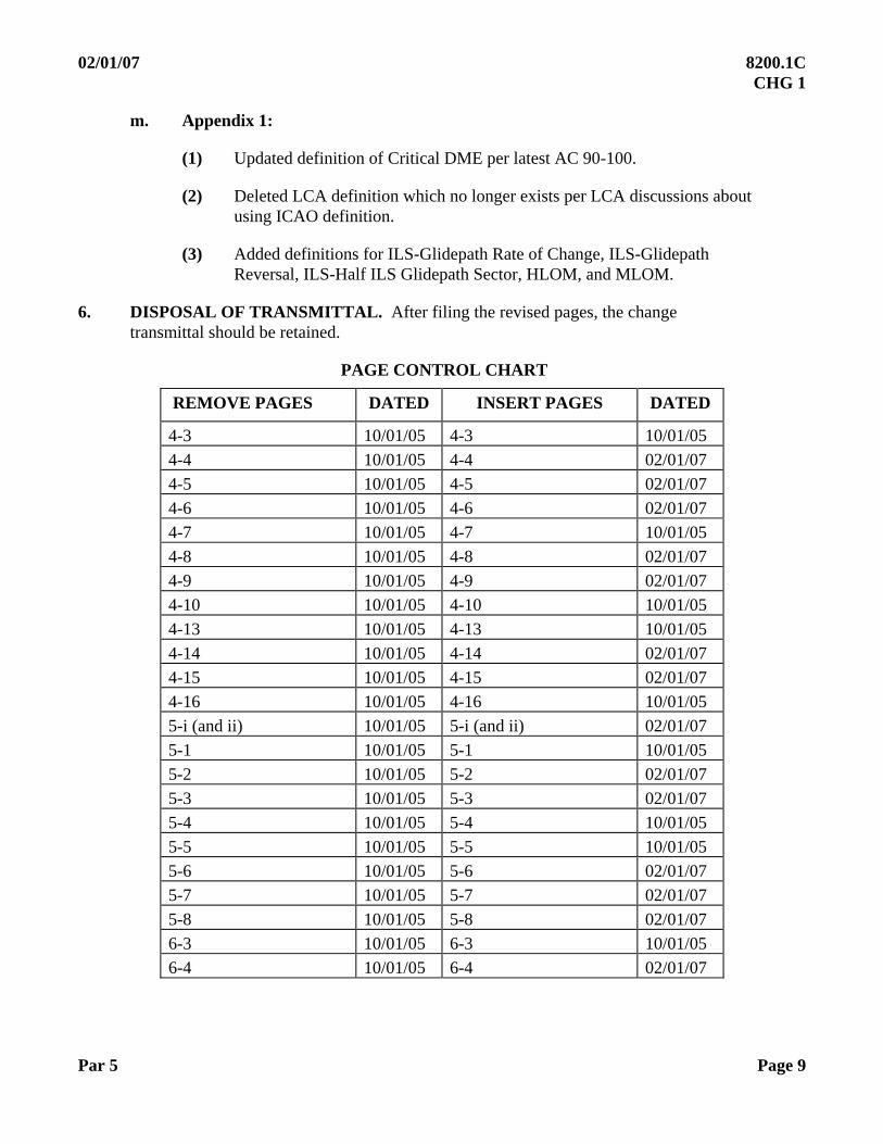
6. DISPOSAL OF TRANSMITTAL. After filing the revised pages, the change transmittal should be retained.
PAGE CONTROL CHART
REMOVE PAGES DATED INSERT PAGES DATED
4-3 10/01/05 4-3 10/01/05
4-4 10/01/05 4-4 02/01/07
4-5 10/01/05 4-5 02/01/07
4-6 10/01/05 4-6 02/01/07
4-7 10/01/05 4-7 10/01/05
4-8 10/01/05 4-8 02/01/07
4-9 10/01/05 4-9 02/01/07
4-10 10/01/05 4-10 10/01/05
4-13 10/01/05 4-13 10/01/05
4-14 10/01/05 4-14 02/01/07
4-15 10/01/05 4-15 02/01/07
4-16 10/01/05 4-16 10/01/05
5-i (and ii) 10/01/05 5-i (and ii) 02/01/07
5-1 10/01/05 5-1 10/01/05
5-2 10/01/05 5-2 02/01/07
5-3 10/01/05 5-3 02/01/07
5-4 10/01/05 5-4 10/01/05
5-5 10/01/05 5-5 10/01/05
5-6 10/01/05 5-6 02/01/07
5-7 10/01/05 5-7 02/01/07
5-8 10/01/05 5-8 02/01/07
6-3 10/01/05 6-3 10/01/05
6-4 10/01/05 6-4 02/01/07
8200.1C 02/01/07 CHG 1
Page 10 Par 6
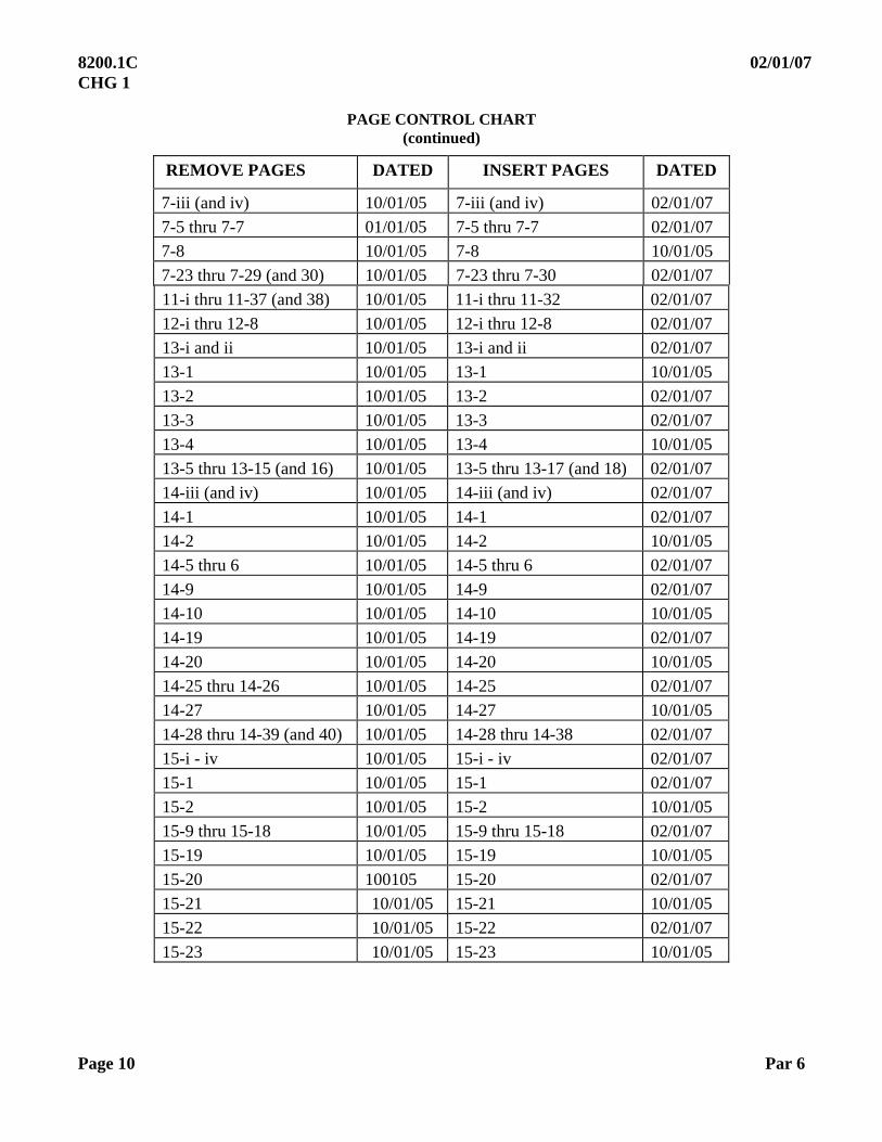
PAGE CONTROL CHART (continued)
REMOVE PAGES DATED INSERT PAGES DATED
7-iii (and iv) 10/01/05 7-iii (and iv) 02/01/07
7-5 thru 7-7 01/01/05 7-5 thru 7-7 02/01/07
7-8 10/01/05 7-8 10/01/05
7-23 thru 7-29 (and 30) 10/01/05 7-23 thru 7-30 02/01/07
11-i thru 11-37 (and 38) 10/01/05 11-i thru 11-32 02/01/07
12-i thru 12-8 10/01/05 12-i thru 12-8 02/01/07
13-i and ii 10/01/05 13-i and ii 02/01/07
13-1 10/01/05 13-1 10/01/05
13-2 10/01/05 13-2 02/01/07
13-3 10/01/05 13-3 02/01/07
13-4 10/01/05 13-4 10/01/05
13-5 thru 13-15 (and 16) 10/01/05 13-5 thru 13-17 (and 18) 02/01/07
14-iii (and iv) 10/01/05 14-iii (and iv) 02/01/07
14-1 10/01/05 14-1 02/01/07
14-2 10/01/05 14-2 10/01/05
14-5 thru 6 10/01/05 14-5 thru 6 02/01/07
14-9 10/01/05 14-9 02/01/07
14-10 10/01/05 14-10 10/01/05
14-19 10/01/05 14-19 02/01/07
14-20 10/01/05 14-20 10/01/05
14-25 thru 14-26 10/01/05 14-25 02/01/07
14-27 10/01/05 14-27 10/01/05
14-28 thru 14-39 (and 40) 10/01/05 14-28 thru 14-38 02/01/07
15-i - iv 10/01/05 15-i - iv 02/01/07
15-1 10/01/05 15-1 02/01/07
15-2 10/01/05 15-2 10/01/05
15-9 thru 15-18 10/01/05 15-9 thru 15-18 02/01/07
15-19 10/01/05 15-19 10/01/05
15-20 100105 15-20 02/01/07
15-21 10/01/05 15-21 10/01/05
15-22 10/01/05 15-22 02/01/07
15-23 10/01/05 15-23 10/01/05
02/01/07 8200.1C CHG 1
Par 6 Page 11
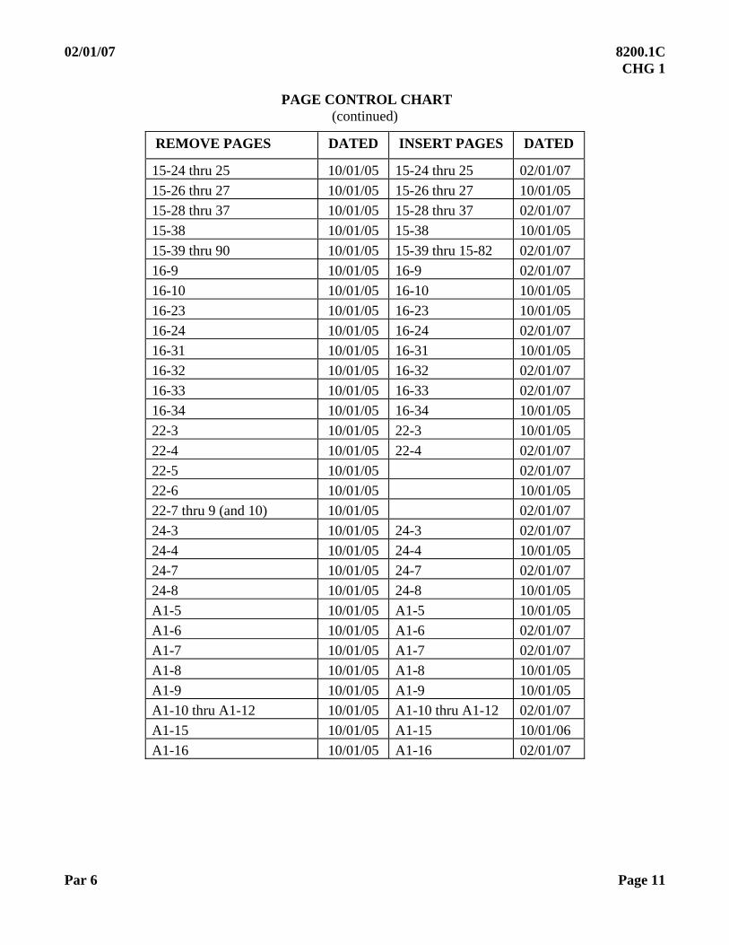
PAGE CONTROL CHART (continued)
REMOVE PAGES DATED INSERT PAGES DATED
15-24 thru 25 10/01/05 15-24 thru 25 02/01/07
15-26 thru 27 10/01/05 15-26 thru 27 10/01/05
15-28 thru 37 10/01/05 15-28 thru 37 02/01/07
15-38 10/01/05 15-38 10/01/05
15-39 thru 90 10/01/05 15-39 thru 15-82 02/01/07
16-9 10/01/05 16-9 02/01/07
16-10 10/01/05 16-10 10/01/05
16-23 10/01/05 16-23 10/01/05
16-24 10/01/05 16-24 02/01/07
16-31 10/01/05 16-31 10/01/05
16-32 10/01/05 16-32 02/01/07
16-33 10/01/05 16-33 02/01/07
16-34 10/01/05 16-34 10/01/05
22-3 10/01/05 22-3 10/01/05
22-4 10/01/05 22-4 02/01/07
22-5 10/01/05 02/01/07
22-6 10/01/05 10/01/05
22-7 thru 9 (and 10) 10/01/05 02/01/07
24-3 10/01/05 24-3 02/01/07
24-4 10/01/05 24-4 10/01/05
24-7 10/01/05 24-7 02/01/07
24-8 10/01/05 24-8 10/01/05
A1-5 10/01/05 A1-5 10/01/05
A1-6 10/01/05 A1-6 02/01/07
A1-7 10/01/05 A1-7 02/01/07
A1-8 10/01/05 A1-8 10/01/05
A1-9 10/01/05 A1-9 10/01/05
A1-10 thru A1-12 10/01/05 A1-10 thru A1-12 02/01/07
A1-15 10/01/05 A1-15 10/01/06
A1-16 10/01/05 A1-16 02/01/07
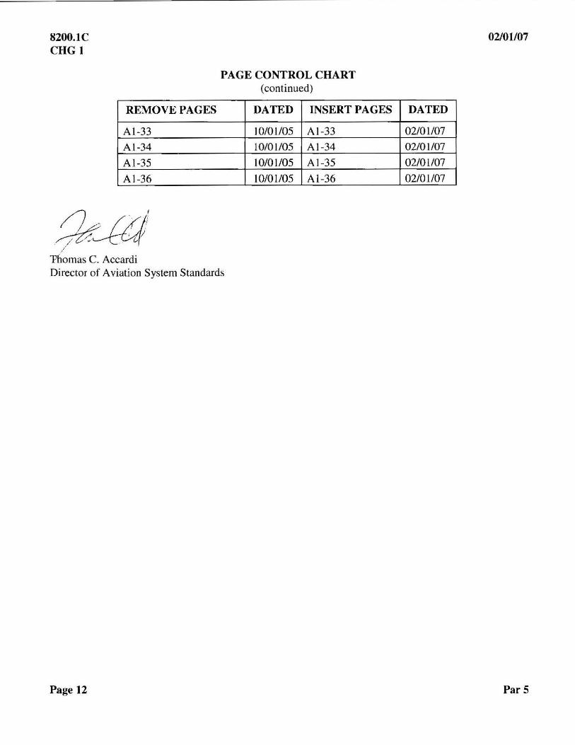
8200.1C CHG I
REMOVE PAGES
AI-33
AI-34
AI-35
AI-36
Thomas C. Accardi
PAGE CONTROL CHART (continued)
DATED INSERT PAGES
10/0 1105 AI-33
10/01/05 AI-34
10/01/05 AI-35
10/01105 AI-36
Director of Aviation System Standards
Page 12
02/01107
DATED
02/01/07
02/01/07
02/01107
02/01107
ParS
Page i
10/01/05
SUBJ: United States Standard Flight Inspection Manual (USSFIM) The purpose of this order is to prescribe standardized procedures for flight inspection of air navigation services. It is not intended as authorization for an agency to assume flight inspection authority over any group of services which are not now under its jurisdiction. Similarly, it carries no designation of responsibility within any agency unless such has been so designated in its usual procedural manner, such as general orders, regulations, etc.
This order is directive upon all personnel charged with the responsibility for execution of the flight inspection mission, when such personnel or organization is so designated by its agency. Compliance with this order, however, is not a substitute for common sense and sound judgment. Nothing in this order will be construed to relieve flight inspection crews or supervisory personnel of the responsibility of exercising initiative in the execution of the mission, or from taking such emergency action as the situation warrants.
The Federal Aviation Administration will coordinate and provide approved changes to this order by means of a page revision method. Revised pages will be transmitted by a Federal Aviation Administration Change or Notice. Recommendations concerning changes or additions to the subject material are welcomed and should be forwarded to one of the following addresses:
U.S. Army: Headquarters, Department of the Army, Office of the Deputy Chief of Staff, G-3/5/7, (DAMO-OD-A) Commander, United States Army Aeronautical Services Agency, 9325 Gunston Road, Building 1466, Suite N319, Fort Belvoir, Virginia 22060-5582 US Navy: Office of the Chief of Naval Operations (N785F), 2000 Navy Pentagon, Washington DC 20350-2000 US Air Force: Commander, Air Force Flight Standards Agency, 1535 Command Drive Suite D308, Andrews AFB MD 20331-7002 FAA: Director of Aviation System Standards, PO Box 20582, Oklahoma City OK 73125
U.S. DEPARTMENT OF TRANSPORTATION FEDERAL AVIATION ADMINISTRATION
ORDER
8200.1C

8200.tC 10/01105
This order of Flight Inspection Procedures has been officially approved by
US Army: Headqual1ers, Depal1ment of the Almy, Deputy Chief of Staff, G-3/S/7
US Navy Chief of Naval Operations, US Navy
US Air Force Chief of Staff, US Air Force
FAA: Director of Aviation System Standards
~tl; /{ j:Z, (/ Thorn ~Acc di
Director of Avi ion System Standal'ds Federal Aviation Administration
Page ii
10/01/05 8200.1C
Page iii (and iv)
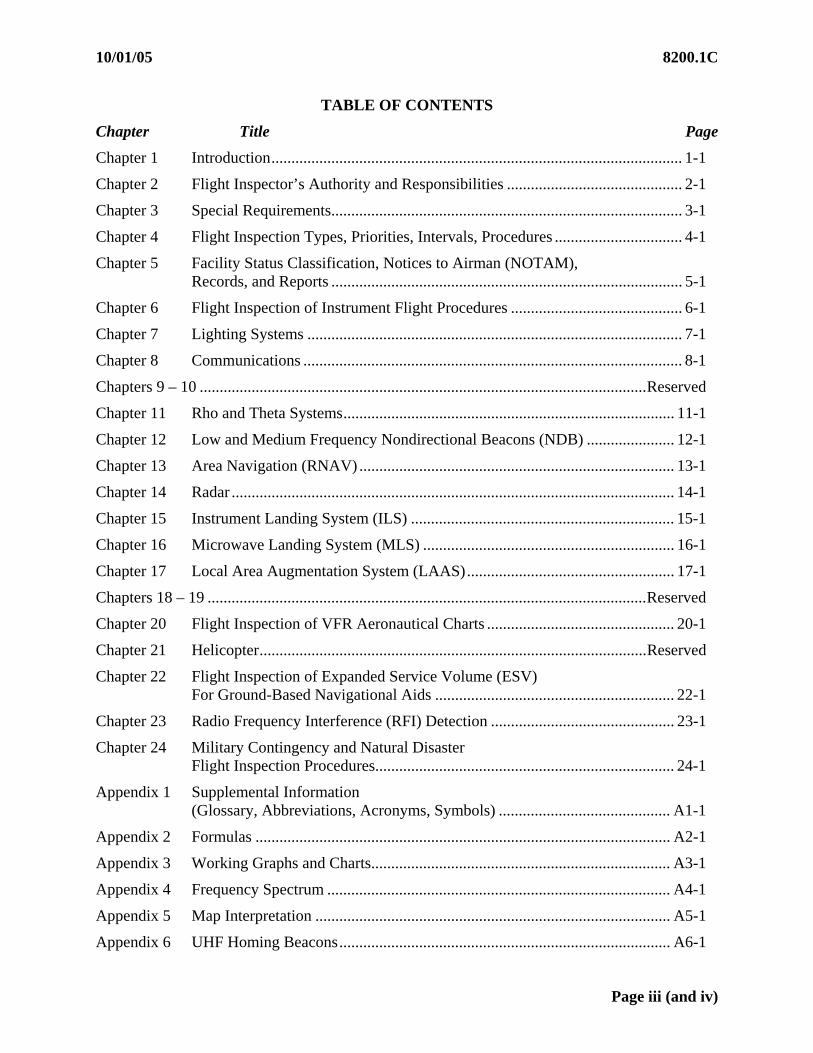
TABLE OF CONTENTS
Chapter Title Page
Chapter 1 Introduction....................................................................................................... 1-1
Chapter 2 Flight Inspector’s Authority and Responsibilities ............................................ 2-1
Chapter 3 Special Requirements........................................................................................ 3-1
Chapter 4 Flight Inspection Types, Priorities, Intervals, Procedures ................................ 4-1
Chapter 5 Facility Status Classification, Notices to Airman (NOTAM), Records, and Reports ........................................................................................ 5-1
Chapter 6 Flight Inspection of Instrument Flight Procedures ........................................... 6-1
Chapter 7 Lighting Systems .............................................................................................. 7-1
Chapter 8 Communications ............................................................................................... 8-1
Chapters 9 – 10 ................................................................................................................Reserved
Chapter 11 Rho and Theta Systems................................................................................... 11-1
Chapter 12 Low and Medium Frequency Nondirectional Beacons (NDB) ...................... 12-1
Chapter 13 Area Navigation (RNAV) ............................................................................... 13-1
Chapter 14 Radar ............................................................................................................... 14-1
Chapter 15 Instrument Landing System (ILS) .................................................................. 15-1
Chapter 16 Microwave Landing System (MLS) ............................................................... 16-1
Chapter 17 Local Area Augmentation System (LAAS).................................................... 17-1
Chapters 18 – 19 ..............................................................................................................Reserved
Chapter 20 Flight Inspection of VFR Aeronautical Charts ............................................... 20-1
Chapter 21 Helicopter.................................................................................................Reserved
Chapter 22 Flight Inspection of Expanded Service Volume (ESV) For Ground-Based Navigational Aids ............................................................ 22-1
Chapter 23 Radio Frequency Interference (RFI) Detection .............................................. 23-1
Chapter 24 Military Contingency and Natural Disaster Flight Inspection Procedures........................................................................... 24-1
Appendix 1 Supplemental Information (Glossary, Abbreviations, Acronyms, Symbols) ........................................... A1-1
Appendix 2 Formulas ........................................................................................................ A2-1
Appendix 3 Working Graphs and Charts........................................................................... A3-1
Appendix 4 Frequency Spectrum ...................................................................................... A4-1
Appendix 5 Map Interpretation ......................................................................................... A5-1
Appendix 6 UHF Homing Beacons................................................................................... A6-1


10/01/05 8200.1C
Page 1-i (and ii)
CHAPTER 1. INTRODUCTION
TABLE OF CONTENTS
Paragraphs Title Pages
1.10 PURPOSE......................................................................................................1-1 1.11 DISTRIBUTION ...........................................................................................1-1 1.12 EFFECTIVE DATE ......................................................................................1-1 1.13 CANCELLATIONS ......................................................................................1-1 1.14 EXPLANATION OF CHANGES.................................................................1-2 1.15 BACKGROUND...........................................................................................1-7 1.16 DEFINITIONS ..............................................................................................1-9 1.17 UNIT OF MEASUREMENT ........................................................................1-9 1.18 IDENTIFYING CHANGES IN THE TEXT OF THIS ORDER ..................1-9 1.19 AUTHORITY TO CHANGE THIS ORDER ...............................................1-9


10/01/05 8200.1C
Par 1.10 Page 1-1
CHAPTER 1. INTRODUCTION 1.10 PURPOSE. This order contains the policy, procedures, and criteria for flight inspection and certification of air navigation services, instrument flight procedures, and FAA VFR Aeronautical Charts. The order applies to the flight inspection of all National Airspace System (NAS) and Department of Defense air navigation services and instrument flight procedures. 1.11 DISTRIBUTION. This order is distributed to selected offices on special mailing list ZVN-820. It is available on the Internet (http://www.avn.faa.gov). Distribution within the Department of Defense is handled by the National Geospatial Intelligence Agency. For the U.S. Air Force, this revision is included in the AF STDPUBs CD-ROM and is available on the Internet (http://afpubs.hq.af.mil/). 1.12 EFFECTIVE DATE. This order is effective October 15, 2005. 1.13 CANCELLATIONS
a. The following orders are canceled:
(1) FAA Order 8200.1B, dated .January 2, 2003.
(2) FAA Order 8200.1B, Change 1, dated April 1, 2003.
(3) FAA Order 8200.1B, Change 2, dated June 21, 2004. b. The following notices are canceled.
(1) N 8200.72, Expanded Service Volume Process, dated October 15, 2004
(2) N 8200.74, Interim Changes to Flight Inspection Requirements, dated October 25, 2004
(3) N8200.75, Interim Change to FAA Order 8200.1B, Section 207, dated October 25, 2004
(4) N 8200.76, Authorization for Portable ILS/ VOR Reciever to Inspect VOTs, dated October 25, 2004
(5) N 8200.77, ILS Supporting Lower than Category I Minima, dated October 25, 2004
(6) N 8200.80, Interim Changes to Flight Inspection Tolerances, dated March 1, 2005
(7) N 8200.83, Visual Glide Slope Indicator (VGSI) Flight Inspection Requirements, dated August 30, 2005
(8) N 8200.84, Frequency of Periodic Flight Inspection, dated August 30, 2005.
(9) N VN200 8200.1, Runway Declared Distance Guidance, dated October 1, 2004

8200.1C 10/01/05
Page 1-2 Par 1.12
(10) N VN200 8200.4, Flight Inspection Frequencies, dated October 1, 2004
(11) N VN200 8200.6, WAAS Supported LNAV/ VNAV dated October 1, 2004
(12) N VN200 8200.7, Flight Inspection of GPS Overlay Procedures When the Primary Facility (e.g., VOR, NDB) is Out of Service (OTS) or Decommissioned, dated October 1, 2004
(13) N VN200 8200.8, ARR/ Orbit Dates, dated October 1, 2004
(14) N VN200 8200.14, Interim Guidance for FAA Order 8200.1, Section 214, dated February 7, 2005
(15) N VN200 8200.17, FAA Order 8200.1, Section 210, dated May 16, 2005.
(16) N VN200 8200.18, FAA Order 8200.1, Section 109, dated June 10, 2005.
1.14 EXPLANATION OF CHANGES. This order has been completely reformatted. It is in one-column format, versus two. The order is divided into chapters, with sections within chapters as necessary, IAW FAA Order 1320.1. Names of offices and organizations changed as a result of reorganization. Paragraph and item references in checklists and tolerance tables changed to reflect new numbering structure.
a. Former Appendix 1, Loran-C, was removed and archived electronically due to inactivity of system.
b. Chapter 2, Flight Inspection Crew Authority & Responsibilities (Formerly Sections 104, 105, and 106). Changed title from “Flight Inspector’s Authority and Responsibilities” to “Flight Inspection Crew Authority and Reponsbilities”.
c. Chapter 4, Section 3, General Flight Inspection Procedures (Formerly Section 106).
(1) Paragraph 4.32. Clarified an Airway Facilities requirement for two-way communications.
(2) Paragraph 4.32a(1). Added requirement to ensure Air Traffic is notified when a facility will be unusable during a flight inspection.
d. Chapter 5, Section 2, Records and Reports (Formerly Section 108). Added requirement to document Airborne Flight Inspection Calibrations.
e. Chapter 6, Flight Inspection of Instrument Flight Procedures (Formerly
Section 214). Interim guidance from N VN200 8200.14, Interim Guidance for FAA Order 8200.1, Section 214, added. Reference to obstacle verification for multiple approaches to a runway added. Skipping of a periodic obstacle verification inspection removed. Specific information for flyability removed, to be included in Order VN200 8240.52, Flight Inspection Standard Operating Procedures.
10/01/05 8200.1C
Par 1.13 Page 1-3
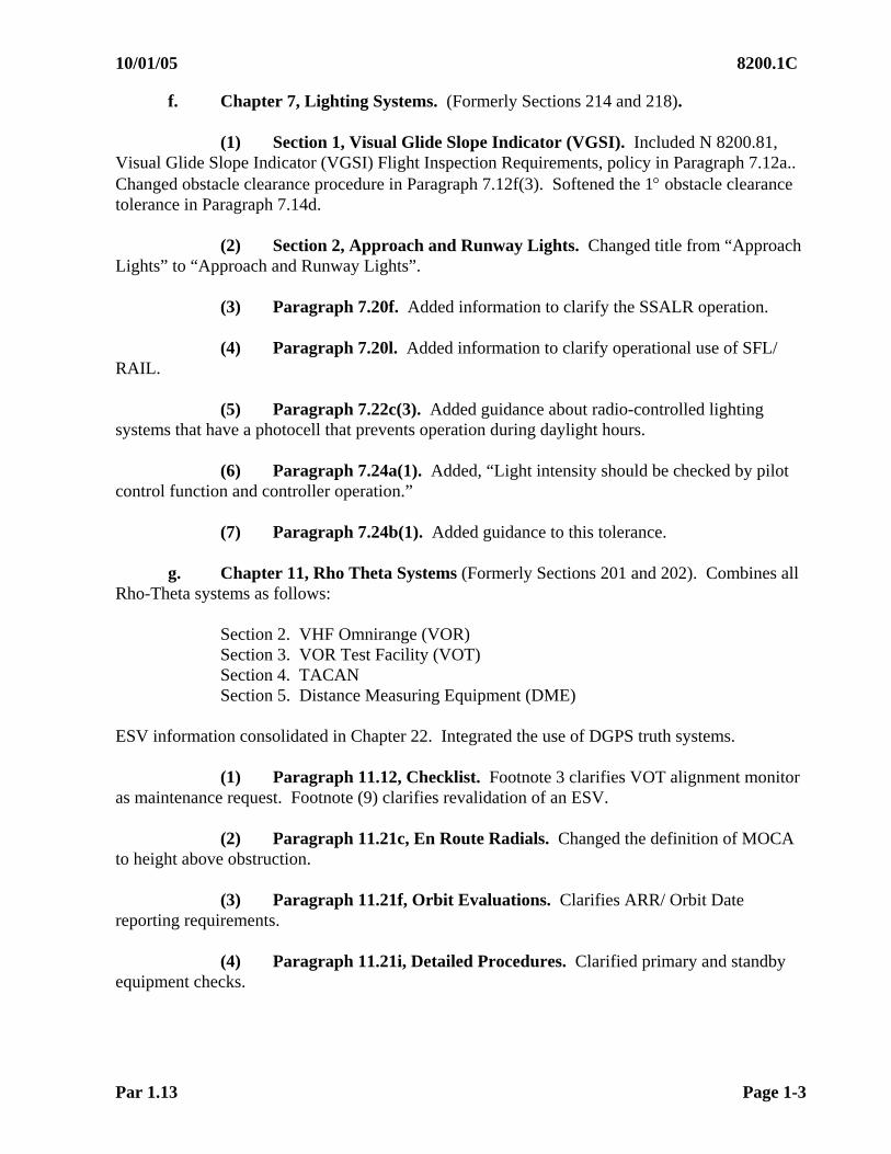
f. Chapter 7, Lighting Systems. (Formerly Sections 214 and 218).
(1) Section 1, Visual Glide Slope Indicator (VGSI). Included N 8200.81, Visual Glide Slope Indicator (VGSI) Flight Inspection Requirements, policy in Paragraph 7.12a.. Changed obstacle clearance procedure in Paragraph 7.12f(3). Softened the 1 obstacle clearance tolerance in Paragraph 7.14d.
(2) Section 2, Approach and Runway Lights. Changed title from “Approach Lights” to “Approach and Runway Lights”.
(3) Paragraph 7.20f. Added information to clarify the SSALR operation.
(4) Paragraph 7.20l. Added information to clarify operational use of SFL/ RAIL.
(5) Paragraph 7.22c(3). Added guidance about radio-controlled lighting systems that have a photocell that prevents operation during daylight hours.
(6) Paragraph 7.24a(1). Added, “Light intensity should be checked by pilot control function and controller operation.”
(7) Paragraph 7.24b(1). Added guidance to this tolerance.
g. Chapter 11, Rho Theta Systems (Formerly Sections 201 and 202). Combines all Rho-Theta systems as follows:
Section 2. VHF Omnirange (VOR) Section 3. VOR Test Facility (VOT) Section 4. TACAN Section 5. Distance Measuring Equipment (DME)
ESV information consolidated in Chapter 22. Integrated the use of DGPS truth systems.
(1) Paragraph 11.12, Checklist. Footnote 3 clarifies VOT alignment monitor as maintenance request. Footnote (9) clarifies revalidation of an ESV.
(2) Paragraph 11.21c, En Route Radials. Changed the definition of MOCA to height above obstruction.
(3) Paragraph 11.21f, Orbit Evaluations. Clarifies ARR/ Orbit Date reporting requirements.
(4) Paragraph 11.21i, Detailed Procedures. Clarified primary and standby equipment checks.

8200.1C 10/01/05
Page 1-4 Par 1.13
(5) Paragraph 11.22c, Sensing and Rotation. Clarifies sensing and rotation verification by observation of instrumentation.
(6) Paragraph 11.22e, Polarization. Clarifies polarization is to be checked on one transmitter only.
(7) Paragraph 11.53e(2). Incorporated the use of a PIR for a Periodic or Special VOT inspection and incorporated Notice 8200.76.
h. Chapter 13, RNAV (Formerly Sections 209 and 210). Area Navigation and
RNAV WAAS combined into this chapter. Readily available public information removed from introductions. Information duplicated in Chapter 6, Flight Inspection of Instrument Procedures, removed. Avionics specific information duplicated in aircraft manuals removed. RNP levels defined. DME/ DME RNAV analysis and tolerance changed to reflect AFIS software evaluation capability. AFIS software delivered December 2004. AFIS announced data for LPV Glide Path Alignment have been tightened. Representative of precision required for FAS data block. AFIS announced data for LPV Threshold Crossing Height added. AFIS software errors for calculating TCH have been improved. Introduction to LAAS added.
i. Chapter 14, Radar.
(1) Paragraph 14.14t, Minimum Safe Altitude Warning (MSAW). Wording changed to agree with Order VN200 8240.4, Daily Flight Log (DFL), FAA Form 4040-5. Reference to block number removed and replaced with “block title”.
(2) Paragraph 14.23b, GPN-22, TPN-25 Checklist. Added reference 14.24h to Approach 1. Add Periodic requirement to Approach 3.
j. Chapter 15, Instrument Landing System (ILS)(Formerly Sections 217 and 219). ILS and 75 MHz beacons combined into this chapter. Integrated the use of DGPS. Incorporated Rollout guidance. Titles of offices changed due to reorganization. Hazardously Misleading Information (HMI) guidance added.
(1) Paragraph 15.10. Expanded definition of “ILS used for Higher Category of Service”.
(2) Paragraph 15.12h, Checklists.
(a) Paragraph 15.12h(1), Single Frequency Localizer. Added Footnotes (9) and (10). Added “One XMTR Only” requirement to Clearance Comparability. “Caution: HMI” added to Modulation Equality, Phasing, and Alignment Monitors.
(b) Paragraph 15.12h(2), Dual Frequency Localizer. Added Footnotes (7) and (8). Added “One XMTR Only” requirement to Clearance Comparability. “Caution: HMI” added to Modulation Equality, Phasing, and Alignment Monitors. Changed Course Wide/ Clearance Normal Reference Alarm to MR on Dual Frequency Checklist.
10/01/05 8200.1C
Par 1.13 Page 1-5
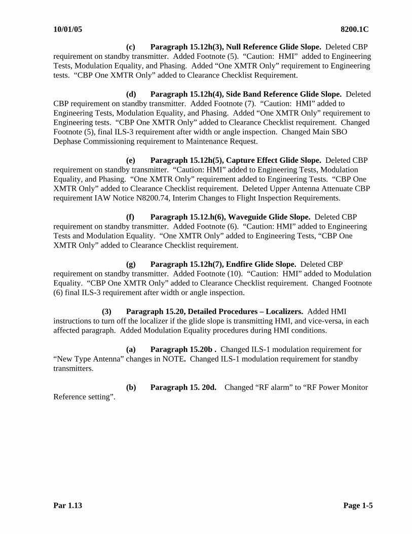
(c) Paragraph 15.12h(3), Null Reference Glide Slope. Deleted CBP requirement on standby transmitter. Added Footnote (5). “Caution: HMI” added to Engineering Tests, Modulation Equality, and Phasing. Added “One XMTR Only” requirement to Engineering tests. “CBP One XMTR Only” added to Clearance Checklist Requirement.
(d) Paragraph 15.12h(4), Side Band Reference Glide Slope. Deleted CBP requirement on standby transmitter. Added Footnote (7). “Caution: HMI” added to Engineering Tests, Modulation Equality, and Phasing. Added “One XMTR Only” requirement to Engineering tests. “CBP One XMTR Only” added to Clearance Checklist requirement. Changed Footnote (5), final ILS-3 requirement after width or angle inspection. Changed Main SBO Dephase Commissioning requirement to Maintenance Request.
(e) Paragraph 15.12h(5), Capture Effect Glide Slope. Deleted CBP requirement on standby transmitter. “Caution: HMI” added to Engineering Tests, Modulation Equality, and Phasing. “One XMTR Only” requirement added to Engineering Tests. “CBP One XMTR Only” added to Clearance Checklist requirement. Deleted Upper Antenna Attenuate CBP requirement IAW Notice N8200.74, Interim Changes to Flight Inspection Requirements.
(f) Paragraph 15.12.h(6), Waveguide Glide Slope. Deleted CBP requirement on standby transmitter. Added Footnote (6). “Caution: HMI” added to Engineering Tests and Modulation Equality. “One XMTR Only” added to Engineering Tests, “CBP One XMTR Only” added to Clearance Checklist requirement.
(g) Paragraph 15.12h(7), Endfire Glide Slope. Deleted CBP requirement on standby transmitter. Added Footnote (10). “Caution: HMI” added to Modulation Equality. “CBP One XMTR Only” added to Clearance Checklist requirement. Changed Footnote (6) final ILS-3 requirement after width or angle inspection.
(3) Paragraph 15.20, Detailed Procedures – Localizers. Added HMI instructions to turn off the localizer if the glide slope is transmitting HMI, and vice-versa, in each affected paragraph. Added Modulation Equality procedures during HMI conditions.
(a) Paragraph 15.20b . Changed ILS-1 modulation requirement for
“New Type Antenna” changes in NOTE. Changed ILS-1 modulation requirement for standby transmitters.
(b) Paragraph 15. 20d. Changed “RF alarm” to “RF Power Monitor Reference setting”.
8200.1C 10/01/05
Page 1-6 Par 1.13
(c) Paragraph 15.20f. Changed localizer course width distances to match clearance distances. Deleted the requirement for modulation to be in tolerance for course width measurements. Re-defined LCA to coincide with ICAO Annex 10 and Document 8071, International Civil Aviation Organization (ICAO) Manual on Testing of Radio, as pertains to localizer. Added a provision to check course width to a distance of 14 nm on periodic checks. Deleted the requirement to document the data sheet if a higher altitude than LCA is flown, based on width comparability. Deleted Clearance plotting requirements.
(d) Paragraph 15.20g. Moved requirement to establish a modulation balance reference for “Point-In-Space” LDA(s). References DGPS truth system in lieu of an “S/U” alignment for “Point-In-Space” LDA(s). Added localizer structure rollout guidance.
(e) Paragraph 15.20g(2). Added localizer rollout procedures IAW N8200.77, ILS Supporting Lower than Category I Minima.
(f) Paragraph 15.20i. Deleted localizer monitor requirements for lowering LCA. Added reference to localizer alignment monitor requirements only per region request. Deleted the localizer RF monitor reference for lowering LCA.
(g) Paragraph 15.20j. Clarified localizer RF monitor reference when terrain is a factor. Clarified the LCA requirement for localizer RF monitor reference check. Deleted reference to “Requested ESV(s)” pertaining to localizer RF monitor reference checks.
(h) Paragraph 15.20k. Redefined LCA to coincide with ICAO Annex 10 and Document 8071, as pertains to localizer.
(i) Paragraph 15.20m. Added instructions for Fixes, Transitions, SID(s), and STAR (s) when the procedure altitude is below LCA.
(j) Paragraph 15.20o. Deleted the reference to checking Ident and Voice at LCA.
(4) Paragraph 15.30, Glide Slope Flight Inspection Procedures.
(a) Paragraph 15.30d. Added reference to flying the procedural ground track during glide slope phasing. Loosened the requirement for a 1 CBP during glide sope PV. Changed glide slope SBO dephase 30 PV checks to maintenance request in Paragraph 15.30d(3)(a). Added reference to Clearance XMTR status during Glide Slope Phasing Procedures 1 and 2 in Paragraph 15.30d(3)(b)1 and 2.
(b) Paragraph 15.30f. Deleted reference to “GSI corrected to true altitude” on altitude requirement for G/S ILS-2 runs.
(c) Paragraph 15.30n. Restructured “RF Power Monitor Reference” paragraph.
10/01/05 8200.1C
Par 1.13 Page 1-7
(5) Paragraph 15.51, Analysis. Expanded on the Reversal/ Rate-of-Change criteria for standardization purposes. Expanded Order 6750.49, ILS Handbook, requirements into this order. Added Figures 15-8A – F, ILS Reference Requirements checklists.
(6) Paragraph 15.60, Tolerances. Added “Initial” tolerance alignment requirements.
k. Chapter 16, Microwave Landing System (MLS)(Formerly Section 220). Integrated the use of DGPS.
(1) Paragraph 16.20, MLS. Added “DA 200 ft or less” requirement to evaluate an approach below 100 ft DA in Paragraph 16.20b(3)(d). Added to select the MGP angle on AFIS, fly (MGP X 0.75) – 02.5 angle to show full-scale deflection (FSD) in Paragraph 16.20b(4)(c). Changed CBP from fixed angle to FSD. AZ reference point changed to ARD only if DA is less than 200 ft in Paragraph 16.20b(3)(c)3.
(2) Paragraph 16.31, Mobile MLS. Changed Footnote (2) and added Footnote (6)in Checklist. Clarified CEU Change Checklist. Deleted requirement to check AZ/ EL for DEU Change.
(3) Paragraph 16.32. Clarified MCE/ Coverage check in Paragraph
16.32c(2)(a) and (b). Clarified tolerance application for DH above/ below 200 ft. Notice 8200.80, Interim Changes to Flight Inspection Tolerances, added to Paragraph 16.34e(3).
l. Chapter 22, Expanded Service Volume.
(1) Paragraph 22.11b(1). Clarifies NDB crossing radial for 5.
(2) Paragraph 22.12. Incorporates N 8200.72, Expanded Service Volume Process.
m. Appendix 1 (Formerly Section 301). Definition for ILS – Lowest Coverage Altitude clarified on Page A1-12.
n. Appendix 2, (Formerly Section 302).
(1) Paragraph A2.15c. Added parentheses to dual frequency localizer power ratio formula for clarification.
(2) Paragraph A2.16. Added glide slope reference to FAA Order 8240.36 for
the purpose of obtaining formula to calculate “Point C”.

8200.1C 10/01/05
Page 1-8 Par 1.14
1.15 BACKGROUND
a. U.S. Policy. International Group on International Aviation (IGIA) 777/4.6G specifies that the FAA will provide flight inspection of the common air navigation system, U.S. military aids worldwide, reimbursable services to other countries, and encourage other countries to establish their own flight inspection capability. The VFR Flight Inspection Program (VFR FIP) is a support activity of the FAA/ Aviation System Standards (AVN)/ National Aeronautical Charting Office (NACO). In keeping with the statutory responsibilities of the Federal Aviation Act of 1958, NACO is responsible for maintaining the standards of accuracy, completeness, and currency of all air cartographic materials that will meet the minimum standards approved by the FAA and/or the Inter-Agency Air Cartographic Committee’s U.S. Government Chart Specifications. To supplement office review and ensure the accuracy, completeness, and overall adequacy of these charts, the FAA conducts a systematic program of chart verification by visual flight inspection.
b. Program Objectives. The following objectives reflect FAA philosophy. Current and future planning should be aligned to these objectives.
(1) Adequate site survey and analysis of ground and inflight data.
(2) Correlated ground and flight measurements at the time of facility commissionings.
(3) System reliability to meet justified user needs. (4) Maximum reliance on ground measurements supported by inflight
measurements of those facility parameters which cannot satisfactorily be measured by other means.
(5) Through continued inflight surveillance of the National Airspace System
(NAS), determine system adequacy, isolate discrepancies, and provide feedback for system improvement.
(6) To review, verify, and edit topographic, cultural, and obstruction data
(roads, railroads, antennas, towers, power lines, rivers, urban areas, etc.) depicted on FAA VFR Aeronautical Charts for accuracy and navigational usefulness.
c. The Interface with Agency Rules. Instrument flight procedures and ATC services require periodic flight surveillance of the air navigation system and dictate strict enforcement of the performance standards adopted for each aid.
d. Flight inspection programs were unified under the FAA by Executive Order 11047, August 28, 1962, subject to the provisions of Executive Order 11161, July 7, 1964. The programs are based on joint DOD/FAA standards, procedures, techniques, and criteria.

10/01/05 8200.1C
Par 1.14 Page 1-9 (and 10)
e. The design standards for air navigation services are documented in Annex 10 to the Convention on International Civil Aviation Organization (ICAO) and in various FAA standards and directives.
f. This order implements the applicable provisions of the North Atlantic Treaty
Organization (NATO) Standardization Agreement (STANAG) 3374 AS.
g. Quality Assurance. Flight inspection is the quality assurance program which verifies that the performance of air navigation services and associated instrument flight procedures conform to prescribed standards throughout their published service volume. 1.16 DEFINITIONS. This manual contains policy statements and guidance material. Directive verbs are used.
a. Use MUST when an action is mandatory.
b. Use WILL when it is understood the action will be taken.
c. Use SHOULD when an action is desirable but not mandatory.
d. Use MAY when an action is permissible. 1.17 UNIT OF MEASUREMENT. Unless otherwise stated, the following references are used throughout this manual: Term(s) Referenced to Mile Nautical Miles Airspeeds and Ground Speeds Knots Bearings, Headings,Azimuths, Radials Direction Information and Instructions
Magnetic North
RNAV Tracks True North Altitudes Absolute
True 1.18 IDENTIFYING CHANGES IN THE TEXT OF THIS MANUAL. A vertical bar is used to highlight substantive changes in the text. The bar will be inserted in the left margin of each column to identify the changes. This paragraph is used as a typical example. Vertical bars are not used in complete rewrites of the Basic Order.
1.19 AUTHORITY TO CHANGE THIS ORDER. The Administrator, in coordination with the DOD, reserves the authority to approve changes which establish policy, delegate authority, or assign responsibility. The Director of Aviation System Standards may issue changes as necessary to implement policy and standardize procedures and techniques for the flight inspection of air navigation services to ensure accomplishment of the U.S. Flight Inspection Program.


10/01/05 8200.1C
Par 2.10 Page 2-1
CHAPTER 2. FLIGHT INSPECTION CREW AUTHORITY AND RESPONSIBILITIES
2.10. AUTHORITY. The flight inspection crew is authorized to:
a. Perform flight inspections of air navigation systems to determine that such systems meet applicable tolerances contained in this manual, and that the facility will support the associated instrument flight procedures.
b. Perform surveillance of aeronautical services. c. Issue NOTAMs subject to the limitations contained in Chapter 5, Section 1.
d. Certify the signal-in-space of a facility based on the result of the flight inspection.
e. Report hazards encountered during a flight inspection of any type.
f. Take appropriate procedural actions.
g. Review, Verify, and Edit topographic, cultural, and obstruction data depicted on
FAA VFR Aeronautical Charts for accuracy and navigational usefulness. 2.11 RESPONSIBILITY. The flight inspection crew is responsible for:
a. Conducting flight inspections in accordance with the procedures established by this manual.
b. Determining the adequacy of the system to meet its required functions.
c. Analyzing and evaluating the flight inspection data to enable a status
classification to be assigned. d. Certifying the signal-in-space of a NAVAID in accordance with the tolerances
prescribed in this manual. e. Coordinating with engineering, maintenance, and/or Air Traffic Operations
personnel. f. Reporting the flight inspection results and status of the system to the appropriate
authority. g. Providing the technical details for NOTAMs based on the flight inspection data.
h. Making recommendations to military installation commanders regarding
NOTAMs for military services. i. Verifying the accuracy of NOTAMs and published information.
j. Flight inspecting instrument flight procedures prior to their publication.

8200.1C 10/01/05
Page 2-2 Par 2.11
k. Optimizing facility performance during flight inspections requiring adjustments. l. Determining that RNAV procedural leg types meet the intent of the instrument
procedure.
m. Conducting flight inspection of non-public procedures IAW this manual and proponent’s approved criteria. Documenting findings for Flight Standards Service (AFS) use in approving or denying the procedure.
10/01/05 8200.1C
Par 3.10 Page 3-1
CHAPTER 3. SPECIAL REQUIREMENTS 3.10 INTRODUCTION. This chapter describes the concept for the special requirements of the aircraft, flight inspection crewmembers, and airborne and ground support equipment used for flight inspection. 3.11 AIRCRAFT. Flight inspection organizations (Technical Operations Aviation System Standards (AVN), regions, and the U.S. Military) must identify specific requirements based on their operational needs. Appropriately equipped aircraft and helicopters, from service proponent or other sources, may be used when required to complete flight inspection requirements. The general characteristics of a flight inspection aircraft should be as follows:
a. Equipped for night and instrument flight.
b. Sufficient capacity for a flight inspection crew, observers, ground maintenance and/or installation personnel, and required electronic equipment with spares.
c. Sufficient range and endurance for a normal mission without reservicing.
d. Aerodynamically stable throughout the speed range.
e. Low noise and vibration level.
f. Adequate and stable electrical system capable of operating required electronic and recording equipment and other aircraft equipment.
g. Wide speed and altitude range to allow the conduct of flight inspections under normal conditions as encountered by the users.
h. Appropriate for modifications for flight inspection of new and improved navigation services. 3.12 FLIGHT INSPECTION CREW-MEMBERS. Flight inspection organizations certifying air navigation services must develop a program to formally certify flight inspection personnel. The objectives of this program are to:
a. Grant authority to the flight inspection crewmember who carries out the administration's responsibility of ensuring the satisfactory operation of air navigation services, instrument flight procedures, and VFR Aeronautical Chart verification.
b. Provide a uniform method for examining employee competence.
c. Issue credentials which authenticate certification authority for the crewmember.

8200.1C 10/01/05
Page 3-2 Par 3.13
3.13 AIRBORNE AND GROUND SUPPORT EQUIPMENT. Aircraft and ground support flight inspection equipment must be calibrated to a standard traceable to the National Institute of Standard and Technology.
a. An Automated Flight Inspection System (AFIS), when applicable, is the primary
method for conducting flight inspections. b. Other AVN Approved Systems (Portable/Utility Class) and Methods
(Theodolite, RTT, or Manual) may be used unless prohibited by other guidance for flight inspection. These systems/ methods must not be used solely to bypass the need for facility data of sufficient accuracy to support AFIS. Portable/Utility class equipment, installed in aircraft for the purpose of conducting flight inspections, must be installed in accordance with AVN approved procedures.
10/01/05 8200.1C
Page 4-i
CHAPTER 4. FLIGHT INSPECTION TYPES, PRIORITIES, INTERVALS, PROCEDURES
TABLE OF CONTENTS
SECTION 1. TYPES AND PRIORITIES OF FLIGHT INSPECTIONS
Paragraphs Title Pages
4.10 INTRODUCTION...................................................................................................4-1 4.11 SITE EVALUATION..............................................................................................4-1 4.12 COMMISSIONING ................................................................................................4-1
Commissioning of Facilities on Incomplete Runways...........................................4-1 4.13 PERIODIC...............................................................................................................4-1 4.14 SPECIAL FLIGHT INSPECTIONS .......................................................................4-1
a. USAF ATCALS Evaluation Requirements...................................................4-1 b. USAF Deployable (Mobile) ATCALS (DATCALS)....................................4-1 c. Unapproved Facilities....................................................................................4-2 d. Facility Removal and Replacement...............................................................4-2 e. New or Modified Equipment Testing............................................................4-2 f. Radio Frequency Interference (RFI) .............................................................4-2 g. After Accident ...............................................................................................4-2 h. Reconfiguration .............................................................................................4-3 i. Inspections of Shipboard TACAN(s) ............................................................4-3
4.15 SURVEILLANCE..................................................................................................4-3
Surveillance of Aeronautical Services ...................................................................4-4 4.16 PRIORITIES OF FLIGHT INSPECTIONS...........................................................4-5

8200.1C 10/01/05
Page 4-ii
TABLE OF CONTENTS
Paragraphs Title Pages
SECTION 2. FREQUENCY OF PERIODIC FLIGHT INSPECTIONS
4.20 INTRODUCTION ..................................................................................................4-6 4.21 EXTENSION OF SERVICES OVERDUE PERIODIC INSPECTION ................4-7 4.22 NAVAIDS TEMPORARILY OUT-OF-SERVICE ...............................................4-7 4.23 RHO-THETA RECEIVER CHECKPOINTS .........................................................4-8 4.24 PERIODIC FLIGHT INSPECTION INTERVALS ................................................4-9 4.25 ILS MONITOR (OR REFERENCE) INTERVALS ...............................................4-9
SECTION 3. GENERAL FLIGHT INSPECTION PROCEDURES 4.30 INTRODUCTION ...................................................................................................4-10 4.31 REQUEST FOR FLIGHT INSPECTION ...............................................................4-10 4.32 PREFLIGHT INSPECTION PREPARATION.......................................................4-11 4.33 FLIGHT INSPECTION...........................................................................................4-12 4.34 ANALYSIS AND EVALUATION.........................................................................4-14 4.35 POST FLIGHT INSPECTION ACTIONS..............................................................4-14

10/01/05 8200.1C
Par 4.10 Page 4-1
CHAPTER 4. FLIGHT INSPECTION TYPES, PRIORITIES, INTERVALS, PROCEDURES
SECTION 1. TYPES AND PRIORITIES OF FLIGHT INSPECTIONS
4.10 INTRODUCTION. Official flight inspections are of five basic types: site evaluation, commissioning, periodic, special, and surveillance. 4.11 SITE EVALUATION: A flight inspection to determine the suitability of a proposed site for the permanent installation of a facility. It may include checks normally made during a commissioning inspection and any additional tests which may be required. 4.12 COMMISSIONING: A comprehensive flight inspection designed to obtain complete information as to system performance and to establish that the system will support its operational requirements. Commissioning of Facilities or Services on Incomplete Runways. Occasionally, a commissioning inspection is performed prior to the completion of runway construction activities, including but not limited to, painting and lighting. When this occurs, a Special Flight Inspection should be performed after completion of the runway work and before the facility is placed into service. The flight inspector performing the commissioning check must request the Special inspection, specifying the items needing inspection. If, in the flight inspector's judgment, the remaining runway work is negligible and no Special inspection is required before facility use, the condition must be documented on the Daily Flight Log. 4.13 PERIODIC: A regularly scheduled flight inspection to determine that the system meets standards and supports the operational requirements. 4.14 SPECIAL FLIGHT INSPECTIONS are inspections performed outside the normal periodic interval. They may be used to define/evaluate performance characteristics of systems, subsystems, or individual facilities. Facilities maintenance personnel must be responsible for coordinating with flight inspection which checks are to be accomplished, based on their requirements and type of maintenance performed on the equipment. Special inspections are also performed when radio frequency interference (RFI) degrades intended facility services.
a. USAF Air Traffic Control and Landing System (ATCALS) evaluation requirements. ATCALS evaluation inspections require a minimum of a periodic-with-monitors type profile for ILS and periodic-type profile for all other facilities.
b. USAF Deployable (Mobile) ATCALS (DATCALS). Flight inspections of DATCALS deployed to support an exercise or operational readiness inspection (ORI), and not intended for actual use, are considered special inspections. These facilities will be inspected to the extent necessary to assess the mobile unit’s deployment capability. The procedures and checklists contained in Chapter 24 will normally be accomplished. The ORI/exercise team chief will be responsible, after consulting with the flight inspector, for assessing the facility and determining if the unit could operate during an actual deployment. The facility classification will be “unusable” due to the limited nature of the check.
8200.1C 10/01/05
Page 4-2 Par 4.14
c. Unapproved Facilities. Inspections of facilities not approved for use (equipment under test, facilities without monitors, etc.) will be special inspections. Since these facilities cannot be commissioned for IFR use, the status will be unusable. Items inspected will be largely dependent on the customer’s request.
d. Facility Removal and Replacement. When the equipment replaced is the same type and configuration as the former and located on the same physical site, including antenna location, a special check is required. Required items for an antenna change in each chapter must be accomplished as a minimum. Additional requirements of such a check will be jointly determined by the flight inspector and facilities maintenance.
e. New or Modified Equipment Testing. All testing of new or modified types of equipment that require flight inspection support must be coordinated with Flight Inspection Policy. Flight Inspection Policy will determine if personnel from that office will participate in the testing to both ensure the adequacy of the testing and scope of any flight inspection procedural changes required to support the equipment. This encompasses Operational Testing and Evaluation (OT&E), First Article Testing, Developmental Test and Evaluation (DT&E), and similar formal testing; it does not include normal flight inspection of subsequent installations. If any doubt exists about the need for coordination, contact Flight Inspection Policy.
f. Radio Frequency Interference (RFI). All inspections to confirm or locate natural or man-made interference to Communication, Navigation, or Surveillance (CNS) systems using flight inspection aircraft must be performed by qualified flight inspection personnel; spectrum management specialists may assist in the mission as necessary. A flight inspection report on the affected system must be completed.
g. After Accident. This inspection is performed at the request of the accident coordinator/investigator to verify that system performance is satisfactory and continues to support instrument flight procedure(s).
(1) Response. This inspection has a priority of 1a and should be accomplished as soon as possible.
(2) Preflight Requirements. The flight inspector must obtain the following information:
(a) Equipment configuration at the time of the accident, i.e., the receiver(s), transmitter(s), or radar channel(s) in operation.
(b) Instrument flight procedure(s) used.
(c) Any additional information that may aid in the inspection analysis.

11/01/10 8200.1C Chg 3
Par 4.14 Page 4-3
(3) Inspection Procedure(s)
(a) Coordinate with maintenance to configure the system as indicated in Paragraph g(2)(a).
(b) Complete periodic checklist requirements. Only the equipment and instrument flight procedures used by the accident aircraft need to be checked. A VOR or TACAN alignment orbit is not required. Do not make any facility adjustments during the after accident inspection. Any adjustments must require a separate special inspection.
(c) If a system or procedure has no periodic inspection requirements, evaluate performance in the area in which the accident occurred.
(d) Complete any additional items requested by maintenance, air traffic control personnel, the accident coordinator, or the commander at a military facility.
(e) Where an accident involves contact with the terrain or a manmade obstruction, confirm the procedural controlling obstruction by map study or flight evaluation.
(4) Dissemination of After Accident Information. All flight inspection findings or other pertinent accident investigation information must be restricted to the cognizant accident coordinator/ investigator, maintenance, and air traffic personnel. Results of the flight inspection must be given to the FAA Inspector-in-Charge (IIC) as soon as possible. A flight inspection report must be filed in accordance with current directives.
h. Reconfiguration. A special flight inspection requested by maintenance when modifications or the relocation of a facility affect the radiation pattern of the facility. Antenna changes to different type antennas must be classified as a reconfiguration inspection. All commissioning checks should be performed following a facility reconfiguration, except those that are not required as determined jointly by flight inspection and facilities maintenance personnel. Commissioning tolerances must be applied.
i. Inspections of Shipboard TACAN(s) are considered complete at the termination of the inspection. Any subsequent inspection must be a new "special" inspection. 4.15 Surveillance. An ongoing observation of individual components of commissioned systems, procedures, or services. This inspection encompasses spot checks of individual components observed during normal flight operations. No reporting is required unless a discrepancy is found. An out-of-tolerance or unsatisfactory condition found on a surveillance inspection requires a Daily Flight Log entry, report, and, if necessary, NOTAM action.

8200.1C 02/01/07 CHG 1
Page 4-4 Par 4.15
Surveillance of Aeronautical Services. During the course of routine flight operations, flight inspection personnel must be alert for items which are unusual, substandard, or possibly hazardous.
a. Inspections. Inspections may include, but are not limited to, the following:
(1) Condition of runways, taxiways, and ramp areas. (2) Runway, taxiway paint markings, and position signs missing or deteriorated
to the extent that visual guidance is obscured or missing. (3) Conditions which may lead to runway incursion by aircraft, vehicles, or
pedestrians. (4) Construction activity at airports which is a hazardous condition or might
affect NAVAID performance. (5) New obstructions in the instrument approach area which might become the
controlling obstruction or constitute a hazardous condition. (6) Brush or tree growth obstructing the view of approach lights. (7) Obscured or broken runway or obstruction lights. (8) Other hazardous situations (e.g., bird hazards). (9) Air traffic services (e.g., clearances, flight plans, communications).
(10) Other services (e.g., weather bureau services or other airport support services).
b. Reports. See FAA Order 8240.36, Flight Inspection Report Processing System
(latest edition).

02/01/07 8200.1C CHG 1
Par 4.16 Page 4-5
4.16 PRIORITIES OF FLIGHT INSPECTIONS. The priorities listed below must be used to determine which mission will be supported first when two or more requirements are competing for limited flight inspection resources. All inspections should be scheduled to make the most effective use of aircraft and aircrew. Schedulers should consider weather; maintenance team availability; other facilities enroute; impact on both the airport and NAS; and Technical Operations Facilities, Service, and Equipment Profile (FSEP) Response Codes when scheduling missions.
Priority Type of Service
1a Accident Investigation, RFI impacting NAS services, any facility which has exceeded its inspection interval, inspection of facilities in support of military contingencies, or other nationally directed military deployments.
1b Restoration of a commissioned facility after an unscheduled outage, restoration
of CAT II/ III ILS approach minimums, or inspection of NAVAID(s) in support of military operational readiness and JCS directed exercises.
1c Flight inspection of reported malfunctions. 1d Restoration of a commissioned facility following a scheduled shutdown or
inspections supporting DOD NAVAID evaluations (USAF TRACALS). 2a Site evaluation. 2b Commissioning inspection of a new facility or new instrument flight
procedures.
3a Periodic inspections. 3b Restoration of standby equipment (except CAT II/ III ILS, see priority lb). 3c Navigational Aids Signal Evaluator (NASE) evaluations 3d Restoration of VFR training facilities following a scheduled or unscheduled
outage.
8200.1C 02/01/07 CHG 1
Page 4-6 Par 4.20
SECTION 2. FREQUENCY OF PERIODIC FLIGHT INSPECTIONS 4.20 Introduction. This section prescribes the minimum frequency of periodic flight inspections. More frequent inspections may be made when deemed necessary or as requested by the owner or organization responsible for the operation of the facility.
a. Intervals. Table 4-1 specifies the intervals between scheduled periodic flight inspections. Due dates for periodic inspections are based on this schedule. Military, foreign, and MOA systems, facilities, and procedures may have unique requirements and non-standard inspection intervals. All records and reports will reflect the actual date(s) of the inspection and will specifically denote the date of completion. The next periodic inspection will be predicated on the actual date of completion.
(1) Due date window for facilities with a 90-day periodicity is from 15 days
before to 15 days after the due date. (2) Due date window for all other facilities, systems, and procedures is from 60
days before to 60 days after the due date. (3) Due date window for VFR Aeronautical Charts is from 120 days before to
120 days after the due date.
NOTE: The VFR Flight Inspection Program will implement VFR Chart periodicity over a period of years.
For the contiguous United States, the chart periodicity is being implemented over the next several years. The periodic due date for each individual Sectional Aeronautical Chart and its associated Terminal Area and Flyway Chart is being established as the chart is inspected. Inspection and periodicity for the Aeronautical Charts outside the contiguous United States will be implemented in the future. Helicopter and Special VFR Charts have no periodicity and are updated as determined by NACO.
b. Scheduling
(1) NAVAID(s) such as VORTAC, VOR/ DME, ILS, MLS, etc., must be flight inspected as a service with the same due date and inspection interval for all component facilities.
(2) The inspection priority must be raised to 1a when the system, facility, or procedure has exceeded the end of the due date window.
(3) Periodic inspections are considered complete when all scheduled checks are accomplished except as noted below. When flight inspection of all Standard Instrument Approach Procedures (SIAP(s)) cannot be completed within the periodic window and extension, the periodic inspection will be documented as complete, as directed by the Flight Inspection Central Operations (FICO) Manager.
10/01/05 8200.1C
Par 4.20 Page 4-7
Special inspections must be established to ensure the remaining SIAP(s) are completed. In the event the SIAP(s) are not checked by the end of the periodic window/ extension, the FICO must initiate NOTAM action to remove them from service. The SIAP(s) must be restored by a special flight inspection.
(4) Progressive Inspections. The requirements for periodic inspections are specified in a checklist in each chapter of this order. Partial or progressive inspections may be conducted, provided all of the individual periodic checklist items are satisfied within the due date window. 4.21 Extension of Services Overdue Periodic Inspection. When the inspection of a commissioned NAVAID or SIAP is not completed within the due date window, the window may be extended. The flight inspection priority of a NAVAID or SIAP in an extension is the same as an overdue NAVAID or procedure.
a. The periodic flight inspection window for a ground NAVAID may be extended an additional seven (7) calendar days if the FICO and regional facility maintenance engineering agree that no conditions exist which could adversely affect the safety of flight.
b. The periodic flight inspection window for all SIAP(s) may be extended an
additional thirty (30) calendar days providing:
(1) A review of the SIAP is accomplished by a Flight Inspector and; (2) Flight Inspection Central Operations (FICO), by coordination with regional
or local airport personnel can determine that no known environmental (i.e., construction or natural growth) changes have occurred which could adversely affect the procedure and;
(3) The National Flight Procedures Office agrees that an extension of the window will not adversely affect the safety of flight. 4.22 NAVAIDS Temporarily Out-of-Service
a. Use the priority listed in Section 1 of this chapter when a restoration inspection is required. The next periodic inspection must be predicated on the completion date of an inspection which satisfies all periodic checklist requirements.
b. When a portion of a NAVAID is restored to service, the periodic due dates must
be established in accordance with Paragraphs 4.20a and 4.23. c. Standby Equipment or Associated NAVAID. When flight inspection of standby
equipment or an associated NAVAID is required but cannot be accomplished, the periodic inspection will be considered complete if the standby equipment or associated NAVAID is out-of-service (awaiting parts, etc.), or removed from service (due to an uncorrectable discrepancy, etc.)

8200.1C 5/30/11 Chg 4
Page 4-8 Par 4.22
The standby equipment or associated NAVAID must be restored to service by the successful completion of a flight inspection which satisfies all periodic requirements (including monitors, where applicable). 4.23 RHO-THETA Receiver Checkpoints. When periodic or special flight inspections of ground or airborne receiver checkpoints cannot be completed, the inspection must be considered complete. The following actions will be taken:
a. The flight crew will document the required inspection as complete on both the Daily Flight Log (DFL) and the flight inspection report. Enter in Remarks those checkpoints that were not checked.
b. The FICO will:
(1) Schedule a special inspection to complete the checkpoints within the established facility periodicity.
(2) Take appropriate NOTAM action to remove the receiver checkpoints from
service if the special inspection is not completed within the established facility periodicity. Notify the airport manager that the ground receiver checkpoints must be removed or covered.
4.24 Periodic Flight Inspection Intervals. The schedule for periodic flight inspections will be in accordance with Table 4-1.
a. Establishing the Interval
(1) Commissioning. Inspect newly commissioned precision facilities initially at a 90, 180, and 270-day interval and then maintain the schedule established in Table 4-1. For PAR, each runway served and alternate angle or touchdown point used must be inspected on the 90 and 180-day checks. For ILS, a Periodic with Monitor check is required for the initial 90, 180, and 270-day checks. This requirement also applies to the glide slope, but not the localizer when a glide slope is added to a localizer-only or LDA/ SDF facility.
(2) Specials other than reconfigurations. Facilities may be restored to the existing periodicity without further checks once the special is complete and deemed satisfactory by Air Traffic Technical Operations engineering or maintenance personnel. The periodic due date may be updated if all system periodic requirements for the next scheduled periodic inspection are completed during any special inspection. Newly commissioned GBAS facilities must be inspected initially on a 360-day interval. After two concurrent 360-day periodic cycles with no GBAS out-of-tolerance condition, the periodic interval may be increased to 540 days. During a 540-day periodic interval, any facility out-of-tolerance condition is cause to reset the GBAS back to the initial periodic interval requirement of 360 days until there are two out-of-tolerance condition free cycles.

5/30/11 8200.1C Chg 4
Par 4.25 Page 4-9
(3) Reconfiguration of Precision Approach Services. Reconfigured precision approach services must initially be checked at 90 days. For ILS, a full periodic with monitor reference check on both localizer and glide slope facilities must be scheduled as part of this special, and the periodic with monitors must be updated on the Daily Flight Log (DFL). The next periodic due date will be at the 270-day interval. For PAR, each runway served and alternate angle or touchdown point used must be inspected on this check. 4.25 ILS Monitor (or Reference) Intervals. ILS monitor inspection intervals are twice the established facility periodic interval listed in Table 4-1.
Table 4-1 Basic Schedule for Periodic Flight Inspection
(all intervals are in days)
Approach Obstacle Assessment 540
SIAP 540 (5)
Facility Interval
ILS/ LDA/ SDF w/GS 270 (2)
Localizer Clearances at LSA 1,080
MLS 270
MMLS 180 (3)
GBAS 540 (6)
PAR 270
ASR or WAM system 540
DF 540
LDA/ SDF/ LOC only 540 (2)
NDB (UHF, LF/ MF) 540
VOR, VORTAC, TAC 540 (1)
VOR, VORTAC, TAC 1,080 (4)
VOT 540
DME, NDB facilities associated with an Instrument Approach Procedure, Marker Beacons, Communications, VGSI, and Approach Lighting Systems
Inspect these facilities at the same interval as the system or procedure they support.
NOTES:
(1) 540 days for facilities (VOR or TACAN of a VORTAC) which support a SIAP or receiver checkpoint. An alignment orbit is required every 1,080 days for all facilities.
(2) Monitors required every other inspection. See Paragraph 4.25.
(3) SIAP check required every 360 days.
(4) 1,080 days for facilities that do not support a SIAP or receiver checkpoint
(5) For all periodic SIAP inspections, the periodic obstacle assessment may be conducted independent of the SIAP inspection. Periodic inspections of RNAV or GBAS SIAP(s) do not require flying the actual procedure; however, an obstacle assessment must be conducted through the final and missed approach segments.
(6) See Paragraph 4.24.

8200.1C 10/01/05
Page 4-10 Par 4.30
SECTION 3. GENERAL FLIGHT INSPECTION PROCEDURES
4.30 INTRODUCTION. Sequence of events encountered by the flight inspector in the performance of the flight inspection mission is generally as follows:
a. Request for flight inspection
b. Scheduling of flight inspection
c. Preflight preparation
d. Actual flight inspection
e. Analysis and evaluation
f. Post flight review and reporting 4.31 REQUEST FOR FLIGHT INSPECTION. Site, commissioning, and some special flight inspections must be requested by authorized personnel. Requests are not required for periodic flight inspections.
a. Status of Equipment. Initiate the flight inspection request when the inspection requirement is known and finalize the schedule when the facility is ready for flight inspection.
b. Notification. Flight Inspection Central Operations (FICO) will notify the appropriate facility maintenance personnel of the estimated time of arrival (ETA) of the flight inspection aircraft. As much advance notification as possible should be provided for a site evaluation, commissioning inspection, periodic with monitors, or inspections requiring maintenance support.
An ILS periodic inspection without monitors does not require pre-coordination with maintenance personnel. This inspection should be conducted on the transmitter in operation. If an out-of-tolerance condition is found, notify maintenance of the discrepancy(ies) found and inspect the standby equipment. NOTAM(s) must be issued if discrepancies are not corrected.

10/01/05 8200.1C
Par 4.32 Page 4-11
4.32 PREFLIGHT INSPECTION PREPARATION. A thorough and complete understanding between Facilities Maintenance and the flight inspection crew is essential for a successful flight inspection. The flight inspector and the person-in-charge of the facility are jointly responsible for the required coordination before, during, and after the flight inspection. The flight inspector will brief the Facilities Maintenance personnel of intended actions prior to commissioning flight inspections and for special circumstances. Prior to each VFR Aeronautical Chart flight inspection mission, the inspector(s) will meet with the NACO VFIP coordinator and cartographers to discuss any issues pertinent to the inspection.
a. Facilities Maintenance Personnel. Efficient and expeditious flight inspections require preflight preparations and actions of facilities maintenance personnel. These preparations include the following actions:
(1) Ensure Air Traffic is notified when a facility will be unusable during a
flight inspection and an appropriate NOTAM or ATIS information alerts users that flight inspection is in progress.
(2) Provide adequate two-way radio communications equipment and power
source at facility sites.
(3) Ensure that all facility equipment is calibrated in accordance with technical orders.
(4) Ensure personnel will be available to make corrections and adjustments. (5) Provide transportation to move flight inspection equipment and personnel. (6) Provide accurate facility data for new or relocated facilities.
b. Flight Personnel. The following actions must be accomplished prior to the flight
inspection:
(1) Ensure that all flight inspection equipment is calibrated and operational.
(2) Brief Facilities Maintenance personnel.
(3) Conduct crew briefing.
(4) Obtain maps, charts, equipment, data sheets, etc.
8200.1C 10/01/05
Page 4-12 Par 4.32
(5) Review the status, limitations, and characteristics of the facility. Ensure that all publications and records agree with the results of the latest flight inspection, and all applicable restrictions are accurate.
(6) Brief the air traffic control (ATC) personnel about the areas and altitudes to
be flown during the flight inspection maneuvers and of possible transmitter changes.
4.33 FLIGHT INSPECTION. Perform the flight inspection in accordance with the procedures in Chapter 6 of this order.
a. Operator Proficiency. During flight inspections, qualified personnel will be assigned so operator deviations will not be confused with equipment performance.
b. Standby Equipment. It is necessary to know which system or transmitter is operating so the performance of each can be determined.
(1) When one unit of a dual equipped facility is found out-of-tolerance, it must be identified and removed from service. The unit can be identified as transmitter number 1 or 2, channel A or B, serial number, etc.
(2) Some inspections may only require the checking of one equipment. The details for each type of facility are included in the appropriate facility checklists.
c. Standby Power
(1) The flight inspector must check the facility on standby power during a commissioning flight inspection if standby power is installed. If a standby power system is installed after the commissioning flight inspection, the flight inspector must check the facility on standby power during the next regularly scheduled periodic inspection. The flight inspector must make comparative measurements to ensure that facility performance is not derogated on the standby power system and that all tolerance parameters for the specific inspection are met. Standby power checks are not required on facilities powered by batteries that are constantly charged by another power source.
(2) It is not necessary to recheck a facility when the standby power source is changed.
d. On-Station Philosophy. Flight inspectors will assist in resolving facility deficiencies and restoring the facility to service prior to departure.
e. Restrictions. When a facility parameter does not meet established tolerances or standards, the flight inspector must perform sufficient checks to determine the usable area of the facility. This data will be the basis of restrictions, NOTAM(s), and procedural redesign.

10/01/05 8200.1C
Par 4.33 Page 4-13
f. Spectrum Engineering Services Restrictions. Facilities assigned a spectrum management restriction will be classified as “Restricted” and identified on the Facility Data Sheet. This restriction remains in effect even when the facility performance indicates no interference exists. Do not remove published spectrum management restrictions based on flight inspection results.
g. Adjustments. Requests for adjustment must be specific. The flight inspection crew will furnish sufficient information to enable maintenance personnel to make adjustments. Adjustments which affect facility performance must be rechecked by flight inspection. Flight inspection certification must be based on facility performance after all adjustments are completed.
h. Incomplete Inspections. When an inspection on a commissioned facility is halted with the equipment in an abnormal condition due to aircraft malfunction, weather, etc., maintenance personnel and the flight crew will discuss the facility condition and the remaining checks. If the facility maintenance handbooks allow adjustments of the facility parameter without flight check, and adequate references provide the ability to return to a previously certified setting, the equipment may be returned to service. The inspection will be classified as incomplete until the remainder of the checks is completed. When a prescribed inspection checklist item cannot be adjusted within tolerance, the inspection will be terminated, facility status changed to unusable, and the inspection classified as incomplete until the remainder of the checks are completed.
i. Hazardous and Misleading Information (HMI). During some flight inspections, ground equipment is configured in abnormal conditions radiating false information that may be misleading to the pilot. Some of these conditions do not produce a “flag” indication. For ILS facilities, studies have shown that the most effective warnings to the pilot are those that produce a flag. IAW FAA Order 6750.49, FAA localizers are required to be turned OFF when glide slopes are transmitting HMI, and glide slopes must be OFF when the localizer is producing HMI. This practice does not apply to routine monitor checks (PM). These actions are backed up by NOTAM action verified by other than the NOTAM originator. Checks requiring these configurations are identified in this order with the following placard:
WARNING
HAZARDOUSLY MISLEADING INFORMATION
Misleading information is produced by this configuration.
Ensure NOTAM is active. Monitor ATC communications for improper
approach clearance to other aircraft.
WARNING Flight inspection crews must check for applicable NOTAM(s) remind Maintenance of required shutdowns as needed, and monitor ATC communications to other aircraft. If ATC clears an aircraft to use the NAVAID, immediately notify them of the facility’s unusable status.

8200.1C 9/14/09 Chg 2
Page 4-14 Par 4.34
4.34 ANALYSIS AND EVALUATION
a. Flight inspection data must be analyzed and evaluated by flight inspection using the tolerances specified in this manual. Recordings made during the flight inspections are the permanent records of facility performance.
b. Copies of flight inspection recordings for engineering analysis may be obtained
from the Flight Inspection Records Team. This is a limited capability and should not be used routinely.
c. VFR Aeronautical Chart inspectors must record their notes on a NACO-
annotated VFR chart field sheet. Field sheets are considered source data and must be retained and archived by NACO.
d. Alignment Convention. The alignment error of omni-directional type facilities (VOR, TACAN, DF, NDB, ASR, etc.) will be computed through algebraic addition. The azimuth reference (AFIS, theodolite, map) will be assigned a Positive (+) value, and the azimuth determined by the ground facility will be assigned a Negative (-) value. Thus, with a received VOR radial value of 090.5 and an AFIS/map position of 090.0, the facility error would be –0.5. Alignment errors may also be referred to as clockwise (positive) and counterclockwise (negative).
e. System Evaluations. Flight inspectors must make maximum use of the capability of the flight inspection system. When a special inspection encompasses only one part of a system, i.e., VTAC/ V, ILS/ G, or MLS/ A, the other parts of the system, i.e., VTAC/ T, ILS/ L, Markers, MLS/ E, and DME must be recorded and analyzed on a surveillance basis during appropriate maneuvers. Recorder traces that are set by default to the ON position should not be turned OFF unless they obscure other traces. No additional checks are needed to inspect the additional components, unless an out-of-tolerance condition is found.
f. Publications Review. As part of a periodic inspection, the flight inspector must review the Airport/ Facility Directory (A/ FD), DOD IFR Supplement, U.S. Government-produced Approach Charts, and En Route Charts applicable to the facility/ procedure. The information available to users must be compared with Facility Data Sheets and chart legends to ensure accuracy of presentation. Report facility data discrepancies to the Aeronautical Data Services Team and charting errors to the National Flight Procedures Office for correction. 4.35 POST FLIGHT INSPECTION ACTIONS. Upon completion of the flight inspection, the flight inspection crew must perform the following actions:
a. Brief Facilities Maintenance personnel concerning results of the flight inspection. Flight inspection must report all facility outages to appropriate personnel.
b. Determine facility status. Flight inspection must assign a status for the facility
(see Chapter 5). Flight inspection must also notify the appropriate personnel of the facility status.
9/14/09 8200.1C Chg 2
Par 4.35 Page 4-15
c. Prescribe the issuance and/or cancellation of NOTAM(s) based on the flight inspection (See Chapter 5).
d. Prepare flight inspection reports that are accurate and describe facility performance and characteristics. Reports must be completed in accordance with FAA Order 8240.36, Flight Inspection Report Processing System, latest revision.
e. Ensure flight information is published. The flight inspector must provide
information for publication to the Aeronautical Data Services Team or the National Flight Procedures Office. They will notify the National Flight Data Center.
f. Flight Information
(1) Receiver Checkpoints. The following information must be provided for receiver checkpoints:
(a) Airport name (b) Bearing in degrees magnetic from the VOR/ TACAN (c) Location and description (d) Distance and altitude
NOTE: Examples-- 1. Ground Checkpoint. Central City, Utah, (Municipal): 130o, 4.5nm, runup pad Rwy 14.
2. Airborne Checkpoint. Mudville, Ohio, (Jones): 148o, 5.7nm, over int Rwys 20 and 13; 3,300.
(2) VOR Test Facilities (VOT). The following information must be provided
for a VOT:
(a) Facility name (and airport name)
(b) VOT frequency
(c) Type facility (area or airport)
(d) Information describing usable area

8200.1C 10/01/05
Page 4-16 Par 4.35
g. VFR Aeronautical Charts
(1) Consolidate and transfer all field notes to a clean chart, provided by NACO, for use by NACO cartographers.
(2) The consolidated notes will be turned over to NACO cartographers. Any issues arising from the inspection should be resolved with the NACO VFIP Manager and cartographers.

02/01/07 8200.1C CHG 1
Page 5-i (and ii)
CHAPTER 5. FACILITY STATUS CLASSIFICATION, NOTICES TO AIRMEN (NOTAM),
RECORDS, AND REPORTS
TABLE OF CONTENTS Paragraphs Title Pages
SECTION 1. FACILITY STATUS CLASSIFICATION AND NOTAM(S) 5.10 INTRODUCTION.........................................................................................5-1 5.11 FACILITY STATUS CLASSIFICATION ...................................................5-1
a. International Facilities .......................................................................5-1 b. Facility Coverage in Limited Areas ..................................................5-2
5.12 NOTAM(s) ....................................................................................................5-2
a. General ..............................................................................................5-2 b. Facility NOTAM(s) ...........................................................................5-2 c. Instrument Flight Procedures ............................................................5-2 d. Facilities Not Requiring NOTAM(s) ................................................5-2 e. Expanded Service Volume Facilities.................................................5-2 f. Out-of-Tolerance Standby Equipment ..............................................5-3 g. NOTAM(s) on Military Facilities (including ships) .........................5-3 h. Preparation of NOTAM(s) ................................................................5-3 i. Facility Restrictions...........................................................................5-4 j NOTAM Examples............................................................................5-4 k. Required Advisories for Local NOTAM(s) ......................................5-6
SECTION 2. RECORDS AND REPORTS
5.20 INTRODUCTION.........................................................................................5-7 5.21 RECORDS.....................................................................................................5-7
a. General Information ..........................................................................5-7 b. Facility Data Sheets...........................................................................5-7
5.22 REPORTS......................................................................................................5-8
a. Military Facilities ..............................................................................5-8 b. Reports Submitted by Military Flight Inspectors ..............................5-8 c. VFR Aeronautical Chart Field Sheet.................................................5-8

This Page Intentionally Left Blank

10/01/05 8200.1C
Par 5.10 Page 5-1
CHAPTER 5. FACILITY STATUS CLASSIFICATION, NOTICES TO AIRMEN (NOTAM), RECORDS AND REPORTS
SECTION 1. FACILITY STATUS CLASSIFICATION AND
NOTICES TO AIRMEN (NOTAM)
5.10 INTRODUCTION. Air navigational and traffic control facilities are expected to be usable within specific limits of distances and altitudes (service volume). Facility status classification and NOTAM(s) will indicate restriction(s) to the expected use of these facilities. The facility status classification indicates the general performance of the facility as determined from each flight inspection. This classification is directed only to the maintenance and/or operating agency. The NOTAM advises the user of any restriction to facility usage. 5.11 FACILITY STATUS CLASSIFICATION. Based on the performance of the facility, flight inspection will assign one of the following status classifications:
Unrestricted: The status of a facility which meets established tolerances.
Restricted: The status of a facility which does not meet established tolerances
throughout the flight inspection standard service volume (areas must be clearly defined as unusable in a NOTAM).
Unusable: The status of a facility which is unsafe or unreliable for navigation (a NOTAM must be issued for the facility defining it as unusable).
a. International Facilities. The FAA performs flight inspection of international facilities on a contract or agreement basis and for NAVAIDS supporting U.S.-controlled instrument procedures. International facilities are maintained using the manufacturer’s instructions manual and may have no procedures for accomplishing some checks required by this order. Checks performed under these conditions, while meeting the owning nation’s procedural and maintenance certification requirements, do not encompass all checklist items required of U.S. facilities. Special procedures apply for checks performed under these conditions.
(1) For facilities for which the FAA has flight inspection responsibility, and
all checklist items appropriate for the inspection have been completed, the flight inspector must assign a facility status.
(2) For facilities for which the FAA has flight inspection responsibility, and
all checklist items appropriate for the inspection have not been completed, the flight inspector must discuss the uncompleted items with the facility manager and annotate the report with a statement that the assigned status applies only to the ICAO Annex 10 signal requirements in the as-left configuration. The assigned facility status must be as applied to usability.
(3) If the check does not meet the requirements of this order or ensure the
standards of ICAO Annex 10, the host nation will assign the facility status.
8200.1C 5/30/11 Chg 4
Page 5-2 Par 5.11a
(4) For facilities inspected only to the extent that they support U.S. instrument procedures, no status must be assigned, and the report must be annotated as to the limited inspection.
(5) If any checklist items are not completed, they must be listed on the report.
b. Facility Coverage in Limited Areas. When facility coverage throughout the flight inspection standard service volume cannot be checked due to inability to penetrate national borders or restricted airspace, the facility will be classified as RESTRICTED, with the report annotated as to the limited coverage flown. NOTAM and publications action will show the facility as UNUSABLE in the areas not checked. 5.12 NOTAM(s)
a. General. When a flight inspection necessitates NOTAM action, the flight inspector is responsible for initiating the NOTAM(s). The flight inspector must verify within 24 hours that the appropriate NOTAM(s) were issued and are correct. Further NOTAM guidance can be found in FAA Order 7930.2, Notices to Airman (NOTAM) Handbook (latest edition).
b. Facility NOTAM(s). The flight inspector must immediately initiate NOTAM action whenever a facility restriction is found or revised. The inspector must verify that NOTAM(s) are published in the appropriate agency publication.
c. Instrument Flight Procedures. Flight Data Center (FDC) NOTAM(s) must be issued if a restriction affects instrument flight procedures, approach minimums, or category (CAT) II or III authorizations. NAVAID NOTAM(s) which impact instrument flight procedures should be coordinated with the National Flight Procedures Group (NFPG), as restrictions to NAVAID(s) may affect published instrument flight procedures.
d. Facilities not requiring NOTAM(s). Do not issue a NOTAM to reflect restrictions found during the flight check of radar or direction finding facilities; however, review the instrument flight procedures to ensure that those requiring ground radar are amended or suspended. Coordinate this action with the procedure designer. Issue flight procedure NOTAM(s) only when the GBAS restricted area affects procedural use. Document restrictions on the data sheet.
e. Expanded Service Volume (ESV) Facilities. When a facility no longer supports an ESV, the facility is not restricted, but a NOTAM must be issued for the instrument flight procedures predicated on that ESV.
02/01/07 8200.1C CHG 1
Par 5.12f Page 5-3
f. Out-of-Tolerance Standby Equipment. Where one of two transmitters of a facility is restricted due to out-of-tolerance parameters and the other is satisfactory, the satisfactory transmitter may be operated without a NOTAM. However, NOTAM data describing the restriction must be provided to Facilities Maintenance personnel. In the event the restricted transmitter is used, the operating agency must issue the NOTAM.
g. NOTAM(s) on Military Facilities (including ships).
(1) The military installation commander has the final authority and responsibility for NOTAM issuance and for facility operations of all military facilities which are not part of the National Airspace System (NAS). The commander may elect to use “For Military Use Only” facilities found unsatisfactory.
(2) NOTAM (s) involving military facilities or procedures should be recommended to the appropriate military authority for the airfield, facility, or instrument procedure in question. NOTAM(s) for U.S. Army instrument procedures within the United States should be initiated through the NFPG. Any NOTAM action involving U.S. military instrument procedures or facilities overseas should be initiated through the appropriate military authority at the location involved. Military units will issue NOTAM(s) according to existing military regulations and letters of agreement with the appropriate host nation International NOTAM Office.
(3) NOTAM(s) are not issued on shipboard facilities.
h. Preparation of NOTAM(s)
(1) NOTAM(s) must include facility name, type, component, and the unusable area/altitude. The absence of a specific altitude or distance will denote all altitudes and distances. It is important to include specific information to avoid confusion. The reason for the restriction, (e.g., lack of signal, frequency interference, course structure, alignment, unlocks) serves no useful purpose and must not be included in the text of the NOTAM.
(2) Restrictions to TACAN azimuth are not included in agency publications, but are referred to the military for dissemination as they consider necessary. A copy of each NOTAM issued or recommended for TACAN azimuth restrictions must be retained in the facility file for reference during subsequent flight inspections. The NOTAM preparation for the TACAN azimuth component of a VORTAC is identical to the VOR.
8200.1C 5/30/11 Chg 4
Page 5-4 Par 5.12i
i. Facility Restrictions. Apply the following rules for restricted facility use:
(1) Describe the radials or bearings that are unusable.
(2) Describe the altitude and mileages that are unusable.
(3) VOR/ TACAN/ VOT/ DME/ DF/ NDB/ ASR. Describe radial/bearing from the station in a clockwise (CW) direction, altitude in terms of above or below an MSL altitude, and distance in terms of beyond or within a nautical mile distance.
(4) Localizer/ LDA/ SDF/ TLS Azimuth. Describe laterally in terms of degrees left or right of inbound course and in nautical miles from threshold if the restriction affects the limit of usable signal closest to the threshold. Use distance in nautical miles from the antenna to describe restrictions affecting the usable distance of the facility. Describe altitude in terms of above or below an MSL altitude. Additional reference to DME distances may be used if the DME is part of the SIAP.
(5) Glide Slope/ TLS Elevation. Describe in terms of degrees left or right of inbound course and nautical miles from threshold; restrictions pertaining to altitude must be in terms of above or below an MSL altitude. Ensure the restriction correctly reflects the service volume origin (see Chapter 15). Additional reference to DME distances may be used if the DME is part of the SIAP.
(6) MLS. Describe in azimuth terms of inbound magnetic courses, using clockwise (CW) references, starting at the restricted portion closest to the inbound right-hand edge of the service volume. Describe elevation terms in degrees when restricting an entire azimuth sector and in terms of feet MSL when restricting a sector beyond a distance. Define elevation restriction affecting decision height in feet MSL. Define distances in DME.
(7) VGSI. For VGSI, describe in terms of nautical miles from threshold and/ or degrees left and right of runway centerline any areas of coverage where the facility is unusable.
(8) GBAS. Document restrictions in flight inspection records as follows. For VDB coverage restrictions reference the VDB antenna, describe bearing in a clockwise (CW) direction, altitude in terms of above or below and MSL altitude, and distance in terms of beyond or within a nautical mile distance. For GBAS procedural restrictions describe laterally in terms of degrees left or right of inbound course and in nautical miles from threshold. Describe altitude in terms of above or below an MSL altitude.
(9) Published NOTAM(s) will usually omit, but may include, the “CW” reference. This does not constitute an erroneous NOTAM. Published NOTAM(s) and restrictions must be reviewed by the flight inspector to ensure they convey the correct meaning.
j. NOTAM Examples. The following are examples of conditions and prescribed NOTAM(s):
NOTE: Published NOTAM verbiage may vary from the example given. FSS or NFDC may abbreviate as applicable.
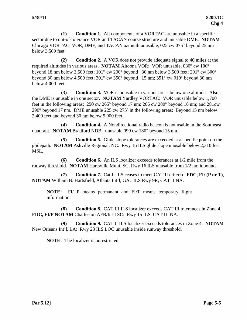
5/30/11 8200.1C Chg 4
Par 5.12j Page 5-5
(1) Condition 1. All components of a VORTAC are unusable in a specific sector due to out-of-tolerance VOR and TACAN course structure and unusable DME. NOTAM Chicago VORTAC: VOR, DME, and TACAN azimuth unusable, 025 cw 075 beyond 25 nm below 3,500 feet.
(2) Condition 2. A VOR does not provide adequate signal to 40 miles at the required altitudes in various areas. NOTAM Altoona VOR: VOR unusable, 080 cw 100 beyond 18 nm below 3,500 feet; 101 cw 200 beyond 30 nm below 3,500 feet; 201 cw 300 beyond 30 nm below 4,500 feet; 301 cw 350 beyond 15 nm; 351 cw 010 beyond 30 nm below 4,000 feet.
(3) Condition 3. VOR is unusable in various areas below one altitude. Also, the DME is unusable in one sector. NOTAM Yardley VORTAC: VOR unusable below 1,700 feet in the following areas: 250 cw 265 beyond 17 nm; 266 cw 280 beyond 10 nm; and 281cw 290 beyond 17 nm. DME unusable 225 cw 275 in the following areas: Beyond 15 nm below 2,400 feet and beyond 30 nm below 5,000 feet.
(4) Condition 4. A Nondirectional radio beacon is not usable in the Southeast quadrant. NOTAM Bradford NDB: unusable 090 cw 180 beyond 15 nm.
(5) Condition 5. Glide slope tolerances are exceeded at a specific point on the glidepath. NOTAM Ashville Regional, NC: Rwy 16 ILS glide slope unusable below 2,310 feet MSL.
(6) Condition 6. An ILS localizer exceeds tolerances at 1/2 mile from the runway threshold. NOTAM Hartsville Muni, SC, Rwy 16 ILS unusable from 1/2 nm inbound.
(7) Condition 7. Cat II ILS ceases to meet CAT II criteria. FDC, FI/ (P or T), NOTAM William B. Hartsfield, Atlanta Int’l, GA: ILS Rwy 9R, CAT II NA.
NOTE: FI/ P means permanent and FI/T means temporary flight information.
(8) Condition 8. CAT III ILS localizer exceeds CAT III tolerances in Zone 4.
FDC, FI/P NOTAM Charleston AFB/Int’l SC: Rwy 15 ILS, CAT III NA.
(9) Condition 9. CAT II ILS localizer exceeds tolerances in Zone 4. NOTAM New Orleans Int’l, LA: Rwy 28 ILS LOC unusable inside runway threshold.
NOTE: The localizer is unrestricted.

8200.1C 5/30/11 Chg 4
Page 5-6 Par 5.12j
(10) Condition 10. CAT III ILS localizer exceeds tolerances in Zone 5. NOTAM New Orleans Int’l, LA: Rwy 28 ILS LOC unusable for rollout guidance.
(11) Condition 11. Glide slope does not meet change/ reversal tolerances below a point on the glidepath. NOTAM Ashville Regional, NC: Rwy 16, autopilot coupled approaches NA below 2,000 feet MSL.
(12) Condition 12. Localizer does not meet tolerances in the vertical plane. NOTAM Wellsville Municipal Arpt., Tarantine Field Arpt., Wellsville, NY: ELZ LOC Rwy 28, LOC unusable beyond OM above 3,500, at threshold above 500.
(13) Condition 13. Beyond 5 left of LOC course, there are no glide slope clearances above path, and a glidepath is not provided. NOTAM Charlotte/ Douglas Int’l, NC: Rwy 36R ILS glide slope unusable beyond 5 left of LOC course.
(14) Condition 14.
(a) MLS Azimuth Unusable. Because an unusable approach azimuth renders the elevation unusable, refer to any unusable azimuth segment as “MLS unusable”. Describe the limits using inbound courses; e.g.:
1 UMP MLS unusable 196 cw 206.
2 UMP MLS unusable 196 cw 206 below 4.
3 UMP MLS unusable 196 cw 206 beyond 15 DME below 4,000 feet MSL.
(b) Elevation. Refer to any unusable segment as “MLS elevation unusable”; e.g.,
1 UMP MLS elevation unusable 151 cw 156 below 3.5.
2 UMP MLS elevation unusable 151 cw 156 beyond 15 DME below 7,000 feet MSL.
(c) MLS DME unusable. Refer to any area of unusable DME as “UMP MLS DME unusable”.
(15) Condition 15. PAPI lights are baffled and unusable beyond 5 right of centerline due to obstructions: NOTAM Heber City-Russ McDonald Fld, UT, RWY 21 PAPI unusable beyond 5 right of runway centerline.
k. Required Advisories for Local NOTAM(s). The flight inspector must notify Air Traffic (AT) personnel when the facility is not authorized for use because of flight inspection
actions.
02/01/07 8200.1C CHG 1
Par 5.20 Page 5-7
SECTION 2. RECORDS AND REPORTS 5.20 INTRODUCTION. This section provides policy for flight inspection reports and records. The flight inspection report provides permanent, historical interpretation of a system’s performance. The report must accurately reflect the operational status of the system, the quality of the signal in space, the instrument flight procedure, and revised obstacle, topographical, and cultural data. 5.21 RECORDS. Flight inspection files are Federal record material. The standards for their retention and destruction are contained in FAA Order 1350.15, Records Organization, Transfer, and Destruction Standards. A facility Reconfiguration (Special/ RF) inspection that meets all the commissioning requirements is considered a Commissioning type inspection for record keeping purposes. Flight inspection reports and source material for reports on all electronically radiated facilities inspected constitute report files that must be archived. Such material must contain, but is not limited to, recorder charts showing facility data used, system status, and self-test results, receiver outputs, and crew inputs affecting measurements. Data logger files must be archived for all inspections utilizing AFIS conducted with a functioning data logger. A functioning data logger should be available prior to the inspection. When logger files are not available for archive, either due to none being recorded or data corruption post flight, state such in the Remarks block of the report. Other material may include data items which are necessary for flight inspection purposes, such as horizon profiles, site drawings, topographic charts, instrument approach/ departure procedure charts, photographs, electronic media, and data sheets, aircraft logbooks, VFR Chart field sheets, and obstacle records. PAR, VGSI, and NDB source material is not required to be retained once the report has been archived.
a. General Information. Ensure that any information that is included in the facility file is annotated with the following information:
(1) Facility identification/type of facility
(2) Date(s) of inspection
(3) Type of inspection (e.g., periodic)
(4) Aircraft tail number
(5) Crew initials and numbers
(6) Recorder calibration
(7) Equipment-required flight inspection self-test
(8) Airborne flight inspection system calibrations (i.e., TVPS, and system setup)
b. Facility Data Sheets. The flight inspector must ensure that the facility data
reflects the most current information and is sufficient to complete the flight check requirements.
8200.1C 02/01/07 CHG 1
Page 5-8 Par 5.22
5.22 REPORTS. The flight inspection report serves as the primary means of documentation and dissemination of the results of each flight inspection. Requirements for the use, completion, and distribution of standard FAA and suitable military flight inspection forms are contained in FAA Order 8240.36, Flight Inspection Report Processing System (latest revision).
a. Military Facilities
(1) Changing a Facility Classification to Restricted or Unusable or Altering a Restriction. When the results of the flight inspection indicate that the facility classification is to be changed to "restricted" or "unusable" or that facility restrictions have changed, land the aircraft, if practical, and discuss the reasons and recommended action with appropriate representatives of the base commander. If it is impractical to land, give a status report to the control tower (on ground or tower frequency) indicating the exact status of the facility (unrestricted, restricted, or unusable) and all discrepancies found. Provide them with suggested wording for any required NOTAM(s). Request acknowledgement of the information.
(2) Where there has been no change in facility performance, inform the
control tower (on ground or tower frequency) of the exact facility classification. Again, request acknowledgement.
(3) If a military installation does not have a control tower, attempt to pass
the information over any other available air-to-ground frequency that would ensure dissemination of the flight check results. If no appropriate air-to-ground frequency is available and it is impractical to land, telephone the appropriate personnel as soon as possible.
(4) In any of the above cases, inform the appropriate military maintenance
personnel of any discrepancies discovered, and the resulting facility classification.
b. Reports Submitted by Military Flight Inspectors
(1) Flight inspection reports of facilities inspected by military flight inspection crews, who have been delegated the authority for execution of the flight inspection mission, must be accepted by the FAA as official flight inspection reports.
(2) Military flight inspectors must assign a classification or status to those
facilities for which they have flight inspection responsibility.
NOTE: Coordination may be in the form of a letter of agreement or may be handled on a case-by-case basis. Coordination with AVN constitutes full flight inspection authority for the respective facility.
c. VFR Aeronautical Chart field sheet notes and obstacle evaluations are a record
of having performed the flight inspection and will be archived at NACO.

10/01/05 8200.1C
Page 6-i
CHAPTER 6. FLIGHT INSPECTION OF INSTRUMENT FLIGHT PROCEDURES
TABLE OF CONTENTS
Paragraphs Title Pages 6.10 INTRODUCTION.............................................................................6-1 6.11 PREFLIGHT REQUIREMENTS......................................................6-1 6.12 FLIGHT INSPECTION PROCEDURES..........................................6-2
a. Objective................................................................................6-2 b. Verification of Required Obstacle Clearance........................6-3 c. Ground Proximity Warning System Alerts (GPWS).............6-4 d. RADAR Altimeter.................................................................6-4 e. Restricted NAVAID ..............................................................6-4 f. Distance Measuring Equipment (DME)................................6-4 g. Weather Requirements ..........................................................6-4
6.13 CHECKLIST .....................................................................................6-4 6.14 DETAILED PROCEDURES ............................................................6-5
a. Standard Instrument Departure (SID)/ Departure Procedure (DP) .....................................................6-5
b. En Route and Terminal Route Segments...............................6-5 c. Standard Terminal Arrival Route (STAR) ............................6-5 d. Standard Instrument Approach Procedures (SIAP(s)) ..........6-5 e. Flyability................................................................................6-5 f. Charted Visual Approaches...................................................6-6 g. Maximum Authorized Altitudes (MAA)...............................6-6 h. Holding Patterns ....................................................................6-7 i. Air/ Ground Communications ...............................................6-7 j. Runway Markings, Lighting, and Communication ...............6-7 k. RADAR Coverage.................................................................6-7 l. Periodic SIAP Reviews .........................................................6-7 m. Inspector Authority................................................................6-7
8200.1C 10/01/05
Page 6-ii
TABLE OF CONTENTS (continued)
Paragraphs Title Pages 6.15 ANALYSIS........................................................................................6-8
a. Cartographic Standards..........................................................6-8 b. Night Evaluations ..................................................................6-8 c. Human Factors.......................................................................6-8
6.16 TOLERANCES .................................................................................6-9
10/01/05 8200.1C
Par 6.10 Page 6-1
CHAPTER 6. FLIGHT INSPECTION OF INSTRUMENT FLIGHT PROCEDURES
6.10 INTRODUCTION. Instrument flight procedures specify standard routings, maneuvering areas, flight altitudes, and visibility minimums for instrument flight rules (IFR). These procedures include airways, jet routes, off-airway routes, Standard Instrument Approach Procedures (SIAP(s)), Standard Instrument Departure Procedures/ Departure Procedures (SID(s))/ DP(s)), and Standard Terminal Arrival Routes (STAR(s)). All new and revised procedures are subject to flight inspection. References in this chapter are for clarification purposes only and do not supersede instructions or flight inspection criteria for facilities or systems contained elsewhere in this order. 6.11 PREFLIGHT REQUIREMENTS
a. The office initiating the procedure must forward all data necessary for conducting the flight inspection to the Flight Inspection Central Office (FICO) who, in turn, will forward the information to the flight inspector responsible for the inspection. If there are special factors relative to the procedure, the FICO will set up a briefing by the procedures developer, or designee, for the flight inspector.
b. Procedural data must include the following as a minimum:
(1) Charts of sufficient detail to safely navigate and identify considerable terrain, obstacles, and obstructions;
(2) Controlling terrain/ obstructions identification for each segment;
(3) Minimum (and maximum where applicable) altitudes determined to be usable from map study and data base information for each segment of the procedure;
(4) Plan and profile views for SIAP(s);
(5) Data for each fix, intersection, waypoint, and holding pattern;
(6) Airport marking and any special local operational procedure (e.g., noise abatement, non-standard traffic patterns, lighting activation).
(7) Training, operational, or equipment procedure specific requirements.
8200.1C 10/01/05
Page 6-2 Par 6.11c
c. The procedure package must contain the minimum data to conduct a flight inspection. FAA 8260-XX forms should be used as a baseline for required information. Procedure packages with inadequate information will be returned to FICO, which will return it to the developing organization. The FICO/ flight inspector must identify deficiencies on a comment sheet to accompany the returned procedure package.
d. Applicable Navigation System Support. The variation in systems dictates a progressive approach in determining evaluation methods. Study of the procedure by the flight crew prior to flight will normally reveal the type of system(s) verification required. The flight inspector must verify the status of the appropriate ground-based and/ or space-based systems prior to flight. For complex procedures, additional flyability evaluations may be required in a proponent’s simulator or aircraft. 6.12 FLIGHT INSPECTION PROCEDURES
a. The objective of evaluating instrument flight procedures is to ensure safety, flyability, human factors, and workload. The following items are included in this evaluation:
(1) Procedure design meets the required obstacle clearance per applicable FAA 8260.XX orders or approved criteria.
(2) The applicable navigation system(s) (NAVAID, Satellite, RADAR, etc) supports the procedure.
(3) Procedure design must be simple. Chart complexity should be kept to a minimum for human memory considerations.
(4) Navigation charts must properly portray the procedure and be easily interpreted.
(5) Aircraft maneuvering must be consistent with safe operating practices for the category of aircraft intending to use the procedure.
(6) Cockpit workload is acceptable.
(7) Runway marking and lighting meet requirements.
(8) Communications are adequate.
(9) RADAR coverage is available, where required.
10/01/05 8200.1C
Par 6.12b Page 6-3
b. Verification of Required Obstacle Clearance
(1) Controlling obstacles in each segment must be confirmed by in-flight or ground observation during the commissioning of flight procedures. If unable to confirm that the declared controlling obstacle is the highest obstacle in the segment, list the location, type, and approximate elevation of the obstacles the flight inspector desires the procedure developer to consider. The flight inspector will place special emphasis on discovered obstacles that may not be listed in the FAA database. If the controlling obstacle is listed as terrain/ trees or Adverse Assumption Obstacle (AAO), it is not necessary to verify which tree is controlling, only that no higher man-made obstacle is present in the protected airspace. If the flight inspector observes that the controlling obstacle has been eliminated or dismantled, the flight inspector must forward that information to the procedure developer.
(2) Identification of New Obstacles. In most instances, accurate information concerning the location, description, and heights of tall towers and other considerable obstacles is available from the FAA database and/ or other government sources. When new potentially controlling obstructions not identified in the procedure package are discovered, the procedure commissioning will be denied until the procedure developer can analyze the impact of the obstacle on the overall procedure.
(a) Obstacle locations must be noted in latitude/ longitude, or radial/ bearing and distance from a known facility. If these methods are not available, an accurate description on the flight inspection map may be used.
(b) Obstacle heights measured in-flight will not be used unless the actual height of the obstruction cannot be determined by other means. If in-flight height determination is required, accurate altimeter settings and altitude references must be used to obtain precise results. The flight inspection report will reflect the documentation for the method of height determination.
(3) The controlling obstacle for initial approach segments of some RNAV procedures may also be the controlling obstacle for a large segment of the Terminal Arrival Area (TAA). The obstacle will not always be within the primary or secondary zones of the approach segment. Verify that there are no obstacles in the approach segments that are higher than the identified controlling obstacle. There is no requirement to verify that the identified controlling obstacle is the highest obstacle in the entire TAA segment, but, while transiting the segment, observe the area for obstacles that may exceed the height of the controlling obstacle.
8200.1C 02/01/07 CHG 1
Page 6-4 Par 6.12b
(4) The flight inspector retains the responsibility to ensure that the procedure is operationally safe. During obstacle verification inspections (other than commissioning inspections), it is not necessary to visually identify the controlling obstacle but rather to visually verify the integrity of the required obstacle clearance surface for the final and missed approach segments.
(5) Obstacle verification for a multiple of approaches to a runway may be completed during a single inspection to meet periodic requirements (i.e., KOKC ILS RWY 35R, ILS RWY 35R (CAT II), RNAV RWY 35R, NDB RWY 35R). Consideration must be given to the required obstacle clearance area for each approach and missed approach surface.
c. Ground Proximity Warning System Alerts (GPWS). Some GPWS(s) may alert while flying over irregular or rapidly rising terrain at altitudes providing standard obstacle clearance. If GPWS alerts are received while inspecting procedures, repeat the maneuver, ensuring flight at the designed true altitude. If the alert is repeatable, notify the procedure developer.
d. RADAR Altimeter. Category II/ III service requires the use of radio altimeter. Irregular terrain features could cause erratic radio altimeter indications. On commissioning or reconfiguration, report the radio altimeter indication at Category II Decision Height (DH). For periodic inspections, record the radio altimeter indications for engineering analysis purposes.
e. A restricted NAVAID may still support an instrument flight procedure when the procedure does not use the out-of-tolerance area. Facility restrictions affecting a procedure must be reflected on the flight inspection report.
f. A distance measuring equipment (DME) arc segment may be used in areas of unusable VOR radial information, provided that the DME, the radial where the arc starts, the lead radial, the final approach radial, and any other radial used in the procedure meet required tolerances. See Chapter 11 for TACAN tolerances.
g. The flight inspection of an instrument flight procedure or verification of the SIAP obstacle data may be conducted during the applicable system inspection if VMC prevail throughout each segment of the procedure to be evaluated. 6.13 CHECKLIST
Check Ref. Para. C P
Final Approach Segment 6.14 X X, 2 Missed Approach Segment 6.14 X X, 2 Circling Segment 6.14 X 1 En route and Terminal Segments (i.e., SID, DP, STAR) 6.14 X 1 Holding Pattern 6.14 X 1 Air/ Ground Communications 6.14 X 1 RADAR 6.14 X 1 Charted Visual 6.14 X Obstacle Verification 6.12 X X, 2
NOTE: 1. Surveillance 2. Public RNAV SIAP(s) have no periodic inspection requirement; however, a
periodic obstacle verification must still be completed for the runway(s) serviced.
10/01/05 8200.1C
Par 6.14 Page 6-5
6.14 DETAILED PROCEDURES. The flight inspector must evaluate all facets of the procedure to ensure compliance with safe operating practices. The evaluation must include the clarity and readability of the depiction. Workloads imposed on the aircrew to select or program the procedure must be reasonable and straightforward. Objective and professional judgment from aircrews trained in flight inspection is expected.
The requirements to evaluate signal quality are detailed in individual chapters. Requirements of this chapter are concerned with procedural aspects.
a. Standard Instrument Departure (SID)/ Departure Procedure (DP) procedures must be evaluated inflight to an established NAVAID, fix, or waypoint where en route obstacle clearance has been established. Evaluate the SID/ DP, using the minimum climb gradients and altitudes specified.
b. Airways, Routes, and Terminal Route Segments. Evaluate each airway, route, or terminal segment during commissioning flight inspection to ensure that the proposed minimum obstacle clearance altitude (MOCA) is adequate. Route segments must be flown at the proposed MEA (true altitude), using the applicable navigation system(s) for guidance and to or from a point where course or obstacle clearance has been established. The MEA and changeover points must be predicated on MOCA, minimum reception altitude (MRA), airspace, and communication requirements. If more than one of the above altitudes is procedurally required, the highest altitude determined through flight inspection will become the minimum en route altitude.
c. Standard Terminal Arrival Route (STAR) procedures must be evaluated to where the route intercepts a portion of an established SIAP or point from which a normal descent and landing can be accomplished.
d. Standard Instrument Approach Procedures (SIAP). All SIAP(s) intended for publication must be in-flight evaluated. Misalignment or inaccurate data indications will be forwarded to the procedure developer for further review prior to commissioning the procedure.
(1) Final Approach Segment. The final approach course must deliver the
aircraft to the desired aiming point. The aiming point varies with the type of system providing procedural guidance and will be determined by the procedure developer. After flight inspection verifies the aiming point, the course will not be changed without the concurrence of the procedure developer. When the system no longer delivers the aircraft to the established aiming point and the system cannot be adjusted to regain the desired alignment, consideration should be given to amending the procedure. The final approach segment must be flown to an altitude 100 ft below the proposed minimum descent altitude. Approaches with vertical guidance must be evaluated to the proposed decision or missed approach altitude.

8200.1C 10/01/05
Page 6-6 Par 6.14d
(2) Missed Approach. Flight inspection of the missed approach segment will assure that the procedure is safe and operationally sound for the category aircraft intended. When conducting periodic obstacle verification inspections, fly the missed approach procedure to a point where the flight inspector can identify any obstacles that could be a potential hazard.
(3) Circling. The flight inspector must verify that proposed circling maneuvers are safe and sound for the category of aircraft proposed. Circling maneuvers involving adverse obstructions/ terrain must be evaluated for day/ night operations and restricted if necessary.
(4) Visual Segment. Some procedures have extensive visual segments between the missed approach point and landing area. Evaluate these segments for operational suitability and safety. Recommend procedural adjustments when buildings or obstructions obscure access to the landing area. Procedures proposed for night use must be evaluated at night prior to commissioning.
e. Flyability. For procedures with a note stating “Applicable to Turbojet Aircraft Only”, an appropriately equipped turbojet flight inspection aircraft must be used for flyability evaluation. For complex procedures, additional flyability may be required in a proponent’s simulator or aircraft. Flyability must be evaluated with the aircraft coupled to the autopilot and may require additional evaluation by hand flying.
Vertical Flyability. Calculating Deceleration Segment Length Example: (may be applied to STAR or Initial/ Intermediate Approach Segments) An RNAV STAR begins at waypoint ALPHA at 17,000 MSL and 310 kts and requires the
aircraft to descent to and cross waypoint BRAVO at 9,000 MSL and 240 kts. The minimum leg length between ALPHA and BRAVO is computed as follows:
(17,000 – 9,000)/ 318 = Minimum leg length using a 3 descent gradient, 8,000/ 318 = 25.157 nm Plus (310 kts – 240 kts)/ 10 = Deceleration segment 70/ 10 = 7 nm 25.157 + 7 = 32.157 nm (round to 32.2 nm)
NOTE: Applicable TERPS criteria may allow for shorter deceleration segment.
f. Charted Visual Approaches. A commissioning check of charted visual
procedures is required. Determine flyability and ensure that depicted landmarks are visible in both day and night visual conditions. Flyability is determined by difficulty of aircraft placement, cockpit workload, landmark identification, location and visibility, and VFR obstacle clearance. A night evaluation must be completed prior to authorizing night use.
g. Maximum Authorized Altitudes (MAA). MAA(s) are limitations based on airspace restrictions, system performance characteristics, or interference predictions. If the MAA(s) are based on an interference problem, the source of the interference must be identified and corrective action initiated where possible.

10/01/05 8200.1C
Par 6.14j Page 6-7
h. Holding Patterns. Controlling obstacles must be verified to ensure the adequacy of minimum holding altitude (MHA). System performance will be evaluated to ensure conformance with appropriate tolerance chapters of this manual. If system performance and obstacle clearance data are on file, flight inspection of the procedure is not required.
i. Air/ Ground Communications. Air/ ground communications with ATC must be satisfactory at the initial approach fix (IAF) minimum altitude and at the missed approach altitude and holding fix. Satisfactory communications coverage over the entire airway or route segment at minimum en route IFR altitudes must be available with an ATC facility. Where ATC operations require continuity in communication coverage and ATC requests verification, flight inspection must evaluate that coverage in accordance with appropriate chapters of this order.
j. Runway Markings, Lighting, and Communication. The flight inspector must evaluate the suitability of the airport to support the procedure. Unsatisfactory or confusing airport markings, non-standard or confusing lighting aids, or lack of communication at critical flight phases may be grounds for denying the procedure. In all cases, the procedure developer will be apprised of the conditions discovered during the flight inspection.
k. RADAR Coverage. RADAR coverage must be verified for any procedure which requires RADAR.
l. Periodic SIAP Reviews. In addition to the in-flight evaluation of a SIAP during a periodic check, a detailed evaluation of each standard or special civil instrument approach procedure will be conducted to include at least the following: validity of altimeter setting source; validity of published notes; and a review of any published FDC NOTAM(s) on the approach procedure for currency and validity. The National Flight Procedures Office will be notified of any discrepancies found for possible NOTAM action and/ or correction, and documentation as a remark will be made on the applicable flight inspection report. A similar review of military instrument approach procedures with available information will be conducted. The appropriate military authorities will be notified of any discrepancies found and documentation as a remark will be made on the applicable flight inspection report.
NOTE: Instrument approach procedure discrepancies may not render a procedure unsafe or unusable; professional judgment and discretion in the evaluation of a procedure is expected.
m. Inspector Authority. At commissioning, the flight inspector has the discretion to
reject the procedure if it does not constitute a satisfactory maneuver from a human factors/ flyability standpoint. Concerns must be resolved with procedure developer and/ or supervisory personnel prior to commissioning. During subsequent checks of a commissioned procedure, new obstruction and/ or signal problems constitute reason for a flight inspector to deny or modify a procedure by NOTAM. Human factors/ flyability concerns during subsequent checks must be resolved with the procedure developer and/or supervisory personnel before any changes are issued.
8200.1C 9/14/09 Chg 2
Page 6-8 Par 6.15
6.15 ANALYSIS. Flight inspection determines that the procedure is safe and flyable. If a new procedure is unsatisfactory, the flight inspector must coordinate with the procedure developer to determine the necessary changes. When an existing procedure is found unsatisfactory due to obstructions, navigation source, charting error, etc., initiate NOTAM action immediately and advise the procedure developer.
a. Cartographic Standards. Changes to cartographic standards are the responsibility of the Interagency Air Cartographic Committee and the Intra-Agency Committee for Flight Information. Recommendations for changes to these standards should be sent to the Office of Aviation System Standards, Flight Inspection Operations Division, AVN-200, for consolidation and forwarding to the appropriate committee.
b. Night Evaluations
(1) Procedures developed for airports with no prior IFR service and
procedures to newly constructed runways, and procedures to runways lengthened or shortened require a night flight inspection to determine the adequacy of airport lighting systems prior to authorizing night minimums.
(2) Inspect initial installation of approach light systems during the hours of darkness. Evaluate the light system for:
(a) Correct light pattern as charted. (b) Operation in the manner proposed (e.g., photocell, radio control); (c) Local lighting patterns in the area surrounding the airport do not
distract, confuse, or incorrectly identify the runway environment.
(3) Addition or reconfiguration of lights to an existing system already approved for IFR service.
(a) An approach lighting system requires a night evaluation. (b) A runway lighting system may be evaluated day or night. First time
installation of REIL systems should be evaluated at night to determine effectiveness.
c. Human Factors are concerned with optimizing the relationship between flight crews and their activities by systematic application of human sciences integrated within the framework of systems engineering. In the context of flight inspection, it is a question of whether a flight procedure is operationally safe, practical, and flyable for a minimally qualified sole pilot flying an aircraft with basic IFR instrumentation in instrument meteorological conditions using standard navigation charting.

10/01/05 8200.1C
Par 6.15c Page 6-9 (and 10)
The criteria used to develop instrument flight procedures represent many factors such as positioning requirements, protected airspace, system and avionics capabilities, etc. Sensory, perceptual, and cognitive restrictions historically have been incorporated in the criteria only to a limited extent (e.g., length of approach segments, descent gradients, turn angles). These are products of subjective judgments in procedure development and cartographic standards. It is incumbent upon the flight inspector to apply the principles of human factors and professional judgment when certifying an original or amended procedure. The following factors must be evaluated:
(1) Practical. The procedure should be practical. Segment lengths for approach and missed approach segments should be appropriate for the category of aircraft using the procedure. Procedures must not require excessive aircraft maneuvering to remain on lateral and vertical path.
(2) Complexity. The procedure should be as simple as possible. It should not impose an excessive workload on a sole pilot flying a minimally equipped aircraft.
(3) Interpretability
(a) The final approach course should be clearly identifiable, with the primary guidance system or NAVAID unmistakable;
(b) The procedure should clearly indicate which runway the approach
serves and indicate which runway(s) circling maneuvers apply to; (c) Fix naming must be readable and clearly understood. Fixes/
waypoints with similar sounding identifiers should not be used in the same procedure. (d) Areas not to be used for maneuvering must be clearly defined. (e) Significant terrain features must be displayed on approach charts. (f) Operations into a “black hole” effect should be noted.
(4) Human Memory Considerations. Pilots must be able to extract
information quickly and accurately during an instrument approach. Multiple tasks complicate the memory process and tend to produce prioritization during stressful phases of flight. Workload reduction can be accomplished through methodical chart layout that encourages the pilot to periodically refer to the depicted procedure rather than trying to memorize complex maneuvers.
6.16 TOLERANCES. The procedure must be safe, practical, flyable, and easily interpreted with minimal additional cockpit workload. Supporting facilities/ systems must meet tolerances of the appropriate chapters of this manual and not contribute to operational confusion.


11/01/10 8200.1C Chg 3
Page 7-i
CHAPTER 7. LIGHTING SYSTEMS
TABLE OF CONTENTS Paragraphs Title Pages
SECTION 1. VISUAL GLIDE SLOPE INDICATOR (VGSI)
7.10 INTRODUCTION.........................................................................................7-1 a. Visual Approach Slope Indicator System (VASI).............................7-1 b. Precision Approach Path Indicator System (PAPI)...........................7-3 c. Pulsating Visual Approach Slope Indicator System (PVASI) ..........7-3 d. T-VASI ..............................................................................................7-4 e. Helicopter Approach Path Indicator (HAPI).....................................7-4 f. Tri-Color VASI .................................................................................7-4
7.11 PREFLIGHT REQUIREMENTS..................................................................7-4
a. Ground...............................................................................................7-4 b. Air......................................................................................................7-4
7.12 FLIGHT INSPECTION PROCEDURES......................................................7-4
a. Checklist ............................................................................................7-5 b. Detailed Procedures...........................................................................7-5
(1) Light Intensity .......................................................................7-5 (2) Glidepath Angle.....................................................................7-6 (3) Angular Coverage..................................................................7-7 (4) Obstruction Clearance ...........................................................7-8 (5) System Identification/Contrast ..............................................7-9 (6) Radio Control ........................................................................7-9 (7) Coincidence (ILS/ MLS/ PAR/ LAAS/ WAAS)...................7-10
7.13 ANALYSIS ...................................................................................................7-10 7.14 TOLERANCES .............................................................................................7-11
a. Light Intensity ...................................................................................7-11 b. Visaul Glidepath Angle .....................................................................7-11 c. Angular Coverage..............................................................................7-11 d. Obstacle Clearance ............................................................................7-11 e. Airfield/ System Contrast ..................................................................7-11
7.15 ADJUSTMENTS...........................................................................................7-11
8200.1C 10/01/05
Page 7-ii
Figures
Figure 7-A VASI-2....................................................................................................... 7-12 Figure 7-B VASI-4 System Layout.............................................................................. 7-12 Figure 7-C VASI-12 System Layout............................................................................ 7-12 Figure 7-D Aiming and Obstruction Clearance Diagram for 2-Bar VASI .................. 7-13 Figure 7-E System Layout, Walker 3-Bar VASI (VASI-6)......................................... 7-14 Figure 7-F System Layout, Walker 3-Bar VASI ......................................................... 7-14 Figure 7-G Aiming and Obstruction Clearance Diagram for Walker 3-Bar VASI...... 7-15 Figure 7-H PAPI Approach Path (Side View) ............................................................. 7-16 Figure 7-I PAPI........................................................................................................... 7-17 Figure 7-J PVASI Approach Path (Side View) .......................................................... 7-18 Figure 7-K T-VASI’s ................................................................................................... 7-19 Figure 7-L HAPI .......................................................................................................... 7-20
SECTION 2. APPROACH AND RUNWAY LIGHTS
7.20 INTRODUCTION ................................................................................................... 7-21 a. Approach Lighting System, Sequenced Flashers, (ALSF-1) ...................... 7-21
b. Approach Lighting System, Sequenced Flashers (ALSF-2) ....................... 7-21
c. Sequenced Flashers for ALSF-1 and ALSF-2 ............................................. 7-22
d. Simplified Short Approach Lighting System (SSALS)............................... 7-22
e. Simplified Short Approach Lighting System with Sequenced Flashers (SSALF).............................................................. 7-22
f. Simplified Short Approach Light System with Runway Alignment Indicator Lights (SSALR) ........................................... 7-22
g. Medium Intensity Approach Lighting System (MALS).............................. 7-22
h. Medium Intensity Approach Lighting System with Sequenced Flashers (MALSF)..................................................................... 7-22
i. Medium Intensity Approach Lighting System with Runway Alignment Indicator Lights (MALSR).......................................... 7-22
j. Omni-directional Approach Lighting System (ODALS) ............................ 7-23
k. Runway End Identifier Lights (REIL)......................................................... 7-23
l. Sequence Flashing Lights (SFL)/ Runway Alignment Indicator Lights (RAIL) .............................................. 7-23
7.21 PRE-FLIGHT REQUIREMENTS........................................................................... 7-23
a. Facilities Maintenance................................................................................. 7-23 b. Air ................................................................................................................ 7-23

02/01/07 8200.1C CHG 1
Page 7-iii (and iv)
7.22 FLIGHT INSPECTION PROCEDURES......................................................7-24 a. Checklist ............................................................................................7-24 b. Detailed Procedures...........................................................................7-24 c. Approach Light Systems ...................................................................7-25 d. Runway End Identifier Lights ...........................................................7-26
7.23 FLIGHT INSPECTION ANALYSIS............................................................7-26 7.24 TOLERANCES .............................................................................................7-27
a. Approach Lighting Systems, Runway Edge Lights, Touchdown Zone, and Runway Centerline Lights............................7-27
b. Runway End Identifier Lights (REIL)...............................................7-28 7.25 ADJUSTMENTS...........................................................................................7-28
Figures
Figure 7-M Runways With Approach Lights ...........................................7-25 Figure 7-N Runways Without Approach Lights ......................................7-26 Figure 7-O Lighting System Configurations............................................7-29 Figure 7-P Lighting System Configurations, Continued.........................7-30

This Page Intentionally Left Blank

10/01/05 8200.1C
Par 7.10 Page 7-1
CHAPTER 7. LIGHTING SYSTEMS
SECTION 1. VISUAL GLIDE SLOPE INDICATOR (VGSI) 7.10 INTRODUCTION. The Visual Glide Slope Indicators (VGSI) are ground devices that use lights to define a vertical approach path during the final approach to a runway. The visual signal must consist of not less than two and not more than four colors. Allowable colors are red, amber, green, or white. Color sectors must be distinct and identifiable throughout the horizontal beam width at all intensity settings. Only red is used to indicate the lowest below-path sector of the system. The final approach area for VGSI(s) is 10 either side of the runway centerline extended, measured from the forward most bar or light extending from the threshold outward to a point a normal glidepath can commence from the en route or procedural altitude. VGSI(s) are aligned to provide a glidepath not less than 1.0 above obstacles 10 either side of the runway centerline to a distance specified for the system, usually 4 miles. Lateral guidance is obtained by reference to either visual cues or electronic aids.
Threshold crossing height (TCH) is the height of the lowest on-path signal at the threshold. The minimum TCH is determined by the most critical aircraft that normally operates on the runway. The TCH of VGSI(s) will normally be 25 to 75 ft. Specific TCH criteria for each type system is located in FAA Order 6850.2, Visual Guidance Lighting Systems.
Box Identification. The U.S. practice, as found in FAA Order 6850.5, Maintenance of Lighted Navigational Aids, is that individual VASI or PAPI light boxes are numbered starting at (1), with the box nearest the runway on each side and working outboard. ICAO Annex 14 and Aerodrome Design Manual reverse this, and number or letter the boxes starting with (1) or (A) at the outermost box and working toward the runway. There are several different types of VGSI(s). The primary systems covered in this chapter are visual approach slope indicators (VASI), precision approach path indicators (PAPI), pulsating visual approach slope indicators (PVASI), T-VASI, three-color VASI, and helicopter approach path indicator (HAPI). Each of these systems presents a different type of visual indication to the pilot and requires different in-flight interpretation.
a. Visual Approach Slope Indicator System (VASI)
(1) The VASI consists of either two or three light bars placed perpendicular to the runway. The light bars consist of one, two, or three boxes aligned on the left or both sides of the runway. Each box contains three high intensity lamps behind a horizontally divided filter with red colored and clear portions.

8200.1C 10/01/05
Page 7-2 Par 7.10a
(2) In using the systems, a pilot should fly through the light bar nearest the runway threshold (number 1 bar) until it appears WHITE, and undershoot the light bar beyond the touchdown point (number 2 bar) until it appears RED. The aircraft will be on the visual glide slope when the number 2 light bar appears RED and the number 1 light bar appears WHITE. When the aircraft deviates from visual glidepath, the pilot will see a change in color of one of the light bars. Deviation above the established glidepath will cause the number 2 light bar to fade from RED, through PINK, to WHITE, with the total change occurring within 1/4 to 1/2. Deviation below the glidepath will cause the number 1 light bar to change from WHITE, through PINK, to RED, within 1/4 to 1/2. A pilot sees two WHITE bars above glidepath and two RED bars below glidepath. (See Figures 7-D and G.)
(3) The basic configurations of VASI are described below:
(a) Left Side of Runway.
1 VASI-2 consists of two light boxes as shown in Figure 7-A. This system provides descent information under daytime conditions to a distance of 3 miles.
2 Simplified Abbreviated Visual Approach Slope Indicator
System (SAVASI-2) consists of two light boxes with a single lamp in each box as shown in Figure 7-A. This system is designed for nonjet, utility runways, and provides descent information under daytime conditions to a distance of 1.5 miles.
3 VASI-4 consists of four light boxes installed as shown in
Figure 7-B. This system provides descent information under daytime conditions to a distance of 4 miles.
4 Walker 3-Bar VASI-6 is a 3-bar system installed as shown in
Figure 7-E. Each bar consists of two light boxes aligned on the left side of the runway. The system provides descent information under daytime conditions to a distance of 3 miles.
(b) Both Sides of Runway.
1 VASI-12 consists of 12 light boxes installed as shown in Figure 7-C. This system provides descent information under daytime conditions to a distance of 5 miles.
2 VASI-8 consists of eight light boxes installed as shown in
Figure 7-C. This system is basically the 12-box system with the outer four boxes removed and provides descent information under daytime conditions to a distance of 5 miles.

10/01/05 8200.1C
Par 7.10a Page 7-3
3 Walker 3-Bar VASI-16 consists of 16 light boxes installed as shown in Figure 7-F. The system is basically a VASI-12 with the addition of an upwind 2-box light bar on each side of the runway. This provides an additional visual glidepath above and almost parallel to the normal path. The upper path is designed for high cockpit aircraft, ensuring a safe minimum wheel clearance over the runway threshold. This system provides descent information under daytime conditions to a distance of 5 miles.
b. Precision Approach Path Indicator System (PAPI)
(1) The PAPI uses a two-color light projector system that produces a visual
glidepath as shown in Figure 7-H. Each light box consists of at least two optical projectors that produce a single beam of light, the upper part of the beam is WHITE and the lower part RED. When passing through the beams, the transition from one color to the other is almost instantaneous.
(2) There are two basic configurations of PAPI(s) that are described
below:
(a) Four-Box System. The glidepath angle of a 4-box system is the midpoint of the angular setting of the center pair of light boxes. The on-path width is the difference between the angles of light boxes 2 and 3. Normal installation requires 0.33 between light box settings 1 and 2, 2 and 3, and 3 and 4. Systems that support large aircraft require 0.50 between light boxes 2 and 3. The on-glidepath indication is two RED and two WHITE lights on the light bar. When the aircraft goes below the glidepath, the pilot sees a progressively increasing number of RED lights, and if the aircraft goes above the glide slope, the number of WHITE lights increases as shown in Figure 7-I. This system provides descent information under daytime conditions to a distance of 4 miles.
(b) Two-Box System. This system is designed for utility type runways.
The glidepath angle is the midpoint between the angular setting of the two light boxes. The on-path width of this system is normally 0.50, but may be reduced to provide obstacle clearance. The on-glidepath indication is one RED and one WHITE light. When the aircraft goes below the glidepath, the pilot sees two RED lights and two WHITE lights above glidepath. This system provides descent information under daytime conditions to a distance of 2 miles.
(c) Installation Convention. The system is normally installed on the left
side of the runway but may be on the right or on both sides as shown in Figure 7-I.
c. Pulsating Visual Approach Slope Indicator System (PVASI). PVASI(s) normally consist of a single light unit projecting a two-color visual approach path as shown in Figure 7-J. The below glidepath indication may be pulsating or steady RED, and the above glidepath indication is normally pulsating WHITE. The above and below path pulsating lights appear to pulse faster the farther off path the pilot flies. The on-glide-path indication for one system is a steady WHITE light, and for another system the on-glide-path indication is an alternating RED and WHITE light. The on-path width of the steady WHITE light is approximately 0.35 wide. This system provides descent information under daytime conditions to a distance of 4 miles.

8200.1C 10/01/05
Page 7-4 Par 7.10d
d. T-VASI. The T-VASI presents a T-shaped light configuration as shown in Figure 7-K. The standard version has 10 lights on each side of the runway; the abbreviated AT-VASI is installed on only one side. If the aircraft is above the path, the vertical ‘stem’ of the T appears inverted above the horizontal path. The length of the stem is relative to the amount the aircraft is above the angle. As the aircraft nears the glide angle, the stem length decreases until it is not visible at the glide angle. As the aircraft goes below the glide angle, the stem of the T appears below the horizontal lights. When the aircraft reaches 1.9, the lights turn RED, indicating well below glide path. When above the path, the fly-up lights should not be visible, and when below the path, the fly-down lights should not be visible.
e. Helicopter Approach Path Indicator (HAPI). The HAPI system, as shown in Figure 7-L, provides angular indications by changing light color between red and green and by pulsing the light. The on-path indication is a steady green light and, as the angle increases, the light flashes at a rate of at least 2 Hz. The slightly below path indication is a steady red indication, which turns to a flashing red indication at well below path. The width of the on-path should be 0.75, and the width of the slightly below indication should be 0.25.
f. Tri-Color VASI. The tri-color VASI (TRCV) is a single steady light that appears to change color in relation to the observer’s angle. The on-path indication is a steady GREEN light, and the above path indication is AMBER. As the aircraft goes below path, a RED indication, sometimes preceded by a DARK AMBER, is seen.
7.11 PREFLIGHT REQUIREMENTS
a. Ground. In addition to preparations specified in Chapter 4, Section 3, the Facilities Maintenance personnel must:
(1) Ensure that all lamps are operating.
(2) Check the lamps for blackening and the lenses for cleanliness.
(3) Check the setting of each box to determine proper angular adjustment.
(4) Inform the flight inspection personnel of any unique siting conditions such as visual screening, waivers, or local restrictions.
b. Air. The flight inspector will comply with the preparations specified in Chapter 4,
Section 3. 7.12 FLIGHT INSPECTION PROCEDURES. Initial settings are determined by ground adjustments and verified by flight inspection. Flight inspection checks the overall appearance and usability of the system as viewed by the pilot on the approach, checks for coincidence of the VGSI(s) with other NAVAID(s) serving the same runway, and confirms obstacle clearance. If the flight inspection effective glidepath angle is found out of tolerance IAW Paragraph 7.14b, the VGSI vertical alignment angles may be adjusted beyond Order 6850.5, Maintenance of Lighted Navigational Aids, tolerances to satisfy flight inspection results. These reference settings will be the basis for all future VGSI vertical alignments. Some of the detailed procedures below are type specific; adaptation of these procedures may be required for new or modified equipment types.

9/14/09 8200.1C Chg 2
Par 7.12a Page 7-5
a. Checklist. A commissioning inspection is required for all new VGSI(s) with an associated IFR procedure (to include circling approaches). Many existing VGSI(s) were placed into service without flight inspection; they may remain in service without a commissioning-type inspection until reconfigured to new systems or the addition of electronic vertical guidance to that runway. Specific VGSI facility data IAW FAA Order 8240.52, Aeronautical Data Management, is required for any VGSI inspection except Surveillance. Do not attempt to conduct the inspection using data from other facilities on that runway, e.g., ILS data.
Type Check Ref
eren
ce
Par
agra
ph
C
Light Intensity 7.12b(1) X Glidepath Angle 7.12b(2) X Angular Coverage 7.12b(3) X Obstruction Clearance 7.12b(4) X System Identification/ Contrast 7.12b(5) X Radio Control 7.12b(6) X Coincidence with electronic glidepath 7.12b(7) X
NOTE: There is no periodic inspection requirement for VGSI facilities. However, surveillance of safe operation will be accomplished in conjunction with other flight inspections involving the associated runway.
b. Detailed Procedures
(1) Light Intensity
(a) General. Depending on the type of VGSI(s) and system design, the
light intensity can be either manually or automatically controlled for daylight or darkness operations Some systems have three settings which allow for daylight, twilight, and dark operations. Maintenance can select one or two options for night operations to accommodate local site conditions for some systems.
8200.1C 11/01/10 Chg 3
Page 7-6 Par 7.12b
(b) Positioning. For facilities that are manually controlled, fly inbound while the controller changes the intensity settings to all operating ranges. Systems that use the automatic intensity settings should be checked the same as the manually controlled systems, if a method of changing the intensity is available. Intensity should be observed throughout the flight inspection.
(c) Evaluation. Ensure all lamps are operating and are at the same
relative intensity for each setting. If possible, the flight inspection should not be made during bright sunlight as it will reduce the effectiveness of the VGSI(s). The normal intensity setting for daylight operation is 100 percent, for twilight periods 30 percent, and for hours of darkness 10 percent.
(2) Glidepath Angle
(a) General. VGSI(s) provide vertical guidance for a VFR approach or
for the visual portion of an instrument approach. The angle established by the VGSI(s) is referred to as the visual glidepath angle. The signal formats used to establish the visual glidepath angle can vary from a single light source, two or three light sources in a longitudinal array, and four or more light sources in a lateral and/or longitudinal array. Setting the required visual angle is a function of ground installation personnel. (See Figures 7-D and G.)
(b) Positioning
1 Level Run Method. Position the aircraft inbound on the
runway centerline in the below path sector at an altitude that will intercept the light pattern within a distance at which it can be clearly seen. Proceed inbound in level flight at the slowest practical speed.
2 On-Path Method. Position the aircraft inbound on the runway centerline in the below path sector at the procedural intercept altitude or 1,000 ft AGL, whichever is higher. Upon reaching the glidepath indications, begin a descent and keep the aircraft in the center of the on-glidepath indication.
3 Theodolite Positioning. Position the theodolite beside the runway so the imaginary glidepath, originating from a point abeam the runway reference point (RRP), will pass through the theodolite eyepiece. The RRP is the point on the runway where the visual glidepath intercepts the surface.
(c) Evaluation
1 The Level Run Method may be used to determine the path angle of all VGSI types. Average the results of at least two runs for commissioning-type inspections. Keeping a constant altitude and airspeed, the flight inspector marks the appropriate indications for the VGSI type.
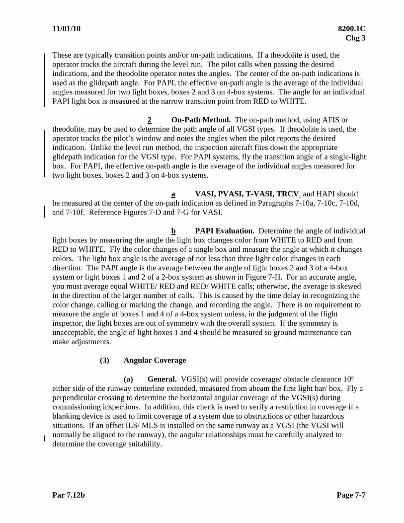
11/01/10 8200.1C Chg 3
Par 7.12b Page 7-7
These are typically transition points and/or on-path indications. If a theodolite is used, the operator tracks the aircraft during the level run. The pilot calls when passing the desired indications, and the theodolite operator notes the angles. The center of the on-path indications is used as the glidepath angle. For PAPI, the effective on-path angle is the average of the individual angles measured for two light boxes, boxes 2 and 3 on 4-box systems. The angle for an individual PAPI light box is measured at the narrow transition point from RED to WHITE.
2 On-Path Method. The on-path method, using AFIS or theodolite, may be used to determine the path angle of all VGSI types. If theodolite is used, the operator tracks the pilot’s window and notes the angles when the pilot reports the desired indication. Unlike the level run method, the inspection aircraft flies down the appropriate glidepath indication for the VGSI type. For PAPI systems, fly the transition angle of a single-light box. For PAPI, the effective on-path angle is the average of the individual angles measured for two light boxes, boxes 2 and 3 on 4-box systems.
a VASI, PVASI, T-VASI, TRCV, and HAPI should be measured at the center of the on-path indication as defined in Paragraphs 7-10a, 7-10c, 7-10d, and 7-10f. Reference Figures 7-D and 7-G for VASI.
b PAPI Evaluation. Determine the angle of individual
light boxes by measuring the angle the light box changes color from WHITE to RED and from RED to WHITE. Fly the color changes of a single box and measure the angle at which it changes colors. The light box angle is the average of not less than three light color changes in each direction. The PAPI angle is the average between the angle of light boxes 2 and 3 of a 4-box system or light boxes 1 and 2 of a 2-box system as shown in Figure 7-H. For an accurate angle, you must average equal WHITE/ RED and RED/ WHITE calls; otherwise, the average is skewed in the direction of the larger number of calls. This is caused by the time delay in recognizing the color change, calling or marking the change, and recording the angle. There is no requirement to measure the angle of boxes 1 and 4 of a 4-box system unless, in the judgment of the flight inspector, the light boxes are out of symmetry with the overall system. If the symmetry is unacceptable, the angle of light boxes 1 and 4 should be measured so ground maintenance can make adjustments.
(3) Angular Coverage
(a) General. VGSI(s) will provide coverage/ obstacle clearance 10
either side of the runway centerline extended, measured from abeam the first light bar/ box. Fly a perpendicular crossing to determine the horizontal angular coverage of the VGSI(s) during commissioning inspections. In addition, this check is used to verify a restriction in coverage if a blanking device is used to limit coverage of a system due to obstructions or other hazardous situations. If an offset ILS/ MLS is installed on the same runway as a VGSI (the VGSI will normally be aligned to the runway), the angular relationships must be carefully analyzed to determine the coverage suitability.

8200.1C 11/01/10 Chg 3
Page 7-8 Par 7.12b
(b) Positioning. Check the angular coverage by crossing the extended runway centerline at a 90 angle at a sufficient distance to enable the flight inspector to observe any shielding effect on the system. Conduct the maneuver at an altitude which provides an on-path indication.
(c) Evaluation. Observe the point where the VGSI system becomes
usable or unusable. The usable area is the angular coverage. For a system installed on only one side to be considered usable, all lights must be visible. For dual side installations, coverage from either side is required.
(4) Obstruction Clearance
(a) General. The visual glidepath should be at least 1 above all obstacles in the final approach area. The VGSI(s) must provide clearance above all obstacles within the commissioned operational service volume. Figures 7-D/ G/ H/ J diagram the aiming of light boxes and installation obstruction clearance requirements for the different type VGSI systems. Flight inspection does not verify obstruction clearance as determined by site survey. It does verify that specific VGSI below path indications clear all obstacles within the commissioned operational service volume. The below-path approach is conducted during commissioning inspections and anytime there is a questionable obstruction to determine satisfactory guidance and obstruction clearances. When necessary, lateral coverage may be reduced for obstacles by the use of blanking devices or baffles.
(b) Positioning. Position the aircraft outside of the normal glide slope
intercept distance below the glidepath. While proceeding inbound, a definite below path indication must be visible on the VGSI(s) while maintaining clearance above all obstacles in the approach path.
(c) Evaluation. Make approaches on runway centerline extended and
along each side of the approach area from the point where the VGSI's angle intercepts 1,000 ft AGL or procedural altitude, whichever is higher. If the lateral coverage extremities can be checked for obstacle clearance while flying the runway centerline track, a single inbound run may be used. A definite climb indication must be evidenced by the system while maintaining clearance above all obstacles. If necessary, use a theodolite to verify a critical obstacle. The following climb indications must be visible while maintaining clearance above all obstacles:
1 VASI. A definite RED/ RED light must be visible on both upwind and downwind bars while maintaining clearance above all obstacles.
2 PAPI. A definite RED must be visible on all light boxes
while maintaining clearance above all obstacles. 3 PVASI/ HAPI. A definite flashing RED must be visible on
the light unit while maintaining clearance above all obstacles.
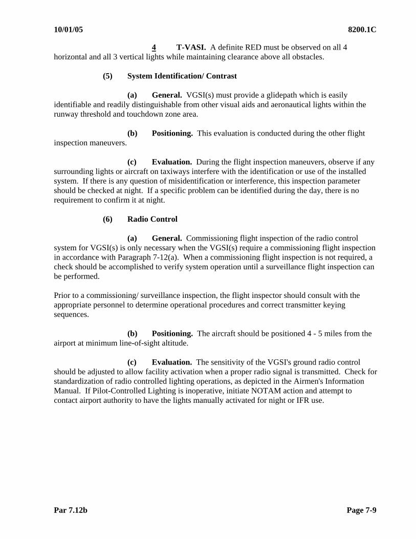
10/01/05 8200.1C
Par 7.12b Page 7-9
4 T-VASI. A definite RED must be observed on all 4 horizontal and all 3 vertical lights while maintaining clearance above all obstacles.
(5) System Identification/ Contrast
(a) General. VGSI(s) must provide a glidepath which is easily identifiable and readily distinguishable from other visual aids and aeronautical lights within the runway threshold and touchdown zone area.
(b) Positioning. This evaluation is conducted during the other flight
inspection maneuvers. (c) Evaluation. During the flight inspection maneuvers, observe if any
surrounding lights or aircraft on taxiways interfere with the identification or use of the installed system. If there is any question of misidentification or interference, this inspection parameter should be checked at night. If a specific problem can be identified during the day, there is no requirement to confirm it at night.
(6) Radio Control
(a) General. Commissioning flight inspection of the radio control
system for VGSI(s) is only necessary when the VGSI(s) require a commissioning flight inspection in accordance with Paragraph 7-12(a). When a commissioning flight inspection is not required, a check should be accomplished to verify system operation until a surveillance flight inspection can be performed.
Prior to a commissioning/ surveillance inspection, the flight inspector should consult with the appropriate personnel to determine operational procedures and correct transmitter keying sequences.
(b) Positioning. The aircraft should be positioned 4 - 5 miles from the
airport at minimum line-of-sight altitude.
(c) Evaluation. The sensitivity of the VGSI's ground radio control should be adjusted to allow facility activation when a proper radio signal is transmitted. Check for standardization of radio controlled lighting operations, as depicted in the Airmen's Information Manual. If Pilot-Controlled Lighting is inoperative, initiate NOTAM action and attempt to contact airport authority to have the lights manually activated for night or IFR use.

8200.1C 11/01/10 Chg 3
Page 7-10 Par 7.12b
(7) Coincidence (ILS/ MLS/ PAR/ LAAS/ WAAS).
(a) General. When VGSI(s) and electronic glide path information serve the same runway, the visual approach path will coincide with the one produced electronically. VGSI installations are engineered to provide close RRP coincidence with the RPI (ILS, MLS, PAR) or the GPI (LAAS, WAAS), using the same commissioned angle for both systems. Siting conditions affecting the electronic aid’s achieved RPI may result in achieved RPI/ RRP coincidence values beyond installation specifications, but satisfactory for use. Non-coincidence of angles and/or intercept points may be allowed, providing they are published as such. Approved waivers to electronic glide slopes must apply to VGSI systems.
1 Height Group 4. Some PAPI and PVASI are installed to serve aircraft in Height Group 4 (FAA Order 6850.2, Visual Guidance Lighting Systems). The RRP of these systems is engineered to be 300 – 350 ft down the runway from the electronic RPI. PAPI or PVASI sited to support height group 4 must be identified in Airport/ Facility Directories or similar publications.
2 Barometric Vertical Navigation (VNAV) Instrument
Procedures Development will cause VNAV path angles to be published on non-precision approaches. The published VNAV angle should be used for this comparison instead of flying the Baro-VNAV glidepath, because the actual aircraft in-flight path will vary with temperature. Whenever possible, the VGSI should be coincident with the published VNAV path angle; however, the approach types in Paragraph 7.12b(7)(a) above take precedence.
(b) Positioning. For systems installed to support aircraft in Height Groups 1, 2, and 3, fly the electronic glide slope from approximately 2 nm to threshold. For PAPI/ PVASI installed for Height Group 4, independently fly both the electronic and visual glide slopes. While flying the visual glide slope, monitor or record the ILS/ MLS glide slope for expected ILS/ MLS displacement at the 6,000 ft and 1,000 ft points.
(c) Evaluation. Compare the electronic and visual glide slopes in the
area between 6,000 ft and 1,000 ft prior to threshold for coincidence of runway point-of-intercept. For commissioning, both angles should be optimized if possible. For PAPI/ PVASI sited for Height Group 4 aircraft, compare the achieved runway intersection points of both systems. 7.13 ANALYSIS. Many factors, such as snow, dust, precipitation, color of background, terrain, etc., affect the pilot's color interpretation of the VGSI. Some deterioration of system guidance may occur as the pilot approaches the runway threshold due to the spread of light sources and narrowing of individual colors.
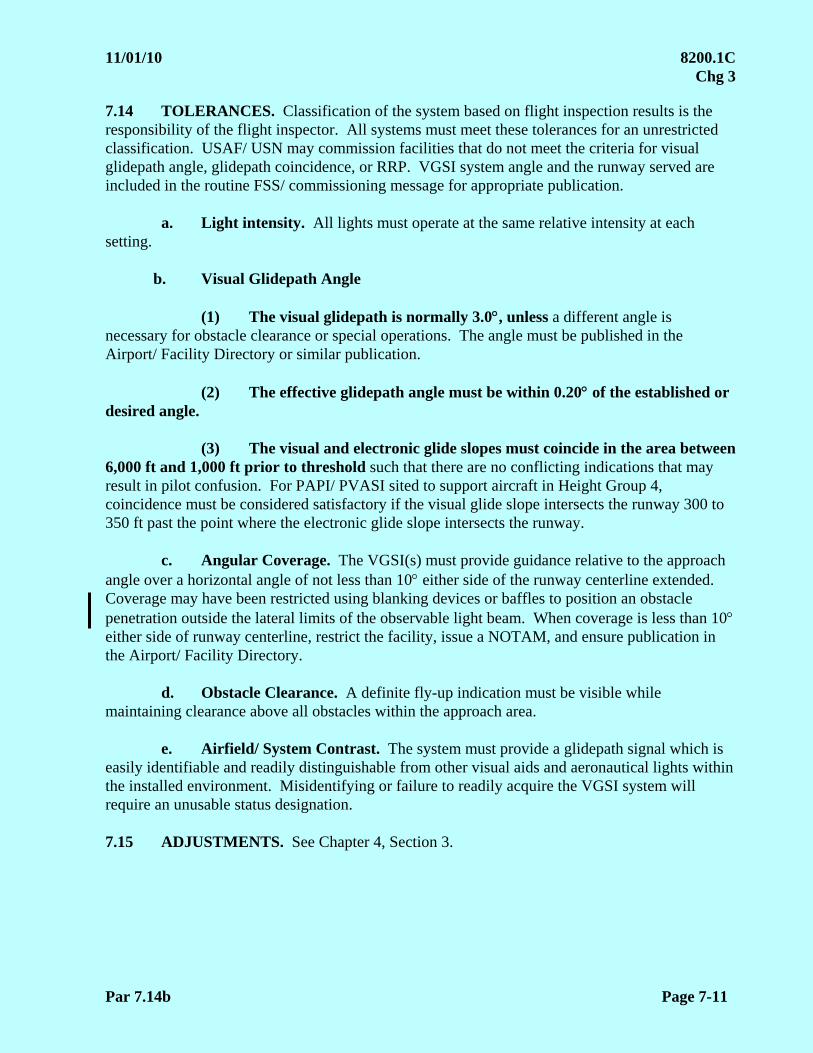
11/01/10 8200.1C Chg 3
Par 7.14b Page 7-11
7.14 TOLERANCES. Classification of the system based on flight inspection results is the responsibility of the flight inspector. All systems must meet these tolerances for an unrestricted classification. USAF/ USN may commission facilities that do not meet the criteria for visual glidepath angle, glidepath coincidence, or RRP. VGSI system angle and the runway served are included in the routine FSS/ commissioning message for appropriate publication.
a. Light intensity. All lights must operate at the same relative intensity at each setting.
b. Visual Glidepath Angle
(1) The visual glidepath is normally 3.0, unless a different angle is necessary for obstacle clearance or special operations. The angle must be published in the Airport/ Facility Directory or similar publication.
(2) The effective glidepath angle must be within 0.20 of the established or
desired angle.
(3) The visual and electronic glide slopes must coincide in the area between 6,000 ft and 1,000 ft prior to threshold such that there are no conflicting indications that may result in pilot confusion. For PAPI/ PVASI sited to support aircraft in Height Group 4, coincidence must be considered satisfactory if the visual glide slope intersects the runway 300 to 350 ft past the point where the electronic glide slope intersects the runway.
c. Angular Coverage. The VGSI(s) must provide guidance relative to the approach
angle over a horizontal angle of not less than 10 either side of the runway centerline extended. Coverage may have been restricted using blanking devices or baffles to position an obstacle penetration outside the lateral limits of the observable light beam. When coverage is less than 10 either side of runway centerline, restrict the facility, issue a NOTAM, and ensure publication in the Airport/ Facility Directory.
d. Obstacle Clearance. A definite fly-up indication must be visible while
maintaining clearance above all obstacles within the approach area. e. Airfield/ System Contrast. The system must provide a glidepath signal which is
easily identifiable and readily distinguishable from other visual aids and aeronautical lights within the installed environment. Misidentifying or failure to readily acquire the VGSI system will require an unusable status designation.
7.15 ADJUSTMENTS. See Chapter 4, Section 3.

8200.1C 10/01/05
Page 7-12 Fig 7-A
Fig
ure
7-C
V
AS
I-12
SY
ST
EM
LA
YO
UT
F
igu
re 7
-B
VA
SI-
4 S
YS
TE
M L
AY
OU
T
Fig
ure
7-A
V
AS
I-2
LAN
DIN
G
TH
RE
SH
OLD
NO
.1 B
AR
NO
. 2 B
AR
31
2
LAN
DIN
G
TH
RE
SH
OLD
NO
.1 B
AR
NO
. 2 B
AR
12
31
2
LAN
DIN
G
TH
RE
SH
OLD
NO
.1 B
AR
NO
. 2 B
AR
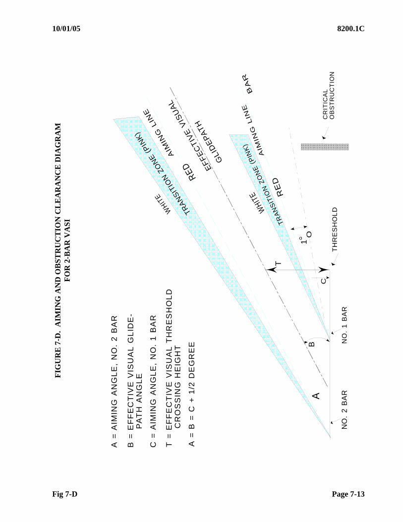
10/01/05 8200.1C
Fig 7-D Page 7-13
A=
AIM
ING
AN
GL
E,
NO
.2
BA
R
B=
EF
FE
CT
IVE
VIS
UA
LG
LID
E-
PA
TH
AN
GL
E
C=
AIM
ING
AN
GL
E,
NO
.1
BA
R
T=
EF
FE
CT
IVE
VIS
UA
LT
HR
ES
HO
LD
CR
OS
SIN
GH
EIG
HT
A=
B=
C+
1/2
DE
GR
EE
NO
.2
BA
RN
O.
1B
AR
TH
RE
SH
OL
DWH
ITE
GLI
DE
PA
TH
EF
FE
CT
IVE
VIS
UA
L
AIM
ING
LIN
E
AIM
ING
LIN
E
TR
AN
SIT
ION
ZO
NE
(PIN
K)
BA
R
WHI
TE
RE
D
RE
D
B
CR
ITIC
AL
OB
ST
RU
CT
ION
T
C
1O
TRA
NS
ITIO
NZO
NE
(PIN
K)
A
o
FIG
UR
E 7
-D.
AIM
ING
AN
D O
BS
TR
UC
TIO
N C
LE
AR
AN
CE
DIA
GR
AM
F
OR
2-B
AR
VA
SI
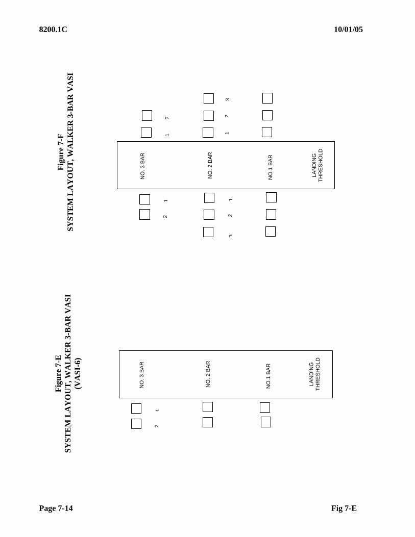
8200.1C 10/01/05
Page 7-14 Fig 7-E
12
31
2
LAN
DIN
G
TH
RE
SH
OLD
NO
.1 B
AR
NO
. 2 B
AR
12
3
12
NO
. 3 B
AR
LAN
DIN
G
TH
RE
SH
OLD
NO
.1 B
AR
NO
. 2 B
AR
NO
. 3 B
AR
12
Fig
ure
7-E
S
YS
TE
M L
AY
OU
T, W
AL
KE
R 3
-BA
R V
AS
I (V
AS
I-6)
Fig
ure
7-F
S
YS
TE
M L
AY
OU
T, W
AL
KE
R 3
-BA
R V
AS
I
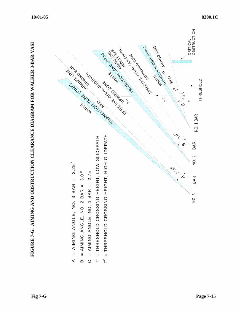
10/01/05 8200.1C
Fig 7-G Page 7-15
WHIT
E
TRANSITIO
NZONE
(PIN
K)
AIMIN
GLI
NE
UPW
IND
BAR
RED
EFFECTIVE
VISUAL
GLIDEPATH
UPWIN
DZONE W
HIT
E
TRAN
SITIO
NZO
NE
(PIN
K)
AIMIN
GLI
NE
MID
DLEBA
R
EFFEC
TIVE
VISU
ALG
LID
EPAT
H
TRA
NS
ITIO
NZO
NE
(PIN
K)
DO
WN
WIN
DZO
NE
WH
ITE
RE
D
AIM
ING
LIN
E
O
NO
.3N
O.
2B
AR
BA
RNO
.1BA
RT
HR
ES
HO
LD
AB
C3.
0o1o
2.7
5
2 1
CR
ITIC
AL
OB
ST
RU
CT
ION
C=
AIM
ING
AN
GL
E,
NO
.1
BA
R=
2.7
5
T T
3.25o
T=
TH
RE
SH
OL
DC
RO
SS
ING
HE
IGH
T,
LO
WG
LID
EP
AT
H
T=
TH
RE
SH
OL
DC
RO
SS
ING
HE
IGH
T,
HIG
HG
LID
EP
AT
H
B=
AIM
ING
AN
GL
E,
NO
.2
BA
R=
3.0
A=
AIM
ING
AN
GL
E,
NO
.3
BA
R=
3.2
5
o
o
1 2
FIG
UR
E 7
-G.
AIM
ING
AN
D O
BS
TR
UC
TIO
N C
LE
AR
AN
CE
DIA
GR
AM
FO
R W
AL
KE
R 3
-BA
R V
AS
I

8200.1C 10/01/05
Page 7-16 Fig 7-H
FIG
UR
E 7
-H P
AP
I A
PP
RO
AC
H P
AT
H (
SID
E V
IEW
)
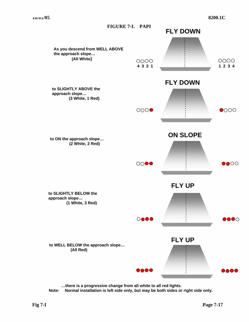
10/01/05 8200.1C
Fig 7-I Page 7-17
FIGURE 7-I. PAPI
As you descend from WELL ABOVE the approach slope… (All White)
to SLIGHTLY ABOVE the approach slope…
(3 White, 1 Red)
to ON the approach slope… (2 White, 2 Red)
to SLIGHTLY BELOW the approach slope… (1 White, 3 Red)
to WELL BELOW the approach slope… (All Red)
…there is a progressive change from all white to all red lights. Note: Normal installation is left side only, but may be both sides or right side only.
FLY DOWN
FLY DOWN
ON SLOPE
FLY UP
FLY UP
1 2 3 4 4 3 2 1
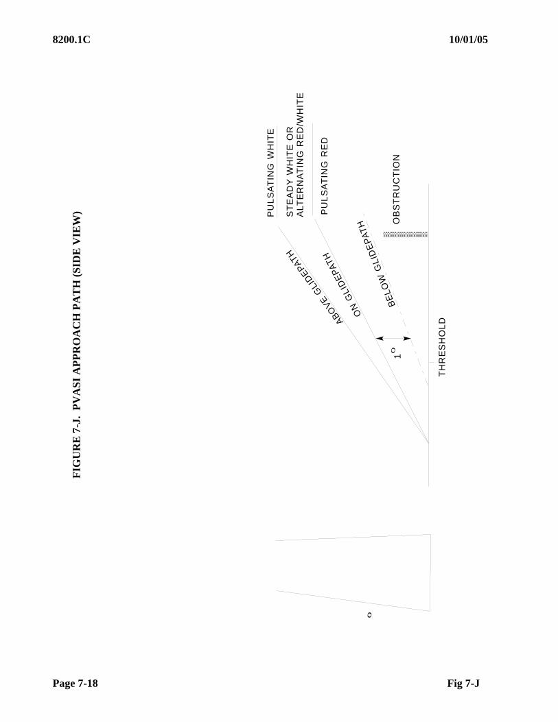
8200.1C 10/01/05
Page 7-18 Fig 7-J
AB
OV
EG
LID
EPA
TH
ON
GLI
DE
PA
TH
BE
LO
WG
LID
EP
AT
H
PU
LS
AT
ING
WH
ITE
PU
LS
AT
ING
RE
D
OB
ST
RU
CT
ION
TH
RE
SH
OL
D
ST
EA
DY
WH
ITE
OR
ALT
ER
NA
TIN
GR
ED
/WH
ITE
01
0
FIG
UR
E 7
-J.
PV
AS
I A
PP
RO
AC
H P
AT
H (
SID
E V
IEW
)
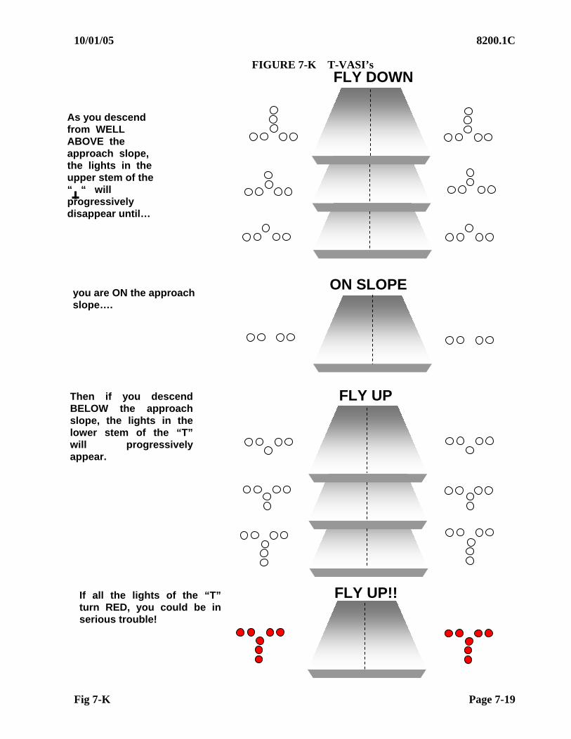
10/01/05 8200.1C
Fig 7-K Page 7-19
FIGURE 7-K T-VASI’s
FLY DOWN
ON SLOPE
FLY UP
FLY UP!!
As you descend from WELL ABOVE the approach slope, the lights in the upper stem of the “ “ will progressively disappear until…
you are ON the approach slope….
Then if you descend BELOW the approach slope, the lights in the lower stem of the “T” will progressively appear.
If all the lights of the “T” turn RED, you could be in serious trouble!
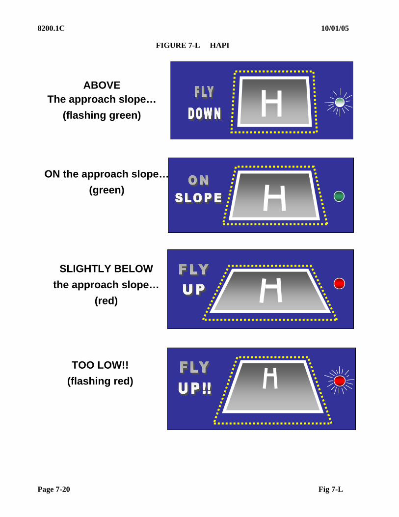
8200.1C 10/01/05
Page 7-20 Fig 7-L
FIGURE 7-L HAPI
ABOVE The approach slope…
(flashing green)
ON the approach slope…
(green)
SLIGHTLY BELOW
the approach slope…
(red)
TOO LOW!!
(flashing red)
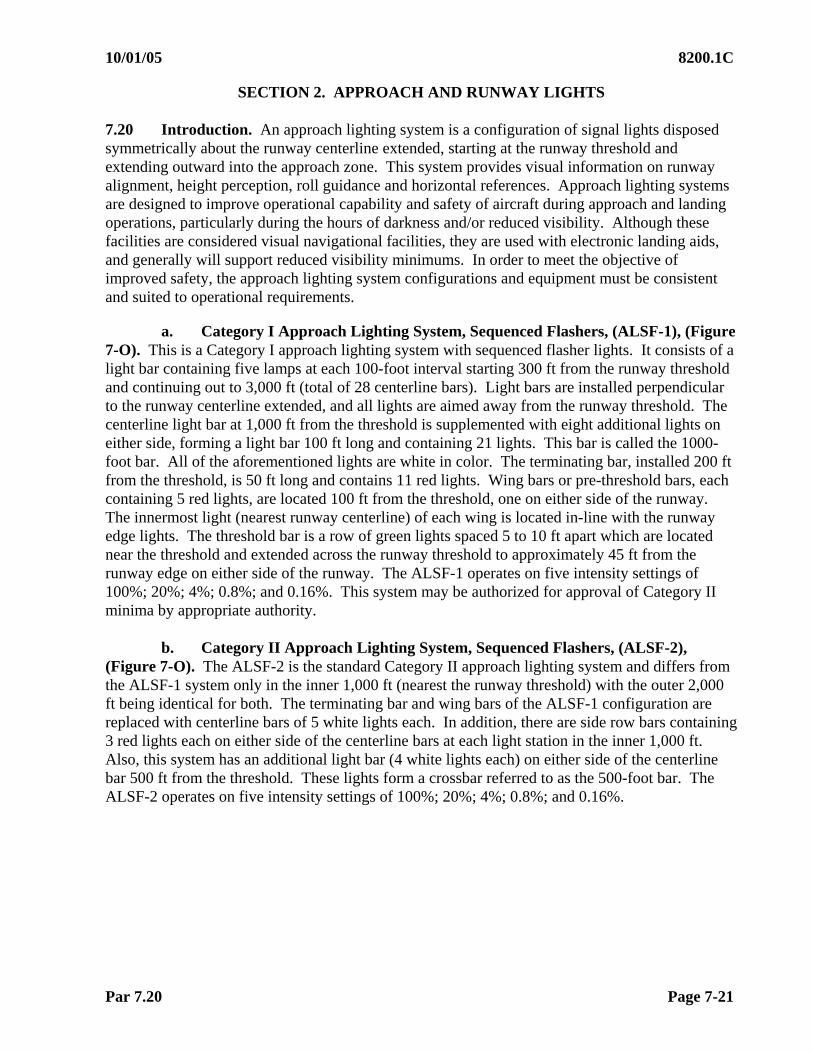
10/01/05 8200.1C
Par 7.20 Page 7-21
SECTION 2. APPROACH AND RUNWAY LIGHTS 7.20 Introduction. An approach lighting system is a configuration of signal lights disposed symmetrically about the runway centerline extended, starting at the runway threshold and extending outward into the approach zone. This system provides visual information on runway alignment, height perception, roll guidance and horizontal references. Approach lighting systems are designed to improve operational capability and safety of aircraft during approach and landing operations, particularly during the hours of darkness and/or reduced visibility. Although these facilities are considered visual navigational facilities, they are used with electronic landing aids, and generally will support reduced visibility minimums. In order to meet the objective of improved safety, the approach lighting system configurations and equipment must be consistent and suited to operational requirements.
a. Category I Approach Lighting System, Sequenced Flashers, (ALSF-1), (Figure
7-O). This is a Category I approach lighting system with sequenced flasher lights. It consists of a light bar containing five lamps at each 100-foot interval starting 300 ft from the runway threshold and continuing out to 3,000 ft (total of 28 centerline bars). Light bars are installed perpendicular to the runway centerline extended, and all lights are aimed away from the runway threshold. The centerline light bar at 1,000 ft from the threshold is supplemented with eight additional lights on either side, forming a light bar 100 ft long and containing 21 lights. This bar is called the 1000-foot bar. All of the aforementioned lights are white in color. The terminating bar, installed 200 ft from the threshold, is 50 ft long and contains 11 red lights. Wing bars or pre-threshold bars, each containing 5 red lights, are located 100 ft from the threshold, one on either side of the runway. The innermost light (nearest runway centerline) of each wing is located in-line with the runway edge lights. The threshold bar is a row of green lights spaced 5 to 10 ft apart which are located near the threshold and extended across the runway threshold to approximately 45 ft from the runway edge on either side of the runway. The ALSF-1 operates on five intensity settings of 100%; 20%; 4%; 0.8%; and 0.16%. This system may be authorized for approval of Category II minima by appropriate authority.
b. Category II Approach Lighting System, Sequenced Flashers, (ALSF-2), (Figure 7-O). The ALSF-2 is the standard Category II approach lighting system and differs from the ALSF-1 system only in the inner 1,000 ft (nearest the runway threshold) with the outer 2,000 ft being identical for both. The terminating bar and wing bars of the ALSF-1 configuration are replaced with centerline bars of 5 white lights each. In addition, there are side row bars containing 3 red lights each on either side of the centerline bars at each light station in the inner 1,000 ft. Also, this system has an additional light bar (4 white lights each) on either side of the centerline bar 500 ft from the threshold. These lights form a crossbar referred to as the 500-foot bar. The ALSF-2 operates on five intensity settings of 100%; 20%; 4%; 0.8%; and 0.16%.

8200.1C 10/01/05
Page 7-22 Par 7.20c
c. Sequenced Flashers for ALSF-1 and ALSF-2. In addition to the steady burning lights, both configurations are augmented with a system of sequenced flashing lights. One such light is installed at each centerline bar starting 1,000 ft from the threshold, out to the end of the system 3,000 ft from the threshold. Sequenced flasher lights on U.S. Air Force installations will commence 200 ft from the runway threshold. These lights sequence toward the threshold at a rate of twice per second. They appear as a ball of light traveling in the direction of the landing runway threshold at a very rapid speed.
d. Simplified Short Approach Lighting System (SSALS), (Figure 7-P). This is a 1,400-foot system, uses the standard ALS centerline light bar hardware, and is capable of being upgraded to a standard 3,000-ft system. It consists of seven light bars of five white lamps each, spaced 200 ft apart, beginning 200 ft from the threshold. Two additional light bars, containing five white lamps each, are located on either side of the centerline bar at 1,000 ft from the runway threshold, forming a crossbar 70 ft long. All lights in this system operate on three intensity settings of approximately 100%; 20%; and 4%.
e. Simplified Short Approach Lighting System with Sequenced Flashers (SSALF), (Figure 7-P). This system is identical to the SSALS system, except for the addition of three sequenced flashers located on the runway centerline at the outer three light bar stations. These flashers assist pilots in making early identification of the system in areas of extensive ambient background light. The sequenced flashers have an "on-off" switch and will operate on all intensity settings of the steady burning lights.
f. Simplified Short Approach Light System with Runway Alignment Indicator Lights (SSALR), (Figure 7-P). This is a 3,000-foot system and is identical to the SSALS except that five sequenced flasher lights spaced 200 ft apart are added on the centerline, beginning 200 ft beyond the end of the SSALS system. The sequenced flashers have a separate on-off switch but do not have a separate intensity control; they operate with all intensity settings of the steady burning lights and runway edge lights. SSALR(s) may be incorporated as part of an ALSF-2 system for operational purposes. During IFR conditions, the full ALSF-2 system must be operating.
NOTE: Some part-time control towers will leave just the SSALR(s) operational since Category II operations and subsequent use of ALSF-2 lights require a manned control tower.
g. Medium Intensity Approach Lighting System (MALS), (Figure 7-P). This
system is 1,400 ft in length, consisting of seven light bars of five lamps each, located on the runway centerline, extended and spaced 200 ft apart. Two additional light bars are located on either side of the centerline bar at 1,000 ft from the runway threshold. All lights in this system operate on two intensity settings, 100% and 10%, controlled through the runway edge lighting system.
h. Medium Intensity Approach Lighting System with Sequenced Flashers (MALSF), (Figure 7-P). This system is identical to the MALS, except that three sequenced flasher lights are located at the outer three light bar stations. These sequenced flashers do not have an intensity control; they operate on both intensity settings of the steady burning lights.

02/01/07 8200.1C CHG 1
Par 7.20i Page 7-23
i. Medium Intensity Approach Lighting System with Runway Alignment Indicator Lights (MALSR), (Figure 7-P). This system is the same as a MALS configuration, except that five sequenced flashers are added on the extended runway centerline, beginning 200 ft beyond the outer end of the MALS system and extending out at 200-foot intervals to 3,000 ft. The MALSR and SSALR may have an overall length of 2,400 ft at locations where the glide slope is greater than 2.75. The MALSR may be used with precision navigation aids, i.e., PAR, ILS.
j. Omnidirectional Approach Lighting System (ODALS) consists of seven omnidirectional flashing lights. Five lights are located on the runway centerline extended, with the first light located 300 ft from the threshold and extending at equal intervals up to 1,500 ft from the threshold. The other two lights are located, one on each side of the runway threshold. They must flash in sequence toward the runway threshold at a rate of once per second, with the two lights located on each side of the runway flashing simultaneously.
k. Runway End Identifier Lights (REIL). REIL provide rapid and positive identification of the approach end of a particular runway. REIL do not provide course alignment, descent, or altitude information. The system consists of a pair of synchronized flashing lights located laterally on each side of the runway threshold. REIL systems may be either omni-directional or unidirectional facing the approach area.
(1) Unidirectional REIL (Figure 7-P). Unidirectional REIL are installed where environmental conditions require that the area affected by the flash from the REIL will be greatly limited. Unidirectional REIL systems have a flash rate of 120 flashes per minute ( 10%), and a beam pattern of 10 vertical and 30 horizontal. Installation instructions call for the beam axis of an unbaffled unit to be aligned 15 outward from a line parallel to the runway and inclined at an angle 10 above the horizontal. If this standard setting is operationally objectionable, optical baffles are provided and the beam axis of the unit is oriented 10 outward from a line parallel to the runway centerline and inclined at an angle of 3above horizontal.
(2) The Omni-directional REIL, (OD REIL) system provides good circling guidance and is the preferred system. OD REIL systems have a flash rate of 60 flashes per minute ( 10%), and a beam pattern from 2 to 10 above horizontal.
l. Sequence Flashing Lights (SFL)/ Runway Alignment Indicator Lights (RAIL) are the same kind of lights but are used differently with various approach lighting systems and affect visibility minimums. SFL(s) are used with precision approaches and ALSF-1/ 2 systems. Inoperative SFL(s) have no affect on Category I or III service, but deny Category II service. Runway alignment indicator lights are part of SSAL and MALS systems when used for precision approaches. Inoperative RAIL(s) result in raised Category I minimums, deny Category II service, and have no affect on Category III service.
8200.1C 9/14/09 Chg 2
Page 7-24 Par 7.21
7.21 Pre-Flight Requirements
a. Facilities Maintenance. In addition to preparations contained in Chapter 4, Section 3, Facilities Maintenance personnel should ensure that all light units are operating, aimed at the proper angle, and in a clean condition.
b. Air. The flight inspector should consult with appropriate personnel to determine local operational procedures and the correct transmitter keying sequence for Radio Controlled Lights. Also see Chapter 4, Section 3. 7.22 Flight Inspection Procedures. These lighting system configurations are identified as the United States Standard. While there are other approach lighting system configurations in existence, no attempt has been made to describe all systems in this chapter due to the fact that they are considered as non-standard lighting systems and will not be found in quantity. Where it is necessary to make an in-flight evaluation of non-standard systems, the flight inspector must determine that they fulfill the operational requirements for which they are installed and do not create signals which might be misleading or hazardous. For airports with no prior IFR service or airports that have constructed a new IFR runway, a night flight inspection must be conducted to determine the adequacy of the light systems to support the procedure. Night IFR operations must not be allowed until the night evaluation is complete. A subsequent night evaluation may be required when lighting systems have been modified, replaced, or reconfigured, depending on the type of lighting and the extent of the modifications. Approach lights, except semi-flush lights, are aimed vertically to a point on the ILS or PAR glide path 1,600 ft in advance of the light; therefore, it is necessary that the aircraft be positioned on the glide path for proper evaluation. For non-precision type navigational facilities, a 3 glide path angle is simulated for aiming purposes.
a. Checklist. The following checks will be performed on flight inspections of approach lighting systems and runway end identifier lights.
(1) Light Intensity
(2) Lamp Alignment
(3) Inoperative Lights
(4) Radio Controlled Lights
b. Detailed Procedures. A commissioning flight inspection is required for all airport lighting systems, including approach lights, REILS, runway lights, and radio control of lights, that support a public-use or military instrument approach procedure. Recurring inspections will be conducted concurrently with the periodic inspection of the primary navigational facility which the lighting system supports. The periodic inspection of the primary navigational facility will be considered complete if circumstances prohibit inspection of the lighting system, provided all other checklist items have been accomplished satisfactorily.
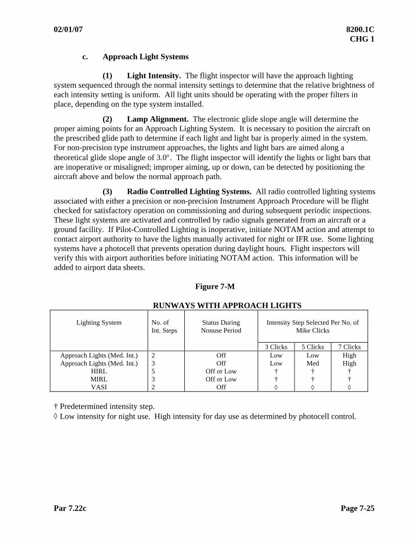
02/01/07 8200.1C CHG 1
Par 7.22c Page 7-25
c. Approach Light Systems
(1) Light Intensity. The flight inspector will have the approach lighting system sequenced through the normal intensity settings to determine that the relative brightness of each intensity setting is uniform. All light units should be operating with the proper filters in place, depending on the type system installed.
(2) Lamp Alignment. The electronic glide slope angle will determine the proper aiming points for an Approach Lighting System. It is necessary to position the aircraft on the prescribed glide path to determine if each light and light bar is properly aimed in the system. For non-precision type instrument approaches, the lights and light bars are aimed along a theoretical glide slope angle of 3.0. The flight inspector will identify the lights or light bars that are inoperative or misaligned; improper aiming, up or down, can be detected by positioning the aircraft above and below the normal approach path.
(3) Radio Controlled Lighting Systems. All radio controlled lighting systems associated with either a precision or non-precision Instrument Approach Procedure will be flight checked for satisfactory operation on commissioning and during subsequent periodic inspections. These light systems are activated and controlled by radio signals generated from an aircraft or a ground facility. If Pilot-Controlled Lighting is inoperative, initiate NOTAM action and attempt to contact airport authority to have the lights manually activated for night or IFR use. Some lighting systems have a photocell that prevents operation during daylight hours. Flight inspectors will verify this with airport authorities before initiating NOTAM action. This information will be added to airport data sheets.
Figure 7-M
RUNWAYS WITH APPROACH LIGHTS
Lighting System No. of Status During Intensity Step Selected Per No. of Int. Steps Nonuse Period Mike Clicks 3 Clicks 5 Clicks 7 Clicks
Approach Lights (Med. Int.) 2 Off Low Low High Approach Lights (Med. Int.) 3 Off Low Med High
HIRL 5 Off or Low † † † MIRL 3 Off or Low † † † VASI 2 Off
† Predetermined intensity step. Low intensity for night use. High intensity for day use as determined by photocell control.
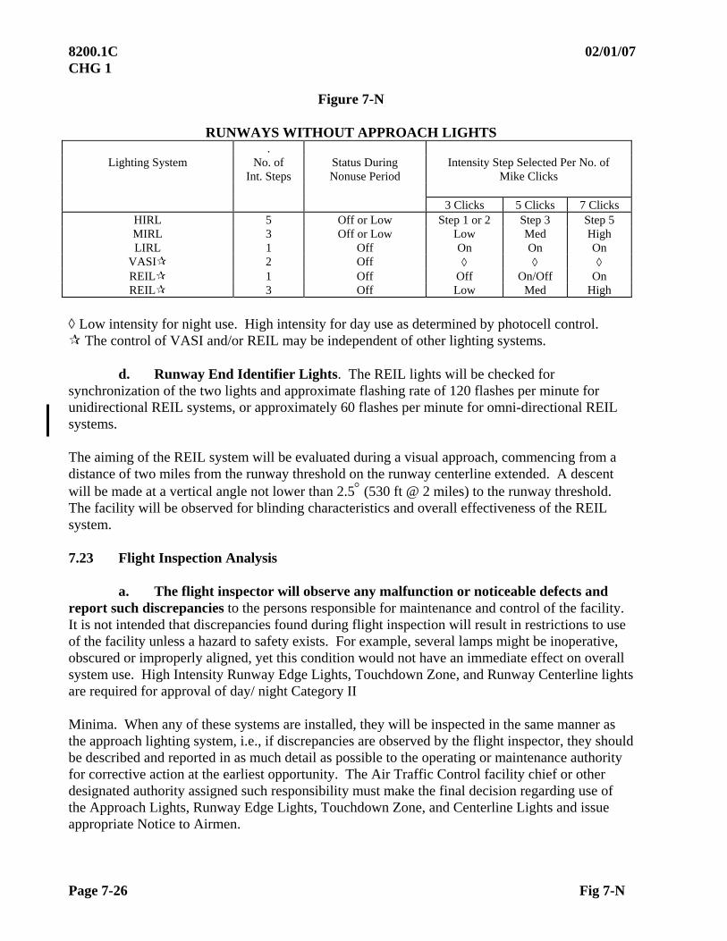
8200.1C 02/01/07 CHG 1
Page 7-26 Fig 7-N
Figure 7-N
RUNWAYS WITHOUT APPROACH LIGHTS .
Lighting System No. of Status During Intensity Step Selected Per No. of Int. Steps Nonuse Period Mike Clicks 3 Clicks 5 Clicks 7 Clicks
HIRL 5 Off or Low Step 1 or 2 Step 3 Step 5 MIRL 3 Off or Low Low Med High LIRL 1 Off On On On
VASI 2 Off REIL 1 Off Off On/Off On REIL 3 Off Low Med High
Low intensity for night use. High intensity for day use as determined by photocell control. The control of VASI and/or REIL may be independent of other lighting systems.
d. Runway End Identifier Lights. The REIL lights will be checked for synchronization of the two lights and approximate flashing rate of 120 flashes per minute for unidirectional REIL systems, or approximately 60 flashes per minute for omni-directional REIL systems. The aiming of the REIL system will be evaluated during a visual approach, commencing from a distance of two miles from the runway threshold on the runway centerline extended. A descent will be made at a vertical angle not lower than 2.5 (530 ft @ 2 miles) to the runway threshold. The facility will be observed for blinding characteristics and overall effectiveness of the REIL system. 7.23 Flight Inspection Analysis
a. The flight inspector will observe any malfunction or noticeable defects and report such discrepancies to the persons responsible for maintenance and control of the facility. It is not intended that discrepancies found during flight inspection will result in restrictions to use of the facility unless a hazard to safety exists. For example, several lamps might be inoperative, obscured or improperly aligned, yet this condition would not have an immediate effect on overall system use. High Intensity Runway Edge Lights, Touchdown Zone, and Runway Centerline lights are required for approval of day/ night Category II
Minima. When any of these systems are installed, they will be inspected in the same manner as the approach lighting system, i.e., if discrepancies are observed by the flight inspector, they should be described and reported in as much detail as possible to the operating or maintenance authority for corrective action at the earliest opportunity. The Air Traffic Control facility chief or other designated authority assigned such responsibility must make the final decision regarding use of the Approach Lights, Runway Edge Lights, Touchdown Zone, and Centerline Lights and issue appropriate Notice to Airmen.
02/01/07 8200.1C CHG 1
Par 7.24 Page 7-27
7.24 Tolerances
a. Approach Lighting Systems, Runway Edge Lights, Touchdown Zone, and Runway Centerline Lights will meet the following tolerances. It is not intended that these facilities be classified in accordance with Chapter 5, Section 1 unless a hazard to safety exists.
(1) Light Intensity. The system must be capable of operating on all light
intensity settings; the relative intensity of all lights must be uniform on each individual setting. Light intensity should be checked by pilot control function and controller operation.
(2) Lamp Alignment. All lamps must be aimed in both vertical and horizontal axes to provide the proper guidance along an electronic glide path of approximately 3.0.
(3) Inoperative Lights. For a commissioning inspection, all lights of each system must be operative, and proper filters must be in place. During routine inspection if inoperative, obscured, or misaligned lights are detected, the number and location must be noted in as much detail as practicable and this information reported to the operating or maintenance authority for corrective action.
(4) Touchdown Zone and Centerline Lighting Systems. These systems are integral parts of the Category II ILS and will conform to specified criteria. When reduced minimums have been authorized on the basis of these systems being available and operative, compliance with the below criteria is required for the application of reduced minimums. Whenever the system fails to meet the following requirements, out-of-tolerance conditions exist and the system automatically reverts to application of Category I minima.
(a) No more than 10% of the lights of the Centerline Lighting System may be inoperative.
(b) No more than 10% of the lights on either side of the Touchdown Zone Lighting System may be inoperative.
(c) No more than four consecutive lights of the Centerline Lighting system may be inoperative.
(d) More than one bar (three-light fixture) of the touchdown zone system may be inoperative; however, two adjacent bars on the same side of the system may not be inoperative. A bar is considered inoperative when all of its lights are out.
8200.1C 02/01/07 CHG 1
Page 7-28 Par 7.24b
b. Runway End Identifier Lights (REIL) will meet the following tolerances. It is not intended that the facility be classified in accordance with Chapter 5, Section 1 unless a hazard to safety exists.
(1) Light Intensity. The lights must be oriented so that the light intensity is substantially uniform on the runway centerline extended. The character of appearance of the light must be aviation white or xenon ARC. No color is permitted, and both lights must be operative. The flashing rate can be measured best by observation from the ground; however, the flight inspector should observe this feature for grossly rapid or slow flashing rate.
(2) Lamp Alignment. The system must be aligned or shielded so as to be unobjectionable to a pilot on final approach within 1,500 ft of the runway threshold on an approach path of 2.5o or higher. If the REIL lights produce an unacceptable glare within 1,500 ft of the runway threshold, the flight inspector must request that the aiming of the lamps be adjusted.
7.25 Adjustments. Maintenance personnel should make every effort to correct any discrepancies discovered on an approach lighting system or a REIL system during the conduct of the flight inspection of the primary navigational facility. Where a hazard to safety exists, correction of discrepancies will be made prior to further use of the system; otherwise, correction of minor deficiencies will be made as soon as possible (Ref: Paragraphs 7.23 and 4.23e).

02/01/07 8200.1C CHG 1
Fig 7-O Page 7-29
Figure 7-O LIGHTING SYSTEM CONFIGURATIONS
ALSF-2 ALSF-1
Flashing Light Steady Burning Light Red Light Green Light
1000 ft
2400 ft/3000 ft
500 ft
1000 ft
100 ft spacing
2400/3000 ft
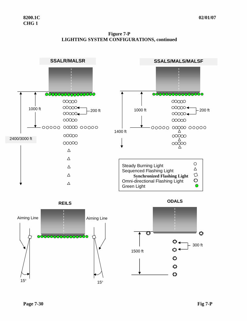
8200.1C 02/01/07 CHG 1
Page 7-30 Fig 7-P
Figure 7-P LIGHTING SYSTEM CONFIGURATIONS, continued
SSALS/MALS/MALSF
1400 ft
1000 ft 200 ft
SSALR/MALSR
1000 ft 200 ft
Aiming Line Aiming Line
15 15
REILS
Steady Burning Light Sequenced Flashing Light
Synchronized Flashing Light Omni-directional Flashing Light Green Light
ODALS
1500 ft
300 ft
2400/3000 ft

10/01/05 8200.1C
Page 8-i
CHAPTER 8. COMMUNICATIONS
TABLE OF CONTENTS
Paragraphs Title Pages
SECTION 1. ULTRA-HIGH FREQUENCY (UHF)/ VERY HIGH FREQUENCY (VHF)
8.10 INTRODUCTION....................................................................................................8-1 8.11 PREFLIGHT REQUIREMENTS ............................................................................8-1 8.12 FLIGHT INSPECTION PROCEDURES ................................................................8-1
a. Checklist......................................................................................................8-1 b. Detailed Procedures ....................................................................................8-2 c. Coverage .....................................................................................................8-2 d. Terminal Communications (TCOM)...........................................................8-2 e. En route Communications (ECOM)............................................................8-2 f. Automatic Terminal Information Service (ATIS).......................................8-2 g. Automated Weather Observing System (AWOS)/
Automated Surface Aviation Observing System (ASOS)...........................8-2 h. Transcribed Weather Broadcast (TWEB) ...................................................8-3
8.13 ANALYSIS ..............................................................................................................8-3 8.14 TOLERANCES........................................................................................................8-3 8.15 ADJUSTMENTS...........................................................................................8-4

8200.1C 10/01/05
Page 8-ii
Paragraphs Title Pages
SECTION 2. DIRECTION FINDING STATIONS (DF) 8.20 INTRODUCTION .........................................................................................8-4 8.21 PREFLIGHT REQUIREMENTS..................................................................8-5
a. Facilities Maintenance Personnel ......................................................8-5 b. Flight Personnel .................................................................................8-5
8.22 FLIGHT INSPECTION PROCEDURES......................................................8-6 a. Checklist ............................................................................................8-6 b. Detailed Procedures ...........................................................................8-6
(1) Preliminary Station Alignment ..............................................8-6 (2) Bearing Accuracy ..................................................................8-7 (3) AFIS Alignment and Orbit ....................................................8-7 (4) Theodolite Orbit.....................................................................8-7 (5) Checkpoint Orbit ...................................................................8-8 (6) Analysis of Bearing Accuracy ...............................................8-8 (7) Periodic Inspections...............................................................8-8 (8) Commissioning Inspection ....................................................8-9 (9) Communications and Coverage.............................................8-9
(10) Station Passage ......................................................................8-9 (11) Operator Performance............................................................8-9 (12) Standby Power .......................................................................8-10 (13) DF Approaches ......................................................................8-10
8.23 STANDBY EQUIPMENT ............................................................................8-10 8.24 TOLERANCES .............................................................................................8-10 8.25 ADJUSTMENTS...........................................................................................8-11

10/01/05 8200.1C
Par 8.10 Page 8-1
CHAPTER 8. COMMUNICATIONS
SECTION 1. ULTRA-HIGH FREQUENCY (UHF)/ VERY HIGH FREQUENCY (VHF)
8.10 INTRODUCTION. Air/ ground communications services within the NAS are classified according to function. En route communications (ECOM) is the service provided between ARTCC controllers and pilots, and includes Remote Center Air/ Ground (RCAG) Communications and Backup Emergency Communications (BUEC) facilities. Terminal communications (TCOM) is the service provided between approach and departure controllers and pilots in terminal airspace, including RCF and ATCT facilities. FSS communications (FCOM) is the service provided between the FSS and the pilot and is advisory in nature, such as EFAS. Other advisory services include ATIS, AWOS, and ASOS, all of which may be transmitted on a NAVAID or a discrete communications frequency. 8.11 PREFLIGHT REQUIREMENTS. The flight inspector must prepare for the flight inspection in accordance with the procedures outlined in Chapter 4, Section 3. Local Facilities Maintenance and Air Traffic personnel must provide coverage requirements, including tailored sector definitions. 8.12 FLIGHT INSPECTION PROCEDURES. The performance of communications facilities is accurately predicted by computer-aided modeling. Therefore, commissioning inspections are only required when requested by Facilities Maintenance Engineering. Periodic inspections must be conducted on a surveillance basis in conjunction with evaluation of associated navigation and air traffic control facilities.
a. Checklist
Type Check Reference Paragraph
C P
TCOM 8.12c 1 2 ECOM 8.12d 1 2 ATIS 8.12e 1, 3 2, 3 AWOS/ ASOS 8.12f 1, 3 2, 3 TWEB 8.12g 1, 3 2, 3
FOOTNOTES:
1. When requested.
2. Surveillance inspections conducted during other inspection evaluations.
3. If the NAVAID has no other voice services, verify that the voice broadcast effect on the navigation signal is within applicable tolerances.

8200.1C 10/01/05
Page 8-2 Par 8.12
b. Detailed Procedures
(1) Coverage. When coverage cannot be predicted by facility engineering, a flight inspection will be requested. Evaluate facilities where the minimum en route altitude (MEA) is determined by communications coverage.
(2) During requested commissioning inspections, coverage must be determined by the air traffic service requirements established locally.
(3) Flight profiles may vary according to the local requirements and could include an orbit or a detailed sector evaluation. Communications for fixes, hand-off positions, changeover points, or controlled airspace must be checked.
(4) Additional frequencies assigned to the same service requirement will not
require a complete inspection, but should be evaluated on a surveillance basis.
(5) Light Gun Signals must be checked for adequate coverage on the ground and in flight.
(6) Standby equipment must be checked during any requested commissioning inspection.
c. Terminal Communications (TCOM) includes tower, ground control, clearance delivery, departure, arrival, and light gun communications. Commissioning inspections, when requested, must be conducted at the extremities of the airport to determine if there are blind spots and adequate coverage. Departure and arrival frequencies must be checked to verify service throughout the established sector volume.
d. En route Communications (ECOM) includes VHF and UHF air/ ground frequencies and BUEC channels. When requested, these frequencies must be evaluated throughout the established sector service volume.
e. Automatic Terminal Information Service (ATIS) broadcast on a NAVAID facility must be commissioned and reported with that NAVAID (see Chapter 11, Section 1). When commissioning is requested, ATIS broadcast on a discrete communications frequency must be checked in accordance with local requirements. Departure ATIS must be verified at the airport extremities.
f. Automated Weather Observing System (AWOS)/Automated Surface Aviation Observing System (ASOS). These systems provide local weather observations and may be broadcast on a NAVAID or a discrete VHF communications frequency. Transmission on a NAVAID must be verified in accordance with Chapter 11 or 12. Local altimeter settings from these systems can result in lower minimums for standard instrument approach procedures. Whenever this occurs, ensure that the associated procedure has been flight inspected to the new minimum prior to publication. When AWOS/ ASOS is used as the primary airport altimeter source, flight inspection must verify reception at or before the initial approach fix (IAF).

10/01/05 8200.1C
Par 8.12 Page 8-3
g. Transcribed Weather Broadcast (TWEB). This system broadcasts route-oriented data with specially prepared National Weather Service forecasts, inflight advisories, and winds aloft plus pre-selected current information, such as routine or special weather reports (METAR/ SPECI), NOTAM(s), and special notices. The data is broadcast continuously over selected L/ MF and H NDB(s) and/or VOR(s). 8.13 ANALYSIS. Unsatisfactory conditions must be brought to the attention of the appropriate air traffic control and facilities maintenance personnel. 8.14 TOLERANCES
a. Maximum Recommended Coverage. Communications frequencies are engineered for distinct volumes of airspace, which are guaranteed to be free from a preset level of interference from an undesired source. Each specific function has its own frequency protected service volume. Some are cylinders, and others are odd multi-point geometric shapes. These odd shapes are normally required for en route ATC services. Following is a table of maximum altitude and radius dimensions recommended for each type of service. Under no circumstances will a service volume be approved at an altitude and distance greater than the radio line of sight (RLOS) distance (reference Figure A3-1).
Maximum Dimensions
Service Altitude Distance ECOM Low Altitude Surface to 23,000 60 Intermediate Altitude 11,000 to 25,000 60 High Altitude 24,000 to 35,000 150 Ultra-High Altitude 35,000 and above 150 TCOM Ground Control 100 5 Clearance Delivery 100 5 PAR (Military) 5,000 15 Helicopter 5,000 30 Local Control 25,000 30 Approach Control 25,000 60 Departure Control 25,000 60 ATIS Arrival 25,000 60 Departure 100 5 AWOS/ ASOS 10,000 25 NAVAID Chapter 11 or 12 Discrete Comm At or before the IAF TWEB Chapter 11 or 12
8200.1C 10/01/05
Page 8-4 Par 8.14
b. Local Requirements. Communications service volume requirements are established by the controlling Air Traffic facility based on local operational requirements. When a flight inspection is requested, these local requirements must be validated and adjusted, if necessary, for satisfactory operation. Communications must be clear and readable.
c. Restrictions. USAF air traffic control facilities will not be restricted due to
unusable radios unless the ability to provide required service is severely limited; the loss of 50% or more of published frequencies or loss of VHF/ UHF emergency capability is considered a severe limitation. Document inoperative or unusable radios and frequencies on the flight inspection report. The inoperative or unusable radio or frequency can be returned to service after a satisfactory operational check is conducted by local aircraft at a distance of maximum intended use and altitude of MVA/ MEA.
d. Light Gun Requirements
(1) Ground. Ensure adequate coverage for operational control of ground
traffic.
(2) Air. Three miles in all quadrants at the lowest traffic pattern altitude.
8.15 ADJUSTMENTS. All requests for facility adjustments must be specific. Flight inspection certification must be based on facility performance.
SECTION 2. DIRECTION FINDING STATIONS (DF) 8.20 INTRODUCTION. Direction finding stations use normal VHF or UHF communication transmissions from aircraft to determine bearing information from a ground station. Flight Service Station (FSS) personnel may then relay this information to an aircraft in flight to assist in determining the aircraft position. Doppler type VHF/ DF is the standard equipment within the FAA. Older equipment, such as U.S. Navy VHF and UHF/ DF facilities, may still be in use at certain locations. Operational performance and flight inspection procedures are the same for all DF equipment, with minor tolerance differences as noted in Paragraph 8.24. AFIS is the accuracy standard, but non-AFIS equipped aircraft with suitable communication equipment may perform DF inspections when operated in accordance with appropriate chapters in this manual. Direction Finding stations are normally located at or near airports and/or Flight Service Stations. Many DF facilities have the capability of providing an emergency instrument approach procedure where favorably sited with respect to an airport. Assuring the accuracy of these procedures is an integral part of the DF flight inspection.

10/01/05 8200.1C
Par 8.21 Page 8-5
8.21 PREFLIGHT REQUIREMENTS
a. Facilities Maintenance personnel must prepare for flight inspection in accordance with procedures specified in Chapter 4, Section 3. For commissioning inspections, Facilities Maintenance personnel should:
(1) Prepare a detailed outline of any special information or procedure(s) desired as an outcome of the flight inspection;
(2) Prepare the desired sequence for the inspection;
(3) Optimize the facilities equipment.
(4) Ascertain that fully qualified operators and maintenance technicians are available.
b. Flight Personnel must prepare for the DF flight inspection in accordance with procedures specified in Chapter 4, Section 3. Aircrews must:
(1) For commissioning inspections, prepare a chart with the DF facility accurately plotted and appropriate radials and a 360o orbit drawn. The scale of the chart should be 1:500,000 (Sectional) or larger, and the areas to be overflown evaluated per Chapter 6.
(2) Obtain information from Facilities Maintenance personnel pertinent to the planned inspection, including desired outcomes, expected performance, and sequence of events.
(3) For periodic inspections, obtain previous flight inspection data pertinent to
the planned inspection.

8200.1C 10/01/05
Page 8-6 Par 8.22
8.22 FLIGHT INSPECTION PROCEDURES. The aircraft must be positioned precisely to determine bearing accuracy and service area. AFIS has the positioning capability to the accuracy standard required. Non-AFIS aircraft may perform the inspection if accurately plotted ground checkpoints are selected and the aircraft can be safely maneuvered over these checkpoints. Where neither AFIS nor ground checkpoint positioning is available, the theodolite must be used. The DF operator will be briefed to compute all bearings as from the DF facility, except for station passage and approach procedures.
a. Checklist. All of the checks listed below must be performed on the commissioning flight inspection. Special flight inspections may require any one or all of these checks, depending on the reason for the inspection. Periodic inspection of bearing accuracy will be conducted in conformance with this section.
Type of Check Reference
Paragraph C P
Preliminary Station Alignment 8.22 X Bearing Accuracy 8.22 X X Alignment Orbit 8.22 X Communication and Coverage 8.22 X X Station Passage 8.22 X Operator Performance 8.22 X Standby Power 8.22 X DF Approaches 8.22 X
b. Detailed Procedures
(1) Preliminary Station Alignment
(a) Use AFIS and select an azimuth from the DF facility to establish an alignment reference. For non-AFIS aircraft, use the theodolite on a pre-determined azimuth or select a checkpoint which lies within the quadrant of the planned orbit containing the maximum number of checkpoints. At an altitude which will assure radio line of sight, obtain a DF bearing from the operator and compare this bearing with the actual bearing determined from AFIS, theodolite, or checkpoint.
(b) If the DF bearing error is less than +6o, continue an orbital flight for
at least 90o of azimuth. Non-AFIS aircraft will orbit in the direction of the maximum number of checkpoints; theodolite or AFIS orbit direction is at the discretion of the flight inspector and/or DF
operator. If the remaining bearings in this primary quadrant are within +6o, proceed with the bearing accuracy check as required in Paragraph 8.22(b)(2). If the reference or succeeding DF
bearings in this primary quadrant exceed +6o error, the equipment must be adjusted and the procedure repeated. From the preliminary check, data should be derived to balance the overall error curve.

10/01/05 8200.1C
Par 8.22 Page 8-7
(2) Bearing Accuracy
(a) DF coverage will not substantially exceed line-of-sight. Coverage is dependent on power output, antenna height, terrain, and the effects of signal reflection. The bearing accuracy check is conducted to determine the ability of the DF facility to furnish accurate bearings throughout the service area during commissioning, and forms the reference for other inspections. This is accomplished by comparing DF bearings from the facility with bearings measured from AFIS, theodolite, or ground checkpoints.
(b) If communications become unsatisfactory, or if bearing errors exceed tolerance, climb above the altitude being flown until adequate communications are established again and/or bearing errors are satisfactory.
(c) If communications and bearing accuracy remain satisfactory on the
next measurement, descend to the appropriate selected altitude or to the minimum altitude which will provide satisfactory bearings and communications, whichever is higher, and continue to the next checkpoint. This procedure will provide the lowest altitudes throughout the coverage area of the DF facility at which acceptable bearing information and communication can be expected.
(3) AFIS Alignment and Orbit
(a) Proceed to the range appropriate to the facility and to the altitude
previously determined. If HYBRID Mode is not available, use the minimum DME update altitude and plan to fly a second orbit for coverage if the minimum DME update altitude is higher than the intended use altitude. The AFIS will be programmed for the DF facility parameters (Identification, Latitude, Longitude, Magnetic Variation) inserted in the FI FAC series.
(b) For initial facility alignment (reference), the AFIS system will be
programmed for an RNAV Radial flight path, Inbound or Outbound, beyond 10 nm from the DF antenna. DF bearing accuracy may be determined by comparing the operator DF bearing to the bearing displayed on the CDU. RNAV/ Autopilot coupled flight is recommended for radial or orbit maneuvers.
(c) After the initial alignment has been accomplished, an orbit CW or CCW will be programmed and flown. An event mark will be made on the recording at the position the transmitter is keyed for the DF steer; comparison can then be made to the 5o bearing marks on the analog recording.
(4) Theodolite Orbit
(a) The theodolite must be aligned to read magnetic bearings from the
DF station. It should be located adjacent to the DF site at a position where the aircraft will be visible throughout as much of the orbit as possible. This position should be less than 300 ft from the site. The flight inspector should brief the DF operator and the theodolite operator to avoid confusion during the actual flight inspection.
8200.1C 10/01/05
Page 8-8 Par 8.22
(b) The theodolite operator must track the aircraft throughout the orbit and actuate one event mark (1020 Hz tone) at each 10 of azimuth. The pilot must transmit for a DF bearing at frequent intervals and actuate the pilot event mark on the opposite side of the recording during each such transmission. The airborne technician must label each of these event marks. The leading edge of the theodolite event mark will represent the actual bearing of the aircraft from the station, and the pilot event marks will represent the DF bearing. The airborne technician will label the DF bearing as reported by the DF operator and determine the error with the use of proportional (“Ten Point”) dividers.
(5) Checkpoint Orbit
(a) Position the aircraft over the predetermined checkpoints. Where
possible, these checkpoints should be located at or near the limits of the DF and communication range capability to validate bearing accuracy and service area simultaneously. As the aircraft approaches the first ground checkpoint or measured bearing, the pilot must transmit a 10-second radio signal, timed so that the aircraft will be over the checkpoint in the middle of the transmission. Compare the bearing provided by the DF operator with the measured magnetic bearing. Note each DF bearing, magnetic bearing, error, radio frequency, altitude, and distance on he flight inspection report. Bearing errors must be computed in the same manner as VOR course alignment errors; i.e., when the aircraft bearing is less than the bearing reported by the DF operator, the error is negative.
(b) Proceed with the orbit of the facility at the appropriate range and
altitudes, obtaining bearings as often as practical. After initial contact has been established, a 5 to 10 second radio signal is usually sufficient to obtain bearings. Because of the capability of almost instantaneous readout on the Doppler type DF, a five-second radio signal is usually sufficient to obtain bearings on this type facility.
(6) Analysis of Bearing Accuracy. After completing the bearing accuracy
check, station adjustment may be necessary to balance station error and keep all bearings within tolerance. Whenever orbital bearing errors are beyond 6 on any type of flight inspection, verify the errors radially. If, due to the availability of ground checkpoints, the exact azimuth found suspect in the orbit cannot be verified, radially fly another inbound/ outbound radial in the same 90 quadrant. When an out-of-tolerance condition cannot be corrected, the controller must be advised of the area(s) not to be used. The condition(s) will be noted on the flight inspection report and the facility assigned a "restricted" classification. A NOTAM will not be issued.
(7) Periodic Inspections will include a bearing accuracy check at a minimum distance of 20 nm and at a minimum altitude of 1500 ft, an altitude which will provide obstacle clearance in the area, or radio line of sight, whichever is highest. A minimum of one bearing check must be accomplished on each published frequency and, if available, the VHF emergency frequency.

10/01/05 8200.1C
Par 8.22 Page 8-9
(8) Commissioning Inspection
(a) An orbit procedure, as outlined in this section, must be used to evaluate bearing accuracy for the commissioning flight inspection. Orbit radius must be the minimum of:
1 40 miles for Doppler DF facilities;
2 30 miles for older equipment;
3 operational requirements The altitude must be 1,500 ft above site elevation, the minimum altitude providing 1,000 ft of obstacle clearance (2,000 ft obstacle clearance in designated mountainous areas), or the minimum altitude which will provide radio line-of-sight, whichever is the higher.
(b) AFIS or theodolite bearings may be taken at frequent intervals as close together as 10. A minimum of four bearings must be taken for each quadrant, regardless of which orbit method is used.
(9) Communications and Coverage. Voice communication is the means for getting DF information to a pilot. Quality of communications greatly affects the capability of the DF to provide quality service. Bearings must be obtained on as many of the published frequencies as practical during the checkpoint orbit. For a commissioning inspection, all frequencies proposed for use will be checked. This may be accomplished on the orbit or during radial flight at the extremes of coverage. For periodic inspections, voice communications will be checked on all frequencies if less than four are used for DF bearings. If more than four are available, at least four frequencies will be checked. The VHF emergency frequency, if available, must be evaluated during all flight inspections. Where coverage is required at greater distances for special purposes, it can be determined by either orbital or radial flight at the greater distance and altitude.
(10) Station Passage. Fly inbound to the DF antenna from a position at least 5
miles out and an altitude of 1,500 ft above the antenna. Obtain sufficient steers from the DF operator to overfly the antenna and note the distance from the aircraft to the DF antenna when the operator reports station passage. This check may be performed in conjunction with the DF approach procedure (Paragraph 8.22b(13) at the discretion of the pilot and DF operator.
8200.1C 10/01/05
Page 8-10 Par 8.22
(11) Operator Performance. The flight inspector must determine that the overall system is safe and reliable. The operator should be able to direct the aircraft over the facility, report station passage, and provide pertinent information relative to the use of DF service. If an emergency approach procedure has been established (DF approaches are not SIAP(s)), the operator should be able to direct the aircraft to a position from which a safe landing can be made.
(12) Standby Power
(a) Standby power, if installed, must be checked on the commissioning inspection to ensure that no derogation of communication or bearing accuracy occurs when using the alternate power source. An orbit on each source will be performed and the bearing accuracy and overall station error compared. If standby power is installed at a later date, the facility will be inspected on standby power at the first periodic inspection scheduled after the installation of the standby power system. Inspections after a change in the standby power source are at the discretion of the Airway Facilities Engineering Division.
(b) Periodic inspections normally will not require the use of standby
power systems. Airway Facilities personnel may request a check on standby power if they suspect that the alternate power source causes a deterioration in the performance of the DF facility.
(13) DF Approaches
(a) The emergency DF approach must be checked at the time of
commissioning. Airway Facilities personnel or DF facility operators may request a check of the approach during any inspection if, in their opinion, verification of the procedure, obstructions, or equipment performance is desired.
(b) Conduct the approach in accordance with the DF operator’s instructions and evaluate the obstacle clearance and flyability per Chapter 6. The flight inspector must note the position of the aircraft relative to the airport and determine whether it will permit a safe landing. 8.23 STANDBY EQUIPMENT. Where installed, standby equipment will meet the same operational tolerances during commissioning as the primary equipment. Periodic inspection of standby equipment is not required unless requested by Airway Facilities, Engineering, or the DF operator.

10/01/05 8200.1C
Par 8.24 Page 8-11 (and 12)
8.24 TOLERANCES. All DF stations must conform to these tolerances for an UNRESTRICTED classification. Classification of the facility is the responsibility of the flight inspector.
a. Bearing Accuracy
VHF/ DF, UHF/ DF: Each DF bearing must be within 10o of the actual bearing.
VHF/ DF (doppler): Each DF bearing must be within 6o of the actual bearing
b. Coverage
VHF/ DF UHF/ DF: 30 miles VHF/ DF (doppler): 40 miles
c. Communications. Communications on all required frequencies must be
clear and readable throughout the coverage area.
d. Station Passage. Station passage must be recognized within 1 1/2 miles at 1,500 ft AGL.
e. Controller Performance. Controllers must be capable of directing an aircraft to the station, reporting station passage, providing guidance for an emergency approach, and vectoring aircraft to avoid terrain and obstacles.
f. Standby Power. The DF facility will meet all tolerances in this chapter when operating on an alternate power source.
g. Emergency Approaches. Where a DF approach procedure is established, the system must provide the capability of directing the aircraft to a position from which a safe landing can be made. 8.25 ADJUSTMENTS. Equipment adjustment must be made to balance the overall station error.


10/01/05 8200.1C
Page 9-1 (and 2)
CHAPTERS 9 - 10
RESERVED


02/01/07 8200.1C CHG 1
Page 11-i
CHAPTER 11. RHO and THETA SYSTEMS
TABLE OF CONTENTS
Paragraph Title Page
SECTION 1. GENERAL
11.10 INTRODUCTION.........................................................................................11-1 11.11 PREFLIGHT REQUIREMENTS..................................................................11-1
a. Facilities Maintenance Personnel ......................................................11-1 b. Flight Personnel.................................................................................11-1
11.12 CHECKLIST .................................................................................................11-1
SECTION 2. VHF OMNIRANGE (VOR) and TACAN/ DME
FLIGHT INSPECTION SPECIFICATIONS
11.20 FLIGHT INSPECTION SPECIFICATIONS................................................11-3 a. Reference Radial Check ....................................................................11-3 b. Monitor Reference Evaluation ..........................................................11-4 c. En Route Radials ...............................................................................11-4 d. Intersection Radials/ DME Fixes.......................................................11-5 e. Terminal Radials/ Fixes (Approach, Missed Approach)...................11-5 f. Orbit Evaluations...............................................................................11-7 g. Expanded Service Volumes (ESV(s)) ...............................................11-8 h. Receiver Checkpoints ........................................................................11-9 i. Standby Transmitters.........................................................................11-9 j. Standby Power...................................................................................11-10 k. Associated Facilities..........................................................................11-10 l. Crossing Radials................................................................................11-10
11.21 ANALYSIS ...................................................................................................11-10
a. Identification (ID)..............................................................................11-10 b. Voice..................................................................................................11-12 c. Sensing and Rotation.........................................................................11-12 d. Modulation Levels.............................................................................11-12 e. Polarization........................................................................................11-13 f. Frequency Interference......................................................................11-13 g. TACAN Analysis ..............................................................................11-14 h. Modulation Percentage 135 and 15 Hz .............................................11-14
8200.1C 02/01/07 CHG 1
Page 11-ii
TABLE OF CONTENTS
Paragraph Title Page 11.22 COURSE STRUCTURE ...............................................................................11-15 11.23 SIGNAL STRENGTH...................................................................................11-17 11.24 DME COVERAGE........................................................................................11-17
SECTION 3. DISTANCE MEASURING EQUIPMENT (DME)
11.30 INTRODUCTION .........................................................................................11-19 11.31 DISTANCE ACCURACY ............................................................................11-19 11.32 IDENTIFICATION .......................................................................................11-19 11.33 COVERAGE..................................................................................................11-19
SECTION 4. SHIPBOARD TACAN
11.40 INTRODUCTION .........................................................................................11-20 11.41 FLIGHT INSPECTION SPECIFICATIONS................................................11-20 11.42 CHECKLIST .................................................................................................11-20 11.43 TOLERANCE................................................................................................11-21
SECTION 5. VOR TEST FACILITY (VOT)
11.50 INTRODUCTION .........................................................................................11-22 11.51 CHECKLIST .................................................................................................11-22 11.52 PREFLIGHT REQUIREMENTS..................................................................11-22
02/01/07 8200.1C CHG 1
Page 11-iii (and iv)
TABLE OF CONTENTS Paragraph Title Page
11.53 FLIGHT INSPECTION SPECIFICATIONS................................................11-23
a. Spectrum Analysis.............................................................................11-23 b. Identification......................................................................................11-23 c. Sensing ..............................................................................................11-23 d. Modulation Level ..............................................................................11-23 e. VOT Reference Point ........................................................................11-24 f. Alignment ..........................................................................................11-24 g. Coverage............................................................................................11-25 h. Monitor ..............................................................................................11-25 i. Standby Power...................................................................................11-25
SECTION 6. FLIGHT INSPECTION TOLERANCES
11.60 TOLERANCES .............................................................................................11-26
a. VOR Tolerances ................................................................................11-26 b. TACAN Tolerances...........................................................................11-28 c. DME Tolerances................................................................................11-31 d. VOT Tolerances ................................................................................11-32
FIGURES Figure Title Page Figure 11-1 Bends .............................................................................................................11-17 Figure 11-2 Structure ........................................................................................................11-18

This Page Intentionally Left Blank
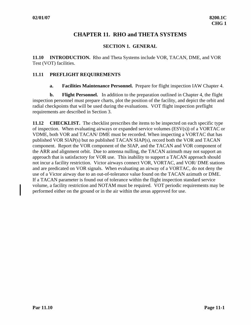
02/01/07 8200.1C CHG 1
Par 11.10 Page 11-1
CHAPTER 11. RHO and THETA SYSTEMS
SECTION 1. GENERAL 11.10 INTRODUCTION. Rho and Theta Systems include VOR, TACAN, DME, and VOR Test (VOT) facilities. 11.11 PREFLIGHT REQUIREMENTS
a. Facilities Maintenance Personnel. Prepare for flight inspection IAW Chapter 4.
b. Flight Personnel. In addition to the preparation outlined in Chapter 4, the flight inspection personnel must prepare charts, plot the position of the facility, and depict the orbit and radial checkpoints that will be used during the evaluations. VOT flight inspection preflight requirements are described in Section 3. 11.12 CHECKLIST. The checklist prescribes the items to be inspected on each specific type of inspection. When evaluating airways or expanded service volumes (ESV(s)) of a VORTAC or VDME, both VOR and TACAN/ DME must be recorded. When inspecting a VORTAC that has published VOR SIAP(s) but no published TACAN SIAP(s), record both the VOR and TACAN component. Report the VOR component of the SIAP, and the TACAN and VOR component of the ARR and alignment orbit. Due to antenna nulling, the TACAN azimuth may not support an approach that is satisfactory for VOR use. This inability to support a TACAN approach should not incur a facility restriction. Victor airways connect VOR, VORTAC, and VOR/ DME stations and are predicated on VOR signals. When evaluating an airway of a VORTAC, do not deny the use of a Victor airway due to an out-of-tolerance value found on the TACAN azimuth or DME. If a TACAN parameter is found out of tolerance within the flight inspection standard service volume, a facility restriction and NOTAM must be required. VOT periodic requirements may be performed either on the ground or in the air within the areas approved for use.
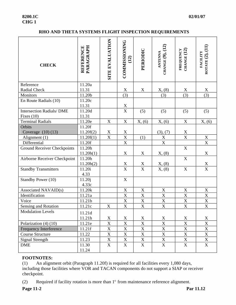
8200.1C 02/01/07 CHG 1
Page 11-2 Par 11.12
RHO AND THETA SYSTEMS FLIGHT INSPECTION REQUIREMENTS
CHECK
RE
FE
RE
NC
E
PA
RA
GR
AP
H
SIT
E E
VA
LU
AT
ION
CO
MM
ISS
ION
ING
(1
2)
PE
RIO
DIC
AN
TE
NN
A
CH
AN
GE
(9),
(12
)
FR
EQ
UE
NC
Y
CH
AN
GE
(12)
FA
CIL
ITY
R
OT
AT
E (2
), (1
1)
Reference Radial Check
11.20a 11.31
X
X
X, (8)
X
X
Monitors 11.20b (3) (3) (3) (3) En Route Radials (10) 11.20c
11.31
X
Intersection Radials/ DME Fixes (10)
11.20d 11.31
X
(5) (5) (5) (5)
Terminal Radials 11.20e X X X, (6) X, (6) X X, (6) Orbits Coverage (10) (13)
11.20f 11.20f(2)
X
X
(3), (7)
X
Alignment (1) 11.20f(1) X X (1) X X X Differential 11.20f X X X Ground Receiver Checkpoints 11.20h
11.20h(1)
X
X
X, (8) X
X Airborne Receiver Checkpoint 11.20h
11.20h(2)
X
X
X, (8) X
X Standby Transmitters 11.20i
4.33 X X X, (8) X X
Standby Power (10) 11.20j 4.33c
X
Associated NAVAID(s) 11.20k X X X X X Identification 11.21a X X X X X Voice 11.21b X X X X X Sensing and Rotation 11.21c X X X X X X Modulation Levels 11.21d
11.21h
X
X
X
X
X
X Polarization (4) (10) 11.21e X X X X X X Frequency Interference 11.21f X X X X X X Course Structure 11.22 X X X X X X Signal Strength 11.23 X X X X X X DME 11.30
11.24 X X X X X X
FOOTNOTES: (1) An alignment orbit (Paragraph 11.20f) is required for all facilities every 1,080 days, including those facilities where VOR and TACAN components do not support a SIAP or receiver checkpoint.
(2) Required if facility rotation is more than 1 from maintenance reference alignment.
02/01/07 8200.1C CHG 1
Par 11.12 Page 11-3
(3) Maintenance request.
(4) TACAN requirement – Check and report polarization on at least one radial.
(5) Fixes depicted on a SIAP in final approach segment must be evaluated concurrently with the SIAP.
(6) Check final approach segment of the SIAP(s). SID(s), STAR(s), and DP(s) are not required.
(7) First time replacement with a new type antenna, such as a Low Power TACAN Antenna (LPTA) or DOD OE-258 electronic antenna requires a coverage orbit and revalidation of all ESV(s)supporting a procedure.
(8) Evaluate on DME antenna change (same type antenna).
(9) Also applies to a RANTEC TACAN Modulation Generator change.
(10) One transmitter only.
(11) For a Magnetic Variation Change, use the facility rotation checklist.
(12) VOR Polarization – Check at least one radial in each quadrant.
(13) ESV(s) must be revalidated any time a coverage orbit is required by this order.
SECTION 2. VHF OMNIRANGE (VOR) and TACAN/ DME
FLIGHT INSPECTION SPECIFICATIONS 11.20 FLIGHT INSPECTION SPECIFICATIONS. An approved automated flight inspection system (AFIS) is the preferred method for conducting a facility flight inspection using procedures contained in appropriate agency directives. If a theodolite is used to evaluate facility performance, it must be positioned and operated by a properly trained operator. The theodolite azimuth bearings must be referenced to magnetic bearings “from” the facility. Prior to performing the checks listed below, sensing and rotation must be verified.
a. Reference Radial Check. A reference radial must be established when establishing an orbital reference and evaluated during subsequent checks. An approach radial is recommended as the reference. When course roughness and scalloping occur during an alignment evaluation, the graphic average of the deviations must be used. This reference will be used for subsequent checks of course alignment and airborne monitor reference evaluation. Determine DME accuracy as described in Paragraph 11.31.
(1) Following an antenna change, optimize the orbital alignment, then
re-establish the reference.
(2) During a periodic evaluation, if the alignment is found more than 1 than previously established, perform an alignment orbit. If the orbit remains satisfactory, find a new radial that better represents the orbital alignment, and re-establish both the reference radial and alignment orbit. Notify Maintenance when the ARR and orbit are re-established.
8200.1C 02/01/07 CHG 1
Page 11-4 Par 11.20b
b. Monitor Reference Evaluation
(1) The monitor reference evaluation determines the minimum amount of azimuth course shift required to activate the ground facility monitor alarm system.
(2) Monitor reference may be established either in the air or on the ground. Once established, the check must become the reference for all subsequent checks. The procedure for establishing a monitor reference is as follows:
(a) With the course in the normal operating condition.
(b) With the course shifted to the monitor reference point.
(c) With the course shifted to the monitor reference point in the opposite direction from Step (b) above.
(d) With the course returned to the normal operating condition.
NOTE: Step (d). There is no requirement that the course return to the measurement in Step (a). Monitor shifts of more than 1 will be brought to the attention of appropriate engineering personnel to determine if environmental or equipment related.
In each of these conditions, the course alignment will be compared by reference to recorded data to determine the amount of shift to the alarm point and to verify that it has returned to a normal condition.
(3) Facilities that have dual parallel monitors require a monitor evaluation
on one transmitter only. Facilities that have two individual monitors require evaluations on each transmitter.
c. En Route Radials
(1) FISSV. Radials flown to determine the facility's ability to support the FISSV must be flown at a minimum altitude of 1,000 ft (2,000 ft in designated mountainous terrain) above the site elevation, or the highest terrain or obstruction, to a distance of 40 miles for “L” and “H” class facilities, or 25 miles for "T" class facilities. The 40-mile or 25-mile distances are considered the standard flight inspection coverage distances.
(2) All radials supporting instrument flight procedures must be checked for signal quality and accuracy. Fly Airways, Off-Airway Routes, or route segments throughout the length of the intended use, at or below the minimum requested altitudes. If these radials have procedural requirements beyond the Flight Inspection Standard Service Volume (FISSV) distance, they must be inspected to the additional distances at the minimum requested altitudes.
(3) Changeover Points. The minimum en route altitude (MEA) for an airway change-over point (COP) must be the altitude where usable signals exist from the supporting stations. There is no requirement to check coverage beyond the COP.
9/14/09 8200.1C Chg 2
Par 11.20c Page 11-5
(4) Evaluate azimuth alignment, course sensitivity or modulations, polarization, roughness and scalloping, bends, identification, voice features, sensing, and signal strength while flying the desired azimuth.
d. Intersection Radials/ DME Fixes
(1) Intersections are used to identify azimuth positions in space. These intersections can be used for navigational fixes, reporting points, DME fixes, COP(s), etc. Establish a minimum reception altitude (MRA) for each intersection that does not meet the minimum en route IFR altitude (MEA). The MRA is the lowest altitude where reliable signals can be received within the procedural design area.
(2) Fixes located within the FISSV. When fixes are located within the FISSV, coverage throughout the fix displacement area can be predicted (fix displacement evaluation is not required). Inspect these fixes for azimuth alignment, course sensitivity or modulations, identification, roughness and scalloping, and signal strength along the radial track used to define the fix at the proposed procedural use altitude.
NOTE: Flight inspection of ESV is described in Chapter 22 of this order.
e. Terminal Radials/ Fixes (Approach, Missed Approach)
(1) Evaluate all the radial segments that comprise the STAR, SID/ DP, or SIAP on commissioning and frequency change inspections. All final segments must be flown in the direction of intended use. Ensure the procedure is compatible with human factors (see Paragraph 6.15c) and the navigational guidance is satisfactory. On commissioning and frequency change inspections, the radials must be evaluated to include the holding patterns, procedure turns, approach and missed approach, or departure routings. During periodic, antenna change, and facility rotation inspections evaluate only the final approach segment of the SIAP(s). Evaluate other terminal radials on a surveillance basis.
(2) All evaluations must be conducted at the procedural altitudes except the final approach segment. This segment is evaluated from the FAF (or final descent point) descending to 100 ft below the lowest MDA to the MAP. During site, commissioning, reconfiguration, antenna change, frequency change, and applicable changes to the final approach segment, evaluate VOR radials 5 on each side of the final approach radial. Evaluate the offset VOR radials on one transmitter at the same altitudes as the final approach radial segment.
(3) When terminal fixes are located within the facility’s FISSV or below the FISSV but within the standard service volume, coverage, throughout the fix displacement area, can be predicted (fix displacement evaluation is not required).
(4) During a periodic evaluation, verify that the crossing radial identifying the fix supports the procedure. Verification may be by recording trace or analysis of the cockpit instrumentation. There is no requirement to evaluate the fix displacement area.
8200.1C 02/01/07 CHG 1
Page 11-6 Par 11.20e
(5) TACAN Azimuth Null Checks will be flown as follows:
(a) Approved Procedure
1 On commissioning inspections, antenna change, new procedures, and changes in FAF altitude of 300 ft or more on existing procedures, the following null checks are required:
a Approach radial
b 5 either side of the approach radial
The radials will be flown inbound or outbound on a level flight from 3 miles outside the final approach fix (FAF) to 3 miles inside the FAF at the lowest minimum altitude for FAF.
(b) Nulls, defined as any repeatable out-of-tolerance crosspointer action or condition of unlock usually accompanied by rapid changes in the automatic gain control (AGC) and oscilloscope indications of a loss or distortion of the 15 and 135 cycle modulation components, are not permitted in this area. If a null is found, measure the vertical angle by flight in the area described above at an altitude 500 ft above or below the minimum FAF altitude, and inform Maintenance so that the problem can be corrected if possible. If the null cannot be corrected by antenna change or height adjustment, a new procedure will be developed which will avoid the affected area. Null checks are required on only one transponder. Due to the effect of the station cone on azimuth performance, null checks are not required when the TACAN facility is located at the FAF.
(6) Commissioning Inspections. On commissioning inspections, missed approach, and SID/ DP radials for facilities located within the airfield, boundary must be evaluated from overhead the station outbound to the limits depicted for the procedure. If no termination point is depicted, the radial must be checked to where it joins the en route structure or the expected coverage limit of the facility category, i.e., 25 miles for a “T” class and 40 miles for “L” or “H” class facilities.
(7) Evaluate the radials for signal quality and accuracy. The final approach course must deliver the aircraft to the desired aiming point. Evaluate azimuth alignment, course sensitivity or modulations, polarization (when within 5 to 20 nm of the station), roughness and scalloping, bends, identification, and signal strength when flying the radials. Evaluate the 5 offset radials for course sensitivity or modulations, roughness and scalloping, spectrum analysis, identification, and signal strength.
(8) Facility Rotation for MAGVAR Change Inspection. Evaluate one TACAN null and VOR offset radial 5 beyond the final approach radial, IAW Paragraph 11.20e(2), to ensure a minimum of 5 has been checked each side of the published final approach radial. For example, when the published approach radial is changed from R090 to R087, based on a MAGVAR change from 2 East to 5 East, fly R082 as the null/ offset radial. R095 will have been flown previously to support the R090 approach, and provides the 5 minimum requirement. Ensure the published facility restriction, receiver checkpoint, and ESV radials, changed per the facility rotation check, are reported on the flight inspection report.
02/01/07 8200.1C CHG 1
Par 11.20f Page 11-7
f. Orbit Evaluations. Orbit evaluations are used to determine azimuth error distribution and signal quality. Orbit data are used as reference information. Establish reference alignment during commissioning, antenna change, frequency change, facility rotation, if no orbital reference exists, or if the ARR and alignment orbit dates on the AVNIS Data Sheet do not match. Evaluate for deviation from the reference during all subsequent orbital evaluations. When optimizing alignment, the mean orbital alignment should be within 0.5, and the system differential between a collocated VOR and TACAN should not exceed 1. For dual transmitter systems, use the primary transmitter as the reference. Inform maintenance when alignment references are established/ re-established. Notification may be accomplished through Flight Inspection Central Operations if maintenance is not on site and/or abnormal delays occur.
(1) Alignment Orbit
(a) The alignment orbit is used to determine the accuracy and optimum error distribution of the azimuth. The evaluation is conducted for 360 of azimuth. An orbit radius of 5 nm and beyond may be used when using GPS hybrid or equivalent for updating and 10 nm and beyond when using distance measuring equipment updating. When using theodolite, the orbit radius must be the maximum visual range for the theodolite operator. The orbit may be flown clockwise (CW) or counterclockwise (CCW), but once established, it must be flown in the same direction, at the same distance and altitude, on each subsequent inspection. Compute a tapeline altitude to fly the orbit at a standard angle of 4 to 6 from the site. The objective of the check is to help Facilities Maintenance personnel determine environmental problems close in to the facility. The ratio between distance and altitude becomes critical when looking for low angle reflections or shadowing. Altitudes and distance may be modified when conditions prevent establishing them at the recommended 4 to 6 (air traffic requirements, engineering or maintenance support, and site conditions). Indicate deviations from the standard on the flight inspection report and Facility Data Sheet.
(b) If alignment cannot be determined orbitally, it may be measured by flying one radial in each quadrant. A partial orbit, augmented with radial alignment, is preferred over alignment determined solely by radial means. Notify the Flight Inspection Policy Team if the use of radial flight is accomplished in lieu of orbital alignment.
(c) One orbit may be flown on dual transmitter facilities during any inspection, except commissioning, by requesting transmitter changes. If sufficient transmitter changes cannot be accommodated (at least one in every 40o), fly an orbit on each transmitter.
(d) During the orbit, evaluate azimuth alignment, course sensitivity or modulations, sensing and rotation, roughness and scalloping, identification, and signal strength (a minimum of 1 evaluation every 20). Out-of-tolerance conditions found during an orbital inspection must be confirmed by a radial evaluation before restricting a facility or issuing a NOTAM. The radial evaluations normally have priority.
(e) Course error distribution must be determined prior to rotation (if required) to achieve optimum station balance. It is not necessary to refly the orbit after this facility rotation, provided the direction and magnitude of the adjustment can be confirmed radially. Apply the confirmed azimuth shift to the alignment orbit for final error spread determination and plotting. Complete the remaining facility rotation checklist items after the rotation.

8200.1C 02/01/07 CHG 1
Page 11-8 Par 11.20f
(f) Course Alignment. On periodics, if a change in mean course alignment of more than 1 is found, contact Facilities Maintenance. Facilities Maintenance will conduct an evaluation to determine if the change in the facility was caused by a maintenance problem or caused by an environmental change.
(2) Coverage
(a) This check is conducted to determine the facility’s ability to support the Flight Inspection Standard Service Volume (FISSV). The FISSV must be established as follows: On “T” class facilities, the FISSV is 25 nm and 1,000 ft above facility antenna elevation, or the minimum altitude which will provide 1,000 ft (2,000 ft in designated mountainous areas) above intervening terrain as determined by map study. On “L” and “H” class facilities, the distance extends to 40 nm, and the altitudes are the same as for the “T” class. Establish facility restrictions and performance status based on the FISSV. One complete orbit (one transmitter only) must be flown at either:
1 The applicable FISSV
2 Altitudes high enough to receive in-tolerance signals. If these altitudes are higher than the altitudes in paragraph (1) above, facility restrictions and NOTAM action are required.
(b) During the orbit, evaluate azimuth alignment, course sensitivity or modulations, sensing and rotation, roughness and scalloping, identification, and signal strength (a minimum of 1 evaluation every 20).
(c) Out-of-tolerance conditions discovered during orbital inspections must be confirmed by a radial inspection before restricting a facility or issuing a NOTAM. An orbit segment used to establish a restriction may be defined laterally by orbital means. Radials flown through the most severe out-of-tolerance area may be used to define the distance and altitude limits of the entire segment. The radial inspection results normally have priority over orbital inspection data. In areas of multiple restricted segments, it may be appropriate to group those segments into larger, easier to understand restrictions. The advantages of this possible over-restriction in some areas must be weighed against user requirements. Fly an arc at the FISSV of the facility at the restricted altitude to encompass the restricted area to determine usable signal coverage.
(d) Procedures flown below or outside the FISSV, which are found unsatisfactory, must be denied, but a facility restriction is not required.
g. Expanded Service Volumes (ESV(s)) are required only when procedural use is predicated on a NAVAID’s performance outside of the SSV, as illustrated in Appendix 3, Figures A3-5A – F. Evaluate ESV(s) on one transmitter only. When required, an ESV may be revalidated by orbital flight at the ESV distance and lowest approved altitude. Lateral limits of the area should encompass allowable radial misalignment or applicable fix displacement area. There is no need to inspect the upper limits of an ESV unless interference is reported or suspected.
02/01/07 8200.1C CHG 1
Par 11.20g Page 11-9
In most applications, the VOR is the primary facility supporting procedural use (i.e., airways, fixes, intersections). When evaluating facilities supporting procedural uses, record all component signals. If any NAVAID component (i.e., VOR, TAC, or DME) does not meet flight inspection parameter tolerances, document the results as follows.
(1) Within the applicable 25 or 40 nm flight inspection service volume, complete the appropriate flight inspection report form(s) and restrict the NAVAID accordingly.
(2) Beyond the applicable flight inspection service volume but within the SSV, complete the appropriate flight inspection report form(s) and document flight inspection results on the procedures package forms. No facility restriction is required.
(3) Beyond the applicable SSV, complete the appropriate flight inspection form(s), ESV forms, noting the component(s) which will not support the ESV, and document the results on the procedures package forms. No facility restriction is required.
For flight inspections beyond the applicable 25 or 40 nm distance, complete only the fields of the flight inspection report forms for the NAVAID components identified for procedural use.
h. Receiver Checkpoints are established to allow pilots to check the accuracy of their receivers. Inability of a facility to support receiver checkpoints must not result in facility restrictions.
(1) Ground Receiver Checkpoints will be established on the airport ramp or taxiways at points selected for easy access by aircraft, but where there will be no obstruction of other airport traffic. They normally will not be established at distances less than one-half mile from the facility, nor should they be established on non-paved areas. All azimuth bearings must be stable and within prescribed azimuth tolerance. Evaluate azimuth alignment, course sensitivity or modulations, roughness and scalloping, identification, and signal strength. If a stable signal and alignment cannot be obtained at a location, select another site or establish an airborne receiver checkpoint. Ensure that surface markings and signage are correct. Observed slight variances in airport surface markings and signage should not affect their acceptability unless, in the judgment of the flight inspector, they could affect the usability of the checkpoint.
(2) Airborne Receiver Checkpoints must be designated over prominent ground checkpoints. It is preferred that such checkpoints be near an airport so they are easily accessible to users and must be at least 1,000 ft AGL. The checkpoint should not be established at a distance less than 5 miles or more than 30 miles from the facility. However, consideration should be given to selecting an area and altitude that will not interfere with normal traffic patterns. The electronic radial overlying the geographic checkpoint, rounded off to the nearest whole degree, will be the azimuth published as the receiver checkpoint.
i. Standby Transmitters. Both transmitters must be evaluated for each required checklist item, except the coverage orbit and ESV(s), which are required on one transmitter only. Alignment evaluations may be made by changing transmitters during an evaluation and comparing the azimuth course shift. Transmitter changes must not be made inside the final approach fix; however, transmitter changes made before the final approach fix are satisfactory for evaluation purposes. If comparison results are questionable, fly the approach segment on each transmitter.

8200.1C 02/01/07 CHG 1
Page 11-10 Par 11.20j
j. Standby Power (reference Paragraph 4.33c)
(1) The following checklist items will be inspected while operating on standby power (one transmitter only need be checked):
(a) Course alignment (one radial)
(b) Course structure
(c) Identification
(d) Distance accuracy
(2) The inspections are to be performed when flying a portion of a radial with the station operating on normal power and then repeating the check over the same ground track with the station operating on standby power.
k. Associated Facilities
(1) Inspect associated facilities concurrently with the inspection of the primary facility. These include marker beacons, lighting aids, communications, etc., which support the en route/ approach procedures and landing weather minimums of an associated approach procedure.
(2) Conduct inspections of these facilities in conformance with the detailed specifications and tolerances contained in the applicable section of this manual.
l. Crossing Radials. When a crossing radial is used to define a point in space (i.e., IAF, FAF, etc.), there is no requirement to fly it radially. The evaluation of the crossing radial is accomplished while the aircraft remains on the procedural track.
(1) For a commissioning or reconfiguration evaluation, or new procedure development, the crossing radial must be verified by recording trace analysis for azimuth alignment, course sensitivity or modulation, identification, roughness and scalloping, and signal strength. (Alignment may be determined by manual crosspointer analysis of the crossing radial at the fix.) If the fix is not contained within the FISSV of either facility, an ESV must be established to support the procedure.
(2) For a periodic evaluation, verification may be accomplished by recording trace or analysis of the cockpit instrumentation. 11.21 ANALYSIS
a. Identification (ID). This check is made to ensure the identification is correct and is usable throughout the operational service volume.
(1) Specifications. Evaluate the identification during all checks. The facility must be restricted if the identification is not usable in all areas of required coverage.

02/01/07 8200.1C CHG 1
Par 11.21a Page 11-11
(2) Identification Sequence
(a) VOR(s), VOR/ DME(s), and VORTAC(s) with VOR voice identification using dual voice code reproducers at dual location or single voice code reproducer at single VOR location uses the following sequence:
Identification on VOR in code. Identification on VOR by voice. Identification on VOR in code. Identification on TACAN/ DME at the normal time for voice identification on the VOR.
(b) VOR(s), VOR/ DME(s), and VORTAC(s) with VOR voice identification using single voice code reproducer with dual VOR equipment: The identification sequence is the same as in Paragraph (a) above; however, synchronization will not exist between the TACAN and VOR identification. Voice identification may be heard with the keyed ident, and the flight inspector must determine from an operational standpoint if the identification is clear and that the course is not adversely affected.
(c) VOR(s), VOR/ DME(s), and VORTAC(s) without VOR voice identification uses the following sequence:
Identification on VOR in code. Blank Identification on VOR in code. Identification on TACAN/ DME at the normal time for code
identification on the VOR.
(3) Identification is a series of coded dots and dashes and/or voice identification transmissions that amplitude modulate the VOR RF carrier frequency. The ID enables a user to identify the VOR station.
(4) Evaluate the ID signals for correctness, clarity, and to ensure there is no adverse effect on the azimuth course structure. When it is difficult to determine what effect the ID has on the azimuth course structure because of roughness and scalloping, evaluate the same azimuth radial with the ID off and compare the results. When simultaneous voice and Morse coded ID are installed, the modulation levels are adjusted so both audio levels sound the same. These levels are approximately 30 and 8 percent, respectively.
When a voice broadcast feature is installed (ATIS, AWOS, etc.), the voice ID feature is suppressed during voice transmissions, but the Morse coded ID should still be heard. The Morse coded ID signals must be identifiable throughout the entire unrestricted VOR coverage area, including ESV(s). When the identification is unacceptable, take appropriate NOTAM action and notify Facilities Maintenance.
(5) For facilities with standby transmitters and separate standby ID equipment, use the Morse coded ID to identify each transmitter. The number one transmitter has equal spacing between all characters of the coded identification. The spacing between the second and third characters of the number two transmitter is increased by one dot.
8200.1C 02/01/07 CHG 1
Page 11-12 Par 11.21b
b. Voice
(1) The voice broadcast feature, when installed, allows a user to receive radio communications, weather and altimeter information, air traffic and airport advisories, etc., on the VOR frequency. Voice amplitude modulates the VOR carrier frequency by 30 percent.
(2) Inspect the voice for clarity to ensure there is no adverse effect on the azimuth course. Ensure that all published remote sites can respond on the VOR frequency when contacted. Maintain a periodic surveillance of the quality and coverage of the voice transmissions throughout the VOR coverage area.
(3) Advisory services that provide voice broadcast features include ATIS, AWOS, ASOS, TWEB, and HIWAS. Some services may not be continuously available. Inspect only the services available.
(4) When the voice transmissions are unsatisfactory, but the remainder of the VOR operation is satisfactory, NOTAM only the voice feature out of service. When the voice modulation adversely affects the VOR operations, the voice portion must be disabled and NOTAMed out of service, or the VOR must be NOTAMed out of service.
c. Sensing and Rotation
(1) The sensing and the following rotation check are required at the beginning of the flight inspection. The position of the aircraft on a radial from the station must be known. Select the azimuth of the radial being flown. When the crosspointer is centered, the “TO – FROM” indicator will properly indicate “FROM” if sensing is correct. For AFIS-equipped aircraft, compare the computer-generated bearing. Sensing should be checked before rotation, as incorrect sensing may in itself cause the station rotation to appear reversed. See Appendix 3.
(2) Rotation. Upon completion of the sensing check, conduct a partial orbit. The radial bearings must continually decrease for a counterclockwise orbit or continually increase for a clockwise orbit. This check may be satisfied by visually observing either cockpit or AFIS azimuth indications.
d. Modulation Levels
(1) The three individual modulation levels associated with the VOR are: 30 Hz AM, the 30 Hz FM (or deviation ratio of the 9960 Hz subcarrier), and the 9960 Hz AM modulation of the VOR RF carrier.
(a) 30 Hz AM is optimized at 30% and is termed the “variable phase” on conventional VOR(s).
(b) 30 Hz FM (a deviation ratio of 16 is equivalent to 30% modulation value) is termed the “reference phase” on a conventional VOR. On Doppler VOR(s), it is termed the “variable phase”.
(c) 9960 Hz AM is optimized at 30%. The 9960 Hz amplitude modulation of the VOR RF carrier may cause receiver flag warnings when out of tolerance.

02/01/07 8200.1C CHG 1
Par 11.21d Page 11-13
(2) Analysis. Adjustments of modulation values may be made on any radial (within 10 to 25 miles of the facility). Modulation values must meet operational tolerances throughout the unrestricted service volume of a VOR. Determine the average modulation values or the graphical average of the recorded modulation values (when available) when fluctuations are encountered.
e. Polarization causes azimuth course variations whenever the aircraft is banked around its longitudinal axis. It is caused by the radiation of a vertically polarized signal from the VOR antennas (horizontal polarization on TACAN) or other reflective surfaces around the site. The indications are similar to course roughness and scalloping, but normally can be separated by relating the course deviations to the aircraft banking. When roughness and scalloping cannot be separated from polarization, select another radial. The evaluations should be conducted on another nearby radial in the same azimuth quadrant.
(1) Evaluation. Polarization should be evaluated any time a radial is checked and within 5 to 20 miles (inbound or outbound) from the facility. Only one radial is required for TACAN. The preferred method of evaluating for polarization is to bank the aircraft 30 around the longitudinal axis (starting on either side) returning to level flight momentarily, bank 30 in the opposite direction and returning to straight and level flight. During the aircraft banking, the tracking and heading changes must be kept to a minimum. The course deviations that occur during the 30rolls may indicate polarization.
The indications of polarization may be influenced by course roughness and scalloping. A confirmation check is required if out-of-tolerance conditions are discovered using this method.
(2) Confirmation Procedure. Fly over a prominent ground checkpoint, located 5 – 20 miles from the facility. Execute a 30 bank and turn, holding this attitude through 360. End this maneuver as close to the same ground checkpoint as possible. Mark the recording at the beginning and end and at each 90 change in azimuth heading. If polarization is not present, the course will indicate a smooth departure from and return to the “on-course” position, deviating only by the amount that the aircraft is displaced from the original azimuth.
f. Frequency Interference
(1) The RF electromagnetic spectrum from 108 to 118 MHz is reserved for VOR and ILS localizer signals. Undesirable RF signals can be radiated in this frequency band that interfere with the VOR signals. Electromagnetic interference (EMI) signals can be produced by electrical manufacturing processes, power-generating facilities, etc., which may be sporadic. Radio frequency interference (RFI) may be caused by other VOR(s), harmonics of other frequencies, FM stations, etc., which are usually continuous.
(2) The VOR spectrum must be monitored for undesirable electromagnetic radiation when RF interference is suspected. When interfering radiation is observed, it is not justification for restricting the facility, unless other flight inspection tolerances are exceeded. Undesirable signals must be reported to Facilities Maintenance.

8200.1C 02/01/07 CHG 1
Page 11-14 Par 11-21f
(3) Facility restrictions and NOTAM(s), established by Spectrum Management, must be identified on the Facility Data Sheet. These restrictions must not be removed by flight inspection alone.
g. TACAN Analysis. The oscilloscope, TACAN Test Set, or AFIS display/ plots) should be used for analysis of TACAN signals. The following are suggested analytical procedures, and no facility restrictions are to be applied if adjustment cannot be made or if maintenance personnel are not available for adjustment. The composite video, when displayed on the oscilloscope, will yield considerable data about the TACAN facility. The following video parameters may be measured:
(1) 15 Hz modulation
(2) 135 Hz modulation
(3) Identification train
(4) Reflections
(5) MRG size
(6) Auxiliary Reference Group (ARG) size
(7) ARG count
h. Modulation Percentage 135 and 15 Hz. Measure the modulation of each component and calculate the percentage Notify maintenance if modulation limits are exceeded.
(1) Modulation measurements are more easily and accurately made via the TACAN Test Set or AFIS. The oscilloscope should be used only when other options are not available.
(2) Identification Train. To measure the ident spacing group, adjust the oscilloscope so that the main burst is on the left edge of the graticule and the first auxiliary burst is on the right edge. When the ident is on, the reference bursts, the ident groups become very evenly spaced, and a group should appear on each division line.
(3) Reflections. Reflected signals may be detected by examining the composite video. Reflections, when present, may duplicate the normal pattern in an image pattern slightly displaced to the right. Reflections may be of sufficient amplitude to cause the pattern amplitude to oscillate or cause the modulation percentage to oscillate at a sine wave frequency dependent on velocity and position of the aircraft.
(4) Main Reference Group Size. Size refers to the number of pulse pairs in a group. For “X” channel, there should be 12 pulse pairs in the main reference group spaced 30 usec apart with spacing of each pulse in a pair of 12 usec. For “Y” channel, there are 13 single pulses in the MRG spaced 30 usec apart. If the TACAN test set indicates a discrepancy in the group size, use of the oscilloscope will identify the trouble. Advising maintenance of the condition found may ease their task of correcting the problem.
02/01/07 8200.1C CHG 1
Par 11.21h Page 11-15
(5) Auxiliary Reference Group Size. Size refers to the number of pulse pairs in an auxiliary reference group. For “X” channel, there should be six pulse pairs spaced 24 usec apart with spacing of each pulse in a pair of 12 usec. For “Y” channel, there are 13 single pulses in a group spaced 15 usec apart. If the TACAN test set indicates a discrepancy in the group size, use of the oscilloscope will identify the trouble. Advising maintenance of the condition may ease their task of correcting the problem.
(6) Auxiliary Reference Group Count. Count refers to the number of auxiliary reference groups between North reference bursts or groups. There are eight auxiliary reference groups between North reference bursts. If the TACAN test set shows the loss of auxiliary reference groups, use of the oscilloscope will quickly identify the exact problem. Advising maintenance of the condition may ease their task of correcting the problem.
(7) Operational Limits. Measurements should fall within the following limits:
Parameters Limit Remarks 15 Hz Modulation 10 – 30% Inform maintenance if graphical average exceeds
limits 135 Hz Modulation 10 – 30% Inform maintenance if graphical average exceeds
limits Identification pulse spacing
740 microseconds
Synchronized with burst.
Reflections N/A No derogation of facility performance. MRG size 12 1 pulse pair ARG size 6 1 pulse pair ARG count 8 0 burst 11.22 COURSE STRUCTURE
a. Roughness, scalloping, and bends are displayed on the recorder charts as deviations of the crosspointer (course deviation indicator) recording trace. Roughness will show a series of ragged irregular deviations; scalloping as a series of smooth rhythmic deviations; and the frequency of each is such that it is not flyable and must be “averaged out” to obtain a course.
b. To measure the amplitude of roughness and scalloping, or the combination, draw two lines on the recording which are tangential to and along each positive and negative peak of the course deviation. The number of degrees or microamperes between these lines will be the total magnitude of course deviations; one-half of this magnitude will be the plus and minus deviations.
c. Draw a third line equidistant from these lines to obtain the average “on course” from which course alignment is measured. Thus, the instantaneous alignment error of the course may be computed from the course recordings at any point where an accurate checkpoint has been marked on the recording. Alignment error will be referred to in degrees to the nearest tenth. Misalignment in a clockwise direction is considered positive. Where the magnetic azimuth of the measured (ground) checkpoint is greater than the electronic radial, the error is positive. (See Figure 11-2.)
8200.1C 02/01/07 CHG 1
Page 11-16 Par 11.22d
d. A bend is similar to scalloping except its frequency is such that an aircraft can be maneuvered throughout a bend to maintain a centered crosspointer. Accordingly, a bend might be described as a brief misalignment of the course. Bends are sometimes difficult to discern, especially in those areas where good ground checkpoints or other means of aircraft positioning are not available. It is, therefore, important to the analysis of a bend to consider aircraft heading and radial alignment deviations. A smooth deviation of the course over a distance of 2 miles would manifest itself as a bend for a flight inspection aircraft at a ground speed of 150 knots. An aircraft of greater speed would not detect such smooth deviations of the course as a bend unless it was over a greater distance. In the analysis of bends, further consideration should be given to the flight levels and speeds of potential users. Since speed, altitude, system response, and other factors are important in the analysis of course structure, the flight inspector should carefully evaluate the flyability factor before assigning a final facility classification.
e. Application of Tolerances
(1) The alignment of a radial is the long-term average of the data points derived by eliminating the short-term variations of roughness and scalloping and bends. Bends and the length of the measurement distance influence the measured alignment. A short measurement segment may sample only an area that is really a bend when compared to a longer measurement segment. Flight inspectors must consider the procedural needs of the radial and measure enough of the radial to define alignment in the procedural use area. Thus, a short radial segment used for an approach may be unsatisfactory due to a bend being correctly analyzed as alignment when an identical bend would be correctly analyzed as a bend from the overall alignment of a longer airway radial segment.
(2) The displacement of the course by a bend must not exceed 3.5 from either the correct magnetic azimuth or the average “on course” provided by the facility. The following two examples are offered for clarification:
(a) A radial having zero alignment error. The maximum bend tolerance of 3.5 is allowable both sides of the “on course”, whether the bends occur singly or in a series.
(b) A radial having an alignment error of +2.0. Further displacement of the course by a bend of +1.5 is allowable: this results in a +3.5 displacement from the correct magnetic azimuth. Displacement of the course of –3.5 from the average “on course” is allowable; this results in a –1.5 displacement from the correct magnetic azimuth.
(3) In the event of roughness or scalloping, or combination, superimposed on the bend, the average “on course” must be determined by averaging the total amplitude of such aberrations. This can result in a momentary displacement of the course of 6.5 where 3.0 of roughness is superimposed on a bend of 3.5.
(4) The criteria for roughness and scalloping must not be applied strictly as a plus and a minus factor from the average course. Where it is apparent that a rapid deviation occurs only on one side of the course rather than in a series, the criteria must be applied as a plus or minus factor.
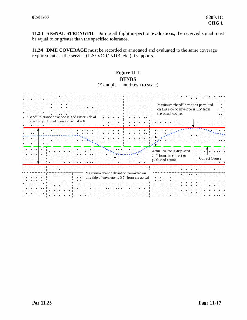
02/01/07 8200.1C CHG 1
Par 11.23 Page 11-17
11.23 SIGNAL STRENGTH. During all flight inspection evaluations, the received signal must be equal to or greater than the specified tolerance. 11.24 DME COVERAGE must be recorded or annotated and evaluated to the same coverage requirements as the service (ILS/ VOR/ NDB, etc.) it supports.
Figure 11-1
BENDS (Example – not drawn to scale)
Actual course is displaced 2.0 from the correct or published course.
Maximum “bend” deviation permitted on this side of envelope is 3.5 from the actual
“Bend” tolerance envelope is 3.5 either side of correct or published course if actual = 0.
Maximum “bend” deviation permitted on this side of envelope is 1.5 from the actual course.
Correct Course

8200.1C 02/01/07 CHG 1
Page 11-18 Fig 11-2
Figure 11-2
STRUCTURE (Example – not drawn to scale)
ROUGHNESS - SCALLOPING SCALLOPING
-3.5
+3.0 +6.5
-3.0 -3.0
AVERAGED “0” ALIGNMENT
+3.5.BEND
ROUGHNESS – SCALLOPING-BENDS AND COMBINATIONS
+ 3.0 + 3.0
3.5 = Maximuum bend
6.5 = Max Roughness/scalloping and bend
3.0 = Maximum R/S
SCALLOPING ROUGHNESS - SCALLOPING ROUGHNESS
- 3.0 - 3.0 - 3.0
- 3.5 Bend
02/01/07 8200.1C CHG 1
Par 11.30 Page 11-19
SECTION 3. DISTANCE MEASURING EQUIPMENT (DME)
11.30 INTRODUCTION. This section provides instructions and performance criteria for certifying standard distance measuring equipment (DME). The flight inspection of DME can be performed separately but is normally checked in conjunction with the more detailed check of the associated ILS, MLS, VOR, or TACAN facility. When conducting a flight inspection of DME, independent of an associated facility, check the following:
Accuracy Identification Coverage
11.31 DISTANCE ACCURACY. Check the accuracy of the DME distance information during inspection of radials, orbits, approach procedures, and DME fixes. The exact mileage indication displayed on the distance indicators must be noted on the recordings. Comparison of the scaled distance on the chart (converted to slant range) to the distance indicated by the DME distance indicator at the various points may be made for accuracy determination.
a. It is not necessary to compute the slant range for distances measured at altitudes below a vertical angle of 5 because the relative difference between slant and chart range is negligible (less than ½ to 1 percent).
b. For ease of computation, a 5 angle is equivalent to approximately 1,000 ft above the antenna at 2 miles and 5,000’ above the antenna at 10 miles. Above a 5 angle, a DME slant range mileage must be converted to chart distance.
c. If the ground facility is emitting false reply pulses, erroneous distance information may be present. This condition usually occurs within 25 miles of the antenna. Whenever actual false lock-ons are experienced, the offending facility must be removed from service until this condition is remedied. 11.32 IDENTIFICATION. The identification must be checked for correctness and clarity, with the aircraft either in orbital or radial flight. A DME associated with an associated facility will be checked for correct synchronization of the two identification signals. 11.33 COVERAGE. DME coverage must be recorded or annotated and evaluated to the same coverage requirements as the service (ILS/ VOR/ NDB, etc.) it supports. DME fixes located outside the FISSV must be evaluated for coverage 4 nm or 4.5 (whichever is greater) at 5 nm greater than the fix distance. Coverage is validated on one transponder only.

8200.1C 02/01/07 CHG 1
Page 11-20 Par 11.40
SECTION 4. SHIPBOARD TACAN
11.40 INTRODUCTION. Flight inspection of shipboard TACAN must be performed when requested by the U.S. Navy. Due to the deployment of ships, these inspections must be considered a one-time inspection and must include all checklist items in Paragraph 11.42. 11.41 FLIGHT INSPECTION SPECIFICATIONS
a. The flight inspection must be scheduled upon receipt of the following information:
(1) Date and time of requested inspection.
(2) Name and hull number of the ship.
(3) TACAN channel.
(4) UHF primary and secondary communication frequency.
(5) Location of ships (latitude and longitude).
(6) Name and phone number of area coordinator.
b. The inspection must be conducted with the ship underway and at a distance from shore that is sufficient to preclude interference or shielding of the signal by landmass during radial and orbital inspections.
c. The ship’s radar must be used as a basis to determine alignment. Fire control radar is considered the most accurate and will be used when available. Search (CIC) radar may be used if fire control radar is not available. Fire control information is given as TRUE bearings, and search radar is MAGNETIC.
d. Due to various antenna mount positions on ships and possible shielding by other antennas, masts, etc., nulls and/or unusable sectors may occur. Suspected out-of-tolerance conditions must be confirmed by a second evaluation of the area in question. Any sector of the TACAN that does not provide azimuth or distance information must be reported immediately to the ship and documented in the flight inspection report. 11.42 CHECKLIST. The following must be inspected during shipboard inspections.
a. Identification
b. Sensing and rotation
c. Polarization
d. Radial alignment (minimum of one)
e. Coverage
f. Distance accuracy
g. Frequency interference
02/01/07 8200.1C CHG 1
Par 11.42 Page 11-21
h. Alignment orbit
i. Approach radial
j. Standby equipment
k. Stabilization
l. Checks will be completed in accordance with appropriate paragraphs of this chapter, unless modified or changed by the following:
(1) Those items normally inspected during radial flight may be accomplished on a radial to or from the ship or during inspection of the approach radial.
(2) Identification. Shipboard TACAN identification consists of two Morse code letters transmitted every 30 or 37 ½ seconds.
(3) Coverage. Check a minimum of one radial for coverage to 40 nm during inbound or outbound flight at 700 MSL. Advise the ship if coverage is less than 40 nm.
(4) Frequency Interference. All of the ship’s electronic equipment that is normally operating should be activated during the inspection.
(5) Alignment Orbit. The orbit must be flown beyond 7 nm from the ships and no lower than 700 ft MSL. On those ships using search radar (CIC) for alignment, the orbit must be flown below 2,000 ft MSL.
(6) Approach Radial. The ship’s approach radial is the radial that will guide the aircraft to the stern of the ship and will vary depending on the heading of the ship. Fly the radial from a minimum of 7 nm and 700 ft MSL to pass over the ship at 300 ft MSL. Determine and report radial alignment and structure.
(7) Standby Equipment. CV, LPH, LHA, and LPD ships have dual TACAN equipment. Spot-check the standby equipment during radial flight by requesting a change from primary to standby equipment.
(8) Equipment Stability. Stability of the TACAN equipment may be affected during a turn of the ship. Stability will be checked during radial inspections by requesting the ship to turn left 15 and then right 15. Advise the ship’s personnel of any change to azimuth or alignment during the turns. 11.43 TOLERANCE. The tolerance contained in this chapter applies as appropriate to the shipboard TACAN.

8200.1C 9/14/09 Chg 2
Page 11-22 Par 11.50
SECTION 5. VOR TEST FACILITY (VOT)
11.50 INTRODUCTION. This section describes the procedure and tolerances used to inspect and certify a VOT. A VOT is a facility, which transmits a test signal that is used to determine the operational status of a VOR receiver. A “Standard VOT” is a facility intended for use on the ground. It should be checked on the ground in the area of intended use. An “Area VOT” is a facility designed for use on the ground or in the air. It may be located to provide the test signal to one or more airports. Certification of an area VOT must be based on checks of facility performance in all areas of intended use. 11.51 CHECKLIST. Perform the checks as noted below. Periodic requirements may be performed either on the ground or in the air within the areas approved for use.
Inspection Parameter Reference Paragraph C P
Frequency Interference 11.53a X X Identification 11.53b X X Sensing 11.53c X X Modulation Level 11.53d X X VOT Reference Point 11.53e X Alignment (Course Indication)
11.53f X X
Coverage 11.53g X X Monitor 11.53h (1) Standby Power 11.53i
4.33c X
FOOTNOTE: (1) Maintenance request
11.52 PREFLIGHT REQUIREMENTS. At this time, VOT(s) do not have a specified service volume. VOT service is identified and controlled by the FAA Service Area having jurisdiction of the airport where VOT service can be provided. Area VOT(s) are strategically installed to serve certain specific airports on the ground. Additional airports may be identified by the appropriate Service Area to receive airborne VOT service. The inspector must inspect those airports identified to receive ground and/or airborne service. If, as a result of the inspection, adequate VOT coverage is found at additional airports, the FAA Service Area must be notified. If they concur that the additional airports should receive VOT service, the inspector must publish the additional airports.
02/01/07 8200.1C CHG 1
Par 11.53 Page 11-23
11.53 FLIGHT INSPECTION SPECIFICATIONS. Recordings must be made on all flight inspections to provide graphic data for analysis of signal intensity and station performance. Record crosspointer, flag alarm current, identification, and AGC on all checks.
a. Frequency Interference (Spectrum Analysis). Evaluate the electromagnetic spectrum using a spectrum analyzer if interference is suspected. Record the measured frequency and detailed information on observed interference.
b. Identification. The purpose of this check is to assure that the correct tone and identification are transmitted.
(1) Two means of identification are used with these facilities—either a continuous series of dots, or a series of dots that cannot be interpreted as Morse code. Facilities Maintenance personnel should be consulted for the proper identification. For both standard and area VOT(s), check the identification for correctness, clarity, and possible effects on the course indications throughout the areas of intended use (both in the air and on the ground). Record the commissioned identification on the Facility Data Sheet.
(2) Approved Procedure. For both standard and area VOT(s), check the identification for correctness, clarity, and possible effects on the course indications throughout the areas of intended use (both in the air and on the ground).
c. Sensing. This check determines and/or establishes the correct ambiguity of the transmitted signal. While on the ground or in the air, check that the ambiguity indicates TO with 180 set in the omnibearing selector (OBS) and FROM with 360 set in the OBS, throughout the areas of intended use.
d. Modulation Level. Since minor variations of the 30 Hz AM, 30 Hz FM (Deviation Ratio), and 9960 will effect flight data, check the modulation levels throughout the areas of intended use. Measure and record modulation levels during all inspections.
(1) Specifications:
(a) Ground. Establish nominal values at the VOT reference point. Ensure that modulations remain within tolerance throughout all use areas.
(b) Airborne. Ensure that modulations remain in tolerance throughout all areas while conducting coverage maneuvers.

8200.1C 02/01/07 CHG 1
Page 11-24 Par 11.53e
e. VOT Reference Point. This check provides a designated area to begin an inspection or verify facility performance. The reference point must be documented on the Facility Data Sheet.
(1) Standard VOT. This check should be performed on the ground. It is recommended that the area chosen be the furthest distance from the facility maintaining line of sight.
(2) For ground-use standard VOT(s) at airports not accessible to flight inspection aircraft, the reference point may be evaluated utilizing a Portable ILS/ VOR Receiver (PIR). The Aviation System Standards Flight Inspection Policy Team must approve the use of these procedures on a case-by-case basis. This alternative is subject to the following conditions:
(a) Wilcox Model 7010 PIR or equivalent, capable of displaying VOR bearing and modulations, must be used.
(b) Calibration of the PIR must be current.
(c) A certified flight inspector must accompany the maintenance technician to the VOT location. That person must record the detected course deviation, modulation levels, and signal strength from the PIR display.
(d) A certified VOT maintenance technician must operate the PIR and verify the detected PIR information from Step (c) above.
NOTE: The “30 Hz” PIR readout is a measurement of 30 Hz AM modulation. Apply the 25 – 35% VOT modulation tolerance to the 30 Hz and 9960 PIR readouts. The PIR’s “FM” output is an FM deviation ratio subject to a 14.8 – 17.2 modulation tolderance.
(e) NOTAM procedures IAW Chapter 5, Section 1 of Order 8200.1 apply. The Pilot in Command (PIC) must initiate the NOTAM process, if required, and sign the flight inspection report. In the event a Mission Specialist is deployed without a PIC, the Flight Inspection Office Manager, or a designated PIC, must initiate any NOTAM process and sign the report.
(3) Area VOT. This check may be performed on the ground or in the air.
f. Alignment. This check is performed to establish and/or verify the accuracy of the transmitted VOT course throughout the coverage areas.
Approved Procedure. Establish the VOT course alignment at its optimum value (zero degree course error) at the VOT reference point.
(1) Commissioning. Use the procedure described in Paragraph 11.53e.
(2) Periodic. Inspect the alignment of the VOT anywhere within the approved use areas. If the station alignment exceeds the tolerances specified in Paragraph 11.60, recheck and reestablish the alignment (and monitors if necessary).

02/01/07 8200.1C CHG 1
Par 11.53g Page 11-25
g. Coverage. The purpose of this check is to ensure that adequate signal is received in all areas of intended use.
(1) Specification:
(a) Standard VOT. Coverage is evaluated during a commissioning inspection, concurrent with establishing the standard VOT Reference Point. For periodic inspections, evaluate coverage anywhere within the approved use area.
(b) Area VOT. Identify all the airports that the area VOT is to serve. Evaluate VOT performance at these airports in the air and/or ground, depending on air or ground use.
1 Ground coverage is evaluated during a commissioning inspection, concurrent with establishing the area VOT Reference Point. For periodic inspections, evaluate coverage anywhere within the approved area at each airport served.
2 Airborne Coverage is evaluated during the commissioning inspection, concurrent with establishing the approved use area. Since there is no standard service volume, the area is predicated on the need for VOT service, facility performance, and frequency protection. Establishing an approved use area that is a fixed radius around the VOT site, normally 10 to 15 miles, can provide the most beneficial service. An alternative to this method would be to fly a separate 3-mile orbit around each airport where VOT service will be provided.
3 Inspections. During the commissioning inspection, fly the orbits at the minimum and maximum altitudes at which VOT use will be authorized, normally between 1,000 and 5,000 ft. On periodic inspections, evaluate facility performance anywhere within the approved use area.
(2) Restrictions to Coverage. Notify appropriate airport personnel of any areas within line-of-sight of the VOT in which sufficient signal is not available
h. Monitor. This check assures that a valid course is transmitted within specified values. For flight inspection purposes, the remote alarm unit must be considered a part of the monitor.
Approved Procedure. Conduct this check at the VOT reference point or at any point on the airport where a valid signal is received.
(1) Have Facilities Maintenance personnel shift the course to the alignment monitor reference. Record and measure the course.
(2) Have Facilities Maintenance personnel shift the course in the opposite direction to the alignment monitor reference. Record and measure the course.
(3) Have Facilities Maintenance personnel return the course to normal. Record and measure the course.
i. Standby Power. See Paragraph 4.33c.

8200.1C 02/01/07 CHG 1
Page 11-26 Par 11.60
SECTION 6. FLIGHT INSPECTION TOLERANCES 11.60 TOLERANCES. Facilities that meet tolerances throughout the flight inspection SSV are classified as UNRESTRICTED. Facilities that do not meet tolerances in the flight inspection SSV are classified as RESTRICTED. Appropriate NOTAM action must be taken to notify the user of the unusable areas (see Paragraph 5.12). Do not restrict a facility when it fails to meet tolerances outside the flight inspection SSV.
a. VOR Tolerances
Parameter Reference Inspection Tolerance/Limit Paragraph C P
Identification 11.21a X X Morse code and voice identification must be correct, clear and identifiable. The audio levels of code and voice must sound similar. The course structure must not be affected by the identification.
Voice 11.21b X X Voice transmissions must be clear and understandable. Simultaneous voice transmissions and code identification must sound similar. The voice identification must be suppressed during voice transmissions. Voice transmissions must not cause more than 0.5 of course deviations.
Sensing and Rotation 11.21c X X The “To/From” sensing must be “From” when positioned on a selected radial, and the bearings must decrease in a counterclockwise direction around the station.
Modulation 30 Hz AM
30 Hz FM 9960 Hz
11.21d
X
X
25 – 35% (optimum 30%)
Deviation Ratio 14.8 – 17.2 (optimum 16.0)
20 to 35% on transmitters with voice modulation
20 to 55% on transmitters without voice modulation
NOTE: Modulation exceeding these limits is acceptable, using the following criteria:
.05 nm in any 1.0 nm segment from FAF to the MAP.
0.25 nm in any 5 nm segment from sea level up to 10,000 ft MSL.
0.5 nm in any 10 nm segment from 10,001 to 20,000 ft MSL.
1.0 nm in any 20 nm segment above 20,000 ft MSL.
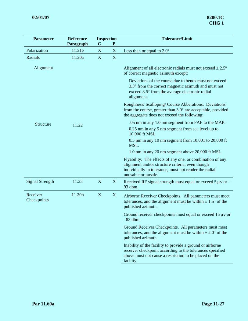
02/01/07 8200.1C CHG 1
Par 11.60a Page 11-27
Parameter Reference Inspection Tolerance/Limit
Paragraph C P
Polarization 11.21e X X Less than or equal to 2.0 Radials
Alignment
Structure
11.20a
11.22
X X Alignment of all electronic radials must not exceed 2.5 of correct magnetic azimuth except:
Deviations of the course due to bends must not exceed 3.5 from the correct magnetic azimuth and must not exceed 3.5 from the average electronic radial alignment.
Roughness/ Scalloping/ Course Abberations: Deviations from the course, greater than 3.0 are acceptable, provided the aggregate does not exceed the following:
.05 nm in any 1.0 nm segment from FAF to the MAP.
0.25 nm in any 5 nm segment from sea level up to 10,000 ft MSL.
0.5 nm in any 10 nm segment from 10,001 to 20,000 ft MSL.
1.0 nm in any 20 nm segment above 20,000 ft MSL.
Flyability: The effects of any one, or combination of any alignment and/or structure criteria, even though individually in tolerance, must not render the radial unusable or unsafe.
Signal Strength 11.23 X X Received RF signal strength must equal or exceed 5 v or –93 dbm.
Receiver Checkpoints
11.20h X X Airborne Receiver Checkpoints. All parameters must meet tolerances, and the alignment must be within 1.5 of the published azimuth.
Ground receiver checkpoints must equal or exceed 15 v or –83 dbm.
Ground Receiver Checkpoints. All parameters must meet tolerances, and the alignment must be within 2.0 of the published azimuth.
Inability of the facility to provide a ground or airborne receiver checkpoint according to the tolerances specified above must not cause a restriction to be placed on the facility.
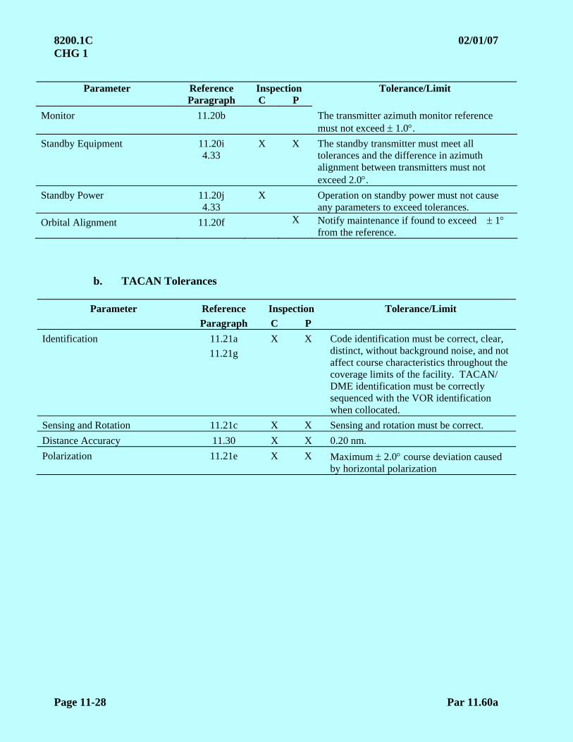
8200.1C 02/01/07 CHG 1
Page 11-28 Par 11.60a
Parameter Reference Inspection Tolerance/Limit
Paragraph C P
Monitor 11.20b The transmitter azimuth monitor reference must not exceed 1.0.
Standby Equipment 11.20i 4.33
X X The standby transmitter must meet all tolerances and the difference in azimuth alignment between transmitters must not exceed 2.0.
Standby Power 11.20j 4.33
X Operation on standby power must not cause any parameters to exceed tolerances.
Orbital Alignment 11.20f X Notify maintenance if found to exceed 1 from the reference.
b. TACAN Tolerances
Parameter Reference Inspection Tolerance/Limit
Paragraph C P
Identification 11.21a
11.21g
X X Code identification must be correct, clear, distinct, without background noise, and not affect course characteristics throughout the coverage limits of the facility. TACAN/ DME identification must be correctly sequenced with the VOR identification when collocated.
Sensing and Rotation 11.21c X X Sensing and rotation must be correct.
Distance Accuracy 11.30 X X 0.20 nm.
Polarization 11.21e X X Maximum 2.0 course deviation caused by horizontal polarization
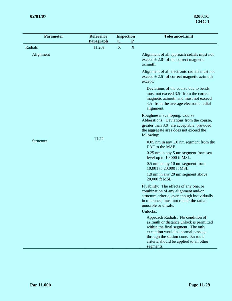
02/01/07 8200.1C CHG 1
Par 11.60b Page 11-29
Parameter Reference Inspection Tolerance/Limit
Paragraph C P
Radials
Alignment Structure
11.20a
11.22
X X
Alignment of all approach radials must not exceed 2.0 of the correct magnetic azimuth.
Alignment of all electronic radials must not exceed 2.5 of correct magnetic azimuth except:
Deviations of the course due to bends must not exceed 3.5 from the correct magnetic azimuth and must not exceed 3.5 from the average electronic radial alignment.
Roughness/ Scalloping/ Course Abberations: Deviations from the course, greater than 3.0 are acceptable, provided the aggregate area does not exceed the following:
0.05 nm in any 1.0 nm segment from the FAF to the MAP.
0.25 nm in any 5 nm segment from sea level up to 10,000 ft MSL.
0.5 nm in any 10 nm segment from 10,001 to 20,000 ft MSL.
1.0 nm in any 20 nm segment above 20,000 ft MSL.
Flyability: The effects of any one, or combination of any alignment and/or structure criteria, even though individually in tolerance, must not render the radial unusable or unsafe.
Unlocks:
Approach Radials: No condition of azimuth or distance unlock is permitted within the final segment. The only exception would be normal passage through the station cone. En route criteria should be applied to all other segments.
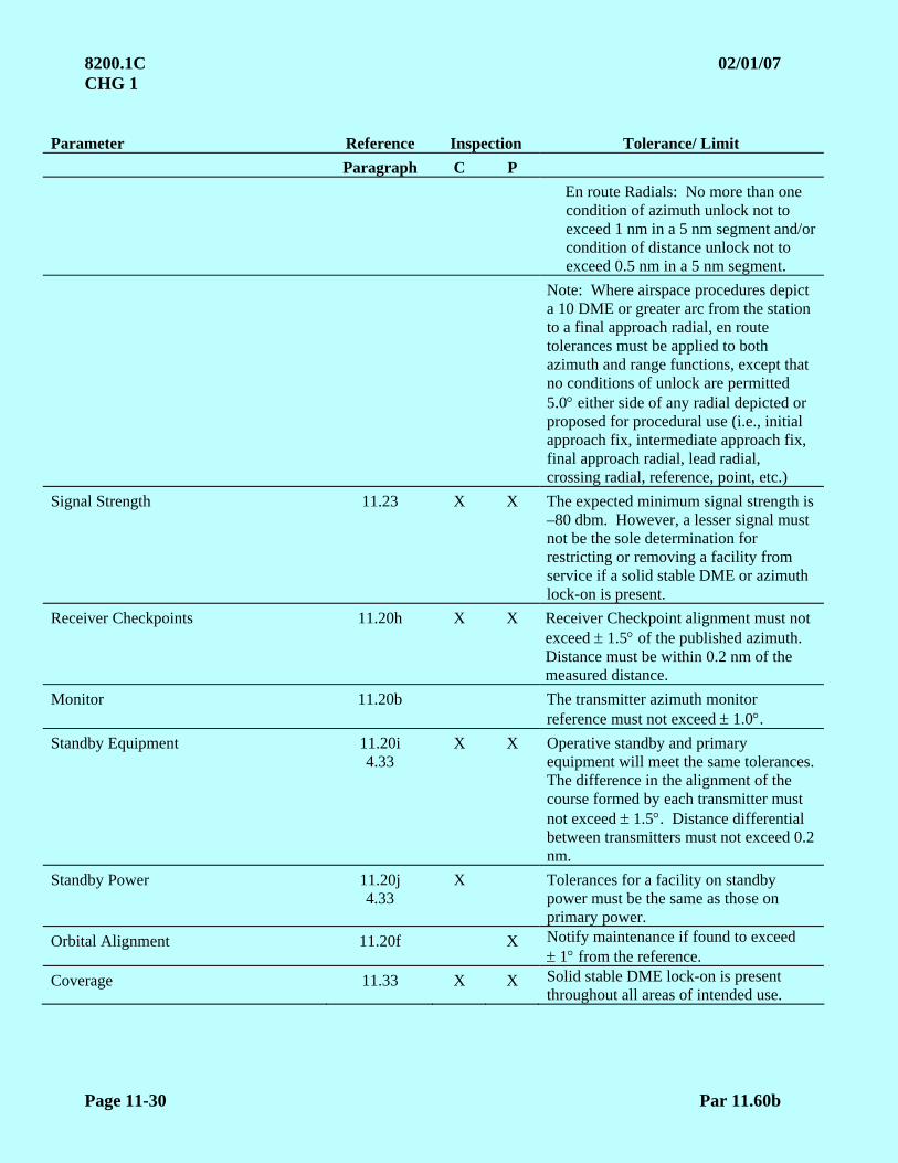
8200.1C 02/01/07 CHG 1
Page 11-30 Par 11.60b
Parameter Reference Inspection Tolerance/ Limit
Paragraph C P
En route Radials: No more than one condition of azimuth unlock not to exceed 1 nm in a 5 nm segment and/or condition of distance unlock not to exceed 0.5 nm in a 5 nm segment.
Note: Where airspace procedures depict a 10 DME or greater arc from the station to a final approach radial, en route tolerances must be applied to both azimuth and range functions, except that no conditions of unlock are permitted 5.0 either side of any radial depicted or proposed for procedural use (i.e., initial approach fix, intermediate approach fix, final approach radial, lead radial, crossing radial, reference, point, etc.)
Signal Strength 11.23 X X The expected minimum signal strength is –80 dbm. However, a lesser signal must not be the sole determination for restricting or removing a facility from service if a solid stable DME or azimuth lock-on is present.
Receiver Checkpoints 11.20h X X Receiver Checkpoint alignment must not exceed 1.5 of the published azimuth. Distance must be within 0.2 nm of the measured distance.
Monitor 11.20b The transmitter azimuth monitor reference must not exceed 1.0.
Standby Equipment 11.20i 4.33
X X Operative standby and primary equipment will meet the same tolerances. The difference in the alignment of the course formed by each transmitter must not exceed 1.5. Distance differential between transmitters must not exceed 0.2 nm.
Standby Power 11.20j 4.33
X Tolerances for a facility on standby power must be the same as those on primary power.
Orbital Alignment 11.20f X Notify maintenance if found to exceed 1 from the reference.
Coverage 11.33 X X Solid stable DME lock-on is present throughout all areas of intended use.

02/01/07 8200.1C CHG 1
Par 11.60c Page 11-31
c. DME Tolerances
Parameter Reference Inspection Tolerance/Limit
Paragraph C P
Identification 11.32 X X Morse code and voice identification must be correct, clear, and identifiable. The audio levels of code and voice must sound similar. The course structure must not be affected by the identification.
Signal Strength 11.23 X X The expected minimum signal strength is –80 dbm. However, a lesser signal must not be the sole determination for restricting or removing a facility from service if a solid stable DME lock-on is present.
Distance Accuracy 11.31 X X 0.20 nm.
Receiver Checkpoints 11.20h X X Distance must be within 0.2 nm of the measured distance.
Coverage 11.24
11.33
X X Solid stable DME lock-on is present throughout all areas of intended use.
Unlocks:
Approach Radials: No condition of distance unlock is permitted within the final segment if required procedurally. The only exception would be normal passage through the station cone. En route criteria should be applied to all other segments.
En route Radials: No more than one condition of distance unlock not to exceed 0.5 nm in a 5 nm segment.

8200.1C 9/14/09 Chg 2
Page 11-32 Par 11.60d
d. VOT Tolerances
VOT Ground Use and Area Service
Inspection Parameter Reference Paragraph C P
Tolerance/ Limit
Frequency Interference 11.53a X X Interference must not cause any out-of-tolerance condition.
Identification 11.53b X X Correct, clear, without background noise. Readable throughout area of coverage. Identification must not affect course characteristics.
Sensing 11.53c X X TO with OBS set at 180 FROM with OBS set at 360
Modulation Level 30 Hz AM, 30 Hz FM (3) and 9960
11.53d X X 25 – 35% (optimum 30%)
Alignment 11.53f X X
0.0 1.0 or less
Coverage (1) Ground (Normal use areas)
11.53g
X
X
15 V minimum
VOT Reference Point Air
11.53e X
X
X
X
15 V minimum 15 V minimum throughout those areas/ altitudes approved for use
Monitor 11.53h X (2) The course alignment monitor must alarm when the course shifts exceed 1.0
Standby Power 11.53i 4.33
X Tolerances for a facility on standby power should be the same as those on primary power.
(1) If the aircraft receiver is capable of measuring exact flag alarm current, apply a tolerance of 240 A flag to all “coverage” checks. (2) Maintenance request (3) When the 30 Hz signal is reported as a devitation ratio, the tolerance is 14.8 – 17.2
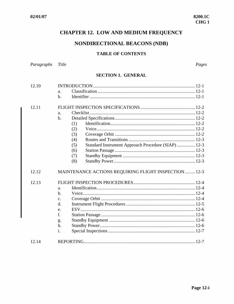
02/01/07 8200.1C CHG 1
Page 12-i
CHAPTER 12. LOW AND MEDIUM FREQUENCY
NONDIRECTIONAL BEACONS (NDB)
TABLE OF CONTENTS Paragraphs Title Pages
SECTION 1. GENERAL
12.10 INTRODUCTION.........................................................................................12-1
a. Classification .....................................................................................12-1 b. Identifier ............................................................................................12-1
12.11 FLIGHT INSPECTION SPECIFICATIONS................................................12-2
a. Checklist ............................................................................................12-2 b. Detailed Specifications......................................................................12-2
(1) Identification..........................................................................12-2 (2) Voice......................................................................................12-2 (3) Coverage Orbit ......................................................................12-2 (4) Routes and Transitions ..........................................................12-3 (5) Standard Instrument Approach Procedure (SIAP) ................12-3 (6) Station Passage ......................................................................12-3 (7) Standby Equipment ...............................................................12-3 (8) Standby Power.......................................................................12-3
12.12 MAINTENANCE ACTIONS REQUIRING FLIGHT INSPECTION .........12-3 12.13 FLIGHT INSPECTION PROCEDURES......................................................12-4
a. Identification......................................................................................12-4 b. Voice..................................................................................................12-4 c. Coverage Orbit ..................................................................................12-4 d. Instrument Flight Procedures ............................................................12-5 e. ESV....................................................................................................12-6 f. Station Passage ..................................................................................12-6 g. Standby Equipment ...........................................................................12-6 h. Standby Power...................................................................................12-6 i. Special Inspections ............................................................................12-7
12.14 REPORTING.................................................................................................12-7

8200.1C 02/01/07 CHG 1
Page 12-ii
TABLE OF CONTENTS (continued)
Paragraphs Title Pages
SECTION 2. FLIGHT INSPECTION TOLERANCES
12.20 TOLERANCES .............................................................................................12-8 a. Morse Code Identification .................................................................12-8 b. Voice Transmission ...........................................................................12-8 c. Usable Distance .................................................................................12-8 d. NDB Approach ..................................................................................12-8 e. Bearing Tolerance Deviation.............................................................12-8 f. Station Passage ..................................................................................12-8 g. Standby Equipment............................................................................12-8
02/01/07 8200.1C CHG 1
Par 12.10 Page 12-1
CHAPTER 12. LOW AND MEDIUM FREQUENCY
NONDIRECTIONAL BEACONS (NDB)
SECTION 1. GENERAL
12.10 INTRODUCTION. A Nondirectional Beacon (NDB) is a low or medium frequency radio beacon that operates in the frequency range 190 to 1,750 kilohertz (kHz). A radio beacon used in conjunction with an Instrument Landing System marker is called a Compass Locator.
a. Classification. NDB(s) are classified according to their intended use. NDB classifications are:
(1) Compass Locators, including a locator at the outer marker (LOM) and a locator at the middle marker (LMM), standard service volume of 15 nm. These facilities are installed at the marker beacon sites associated with ILS facilities. Output power is 25 watts or less.
NOTE: M and H class beacons can also be used as compass locators, in which case the standard service volume would increase to that class level, i.e., MLOM standard service volume is 25 nm, and a HLOM standard service volume is 50 nm. (2) MH Facility, standard service volume of 25 nm. These facilities are used
for short-range navigational purposes. Authorized output power is 50 watts or less.
(3) H Facility, standard service volume of 50 nm. These facilities are used for medium- to long-range navigation and are located along the airways where needed to provide suitable coverage. Authorized output power is from 50 to 2,000 watts.
(4) HH Facility, standard service volume of 75 nm. These facilities are used for long-range and over-water navigation. Authorized output power is 2,000 watts or more.
b. Identifier. Radio beacons transmit a continuous Morse code identifier. Some facilities have a voice feature. A voice feature may be live from a remote location, transcribed weather, or AWOS/ ASOS. A live voice feature may interrupt the facility identification.
(1) The Morse code identification of all classes of NDB facilities, except compass locators, is repeated 5 to 15 times per minute depending on equipment type. Compass locators are identified in the same manner, except the repetition rate is 7 to 20 times per minute.

8200.1C 02/01/07 CHG 1
Page 12-2 Par 12.10
(2) A three-letter code is used to identify all classes of NDB facilities except compass locators. All radio beacons except the compass locators transmit a continuous three-letter identification code except during voice transmissions.
A two-letter code is used to identify compass locator facilities. The code letters are obtained from the code of the associated ILS. The first two letters of the ILS identification are used to identify the outer compass locator (LOM), and the last two letters of the ILS identification are used to identify the middle compass locator (LMM). 12.11 FLIGHT INSPECTION SPECIFICATIONS:
a. Checklist
Type Check Reference Paragraph
C P (5)
Antenna Change (3)
Frequency Change
Identification 12.11b(1) X X X X Voice 12.11b(2) X X X X Coverage Orbit 12.11b(3) X X X Routes and Transitions 12.11b(4) X (1) (4) (1) SIAP 12.11b(5) X (2) (2) (2) Station Passage 12.11b(6) X X X X Standby Transmitter 12.11b(7) X
Standby Power 12.11b(8) 4.33c(1)
X
FOOTNOTES:
(1) Surveillance only incidental to other required checks.
(2) Final approach segment only.
(3) Required for change in antenna type, or when modifications are made to the antenna or to the ground plane, or a change in antenna current designed to change coverage area.
(4) Fly airways, routes, and transitions and reevaluate associated ESV(s).
(5) During periodic inspections, evaluate coverage on a surveillance basis, including verification of the minimum usable distance listed in Paragraph 12.20c.
b. Detailed Specifications
(1) Identification. Monitor the Identification during the evaluation for clarity and interference throughout the intended service volume.
(2) Voice. When installed, the voice feature enables the NDB to transmit messages such as weather reports and observations. For commissioning inspections, the flight inspector must ensure the facility complies with the tolerances in Paragraph 12.20. Spot check operation during periodic inspections.
(3) Coverage Orbit. Coverage must be evaluated by flying an orbit with the radius equal to the area of intended use as listed in Paragraph 12.20c.

02/01/07 8200.1C CHG 1
Par 12.11 Page 12-3
(4) Routes and Transitions. Coverage at distances greater than the orbit radius will be certified for specific routes or transitions and may be evaluated on one transmitter. For satisfactory performance, the facility must meet the tolerances in Paragraph 12.20.
(5) Standard Instrument Approach Procedure (SIAP). Follow the procedures for inspection of SIAP(s) contained in Chapter 6. Altitudes flown must be the minimum proposed or published for the segment evaluated, except that the final segment must be flown to 100 ft below the lowest published MDA.
(a) Commissioning Inspection of SIAP. Evaluate all segments of the proposed procedure, including any holding patterns. Check for excessive needle oscillation, erroneous reversals giving false impression of station passage, or any other unusual condition.
(b) Periodic Inspection of SIAP. The evaluation may be limited to the final approach segment only.
(6) Station Passage. Evaluate the area over the facility for correct indication of station passage. Needle reversal should occur when the aircraft passes directly over or in very near proximity to the station.
(7) Standby Equipment. At facilities where dual transmitters are installed, the flight inspector must check each for a commissioning inspection.
(8) Standby Power. Refer to Paragraph 4.33c(1). If Paragraph 4.33c indicates the standby power should be checked, all the flight inspection checks should be repeated with the NDB on standby power. 12.12 MAINTENANCE ACTIONS REQUIRING FLIGHT INSPECTION. Activities Requiring a Confirming Flight Inspection:
a. Major changes in local obstructions, buildings, etc., which may affect the signal strength and coverage.
b. Replacing the antenna with a different type antenna. Modifications of the antenna or to the ground plane.
c. Change in the antenna current to increase or decrease the service area.
d. Frequency change.
8200.1C 02/01/07 CHG 1
Page 12-4 Par 12.13
12.13 FLIGHT INSPECTION PROCEDURES. The primary objectives of flight inspection are to determine the coverage and quality of the guidance provided by the NDB system and to check for interference from other stations. These assessments are to be made in all areas where coverage is required and with all operational procedures designed for the NDB, in order to determine the usability of the facility and to ensure that it meets the operational requirements for which it was installed.
a. Identification. The facility identification is evaluated throughout the area of intended use, including any route, airway or transition that may extend beyond the normal service volume. The evaluation should be accomplished during all required checks.
(1) Maneuvering. No specific maneuver instructions.
(2) Analysis. The facility identification is out of tolerance when it is incorrect or not identifiable. The coded characters should be correct, clear, and properly spaced.
(3) Other Considerations. On aircraft so equipped, utilize the “Ident” feature on the ADF audio panel.
b. Voice. The voice feature (if installed) is evaluated within the standard service volume. The evaluation may be accomplished while other required checks are being performed.
(1) Maneuvering. No specific maneuver instructions.
(2) Analysis. The voice feature is out of tolerance if it renders the facility identification not decipherable (except live voice). The voice transmission should be evaluated for quality, modulation and freedom from interference. Record the maximum usable voice range on commissioning for future reference. The voice feature should be clear and recognizable for a minimum of two-thirds the standard service volume range. Notify maintenance anytime the voice reception distance is less than the required range. Facility restrictions are not determined by the voice feature. The voice feature should be removed from service if it adversely affects the facility identification.
(3) Other Considerations. On aircraft so equipped, utilize the “Voice” function on the ADF audio panel.
c. Coverage Orbit. Standard service volume coverage is evaluated by flying orbits at the lowest coverage altitude. Facility Maintenance determines the reduced power output of the facility during coverage checks. At facilities where dual transmitters are installed, facility coverage for maximum useable distance may be evaluated by alternating transmitters. Switch transmitters at least every 30 degrees.
02/01/07 8200.1C CHG 1
Par 12.13 Page 12-5
(1) Maneuvering. Fly an orbit about the facility at the maximum distance specified by the facility classification. The orbit altitude must be 1,500 ft above facility site elevation, or the minimum altitude which will provide 1,000 (2,000 ft in designated mountainous areas) above intervening terrain or obstacles, whichever is higher as determined by map study. Coverage orbits are usually completed counterclockwise, as the ADF navigation needle parks to the right if the signal has an unlock (this is true for mechanical instruments; however, the needle may disappear on electronic displays). Sectors found out of tolerance must be evaluated using orbits at reduced distances or increased altitudes in an attempt to determine facility restrictions. Monitor the facility identification during coverage checks, as the loss of the identifier usually corresponds with the loss of the NDB signal.
(2) Analysis. Evaluate the signal for out of tolerance needle oscillations, weak or garbled identification, and interference throughout the coverage area. If the facility performance does not meet tolerances to the SSV, the facility will have the status of restricted or unusable, and NOTAM action is required. If there is a suspicion the beacon carrier frequency is out of tune (off frequency), have ground maintenance check the transmitted frequency, or evaluate with the onboard spectrum analyzer.
(3) Other Considerations. NDB restrictions must be sectored as bearings from the facility. See Chapter 5 for examples of NDB restrictions.
Recommendation: The number of sectors should be kept to a minimum, and preferably should not exceed two.
d. Instrument Flight Procedures
(1) Maneuvering:
(a) Commissioning or Evaluating Amended Procedures. Fly each new procedural segment that uses a facility bearing at the minimum procedural altitude. Fly final approach segments in the direction of intended use. After the procedure turn or FAF, descend to 100 feet below the minimum descent altitude for the segment. In addition, descend to 100 feet below all step-down fix altitudes inside the FAF. Evaluate holding patterns, airways, routes and transitions along the entire procedure at the minimum procedural altitude(s).
(b) Periodic Inspections. Required coverage evaluations during periodic inspections are limited to surveillance checks of any airways, routes or transitions to the extent the aircraft is maneuvered to position for other required checks, as well as all SIAP final approach segments. For SIAP(s) with a FAF, cross the FAF at the minimum published altitude and descend to at least 100 feet below the minimum descent altitude for that segment. For SIAP(s) without a FAF, fly the final segment from the procedure turn distance at the minimum published procedure turn completion altitude and descend to at least 100 feet below the minimum descent altitude for that segment. In addition, descend to 100 feet below all step-down fix altitudes inside the FAF.

8200.1C 02/01/07 CHG 1
Page 12-6 Par 12.13
(3) Analysis. Evaluate the signal for out of tolerance needle oscillations, weak or garbled identification, and interference.
Recommendation: Where two locators are used as supplements to an ILS, the frequency separation between the carriers of the two should be not less than 15 kHz to ensure correct operation of the radio compass, and preferably not more than 25 kHz in order to permit a quick tuning shift in cases where an aircraft has only one radio compass.
e. ESV. For ESV(s), refer to Chapter 22. Coverage at greater than the orbital distance for specific fixes, airways, routes or transitions, may be evaluated on one transmitter. Establish at normal power.
f. Station Passage. Needle reversal should occur when the aircraft passes directly over, or in very close proximity to the facility.
(1) Maneuvering. Overfly the antenna at the minimum procedural altitude.
(2) Analysis. Station passage is out of tolerance if any indication of false station passage occurs, or if station passage does not occur over the station. Momentary needle hunting while near or over the station does not in itself constitute false station passage.
g. Standby Equipment. If dual transmitters are installed, evaluate all required parameters for each transmitter during a commissioning inspection. When practical, for periodic inspections of dual transmitter facilities, conduct the inspection using the transmitter not checked during the previous periodic inspection.
(1) Maneuvering. No specific maneuver instructions.
(2) Analysis. Evaluate the same as primary equipment.
(3) Other Considerations. See Chapter 5 for standby equipment NOTAM.
h. Standby Power. If standby power is installed and of such a type that Paragraph 4.33 requires it be checked, have the facility power source switched to the standby source and repeat all the flight inspection checks (one transmitter only).
(1) Maneuvering. No specific maneuver instructions.
(2) Analysis. Evaluate the signal for out of tolerance needle oscillations, weak or garbled identification, and interference within the coverage area.
(3) Other considerations. Standby power checks are not required for facilities powered by batteries that are constantly charged by another power source. The Facility Data Sheet should indicate the source of standby power.
02/01/07 8200.1C CHG 1
Par 12.13 Page 12-7
i. Special Inspections.
(1) Antenna Change. A special inspection will be conducted when an antenna is replaced with a new type, or modifications are made to the antenna or to the ground plane, or there is a change in antenna current designed to change the coverage area. Evaluate coverage by flying a coverage orbit and the final segments of any SIAP(s). Fly any airways, routes, or transitions and re-evaluate any associated ESV(s). There is no requirement to conduct any checks on standby power or to check the standby transmitter if it is a dual transmitter facility.
(2) Transmitter Change. A flight inspection is not required if the transmitter equipment is replaced, provided ground maintenance can match the established antenna current reference. If ground maintenance does request a flight inspection, follow the antenna change checklist requirements.
(3) Frequency Change. A special inspection will be conducted when a frequency change is made to the facility. Evaluate coverage by flying a coverage orbit and the final segments of any SIAP(s). A surveillance check of any airways, routes, or transitions should be made incidental to aircraft maneuvering to position for other required checks. There is no requirement to reevaluate ESV(s), or conduct any checks on standby power or to check the standby transmitter if it is a dual transmitter facility. 12.14 REPORTING. Reference Order VN200 8240.4, Daily Flight Log (DFL), FAA Form 4040-5, and FAA Order 8240.36, Flight Inspection Report Processing System.
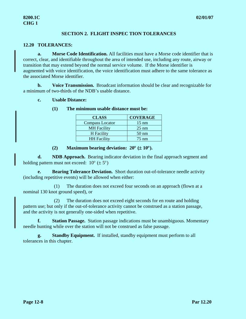
8200.1C 02/01/07 CHG 1
Page 12-8 Par 12.20
SECTION 2. FLIGHT INSPEC TION TOLERANCES 12.20 TOLERANCES:
a. Morse Code Identification. All facilities must have a Morse code identifier that is correct, clear, and identifiable throughout the area of intended use, including any route, airway or transition that may extend beyond the normal service volume. If the Morse identifier is augmented with voice identification, the voice identification must adhere to the same tolerance as the associated Morse identifier.
b. Voice Transmission. Broadcast information should be clear and recognizable for a minimum of two-thirds of the NDB’s usable distance.
c. Usable Distance:
(1) The minimum usable distance must be:
CLASS COVERAGE Compass Locator 15 nm
MH Facility 25 nm H Facility 50 nm
HH Facility 75 nm
(2) Maximum bearing deviation: 20 ( 10).
d. NDB Approach. Bearing indicator deviation in the final approach segment and holding pattern must not exceed: 10 ( 5)
e. Bearing Tolerance Deviation. Short duration out-of-tolerance needle activity (including repetitive events) will be allowed when either:
(1) The duration does not exceed four seconds on an approach (flown at a nominal 130 knot ground speed), or
(2) The duration does not exceed eight seconds for en route and holding pattern use; but only if the out-of-tolerance activity cannot be construed as a station passage, and the activity is not generally one-sided when repetitive.
f. Station Passage. Station passage indications must be unambiguous. Momentary needle hunting while over the station will not be construed as false passage.
g. Standby Equipment. If installed, standby equipment must perform to all tolerances in this chapter.
5/30/11 8200.1C Chg 4
Page 13-i
CHAPTER 13. AREA NAVIGATION (RNAV)
TABLE OF CONTENTS
Paragraphs Title Pages
SECTION 1. AREA NAVIGATION (RNAV) 13.10 INTRODUCTION.............................................................................13-1 13.11 PREFLIGHT REQUIREMENTS......................................................13-2
a. Aircraft ..................................................................................13-2 b. Navigation Database..............................................................13-2 c. Pilot-Defined Procedure ........................................................13-2 d. Evaluation of Procedure Data................................................13-3 e. Navigation System Status......................................................13-3
13.12 FLIGHT INSPECTION PROCEDURES..........................................13-3
a. Checklist ................................................................................13-4 b. Detailed Procedures...............................................................13-4 c. Aircraft Positioning ...............................................................13-5
13.13 FLIGHT INSPECTION ANALYSIS................................................13-6 13.14 TOLERANCES .................................................................................13-7 13.15 ADJUSTMENTS...............................................................................13-7 13.16 DOCUMENTATION ........................................................................13-7
SECTION 2. REQUIRED NAVIGATION PERFORMANCE (RNP) RNAV
13.20 INTRODUCTION.............................................................................13-8 13.21 FLIGHT INSPECTION PROCEDURES..........................................13-8
8200.1C 5/30/11 Chg 4
Page 13-ii
Paragraphs Title Pages
SECTION 3. DME/ DME-SUPPORTED RNAV 13.30 INTRODUCTION.............................................................................................13-9 13.31 PREFLIGHT REQUIREMENTS .....................................................................13-9
a. DME Screening..................................................................................13-9 b. Data Collection ..................................................................................13-9
13.32 AIRCRAFT POSITIONING...........................................................................13-10 a. RNAV Departure Procedure (DP)/
Standard Instrument Departure (SID) ................................................13-10 b. Routes ..............................................................................................13-10 c. RNAV Standard Terminal Arrivals ...................................................13-11 d. Approach............................................................................................13-11 e. Missed Approach ...............................................................................13-11 f. Single Waypoints ...............................................................................13-11
13.33 ANALYSIS.....................................................................................................13-12 13.34 TOLERANCES...............................................................................................13-12
SECTION 4. RNAV WIDE AREA AUGMENTATION SYSTEM (WAAS)
13.40 INTRODUCTION...........................................................................................13-13 13.41 PREFLIGHT REQUIREMENTS ...................................................................13-14
a. LPV FAS Data Block Verification ....................................................13-14 b. WAAS Status .....................................................................................13-14
13.42 FLIGHT INSPECTION PROCEDURES .......................................................13-14
a. Checklist ............................................................................................13-14 b. Detailed Procedures ...........................................................................13-15 c. Aircraft Positioning............................................................................13-15
13.43 FLIGHT INSPECTION ANALYSIS..............................................................13-16
a. CRC Remainder .................................................................................13-16 b. WAAS Signal.....................................................................................13-16 c. Parameters..........................................................................................13-16
13.44 TOLERANCES...............................................................................................13-17
Tables Table 13-1 GPS WAAS Parameters ..................................................................................13-16 Table 13-2 Flight Inspection System (FIS) Announced Data for LPV .............................13-17 Table 13-3 FIS Announced Data
(WAAS Support LNAV/ VNAV without FAS Data) .....................................13-18
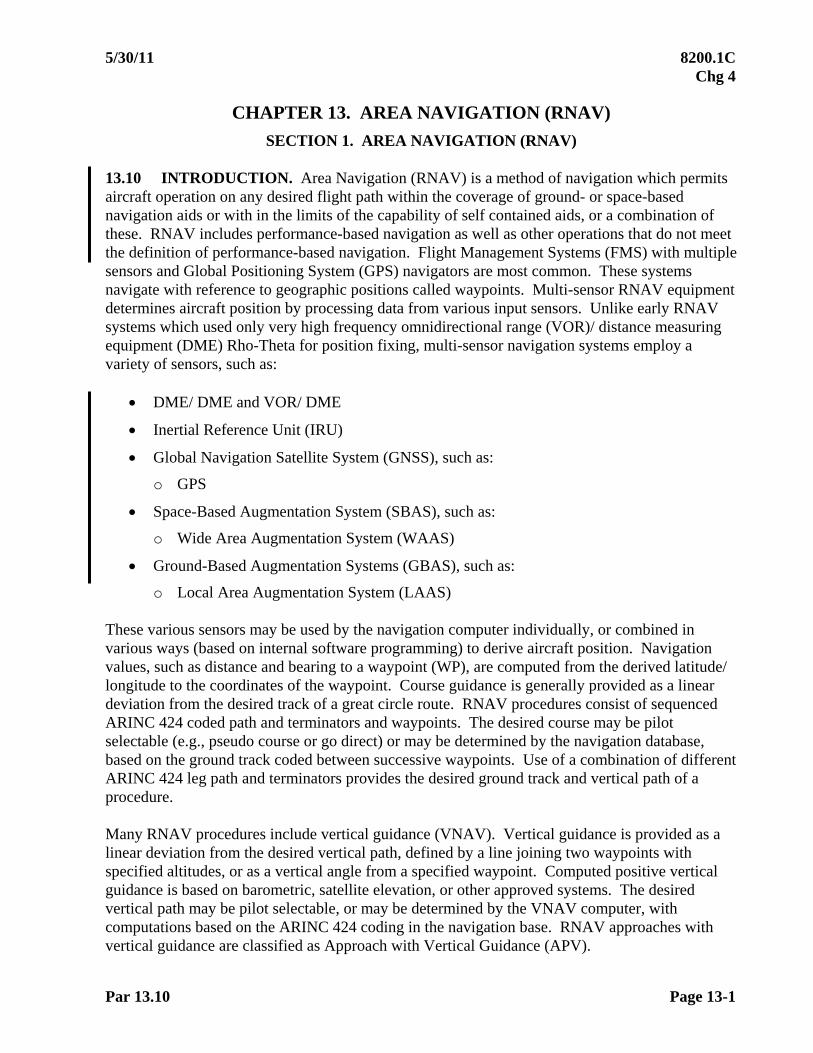
5/30/11 8200.1C Chg 4
Par 13.10 Page 13-1
CHAPTER 13. AREA NAVIGATION (RNAV)
SECTION 1. AREA NAVIGATION (RNAV) 13.10 INTRODUCTION. Area Navigation (RNAV) is a method of navigation which permits aircraft operation on any desired flight path within the coverage of ground- or space-based navigation aids or with in the limits of the capability of self contained aids, or a combination of these. RNAV includes performance-based navigation as well as other operations that do not meet the definition of performance-based navigation. Flight Management Systems (FMS) with multiple sensors and Global Positioning System (GPS) navigators are most common. These systems navigate with reference to geographic positions called waypoints. Multi-sensor RNAV equipment determines aircraft position by processing data from various input sensors. Unlike early RNAV systems which used only very high frequency omnidirectional range (VOR)/ distance measuring equipment (DME) Rho-Theta for position fixing, multi-sensor navigation systems employ a variety of sensors, such as:
DME/ DME and VOR/ DME
Inertial Reference Unit (IRU)
Global Navigation Satellite System (GNSS), such as:
o GPS
Space-Based Augmentation System (SBAS), such as:
o Wide Area Augmentation System (WAAS)
Ground-Based Augmentation Systems (GBAS), such as:
o Local Area Augmentation System (LAAS) These various sensors may be used by the navigation computer individually, or combined in various ways (based on internal software programming) to derive aircraft position. Navigation values, such as distance and bearing to a waypoint (WP), are computed from the derived latitude/ longitude to the coordinates of the waypoint. Course guidance is generally provided as a linear deviation from the desired track of a great circle route. RNAV procedures consist of sequenced ARINC 424 coded path and terminators and waypoints. The desired course may be pilot selectable (e.g., pseudo course or go direct) or may be determined by the navigation database, based on the ground track coded between successive waypoints. Use of a combination of different ARINC 424 leg path and terminators provides the desired ground track and vertical path of a procedure. Many RNAV procedures include vertical guidance (VNAV). Vertical guidance is provided as a linear deviation from the desired vertical path, defined by a line joining two waypoints with specified altitudes, or as a vertical angle from a specified waypoint. Computed positive vertical guidance is based on barometric, satellite elevation, or other approved systems. The desired vertical path may be pilot selectable, or may be determined by the VNAV computer, with computations based on the ARINC 424 coding in the navigation base. RNAV approaches with vertical guidance are classified as Approach with Vertical Guidance (APV).

8200.1C 5/30/11 Chg 4
Page 13-2 Par 13.11
13.11 PREFLIGHT REQUIREMENTS
a. Aircraft. The aircraft avionics configuration must be appropriate to support the procedure to be flight inspected. Flight Inspection of RNAV Standard Instrument Departure (SID(s)), airways, and Standard Terminal Arrival Route (STAR(s)) may be accomplished with any flight inspection aircraft capable of the procedure’s ARINC 424 path and terminators. RNAV approach charts provide separate minima for Lateral Navigation (LNAV), Lateral and Vertical Navigation (LNAV/ VNAV), and LPV. Inspection of an RNAV procedure with vertical guidance requires an appropriately equipped flight inspection aircraft. Flight inspection of an LNAV approach procedure (without vertical navigation) may be accomplished with any flight inspection aircraft capable of the procedure’s ARINC 424 path and terminators.
b. Navigation Database. Verify a current navigation database is installed. Use waypoint data from the FMS/ GPS navigation database when available. When official government source ARINC 424 navigation data is available, it must be used for the flight inspection.
c. Pilot-Defined Procedure. RNAV procedures (databases) are designed (coded) using ARINC 424 path and terminators. Path and terminator combinations can result in different ground tracks; hence, requiring utmost compliance with the official government source documentation. Entering the RNAV procedure simply as a route does not adequately represent the ARINC 424 leg types used to define the procedure or provide for the intended ground track on which obstacle clearance and other requirements are based. A difference in the ARINC 424 coded data from the source documentation can result in very different FMS/ GPS performance and aircraft ground and vertical track.
(1) Waypoint resolution is critical. For approach procedures with vertical guidance and minimums, enter latitude/ longitude to a minimum of thousandths (1/ 1,000) of a minute.
(2) For vertically guided approaches, enter waypoint altitudes as depicted. The end-of-approach (EOA) waypoint altitude at the threshold should be the actual runway threshold MSL altitude, plus the proposed TCH. For offset approach procedures, the end-of-approach (EOA) altitude is found by calculating the altitude at which the glide path angle (GPA) passes through the EOA waypoint.

5/30/11 8200.1C Chg 4
Par 13.11d Page 13-3
d. Evaluation of Procedure Data. Prior to the procedure being flown, leg segment data accuracy must be evaluated by comparison of the procedural waypoint data (FAA Form 8260 or equivalent) to the flight plan waypoint data. Use the official source documentation to obtain the ARINC 424 coding.
Verify true course to next waypoint, distances, and the Flight Path Angle (FPA) indicated on the FMS or GPS accurately reflects the procedure design.
When evaluating RNAV CF legs, including holding legs (HM, HF, HA), compare aircraft navigation performance with the instrument procedure design. Do not apply any tolerance to course-to-fix values. Confirmation of proper ARINC coding will be accomplished with either an appropriately equipped aircraft, or by a desktop evaluation of the current navigation database.
Out-of-tolerance values must be resolved with the procedure designer.
e. Navigation System Status. Determine the status of the required navigation system(s) (e.g., DME, GPS, LAAS, and WAAS) before every flight inspection and after an inspection that detects anomalies. NOTAM(s) and GPS Service Interruptions (interference testing) location and schedule should be considered. 13.12 FLIGHT INSPECTION PROCEDURES. The RNAV procedure must be inspected IAW Chapter 6 and appropriate sections of this chapter. The flight inspection of RNAV procedures will evaluate safety, flyability, human factors, navigation data, and workload. Any anomalies found during inspection must be resolved before the procedure is approved. Use appropriate FAA Order(s) or approved guidance for required obstruction clearance criteria such as:
FAA Order 8260.44, Civil Utilization of RNAV Departure Procedures
FAA Order 8260.54, The United States Standard for Area Navigation (RNAV)
FAA Order 8260.52, US Standard for RNP Approach Procedures with Special Aircraft and Aircrew Authorization Required
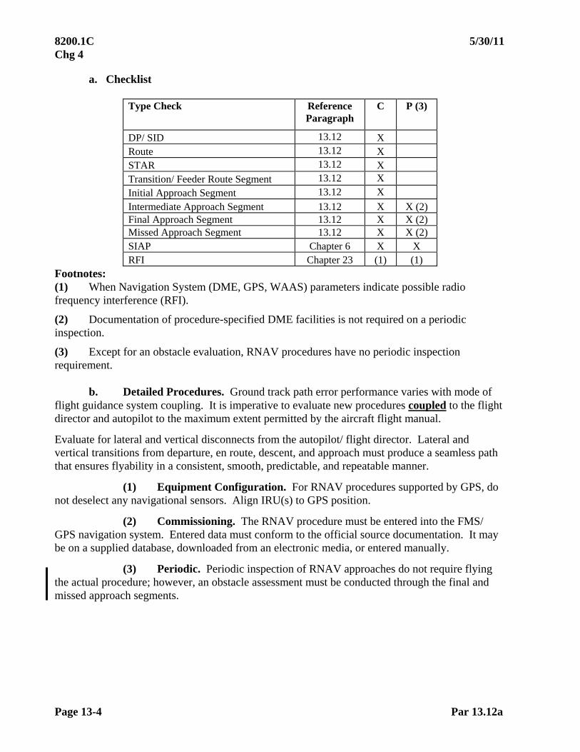
8200.1C 5/30/11 Chg 4
Page 13-4 Par 13.12a
a. Checklist
Type Check Reference Paragraph
C P (3)
DP/ SID 13.12 X Route 13.12 X STAR 13.12 X Transition/ Feeder Route Segment 13.12 X
Initial Approach Segment 13.12 X
Intermediate Approach Segment 13.12 X X (2) Final Approach Segment 13.12 X X (2) Missed Approach Segment 13.12 X X (2) SIAP Chapter 6 X X RFI Chapter 23 (1) (1)
Footnotes: (1) When Navigation System (DME, GPS, WAAS) parameters indicate possible radio frequency interference (RFI).
(2) Documentation of procedure-specified DME facilities is not required on a periodic inspection.
(3) Except for an obstacle evaluation, RNAV procedures have no periodic inspection requirement.
b. Detailed Procedures. Ground track path error performance varies with mode of flight guidance system coupling. It is imperative to evaluate new procedures coupled to the flight director and autopilot to the maximum extent permitted by the aircraft flight manual.
Evaluate for lateral and vertical disconnects from the autopilot/ flight director. Lateral and vertical transitions from departure, en route, descent, and approach must produce a seamless path that ensures flyability in a consistent, smooth, predictable, and repeatable manner.
(1) Equipment Configuration. For RNAV procedures supported by GPS, do not deselect any navigational sensors. Align IRU(s) to GPS position.
(2) Commissioning. The RNAV procedure must be entered into the FMS/ GPS navigation system. Entered data must conform to the official source documentation. It may be on a supplied database, downloaded from an electronic media, or entered manually.
(3) Periodic. Periodic inspection of RNAV approaches do not require flying the actual procedure; however, an obstacle assessment must be conducted through the final and missed approach segments.
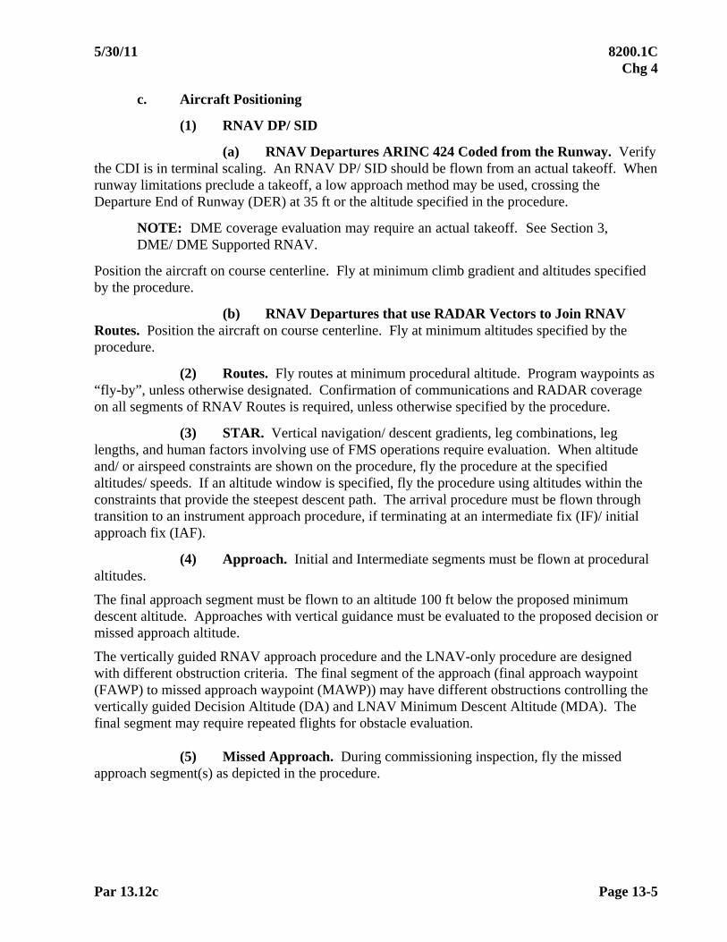
5/30/11 8200.1C Chg 4
Par 13.12c Page 13-5
c. Aircraft Positioning
(1) RNAV DP/ SID
(a) RNAV Departures ARINC 424 Coded from the Runway. Verify the CDI is in terminal scaling. An RNAV DP/ SID should be flown from an actual takeoff. When runway limitations preclude a takeoff, a low approach method may be used, crossing the Departure End of Runway (DER) at 35 ft or the altitude specified in the procedure.
NOTE: DME coverage evaluation may require an actual takeoff. See Section 3, DME/ DME Supported RNAV.
Position the aircraft on course centerline. Fly at minimum climb gradient and altitudes specified by the procedure.
(b) RNAV Departures that use RADAR Vectors to Join RNAV Routes. Position the aircraft on course centerline. Fly at minimum altitudes specified by the procedure.
(2) Routes. Fly routes at minimum procedural altitude. Program waypoints as “fly-by”, unless otherwise designated. Confirmation of communications and RADAR coverage on all segments of RNAV Routes is required, unless otherwise specified by the procedure.
(3) STAR. Vertical navigation/ descent gradients, leg combinations, leg lengths, and human factors involving use of FMS operations require evaluation. When altitude and/ or airspeed constraints are shown on the procedure, fly the procedure at the specified altitudes/ speeds. If an altitude window is specified, fly the procedure using altitudes within the constraints that provide the steepest descent path. The arrival procedure must be flown through transition to an instrument approach procedure, if terminating at an intermediate fix (IF)/ initial approach fix (IAF).
(4) Approach. Initial and Intermediate segments must be flown at procedural altitudes.
The final approach segment must be flown to an altitude 100 ft below the proposed minimum descent altitude. Approaches with vertical guidance must be evaluated to the proposed decision or missed approach altitude.
The vertically guided RNAV approach procedure and the LNAV-only procedure are designed with different obstruction criteria. The final segment of the approach (final approach waypoint (FAWP) to missed approach waypoint (MAWP)) may have different obstructions controlling the vertically guided Decision Altitude (DA) and LNAV Minimum Descent Altitude (MDA). The final segment may require repeated flights for obstacle evaluation.
(5) Missed Approach. During commissioning inspection, fly the missed approach segment(s) as depicted in the procedure.

8200.1C 5/30/11 Chg 4
Page 13-6 Par 13.13
13.13 FLIGHT INSPECTION ANALYSIS. Flight inspection of RNAV procedures determines if the procedure is flyable, safe, and navigation data is correct. ARINC 424 coded data will be used to compare coded path versus actual path to verify all data prior to release to the public and other database suppliers. If a new procedure is unsatisfactory, the flight inspector must coordinate with the procedures designer, ATC, and/ or the proponent of the procedure, as applicable, to determine the necessary changes. When existing procedures are found unsatisfactory, notify the procedures designer immediately for Notice to Airman (NOTAM) action. The inspector must evaluate the following items:
a. Waypoint spacing is sufficient to allow the aircraft to stabilize on each leg segment without jumping over waypoints/ legs. Leg length must be sufficient to allow for aircraft deceleration or altitude change, if required.
b. Procedural Design. The procedure must be evaluated to verify the geodetic coordinates (waypoints) and vertical path angles meet the requirements of Paragraph 13.14.
c. GPS Parameters. The following parameters must be documented at the time anomalies are found during any phase of the flight inspection. Forward recorded data to flight inspection policy for analysis.
Parameter Expected Value HDOPGPS 1.0 – 4.0 VDOPGPS 1.0 – 4.0 HILGPS 0.3 or less HFOM 22 meters Satellites Tracked 5 minimum Signal-to-Noise Ratio (SNR) 30 dB/ Hz minimum
There are no flight inspection tolerances applied to these parameters. However, the values listed above provide a baseline for analysis of system signal anomalies or interference encountered.
d. Interference. The RF spectrum from 1,155 to 1,250 MHz and 1,555 to 1,595 MHz should be observed when GPS parameters indicate possible RF interference. Interfering signals are not restrictive, unless they affect the receiver/ sensor performance. The SNR values being recorded may indicate RF interference problems. The normal GPS signal strength is –130 to –123 dBm. Use the SNR values, along with the spectrum analyzer, to investigate the RF interference, the location of its occurrence, and possible sources. Particular attention must be given to harmonics on or within 20 MHz of GPS L1 (1,575.42 MHz), L5 (1,176.45 MHz), and those on or within 10 MHz of GPS L2 (1,227.6 MHz).
During an RNAV procedure, document all spectrum anomalies. Paper records and electronic collection of data are required.
NOTE: Report interference to the FICO, who will in turn forward the report to the ATCSCC/ Spectrum Assignment and Engineering Office at Herndon, Virginia.
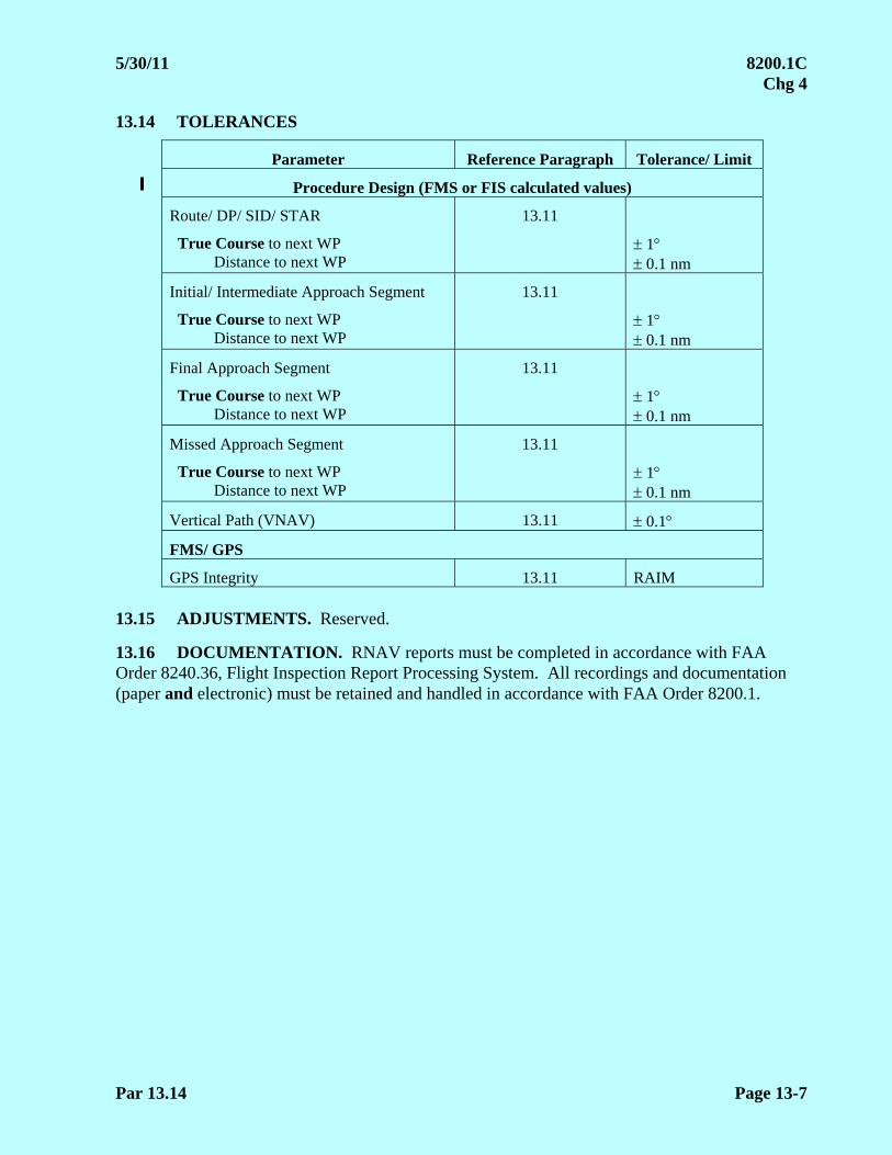
5/30/11 8200.1C Chg 4
Par 13.14 Page 13-7
13.14 TOLERANCES
Parameter Reference Paragraph Tolerance/ Limit
Procedure Design (FMS or FIS calculated values)
Route/ DP/ SID/ STAR
True Course to next WP Distance to next WP
13.11
1 0.1 nm
Initial/ Intermediate Approach Segment
True Course to next WP Distance to next WP
13.11
1 0.1 nm
Final Approach Segment
True Course to next WP Distance to next WP
13.11
1 0.1 nm
Missed Approach Segment
True Course to next WP Distance to next WP
13.11
1 0.1 nm
Vertical Path (VNAV) 13.11 0.1
FMS/ GPS
GPS Integrity 13.11 RAIM 13.15 ADJUSTMENTS. Reserved.
13.16 DOCUMENTATION. RNAV reports must be completed in accordance with FAA Order 8240.36, Flight Inspection Report Processing System. All recordings and documentation (paper and electronic) must be retained and handled in accordance with FAA Order 8200.1.
8200.1C 5/30/11 Chg 4
Page 13-8 Par 13.20
SECTION 2. REQUIRED NAVIGATION PERFORMANCE (RNP) RNAV This section provides additional guidance to Section 1 of this chapter for inspection of RNP RNAV procedures. 13.20 INTRODUCTION. RNP is a statement of the navigation performance accuracy necessary for operation within a defined airspace. RNP is stated as a number in nautical miles. This specifies how tight the avionics must contain Total System Error (TSE). RNP applies to navigation performance and includes the capability of both the available infrastructure (navigation systems) and the aircraft equipment. For example, an aircraft may be equipped and certified for RNP 1.0 but may not be capable of RNP 1.0 operations due to limited NAVAID coverage. RNP levels address obstacle protection associated with RNP accuracy values. The RNP level (RNP x, where x=0.3, 1, 2, etc.), when applied to instrument procedure obstacle evaluation areas, is a variable used to determine a segment primary area half-width value, i.e., total width is a multiple of the value used to identify the level. Parallel lines normally bound obstruction clearance areas associated with RNP. 13.21 FLIGHT INSPECTION PROCEDURES. Inspect RNP RNAV procedures per Section 1 of this chapter. Use appropriate FAA Order(s) or approved criteria (e.g., FAA Order 8260.52, U.S. Standard for RNP Instrument Approach Procedures with Special Aircraft and Aircrew Authorization Required (SAAAR)) for procedure design and required obstruction clearance criteria.
Obstacle Evaluation. When containment area obstacle verification is required, fly a 2xRNP (containment limit) offset each side of centerline (i.e., RNP-0.3 segment, fly a 0.6 nm offset each side of course centerline). Assign altitudes to the offset waypoints as required for the vertical profile. Use the offset to provide situational awareness of obstacles inside the containment boundary, which may affect the procedure integrity.
NOTE: Containment limit obstacle verification is not required on segments which have the obstacle environment surveyed or on segments that obstacles against the RNP containment limit are not a factor. Use extreme caution when flying the containment limit. Obstructions (towers, terrain, etc.) may be against the edge of the containment limit.

5/30/11 8200.1C Chg 4
Par 13.30 Page 13-9
SECTION 3. DISTANCE MEASURING EQUIPMENT (DME) DME/ DME-SUPPORTED RNAV
This section provides supplemental guidance to Section 1 of this chapter for inspection of RNAV procedures requiring a DME/ DME infrastructure. 13.30 INTRODUCTION. For most aircraft with FMS installations which do not have a GPS sensor, DME is used to calculate position. The primary method is to calculate position from the crossing angles of 2 or more DME facilities. The FMS chooses DME facilities which intersect the aircraft between 30 and 150 crossing angle. The optimum pair of DME facilities will have a crossing angle closest to 90. The FMS database is searched every few minutes to choose the most optimum pair of DME facilities. The FMS may have a “Scanning DME” function. This function allows multiple DME facilities to be scanned in a few seconds. The more DME facilities and the more widely they are dispersed, the greater the positioning accuracy. DME positioning may be able to provide a positioning accuracy to 0.1 nm at a location of optimal DME geometry. 13.31 PREFLIGHT REQUIREMENTS. RNAV procedures supported by a DME/ DME infrastructure must be inspected in accordance with Chapter 13, Section 1. Documentation of all identified DME facilities will be accomplished through paper recordings and electronic collection of data (FIS required).
a. DME Screening. A computer-screening model (RNAV-Pro) identifies DME facilities, predicted to possess the accuracy, coverage, and geometry requirements needed to provide a navigation solution to support the procedure. Results are documented to a comma separated value (CSV) file. The CSV file is loaded into FIS for the procedure inspection.
NOTE: RNAV-Pro DME Screening CSV files are direction specific. The appropriate CSV file is required for direction of flight.
Flight inspection will verify DME coverage and accuracy for the FMS-equipped aircraft utilizing a DME sensor for primary navigation positioning.
b. Data Collection. FIS software may allow up to five (5) DME facilities to be monitored and recorded. DME(s) to be checked over a designated area are specified in the RNAV-Pro screening output file.
(1) While the electronic data file will be used to determine coverage, it is important to annotate passage of each waypoint on the paper recording.
(2) Appropriate DME facility changes will be initiated based on the RNAV-Pro output file.

8200.1C 5/30/11 Chg 4
Page 13-10 Par 13.32
13.32 AIRCRAFT POSITIONING. All segments requiring vertical path change must be inspected in the intended direction of flight, using minimum climb gradients and minimum altitudes specified in the procedure package. Position the aircraft on course centerline. Use the Global Navigation Satellite System (GNSS) as the primary navigation sensor for the inspection. During the inspection, if a Critical, or expanded service volume (ESV) designated DME appears not to be transmitting, verify with Air Traffic or a local Flight Service Station that the facility is in service. If a DME designated Critical is off the air, the inspection must be terminated and resumed after the facility is returned to service. When there are three or less DME(s) and one of the three is out of service, the check should be rescheduled.
a. RNAV Departure Procedure/ Standard Instrument Departure (SID). Departures requiring a DME/ DME navigation solution at the earliest possible point from takeoff must be flown from an actual takeoff. Position aircraft IAW Section 1.
(1) Parallel Runways Departing to a Common Route. If parallel runways are separated by 3,400 ft or less, the DME evaluation may be accomplished by departing from either parallel, unless the DME screening identifies runway dependent DME(s).
(2) RNAV Departures that use RADAR Vectors to Join RNAV Routes (RDVA). The Pilot Navigation Area (PNA) is an area used to transition from radar vectoring to the area navigation route. It is defined by two perimeter boundaries and an arc radius referenced from the initial departure fix (IDF). See Figure 13-1. The PNA is developed by the procedures specialist and is specified on FAA Form 8260-15B, Graphic Departure Procedure, as bearings to the IDF with arc radius and minimum altitude. The bearings to the IDF are used as perimeter boundaries. Record DME facility coverage along each perimeter boundary between the IDF and the arc radius distance, either inbound or outbound, at the minimum altitude. Refer to FAA Order 8260.53, Standard Instrument Departures That Use RADAR Vectors to Join RNAV Routes, for procedure development criteria.

5/30/11 8200.1C Chg 4
Par 13.32a Page 13-11
Figure 13-1 SID Overview
b. Routes can be flown in either direction. All routes will be flown on course
centerline at the minimum altitude (true) specified in the procedure package.
c. RNAV Standard Terminal Arrivals. Aircraft positioning is in accordance with Section 1 of this chapter.
d. Approach. Document DME coverage at the procedural (true) altitude(s) for all segments. Fly the Final Approach Segment (FAS), descending on path to 100 ft below the lowest minima.
NOTE: Loss of DME facility coverage in the FAS is expected. The aircraft’s IRU is expected to provide navigation guidance to the MAP and throughout the missed approach segment until a DME/ DME navigation solution is regained.
e. Missed Approach. Aircraft positioning is in accordance with Section 1 of this
chapter.
f. Single Waypoints. DME coverage and accuracy will be verified based on an orbit centered on the waypoint coordinates. The radius of the orbit must be calculated based on the DME station farthest from the waypoint, using the formula contained in Appendix 2, or 3.0 nm, whichever is larger. Document DME coverage at 100 ft below the procedural (true) altitude.
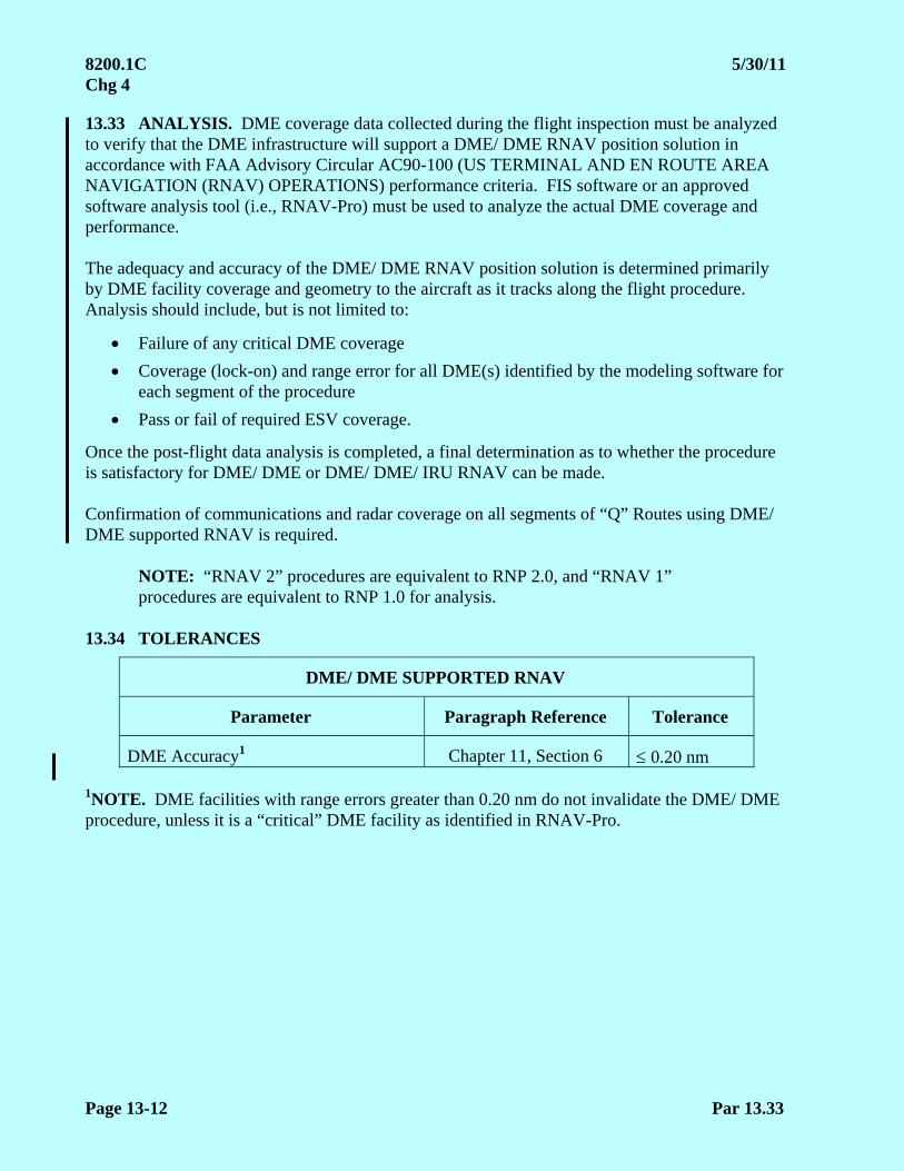
8200.1C 5/30/11 Chg 4
Page 13-12 Par 13.33
13.33 ANALYSIS. DME coverage data collected during the flight inspection must be analyzed to verify that the DME infrastructure will support a DME/ DME RNAV position solution in accordance with FAA Advisory Circular AC90-100 (US TERMINAL AND EN ROUTE AREA NAVIGATION (RNAV) OPERATIONS) performance criteria. FIS software or an approved software analysis tool (i.e., RNAV-Pro) must be used to analyze the actual DME coverage and performance. The adequacy and accuracy of the DME/ DME RNAV position solution is determined primarily by DME facility coverage and geometry to the aircraft as it tracks along the flight procedure. Analysis should include, but is not limited to:
Failure of any critical DME coverage
Coverage (lock-on) and range error for all DME(s) identified by the modeling software for each segment of the procedure
Pass or fail of required ESV coverage.
Once the post-flight data analysis is completed, a final determination as to whether the procedure is satisfactory for DME/ DME or DME/ DME/ IRU RNAV can be made. Confirmation of communications and radar coverage on all segments of “Q” Routes using DME/ DME supported RNAV is required.
NOTE: “RNAV 2” procedures are equivalent to RNP 2.0, and “RNAV 1” procedures are equivalent to RNP 1.0 for analysis.
13.34 TOLERANCES
DME/ DME SUPPORTED RNAV
Parameter Paragraph Reference Tolerance
DME Accuracy1 Chapter 11, Section 6 0.20 nm 1NOTE. DME facilities with range errors greater than 0.20 nm do not invalidate the DME/ DME procedure, unless it is a “critical” DME facility as identified in RNAV-Pro.
5/30/11 8200.1C Chg 4
Par 13.40 Page 13-13
SECTION 4. WIDE AREA AUGMENTATION SYSTEM (WAAS) RNAV This section provides supplemental guidance to Section 1 of this chapter for inspection of RNAV procedures requiring WAAS. 13.40 INTRODUCTION. The WAAS provides augmentation, including integrity broadcasts, differential corrections, and additional ranging signals to the standard GPS signal. It provides the accuracy, integrity, availability, and continuity required to support oceanic, remote-area, en route, terminal, non-precision approach, and APV approach phases of flight. WAAS utilizes a network of wide-area reference stations (WRS) that receive and monitor the GPS signals. Data from these reference stations are transmitted to one of two wide-area master stations (WMS), where the validity of the signals from each satellite is assessed and wide-area corrections are computed. These validity (integrity) messages and wide-area corrections are transmitted to aircraft via Geostationary Earth Orbit (GEO) communications satellites that serve as additional sources of GPS ranging signals, increasing the number of satellites available to the system users. The WAAS signal is transmitted on the same frequency (L1 – 1,575.42 MHz) and with the same type of code-division multiplex modulation as the GPS Standard Positioning Service (SPS) signal. This allows a WAAS receiver to acquire and process both the GPS and WAAS broadcasts. An integrity message transmitted by the WAAS provides the user with a direct verification of the integrity of the signal from each satellite in view. FAA Order 8260.54, The United States Standard for Area Navigation (RNAV), specifies design criteria for approach procedures. Approaches constructed under these criteria are termed “LP” or “LPV”. The lateral protection area is based on precision approach trapezoid dimensions criterion. RNAV WAAS LP procedures can be supported to HAT values 250 feet. LPV procedures can be supported to HAT values 200 feet. In addition to LP/ LPV procedures, WAAS supports LNAV and LNAV/ VNAV approaches. WAAS can be used to support the vertical guidance requirements for RNAV LNAV/ VNAV approach procedures at airports where BARO-VNAV is not authorized. Avionics systems using WAAS for vertical guidance are not limited by approach procedure BARO-VNAV temperature restrictions.

8200.1C 5/30/11 Chg 4
Page 13-14 Par 13.41
13.41 PREFLIGHT REQUIREMENTS
a. LP/ LPV FAS Data Block Verification. The LP/ LPV FAS data (data specified on FAA Form 8260-10) is developed and coded into binary files by the procedure developer. The FAS data files are saved into a network file for flight inspection access. Download the FAS data blocks files required for the scheduled itinerary onto removable disk media.
Prior to mission departure, confirm FIS access to the removable disk media. Access each individual FAS data file and confirm the CRC Remainder matches the FAA Form 8260-10 data. This ensures no errors occurred during data transfer (data file integrity). Any corruption must be resolved prior to conducting the inspection. The FIS uses the FAS data to calculate course alignment, glide path angle, and threshold crossing height.
b. WAAS Status. Determine WAAS status before every flight inspection and after an inspection that detects anomalies. WAAS/ GPS NOTAM(s) and GPS Service Interruptions (interference testing) location and schedule should be considered. Severe solar storm activity may adversely affect WAAS availability for approach.
13.42 FLIGHT INSPECTION PROCEDURES. The RNAV WAAS LP/ LPV procedure must be inspected IAW Chapter 6, Flight Inspection of Instrument Flight Procedures, and this chapter. FAA Order 8260.54, The United States Standard for Area Navigation (RNAV), contains required obstruction clearance criteria.
a. Checklist
Type Check Reference or Paragraph C P (2) DP/ SID Chapter 13, Section 1 X Route Chapter 13, Section 1 X STAR Chapter 13, Section 1 X Transition/ Feeder Route Segment
Chapter 13, Section 1 X
Initial Approach Segment Chapter 13, Section 1 X
Intermediate Approach Segment
Chapter 13, Section 1 X
X
Final Approach Segment
Chapter 13, Section 1
X
X
Missed Approach Segment
Chapter 13, Section 1
X
X
SIAP Chapter 6 X X RFI Chapter 13, Section 1
Chapter 23 (1) (1)
Footnotes:
(1) When GPS/ WAAS parameters indicate possible RFI.
(2) Except for an obstacle evaluation, RNAV LP/ LPV procedures have no periodic inspection requirement.
5/30/11 8200.1C Chg 4
Par 13.42b Page 13-15
b. Detailed Procedures
(1) For RNAV WAAS LP/ LPV, do not deselect any navigation sensors.
(2) Paper recordings and electronic collection of data are required. During an RNAV WAAS LP/ LPV approach, document WAAS data starting from the intermediate waypoint inbound to the Landing Threshold Point (LTP)/ Fictitious Threshold Point (FTP). A flight inspection “low approach” is required to provide back corrections for data analysis. Also, document WAAS data on below-glide-path runs.
c. Aircraft Positioning
(1) Commissioning
(a) The FAS positioning must be on course, on path. Evaluate the Glide Path Angle (GPA) course guidance, WAAS positioning, and delivery alignment throughout the final approach segment.
(b) Confirm WAAS glidepath full scale fly-up.
(2) Periodic. Periodic inspection of RNAV WAAS LP/LPV approaches do not require flying the actual procedure; however, an obstacle assessment must be conducted through the final and missed approach segments.
(3) WAAS Interference. If interference is suspected, record additional data from the two following runs. Evaluation of the final approach segment for interference is accomplished by flying along the left and right edges of primary FAS obstruction trapezoid. (Create a route using 90 offset waypoints 0.3 nm from the PFAF and 0.1 nm from the Missed Approach Waypoint (MAWP), respectively, with a vertical angle at least 1 less than the procedure GPA (full scale fly-up) for LPV or at MDA for LP. This will provide lateral/ vertical guidance slightly outside the “W” obstacle clearance surface.) Assure that a full fly-up indication is provided below the approach GPA on FAS centerline and along edges of the primary FAS obstruction trapezoid.
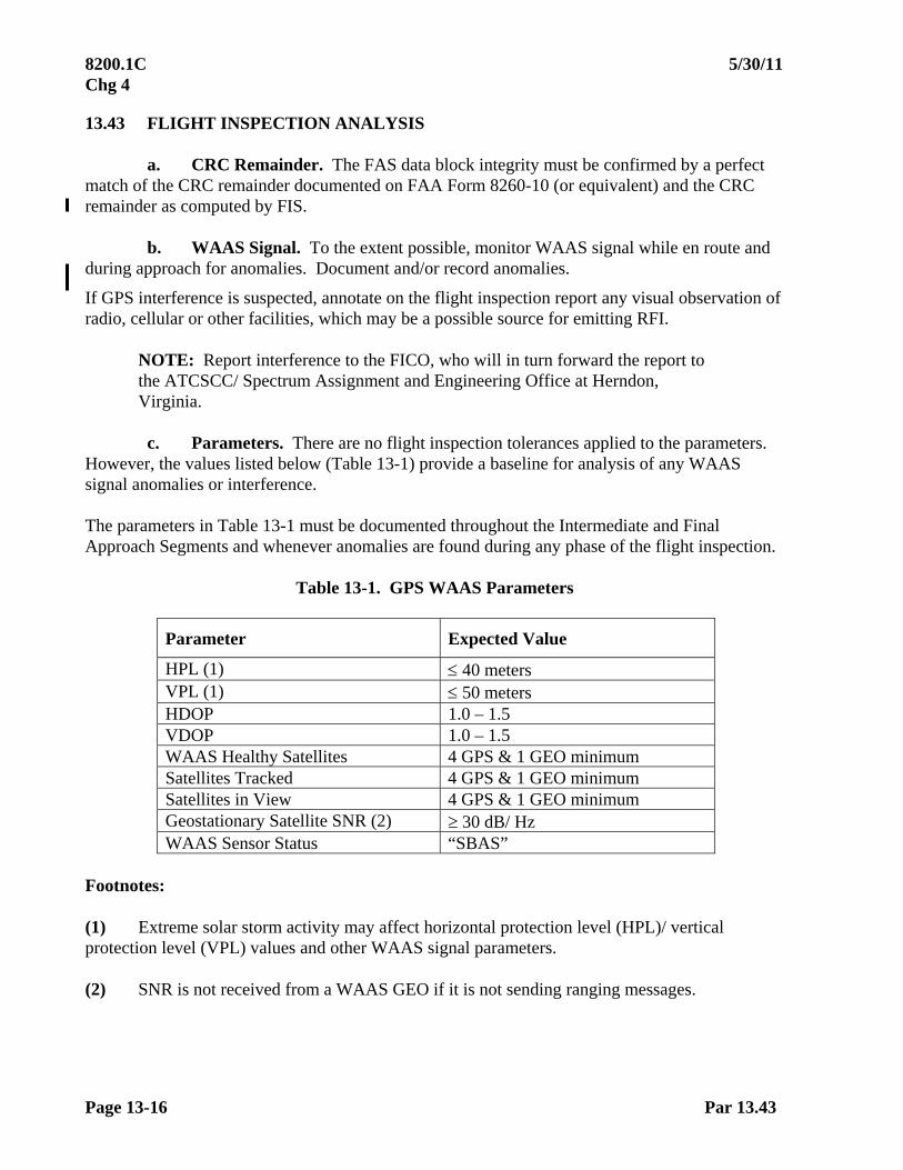
8200.1C 5/30/11 Chg 4
Page 13-16 Par 13.43
13.43 FLIGHT INSPECTION ANALYSIS
a. CRC Remainder. The FAS data block integrity must be confirmed by a perfect match of the CRC remainder documented on FAA Form 8260-10 (or equivalent) and the CRC remainder as computed by FIS.
b. WAAS Signal. To the extent possible, monitor WAAS signal while en route and during approach for anomalies. Document and/or record anomalies.
If GPS interference is suspected, annotate on the flight inspection report any visual observation of radio, cellular or other facilities, which may be a possible source for emitting RFI.
NOTE: Report interference to the FICO, who will in turn forward the report to the ATCSCC/ Spectrum Assignment and Engineering Office at Herndon, Virginia.
c. Parameters. There are no flight inspection tolerances applied to the parameters.
However, the values listed below (Table 13-1) provide a baseline for analysis of any WAAS signal anomalies or interference. The parameters in Table 13-1 must be documented throughout the Intermediate and Final Approach Segments and whenever anomalies are found during any phase of the flight inspection.
Table 13-1. GPS WAAS Parameters
Parameter Expected Value
HPL (1) 40 meters VPL (1) 50 meters HDOP 1.0 – 1.5 VDOP 1.0 – 1.5 WAAS Healthy Satellites 4 GPS & 1 GEO minimum Satellites Tracked 4 GPS & 1 GEO minimum Satellites in View 4 GPS & 1 GEO minimum Geostationary Satellite SNR (2) 30 dB/ Hz WAAS Sensor Status “SBAS”
Footnotes: (1) Extreme solar storm activity may affect horizontal protection level (HPL)/ vertical protection level (VPL) values and other WAAS signal parameters. (2) SNR is not received from a WAAS GEO if it is not sending ranging messages.

5/30/11 8200.1C Chg 4
Par 13.43c Page 13-17
Example trace of flight inspection recording of WAAS HPL/ VPL anomalies: HPL/ VPL: Each trace will have its own reference line and will react similarly when the following parameters change during check: 1. Loss of a GPS satellite.
2. Acquire a new GPS satellite.
3. Weak interference will inflate HPL/ VPL a little. Strong interference will cause loss of GPS or SBAS signals.
4. Ramp caused by missing some key SBAS messages.
5. Loss of GEO – HPL/ VPL ramps up to undefined/ infinite. 13.44 TOLERANCES
Table 13-2. FIS Announced Data for LP/ LPV
Parameter Tolerance
WAAS Horizontal Protection Level (HPL) 40 m
WAAS Vertical Protection Level (VPL)(1) 35 meters (200 – 249’ approach minima) 50 meters (250’ approach minima)
CRC Remainder Perfect Match (No CRC Error)
Course Alignment 0.1 of true course
Glide Path Alignment (1) 0.09
Threshold Crossing Height (1) + 12 ft - 10 ft
Footnote: (1) Not applicable to LP. LP does not provide vertical guidance.
HPL/VPL 1
2
3
4
5
X

8200.1C 5/30/11 Chg 4
Page 13-18 Par 13.44
Table 13-3. FIS Announced Data
(WAAS Supported LNAV/ VNAV without FAS Data)
Final Approach Segment (FAS) Parameter Tolerance WAAS Horizontal Protection Level (HPL) WAAS Vertical Protection Level (VPL)
556 m 50m
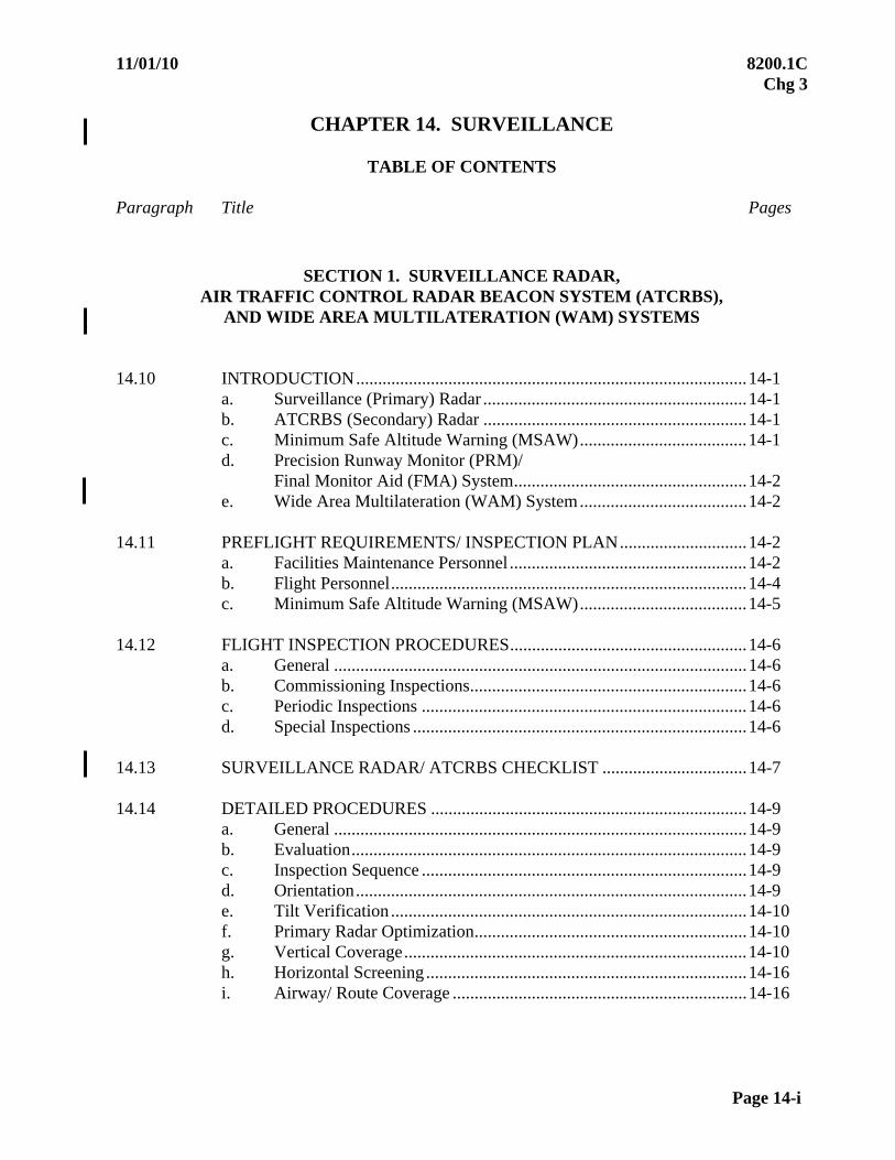
11/01/10 8200.1C Chg 3
Page 14-i
CHAPTER 14. SURVEILLANCE
TABLE OF CONTENTS
Paragraph Title Pages
SECTION 1. SURVEILLANCE RADAR, AIR TRAFFIC CONTROL RADAR BEACON SYSTEM (ATCRBS),
AND WIDE AREA MULTILATERATION (WAM) SYSTEMS 14.10 INTRODUCTION.........................................................................................14-1
a. Surveillance (Primary) Radar ............................................................14-1 b. ATCRBS (Secondary) Radar ............................................................14-1 c. Minimum Safe Altitude Warning (MSAW)......................................14-1 d. Precision Runway Monitor (PRM)/
Final Monitor Aid (FMA) System.....................................................14-2 e. Wide Area Multilateration (WAM) System......................................14-2
14.11 PREFLIGHT REQUIREMENTS/ INSPECTION PLAN.............................14-2
a. Facilities Maintenance Personnel ......................................................14-2 b. Flight Personnel.................................................................................14-4 c. Minimum Safe Altitude Warning (MSAW)......................................14-5
14.12 FLIGHT INSPECTION PROCEDURES......................................................14-6 a. General ..............................................................................................14-6 b. Commissioning Inspections...............................................................14-6 c. Periodic Inspections ..........................................................................14-6 d. Special Inspections ............................................................................14-6
14.13 SURVEILLANCE RADAR/ ATCRBS CHECKLIST .................................14-7 14.14 DETAILED PROCEDURES ........................................................................14-9
a. General ..............................................................................................14-9 b. Evaluation..........................................................................................14-9 c. Inspection Sequence ..........................................................................14-9 d. Orientation.........................................................................................14-9 e. Tilt Verification .................................................................................14-10 f. Primary Radar Optimization..............................................................14-10 g. Vertical Coverage..............................................................................14-10 h. Horizontal Screening .........................................................................14-16 i. Airway/ Route Coverage ...................................................................14-16
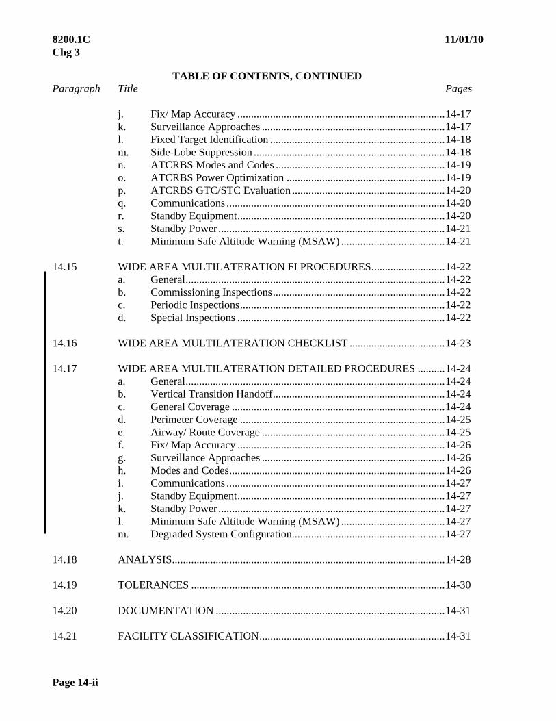
8200.1C 11/01/10 Chg 3
Page 14-ii
TABLE OF CONTENTS, CONTINUED Paragraph Title Pages
j. Fix/ Map Accuracy ............................................................................14-17 k. Surveillance Approaches ...................................................................14-17 l. Fixed Target Identification ................................................................14-18 m. Side-Lobe Suppression ......................................................................14-18 n. ATCRBS Modes and Codes ..............................................................14-19 o. ATCRBS Power Optimization ..........................................................14-19 p. ATCRBS GTC/STC Evaluation ........................................................14-20 q. Communications ................................................................................14-20 r. Standby Equipment............................................................................14-20 s. Standby Power ...................................................................................14-21 t. Minimum Safe Altitude Warning (MSAW) ......................................14-21
14.15 WIDE AREA MULTILATERATION FI PROCEDURES...........................14-22
a. General...............................................................................................14-22 b. Commissioning Inspections...............................................................14-22 c. Periodic Inspections...........................................................................14-22 d. Special Inspections ............................................................................14-22
14.16 WIDE AREA MULTILATERATION CHECKLIST ...................................14-23 14.17 WIDE AREA MULTILATERATION DETAILED PROCEDURES ..........14-24
a. General...............................................................................................14-24 b. Vertical Transition Handoff...............................................................14-24 c. General Coverage ..............................................................................14-24 d. Perimeter Coverage ...........................................................................14-25 e. Airway/ Route Coverage ...................................................................14-25 f. Fix/ Map Accuracy ............................................................................14-26 g. Surveillance Approaches ...................................................................14-26 h. Modes and Codes...............................................................................14-26 i. Communications ................................................................................14-27 j. Standby Equipment............................................................................14-27 k. Standby Power ...................................................................................14-27 l. Minimum Safe Altitude Warning (MSAW) ......................................14-27 m. Degraded System Configuration........................................................14-27
14.18 ANALYSIS....................................................................................................14-28 14.19 TOLERANCES .............................................................................................14-30 14.20 DOCUMENTATION ....................................................................................14-31 14.21 FACILITY CLASSIFICATION....................................................................14-31
11/01/10 8200.1C Chg 3
Page 14-iii
TABLE OF CONTENTS, CONTINUED Paragraph Title Pages
FIGURES
Figure 14-1 ASR/ ATCRBS Vertical Coverage Profile............................14-12 Figure 14-2 ARSR/ ATCRBS Vertical Coverage Profile .........................14-13 Figure 14-3 ASR/ ATCRBS .....................................................................14-15 Figure 14-4 ARSR/ ATCRBS ...................................................................14-15 Figure 14-5 Tolerances..............................................................................14-30
SECTION 2. PRECISION APPROACH RADAR (PAR)
14.22 INTRODUCTION.........................................................................................14-31 14.23 PREFLIGHT REQUIREMENTS..................................................................14-32
a. Facilities Maintenance Personnel ......................................................14-32 b. Flight Personnel.................................................................................14-32 c. Special Equipment Requirements......................................................14-32 d. Theodolite Procedures .......................................................................14-32
14.24 FLIGHT INSPECTION SPECIFICATIONS................................................14-33 14.25 CHECKLISTS...............................................................................................14-33
a. Generic PAR (FPN-40, FPN-62/63, MPN-14, TPN-18,TPN-44).....14-34 b. GPN-22, TPN-25...............................................................................14-35 c. TPN-22 ..............................................................................................14-37 d. MPN-25/ GCA-2000, TPN-31 (31/A), FPN-67 ................................14-39
14.26 FLIGHT INSPECTION PROCEDURES......................................................14-40 a. Course Alignment and Coverage (Azimuth) .....................................14-40 b. Azimuth Only Procedures .................................................................14-41 c. Course Deviation Accuracy...............................................................14-41 d. Range Accuracy.................................................................................14-41 e. Usable Distance .................................................................................14-41 f. Coverage (Lateral).............................................................................14-41 g. Moving Target Indicator (MTI)/
Moving Target Detector (MTD)........................................................14-42 h. Glidepath Alignment .........................................................................14-42 i. Application of Angle Tolerances.......................................................14-43

8200.1C 11/01/10 Chg 3
Page 14-iv
TABLE OF CONTENTS, CONTINUED Paragraph Title Pages
j. PAR Coincidence with Other Guidance ............................................14-44 k. Lower Safe Limit Alignment.............................................................14-44 l. Lighting Systems ...............................................................................14-44 m. Communications ................................................................................14-44 n. Standby Equipment............................................................................14-44 o. Standby Power ...................................................................................14-44
14.27 ANALYSIS....................................................................................................14-45 14.28 TOLERANCES .............................................................................................14-45 14.29 ADJUSTMENTS...........................................................................................14-45
SECTION 3. AUTOMATIC DEPENDENT SURVEILLANCE BROADCAST (ADSB)
14.30 Reserved
11/01/10 8200.1C Chg 3
Par 14.10 Page 14-1
CHAPTER 14. SURVEILLANCE
SECTION 1. SURVEILLANCE 14.10 INTRODUCTION. This chapter outlines procedures for the flight inspection of surveillance radar and the air traffic control radar beacon system (ATCRBS), referred to as secondary radar. Wide Area Multilateration (WAM) systems are also covered. The procedures for radar flight inspection differ from the procedures for NAVAID(s) in that most of the data collection and analysis are conducted on the ground. The flight inspector's role is primarily one of providing a known target in a designated area. Present digital techniques allow the evaluation of most radar parameters by the use of statistical sampling of aircraft returns in the normal day-to-day radar environment. Certain requirements must be completed using a flight inspection aircraft. Facilities maintenance personnel will use targets-of-opportunity, radar data analysis software (RDAS) tools, and other test equipment to the extent practicable for completing all checklist requirements. Facilities Maintenance personnel will normally evaluate and document all facility performance parameters, except those specifically evaluated by the flight inspector. Air Traffic Technical Operations will prepare a radar inspection plan for all commissioning inspections, as well as all special inspections involving coordination outside the facility of concern. Joint use facility (radar data used by both FAA and DOD) inspection plans require coordination between the FAA region and the DOD user.
a. Surveillance (Primary) Radar. Primary radar relies on reflected radio energy to provide a video target on the controller's display. The radar return varies in strength due to atmospheric conditions, target range, radar cross chapter, aircraft reflective surfaces, and other phenomena.
b. ATCRBS (Secondary) Radar. Secondary radar overcomes some of the basic problems of primary radar. Secondary radar relies on electronic replies from a transponder system in the aircraft, generated as a result of interrogations from the ground system. Transponder replies can be used for improved target identification (assigned beacon code) and for aircraft altitude information from Mode-C equipped transponders. The ATCRBS normally provides improved coverage over primary radar. ATCRBS coverage is a function of many factors, including siting and antenna patterns. The ATCRBS is normally inspected simultaneously with the primary radar system.
c. Minimum Safe Altitude Warning System (MSAW). MSAW is a software function of the Automated Radar Terminal System (ARTS) designed to generate an alert when an associated aircraft with Mode-C is at or predicted to be at an unsafe altitude. MSAW monitors aircraft for terrain and obstacle separation and will generate an alert, both aural and visual, on the display of the air traffic controller. MSAW consists of two detection components, the general terrain monitor (GTM) and the approach path monitor (APM).
8200.1C 11/01/10 Chg 3
Page 14-2 Par 14.10c
(1) General Terrain Monitor (GTM). The GTM exists within a radius of approximately 60 nm of the associated ASR site and consists of bins which are 2 nm square. Some locations may use half-mile square bins. When an aircraft is below, predicted to be below, or projected to be below the bin altitude, an alert is generated.
(2) Approach Path Monitor (APM). An APM is normally 1 nm wide, either side of final approach course or runway heading. An APM starts at approximately 5 nm (or final approach fix) from the approach end of runway. The APM terminates at approximately 1 nm from the approach end of the runway. An altitude value is determined for obstruction clearance for each APM at the beginning and at the end of the APM. These two values provide MSAW protection as an aircraft descends along the approach path towards the runway. Parallel runways utilize the same APM. For a circling only SIAP, the APM starts at 5 nm (or final approach fix) from the closest landing surface and terminates 1 – 2 nm from the closest landing surface.
d. Precision Runway Monitor (PRM)/ Final Monitor Aid (FMA) System. The PRM is a high update mono-pulse secondary surveillance radar system that employs an electronically scanned phased array antenna and high-resolution color monitors. It is used to monitor ILS/ MLS approaches on runways whose extended centerlines are separated by at least 3,400 ft, but less than 4,300 ft. In addition, runway separation may be decreased to 3,000 ft if the localizer courses are aligned at least 2 1/2 to 3 divergent to each other. A simultaneous offset instrument approach is applicable where parallel runway centerlines are from 750 to 3,000 ft apart. High-resolution color monitoring displays with visual and audible alerts, called Final Monitor Aids (FMA(s)) are required to present surveillance track data to controllers, along with detailed maps depicting approaches and the no transgression zone. Flight inspection of the PRM system will be conducted IAW FAA Order 8200.39, Flight Inspection of Precision Runway Monitors/ Final Monitor Aid Systems, until it is incorporated into this order.
e. Wide Area Multilateration (WAM) System. WAM is a surveillance system that uses multiple sensors to detect, identify, display, and track targets. WAM uses a constellation of ground stations, or Remote Units (RU), to provide surveillance coverage within a defined region. WAM makes use of signals transmitted from Air Traffic Control Beacon System (ATCRBS) aircraft transponders, including Mode A, Mode C, and Mode S, to calculate an aircraft’s position. The WAM system also processes signals from ADS-B Mode-S extended squitter transponders. When an ADS-B message is received at three or more remote units, a Multilateration report can be generated. WAM can be configured as a Virtual radar, feeding data to an automation system (e.g., MEARTS) for display to air traffic controllers. 14.11 PREFLIGHT REQUIREMENTS/ INSPECTION PLAN. The AF regional maintenance engineering office and/or military equivalent is responsible for preparing the Operational Performance Inspection Plan in accordance with FAA Order 6300.13, Radar Systems Optimization and Flight Inspection. An inspection plan is required for all commissioning inspections and special inspections requiring coordination outside the facility of concern. Simple special inspections that do not require coordination outside the local AF/ Maintenance and AT offices may not require a formal inspection plan but should always be documented. Representatives of Air Combat Command (ACC) will participate in the planning and inspections of a Joint Surveillance Site (JSS).

11/01/10 8200.1C Chg 3
Par 14.11a Page 14-3
a. Facilities Maintenance Personnel. The appointee preparing the inspection plan must coordinate with all associated offices. For en route sites, the attendees must be: AF representatives from the ARTCC and the remote site, AT representatives from the regional office and the ARTCC, and a flight inspection representative. The DOD user and appropriate ACC representative should attend planning meetings to identify operational requirements and evaluation objectives for a JSS. For terminal radar inspections, the appointed coordinators must include AT representatives from the region and local site, an AF representative from the systems maintenance office, and a flight inspection representative. Military offices must provide plan preparation and the required coordination for joint use and military sites. The appointee for special plan preparation must be assisted by representatives from each office of concern. This assistance will be requested from specific offices when required. In addition to the procedures specified in Chapter 4, Facilities Maintenance personnel must ensure the following items are addressed in the inspection plan:
(1) The Objectives of the Inspection. These objectives will determine who must assist and provide input for the draft of the plan, the methods used to perform the various checks, and what checks will be performed by Facilities Maintenance personnel and flight inspection.
(2) Prepare a List of Operational Requirements. These requirements must describe in detail all routes, fixes, holding patterns, and approach and departure procedures. These details must include specified altitudes, distances, and other pertinent information. The list of routes, fixes, etc., may then be divided between evaluations using targets-of-opportunity and those requiring a flight inspection aircraft. A flight inspection aircraft will normally be used in areas with low traffic activity, where siting criteria predicts marginal or no coverage, or where fix/ map accuracy must be determined. The flight inspection phase of the plan may be further divided into checks requiring an aircraft with a calibrated transponder and those which can be completed using a small aircraft equipped with an approved transponder. When assigned to inspect or evaluate a military/ JSS facility, the ACC representative must perform all coordination and notification requirements, complete the flight phase planning, and publish required documents.
(3) Describe the Resources Required. This list must include personnel, aircraft, special tools and equipment, equipment calibration, computer time and software, charts, graphs, maps, etc. The inspection plan must also include all data required to prepare, conduct, and document the inspection.
(4) Flight Scheduling. Recommend, if appropriate, the best flight period for evaluating coverage. The flight period will usually be a compromise between operational and engineering needs. This compromise is required because AT prefers to handle flight inspection aircraft during periods of low traffic activity; however, the AF engineer may require some portions of coverage checks during peak traffic periods.
(5) Radar Equipment Performance. Ensure the radar equipment is tuned to facility operational specifications prior to the flight inspection. A joint inspection is required to measure and optimize JSS equipment parameters.

8200.1C 11/01/10 Chg 3
Page 14-4 Par 14.11a
(6) Participating Personnel. Ensure participating maintenance and operations personnel (including military) are experienced and familiar with the objectives of the inspection and the requirements of this order.
(7) Inspection Plan Ensure the inspection plan includes a sequence of events to minimize aircraft flight time and the inconvenience to operating traffic. This portion of the plan must be used as a schedule of events during the inspection activities.
(8) Final Plan. Ensure the final plan is reviewed and signed by representatives from AT, the FIFO, the military when appropriate, and AF.
(9) Consolidated Inspection Data. Consolidate and evaluate all inspection data obtained using targets-of-opportunity and advise the flight inspector of additional checks that require the use of a flight inspection aircraft.
(10) Interrogator Calibration Values. Furnish the interrogator power values (in watts at the antenna) for inclusion in the flight inspection report.
b. Flight Personnel. Prepare for the flight inspection in accordance with Chapter 4. In addition:
(1) Flight Inspection Coordination. The Flight Inspector will establish contact with the personnel responsible for the radar inspection plan. This may be someone from Air Traffic Technical Operations, a service area engineer, or DoD personnel for military facilities. Pre-inspection coordination should be accomplished in concert with the maintenance actions listed in Paragraph 14.11a. Simple special inspections that do not require coordination outside the local AF/ Maintenance and AT offices may not require a formal inspection plan but should always be documented.
(2) Inspection Plan. A copy of the inspection plan and a current briefing concerning the operational requirements, expected facility performance, and the performance evaluations obtained using targets-of-opportunity must be provided to the flight inspector. This information will be used to determine the extent of the flight inspection.
(3) Checklist Requirements. Assist Facilities Maintenance personnel in determining which checklist requirements have been completed. The role of the flight inspector will vary greatly depending upon the type, sophistication, intended use, and location of the radar facility. For instance, an FAA en route radar may only require the flight inspector complete a portion of the vertical coverage check, whereas a mobile terminal radar may require a dedicated aircraft for all the checklist requirements.

11/01/10 8200.1C Chg 3
Par 14.11b Page 14-5
(4) Aircraft Requirements. Flight inspection aircraft used for ATCRBS and primary radar checks are equipped with a transponder that has been FAA-calibrated in accordance with applicable avionics maintenance standards. The transponder power output and sensitivity are pilot-selectable per the following table.
FLIGHT INSPECTION TRANSPONDER
SWITCH SETTINGS
FLIGHT INSPECTION TRANSPONDER PARAMETERS
Flt Insp Select
Lo-Power Select
Rx Sensitivity
Tx Power
OFF OFF Normal (-75 dBm)
Normal (350 watts)
ON (barber pole lit)
OFF Low (-69 dBm)
Normal (350 watts)
ON (barber pole lit)
ON (barber pole lit)
Low (-69 dBm)
Low (88 watts)
c. Minimum Safe Altitude Warning (MSAW). Flight inspection of MSAW is a test
of the ARTS software. There are no flight inspection tolerances. The flight inspection crew will fly the detailed procedures as outlined in Paragraph 14.14t. One General Terrain Monitor (GTM) check will be completed during the periodic interval. The flight inspection aircraft is a dedicated target for the alert check. Air Traffic/ AOS determines the final status of MSAW.
(1) Preflight Coordination. The flight inspector must ensure the following:
(a) Site-specific data required for the check is included in the inspection request. If not able to obtain the necessary data from the requestor, contact the MSAW Quality Assurance Team.
(b) Coordination with the air traffic representative has been accomplished prior to beginning an inspection.
(c) The altitudes to be flown and MSAW altitude alert points are clearly defined and understood.
(d) Conduct all flight inspection for MSAW in day VFR conditions.
(2) MSAW is an ARTS software function. MSAW results do not affect the associated ASR status.
8200.1C 11/01/10 Chg 3
Page 14-6 Par 14.12
14.12 FLIGHT INSPECTION PROCEDURES.
a. General. Radar flight inspections may vary from a single (special inspection) requirement such as radar coverage over a new air traffic "fix," to a complete en route radar commissioning inspection at an ARTCC. The number of personnel, coordination, preparation, and reporting required for inspections varies widely. An inspection normally consists of three distinct parts; planning, engineering, and documentation. The planning phase results in the flight inspection plan. The engineering or equipment phase includes necessary tests to ensure the radar system performs to design specifications.
Although this phase is primarily an AF engineering function, some tests may require a flight inspection aircraft. When multiple approved procedures are listed, the AF engineering representative can select which procedure is to be used. The tests required during the engineering phase are referenced in Paragraph 14.13, Checklist, and Paragraph 14.14 Detailed Procedures. The documentation or flight inspection portion determines if AT requirements are met and establishes a radar coverage baseline. AT requirements are outlined in the facility siting report and the inspection plan. The detailed flight inspection procedures are covered under Paragraph 14.14. See Paragraphs 14.15 through 14-17 for instructions specific to Wide Area Multilateration systems.
b. Commissioning Inspections. The objective of the commissioning inspection is to evaluate system performance, determine and document the site coverage, and provide a baseline for the detection of a deterioration in equipment performance. Data obtained during this inspection will be used for daily comparison of facility performance, as well as future inspections. The commissioning is the most thorough inspection and requires a correspondingly detailed plan and report.
c. Periodic Inspections. ASR(s) with either surveillance approaches or MSAW function require a periodic flight inspection.
d. Special Inspections. Special inspections are conducted to fulfill a particular need and may be very limited in scope. The limited inspection may not require a formal written plan, and only a short inspection report. If equipment changes or modifications to commissioned facilities change the coverage pattern, document the changes in the inspection report. The new coverage pattern then becomes the basis for comparison during subsequent inspections. Coordination with appropriate military personnel is vital at joint-use sites. Special inspections include the following:
(1) Engineering Support. Engineering support is performed to help engineering and AT personnel determine if the radar meets equipment certification and operational requirements. This data may be used for commissioning purposes, provided no equipment modifications are made prior to the commissioning inspection. Requirements for specific checks will be determined by Facilities Maintenance personnel and need not conform to a specific format.
11/01/10 8200.1C Chg 3
Par 14.12 Page 14-7
(2) Antenna Change. Paragraph 14.13, Checklist, identifies requirements for the installation of a new antenna of the same or different type. If there is a question concerning the characteristics or type of antenna being installed, the AF engineer in charge will determine which antenna change checklist applies. A flight inspection is not required following an antenna pedestal or rotary joint change, provided the ground measurements of the reflector position, feedhorn alignment, and antenna tilt of the replacement pedestal, are satisfactory. Refer to Paragraphs 14.14f(4)(d) and (e) for antenna change procedures.
(3) Major Modifications (other than antenna change). This inspection plan, inspection, and report should be confined to the parameters necessary to confirm facility performance. The radar engineer must determine the extent of a special inspection during preparation and coordination of the plan. Depending upon the extent of the modification, an inspection using RDAS tools and targets-of-opportunity may satisfy the inspection requirements.
(4) Near-Midair-Collision Inspections. These inspections are conducted at the request of the AT manager of the facility involved. The inspection determines the radar coverage in the area where the incident occurred. The flight inspection must be conducted as soon as possible following the near-midair-collision, duplicating the maneuvers, altitude, and direction of flight of the incident aircraft. The radar must be operated in the same configuration, to the extent practicable, as it was at the time of the incident. Near-midair flight inspection reports must be submitted in the same manner as after-accident reports (see Order 8240.36, Flight Inspection Report Processing System). 14.13 SURVEILLANCE RADAR/ ATCRBS CHECKLIST. The checks requiring a flight inspection aircraft are identified in the checklist and appropriate "detailed procedure" paragraphs. The procedures presented here may be used singly when a special inspection may be satisfied with one or more of the individual tests. The checklist items identified by an "X" are mandatory. Facilities Maintenance personnel must evaluate the data obtained using targets-of-opportunity to determine if further evaluation by a flight inspection aircraft is required. The flight inspector must consult with the radar engineer prior to departing the area to ensure that all checklist requirements have been completed.
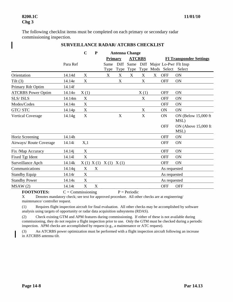
8200.1C 11/01/10 Chg 3
Page 14-8 Par 14.13
The following checklist items must be completed on each primary or secondary radar commissioning inspection.
SURVEILLANCE RADAR/ ATCRBS CHECKLIST
C P Antenna Change Primary ATCRBS FI Transponder Settings Para Ref Same
Type Diff Type
Same Type
Diff Type
Major Mods
Lo-Pwr Select
Flt Insp Select
Orientation 14.14d X X X X X X OFF ON Tilt (3) 14.14e X X X OFF ON Primary Rdr Optim 14.14f ATCRBS Power Optim 14.14o X (1) X (1) OFF ON SLS/ ISLS 14.14m X X OFF ON Modes/Codes 14.14n X OFF ON GTC/ STC 14.14p X X ON ON Vertical Coverage 14.14g X X X ON ON (Below 15,000 ft
MSL) OFF ON (Above 15,000 ft
MSL) Horiz Screening 14.14h OFF ON Airways/ Route Coverage 14.14i X,1 OFF ON
Fix /Map Accuracy 14.14j X OFF ON Fixed Tgt Ident 14.14l X OFF ON
Surveillance Apch 14.14k X (1) X (1) X (1) X (1) OFF ON Communications 14.14q X X As requested
Standby Equip 14.14r X As requested
Standby Power 14.14s X As requested
MSAW (2) 14.14t X X OFF OFF
FOOTNOTES: C = Commissioning P = Periodic X Denotes mandatory check; see text for approved procedure. All other checks are at engineering/ maintenance/ controller request.
(1) Requires flight inspection aircraft for final evaluation. All other checks may be accomplished by software analysis using targets of opportunity or radar data acquisition subsystems (RDAS).
(2) Check existing GTM and APM features during commissioning. If either of these is not available during commissioning, they do not require a flight inspection prior to use. Only the GTM must be checked during a periodic inspection. APM checks are accomplished by request (e.g., a maintenance or ATC request).
(3) An ATCRBS power optimization must be performed with a flight inspection aircraft following an increase in ATCRBS antenna tilt.

11/01/10 8200.1C Chg 3
Par 14.14 Page 14-9
14.14 DETAILED PROCEDURES
a. General. Facilities Maintenance personnel must use operational displays for target grading and guidance information. Facilities Maintenance personnel must configure the radar in its lowest usable configuration (the traditional worst case configuration, all enhancements on, may degrade newer "smart" radars to the point that they become unusable). Data from the operational displays and automation diagnostic and analysis programs will determine if the system supports operational requirements. When using targets-of-opportunity, multiple target returns are required to ensure accuracy. Verify questionable accuracy with a flight inspection aircraft.
b. Evaluation ATCRBS and primary radar must be evaluated simultaneously throughout the inspection whenever possible. If ATCRBS replies obscure the primary targets, the displayed ATCRBS should be offset slightly to allow evaluation of both replies.
c. Inspection Sequence. The engineer must ensure the radar facility is operating according to design specifications before any inspection tests begin. The inspection should start with orientation, tilt, and an initial ATCRBS power setting. During installation, the antenna is normally set to the tilt recommended in the siting report and the azimuth is set to a prescribed reference. These settings should provide adequate accuracy for the initial tests. The initial ATCRBS power may be set to either a theoretical value or a setting that will interrogate aircraft at maximum radar range. After refining these preliminary settings and becoming confident in them, the engineer should use targets-of-opportunity to ensure that primary and secondary coverage is at least as good as that required in the overall quality test. Tests which can be completed without using a flight inspection aircraft should be conducted prior to the arrival of the flight inspection aircraft. At joint-use sites, inspection sequence may vary, in order to satisfy the requirements of all agencies concerned.
NOTE: Parameter changes that occur during the flight inspection aircraft evaluation may require a repetition of previously conducted tests.
d. Orientation
(1) Purpose. To verify the radar azimuth corresponds with a known azimuth position and may be conducted with a flight inspection aircraft or ground check.
(2) Approved Procedures
(a) Fly inbound or outbound radially over a well-defined ground checkpoint or position the aircraft using AFIS. The altitude and distance of the checkpoint should be well inside the radar coverage limits.
(b) A radar PE, maintenance beacon, or MTI reflector of known location may be used to determine alignment of the radar azimuth in lieu of a flight inspection aircraft.
(3) Evaluation. Compare the azimuth observed by the controller with the magnetic azimuth of the checkpoint.
8200.1C 11/01/10 Chg 3
Page 14-10 Par 14.14e
e. Tilt Verification
(1) Purpose. To verify the primary and secondary radar antenna tilt settings are optimum and the mechanical antenna tilt indicators are accurate.
(2) Approved Procedure. Facilities Maintenance personnel must direct the aircraft through the heaviest ground clutter within operational areas so the predetermined angle can be evaluated and adjustments made if required. If radar coverage is acceptable and the radar range is satisfactory, complete the remaining portions of the flight inspection. If parameters are not acceptable, it will be necessary to reestablish the antenna tilt angle. In this case, re-accomplish any previously completed flight inspection procedures using the new antenna tilt angle.
(3) Evaluation. The tilt selection process considers the interaction of various radar parameters and the final radar system performance. The optimum tilt angle is a compromise between coverage (with/ without MTI) over clutter and range coverage.
f. Primary Radar Optimization
(1) Purpose. To aid in maximizing the radar's potential. Adjustments in STC, beam gating, receiver sensitivity, pulse width, etc., may improve a radar's performance.
(2) Approved Procedure. Facilities Maintenance personnel will provide a detailed flight profile.
(3) Evaluation. Facilities Maintenance personnel will observe the target display and adjust the radar as necessary.
g. Vertical Coverage
(1) Purpose. To determine and document the coverage in the vertical plane of the primary and ATCRBS antenna patterns. Evaluate the inner and outer fringes on all primary and secondary radars.
(2) Vertical Coverage Azimuth. Maintenance should choose an azimuth from the radar antenna or coincident VOR/ TACAN radial from the radar antenna which is free of clutter, dense traffic, heavy population areas, and interference created by line-of-site obstructions. Conduct the commissioning inspection and all subsequent inspections concerning facility performance, on the same azimuth for comparison purposes. For inspection at altitudes above flight inspection aircraft service ceiling, Air Traffic Technical Operations/ Air Traffic has the option of using targets of opportunity/ RDAS.
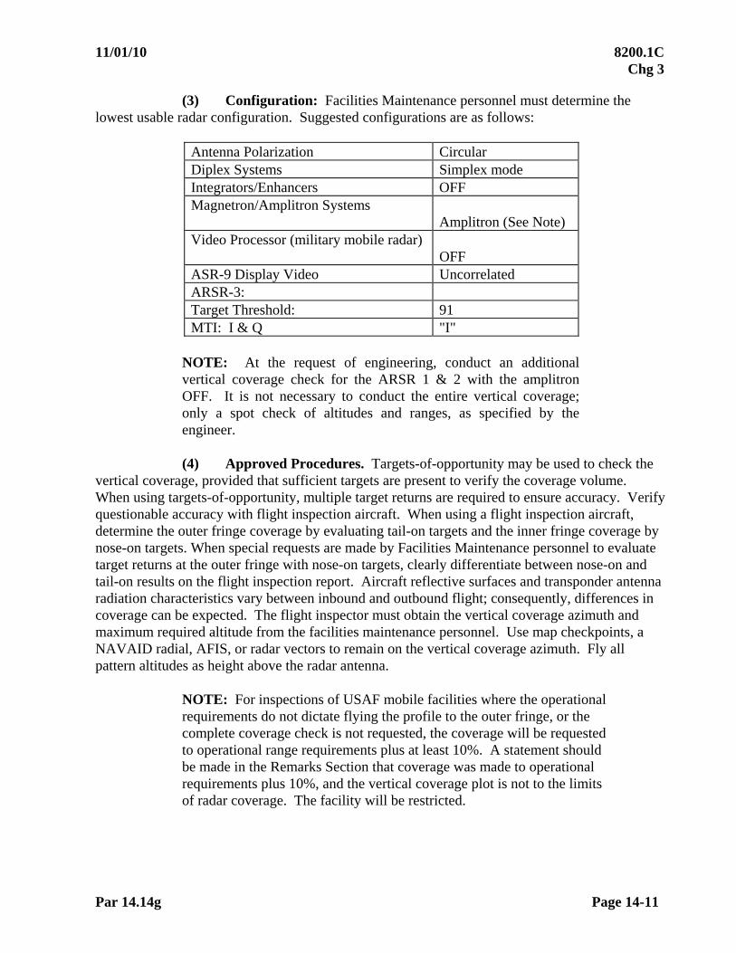
11/01/10 8200.1C Chg 3
Par 14.14g Page 14-11
(3) Configuration: Facilities Maintenance personnel must determine the lowest usable radar configuration. Suggested configurations are as follows:
Antenna Polarization Circular Diplex Systems Simplex mode Integrators/Enhancers OFF Magnetron/Amplitron Systems
Amplitron (See Note) Video Processor (military mobile radar)
OFF ASR-9 Display Video Uncorrelated ARSR-3: Target Threshold: 91 MTI: I & Q "I"
NOTE: At the request of engineering, conduct an additional vertical coverage check for the ARSR 1 & 2 with the amplitron OFF. It is not necessary to conduct the entire vertical coverage; only a spot check of altitudes and ranges, as specified by the engineer.
(4) Approved Procedures. Targets-of-opportunity may be used to check the
vertical coverage, provided that sufficient targets are present to verify the coverage volume. When using targets-of-opportunity, multiple target returns are required to ensure accuracy. Verify questionable accuracy with flight inspection aircraft. When using a flight inspection aircraft, determine the outer fringe coverage by evaluating tail-on targets and the inner fringe coverage by nose-on targets. When special requests are made by Facilities Maintenance personnel to evaluate target returns at the outer fringe with nose-on targets, clearly differentiate between nose-on and tail-on results on the flight inspection report. Aircraft reflective surfaces and transponder antenna radiation characteristics vary between inbound and outbound flight; consequently, differences in coverage can be expected. The flight inspector must obtain the vertical coverage azimuth and maximum required altitude from the facilities maintenance personnel. Use map checkpoints, a NAVAID radial, AFIS, or radar vectors to remain on the vertical coverage azimuth. Fly all pattern altitudes as height above the radar antenna.
NOTE: For inspections of USAF mobile facilities where the operational requirements do not dictate flying the profile to the outer fringe, or the complete coverage check is not requested, the coverage will be requested to operational range requirements plus at least 10%. A statement should be made in the Remarks Section that coverage was made to operational requirements plus 10%, and the vertical coverage plot is not to the limits of radar coverage. The facility will be restricted.
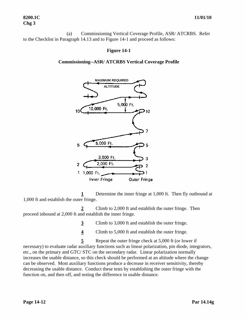
8200.1C 11/01/10 Chg 3
Page 14-12 Par 14.14g
(a) Commissioning Vertical Coverage Profile, ASR/ ATCRBS. Refer to the Checklist in Paragraph 14.13 and to Figure 14-1 and proceed as follows:
Figure 14-1
Commissioning--ASR/ ATCRBS Vertical Coverage Profile
MAXIMUM REQUIRED
ALTITUDE
1 Determine the inner fringe at 1,000 ft. Then fly outbound at 1,000 ft and establish the outer fringe.
2 Climb to 2,000 ft and establish the outer fringe. Then proceed inbound at 2,000 ft and establish the inner fringe.
3 Climb to 3,000 ft and establish the outer fringe.
4 Climb to 5,000 ft and establish the outer fringe.
5 Repeat the outer fringe check at 5,000 ft (or lower if necessary) to evaluate radar auxiliary functions such as linear polarization, pin diode, integrators, etc., on the primary and GTC/ STC on the secondary radar. Linear polarization normally increases the usable distance, so this check should be performed at an altitude where the change can be observed. Most auxiliary functions produce a decrease in receiver sensitivity, thereby decreasing the usable distance. Conduct these tests by establishing the outer fringe with the function on, and then off, and noting the difference in usable distance.
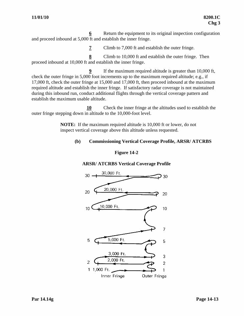
11/01/10 8200.1C Chg 3
Par 14.14g Page 14-13
6 Return the equipment to its original inspection configuration and proceed inbound at 5,000 ft and establish the inner fringe.
7 Climb to 7,000 ft and establish the outer fringe.
8 Climb to 10,000 ft and establish the outer fringe. Then proceed inbound at 10,000 ft and establish the inner fringe.
9 If the maximum required altitude is greater than 10,000 ft, check the outer fringe in 5,000 foot increments up to the maximum required altitude; e.g., if 17,000 ft, check the outer fringe at 15,000 and 17,000 ft, then proceed inbound at the maximum required altitude and establish the inner fringe. If satisfactory radar coverage is not maintained during this inbound run, conduct additional flights through the vertical coverage pattern and establish the maximum usable altitude.
10 Check the inner fringe at the altitudes used to establish the outer fringe stepping down in altitude to the 10,000-foot level.
NOTE: If the maximum required altitude is 10,000 ft or lower, do not inspect vertical coverage above this altitude unless requested.
(b) Commissioning Vertical Coverage Profile, ARSR/ ATCRBS
Figure 14-2
ARSR/ ATCRBS Vertical Coverage Profile

8200.1C 11/01/10 Chg 3
Page 14-14 Par 14.14g
1 Complete steps (1) through (8) of the ASR commissioning requirements in Paragraph 14.14g(4)(a).
2 Climb to 20,000 ft and establish the outer fringe. Then proceed inbound at 20,000 ft and establish the inner fringe.
3 Climb to 30,000 ft and establish the outer fringe.
4 Repeat the outer fringe as required to conduct auxiliary functions tests.
5 Then proceed inbound at 30,000 ft and establish the inner fringe.
6 If operational or engineering requirements are greater than 30,000 ft, or 30,000 ft conflicts with air traffic, climb to a mutually agreeable altitude and establish the outer and inner fringes.
(c) Commissioning Inspection - Military BRITE/ DBRITE Display. Inspect an ASR which has the sole function of providing a video source for a BRITE/ DBRITE display to operational requirements or 4,000 ft/ 10 miles, whichever is greater.
1 Determine the inner and outer fringes at every 1,000-foot level up to 4,000 ft or the operational altitude.
2 No comparative equipment auxiliary function configuration checks are required.
3 Target definition will be from the BRITE display.
4 There are no periodic inspection requirements.
(d) Primary Radar Antenna Change. When the primary ASR or ARSR antenna is changed, fly the vertical coverage profile depicted in Figure 14-3 or 14-4, as applicable.
1 After determining the outer fringe at 5,000 ft, repeat the outer fringe check, as required, to evaluate auxiliary functions as requested by facilities maintenance personnel. Conduct the remainder of the coverage check in the original configuration.
2 Checks of additional facility equipment configurations and altitudes will be at the option of Facilities Maintenance personnel.

11/01/10 8200.1C Chg 3
Par 14.14g Page 14-15
(e) ATCRBS Antenna Change. When replacing the antenna with the same type, all inspection requirements may be completed using targets-of-opportunity. When the antenna is replaced with a different type, checklist requirements must be completed using a flight inspection aircraft as required by the Checklist.
1 Terminal Radar. The profile for a primary radar antenna change is indicated in Figure 14-3.
Figure 14-3
Antenna Change--ASR/ ATCRBS
Maximum Required Altitude
2 En Route Radar. The profile for a primary radar antenna change is indicated in Figure 14-4.
Figure 14-4
Antenna Change--ARSR/ ATCRBS

8200.1C 11/01/10 Chg 3
Page 14-16 Par 14.14g
(5) Evaluation. Facilities Maintenance personnel must record target strength as defined in Paragraph 14.16 on each scan, aircraft position every five miles, and aircraft altitude for each fringe check and level run. Facilities Maintenance personnel must document results of the vertical coverage check using analysis/ diagnostic programs (RDAS tools), when available, for inclusion in the facility report.
h. Horizontal Screening
(1) Purpose. To verify the indicated coverage on the horizontal screening charts. This test is optional depending upon operational requirements and ground evaluation tools available. After reviewing the results of the vertical coverage check and other data, engineering personnel will determine if the horizontal coverage check is required.
(2) Approved Procedure. Fly an orbit at an altitude and distance which corresponds to the lowest screening angle at which coverage is expected. Do not use an orbit radius of less than ten miles. AFIS, DME, or vectors provided by the controller may be used to maintain the orbit. MTI, if used, should be gated to a range inside the orbit radius, except where ground clutter obscures the targets unless MTI is used. If MTI is gated outside of the orbit, the radius of the orbit must be constantly changed to avoid target cancellation due to tangential blind speed. For example, vary the distance on a 12-mile orbit between 10 and 14 miles, flying oblique straight courses between the 10-mile and 14-mile orbits, so as to average a 12-mile orbital distance.
(3) Evaluation. Facilities Maintenance personnel must record target strength, azimuth and distance every scan. They must determine if the coverage supports operational requirements.
i. Airway/ Route Coverage
(1) Purpose: To document coverage along routes and airways, required by AT. Facilities Maintenance personnel must determine the extent of these evaluations which determine the overall radar facility coverage. Areas of intense clutter, poor target returns, or other potential problems identified in the inspection plan may be further evaluated to determine actual facility coverage. This check must be accomplished using targets-of-opportunity with the final commissioning check done with a flight inspection aircraft.
(2) Approved Procedures
(a) Facilities Maintenance personnel must configure the primary radar in "circular polarization". The altitudes at which satisfactory radar coverage exists will be determined by flying the minimum altitude (not lower than MOCA) on airway centerline. The terminal arrival and departure routes and other areas of interest identified in the inspection plan will be flown at MOCA. Maintain course guidance by reference to AFIS, ground checkpoints, NAVAID signals, or radar vectors. Coverage verification using linear polarization may be checked at the discretion of the test engineer or, if a joint use site, by the DOD agency.

11/01/10 8200.1C Chg 3
Par 14.14i Page 14-17
(b) Targets-of-Opportunity. Targets may consist of one or an assortment of aircraft returns on a particular airway, route or terminal radial. Targets used must be mode-C equipped so altitude information can be obtained. Scoring may be accomplished by either RDAS tools or manually. RDAS may be used to evaluate the track information of a selected (beacon code) target.
(3) Evaluation. Facilities Maintenance personnel must determine if the facility coverage meets operational requirements.
j. Fix/ Map Accuracy
(1) Purpose. To verify all airways, routes, fixes, and runway centerlines on the video map display. Replacement map overlays, video maps, or digitally-generated maps do not require a flight inspection if Facilities Maintenance personnel can determine, using targets-of-opportunity, that the new map is accurate.
(2) Approved Procedure. The flight inspector must fly the minimum altitude where satisfactory radar coverage exists using NAVAID guidance, ground checkpoints, or AFIS to identify the airway, route, or fix. The procedure is the same whether using a flight inspection aircraft or targets-of-opportunity; Facilities Maintenance personnel compare reported aircraft position relative to the airway, route, or fix with the video map presentation. Similarly, verify runway centerline to video map alignment by observing landing and departing aircraft.
(3) Evaluation. Compute the distance between the airway, route or fix, and the aircraft position, and apply the appropriate tolerance.
(4) Radar Overlays. Flight inspection of radar map overlays used as a backup for a video map need not be accomplished, provided the overlay contains data which is identical to a video map display which has been satisfactorily inspected. Any data on an overlay that differs from the video map display must be inspected before use. This applies to new or replacement map overlays.
k. Surveillance Approaches
(1) Purpose. All ASR approaches must be checked for accuracy and coverage by a flight inspection aircraft during commissioning inspections or any time a new approach procedure is developed. ASR approaches must be checked on a periodic basis. Surveillance approaches must be evaluated using surveillance type radar scopes. Conducting an ASR approach on a PAR display is not acceptable for flight inspection purposes. ASR approaches are not authorized using ATCRBS only, and the ATCRBS display should be offset.
(a) Approach to a Runway. The approach course must coincide with the runway centerline extended and must meet accuracy and coverage tolerances.

8200.1C 11/01/10 Chg 3
Page 14-18 Par 14.14k
(b) Approach to an Airport. The approach course must be aligned to the MAP as determined by procedures and Facilities Maintenance personnel. Helicopter-only final approach courses may be established to a MAP no farther than 2,600 ft from the center of the landing area.
(2) Approved Procedure. The controller must provide vectors for a 10-mile ASR final approach. The flight inspector must fly at MVA until reaching the final approach segment. Prior to the final segment, compare published minimum descent altitude (MDA) with MDA provided by the air traffic controller. The final approach segment must be flown flying headings as provided by the air traffic controller. Descend to the minimum descent altitude and verify recommended altitudes on final. The flight inspector must evaluate the approach procedure, evaluate the aircraft position relative to the runway centerline extended/ airport, and determine if a landing can be made without excessive maneuvering.
(3) Evaluation. ASR approaches must meet flight inspection tolerances or be canceled by appropriate NOTAM action. The cancellation of an ASR approach does not constitute a restriction on the radar facility. When MTI is required for an ASR approach, information must be documented on the flight inspection report. The use of MTI does not constitute a facility restriction; however, ASR approaches which require MTI are NOT authorized when this feature is inoperative.
l. Fixed Target Identification
(1) Purpose. To identify prominent, primary broadband targets used for range and azimuth accuracy checks when they cannot be identified by other means. This check may be accomplished using targets-of-opportunity or flight inspection aircraft.
(2) Approved Procedure. Facilities Maintenance personnel will select identifiable features from a comparison of the ground clutter return and geographic maps (islands, mountain peaks, towers, etc.). They should direct the pilot to the PE return. If the pilot can identify and describe the ground target, and the target is a permanent feature, record the PE in the inspection report.
(3) Evaluation. The pilot must identify and record a description of the PE for inclusion in the inspection report.
m. Side-Lobe Suppression.
(1) Purpose. To set transmitter power levels in the beacon SLS or ISLS antenna elements. The use of SLS/ ISLS improves beacon performance, reducing or eliminating ring-around caused by the side lobes of the antenna pattern. ISLS also reduces false targets which are normally caused by close, vertical reflecting surfaces. This check may be accomplished using targets-of-opportunity or flight inspection aircraft.
11/01/10 8200.1C Chg 3
Par 14.14m Page 14-19
(2) Approved Procedure. Facilities Maintenance personnel must select azimuths to be checked in areas where side lobe problems have occurred in the past. Fly these radials at 1,000 ft above the radar site elevation to the coverage limits (normally line-of-sight). Facilities Maintenance personnel must adjust the SLS or ISLS power levels while observing beacon inner-range coverage. The power levels must be adjusted for minimum ring-around and false target returns. After making final adjustments, ensure that inner range coverage is still satisfactory.
(3) Evaluation. Facilities Maintenance personnel must evaluate SLS/ ISLS performance.
n. ATCRBS Modes and Codes
(1) Purpose: To verify the proper decoding of ATCRBS reply pulses. Facilities Maintenance personnel must ensure that all modes and codes are verified by equipment test procedures before requesting flight inspection. Codes 7500, 7600, and 7700 should not be used due to the possibility of alarming other facilities.
(2) Approved Procedure. Facilities Maintenance personnel must monitor the flight inspection aircraft transponder replies or targets-of-opportunity throughout the vertical coverage, airway, route, and terminal checks to verify correct altitude readout. During these tests, Facilities Maintenance personnel should request the flight inspection aircraft use different modes or codes to sample various modes and code trains. When targets-of-opportunity are used, ensure that the sample contains all modes interrogated and a sufficiently large sample of codes to ensure correct decoding of beacon replies.
(3) Evaluation. Facilities Maintenance personnel must ensure the displayed transponder reading agrees with the aircraft transponder setting.
o. ATCRBS Power Optimization
(1) Purpose: To reduce over-interrogation, over-suppression, fruit, and false targets caused by reflections. Optimum ATCRBS power must be the minimum ATCRBS power to meet operational requirements.
(2) Approved Procedures. The aircraft must be positioned to fly an arc in the vicinity of the vertical coverage radial or mutually agreed to reference radial at maximum distance. The aircraft altitude must be 10,000 ft for ASR(s) and 30,000 ft for ARSR(s), or as close to these altitudes as operational conditions allow. The beacon transmitter power must be adjusted to the minimum value that produces a usable beacon reply or target. During this check, ensure that the aircraft transponder antenna is not shielded by aircraft. An ATCRBS power optimization must be performed with a flight inspection aircraft following an increase in antenna tilt.
Vertical coverage as flown by a flight inspection aircraft or targets-of-opportunity must be checked using the power level established in this paragraph. The beacon must be commissioned at this power level, plus 1 dB.

8200.1C 11/01/10 Chg 3
Page 14-20 Par 14.14o
(3) Evaluation. Facilities Maintenance personnel must observe ATCRBS performance during the ATCRBS power optimization for a usable beacon reply.
NOTE: Although this test may be accomplished during the vertical coverage check, any changes made in beacon power, as a result of this test, will invalidate any portion of the flight inspection checked previously.
p. ATCRBS GTC/ STC Evaluation
(1) Purpose: To evaluate the ATCRBS GTC/ STC setting. It must be adjusted prior to the flight inspection and confirmed during the vertical and airway/ route coverage checks. GTC/ STC reduces the interrogator receiver gain, as the range to the station reduces, thereby reducing ring-around and false targets.
(2) Approved Procedures
(a) Facilities Maintenance personnel must observe the flight inspection aircraft target for ring-around, during the vertical coverage and airway/ route coverage checks. Ring-around is an indication the GTC/ STC is improperly adjusted.
(b) If false targets and/or ring-around persists, conduct a special target scoring check conducted solely for setting GTC/ STC. This test requires a flight inspection aircraft configured in accordance with the checklist in Paragraph 14.13. Position the aircraft on the vertical coverage radial or mutually agreed to reference radial, either inbound or outbound, at 10,000 ft AGL for ASR(s) and at 30,000 ft AGL for ARSR(s), or as close to these altitudes as operational conditions allow. Facilities Maintenance personnel must examine the received beacon signal during the entire radial (fringe to fringe). Correct GTC/ STC setting is indicated by a fairly constant signal level over the entire radial.
(c) STC may be established during ground checks and evaluated with targets-of-opportunity by using RDAS tools or other software tools.
(3) Evaluation. Facilities Maintenance personnel must observe the display for minimum false ATCRB(s) targets or ring-around.
q. Communications. The purpose of this check is to evaluate VHF/ UHF communications capability within the radar coverage area. When flight inspection aircraft are not equipped for UHF communications, the inspection can be completed using VHF only. UHF coverage may be confirmed by the appropriate air traffic facility via targets of opportunity. The flight inspector must check communications in accordance with Chapter 8, concurrent with the radar inspection.
r. Standby Equipment. The purpose of this check is to evaluate the performance of standby equipment, and may be accomplished during pre-inspection testing using targets-of-opportunity. If standby equipment is available but not working, the flight inspector must be notified (see Paragraph 4.33b). Some radar installations are engineered to meet reliability requirements by the use of redundant parallel units, instead of standby transmitters.
11/01/10 8200.1C Chg 3
Par 14.14r Page 14-21
Conduct flight inspection of these facilities while the system is operating in parallel. A separate check of each channel is not required. Some replacement radar units are collocated in the building with the primary radar and share the same waveguide and antenna during installation and checkout. In this case, the standby transmitter cannot be placed in operation without an extended facility shutdown. The pre-inspection testing of these systems must thoroughly test all redundant and standby units to ensure they meet or exceed tolerances established on the flight inspected channel. A standby antenna (duplicate) may be installed at selected locations to provide continued radar service, in the event of antenna failure. The commissioning requirements for a standby antenna will be completed using the antenna change checklist.
s. Standby Power. The purpose of this check is to evaluate radar performance on standby (engine generator) power and must be conducted during pre-inspection testing. Results are satisfactory when the engine generator monitor equipment detects a power failure, starts the engine, and switches to the engine power without manual intervention. Conduct this test with a simulated power failure by manually switching out the incoming commercial power.
t. Minimum Safe Altitude Warning (MSAW). Confirm radar identification and MSAW check in progress with the air traffic controller. Perform all checks in Normal/ Normal transponder setting on an MSAW uninhibited beacon code.
(1) Approach Path Monitor (APM). Between the initial point 5 nm prior to AER or FAF, whichever is first, and the APM cut-off point, descend below the normal approach path into the approach path monitor area. MSAW will alert at or prior to the monitored area, depending on rate of descent. The APM cut-off point will be 1 – 2 nm prior to AER. For a circling only SIAP, the APM starts at 5 nm (or FAF) from the closest landing surface, and terminates 1 – 2 nm from the closest landing surface.
(2) General Terrain Monitor (GTM). Within 55 nm of the ASR, descend from MVA. Depending on rate of descent, MSAW will alert at or prior to the assigned bin altitude. Perform the GTM check at least 10 nm from airports that have an APM. Ask the air traffic controller to verify that the MSAW alerted properly. Notify operations of any alert discrepancy per current policy.
8200.1C 11/01/10 Chg 3
Page 14-22 Par 14.15
14.15 WIDE AREA MULTILATERATION FLIGHT INSPECTION PROCEDURES
a. General. Like surveillance radar inspections, Wide Area Multilateraion inspections may vary from a single (special inspection requirement, such as coverage, over a new air traffic “fix” to a complete system commissioning inspection. In very general terms, planning activity and engineering support involvement is similar to a traditional radar inspection.
b. Commissioning Inspections. The objective of the commissioning inspection is to evaluate system performance, determine and document the site coverage, and provide a baseline for the detection of a deterioration in equipment performance. Data obtained during this inspection will be used for daily comparison of facility performance, as well as future inspections. The commissioning is the most thorough inspection and requires a correspondingly detailed plan and report.
c. Periodic Inspections. WAM systems require a periodic flight inspection.
d. Special Inspections. Special inspections are conducted to fulfill a particular need and may be very limited in scope. The limited inspection may not require a formal written plan and only a short inspection report. If equipment changes or modifications to commissioned facilities change the coverage pattern, document the changes in the inspection report. The new coverage pattern then becomes the basis for comparison during subsequent inspections. Coordination with appropriate military personnel is vital at joint-use sites. Special inspections include the following:
(1) Engineering Support. Engineering support is performed to help engineering and AT personnel determine if the system meets equipment certification and operational requirements. This data may be used for commissioning purposes, provided no equipment modifications are made prior to the commissioning inspection.
(2) Major Modifications. This inspection plan, inspection, and report should be confined to the parameters necessary to confirm facility performance. The system engineer must determine the extent of a special inspection during preparation and coordination of the plan. Depending upon the extent of the modification, an inspection using software tools and targets-of-opportunity may satisfy the inspection requirements.
(3) Near Midair-Collision Inspections. These inspections are conducted at the request of the AT manager of the facility involved. The inspection determines the coverage in the area where the incident occurred. The flight inspection must be conducted as soon as possible following the near-midair-collission, duplicating the maneuvers, altitude, and direction of flight of the incident aircraft. The WAM system must be operated in the same configuration, to the extent practicable, as it was at the time of the incident. Near-midair flight inspection reports must be submitted in the same manner as after-accident reports (see Order 8240.36, Flight Inspection Report Processing System (FIRPS)).
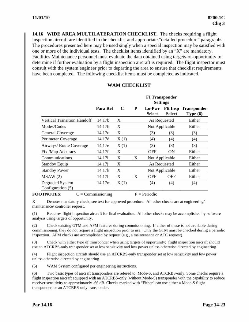
11/01/10 8200.1C Chg 3
Par 14.16 Page 14-23
14.16 WIDE AREA MULTILATERATION CHECKLIST. The checks requiring a flight inspection aircraft are identified in the checklist and appropriate “detailed procedure” paragraphs. The procedures presented here may be used singly when a special inspection may be satisfied with one or more of the individual tests. The checklist items identified by an “X” are mandatory. Facilities Maintenance personnel must evaluate the data obtained using targets-of-opportunity to determine if further evaluation by a flight inspection aircraft is required. The flight inspector must consult with the system engineer prior to departing the area to ensure that checklist requirements have been completed. The following checklist items must be completed as indicated.
WAM CHECKLIST
FI Transponder Settings
Para Ref C P Lo-Pwr Select
Flt Insp Select
Transponder Type (6)
Vertical Transition Handoff 14.17b X As Requested Either
Modes/Codes 14.17h X Not Applicable Either
General Coverage 14.17c X (3) (3) (3) Perimeter Coverage 14.17d X (1) (4) (4) (4)
Airways/ Route Coverage 14.17e X (1) (3) (3) (3) Fix /Map Accuracy 14.17f X OFF ON Either Communications 14.17i X X Not Applicable Either Standby Equip 14.17j X As Requested Either
Standby Power 14.17k X Not Applicable Either
MSAW (2) 14.17l X X OFF OFF Either Degraded System Configuration (5)
14.17m X (1) (4) (4) (4)
FOOTNOTES: C = Commissioning P = Periodic
X Denotes mandatory check; see text for approved procedure. All other checks are at engineering/ maintenance/ controller request.
(1) Requires flight inspection aircraft for final evaluation. All other checks may be accomplished by software analysis using targets of opportunity.
(2) Check existing GTM and APM features during commissioning. If either of these is not available during commissioning, they do not require a flight inspection prior to use. Only the GTM must be checked during a periodic inspection. APM checks are accomplished by request (e.g., a maintenance or ATC request).
(3) Check with either type of transponder when using targets of opportunity; flight inspection aircraft should use an ATCRBS-only transponder set at low sensitivity and low power unless otherwise directed by engineering.
(4) Flight inspection aircraft should use an ATCRBS-only transponder set at low sensitivity and low power unless otherwise directed by engineering.
(5) WAM System configured per engineering instructions.
(6) Two basic types of aircraft transponders are refered to: Mode-S, and ATCRBS-only. Some checks require a flight inspection aircraft equipped with an ATCRBS-only (without Mode-S) transponder with the capability to reduce receiver sensitivity to approximately -66 dB. Checks marked with “Either” can use either a Mode-S flight transponder, or an ATCRBS-only transponder.
8200.1C 11/01/10 Chg 3
Page 14-24 Par 14.17
14.17 WIDE AREA MULTILATERATION DETAILED PROCEDURES
a. General. Facilities Maintenance personnel must use operational displays for target grading and guidance information. Data from the operational displays and automation diagnostic and analysis programs will determine if the system supports operational requirements. When using targets-of-opportunity, multiple target returns are required to ensure accuracy. Verify questionable accuracy with a flight inspection aircraft. The system should be configured for use in the day-to-day standard operating configuration (Normal), except during the Degraded Configuration System checks. During these checks, Facilities Maintenance personnel will configure the WAM system in its lowest usable configuration(s). WAM processes Mode-S and ATCRBS aircraft transponders differently; therefore, some checks are designed to evaluate performance using a specific type of transponder.
b. Vertical Transition Handoff
(1) Purpose. To verify when aircraft transition vertically from the volume of airspace covered by the WAM system to the overlying airspace covered by a conventional radar (ATCRBS), or vice versa, that the transition is seamless with no loss of coverage.
(2) Vertical Transition Area. Choose a ground track between one or more waypoints that transitions through areas of the WAM coverage area where the vertical handoff is to be evaluated.
(3) Approved Procedures. Targets-of-opportunity may be used to check the vertical handoff between WAM and other radars. Verify questionable results with flight inspection aircraft. The flight inspection aircraft should fly the provided ground track and climb and descend through the transition boundary altitude (by at least 1,000 feet) several times.
(4) Evaluation. There should be no loss of coverage when transitioning through the transition boundary altitude.
c. General Coverage
(1) Purpose. To verify designed coverage.
(2) Approved Procedures. Targets-of-opportunity will be the primary method of determining system coverage. Use flight inspection aircraft when there is a lack of data or suspected problem areas. Fly the altitudes and distances requested by engineering personnel.
(3) Evaluation. Facilities Maintenance personnel must determine if the coverage supports operational requirements.

11/01/10 8200.1C Chg 3
Par 14.17d Page 14-25
d. Perimeter Coverage
(1) Purpose. To verify coverage and performance at maximum altitudes and distances.
(2) Approved Procedures. During this check the flight inspection aircraft should utilize the ATCRBS-only transponder operating in the low sensitivity and low power modes (approximately -66 dB and 90 watts). This lower than normal sensitivity approximates the operational limit for a reduction in transmission power from the WAM system ground stations. Engineering may ask to repeat some of this check using the Mode-S transponder (FI Insp Select ON; Lo-Pwr Select ON at or below 15,000’MSL). Fly the perimeter of the constellation adjusting altitude to follow the highest adapted altitude. Fly 100’ below the adapted altitude to prevent unnecessary coverage dropouts due to momentarily exceeding the top altitude. If the terrain elevation becomes a factor while flying the perimeter, adjust the ground track towards the inside of the coverage area while maintaining the desired MSL altitude. Repeat for each constellation if there is more than one. Record time-stamped positioning data for post-flight analysis by engineering personnel.
(3) Evaluation. Facilities Maintenance personnel must determine if the coverage supports operational requirements.
e. Airway/ Route Coverage
(1) Purpose: To document coverage along routes and airways, required by AT. Facilities Maintenance personnel must determine the extent of these evaluations which determine the overall WAM facility coverage. Areas of poor target returns, or other potential problems identified in the inspection plan may be further evaluated to determine actual facility coverage. This check must be accomplished using targets-of-opportunity with the final commissioning check done with a flight inspection aircraft.
(2) Approved Procedures
(a) Inspecting Routes and Airways. During this check the flight inspection aircraft should utilize the ATCRBS-only transponder operating in the low sensitivity and low power modes (approximately -66 dB and 90 watts). This lower than normal sensitivity approximates the tolerance limit for a reduction in transmission power from the WAM system ground stations. Engineering may ask to repeat some of this check using the Mode-S transponder (FI Insp Select ON; Lo-Pwr Select ON at or below 15,000’MSL). The altitudes at which satisfactory coverage exists will be determined by flying the minimum altitude (not lower than MOCA) on airway centerline. The terminal arrival and departure routes and other areas of interest identified in the inspection plan will be flown at MOCA. Maintain course guidance by reference to AFIS, ground checkpoints, NAVAID signals, or radar vectors. Be prepared to provide time-stamped positioning data for post-flight analysis if requested.
8200.1C 11/01/10 Chg 3
Page 14-26 Par 14.17e
(b) Targets-of-Opportunity. Targets may consist of one or an assortment of aircraft returns on a particular airway, route or terminal radial. Targets must show altitude. Scoring may be accomplished by either software tools or manually. Software analysis tools may be used to evaluate the track information of a selected (beacon code) target.
(3) Evaluation. Facilities Maintenance personnel must determine if the facility coverage meets operational requirements.
f. Fix/ Map Accuracy
(1) Purpose. To verify all airways, routes, fixes, and runway centerlines on the video map display. Replacement map overlays, video maps, or digitally-generated maps do not require a flight inspection if Facilities Maintenance personnel can determine, using targets-of-opportunity, that the new map is accurate.
(2) Approved Procedure. If requested, fly the minimum altitude where satisfactory coverage exists along the airway, route, or fix. The procedure is the same whether using a flight inspection aircraft or targets-of-opportunity; Facilities Maintenance personnel compare reported aircraft position relative to the airway, route, or fix with the video map presentation. Similarly, verify runway centerline to video map alignment by observing landing and departing aircraft.
(3) Evaluation. Compute the distance between the airway, route or fix, and the aircraft position, and apply the appropriate tolerance.
(4) Radar Overlays. Flight inspection of radar map overlays used as a backup for a video map need not be accomplished, provided the overlay contains data which is identical to a video map display which has been satisfactorily inspected. Any data on an overlay that differs from the video map display must be inspected before use. This applies to new or replacement map overlays.
g. Surveillance Approaches. WAM does not provide approach service at this time.
h. Modes and Codes
(1) Purpose: To verify the proper decoding of ATCRBS reply pulses and altitude readout. Codes 7500, 7600, and 7700 should not be used without comprehensive prior coordination due to the possibility of alarming other facilities.
(2) Approved Procedure. Facilities Maintenance personnel must monitor the flight inspection aircraft transponder replies or targets-of-opportunity throughout the vertical coverage, airway, route, and terminal checks to verify correct altitude readout. During these tests, Facilities Maintenance personnel should request the flight inspection aircraft use different modes or codes to sample various modes and code trains. When targets-of-opportunity are used, ensure that the sample contains all modes interrogated and a sufficiently large sample of codes to ensure correct decoding of beacon replies.

11/01/10 8200.1C Chg 3
Par 14.17h Page 14-27
(3) Evaluation. Facilities Maintenance personnel must ensure the displayed transponder reading agrees with the aircraft transponder setting and altitude.
i. Communications. The purpose of this check is to evaluate VHF/ UHF communications capability within the coverage area. When flight inspection aircraft are not equipped for UHF communications, the inspection can be completed using VHF only. UHF coverage may be confirmed by the appropriate air traffic facility via targets of opportunity. The flight inspector must check communications in accordance with Chapter 8, concurrent with the WAM inspection.
j. Standby Equipment. The purpose of this check is to evaluate the performance of standby equipment, and may be accomplished during pre-inspection testing using targets-of-opportunity. A WAM system normally has two Target Processors (TP1 and TP2). Attempt to document the performance of both during the commissioning flight inspection.
k. Standby Power. The purpose of this check is to evaluate system performance on standby (engine generator) power and must be conducted during pre-inspection testing.
l. Minimum Safe Altitude Warning (MSAW). Follow guidance in Paragraph 14.14t.
m. Degraded System Configuration.
(1) Purpose: To verify that the system performs in an acceptable manner, with adequate coverage and position accuracy, in the allowable degraded states..
(2) Approved Procedure.
(a) During each of these checks, the flight inspection aircraft will record time-stamped positioning data for post-flight analysis by engineering personnel. Unless otherwise requested by engineering, the flight inspection aircraft should utilize the ATCRBS-only flight inspection transponder, (i.e., without Mode S), operating in the low sensitivity and low power mode (approximately -66 dB and 90 watts).
(b) N-1 State Check. A WAM system is normally designed to operate in a “N-1” state, with one of the Receive Only (RO) or Receive/Transmit (RT) Remote Units (RUs) out of service.
NOTE: Some WAM systems may not be designed to operate in an N-1 configuration, and some may be designed to operate in an even more (e.g., N-2) degraded configuration. Adapt this check accordingly to the given situation.
8200.1C 11/01/10 Chg 3
Page 14-28 Par 14.17m
Prior to the flight inspection, engineering personnel will determine, using software analysis tools, which RUs, when disabled result in possible marginal coverage, and/or marginal performance (positional accuracy). In addition, a specific routing (ground track and altitudes) will be identified in the inspection plan to be flown with each marginal “N-1” state. Also fly an instrument procedure final segment and missed approach segment (if available) to any runways within the area identified as an area of possible marginal coverage/ performance. This doesn’t require flying every published approach and missed approach procedure to every runway within the possible marginal area. Choosing a representative approach and missed approach will suffice. If warranted and circling is authorized for any instrument approach procedure at the airport, consideration should be given to circling around the airport in question at the minimum circling altitude. If more than one inoperative RU (“N-1”) state is identified, configure the system in each “N-1” state in turn, and fly the associated routing/ approaches with each.
(c) Horizontal Transitions. Conduct this check at the request of Engineering Services only. Configure the WAM system per engineering direction. Fly any airway or ATC routing from outside the WAM system coverage area, through the WAM area, and back out of coverage, all at 100 feet below the maximum altitude(s). Maximum altitude in this case is defined as the highest altitude within a given sort box at which WAM coverage will be utilized by Air Traffic. Flying 100 feet below the designed altitude should prevent unnecessary coverage drop-outs due to momentarily exceeding the software controlled cut-off altitude. Note that this check will require configuring the automation display to include neighboring radars as well as the WAM coverage area.
(3) Evaluation. In addition to real-time assessment of system performance and coverage, conduct a post-flight analysis of the flight inspection positioning data to determine system accuracy. Facilities Maintenance personnel must determine if the facility performance meets operational requirements. 14.18 ANALYSIS
a. Testing Precautions. Radar inspections should not be attempted during heavy precipitation, temperature inversions, or other atmospheric conditions which change the coverage from normal. Whenever a system parameter does not meet tolerances and cannot be adjusted within a reasonable length of time, discontinue the flight inspection until the discrepancy is resolved. This does not preclude the continuation of tests in an effort to resolve the problems.
b. Evaluation. Usable radar coverage does not mean a usable target return on every scan at every azimuth and all usable altitudes. Missed targets can be caused by antenna lobing, line-of-sight, aircraft attitude, or antenna tilt. Therefore, isolated or non-recurring target misses are to be expected. If three or more consecutive misses are experienced, determine if a hole exists in the radiation pattern and determine its size. If holes or poor coverage are discovered, they must be evaluated to determine the effect on the operational requirements.
11/01/10 8200.1C Chg 3
Par 14.18c Page 14-29
c. Probing. Holes in radar coverage are probed in a manner similar to VOR to TACAN. The following procedure may be used as a guide:
(1) Horizontal. Fly through the area of the suspected hole to determine the inner and outer boundaries. Vary the aircraft position every 10 of radar azimuth until the lateral limits are established.
(2) Vertical. Fly through the center of the pattern established in the horizontal probing procedure at 1,000-foot increments to determine the upper and lower limits of the hole.

8200.1C 11/01/10 Chg 3
Page 14-30 Par 14.19
14.19 TOLERANCES Figure 14-5
TOLERANCES
Parameter Reference Tolerance/Limit
Target Strengths Broadband/Reconstituted 3—usable Target leaves trail or persists from scan-to-scan
without trail. 2—usable Target shows each scan, remains on the display
for at least 1/3 of the scan. 1—unusable Weak target, barely visible, possible miss. 0—unusable No visible target. Narrowband 1—usable Visible target, satisfactory for ATC purposes. 0—unusable No visible target, unsatisfactory for ATC. Usable Target Target which is not missed/ unusable on three or
more consecutive scans. Orientation Maximum azimuth difference between actual and indicated for broadband and narrowband radar systems.
14.14d 20
Tilt 14.14e No airborne tolerance. Coverage Vertical - from inner to outer fringe 14.14g Meets operational requirements at all altitudes. Horizontal 14.14h No tolerance. Vertical Tansition Handoff (WAM) 14.17b No loss of coverage during transition General Coverage (WAM) 14.17c Meets operational requirements Perimeter Coverage (WAM) 14.17d Meets operational requirements Approaches, airways, arrival and departure routes, and fixes route/ procedure
14.14i 14.17e
A usable target return must be maintained along the entire route or throughout the procedure.
Accuracy (1), (2) Fix/map 14.14j
14.17f Within 3% of aircraft to antenna distance or 500’ (1,000’ for ATCRBS), whichever is greater. 500’ for WAM systems, regardless of aircraft position.
Approaches 14.14k Straight-in Within 500’ of runway edge at MAP. Circling Within a radius of the MAP which is 3% of the
aircraft to the antenna distance or 500’, whichever is greater.
Altitude Readout 14.14n 14.17h
125’ of altitude displayed in the cockpit relative to 29.92 in Hg.
(1) 3% exceeds 500 ft at aircraft to antenna distance greater than 16,667 ft (2.74 nm).
(2) 3% exceeds 1,000 ft (ATCRBS) at aircraft to antenna distance greater than 33,333 ft (5.49 nm).
11/01/10 8200.1C Chg 3
Par 14.19 Page 14-31
Parameter Reference Tolerance/Limit Communications Chapter 8 See Paragraph 8.14 Standby Equipment 14.14r
14.17j Meet same tolerances as main (dual channel) equipment. See Paragraph 4.33b.
Standby Power 14.14s 14.17k
See Paragraph 4.33c.
14.20 DOCUMENTATION. The AF regional office of concern, or military equivalent, will compile and complete the facility inspection performance report. It will be a detailed accounting of all coverage data obtained using ground testing data, flight inspection aircraft, targets-of-opportunity, RDAS tools, and all flight inspection report information. The report submitted by the flight inspector must contain only that information evaluated by the flight inspection crew. At joint use sites, a separate report will be published, under the direction of Air Combat Command and North American Aerospace Defense Command. 14.21 FACILITY CLASSIFICATION. The facility inspection performance report must reflect a facility classification determined by the facility engineer in charge (or military equivalent). The flight inspection report must reflect a facility classification jointly determined by the flight inspector and Facilities Maintenance personnel. Inaccuracies beyond established tolerances in range and azimuth for fix/ map targets or surveillance approaches will be the basis for the flight inspector to restrict the system or to request that it be removed from service until the condition is corrected.
SECTION 2. PRECISION APPROACH RADAR (PAR)
14.22 INTRODUCTION
a. This section provides instructions and performance criteria for certifying precision approach radars. The PAR is designed to provide an approach path for precise alignment and descent guidance to an aircraft on final approach to a specific runway through interpretation and oral instructions of a ground based controller.
b. PAR(s) provide a very high degree of resolution in terms of range, azimuth and elevation by radiating a narrow pulse and beam width. The pulsed beams are radiated along the predetermined descent path for an approximate range of 10 to 20 miles, and covers a sector of 20 in azimuth and up to 15 in elevation. Target information is displayed on an azimuth and elevation display. The displays must provide accurate information regarding an aircraft's range, azimuth, and elevation angle.

8200.1C 11/01/10 Chg 3
Page 14-32 Par 14.23
14.23 PREFLIGHT REQUIREMENTS
a. Facilities Maintenance Personnel. Prepare for flight inspection in accordance with the procedures outlined in Chapter 4.
b. Flight Personnel. The flight inspector will be in complete charge of the flight inspection. Flight personnel will prepare for the inspection in accordance with the procedure outlined in Chapter 4.
c. Special Equipment Requirements. PAR glide slope angle will be determined by AFIS, unless theodolite method is applied or the inspection is conducted in accordance with the requirements of a Military Contingency or Natural Disaster as described in Chapter 24. Aircraft with altimeters calibrated according to FAR 43, Appendix E, and FAR 91.170, or military specifications, may be used for PAR flight checks. Theodolite or AFIS is required as follows:
(1) During commissioning and/or after accident inspection of the glidepath angle and the lower safe angle.
(2) Any time that more definitive analysis is required (e.g., engineering, research, development) of either the glidepath or the course azimuth.
d. Theodolite Procedures. The RTT or theodolite will be positioned as follows:
(1) Glidepath Angle
(a) Place the theodolite as close to the runway as possible, forward of the RPI, to minimize or eliminate elevation differences between RPI (touchdown) and theodolite locations. The touchdown reflector is usually abeam the RPI, but not always. Therefore, the Facility Data Sheet must be checked to establish the exact RPI location. Aircraft operations will dictate how close to the runway the theodolite can be located.
NOTE: During the commissioning inspection of a new or relocated PAR, it is imperative that flight inspection personnel coordinate closely with the procedures specialist and installation personnel to locate the predetermined RPI.
(b) The distance the theodolite must be moved forward of the RPI to have the eye-piece aligned on the glidepath angle can be computed in the same manner as solving for ILS glidepath angles or tapeline altitudes. For example, a theodolite with the eye-piece set at 5 ft at a glidepath angle of 3.0 would be positioned 95.4 ft forward of the RPI.
(2) Lower Safe Angle
(a) If the lower safe angle emanates from the same RPI as the glidepath, the theodolite position will be the position determined for the glidepath.
11/01/10 8200.1C Chg 3
Par 14.23 Page 14-33
(b) If the lower safe angle emanates from a point other than the RPI for the glidepath, the theodolite will be relocated. Position and align the theodolite in accordance with instructions for glidepath angle using the lower safe angle RPI.
(3) Course Alignment. Position the theodolite on runway centerline to evaluate course alignment at the runway threshold. Aircraft operations will dictate theodolite placement. 14.24 FLIGHT INSPECTION SPECIFICATIONS. The flight inspection procedure for a PAR is divided into three parts:
a. Azimuth radar
b. Elevation radar
c. Overall system and controller performance (includes feature comparisons).
Commissioning inspections will provide engineering, maintenance, and operations personnel with sufficient data to determine system performance. Data obtained from the commissioning inspection will be the basis for the comparison of facility performance on subsequent inspections. Requirements for special checks will be determined by engineering, maintenance, and operations personnel, and will be conducted as specified in Chapter 4. Flight inspection is required following an antenna change, change to the glide path angle, changes to reference (alignment) reflector height or placement, changes to cursor alignment voltages or settings, and any other action which will change the azimuth or elevation alignment. 14.25 CHECKLISTS. The checklists below are to be used for the identified equipment. If the equipment to be inspected is different, the basic requirements for a "generic" PAR must be used and additional runs performed to check any special features specified by facility engineering or operations. At locations where approaches to more than one runway are provided, checks will be accomplished for each runway on commissioning inspections. Periodicity of checks must be accomplished in accordance with Chapter 4, alternating runways, assuring that all runways/ SIAP(s) that are associated with the PAR system are checked at least once each 540 days. The periodic must be considered complete each time the periodic checklist is complete and the Chapter 6 SIAP check is accomplished for the runway being inspected.
Legend for Checklists
AC - Antenna Change B Cursor - The cursor defining the lower safe limit
DBC - Database Change (may be software or firmware
A Cursor - The cursor defining the normal glide angle
C - Commissioning P - Periodic
ALS - Automatic Landing Subsystem
CFAR - Constant False Alarm Rate

8200.1C 5/30/11 Chg 4
Page 14-34 Par 14.25a
a. GENERIC PAR (FPN-40, FPN-62/ 63, MPN-14, TPN-18, TPN-44)
This family of radar is characterized by mechanically scanned (moving) azimuth and elevation antennas. Displayed targets are not computer enhanced. The PAR may be part of a larger system containing an ASR.
Type Check
Reference
Paragraph Inspection CU
RS
OR
Measurements Required
Alignment
C
AC
AZ
(3)
AC
E
L (
3)
P
Cu
rsor
Ob
stac
le C
lear
ance
Cov
erag
e
Ran
ge A
ccu
racy
MT
I /M
TD
An
gle
Coi
nci
den
ce
AZ
GP
Dev
iati
on A
ccu
racy
CP
/ LP
Approach #1 14.26a 14.26h
X X X X A X X X X X X X X X
Approach #2 14.26a 14.26k
X X X X B X X
Lateral
Coverage
14.26f (1) (1) (1) A X X
Azimuth Only
14.26b X X X X (4)
Standby (2)
Transmitter
14.26n X
X
X
X
X
A
B
X
X
X
X X X X X
Standby
Power
14.26o 4.33c
X A X X
Alternate
Angle
14.26h X X A X X
Lights 14.26l Chapter 7
X X X
Comm 14.26m X X X
(1) Maintenance request
(2) For generic (non-computer generated) PAR(s), inspect both the A and B Cursors when checking the standby transmitter.
(3) Apply commissioning tolerances when conducting a special inspection for antenna change (AZ or EL).
(4) Measure alignment at threshold.
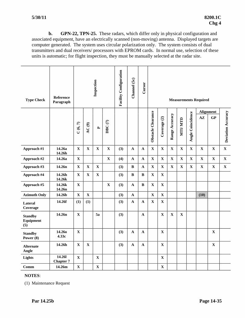
5/30/11 8200.1C Chg 4
Par 14.25b Page 14-35
b. GPN-22, TPN-25. These radars, which differ only in physical configuration and associated equipment, have an electrically scanned (non-moving) antenna. Displayed targets are computer generated. The system uses circular polarization only. The system consists of dual transmitters and dual receivers/ processors with EPROM cards. In normal use, selection of these units is automatic; for flight inspection, they must be manually selected at the radar site.
Type Check Reference Paragraph
Insp
ecti
on
Fac
ilit
y C
onfi
gura
tion
Ch
ann
el (
5c)
Cu
rsor
Measurements Required
Alignment
C (
6, 7
)
AC
(9)
P
DB
C (
7)
Ob
stac
le C
lear
ance
Cov
erag
e (2
)
Ran
ge A
ccu
racy
MT
I/ M
TD
An
gle
Coi
nci
den
ce
AZ GP
Dev
iati
on A
ccu
racy
Approach #1 14.26a 14.26h
X X X X (3) A A X X X X X X X X
Approach #2 14.26a X X (4) A A X X X X X X X X
Approach #3 14.26n X X X (3) B A X X X X X X X X
Approach #4 14.26h 14.26k
X X X (3) B B X X
Approach #5 14.26k 14.26n
X X (3) A B X X
Azimuth Only 14.26b X X (3) A X X (10)
Lateral Coverage
14.26f (1) (1) (3) A A X X
Standby Equipment (5)
14.26n X 5a (3) A X X X
Standby Power (8)
14.26o 4.33c
X (3) A A X X
Alternate Angle
14.26h X X (3) A A X X
Lights 14.26l Chapter 7
X X X
Comm 14.26m X X X
NOTES:
(1) Maintenance Request

8200.1C 5/30/11 Chg 4
Page 14-36 Par 14.25b
(2) Normal Coverage is 20 nm. Establish coverage limits during commissioning (or at maintenance request) by flying a 20-mile final approach; thereafter, controller/ maintenance personnel must monitor coverage on a daily basis using targets of opportunity.
(3) Track Mode - NORMAL Close Control FTC-ON MTI - COHERENT
(4) Track Mode - BACKUP (Scan Only at MR) FTC-OFF MTI-NON-COHERENT
(5) Commissioning requirements for standby equipment (consisting of a complete separate channel) can be completed by flying Runs 1, 2, and 5 to any one of the runways served. If standby equipment is only a separate transmitter, fly Run 1 from 20 nm to satisfy commissioning requirements.
(a) Check both receivers/ processors during a periodic check.
(b) It is only necessary to check the operating radar transmitter and database during a periodic check. However, attempt to alternate which transmitter is checked from periodic to periodic inspection.
(c) A-Channel/ B-Channel refers to which receiver/ processor is on-line.
C P Radar Receivers/Processors X X (5a) Radar Transmitters X X (5b) Database X X (5b)
(6) Parallel Runways. If one reference reflector and a common glidepath angle are used for parallel runways, only 5 runs are required for commissioning. Fly approaches # 1,# 2, and #3 on the left runway, #4 and #5 on the right runway and reverse the order for the opposite end. If each runway has a separate reference reflector and/or angle, fly approaches #1,# 2, and #3 on the left runway, #1, #4, and #5 on the right runway and reverse the order for the opposite end.
(7) Each database version requires a flight inspection prior to operational use in order to verify that the database data can be loaded into the PAR computer and that the data produces the correct results. Documentation required for commissioning and equipment/ database changes:
(a) Transmitter Power
(b) Receiver sensitivity in normal, Coherent MTI, and Non-Coherent MTI
(c) Firmware Version Numbers
(d) Clutter reject setting (if required for approaches).
(e) Digital MTI baseline limiting settings
(f) Usable radar range on 20 nm radar
(8) Evaluate the operation on standby power during any of Runs 1, 3, 4, or 5.
(9) Apply commissioning tolerances when conducting a special inspection for antenna change. These types of PAR(s) do not have separate AZ and EL antennas.
(10) Measure alignment at threshold.
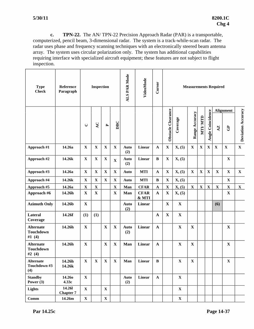
5/30/11 8200.1C Chg 4
Par 14.25c Page 14-37
c. TPN-22. The AN/ TPN-22 Precision Approach Radar (PAR) is a transportable, computerized, pencil beam, 3-dimensional radar. The system is a track-while-scan radar. The radar uses phase and frequency scanning techniques with an electronically steered beam antenna array. The system uses circular polarization only. The system has additional capabilities requiring interface with specialized aircraft equipment; these features are not subject to flight inspection.
Type Check
Reference Paragraph
Inspection
AL
S P
AR
Mod
e
Vid
eoM
ode
Cu
rsor
Measurements Required
Alignment
C
AC
P
DB
C
Ob
stac
le C
lear
ance
Cov
erag
e
Ran
ge A
ccu
racy
MT
I/ M
TD
An
gle
Coi
nci
den
ce
AZ
GP
Dev
iati
on A
ccu
racy
Approach #1 14.26a X X X X Auto (2)
Linear A X X, (5) X X X X X X
Approach #2 14.26k X X X X Auto (2)
Linear B X X, (5) X
Approach #3 14.26a X X X X Auto MTI A X X, (5) X X X X X X
Approach #4 14.26k X X X X Auto MTI B X X, (5) X
Approach #5 14.26a X X X Man CFAR A X X, (5) X X X X X X
Approach #6 14.26h X X X Man CFAR & MTI
A X X, (5) X
Azimuth Only 14.26b X Auto (2)
Linear X X (6)
Lateral Coverage
14.26f (1) (1) A X X
Alternate Touchdown #1 (4)
14.26h X X X Auto (2)
Linear A X X X
Alternate Touchdown #2 (4)
14.26h X X X Man Linear A X X X
Alternate Touchdown #3 (4)
14.26h 14.26k
X X X X Man Linear B X X X
Standby Power (3)
14.26o 4.33c
X Auto (2)
Linear A X
Lights 14.26l Chapter 7
X X X
Comm 14.26m X X X

8200.1C 5/30/11 Chg 4
Page 14-38 Par 14.25c
NOTES: (1) Maintenance request.
(2) A periodic check must be considered complete if Auto-Mode is inoperative. Note the condition on the flight inspection report. The PAR must be considered as "Restricted" and authorized for use in Manual-Mode only.
(3) IF EQUIPPED, standby power should be performed on the last run due to the extensive time required to reload the software and data.
(4) Alternate touch down (TD) points using the same glide angle may be available.
(5) Request usable distance from controller on each approach.
(6) Measure alignment at threshold.
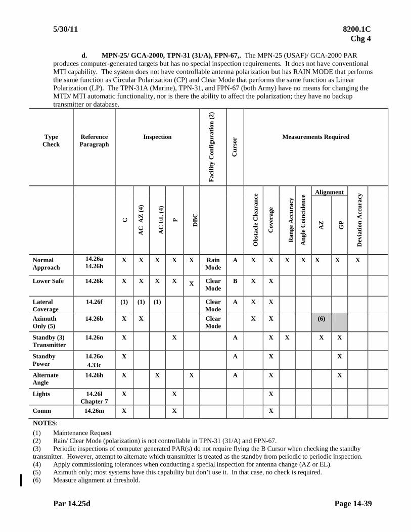
5/30/11 8200.1C Chg 4
Par 14.25d Page 14-39
d. MPN-25/ GCA-2000, TPN-31 (31/A), FPN-67,. The MPN-25 (USAF)/ GCA-2000 PAR produces computer-generated targets but has no special inspection requirements. It does not have conventional MTI capability. The system does not have controllable antenna polarization but has RAIN MODE that performs the same function as Circular Polarization (CP) and Clear Mode that performs the same function as Linear Polarization (LP). The TPN-31A (Marine), TPN-31, and FPN-67 (both Army) have no means for changing the MTD/ MTI automatic functionality, nor is there the ability to affect the polarization; they have no backup transmitter or database.
Type Check
Reference Paragraph
Inspection
Fac
ilit
y C
onfi
gura
tion
(2)
Cu
rsor
Measurements Required
Alignment
C
AC
AZ
(4)
AC
EL
(4)
P
DB
C
Ob
stac
le C
lear
ance
Cov
erag
e
Ran
ge A
ccu
racy
An
gle
Coi
nci
den
ce
AZ
GP
Dev
iati
on A
ccu
racy
Normal Approach
14.26a 14.26h
X X X X X Rain Mode
A X X X X X X X
Lower Safe 14.26k X X X X X Clear Mode
B X X
Lateral Coverage
14.26f (1) (1) (1) Clear Mode
A X X
Azimuth Only (5)
14.26b X X Clear Mode
X X (6)
Standby (3) Transmitter
14.26n X X A X X X X
Standby Power
14.26o 4.33c
X A X X
Alternate Angle
14.26h X X X A X X
Lights 14.26l Chapter 7
X X X
Comm 14.26m X X X
NOTES:
(1) Maintenance Request (2) Rain/ Clear Mode (polarization) is not controllable in TPN-31 (31/A) and FPN-67. (3) Periodic inspections of computer generated PAR(s) do not require flying the B Cursor when checking the standby transmitter. However, attempt to alternate which transmitter is treated as the standby from periodic to periodic inspection. (4) Apply commissioning tolerances when conducting a special inspection for antenna change (AZ or EL). (5) Azimuth only; most systems have this capability but don’t use it. In that case, no check is required. (6) Measure alignment at threshold.
8200.1C 11/01/10 Chg 3
Page 14-40 Par 14.26
14.26 FLIGHT INSPECTION PROCEDURES. The basic method for checking a PAR is to have the controller vector the aircraft and provide guidance instructions to the flight inspector for evaluation of the facility.
Maintenance/ Engineering Personnel, in cooperation with operations personnel, will spot check all features available on the PAR and advise the flight inspector if any of these features are not available or are unusable. These features include STC, FTC, CP, and CFAR. On computer-generated radars, additional features include: non-coherent MTI (rain reject), ACQ (high and low), track mode (normal and backup), STC (high and low), and power (high and low). PAR checks will be made using circular polarization (CP) if available, and spot checks of the facility will be made using linear polarization. On some computer-generated radars, CP is a fixed feature and is used at all times.
Operational scopes will be used on all flight checks for target grading and guidance information. Data taken from the operational scopes must determine whether or not the facility meets the prescribed tolerances.
Suitability and approval of approach procedures previously developed by the procedures specialist are based on the flight check of the particular facility.
a. Course Alignment and Coverage (Azimuth). Any of the following methods may be used:
(1) AFIS Method. This is the preferred method. Use the procedures in the appropriate AFIS equipment handbook.
(2) Visual Method. To check for course alignment, proceed in-bound at pattern/ intercept altitude from approximately 10 to 12 miles from the runway and, when on-course and path, descend at a normal glidepath angle with the final controller furnishing information to enable the flight inspector to fly on the centerline azimuth. This information is to be given as "left," "right," or "on-course." Range should be given at least every mile. The flight inspector will determine, by visual reference to the runway, if the centerline is straight and if it coincides with the runway centerline extended.
(3) Theodolite Method. At some locations, it may be necessary to use a theodolite to supplement the pilot's observations, especially when the runway is extremely wide or poorly defined by surrounding terrain. Proceed in-bound at pattern/ intercept altitude from 10 to 12 miles from the field. Have the final controller furnish information as to the aircraft's position relative to runway centerline. The theodolite operator will continuously track the aircraft and inform the pilot of the aircraft position relative to runway centerline.
(4) Course alignment is most critical at touchdown. Ensure the alignment is satisfactory at runway threshold using AFIS, visual means, or theodolite. Along-track azimuth alignment at distances greater than threshold must be determined when AFIS measurement techniques are used. Apply the along-track tolerance to the average of all on-course calls. Discuss any singular along-track errors with Air Traffic and/or PAR maintenance personnel for resolution.
11/01/10 8200.1C Chg 3
Par 14.26b Page 14-41
b. Azimuth Only Procedures. Some facilities have “AZ ONLY” or “PAR w/o GS” procedures published for use during outages of the elevation portion. Procedurally, the obstacle clearance area of the PAR is used and non-precision Required Obstacle Clearance (ROC) applied. An “AZ ONLY” approach may therefore have a lower MDA than an ASR approach to the same runway because the ASR obstacle clearance area is larger and may contain higher obstacles. For a PAR with “w/o GS” procedure, the procedural altitudes must be maintained in all but the final segment. For the final segment, upon reaching the FAF inbound, descend at a rate of approximately 400 ft per mile to an altitude of 100 ft below the lowest MDA and maintain this altitude to the threshold. Ensure radar coverage and obstacle clearance. Alignment should be measured at threshold; this requirement may be satisfied during the normal PAR approach.
c. Course Deviation Accuracy. While flying inbound on runway centerline extended, deviations to the right or left of centerline should be made with attention directed as to how far the aircraft must move off centerline before the controller notices movement. The controller needs only to state - slightly left (or right) of centerline.
d. Range Accuracy. Check the accuracy of the range information, both video and fixed, by comparison with the AFIS or DME. Checkpoints such as the outer marker or VOR are excellent; however, any well surveyed checkpoint is satisfactory, provided its distance from the field can be established. All ranges are measured in nautical miles from touchdown. In areas where there are no ground checkpoints or good electronic means of accurately measuring distance from the field, such as DME, this check may be omitted. Normally, two checkpoints, one at 5 to 10 miles and one at 1/2 mile, are sufficient for checking range accuracy. Range accuracy checks of azimuth and elevation radar normally will be made simultaneously. (See Paragraph 14.24e, Note.)
e. Usable Distance. The check for usable distance or maximum range, may be made while proceeding in-bound from the limit of the radar coverage during the course alignment check by having the controller give the mileage when the aircraft is first displayed. The new radars have ranges of 15 to 20 miles, but because of small aircraft size, less coverage can be expected. Azimuth and elevation coverage can be checked simultaneously. Coverage of those PAR(s) which have coverage capabilities beyond 10 nm should be checked at the minimum vectoring altitude to the coverage capabilities of the radar. Coverage should be checked using alternately normal and MTI radar. Periodic coverage checks need to be made only in the area of operational use.
NOTE: Mileage information given by the radar operator should be the mileage from the touchdown point to the target aircraft. In case erroneous mileage information is given, the flight inspector should inquire if the range information obtained from the scope has been corrected to compensate for the distance from the antenna to the RPI (touch-down point).
f. Coverage (Lateral). The lateral coverage of the PAR may be determined by
flying perpendicular to the course. Lateral position of the aircraft must be determined by AFIS, theodolite, or large scale map. Altitude and distance will be determined by engineering/ maintenance personnel. The controller will indicate when he/ she obtains and loses radar contact.
8200.1C 11/01/10 Chg 3
Page 14-42 Par 14.26g
g. Moving Target Indicator (MTI)/ Moving Target Detector (MTD). Blind speeds for PAR systems are usually quite high due to the high pulse repetition frequency (PRF) required for good target definition. It may be quite difficult to perform an MTI/ MTD check with certain types of small aircraft due to speed limitations. This check can be omitted if the speed range required is impossible to attain. The check can be performed at a later date when a faster aircraft is available. An airspeed notch of as much as 20 knots may exist around the computed blind speed.
(1) During the commissioning inspection, the MTI/ MTD feature will be checked to determine if there are any blind speeds at which it is impossible to maintain continuous radar contact. On subsequent inspections, MTI/ MTD needs to be checked only when requested by maintenance or operations. Maintenance personnel will provide the precomputed blind speed for the radar. Determine the airspeed which will give the required ground speed. Fly in-bound from approximately 10 miles (ensure that MTI is gated beyond 10 miles) while varying the air speed slightly above and below the previously computed airspeed. Note the speed range within which a reduction of target brilliance occurs. Close coordination between the controller and the flight inspector is necessary to determine the speed at which MTI/ MTD causes the greatest effect.
(2) When MTI/ MTD is required on the final approach, this information must be noted on the flight inspection report. The requirements for MTI do not constitute a facility restriction. Both azimuth and elevation MTI/ MTD normally will be checked at the same time.
(3) On radars with computer generated displays, the normal mode of operation is to use the synthetically generated symbols for approaches. The normal radar (scan) mode must be checked to determine its usability for approaches. If unusable for approaches, determine the inner limit of usability so that the feature can be used for control and traffic information outside of that point. Document the results of the scan-mode inspection in the Remarks section. If the scan mode is not usable for approaches, it will not cause a facility restriction but must be documented on the Facility Data Sheet.
h. Glidepath Alignment. During the glidepath alignment check, it is necessary to determine the glidepath angle and the straightness of the glidepath centerline. Some new military PAR(s) have the capability to provide controller selected multiple glidepaths. For these radars, all published angles must be inspected prior to use; for periodic inspections, only the lowest angle must be evaluated.
(1) AFIS Methods. PAR glide slope angle will be determined by AFIS, unless theodolite method or Chapter 24 is applied.
(2) Theodolite Method. Position the theodolite according to instructions in Paragraph 14.21d. Communications on a common frequency are essential for the theodolite operator, final controller, and flight inspector. After communications have been established at all three locations, the aircraft should proceed in-bound from a point approximately 12 miles from touchdown and at the pattern altitude until the final controller advises that the aircraft is on the glidepath. A descent is then commenced, maintaining the aircraft as nearly on the centerline or glidepath as possible by using the information furnished by the controller. The pilot should
11/01/10 8200.1C Chg 3
Par 14.26h Page 14-43
maintain as constant an attitude as possible throughout the approach. Information should be given in terms of "above," "below," or "on glidepath." The theodolite operator will track the aircraft from the start of the in-bound run, maintaining the horizontal cross-hair exactly on the aircraft as it descends on the glidepath. As the aircraft proceeds in-bound, the theodolite operator should listen carefully to the glidepath information issued by the controller and have an assistant record the angle each time the controller calls the aircraft "on glidepath." Do not record calls taken inside of decision height. These angle readings should then be averaged to determine the actual glidepath angle.
(3) Precision Range Mark Method. Determination of angle using altimetry is only authorized when inspecting under the provisions of Chapter 24. When it is impractical to check the glidepath alignment using the above methods, it is permissible to use the radar to determine the distance of the aircraft from the touchdown point. Obviously, any range errors present in the PAR will cause a corresponding error when measuring the glide slope angle. When making this check, calculate the altitude for the published/ desired glidepath angle at the 6-, 5-, 4-, 3-, 2-, and 1-mile range marks.
Instruct the PAR controller to give precise "on path" calls and the precise point at which the radar return crosses the range marks. By comparing the actual aircraft altitude at the exact point on glidepath with the calculated altitude, it can be determined that the glidepath is at the published/ desired angle. Although there is a small amount of altimeter lag when proceeding down the glidepath using this method, it is negligible and can be disregarded. The straightness of the glidepath can be ascertained concurrently with the alignment check..
An alternative method is to fly a descending run on the glidepath and note the difference in altitude between range marks. It is necessary that the controller provide range information each time a path call is given. The glidepath angle can then be determined as indicated in the formula in Appendix 2, Paragraph A2.17b, using on-path calls at the measurement points.
i. Application of Angle Tolerances. Prior to the commissioning inspection of PAR(s), operational personnel must determine the "desired" angle to which the PAR is to be commissioned. This angle is determined by obstacle clearance criteria and operational use requirements. The obstacle clearance criteria allows for operational deviation (periodic angle tolerance) of 0.2 from the commissioned angle. It is imperative that the reported commissioned angle be the angle for which obstacle clearance and operational criteria has been applied. The desired angle, the computed angle, and the commissioned angle are actually the same.
The allowable periodic deviation of 0.2 is applied to the desired/ computed angle and not the angle found during commissioning inspections. Because the periodic tolerance of 0.2 is applied to the commissioned angle, operations/ maintenance personnel must determine the acceptability of a facility which will require the application of an imbalanced periodic tolerance. An example of this situation is as follows: Desired/ commissioned angle = 3.00, angle found during commissioning = 2.90, allowable deviation = 3.00 .2 or 2.8 to 3.2.

8200.1C 11/01/10 Chg 3
Page 14-44 Par 14.26j
j. PAR Coincidence with Other Guidance. Coincidence of the azimuths and glidepaths of the PAR and ILS/ MLS/ VGSI is essential to preclude pilot confusion from different indications of the ILS/ MLS/ VGSI and PAR. Coincidence may be checked using the AFIS, theodolite, precision range mark procedure, or a microamp comparison with the ILS/ MLS/ VGSI. If any doubt exists as to glide angle coincidence, the theodolite or AFIS must be used. Perform a PAR approach as directed by the final controller and monitor the approach using the ILS/ MLS/ VGSI. Coincidence probably will not be maintained from Point "B" to touchdown due to the characteristics of the ILS glide slope inside Point "B." Areas of non-coincidence of the azimuths and glidepaths should be noted.
k. Lower Safe Limit Alignment. The lower safe limit must be checked as follows:
(1) Fly in-bound 5 to 7 miles from the runway on the lower safe limit line and maintain "on-path" at the controller's direction. Maintain "on path" position to the runway, or until it becomes obvious that a pull-up is necessary to avoid obstacles. By flying the lower safe limit line, the aircraft should clear all obstacles prior to passing the runway threshold.
(2) Scopes which do not have the lower safe limit line portrayed must be checked in the same manner as above. The controller will supply information to the flight inspector so that he can fly the lower safe limit altitudes (below which a missed approach would be necessary), and be clear of obstacles prior to passing the runway threshold.
The lower safe limit angle is normally 0.5 less than the glidepath angle. During the commissioning flight checks, the lower safe limit angle must be established in the same manner as the glide slope angle (see Paragraph 14.24h). Verification of the angle on subsequent checks is not necessary unless requested by maintenance; all that is required is that satisfactory obstacle clearance is provided while flying the lower safe limit line/ altitude as described above.
l. Lighting Systems. Lights must be inspected in accordance with applicable chapters of this manual.
m. Communications. During commissioning inspections, check all required frequencies from the final controller position. When flight inspection aircraft are not equipped for UHF communications, the inspection can be completed using VHF only. UHF coverage may be confirmed by an operational check of the PAR using local aircraft. Evaluate both primary and standby radios for clarity and coverage. These checks may be done within or beyond the radar service area.
n. Standby Equipment. Checklists in Paragraph 4.33 specify the minimum checks for the standby equipment, if installed. For periodic inspections, review the previous report and attempt to perform the primary equipment checks on the equipment used as standby on the previous inspection. The standby equipment will be checked to ensure that it is functioning in a manner equal to the primary equipment.
o. Standby Power. Standby power must be inspected in accordance with Paragraph 4.33c of this manual. Standby power can be checked on any approach required by the Paragraph 14.23 Checklist. It is not necessary to duplicate a run solely to check standby power.
5/30/11 8200.1C Chg 4
Par 14.27 Page 14-45
14.27 ANALYSIS. A flight inspection of a ground radar facility always uses the services of the ground controllers, maintenance, and/or engineering personnel because of the inherent and unique characteristics of the entire system.
The flight inspector is responsible for determining that the PAR conforms to the specified tolerances. Any discrepancies found which could be attributable to controller technique should be brought to the attention of the ground supervisory personnel. 14.28 TOLERANCES. All precision approach radars must meet the tolerances set forth below for an unrestricted classification. Classification of the facility based on flight inspection results is the responsibility of the flight inspector.
INSPECTION PARAMETER REF. PARA. C P
TOLERANCE/LIMIT
Azimuth Course Alignment (at Threshold) Azimuth Course Alignment (along track) (1, 2)
14.26a
14.26a
X
X
X
X
30 ft referenced to runway centerline The greater of 30 ft or 0.6% of the aircraft to PAR antenna distance, referenced to runway centerline
Course Deviation Accuracy 14.26c X X Target presentation must be coincident with aircraft position
Range Accuracy 14.26d X X 2% of true range
Usable Distance AZ and EL 14.26e X X Minimum of 7.5 nm from touchdown
Lateral Coverage 14.26f X X 10 from procedural C/L
Moving Target Indicator (MTI)/ Moving Target Detector (MTD)
14.26g X X Must not cause loss of usable target at other than blind speed
Glide Path Alignment (Angle) 14.26h X
X 0.1 of published angle
0.2 of published angle
PAR/ILS/MLS/VGSI Comparison of “as-found” PAR angle with published ILS/MLS/VGSI Angle
14.26j X X 0.2
Lower Safe Limit Alignment (Angle)
14.26k X X Clearance from all obstacles from GSI to runway threshold
Standby Equipment 14.26n X X Same as primary
FOOTNOTES:
(1) 0.6% exceeds 30 ft at aircraft to PAR distances greater than 5,055 ft (0.83 nm) (2) 0.34 is a constant azimuth angle error, representing 0.6% of any distance. 14.29 ADJUSTMENTS. See Paragraph 4.33g.

8200.1C 11/01/10 Chg 3
Page 14-46 Par 14.30
SECTION 3. AUTOMATIC DEPENDENT SURVEILLANCE BROADCAST (ADSB)
14.30 Reserved
02/01/07 8200.1C CHG 1
Page 15-i
CHAPTER 15. INSTRUMENT LANDING SYSTEM (ILS)
TABLE OF CONTENTS
Paragraphs Title Pages
SECTION 1. GENERAL 15.10 INTRODUCTION.............................................................................15-1
a. ILS Zones and Points.............................................................15-1 b. ILS Facilities Used for Higher Category Service..................15-1 c. Category I ILS Facilities (Localizer and Glide Slope Installed)
Used to Support lower thanCategory I Operations ...............15-1 d. 75 MHz Marker Beacons.......................................................15-2
(1) ILS Markers Description ...........................................15-2 (2) Fan Markers Description ...........................................15-3
15.11 PREFLIGHT REQUIREMENTS......................................................15-3
a. ILS Facilities Maintenance Personnel ................................15-3 b. ILS Flight Check Personnel................................................15-3 c. ILS Special Equipment Requirements................................15-3 d. ILS Glidepath Origination Point ........................................15-3 e. ILS Angular Reference.......................................................15-4 f. ILS Theodolite Procedures .................................................15-6 g. 75 MHz Marker Facilities Maintenance Personnel............15-8 h. 75 MHz Marker Flight Check Personnel ...........................15-8
15.12 FLIGHT INSPECTION PROCEDURES..........................................15-8
a. Types of Inspections and General Procedures ......................15-8 b. Standby Equipment – Localizer/ Glide Slope .......................15-9 c. Standby Power – Localizer/ Glide Slope ..............................15-10 d. Expanded Service Volume (ESV) .........................................15-10 e. Supporting NAVAIDS ..........................................................15-10 f. Instrument Flight Procedures ................................................15-10 g. General Checklist ..................................................................15-10 h. Facility Checklists By Type ..................................................15-11
(1) Single Frequency Localizer.......................................15-11 (2) Dual Frequency Localizer .........................................15-13 (3) Null Reference Glide Slope.......................................15-15 (4) Sideband Reference Glide Slope ...............................15-17 (5) Capture Effect Glide Slope........................................15-19 (6) Waveguide Glide Slope with Auxiliary
Waveguide Antennas.................................................15-21 (7) Endfire Glide Slope –Standard..................................15-23 (8) 75 MHz Marker Beacons...........................................15-26

8200.1C 02/01/07 CHG 1
Page 15-ii
TABLE OF CONTENTS – Continued
Paragraphs Title Pages
SECTION 2. LOCALIZER FLIGHT INSPECTION PROCEDURES
15.20 Detailed Procedures – Localizers ........................................................15-28 a. Spectrum Analysis ...................................................................(Reserved) b. Modulation Level ....................................................................15-28 c. Modulation Equality ................................................................15-28 d. Power Ratio Check ..................................................................15-29 e. Phasing.....................................................................................15-29 f. Course Sector Width and Symmetry .......................................15-30 g. Course Alignment and Structure .............................................15-31 h. Glide Slope Signal on Localizer Back Course ........................15-38 i. Monitor References .................................................................15-38 j. RF Power Monitor Reference..................................................15-39 k. Clearance .................................................................................15-40 l. Coverage. .................................................................................15-45 m. Reporting Fixes, Transition Areas, SID(s), DP(s),
STAR(s), and Profile Descents................................................15-45 n. Polarization Effect ...................................................................15-46 o. Identification and Voice ..........................................................15-47
SECTION 3. GLIDE SLOPE FLIGHT INSPECTION PROCEDURES
15.30 Detailed Procedures – Glide Slope......................................................15-48 a. Spectrum Analysis ...................................................................(Reserved) b. Modulation Level ....................................................................15-48 c. Modulation Equality ................................................................15-48 d. Phasing.....................................................................................15-48 e. Engineering and Support Tests................................................15-53 f. Angle, Width, Symmetry, and Structure Below Path..............15-55 g. Clearance .................................................................................15-57 h. Mean Width .............................................................................15-58 i. Tilt............................................................................................15-58 j. Structure and Zone 3 Angle Alignment...................................15-58 k. Transverse Structure – Endfire Glide Slope ............................15-59 l. Coverage ..................................................................................15-60 m. Monitors...................................................................................15-60 n. RF Power Monitor Reference..................................................15-60
02/01/07 8200.1C CHG 1
Page 15-iii
TABLE OF CONTENTS – Continued
Paragraphs Title Pages
SECTION 4. 75 MHz MARKER BEACON FLIGHT INSPECTION PROCEDURES 15.40 INTRODUCTION.............................................................................15-62
a. Spectrum Analysis................................................................. (Reserved) b. Identification and Modulation Tone......................................15-62 c. Coverage................................................................................15-62
(1) Minor Axis.................................................................15-62 (2) Major Axis.................................................................15-62
d. Proximity Check....................................................................15-63 e. Measurement Methods ..........................................................15-64 f. Holding Fixes ........................................................................15-65 g. Standby Equipment ...............................................................15-65 h. Standby Power.......................................................................15-65
SECTION 5. ANALYSIS (ILS and Marker Beacons)
15.50 ANALYSIS .......................................................................................15-65 15.51 ILS ANALYSIS ................................................................................15-65
a. Structure Tolerances (95% Rule) ..........................................15-65 b. Rate of Change/ Reversal in the Slope of the Glidepath .......15-66 c. Application of Localizer Coverage Requirements ................15-66 d. Application of Glide Slope Coverage Requirements ............15-68 e. CAT III Adjust and Maintain ................................................15-68 f. ILS Maintenance Reference Tolerances and Alerts ..............15-69 g. Glide Slope Snow NOTAM ..................................................15-71 h. Threshold Crossing Height (TCH)/
Reference Datum Height (RDH) ...........................................15-72 i. Adjustments...........................................................................15-72
15.52 75 MHz MARKER ANALYSIS .......................................................15-73
SECTION 6. TOLERANCES 15.60 TOLERANCES .................................................................................15-77
a. Localizer Tolerances .............................................................15-77 b. Glide Slope Tolerances..........................................................15-80 c. 75 MHz Marker Tolerances...................................................15-82
15.61 ADJUSTMENTS...............................................................................15-82
8200.1C 02/01/07 CHG 1
Page 15-iv
TABLE OF CONTENTS – Continued
Paragraphs Title Pages
Figures
Figure 15-1A(1) ILS Points and Zones.................................................15-4 Figure 15-1A(2) Typical Offset ILS .....................................................15-4 Figure 15-1A(3) Typical Offset Localizer ............................................15-4 Figure 15-1B(1) LDA Configurations ..................................................15-5 Figure 15-1B(2) LDA Configurations ..................................................15-5 Figure 15-1B(3) Back Course Localizer/ SDF .....................................15-5 Figure 15-1B(4) Localizer/ SDF Approach ..........................................15-5 Figure 15-2 Radiation Pattern –Plan View....................................15-27 Figure 15-3 Marker Beacon Coverage ..........................................15-27 Figure 15-4 Polarization Effect .....................................................15-46 Figure 15-5 Transverse Structure Analysis Endfire Glide Slope ..15-61 Figure 15-6 Marker Beacon/ Procedure Intermix .........................15-63 Figure 15-7 Marker Beacon Overlap.............................................15-64 Figure 15-8A Typical 75 MHz Marker Width Measurement ..........15-73 Figure 15-8B 75 MHz Marker Width Measurement........................15-73 Figure 15-8C Example of Patterns not Meeting Criteria Widths.....15-74 Figure 15-9 Application of Structure Tolerance -- CAT II & III ..15-75 Figure 15-10 Rate of Change/Reversal in the Slope of the Glide Path ............................................................15-75 Figure 15-11 Localizer Standard Service Volume ..........................15-76 Figure 15-12 Glide Slope Standard Service Volume ......................15-76
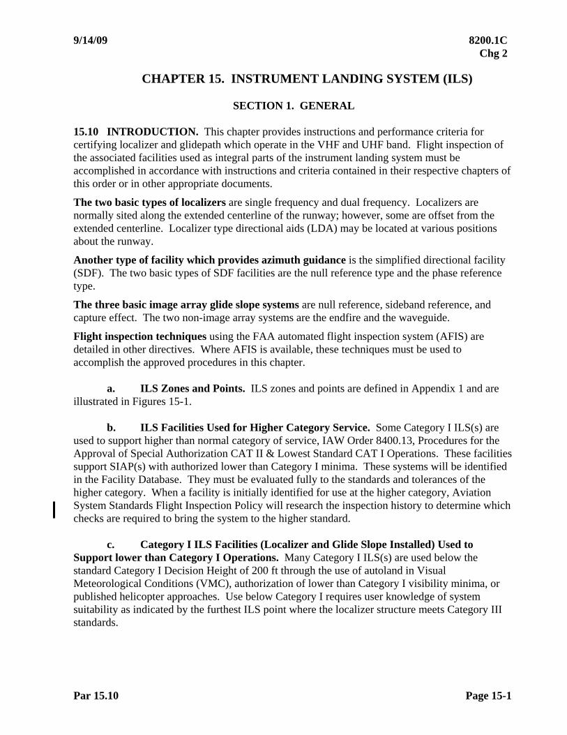
9/14/09 8200.1C Chg 2
Par 15.10 Page 15-1
CHAPTER 15. INSTRUMENT LANDING SYSTEM (ILS)
SECTION 1. GENERAL
15.10 INTRODUCTION. This chapter provides instructions and performance criteria for certifying localizer and glidepath which operate in the VHF and UHF band. Flight inspection of the associated facilities used as integral parts of the instrument landing system must be accomplished in accordance with instructions and criteria contained in their respective chapters of this order or in other appropriate documents.
The two basic types of localizers are single frequency and dual frequency. Localizers are normally sited along the extended centerline of the runway; however, some are offset from the extended centerline. Localizer type directional aids (LDA) may be located at various positions about the runway.
Another type of facility which provides azimuth guidance is the simplified directional facility (SDF). The two basic types of SDF facilities are the null reference type and the phase reference type.
The three basic image array glide slope systems are null reference, sideband reference, and capture effect. The two non-image array systems are the endfire and the waveguide.
Flight inspection techniques using the FAA automated flight inspection system (AFIS) are detailed in other directives. Where AFIS is available, these techniques must be used to accomplish the approved procedures in this chapter.
a. ILS Zones and Points. ILS zones and points are defined in Appendix 1 and are
illustrated in Figures 15-1.
b. ILS Facilities Used for Higher Category Service. Some Category I ILS(s) are used to support higher than normal category of service, IAW Order 8400.13, Procedures for the Approval of Special Authorization CAT II & Lowest Standard CAT I Operations. These facilities support SIAP(s) with authorized lower than Category I minima. These systems will be identified in the Facility Database. They must be evaluated fully to the standards and tolerances of the higher category. When a facility is initially identified for use at the higher category, Aviation System Standards Flight Inspection Policy will research the inspection history to determine which checks are required to bring the system to the higher standard.
c. Category I ILS Facilities (Localizer and Glide Slope Installed) Used to Support lower than Category I Operations. Many Category I ILS(s) are used below the standard Category I Decision Height of 200 ft through the use of autoland in Visual Meteorological Conditions (VMC), authorization of lower than Category I visibility minima, or published helicopter approaches. Use below Category I requires user knowledge of system suitability as indicated by the furthest ILS point where the localizer structure meets Category III standards.

8200.1C 10/01/05
Page 15-2 Par 15.10c
(1) Qualifying Localizers must be evaluated for structure through Zone 5, and glide slope clearance below path must be evaluated to runway threshold. These limited checks are accomplished to evaluate the ILS's ability to provide service in the areas of expanded usage.
(2) The ILS is not evaluated to other Category II/ III tolerances since there will
be no published Category II/ III procedures.
(3) Based on the results of the localizer structure checks, classification codes from FAA Order 6750.24, ILS and Ancillary Electronic Component and Performance Requirements, must be updated and published in the Airport/ Facility Directory. For example, when Category I Localizer structure is satisfactory through Zone 5, the Airport / Facility Directory for that facility will be upgraded to I/ E.
(4) If the Glide Slope clearance below path checks are not satisfactory to runway threshold, Localizer Zones 4 and 5 structure must still be evaluated for potential takeoff guidance through Zone 5 using the Rollout procedure.
d. 75 MHz Markers. The marker beacon is a VHF radio transmitter which
propagates an elliptically-shaped (fan) vertical radiation pattern on an assigned frequency of 75 MHz. The radiation pattern is composed of a major and a minor axis. The major axis is defined as the longest diameter of the elipse, while the minor axis is the shortest diameter. See Figures 15-2 and 15-3.
Functionally, maker beacons provide an aural and visual indication of station passage in association with facilities providing course guidance. Identification is provided by both a modulation frequency and a keying code.
Although marker beacons are basically of the same type and function, their nomenclature is generally divided into two categories: ILS markers and fan markers. The operational requirements and category are dependent upon instrument flight procedural application.
(1) ILS Markers Description. These markers are located on the approximate instrument runway centerline-extended in accordance with installation criteria specified in other documents. They are installed to indicate the position of an aircraft along the instrument approach course.
Outer Marker (OM)
Modulation Frequency. 400 Hz, Visual Signal—Illuminates the blue lamp.
Keying Code. Continuous dashes as a rate of two per second.
Middle Marker (MM)
Modulation Frequency. 1300 Hz, Visual Signal—Illuminates the amber lamp.
Keying Code. Alternating dots and dashes at a rate of 95 combinations per minute.

10/01/05 8200.1C
Par 15.10d Page 15-3
Inner Marker (IM)
Modulation Frequency. 3000 Hz, Visual Signal—Illuminates the white lamp.
Keying Code. Continuous dots at a rate of six dots per second.
(2) Fan Markers (FM) Description. These markers are generally associated with nonprecision approach procedures. However, they may be associated with an ILS to serve as a localizer stepdown fix or MAP for circling approaches to secondary airports.
Modulation Frequency. 3,000 Hz, Visual Signal—Illuminates the white lamp.
Keying Code:
(a) Back Course Marker. Two dot pair at a rate of 95 pair per minute; older equipment 72 pair a minute.
(b) Other Installations. Morse code letter R ( ). Where more than one approach marker is located in the same area, different identification keying is necessary to avoid confusion. The Morse code letters K ( ), P ( ), X ( ), and Z ( ) will be used in the priority listed. 15.11 PREFLIGHT REQUIREMENTS
a. ILS Facilities Maintenance Personnel. Prepare for flight inspection in accordance with Chapter 4, Section 3.
b. ILS Flight Check Personnel. Prepare for flight inspection in accordance with Chapter 4, Section 3.
c. ILS Special Equipment Requirements. AFIS is the standard system for ILS flight inspection and must be used for all commissioning checks except where RTT is required to support military contingencies. RTT may be used for all other checks; however, it should not be used solely to bypass the need for facility data of sufficient accuracy to support AFIS. AFIS or RTT must be used for all categorization or After-Accident checks. Except as limited by this paragraph, a standard theodolite may be used as indicated below:
(1) CAT I/ II/ III Localizer periodic or special checks
(2) CAT I Glide Slope periodic or special checks
(3) CAT II/ III Glide Slope checks not requiring determination of actual path angle or path structure.
d. ILS Glidepath Origination Point. The glidepath origination point is required for AFIS-equipped aircraft. For image array glide slopes, engineering personnel must supply the latitude/ longitude of the antenna mast and the mean sea level elevation of the glidepath origination point. For non-image arrays, engineering personnel must supply the latitude, longitude, and mean sea level altitude of the glidepath origination point.
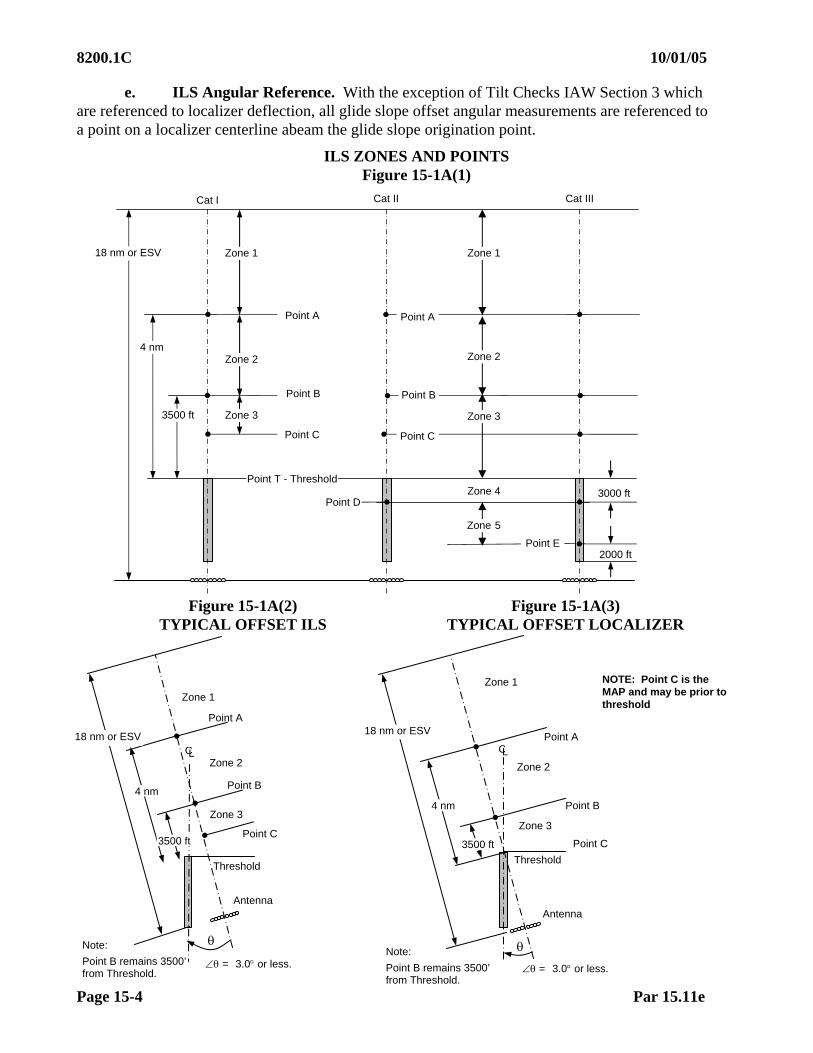
8200.1C 10/01/05
Page 15-4 Par 15.11e
e. ILS Angular Reference. With the exception of Tilt Checks IAW Section 3 which are referenced to localizer deflection, all glide slope offset angular measurements are referenced to a point on a localizer centerline abeam the glide slope origination point.
ILS ZONES AND POINTS Figure 15-1A(1)
Figure 15-1A(2) Figure 15-1A(3) TYPICAL OFFSET ILS TYPICAL OFFSET LOCALIZER
Point T - Threshold
Point DZone 4 3000 ft
2000 ft
Cat II
Zone 3
18 nm or ESV
4 nm
3500 ft
Point B
Point C
Point E
Point A
Cat I Cat III
Zone 2
Zone 1 Zone 1
Zone 2
Zone 3
Zone 5
Point B
Point C
Point A
Threshold
Point C
Point B
Zone 1
Zone 2
Point A
18 nm or ESV
4 nm
Zone 3
Antenna
CL
Note:
Point B remains 3500’ from Threshold.
3500 ft
= 3.0 or less.
Threshold
Point C
Point B
Zone 1
Zone 2
Point A 18 nm or ESV
4 nm
Zone 3
Antenna
CL
= 3.0 or less.
3500 ft
Note:
Point B remains 3500’ from Threshold.
NOTE: Point C is the MAP and may be prior to threshold
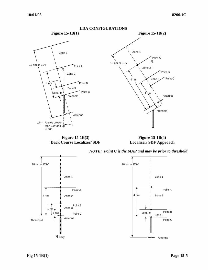
10/01/05 8200.1C
Fig 15-1B(1) Page 15-5
LDA CONFIGURATIONS
Figure 15-1B(1) Figure 15-1B(2)
Figure 15-1B(3) Figure 15-1B(4)
Back Course Localizer/ SDF Localizer/ SDF Approach
NOTE: Point C is the MAP and may be prior to threshold
Antenna
4 nm
Point C
Point B
Zone 1
Zone 2
Point A
Zone 3 3500 ft
18 nm or ESV
Antenna A t
4 nm
Point C
Point B
Zone 1
Zone 2
Point A
Zone 3
CL Rwy
3000 ft
18 nm or ESV
Threshold
1 nm
Threshold Point C
Point B
Zone 1
Zone 2
Point A 18 nm or ESV
4 nm
Zone 3 3500 ft
Antenna
CL
= Angles greater than 3.0 and up to 30.
Threshold
Point C
Point B
Zone 1
Antenna
Zone 2
Point A
18 nm or ESV
4 nm Zone 3
1 nm
CL

8200.1C 10/01/05
Page 15-6 Par 15.11f
f. ILS Theodolite Procedures. The RTT or theodolite will be positioned in accordance with the following criteria:
(1) Glide Slope Image Array Systems
(a) First Method
1 Through engineering survey data or by use of the theodolite itself, determine the difference in elevation, to the nearest inch, between the ground plane at the base of the antenna mast and the center of the runway opposite the mast. This can be accomplished by sighting with the theodolite to a surveyor's marker pole placed at the center of the runway opposite the mast or vice versa. If the crown of the runway is higher than the ground level at the antenna, the difference is treated as a minus value; if lower, the difference is a plus value. If the elevation difference determined above (minus value only) provides a comfortable eyepiece height, the theodolite may be positioned at that height at the base of the antenna mast and steps 2 through 5 disregarded.
NOTE: Where the elevation of the base of the antenna mast is more than 62 inches lower than the center of the runway opposite the antenna, alternate procedures to theodolite positioning should be considered. One such alternate is to apply steps 1 through 5 using an image position for the antenna base on the side of the runway opposite the facility.
2 Place the theodolite at the base of the glide slope antenna
mast with the eyepiece 62 inches above the ground.
3 Sight along a line between the antenna mast and the center of the runway threshold with the eyepiece set at the commissioned or desired vertical angle.
4 Using a marker pole, determine the position on the ground along the line in Step 3 which is exactly 124 inches, plus or minus the elevation difference obtained from Step 1. For example, if the runway is higher, subtract the elevation difference from 124 inches, if lower, add the elevation difference to 124 inches.
5 Establish the eyepiece height of the theodolite at 62 inches with the commissioned angle (or desired vertical angle) of the glidepath set in the theodolite.
(b) Second Method. This method applies to locations where the
transverse slope between the glide slope antenna base and the runway edge is irregular, e.g., pedestal runway. The determination of the irregular transverse slope and use of this procedure must be made by engineering/ installation personnel.
1 Place the theodolite at the base of the glide slope antenna
mast with the eyepiece 62 inches above the ground. 2 Sight along a line between the glide slope antenna mast and
the center of the runway threshold with the eyepiece set at the commissioned angle (or desired vertical angle).
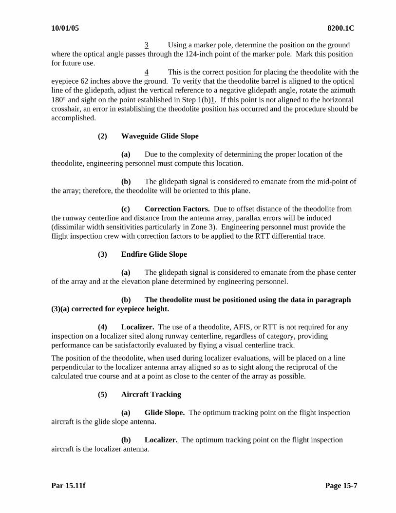
10/01/05 8200.1C
Par 15.11f Page 15-7
3 Using a marker pole, determine the position on the ground where the optical angle passes through the 124-inch point of the marker pole. Mark this position for future use.
4 This is the correct position for placing the theodolite with the eyepiece 62 inches above the ground. To verify that the theodolite barrel is aligned to the optical line of the glidepath, adjust the vertical reference to a negative glidepath angle, rotate the azimuth 180 and sight on the point established in Step 1(b)1. If this point is not aligned to the horizontal crosshair, an error in establishing the theodolite position has occurred and the procedure should be accomplished.
(2) Waveguide Glide Slope
(a) Due to the complexity of determining the proper location of the
theodolite, engineering personnel must compute this location.
(b) The glidepath signal is considered to emanate from the mid-point of the array; therefore, the theodolite will be oriented to this plane.
(c) Correction Factors. Due to offset distance of the theodolite from
the runway centerline and distance from the antenna array, parallax errors will be induced (dissimilar width sensitivities particularly in Zone 3). Engineering personnel must provide the flight inspection crew with correction factors to be applied to the RTT differential trace.
(3) Endfire Glide Slope
(a) The glidepath signal is considered to emanate from the phase center
of the array and at the elevation plane determined by engineering personnel. (b) The theodolite must be positioned using the data in paragraph
(3)(a) corrected for eyepiece height.
(4) Localizer. The use of a theodolite, AFIS, or RTT is not required for any inspection on a localizer sited along runway centerline, regardless of category, providing performance can be satisfactorily evaluated by flying a visual centerline track.
The position of the theodolite, when used during localizer evaluations, will be placed on a line perpendicular to the localizer antenna array aligned so as to sight along the reciprocal of the calculated true course and at a point as close to the center of the array as possible.
(5) Aircraft Tracking
(a) Glide Slope. The optimum tracking point on the flight inspection
aircraft is the glide slope antenna. (b) Localizer. The optimum tracking point on the flight inspection
aircraft is the localizer antenna.
8200.1C 10/01/05
Page 15-8 Par 15.11g
g. 75 MHz Marker Facilities Maintenance Personnel. The following information must be furnished to flight inspection prior to the commissioning check:
(1) The proposed operational configuration of any adjacent marker beacon
facilities which could produce interference (e.g., simultaneous operation proposed or interlock device installed).
(2) Any facility alterations performed because of unique siting requirements
(e.g., 8 KHz frequency separation between markers serving parallel approaches).
h. 75 MHz Marker Flight Check Personnel. The calibration card must be used to obtain the milliampere equivalent of 1,700 microvolts (V) required for each modulation frequency (400 Hz, 1,300 Hz, 3,000 Hz) (e.g., 1.8 milliampere (mA) may represent the 1,700 V level instead of 2.0 mA). Determine the number of light lines which represent the 1,700 V signal, and use this reference as the minimum acceptable signal level when evaluating marker beacon coverage.
15.12 FLIGHT INSPECTION PROCEDURES
a. Types of Inspections and General Procedures
(1) ILS Site Evaluations. Site evaluations, if performed, are made prior to installation of permanent equipment. The need for a site evaluation, and additional requirements, must be determined by engineering personnel on the basis of individual site conditions.
(2) Periodic Checks. A periodic check without monitors must consist of an
inspection of the localizer and glide slope transmitter that is on the air, plus the operating transmitter of the supporting NAVAID(s). If out-of-tolerance conditions are found, inspect the standby equipment, if available.
(3) Periodic with Monitors. Normally consists of a periodic performed on
both primary and standby equipment, a monitor check on the operating transmitter, and a check on the operating transmitter of supporting NAVAID(s). Facilities that have dual parallel monitors require a monitor evaluation on one transmitter only. Matching transmitter power and phasing parameters is a maintenance action verifiable without airborne measurements. Facilities gathering reference data may request a special flight inspection to include a monitor check on both transmitters. Dual transmitter facilities with separate and dedicated monitors for each transmitter require monitor evaluation on each transmitter. On the same transmitter that monitors are checked, perform a normal localizer course width and/ or glide slope path width prior to checking the monitor conditions.
(4) Frequency Change. Following a localizer (SDF, LDA) or ILS frequency
change, conduct a special inspection that fulfills the following requirements: Periodic with monitors (Pm), RF power monitor reference, and spectrum analysis.
(5) Other Component Changes. See Chapter 4, Section 1.

9/14/09 8200.1C Chg 2
Par 15.12a Page 15-9
(6) Restrictions Based on Commissioning-Only Checks. When a facility restriction is based on a configuration normally checked only on commissioning inspections (e.g., localizer clearances in narrow or coverage with reduced power), document the condition and configuration on the Facility Data Sheet. Conditions found in these configurations do not require revalidation on periodic inspections.
(7) Restriction Removal. Restricted facilities must be evaluated on each inspection with the goal of removing restrictions that are no longer valid. Do not check configurations beyond the scope of the scheduled inspection, unless restriction removal can be expected. If the results of the current and last periodic interval inspections indicate a potential for restriction removal, notify the Aviation System Standards Flight Inspection Policy. They must review at least the last five years of inspection history. They must analyze the history and current results for maintenance actions, trends, seasonal differences, etc., to determine if restriction removal is appropriate. If an additional inspection is required, they must specify and schedule the required checks to be done with the next appropriate inspection. For those restrictions based on commissioning-only configurations, do not remove the restrictions without a check of those configurations.
(8) Back Course Use. A localizer back course used for missed approach guidance must meet the same checklist requirements and tolerances as one used for an approach.
(9) ILS Critical Area Checks. These checks are usually requested to determine the effects of permitting aircraft, vehicles, or other mobile objects to transition through ILS critical areas. The results of these flight inspections are valid only for the specific conditions existing at the time of the check and are not suitable for determination of facility performance status or reliability.
(10) Maintenance Request Checks. Items identified as “Maintenance Request” in the individual checklists are so labeled to support current FAA maintenance practices with current FAA equipment. They usually identify checks that can be performed using ground test equipment, as well as aircraft. While FAA maintenance may be able to do these checks, other maintenance activities may require flight inspection for these parameters. Flight inspection and maintenance personnel must discuss these items to ensure the adequacy of the flight check.
b. Standby Equipment – Localizer/ Glide Slope. Where dual equipment is
installed, complete all checklist items for both sets of equipment, except as noted in the text of this chapter and the checklists. For FAA, U.S. Non-Federal civil, U.S. Army, and U.S. Navy/ Marine Corps facilities, standby transmitters should match the reference transmitter within the prescribed equality in normal maintenance limits during the same flight inspection. Applies to all type inspections when both primary and standby transmitters are evaluated in normal. If Maintenance is unable to adjust the transmitter within equality limits and the transmitter meets Paragraph 15.60a and b flight inspection tolerances, the transmitter may remain in service unless Maintenance elects to remove it from service.

8200.1C 02/01/07 CHG 1
Page 15-10 Par 15.12d
Dual Transmitter Equality in Normal Maintenance Limits
Localizer (Normal Only) Alignment 3 A Width 0.10 Clearance 15 A Glide Slope (Normal Only) Angle 0.03 Width 0.03 Structure Below Path 0.20
c. Standby Power – Localizer/ Glide Slope. Refer to Chapter 4, Section 3. If
required, make the following checks while operating on standby power.
(1) Localizer. Course width, alignment, symmetry, modulation, and identification.
(2) Glide Slope. Modulation, width, angle, symmetry, and structure below path.
d. Expanded Service Volume (ESV). Where an operational requirement exists to use either or both the glide slope and localizer to altitudes and/or distances beyond the standard service volume, the facility (ies) must be inspected to the expanded altitudes and/or distances (in accordance with Paragraph 22.11b) to determine that facility performance for the required parameters meets tolerances.
(1) Localizer. The localizer Standard Service Volume (SSV) is depicted in Figure 15-12. Use beyond these limits requires an ESV approved by spectrum management and validated by flight inspection.
(2) Glide Slope. The glide slope SSV is depicted in Figure 15-13.
e. Supporting NAVAID(s). These may consist of marker beacons, a compass locator, DME, and/or lighting systems. Additionally, some locations may require other types of NAVAID(s) to support the approach procedures. Verify RHO-THETA crossing radials associated with an ILS approach IAW Chapter 11.
f. Instrument Flight Procedures. See Chapter 6.
g. General Checklist. During a specific inspection, check the following items:
A E C PM P 75 MHz Marker Beacons X - X X X Compass Locator X - X X X DME X - X X X Lighting Systems X - X X X Standard Instrument Approach Procedure (see Chapter 4, Section 2 and Chapter 6)
X (1) X (1) (1)
NOTE: (1) As required by ground technical or flight inspection personnel.
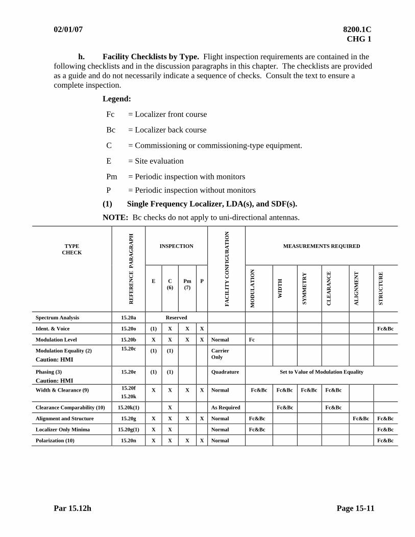
02/01/07 8200.1C CHG 1
Par 15.12h Page 15-11
h. Facility Checklists by Type. Flight inspection requirements are contained in the following checklists and in the discussion paragraphs in this chapter. The checklists are provided as a guide and do not necessarily indicate a sequence of checks. Consult the text to ensure a complete inspection.
Legend:
Fc = Localizer front course
Bc = Localizer back course
C = Commissioning or commissioning-type equipment.
E = Site evaluation
Pm = Periodic inspection with monitors
P = Periodic inspection without monitors
(1) Single Frequency Localizer, LDA(s), and SDF(s).
NOTE: Bc checks do not apply to uni-directional antennas.
INSPECTION MEASUREMENTS REQUIRED TYPE CHECK
RE
FE
RE
NC
E P
AR
AG
RA
PH
E C (6)
Pm (7)
P
FA
CIL
ITY
CO
NF
IGU
RA
TIO
N
MO
DU
LA
TIO
N
WID
TH
SY
MM
ET
RY
CL
EA
RA
NC
E
AL
IGN
ME
NT
ST
RU
CT
UR
E
Spectrum Analysis 15.20a Reserved
Ident. & Voice 15.20o (1) X X X Fc&Bc
Modulation Level 15.20b X X X X Normal Fc
Modulation Equality (2)
Caution: HMI
15.20c (1) (1) Carrier Only
Phasing (3)
Caution: HMI
15.20e (1) (1) Quadrature Set to Value of Modulation Equality
Width & Clearance (9) 15.20f
15.20k X X X X Normal Fc&Bc Fc&Bc Fc&Bc Fc&Bc
Clearance Comparability (10) 15.20k(1) X As Required Fc&Bc Fc&Bc
Alignment and Structure 15.20g X X X X Normal Fc&Bc Fc&Bc Fc&Bc
Localizer Only Minima 15.20g(1) X X Normal Fc&Bc Fc&Bc
Polarization (10) 15.20n X X X X Normal Fc&Bc
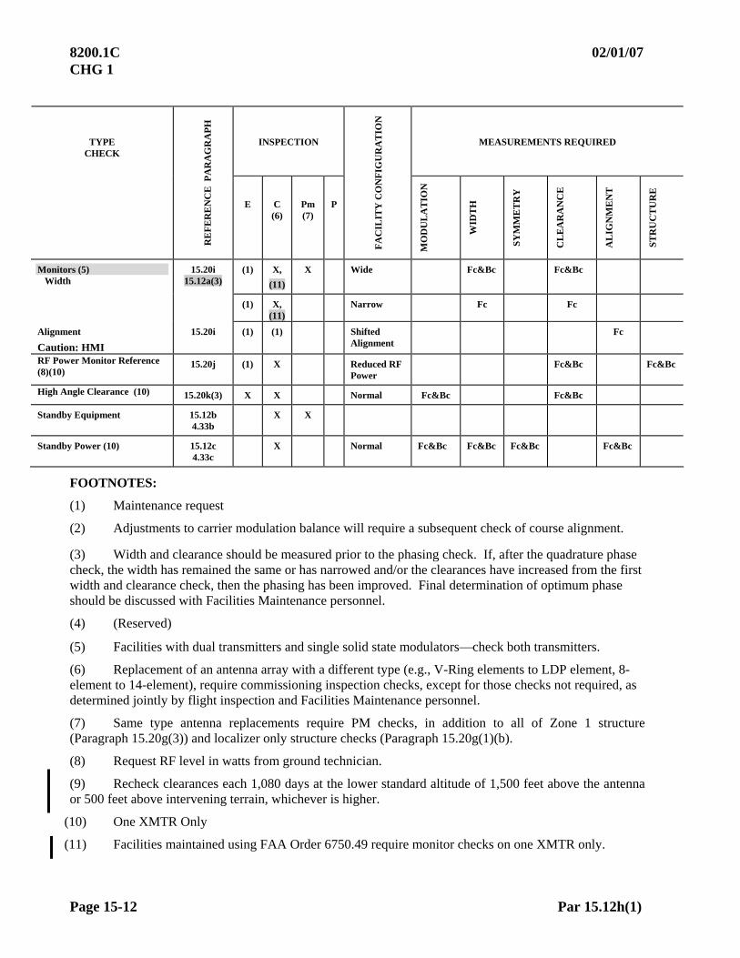
8200.1C 02/01/07 CHG 1
Page 15-12 Par 15.12h(1)
INSPECTION MEASUREMENTS REQUIRED TYPE CHECK
RE
FE
RE
NC
E P
AR
AG
RA
PH
E C
(6) Pm (7)
P
FA
CIL
ITY
CO
NF
IGU
RA
TIO
N
MO
DU
LA
TIO
N
WID
TH
SY
MM
ET
RY
CL
EA
RA
NC
E
AL
IGN
ME
NT
ST
RU
CT
UR
E
Monitors (5) Width
15.20i 15.12a(3)
(1) X,
(11)
X Wide Fc&Bc Fc&Bc
(1) X, (11)
Narrow Fc Fc
Alignment
Caution: HMI
15.20i (1) (1) Shifted Alignment
Fc
RF Power Monitor Reference (8)(10)
15.20j (1) X Reduced RF Power
Fc&Bc Fc&Bc
High Angle Clearance (10) 15.20k(3) X X Normal Fc&Bc Fc&Bc
Standby Equipment 15.12b 4.33b
X X
Standby Power (10) 15.12c 4.33c
X Normal Fc&Bc Fc&Bc Fc&Bc Fc&Bc
FOOTNOTES:
(1) Maintenance request
(2) Adjustments to carrier modulation balance will require a subsequent check of course alignment.
(3) Width and clearance should be measured prior to the phasing check. If, after the quadrature phase check, the width has remained the same or has narrowed and/or the clearances have increased from the first width and clearance check, then the phasing has been improved. Final determination of optimum phase should be discussed with Facilities Maintenance personnel.
(4) (Reserved)
(5) Facilities with dual transmitters and single solid state modulatorscheck both transmitters.
(6) Replacement of an antenna array with a different type (e.g., V-Ring elements to LDP element, 8-element to 14-element), require commissioning inspection checks, except for those checks not required, as determined jointly by flight inspection and Facilities Maintenance personnel.
(7) Same type antenna replacements require PM checks, in addition to all of Zone 1 structure (Paragraph 15.20g(3)) and localizer only structure checks (Paragraph 15.20g(1)(b).
(8) Request RF level in watts from ground technician.
(9) Recheck clearances each 1,080 days at the lower standard altitude of 1,500 feet above the antenna or 500 feet above intervening terrain, whichever is higher.
(10) One XMTR Only
(11) Facilities maintained using FAA Order 6750.49 require monitor checks on one XMTR only.
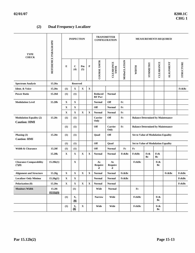
02/01/07 8200.1C CHG 1
Par 15.12h(2) Page 15-13
(2) Dual Frequency Localizer
TYPE CHECK
INSPECTION TRANSMITTER
CONFIGURATION MEASUREMENTS REQUIRED
RE
FE
RE
MC
E P
AR
AG
RA
PH
E C (4)
Pm(5)
P
CO
UR
SE
XM
TR
CL
EA
RA
NC
E
XM
TR
MO
Du
UL
AT
ION
WID
TH
SY
MM
ET
RY
CL
EA
RA
NC
E
AL
IGN
ME
NT
ST
RU
CT
UR
E
Spectrum Analysis 15.20a Reserved
Ident. & Voice 15.20o (1) X X X Fc&Bc
Power Ratio 15.20d (1) (1) Reduced RF Pwr
Normal
Modulation Level 15.20b X X Normal Off Fc
X X Off Normal Fc
X X X X Normal Normal Fc
Modulation Equality (2)
Caution: HMI
15.20c (1) (1) Carrier Only
Off Fc Balance Determined by Maintenance
(1) (1) Off Carrier Only
Fc Balance Determined by Maintenance
Phasing (3)
Caution: HMI
15.20e (1) (1) Quad Off Set to Value of Modulation Equality
(1) (1) Off Quad Set to Value of Modulation Equality
Width & Clearance 15.20f (1) (1) Off Normal Fc Fc
15.20k X X X X Normal Normal Fc&Bc Fc&Bc Fc&Bc
Fc&Bc
Clearance Comparability (7)(8)
15.20k(1) X As Require
d
As Require
d
Fc&Bc Fc&Bc
Alignment and Structure 15.20g X X X X Normal Normal Fc&Bc Fc&Bc Fc&Bc
Localizer Only Minima 15.20g(1) X X Normal Normal Fc&Bc Fc&Bc
Polarization (8) 15.20n X X X X Normal Normal Fc&Bc
Monitors Width 15.20i
15.12a(3) (1) Wide Normal Fc
(1) X,
(9)
Narrow Wide Fc&Bc Fc&Bc
(1) X, (9)
X Wide Wide Fc&Bc Fc&Bc

8200.1C 02/01/07 CHG 1
Page 15-14 Par 15.12h(2)
(2) Dual Frequency Localizer, continued
INSPECTION TRANSMITTER
CONFIGURATION MEASUREMENTS REQUIRED
TYPE CHECK
RE
FE
RE
MC
E
PA
RA
GR
AP
H
E C (4)
Pm (5)
P
CO
UR
SE
XM
TR
CL
EA
RA
NC
E
XM
TR
MO
DU
LA
TIO
N
WID
TH
SY
MM
ET
RY
CL
EA
RA
NC
E
AL
IGN
ME
NT
ST
RU
CT
UR
E
Dephase 15.20i (1) ADV Phase
Normal Fc
(1) RET Phase
Normal Fc
(1) Normal ADV Phase Fc Fc
(1) Normal RET Phase Fc Fc
Alignment
Caution: HMI
15.20i (1) Shifted Alignme
nt
Normal Fc
RF Power Monitor Reference (6)(8)
15.20j (1) X Reduced RF
Power
Reduced RF Power
Fc&Bc Fc&Bc
High Angle Clearance (8)
15.20k(3) X X Normal Normal Fc&Bc Fc&Bc
Standby Equipment 15.12b 4.33b
X X
Standby Power (8) 15.12c 4.33c
X Normal Normal Fc&Bc Fc&Bc Fc&Bc
Fc&Bc
FOOTNOTES:
(1) Maintenance request
(2) Adjustments to carrier modulation balance will require a subsequent check of course alignment.
(3) Width and clearance should be measured prior to the phasing check. If, after the quadrature phase check, the width has remained the same or has narrowed and/or the clearances have increased from the first width and clearance check, then the phasing has been improved. Final determination of optimum phase should be discussed with Facilities Maintenance personnel.
(4) Replacement of an antenna array with a different type (e.g., V-Ring elements to LDP element, 8-element to 14-element) require commissioning inspection checks, except for those checks not required, as determined jointly by flight inspection and Facilities Maintenance personnel.
(5) Same type antenna replacements require PM checks, in addition to all of Zone 1 structure (Paragraph 15.20g(3)) and localizer only structure checks. (Paragraph 15.20g(1)(b)).
(6) Request RF level in watts from ground technician.
(7) Recheck clearances each 1,080 days at the lower standard altitude of 1,500 feet above the antenna or 500 feet above intervening terrain, whichever is higher.
(8) One XMTR Only
(9) Facilities maintained using FAA Order 6750.49 require monitor checks on one XMTR only.

10/01/05 8200.1C
Par 15.12h(3) Page 15-15
(3) Null Reference Glide Slope
CODE: W/A/S = Width, Angle, Symmetry
INSPECTION MEASUREMENTS REQUIRED
TYPE CHECK
RE
FE
RE
NC
E
PA
RA
GR
AP
H
E C Pm P
FACILITY CONFIGURATION
MO
DU
LA
TIO
N
WID
TH
AN
GL
E
SY
MM
ET
RY
ST
RU
C B
EL
OW
P
AT
H
CL
EA
RA
NC
E
ST
RU
CT
UR
E
Spectrum Analysis 15.30a Reserved
Engineering Support
Tests (5)
Caution: HMI
15.30e (1) (1) As Required
Modulation Level 15.30b X X X X Normal X
Modulation Equality
Caution: HMI
15.30c (1) (1) Carrier Only X
Phasing
Caution: HMI
15.30d (1) (1) Quadrature SET TO VALUE FOUND IN MODULATION EQUALITY
Spurious Radiation 15.30e(3) (1) (1) Dummy Load Radiating Signal
X
W/A/S 15.30f X X X X Normal X X X X, (2)
Structure 15.30j X X X X Normal X X X
Clearance
(CBP One XMTR Only)
15.30g X X Normal X
Tilt (5)
15.30i X X Normal X X X
Mean Width (5)
15.30h (1) X Normal X X

8200.1C 02/01/07 CHG 1
Page 15-16 Par 15.12h(3)
(3) Null Reference Glide Slope (continued)
INSPECTION MEASUREMENTS REQUIRED
TYPE CHECK
RE
FE
RE
NC
E
PA
RA
GR
AP
H
E C Pm P
FACILITY CONFIGURATION
MO
DU
LA
TIO
N
WID
TH
AN
GL
E
SY
MM
ET
RY
ST
RU
C B
EL
OW
P
AT
H
CL
EA
RA
NC
E
ST
RU
CT
UR
E
Monitors Width 15.30m 15.12a(3)
(1) X, (6)
X ADV Phase X X X, (2) (3)
(1) X, (6)
X RET Phase X X X, (2) (3)
(1) X, (6)
X Wide X X X, (2) (3)
X, (6)
Narrow X X X, (2)
RF Power Monitor Reference
(4) (5)
15.30n (1) X Reduced RF Power
Standby Equipment 15.12b
4.33b
X X
Standby Power 15.12c
4.33c
X Normal X X X X X, (2)
FOOTNOTES:
(1) Maintenance request
(2) If structure below path tolerances cannot be met, clearance procedures and tolerances will be applied.
(3) Clearance Below Path (CBP) required on commissioning type inspections, one XMTR only.
(4) Request RF level in watts from ground technician.
(5) One XMTR Only
(6) Facilities maintained using FAA Order 6750.49 require monitor checks on one XMTR only.
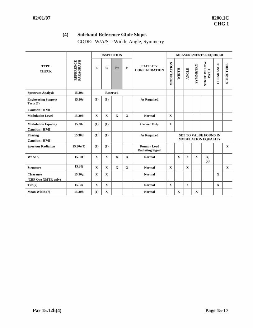
02/01/07 8200.1C CHG 1
Par 15.12h(4) Page 15-17
(4) Sideband Reference Glide Slope.
CODE: W/A/S = Width, Angle, Symmetry
INSPECTION MEASUREMENTS REQUIRED
TYPE
CHECK R
EF
ER
EN
CE
P
AR
AG
RA
PH
E C Pm P FACILITY CONFIGURATION
MO
DU
LA
TIO
N
WID
TH
AN
GL
E
SY
MM
ET
RY
ST
RU
C B
EL
OW
P
AT
H
CL
EA
RA
NC
E
ST
RU
CT
UR
E
Spectrum Analysis 15.30a Reserved
Engineering Support Tests (7)
Caution: HMI
15.30e (1) (1) As Required
Modulation Level 15.30b X X X X Normal X
Modulation Equality
Caution: HMI
15.30c (1) (1) Carrier Only X
Phasing
Caution: HMI
15.30d (1) (1) As Required SET TO VALUE FOUND IN MODULATION EQUALITY
Spurious Radiation 15.30e(3) (1) (1) Dummy Load Radiating Signal
X
W/ A/ S 15.30f X X X X Normal X X X X, (2)
Structure 15.30j X X X X Normal X X X
Clearance
(CBP One XMTR only)
15.30g X X Normal X
Tilt (7) 15.30i X X Normal X X X
Mean Width (7) 15.30h (1) X Normal X X

8200.1C 02/01/07 CHG 1
Page 15-18 Par 15.12h(4)
(4) Sideband Reference Glide Slope (Continued)
INSPECTION MEASUREMENTS REQUIRED
TYPE CHECK
REFERENCE PARAGRAPH.
E C Pm P FACILITY CONFIGURATION
MO
DU
LA
TIO
N
WID
TH
AN
GL
E
SY
MM
ET
RY
ST
RU
C B
EL
OW
P
AT
H
CL
EA
RA
NC
E
ST
RU
CT
UR
E
Monitors (5) Angle
15.30m 15.12a(3)
(1) (1) High Angle (4) X X, (4)
X, (2)
(1) X, (8)
X Low Angle (4) X X, (4)
X, (2)
(3)
Width 15.30m Upper Antenna:
X, (8)
X ADV Phase X X X, (2)
(3)
X, (8)
X RET Phase X X X, (2)
(3)
Main Sideband:
(1) ADV Phase X X X, (2)
(1) RET Phase X X X, (2)
(1) X, (8)
X Wide X X X, (2)
(3)
X, (8)
Narrow X X X, (2)
RF Power Monitor Reference (6) (7)
15.30n (1) X Reduced RF Power
Standby Equipment 15.12b 4.33b
X X
Standby Power 15.12c 4.33c
X Normal X X X X X, (2)
FOOTNOTES:
(1) Maintenance request
(2) If structure below path tolerances cannot be met, clearance procedures and tolerances will be applied.
(3) Clearance Below Path (CBP) required on commissioning type inspections, one XMTR only.
(4) Check on one transmitter only if equipment has a common power divider and parallel monitors.
(5) Perform a final actual angle check at the completion of any width or angle monitor inspection.
(6) Request RF level in watts from ground technician.
(7) One XMTR Only
(8) Facilities maintained using FAA Order 6750.49 require monitor checks on one XMTR only.

10/01/05 8200.1C
Par 15.12h(5) Page 15-19
(5) Capture Effect Glide Slope
CODE: W/A/S = Width, Angle, Symmetry
INSPECTION MEASUREMENTS REQUIRED
TYPE CHECK
RE
FE
RE
NC
E
PA
RA
GR
AP
H
E C Pm P
FA
CIL
ITY
C
ON
FIG
UR
AT
ION
MO
DU
LA
TIO
N
WID
TH
AN
GL
E
SY
MM
ET
RY
ST
RU
C T
UR
E
BE
LO
W P
AT
H
CL
EA
RA
NC
E
ST
RU
CT
UR
E
Spectrum Analysis 15.30a Reserved
Engineering Support Tests (7)
Caution: HMI
15.30e (1) (1) As Required
Modulation Level 15.30b X X X X Normal: X
Modulation Equality
Caution: HMI 15.30c (1) (1) Carrier Only X
Phasing Proc. 1 or 2
Caution: HMI 15.30d(3) (1) (1) As Required SET TO VALUE FOUND IN
MODULATION EQUALITY
Phase Verification (4) 15.30d(3) (1) X As Required X X X X X
Spurious Radiation 15.30e(3) (1) (1) Dummy Load Radiating
Signal
X
W/ A/ S 15.30f
X X X X Normal X X X X, (2)
Structure 15.30j
X X X X Normal X X X
Clearance (CBP One XMTR only)
15.30g X X Normal X

8200.1C 9/14/09 Chg 2
Page 15-20 Par 15.12h(5)
(5) Capture Effect Glide Slope (continued)
INSPECTION MEASUREMENTS REQUIRED
TYPE
CHECK R
EF
ER
EN
CE
P
AR
AG
RA
PH
E C Pm P FACILITY CONFIGURATION
MO
DU
LA
TIO
N
WID
TH
AN
GL
E
SY
MM
ET
RY
ST
RU
C T
UR
E
BE
LO
W P
AT
H
CL
EA
RA
NC
E
ST
RU
CT
UR
E
Tilt (7) 15.30i X X Normal X X X
Mean Width (7) 15.30h (1) X Normal X X
Monitors Width
15.30m 15.12a(3)
(1)
X, (8)
X
Middle Antenna ADV Phase
X
X
X, (2)
(3) (5)
(1) X, (8)
X RET Phase X X X, (2) (3) (5)
(1)
(1)
X, (8)
X, (8)
X
Narrow
Primary XMTR wide and clearance XMTR reduced modulation
X
X
X
X
X, (2)
X, (2)
(3)
(1) (1) Middle Antenna Attenuate
X X X, (2) (3)
(1) X, (8)
X Upper Antenna Attenuate
X X X, (2)
RF Power Monitor Reference (6) (7)
15.30n (1) X Reduced RF Power
Standby Equipment
15.12b 4.33b
X X
Standby Power 15.12c 4.33c
X Normal X X X X X, (2)
FOOTNOTES:
(1) Maintenance request
(2) If structure below path tolerances cannot be met, clearance procedures and tolerances will be applied.
(3) Clearance Below Path (CBP) required on commissioning type inspections, one XMTR only.
(4) Normally required on only one transmitter. Perform on second transmitter at maintenance request.
(5) CBP not required if the dephasing is equal to or less than the amount used for phase verification.
(6) Request RF level in watts from ground technician.
(7) One XMTR Only
(8) Facilities maintained using FAA Order 6750.49 require monitor checks on one XMTR only.
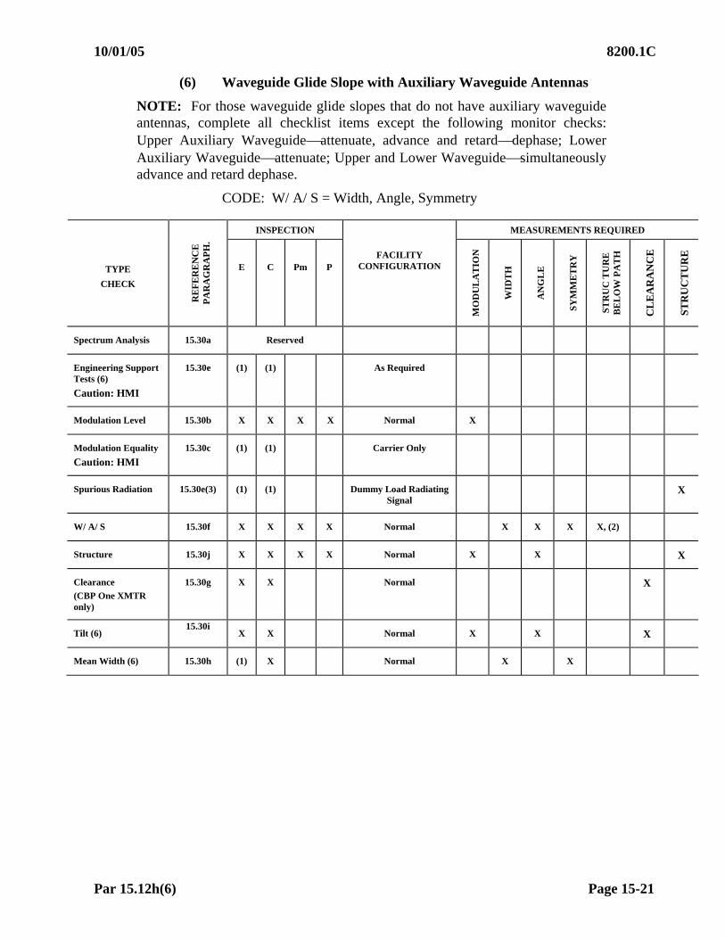
10/01/05 8200.1C
Par 15.12h(6) Page 15-21
(6) Waveguide Glide Slope with Auxiliary Waveguide Antennas
NOTE: For those waveguide glide slopes that do not have auxiliary waveguide antennas, complete all checklist items except the following monitor checks: Upper Auxiliary Waveguideattenuate, advance and retarddephase; Lower Auxiliary Waveguideattenuate; Upper and Lower Waveguidesimultaneously advance and retard dephase.
CODE: W/ A/ S = Width, Angle, Symmetry
INSPECTION MEASUREMENTS REQUIRED
TYPE
CHECK
RE
FE
RE
NC
E
PA
RA
GR
AP
H.
E C Pm P FACILITY
CONFIGURATION
MO
DU
LA
TIO
N
WID
TH
AN
GL
E
SY
MM
ET
RY
ST
RU
C T
UR
E
BE
LO
W P
AT
H
CL
EA
RA
NC
E
ST
RU
CT
UR
E
Spectrum Analysis 15.30a Reserved
Engineering Support Tests (6)
Caution: HMI
15.30e (1) (1) As Required
Modulation Level 15.30b X X X X Normal X
Modulation Equality
Caution: HMI 15.30c (1) (1) Carrier Only
Spurious Radiation 15.30e(3) (1) (1) Dummy Load Radiating Signal
X
W/ A/ S 15.30f X X X X Normal X X X X, (2)
Structure 15.30j X X X X Normal X X X
Clearance
(CBP One XMTR only)
15.30g X X Normal X
Tilt (6) 15.30i
X X Normal X X X
Mean Width (6) 15.30h (1) X Normal X X

8200.1C 02/01/07 CHG 1
Page 15-22 Par 15.12h(6)
(6) Waveguide Glide Slope with Auxiliary Waveguide Antennas (continued)
INSPECTION MEASUREMENTS REQUIRED
TYPE
CHECK
RE
FE
RE
NC
E
PA
RA
GR
AP
H
E C Pm P FACILITY CONFIGURATION
MO
DU
LA
TIO
N
WID
TH
AN
GL
E
SY
MM
ET
RY
ST
RU
C T
UR
E
BE
LO
W P
AT
H
CL
EA
RA
NC
E
ST
RU
CT
UR
E
Monitors Width
15.30m
(1)
X
X
X
Wide
Narrow
X
X
X
X
X, (2)
X, (2)
(3)
X
X
X
X
Main Sideband:
ADV Phase
RET Phase
X
X
X
X
X, (2)
X, (2)
(3)
(3)
(6)
X X X
Upper Auxiliary Waveguide:
Attenuate ADV Phase RET Phase
X X X
X, (4) X, (4) X, (4)
X X X
X X X
(6)
X
Lower Auxiliary Waveguide: Attenuate
X
X, (4)
X
X
(6)
X X
Upper & Lower Waveguide
Simultaneously:
ADV Phase RET Phase
X X
X X
X, (2) X, (2)
X X
(6)
X X
X X
Main Waveguide Feed Phaser:
ADV Phase (4) RET Phase (4)
X X
X X
X, (2) X, (2)
(3) (3)
Angle (6) X
Lower Main
Waveguide Feed: Attenuate
(High Angle)
X
X
X, (2)
(6) X Upper Main
Waveguide Feed: Attenuate
(Low Angle)
X
X
X, (2)
(3)
RF Power Monitor Reference (5) (6)
15.30n (1) X Reduced RF Power
Standby Equipment 15.12b 4.33b
X X
Standby Power 15.12c 4.33c
X Normal X X X X X, (2)
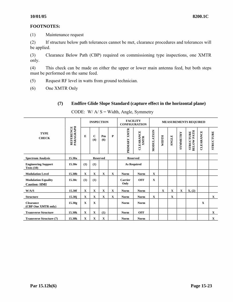
10/01/05 8200.1C
Par 15.12h(6) Page 15-23
FOOTNOTES:
(1) Maintenance request
(2) If structure below path tolerances cannot be met, clearance procedures and tolerances will be applied.
(3) Clearance Below Path (CBP) required on commissioning type inspections, one XMTR only.
(4) This check can be made on either the upper or lower main antenna feed, but both steps must be performed on the same feed.
(5) Request RF level in watts from ground technician.
(6) One XMTR Only
(7) Endfire Glide Slope Standard (capture effect in the horizontal plane)
CODE: W/ A/ S = Width, Angle, Symmetry
INSPECTION FACILITY CONFIGURATION
MEASUREMENTS REQUIRED
TYPE
CHECK
RE
FE
RE
NC
E
PA
RA
GR
AP
H
E C (4)
Pm (6)
P
PR
IMA
RY
XM
TR
CL
EA
RA
NC
E
XM
TR
MO
DU
LA
TIO
N
WID
TH
AN
GL
E
SY
MM
ET
RY
ST
RU
CT
UR
E
BE
LO
W P
AT
H
CL
EA
RA
NC
E
ST
RU
CT
UR
E
Spectrum Analysis 15.30a Reserved Reserved
Engineering Support Tests (10)
15.30e (1) (1) As Required
Modulation Level 15.30b X X X X Norm Norm X
Modulation Equality
Caution: HMI 15.30c (1) (1) Carrier
Only OFF X
W/A/S 15.30f X X X X Norm Norm X X X X, (2)
Structure 15.30j X X X X Norm Norm X X X
Clearance (CBP One XMTR only)
15.30g X X Norm Norm X
Transverse Structure 15.30k X X (1) Norm OFF X
Transverse Structure (7) 15.30k X X X Norm Norm X
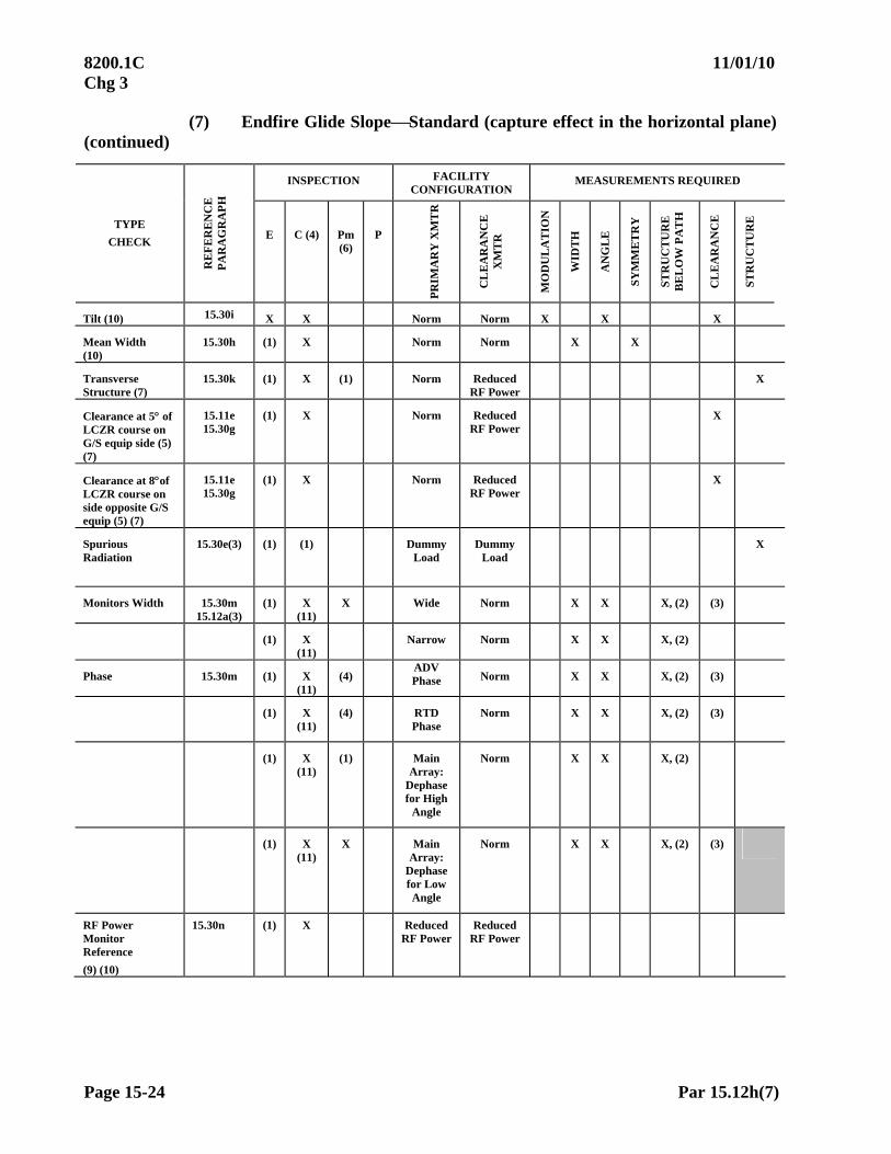
8200.1C 11/01/10 Chg 3
Page 15-24 Par 15.12h(7)
(7) Endfire Glide SlopeStandard (capture effect in the horizontal plane) (continued)
INSPECTION FACILITY CONFIGURATION
MEASUREMENTS REQUIRED
TYPE
CHECK
RE
FE
RE
NC
E
PA
RA
GR
AP
H
E C (4) Pm (6)
P
PR
IMA
RY
XM
TR
CL
EA
RA
NC
E
XM
TR
MO
DU
LA
TIO
N
WID
TH
AN
GL
E
SY
MM
ET
RY
ST
RU
CT
UR
E
BE
LO
W P
AT
H
CL
EA
RA
NC
E
ST
RU
CT
UR
E
Tilt (10) 15.30i X X Norm Norm X X X
Mean Width (10)
15.30h (1) X Norm Norm X X
Transverse Structure (7)
15.30k (1) X (1) Norm Reduced RF Power
X
Clearance at 5 of LCZR course on G/S equip side (5) (7)
15.11e 15.30g
(1) X Norm Reduced RF Power
X
Clearance at 8of LCZR course on side opposite G/S equip (5) (7)
15.11e 15.30g
(1) X Norm Reduced RF Power
X
Spurious Radiation
15.30e(3) (1) (1) Dummy Load
Dummy Load
X
Monitors Width 15.30m 15.12a(3)
(1) X (11)
X Wide Norm X X X, (2) (3)
(1) X (11)
Narrow Norm X X X, (2)
Phase 15.30m (1) X (11)
(4) ADV Phase Norm X X X, (2) (3)
(1) X (11)
(4) RTD Phase
Norm X X X, (2) (3)
(1) X (11)
(1) Main Array:
Dephase for High
Angle
Norm X X X, (2)
(1) X
(11) X Main
Array: Dephase for Low Angle
Norm X X X, (2) (3)
RF Power Monitor Reference
(9) (10)
15.30n (1) X Reduced RF Power
Reduced RF Power

02/01/07 8200.1C CHG 1
Par 15.20h(7) Page 15-25
(7) Endfire Glide SlopeStandard (capture effect in the horizontal plane) (continued)
INSPECTION FACILITY CONFIGURATION
MEASUREMENTS REQUIRED
TYPE
CHECK R
EF
ER
EN
CE
P
AR
AG
RA
PH
E C (4) Pm
(6) P
PR
IMA
RY
X
MT
R
CL
EA
RA
NC
E
XM
TR
MO
DU
LA
TIO
N
WID
TH
AN
GL
E
SY
MM
ET
RY
ST
RU
CT
UR
E
BE
LO
W P
AT
H
CL
EA
RA
NC
E
ST
RU
CT
UR
E
Transverse Structure
15.30k (1) (8) (11)
Norm
ADV front CLR ANT
Phase
X
(1)(8)
(11) Norm
RET front CLR ANT
Phase
X
Standby Equipment
15.12b 4.33b
X X
Standby Power
15.12c 4.33c
X
X X X X X, (2)
FOOTNOTES:
(1) Maintenance request
(2) If structure-below-path tolerances cannot be met, clearance procedures and techniques will be applied.
(3) Clearance Below Path (CBP) required on commissioning type inspections, one XMTR only.
(4) On facilities without a quadrature phase monitor (Path 2 Detector), conduct dephase check on the width monitor with main sideband dephasing of 15 or less. If a quadrature phase monitor is installed, a commissioning check is required, but no periodic dephase check is needed.
(5) Clearance above and below path required. (See Paragraph 15.11e.)
(6) Perform a final actual angle check at the completion of any width or angle monitor inspection.
(7) Perform also after antenna repair, replacement, modification, or any adjustment maintenance expects will change transverse structure and/or clearances.
(8) Not applicable to Single Clearance Antennas.
(9) Request RF level in watts from ground technician.
(10) One XMTR Only
(11) Facilities maintained using FAA Order 6750.49 require monitor checks on one XMTR only.

8200.1C 10/01/05
Page 15-26 Par 15.12h(8)
(8) 75 MHz Marker Beacon Checklist. Markers are installed as a constituent part of some other primary aid; therefore, they are inspected concurrently with the primary aid.
ILS AND FAN MARKERS
Inspections
Type Check Reference Paragraph Commissioning Periodic
Antenna and/or Transmission Lines
Replacement/ Adjustment
Spectrum Analysis 15.40a Reserved Reserved
Identification and Modulation Tone
15.40b
X
X
X
Coverage 15.40c Major Axis 15.40c(2) X - X Minor Axis 15.40c(1) X X X Proximity Check 15.40d X - X
Holding Fixes 15.40f X - X Standby Equipment
15.40g 4.33b
X
-
-
Standby Power
15.40h 4.33c
X
-
-
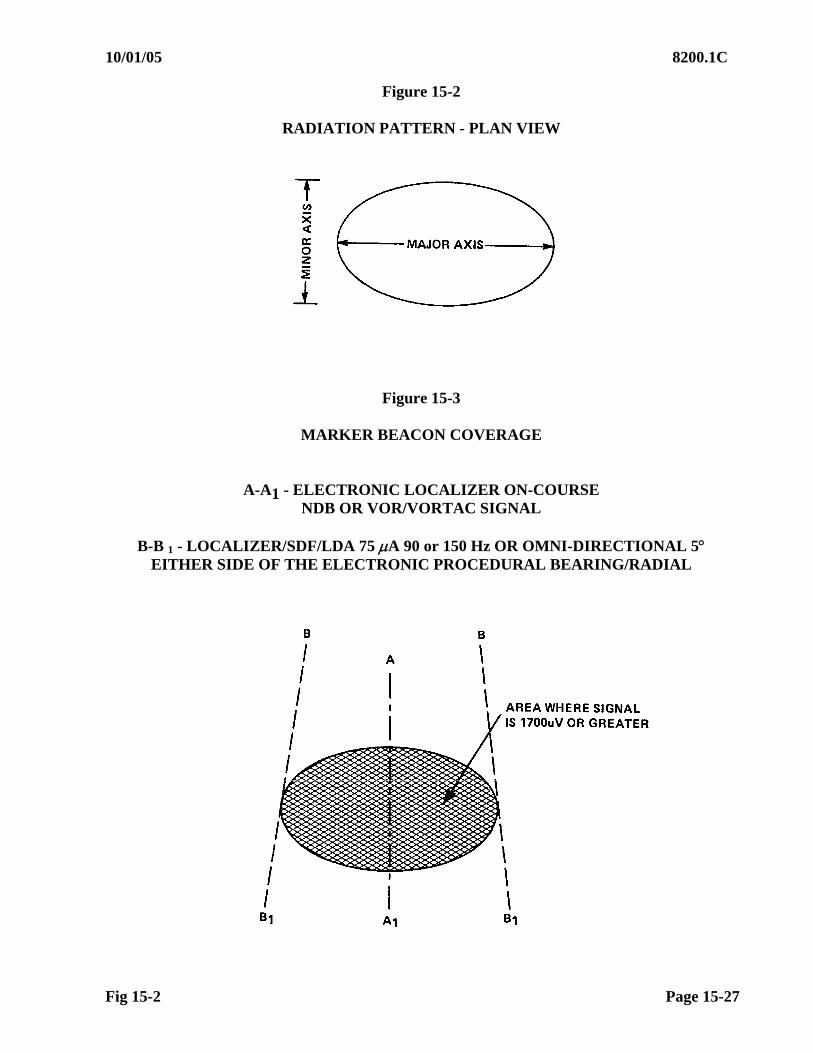
10/01/05 8200.1C
Fig 15-2 Page 15-27
Figure 15-2
RADIATION PATTERN - PLAN VIEW
Figure 15-3
MARKER BEACON COVERAGE
A-A1 - ELECTRONIC LOCALIZER ON-COURSE NDB OR VOR/VORTAC SIGNAL
B-B 1 - LOCALIZER/SDF/LDA 75 A 90 or 150 Hz OR OMNI-DIRECTIONAL 5
EITHER SIDE OF THE ELECTRONIC PROCEDURAL BEARING/RADIAL
8200.1C 5/30/11 Chg 4
Page 15-28 Par 15.20
SECTION 2. LOCALIZER FLIGHT INSPECTION PROCEDURES 15.20 Detailed Procedures – Localizers. Unless otherwise noted, the following procedures apply to all localizers, offset localizers, LDA(s), and SDF(s).
a. Spectrum Analysis. Reserved.
b. Modulation Level. This check measures the modulation of the radiated signal.
Approved Procedure—Front Course. Measure modulation while inbound on the localizer, between 10 miles and 3 miles from the localizer antenna, and on glidepath (at procedural altitude for localizer-only facilities). Preliminary checks may be made when transitioning the “on-course” position during course width and symmetry measurements; however, they must be validated while flying inbound on-course. Some dual frequency antennas do not provide enough clearance power to measure modulation on centerline. For these facilities, measure the clearance-only modulation level while inbound between 5 and 10 off course at the lower standard altitude of 1,500 ft above the antenna or 500 ft above intervening terrain, whichever is higher, with the clearance transmitter in the modulation balance configuration.
Approved Procedure—Back Course. Measure modulation by using the front course flight procedures described above. On single frequency localizers, adjustments to front course modulation will also affect the back course; therefore, adjustments are not required on the back course. Where a separate antenna provides clearance, as well as a back course (such as the waveguide system), modulation checks and adjustments of the clearance transmitter(s) are valid only while on the back course, unless the course transmitter is OFF.
NOTE: Modulation must be measured during the NORMAL configuration clearance checks required by Paragraph 15.20k. Some receivers see excessive modulation as low clearances. Out-of-tolerance modulation must be a basis for restrictions on facilities installed or reconfigured with new type antennas* after January 1, 2000. To implement this requirement, perform a 35 - 35 clearance arc on both transmitters in NORMAL on the front and back course at the first available opportunity. Document the results in the report and facility data sheet. Subsequently, the check needs only to be performed when a 35 - 35 arc in NORMAL is required per the applicable checklist.
*Installed refers to newly commissioned facilities. New type antenna refers to a change from Log Periodic to V-Ring or vice-versa, a change from Capture Effect to Single Frequency or vice-versa, or a change in the number of elements in the antenna array.
c. Modulation Equality. This check is performed to obtain a crosspointer value, which will be used as a reference for phasing.
WARNING HAZARDOUSLY MISLEADING
INFORMATION Misleading information is produced by this configuration. Ensure NOTAM is active. Monitor ATC communications
for improper clearances to other aircraft.WARNING
NOTE: FAA Glide Slopes must be OFF when the Localizer is producing HMI
02/01/07 8200.1C CHG 1
Par 15.20c Page 15-29
Approved Procedure. Position the aircraft as outlined in Paragraph 15.20b, Modulation Level. The angle of descent on an ILS must emulate the commissioned glide path when the glide slope is not radiating. Adjustments to modulation equality will require a subsequent check of course alignment.
d. Power Ratio Check. The purpose of this check is to measure the ratio of power between the course and clearance transmitters of dual frequency localizers. Approved Procedure—Using the Spectrum Analyzer. Position the aircraft on the localizer on-course within 10 miles and in line-of-sight of the antenna or parked on the runway on-course in line-of-sight of the antenna. Compare the relative signal strength of the course and clearance transmitters with the course transmitter in RF power monitor reference and the clearance transmitter in normal.
Approved Procedure—Not Using the Spectrum Analyzer. Position the aircraft on the runway centerline/ on-course at or near the approach end of the runway in line-of-sight of the antenna. Use the AGC meter or equivalent and note the voltage level of the facility in the following configurations:
(1) Course transmitter at RF power monitor reference setting; clearance
transmitter OFF.
(2) Clearance transmitter in normal; course transmitter OFF.
Compute the power ratio using the dual frequency power ratio formula (see Appendix 2).
e. Phasing. The purpose of this check is to determine that the phase relationship between the sideband and carrier energy is optimum. The facility will normally be phased using ground procedures. No specific requirement exists for airborne phasing.
WARNING HAZARDOUSLY MISLEADING
INFORMATION Misleading information is produced by this configuration. Ensure NOTAM is active. Monitor ATC communications
for improper clearances to other aircraft.WARNING
NOTE: FAA Glide Slopes must be OFF when the Localizer is producing HMI Approved Procedure--Front Course. Since antennas vary greatly, obtain the correct azimuth for phasing the facility from Facilities Maintenance personnel. Fly inbound toward the antenna at an altitude and azimuth determined by Maintenance between 10 and 3 miles. Transmit the crosspointer values to assist the ground technician to adjust the phasing. The optimum quadrature phase condition is established when the microampere deflection is the same as that found when checking modulation equality.
Approved Procedure--Back Course. If maintenance requests phasing on the back course, apply the procedures described above.
8200.1C 02/01/07 CHG 1
Page 15-30 Par 15.20f
f. Course Sector Width and Symmetry. The purpose of this check is to establish
and maintain a course sector width and ratio between half-course sectors that will provide the desired displacement sensitivity required at the procedural missed approach point (MAP) or threshold and be within the limitations of the procedural protected area. Approved Procedure. This procedure applies to the front course (and back course if it is used for an approach or missed approach). Measure the course sector width and symmetry between 6 and 10 miles from the localizer antenna at the lower standard altitude of 1,500 ft above the antenna or 500 ft above intervening terrain, whichever is higher. Flight Inspection Policy must approve measurements inside 6 nm. On periodic checks, course width may be checked at distances from 10 to 14 nm from the localizer antenna. Verify any unusual/ out-of-tolerance indications at a distance of 10 nm or less. If the condition repeats, or if unable to verify due to weather or ATC restrictions, take appropriate NOTAM/ restriction action. On periodic checks, higher altitudes may be used, provided a course width comparability check in the normal configuration is made (usually at commissioning) at the lower standard altitude of 1,500 ft above the antenna or 500 ft above intervening terrain, whichever is higher, and a higher altitude is used for the comparison. If comparability results are in tolerance and within 0.2, subsequent inspections may be made at any altitude between the lower and higher altitudes used for comparability. If a comparability check has not been completed, an altitude 1,500 ft above the antenna or 500 ft above intervening terrain, whichever is higher, must be used to evaluate course width. If the commissioned width is changed, reestablish width monitor references at the lower standard altitude of 1,500 ft above the antenna or 500 ft above intervening terrain, whichever is higher. If clearance comparability was satisfactory prior to the course width change, re-check the Procedure 1/ 2 configurations at the lower standard altitude. Further comparability checks at the desired higher altitude are not required if these minimum clearance levels are met.
(1) Basic Method. A crossing, perpendicular to the on-course, must be made in each direction, maintaining a constant airspeed (to average out any wind component) over a checkpoint of a known distance from the localizer antenna, i.e., outer marker, FAF, etc. If ground speed or along-track outputs are available, only one crossing is required. Measure the course sector width and calculate the symmetry (use the appropriate formulas in Appendix 2).
02/01/07 8200.1C CHG 1
Par 15.20f(2) Page 15-31
(2) Theodolite or Tracking Device Method. Position the theodolite or tracking device in accordance with Paragraph 15.11f, Theodolite Procedures. Only one crossing is required at the maximum distance that permits theodolite tracking. Maintain a constant airspeed. Reference the course sector width to the azimuth reference marks of the theodolite (usually spaced 5 apart). Measure the course sector width, using a device such as 10-point dividers, and calculate the symmetry.
NOTE: An RTT may be used to track an aircraft throughout the course sector. Apply the course sector width received to the calibration of the RTT.
(3) Width Requirements. Localizers, offset localizers, and LDA(s) must be
tailored to a course sector width not greater than 6 and a linear sector width of 700 ft at the following points:
(a) Point C for LDA and SDF
(b) Point B for runways less than 4,000 ft long and for runways which do not conform to precision instrument design standards.
(c) Point T for facilities supporting all other applications. The tailoring requirement may be waived for facilities supporting other than CAT II or III operations if tailoring cannot be achieved due to siting constraints, performance derogation etc.; however, the final width must be established as close as possible to the optimum. The justification must be included in the flight inspection report. The decision to have other than a tailored course width is not a flight inspection function and must be made at the applicable Region or comparable military level. If the course sector width on a facility which supports a precision approach will not provide for at least 400 ft linear width at the runway threshold, the course must be restricted as unusable inside the point where the linear width is 400 ft. The commissioned course width of an SDF must be no greater than 12.0. If the course width is adjustable, it must be tailored. Some facilities with course widths less than 3.00 have had problems associated with aircraft overshooting turns to the approach course; pay particular attention to flyability with narrow widths.
g. Course Alignment and Structure. These checks measure the quality and alignment of the on-course signal. The alignment and structure checks are usually performed simultaneously; therefore, use the same procedures to check alignment and structure.
8200.1C 9/14/09 Chg 2
Page 15-32 Par 15.20g(2)
Approved Procedure. This procedure applies to the front course (and the back course) if it is used for an approach or missed approach).
(1) General. Evaluate the course along the designed procedural azimuth from the furthest point required by the type of inspection being conducted throughout the remaining zones. Maintain the published or proposed procedural altitudes through each approach segment until intercepting the glidepath and then descend on the glidepath to Point C or runway threshold.
NOTE: For FAA, U.S. Non-Federal civil, U.S. Army, and U.S. Navy/ Marine Corps facilities, the alignment must meet Maintenance Reference “Initial” tolerances IAW TI 8200.52, Chapter 15, any time alignment is adjusted, or at the end of a Periodic with Monitors inspection.
(a) For a localizer-only approach, the published or proposed
procedural altitudes must be maintained in each segment, except the final segment must be flown as follows: Upon reaching the FAF inbound, descend at a rate of approximately 400 ft per mile (930 ft per minute at 140 knots; 800 ft per minute at 120 knots) to an altitude of 100 ft below the lowest published MDA and maintain this altitude to Point C, which is the MAP.
NOTE: See Appendix 1 definition of Point C for localizer only approaches.
(b) For ILS approaches which support localizer-only minima, the
procedure specified in (a) above must be used in addition to the run on normal glidepath during the following inspections: Site, Commissioning, and Specials for antenna system change, user complaint or site modifications, and on a periodic inspection any time there is a significant deterioration of localizer structure.
(c) For localizers which are aligned along the runway centerline, the aircraft may be positioned along the runway centerline by visual cues or theodolite. When RTT or AFIS equipment is used, the localizer on-course signal must be flown.
(d) Theodolite, RTT, or AFIS must be the method of evaluation for facilities which are not aligned along the runway centerline.
(e) For LDA(s) oriented toward a non-descript point-in-space where adequate visual checkpoints are not available and AFIS runway updates are impractical, the alignment on commissioning-type inspections must be determined using Differential GPS AFIS “truth system”, pseudo runway development or theodolite. Pseudo runway development based on surveyed airport checkpoints (runway ends, taxiways, etc.) must be approved in advance by Flight Inspection Policy. Establish an equality of modulation reference for subsequent alignment and monitor comparison.
During subsequent periodic inspections, where AFIS updates are impractical, the localizer alignment may be determined to be either Satisfactory (S) or Unsatisfactory (U), in lieu of course alignment values (refer to Paragraph 6.14d). If the actual alignment is required (i.e., SOIA), the use of Differential GPS AFIS "truth system", theodolite, or pseudo runway development is required.

9/14/09 8200.1C Chg 2
Par 15.20g(2) Page 15-33
(2) Roll-Out Procedures. The procedures below are required for all Category II/ III localizers. They are also required for all Category I localizers installed with runway lengths of 5,000 ft or greater. Offset localizers, localizers installed without glide slopes, SDF(s), LDA(s), and facilities currently with a classification of I/ A, B, or C, need not be checked. Rollout checks and the 50 ft ILS-3 comparison checks are required on both transmitters.
(a) Site, Commissioning, Reconfiguration and Categorization Inspections of centerline oriented facilities. Use the procedures in Paragraph 15.20g(1) until reaching Point C. Cross Point C at 100 ft, runway threshold at approximately 50 ft, and continue on the extended glidepath angle to the touchdown point. Continue the landing roll and determine the actual course alignment for ILS Zones 4 and 5. Measure the course structure from the actual alignment. If the actual alignment for Zones 4 and 5 cannot be determined using this method, taxi the aircraft along the runway centerline from abeam the glide slope to Point E. Record the raw crosspointer information and mark, abeam the glide slope, Point D and Point E. Manually calculate the actual course alignment and structure for each of the required zones. This is also a comparison check intended to authorize the 50 ft run as a periodic check of Zone 4 and 5 structure. A comparison of structure results found on Rollout and on the 50 ft ILS-3 run is needed to determine if the expedient method of checking Zones 4 and 5 structure on the 50 ft run is valid for periodic checks. Satisfactory comparability must be defined as 3 A or less difference between the results in each zone with both Rollout and 50 ft results being in-tolerance for that zone. Maximum structure in either zone does not have to occur at the same point on the runs to be comparable. Apply the 95% rule as specified in Paragraph 15.51a to results outside normal tolerance. The Zone 4 and Zone 5 structure analysis determined during Rollout procedures is the definitive pass/ fail criteria, taking precedence over the results of the 50 ft ILS-3 maneuver. Document the Rollout and ILS-3 50 ft structure comparability results IAW Order 8240.36, Appendix 8. Submit FAA Form 8240-20, AVNIS Data Change Submission, to the Aviation System Standards Flight Inspection Policy to effect ILS Classification changes to the National Flight Data Center (NFDC). When the Rollout check is found satisfactory on a Category I ILS and the comparability check is unsatisfactory, Flight Inspection Policy must contact the National Flight Procedures Office Procedures Specialist and the regional All-Weather Operations representative to determine if any users are authorized IFR use below Category I minima. Flight Inspection Policy will make the final determination as to the requirement for future Zone 4 and 5 rollouts on that facility, and transmit the appropriate ILS classification to NFDC. Refer to the Rollout flow chart and associated Rollout code legend for the Zones 4 and 5 structure comparison process.
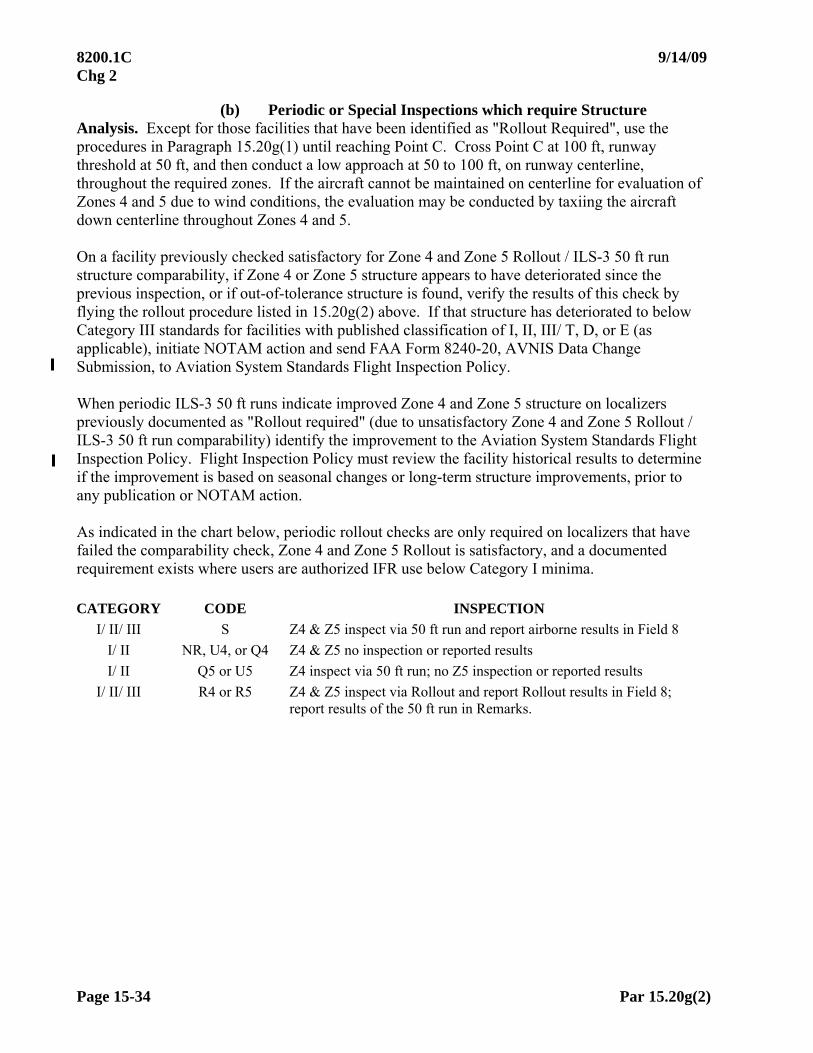
8200.1C 9/14/09 Chg 2
Page 15-34 Par 15.20g(2)
(b) Periodic or Special Inspections which require Structure Analysis. Except for those facilities that have been identified as "Rollout Required", use the procedures in Paragraph 15.20g(1) until reaching Point C. Cross Point C at 100 ft, runway threshold at 50 ft, and then conduct a low approach at 50 to 100 ft, on runway centerline, throughout the required zones. If the aircraft cannot be maintained on centerline for evaluation of Zones 4 and 5 due to wind conditions, the evaluation may be conducted by taxiing the aircraft down centerline throughout Zones 4 and 5. On a facility previously checked satisfactory for Zone 4 and Zone 5 Rollout / ILS-3 50 ft run structure comparability, if Zone 4 or Zone 5 structure appears to have deteriorated since the previous inspection, or if out-of-tolerance structure is found, verify the results of this check by flying the rollout procedure listed in 15.20g(2) above. If that structure has deteriorated to below Category III standards for facilities with published classification of I, II, III/ T, D, or E (as applicable), initiate NOTAM action and send FAA Form 8240-20, AVNIS Data Change Submission, to Aviation System Standards Flight Inspection Policy. When periodic ILS-3 50 ft runs indicate improved Zone 4 and Zone 5 structure on localizers previously documented as "Rollout required" (due to unsatisfactory Zone 4 and Zone 5 Rollout / ILS-3 50 ft run comparability) identify the improvement to the Aviation System Standards Flight Inspection Policy. Flight Inspection Policy must review the facility historical results to determine if the improvement is based on seasonal changes or long-term structure improvements, prior to any publication or NOTAM action. As indicated in the chart below, periodic rollout checks are only required on localizers that have failed the comparability check, Zone 4 and Zone 5 Rollout is satisfactory, and a documented requirement exists where users are authorized IFR use below Category I minima. CATEGORY CODE INSPECTION
I/ II/ III S Z4 & Z5 inspect via 50 ft run and report airborne results in Field 8
I/ II NR, U4, or Q4 Z4 & Z5 no inspection or reported results
I/ II Q5 or U5 Z4 inspect via 50 ft run; no Z5 inspection or reported results
I/ II/ III R4 or R5 Z4 & Z5 inspect via Rollout and report Rollout results in Field 8; report results of the 50 ft run in Remarks.
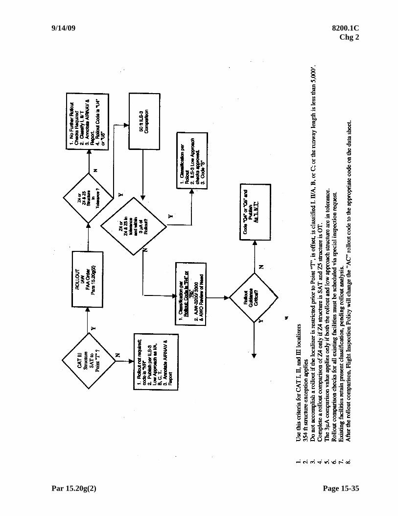
9/14/09 8200.1C Chg 2
Par 15.20g(2) Page 15-35
8200.1C 9/14/09 Chg 2
Page 15-36 Par 15.20g(2)
Aviation System Standards Flight Inspection Policy assigns the following codes to AVNIS facility data sheets to indicate Localizer eligibility for a Rollout check:
NR = Check is not required.
AC = Awaiting Rollout Check Flight inspectors assign the following codes on the flight inspection report and via FAA Form 8240-20 to change AVNIS facility data sheets to indicate the status of Rollout checks:
S = Rollout accomplished; results of both the Rollout and the 50 ft run are within
Category III tolerance and compare within 3 A. U4 = Rollout accomplished; Zone 4 results do not meet Category II/ III tolerances. U5 = Rollout accomplished; Zone 5 results do not meet Category III tolerances. R4 = Rollout required for evaluation of Zone 4 and Zone 5. Rollout was
accomplished; ground results meet Category II/ III requirements but do not compare with results of the 50 ft run in Zone 4.
R5 = Rollout required only for evaluation of Zone 5. Rollout was accomplished;
ground results meet Category III requirements; comparison with the 50 ft run was Satisfactory in Zone 4 but Unsatisfactory in Zone 5. Aviation System Standards Flight Inspection Policy assigns the following codes to the AVNIS facility data sheets post flight inspection after contact with the National Flight Procedures Office Procedures Specialist and regional All-Weather Operations representative:
Q4 = Periodic Rollout not required. Rollout accomplished; results meet Category II/ III requirements, but Zone 4 ground results do not compare with results of the 50 ft run. This code means that future evaluations of Zone 4 and Zone 5 must be through a Rollout Check but that it need not be done on periodic inspections, as these zones are not currently used for IFR. This code is only applied by the Aviation System Standards Flight Inspection Policy and does not apply to Category III. Application to Category II is only appropriate IAW Order 8200.1, Paragraph 15.20g(3) Note 2.
Q5 = Periodic Rollout not required. Rollout accomplished; results meet Category II/ III requirements, but Zone 5 ground results do not compare with results of the 50 ft run. This code means that future evaluations of Zone 5 must be through a Rollout Check but that it need not be done on periodic inspections, as these zones are not currently used for IFR. This code is applied only by Aviation System Standards Flight Inspection Operations Office and is only used to easily display the non-comparable zone.

02/01/07 8200.1C CHG 1
Par 15.20g(3) Page 15-37
(3) Zones to be inspected for structure. All ILS localizers sited on the extended runway centerline must be inspected and analyzed through Zones 1, 2, 3, 4, and 5 (runways less than 5,000 ft long do not have Zone 5) on all inspections requiring alignment or structure validation. These localizers must be classified according to the furthest point at which the structure conforms to Category III tolerance. Specific reporting instructions are contained in Order 8240.36. This classification is for autoland authorization. Other facilities must be inspected and analyzed in Zones 1, 2, and 3. See Appendix 1 and Figure 15-1 for zone identification.
Type Approach/ Facility Zones Required for Unrestricted Service (1)
Category III Zones 1, 2, 3, 4, 5 Category II ILS Zones 1, 2, 3, and 4 (see Paragraph 5.12j(9) Category I ILS Zones 1, 2, 3 Other types of facilities or approaches Zones 1, 2, 3
NOTE 1: During site, commissioning, reconfiguration, categorization, antenna, and/or frequency change inspectioncheck all of Zone 1. All other inspections (i.e., periodic, periodic with monitors, etc.) evaluate structure from GSI or the FAF (whichever is further) through all other required zones. For After Accident Inspections, see Paragraph 4.14g.
NOTE 2: Category II localizers failing to meet structure tolerance in Zone 4 will not be shown as restricted on the flight inspection report; however, a NOTAM will be issued. See Chapter 5, Section 1.
(4) Alignment Areas. Determine the course alignment in the following areas:
Front Course From To
CAT I, II, III One mile from runway threshold Runway threshold ILS Zone 4 Runway threshold Point D ILS Zone 5 Point D Point E
Offset Localizers One mile from runway threshold Runway threshold or abeam runway threshold
LDAs and SDFs One mile from Point C Point C
Back Course All Types of Facilities Two miles from the antenna One mile from the antenna
NOTE: When a restriction occurs in an area where alignment is normally analyzed, measure alignment through manual or AFIS analyzation of the average course signal in the following areas:
From To
One mile from the start of the restriction The start of the restriction.

8200.1C 10/01/05
Page 15-38 Par 15.20h
h. Glide Slope Signal on Localizer Back Course. Evaluation of localizer back course approaches must also include an evaluation for active glide slope signals. Glide slope signals that result in flag or CDI activity must be cause for immediate action to alert pilots to disregard all glidepath indications on the back course approach (i.e., NOTAM). Ensure the alert will be printed on the localizer back course instrument approach chart.
i. Monitor References. The inspector must ensure that the facility is set at the monitor reference prior to each check. Monitor references must be checked IAW Paragraph 15.12a(3) when prescribed by the checklist and when applicable on special inspections. At the conclusion of any width monitor inspection, return the facility to normal, and check and report the resulting course sector width and symmetry. Approved Procedure—Width Reference. Use the flight procedure and methods described in Paragraph 15.20(f). At the conclusion of any width monitor inspection, return the facility to normal, and check and report the resulting course sector width and symmetry. Approved Procedure—Alignment Reference. This check is performed to assure that the monitors will detect a specific shift of the localizer course, and must only be accomplished upon special request from the FAA region or appropriate military authority. This check may be accomplished on the front course without the waveguide transmitter radiating or on the back course, using the procedures described in Paragraph 15.20g. It is not necessary to verify ground alignment monitor checks in the air or to verify airborne alignment monitor checks on the ground. Request the course be misaligned to the monitor alarm limits each side (90 Hz/ 150 Hz) of the operational course. Both the recorder and the visual display must be used to verify course alignment shifts. During any inspection, the monitor limits must be referenced to the designed on-course alignment according to facility category.
(1) Ground. After the airborne localizer alignment has been determined, position the aircraft near the runway threshold where the stable crosspointer is received. The aircraft may be displaced as much as 75A from the on-course signal. (This option is authorized, providing the sensitivity of the course sector width is linear.) The received course indication must be referenced to the alignment found airborne. Request that maintenance shift the course to both of the monitor limit points and then return to normal.
At facilities that are installed offset to the runway, the alignment monitor limits may be established with the aircraft on the ground within 75A of the on-course signal; but the aircraft must not be positioned closer than 3,000 ft from the antenna array. If these two conditions cannot be met, perform this check in the air. If monitors are initially checked on the ground and alignment is then adjusted based on airborne analysis, a monitor re-check is not required, providing the following criteria are met:
In-tolerance flag/ modulation and AGC exist.
Crosspointer is stable.
Crosspointer data are recorded as found during adjustment and at the final setting.

02/01/07 8200.1C CHG 1
Par 15.20i Page 15-39
The monitor shift on the ground, when applied to the new airborne alignment, is in tolerance.
Monitor settings are not changed after the alignment is adjusted.
(2) Airborne. Perform airborne alignment monitor checks while inbound on the designed procedural azimuth (on localizers aligned along runway centerline, the aircraft should be aligned with the centerline extended). Measure the alignment shifts to monitor limits by recording the instantaneous course displacements or course shifts as referenced to runway centerline extended. If feasible, this may be accomplished on one run during which both limit points and a return to normal are recorded.
(3) Equality of Modulation. When course alignment is satisfactory and a monitor inspection is required, localizers may be evaluated for monitor references using equality of modulation method. This method may be used on all categories of localizers with the concurrence of maintenance personnel. All facilities must be flown to establish the alignment in a normal operating configuration. Once the alignment has been established, maintenance will set up an equality of modulation configuration. The equality used to establish the alignment will become the reference for the subsequent monitor readings. When requested, maintenance personnel will unbalance the modulation to achieve the monitor reference point. Measure the displacement in microamps, repeat the procedure in the other direction, then restore to normal. This may be accomplished in the air or on the ground and need not be performed on centerline. Use of this method will be noted in the remarks section of the flight inspection report.
WARNING
HAZARDOUSLY MISLEADING INFORMATION
Misleading information is produced by this configuration. Ensure NOTAM is active. Monitor ATC communications
for improper clearances to other aircraft.WARNING
NOTE: FAA Glide Slopes must be OFF when the localizer is producing HMI
j. RF Power Monitor Reference. This inspection is conducted to determine that the
localizer meets specified tolerances throughout the service volume while operating at reduced power. Approved Procedure. This procedure applies to the front course (and the back course if it is used for an approach or missed approach). This check must be conducted with the facility operating at reduced power. Check for interference, signal strength, clearances, flag alarm, identification, and structure as follows. Steps:
(1) Fly an arc across the localizer course at 18 miles* from the antenna at 4,500 ft above antenna elevation throughout Sector 1.

8200.1C 02/01/07 CHG 1
Page 15-40 Par 15.20j(2)
(2) Fly an arc across the localizer course at 18 miles* from the antenna at 2,000 ft above the threshold elevation or 1,000 ft above intervening terrain, whichever is higher. If 1,000 ft above intervening terrain is higher than 4,500 ft above antenna elevation, the localizer must be restricted. Determine a distance where terrain clearance is within the SSV for a localizer restriction distance. The facility must have an ESV for use outside the SSV.
(3) Proceed on course, inbound from 18 miles*, until reaching 7 above the horizontal (measured from the localizer antenna) or Point C, whichever occurs last, at 2,000 ft above threshold elevation, or 1,000 ft above intervening terrain, whichever is higher.
(4) Fly an arc throughout Sectors 1 and 2 (and 3, if procedurally required) across the localizer course 1,500 ft above the antenna or 500 ft above intervening terrain, whichever is higher, at 10 miles** from the antenna. Altitude is intended to be single altitude. If unable to maintain minimum terrain clearance within the SSV, restrict the facility accordingly.
NOTE: See Chapter 22 for additional ESV requirements. If the ESV altitude is within the SSV distance, special consideration will be applied to localizer support.
* 25 miles from the antenna for ICAO Service Volumes. ** 17 miles from the antenna for ICAO Service Volumes.
k. Clearance. Clearances are measured to ensure that the facility provides adequate
off-course indications throughout the service volume (or ESV, whichever is greater). Approved Procedure. This check applies to the front course (and the back course if it is used for an approach or missed approach). The clearance orbit will be conducted at a radius between 6 to 10 miles from the antenna at the lower standard altitude of 1,500 ft above the antenna or 500 ft above intervening terrain, whichever is higher. On periodic checks, clearances may be checked to a distance of 14 nm from the localizer antenna. Verify any unusual/ out-of-tolerance indications at a distance of 10 nm or less. If the condition repeats, or if unable to verify due to weather or ATC restrictions, take appropriate NOTAM/ restriction action.
(1) Clearance Comparability. In some cases it may be necessary to perform clearance measurements at altitudes higher than the lower standard altitude of 1,500 ft above the antenna or 500 ft above intervening terrain, whichever is higher (e.g., weather, restricted airspace, or ATC limitation). After commissioning, higher altitudes may be used, provided a comparability check is made (usually at commissioning) documenting clearances at the lower standard altitude of 1,500 ft above the antenna or 500 ft above intervening terrain, whichever is higher, and the higher altitude. If comparability results are satisfactory, subsequent inspections may be made at any altitude between the lower and higher altitudes used for comparability. If a comparability check has not been completed satisfactorily, altitudes above the lower standard altitude of 1,500 ft above the antenna or 500 ft above intervening terrain, whichever is higher, must not be used to evaluate clearances.
02/01/07 8200.1C CHG 1
Par 15.20k(1) Page 15-41
On commissioning/ reconfiguration type checks, to include new type antenna installations/ replacements, this comparison must be accomplished.
NOTE: The lower altitude is recommended and should be attempted on all inspections. Clearance checks above the lower standard altitude of 1,500 ft above the antenna or 500 ft above intervening terrain, whichever is higher, should be the exception.
The difference between Procedures 1 and 2 involve airborne analysis only. Procedure 1 will be used for all facilities, unless the lowest clearance condition configuration at the desired higher altitude produces higher clearances better than the same configuration at the lower standard altitude. Procedure 2 allows slightly higher clearances at the desired higher altitude. However, Procedure 2 can only be used if the more stringent clearance tolerances are applied at the lower standard altitude. See the clearance comparability flow charts in this paragraph for clarification. Comparability is required in unrestricted areas of coverage and on one transmitter only. If comparability is unsatisfactory, clearly document the reason.
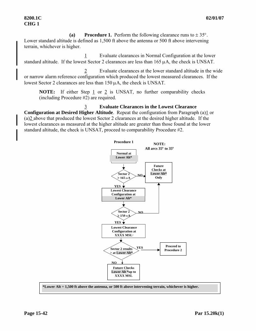
8200.1C 02/01/07 CHG 1
Page 15-42 Par 15.20k(1)
(a) Procedure 1. Perform the following clearance runs to 35. Lower standard altitude is defined as 1,500 ft above the antenna or 500 ft above intervening terrain, whichever is higher.
1 Evaluate clearances in Normal Configuration at the lower standard altitude. If the lowest Sector 2 clearances are less than 165 A, the check is UNSAT.
2 Evaluate clearances at the lower standard altitude in the wide or narrow alarm reference configuration which produced the lowest measured clearances. If the lowest Sector 2 clearances are less than 150 A, the check is UNSAT.
NOTE: If either Step 1 or 2 is UNSAT, no further comparability checks (including Procedure #2) are required.
3 Evaluate Clearances in the Lowest Clearance Configuration at Desired Higher Altitude. Repeat the configuration from Paragraph (a)1 or (a)2 above that produced the lowest Sector 2 clearances at the desired higher altitude. If the lowest clearances as measured at the higher altitude are greater than those found at the lower standard altitude, the check is UNSAT, proceed to comparability Procedure #2.
Lowest Clearance Configuration at
XXXX MSL*
NOTE: All arcs 35 to 35
Normal at Lower Alt*
Lowest Clearance Configuration at
Lower Alt*
Sector 2 150 A
Sector 2 results > at Lower Alt*
Sector 2 165 A
NO
NO
NO
YES
YES
Procedure 1
Future Checks Lower Alt *up to
XXXX MSL
YES
Future Checks at
Lower Alt* Only
*Lower Alt = 1,500 ft above the antenna, or 500 ft above intervening terrain, whichever is higher.
Proceed to Procedure 2
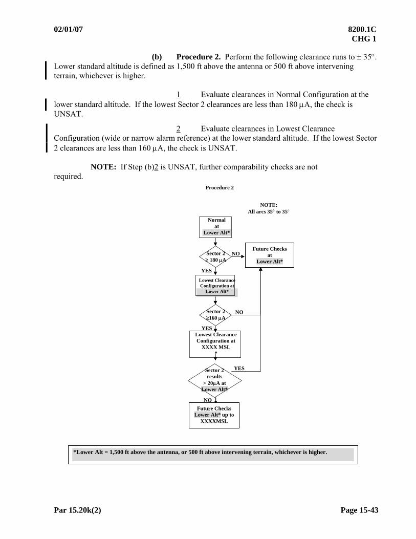
02/01/07 8200.1C CHG 1
Par 15.20k(2) Page 15-43
(b) Procedure 2. Perform the following clearance runs to 35. Lower standard altitude is defined as 1,500 ft above the antenna or 500 ft above intervening terrain, whichever is higher.
1 Evaluate clearances in Normal Configuration at the lower standard altitude. If the lowest Sector 2 clearances are less than 180 A, the check is UNSAT.
2 Evaluate clearances in Lowest Clearance Configuration (wide or narrow alarm reference) at the lower standard altitude. If the lowest Sector 2 clearances are less than 160 A, the check is UNSAT.
NOTE: If Step (b)2 is UNSAT, further comparability checks are not required.
Procedure 2
Lowest Clearance Configuration at
XXXX MSL *
Lowest Clearance Configuration at
Lower Alt*
Normal at
Lower Alt*
Sector 2160 A
Sector 2 results
> 20A at Lower Alt*
Sector 2 180 A
NO
NO
NO
YES
Future Checks Lower Alt* up to
XXXXMSL
NOTE: All arcs 35 to 35
YES
YES
Future Checks at
Lower Alt*
*Lower Alt = 1,500 ft above the antenna, or 500 ft above intervening terrain, whichever is higher.

8200.1C 5/30/11 Chg 4
Page 15-44 Par 15.20k(1)
3 Evaluate Clearances in the Lowest Clearance Configuration at Desired Higher Altitude. Repeat the configuration from Paragraph (b)1 or (b)2 above that produced the lowest Sector 2 clearances at the desired higher altitude. If the lowest clearances measured at the higher altitude are more than 20 A greater than those found at the lower standard altitude, the check is UNSAT, and subsequent checks must be conducted at the lower standard altitude of 1,500 ft above the antenna or 500 ft above intervening terrain, whichever is higher.
NOTE: The normal or alarm reference condition that causes the lowest clearances will not always be a periodic monitor check condition. Document the flight inspection report and the data sheet with the configuration that produces the lowest clearance values. Inspections to remove a restriction based on clearances must include a check of all clearance commissioning configurations. See Paragraph 15.12a(7).
(c) Additional Clearance Comparability Requirements. If Procedure 1 or 2 clearance comparability is SAT, perform the following checks on one transmitter for historical reference.
1 Course and Clearance Transmitters Wide (dual frequency)/
Course Transmitter Wide (single frequency) at the lower standard altitude of 1,500 ft above the antenna or 500 ft above intervening terrain, whichever is higher.
2 Course and Clearance Transmitters Wide (dual frequency)/ Course Transmitter Wide (single frequency) at Desired Higher Altitude.
3 Normal Configuration at the Desired Higher Altitude (if this altitude is different from the Paragraph 15.20k(3) High Angle Clearance Check).
NOTE: Evaluate the configurations in 2 and 3 above only if Procedure 1 or 2 clearance comparability is SAT.
COMMISSIONING TYPE CLEARANCE CHECKS
*Lower Alt = 1,500 ft above the antenna, or 500 ft above intervening terrain, whichever is higher.
(2) Inspections
(a) Commissioning. Check clearances in both the normal and the monitor limit configurations described in the appropriate checklist.
.
High Angle 4500 ft above
LOC
Normal at XXXX MSL
Wide (Single Freq)
Lower Alt* and XXXX MSL
Wide/Wide (Dual Freq)
Lower Alt* and XXXX MSL
Normal at
Lower Alt*

5/30/11 8200.1C Chg 4
Par 15.20k(2) Page 15-45
(b) Facilities documented with Procedure 2 comparability must be re-checked at the lower standard altitude of 1,500 ft above the antenna or 500 ft above intervening terrain, whichever is higher, when clearances are found at less than 160 A in any configuration on any periodic check. If the re-check at lower standard altitude is satisfactory, the comparability check must be reaccomplished, or higher altitudes will not be used to check clearances.
(c) Verify clearances at the lower standard altitude of 1,500 ft above the antenna or 500 ft above intervening terrain, whichever is higher, at least every 1,080 days. This check determines if environmental changes affect clearances at the lower standard altitude of 1,500 ft above the antenna or 500 ft above intervening terrain, whichever is higher, while not affecting clearances at the higher altitudes. Fly one clearance run (normal or monitor reference) at the lower standard altitude of 1,500 ft above the antenna or 500 ft above intervening terrain, whichever is higher. Values less than 200 A may indicate a potential clearance problem; however, if the minimum clearances required to authorize checks at higher altitudes are maintained at the lower standard altitude, higher altitudes may continue to be used.
(3) High Angle Clearance. This check determines that the transmitted signals provide proper off-course indications at the upper limit of the service volume and must be conducted during a site evaluation, commissioning inspection, or when a change in location, height, or type of antenna is made. Approved Procedure. This check applies to the front course (and the back course if it is used for an approach or missed approach). This check is only required on one transmitter.
(a) Fly a 10-mile arc through Sectors 1 and 2 (and 3, if procedurally required), at 4,500 ft above the antenna.
(b) If clearances are out-of-tolerance, additional checks will be made at decreasing altitudes to determine the higher altitude at which the facility may be used.
l. Coverage. Coverage must be evaluated concurrently with each required check during all inspections.
m. Reporting Fixes, SID(s)/ DP(s) STAR(s), and Profile Descents. Refer to Figure 15-4. The localizer, SDF, or LDA may be used to support fixes, or departure, en route, and arrival procedures. Under these circumstances, navigation is accomplished by using some other facility such as VOR or an NDB. Facility performance of all facilities involved must be checked to ensure that all coverage parameters are within tolerance. This must be accomplished during a commissioning inspection, when new procedures are developed or redescribed, or on appropriate special inspections (e.g., user complaints). When fixes are located within the RHO-THETA FISSV and ILS SSV (see definitions in Appendix 1), coverage throughout the fix displacement area can be predicted (fix displacement evaluation is not required).
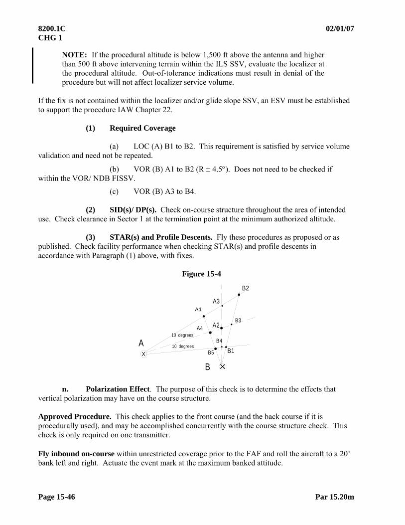
8200.1C 02/01/07 CHG 1
Page 15-46 Par 15.20m
NOTE: If the procedural altitude is below 1,500 ft above the antenna and higher than 500 ft above intervening terrain within the ILS SSV, evaluate the localizer at the procedural altitude. Out-of-tolerance indications must result in denial of the procedure but will not affect localizer service volume.
If the fix is not contained within the localizer and/or glide slope SSV, an ESV must be established to support the procedure IAW Chapter 22.
(1) Required Coverage
(a) LOC (A) B1 to B2. This requirement is satisfied by service volume validation and need not be repeated.
(b) VOR (B) A1 to B2 (R 4.5). Does not need to be checked if within the VOR/ NDB FISSV.
(c) VOR (B) A3 to B4.
(2) SID(s)/ DP(s). Check on-course structure throughout the area of intended use. Check clearance in Sector 1 at the termination point at the minimum authorized altitude.
(3) STAR(s) and Profile Descents. Fly these procedures as proposed or as published. Check facility performance when checking STAR(s) and profile descents in accordance with Paragraph (1) above, with fixes.
Figure 15-4
B2
A1
A2
X
X
B1
A3
A4
B5
B4
B3
10 degrees
10 degrees
A
B
n. Polarization Effect. The purpose of this check is to determine the effects that vertical polarization may have on the course structure. Approved Procedure. This check applies to the front course (and the back course if it is procedurally used), and may be accomplished concurrently with the course structure check. This check is only required on one transmitter. Fly inbound on-course within unrestricted coverage prior to the FAF and roll the aircraft to a 20 bank left and right. Actuate the event mark at the maximum banked attitude.
02/01/07 8200.1C CHG 1
Par 15.20o Page 15-47
o. Identification and Voice. This check is made to ensure identification and voice (if installed) is received throughout the coverage area of the localizer. SDF(s) have a three-letter coded identifier. Localizers and LDA(s) have a three-letter coded identifier preceded by the code letter I. Approved Procedure. This procedure is applicable to the front course (and the back course if it is procedurally used). Record the identification during all checks. Check voice transmissions when on-course and at the maximum distance at which course structure is being evaluated. A localizer must be restricted if identification cannot be received in all areas of required coverage. A localizer must not be restricted solely because the voice/ ATIS cannot be received. In this event, advise the procedures specialist and/or Air Traffic Operations personnel.

8200.1C 02/01/07 CHG 1
Page 15-48 Par 15.30
SECTION 3. GLIDE SLOPE FLIGHT INSPECTION PROCEDURES 15.30 Detailed ProceduresGlide Slope.
a. Spectrum Analysis. (Reserved)
b. Modulation Level. This check measures the modulation of the radiated signal.
Approved Procedure. Measure the modulation of the glidepath while inbound on the localizer/ glidepath course between 7 and 3 miles from the glide slope antenna with a signal strength of
150 V or greater. c. Modulation Equality. This check establishes the balance of the carrier signals.
This check should be made prior to any phasing checks and will be used as the reference for phasing.
WARNING HAZARDOUSLY MISLEADING
INFORMATION Misleading information is produced by this configuration. Ensure NOTAM is active. Monitor ATC communications
for improper clearances to other aircraft.WARNING
NOTE: FAA Localizers must be OFF when Glide Slopes are transmitting HMI.
Approved Procedure. Have maintenance personnel configure the facility to radiate carrier signal only. When checking capture effect facilities, the primary transmitter radiates this configuration while the clearance transmitter is off or in dummy load. Use the procedure described in Paragraph 15.30b, Modulation Level. While descending, call out the balance to Facilities Maintenance personnel. Zero A is optimum. An imbalance in excess of 5A must be adjusted towards optimum.
d. Phasing. This check determines that the correct carrier and sideband-only phase relationship are distributed to the antennas.
WARNING HAZARDOUSLY MISLEADING
INFORMATION Misleading information is produced by this configuration. Ensure NOTAM is active. Monitor ATC communications
for improper clearances to other aircraft.WARNING
NOTE: FAA Localizers must be OFF when Glide Slopes are transmitting HMI

02/01/07 8200.1C CHG 1
Par 15.30d Page 15-49
Approved Procedure. Phasing may be performed on the ground (by maintenance) or in the air. Consult the appropriate checklist in Paragraph 15.12h. Proceed inbound from 10 miles from the glide slope antenna along the localizer procedural ground track at 1/3 to 1/2 of the glidepath angle. Maintain this angular descent until reaching runway threshold. Do not make facility adjustments inside 4 miles during the angular descent. Record the crosspointer throughout the phasing run. The flight inspection technician should relay the microammeter indications to the Facilities Maintenance personnel. Have maintenance adjust the phaser until the crosspointer is approximately the same value found during the modulation equality check.
Analysis. Analyze the crosspointer trace during the descent. If the microammeter value varies from the average between 1/2 mile from the threshold and runway threshold, the antenna offset may be incorrect and should be checked (antenna offset is most accurately established and set by maintenance).
NOTE: A comparison of airborne and ground phasing data should be made by maintenance personnel in order to determine if optimum phasing has been established.
(1) Null Reference Phasing. Make the following checks and phase the facility
in the configurations listed below: Sidebands Radiating in Quadrature to Carrier. Perform the maneuver described in “Approved Procedure” above.
(2) Sideband Reference Phasing. Make the following checks and phase the facility in the configuration listed below:
(a) Upper Antenna Feed in Dummy Load. Have Facilities Maintenance personnel insert a 90 section in the main sideband line. Conduct a level run at 1,000 ft above site elevation between 10 to 5 miles from the glide slope antenna. Adjust the phaser to the value found during the modulation equality check. When phasing is completed, remove the 90 section and check for fully fly-down signal. This indicates that the lower antenna sensing is correct. If full fly-up signal is indicated, sensing is incorrect and the facility must be adjusted.
(b) Radiate Upper and Lower Antennas with a 90-degree section in the Main Sideband Phaser. Use the procedure described in Paragraph 15.30d, Phasing. Have maintenance adjust the upper antenna phaser to the value found during the modulation equality check. When this value is attained, remove the 90 section from the main sideband line. Ensure that a fly-up signal is received when the aircraft is below the glidepath.

8200.1C 02/01/07 CHG 1
Page 15-50 Par 15.30d(3)
(3) Capture Effect. Capture effect glide slopes are normally phased on the ground by maintenance personnel; however, they may request airborne phasing. The airborne phase verification procedure must be accomplished on commissioning inspections and when requested by maintenance. This procedure confirms that correct phasing has been achieved.
(a) Airborne Phase Verification Procedure. This procedure helps maintenance to determine if proper phasing exists. Both transmitters may be checked if standby equipment is installed.
Airborne Phase Verification Procedures
PARAMETER
Steps Checks
Mod
ula
tion
Wid
th
Ang
le
Sym
met
ry
Str
uct
ure
Bel
ow
Pat
h
Cle
aran
ce
Pat
h S
tru
ctu
re
(a) Modulation (7) X
(b) Modulation Equality (7) X
(c) Normal Configuration (8) X (1) (2) X X (6a) X
(d) Main Sideband Phaser Dephased Advance* Retard* (8)(9)
(3) (3)
(4) (4)
X X
(e) Middle Antenna Phaser Dephased Advance* Retard* (8)
(3) (3)
(5) (5)
X X
(6b) (6b)
(f) Normal (8) X X X X
FOOTNOTES:
(1) Adjust glidepath width to 0.70 0.03. (2) Facility must be adjusted to within 0.05 of commissioned angle for commissioning type inspections. (3) Width 0.1 sharper or 0.2 wider than normal. (4) Angle 0.1. (5) Angle .05. (6) ClearanceAt a recommended angle of 1.0 from 4 miles to runway threshold, maintaining at least the minimum microamp level. If obstruction clearance is a limiting factor, an acceptable higher fixed angle may be used.
(a) 180 A or better. (b) 150 A or better
(7) Maintenance request
(8) Clearance transmitter is energized throughout steps (c) – (f).
Footnotes (3), (4), (5), and (6) are expected results only. The tolerances in Paragraph 15.60b apply. The Maintenance Reference “INITIAL” tolerances (Order VN200 8240.52) apply if establishing a reference.
* Actual degrees advance or retard to be determined by Maintenance.
(9) Required on commissioning checks; may be accomplished at Maintenance Request on other type checks.

02/01/07 8200.1C CHG 1
Par 15.30d(3)(b) Page 15-51
(b) Airborne Phasing. When airborne phasing is requested, use the procedure described in Paragraph 1 or 2 below, or other alternate procedures specified by maintenance. Facilities Maintenance personnel must determine which procedure is to be used.
1 Airborne Phasing Procedure No.1. Confirm that maintenance has established normal carrier sideband ratios and that ground phasing is complete.
NOTE: The clearance transmitter is de-energized throughout Steps (1)-(4).
Airborne Phasing Procedure No. 1
Steps Type Check Reference Paragraph Configuration Unit of Interest
(1) Modulation Level 15.30b Carrier Only In Tolerance
(2) Modulation Equality
15.30c Carrier Only Crosspointer 0A 5A
(3) Phasing 15.30d Upper to Middle Antenna Lower AntennaDummy Load Middle AntennaRadiate Carrier + Sidebands Upper AntennaRadiate Sidebands Main Sideband PhaserQuadrature
Crosspointer centered about the value found in step (2).
(4) Phasing 15.30d Lower to Upper and Middle Antenna Lower AntennaRadiate Carrier + Sidebands Middle AntennaRadiate Carrier + Sidebands Upper AntennaRadiate Sidebands Main Sideband PhaserQuadrature
Same as above.
(5) Phase Verification
15.30d(3)(a) Steps (c)-(f)
Clearance Transmitter Energized
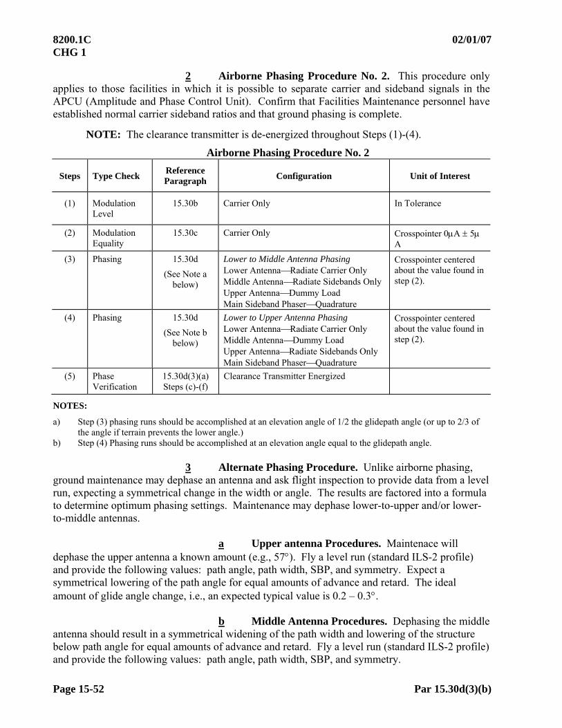
8200.1C 02/01/07 CHG 1
Page 15-52 Par 15.30d(3)(b)
2 Airborne Phasing Procedure No. 2. This procedure only applies to those facilities in which it is possible to separate carrier and sideband signals in the APCU (Amplitude and Phase Control Unit). Confirm that Facilities Maintenance personnel have established normal carrier sideband ratios and that ground phasing is complete.
NOTE: The clearance transmitter is de-energized throughout Steps (1)-(4).
Airborne Phasing Procedure No. 2
Steps Type Check Reference Paragraph Configuration Unit of Interest
(1) Modulation Level
15.30b Carrier Only In Tolerance
(2) Modulation Equality
15.30c Carrier Only Crosspointer 0A 5A
(3) Phasing 15.30d
(See Note a below)
Lower to Middle Antenna Phasing Lower AntennaRadiate Carrier Only Middle AntennaRadiate Sidebands Only Upper AntennaDummy Load Main Sideband PhaserQuadrature
Crosspointer centered about the value found in step (2).
(4) Phasing 15.30d
(See Note b below)
Lower to Upper Antenna Phasing Lower AntennaRadiate Carrier Only Middle AntennaDummy Load Upper AntennaRadiate Sidebands Only Main Sideband PhaserQuadrature
Crosspointer centered about the value found in step (2).
(5) Phase Verification
15.30d(3)(a) Steps (c)-(f)
Clearance Transmitter Energized
NOTES:
a) Step (3) phasing runs should be accomplished at an elevation angle of 1/2 the glidepath angle (or up to 2/3 of the angle if terrain prevents the lower angle.)
b) Step (4) Phasing runs should be accomplished at an elevation angle equal to the glidepath angle.
3 Alternate Phasing Procedure. Unlike airborne phasing, ground maintenance may dephase an antenna and ask flight inspection to provide data from a level run, expecting a symmetrical change in the width or angle. The results are factored into a formula to determine optimum phasing settings. Maintenance may dephase lower-to-upper and/or lower-to-middle antennas.
a Upper antenna Procedures. Maintenace will
dephase the upper antenna a known amount (e.g., 57). Fly a level run (standard ILS-2 profile) and provide the following values: path angle, path width, SBP, and symmetry. Expect a symmetrical lowering of the path angle for equal amounts of advance and retard. The ideal amount of glide angle change, i.e., an expected typical value is 0.2 – 0.3.
b Middle Antenna Procedures. Dephasing the middle
antenna should result in a symmetrical widening of the path width and lowering of the structure below path angle for equal amounts of advance and retard. Fly a level run (standard ILS-2 profile) and provide the following values: path angle, path width, SBP, and symmetry.
02/01/07 8200.1C CHG 1
Par 15.30d(3)(b) Page 15-53
NOTE: These procedures alleviate the “chasing of the plane” when trying to adjust the facility phasing with the aircraft on a descent path. It is sometimes easier to make calculated phase adjustments on the ground than it is to adjust real-time as the aircraft relays microampere readings on final approach.
e. Engineering and Support Tests. These tests are made at maintenance request, on
one transmitter only. Their purpose is to assist the Facilities Maintenance personnel to make measurements that they are not able to make and/or confirm from the ground.
(1) Null Check. The antenna null check is an engineering support check and is not conducted unless requested by engineering/ maintenance personnel. This check is conducted to determine the vertical angles at which the nulls of the individual glidepath antennas occur. It can be conducted on all image array systems. No procedures exist for the non-image arrays.
WARNING HAZARDOUSLY MISLEADING
INFORMATION Misleading information is produced by this configuration. Ensure NOTAM is active. Monitor ATC communications
for improper clearances to other aircraft.WARNING
NOTE: FAA Localizers must be OFF when Glide Slopes are transmitting HMI
8200.1C 02/01/07 CHG 1
Page 15-54 Par 15.30e
Approved Procedure. Use the level run method described in Paragraph 15.30f while the facility is radiating carrier only (sidebands dummy loaded) from one of the antennas. A level run and analysis must be made for each antenna. Analysis. Compute the angles from the nulls, which appear on the recording as dips in the AGC. If the AGC dips are broad, as in the case of the first null of the upper antenna of a capture effect glide slope, angle measurements may have to be accomplished by measuring the second and/or third null.
(2) Antenna Offset. This check is performed to establish the horizontal antenna displacements on the mast. Offset affects the phase relationship of the glidepath signal as the aircraft approaches the runway threshold. Low clearances, and/or a fly-down signal between Point B and the runway threshold may be caused by improper offset. Antenna offsets can be accurately determined and positioned by Facilities Maintenance personnel without flight inspection assistance.
WARNING HAZARDOUSLY MISLEADING
INFORMATION Misleading information is produced by this configuration. Ensure NOTAM is active. Monitor ATC communications
for improper clearances to other aircraft. WARNING
NOTE: FAA Localizers must be OFF when Glide Slopes are transmitting HMI
Approved Procedure. Perform a phasing check in accordance with Paragraph 15.30d. After optimum results are achieved in the far field (1/2 mile from the runway threshold and beyond), park the aircraft on centerline at the runway threshold. With the facility still in quadrature phase, have Facilities Maintenance personnel adjust the horizontal displacement in the antennas (the top most antenna should be closer to the runway than the bottom). As the antennas are being adjusted, relay crosspointer indications to Facilities Maintenance personnel. The optimum setting is the same as the displacement found during the quadrature phasing checks. Take a final reading when the antenna is secured and personnel are not on the mast. Check the effects of the antenna offset adjustment in the far and near fields by performing another phasing check.
NOTE: If the crosspointer is not stable when the aircraft is parked at the runway threshold, then the antenna offset cannot be established on the ground. In this case: (1) have maintenance readjust the antenna offset based on the final phasing run; (2) re-fly the last 3,000 ft from the runway threshold in accordance with Paragraph 15.30d, and analyze the results based on the “Analysis” section of the paragraph.

9/14/09 8200.1C Chg 2
Par 15.30e(3) Page 15-55
(3) Spurious Radiation. This check is performed to determine if any glide slope signal exists in the final approach segment with the facility configured in dummy load. Approved Procedure. Fly a low approach on runway centerline, commencing at least 4 miles from the facility. Using a spectrum analyzer or the glide slope receiver traces, compare any signals that are received during the approach with the results found while the facility is transmitting normally.
f. Angle Width, Symmetry, and Structure Below Path. These parameters may be measured from the results of one level run, except when the actual path angle is required (for specific ILS categories and on various types of inspections). In this case, determine the angle by the actual path angle method.
(1) Angle. Two methods are used to determine the glidepath angle. They are the level run method and the actual path a ngle method, as explained in this section. The actual path angle method must be used to measure the path angle during site, commissioning, after-accident inspections, special inspections at maintenance request, and confirmation of out-of-tolerance conditions for Category I glide slopes. It must also be used during any inspection to determine the reported angle for Category II and III glide slopes. The level run method may be used for measuring the glidepath angle of CAT I facilities subsequent to the commissioning inspection. It should be used for measuring the glidepath angle during monitor checks (for any ILS category), engineering support checks, etc.
NOTE: During any inspection in which actual path angle is measured, the angle found on the level run, in normal configuration, must be compared to the actual path angle. The difference between these angles must become a correction factor that must be applied to all subsequent monitor angles determined by the level run method. Where actual path angle is greater, add the difference to the level run angle; where actual path angle is less, subtract the difference from the level run angle.
Prior to beginning a site or commissioning inspection, obtain the commissioned angle from ground/ procedures personnel. Do not change it without their concurrence. Approved Procedures--Level Run. Position the aircraft beyond the 190 A/ 150Hz glidepath point on the localizer on-course or procedural designed azimuth. Maintain a constant altitude and airspeed. Fly the established level run altitude corrected to true. The established level run altitude should be 1,500 ft above the antenna or 500 ft above terrain, whichever is higher, but a different altitude may be established (e.g., due to airspace, unmeasurable crosspointer transitions, comparability to actual path angle, or a lower altitude to obtain 190 A). Document the established altitude on the facility data sheet.
NOTE: Altitude limitation of the established level run altitude may be adjusted for weather during Periodic-type flight inspections. Altitude adjustment does not apply for commissioning, reconfiguration, after accident, or any inspection where a monitor reference is established.
8200.1C 02/01/07 CHG 1
Page 15-56 Par 15.30f(1)
(a) Theodolite Method. Position the theodolite or tracking device in accordance with Paragraph 15.11f, Theodolite Procedures. Proceed inbound recording 1,020 Hz reference marks from the theodolite. Measure width, angle, symmetry, and structure below path by referencing the recording at the 190A/ 150Hz, 75A/ 150Hz, on path, 75A/ 90Hz points with the theodolite 1,020 Hz marks which are usually spaced at 0.2 intervals.
NOTE: An RTT may be used to track an aircraft through the path sector. Apply the path sector width received to the calibration of the RTT.
(b) Altimeter and Ground Speed Method. Fly inbound. Mark
checkpoints with the event mark and identify them on the recording. Checkpoints are normally the outer marker and the glide slope antenna; however, any two checkpoints separated by a known distance may be used. A distance for each point (i.e., 190 A, 75 A, 0 A, and 75 A) is determined by using time/ distance ratios. The appropriate angle, width, symmetry, and structure below path are calculated from these values. Approved Procedures – Zone 2 Actual Path Angle
AFIS Method. See appropriate AFIS manual.
RTT Method. Determine the actual path angle from the straight line arithmetic mean of all deviations of the differential trace occurring in ILS Approach Zone 2. The arithmetic mean can be determined either by using a compensating polar planimeter or by averaging 2-second samples of the deviations in Zone 2 (smaller sampling interval may be used, e.g., 1-second samples).
Standard Theodolite Method. Sufficient positioning information must be obtained to
determine the actual path angle, and the presence of bends, reversals, and shorter term aberrations; therefore, more than one run may be required.
(2) Width. Path width is the width in degrees of the Half ILS Glide Path
Width Sector. Path width measurements are obtained from level runs. Some facilities have step characteristics of the crosspointer transition which may preclude the use of the 75 A points. When steps are encountered, the following procedure is recommended to determine which level run measurement points should be used for path width analysis:
(a) Perform a mean width check IAW Paragraph 15.30h.
(b) Fly a normal level run using 60 A measurement points.
(c) Fly a normal level run using 90 A measurement points.
(d) On subsequent level runs, use the measurements points, from (b) or (c) above, which most closely match the path width results measured on the mean width check.If the steps continue to affect the level run results, consider another altitude, or evaluate all Normal and monitor reference widths using the mean width method.

02/01/07 8200.1C CHG 1
Par 15.30f(2) Page 15-57
If a point other than 75 A is used to measure path widths, that point must be used on all subsequent checks and inspections.
(3) Symmetry. Symmetry is determined from the data obtained during level run angle and/or width measurements. If points other than the 75 A points are used for measuring the path width, they must also be used for the symmetry measurements. Symmetry is the balance of the 2 sectors, 90Hz/ 150Hz. The glidepath should be as symmetrical as possible; however, there normally is some imbalance. If the level run symmetry is not acceptable, the AFIS, RTT, or theodolite must be used to determine the mean symmetry (see Mean Width). Apply the mean symmetry as a correction factor to level runs; annotate on AMIS. If the symmetry still remains out-of-tolerance, the facility must be removed from service.
(4) Structure-Below-Path. This check determines that the 190A/150Hz point occurs at an angle above the horizontal which is at least 30 percent of the commissioned angle. The structure below path is determined from the data obtained during the level run angle or width measurements. Altitudes lower than the established level run altitude may be required to make this measurement.
NOTE: The structure-below-path point does not have to occur within the service volume of the facility to be a valid check, provided the AGC and flag alarm current indications are within appropriate tolerances.
If the 190 A/ 150Hz point, in any facility configuration, cannot be found, conduct a clearance below path check starting at the edge of the service volume. Apply the appropriate tolerance. During monitor dephase checks, the structure-below-path angles, as compared to the normal SBP, indicate performance of the below path sensitivity of the glide slope. The information may be used by maintenance for system optimization.
g. Clearance. This check is performed to assure that positive fly-up indications exist between the bottom of the glidepath sector and obstructions. Clearances above the path are checked to ensure that positive fly-down indication is received prior to intercepting the first false path. Approved Procedure
(1) Clearance Below the Path. Starting at the FAF or GSI distance (whichever is further), fly along the localizer centerline (and the areas specified by the checklists). For glide slopes associated with offset localizers or LDA(s), check to Point “C”. For the 5 and 8 endfire checks, check only to Point “B”. For all glide slopes with runway centerline localizers, check centerline clearances to runway threshold. Check that the required amount of fly-up signal exists (180 A in normal, 150 A in any monitor limit condition) from the FAF/ GSI to the following points:
(a) CAT I not used below 200 ft Decision Altitude (DA) -- ILS point "C" for an unrestricted glide slope; or the point at which the glide slope is restricted. When clearances are checked to threshold, document the results as satisfactory or unsatisfactory between Points “C” and “T” on the flight inspection report.

8200.1C 02/01/07 CHG 1
Page 15-58 Par 15.30g(1)
(b) CAT I used below 200 ft DH and all CAT II/ III --Runway threshold.
(2) Clearance Above the Path. Check that 150 A fly-down occurs prior to the first false path. Perform this check during all level runs in accordance with the approved procedure, Paragraph 15.30f.
h. Mean Width. This check, performed on all commissioning inspections, and per maintenance request to verify questionable path width and/or symmetry results induced by inconsistent level runs, is used to determine the mean width of a glidepath between ILS Points "A" and "B". This check may also be used to determine the mean symmetry of the glidepath. Theodolite, RTT, or AFIS must be used. The path width should be established, as nearly as possible, to 0.7 prior to the check. Approved Procedure. Fly inbound on the localizer on-course maintaining 75 A above the glidepath between ILS Point "A" and "B". Repeat the same run at 75 A below the glidepath, and again while on the glidepath. Determine the mean width from the angle found above and below the glidepath and calculate symmetry from the on-path angle.
i. Tilt. This check verifies that the glidepath angle and clearances are within the authorized tolerance at the extremities of the localizer course sector. Apply the actual angle correction factor to the level run angles in the Tilt check. Approved Procedure. With the glide slope facility in normal, measure clearances below the path at the localizer 150 A point either side of centerline from the GSI to Point B. At the established level run altitude, measure the path angle, modulation, and clearance above path at the localizer 150 A point either side of centerline, using the level run method. This check is only required on one transmitter.
j. Structure and Zone 3 Angle Alignment. These checks measure structure deviations and Zone 3 angle alignment. Measurements are made while the facility is operating in a normal configuration, except for special structure evaluations on waveguide facilities. Approved Procedure. Fly inbound on the glidepath and localizer course from 10 miles from the glide slope antenna through all zones. See Chapter 22 for ESV requirements. The structure must be evaluated in all zones and the CAT II and III angle alignments in Zone 3. Angle alignment must be evaluated using the RTT or AFIS. The angle alignment (or deviation of the mean angle from Point B to Point T) is affected by siting, phasing, and antenna offset factors that may not affect the measured Zone 2 angle.
(1) Inspections
(a) During site, commissioning, reconfiguration, categorization, antenna, and/or frequency change, evaluate the structure by using the entire procedure described above.

02/01/07 8200.1C CHG 1
Par 15.30j Page 15-59
(b) During all other inspections (i.e., periodic, periodic with monitors, etc.) this evaluation can be accomplished from the GSI or FAF (whichever is further) by using the procedure described above.
k. Transverse Structure--Endfire Glide Slope. This is a measurement of the
horizontal structure of the glidepath and is directly related to on-path structure, tilt, and clearance. On any inspection after commissioning, where transverse structure is checked, compare the course and clearance normal results with those from the last results on file. Notify maintenance of any significant changes (see “Analysis” below). Perform a tilt check on the affected side(s) if the glide slope microamp deflection at the localizer 150 A point exceeds angle tolerances. Approved Procedure. Fly an arc of at least 12 each side of localizer centerline at the FAF distance and FAF altitude corrected to true altitude. The arc must be referenced laterally to localizer centerline abeam the glide slope antenna. If the FAF is less than 5.0 miles from the glide slope, the arc distance must be changed to at least 5 miles. (As the received glidepath is affected by aircraft distance and altitude, it is critical that these parameters do not vary during the arc.) The arc may be flown either clockwise or counter-clockwise. Record both localizer and glide slope crosspointers: The AFIS plot sensitivity should be set to allow ease of trace analysis. Analysis. No tolerance is applied to transverse structure, but the following results are expected for all facility configurations in the checklist where the transverse structure is recorded. Results exceeding the expected values will require engineering analysis prior to final resolution. Engineering uses results of these checks to adjust antenna pedestal locations and signal levels. Multiple runs may be required to optimize the antenna arrays. See Figure 15-5 for a sample plot.
(1) Within the localizer course sector, the change of the glide slope signal should not exceed *64 A of 150 Hz or *48 A of 90 Hz from the crosspointer value found on the localizer on-course. *This analysis applies to a 3.0 commissioned glide slope angle. See the following table:
+10%/-7.5% ANGLE ALARM/TRANSVERSE STRUCTURE MICROAMP VALUE
Commissioned Angle Low Angle (/A) High Angle (/A)
2.5 2.32/ 38 A (90 Hz) 2.75/ 53 A (150 Hz)
3.0 2.78/ 48 A (90 Hz) 3.30/ 64 A (150 Hz)
3.5 3.24/ 55 A (90 Hz) 3.85/ 75 A (150 Hz)
(2) From the edge of the localizer course sector to 8 from the localizer on-course, signals should not exist that are greater than 48 A in the 90 Hz direction from the glide slope crosspointer value found on the localizer on-course.
(3) In the event any part of the transverse structure does not meet the recommended value due to a deflection into the 90 Hz direction, verify that adequate 150 Hz fly-up signal exists in this area while clearing obstructions. These data should be included in the engineering analysis prior to final resolution.
8200.1C 02/01/07 CHG 1
Page 15-60 Par 15.30l
l. Coverage. Coverage must be evaluated concurrently with each required check during all inspections.
m. Monitors. The purpose of these checks is to measure glidepath parameters when the facility is set at the monitor reference. The inspector must ensure that the facility is set at the monitor reference prior to each check. Monitor references must be checked when prescribed by the checklist, and when applicable on special inspections. At the conclusion of any monitor inspection, the facility must be returned to normal, and the following checks performed and results reported: Angle, Width, Symmetry, and Structure Below the Path. Approved Procedure. Use the level run method (Paragraph 15.30f) to measure width, angle, and structure below the path in the monitor limit conditions. Check clearances in accordance with Paragraph 15.30g.
n. RF Power Monitor Reference. This check is conducted to determine that the glide slope meets specified tolerances throughout its service volume while operating at reduced power. Approved Procedure. The glidepath transmitter must be placed in reduced power setting for this check (both primary and clearance transmitters for capture effect and endfire glide slopes). This check must be made on the localizer on-course and 8 each side of a point on localizer centerline abeam the glide slope origination point. While maintaining an altitude equal to 0.45 times the commissioned angle at 10 nm, fly inbound from 10 nm from the facility to the interception of the lower sector of the glidepath (i.e., the point nearest the glidepath at which 150 A occurs). Fly through the glidepath sector and check clearances above the path.
NOTE 1: In situations where less than 150 A fly-up signal is received, descend to an altitude which will provide at least 150 A fly-up while providing adequate obstacle clearance at 10 miles.
NOTE 2: Endfire. The endfire glide slope antenna array is orientated toward the runway. The normal fly-up/ fly-down signal ends at approximately 5 on the antenna side of the runway; therefore, you will have only 150 Hz clearance signal at 8 on the antenna side of the runway. The provisions of Paragraph 15.51d will apply to this situation.

02/01/07 8200.1C CHG 1
Fig 15-5 Page 15-61
Figure 15-5
8200.1C 02/01/07 CHG 1
Page 15-62 Par 15.40
SECTION 4. 75 MHz MARKER BEACON FLIGHT INSPECTION PROCEDURES
15.40 INTRODUCTION
a. Spectrum Analysis. (Reserved)
b. Identification and Modulation Tone. The purpose of this check is to ensure that the correct modulation tone and keying code are transmitted without interference throughout the area of required coverage. Keying rate is checked by Facility Maintenance personnel. Approved Procedure. Record and evaluate the keying code while flying in the radiation pattern at the proposed or published altitude(s). Check that the audio modulation tone is correct by noting that the proper light comes on for the type marker being inspected, e.g., the OM illuminates the blue lamp.
c. Coverage. This check is conducted to assure that the facility will provide a radiation pattern that supports operational requirements without interfering with other facilities or instrument flight procedures. All of the commissioning coverage requirements must be completed with any adjacent marker beacons removed from service to preclude a misrepresentative coverage analysis caused by signal intermixing. The aircraft marker beacon sensitivity must be set at the low position for all checks.
(1) Minor Axis. This check is performed to measure the actual width and
quality of the radiation pattern along the procedural course where it will be used. Approved Procedure. Fly through the marker beacon signal while inbound on the electronic course providing approach guidance. Maintain the published minimum altitude to check marker beacons that support nonprecision approaches. For markers that support precision instrument flight procedures, the preferred method is to fly down the glidepath. An alternate procedure is to maintain the altitude at which the glide slope intersects the marker location. If the facility supports both precision and nonprecision procedures and the difference between the respective intercept altitudes exceeds 100 ft, conduct the initial check at both altitudes. Thereafter, either altitude may be used.
NOTE: Outer Marker Coverage will be considered satisfactory when the width is between 1,350 and 4,000 ft; 2,000 ft is the optimum width.
(2) Major Axis. This measurement is conducted to verify that the marker
beacon provides adequate coverage by measuring the width of the minor axis at the extremities of a predefined off-course sector. There is no requirement to flight inspect major axis coverage for inner markers. It is not necessary to obtain the limits of actual coverage unless requested as an engineering assist. Approved Procedure. Fly though the marker beacon signal while positioned on the course or microamp displacement which defines the required coverage limits (see Figure 15-3). Maintain the altitudes required for the minor axis measurements.

02/01/07 8200.1C CHG 1
Par 15.40c Page 15-63
(a) Coverage Limits. The required coverage limits are predicated upon the type facility providing course guidance.
(b) Unidirectional facilities (e.g., LOC/ LDA/ SDF). Coverage must be provided 75 A each side of the localizer on-course signal, with the facility in Normal.
(c) Omnidirectional facilities (e.g., VOR, NDB). Coverage must be provided 5 each side of the on-course signal.
d. Proximity Check. These inspections supplement the basic coverage checks to assure operational compatibility between a marker beacon sited in close proximity to another marker beacon(s). The check may be performed prior to the commissioning inspection as a type of a site evaluation. It must be performed on each applicable marker beacon prior to authorizing operational use.
(1) Marker Beacon Signal Intermix. This check is conducted to determine if
there is unacceptable signal derogation caused by the simultaneous operation of two or more marker beacons in close proximity. Approved Procedure. Perform periodic checklist items with all marker beacons operating as proposed. In addition, check the major axis at the lowest procedural altitude on the side of the marker beacon closest to the adjacent marker. Assure that in-tolerance parameters and the following conditions are met:
(a) No adverse audio interference, i.e., heterodyne.
(b) Distinct fix indication that is not vague or distorted.
Figure 15-6 MARKER BEACON/ PROCEDURE INTERMIX

8200.1C 02/01/07 CHG 1
Page 15-64 Par 15.40d
(2) Marker Beacon/ Procedure Overlap. This check is conducted to assure that there are no false marker beacon indications present along an instrument approach course, which would authorize a premature descent prior to the point at which the actual fix position/ marker beacon occurs. This situation could exist if the “intruding” marker beacon signal had the same modulation, even though the identifications may differ. Conduct this check only if it is suspected that this condition exists. Approved Procedure. The flight inspector will position the aircraft at the extremity of the approach course (150 A or 5, as appropriate) nearest the potentially misleading marker beacon at the minimum procedural altitude. If the signal intrusion into the approach area is at or above 1,700 V, the procedure must be suspended until the signal intrusion can be reduced to less than 1,700 V. If the signal cannot be reduced, the procedure must be denied or the misleading marker removed from service.
Figure 15-7 MARKER BEACON OVERLAP
e. Measurement Methods. Formulas appropriate to the following measurement methods are listed in Appendix 2.
(1) Ground Speed. Using an approved unit that provides a ground speed
readout, derive the average ground speed and note it on the recording. Ascertain the time required to traverse the pattern, then calculate the width using time and ground speed.
(2) True Airspeed. Maintaining a constant true airspeed and altitude, traverse the marker beacon pattern on the appropriate course. A reciprocal flight must be made in the opposite direction to eliminate the effects of wind. Calculate the width using the true airspeed and time for each crossing.
(3) Known Distance. When the distance between two points on, or reasonably close to, the desired track are known (marker to runway, etc.), maintain a constant indicated airspeed and altitude throughout the segment and calculate the width by proportioning the marker distance to the known distance.
02/01/07 8200.1C CHG 1
Par 15.40f Page 15-65
f. Holding Fixes. Marker beacons which will be used as a fix for holding or any other instrument flight procedural use, at altitudes above those noted in Paragraph 15.40c must be checked for major and minor axis coverage at the highest proposed altitude. If performance is not satisfactory and cannot be corrected by facility adjustment, the operational altitudes will have to be revised or procedural use denied.
g. Standby Equipment. See Chapter 4, Section 3. This equipment must be checked in the same manner as the main equipment.
h. Standby Power. Refer to Chapter 4, Section 3. If the check is required, complete periodic checklist requirements on one set of equipment while operating on standby power.
SECTION 5. ANALYSIS (ILS and MARKER BEACONS) 15.50 ANALYSIS. A detailed analysis of the measurements and calculations made during the course of the flight inspection provides an overall picture and permanent record of facility performance. 15.51 ILS ANALYSIS
a. Structure Tolerances (95% Rule). Application of course structure analysis contained in this paragraph applies to all zones (1, 2, 3) of glidepaths and all zones of localizers (1, 2, 3, 4, & 5) and SDF(s), including back courses. This provision does not apply to glide slope rate of change/ reversal (see Paragraph 15.51b). For Category II/ III facilities, the applicable region or military command engineering staff must be notified of initial application of this criteria. If course or path tolerances are exceeded, analyze the course/path structure as follows:
(1) Where course/ path structure is out-of-tolerance in any region of the approach, the flight recordings will be analyzed in distance intervals of 7,089 ft (1.17 nm) centered about the region where the out-of-tolerance or aggregate of out-of-tolerance condition(s) occurs. Two 7,089 ft areas must not overlap.
(2) Where necessary to avoid overlap, centering the interval about the out-of-
tolerance region may be disregarded.
(3) It is not permissible to extend the 7,089 ft segment beyond the area checked, i.e., service volume or ESV, whichever is greater, or the point closest to the runway where analyzation stops.
(4) The course/ path structure is acceptable if the aggregate structure is out
of tolerance for a distance equal to or less than 354 ft within each 7,089 ft segment.

8200.1C 02/01/07 CHG 1
Page 15-66 Par 15.51b
b. Rate of Change/ Reversal in the Slope of the Glidepath. The following analysis of the path angle recording must be accomplished during all inspections where AFIS, RTT, or other tracking devices are being used. It applies to all categories of ILS.
(1) Inspect the glidepath corrected error trace/ differential trace in Zones 2 and 3 for changes and/or reversals in the trend of the slope of the path trace.
(2) If the trace (or trend), on either or both sides of the point where a change in direction occurs, extends for at least 1,500 ft along the approach with an essentially continuous slope (see Figure 15-11), this qualifies as a "measurable rate of change reversal", subject to further analysis.
(3) If one or more rate of changes/ reversals meets the condition in b(2). above, draw a straight line through the average slope that covers at least a 1,500 ft segment each side of the point of change. It is permissible to extend the straight line of the average slope to inside Point C if required, in order to obtain the 1,500 ft segment. Determine the change-in-slope by measuring the divergence of the two lines at a point 1,000 ft from their intersection.
(4) NOTAM Action. The use of facilities which do not meet the change/ reversal tolerance must be limited by a NOTAM (see Chapter 5, Section 1) that withholds authorization for autopilot coupled approaches below an altitude (MSL) which is 50 ft higher on the glidepath than the altitude at which the out-of-tolerance condition occurs. Compute the MSL altitude for such a restriction based on the commissioned angle of the facility.
(a) Category I facilities that do not meet the change/ reversal tolerance must not be classified "restricted" due to the change/ reversal. However, NOTAM action must be taken and the National Flight Procedures Office advised.
(b) Category II and III facilities are required to meet the established change/ reversal criteria. If a change/ reversal is found, the facility must be classified “restricted” and the Cat II/ III procedures NOTAMed. Additional NOTAM action per Chapter 5, Section 1 also applies.
c. Application of Localizer Coverage Requirements. The maneuvering areas described in the approved procedures of this chapter define the standard service volume in which coverage tolerances must be maintained in order for a localizer to be assigned a facility classification of "UNRESTRICTED". The localizer may still be usable when coverage does not meet tolerances throughout the standard service volume, depending on the effect of the restriction on procedural use. In evaluating such effects, all coverage criteria must be considered; however, for an UNRESTRICTED classification, the following criteria must also be met:
(1) Clearances
(a) Tolerance Application. Deviations in any sector to less than 100 A are not acceptable. In Sectors 2 and 3, momentary deflections of the crosspointer to less than the tolerances are acceptable, provided that the aggregate area does not exceed 3 of arc in Sectors 2 and 3 combined in one quadrant. Such an area is acceptable on both sides of the localizer. Additionally, all the above criteria are applicable to the back course.
02/01/07 8200.1C CHG 1
Par 15.51c Page 15-67
NOTE: One quadrant is defined as that area between the localizer on-course and a point 90o to the antenna.
(b) Restrictions. If a localizer is restricted in Sector 2, it may still support a procedure turn as long as the instrument flight procedure does not use the restricted area and satisfactory performance of the procedure turn is confirmed by flight inspection.
(c) Momentary deviations of the localizer cross pointer in Sector 1 can be averaged without further evaluation, provided the cross pointer deviation does not present a noticeable effect on flyability or create a possible false course. Questionable reversals of trend or excessive irregular flattening of the course (“steps”) require an evaluation of the effect on the procedure. When this condition occurs, refly the Sector 1 arc on one transmitter at the standard service volume limit at 2,000 ft above the threshold elevation, or 1,000 ft above intervening terrain, whichever is higher, at a maximum ground speed of 170 knots. Evaluate for noticeable effects on flyability and possible false course indications. The procedure must be removed if reversals of trend have noticeable effects on flyabililty or flyable false course indications occur. If this check is satisfactory for flyability, document the facility data sheet (e.g., “Deviations in Sector 1 clearance linearity evaluated on the front course/ back course (as appropriate) and the results found satisfactory IAW 8200.1 Paragraph 15.51c(1)(c); Date mm/dd/yr”).
(2) Distance Requirements
(a) Restrictions to localizer coverage at distances less than the standard service volume are permitted, provided the localizer meets all coverage tolerances throughout all procedural approach segments and at the maximum distance at which the procedure turn may be completed.
(b) Restrictions above the prescribed width, clearance, and coverage altitudes are acceptable, provided a step-down fix, etc., can be added to the appropriate approach segment which restricts descent to within the altitude/ distance at which acceptable coverage was achieved.
(3) Vertical Angle Requirements
(a) If in-tolerance coverage cannot be maintained up to 7 as required in the RF power monitor check, the localizer may still be used for CAT I and nonprecision operations on a restricted basis; however, the localizer must be classified as "unusable" if in-tolerance coverage cannot be maintained up to 4 or 1 greater than the commissioned glidepath angle, whichever is greater (both measured from the localizer).
(b) If vertical angle coverage is limited but the localizer can be used on a restricted basis as outlined above, a NOTAM must be issued which restricts the localizer as "unusable" above a specified altitude, both at the threshold and at least one other point, usually the FAF (see example in Chapter 5, Section 1). Note the angle at which unsatisfactory coverage occurred and evaluate its effect on the nonprecision MDA, maximum holding altitudes, and missed approach instructions/ protected areas.

8200.1C 02/01/07 CHG 1
Page 15-68 Par 15.51d
d. Application of Glide Slope Coverage Requirements. The RF Power Monitor check described in Paragraph 15.30n defines the lateral and longitudinal standard service volume of the glide slope. The approved procedure specifies to check for clearances above the path. If there is no defined glidepath or clearance above path, the glide slope must be restricted as unusable beyond a point referenced angularly to runway centerline at which no glidepath or clearance above path is provided. See an example in Chapter 5, Section 1. The glide slope must meet the tilt tolerance and the RF power monitor tolerance.
e. CAT III Adjust and Maintain. Normal localizer width/ alignment and glide slope angle checks on Category III ILS systems are required to be maintained at tighter than monitored values. Results that exceed these values, but do not exceed flight inspection tolerances IAW Paragraph 15.60a and b, should not be considered out-of-tolerance, and no discrepancies should be noted on the Daily Flight Log. When a value exceeds the “adjust and maintain” limits, the flight inspector must issue an ILS Maintenance Alert IAW Paragraph 15.51f and document the circumstances on the flight inspection report.
(1) Inspections Not Involving Maintenance Personnel. When CAT III facilities are found operating beyond these tighter values, repeat the run(s) to confirm the measurement and, if repeatable, advise Maintenance immediately.
(a) If Maintenance is unable to respond and make adjustments, document the circumstances on the flight inspection report. A Maintenance Alert must be issued IAW Paragraph 15.51f. The facility will remain CAT III unless downgraded by Maintenance.
(b) If Maintenance is available, remain on station to check the adjusted parameters and document the circumstances on the flight inspection report. Issue a Maintenance Alert IAW Paragraph 15.51f. Do not leave the facility operating CAT III beyond the “Adjust and Maintain” values; the facility must be downgraded.
(2) Inspections Requiring Maintenance Personnel:
(a) Remain on station until “adjust and maintain” parameters are within limits, unless Maintenance terminates the inspection. If the adjusted parameters are not corrected, document the circumstances on the flight inspection report. Issue a Maintenance Alert IAW Paragraph 15.51f.
(b) Do not leave the facility operating CAT III beyond the “Adjust and Maintain” values; the facility must be downgraded.
(3) Adjust and Maintain Values:
Localizer Alignment 4 A Localizer Width (Commissioned Width) 10% Glide Slope Angle (Commissioned Angle) 4%
9/14/09 8200.1C Chg 2
Par 15.51f Page 15-69
f. ILS Maintenance Reference Tolerances and Alerts. To prevent out-of-tolerance results, some maintenance activities have more restrictive requirements than the tolerances listed in Paragraph 15.60.
NOTE: For FAA, U.S. Non-Federal civil, U.S. Army, and U.S. Navy/ Marine Corps facilities, the Maintenance Reference “Initial” alignment tolerance must be applied as the “As Left” value on all Periodic with Monitor type checks.
(1) Reference Values. These values are the various power, modulation balance, phasing, and other settings established by Air Traffic Technical Operations Maintenance personnel and evaluated during flight inspection. The "maintenance tolerances" used to establish these references are designed to ensure that ILS operation at the reference settings will not exceed flight inspection tolerances during normal operation. FAA Order 6750.49, ILS Maintenance Handbook, requires FAA, non-Federal U.S. civil, U.S. Army, and U.S. Navy/ Marine Corps facilities to meet “Initial” airborne tolerances at any time a reference value is established. When the ILS is maintained by using these reference values, Maintenance is permitted to replace and adjust facility components without benefit of a flight inspection, and the facility is allowed to exceed these “Initial” tolerances during normal conditions.
However, if maintenance chooses to adjust the ILS to a new reference setting, if the facility is found operating beyond the periodic tolerances in Paragraph 15.60a and b, or when reference values are to be validated, new values must be established. Advise Maintenance when results are beyond these values. If, after repeated attempts, the results are beyond the “Initial” tolerances but within Paragraphs 15.60a and b flight inspection tolerances, and Maintenance personnel desire to restore the facility, continue the inspection and document the circumstances on the flight inspection report and the Daily Flight Log. TI 8200.52 details the airborne measurements required per specific maintenance adjustments should those maintenance actions invalidate or create reference values.
(a) Airborne Measurements of ILS References
1 Even though an abnormal condition is used primarily to evaluate one parameter, such as glide slope width, the secondary measurements of angle and structure below path (SBP) must also meet the "Initial" tolerances. Likewise, Width and SBP are also required to remain within "Initial" values when Angle references are adjusted.
2 Do not use the term "Alarm" on a reference inspection; instead use "Reference Value" when requesting the abnormal conditions.
3 Provide Width, Angle (corrected by ILS-3), Symmetry (no tolerance in abnormal conditions), and SBP on all ILS-2 runs. If the angle correction factor is not established at the beginning of the check, ensure the corrected values are transmitted to maintenance before flight inspection departs the area.
4 Provide width, symmetry (in Normal only), and low clearances on all ILS-1 runs.
5 Provide the marker minor axis measurements when establishing references for those facilities.
6 Request acknowledgement of all data transmitted to maintenance.

8200.1C 02/01/07 CHG 1
Page 15-70 Par 15.51f
7 If any report value changes as a result of a review during report preparation or quality review, contact the ground technician and provide the corrected numbers. This is to ensure that the recorded maintenance data matches the flight inspection report. If the ILS maintenance data does not match the corresponding flight inspection results, the maintenance data is invalid pending another flight inspection.
8 Localizer alignment monitor references are not based on airborne measurements, IAW Order 6750.49; Technical Operations Service Area approved special request is required.
9 Dual Transmitter Facilities. Standby transmitters should match the reference transmitter within the prescribed equality limits during the same flight inspection. Applies to any type inspection when both primary and standby transmitters are evaluated. If Maintenance is unable to adjust transmitter within equality limits and meets Paragraph 15.60a and b flight inspection tolerances, the transmitter may remain in service unless Maintenance elects to remove it from service.
(2) ILS Maintenance Alert. Facilities serving the National Airspace System (NAS) and all U.S. Air Force facilities must be provided an ILS maintenance alert as follows:
(a) Category I/ II. An ILS maintenance alert must be provided by flight inspection following a normal periodic check without monitors or other check when maintenance is not present if a measured flight inspection parameter is 60 percent or more of the flight inspection tolerance. This applies to the following critical monitored parameters:
1 CAT I/ II Localizer course widths
2 Localizer alignment
a CAT I ILS, Localizer only, and SDF(s) aligned along runway centerline 9 A
b CAT II 6 A
c Offset localizers, Offset SDF(s), LDA(s), and Independently Monitored Back Courses 12 A
d Other Back Courses 39 A
3 Glide slope path widths 0.58 / to 0.82
4 CAT I /II Glide Slope Angles
(b) Category III. An ILS maintenance alert must be provided by flight inspection when a CAT III facility is found operating beyond the “Adjust and Maintain" limits specified in Paragraph 15.51e, regardless if the value(s) were corrected.

02/01/07 8200.1C CHG 1
Par 15.51f Page 15-71
(c) The flight inspector must forward the ILS maintenance alert results by FAX or telephone (when FAX is unavailable) to the FICO. The FICO must enter the results on FAA Form 8240-11, Appendix 11, FAA Order 8240.36 (current version) and forward the results by FAX or telephone (when FAX is unavailable) to the Technical Operations Service Area Maintenance Engineer within 24 hours. For U.S. Air Force facilities, notify the appropriate Major Command (MAJCOM) headquarters. When the results are forwarded by telephone, enter the name of the person contacted in the Remarks block on FAA Form 8240-11, which must be forwarded to the Technical Operations Service Area Maintenance Engineer.
(d) When a measured flight inspection parameter exceeds the flight inspection tolerance, if Air Traffic Technical Operations Maintenance is available and on site, request an evaluation of the parameter that has exceeded tolerance and determine whether it can be corrected. If the parameter that exceeded tolerance is corrected, leave the facility in service. Check the standby transmitter, if available. If not available, remove the facility from service and issue a NOTAM.
g. Glide Slope Snow NOTAM. During periods of heavy snow accumulation, Air Traffic Technical Operations personnel may NOTAM glide slope facilities as “due to snow on the XXX (appropriate identifier), glide slope minima temporarily raised to localizer only.” Category II/ III operations are not authorized during the snow NOTAM. The following guidance is to be followed when an ILS is scheduled for a periodic inspection when a snow NOTAM is in effect and the flight inspection window is exceeded. Localizer flight checks must be conducted as normally scheduled. Glide slope flight checks must be accomplished dependent upon the following conditions:
(1) If the NOTAM indicates localizer only for all categories of aircraft, then an approach evaluation must be made to determine angle and structure. All out-of-tolerance conditions must be reported to maintenance. After the snow NOTAM is canceled, flight inspection of the glide slope will be in accordance with Chapter 4, Section 2. On the Flight Inspection Daily Flight Log (DFL), FAA Form 4040-5, code the glide slope periodic inspection as incomplete. In the “Remarks” section of the DFL, indicate “Snow NOTAM”.
(2) If the NOTAM indicates glide slope minima raised to localizer only for
Category D aircraft, follow the procedure outlined in Paragraph 15.50f(1) above--the only exception being that any out-of-tolerance condition must generate a discrepancy and the appropriate NOTAM. Restoration flight check must be scheduled as an “Unscheduled Special (U).”
(3) If the glide slope supports Category II/ III approach procedures, the glide slope will only be evaluated to Category I tolerances. Restoration of Category II/ III facilities, after the snow NOTAM is removed, will be considered as a periodic overdue inspection in accordance with Chapter 4, Section 2.

8200.1C 02/01/07 CHG 1
Page 15-72 Par 15.51g
(4) Monitor check must not be accomplished while the snow NOTAM is in effect. Flight inspection after the snow NOTAM is canceled must be considered as a periodic overdue in accordance with Chapter 4, Section 2.
(5) If the approach is satisfactory, a Category I periodic check will be complete when a level run to check width and symmetry is accomplished and no out-of-tolerances are found. Entries on the DFL must be normal.
h. Threshold Crossing Height (TCH)/ Reference Datum Height (RDH).
(1) CAT I. FAA Order 8260.3, TERPS Instrument Procedures, limits the CAT I procedural TCH to a maximum of 60 ft. Minimum TCH varies per the wheel crossing height of the user aircraft. TCH is normally determined by procedures personnel and is not evaluated by flight inspection. If FAA Order 8240.47, Determination of ILS Glidepath Angle, RDH, and Ground Point of Intercept (GPI), is applied to a CAT I facility, the flight check derived RDH replaces procedural TCH.
NOTE: IAW Order 8240.47, specific requirements must be met prior to application of that order.
(2) CAT II/ III. FAA Order 8240.47 must be applied. i. Adjustments. See Chapter 4, Section 3. When equipment performance
characteristics are abnormal but within tolerances, they should be discussed with maintenance personnel to determine if adjustments will increase the overall performance of the systems. Following any adjustment to correct an out-of-tolerance condition, the appropriate monitor(s) must be checked and proper monitor operation verified.

9/14/09 8200.1C Chg 2
Par 15.52 Page 15-73
15.52 75 MHz MARKER ANALYSIS:
a. There must be no “holes” in the area of coverage for middle and inner markers (See Figures 15-8A - C).
b. Momentary reductions in RF signal levels for outer and fan markers are acceptable, provided the reduction is 300 ft or less in duration. The reduction is considered as part of the total width (See Figure 15-8B).
c. Figure 15-8C illustrates an out-of-tolerance condition.
Figure 15-8A
Typical 75 MHz Marker Width Measurement
Figure 15-8B 75 MHz Marker Width Measurement
A to B Equals Width (includes the hole)

8200.1C 02/01/07 CHG 1
Page 15-74 Fig 15-8C
Figure 15-8C Example of Patterns Not Meeting Criteria Widths
A & B Are Not Additive
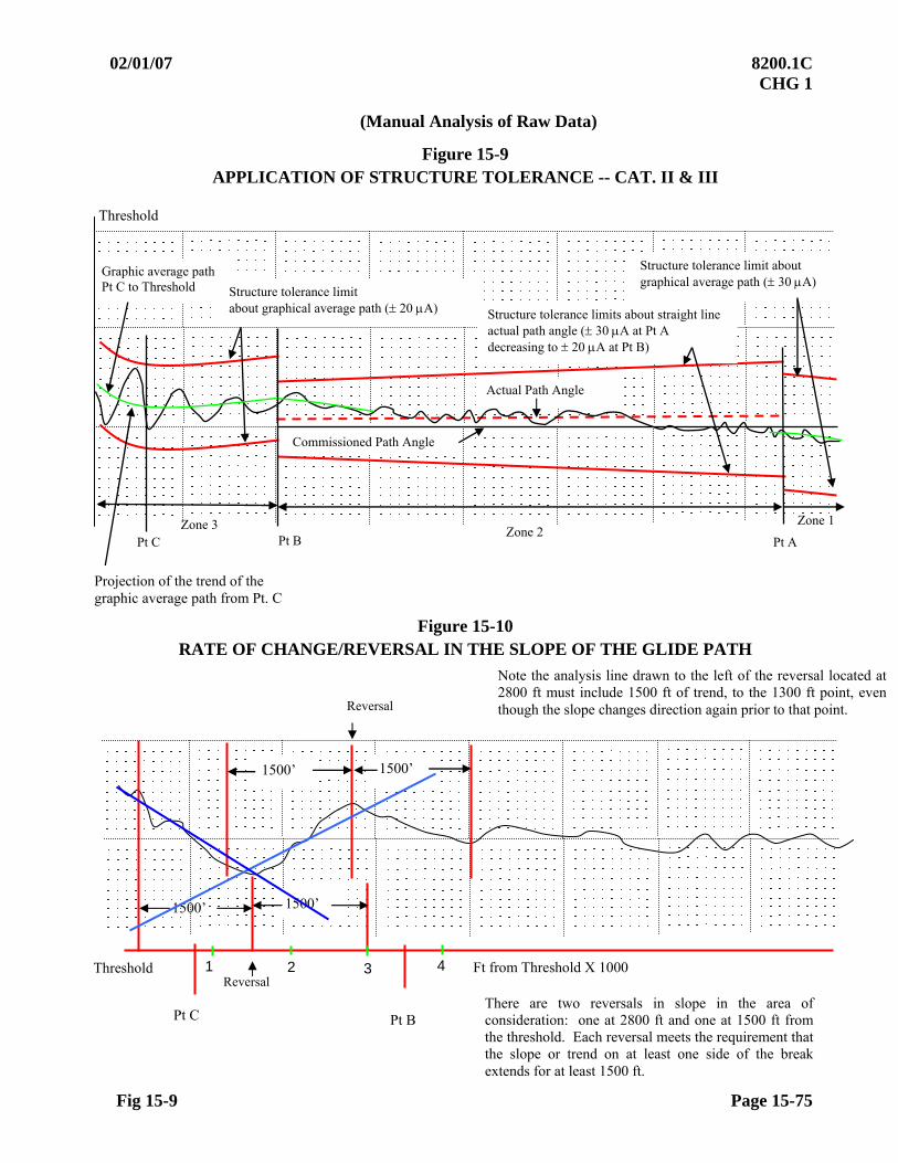
02/01/07 8200.1C CHG 1
Fig 15-9 Page 15-75
(Manual Analysis of Raw Data)
Figure 15-9 APPLICATION OF STRUCTURE TOLERANCE -- CAT. II & III
Figure 15-10 RATE OF CHANGE/REVERSAL IN THE SLOPE OF THE GLIDE PATH
Threshold
Projection of the trend of the graphic average path from Pt. C
Graphic average path Pt C to Threshold Structure tolerance limit
about graphical average path ( 20 A)
Commissioned Path Angle
Actual Path Angle
Structure tolerance limits about straight line actual path angle ( 30 A at Pt A decreasing to 20 A at Pt B)
Structure tolerance limit about graphical average path ( 30 A)
Zone 1 Zone 2
Pt A Pt B Pt C Zone 3
1500’ 1500’
1500’ 1500’
Reversal Threshold
Pt B
1 2 3 4
There are two reversals in slope in the area of consideration: one at 2800 ft and one at 1500 ft from the threshold. Each reversal meets the requirement that the slope or trend on at least one side of the break extends for at least 1500 ft.
Ft from Threshold X 1000
Pt C
Reversal
Note the analysis line drawn to the left of the reversal located at 2800 ft must include 1500 ft of trend, to the 1300 ft point, even though the slope changes direction again prior to that point.
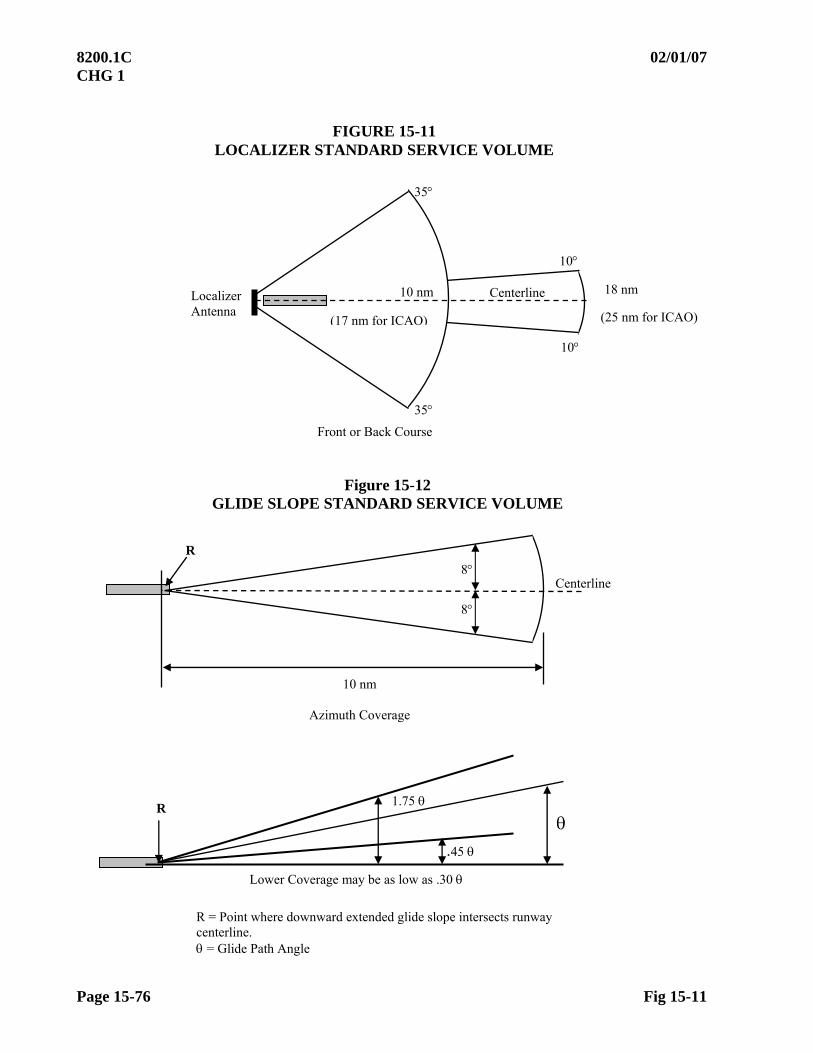
8200.1C 02/01/07 CHG 1
Page 15-76 Fig 15-11
FIGURE 15-11 LOCALIZER STANDARD SERVICE VOLUME
Localizer Antenna
Front or Back Course
35
35
10 nm 18 nm
10
10
Centerline
Figure 15-12 GLIDE SLOPE STANDARD SERVICE VOLUME
R
10 nm
Azimuth Coverage
8
8
Centerline
.45
1.75 R
Lower Coverage may be as low as .30
R = Point where downward extended glide slope intersects runway centerline. = Glide Path Angle
(17 nm for ICAO) (25 nm for ICAO)

02/01/07 8200.1C CHG 1
Par 15.60 Page 15-77
SECTION 6. TOLERANCES 15.60 TOLERANCES
CODES:
C Tolerances that are applied to site, commissioning, reconfiguration, and categorization inspection.
P Tolerances that are applied to any inspection subsequent to the inspections outlined in Code C.
a. Localizers
INSPECTION PARAMETER
REFERENCE PARAGRAPH C P
TOLERANCE/ LIMIT
Spectrum Analysis Reserved
Modulation Level
Waveguide Clearance XMTR
15.20b X
X
X
X
36 – 44% as measured IAW Paragraph 15.20b
30% - 60% throughout the service volume of all localizers installed or reconfigured with new type antennas after 01/01/2000. For existing systems, note in the flight inspection report areas where modulation exceeds 60%.
For two-frequency systems, the standard for maximum modulation percentage does not apply at or near azimuth where the course and clearance signal levels are equal in amplitude (i.e., at azimuths where both transmitting systems have a significant contribution to the total modulation percentage). 36 – 44% as measured IAW Paragraph 15.20b
Power Ratio 15.20d X The course transmitter power level must be at least 10 dB greater than the clearance transmitter.
Phasing 15.20e As Required No tolerance.
Width
15.20f Maximum6.0 (SDF-12.0). CAT II & III tailored to 700 ft. Precision approach400 ft minimum course width at the threshold.
Front Course X 0.1 of the commissioned width.
X Within 17% of the commissioned width.
Transmitter Differential (Front Course)
X The difference in the normal widths must not be greater than 0.5 or 10% of the commissioned width, whichever is least.
Back Course X Between 3.0 and 6.0 X Between 2.49 and 7.02 in normal or monitor alarm condition. X X SDFs Within 10% of the front course sector width.
Symmetry (Front Course Only)
15.20f X X With the facility in normal: 45-55%.

8200.1C 9/14/09 Chg 2
Page 15-78 Par 15.60a
PARAMETER REFERENCE PARAGRAPH
INSPECTION TOLERANCE/LIMIT
C P
Alignment 15.20g
Front Course and Independently Monitored Back Courses
X
X
Within 3 A of the designed procedural azimuth.
For ILS(s), localizer-only on centerline and SDF(s) on centerline. From the designed procedural azimuth: CAT I 15 A. CAT II 11 A. CAT III 9 A. Offset Localizers, Offset SDF(s), and LDA(s) 20A Back Course 20 A.
At the conclusion of a monitor inspection or when alignment is adjusted, FAA, non-Federal civil, U.S. Army, and U.S. Navy/ Marine Corps localizers must be ≤ 3A, LDA(s), offset localizers must be ≤ 8A, and independently monitored back courses must be ≤ 10A.
Back Course (Facilities subordinate to front course.)
X X Designed procedural azimuth 65 A.
Course Structure 15.20g
Front Course X X Zone 1From the graphical average course: CAT I, II, III 30 A to Point A SDF: 40 A to Point A
NOTE: For localizer only approaches (ILS facilities), including RF alarm, and when alignment is determined as S/ U, structure may be measured from graphical average course
Zone 2From the actual course alignment: CAT I: 30 A at Point A; linear decrease to 15A at Point B. CAT II, III: 30 A at Point A; linear decrease to 5A at Point B, SDF: 40 A at Point A; linear decrease to 20A at Point B. Zone 3From the actual course alignment: CAT I: 15 A at Point B; 15A at Point C. SDF: 20 A at Point C.
Zones 3 & 4From the actual course alignment. CAT II, III: 5 A at Point B; 5 A to Point D. Zone 5From the actual course alignment. CAT III: 5 A at Point D; linear increase to 10 A at Point E.
Back Course
X X Zone 1From the graphical average course: 40 A to Point A. Zone 2From actual course alignment: 40 A at Point A; linear decrease to 20 A at Point B. Zone 3From actual course alignment 20 A at Point B; 20 A at Point C.
Front and Back Course 15.50a X X Exception: An aggregate out-of-tolerance condition for 354 ft may be acceptable in a 7,089-foot segment.
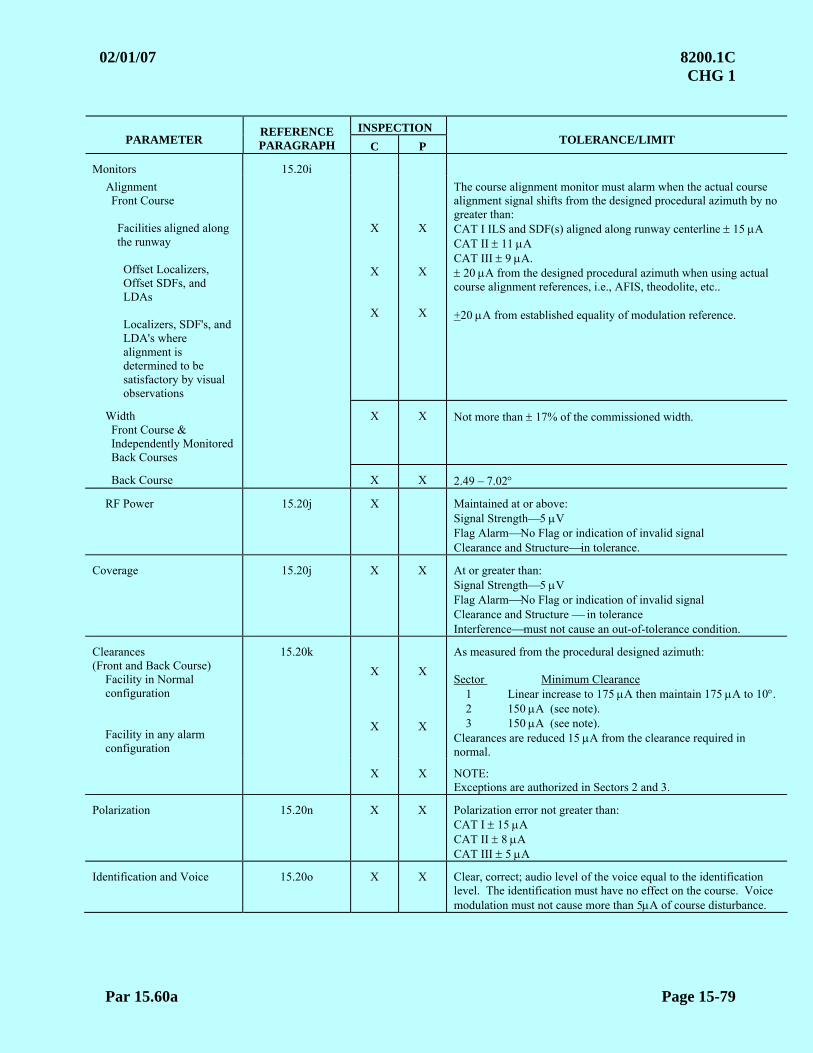
02/01/07 8200.1C CHG 1
Par 15.60a Page 15-79
INSPECTION PARAMETER
REFERENCE PARAGRAPH C P
TOLERANCE/LIMIT
Monitors 15.20i
Alignment Front Course
Facilities aligned along the runway
Offset Localizers, Offset SDFs, and LDAs Localizers, SDF's, and LDA's where alignment is determined to be satisfactory by visual observations
X
X
X
X
X
X
The course alignment monitor must alarm when the actual course alignment signal shifts from the designed procedural azimuth by no greater than: CAT I ILS and SDF(s) aligned along runway centerline 15 A CAT II 11 A CAT III 9 A. 20 A from the designed procedural azimuth when using actual course alignment references, i.e., AFIS, theodolite, etc.. +20 A from established equality of modulation reference.
Width Front Course & Independently Monitored Back Courses
X X
Not more than 17% of the commissioned width.
Back Course X X 2.49 – 7.02
RF Power 15.20j X Maintained at or above: Signal Strength5 V Flag AlarmNo Flag or indication of invalid signal Clearance and Structurein tolerance.
Coverage 15.20j X X At or greater than: Signal Strength5 V Flag AlarmNo Flag or indication of invalid signal Clearance and Structure in tolerance Interferencemust not cause an out-of-tolerance condition.
Clearances (Front and Back Course)
Facility in Normal configuration
Facility in any alarm configuration
15.20k
X
X
X
X
As measured from the procedural designed azimuth: Sector Minimum Clearance 1 Linear increase to 175 A then maintain 175 A to 10. 2 150 A (see note). 3 150 A (see note). Clearances are reduced 15 A from the clearance required in normal.
X X NOTE:
Exceptions are authorized in Sectors 2 and 3.
Polarization 15.20n X X Polarization error not greater than: CAT I 15 A CAT II 8 A CAT III 5 A
Identification and Voice 15.20o X X Clear, correct; audio level of the voice equal to the identification level. The identification must have no effect on the course. Voice modulation must not cause more than 5A of course disturbance.
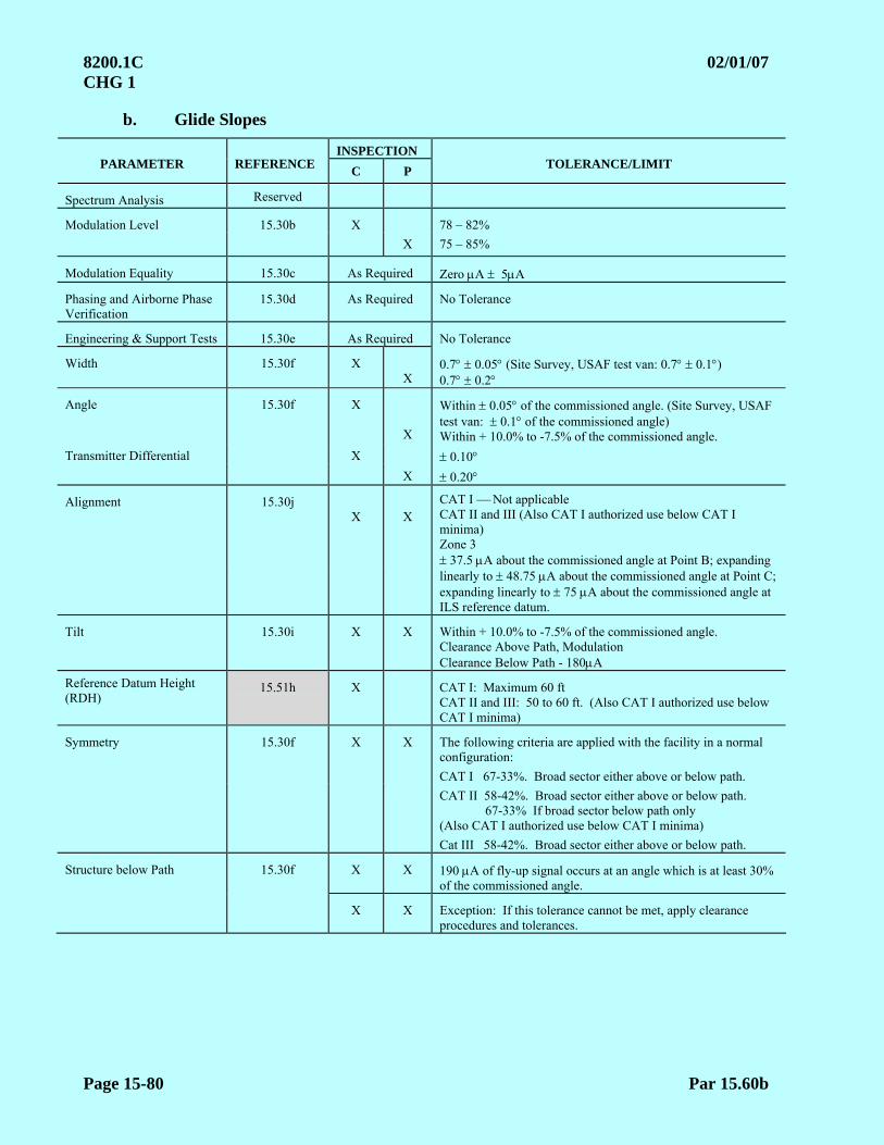
8200.1C 02/01/07 CHG 1
Page 15-80 Par 15.60b
b. Glide Slopes
INSPECTION PARAMETER REFERENCE
C P TOLERANCE/LIMIT
Spectrum Analysis Reserved
Modulation Level 15.30b X 78 – 82%
X 75 – 85%
Modulation Equality 15.30c As Required Zero A 5A
Phasing and Airborne Phase Verification
15.30d As Required No Tolerance
Engineering & Support Tests 15.30e As Required No Tolerance
Width 15.30f X
X
0.7 0.05 (Site Survey, USAF test van: 0.7 0.1) 0.7 0.2
Angle
15.30f
X
X
Within 0.05 of the commissioned angle. (Site Survey, USAF test van: 0.1 of the commissioned angle) Within + 10.0% to -7.5% of the commissioned angle.
Transmitter Differential X 0.10 X 0.20
Alignment 15.30j X
X
CAT I Not applicable CAT II and III (Also CAT I authorized use below CAT I minima) Zone 3 37.5 A about the commissioned angle at Point B; expanding
linearly to 48.75 A about the commissioned angle at Point C; expanding linearly to 75 A about the commissioned angle at ILS reference datum.
Tilt 15.30i X X Within + 10.0% to -7.5% of the commissioned angle. Clearance Above Path, Modulation Clearance Below Path - 180A
Reference Datum Height (RDH)
15.51h X CAT I: Maximum 60 ft CAT II and III: 50 to 60 ft. (Also CAT I authorized use below CAT I minima)
Symmetry 15.30f X X The following criteria are applied with the facility in a normal configuration:
CAT I 67-33%. Broad sector either above or below path. CAT II 58-42%. Broad sector either above or below path.
67-33% If broad sector below path only (Also CAT I authorized use below CAT I minima)
Cat III 58-42%. Broad sector either above or below path.
Structure below Path 15.30f X X 190 A of fly-up signal occurs at an angle which is at least 30% of the commissioned angle.
X X Exception: If this tolerance cannot be met, apply clearance procedures and tolerances.
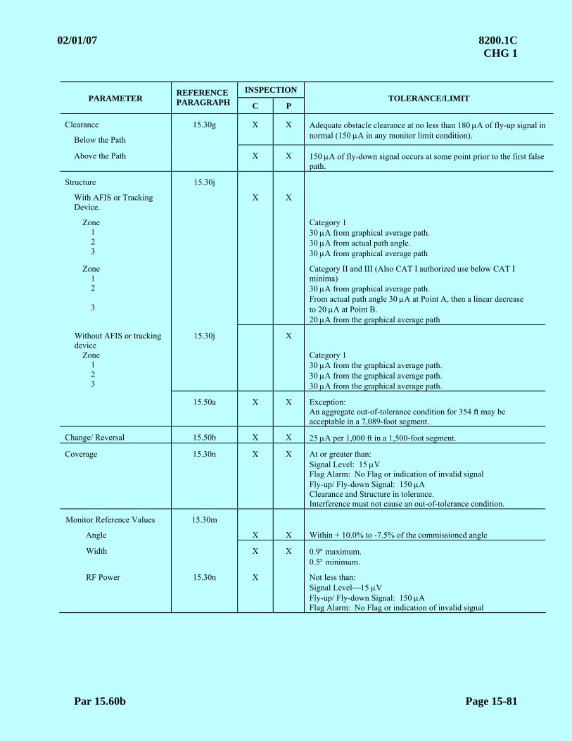
02/01/07 8200.1C CHG 1
Par 15.60b Page 15-81
INSPECTION PARAMETER
REFERENCE PARAGRAPH C P
TOLERANCE/LIMIT
Clearance
Below the Path
15.30g X X Adequate obstacle clearance at no less than 180 A of fly-up signal in normal (150 A in any monitor limit condition).
Above the Path X X 150 A of fly-down signal occurs at some point prior to the first false path.
Structure 15.30j
With AFIS or Tracking Device.
X X
Zone 1 2 3
Category 1 30 A from graphical average path. 30 A from actual path angle. 30 A from graphical average path
Zone 1 2 3
Category II and III (Also CAT I authorized use below CAT I minima) 30 A from graphical average path. From actual path angle 30 A at Point A, then a linear decrease to 20 A at Point B. 20 A from the graphical average path
Without AFIS or tracking device
Zone 1 2 3
15.30j
X
Category 1 30 A from the graphical average path. 30 A from the graphical average path. 30 A from the graphical average path.
15.50a X X Exception: An aggregate out-of-tolerance condition for 354 ft may be acceptable in a 7,089-foot segment.
Change/ Reversal 15.50b X X 25 A per 1,000 ft in a 1,500-foot segment.
Coverage 15.30n X X At or greater than: Signal Level: 15 V Flag Alarm: No Flag or indication of invalid signal Fly-up/ Fly-down Signal: 150 A Clearance and Structure in tolerance. Interference must not cause an out-of-tolerance condition.
Monitor Reference Values 15.30m
Angle
X X Within + 10.0% to -7.5% of the commissioned angle
Width X X 0.9 maximum. 0.5 minimum.
RF Power 15.30n X Not less than: Signal Level15 V Fly-up/ Fly-down Signal: 150 A Flag Alarm: No Flag or indication of invalid signal

8200.1C 02/01/07 CHG 1
Page 15-82 Par 15.60c
c. 75 MHz Marker Tolerances. Marker beacons must meet these tolerances or be removed from service. The following tolerances are applied with the receiver sensitivity in low.
Parameter Reference Paragraph
Tolerance/Limit
Electromagnetic Spectrum Reserved Interference must not cause an out-of-tolerance condition.
Identification 15.40b Distinct, correct, constant throughout the coverage area; and clearly distinguishable from any other markers.
Modulation 15.40b The modulation must illuminate the following lights: OM - Blue Light (400 Hz)
MM - Amber Light (1,300 Hz) IM - White Light (3,000 Hz) FM - White Light (3,000 Hz)
Coverage 15.40c With a constant signal at or above 1,700 microvolts (V), the following widths must be provided:
Minor Axis 15.40c(1) ILS Outer Marker
Width must not be less than 1,350 ft or more than 4,000 ft
ILS Middle Marker Width must not be less than 675 ft or more than 1,325 ft ILS Inner Marker Width must not be less than 340 ft or more than 660 ft Fan Markers Used for a missed approach Width must not be less than 1,000 ft or more than 3,000 ft or step-down fix in the final approach segment All others Same as ILS Outer Marker
Major Axis
15.40c(2)
ILS Outer Marker * Minimum: 700 ft Maximum: 4,000 ft Those markers installed to serve dual runways must not exceed 4,000 ft within the normal localizer width sector of 150 A, either side of the procedural centerline.
ILS Middle Marker * Minimum: 350 ft Maximum: 1,325 ft
ILS Inner Marker * Not Applicable
All Others * Any duration not to exceed the respective minor axis tolerance.
Separation A separation between the 1,700 V points of succeeding marker patterns which provide a fix on the same approach course; e.g., MM to IM, must be at least 709 ft.
* As measured along the minor axis at the extremities of the pre-defined off-course sector.
15.61 ADJUSTMENTS. See Chapter 4, Section 3. When equipment performance characteristics are abnormal but within tolerances, they should be discussed with maintenance personnel to determine if adjustments will increase the overall performance of the systems. Following any adjustment to correct an out-of-tolerance condition, the appropriate monitor(s) must be checked and proper monitor operation verified.
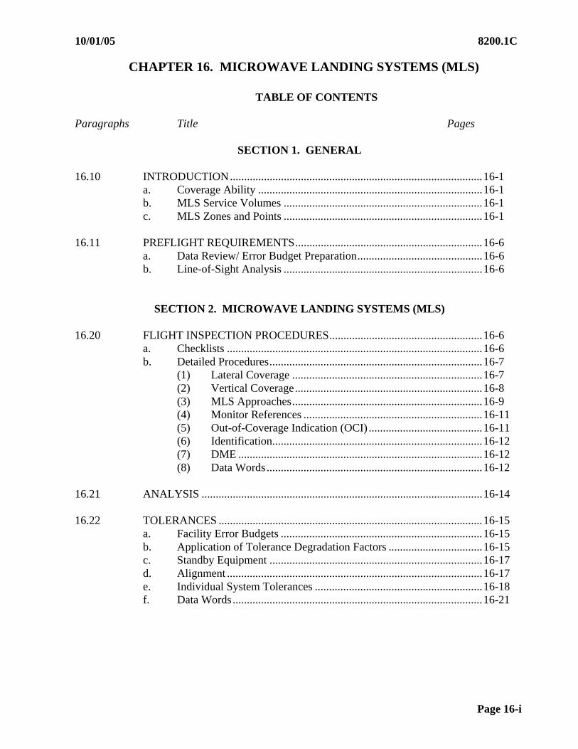
10/01/05 8200.1C
Page 16-i
CHAPTER 16. MICROWAVE LANDING SYSTEMS (MLS)
TABLE OF CONTENTS
Paragraphs Title Pages
SECTION 1. GENERAL 16.10 INTRODUCTION.........................................................................................16-1
a. Coverage Ability ...............................................................................16-1 b. MLS Service Volumes ......................................................................16-1 c. MLS Zones and Points ......................................................................16-1
16.11 PREFLIGHT REQUIREMENTS..................................................................16-6
a. Data Review/ Error Budget Preparation............................................16-6 b. Line-of-Sight Analysis ......................................................................16-6
SECTION 2. MICROWAVE LANDING SYSTEMS (MLS) 16.20 FLIGHT INSPECTION PROCEDURES......................................................16-6
a. Checklists ..........................................................................................16-6 b. Detailed Procedures...........................................................................16-7
(1) Lateral Coverage ...................................................................16-7 (2) Vertical Coverage..................................................................16-8 (3) MLS Approaches...................................................................16-9 (4) Monitor References ...............................................................16-11 (5) Out-of-Coverage Indication (OCI) ........................................16-11 (6) Identification..........................................................................16-12 (7) DME ......................................................................................16-12 (8) Data Words............................................................................16-12
16.21 ANALYSIS ...................................................................................................16-14 16.22 TOLERANCES .............................................................................................16-15
a. Facility Error Budgets .......................................................................16-15 b. Application of Tolerance Degradation Factors .................................16-15 c. Standby Equipment ...........................................................................16-17 d. Alignment ..........................................................................................16-17 e. Individual System Tolerances ...........................................................16-18 f. Data Words........................................................................................16-21
8200.1C 10/01/05
Page 16-ii
TABLE OF CONTENTS
Paragraphs Title Pages
FIGURES Figure 16-1 Approach Azimuth/ Data Coverage - Horizontal and Vertical ............. 16-2 Figure 16-2 Approach Elevation Coverage – Horizontal and Vertical ..................... 16-3 Figure 16-3 MLS Points and Zones - Standard MLS................................................ 16-4 Figure 16-4 MLS Points and Zones - Offset MLS.................................................... 16-4 Figure 16-5 MLS Points and Zones - Collocated MLS............................................. 16-5 Figure 16-6 MLS Points and Zones - Point in Space MLS....................................... 16-5
TABLES Table 16-1 MLS Reference Arc Altitudes ............................................................... 16-8 Table 16-2 MLS Data Word Translator ................................................................. 16-12 Table 16-3 Tolerance Degradatio Computation..................................................... 16-17
SECTION 3. MOBILE MICROWAVE LANDING SYSTEM (MMLS) 16.30 INTRODUCTION ........................................................................................... 16-22 16.31 CHECKLIST ................................................................................................... 16-23 16.32 DETAILED PROCEDURES........................................................................... 16-24
Detailed Procedures for Collocated MMLS Providing Computer Centerline Approach....................................................................... 16-24 a. Coverage Arcs ..................................................................................... 16-25 b. Vertical Coverage ................................................................................ 16-25 c. Computed Centerline Approaches....................................................... 16-25 d. Monitors............................................................................................... 16-26 e. MMLS Data Words ............................................................................. 16-26
Data Word Translator .......................................................................... 16-26 f. ID ......................................................................................................... 16-28 g. DME .................................................................................................... 16-28
16.33 ANALYSIS...................................................................................................... 16-28
10/01/05 8200.1C
Page 16-iii (and iv)
TABLE OF CONTENTS
Paragraphs Title Pages 16.34 TOLERANCES ................................................................................................16-29
a. Facility Error Budgets ..........................................................................16-29 b. Application of Tolerance Degradation Factors ....................................16-30 c. Standby Equipment ..............................................................................16-31 d. Alignment .............................................................................................16-32 e. Individual System Tolerances ..............................................................16-32 f. Data Words...........................................................................................16-33
FIGURES
Figure 16-7 Pseudo Runway .............................................................................................16-34 Figure 16-8 Azimuths for Coverage Below Path (Computed Centerline Facilities..........16-35 Figure 16-9 MMLS Coverage Validation and Minimum Proportional Guidance ............16-36
TABLES Table 16-4 MMLS Reference Arc Altitudes ...................................................................16-24 Table 16-5 MMLS Data Word Translator .......................................................................16-26 Table 16-6 Tolerance Degradation Computation ............................................................16-31

This Page Intentionally Left Blank
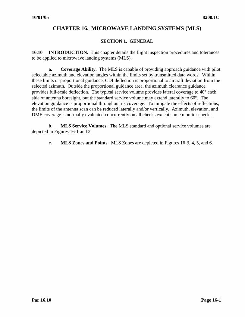
10/01/05 8200.1C
Par 16.10 Page 16-1
CHAPTER 16. MICROWAVE LANDING SYSTEMS (MLS)
SECTION 1. GENERAL 16.10 INTRODUCTION. This chapter details the flight inspection procedures and tolerances to be applied to microwave landing systems (MLS).
a. Coverage Ability. The MLS is capable of providing approach guidance with pilot selectable azimuth and elevation angles within the limits set by transmitted data words. Within these limits or proportional guidance, CDI deflection is proportional to aircraft deviation from the selected azimuth. Outside the proportional guidance area, the azimuth clearance guidance provides full-scale deflection. The typical service volume provides lateral coverage to 40 each side of antenna boresight, but the standard service volume may extend laterally to 60. The elevation guidance is proportional throughout its coverage. To mitigate the effects of reflections, the limits of the antenna scan can be reduced laterally and/or vertically. Azimuth, elevation, and DME coverage is normally evaluated concurrently on all checks except some monitor checks.
b. MLS Service Volumes. The MLS standard and optional service volumes are depicted in Figures 16-1 and 2.
c. MLS Zones and Points. MLS Zones are depicted in Figures 16-3, 4, 5, and 6.
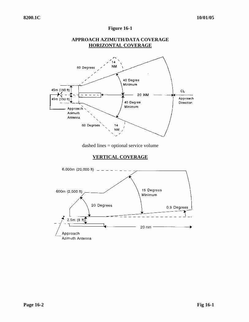
8200.1C 10/01/05
Page 16-2 Fig 16-1
Figure 16-1
APPROACH AZIMUTH/DATA COVERAGE HORIZONTAL COVERAGE
dashed lines = optional service volume
VERTICAL COVERAGE
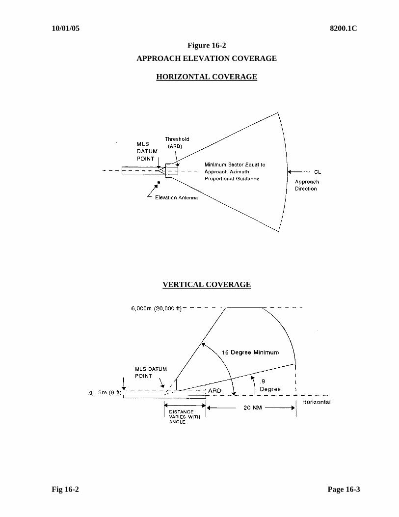
10/01/05 8200.1C
Fig 16-2 Page 16-3
Figure 16-2
APPROACH ELEVATION COVERAGE
HORIZONTAL COVERAGE
VERTICAL COVERAGE

8200.1C 10/01/05
Page 16-4 Fig 16-3
MLS POINTS AND ZONES
Figure 16-3
STANDARD MLS
Figure 16-4
OFFSET MLS
20 nm or ESV
4nm
3500 ft
Zone 1
Zone 2
Zone 3
Zone 4
Zone 5
3000 ft
2000 ft
Azimuth Site
EL
Point A
Point B
Point D
Point E
ARD
Zone 3 is variable based on MAP
Point B
20nm
4 nm
3500 ft
Zone 2
* MAP
Point A
Elevation site
Azimuth site
CL
Zone 1
*MAP is variable based on decision altitude

10/01/05 8200.1C
Fig 16-5 Page 16-5
MLS POINTS AND ZONES, CONTINUED
Figure 16-5
COLLOCATED MLS
Figure 16-6
POINT IN SPACE MLS
20 nm or ESV
4nm
3500 ft
Zone 1
Zone 2
Zone 3 Variable based on MAP
AZ EL
Point A
Point B
ARD
*MAP
* MAP variable based on decision altitude
Aligned to support a precision
approach (special avionics required
to compute centerline
approaches).
20 nm or ESV
4nm
3500 ft
Zone 1
Zone 2
Zone 3 Variable based on MAP
AZ EL
Point A
Point B
ARD
*MAP
* MAP Variable based on decision altitude
Not aligned to support a
precision approach
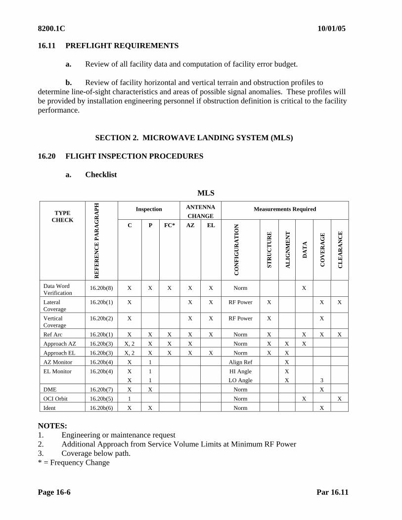
8200.1C 10/01/05
Page 16-6 Par 16.11
16.11 PREFLIGHT REQUIREMENTS
a. Review of all facility data and computation of facility error budget. b. Review of facility horizontal and vertical terrain and obstruction profiles to
determine line-of-sight characteristics and areas of possible signal anomalies. These profiles will be provided by installation engineering personnel if obstruction definition is critical to the facility performance.
SECTION 2. MICROWAVE LANDING SYSTEM (MLS) 16.20 FLIGHT INSPECTION PROCEDURES
a. Checklist
MLS
Inspection ANTENNA
CHANGE Measurements Required
TYPE CHECK
RE
FE
RE
NC
E P
AR
AG
RA
PH
C P FC* AZ EL
CO
NF
IGU
RA
TIO
N
ST
RU
CT
UR
E
AL
IGN
ME
NT
DA
TA
CO
VE
RA
GE
CL
EA
RA
NC
E
Data Word Verification
16.20b(8) X X X X X Norm X
Lateral Coverage
16.20b(1) X X X RF Power X X X
Vertical Coverage
16.20b(2) X X X RF Power X X
Ref Arc 16.20b(1) X X X X X Norm X X X X
Approach AZ 16.20b(3) X, 2 X X X Norm X X X
Approach EL 16.20b(3) X, 2 X X X X Norm X X
AZ Monitor 16.20b(4) X 1 Align Ref X
EL Monitor 16.20b(4) X 1 HI Angle X
X 1 LO Angle X 3
DME 16.20b(7) X X Norm X
OCI Orbit 16.20b(5) 1 Norm X X
Ident 16.20b(6) X X Norm X
NOTES: 1. Engineering or maintenance request 2. Additional Approach from Service Volume Limits at Minimum RF Power 3. Coverage below path. * = Frequency Change

10/01/05 8200.1C
Par 16.20b Page 16-7
b. Detailed Procedures
(1) Lateral Coverage. Coverage arcs are used to define and certify the lateral and distance limits of AZ, EL, and DME coverage. Evaluate proportional guidance and clearance coverage.
(a) Service Volume Arc. A commissioning inspection maneuver to define and certify the operational range, lateral, and vertical limits of the MLS service volume. Perform the inspection with the facility operating at the lowest computed power required to establish adequate signal coverage for the intended service volume.
1 Positioning. Start the arc at the maximum usable distance and 5 outside the edge of the service volume limit. Maintain an altitude equal to the minimum glide path (MGP). If signal coverage of all MLS components cannot be maintained at the MGP, the MLS must be restricted. There is no requirement to certify the lower, 0.9, or higher, 20,000 ft, limits of lateral coverage unless procedurally or operationally required. The Optional Service Volume Arc should be flown at a distance of 14 nm.
2 Inspection
a There must be no less than 10 proportional guidance
either side of the procedural on course.
b While traversing the azimuth proportional guidance sectors, record azimuth and elevation deviation. Deviation crosspointer fluctuations greater than 0.5 that exceed 2 of arc, and all MLS receiver unlocks, must be validated by radial flight, using the procedures outlined in Paragraph 16.20b(2) (Vertical Coverage).
(b) Reference Arc: A commissioning and periodic arc throughout the
proportional guidance area to assure azimuth and elevation signal coverage at the lower edge of elevation deflection sensitivity.
1 Positioning. At a distance of between 5 and 10 nm from the
ARD, start the arc 5 outside the edge of the service volume. Vertical altitude must be computed to equal the MGP x 0.75 at the distance flown. The distance and altitude at which the arc is flown on commissioning will be recorded on the Facility Data Sheet. This must be the reference for periodic evaluations.
2 Altitudes. The approximate (including earth curvature) arc
altitudes above site elevation are computed below for selected angles and distance. Maintaining a centered elevation crosspointer at the correct distance will give a more precise altitude and is the preferred method of flying the arcs. See Table 16-1 for reference arc altitudes.

8200.1C 10/01/05
Page 16-8 Par 16.20b
Table 16-1 MLS REFERENCE ARC ALTITUDES
MGP
ANGLE MGP
@ 20 nm
MGP x 0.75
@ 5 nm
MGP x 0.75
@ 6 nm
MGP x 0.75
@ 7 nm
MGP x 0.75
@ 8 nm
MGP x 0.75
@ 9 nm
MGP x 0.75
@ 10 nm
2.5 5659 1017 1225 1436 1648 1862 2077
2.6 5871 1056 1273 1491 1711 1933 2157
2.7 6084 1096 1321 1547 1775 2005 2237
2.8 6297 1136 1369 1603 1839 2077 2316
2.9 6509 1176 1416 1659 1903 2148 2396
3 6722 1216 1464 1714 1966 2220 2476
3.1 6935 1256 1512 1770 2030 2292 2555
3.2 7147 1295 1560 1826 2094 2363 2635
3.3 7360 1335 1608 1882 2158 2435 2715
3.4 7573 1375 1655 1937 2250 2507 2794
3.5 7786 1415 1703 1993 2285 2579 2874
4 8851 1614 1942 2272 2604 2937 3273
4.5 9917 1814 2182 2552 2923 3296 3672
5 10985 2013 2421 2831 3243 3656 4071
5.5 12054 2213 2661 3111 3562 4015 4470
6 13126 2413 2901 3391 3882 4375 4870
3 Inspection
a There must be no less than 10 proportional guidance either side of the procedural on course.
b While traversing the proportional guidance sectors,
record azimuth and elevation deviation. Deviation crosspointer fluctuations greater than 0.5 that exceed 2 of arc, and all MLS receiver unlocks, must be validated by radial flight using the procedures outlined in Paragraph 16.20b(2) (Vertical Coverage).
(2) Vertical Coverage
(a) Purpose
1 A commissioning maneuver to evaluate vertical coverage of
the azimuth and elevation on the procedural azimuth and at + 10 each side.
2 Validate elevation and azimuth deviation crosspointer fluctuations noted on arcs.
02/01/07 8200.1C CHG 1
Par 16.20b(2) Page 16-9
(b) Positioning. Accomplish this check by performing a level run at an altitude equal to MGP x 0.75 as calculated at the FAF distance, starting at the standard service volume. While flying inbound, determine the angle at which a consistent satisfactory signal is achieved. If this angle is higher than 0.9, the facility must be restricted. If the angle found is greater than MGP x 0.75, the facility is unusable.
(c) Inspection. Record deviation, PFN, and CMN. Observe the
azimuth and elevation crosspointers for excessive signal aberrations which may indicate multipath or signal shadowing. Observe the elevation crosspointer for a smooth linear transition terminating between 15 and 20.
1 When fluctuations exceed 0.5 within 10 of the
procedural on course, fly the approach offset 5 on the affected side(s) of the procedural on course and apply PFN and CMN tolerances. If the 5 offset approach is satisfactory, the approach may be placed in service.
2 Validation of deviations noted on arcs must be discussed
with maintenance personnel for corrective action. If not correctable, the area in question must be restricted.
3 Increases in the minimum EL lower scan limit may present
an erroneous crosspointer indication at elevation angles below the scan limit. The elevation coverage should be restricted below the adjusted lower scan limit.
4 Increases in the minimum EL lower scan limit made after
determination of normal path structure requires a recheck of the EL approach guidance inside the FAF.
(3) MLS Approaches
(a) Purpose. The approach should be the first maneuver flown during a
commissioning, reconfiguration, or restoration flight inspection, so that the azimuth and elevation course and coverage may be optimized to the desired procedural alignment. This maneuver is performed to verify that the azimuth and elevation facilities will satisfactorily support the proposed or published approach and categories of intended use.
(b) Positioning. Approaches must be evaluated on the designed
procedural azimuth and the minimum glidepath, unless otherwise indicated. For the purpose of evaluating structure, optimizing azimuth and elevation alignments, and conducting periodic inspections, start the approach at a distance not closer than the published FAF, GSI, or 6 miles from runway threshold, whichever is greater. For commissioning, fly the approach on the MGP from the desired service volume limits at normal power and while the facility is at minimum RF power.

8200.1C 10/01/05
Page 16-10 Par 16.20b(3)
(c) MLS Approaches Which Support Azimuth Only Minima. The final approach segment of azimuth only minima must be checked during site evaluation, commissioning, and special inspections for azimuth antenna change and anytime there is significant deterioriation of azimuth structure. Upon reaching the FAF inbound, descend at a rate of approximately 400 ft per mile (930 ft per minute at 140 knots; 800 ft per minute at 120 knots) to an altitude of 100 ft below the lowest published MDA and maintain this altitude to the MAP.
(d) Inspection
1 Azimuth facilities sited along runway centerline with Decision Altitudes of 200 ft or less must be evaluated through Zones 1, 2, and 3 (also Zones 4 and 5 if autoland or CAT II/ III operations are authorized) on all inspections requiring alignment and structure measurements; elevation guidance on these facilities must be evaluated to the ARD. All other facilities must be evaluated to 100 ft below Decision Altitude (DA).
NOTE: During site, commissioning, reconfiguration, categorization, antenna, and/or frequency change inspection—check all of Zone 1.
All other inspections (i.e., periodic, periodic with monitors, etc.) evaluate structure from published FAF, GSI,or 6 nm (whichever is further) through all other required zones.
2 Approved RTT and/or AFIS methods must be used for the
approach evaluation. The facility error budget will provide all tolerances to be used during commissioning and periodic flight inspection. Mean course error (MCE) must be established prior to application of PFE tolerances. Exclude data in areas that are restricted due to facility performance.
3 For azimuth facilities sited along runway centerline IAW Figure 16-3, with a Decision Altitude at or below 200 ft, the azimuth MCE must be determined and reported as found in the 1.0 nm segment ending at the ARD. For other facilities, use the 1.0 nm segment, ending at 100 ft below DA. For elevation facilities, determine the glide angle in Zone 2 as defined in Figures 16-3, 4, and 5.
4 Visual Autoland or Category II or III Operations Authorized.
On commissioning inspections, cross Point C at 100 ft, runway threshold at approximately 50 ft, and continue on the extended glidepath angle to the touchdown point. Continue the landing roll and determine the actual course alignment for Zones 4 and 5. Measure the course structure from the actual alignment. If the actual alignment for Zones 4 and 5 cannot be determined using this method, taxi the aircraft along the runway centerline from abeam the elevation site to Point E. Record the raw crosspointer information and mark, abeam the elevation site, Point D and Point E. Manually calculate the actual course alignment and structure for each of the required zones.
10/01/05 8200.1C
Par 16.20b(4) Page 16-11
(4) Monitor References
(a) Purpose: To provide Facilities Maintenance personnel reference readings to be used in the validation of facility monitoring parameters. Facility discrepancies must be assigned if the alignment shift results in out-of-tolerance PFE at any distance on the approach.
(b) Inspection
1 Azimuth monitor references must be established after the facility is optimized to a MCE within 0.02 of the designed procedural azimuth. After the MCE is established, have maintenance personnel shift the system to one side, record the reference, shift the same amount to the other side, record the reference, then restore to normal. Azimuth monitors can also be established on the ground when parked within proportional guidance, maintaining line-of-sight at the maximum practical distance from the antenna. When azimuth monitors are checked on the ground, algebraically add the azimuth shift to the reported maximum PFE on the approach.
2 Elevation monitor references are established airborne and require the MGP to be established within 0.02 of the commissioned angle prior to accomplishment. Request an elevation angle change of no greater than 0.10 high, record the reference, have the elevation angle changed to no greater than 0.10 low, record the reference, then restore to normal.
3 If the elevation lower scan angle limit is increased to improve PFE, recheck normal EL path structure.
(c) Below Path Coverage Evaluation. Perform this check during a commissioning flight inspection when in low angle alarm. Three runs are required, one on procedural centerline, and at 2 either side of centerline. With the MGP selected for evaluation, fly at an angle equal to [(MGP x 0.75) - 0.25]. Ensure a full-scale fly up indication is maintained on the elevation signal and AZ guidance and obstacle clearance can be maintained from the FAF to the MAP.
(5) Out-of-Coverage Indication (OCI). The purpose of the OCI check is to ensure that no false angle decoding occurs outside of proportional guidance coverage areas. This check is accomplished at maintenance request if there are procedural requirements beyond the service volume. Fly an orbit radius of 6 to 10 miles about the azimuth facility for this check. The aircraft will be flown at an altitude as close to the MGP that line of site with the MLS facilities will allow. During the orbit, note the position of any decoded angles lasting longer than 4 seconds or 1.5 of arc, whichever is greater. Return to the area after completing the orbit and manually program the decoded angle into the receiver. If the angle can be locked onto and flown as a radial, even though an OCI signal is present, the problem must be corrected, or the facility restricted. MMLS does not have OCI capability.

8200.1C 10/01/05
Page 16-12 Par 16.20b(6)
(6) Identification. The purpose of the identification check is to ensure correct identification is received throughout the coverage area. Validate the identification by listening to the Morse code or recording Basic Data Word 6.
(7) DME. The DME must be evaluated as a DME/ N throughout all areas of coverage. MLS DME is specified by ICAO to transmit the three-letter ID, dropping the preceeding M. Evaluate DME accuracy IAW Chapter 11. Currently commissioned facilities transmitting 4-letter on DME (e.g., M-XXX) function must be left in service.
(8) Data Words. The receiver uses transmitted data words containing facility siting and approach information to process AZ and EL angle information, identify the station, and determine crosspointer sensitivity. Basic data words are used for all approaches. Auxiliary data words are used for RNAV or Computed Centerline Approaches. Some stations may not transmit all auxiliary data words. The AFIS, loaded with the correct facility data, is the standard for comparison with transmitted data words. See Table 16-2 for a breakdown of individual data words. If using non-AFIS equipment, the data words supplied by the Facility Data Sheet are the standard. On commissioning, data word discrepancies must be resolved with Facilities Maintenance before placing the facility in service; any intentionally missing data words must be documented on the Facility Data Sheet.
Table 16-2 MLS DATA WORD TRANSLATOR
Word Description AFIS Term
Least Signification Bit
Basic 1 AZ ant to Threshold Dist F DIS 100 mtr
AZ proportional neg limit F PNLM 2 AZ proportional pos limit F PPLM 2 Clearance signal type C TYPE 0=pulse/1=scan
Basic 2 Minimum glidepath angle E MPA 0.1 Apch EL Status EL/F/BZ 0=abnormal/1=normal
Apch AZ Status EL/F/BZ 0=abnormal/1=normal
Back AZ Status EL/F/BZ 0=abnormal/1=normal
DME Status DME ST (1)
Basic 3 AZ Beamwidth F BMW 0.5 EL Beamwidth E BMW 0.5 DME Distance DDIS 12.5 mtr
Basic 4 AZ Mag Orientation F ALN 1 (2)(3)
Back AZ Orientation B ALN 1 Basic 5 Back AZ neg prop limit B PNLM 2
Back AZ pos prop limit B PPLM 2 Back AZ Beamwidth B BMW 0.5
Basic 6 MLS Identification FAC ID
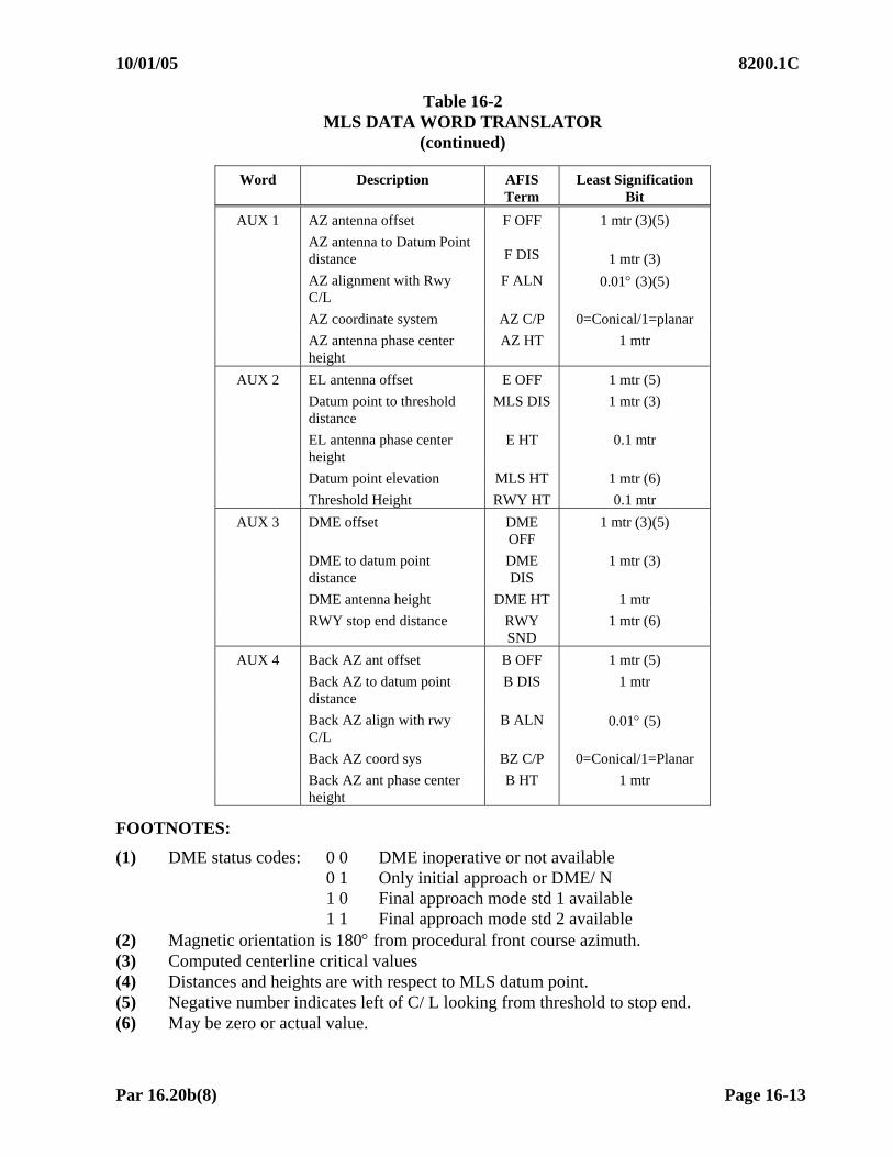
10/01/05 8200.1C
Par 16.20b(8) Page 16-13
Table 16-2 MLS DATA WORD TRANSLATOR
(continued)
FOOTNOTES:
(1) DME status codes: 0 0 DME inoperative or not available 0 1 Only initial approach or DME/ N 1 0 Final approach mode std 1 available 1 1 Final approach mode std 2 available
(2) Magnetic orientation is 180 from procedural front course azimuth. (3) Computed centerline critical values (4) Distances and heights are with respect to MLS datum point. (5) Negative number indicates left of C/ L looking from threshold to stop end. (6) May be zero or actual value.
Word Description AFIS Term
Least Signification Bit
AUX 1 AZ antenna offset F OFF 1 mtr (3)(5)
AZ antenna to Datum Point distance
F DIS
1 mtr (3)
AZ alignment with Rwy C/L
F ALN 0.01 (3)(5)
AZ coordinate system AZ C/P 0=Conical/1=planar
AZ antenna phase center height
AZ HT 1 mtr
AUX 2 EL antenna offset E OFF 1 mtr (5)
Datum point to threshold distance
MLS DIS 1 mtr (3)
EL antenna phase center height
E HT 0.1 mtr
Datum point elevation MLS HT 1 mtr (6)
Threshold Height RWY HT 0.1 mtr
AUX 3 DME offset DME OFF
1 mtr (3)(5)
DME to datum point distance
DME DIS
1 mtr (3)
DME antenna height DME HT 1 mtr
RWY stop end distance RWY SND
1 mtr (6)
AUX 4 Back AZ ant offset B OFF 1 mtr (5)
Back AZ to datum point distance
B DIS 1 mtr
Back AZ align with rwy C/L
B ALN 0.01 (5)
Back AZ coord sys BZ C/P 0=Conical/1=Planar
Back AZ ant phase center height
B HT 1 mtr
8200.1C 10/01/05
Page 16-14 Par 16.21
16.21 ANALYSIS
a. Azimuth PFE, PFN, and CMN will be evaluated over any 40-second interval of radial flight within the coverage area. Measured parameters must be in tolerance for no less than 95% of the interval measured. PFE tolerances must only be applied with use of AFIS or RTT.
b. Elevation PFE, PFN, and CMN will be evaluated over any 10-second interval of
radial flight within the coverage area at or above 0.9. Measured parameters must be in tolerance for no less than 95% of the interval measured. PFE tolerances must only be applied with use of AFIS or RTT when flown radially.
c. Manual analysis of PFN can be determined by measuring the signal deviations
from the mean azimuth or elevation angle that have a duration greater than:
(1) 6.3 seconds for azimuth
(2) 2 seconds for elevation d. Manual analysis of CMN can be determined by measuring the signal deviations
from the mean azimuth or elevation angle that have a duration less than:
(1) 10.4 seconds for azimuth
(2) 6.3 seconds for elevation
(3) CMN filter bandpass frequency overlaps a portion of the PFE bandpass frequency. The resultant CMN signal will be superimposed upon the PFE component, resulting in a larger error than is actually present. CMN must be reported after subtraction of the PFE component.
e. Monitor limits are determined by the maximum PFE found in the alarm
configurations. If monitors are checked airborne, make separate runs, measuring PFE in each configuration. If the AZ alignment monitor is checked on the ground, algebraically add the amount of alignment change to the PFE value found on the normal approach.
10/01/05 8200.1C
Par 16.22 Page 16-15
16.22 TOLERANCES
a. Facility Error Budgets. Due to the unique siting requirements of each MLS installation and the resulting difference in tolerances, a MLS error budget must be computed for each facility. The location of the azimuth site determines the Reference Point to be used in the computation of the error budget. The EL error budget reference point must coincide with the AZ.
(1) ARD when the azimuth is sited along or within 1.00 of runway centerline. (See Figure 16-3), and a 200 ft or less Decision Altitude is published.
(2) 100 ft below the MAP when the azimuth is:
(a) Sited along or within 1.00 of runway centerline (See Figure 16-3),
and a Decision Altitude above 200 ft is published.
(b) Offset. (See Figure16-4).
NOTE: Azimuth antennas installed with a distance to Missed Approach Point/ Decision Altitude greater than 9,115 ft must have a tolerance of 0.11 for PFN and 0.22 for PFE applied at the MAP.
(c) Co-located azimuth with elevation. (See Figure 16-5).
(d) Heliports which are considered to be those facilities with less than 2,300 ft between the azimuth and the approach reference datum when sited along runway centerline.
(e) Non-precision approach aid terminating at a point in space and not aligned with a precision runway. (See Figure 16-6.)
b. Application of Tolerance Degradation Factors. Tolerances are specified as the
calculated or standard value at the reference point, either ARD or MAP. As shown in Table 16-3, these tolerances may be widened (in most cases to an indicated maximum value) by the indicated degradation factors with increasing distance, lateral, or elevation displacement from the reference point. To calculate azimuth tolerance at a given point, use the following steps, in order:
(1) Determine the tolerance at the reference point, using the formula in Appendix 2.
(2) Define the measurement point in distance, lateral angle, and elevation
angle from the reference point

8200.1C 10/01/05
Page 16-16 Par 16.22b(3)
(3) C/ L Distance Degraded Tolerance
(a) Multiply the tolerance at the reference point by the distance degradation factor. This gives the maximum boresight tolerance at 20 nm.
(b) Subtract the tolerance at the reference point from the tolerance at 20 nm. This gives the maximum degradation.
(c) Divide the maximum degradation by 20, giving the degradation increment (degrees per nm).
(d) Multiply the degradation increment by the mileage from ARD of the measurement point, then add the original tolerance at the reference point. The result is the tolerance on C/ L (boresight) at the distance of the measurement point.
(4) Laterally Degraded Tolerance
(a) Multiply the distance degraded tolerance from Step (3)(d) above by the off-course degradation factor, giving the maximum degradation at 40 (60) at the specified distance.
(b) Subtract the C/ L value from the value at 40. The result is the
maximum degradation. (c) Divide the maximum degradation by 40 to get the degradation
Increment (degrees per degree). (d) Multiply the degradation increment by the number of degrees off-
course at the measurement point; add this value to the value from Step (3)(d) above. This gives the tolerance at the measurement distance and lateral offset.
(5) Vertically Degraded Tolerance (above 9 only).
(a) Multiply the distance and laterally degraded tolerance from Step
(4)(d) above by the vertical degradation factor, giving the maximum tolerance at 15 elevation at the specified distance and lateral offset.
(b) Subtract the distance and laterally degraded value (Step (4)(d)). The
result is the maximum degradation. (c) Divide the maximum degradation by the number of degrees
difference from the MGP and 15 to get the degradation increment (degrees per degree). (d) Multiple the degradation increment by the number of degrees above
the MGP at the measurement point; add this value to the value from (4)(d). This gives the tolerance degraded by all three factors.

10/01/05 8200.1C
Par 16.22b(6) Page 16-17
(6) The tolerance to be applied is the greater of either the value calculated above, or the maximum, as listed in the individual facilities listed below.
EXAMPLE: Given: AZ to ARD distance – 7,965 ft, MGP – 3.0 PFE tolerance at ARD from Paragraph 16.22e – 20 ft
Find: AZ PFE tolerance at 14 nm from ARD, @ 10 off-course, @ 12
Table 16-3 Tolerance Degradation Computation
14b step Calculation Result Definition
(1) Arctan (20 / 7,965) 0.1438 Tolerance at ARD
(3)(a) (0.1438 x 1.2) 0.1726 Tolerance @ 20 nm on C/L @ 3.00 (3)(b) (0.1726 – 0.1438) 0.0288 Maximum Degradation
(3)(c) (0.0288 / 20 nm) 0.0014 per nm Degradation Increment
(3)(d) (0.0014 x 14 nm) + 0.1438 0.01634 Tolerance @ 14 nm on C/L @ 3.00 (4)(a) (0.1634 x 1.5) 0.2451 Tolerance @ 14 nm @ 40 (4)(b) (0.2451 – 0.1634) 0.0817 Maximum Degradation
(4)(c) (0.0817 / 40) 0.0020 per degree Degradation Increment
(4)(d) (0.0020 x 10) + 0.1634 0.1834 Tolerance @ 14 nm @ 10 @ 3.00 (5)(a) (0.1834 x 1.5) 0.2751 Tolerance @ 14 nm @ 10 @ 15 (5)(b) (0.2751 – 0.1834) 0.0917 Maximum Degradation
(5)(c) (0.0917 / 12) 0.0076 Degradation Increment
(5)(d) (0.0076 x 9) + 0.1834 0.2518 Tolerance @ 14nm @ 10 @ 12
c. Standby Equipment must meet the same tolerances as the primary equipment.
d. Alignment must be reported as the average flight inspection angle. Facilities
found with an alignment that exceeds 60% of the allowable PFE must generate a maintenance alert IAW Paragraph 15.51e.
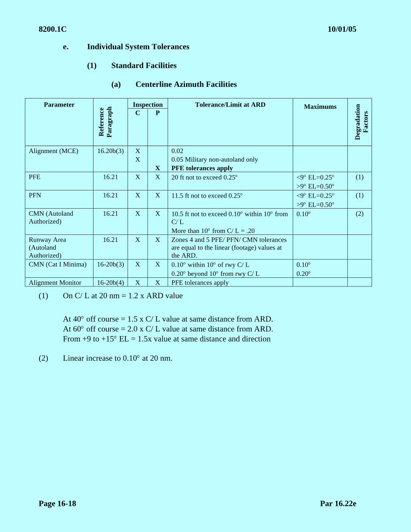
8200.1C 10/01/05
Page 16-18 Par 16.22e
e. Individual System Tolerances
(1) Standard Facilities
(a) Centerline Azimuth Facilities
Inspection Parameter R
efer
ence
P
arag
rap
h
C P Tolerance/Limit at ARD Maximums
Deg
rad
atio
n
Fac
tors
Alignment (MCE) 16.20b(3) X 0.02 X 0.05 Military non-autoland only X PFE tolerances apply PFE 16.21 X X 20 ft not to exceed 0.25 <9 EL=0.25 (1) >9 EL=0.50 PFN 16.21 X X 11.5 ft not to exceed 0.25 <9 EL=0.25 (1) >9 EL=0.50 CMN (Autoland Authorized)
16.21 X X 10.5 ft not to exceed 0.10 within 10 from C/ L
0.10 (2)
More than 10 from C/ L = .20 Runway Area (Autoland Authorized)
16.21 X X Zones 4 and 5 PFE/ PFN/ CMN tolerances are equal to the linear (footage) values at the ARD.
CMN (Cat I Minima) 16-20b(3) X X 0.10 within 10 of rwy C/ L 0.20 beyond 10 from rwy C/ L
0.10 0.20
Alignment Monitor 16-20b(4) X X PFE tolerances apply
(1) On C/ L at 20 nm = 1.2 x ARD value
At 40 off course = 1.5 x C/ L value at same distance from ARD. At 60 off course = 2.0 x C/ L value at same distance from ARD. From +9 to +15 EL = 1.5x value at same distance and direction
(2) Linear increase to 0.10 at 20 nm.

10/01/05 8200.1C
Par 16.22e Page 16-19
(b) Offset Azimuth, Azimuth Collocated with Elevation, and Heliport Azimuth Facilities
Parameter Inspection
Ref
eren
ce
Par
agra
ph
C P Tolerance/Limit @
Reference Point
Maximums
Deg
rad
atio
n
Fac
tors
Alignment (MCE) 16.20b(3) X 0.02
X PFE tolerances apply
PFE 16.21 X X 28 ft not to exceed 0.50 0.50 (1)
PFN 16.21 X X 14 ft not to exceed 0.50 0.50 (1)
CMN 16.21 X X 0.20 0.20
Alignment Monitor 16.20b(4) X X PFE tolerances apply
(1) On procedural C/ L at 20 nm=1.2 x Reference Point value
At 40 off course = 1.5 x procedural C/ L value at same distance from Reference Point
From +9 to +15 EL = 1.5 x value at same distance and direction from Reference Point
(c) Azimuth and Elevation Facilities Not Aligned as a Precision
Approach Aid to a Runway
Parameter Inspection
Ref
eren
ce
Par
agra
ph
C P Tolerance/Limit @
Reference Point
Maximums
Deg
rad
atio
n
Fac
tors
Alignment (MCE) 16.20b(3) X X (1)
PFE 16.21 No requirements
PFN 16.21 X X 0.50 None
CMN 16.21 X X 0.20 None
(1) Alignment must be considered satisfactory when the flight inspector determines that the azimuth on course and elevation rate of descent allow safe completion of the procedure as published.

8200.1C 10/01/05
Page 16-20 Par 16.22e
(d) Elevation
Inspection Parameter
Ref
eren
ce
Par
agra
ph
C P Tolerance/Limit @ 3.0
@ Reference Point Maximums
Deg
rad
atio
n
Fac
tors
Alignment (MCE) X 0.02 16.20b(3) X PFE tolerances apply PFE 16.21 X X 0.133 (1) (2) (5) PFN 16.21 X X 0.087 (1) (2) (5) CMN (autoland authorized)
X X 0.05 Within 10 of rwy C/ L = 0.10
(3) (4)
16.21 Beyond 10 of rwy C/ L = 0.20
CMN (Cat I minima) X X 0.10 Within 10 of rwy C/ L = 0.10
16.20b(3) Beyond 10 of rwy C/ L = 0.20
Alignment Monitor 16.20b(4) X X PFE tolerances apply
(1) On C/ L at 20 nm = 1.2 x ARD value (2) At 40 off course = 1.2 x C/ L value at same distance from Reference Point
At +15 EL = 2.0 x value at same distance and direction from Reference Point
(3) Linear increase to 0.10 at 20 nm (4) At 40 off course = 2.0 x C/ L value at same distance from Reference Point (5) With decreasing elevation angle: The PFE and PFN limits from +3 (or 60% of the
MGP, whichever is less) to the coverage extreme, are degraded linearly by a factor of 3 times the value at the Reference Point.

10/01/05 8200.1C
Par 16.22f Page 16-21
f. Data Words. The AFIS is the reference for the correctness of the received data words (data sheet for non-AFIS). Due to calculation rounding and feet/ meter conversion, some apparent errors occur. When the received data words do not match the AFIS expected values, the differences must be resolved with Facilities Maintenance. The following data words, if transmitted, have acceptable tolerances; all other values must match.
(1) Basic Data Words
Word Description Tolerance Basic 1 AZ to threshold distance 1 Meter Basic 3 DME distance 1 Meter
(2) Auxiliary Data Words
Word Description Tolerance AUX 1 Az to Offset 1 Meter Az to MDPT 1 Meter Az Ant Height 1 Meter AUX 2 El Ant Offset 1 Meter MDPT Distance 1 Meter El Ant Height 0.1 Meter MDPT Height 1 Meter Threshold Height 0.1 Meter AUX 3 DME Offset 1 Meter DME to MDPT Distance 1 Meter DME Ant Height 1 Meter Rwy Stop End Distance 1 Meter
8200.1C 10/01/05
Page 16-22 Par 16.30
SECTION 3. MOBILE MICROWAVE LANDING SYSTEM (MMLS) 16.30 INTRODUCTION
a. The MMLS is a tactical landing aid designed for rapid installation. MMLS may be installed in a split-site configuration or, more commonly, in a collocated configuration. The split-site configuration is essentially the same as any other MLS installation, requiring no special procedures other than for coverage checks. For split-site installations, the standard flight inspection procedures of Paragraph 16.20b are used.
b. In the collocated configuration, the Azimuth (AZ) and DME are sited with the elevation (EL) and provide a computed centerline approach for a normal runway or assault landing zone (ALZ). The antenna is typically 150 to 300 ft from centerline with distance from threshold dependent upon desired Minimum Glide Path (MGP). The AZ guidance is boresighted parallel with procedural centerline.
c. Procedural centerline is usually runway centerline, but unusual siting conditions may cause an offset situation. The standard flight inspection receiver will see the course as parallel to the procedural centerline and will not be guided to the runway. In the collocated configuration, a specialized receiver (e.g., CMLSA or multi-mode Receiver) capable of developing a “Computed Centerline,” uses the AZ and DME to compute a procedural centerline based upon the facility data words. For a collocated facility providing a computed centerline, the procedures of Paragraph 16.32 are used.
d. The MMLS does not transmit a clearance signal and will be restricted laterally if the proportional guidance limits are reduced from the normal 40. MMLS facilities are designed for 15 nm service volume. In addition, the RF power of the MMLS is monitored but not adjustable. The 20 nm checks flown at the normal RF power will simulate the power alarm condition. All DOD MMLS facilities must be restricted beyond 15 nm. Standard service volume and the coverage checks may be further reduced to 2 nm greater than the farthest procedural need; the facility must be restricted beyond the checked distance. Most restrictions will be due to reflections or signal screening. These restrictions should be placed at the distance of occurrence. If an MMLS is confirmed to have inadequate signal strength, it must be restricted beyond a distance equal to 0.75 times the distance of the out-of-tolerance signal.

10/01/05 8200.1C
Par 16.31 Page 16-23
16.31 CHECKLIST MOBILE MLS
INSPECTION
ANTENNA CHANGE
CEU CHANGE (1)(2)(3)
DEU CHANGE
MEASUREMENTS REQUIRED
TYPE CHECK
RE
FE
RE
NC
E P
AR
AG
RA
PH
C2 P2 FC* AZ EL
CO
NF
IGU
RA
TIO
N
ST
RU
CT
UR
E
AL
IGN
ME
NT
DA
TA
CO
VE
RA
GE
Data Word Verification
16.32e X X X X X X Norm X
Lat Covg 16.32a X X X X (5) Norm X X
Vert Covg 16.32b X X X Norm X X
Ref Arc 16.32a X X X X X Norm X X X
Approach AZ 16.20b(3) X, X X X X (6) Norm X X X
Approach EL 16.20b(3) X X X X X (6) Norm X X
AZ Monitor 16.20b(4) 16.32d
X (1) X Align Ref
X
EL Monitor 16.20b(4) X (1) X Hi Angle X
16.32d X (1) X Lo Angle X (4)
DME 16.20b(7) 16.32g
X X X Norm X
Ident 16.20b(6) 16.32f
X X X X Norm X
Computed Centerline Validation
16.32c X Norm X
NOTES: (1) Engineering or maintenance request
(2) Commissioning of MMLS facilities with backup CEU(s), perform Periodic and “CEU Change” checklists on backup CEU.
(3) MMLS Redeployment. If the system was removed and reinstalled in its previous configuration and exact location with no changes, perform a “P” and “CEU Change” Checklist.
(4) Coverage below path. Required on commissioning-type inspections.
(5) 20 nm coverage arc required
(6) Azimuth/ Elevation analysis is not required for a DEU change; evaluate the DME with the aircraft configured on the approach.
*FC = Frequency Change

8200.1C 02/01/07 CHG 1
Page 16-24 Par 16.32
16.32 Detailed Procedures for Collocated MMLS Providing Computed Centerline Approach. The procedures for inspecting standard MLS installations contained in Paragraph 16.20b are modified as necessary to support computed centerline approaches. Use those procedures except as directed below.
a. Coverage Arcs. Arcs are flown only to measure the proportional guidance limits. The minimum limit on the equipment side of the runway is 10 beyond the published front course azimuth. On the other side, the minimum is the greater of either 10 beyond the azimuth from the MAP to the AZ antenna OR 5 beyond the azimuth from the threshold to the AZ antenna (see Figure 16-9). See Table 16-4 for coverage arc altitudes. EXCEPTION: For ALZ operations where touchdown within 500 ft of threshold is essential, the non-equipment side limit may be decreased, as long as coverage is provided to at least 100 ft below Decision Altitude. To preclude difficulties with the vertical coverage check if the proportional guidance limit is set to the same value as the minimum required coverage, attempt to widen the proportional guidance at least an additional 2.
Table 16-4 MMLS REFERENCE ARC ALTITUDES
MGP
ANGLE MGP
@ 20 nm
MGP x 0.75
@ 5 nm
MGP x 0.75
@ 6 nm
MGP x 0.75
@ 7 nm
MGP x 0.75
@ 8 nm
MGP x 0.75
@ 9 nm
MGP x 0.75
@ 10 nm
2.5 5659 1017 1225 1436 1648 1862 2077
2.6 5871 1056 1273 1491 1711 1933 2157
2.7 6084 1096 1321 1547 1775 2005 2237
2.8 6297 1136 1369 1603 1839 2077 2316
2.9 6509 1176 1416 1659 1903 2148 2396
3 6722 1216 1464 1714 1966 2220 2476
3.1 6935 1256 1512 1770 2030 2292 2555
3.2 7147 1295 1560 1826 2094 2363 2635
3.3 7360 1335 1608 1882 2158 2435 2715
3.4 7573 1375 1655 1937 2250 2507 2794
3.5 7786 1415 1703 1993 2285 2579 2874
4 8851 1614 1942 2272 2604 2937 3273
4.5 9917 1814 2182 2552 2923 3296 3672
5 10985 2013 2421 2831 3243 3656 4071
5.5 12054 2213 2661 3111 3562 4015 4470
6 13126 2413 2901 3391 3882 4375 4870

10/01/05 8200.1C
Par 16.32b Page 16-25
b. Vertical Coverage. Accomplish this check by a level run starting at 20 nm from the antenna. The azimuth for the vertical coverage checks on the equipment side of the runway is 10 past the published front course azimuth. On the other side, fly the farther of either 10 from antenna boresight azimuth or the minimum proportional guidance limit as described in Paragraph 16.32a. If the proportional guidance limits are set at the minimum required limits and cannot be expanded, it is permissible to fly the vertical coverage 2 inside of the minimum limits of proportional guidance. Document on the flight inspection report if these runs are flown inside of the standard azimuths. (See Figure 16-9.)
c. Computed Centerline Approaches. Techniques for checking computed centerline procedures depend on the equipment used for the checks. Some flight inspection equipment is limited to checking only the antenna boresight signal while others can evaluate the computed centerline.
(1) If the flight inspection equipment is capable of determining structure and alignment of the computed centerline and elevation signal while flying the approach course, measure these parameters on the computed centerline IAW the AFIS manual. The procedural evaluation may be accomplished using the AFIS only if the aircraft can be navigated along the computed centerline by reference to the AFIS.
(2) If using theodolite or AFIS not capable of measuring the computed centerline, the azimuth boresight signal must be evaluated. When using theodolite, position the instrument in-line with the antenna center and use normal procedures. To inspect the azimuth boresight using AFIS, create a "pseudo runway" (see Figure16-7). The centerline of this "runway" passes throught the AZ antenna. Runway updates are through markers on centerline at each end of the "runway". The television positioning system (TVPS) must be used unless suitable visual cues are present to accurately determine centerline and runway ends. Facility data is changed in the AFIS to use the "pseudo runway" and must be used as the reference for AZ alignment and structure measurements. When using AFIS, actual, or "pseudo runway" data may be used for coverage arcs or vertical coverage checks. Coordinates of the "pseudo runway" threshold and updating method used must be documented on the commissioning report and Facility Data Sheet.
(a) MCE is determined in a 1 nm segment ending at the MAP.
(b) Analysis of the azimuth inside the MAP is for coverage only.
(3) Elevation. Actual runway data and normal procedures must be used for all elevation angle and structure validation when using theodolite or AFIS with or without computed centerline capability.
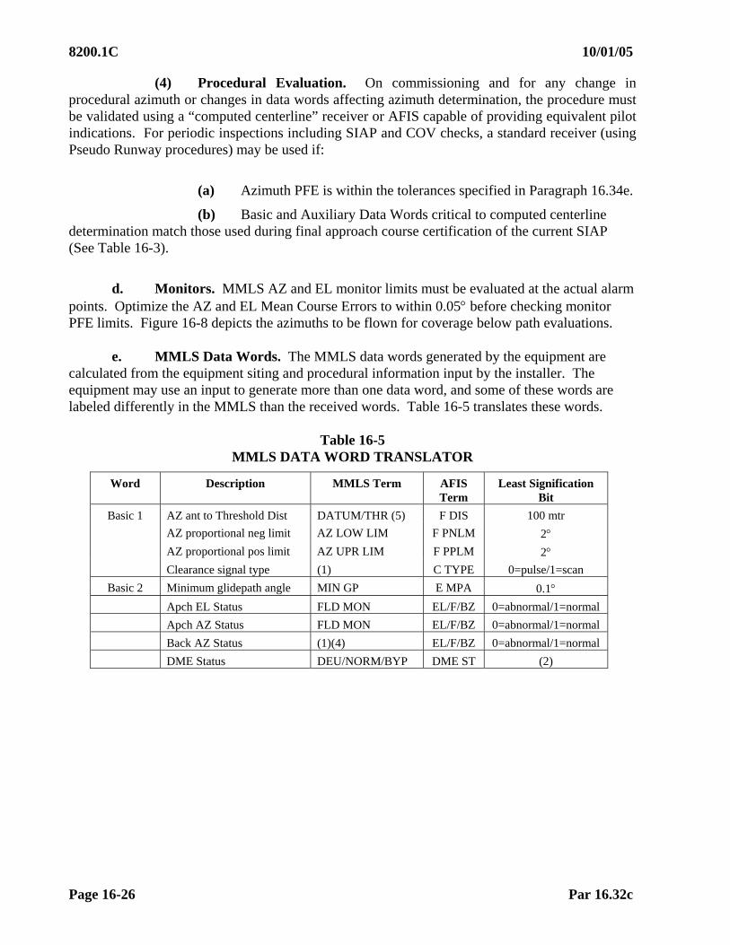
8200.1C 10/01/05
Page 16-26 Par 16.32c
(4) Procedural Evaluation. On commissioning and for any change in procedural azimuth or changes in data words affecting azimuth determination, the procedure must be validated using a “computed centerline” receiver or AFIS capable of providing equivalent pilot indications. For periodic inspections including SIAP and COV checks, a standard receiver (using Pseudo Runway procedures) may be used if:
(a) Azimuth PFE is within the tolerances specified in Paragraph 16.34e.
(b) Basic and Auxiliary Data Words critical to computed centerline determination match those used during final approach course certification of the current SIAP (See Table 16-3).
d. Monitors. MMLS AZ and EL monitor limits must be evaluated at the actual alarm
points. Optimize the AZ and EL Mean Course Errors to within 0.05 before checking monitor PFE limits. Figure 16-8 depicts the azimuths to be flown for coverage below path evaluations.
e. MMLS Data Words. The MMLS data words generated by the equipment are calculated from the equipment siting and procedural information input by the installer. The equipment may use an input to generate more than one data word, and some of these words are labeled differently in the MMLS than the received words. Table 16-5 translates these words.
Table 16-5
MMLS DATA WORD TRANSLATOR
Word Description MMLS Term AFIS Term
Least Signification Bit
Basic 1 AZ ant to Threshold Dist DATUM/THR (5) F DIS 100 mtr
AZ proportional neg limit AZ LOW LIM F PNLM 2 AZ proportional pos limit AZ UPR LIM F PPLM 2 Clearance signal type (1) C TYPE 0=pulse/1=scan
Basic 2 Minimum glidepath angle MIN GP E MPA 0.1 Apch EL Status FLD MON EL/F/BZ 0=abnormal/1=normal
Apch AZ Status FLD MON EL/F/BZ 0=abnormal/1=normal
Back AZ Status (1)(4) EL/F/BZ 0=abnormal/1=normal
DME Status DEU/NORM/BYP DME ST (2)
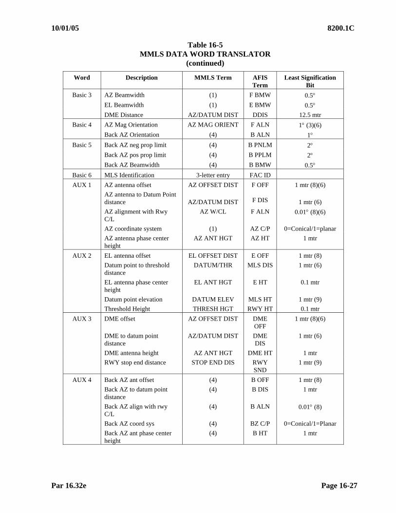
10/01/05 8200.1C
Par 16.32e Page 16-27
Table 16-5 MMLS DATA WORD TRANSLATOR
(continued)
Word Description MMLS Term AFIS Term
Least Signification Bit
Basic 3 AZ Beamwidth (1) F BMW 0.5 EL Beamwidth (1) E BMW 0.5 DME Distance AZ/DATUM DIST DDIS 12.5 mtr
Basic 4 AZ Mag Orientation AZ MAG ORIENT F ALN 1 (3)(6)
Back AZ Orientation (4) B ALN 1 Basic 5 Back AZ neg prop limit (4) B PNLM 2
Back AZ pos prop limit (4) B PPLM 2 Back AZ Beamwidth (4) B BMW 0.5
Basic 6 MLS Identification 3-letter entry FAC ID
AUX 1 AZ antenna offset AZ OFFSET DIST F OFF 1 mtr (8)(6)
AZ antenna to Datum Point distance
AZ/DATUM DIST
F DIS
1 mtr (6)
AZ alignment with Rwy C/L
AZ W/CL F ALN 0.01 (8)(6)
AZ coordinate system (1) AZ C/P 0=Conical/1=planar
AZ antenna phase center height
AZ ANT HGT AZ HT 1 mtr
AUX 2 EL antenna offset EL OFFSET DIST E OFF 1 mtr (8)
Datum point to threshold distance
DATUM/THR MLS DIS 1 mtr (6)
EL antenna phase center height
EL ANT HGT E HT 0.1 mtr
Datum point elevation DATUM ELEV MLS HT 1 mtr (9)
Threshold Height THRESH HGT RWY HT 0.1 mtr
AUX 3 DME offset AZ OFFSET DIST DME OFF
1 mtr (8)(6)
DME to datum point distance
AZ/DATUM DIST DME DIS
1 mtr (6)
DME antenna height AZ ANT HGT DME HT 1 mtr
RWY stop end distance STOP END DIS RWY SND
1 mtr (9)
AUX 4 Back AZ ant offset (4) B OFF 1 mtr (8)
Back AZ to datum point distance
(4) B DIS 1 mtr
Back AZ align with rwy C/L
(4) B ALN 0.01 (8)
Back AZ coord sys (4) BZ C/P 0=Conical/1=Planar
Back AZ ant phase center height
(4) B HT 1 mtr
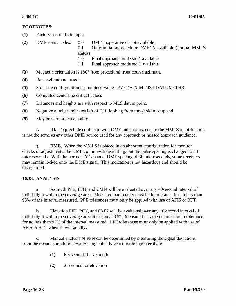
8200.1C 10/01/05
Page 16-28 Par 16.32e
FOOTNOTES:
(1) Factory set, no field input
(2) DME status codes: 0 0 DME inoperative or not available 0 1 Only initial approach or DME/ N available (normal MMLS status) 1 0 Final approach mode std 1 available 1 1 Final approach mode std 2 available
(3) Magnetic orientation is 180 from procedural front course azimuth.
(4) Back azimuth not used.
(5) Split-site configuration is combined value: AZ/ DATUM DIST DATUM/ THR
(6) Computed centerline critical values
(7) Distances and heights are with respect to MLS datum point.
(8) Negative number indicates left of C/ L looking from threshold to stop end.
(9) May be zero or actual value.
f. ID. To preclude confusion with DME indications, ensure the MMLS identification is not the same as any other DME source used for any approach or missed approach guidance.
g. DME. When the MMLS is placed in an abnormal configuration for monitor checks or adjustments, the DME continues transmitting, but the pulse spacing is changed to 33 microseconds. With the normal “Y” channel DME spacing of 30 microseconds, some receivers may remain locked onto the DME signal. This indication is not hazardous and should be disregarded. 16.33. ANALYSIS
a. Azimuth PFE, PFN, and CMN will be evaluated over any 40-second interval of radial flight within the coverage area. Measured parameters must be in tolerance for no less than 95% of the interval measured. PFE tolerances must only be applied with use of AFIS or RTT.
b. Elevation PFE, PFN, and CMN will be evaluated over any 10-second interval of
radial flight within the coverage area at or above 0.9. Measured parameters must be in tolerance for no less than 95% of the interval measured. PFE tolerances must only be applied with use of AFIS or RTT when flown radially.
c. Manual analysis of PFN can be determined by measuring the signal deviations
from the mean azimuth or elevation angle that have a duration greater than:
(1) 6.3 seconds for azimuth (2) 2 seconds for elevation
10/01/05 8200.1C
Par 16.33d Page 16-29
d. Manual analysis of CMN can be determined by measuring the signal deviations from the mean azimuth or elevation angle that have a duration less than:
(1) 10.4 seconds for azimuth (2) 6.3 seconds for elevation (3) CMN filter bandpass frequency overlaps a portion of the PFE bandpass
frequency. The resultant CMN signal will be superimposed upon the PFE component, resulting in a larger error than is actually present. CMN must be reported after subtraction of the PFE component.
e. Monitor limits are determined by the maximum PFE found in the alarm
configurations. If monitors are checked airborne, make separate runs, measuring PFE in each configuration. If the AZ alignment monitor is checked on the ground, algebraically add the amount of alignment change to the PFE value found on the normal approach. 16.34 TOLERANCES
a. Facility Error Budgets. An MMLS error budget must be computed in the same manner as one done for an MLS. Due to the unique siting requirements of each MMLS installation and the resulting difference in tolerances, an MLS error budget must be computed for each facility. The location of the azimuth site determines the reference point to be used in the computation of the error budget. The EL error budget reference point must coincide with the AZ.
(1) ARD when the azimuth is sited along or within 1.00 of runway centerline
(See Figure 16-3), and a 200 ft or less Decision Altitude is published. (2) 100 ft below the MAP when the azimuth is:
(a) Sited along or within 1.00 of runway centerline (See Figure 16-3), and a Decision Altitude above 200 ft is published.
(b) Offset. (See Figure 16-4).
NOTE: Azimuth antennas installed with a distance to Missed Approach Point/ Decision Altitude greater than 9,115 ft must have a tolerance of 0.11 for PFN and 0.22 for PFE applied at the MAP.
(c) Co-located azimuth with elevation. (See Figure 16-5).
(d) Heliports which are considered to be those facilities with less than 2,300 ft between the azimuth and the approach reference datum when sited along runway centerline.
(e) Non-precision approach aid terminating at a point in space and not aligned with a precision runway. (See Figure 16-6.)

8200.1C 10/01/05
Page 16-30 Par 16.34b
b. Application of Tolerance Degradation Factors. Tolerances are specified as the calculated or standard value at the reference point, either ARD or MAP. These tolerances may be widened (in most cases to an indicated maximum value) by the indicated degradation factors with increasing distance, lateral, or elevation displacement from the reference point. As shown in Table 16-6, to calculate azimuth tolerance at a given point, use the following steps, in order:
(1) Determine the tolerance at the reference point, using the formula in
Appendix 2. (2) Define the measurement point in distance, lateral angle, and elevation
angle from the reference point. (3) C/ L Distance Degraded Tolerance
(a) Multiply the tolerance at the reference point by the distance degradation factor. This gives the maximum boresight tolerance at 20 nm.
(b) Subtract the tolerance at the reference point from the tolerance at
20 nm. This gives the maximum degradation. (c) Divide the maximum degradation by 20, giving the degradation
increment (degrees per nm). (d) Multiply the degradation increment by the mileage from ARD of the
measurement point, then add the original tolerance at the reference point. The result is the tolerance on C/ L (boresight) at the distance of the measurement point.
(4) Laterally Degraded Tolerance
(a) Multiply the distance degraded tolerance from Step (3)(d) above by the off-course degradation factor, giving the maximum degradation at 40 (60) at the specified distance.
(b) Subtract the C/ L value from the value at 40. The result is the
maximum degradation. (c) Divide the maximum degradation by 40 to get the degradation
increment (degrees per degree). (d) Multiply the degradation increment by the number of degrees off-
course at the measurement point; add this value to the value from Step (3)(d) above. This gives the tolerance at the measurement distance and lateral offset.
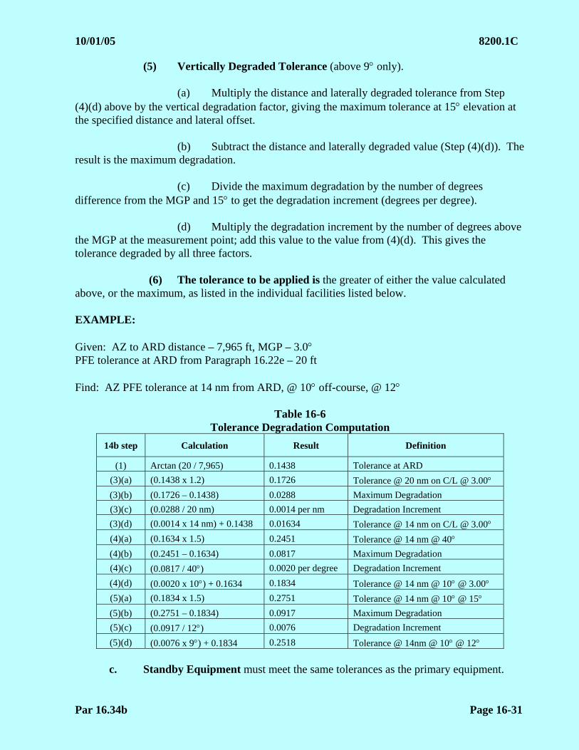
10/01/05 8200.1C
Par 16.34b Page 16-31
(5) Vertically Degraded Tolerance (above 9 only).
(a) Multiply the distance and laterally degraded tolerance from Step (4)(d) above by the vertical degradation factor, giving the maximum tolerance at 15 elevation at the specified distance and lateral offset.
(b) Subtract the distance and laterally degraded value (Step (4)(d)). The
result is the maximum degradation. (c) Divide the maximum degradation by the number of degrees
difference from the MGP and 15 to get the degradation increment (degrees per degree). (d) Multiply the degradation increment by the number of degrees above
the MGP at the measurement point; add this value to the value from (4)(d). This gives the tolerance degraded by all three factors.
(6) The tolerance to be applied is the greater of either the value calculated
above, or the maximum, as listed in the individual facilities listed below.
EXAMPLE: Given: AZ to ARD distance – 7,965 ft, MGP – 3.0 PFE tolerance at ARD from Paragraph 16.22e – 20 ft Find: AZ PFE tolerance at 14 nm from ARD, @ 10 off-course, @ 12
Table 16-6 Tolerance Degradation Computation
14b step Calculation Result Definition
(1) Arctan (20 / 7,965) 0.1438 Tolerance at ARD
(3)(a) (0.1438 x 1.2) 0.1726 Tolerance @ 20 nm on C/L @ 3.00 (3)(b) (0.1726 – 0.1438) 0.0288 Maximum Degradation
(3)(c) (0.0288 / 20 nm) 0.0014 per nm Degradation Increment
(3)(d) (0.0014 x 14 nm) + 0.1438 0.01634 Tolerance @ 14 nm on C/L @ 3.00 (4)(a) (0.1634 x 1.5) 0.2451 Tolerance @ 14 nm @ 40 (4)(b) (0.2451 – 0.1634) 0.0817 Maximum Degradation
(4)(c) (0.0817 / 40) 0.0020 per degree Degradation Increment
(4)(d) (0.0020 x 10) + 0.1634 0.1834 Tolerance @ 14 nm @ 10 @ 3.00 (5)(a) (0.1834 x 1.5) 0.2751 Tolerance @ 14 nm @ 10 @ 15 (5)(b) (0.2751 – 0.1834) 0.0917 Maximum Degradation
(5)(c) (0.0917 / 12) 0.0076 Degradation Increment
(5)(d) (0.0076 x 9) + 0.1834 0.2518 Tolerance @ 14nm @ 10 @ 12
c. Standby Equipment must meet the same tolerances as the primary equipment.

8200.1C 02/01/07 CHG 1
Page 16-32 Par 16.34d
d. Alignment must be reported as the average flight inspection angle. Facilities found with an alignment that exceeds 60% of the allowable PFE must generate a maintenance alert IAW Paragraph 15.51e. Facilities must not be NOTAMed unless the PFE allowance at the reference point is exceeded.
e. Individual System Tolerances
(1) MMLS Facilities Authorized for no Lower than Category I Minima Use by Military Aircraft Only
(2) Facilities checked using these tolerances must be restricted. If applicable,
the flight inspection reports must be annotated IAW Chapter 24.
(3) Split-Site Centerline Azimuth
Inspection Tolerance/Limit at ARD Parameter
Ref
ern
ce
Par
agra
ph
C P Maximums
Deg
rad
atio
n
Fac
tors
Alignment (MCE) X 0.05 16.20b(3) X PFE tolerances apply PFE 16.21 X X 28 ft not to exceed 0.50 0.50 (1)
PFN 16.21 X X 14 ft not to exceed 0.50 0.50 (1)
CMN 16.20b(3) X X 0.20
Alignment Monitor 16.20b(4) X X PFE tolerances apply
(1) On C/ L at 20 nm = 1.2 x MAP value
(4) Azimuth Collocated with Elevation
Parameter Inspection
Ref
eren
ce
Par
agra
ph
C P Tolerance/Limit @
Reference Point Maximums
Deg
rad
atio
n
Fac
tors
Alignment (MCE) 16.20b(3) X 0.05 X PFE tolerances apply PFE 16.21 X X 35 ft not to exceed 0.50 0.50 (1) (2)
PFN 16.21 X X 66% of allowable PFE 0.50 (1) (2)
CMN 16.20b(3) X X 0.20 0.20 None
Alignment Monitor 16.20b(4) X X PFE tolerances apply
(1) On C/ L at 20 nm = 1.2 x Reference Point value (2) At 40 off course = 1.5 x C/ L value at same distance from Reference Point
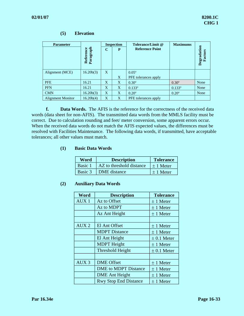
02/01/07 8200.1C CHG 1
Par 16.34e Page 16-33
(5) Elevation
Parameter Inspection
Ref
eren
ce
Par
agra
ph
C P Tolerance/Limit @
Reference Point Maximums
Deg
rad
atio
n
Fac
tors
Alignment (MCE) 16.20b(3) X 0.05 X PFE tolerances apply PFE 16.21 X X 0.30 0.30 None
PFN 16.21 X X 0.133 0.133 None
CMN 16.20b(3) X X 0.20 0.20 None
Alignment Monitor 16.20b(4) X X PFE tolerances apply
f. Data Words. The AFIS is the reference for the correctness of the received data
words (data sheet for non-AFIS). The transmitted data words from the MMLS facility must be correct. Due to calculation rounding and feet/ meter conversion, some apparent errors occur. When the received data words do not match the AFIS expected values, the differences must be resolved with Facilities Maintenance. The following data words, if transmitted, have acceptable tolerances; all other values must match.
(1) Basic Data Words
Word Description Tolerance Basic 1 AZ to threshold distance 1 Meter Basic 3 DME distance 1 Meter
(2) Auxiliary Data Words
Word Description Tolerance AUX 1 Az to Offset 1 Meter Az to MDPT 1 Meter Az Ant Height 1 Meter AUX 2 El Ant Offset 1 Meter MDPT Distance 1 Meter El Ant Height 0.1 Meter MDPT Height 1 Meter Threshold Height 0.1 Meter AUX 3 DME Offset 1 Meter DME to MDPT Distance 1 Meter DME Ant Height 1 Meter Rwy Stop End Distance 1 Meter
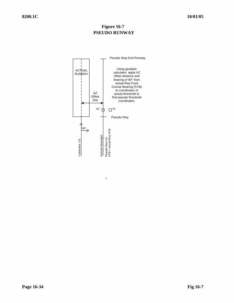
8200.1C 10/01/05
Page 16-34 Fig 16-7
Figure 16-7 PSEUDO RUNWAY
Using geodetic calculator, apply AZ offset distance and bearing of 90 from actual Rwy Front
Course Bearing (FCB) to coordinates of
actual threshold to find pseudo threshold
coordinates.
Pseudo Stop End Runway
AZ
AZ Offset Dist
Pseudo Rwy
90
ACTUAL RUNWAY
Com
pute
d C
/L
Azi
mut
h B
ores
ight
Pse
udo
Rw
y C
/L
FC
B =
Act
ua
l Rw
y F
CB
T
EL

10/01/05 8200.1C
Fig 16-8 Page 16-35
Figure 16-8
AZIMUTHS FOR COVERAGE BELOW PATH (COMPUTED CENTERLINE FACILITIES)
2
MAP
Com
pute
d C
/L
Actual Runway
Fly Dashed Line Azimuths
2
Pse
udo
Rw
y C
/L
Azi
mut
h B
ores
ight
T
Pseudo Stop End Runway
AZ
Pseudo Runway
EL
Bearings overlying MAP are on the Facility Data Sheet
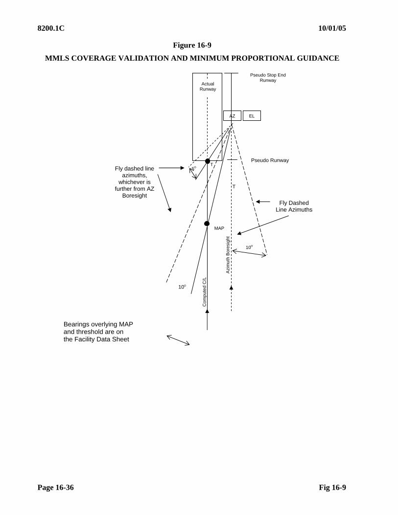
8200.1C 10/01/05
Page 16-36 Fig 16-9
Figure 16-9
MMLS COVERAGE VALIDATION AND MINIMUM PROPORTIONAL GUIDANCE
T
T
10
Com
pute
d C
/L
Azi
mut
h B
ores
ight
5
10
MAP
AZ EL
Fly dashed line azimuths,
whichever is further from AZ
Boresight
Actual Runway
Fly Dashed Line Azimuths
Pseudo Stop End Runway
Pseudo Runway
Bearings overlying MAP and threshold are on the Facility Data Sheet
5/30/11 8200.1C Chg 4
Page 17-i (and ii)
CHAPTER 17. GROUND-BASED AUGMENTATION SYSTEM (GBAS)
TABLE OF CONTENTS
Paragraphs Title Pages
17.10 INTRODUCTION .............................................................................17-1 17.11 PREFLIGHT REQUIREMENTS ......................................................17-2
a. Inspection System Calibration ...............................................17-2 b. Dmax Determination................................................................17-2 c. GBAS Position, Velocity, and Time (PVT) Mode ................17-2 d. GBAS FAS Data Block Validation........................................17-3 e. GBAS Supporting Parallel Runways .....................................17-3 f. GBAS Supporting TAP Procedures (Reserved) ....................17-3 g. GBAS Supporting Airport Surface Operations (Reserved) ...17-3
17.12 FLIGHT INSPECTION PROCEDURES..........................................17-6
a. Checklist ................................................................................17-6 b. GBAS VDB Coverage ...........................................................17-7 c. Aircraft Positioning................................................................17-13 d. Periodic Evaluation................................................................17-14 e. Special Evaluation .................................................................17-14 f. Flight Inspection Analysis .....................................................17-15 g. Tolerances. Flight Inspection Reference System..................17-18 h. Adjustments ...........................................................................17-18
Figures 17-1 Determining Approach Sector Centerline, FASAP, and FASLTP................17-4 17-2 Determining Right/ Left Boundary and Boundary Alignment Points ...........17-5 17-3 GBAS Coverage/ Service Volume (Courtesy RTCA DO-245).....................17-8 17-4 Approach Coverage Requirements ................................................................17-13
Tables 17-1 VDB Approach Coverage Assessment ..........................................................17-11 17-2 VDB Approach Coverage Assessment – Parallel Runways ..........................17-12

This Page Intentionally Left Blank

5/30/11 8200.1C Chg 4
Par 17.10 Page 17-1
CHAPTER 17. GROUND-BASED AUGMENTATION SYSTEM (GBAS) 17.10 INTRODUCTION. GBAS is a safety-critical system consisting of the hardware and software that augments the Global Positioning System (GPS) Standard Positioning Service (SPS) to provide precision approach and landing capability. The positioning service provided by GPS is insufficient to meet the integrity, continuity, accuracy, and availability demands of precision approach and landing navigation. GBAS provides a precision approach service and a positioning service, which provides horizontal position information to support RNAV operations in the terminal area. GBAS augments the GPS SPS in order to meet these requirements. These augmentations are based on differential GPS concepts. GBAS refers to any system compliant with the existing ICAO standards. The FAA version of GBAS is the Local Area Augmentation System (LAAS). LAAS will provide the precision approach and positioning services defined by the ICAO GBAS standards, plus additional services. LAAS focuses its service on the airport area to provide for departure, terminal, precision approach, and surface navigation operations. LAAS will yield the extremely high accuracy, availability, continuity, and integrity necessary for Category I, II, and III precision approaches. It is expected that the end-state configuration will pinpoint the aircraft’s position to within one meter or less with a significant improvement in service flexibility. GBAS is comprised of ground equipment and avionics. The ground equipment includes four reference receivers and associated antennas, an electronics cabinet, and a very high frequency (VHF) data broadcast (VDB) transmitter and associated antenna. The ground equipment is complemented by GBAS avionics installed on the aircraft. The VDB broadcasts the GBAS signal throughout the GBAS coverage area to avionics in GBAS-equipped aircraft. The GBAS reference receivers independently measure GPS satellite pseudo-range and carrier phase and generate differential carrier-smoothed-code corrections that are eventually broadcast to the user via a 31.5 kbps VHF data broadcast (in the 108 – 118 MHz band) that also includes safety and approach geometry information. Aircraft landing at a GBAS-equipped airport will be able to perform precision approach operations to at least Category I weather minima. The GBAS approach charts are titled “GLS RWY xx” (GBAS Landing System). The navigation guidance on terminal segments for the aircraft to transition into a GBAS precision approach final (or missed approach) may be provided by either RNAV or ground-based systems (e.g., VOR). Use of the appropriate chapter(s) in this order is required for flight inspection of procedural segments for obstructions, procedural design, navigation guidance, and RNAV coding. This chapter provides inspection guidance and tolerances for any system meeting ICAO GBAS minimum standards.
8200.1C 5/30/11 Chg 4
Page 17-2 Par 17.11
17.11 PREFLIGHT REQUIREMENTS. The Flight Inspector must prepare for the flight inspection in accordance with this order. For each GBAS to be evaluated, the inspector must determine the type and number of approach procedures to be supported and if approach procedures to parallel runway groups will be provided. En route and terminal procedural segments transitioning into the GBAS final may require inspection of ground facilities or Area Navigation (RNAV) segments. Refer to the appropriate chapters of this order for requirements and tolerances. Due to the criticality of data, the inspector must ensure that all required data is based upon the same reference datum (NAD83/ NAVD88, ITRF00/ WGS84, etc.). This includes the facility data sheet, proposed approach procedures, FAS Data, GBAS facility reference point (as defined on the facility data sheet and broadcast in the Type 2 message), differential GPS (if used), the runway coordinates, and elevations. Prior to mission departure, confirm Flight Inspection System (FIS) access to each individual procedural FAS data binary file and verify the cyclic redundancy check (CRC) remainder matches the FAA Form 8260-10 data (or equivalent). This ensures no errors occurred during data transfer (data file integrity). Any corruption of data during transfer must be resolved prior to conducting the inspection.
a. Inspection System Calibration. Since the VDB antenna may radiate both horizontally (GBAS/ H) and elliptically (GBAS/ E) polarized signals, the FIS will be calibrated for both polarizations. The calibration must include data for the airborne antenna pattern and cable loss.
b. Dmax Determination. The GBAS may or may not utilize a Dmax function. If applicable, determine from the airport data sheet the maximum use distance (Dmax) for precision approach and positioning service volume coverage evaluation.
c. GBAS Position, Velocity, and Time (PVT) Mode. Currently, GBAS does not provide IFR-certified (approved) PVT services; these services may be implemented in the future. If PVT services will be provided, Item (1) below will be completed prior to the flight.
(1) PVT Service Inspection: (Reserved)
(2) Enabling PVT Services. Flight inspection systems requiring the PVT services to be enabled in order for the FIS to display and collect data will require coordination with ground facility personnel to ensure the GBAS PVT services are enabled prior to starting the inspection.
Note: The ground system configuration may require up to 35 minutes for transitions between Non-PVT (PVT disabled) services and PVT services enabled.
Upon completion of the inspection, ground facility personnel must disable the PVT services and return the system to its normal operating configuration. Once the system has been restored to its normal operating configuration, a final normal approach must be performed to confirm course guidance. Course guidance verification can be completed by flying a minimum of one GLS approach.
5/30/11 8200.1C Chg 4
Par 17.11d Page 17-3
d. GBAS FAS Data Block Validation. The FAS data block consists of data elements that prescribe the precision three-dimensional geometric path in space that an aircraft will fly on final approach. Particular attention should be paid to the data accuracy in the FAS data block for GBAS flight procedures. Corruption of ellipsoid height data can have adverse effects on the FIS announced TCH value and the location of a glide path by displacing the glide path forward or aft along track of the intended procedural design.
Errors in this data can quickly lead to an unacceptable or hazardous flight path. There are several sources for data errors, with survey data errors as the most common, along with incomplete terrain and obstacle data. GBAS uses an earth-centered, earth-fixed (ECEF) reference system. Conversions between geodetic datums can induce errors. Vertical datum differences can result in positioning errors, causing the FIS announced TCH for GBAS procedures to be higher or lower than designed. It is imperative that procedural data and airport data are matched for the flight inspection and for the date of procedure publication.
e. GBAS Supporting Parallel Runways. When the GBAS to be evaluated supports approach procedures to parallel runways, approach sectors are defined. An approach sector bounds the area of airspace common to all the approach procedures having the same approach and landing direction. Thus, a set of parallel runways will have two approach sectors associated with them, one for each landing direction. The methodology for evaluation of the approach sector, as opposed to assessing each runway end individually, permits sufficient assessment of each approach procedure while improving the efficiency of the inspection by eliminating redundant VDB coverage assessments. Some parallel runway sites may not be appropriate for application of this procedure due to excessive distance between the parallels, environmental issues between the parallels, the stagger between runway thresholds, location of VDB antenna relative to the course for the procedures, etc. A thorough engineering analysis may be required for runways with separations exceeding 4,000 feet (e.g., KDFW RWY 13L/ RWY 31R and RWY 13R/ 31L) and/or when the difference in the setbacks of the runway thresholds as measured parallel to the runway centerline exceeds 2,500 feet (e.g., KAUS 17R and KAUS 17L).
(1) Determine the coordinates for both the fictitious approach sector alignment point (FASAP) and fictitious approach sector landing threshold point (FASLTP) for each approach sector. The approach sector centerline runs parallel to the runway centerlines and is located midway between the centerlines of the outer-most runways (see Figure 17-1). The FASAP and FASLTP are located abeam the furthest most runway stop end and threshold, respectively, and on the approach sector centerline as illustrated in Figure 17-1.
(2) Determining Parallel Runway Left/ Right Sector Limit Boundary (Figure 17-2).
(a) For the left-most runway: The left limit of course centerline boundary is defined by the full-scale of “fly right” on the cockpit course deviation indicator (CDI).
(b) For the right-most runway: The right limit boundary is defined by the full-scale of “fly left” on the cockpit CDI.
f. GBAS Supporting TAP Procedures. (Reserved)
g. GBAS Supporting Airport Surface Operations. (Reserved)
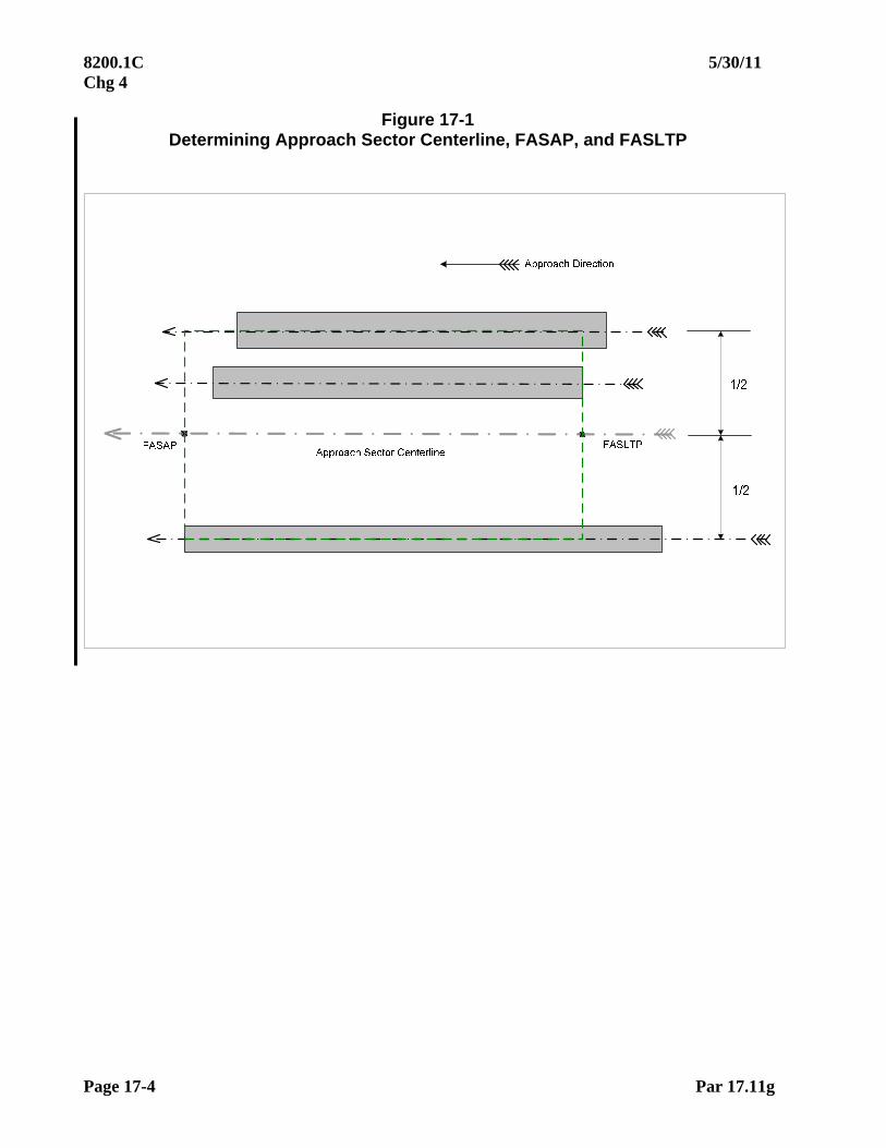
8200.1C 5/30/11 Chg 4
Page 17-4 Par 17.11g
Figure 17-1 Determining Approach Sector Centerline, FASAP, and FASLTP
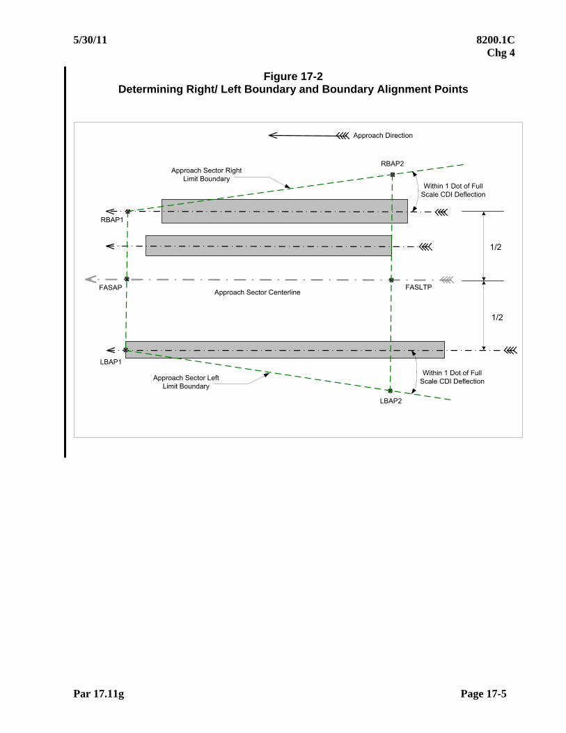
5/30/11 8200.1C Chg 4
Par 17.11g Page 17-5
Figure 17-2 Determining Right/ Left Boundary and Boundary Alignment Points
Approach Direction
Approach Sector CenterlineFASAP FASLTP
LBAP1
LBAP2
RBAP2
RBAP1
Approach Sector LeftLimit Boundary
Approach Sector RightLimit Boundary
1/2
1/2
Within 1 Dot of Full Scale CDI Deflection
Within 1 Dot of Full Scale CDI Deflection
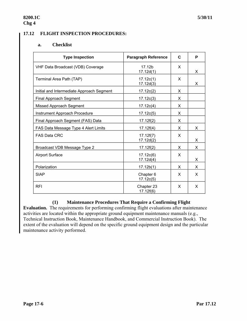
8200.1C 5/30/11 Chg 4
Page 17-6 Par 17.12
17.12 FLIGHT INSPECTION PROCEDURES:
a. Checklist
Type Inspection Paragraph Reference C P
VHF Data Broadcast (VDB) Coverage 17.12b 17.12d(1)
X
X
Terminal Area Path (TAP) 17.12c(1) 17.12d(3)
X X
Initial and Intermediate Approach Segment 17.12c(2) X
Final Approach Segment 17.12c(3) X
Missed Approach Segment 17.12c(4) X
Instrument Approach Procedure 17.12c(5) X
Final Approach Segment (FAS) Data 17.12f(2) X
FAS Data Message Type 4 Alert Limits 17.12f(4) X X
FAS Data CRC 17.12f(7) 17.12d(2)
X X
Broadcast VDB Message Type 2 17.12f(2) X X
Airport Surface 17.12c(6) 17.12d(4)
X X
Polarization 17.12b(1) X X
SIAP Chapter 6 17.12c(5)
X X
RFI Chapter 23 17.12f(6)
X X
(1) Maintenance Procedures That Require a Confirming Flight
Evaluation. The requirements for performing confirming flight evaluations after maintenance activities are located within the appropriate ground equipment maintenance manuals (e.g., Technical Instruction Book, Maintenance Handbook, and Commercial Instruction Book). The extent of the evaluation will depend on the specific ground equipment design and the particular maintenance activity performed.

5/30/11 8200.1C Chg 4
Par 17.12a Page 17-7
(2) Flight Inspection Types:
(a) Commissioning: A comprehensive evaluation of the GBAS system and Standard Instrument Approach Procedures (SIAP(s)). See checklist.
(b) Periodic. VDB coverage along the lower orbit will be based on
signal-strength assessments and loss of signal. The altitude established for the lower orbit during commissioning must be used. The GBAS broadcast FAS data block CRC must be evaluated and documented for each SIAP. Approach obstacle verification scheduling must be completed in accordance with Chapter 4.
(c) Special. A special inspection will be required when a user complaint is confirmed, an existing approach is modified, or after certain maintenance activities identified within the appropriate ground equipment maintenance manuals.
b. GBAS VDB Coverage. The service volume for GBAS is constrained by both the radio frequency (RF) signal coverage provided by the ground-based VDB antenna(s) and maximum range (Dmax) from the GBAS for which the broadcast differential corrections are applicable (See Figure 17-3). RF signal coverage refers to those regions where the signal strength is sufficient to provide continuous reception by the aircraft of the data broadcast. RF signal coverage can extend beyond the airport terminal area, dependent on the output power of the VDB transmitter, VDB antenna type, aircraft altitude, and the horizon (line-of-sight) profile about the VDB antenna site.
For LAAS, the maximum use distance, Dmax, is site dependent and determined by the operational needs and supporting analysis that ensure system integrity is met. FAA certified LAAS Ground Facilities (LGF(s)) are required to support a Dmax value of at least 23 nm. The Dmax distance is referenced to the centroid of the LGF reference receivers.

8200.1C 5/30/11 Chg 4
Page 17-8 Par 17.12b
The aircraft must be within the range defined by Dmax in order for the GBAS avionics to output differentially corrected information. That is, the GBAS differentially-corrected positioning service (i.e., PVT output) and course guidance are available when within the RF coverage volume out to the distance indicated by Dmax.
Figure 17-3
LAAS Coverage/ Service Volume (courtesy RTCA DO-245)
(1) VDB Signal Polarization. The GBAS VDB antenna radiates either a horizontally (GBAS/H) or elliptically (GBAS/E) polarized signal. This allows the data broadcast to be tailored to the operational requirements of the local airborne user community. The majority of aircraft will be equipped with a horizontally polarized VDB receive antenna, which can receive the VDB signal from either a horizontally or elliptically polarized VDB broadcast antenna. Aircraft equipped with a vertically polarized antenna will receive the vertical component of the elliptically polarized signal. Polarization is spot-checked once during the inspection and can be completed anywhere valid VDB signal is available.
(2) VDB Coverage Evaluation. The service volume of the VDB must encompass the area of intended terminal and approach operations. Since Dmax defines the outer limit of the service volume, Dmax must be set appropriately for each facility. The suitability of the value used for Dmax will be evaluated for each GBAS. In addition, RF signal (minimum power) coverage within the service volume will be evaluated for procedurally significant airspace (procedure-based coverage assessment).
VDB coverage will be evaluated based on strength assessments, loss of signal, and data continuity alerts. The GBAS will be re-configured as required for flight inspection. The power output must be at the minimum RF power alarm point. The initial coverage checks will confirm the minimum RF power alarm point. Data continuity can be verified by validating correct FIS sensor status while in the GBAS reception area and positive GBAS course guidance as indicated on the CDI. No data continuity alerts are allowed while within the VDB approach coverage assessment areas in Table 17-1.
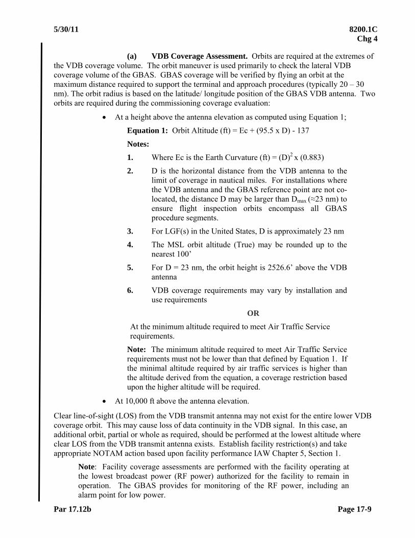
5/30/11 8200.1C Chg 4
Par 17.12b Page 17-9
(a) VDB Coverage Assessment. Orbits are required at the extremes of the VDB coverage volume. The orbit maneuver is used primarily to check the lateral VDB coverage volume of the GBAS. GBAS coverage will be verified by flying an orbit at the maximum distance required to support the terminal and approach procedures (typically 20 – 30 nm). The orbit radius is based on the latitude/ longitude position of the GBAS VDB antenna. Two orbits are required during the commissioning coverage evaluation:
At a height above the antenna elevation as computed using Equation 1;
Equation 1: Orbit Altitude (ft) = Ec + (95.5 x D) - 137
Notes:
1. Where Ec is the Earth Curvature (ft) = (D)2 x (0.883)
2. D is the horizontal distance from the VDB antenna to the limit of coverage in nautical miles. For installations where the VDB antenna and the GBAS reference point are not co-located, the distance D may be larger than Dmax (≈23 nm) to ensure flight inspection orbits encompass all GBAS procedure segments.
3. For LGF(s) in the United States, D is approximately 23 nm
4. The MSL orbit altitude (True) may be rounded up to the nearest 100’
5. For D = 23 nm, the orbit height is 2526.6’ above the VDB antenna
6. VDB coverage requirements may vary by installation and use requirements
OR
At the minimum altitude required to meet Air Traffic Service requirements.
Note: The minimum altitude required to meet Air Traffic Service requirements must not be lower than that defined by Equation 1. If the minimal altitude required by air traffic services is higher than the altitude derived from the equation, a coverage restriction based upon the higher altitude will be required.
At 10,000 ft above the antenna elevation.
Clear line-of-sight (LOS) from the VDB transmit antenna may not exist for the entire lower VDB coverage orbit. This may cause loss of data continuity in the VDB signal. In this case, an additional orbit, partial or whole as required, should be performed at the lowest altitude where clear LOS from the VDB transmit antenna exists. Establish facility restriction(s) and take appropriate NOTAM action based upon facility performance IAW Chapter 5, Section 1.
Note: Facility coverage assessments are performed with the facility operating at the lowest broadcast power (RF power) authorized for the facility to remain in operation. The GBAS provides for monitoring of the RF power, including an alarm point for low power.
8200.1C 5/30/11 Chg 4
Page 17-10 Par 17.12b
1 Facilities Broadcasting Dmax: Verify VDB data continuity, GBAS course guidance, and signal strength are satisfactory inside Dmax. Verify Dmax functionality by transitioning the aircraft beyond the designated Dmax value and verifying a data continuity alert indication and loss of GBAS course guidance. When transitioning from beyond Dmax, to inside Dmax, data continuity must transition to GBAS. Positive GBAS course guidance must be displayed when in the approach coverage assessment areas in Table 17-1. Flagged course guidance in areas of non-use should not result in a failed inspection
2 Facilities Not Broadcasting Dmax: (Reserved)
(b) Procedure Coverage Assessment. Initial coverage assessments are performed with the VDB transmitter power set at the RF power alarm point of the VDB monitor.
1 Terminal Area Path (TAP). (Reserved)
2 Approach Coverage. Table 17-1 provides the requirements for assessing VDB coverage for each approach procedure. The maneuvers listed in Table 17-1 are intended to provide assessment of the coverage requirements illustrated in Figure 17-4. For a GBAS servicing multiple runways, each approach procedure must be evaluated in accordance with Table 17-1, except for the case of parallel runways.
When the GBAS to be evaluated supports approach procedures to parallel runways, approach sectors are defined, one for each landing direction. Table 17-2 provides modified requirements for assessing parallel runway configurations. The measured values are the same as those specified in Table 17-1.
3 Airport Surface Coverage. (Reserved)

5/30/11 8200.1C Chg 4
Par 17.12b Page 17-11
Table 17-1 VDB Approach Coverage Assessment (See Notes 3 and 5)
Requirement Evaluation Area Method Evaluation Criteria
Normal Approach From 20 nm to LTP Fly on Path, on course No CDI Flags
Lower Limit of Approach From 20 nm to LTP From 21 nm and 5,000’ above GBAS, fly on course, intercept and fly glide path within 1 dot of full scale below path
No CDI Flags
Note 1
Note 2
Upper Limit of Approach From 20 nm to LTP From 21 nm and 7000’-8,000’ above GBAS, fly on course, intercept and fly glide path within 1 dot of full scale above path.
No CDI Flags
Note 1
Note 2
Left Limit of Approach Note 4 From 20 nm to LTP From 21 nm, fly on path and offset course to within 1 dot of full scale of “fly right”.
No CDI Flags
Note 2
Right Limit of Approach Note 4 From 20 nm to LTP From 21nm, fly on path and offset course to within 1 dot of full scale of “Fly left”.
No CDI Flags
Note 2
Coverage from MVA Note 4 From 20 nm to 7º glide path From 21 nm on course and the MVA or 2,500 feet above LTP, whichever is higher, fly at level altitude until 7º path.
Note: If possible, continue beyond 7º to determine extent of VDB coverage over the airport.
No CDI Flags
Note 1
Coverage from Upper Service Volume Note 4
From 20 nm to 7º glide path (13.4 nm to Glide Path Intercept Point (GPIP))
From 21 nm on course and 10,000’ above LTP, fly at level altitude until 7ºpath.
No CDI Flags
Note 1
Missed Approach From Decision Altitude to 4nm from departure end of runway
Fly runway course, climb at 200’ per nm or minimum climb gradient specified
No CDI Flags
Roll Out From Runway End to Runway End
Taxi Along Runway No Lateral CDI Flags
Notes:
(1) Determine that guidance is available and the CDI is active at the upper and lower vertical procedure extremities. No CDI Flags will indicate positive GBAS course guidance, data continuity, adequate VDB signal strength, and GPS signal reception.
(2) Determine that guidance is available and the CDI is active at the lateral procedure extremities.
(3) VDB transmitter power set at the lower limit of the VDB monitor.
(4) See Table 17-2 for requirement when evaluating parallel runway configurations.
(5) Within GBAS positioning service volume, verify data continuity

8200.1C 5/30/11 Chg 4
Page 17-12 Par 17.12b
Table 17-2 VDB Approach Coverage Assessment – Parallel Runways
Requirement Evaluation Area Modified Method Performed For
Normal Approach From 20 nm to LTP No change Each approach procedure
Lower-Limit of Approach From 20 nm to LTP No change Each approach procedure
Upper-Limit of Approach From 20 nm to LTP No change Each approach procedure
Left-Limit of Approach From 20 nm to abeam FASLTP
From 21 nm, fly on path and on sector left boundary to within 1 dot of full scale of “fly right”.
For left limit of each approach sector
Right-Limit of Approach From 20 nm to abeam FASLTP
From 21 nm, fly on path and on sector right boundary within 1 dot of full scale of “fly left”.
For right limit of each approach sector
Coverage from MVA From 20 nm to 7 glide path
From 21 nm, on approach sector centerline and the MVA or 2,500’ above FASLTP, whichever is higher, fly at level altitude until 7º path relative to FASLTP.
For each approach sector centerline
Coverage from Upper Service Volume
From 20 nm to 7 glide path (13.4 nm to GPIP)
From 21 nm, on course and 10,000’ above FASLTP fly at level altitude until 7º path relative to FASLTP.
For each approach sector centerline
Missed Approach From Runway Stop End to 4 nm
No change For each approach procedure
Roll Out From Runway End to Runway End
No change Once for each runway

5/30/11 8200.1C Chg 4
Par 17.12b Page 17-13
Figure 17-4 Approach Coverage Requirements
ft450
35
9.09.0
c. Aircraft Positioning. The instrument approach procedure must be validated to ensure flyability and safety. This evaluation and analysis must be performed in accordance with this order. Use of an RNAV-coded procedure to overlay the Initial and Intermediate segments will assist in analysis of those segments.
Note: All vertical guidance from the GBAS is differentially corrected GPS altitude.
(1) Terminal Area Path (TAP). (Reserved)
(2) Initial and Intermediate Approach Segments. Fly the procedure from the Initial Approach Fix (IAF)/ Intermediate Fix (IF) to the Final Approach FIX (FAF) while maintaining procedural altitudes.
(3) Final Approach Segment (FAS). Fly the final segment at procedural altitudes until intercepting the glide path, and descend on the glide path to the LTP/ FTP. Procedures that support azimuth only approaches must be evaluated to the MAP.

8200.1C 5/30/11 Chg 4
Page 17-14 Par 17.12c
(4) Missed Approach Segment (MAP). Fly the missed approach procedure from the MAP using the procedural waypoints or associated navigation systems.
(5) Standard Instrument Approach Procedure (SIAP). The instrument approach procedure must be validated to ensure flyability and safety.
(6) Obstructions. Controlling obstacles must be verified.
(7) Airport Surface. (Reserved)
d. Periodic Evaluation. The purpose of a periodic evaluation is to ensure there has not been any degradation of the VDB coverage due to environmental changes or equipment repair/ replacement and there are no new sources of RF interference.
(1) VDB Coverage. VDB coverage along the lower orbit will be evaluated based on signal-strength assessments and loss of signal. The altitude established for the lower orbit during commissioning must be used.
(2) FAS Data Block. The GBAS broadcast FAS Data CRC will be checked for each SIAP to ensure there has been no change or corruption. The FAS Data CRC evaluation may be performed and documented anywhere VDB reception is valid.
(3) Terminal Area Path (TAP). (Reserved)
(4) Airport Surface. (Reserved)
e. Special Evaluation. A special flight inspection evaluation is required subsequent to select maintenance actions. Special inspection must be performed when:
There has been a modification of the instrument approach procedure
A new procedure has been added to a commissioned facility
Changes to the GBAS configuration are made, such as hardware/ software changes, having the potential to affect the internal navigation database or coding/ construction of the VDB messages.
There is a change in VDB antenna, antenna type, or antenna location.
Physical changes occur at the site having the potential to affect GPS signal reception and VDB coverage or in response to multiple user complaints.
As specified within the appropriate ground equipment maintenance manuals (Technical Instruction Book, Maintenance Handbook, Commercial Instruction Book). The extent of the evaluation will depend on the specific ground equipment design and the particular maintenance activity performed.

5/30/11 8200.1C Chg 4
Par 17.12e Page 17-15
(1) VDB Coverage. As predicated by the reason for the special, VDB coverage is evaluated at the altitude established for the lower orbit during commissioning, and in operationally utilized areas where coverage is predicted or known to be affected. VDB coverage along the lower orbit will be evaluated based on signal-strength assessments and loss of signal. VDB power output must be at the RF power alarm point.
(2) Approach Procedures. For each modified or new SIAP, the GBAS broadcast FAS Data CRC should be checked to ensure there has been no change or corruption. A normal approach will be flown for modified instrument approach procedures (see Table 17-1). A normal approach, as well as upper, lower, left, and right limit coverage profiles will be flown for new procedures (if coverage has not been previously checked) (see Table 17-1).
The evaluation of procedure design and obstruction clearance must be performed when an existing procedure has been modified or a new procedure has been added. VDB coverage assessments should be performed when degradation of or a change in the signal characteristics is observed during the on-path evaluation.
(3) Terminal Area Path (TAP). (Reserved)
(4) Airport Surface. (Reserved)
f. Flight Inspection Analysis. Flight inspection of GBAS procedures determines if the procedure is flyable and safe. ARINC 424 coded data will be used to compare the coded path against the actual flight path to verify all data prior to release to the public and other database suppliers. If a new procedure is unsatisfactory, the flight inspector must coordinate with the procedures designer, ATC, and/or the proponent of the procedures, as applicable, to determine the necessary changes. When existing procedures are found unsatisfactory, notify the procedures designer immediately for Notice to Airman (NOTAM) action. The inspector must evaluate the following items:
(1) VDB Coverage. VDB signal must be validated throughout the defined service volume by ensuring that the minimum signal-strength requirements are met and that there are no data continuity alerts.
(2) Procedural Design and Database Integrity. Flight inspection requires that the approach path be evaluated to verify that the instrument approach procedure delivers the aircraft to the desired aiming point as designed by the procedure. The FAS Data CRC remainder (Message Type 4 from the GBAS) will be compared with the procedural design data to ensure no data changes or data corruptions have occurred. The Message Type 2 will be verified and documented to ensure no data changes have occurred. Initial, Intermediate, and Missed Approach segments must be evaluated to determine that they meet procedure design requirements. Required obstacle clearance must be met. A flight inspection system analysis is required to validate FAS data elements for lateral alignment, TCH, and glide path angle.
Note: The official source document GBAS FAS data files may be transferred directly into the FIS via electronic media. This can provide a method for comparison that will serve as confirmation the actual GBAS transmitted FAS data (Message Type 4 from the GBAS) is exactly the same as that on the official source documentation for the flight procedure.

8200.1C 5/30/11 Chg 4
Page 17-16 Par 17.12f
(3) RNAV Segments. Ensure waypoint spacing is sufficient to allow the aircraft to stabilize on each leg segment without jumping over waypoints/ legs. Leg length must be sufficient to allow for aircraft deceleration or altitude change, if required.
(4) FAS Vertical/ Lateral Alert Limits. The applicability, or accuracy, of the differential corrections degrade with both increased distance from and height above the GBAS, specifically, the reference receiver antenna locations. The vertical/ lateral protection levels (VPL/ LPL) must not exceed the vertical/ lateral alert limits (FASVAL/ FASLAL) for the differential corrections and satellite status information to be applicable. The protection levels account for both the distance and height offsets between the GBAS and user location. If the protection levels become larger than the alert limits for a given procedure, a data continuity alert will be issued. The FASVAL and FASLAL for approach and missed approach procedures are contained in the Message Type 4 broadcast by the GBAS.
During periodic inspections, verify broadcast FASVAL and FASLAL values. Inspect VPL/ LPL only when the final approach segment is flown.
(5) GPS Satellite Parameters. The following parameters must be documented at the time anomalies are found during any phase of the flight inspection:
Parameter Expected Values
LPLGBAS 40m (1), 69.15m Max
VPLGBAS 10m (1), 43.35m Max
HDOP 4.0
VDOP 4.0
HIL 0.3nm
FOM 22meters
Satellites Tracked 5 Minimum
Signal-to-Noise Ratio (SNR) 30 dB/ Hz minimum
Note: There are no flight inspection tolerances applied to these parameters. However, they may provide useful information should GPS signal anomalies or interference be encountered. (1) The expected values for LPL (i.e. ≤ 40m) and VPL (i.e. ≤ 10m) are relative at a 200 ft Decision Altitude. Values linearly increase with distance from the runway threshold.
5/30/11 8200.1C Chg 4
Par 17.12f Page 17-17
(6) Frequency Interference (Spectrum Analysis). The RF spectrum from 1559 to 1595 MHz should be observed when GPS parameters indicate possible RF interference. Monitor the GBAS VDB frequency during all inspections. Monitor the GPS or other appropriate frequencies anytime interference or anomalies are suspected and document all spectrum anomalies for analysis. Other validation checks may be requested by facilities maintenance. Interference signals are not restrictive unless they affect receiver/ sensor performance. Loss of differential data is an indication of interference, multi-path, or shadowing of the VHF transmission. The RF Spectrum 100 kHz either side of the VHF Data Link (VDL) frequency must be observed on the spectrum analyzer in the case of suspected interference.
The SNR values being recorded may indicate RF interference problems. The normal GPS signal strength is -130 to -123 dBm. Use the SNR values, along with the spectrum analyzer, to investigate the RF interference, the location of its occurrence, and possible sources. Particular attention must be given to harmonics on or within 20 MHz of GPS L1 (1,575.42 MHz), L5 (1,176.45 MHz), and those on or within 10 MHz of GPS L2 (1,227.6 MHz). If GPS interference is suspected, annotate on the flight inspection report any visual observation of radio, cellular, or other facilities which may be a possible source for emitting RFI.
During a GLS procedure, document all spectrum anomalies.
NOTE: Report interference to the FICO, who will in turn forward the report to the ATCSCC/ Spectrum Assignment and Engineering Office.
(7) CRC Remainder. The FAS data integrity must be confirmed by an exact match of the FAS Data CRC remainder as documented on FAA Form 8260-10 (or equivalent) and the FAS Data CRC remainder computed by the FIS and the GBAS avionics.
(8) Restriction(s). In order for the GBAS to be classified “UNRESTRICTED”, coverage tolerances must be met throughout the service volume. Restrictions to GBAS coverage at distances less than the service volume are permitted, provided the GBAS meets all coverage tolerances throughout all procedural approach segments. When facility restrictions are based on a commissioning only type of inspection (e.g., VDB unusable above 8,000’), document the condition and type of inspection check on the Facility Data Sheet. Conditions found in these type checks do not require revalidation on periodic inspections. Establish facility restriction(s) and take appropriate NOTAM action based upon facility performance IAW Chapter 5, Section 1.
(9) Documentation. GBAS reports must be completed in accordance with FAA Order 8240.36, Flight Inspection Report Processing System. Restrictions must be defined and documented on flight inspection reports. All recordings and documentation (paper and electronic) must be retained and handled in accordance with FAA Order 8200.1.
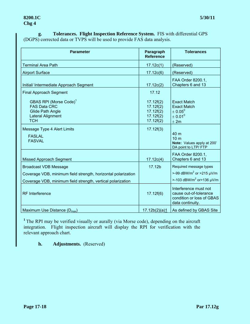
8200.1C 5/30/11 Chg 4
Page 17-18 Par 17.12g
g. Tolerances. Flight Inspection Reference System. FIS with differential GPS (DGPS) corrected data or TVPS will be used to provide FAS data analysis.
Parameter Paragraph Reference
Tolerances
Terminal Area Path 17.12c(1) (Reserved)
Airport Surface 17.12c(6) (Reserved)
Initial/ Intermediate Approach Segment 17.12c(2) FAA Order 8200.1, Chapters 6 and 13
Final Approach Segment GBAS RPI (Morse Code)1 FAS Data CRC Glide Path Angle Lateral Alignment TCH
17.12
17.12f(2) 17.12f(2) 17.12f(2) 17.12f(2) 17.12f(2)
Exact Match Exact Match 0.050
0.010
2m
Message Type 4 Alert Limits
FASLAL FASVAL
17.12f(3) 40 m 10 m Note: Values apply at 200’ DA point to LTP/ FTP
Missed Approach Segment 17.12c(4) FAA Order 8200.1, Chapters 6 and 13
Broadcast VDB Message
Coverage VDB, minimum field strength, horizontal polarization
Coverage VDB, minimum field strength, vertical polarization
17.12b Required message types
>-99 dBW/m2 or >215 μV/m
>-103 dBW/m2 or>136 μV/m
RF Interference 17.12f(6) Interference must not cause out-of-tolerance condition or loss of GBAS data continuity.
Maximum Use Distance (Dmax) 17.12b(2)(a)1 As defined by GBAS Site
1 The RPI may be verified visually or aurally (via Morse code), depending on the aircraft integration. Flight inspection aircraft will display the RPI for verification with the relevant approach chart.
h. Adjustments. (Reserved)

10/01/05 8200.1C
Page 18-1 (and 2)
CHAPTERS 18 - 19
(RESERVED)


10/01/05 8200.1C
Page 20-i (and ii)
CHAPTER 20. FLIGHT INSPECTION OF VFR AERONAUTICAL CHARTS
TABLE OF CONTENTS
Paragraphs Title Pages 20.10 INTRODUCTION.........................................................................................20-1 20.11 PREFLIGHT REQUIREMENTS..................................................................20-1 20.12 DETAILED PROCEDURES ........................................................................20-2 20.13 ANALYSIS AND EVALUATION...............................................................20-2

This Page Intentionally Left Blank

11/01/10 8200.1C Chg 3
Par 20.10 Page 20-1
CHAPTER 20. FLIGHT INSPECTION OF VFR AERONAUTICAL CHARTS
20.10 INTRODUCTION. This chapter describes the procedures used to perform flight inspection of FAA Visual Flight Rules (VFR) Aeronautical Charts. These include Sectional Aeronautical Charts and their associated Terminal Area and VFR Flyway Planning Charts, Helicopter Route Charts, and the Grand Canyon VFR Aeronautical Chart. Data gathered is used to update VFR charts and obstruction data for the FAA Minimum Safe Altitude Warning System (MSAW) program. VFR charts will be evaluated on an on-demand, as needed basis and have no minimum periodic interval.
a. Sectional Aeronautical Chart. Sectional Aeronautical Charts are designed for visual navigation use by slow and medium speed aircraft. The topographic information consists of contour lines, shaded relief, drainage patterns, and an extensive selection of visual checkpoints and landmarks used for flight under VFR. Cultural features include cities and towns, roads, railroads, and other distinct landmarks. The aeronautical information includes visual and radio aids to navigation, airports, controlled airspace, special-use airspace, obstructions,and related data.
b. Terminal Area Chart (TAC). The TAC depicts airspace designated as Class B.
While similar to Sectional Charts, the TAC has more detail on a larger scale chart. The TAC is used by pilots operating to and from airfields underlying or near Class B airspace.
c. Charted VFR Flyway Planning Chart. This chart is printed on the reverse side
of selected TAC Charts. The coverage is the same as the associated TAC. Flyway planning charts depict flight paths and altitudes recommended for use to bypass high traffic areas. Ground references are provided as a guide for visual orientation.
d. Grand Canyon VFR Aeronautical Chart. This chart covers the Grand Canyon
National Park area. It is designed to promote aviation safety, flight free zones, and to facilitate VFR navigation in this popular area. The chart contains aeronautical information for general aviation VFR pilots on one side and commercial VFR air-tour operators on the other side.
e. Helicopter Route Chart. This chart displays aeronautical information useful to
helicopter pilots navigating in areas of high concentrations of helicopter activity. Information depicted includes helicopter routes, heliports with associated frequency and lighting capabilities, NAVAID(s), and obstructions. In addition, pictorial symbols, roads, and easily identified geographical features are portrayed.
20.11 PREFLIGHT REQUIREMENTS. Prior to each VFR Aeronautical Chart flight inspection mission, the inspector(s) will meet with the National Aeronautical Charting Office (NACO) VFR Flight Inspection Program (VFIP) coordinator and cartographers to discuss any issues for the inspection. When VFR Aeronautical Chart flight inspection operations will be conducted in areas affecting air traffic, the inspector must coordinate with Air Traffic Control (ATC).
8200.1C 10/01/05
Page 20-2 Par 20.12
20.12 DETAILED PROCEDURES. Current chart copies are compared with the corresponding geographic areas. The inspector will evaluate and verify topographic and cultural data (roads, railroads, power lines, antennas, urban areas, etc.) depicted on the charts for accuracy and navigational usefulness.
a. Flight Line Track. Flight line tracks will be established to ensure systematic and complete coverage of the entire chart area. Cardinal directions should normally be used unless limited by terrain, localized weather, ATC, or other factors. Flight line spacing may vary to accommodate different levels of visibility and densities of charted features, but should not normally be spaced more than 12 nm.
b. Altitudes. The flight line track must be flown at altitudes that will ensure that the
pilots can clearly observe the relative position of all objects and their characteristic details. The inspection should normally be performed at altitudes between 2,000 to 5,000 feet above ground level (AGL).
c. Weather. VFR Aeronautical Chart flight inspection must be conducted in VFR
conditions.
20.13 ANALYSIS AND EVALUATION. Inspectors mustl record their notes on an annotated VFR chart field sheet. Field sheets are considered source data and must be retained and archived by NACO. The inspector(s) will recommend corrections and changes and resolve questions and discrepancies raised by NACO cartographers that cannot be resolved by source review in the office.

10/01/05 8200.1C
Page 21-1 (and 2)
CHAPTER 21. HELICOPTER
(Reserved)

10/01/05 8200.1C
Page 22-i (and ii)
CHAPTER 22. FLIGHT INSPECTION OF EXPANDED SERVICE VOLUME (ESV) FOR GROUND BASED NAVIGATIONAL AIDS
TABLE OF CONTENTS
Paragraphs Title Pages 22.10 INTRODUCTION.........................................................................................22-1
a. Standard Service Volume (SSV) .......................................................22-1 b. Flight Inspection Standard Service Volume (FISSV) .......................22-1 c. Expanded Service Volume (ESV) .....................................................22-1 d. Operational Service Volume (OSV)..................................................22-1
22.11 DETAILED PROCEDURES ........................................................................22-1
a. Rho-Theta ..........................................................................................22-1 b. Instrument Landing System (ILS) .....................................................22-4 c. Microwave Landing System (MLS)..................................................22-6 d. Nondirectional Beacon (NDB) ..........................................................22-7 e. Distance Measuring Equipment (DME)............................................22-7 f. Area Navigation (RNAV)..................................................................22-7
22.12 EXPANDED SERVICE VOLUME PROCESS ...........................................22-8
a. FMO Approved Limits ......................................................................22-8 b. Clarity of Flight Inspection Results...................................................22-8 c. Expanded Service Volume (ESV) Facilities .....................................22-8
22.13 FLIGHT INSPECTION TOLERANCES......................................................22-9

This Page Intentionally Left Blank

10/01/05 8200.1C
Par 22.10 Page 22-1
CHAPTER 22. FLIGHT INSPECTION OF EXPANDED SERVICE VOLUME (ESV) FOR GROUND BASED NAVIGATIONAL AIDS
22.10 INTRODUCTION. This chapter provides information concerning flight inspection’s role with an Expanded Service Volume (ESV) and the ESV process. Service Volume (SV) is defined as that volume of airspace surrounding a NAVAID within which a signal of usable strength exists and where that signal is not operationally limited by co-channel interference.
NOTE: For VOR/ TACAN/ DME and ILS, the following definitions are used:
a. Standard Service Volume (SSV) - That volume of airspace defined by the national standard.
b. Flight Inspection Standard Service Volume (FISSV) is defined in the appropriate chapter for the specific facility type.
c. Expanded Service Volume (ESV) - An ESV is a volume of airspace, outside of a facility’s Standard Service Volume (SSV), that is approved for operational use by Spectrum Engineering, and where a facility meets the applicable flight inspection requirements. An ESV is validated by flight inspection when requested by the FAA's Air Traffic Service or procedure specialist and approved by frequency management of the Airway Facilities Division.
d. Operational Service Volume (OSV) - The airspace available for operational use. It includes the following:
(1) The SSV excluding any portion of the SSV which has been restricted.
(2) The ESV
22.11 DETAILED PROCEDURES
a. Rho-Theta. ESV(s) are required only when procedural use is predicated on a NAVAID’s performance outside of the SSV, as illustrated in Appendix 3, Figures A3-5A – F. Evaluate ESV(s) on one transmitter only. When required, an ESV may be revalidated by orbital flight at the ESV distance and lowest approved altitude. Lateral limits of the area should encompass allowable radial misalignment or applicable fix displacement area. There is no need to inspect the upper limits of an ESV unless interference is reported or suspected. In most applications, the VOR is the primary facility supporting procedural use (i.e., airways, fixes, intersections). When evaluating facilities supporting procedural uses, record all component signals. If any NAVAID component (i.e., VOR, TAC, or DME) does not meet flight inspection parameter tolerances, document the results as follows.
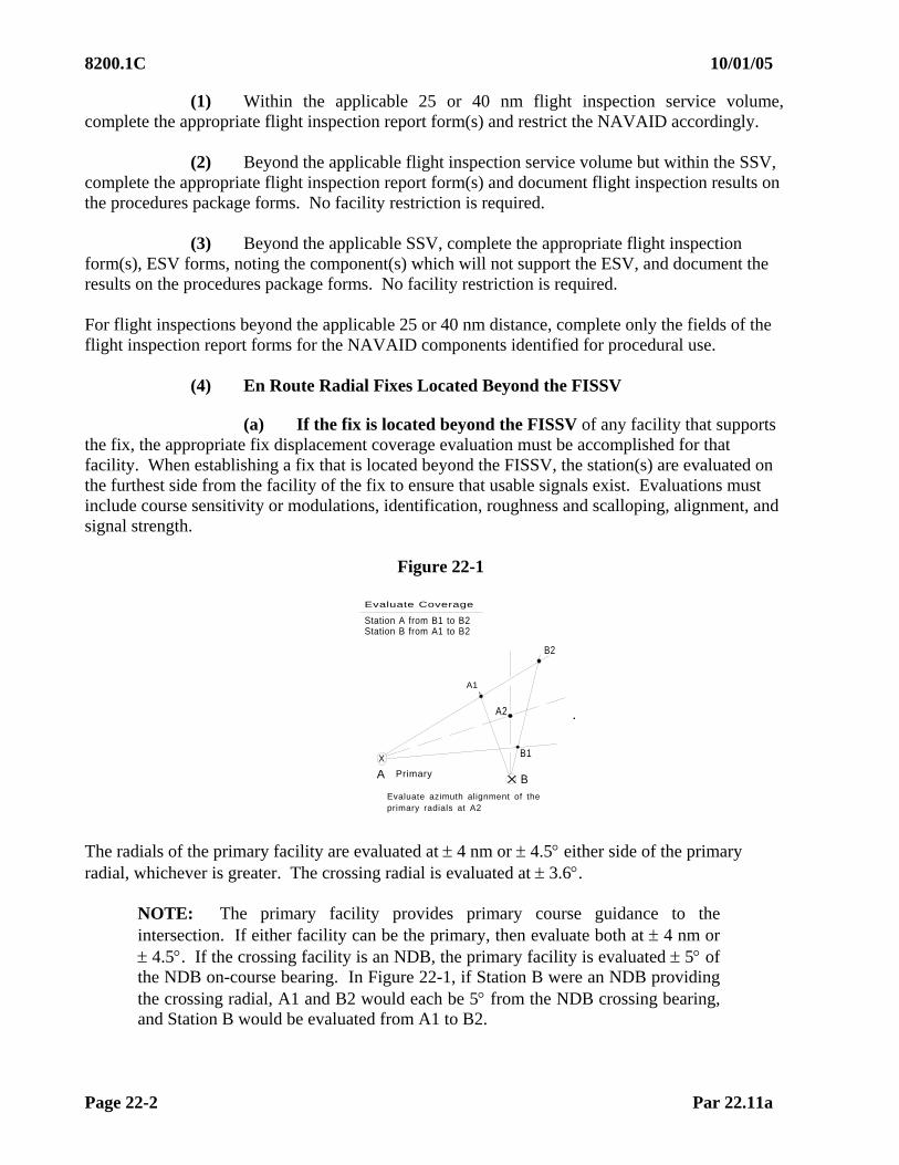
8200.1C 10/01/05
Page 22-2 Par 22.11a
(1) Within the applicable 25 or 40 nm flight inspection service volume, complete the appropriate flight inspection report form(s) and restrict the NAVAID accordingly.
(2) Beyond the applicable flight inspection service volume but within the SSV, complete the appropriate flight inspection report form(s) and document flight inspection results on the procedures package forms. No facility restriction is required.
(3) Beyond the applicable SSV, complete the appropriate flight inspection form(s), ESV forms, noting the component(s) which will not support the ESV, and document the results on the procedures package forms. No facility restriction is required. For flight inspections beyond the applicable 25 or 40 nm distance, complete only the fields of the flight inspection report forms for the NAVAID components identified for procedural use.
(4) En Route Radial Fixes Located Beyond the FISSV
(a) If the fix is located beyond the FISSV of any facility that supports the fix, the appropriate fix displacement coverage evaluation must be accomplished for that facility. When establishing a fix that is located beyond the FISSV, the station(s) are evaluated on the furthest side from the facility of the fix to ensure that usable signals exist. Evaluations must include course sensitivity or modulations, identification, roughness and scalloping, alignment, and signal strength.
Figure 22-1
Evaluate Coverage
Station A from B1 to B2Station B from A1 to B2
B2
A1
A2
A B
X
X
B1
Primary
Evaluate azimuth alignment of theprimary radials at A2
The radials of the primary facility are evaluated at 4 nm or 4.5 either side of the primary radial, whichever is greater. The crossing radial is evaluated at 3.6.
NOTE: The primary facility provides primary course guidance to the intersection. If either facility can be the primary, then evaluate both at 4 nm or 4.5. If the crossing facility is an NDB, the primary facility is evaluated 5 of the NDB on-course bearing. In Figure 22-1, if Station B were an NDB providing the crossing radial, A1 and B2 would each be 5 from the NDB crossing bearing, and Station B would be evaluated from A1 to B2.

10/01/05 8200.1C
Par 22.11a(4)(b) Page 22-3
(b) Coverage Evaluation. The radials of the primary facility are evaluated at 4 nm or 4.5, whichever is greater. At a distance of 50.8 nm, 4 nm equals 4.5 off course. When a fix is beyond 40 nm but within 50.8 nm of the primary facility, the degrees off course that equals 4 nm must be calculated. In Figure 22-2, XXX is the primary facility, and the fix is located 41 nm from the facility. A determination of the degrees off course that equals 4 nm at 41 nm can be made using the chart in Appendix 3, Figure A3-7. For this example, the offset radials equal 5.6 at 41 nm. When the radials of the primary facility are beyond 50.8 nm, the offset radials will be 4.5. An alternative method may be used for the coverage evaluation. Beyond 40 nm but within 50.8 nm, you may fly an arc about the facility at a distance equal to the fix distance plus 4 nm or 4.5, whichever is greater (3.6 for crossing radials). Using the chart in Appendix 3, Figure A3-7, determine the degrees off course equal to 4 nm at the fix distance to determine the appropriate start and stop point of the arc. For the example in Figure 22-2, we will assume both facilities may be primary. Therefore, Facility XXX arc would be flown at 45.17 nm (41 nm plus 4.17 nm which is the distance that equates to 4.5 at 53 nm) from 5.6. The arc about Facility YYY would be flown at 57 nm (53 nm plus 4 nm which is the greater of 4.5 or 4 nm at 41 nm). For radials beyond 50.8 nm, the arc will remain 4.5, but the distance that must be added to the fix distance arc will increase as the distance outbound increases (see Appendix 3, Figure A3-7).
(c) Stand-Alone DME Fixes must be evaluated for coverage 4 nm or 4.50 (whichever is greater) at 5 nm greater than the fix distance.
Figure 22-2
40 nm
41 nm 53 nm
XXX
YYY
4.5 5.6
XXX YYY
4.17nm 4 nm
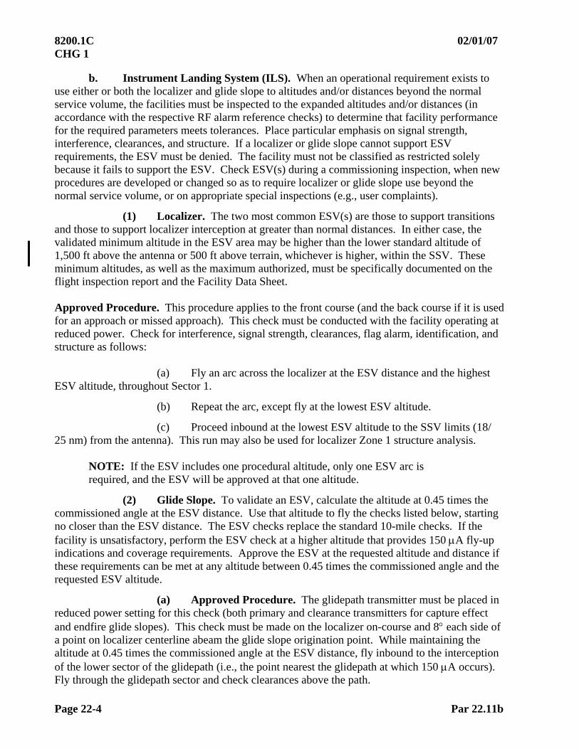
8200.1C 02/01/07 CHG 1
Page 22-4 Par 22.11b
b. Instrument Landing System (ILS). When an operational requirement exists to use either or both the localizer and glide slope to altitudes and/or distances beyond the normal service volume, the facilities must be inspected to the expanded altitudes and/or distances (in accordance with the respective RF alarm reference checks) to determine that facility performance for the required parameters meets tolerances. Place particular emphasis on signal strength, interference, clearances, and structure. If a localizer or glide slope cannot support ESV requirements, the ESV must be denied. The facility must not be classified as restricted solely because it fails to support the ESV. Check ESV(s) during a commissioning inspection, when new procedures are developed or changed so as to require localizer or glide slope use beyond the normal service volume, or on appropriate special inspections (e.g., user complaints).
(1) Localizer. The two most common ESV(s) are those to support transitions and those to support localizer interception at greater than normal distances. In either case, the validated minimum altitude in the ESV area may be higher than the lower standard altitude of 1,500 ft above the antenna or 500 ft above terrain, whichever is higher, within the SSV. These minimum altitudes, as well as the maximum authorized, must be specifically documented on the flight inspection report and the Facility Data Sheet. Approved Procedure. This procedure applies to the front course (and the back course if it is used for an approach or missed approach). This check must be conducted with the facility operating at reduced power. Check for interference, signal strength, clearances, flag alarm, identification, and structure as follows:
(a) Fly an arc across the localizer at the ESV distance and the highest ESV altitude, throughout Sector 1.
(b) Repeat the arc, except fly at the lowest ESV altitude.
(c) Proceed inbound at the lowest ESV altitude to the SSV limits (18/ 25 nm) from the antenna). This run may also be used for localizer Zone 1 structure analysis.
NOTE: If the ESV includes one procedural altitude, only one ESV arc is required, and the ESV will be approved at that one altitude.
(2) Glide Slope. To validate an ESV, calculate the altitude at 0.45 times the commissioned angle at the ESV distance. Use that altitude to fly the checks listed below, starting no closer than the ESV distance. The ESV checks replace the standard 10-mile checks. If the facility is unsatisfactory, perform the ESV check at a higher altitude that provides 150 A fly-up indications and coverage requirements. Approve the ESV at the requested altitude and distance if these requirements can be met at any altitude between 0.45 times the commissioned angle and the requested ESV altitude.
(a) Approved Procedure. The glidepath transmitter must be placed in reduced power setting for this check (both primary and clearance transmitters for capture effect and endfire glide slopes). This check must be made on the localizer on-course and 8 each side of a point on localizer centerline abeam the glide slope origination point. While maintaining the altitude at 0.45 times the commissioned angle at the ESV distance, fly inbound to the interception of the lower sector of the glidepath (i.e., the point nearest the glidepath at which 150 A occurs). Fly through the glidepath sector and check clearances above the path.

11/01/10 8200.1C Chg 3
Par 22.11b(2) Page 22-5
NOTE: Endfire. The endfire glide slope antenna array is orientated toward the runway. The normal fly-up/ fly-down signal ends at approximately 5 on the antenna side of the runway; therefore, you will have only 150 Hz clearance signal at 8 on the antenna side of the runway. The provisions of Paragraph 15.51d will apply to this situation.
(b) Glide slope structure must be analyzed while flying inbound on the glidepath and localizer course from the ESV distance to 10 miles from the glide slope antenna. This evaluation may be conducted in normal or RF reduced power setting.
(3) Reporting Fixes, Transition Areas, SID(s)/ DP(s), STAR(s), and Profile Descents. Refer to Figure 22-3. The localizers, SDF, or LDA may be used to support fixes or departure, en route, and arrival procedures. Transitions may be published through airspace which are beyond the localizer, SDF, or LDA service volume. Under these circumstances, navigation is accomplished using some other facility such as VOR or NDB. If the fix is not contained within the localizer and/or glide slope SSV (see definition in Appendix 1), an ESV must be established to support the procedure.
(a) Required Coverage
1 LOC (A) B1 to B2
2 VOR (B) A1 to B2 (R4.5). Does not need to be checked if within the VOR/ NDB FISSV.
3 VOR (B) A3 to B4.
(b) Transitions. When a transition (or missed approach
routing) is designed to traverse localizer course Sector 3 or airspace which is outside the commissioned service volume, and the transition termination point is not identified with a facility other than the localizer course, check clearance and coverage throughout the entire transition airspace at the minimum authorized altitudes. This will normally be an approach segment from a facility or fix to intercept a localizer final approach. Termination points not requiring clearance validation are: DME fixes on transition radial, waypoint, compass locator, lead radials, fixes made up from other than the localizer, and “radar required” fixes. Examples of a transition requiring clearances would be a radial to the localizer only or a radial to a marker beacon on the localizer course.
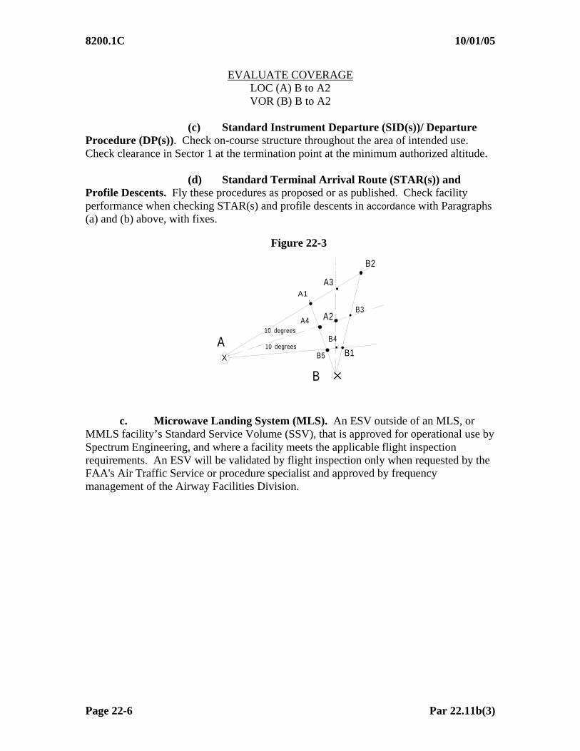
8200.1C 10/01/05
Page 22-6 Par 22.11b(3)
EVALUATE COVERAGE LOC (A) B to A2 VOR (B) B to A2
(c) Standard Instrument Departure (SID(s))/ Departure
Procedure (DP(s)). Check on-course structure throughout the area of intended use. Check clearance in Sector 1 at the termination point at the minimum authorized altitude.
(d) Standard Terminal Arrival Route (STAR(s)) and Profile Descents. Fly these procedures as proposed or as published. Check facility performance when checking STAR(s) and profile descents in accordance with Paragraphs (a) and (b) above, with fixes.
Figure 22-3
B2
A1
A2
X
X
B1
A3
A4
B5
B4
B3
10 degrees
10 degrees
A
B
c. Microwave Landing System (MLS). An ESV outside of an MLS, or
MMLS facility’s Standard Service Volume (SSV), that is approved for operational use by Spectrum Engineering, and where a facility meets the applicable flight inspection requirements. An ESV will be validated by flight inspection only when requested by the FAA's Air Traffic Service or procedure specialist and approved by frequency management of the Airway Facilities Division.

02/01/07 8200.1C CHG 1
Par 22.11d Page 22-7
d. Nondirectional Beacon (NDB):
(1) Evaluate obstructions or hazards for impact on intended procedures and advise the procedure specialist. Evaluate the signal for excessive needle oscillation, weak or garbled ident, and interference as per Paragraph 22.11. Coverage at distances greater than the orbit radius will be certified for specific routes or transitions. The flight inspector must fly intended routes or transitions at the minimum altitudes and maximum distances as depicted in the flight procedure document. For satisfactory performance, the facility must meet the tolerances in Chapter 12, Section 1. If the facility does not support the procedure, the flight inspector must determine the minimum altitudes and maximum distances that meet all the tolerances in Chapter 12, Section 1 and forward this information to the procedure specialist.
(2) Expanded Service Volume (ESV) on commissioned facilities will be established at normal power. At facilities where dual transmitters are installed, evaluate ESV(s) on one transmitter only.
(3) Tolerances. NDB(s)that meet tolerances throughout the area of intended use are classified as UNRESTRICTED. Facilities that do not support routes or transitions outside of coverage as listed in Chapter 12, Section 1 will not be restricted, but use of the facility for that purpose will be denied.
e. Distance Measuring Equipment (DME). Chapter 7, Section 5 provides instructions and performance criteria for certifying standard distance measuring equipment (DME). The flight inspection validation of an ESV for DME can be performed separately but is normally checked in conjunction with the more detailed check of the associated ILS, MLS, VOR, or TACAN facility. When conducting a flight inspection for ESV of DME, independent of an associated facility, check the following:
Accuracy Identification Coverage
f. Area Navigation (RNAV)—Procedural Routes Predicated on DME/
DME Position Estimation. This paragraph addresses ESV guidance for inspection of RNAV procedures requiring a DME/ DME infrastructure. Expanded Service Volume (ESV) requirements: Where the DME infrastructure assessment tool (RNAV-PRO) indicates insufficient DME coverage using standard service volume, the RNAV-PRO can identify proposed ESV(s) for DME facilities that should ensure an acceptable navigational solution.

8200.1C 02/01/07 CHG 1
Page 22-8 Par 22.11f
When ESV documentation is provided in the procedure package, the expected coverage on the ESV form will be compared to the ESV data collected during the flight inspection. The actual facility ESV coverage is presented on the “DME/ DME Leg Summary Report” printed by AFIS at the end of each route inspected. (AFIS Technician User Manual, TI 4040.55, DME/ DME Mode Operations, explains AFIS operation and display). The Leg Summary Report is the actual facility coverage and should be reported on the ESV request form if it is different from the expected coverage on the ESV form. The ESV request form with noted differences is returned to the FICO after the procedure inspection is completed. During the inspection, if a Critical, or ESV designated, DME appears not to be transmitting, verify with Air Traffic or a local Flight Service Station that the facility is in service. If a DME designated Critical is off the air, the inspection must be terminated and resumed after the facility is returned to service. When there are three or less DME(s) and one of the three is out of service, the check should be rescheduled. 22.12 EXPANDED SERVICE VOLUME PROCESS
a. FMO-Approved Limits. When a proponent requests an ESV, the FMO ensures the calculated signal level from the desired (D) facility is sufficient and signal levels from any undesired (U) transmissions are low enough to provide a satisfactory D/ U ratio throughout the area of use. Usually, these values are predicted to be satisfactory at the requested altitude, azimuth, and distance limits. Flight inspections are required to verify satisfactory signal strength and quality (structure, modulation, etc.). In the event that the signal does not meet flight inspection tolerances at the requested and FMO-approved limit, the ESV must be restricted to the limit of satisfactory coverage.
(1) In some cases, the FMO calculations predict satisfactory signal
level and/or frequency protection to some point less than requested. This is indicated on FAA Form 6050-4, Expanded Service Volume Request, by a Part II entry of “Restricted” and definition of the FMO-approved limit. This limit may be due to factors used in the FMO modeling process and not detectable through flight inspection. For example, at the requested distance, the D/ U ratio is unsatisfactory, but flight check only sees a clean signal, meeting flight inspection tolerances. We could then erroneously approve an ESV where there is insufficient frequency protection. In this example, the flight inspection should not extend beyond the Part II Restricted distance or lowest altitude.
(2) Occasionally, frequency protection is not a problem, but desirable
signal strength is calculated to be marginal. The FMO would note in a Part II remark that they approve of an ESV to a given point less than requested, and defer the final approval contingent on a successful flight check at the requested limit. In this case, the flight inspection should be to the requested distance and at the lowest requested altitude.
02/01/07 8200.1C CHG 1
Par 22.12a Page 22-9 (and 10)
(3) It must be understood that flight inspection does not approve any part of an ESV beyond that which is approved by the FMO.
b. Clarity of Flight Inspection Results. Some flight inspection comments in Part III of FAA Form 6050-4 have been misleading. As can be seen from Issue 1, the final flight inspection approval can only be equal to or more restrictive than the FMO-approved limit. If the FMO approves exactly what was originally requested and the signal strength and quality meet flight inspection tolerances to the requested distance and lowest altitude, the flight inspector should check the APPROVED block in Part III. In the Remarks section, define the limits of the ESV by facility component, azimuth/ bearing, distance, and Minimum Reception Altitude (MRA) and Maximum Authorized Altitude (MAA). Any other situation requires a Part III entry of RESTRICTED and a definition of the ESV limits. Facility components, such as VOR and TACAN, which result in different coverage limits, should be defined individually.
c. Expanded Service Volume (ESV) Facilities. When a facility no longer supports an ESV, the facility is not restricted, but a NOTAM must be issued for the instrument flight procedures predicated on that ESV. Coordinate and publish the newly established ESV and instrument flight procedures. 22.13 FLIGHT INSPECTION TOLERANCES. To adequately support a proposed ESV of airspace, facility performance must meet all operational tolerances as described in Chapter 7 (appropriate section) and conform to the process described in Paragraph 22.12 above. Facilities which do not meet tolerances beyond the FISSV must not be restricted; however, procedural use must be denied.

This Page Intentionally Left Blank

10/01/05 8200.1C
Page 23-i (and ii)
CHAPTER 23. RADIO FREQUENCY INTERFERENCE DETECTION
TABLE OF CONTENTS Paragraph Title Pages
23.10 INTRODUCTION .........................................................................................23-1 23.11 PREFLIGHT REQUIREMENTS ..................................................................23-1
a. Facility Maintenance Personnel.........................................................23-1 b. Flight Personnel .................................................................................23-2
23.12 FLIGHT INSPECTION PROCEDURES......................................................23-2 23.13 CHECKLIST..................................................................................................23-2 23.14 DETAILED PROCEDURES.........................................................................23-2
a. Airborne Equipment...........................................................................23-2 b. Search Patterns...................................................................................23-3
23.15 ANALYSIS....................................................................................................23-4
a. Intermittent Interference ....................................................................23-4 b. Interfering Signal ...............................................................................23-4
23.16 TOLERANCES..............................................................................................23-4 23.17 ADJUSTMENTS ...........................................................................................23-4 23.18 RECORDS AND REPORTS.........................................................................23-4

10/01/05 8200.1C
Par 23.10 Page 23-1
CHAPTER 23. RADIO FREQUENCY INTERFERENCE DETECTION 23.10 INTRODUCTION. The radio frequency spectrum, particularly in the VHF communication and navigation bands, is the subject of increasing interference from many sources. This chapter describes the role of flight inspection and presents techniques of flight inspection in the location of Radio Frequency Interference (RFI) to Communications, Navigation, and Surveillance (CNS) systems, including satellite Global Positioning System (GPS).
a. Airborne investigation of RFI is usually the last resort and should not be used until all reasonable ground methods are tried. In general, if an interfering signal can be received on the ground, it can be located through ground investigation. In few instances, usually in remote areas, it may be impractical to use any ground methods. If the source of interference is not near a ground receiver, it may only affect the airborne reception and must be located through use of an aircraft. Although the aircraft has pinpointed some RFI sources, it is generally sufficient to narrow the location down to an area small enough to cover with ground equipment.
b. Types of Interferers. Interference to CNS systems may take several forms, from broadband noise to narrow-band signals. Interference may be constant or intermittent, either predictable or random. Most interference is unintentional, although there have been instances of intentional disruption of air traffic services by individuals or groups for various purposes. Knowing the characteristics of the various types of interference is a key factor in locating their source.
(1) Unintentional interference to CNS systems is usually the result of defective equipment or intermodulation of two or more frequencies. Most cases requiring airborne investigation are due to spurious emissions from defective electric or electronic devices. Many frequencies generated by malfunctioning equipment are not stable and may drift, impacting several victim frequencies.
(2) Intentional interference is usually directed at VHF communications frequencies. Some intentional interference has been disguised as unintentional, but the majority of cases involve voice or music transmitted from a normal VHF transceiver. Some rare cases involve “Phantom Controllers” attempting to misdirect aircraft. As intentional interference to CNS systems is a criminal activity, investigative methods and results should be treated as confidential information to avoid compromising any prosecution of the offenders. 23.11 PREFLIGHT REQUIREMENTS
a. Facility Maintenance Personnel. Tasking for a formal airborne RFI investigation must be initiated by National Operations Control Center (NOCC) Spectrum Engineering Services Liaison through Flight Inspection Central Operations (FICO). Searches for routine, unintentional interference usually require only that the regional Frequency Management Office (FMO) has accomplished a “table top” study of aircraft reports and has determined a likely starting place for the mission. For complex or intentional disruption of service, the NOCC/ FICO/ Regional FMO must ensure ground and air efforts are coordinated. Such coordination should include non-VHF communications and alternate aircraft call signs as necessary for covert operations.
8200.1C 10/01/05
Page 23-2 Par 23.11
b. Flight Personnel. Unless both systems are simultaneously accessible by one person, it may be advantageous to have two technicians, one using the spectrum analyzer, and the other using the Direction Finding (DF) equipment. If the signal is difficult to find, consultation or participation of the local or national spectrum managers should be sought, and these phone contacts kept in the aircraft. 23.12 FLIGHT INSPECTION PROCEDURES. Use the equipment and techniques of Paragraph 23.14 for missions dispatched to search for RFI. Flight inspectors should remain alert to any suspected interference throughout normal flight activities. Any possible interference received must be investigated as thoroughly as possible within the constraints of equipment capabilities and mission limits.
a. If interference is suspected within the Standard or Expanded Service Volume of a facility undergoing flight inspection, attempt to get the facility shut down and verify the presence and characteristics of the interfering signal. If time and circumstances permit, try to identify the source. If it is not readily found, report the findings to the Regional FMO for ground analysis before further airborne attempts.
b. If interference is to a facility or frequency used for normal flight operations, use the applicable techniques from Paragraph 23.14 to analyze the problem. Documenting the signal characteristics at multiple locations along the route of flight will significantly aid the Regional FMO in determining the next step in the process. 23.13 CHECKLIST. There are no specific checklist items for RFI detection and location. 23.14 DETAILED PROCEDURES
a. Airborne Equipment (1) DF Equipment. The DF receiver system produces a strobe indication
giving a Line of Bearing (LOB) from the aircraft to the transmission source. Following the strobe will bring the aircraft to the signal source. Usually, the aircraft is too high on the initial pass over the signal source for its identification. A descending 270 turn to pass over the signal from a different direction may aid in its location.
(2) Spectrum Analyzer. Many interfering signals are not on the affected
frequency but are within the victim receiver’s bandwidth. Tuning the DF receiver to the affected frequency with its bandwidth set too narrow will degrade its effectiveness. Use the spectrum analyzer to find the center frequency and effective bandwidth of any signals that appear close enough to the victim frequency to be the likely interferer.
(3) Flight inspection receivers can be tuned slightly above or below the affected facility frequency to find a peak in signal strength through the flight inspection equipment. This may help find the center frequency of the interference source.
10/01/05 8200.1C
Par 23.14 Page 23-3
(4) Audio Recording. Flight inspection aircraft should be equipped with audio recorders capable of recording from the various communications or navigational radios as selected by the crew. Record the interference whenever practical to assist FMO personnel in characterizing the signals.
(5) Autonomous GPS recording capability is available in some flight inspection aircraft. It continually monitors the GPS signal for any anomalies and stores up to 24 “events” of unsatisfactory GPS data. The airborne technician should monitor this capability and report any new “Events” to the FICO.
b. Search patterns are usually based either on signal strength or a homing receiver. The signal strength methods are less accurate but may be accomplished with more basic equipment.
(1) Hot/ Cold. This method requires the aircraft to go closer or further from the interferer while the signal strength or best signal to noise ratio (SNR) is noted. If the aircraft travels in a straight line, the peak of the signal should be when the transmitter is directly off the aircraft wing. Another track flown 90 from the first will provide another peak. Sequentially flying a “box pattern” of decreasing size will locate the interference.
(2) The second method, particularly useful for finding GPS interference, requires antennas both on the top and bottom of the aircraft feeding separate sensors. With the bottom antenna fed to a receiver or spectrum analyzer and the top to a GPS receiver, the aircraft is banked to both sides. As the GPS interference will be from the ground, banking the aircraft away from the interferer exposes the bottom sensor antenna to more of the interfering signal, decreasing the SNR. It also shades the top antenna from the ground interference and increases the SNR on that receiver. No significant change while banking either left or right indicates the interference is in front or behind the aircraft. Changes in direction can eventually narrow the search area.
(3) Triangulation. A radiation source can be located by using the DF Receiver to get LOB from two or more locations. Using a geodetic calculator program with an “Intersection” function, the coordinates of the receiver(s) and the lines of bearing (True) are input, and the result is the coordinates of the intersection. It is important to use the correct aircraft heading reference (true or magnetic) to correlate with the DF receiver direction reference. The more samples taken with the receiver locations separated by several miles increase the accuracy of the intersection coordinates.
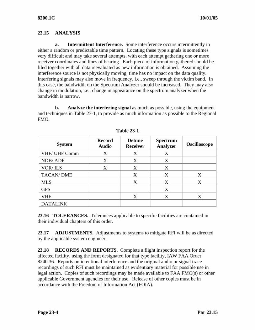
8200.1C 10/01/05
Page 23-4 Par 23.15
23.15 ANALYSIS
a. Intermittent Interference. Some interference occurs intermittently in either a random or predictable time pattern. Locating these type signals is sometimes very difficult and may take several attempts, with each attempt gathering one or more receiver coordinates and lines of bearing. Each piece of information gathered should be filed together with all data reevaluated as new information is obtained. Assuming the interference source is not physically moving, time has no impact on the data quality. Interfering signals may also move in frequency, i.e., sweep through the victim band. In this case, the bandwidth on the Spectrum Analyzer should be increased. They may also change in modulation, i.e., change in appearance on the spectrum analyzer when the bandwidth is narrow.
b. Analyze the interfering signal as much as possible, using the equipment and techniques in Table 23-1, to provide as much information as possible to the Regional FMO.
Table 23-1
System Record Audio
Detune Receiver
Spectrum Analyzer Oscilloscope
VHF/ UHF Comm X X X
NDB/ ADF X X X
VOR/ ILS X X X
TACAN/ DME X X X
MLS X X X
GPS X
VHF X X X
DATALINK 23.16 TOLERANCES. Tolerances applicable to specific facilities are contained in their individual chapters of this order. 23.17 ADJUSTMENTS. Adjustments to systems to mitigate RFI will be as directed by the applicable system engineer. 23.18 RECORDS AND REPORTS. Complete a flight inspection report for the affected facility, using the form designated for that type facility, IAW FAA Order 8240.36. Reports on intentional interference and the original audio or signal trace recordings of such RFI must be maintained as evidentiary material for possible use in legal action. Copies of such recordings may be made available to FAA FMO(s) or other applicable Government agencies for their use. Release of other copies must be in accordance with the Freedom of Information Act (FOIA).
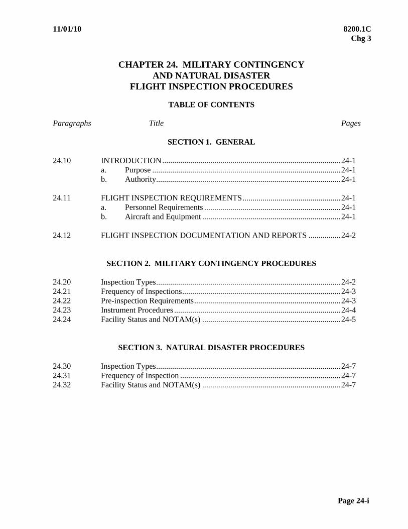
11/01/10 8200.1C Chg 3
Page 24-i
CHAPTER 24. MILITARY CONTINGENCY AND NATURAL DISASTER
FLIGHT INSPECTION PROCEDURES
TABLE OF CONTENTS Paragraphs Title Pages
SECTION 1. GENERAL 24.10 INTRODUCTION.........................................................................................24-1
a. Purpose ..............................................................................................24-1 b. Authority............................................................................................24-1
24.11 FLIGHT INSPECTION REQUIREMENTS.................................................24-1
a. Personnel Requirements ....................................................................24-1 b. Aircraft and Equipment .....................................................................24-1
24.12 FLIGHT INSPECTION DOCUMENTATION AND REPORTS ................24-2
SECTION 2. MILITARY CONTINGENCY PROCEDURES 24.20 Inspection Types............................................................................................24-2 24.21 Frequency of Inspections...............................................................................24-3 24.22 Pre-inspection Requirements.........................................................................24-3 24.23 Instrument Procedures ...................................................................................24-4 24.24 Facility Status and NOTAM(s) .....................................................................24-5
SECTION 3. NATURAL DISASTER PROCEDURES
24.30 Inspection Types............................................................................................24-7 24.31 Frequency of Inspection ................................................................................24-7 24.32 Facility Status and NOTAM(s) .....................................................................24-7
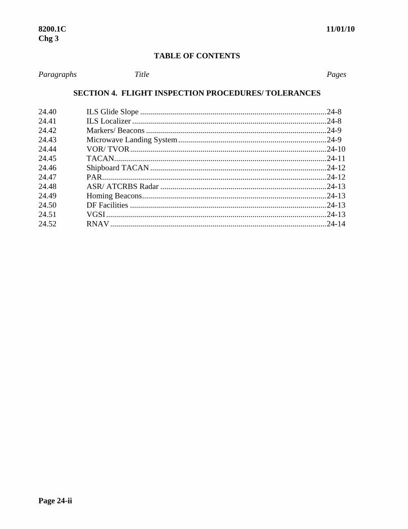
8200.1C 11/01/10 Chg 3
Page 24-ii
TABLE OF CONTENTS Paragraphs Title Pages
SECTION 4. FLIGHT INSPECTION PROCEDURES/ TOLERANCES 24.40 ILS Glide Slope .............................................................................................24-8 24.41 ILS Localizer .................................................................................................24-8 24.42 Markers/ Beacons ..........................................................................................24-9 24.43 Microwave Landing System..........................................................................24-9 24.44 VOR/ TVOR..................................................................................................24-10 24.45 TACAN..........................................................................................................24-11 24.46 Shipboard TACAN ........................................................................................24-12 24.47 PAR................................................................................................................24-12 24.48 ASR/ ATCRBS Radar ...................................................................................24-13 24.49 Homing Beacons............................................................................................24-13 24.50 DF Facilities ..................................................................................................24-13 24.51 VGSI ..............................................................................................................24-13 24.52 RNAV............................................................................................................24-14

10/01/05 8200.1C
Par 24.10 Page 24-1
CHAPTER 24. MILITARY CONTINGENCY AND NATURAL DISASTER
FLIGHT INSPECTION PROCEDURES
SECTION 1. GENERAL
24.10 INTRODUCTION. The potentially catastrophic consequences of a major natural disaster or the need to respond quickly to a military combat operation necessitates advanced planning and definition of operational requirements. The ability to provide sustained flight inspection support for the numerous and diverse requirements which may exist will be predicated upon the use of abbreviated flight inspection procedures. Flight inspection will greatly depend on both air traffic and facility maintenance support preparations.
a. Purpose. The guidance, procedures, and tolerances contained in this chapter describe the minimum facility performance standards when contingency situations require deviation from normal standards. Basic flight inspection requirements and methods of taking measurements apply to the contingency chapter unless specific guidance or tolerances are given. Facilities/ procedures which have been placed in operation using these procedures must be re-inspected to normal standards as soon as circumstances permit.
b. Authority. The authority to implement these provisions may be exercised by either the military or FAA. When military authority determines that an operational situation dictates the application of these procedures and tolerances, the appropriate flight inspection activity and the FAA Aviation System Standards Office (AVN) Manager, Flight Inspection Operations Office must be notified. Application to civil facilities will be determined by appropriate FAA authority, who must notify both Flight Inspection Operations and the appropriate military authority. 24.11 FLIGHT INSPECTION REQUIREMENTS
a. Personnel Requirements. Flight inspection personnel, performing facility/ procedure inspection and certification using the provisions of this chapter, must be authorized and qualified to perform flight inspection duties.
b. Aircraft and Equipment
(1) If necessary, equipment which has exceeded calibration due dates may be used for flight inspection under the following sections. Calibrated equipment must be used when the facility is subsequently inspected using standard procedures.
(2) The use of other than a flight inspection-configured aircraft may be necessary. Reliability of such equipment must be established before use by the flight inspector. Examples of test methods available to verify the accuracy of uncalibrated flight inspection systems or aircraft not equipped with a flight inspection system are:

8200.1C 10/01/05
Page 24-2 Par 24.11
(a) Comparison with a facility verified by maintenance, or another flight inspection aircraft, as operating normally.
(b) Comparison with two or more facilities in operation.
(c) Use of a VOT or similar radiated test signal. 24.12 FLIGHT INSPECTION DOCUMENTATION AND REPORTS
a. All facilities/ procedures inspected using the provisions of this chapter must be assigned a status classification of restricted. All flight inspection records must be retained until the facility/ procedure can be inspected using normal procedures and tolerances.
b. In the event that flight inspection equipment is inoperative or not available, flight inspections will continue to meet operational requirements until replacement or repair is practical. Under these circumstances, the flight inspection crew is responsible for documenting all of the applicable data displayed by instrumentation at their duty positions. All such manually-acquired data must be identified in the remarks section of the flight inspection report. The facility/ procedure must be reflown with operational flight inspection equipment when conditions permit.
c. Completion and distribution of flight inspection reports are secondary to the accomplishment of flight inspection. At the conclusion of the inspection, the flight inspector must pass the facility status to the air traffic control watch supervisor. This will suffice as the official report until the written report has been completed and distributed.
d. The flight inspector must ensure that flight inspection reports are completed and submitted for processing. Each parameter specified in this section’s flight inspection procedures checklists must be reported. Flight inspection reports may be handwritten using reproducible ink.
e. Records and reports must reflect that the inspection was accomplished using MILITARY CONTINGENCY FLIGHT INSPECTION PROCEDURES or NATURAL DISASTER FLIGHT INSPECTION PROCEDURES, as appropriate. If only the final and missed approach segments were inspected, annotate the facility is in operation for “approach use only.”
SECTION 2. MILITARY CONTINGENCY PROCEDURES
24.20 INSPECTION TYPES
a. Only special and commissioning type flight inspections will be conducted under the procedures contained in this section. A commissioning flight inspection under this section will provide a limited-use facility where only the desired instrument procedures are supported.
b. After-accident flight inspection must follow normal procedures to the maximum
extent possible.

11/01/10 8200.1C Chg 3
Par 24.21 Page 24-3
24.21 FREQUENCY OF INSPECTIONS
a. Non-precision. All non-precision facilities will be re-commissioned using this section or the applicable chapter of this manual, as conditions warrant, within the period of 180 to 360 days after the previous contingency inspection. If the facility goes more than 360 days without being re-commissioned, and the controlling military commander wishes to continue to use the facility, it will convert to a “For Military Use Only” facility as described in Paragraph 24.24d, and the appropriate NOTAM(s) must be issued.
b. Precision. All precision facilities will be re-commissioned using this section or the applicable chapter of this manual, as conditions warrant, within the period of 90 to 180 days after the initial contingency inspection. If the precision facility was re-commissioned using contingency procedures with the 90 to 180 period, the facility periodicity would transition to 180 days, then 270 days. Due date window for subsequent inspections is 60 days. If after the initial inspection the facility goes more than 180 days without being re-commissioned or due date windows for subsequent inspections are not met, and the controlling military commander wishes to continue to use the facility, it will convert to a “For Military Use Only” facility as described in Paragraph 24.24d, and the appropriate NOTAM(s) must be issued.
c. RNAV SIAP(s). When conducting a special inspection to satisfy periodic inspection requirements for RNAV SIAP(s), flying the actual procedure is not required. However, an obstacle assessment must be conducted through the final and missed approach segments. Follow the guidance in Chapter 6. The requirement to conduct obstacle assessment may be evaluated independent of a SIAP inspection.
24.22 PRE-INSPECTION REQUIREMENTS. The combatant commander being supported, or appropriate designee, is required to supply the flight inspection crew with the necessary support to accomplish the mission. This may include, but is not limited to, crew and airplane bed down, current intelligence, threat assessment, theater Special Instructions (SPINs), entry in the Air Tasking Order (ATO), and, if deemed necessary, escort aircraft. The flight inspection crew must provide proper documentation to gain access to any classified information.
a. Prior to arriving on location, the flight inspector mission commander or the controlling military office must contact the airfield operations commander and the navigation aid maintenance supervisor in order to coordinate the following items:
(1) Arrival time
(2) Operational requirements as defined by the airfield operations commander.
(3) Airspace requirements for conducting the flight inspection profile.
(4) Anticipated support such as refueling, ground transportation for a theodolite operator, etc.
b. The airfield operations commander must accomplish the following prior to arrival of the flight inspection aircraft.
(1) Make final determination regarding operational requirements for the facilities and SIAP(s) requiring flight inspection, and be prepared to brief changes on initial contact.

8200.1C 11/01/10 Chg 3
Page 24-4 Par 24.22
(2) Coordinate airspace requirements and obtain necessary clearances from appropriate airspace control authorities for conducting the inspection.
(3) If required, designate and brief an air traffic controller to work the flight inspection aircraft.
(4) Provide current Facility Data Sheet (FAA Form 8240-22) for each facility to be inspected.
c. The navigation aid maintenance supervisor must:
(1) Ensure adequate radio communications are available and operational.
(2) Assign qualified maintenance personnel to support the flight inspection of the equipment being inspected.
(3) Assist the airfield operations commander in completing FAA Form 8240-22 (Facility Data Sheet) for each facility to be inspected.
(4) Arrange for ground transportation for the theodolite operator if necessary. 24.23 INSTRUMENT PROCEDURES
a. Approach Procedure
(1) The minimum flight inspection required to certify SIAP(s) predicted on ground-based facilities is the inspection of the final approach and missed approach segments. Area navigation (RNAV) procedures require the inspection of the intermediate, final, and missed approach segments. A night inspection is not required for an airfield/ runway conducting military only operations.
(2) If an approach must be established, the flight inspector may be responsible for establishing final and missed approach segments. Both segments of the procedure must be flown and recorded to establish and document flyability, accuracy, reliability, and obstacle clearance. The flight inspector must record the SIAP on the flight inspection report and provide the air traffic control watch supervisor with adequate detail for issuance of the NOTAM.
(3) In all cases, the flight inspector must determine, through visual evaluation, that the final and missed approach segments provide adequate terrain and obstacle clearance.
(4) If a circling maneuver is desired, the flight inspector must comply with Paragraph 6.14. Otherwise, a NOTAM stating that circling is not authorized must be issued.
b. En Route and Transition Coverage. If there is a need for facility coverage to
provide en route and environment guidance, air traffic control may use aircraft of opportunity to fly the transition procedure. Pilot reports of satisfactory cockpit instrument performance and controller evaluation of radar target strengths are sufficient for air traffic control to determine usability.
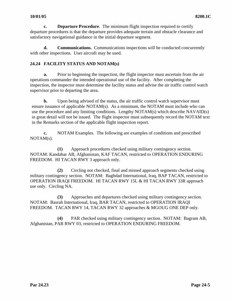
10/01/05 8200.1C
Par 24.23 Page 24-5
c. Departure Procedure. The minimum flight inspection required to certify departure procedures is that the departure provides adequate terrain and obstacle clearance and satisfactory navigational guidance in the initial departure segment.
d. Communications. Communications inspections will be conducted concurrently with other inspections. User aircraft may be used. 24.24 FACILITY STATUS AND NOTAM(s)
a. Prior to beginning the inspection, the flight inspector must ascertain from the air operations commander the intended operational use of the facility. After completing the inspection, the inspector must determine the facility status and advise the air traffic control watch supervisor prior to departing the area.
b. Upon being advised of the status, the air traffic control watch supervisor must ensure issuance of applicable NOTAM(s). As a minimum, the NOTAM must include who can use the procedure and any limiting conditions. Lengthy NOTAM(s) which describe NAVAID(s) in great detail will not be issued. The flight inspector must subsequently record the NOTAM text in the Remarks section of the applicable flight inspection report.
c. NOTAM Examples. The following are examples of conditions and prescribed NOTAM(s).
(1) Approach procedures checked using military contingency section. NOTAM: Kandahar AB, Afghanistan, KAF TACAN, restricted to OPERATION ENDURING FREEDOM. HI TACAN RWY 3 approach only.
(2) Circling not checked, final and missed approach segments checked using military contingency section. NOTAM: Baghdad International, Iraq, BAP TACAN, restricted to OPERATION IRAQI FREEDOM. HI TACAN RWY 15L & HI TACAN RWY 33R approach use only. Circling NA.
(3) Approaches and departures checked using military contingency section. NOTAM: Basrah International, Iraq, BAR TACAN, restricted to OPERATION IRAQI FREEDOM. TACAN RWY 14, TACAN RWY 32 approaches & MGOUG ONE DEP only.
(4) PAR checked using military contingency section. NOTAM: Bagram AB, Afghanistan, PAR RWY 03, restricted to OPERATION ENDURING FREEDOM.
8200.1C 11/01/10 Chg 3
Page 24-6 Par 24.24
d. The flight inspector has the authority and responsibility for determining that a NAVAID can safely and adequately support the operations intended under contingency conditions. However, military commanders have final authority and responsibility for operation of military facilities which are not part of the common system, and may elect to use those facilities FOR MILITARY MISSIONS. Additionally, the military may elect to use a military or civil NAVAID, which is part of the common system, even though that NAVAID is considered unusable by the flight inspector. In all such cases, the military commander that controls the NAVAID is responsible for issuing the appropriate NOTAM advising that the NAVAID is in operation "For Military Use Only" and stating which aircraft are authorized to use it.
In that flight inspection supports the ground maintenance organization or host nation aviation authority, care should be taken not to mistake the facility status assigned by a flight inspection as the last and only step required for authorizing a facility for use. There is potential for confusion, especially when ownership of a facility and maintenance responsibility is transferred to the host nation in which it is located, and flight inspection services are still being provided by another country or military organization.
11/01/10 8200.1C Chg 3
Par 24.30 Page 24-7
SECTION 3. NATURAL DISASTER PROCEDURES 24.30 INSPECTION TYPES. Only special type flight inspections will be conducted under the procedures contained in this section. 24.31 FREQUENCY OF INSPECTIONS
a. Non-precision. All non-precision facilities will be re-inspected using this section or the applicable chapter of this manual, as conditions warrant, within the period of 180 to 360 days after the previous contingency inspection. If the facility goes more than 360 days without being re-inspected, the FICO must initiate NOTAM action to remove them from service.
b. Precision. All precision facilities will be re-inspected using this section or the applicable chapter of this manual, as conditions warrant, within the period of 90 to 180 days after the initial contingency inspection. If the precision facility was re-inspected using contingency procedures with the 90 to 180 period, the facility periodicity would transition to 180 days, then 270 days. Due date window for subsequent inspections is 60 days. If after the initial inspection the facility goes more than 180 days without being re-inspected or due date windows for subsequent inspections are not met, the FICO must initiate NOTAM action to remove them from service. 24.32 FACILITY STATUS AND NOTAM(s). Prior to beginning the inspection, the flight inspector must ascertain from air traffic control the intended operational use of the facility. After completing the inspection, the inspector must determine the facility status for emergency use and advise the air traffic control watch supervisor prior to departing the area. NOTAM(s)/ Restrictions must be issued for airspace within the Flight Inspection SSV not checked, i.e., “PWA VOR: Approach Use Only”, or “IRW VORTAC Azimuth and DME unusable 031° cw 009°; 010° cw 030° beyond 15 nm”. Upon being advised of the status, the air traffic control watch supervisor must ensure issuance of applicable NOTAM(s). Unusable SIAP(s), or portions thereof, must be included in the NOTAM (e.g., ELP VOR and TACAN: VOR SIAP Runway 26L unusable TACAN SIAP Runway 26L unusable). The NOTAM for a civil facility must be issued as a NOTAM D to ensure that information is made available using the most expeditious method. Lengthy NOTAM(s) which describe NAVAID(s) in great detail will not be issued. The flight inspector must subsequently record the NOTAM text in the Remarks section of the applicable flight inspection report.
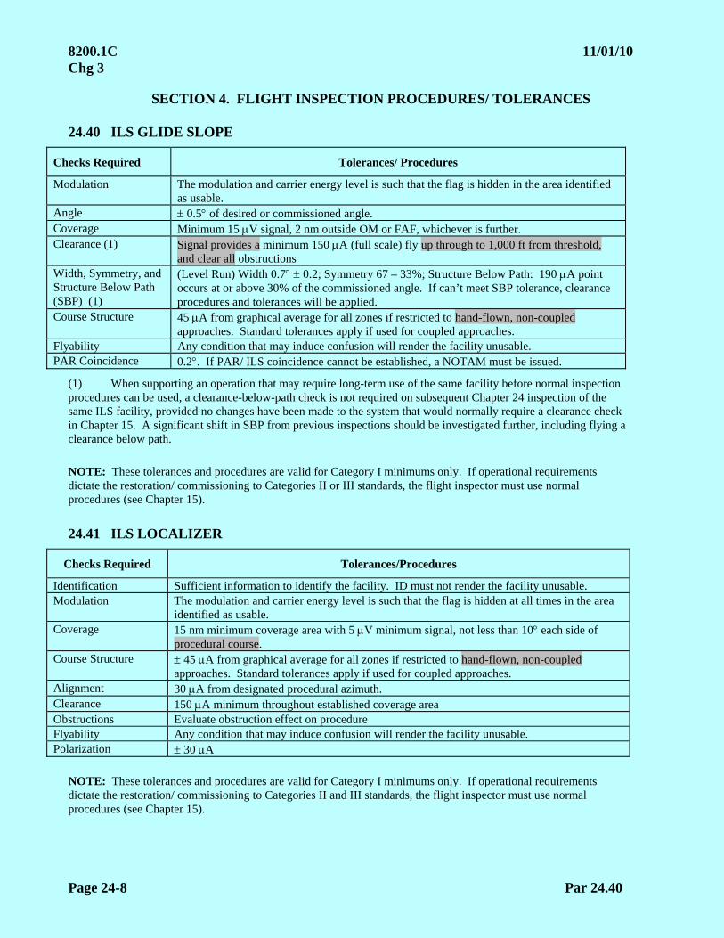
8200.1C 11/01/10 Chg 3
Page 24-8 Par 24.40
SECTION 4. FLIGHT INSPECTION PROCEDURES/ TOLERANCES 24.40 ILS GLIDE SLOPE
Checks Required Tolerances/ Procedures
Modulation The modulation and carrier energy level is such that the flag is hidden in the area identified as usable.
Angle 0.5 of desired or commissioned angle. Coverage Minimum 15 V signal, 2 nm outside OM or FAF, whichever is further. Clearance (1) Signal provides a minimum 150 A (full scale) fly up through to 1,000 ft from threshold,
and clear all obstructions Width, Symmetry, and Structure Below Path (SBP) (1)
(Level Run) Width 0.7 0.2; Symmetry 67 – 33%; Structure Below Path: 190 A point occurs at or above 30% of the commissioned angle. If can’t meet SBP tolerance, clearance procedures and tolerances will be applied.
Course Structure 45 A from graphical average for all zones if restricted to hand-flown, non-coupled approaches. Standard tolerances apply if used for coupled approaches.
Flyability Any condition that may induce confusion will render the facility unusable. PAR Coincidence 0.2. If PAR/ ILS coincidence cannot be established, a NOTAM must be issued.
(1) When supporting an operation that may require long-term use of the same facility before normal inspection procedures can be used, a clearance-below-path check is not required on subsequent Chapter 24 inspection of the same ILS facility, provided no changes have been made to the system that would normally require a clearance check in Chapter 15. A significant shift in SBP from previous inspections should be investigated further, including flying a clearance below path. NOTE: These tolerances and procedures are valid for Category I minimums only. If operational requirements dictate the restoration/ commissioning to Categories II or III standards, the flight inspector must use normal procedures (see Chapter 15). 24.41 ILS LOCALIZER
Checks Required Tolerances/Procedures
Identification Sufficient information to identify the facility. ID must not render the facility unusable. Modulation The modulation and carrier energy level is such that the flag is hidden at all times in the area
identified as usable. Coverage 15 nm minimum coverage area with 5 V minimum signal, not less than 10 each side of
procedural course. Course Structure 45 A from graphical average for all zones if restricted to hand-flown, non-coupled
approaches. Standard tolerances apply if used for coupled approaches. Alignment 30 A from designated procedural azimuth. Clearance 150 A minimum throughout established coverage area Obstructions Evaluate obstruction effect on procedure Flyability Any condition that may induce confusion will render the facility unusable. Polarization 30 A
NOTE: These tolerances and procedures are valid for Category I minimums only. If operational requirements dictate the restoration/ commissioning to Categories II and III standards, the flight inspector must use normal procedures (see Chapter 15).
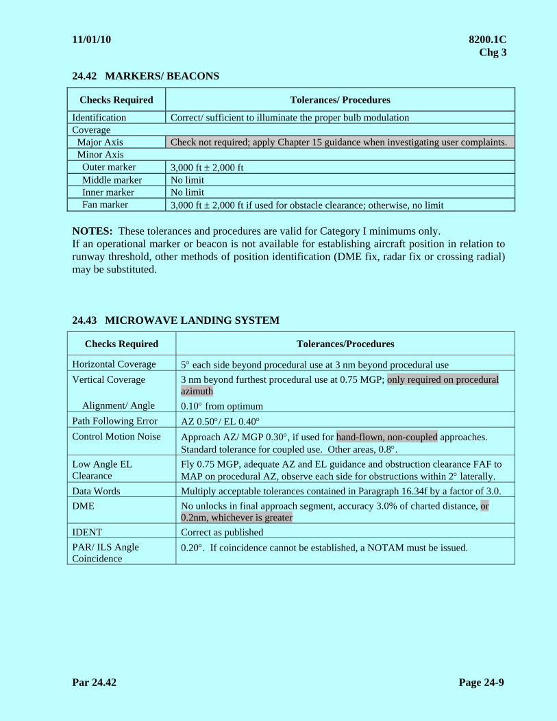
11/01/10 8200.1C Chg 3
Par 24.42 Page 24-9
24.42 MARKERS/ BEACONS
Checks Required Tolerances/ Procedures
Identification Correct/ sufficient to illuminate the proper bulb modulation Coverage Major Axis Check not required; apply Chapter 15 guidance when investigating user complaints. Minor Axis Outer marker 3,000 ft 2,000 ft Middle marker No limit Inner marker No limit Fan marker 3,000 ft 2,000 ft if used for obstacle clearance; otherwise, no limit NOTES: These tolerances and procedures are valid for Category I minimums only. If an operational marker or beacon is not available for establishing aircraft position in relation to runway threshold, other methods of position identification (DME fix, radar fix or crossing radial) may be substituted. 24.43 MICROWAVE LANDING SYSTEM
Checks Required Tolerances/Procedures
Horizontal Coverage 5 each side beyond procedural use at 3 nm beyond procedural use
Vertical Coverage 3 nm beyond furthest procedural use at 0.75 MGP; only required on procedural azimuth
Alignment/ Angle 0.10 from optimum
Path Following Error AZ 0.50/ EL 0.40 Control Motion Noise Approach AZ/ MGP 0.30, if used for hand-flown, non-coupled approaches.
Standard tolerance for coupled use. Other areas, 0.8. Low Angle EL Clearance
Fly 0.75 MGP, adequate AZ and EL guidance and obstruction clearance FAF to MAP on procedural AZ, observe each side for obstructions within 2 laterally.
Data Words Multiply acceptable tolerances contained in Paragraph 16.34f by a factor of 3.0.
DME No unlocks in final approach segment, accuracy 3.0% of charted distance, or 0.2nm, whichever is greater
IDENT Correct as published
PAR/ ILS Angle Coincidence
0.20. If coincidence cannot be established, a NOTAM must be issued.

8200.1C 11/01/10 Chg 3
Page 24-10 Par 24.44
24.44 VOR
Checks Required Tolerances/Procedures
Identification Sufficient information to identify the facility. ID must not render any parameter unusable.
Sensing and Rotation Correct Polarization 4.0o
Modulation AM: 25 to 35% FM Deviation Ratio: 14.8 - 17.2 9960: 20 - 35% with voice 20 - 55% without voice Modulation exceeding the listed tolerances is acceptable, using the following criteria: .05 nm in any 1.0 nm segment from FAF to MAP 0.25 nm in any 5 nm segment from sea level up to 10,000 ft MSL 0.5 nm in any 10 nm segment from 10,001 to 20,000 ft MSL 1.0 nm in any 20 nm segment above 20,000 ft MSL
Approach Alignment within + 2.5. Structure not to exceed 6.0. Inspect from FAF to MAP. Missed Approach Meets flyability constraints until clear of obstructions and course is established. En Route Alignment within 4.0. Structure not to exceed 6.0. Monitors To be set and checked by maintenance. Flight inspection will verify when practical. Standby Equipment Will be checked by transmitter change on approach and en route radials. Coverage Sufficient to support requirements. Flyability Any condition that may induce confusion will render the procedure or facility
unusable. Voice Voice must not render any parameter unusable. NOTES:
Check crosspointer, FLAG, and AGC when arriving and departing VOR coverage area, and during all other phases of the inspection when practical.
Alignment orbit, coverage orbit, transmitter differential, and inspection of radials 5 each side of final approach radial are not required.
Final approach segments may be inspected inbound or outbound.

11/01/10 8200.1C Chg 3
Par 24.45 Page 24-11
24.45 TACAN
Checks Required Tolerances/ Procedures
Identification Sufficient information to identify the facility. ID must not render any parameter unusable.
Sensing and Rotation Correct Polarization 4.0 Distance Accuracy 3% of charted distance or 0.2 nm, whichever is greater Approach Alignment within 2.5. Structure not to exceed 6.0. ¼ nm aggregate azimuth,
DME unlock, or out-of-tolerance structure permitted. Inspect from FAF to MAP. Missed Approach Meets flyability constraints until clear of obstructions and course is established. En Route Alignment within 4.0o. Structure not to exceed 6.0. 1.0 nm aggregate azimuth,
DME unlock, or out-of-tolerance structure permitted in any 5 nm of radial flight. Monitors To be set and checked by maintenance. Flight inspection will verify when practical. Standby Equipment Will be checked by transponder change on approach and en route radials Coverage Sufficient to support requirements. Flyability Any condition that may induce confusion will render that procedure or facility
unusable.
NOTES:
Check crosspointer, FLAG, and AGC when arriving and departing TACAN coverage area, and during all other phases of the inspection when practical.
Alignment orbit, coverage orbit, transmitter differential, and null checks are not required.
Final approach segments may be inspected inbound or outbound.

8200.1C 11/01/10 Chg 3
Page 24-12 Par 24.46
24.46 SHIPBOARD TACAN
Checks Required Tolerances/Procedures
Identification Sufficient information to identify the facility. ID must not render any parameter unusable.
Sensing and Rotation Correct
Polarization 4.0 Distance Accuracy 3% or 1.0 nm, whichever is greater Approach Alignment within 2.5o. Structure not to exceed 6.0o. ¼ nm aggregate azimuth,
DME unlock, or out-of-tolerance structure permitted. Fly the radial from a minimum of 7 nm and 700 ft MSL to pass over the ship at 300 ft MSL.
En Route Alignment within 4.0o. Structure not to exceed 6.0o. 1.0 nm aggregate azimuth, DME unlock, or out-of-tolerance structure permitted in any 5 nm of radial flight.
Equipment Stability Stability will be checked during radial inspection by requesting the ship to turn left 15o and then right 15o. Advise the ship's personnel of any change in azimuth or alignment during the turns.
Standby Equipment Will be checked by transponder change on approach and en route radials Flyability Any condition that may induce confusion will render that procedure or facility
unusable 24.47 PAR
Checks Required Tolerances/Procedures
Course Alignment Sufficient to guide an aircraft down the runway centerline extended, within 50' of runway centerline at threshold. Helicopter-only approaches require delivery to within 50' either side of desired touchdown point.
Glidepath Alignment 0.5 of the commissioned angle. If PAR/ ILS coincidence ( 0.2) cannot be established, a NOTAM must be issued.
Lower Safe Limit Clear all obstacles to threshold Coverage Sufficient to meet operational requirements. Range Accuracy 5% of true range and sufficient to determine when aircraft is over threshold Flyability Any condition that may induce confusion will render the facility unusable.
NOTE: Aircraft with altimeters calibrated according to FAR 43, Appendix E, and FAR 91.180, or military specifications, may be used for PAR flight checks.

11/01/10 8200.1C Chg 3
Par 24.48 Page 24-13
24.48 ASR/ ATCRBS RADAR
Checks Required Tolerances/ Procedures
Azimuth Accuracy En route--within 5
Approaches: 1. Straight-in within 500' of the edges of the runway at the MAP. 2. Approach to airport/ circling within a radius of the MAP which is 5% of the aircraft-to-antenna distance or 1,000', whichever is greater.
Range Accuracy Approach and en route within 5% of fix-to-station distance or 500', whichever is greater.
Coverage Sufficient to support requirement. Targets of opportunity may be used by air traffic personnel. Standard vertical and horizontal coverage profiles not required.
24.49 HOMING BEACONS
Checks Required Tolerances/Procedures
Identification Sufficient information to identify the facility. Coverage En route-- 15 needle swing. Approach-- 10 needle swing. Sufficient signal to
support required use. Station Passage Approximately over the station at all altitudes Flyability Any condition that may induce confusion will render the procedure or use unusable. 24.50 DF FACILITIES
Checks Required Tolerances/ Procedures
Same as standard See Chapter 8 24.51 VGSI
Checks Required Tolerances/ Procedures
Glidepath Alignment Actual angle need not be determined but must be safe and adequate to support requirements as determined by flight inspector. If angle is measured, 0.5 of the commissioned angle. Angle must be suitably coincident with PAR/ MLS/ ILS to preclude pilot confusion or must be NOTAMed as non-coincidental.
Lower Safe Limit Clear all obstacles to threshold. Coverage Sufficient to meet operational requirements/ Transitions All light boxes must transition from red to white in the correct sequence. Flyability Any condition that may induce confusion will render the facility unusable.
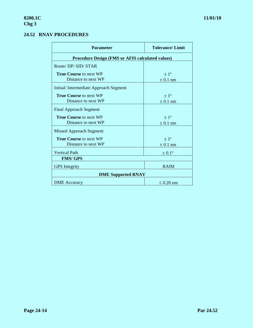
8200.1C 11/01/10 Chg 3
Page 24-14 Par 24.52
24.52 RNAV PROCEDURES
Parameter Tolerance/ Limit
Procedure Design (FMS or AFIS calculated values)
Route/ DP/ SID/ STAR
True Course to next WP Distance to next WP
1 0.1 nm
Initial/ Intermediate Approach Segment
True Course to next WP Distance to next WP
1 0.1 nm
Final Approach Segment
True Course to next WP Distance to next WP
1 0.1 nm
Missed Approach Segment
True Course to next WP Distance to next WP
1 0.1 nm
Vertical Path 0.1 FMS/ GPS
GPS Integrity RAIM
DME Supported RNAV
DME Accuracy 0.20 nm
5/30/11 8200.1C Chg 4 Appendix 1
Page A1-1
APPENDIX 1. SUPPLEMENTAL INFORMATION
SECTION 1. GLOSSARY Definitions and Symbols. The use of italics within a definition denotes another definition contained within this section.
Actual Glidepath Alignment or Actual Glidepath Angle. The straight line arithmetic mean of all deviations around the on-path position derived in ILS Zone 2.
Actual Course (Alignment). The straight line arithmetic mean of all deviations around the on-course position derived from the area in which alignment was taken.
Actual Navigation Performance (ANP). Sometimes called Estimated Position Error (EPE) or “Q” factor, is an onboard computation of the estimated 95% Navigation System Error using knowledge of the real world navigation environment, i.e., number of satellites tracked, number/ geometry of ground facilities, and statistical error models of the various navigation sources. ANP is continuously compared to RNP, and the crew is alerted if ANP exceeds RNP.
AFIS Corrected Error Trace. A graphical presentation of deviation about the mean of all points measured in ILS Zone 2 for glidepaths and Zones 2 and 3 for localizers.
Automatic Gain Control (AGC). A process of electronically regulating the gain in the amplification stages of a receiver so that the output signal tends to remain constant though the incoming signal may vary in strength.
AGC Current or Voltage. A current or voltage responding to the action of the AGC circuit that may be interpreted in terms of signal intensity.
Air Traffic Control Radar Beacon System (ATCRBS). The general term of the ultimate in functional capability afforded by several automation systems. Each differs in functional capabilities and equipment. ARTS IA, ARTS II, ARTS III, and ARTS IIIA (see AIM).
Airway/ Federal Airway. A control area or portion thereof established in the form of a corridor, the centerline of which is defined by navigational aids (refer to FAR Part 71, AIM).
Alert. An indication provided to other aircraft systems or annunciation to the pilot to identify an operating parameter of a navigation system is out of tolerance.
Alert Limit. For a given parameter measurement, the error tolerance not to be exceeded without issuing an alert.
Alignment. Coincidence of a positional or directional element with its nominal reference.
Alignment, Azimuth. The azimuth or actual magnetic bearing of a course.
Alignment, Elevation. The actual angle above a horizontal plan originating at a specific point of a course used for altitude guidance.
Alignment Error. The angular or linear displacement of a positional or directional element from its normal reference.

8200.1C Chg 4 5/30/11 Appendix 1
Page A1-2
Alignment Error, Azimuth. The difference in degrees between the position of a selected course and the correct magnetic azimuth for this course.
NOTE: The error is positive when the course is clockwise from the correct azimuth.
Alignment Error, Elevation. The difference in degrees between the measured angle of the course and the correct angle for the course.
NOTE: The error is positive when the course is above the correct angle.
ALTITUDES:
a. Absolute Altitude. The altitude of the aircraft above the surface it is flying (AC 00-6A). It may be read on a radio/ radar altimeter.
b. Calibrated Altitude. Indicated altitude corrected for static pressure error, installation error, and instrument error.
c. Indicated Altitude. The altitude as shown by an altimeter on a pressure or barometric altimeter. It is altitude as shown uncorrected for instrument error and uncompensated for variation from standard atmospheric conditions (AIM).
d. Pressure Altitude. Altitude read on the altimeter when the instrument is adjusted to indicate height above the standard datum plane (29.92" Hg.)(AC 61-27 latest revision).
e. True Altitude. The calibrated altitude corrected for nonstandard atmospheric conditions. It is the actual height above mean sea level (AC 61-27).
Ampere. A unit of electric current such as would be given with an electromotive force of one volt through a wire having a resistance of one OHM. See Symbols. See Crosspointer.
Amplitude (Peak). The maximum instantaneous value of a varying voltage or current measured as either a positive or negative value.
Anomalous Propagation. Weather phenomena resulting in a layer in the atmosphere capable of reflecting or refracting electromagnetic waves either toward or away from the surface of the earth.
Angle Voltage. The alignment points of the azimuth and elevation electronic cursors are expressed in angle voltage or dial divisions.
Antenna. A device used to radiate or receive electromagnetic signals.
Antenna Reflector. That portion of a directional array, frequently indirectly excited, which reduces the field intensity behind the array and increases it in the forward direction.
Approach Azimuth. Equipment which provides lateral guidance to aircraft in the approach and runway regions. This equipment may radiate the Approach Azimuth function or the High Rate Approach Azimuth function along with appropriate basic and auxiliary data.
Approach Elevation. The equipment which provides vertical guidance in the approach region. This equipment radiates the Approach Elevation function.
Approach Reference Datum (ARD). A point at a specified height located vertically above the intersection of the runway centerline and the threshold.
5/30/11 8200.1C Chg 4 Appendix 1
Page A1-3
Approach with Vertical Guidance (APV). RNAV procedures with vertical guidance are termed “APV” (approach with Vertical Guidance). APV is a classification of approach capability between Non-Precision and Precision. APV landing minimums are based on the performance criteria and technology related to the Navigation System Error (NSE), Flight Technical Error, and Total System Error (TSE).
Area Navigation (RNAV). A method of navigation that permits aircraft operations on any desired course within the coverage of station referenced navigation signals or within the limits of self-contained system capability (AIM).
Area VOT. A facility designed for use on the ground or in the air. It may be located to provide the test signal to one or more airports.
8200.1C Chg 4 5/30/11 Appendix 1
Page A1-4
ARINC Specification 424. ARINC Specification 424 is a standard by which a navigation is created to interface with an airborne navigation computer (i.e., FMS, GPS receiver, etc.) The navigation database will provide paths and termination points for the navigation computer to follow. ARINC 424 defines 23 leg path and terminators. A limited number of the leg types can be used to define RNAV procedures. The leg types used to define RNP RNAV procedures are further limited in order to provide repeatable aircraft ground tracks.
Attenuation. The reduction in the strength of a signal, expressed in decibels (dB).
Auxiliary Data. Data, transmitted in addition to basic data, that provide Facilities Maintenance equipment siting information for use in refining airborne position calculations and other supplementary information.
Availability. The ability of the navigation system to provide the required function and performance at the initiation of the intended operation. Short-term system availability is the probability that the aircraft can conduct the approach at the destination, given that the service at the destination was predicted to be available at dispatch. Long-term service availability is the probability that the signal-in-space from the service provider will be available for any aircraft intending to conduct the approach.
Average Course Signal. The course determined by drawing the mean of the maximum course deviations due to roughness and scalloping.
Azimuth. A direction at a reference point expressed as the angle in the horizontal plane between a reference line and the line joining the reference point to another point, usually measured clockwise from the reference line.
Auxiliary Data. Data, transmitted in addition to basic data, that provide Facilities Maintenance equipment siting information for use in refining airborne position calculations and other supplementary information.
Barometric Vertical Navigation (BARO VNAV). A navigation system which presents computed vertical guidance to the pilot. The computer-resolved Glidepath Angle (GPA) is based on barometric altitude, and is either computed as a geometric angle between two waypoints, or an angle from a single waypoint.
Baseline Extension (Loran-C). The extension of the baseline beyond the master or secondary station. Navigation in this region may be inaccurate due to geometrical considerations resulting in ambiguous position solutions.
Basic Data. Data transmitted by the Facilities Maintenance equipment that are associated directly with the operation of the landing guidance system.
Bearing. The horizontal direction to or from any point usually measured clockwise from true north or some other reference point (see Non-Directional Beacon)(AIM).
Bends. Slow excursions of the course.
Bits per second (BPS). Refers to digital data transfer rate, usually by modem or direct cable.
Black Hole. An area in the vicinity of an airport, which visually appears void of features normally used by the pilot for situational awareness. This term is normally associated with nighttime operations.
5/30/11 8200.1C Chg 4 Appendix 1
Page A1-5
Blind Speed. The rate of departure or closing of a target relative to the radar antenna at which cancellation of the primary target by MTI circuits in the radar equipment causes a reduction or complete loss of signal (AIM).
Blind Zones (Blind Spots). Areas from which radio transmissions and/or radar echoes cannot be received.
Broadband. Nonautomated signal processing.
Capture Effect. A system in which coverage is achieved by the use of two independent radiation field patterns spaced on separate carrier frequencies.
Change/ Reversal in Slope of the Glidepath. A long term (1,500 ft or more) change in the direction of the on-path position as determined by the graphic averaging of the short term (roughness, high frequency scalloping) deviations as represented by the differential/ corrected error trace.
Checkpoint. A geographical point on the surface of the earth whose location can be determined by reference to a map or chart.
Circular Polarization (CP). An electromagnetic wave for which the electronic and/or the magnetic field vector at a point describes a circle.
NOTE: Circular Polarization reduces or eliminates echoes from precipitation.
Clearance. The preponderance of the modulation signal appropriate to the area on one side of the reference line or point to which the receiver is positioned, over the modulation signal appropriate to the area on the other side of the reference line.
Clearance Guidance Sector. The volume of airspace, inside the coverage sector, within which the azimuth guidance information provided is not proportional to the angular displacement of the aircraft but is a constant fly-left or fly-right indication of the direction relative to the approach course the aircraft should proceed in order to enter the proportional guidance sector.
Close-in Courses. That portion of a course or radial which lies within 10 miles of the station.
Code Train. A series of pulses of similar characteristics and specific spacing. Applicable to the group of pulses transmitted by a transponder each time it replies to an interrogator.
Comma-Separated Values (CSV) file. In computers, a CSV file contains the values in a table as a series of ASCII text lines organized so that each column value is separated by a comma from the next column’s value and each row starts a new line. A CSV file is a way to collect the data from any table so that it can be conveyed as input to another table-oriented application.
Common Digitizer Data Reduction Program (CD). A computer data recording of raw narrowband radar data (minimal filtering ability is provided).
Cone of Ambiguity. Airspace over a VOR or TACAN station, conical in shape, in which the To/ From ambiguity indicator is changing positions.
Constant False Alarm Rate (CFAR). PAR electronic circuitry which allows search video clutter reduction on the radar display presentation.
8200.1C Chg 4 5/30/11 Appendix 1
Page A1-6
Continuity. The ability of the total system (comprising all elements necessary to maintain aircraft position within the defined airspace) to perform its function without interruption during the intended operation. More specifically, continuity is the probability that the specified system performance will be maintained for the duration of a phase of operation, presuming that the system was available at the beginning of that phase of operation.
Control Electronic Unit (CEU). Mobile MLS computer transmitter and monitoring system.
Control Motion Noise (CMN). Those fluctuations in the guidance which affect aircraft attitude, control surface, column motion, and wheel motion during coupled flight but do not cause aircraft displacement from the desired course or glidepath.
Cooperating Aircraft. Aircraft which cooperate by flying courses required to fulfill specific portions of the flight inspection and which meet the requirements for a small aircraft.
Cosecant-Squared Beam. A radar beam pattern designed to give approximately uniform signal intensity for echoes received from distant and nearby objects. The beam intensity varies as the square of the cosecant of the elevation angle.
Course Coincidence. The measured divergence of the designated radials of two adjacent facilities in the airway structure. (ICAO Document 8071).
Course Displacement. The difference between the actual course alignment and the correct course alignment. (ICAO Document 8071).
Course Error. The difference between the course as determined by the navigational equipment and the actual measured course to the facility. This error is computed as a plus or minus value, using the actual measured course to the facility as a reference.
Course Line Computer. Airborne equipment which accepts bearing and distance information from receivers in an aircraft, processes it, and presents navigational information enabling flight on courses other than directly to or from the ground navigation aid being used. (Used in Area Navigation--RNAV.)
Course Roughness. Rapid irregular excursions of the course usually caused by irregular terrain, obstructions, trees, power lines, etc.
Course Scalloping. Rhythmic excursions of the electromagnetic course or path.
Course Width (Course Sensitivity). The angular deviation required to produce a full-scale course deviation indication of the airborne navigation instrument.
Coverage. The designated volume of airspace within which a signal-in-space of specified characteristics is to be radiated.
Critical DME. For RNAV operations, a DME facility that, when unavailable, results in navigation service which is insufficient for DME/ DME/IRU supported operations along a specific route or procedure. The required performance assumes an aircraft’s RNAV system meets the minimum standard (baseline) for DME/ DME RNAV systems or the minimum standard for DME/ DME/IRU systems found in Advisory Circular 90-100x, U.S. Terminal and En route Area Navigation (RNAV) Operations. For example, terminal RNAV DP(s) and STAR(s) may be published with only two DME(s), in which case, both are critical.

5/30/11 8200.1C Chg 4 Appendix 1
Page A1-7
Crosspointer (Deflection Indicator Current (ICAO)). An output current proportional to: ILS--Difference in depth of modulation measured in microamperes. VOR/ VORTAC/ TAC -- The difference in phase of two transmitted signals measured in degrees of two audio navigation components for a given displacement from a navigation aid.Cycle Skip. The receiver uses the incorrect cycle of the 100 kHz carrier of the Loran-C signal, for time measurements. Normally the third cycle of a given carrier pulse is used for time measurements. Each cycle slip will result in a 10-microsecond error in time measurement and a corresponding error in navigation.
Cyclic Redundancy Check (CRC). The CRC is an error detection algorithm capable of detecting changes in a block of data. Navigation databases require high integrity of the data. The CRC performs a mathematical calculation of the navigation data and returns a number that uniquely identifies the content and organization of the data. The actual number that is used to identify the data is called a checksum or CRC remainder code. CRC values are stored and transmitted with their corresponding data. By comparing the CRC code of a GBAS or WAAS RNAV FAS data block to the FAA Form 8260-10 procedural data CRC code, determination can be made if FAS data has been corrupted.
Data Continuity. Refers to the continuous availability of both an indication of GBAS status on the FIS annunciator (or equivalent in-flight/ post-flight indication) and positive course guidance in the cockpit for the purpose of verifying the reception of required VDB message types at rates that meet the minimum message rate requirement, including consideration of the allowed message-failure rate. More specifically, the probability that the navigation signal-in-space supports accuracy and integrity requirements for duration of intended operations, presuming that the system was available at the beginning of the phase of operation.
Datum Crossing Height (DCH). The relative height at which the Final Approach Segment passes over the Runway Datum Point.
Datum Crossing Point (DCP). The point on the Final Approach Segment directly above the Runway Datum Point.
Dedicated TRIAD. Three specific Loran-C stations from one CHAIN. Dedicated TRIAD selection is utilized to ensure that receiver positioning is determined only by these stations.
Designed Procedural Azimuth. The azimuth determined by the procedure specialist that defines the desired position of a course or bearing.
DF Course (Steer). The indicated magnetic direction of an aircraft to the DF station and the direction the aircraft must steer to reach the station.
DF Fix. The geographical location of an aircraft obtained by the direction finder.
Difference in Depth of Modulation (DDM). The percentage modulation of the larger signal minus the percentage modulation of the smaller signal.
Dilution of Precision (DOP). (HDOP - horizontal, VDOP - vertical, PDOP - position, i.e., the combination of horizontal and vertical) Dilution of precision is the mathematical representation of the quality of GPS satellite geometries. The number and location of the visible satellites control DOP. A value of 1.0 would be optimum satellite constellation and high quality data (1.5 or less is normal). A value of 8.0 would be poor constellation and data.
8200.1C Chg 4 5/30/11 Appendix 1
Page A1-8
Discrepancy. Any facility operating parameter which is not within the given tolerance values (prescribed in the U.S. Standard Flight Inspection Manual) as determined by flight inspection measurements.
Displaced Threshold. A threshold located on the runway at a point other than the designated beginning of the runway (AIM).
Distance Measuring Equipment (DME). Electronic equipment used to measure, in nautical miles, the slant range of the aircraft from the navigation aid. (AIM)
Distance Measuring Equipment/ Precision (DME/ P). The range function associated with the MLS. It is a precision distance measuring equipment providing accurate range (20 to 40 ft at a 2-sigma probability).
DME Electronic Unit (DEU). Mobile MLS transmitter and monitoring system.
Doppler VOR (DVOR). VOR using the Doppler frequency shift principle.
Dual-Frequency Glidepath System. An ILS glidepath in which coverage is achieved by the use of two independent radiation field patterns spaced on separate carrier frequencies within the particular glidepath channel, e.g., Capture Effect Glidepath.
Dual-Frequency Localizer System. A localizer system in which coverage is achieved by the use of two independent radiation frequencies within the particular localizer VHF channel.
Earth-Centered, Earth-Fixed (ECEF) is a non-inertial system that rotates with the Earth. Its origin is fixed at the center of the Earth (see Ellipsoid).
Ellipsoid (WGS-84). WGS-84 ellipsoid is used by DoD for mapping, charting, surveying, and navigation needs, including its GPS “broadcast” and “precise” orbits. The absolute positions that are obtained directly from GPS are based on the 3D, earth-fixed WGS-84 ellipsoid.
Ellipsoid Height. Ellipsoid height is the vertical distance of a point above the WGS-84 ellipsoid.
Envelope to Cycle Discrepancy (ECD). The discrepancy between the desired and actual zero phase crossing at the end of the third cycle of the Loran-C 100 kHz carrier pulse.
Essential Data. Essential data words are Basic Data Words 1, 2, 3, 4, and 6; and Auxiliary Data Words A1, A2, and A3.
Expanded Service Volume (ESV). (See Service Volume.)
Fault Detection & Exclusion (FDE). If six or more space vehicles are received, the GPS avionics will determine any errors, which space vehicle is providing faulty data, and exclude it. FDE is required for remote/ oceanic operations.
Feed Horn. Radar antenna focal point. Also reference point in antenna elevation measurements.
Fictitious Threshold Point (FTP). The FTP is the equivalent of the landing threshold point (LTP) when the final approach course is offset from runway centerline. It is defined as the intersection of the final course and a line perpendicular to the final course that passes throughout the LTP. FTP elevation is the same as the LTP. For the purposes of this document, where LTP is used, FTP may apply as appropriate.
5/30/11 8200.1C Chg 4 Appendix 1
Page A1-9
Figure of Merit (FOM). Horizontal and Vertical FOM are the current assessment of the 95% accuracy of the reported position in these dimensions for WAAS.
Final Approach Path (FAP). The prescribed straight three-dimensional path in space to be flown for final approach. For GPS/ GBAS, this path is defined in the FAS Path Data by the Runway Datum Point (RDP), the Datum Crossing Height (DCH), the Flight Path Alignment Point (FPAP), and the Glide Path Angle.
Final Approach Segment. This is the segment in which alignment and descent for landing are accomplished. The final approach segment considered for obstacle clearance begins at the final approach fix or point and ends at the runway or missed approach point, whichever is encountered last. A visual portion within the final approach segment may be included.
Final Approach Segment (FAS) Data Block. The FAS Data Block contains data for a single operation. It is self-contained and utilizes a cyclic redundancy check (CRC) to preserve integrity. The FAS Data Block contains the parameters that define a single straight-in precision approach. Parameters include:
a. Operation Type. A number from 0 to 15 that indicates the types of the final approach segment.
b. SBAS Service Provider Identifier. A number from 0 to 15 that associates the approach procedure to a particular satellite-based approach system service provider. For GBAS applications, this data is ignored.
c. Airport Identifier. The four-character ICAO location identifier assigned to an airport. Where there is a national airport identifier but no ICAO location identifier, the three- or four-character national identifier is used. Where only three characters are provided, the trailing space is to be left blank.
d. Runway Number. Runways are identified by one or two numbers with a valid range of 1 – 36. Use of “0” in the runway number is obsolete.
e. Runway Letter. A runway letter [left (L), right(R), or center (C)] is used to differentiate between parallel runways. The valid range is 00 through 11. The convention for coding is as follows:
00 = no letter 10 = C (center)
01 = R (right) 11 = L (left)
f. Approach Performance Designator (APD). A number from 0 to 7 that identifies the type of approach. A “0” is used to identify an LPV/ LP approach procedure, and a “1” indicates a Category I approach procedure. Leave blank (null) for GBAS procedures.
g. Route Indicator. A single alpha character (A through Z or blank, omitting I and O) used to differentiate between multiple final approach segments to the same runway or heliport. The first approach to a runway is labeled “Z”. Additional alpha characters are incrementally assigned.
h. Reference Path Data Selector (RPDS). A number (0 – 48) that enables automatic tuning of a procedure by GBAS avionics. The number is related to the frequency of the VHF data broadcast and a 5-digit tuning identifier. Always “0” for WAAS operations.
8200.1C Chg 4 5/30/11 Appendix 1
Page A1-10
i. Reference Path Identifier (RPI). A four-character identifier that is used to confirm selection of the correct approach procedure. This identifier is defined with a “W” signifying WAAS, followed by the runway number. For a GBAS system, the identifier is defined with a “G”, followed by the runway number. The last character, beginning with the letter “A”, excluding the letters “C”, “L”, and “R”, will be used to define the first procedures, followed by a succeeding letter for each procedure to a particular runway.
j. Landing Threshold Point (LTP) or Ficticious Threshold Point (FTP) Latitude. Represents the latitude of the threshold defined in WGS-84 coordinates and entered to five ten-thousandths of an arc second. (The last digit must be rounded to either a 0 or 5). Use the FTP Latitude for offset procedures. The most significant bit is the sign bit: 0 = Positive (Northern Hemisphere); 1 = Negative (Southern Hemisphere).
k. Landing Threshold Point (LTP) or Ficticious Threshold Point (FTP) Longtitude. Represents the longtitude of the threshold defined in WGS-84 coordinates and entered to five ten-thousandths of an arc second. (The last digit must be rounded to either a 0 or 5). Use the FTP Longtitude for offset procedures. The most significant bit is the sign bit: 0 = Positive (Western Hemisphere); 1 = Negative (Eastern Hemisphere).
l. LTP or FTP Height Above Ellipsoid (HAE). The height expressed in meters reference the WGS-84 ellipsoid. The first character is a + or -, and the resolution value is in tenths of a meter with the decimal point suppressed. Use the LTP HAE for offset procedures.
m. Flight Path Alignment Point (FPAP) – Latitiude. A point located on a geodesic line or an extension of a geodesic line calculated between the LTP and the designated center of the opposite runway-landing threshold. It is positioned at a distance from the LTP to support a prescribed procedure design angular splay and course width, as well as functionality associated with an aircraft. It is used in conjunction with LTP to determine the lateral alignment of the vertical plane containing the path of the RNAV final approach segment. On shorter runways, the FPAP may be located off the departure end of the landing runway. The latitude of the runway FPAP is defined in WGS-84 coordinates and entered to five ten-thousandths of an arc second (the last digit must be rounded to either a 0 or 5). The most significant bit is the sign bit: 0 = Positive (Northern Hemisphere); 1 = Negative (Southern Hemisphere).
n. Flight Path Alignment Point (FPAP) – Longitude. The longitude of the runway FPAP is defined in WGS-84 coordinates and entered to five ten-thousandths of an arc second. (The last digit must be rounded to either a 0 or 5). The most significant bit is the sign bit: 0 = Positive (Eastern Hemisphere); 1 = Negative (Western Hemisphere).
o. Threshold Crossing Height (TCH). The designated crossing height of the flight path above the LTP (or FTP).
p. TCH Units Selector. This character defines the units used to describe the TCH.
F= feet M = meters
q. Glidepath Angle (GPA). The angle of the approach path (glidepath) with respect to the horizontal plane defined according to WGS-84 at the LTP/ FTP. It is specified in degrees.

5/30/11 8200.1C Chg 4 Appendix 1
Page A1-11
r, Course Width at Threshold. The semi-width (in meters) of the lateral course at the LTP/ FTP, defining the lateral offset at which the receiver will achieve full-scale deflection. In combination with the distance to the FPAP, the course width defines the sensitivity of the lateral deviations though the approach. The allowable range varies from 80 meters to 143.75 meters. When the LPV procedure is designed to overlie the ILS/ MLS procedure, use the course width at the threshold value from the flight inspection report of the underlying (ILS/ MLS) system. If the localizer course width at the threshold is less than 80 meters, use 80 meters as the default value. For offset procedures, use the course width at the FTP.
s. Delta Length (Δ Length) Offset. The distance from the stop end of the runway to the FPAP. It defines the location where lateral sensitivity changes to the missed approach sensitivity. The value is in meters with the limits being 0 to 2,032 meters. The distance is rounded to the nearest 8-meter value. If the FPAP is located at the designated center of the opposite runway end, the distance is zero. For offset procedures, the length of the offset is coded as zero.
t. Precision Approach Path Point CRC Remainder. An 8-character hexadecimal representation of the calculated remainder bits used to determine the integrity of the FAS Data Block during the transmission and storage. This information will be computed electronically with the use of the electronical transmittal software and documented on FAA Form 8260-10, or equivalent.
u. ICAO Code. The first two designators of the ICAO location identifier. In the Continental United States, the country code will begin with the letter “K” followed by a numerical character.
v. Othometric Height. The height of the LTP or FPAP, as related to the geoid and presented as an MSL elevation defined to a tenth of a meter resolution with the decimal point suppressed. For the purpose of documenting this in the “Additional Path Point Record Information”, the LTP and FPAP orthometric height will be the same and based on the LTP elevation. The value is preceeded by a “+” or “-“.
w. Horizontal Alert Limit (HAL). The HAL is the radius of a circle in the horizontal plane (the local plane tangent to the WGS-84 ellipsoid), with its center being at the true position, that describes the region which is required to contain the indicated horizontal position with the required probability for a particular navigation mode assuming the probability of a GPS satellite integrity failure being included in the position solution is less than or equal to 10 -4 per hour. The range of values is 0 to 50.8 meters with a 0.2 resolution. The HAL for LPV procedures is a fixed value of 40.0 meters.
Note: An HAL is not part of the FAS data block/ CRC wrap for GBAS procedures.
x. Vertical Alert Limit (VAL). The VAL is half the length of a segment on the vertical axis (perpendicular to the horizontal plane of the WGS-84 ellipsoid), with its center being at the true position, that describes the region which is required to contain the indicated vertical position with a probability of 1 – 10 -7 per approach, assuming the probability of a GPS satellite integrity failure being included in the position solution is less than or equal to 10 -4 per hour. The range of values is 0 to 50.8 meters with a 0.2 resolution. The VAL for LPV procedures is a fixed value at 50.0 meters where the HATh/ HAT is 250 ft or greater. If an LPV procedure has been established to support a HATh/ HAT less than 250 ft (no less than 200 ft), a VAL of 35 meters will be used.
Note 1: A VAL of 00.0 indicates that the vertical deviations should not be used (i.e., a lateral-only [LP] approach).
Note 2: A VAL is not part of the FAS data block/ CRC wrap for GBAS procedures.
8200.1C Chg 4 5/30/11 Appendix 1
Page A1-12
Final Approach Segment Lateral Alert Limit (FASLAL). This parameter is the lateral alert limit broadcast by the GBAS ground system associated with the approach defined by the FAS Data. The maximum value in the FASLAL field must be 40 meters.
Final Approach Segment Vertical Alert Limit (FASVAL). This parameter is the vertical alert limit broadcast by the GBAS ground system associated with the approach defined by the FAS Data. The maximum value in the FASVAL field must be 10 meters.
FAS LAL and FAS VAL values relavent to the GCID
GCID FASLAL FASLAL
1 ≤ 40 m ≤ 10 m
2 ≤ 17 m ≤ 10 m
3 ≤ 17 m ≤ 10 m
4 ≤ 17 m ≤ 10 m
Note: The FASVAL and FASLAL for any FAS data block may be coded as “1111 1111” to limit the approach to lateral only or to indicate that the approach must not be used, respectively. These numbers will linearly increase from the DA out to a distance greater than 7500 meters from the LTP.
Fixed Map. A background map on the radar display produced by one of the following methods:
(1) Engraved marks on an overlay illuminated by edge lighting
(2) Engraved fluorescent marks on an overlay illuminated by means of ultraviolet light.
(3) Projected on the display by means of film and a projector mounted above and in front of the scope.
(4) Electronically mixed into the display as generated by a "mapper" unit
Flag (Flag Alarm). A warning device in certain airborne navigation equipment and flight instruments indicating: (1) instruments are inoperative or otherwise not operating satisfactorily, or (2) signal strength or quality of the received signal falls below acceptable values. (AIM)
Flag Alarm Current. The d.c. current flowing in the Flag Alarm Circuit, usually measured in microamperes, which indicates certain characteristics of the modulation of the received signal.
Flight Inspection (Flight Check). Inflight investigation and evaluation of air navigation aids and instrument flight procedures to ascertain or verify that they meet established tolerances and provide safe operations for intended use.
Note: Flight checked describes the procedure to accomplish the function of flight inspection. The two terms are interchangeable.
Flight Inspector. Flight crewmember certified by FAA’s Aviation System Standards (AVN) to perform flight inspection.
Flight Inspection Standard Service Volume (FISSV) (see Service Volume).
5/30/11 8200.1C Chg 4 Appendix 1
Page A1-13
Flight Inspection System (FIS). The inflight evaluation tool used for investigation and evaluation of air navigation aids and instrument flight procedures to ascertain or verify compliance with established tolerances and safety of flight.
Flight Path Alignment Point (FPAP). A surveyed position used in conjunction with the Runway Datum Point to define the along-track direction for the Final Approach Segment. The FPAP is specified in terms of (latitude, longitude), with height equal to the WGS-84 height of the RDP. The FPAP is used in conjunction with the LTP/ FTP and the geometric center of the WGS-84 ellipsoid to define the geodesic plane of a precision final approach, landing, and flight path. The FPAP may be the LTP/ FPT for the reciprocal runway.
Flight Path Control Point (FPCP). The FPCP is a 3D point defined by the LTP or FTP latitude/ longitude position, MSL elevation, and a threshold crossing height (TCH) value. The FPCP is in the vertical plane of the final approach course and is used to relate the glidepath angle of the final approach track to the landing runway. It is sometimes referred to as the TCH point or reference datum point (RDP).
Fly-By Waypoint. A waypoint that requires the use of turn anticipation to avoid overshoot of the next flight segment.
Fly-Over Waypoint. A waypoint that precludes any turn until the waypoint is overflown.
Geoid. The geoid is a gravitational equi-potential surface. The geoid is referenced to equate to the mean sea surface shaped by density distributions in the earth’s crust. The density distributions in the earth’s crust cause variations in gravitational pull; therefore, causing an irregular surface.
Geodial Height. Geoidal height is how far the geoid is above or below the WGS-84 ellipsoid.
Geometric Dilution of Precision (GDOP). A factor used to express navigational error at a position fix caused by divergence of the hyperbolic lines of position as the aircraft's receiver distance from the baseline increases. The larger the GDOP, the larger the standard deviation of position errors.
Geostationary Earth Orbit Satellit (GEO). A GEO is a communications satellite (positioned about 22,000 miles above the earth along the equator). WAAS GEO(s) transmit a corrected GPS ranging signal on L1.
Geostationary Satellite. Geostationary is a satellite, which appears to remain perfectly stationary in the sky as seen from earth. In order for this to happen, its orbital period must perfectly match the earth’s 23 hour 56 minute day. As an added qualifier, it must also be exactly above the equator (inclination of 0). To keep a satellite perfectly geostationary for a long amount of time would require too much fuel (in compensation for the gravity fields of other non-stationary bodies, the sun and moon); therefore, most satellites are geosynchronous, which allows for some deviation.
Glidepath. See ILS Glidepath.
Glidepath Angle (GPA). The angle between the downward extended straight line extension of the ILS glidepath and the horizontal. GBAS and SBAS glide path angle is an angle, defined at a calculated point located directly above the LTP/ FTP that establishes the intended descent gradient for the final approach flight path of a precision approach procedure. It is measured from the plane containing the LTP/ FTP that is parallel to the surface of WGS-84 ellipsoid.
8200.1C Chg 4 5/30/11 Appendix 1
Page A1-14
Glidepath Intercept Point (GPIP). The point at which the extension of the final approach segment intercepts the plane containing the LTP/ FTP that is parallel to the surface of WGS-84 ellipsoid.
Glidepath Structure. Characteristics of a glidepath including bends, scalloping, roughness, and width.
Glide Slope. A facility which provides vertical guidance for aircraft during approach and landing.
Glide Slope Intercept Altitude. The true altitude (MSL) proposed or published in approved let-down procedures at which the aircraft intercepts the glidepath and begins descent.
Global Positioning System (GPS) Service Volume. The terrestrial service volume is from the surface of the Earth up to an altitude of 3,000 kilometers.
Graphical Average Path. The average path described by a line drawn through the mean of all crosspointer deviations. This will usually be a curved line which follows long-term trends (1,500 ft or greater) and averages shorter term deviations.
Ground-Based Augmentation System (GBAS). A safety-critical system that augments the GPS Standard Positioning Service and provides enhanced levels of service. GBAS provides two services: a precision approach service and a positioning service, which provide horizontal position information to support RNAV operations in the terminal area. GBAS refers to any system compliant with the existing ICAO standards.
GBAS Ground Facility (GGF). The GGF consists of four GPS reference receivers, equipment to process corrected GPS message, and a VHF data broadcast transmitter.
GBAS Service Level. The GBAS Approach Service performance is classified in terms of defined levels of service. A GBAS Service Level defines a specific level of required accuracy, integrity, and continuity. The Service Level is related to the operation which may be supported (e.g., Precision Approach to CAT I minima, Precision Approach to CAT II/ IIIa minima, etc.)
Ground Point of Intercept (GPI). A point in the vertical plan on the runway centerline at which it is assumed that the downward straight line extension of the glide path intercepts the runway approach surface baseline. (FAA Order 8260.3, latest revision)
Group Repetition Interval (GRI). The time interval (microseconds divided by 10) between one group of 100 kHz carrier pulses and the next, from any transmitter within a Loran-C CHAIN. All stations in a specific CHAIN use the same GRI.
Hertz (Hz). A unit of frequency of electromagnetic waves which is equivalent to one cycle per second. See Symbols in this Appendix.
Kilohertz (kHz). A frequency of 1,000 cycles per second.
Megahertz (MHz). A frequency of one million cycles per second.
Gigahertz (GHz). A frequency of one billion cycles per second.
HLOM. An H Class NDB facility installed as a compass locator at the outer marker. The standard service volume extends to 50 nm.

5/30/11 8200.1C Chg 4 Appendix 1
Page A1-15
Hole (Null). An area of signal strength below that required to perform the necessary function or furnish the required information, which is completely surrounded by stronger signal areas of sufficient strength to perform required functions.
Horizontal Integrity Limit (HIL). The radius of a circle in the horizontal plane, with its center being at the indicated position, which describes the region which is assured to contain the true position. It is the horizontal region for which the missed alert and false alert requirements can be met. It is only a function of the satellite and user geometry and the expected error characteristics; it is not affected by actual measurements. Therefore, this value is predictable.
ILS--Back-Course Sector. The course sector which is the appropriate reciprocal of the front course sector.
ILS--Commissioned Angle--Glide Slope. The glidepath angle calculated by a qualified procedure specialist which meets obstruction criteria (FAA Order 8260.3, latest revision). This nominal angle may be increased to meet additional criteria, i.e., engineering, noise abatement, site deficiencies, etc.
ILS--Commissioned Width--Localizer. The nominal width of a localizer. In practice the width is computed by using the criteria prescribed in Chapter 15 of FAA Order 8200.1 (latest revision).
ILS--Course Sector. A sector in a horizontal plane containing the course line and limited by the loci of points nearest to the course line at which 150 A is found.
ILS--Differential Corrected Trace. The trace on the recording which is the algebraic sum of the Radio Telemetering Theodolite (RTT) crosspointer (DDM) and the aircraft receiver crosspointer (DDM) and which is produced by the differential amplifier within the airborne Theodolite Recording System.
ILS--Downward Straight Line Extension. The mean location of the ILS Glidepath in Zone 2.
ILS--Facility Reliability. The probability that an ILS ground installation radiates signals within the specified tolerances.
ILS--Front Course Sector. The course sector which is situated on the same side of the localizer as the runway.
ILS--Glidepath. The locus of points in the vertical plane (containing the runway centerline) at which the DDM is zero, which of all such loci is the closest to the horizontal plane.
NOTE: Offset ILS(s) do not contain the runway centerline.
ILS--Glidepath Sector. The sector in the vertical plane containing the ILS glidepath at which 150 A occurs.
NOTE: The ILS glidepath sector is located in the vertical plane containing the localizer on-course signal and is divided by the radiated glidepath called upper sector and lower sector, referring respectively to the sectors above and below the path.

8200.1C Chg 4 5/30/11 Appendix 1
Page A1-16
ILS--Glidepath Sector Width (Normal Approach Envelope). The width of a sector in the vertical plane containing the glidepath and limited by the loci of points above and below the path at which reading of 150 A is obtained.
ILS--Half Course Sector. The sector, in a horizontal plane containing the course line and limited by the loci of points nearest the course line at which 75 A occurs.
ILS—Glidepath Rate of Change. A change in the trend, or direction, of the glidepath.
ILS—Glidepath Reversal. A glidepath rate of change that meets or exceeds 25 A at the divergence measurement point.
ILS—Half ILS Glidepath Sector. The sector in the vertical plane containing the ILS glidepath and limited by loci of points nearest to the glidepath at which 75 A occurs.
ILS--Localizer Back Course Zone 1. The distance from the coverage limit to 4 miles from the localizer antenna.
ILS--Localizer Back Course Zone 2. From 4 miles from the localizer antenna to 1 mile from the localizer antenna.
ILS--Localizer Back Course Zone 3. One mile from the localizer antenna to the missed approach point, which may be as close as 3,000 ft from the localizer antenna.
ILS--Localizer Clearance Sector 1. From 0 to 10 each side of the center of the localizer on-course.
ILS--Localizer Clearance Sector 2. From 10 to 35 each side of the center of the localizer on-course.
ILS--Localizer Clearance Sector 3. From 35 to 90 each side of the center of the localizer on-course.
ILS--Localizer Course Sector Width. The sum of the angular distances either side of the center of the course required to achieve full scale (150 A) crosspointer deflection.
ILS--Performance Category I. An ILS which provides acceptable guidance information from the coverage limits of the ILS to the point at which the localizer course line intersects the glidepath at a height of 100 ft or less above the horizontal plane containing the runway threshold.
ILS--Performance Category II. An ILS which provides acceptable guidance information from the coverage limits of the ILS to the point at which the localizer course line intersects the glidepath at a point above the runway threshold.
ILS--Performance Category III. An ILS, which, with the aid of ancillary equipment where necessary, provides guidance information from the coverage limit of the facility to, and along, the surface of the runway.
ILS--Point "A". An imaginary point on the glidepath/ localizer on-course measured along the runway centerline extended, in the approach direction, 4 nm from the runway threshold.
NOTE: For back course and installations sited to project a course substantially forward of threshold as in Figure 15-1B(2), this point is 4 nm from the antenna.

5/30/11 8200.1C Chg 4 Appendix 1
Page A1-17
ILS--Point "B". An imaginary point on the glidepath/localizer on-course measured along the runway centerline extended, in the approach direction, 3,500 ft from the runway threshold.
NOTE: For back course as in Figure 15-1B(3), this point is 1 nm from the antenna. For installations sited to project a course substantially forward of threshold as in Figure 15-1B(2), this point is 1 nm from the threshold.
ILS--Point "C". A point through which the downward extended straight portion of the glidepath (at the commissioned angle) passes at a height of 100 ft above the horizontal plane containing the runway threshold.
NOTE: Localizer only, Back Course, LDA, and SDF only facilities, Point C is the missed approach point and may not necessarily be the runway threshold.
ILS Point "D". A point 12 ft above the runway centerline and 3,000 ft from the runway threshold in the direction of the localizer.
ILS Point "E". A point 12 ft above the runway centerline and 2,000 ft from the stop end of the runway in the direction of the runway threshold.
ILS Point "T". A point at specified height located vertically above the intersection of the runway centerline and the runway threshold through which the downward extended straight line portion of the ILS glidepath passes.
ILS Reference Datum. Same as ILS Point "T".
ILS--Zone 1. The distance from the coverage limit of the localizer/ glidepath to Point "A" (four miles from the runway threshold).
ILS--Zone 2. The distance from Point "A" to Point "B"
ILS--Zone 3. CAT I - The distance from Point "B" to Point "C" for evaluations of Category I ILS. CAT II and III - The distance from Point "B" to the runway threshold for evaluations of Category II and III facilities.
NOTE: Localizer Only, Back Course, LDA, and SDF facilities will have no Zone 3 if Point “C” occurs prior to Point “B.” Structure tolerance remains defined by Points “A” to “B.”
ILS--Zone 4. The distance from runway threshold to Point "D".
ILS--Zone 5. The distance from Point "D" to Point "E".
Initial Approach Segment. In the initial approach, the aircraft has departed the en route phase of flight, and is maneuvering to enter an intermediate segment. This is the segment between the initial approach fix/ waypoint and the intermediate fix/ waypoint or the point where the aircraft is established on the intermediate course or final approach course.
8200.1C Chg 4 5/30/11 Appendix 1
Page A1-18
Intermediate Approach Segment. This is the segment which blends the initial approach segment into the final approach segment. It is the segment in which aircraft configuration, speed, and positioning adjustments are made for entry into the final approach segment. The intermediate segment begins at the intermediate fix (IF) or point, and ends at the final approach fix (FAF).
In-Phase. Applied to the condition that exists when two signals of the same frequency pass through their maximum and minimum values of like polarity at the same time.
Integrity. That quality which relates to the trust which can be placed in the correctness of the information supplied by the facility.
Integrity (WAAS). The integrity of a system is that quality, which relates to the trust, which can be placed in the correctness of the information, supplied by the total system. Integrity risk is the probability of an undetected (latent) failure of the specified accuracy. Integrity includes the ability of the system to provide timely warnings to the user when the system should not be used for the intended operation. The WAAS/ GBAS sensor displays integrity in the form of Horizontal/ Vertical Protection Level.
Integrators. Received target enhancement process used in primary radar receivers.
Interrogator. The ground-based surveillance radar transmitter-receiver which normally scans in synchronism with a primary radar, transmitting discrete radio signals which repetitiously request all transponders, on the mode being used, to reply. The replies are displayed on the radar scope. Also applied to the airborne element of the TACAN/ DME system. (AIM)
Investigator-in-Charge (IIC). Person responsible for on-site aircraft investigation procedure.
Ionosphere. A band of charged particles 80 – 120 nm above the earth, which represent a non-homogeneous and dispersive medium for radio signals. Signal phase delay depends on the electron content and affects carrier content. Group delay depends on dispersion in the ionosphere and affects signal modulation. Propagation speed (refraction) is changed as it passes through the ionosphere. SBAS and GBAS systems are designed to mitigate much of the error induced into GNSS signal as it passes through the ionosphere.
Joint Acceptance Inspection (JAI). Inspection at culmination of facility installation and preparation. System is technically ready for commissioning after successful JAI.
Joint Use. For this document, refer to radar sites used by both the FAA and military.
L1/ L2/ L5 Satellite Frequency. L1 (1575.42 MHz), L2 (1227.60 MHz), L5 (1176.45 MHz).
Landing Threshold Point (LTP). The LTP is used in conjunction with the FPAP and the geometric center of the WGS-84 ellipsoid to define the geodesic plane of a precision final approach flight path to touchdown and rollout. It is a point at the designated center of the landing runway defined by latitude, longitude, ellipsoidal height, and orthometric height. The LTP is a surveyed reference point used to connect the approach flight path with the runway. The LTP may not be coincident with the designated runway threshold.
Lateral/ Vertical Protection Level (LPL/ VPL). Integrity (uncertainty) associated with the 3-dimensional position accuracy that is output by the receiver. The number of satellites, geometry of satellites, tropospheric delay, and airborne receiver accuracy affect these levels. HPL/ VPL are compared to the LAL/ VAL. If exceeds the associated alert limit, the receiver will flag either part or all of the approach.

5/30/11 8200.1C Chg 4 Appendix 1
Page A1-19
Line-of-Position (LOP). LOP is a hyperbolically curved line defined by successive but constant time difference measurements using the signals from two Loran-C transmitters. Two LOP(s) from two station pairs define the location of a receiver and establish a position fix.
Local Area Augmentation System (LAAS). The FAA ground-based augmentation system (GBAS). LAAS refers to the system proposed for use and development by RTCA to meet operational objectives for the United States National Airspace System. The LAAS focuses its service on the airport area to provide for departure, terminal, precision approach, and surface navigation operations. The coverage area is within approximately a 20 – 30 nm radius of the LGF. The LAAS broadcasts a GPS correction message via a very high frequency data link from a ground transmitter. LAAS will provide extremely high accuracy, availability, and integrity necessary for Category I, II, and III precision approaches. LAAS positioning service may also support Approach with Vertical Guidance (APV) and LAAS approach procedures to adjacent airports.
LAAS Ground Facility (LGF). The LGF consists of four GPS reference receivers, equipment to process corrected GPS messages, and a VHF data broadcast transmitter.
Local Area Monitor (LAM). A stationary receiver designed to monitor and record Loran-C signals and time difference (TD) data. TD information obtained by this unit is used for calculating receiver TD calibration values.
Localizer Type Directional Aid (LDA). A facility of comparable utility and accuracy to a LOC, but which is not part of a full ILS and may not be aligned with the runway. (FAA Order 8260.3, latest revision)
Localizer (LOC). The component of an ILS which provides lateral guidance with respect to the runway centerline. (FAA Order 8260.3, latest revision).
Localizer Zones. See ILS-Zones or ILS-Localizer Back Course Zones.
Lock-On. The condition during which usable signals are being received by the airborne equipment and presentation of steady azimuth and/or distance information starts.
Loran-C CHAIN. Loran-C stations are grouped into sets of stations called CHAIN(s). Each CHAIN consists of a master station and two or more secondary stations that repeat transmissions over a specific period of time (see GRI).
Loran Signal Evaluation System (LSES). The LSES is a Loran-C receiver and a time difference data device used to evaluate approach sites. The device determines if usable signals are present and establishes the time difference relationship with the local area monitor.
Loran-C Time Difference (TD). The elapsed time, in microseconds, between the arrival of two signals.
Localizer Performance (LP). FAA Order 8260.54 specifies criteria for RNAV WAAS LPV approach procedures. An LP approach is an RNAV NPA procedure evaluated using the lateral obstacle evaluation area dimensions of the precision localizer trapezoid, with adjustments specific to the WAAS. These procedures are published on RNAV GPS approach charts as the LP minima line. An RNAV approach procedure with a published line of minima titled “LP” requires a WAAS sensor to fly to those minima.

8200.1C Chg 4 5/30/11 Appendix 1
Page A1-20
Localizer Performance with Vertical guidance (LPV). FAA Order 8260.54 specifies criteria for RNAV WAAS LPV approach procedures. Approaches constructed under these criteria are termed “LPV”. The lateral protection area is based on the precision approach trapezoid dimensions, and the vertical surfaces are structured around WAAS vertical performance. The lateral criterion is based on the WAAS Horizontal Alert Limit (HAL) being 40 meters. The vertical criterion is based on the WAAS Vertical Alarm Limit (VAL) being > 12 meters and 50 meters. RNAV WAAS LPV procedures can be supported to HAT of 200 feet. An RNAV approach procedure with a published line of minima titled “LPV” requires a WAAS sensor to fly to those minima.
MLOM. An MH Class NDB facility installed as a compass locator at the outer marker. The standard service volume extends to 25 nm.
Mask Angle Elevation. A fixed elevation angle referenced to the user’s horizon below which satellites are ignored by the receiver software. Mask angles are used primarily in the analysis of GNSS performance, and are employed in some receiver designs. The mask angle is driven by the receiver antenna characteristics, the strength of the transmitted signal at low elevations, receiver sensitivity, and acceptable low elevation errors.
Maximum Authorized Altitude (MAA). A published altitude representing the maximum usable altitude or flight level for an airspace structure or route segment. It is the highest altitude on a Federal airway, Jet route, area navigation low or high route, or other direct route for which an MEA is designated in FAR Part 95, at which adequate reception of navigation and signals is assured.
Maximum Error. The maximum amplitude of course alignment from zero, either in the clockwise or counterclockwise direction.
Maximum Use Distance (Dmax ). The range from the GGF within which the required integrity for the differentially-corrected position can be assured. Dmax is the maximum distance lateral, and vertical guidance is provided from the GGF antenna (Service Volume). Dmax is broadcast in Message Type 2. GGF Dmax distance value is dependent on the specific operations intended and must be defined on a case-by-case basis. Depending on requirments, the GGF may or may not broadcast a Dmax.
Mean Course Error (MCE). The mean value of azimuth or elevation error along the approach course or specified glidepath.
Message Type 0 (GBAS). Message type broadcast from the GGF when the facility is in test mode. This message prevents an aircraft’s avionics system from being able to use the GGF. AVN flight inspection aircraft have a unique capability to override “Message Type 0” in order to perform inspection and evaluation while the GGF is in test mode.
Microampere(s). (Microamps)--One millionth of an ampere (amp). In practice, seen on a pilot's omnibearing selector (OBS), oscillograph recordings, and/or flight inspection meters, as a deviation of the aircraft's position in relation to a localizer on-course (zero DDM) signal or glidepath on-path (zero DDM) signal, e.g., "5 microamperes (A) right" (localizer); "75 A low" (glidepath). See Crosspointer and Symbols in this appendix.
5/30/11 8200.1C Chg 4 Appendix 1
Page A1-21
Microwave Landing System (MLS). The international standard microwave landing system.
Milliampere (mA). One one-thousandth of an ampere.
Minimum Crossing Altitude (MCA). The lowest altitude at certain fixes at which an aircraft must cross when proceeding in the direction of a higher minimum en route IFR altitude (MEA). (AIM)(See Minimum En Route IFR Altitude).
Minimum Descent Altitude (MDA). The lowest altitude, expressed in feet above mean sea level, to which descent is authorized on final approach or during circle-to-land maneuvering in execution of a standard instrument approach procedure where no electronic glidepath is provided. (AIM)
Minimum En Route IFR Altitude (MEA). The lowest published altitude between radio fixes which assures acceptable navigational signal coverage and meets obstacle clearance requirements between those fixes. The MEA prescribed for a Federal airway or segment thereof, area navigational low or high route, or other direct route applies to the entire width of the airway, segment, or route between the radio fixes defining the airway, segment, or route. (AIM) (FAR Parts 91 and 95).
Minimum Glide Path (MGP). The lowest angle of descent along the zero degree azimuth that is consistent with published approach procedures and obstacle clearance criteria.
Minimum Holding Altitude (MHA). The lowest altitude prescribed for a holding pattern which assures navigational signal coverage, communications, and meets obstacle clearance requirements. (AIM)
Minimum Obstruction Clearance Altitude (MOCA). The lowest published altitude in effect between radio fixes on VOR airways, off-airway routes, or route segments which meets obstacle clearance requirements for the entire route segment and which assures acceptable navigation signal coverage only within 25 statute miles (22 nm) of a VOR. (AIM) (Refer to FAR Parts 91 and 95)
Minimum Radar Range. The shortest distance from the radar at which the aircraft can be clearly identified on each scan of the radar antenna system.
Minimum Reception Altitude (MRA). The lowest altitude at which an intersection can be determined. (AIM) (Refer to FAR Part 95)
Minimum Safe Altitude Warning (MSAW). A software function of the air traffic ARTS II/ III computer that is site specific. MSAW monitors Mode-C equipped aircraft for obstacle separation. It is designed to generate both aural and visual alerts at the air traffic controller’s display when an aircraft is at or predicted to be at an unsafe altitude.
Misleading Information. For GBAS and SBAS, misleading information is defined to be any data output to other equipment or displayed to the pilot that has an error larger than the current protection levels (HPL/ VPL) for the current operation. This includes all output data, such as position and deviations.
MSAW Approach Path Monitor (APM). Automation software used to generate low altitude alert warnings for aircraft within a narrow approach path corridor
MSAW General Terrain Monitor (GTM). Automation software used to generate low altitude alert warnings for aircraft outside the areas designated for approach monitoring.

8200.1C Chg 4 5/30/11 Appendix 1
Page A1-22
MSAW Bin. A 2 nm square area within an MSAW General Terrain Map; 4,096 bins make up an MSAW General Terrain Map.
MSAW Bin Altitude. An altitude that is determined by the highest obstacle within the MSAW bin, plus 500 ft.
Minimum Vectoring Altitude (MVA). The lowest MSL altitude at which an IFR aircraft will be vectored by a radar controller, except as otherwise authorized for radar approaches, departures, and missed approaches. The altitude meets IFR obstacle clearance criteria. It may be lower than the published MEA along an airway or J-route segment. It may be utilized for radar vectoring only upon the controllers' determination that an adequate radar return is being received from the aircraft being controlled. Charts depicting minimum vectoring altitudes are normally available only to the controllers and not to pilots. (AIM)
Missed Approach Point (MAP). A point prescribed in each instrument approach procedure at which a missed approach procedure must be executed if the required visual reference does not exist. (AIM: See Missed Approach and Segments of an Instrument Approach Procedure.)
Missed Approach Segment. The missed approach segment is initiated at the decision height in precision approaches and at a specified point in non-precision approaches. The missed approach must be simple, specify an altitude, and whenever practical, a clearance limit (end of the missed approach segment). The missed approach altitude specified in the procedure must be sufficient to permit holding or en route flight.
MLS Approach Reference Datum. A point at a specified height located vertically above the intersection of the runway centerline and the threshold.
MLS Auxiliary Data. Data, transmitted in addition to basic data, that provide Facilities Maintenance equipment siting information for use in refining airborne position calculations and other supplementary information.
MLS Basic Data. Data transmitted by Facilities Maintenance equipment that are associated directly with the operation of the landing guidance system.
MLS Coverage Sector. A volume or airspace within which service is provided by a particular function and in which the signal power density is equal to or greater than the specified minimum.
MLS Datum Point. The point on the runway centerline closest to the phase center of the approach elevation antenna.
MLS Function. A particular service provided by the MLS (e.g., approach azimuth guidance, approach elevation guidance, or basic data).
MLS Mean Course Error. The mean value of the azimuth error along a specified radial of the azimuth function.
MLS Mean Glidepath Error. The mean value of the elevation error along a specified angle of the elevation function.
MLS Minimum Glidepath. The lowest angle of descent along the zero-degree azimuth that is consistent with published approach procedures and obstacle clearance criteria.

5/30/11 8200.1C Chg 4 Appendix 1
Page A1-23
MLS-Point "A". An imaginary point on the minimum glidepath and commissioned azimuth radial, 4 nm from the runway threshold.
MLS-Point "B". An imaginary point on the minimum glidepath and commissioned azimuth radial, 3,500 ft from the runway threshold.
MLS-Point "C". A point through which the downward extended straight portion of the glidepath passes at a height of 100 ft above the horizontal plane containing the runway threshold.
NOTE: Azimuth only facilities, Point C is the missed approach point.
MLS-Point "D". A point 12 ft above the runway centerline and 3,000 ft from the runway threshold in the direction of the azimuth station.
MLS-Point "E". A point 12 ft above the runway centerline and 2,000 ft from the stop end of the runway in the direction of the runway threshold.
MLS Proportional Guidance Sector. The volume of airspace within which the angular guidance information provided by a function is directly proportional to the angular displacement of the airborne antenna with respect to the zero angle difference.
MLS Reference Point. The point at which flight inspection begins to apply facility budget error tolerances. This will normally be either the ARD or MAP.
Mode. The letter or number assigned to a specific pulse spacing of radio signals transmitted or received by ground interrogator or airborne transponder components of the Air Traffic Control Radar Beacon System (ATCRBS). Mode A (military Mode 3), Mode C (altitude reporting), and Mode S (data link) are used in air traffic control. (See transponder, interrogator, radar.) (AIM)
ICAO-Mode (SSR) Mode. The letter or number assigned to a specific pulse spacing of the interrogation signals transmitted by an interrogator. There are five modes: A, B, C, D, and M--corresponding to five different interrogation pulse spacings.
Moving Target Detection (MTD). Type of moving target detection system (like MTI) based on digital storage map techniques. Used in newer primary radars.
Moving Target Indicator (MTI). Electronic circuitry that permits the radar display presentation of only targets which are in motion. A partial remedy for ground clutter.
MTI Reflector. A fixed device with electrical characteristics of a moving target which allows the demonstration of a fixed geographic reference on a MTI display. (Used to align video maps, azimuth reference, etc.)
Multi-Mode Receiver (MMR). A navigation receiver with multiple capabilities in one unit (i.e., ILS, VOR, WAAS, and GBAS).
Narrowband Radar Display. Computer-generated display of radar signals.
National Flight Data Center (NFDC). A facility in Washington, D.C., established by FAA to operate a central aeronautical information service for the collection, validation, and dissemination of aeronautical data in support of the activities of government, industry, and the aviation community. The information is published in the National Flight Data Digest. (AIM: See National Flight Data Digest.)

8200.1C Chg 4 5/30/11 Appendix 1
Page A1-24
National Transportation Safety Board (NTSB). Office responsible for aircraft accident investigations.
NAVAID. Any facility used in, available for use in, or designated for use in aid of air navigation, including landing areas, lights, any apparatus or equipment for disseminating weather information, for signaling, for radio direction finding, or for radio or other electronic communication, and any other structure or mechanism having a similar purpose for guiding or controlling flight in the air or the landing or takeoff of aircraft. (Re: Federal Aviation Act of 1958, as amended.) (AIM)
Nondirectional Beacon/ Radio Beacon (NDB). An L/ MF or UHF radio beacon transmitting nondirectional signals whereby the pilot of an aircraft equipped with direction finding equipment can determine his bearing to or from the radio beacon and "home" on or track to or from the station. When the radio beacon is installed in conjunction with the Instrument Landing System marker, it is normally called Compass Locator. (AIM)
Nonprecision Approach Procedure/ Nonprecision Approach. A standard instrument approach procedure in which no electronic glide slope is provided (e.g., VOR, TACAN, NDB, LOC, ASR, LDA, or SDF approaches). (AIM)
Notices to Airmen/ Publication. A publication designed primarily as a pilot's operational manual containing current NOTAM information (see Notices to Airmen - NOTAM) considered essential to the safety of flight, as well as supplement data to other aeronautical publications. (AIM)
Notices to Airmen/ NOTAM. A notice containing information (not known sufficiently in advance to publicize by other means) concerning the establishment, condition, or change in any component (facility, service, or procedure of, or hazard in the National Airspace System ) the timely knowledge of which is essential to personnel concerned with flight operations. (AIM)
a. NOTAM (D) - A NOTAM given (in addition to local dissemination) distant dissemination via teletypewriter beyond the area of responsibility of the Flight Service Station. These NOTAM(s) will be stored and repeated hourly until canceled.
b. NOTAM (L) - A NOTAM given local dissemination by voice (teletypewriter where applicable), and a wide variety of means such as: TelAutograph, teleprinter, facsimile reproduction, hot line, telecopier, telegraph, and telephone to satisfy local user requirements.
c. FDC NOTAM A notice to airmen, regulatory in nature, transmitted by NFDC and given all-circuit dissemination.
d. ICAO NOTAM. A notice, containing information concerning the establishment, condition, or change in any aeronautical facility, service, procedure, or hazard, the timely knowledge of which is essential to personnel concerned with flight operations. (AIM)
Null. That area of an electromagnetic pattern where the signal has been intentionally canceled or unintentionally reduced to an unacceptable level.

5/30/11 8200.1C Chg 4 Appendix 1
Page A1-25
Obstacle. An existing object, object of natural growth, or terrain at a fixed geographical location, or which may be expected at a fixed location within a prescribed area, with reference to which vertical clearance is or must be provided during flight operation. (AIM)
Obstacle Clearance. The vertical distance between the lowest authorized flight altitude and a prescribed surface within a specified area. (FAA Order 8260.19, latest revision)
Obstruction. An object which penetrates an imaginary surface described in FAR Part 77. (AIM) (Refer to FAR Part 77).
Omnibearing Selector (OBS). An instrument capable of being set to any desired bearing of an omnirange station and which controls a course deviation indicator.
On-Course. The locus of points in the horizontal plane in which a zero or on-course reading is received.
On-Path. Same as on-course but in the vertical plane. See ILS--Glidepath.
Operational Advantage. An improvement which benefits the users of an instrument procedure. Achievement of lower minimums or authorization for a straight-in approach with no derogation of safety are examples of an operational advantage. Many of the options in TERPS are specified for this purpose. For instance, the flexible final approach course alignment criteria may permit the ALS to be used for reduced visibility credit by selection of the proper optional course. (FAA Order 8260.3, latest revision)
Optimum Error Distribution. Best overall facility alignment error distribution to achieve maximum operational benefits (not necessarily a perfect balance of the errors).
Orbit Flight. Flight around a station at predetermined altitude(s) and constant radius.
Orthometric Height. Elevation above the geoid.
Oscilloscope. An instrument for showing visually, graphic representations of the waveforms encountered in electrical circuits.
Out-of-Coverage Indication (OCI). A signal radiated into areas outside the intended coverage sector where required to specifically prevent invalid removal of an airborne warning indication flag in the presence of misleading guidance information.
Out of Tolerance Condition. See Discrepancy.
Path Following Error (PFE). The guidance perturbations which the aircraft will follow. It is composed of a path following noise and of the mean course error in the case of azimuth functions or the mean glidepath error in the case of elevation functions.
Path Following Noise (PFN). That portion of the guidance signal error which could cause aircraft displacement from the mean course line or mean glidepath as appropriate.

8200.1C Chg 4 5/30/11 Appendix 1
Page A1-26
Pilot-Controlled Lighting. Airfield lighting systems activated by VHF transmissions from the aircraft.
Pilot-Defined Procedure. Any data entered into an FMS or GPS navigator by the pilot, including waypoints, airports, runways, SID(s), routes, STAR(s), and approaches. For flight inspection of procedures, data must be entered from official source documentation.
Pilot Navigation Area (PNA). An area used to transition from RADAR vectoring to the area navigation route. The PNA is bounded by two lines, represented by the design maximum intercept courses leading to the inital departure fix, enclosed by an arc of specified radius centered on the intial departure fix.
Planned View Display (PVD). A display presenting computer-generated information such as alphanumerics or video mapping.
Polarization Error. The error arising from the transmission or reception of a radiation having a polarization other than that intended for the system.
Position Estimation Error (PEE). The difference between true position and estimated position.
Primary Area. The area within a segment in which full obstacle clearance is applied. (FAA Order 8260.3, latest revision)
Proportional Guidance Sector. The volume of airspace within which the angular guidance information provided by a function is directly proportional to the angular displacement of the airborne antenna with respect to the zero angle reference.
Protection Level. The statistical error value which bounds the actual error (navigation sensor error in particular) with a specified confidence.
Pseudolite. A pseudolite (pseudo-satellite) is a ground-based GNSS augmentation which provides, at GNSS ranging source signal-in-space frequencies, an additional navigation ranging signal. The augmentation may include additionally differential GNSS corrections. (Adapted from the FANS GNSS Technical Subgroup).
Pseudo Random Noise (PRN). A signal coded with random-noise-like properties consisting of a repeating sequence of digital ones and zeros. The GPS C/ A code consists of 1,023 bits transmitted at a 1.023 MHz rate and, therefore, repeats every millisecond. Each GPS satellite has a unique PRN code. This code structure provides a low auto-correlation value for all delays or lags, except when they coincide exactly. Each space vehicle has a unique pseudo-random noise code.

5/30/11 8200.1C Chg 4 Appendix 1
Page A1-27
“Q” Factor. See Actual Navigation Performance.
Quadradar. Ground radar equipment named for its four presentations.
a. Height Finding
b. Airport Surface Detection
c. Surveillance
d. Precision Approach
Radar Bright Display Equipment (RBDE). Equipment at the ARTCC which converts radar video to a bright raster scan (TV type) display.
Radar Data Analysis Software (RDAS). A generic term referring to many types of terminal and en route radar data analysis tools. (COMDIG, RARRE, DRAM, etc.)
Radar Plan Position Indicator (RAPPI). Maintenance display used with CD-1 common digitizers.
Radar/ Radio Detecting and Ranging. A device which, by measuring the time interval between transmission and reception of radio pulses and correlating the angular orientation of the radiated antenna beam or beams in azimuth and/or elevation, provides information on range, azimuth, and/or elevation of objects in the path of the transmitted pulses.
a. Primary Radar. A radar system in which a minute portion of a radio pulse transmitted from a site is reflected by an object and then received back at that site for processing and display at an air traffic control facility.
b. Secondary Radar/ Radar Beacon/ ATCRBS. A radar system in which the object to be detected is fitted with cooperative equipment in the form of a radio receiver/ transmitter (transponder). Radar pulses transmitted from the searching transmitter/ receiver (interrogator) side are received in the cooperative equipment and used to trigger a distinctive transmission from the transponder.
This reply transmission, rather than a reflected signal, is then received back at the transmitter/ receiver site for processing and display at an air traffic control facility. (See Transponder, Interrogator.) (AIM)
c. ICAO-Radar. A radio detection device which provides information on range, azimuth, and/or elevation of objects.
(1) Primary Radar. A radar system which uses reflected radio systems.
(2) Secondary Radar. A radar system wherein a radio signal transmitted from a radar station initiates the transmission of a radio signal from another station.
Radar Resolution - Azimuth. The angle in degrees by which two targets at the same range must be separated in azimuth in order to be distinguished on a radar scope as individual returns.
Radar Resolution - Range. The distance by which two targets at the same azimuth must be separated in range in order to be distinguished on a radar scope as individual returns.
8200.1C Chg 4 5/30/11 Appendix 1
Page A1-28
Radar Route. A flight path or route over which an aircraft is vectored. Navigational guidance and altitude assignments are provided by ATC. (See Flight Path, Route.) (AIM)
Receiver Autonomous Integrity Monitoring (RAIM). A technique whereby a civil GPS receiver/ processor determines the integrity of the GPS navigation signals without reference to sensors or non-DoD integrity systems other than the receiver itself. This determination is achieved by a consistency check among redundant pseudorange measurements.
Range of Validity. Area around a local area monitor where published Loran-C receiver TD calibration values are valid.
Radial. A magnetic bearing extending from a VOR/ VORTAC/ TACAN navigation facility. (AIM)
Range, Azimuth, Radar, Reinforced Evaluator (RARRE). An IBM 9020 radar diagonistic program which is used to evaluate narrowband radar.
Real Time Quality Check (RTQC). Internally generated test target in automated target processing devices (common digitizers, etc.)
Receiver Check Point. A specific point designated and published, over which a pilot may check the accuracy of his aircraft equipment, using signals from a specified station.
Recorder Event Mark. A galvo mark on a recorder related to a position or time, required for correlation of data in performance analysis.
Reference Radial. A radial, essentially free from terrain and side effects, designated as a reference for measuring certain parameters of facility performance.
Reference Receiver. A GNSS receiver incorporated into the GBAS ground subsystem, used to make pseudo-range measurements that support generation of pseudo-range corrections.
Reference Voltage (VOR Reference Voltage). A 30 Hz voltage derived in the reference phase channel of the aircraft VOR receiver.
Required Navigation Performance (RNP). A statement of the navigational performance accuracy, integrity, continuity, and availability necessary for operation within a defined airspace.
RHO/ THETA Position. Coordinate position described by distance and angle.
Ring-Around. A display produced on the scope by front, side, or back antenna lobes of the secondary radar system. It appears as a ring around the radar location and may occur when an aircraft transponder replies to ground interrogations while in close proximity to the antenna site.
RNAV DME/ DME Infrastructure. DME facilities, meeting accuracy, coverage, and geometry requirements for a Flight Management System to compute a navigation solution for the intended operation.
Rotation (Correct Rotation). A condition wherein the transmitted azimuth angle increases in a clockwise direction.
Roughness. Rapid irregular excursions of the electromagnetic course or path.
5/30/11 8200.1C Chg 4 Appendix 1
Page A1-29
Runway Approach Surface Baseline. An imaginary plane down the runway at the height of the runway surface at threshold.
Runway Datum Point (RDP). A surveyed position on the ground over which the Final Approach Segment passes at a relative height specified by the Datum Crossing Height.
Runway Environment. The runway threshold or approved lighting aids or other markings identifiable with the runway. (FAA Order 8260.3)
Runway Point of Intercept (RPI). The point where the extended glide slope intercepts the runway centerline on the runway surface.
Runway Reference Point (RRP). Where VGSI angle of visual approach path intersects runway profile (see Runway Point of Intercept).
Runway Threshold. The beginning of that portion of the runway usable for landing. (AIM) (When used for flight inspection purposes, displaced threshold(s) or threshold mean the same thing.)
Scalloping. See Course Scalloping. (FAA Order 1000.15, latest revision)
Search (DME/ TACAN). Rapid movement of the distance or bearing indicators during the period in which either is unlocked. (FAA Order 1000.15, latest revision)
Secondary Area. The area within a segment in which required Obstruction Clearance (ROC) is reduced as distance from the prescribed course is increased (FAA Order 8260.3, latest revision).
Segment. The basic functional division of an instrument approach procedure. The segment is oriented with respect to the course to be flown. Specific values for determining course alignment, obstacle clearance areas, descent gradients, and obstacle clearance requirements are associated with each segment according to its functional purpose. (FAA Order 8240.3, latest revision)
Sensing (Correct Sensing). A condition wherein the ambiguity indicator gives the correct To/ From indication.
Sensitivity Time Control (STC). Procedure used to vary receiver sensitivity with range. Gain is reduced as a function of decreasing range, in an attempt to make all radar replies uniform. (Gain would be maximum to maximum range in this event.)
Service Volume/SV. That volume of airspace surrounding a NAVAID within which a signal of usable strength exists and where that signal is not operationally limited by co-channel interference.
NOTE: For VOR/ TACAN/ DME and ILS, the following definitions are used:
a. Standard Service Volume (SSV) - That volume of airspace defined by the national standard.
b. Flight Inspection Standard Service Volume (FISSV) is defined as follows: On “T” class facilities, this FISSV is 25 nm and 1,000 ft (2,000 ft in designated mountainous areas) above site elevation or intervening terrain. On “L” and “H” class facilities, the distance extends to 40 nm, and the altitudes are the same as for the “T” class. The FISSV is used to determine the performance status of VOR/ TAC/ DME facilities.
8200.1C Chg 4 5/30/11 Appendix 1
Page A1-30
c. Expanded Service Volume (ESV) - That additional volume of airspace outside the standard service volume requested by the FAA's Air Traffic Service or procedure specialist and pre-approved by frequency management of the Air Traffic Technical Operations (ATO) Service Area and flight inspection for operational use.
d. Operational Service Volume (OSV) - The airspace available for operational use. It includes the following:
(1) The SSV excluding any portion of the SSV which has been restricted.
(2) The ESV
Short-Term Excursions. Excursion characteristics of a navigation on-course or on-path signal which includes scalloping, roughness, and other aberrations but excludes bends.
Side Bands. The separated and distinct signals that are radiated whenever a carrier frequency is modulated. In terms of most air navigation facilities, double sidebands are present. This means that frequencies above and below the carrier frequency differing by the amount of the modulating frequencies are present. These sidebands contain intelligence for actuating navigation instruments.
Simplex. Single channel operation usually referred to at those sites using a single channel where dual channel (diplex) operation is available.
Splits. Two or more beacon targets generated from a single target reply. An undesirable condition due to problems in the beacon transmitter, antenna, propagation, aircraft transponder, or processing equipment.
Simplified Directional Facility/ SDF. A NAVAID used for nonprecision instrument approaches. The final approach course is similar to that of an ILS localizer.
Slant Range. The line-of-sight distance between two points not at the same elevation.
Space-Based Augmentation System (SBAS) – The ICAO term applies to all wide-area augmentation systems. Corrected GPS data is transmitted to the aircraft by a geostationary satellite(s).
Stagger. A feature used with primary MTI radar systems to vary the PRF at pre-selected intervals. This moves the inherent blind speed to a less troublesome value.
Standard Service Volume for GBAS. The service volume for a particular GGF is dependent on the specific operations intended and may be adjusted accordingly. Typical service volume is approximately 20 – 30 nm.
Standard VOT. A facility intended for use on the ground only (See VHF Omnidirectional test range).
Structure. Excursion characteristics of a navigation on-course or on-path signal which includes bends, scalloping, roughness, and other aberrations.
Structure Below Path. An angular measurement of clearance below path.
Subclutter Visibility. A performance characteristic of the system to detect a moving target in the presence of relatively strong ground clutter.
5/30/11 8200.1C Chg 4 Appendix 1
Page A1-31
Symbols:
G 109 times (a unit); giga
M 106 times (a unit); mega
k 103 times (a unit); kilo
h 102 times (a unit); hecto
dk 10 times (a unit); deca
d 10-1 times (a unit); deci
c 10-2 times (a unit); centi
m 10-3 times (a unit); milli
10-6 times (a unit); micro
n 10-9 times (a unit); nano
p 10-12 times (a unit); micromicro
Commissioned angle
Sum; Sum of; algebraic sum of:
Greater than:
Less than
Equal to or greater than:
Equal to or less than:
= equals:
ratio; ratio of:
therefore:
Symmetry. (ILS)ICAO. Displacement sensitivity. A ratio between individual width sectors (90 Hz and 150 Hz) expressed in percent.
Systems Performance Analysis Rating (SPAR). A rating based on performance or expected performance. These ratings are related to flight inspection intervals as follows:
SPAR Class 1, 90-day interval; Class 2, 180-day interval; Class 3, 270-day interval.

8200.1C Chg 4 5/30/11 Appendix 1
Page A1-32
TACAN Distance Indicator (TDI). A unit of airborne equipment used to indicate distance from a selected facility.
Target of Opportunity. An itinerant aircraft operating within the coverage area of the radar and which meets the requirements for a small aircraft as described in FAA Order 8200.1 (latest revision) Chapter 14.
Target Return. The return signal transmitted by a beacon-equipped aircraft in reply to the ground facility interrogator. Also, indication shown on a radar display resulting from a primary radar return.
Terminal Area Path (TAP). A terminal procedure utilizing GBAS for lateral and vertical path definition, which is attached to a GBAS final approach segment. The path is defined by using ARINC 424 track-to-fix and radius-to-fix leg types.
Threshold. See Runway Threshold.
Touchdown Zone (TDZ). The first 3,000 ft of runway beginning at the threshold. (See FAA Order 8260.3, latest revision).
Touchdown Zone Elevation. The highest runway centerline elevation in the touchdown zone.
Total System Error (TSE). The position error is represented by the Total System Error (TSE), which is a combination of the Flight Technical Error (FTE) and the Navigation System Error (NSE). The NSE is the error in position due to navigation, such as Global Positioning System (GPS), Distance Measuring Equipment (DME/ DME), or Very High Frequency Omni Directional Range (VOR/ DME). FTE is the difference between the position estimated by the Flight Management System (FMS) and the desired aircraft position.
Tracking. Condition of continuous distance or course information.
Transponder. The airborne radar beacon receiver/ transmitter portion of the Air Traffic Radar Beacon System (ATCRBS) which automatically receives radio signals from interrogators on the ground, and selectively replies with a specific reply pulse or pulse group only to those interrogations being received on the mode to which it is set to respond. (See Interrogator.) (AIM)
Trend. The general direction or incline of a segment of the glidepath which persists for a distance of 1,500 ft or more along the approach course.
Un-Lock. Condition at which the airborne interrogator (TACAN) discontinues tracking and starts search.
Usable Distance. The maximum distance at a specified altitude at which the facility provides readable identification and reliable bearing or glidepath information under average atmospheric condition.
5/30/11 8200.1C Chg 4 Appendix 1
Page A1-33
Variable Voltage (VOR Variable Voltage). A 30 Hz voltage derived in the variable phase channel of the aircraft VOR receiver.
Vertical Alert Limit (VAL). Half the length of a segment on the vertical axis, with its center being at the true position, which describes the region, which is required to contain the indicated vertical position with a probability of 1-10-7 per flight hour.
Vertical Angle. An angle measured upward from a horizontal plane.
VHF Omnidirectional test range (VOT). A radio transmitter facility in the terminal area electronic navigation systems, radiating a VHF radio wave modulated by two signals having the same phase relationship at all azimuths. It enables a user to determine the operational status of a VOR receiver. (See Standard VOT and Area VOT.)
Video Map. An electronic displayed map on the radar display that may depict data such as airports, heliports, runway centerline extensions, hospital emergency landing areas, NAVAID(s) and fixes, reporting points, airway/ route centerlines, boundaries, hand-off points, special use tracks, obstructors, prominent geographic features, map alignment indicators, range accuracy marks, and minimum vectoring altitudes (AIM).
Visual Descent Point (VDP). The visual descent point is a defined point on the final approach procedure from which normal descent from the MDA to the runway touchdown point may be commenced, provided visual reference is established. (AIM)
VORTAC. A facility composed of azimuthal information from both VOR and TACAN, plus distance information of TACAN.
VOTStandard. See Standard VOT.
VOTArea Use. See Area VOT.
VOT Reference Point. A point on or above an airport at which the signal strength of a VOT is established and subsequently checked (applies to both standard and area VOT(s)).
Waveform. The shape of the wave obtained when instantaneous values of an a.c. quantity are plotted against time in rectangular coordinates.
Waveguide. A hollow pipe usually of rectangular cross-section used to transmit or conduct RF energy.
Wavelength. The distance, usually expressed in meters, traveled by a wave during the timer interval of one complete cycle. Equal to the velocity divided by the frequency.
Wide Area Augmentation System (WAAS). A system comprised of two Wide-Area Master Control Stations (WMS), Geostationary Earth Orbit (GEO) communications satellites, Ground Uplink Stations (GUS), and 25 Wide-area Reference Stations (WRS). The WAAS provides improved accuracy, integrity, and availability over the standard GPS signal. Future addition of WSR(s), GEO(s), and other WAAS enhancements are expected to increase WAAS capability to support full CAT I approach requirements.
9960 Hz Voltage. A voltage derived from the VOR 9960 amplitude modulation by the reference channel of the VOR receiver. The 9960 Hz AM is a subcarrier which is frequency modulated by the 30 Hz reference. Also referred to the 10 kHz sub-carrier.
8200.1C Chg 4 5/30/11 Appendix 1
Page A1-34
SECTION 2. ABBREVIATIONS, ACRONYMS, AND LETTER SYMBOLS
A : Ampere a.c. : alternating current AC : advisory circular ADF : automatic direction finding ADP : automatic data processing AER : approach end of runway AF : Airway Facilities AFB : Air Force Base AFC : automatic frequency control AFIS : automated flight inspection system AGC : automatic gain control AGL : above ground level AIM : Aeronautical Information Manual air : airborne align : alignment ALS : approach lighting system ALSF : approach lighting system with sequenced flashing lights am. : ammeter AM : amplitude modulation amp : Ampere ANF : air navigation facility ANP : actual navigation performance ant : antenna APD : Approach Performance Designator APL : Airport Pseudolites APM : Approach Path Monitor APPCON : approach control APV : non-standard approach with vertical guidance ARAC : Army radar approach control ARD : approach reference datum ARG : auxiliary reference group ARR : automated flight inspection system reference radial ARSR : air route surveillance radar ARTCC : air route traffic control center ARTS : automated radar terminal system ASBL : approach surface baseline ASIS : Aviation Standards Information System ASOS : automated surface aviation observing system ASR : airport surveillance radar AT : air traffic ATC : air traffic control ATCALS : Air Traffic Control and Landing System ATCRBS : Air Traffic Control Radar Beacon System ATCU : Air Traffic Control Unit

5/30/11 8200.1C Chg 4 Appendix 1
Page A1-35
ATIS : Automatic Terminal Information Service ATKER : along track error AVN : Office of Aviation System Standards AWOS : automatic weather observation system az : azimuth Az-El : azimuth-elevation Baz : back azimuth horizontal guidance BCM : back course marker bcn : beacon BFTA : beacon false target analysis BPS : bits per second BIT : a digit in a binary coded decimal BRITE : brite radar indicator tower equipment BUEC : backup emergency communications BW : beam width c : centi (=10-2) C : Celsius C : degrees Celsius C/A code : coarse/ acquisition code cal : calibrate, calibrated CAS : calibrated airspeed CAT : category CCW : counterclockwise CD : common digitizer CDI : course deviation indicator CDU : control display unit CEU : control electronic unit CHAIN : a group of Loran C stations chan : channel chg : change CIC : combat information center CL : centerline Comm : Commission CMLSA : Commercial MLS Avionics CMN : control motion noise COMDIG : common digitizer data reduction COMLO : compass locator CONUS : continental United States COP : change-over-point CP : circular polarization CRC : cyclic redundancy check CSV : comma-separated values file CTOL : conventional takeoff and landing CP : circular polarization CW : clockwise

8200.1C Chg 4 5/30/11 Appendix 1
Page A1-36
d : deci (=10-1) DA : decision altitude DAME : distance azimuth measuring equipment db decibel dB/Hz : Decibel/ Hertz dbm : decibel referred to 1 milliwatt DBRITE : Digital Bright Radar Indicator Tower Equipment DCH : datum crossing height dbw : decibel referred to 1 watt d.c. : direct current DDM : difference in depth of modulation DER : Departure End of Runway DEU : DME electronic unit DF : direction finding DFL : Daily Flight Log DGPS : differential global positioning system DH : decision height disc : discrepancy Dmax : maximum use distance of GBAS Differential Corrections DME : distance measuring equipment DME/ N : distance measuring equipment/ non precision (standard DME) DME/ P : distance measuring equipment/ precision DOD : Department of Defense DOP : dilution of precision DOT : Department of Transportation DP : departure procedure DPSK : differential phase shift keying DVOR : doppler very high frequency omni-directional range E. : East EARTS : en route automated radar tracking service ECD : envelope to cycle discrepancy (difference) ECEF : earth center earth fixed ECOM : en route communications ECM : electronic counter measures EFIS : electronic flight instrument system e.g. : exempli gratia (for example) el : elevation EMI : electromagnetic interference EOA : end-of-approach ESV : expanded service volume et al. : et alibi (and elsewhere; et alii (and others) etc. : etcetera (and the rest; and so forth)
5/30/11 8200.1C Chg 4 Appendix 1
Page A1-37
F : Fahrenheit F : degrees Fahrenheit FAA : Federal Aviation Administration FAC : final approach course FAF : final approach fix FANS : Future Air Navigation System (ICAO) FAP : final approach point FAR : Federal Aviation Regulations FAS : final approach segment FASAP : fictitious approach sector alignment point FASLAL : FAS lateral alert limit FASLTP : fictitious approach sector landing threshold point FASVAL : FAS vertical alert limit FAWP : final approach waypoint FBWP : flyby waypoint FICO : Flight Inspection Central Operations fig. : figure FIP : Flight Inspection and Procedures (staff) FISSV : flight inspection standard service volume FM : fan marker FM : frequency modulation FMO : Frequency Management Office FMS : flight management system FOM : figure of merit FOWP : flyover waypoint FPA : flight path angle FPAP : flight path alignment point freq : frequency FSS : flight service station FTC : fast time constant FTP : fictitious threshold point G : giga (=109) galv : galvanometers GBAS : ground-based augmentation system GCA : ground controlled approach GCID : ground continuity and integrity designator GDOP : geometric dilution of precision GEO : Geostationary Earth Orbit GGF : GBAS ground facility GHz : gigahertz GLS : GBAS landing system govt. : government Gnd : ground GNSS : Global Navigation Satellite System GPA : glide path angle GPI : ground point of intercept GPIP : glide path intercept point GPS : Global Positioning System GRI : ground repetition interval

8200.1C Chg 4 5/30/11 Appendix 1
Page A1-38
GS : glide slope GSI : glide slope intercept altitude (Point) GTC : gain time control GTM: : General Terrain Monitor h : hecto (-102); hour H : homer HAA : height above airport elevation HaE : height above ellipsoid HAL : horizontal alert limit HAT : height above touchdown H-Class : high altitude HDOP : horizontal dilution of precision HF : high frequency HF/ DF : high frequency/ direction finding HFOM : horizontal figure of merit HIL : horizontal integrity limit HIRLS : high intensity runway lighting system HLOM : H Class compass locator at outer marker HIWAS : Hazardous Inflight Weather Advisory Service HPL : horizontal protection level Hz : Hertz IAC : initial approach course IAF : initial approach fix IAS : indicated airspeed IAWP : initial approach waypoint IC : intermediate course ICAO : International Civil Aviation Organization ICD : interface control document IIC : investigator-in-charge ID : identification IDF : initial departure fix i.e. : id est (that is) IF : intermediate fix IFIO : International Flight Inspection Office IFR : Instrument Flight Rules IFSS : international flight service stations ILS : instrument landing system IM : inner marker INS : inertial navigation system IO : input-output IRU : inertial reference unit ips : inches per second ISLS : improved side lobe suppression IWP : intermediate waypoint

5/30/11 8200.1C Chg 4 Appendix 1
Page A1-39
JAI : joint acceptance inspection JSS : joint surveillance site k : Kilo (=103 ) kHz : kilohertz KIAS : knots indicated airspeed kn : knots kW : kilowatt LAAS : local area augmentation system LAL : lateral alert limit LAM : local area monitor lat. : latitude LBAP1 : left boundary alignment point 1 LBAP2 : left boundary alignment point 2 L-Class : low altitude VOR LDA : localizer directional aid LDIN : lead-in lights LEPP : live environment performance program LF : low frequency LGF : LAAS ground facility LMM : compass locator at middle marker LOC : localizer LNAV : lateral navigation LOM : compass locator at outer marker long. : longitude LOP : line-of-position Loran : long range navigation LOS : line of site LP : linear polarization LPL : lateral protection level LRCO : limited remote communications outlet LSES : loran signal evaluation system LSP : local status panel LTP : landing threshold point m : meter M : mega (=106) mA : milliampere MAA : maximum authorized altitude MAHP : missed approach holding point MAHWP : missed approach holding waypoint MALS : medium intensity approach lights5,000 cp MALSF : medium intensity approach lights; sequenced flashing lights MALSR : same as MALSF; runway alignment indicator lights
8200.1C Chg 4 5/30/11 Appendix 1
Page A1-40
MAP : missed approach point MATWP : missed approach turning waypoint MAWP : missed approach waypoint MB : marker beacon MCA : minimum crossing altitude MCE : mean course error MDA : minimum descent altitude MDP : MLS datum point MDT : maintenance data terminal MEA : minimum en route altitude MEARTS : micro en route automated radar tracking system MF : medium frequency MGP : minimum glide path MHA : minimum holding altitude Mhz : megahertz MIRL : medium intensity runway lights MLOM : MH Class compass locator at outer marker MLS : microwave landing system MM : middle marker MOCA : minimum obstruction clearance altitude MRA : minimum reception altitude MOPS : minimum operational performance standards MRG : main reference group MSAW : minimum safe altitude warning MSG : minimum selectable glidepath MSL : mean sea level MTD : moving target detection MTI : moving target indicator MTR : mission test report MUA : maximum usable altitude mV : millivolt MVA : minimum vectoring altitude MVAR : magnetic variation n : nano (=10-9) N. : North NA : not applicable or not authorized (when applied to instrument approach procedures) NACO : National Aeronautical Charting Office NAS : National Airspace System NASE : Navigational Aids Signal Evaluator NAVAID : air navigation facility NDB : nondirectional beacons NFDC : National Flight Data Center
5/30/11 8200.1C Chg 4 Appendix 1
Page A1-41
Nm : nautical mile NOTAM : Notice to Airmen NRKM : nonradar keyboard multiplexer NTSB : National Transportation Safety Board OBS : omnibearing selector OCI : out of coverage indication ODALS : omnidirectional approach lighting system OM : outer marker orb. : orbit OVLY XTKER
: GPS overlay crosstrack error
PAPI : precision approach path indicator P code : precision code PAR : precision approach radar PD : power density PDOP : precision dilution of position PE : permanent echo PEE : position estimation error PFE : path following error PFN : path following noise PIDP : programmable indicator data processor PNA : pilot navigation area PPI : plan position indicator PPS : precise positioning service, P-code PRF : pulse-repetition frequency PRN : pseudo-range number PT : procedure turn PVD : plan view display PVT : position velocity time QARS : quick analysis of radar sites RADAR or radar
: radio range and detecting
RADES : Radar Evaluation Squadron (military) RAG : range and azimuth gating RAIL : runway alignment indicator light RAIM : receiver autonomous integrity monitoring RAPCON : radar approach control (USAF) RAPPI : Radar plan position indicator RARRE : range, azimuth radar reenforced evaluator RATCC : radar approach control center (USN)

8200.1C Chg 4 5/30/11 Appendix 1
Page A1-42
RBAP1 : right boundary alignment point 1 RBAP2 : right boundary alignment point 2 RBDE : radar bright display equipment RCAG : remote, center air/ ground communication facility RCO : remote communication outlet RDAS : radar data analysis software RDH : reference datum height RDP : runway datum point rec : receiver ref : reference REIL : runway end identifier light RF : radio frequency RFI : radio frequency interference RMI : radio magnetic indicator RML : radar microwave link RNAV : area navigation RNP : required navigation performance ROC : required obstruction clearance RPDS : reference path data selector RPI : reference path identifier (GBAS) RPI : runway point of intercept (SIAP) RPM : revolutions per minute RRP : runway reference point RSCAN : radar statistical coverage analysis system RSP : remote status panel RTQC : real time quality check R/T : receiver-transmitter RTT : radio telemetering theodolite RVR : runway visual range RVV : runway visual value RWY : runway s : second S. : South SA : selective availability SAAAR : special aircraft and aircrew authorization required SALS : short approach light system SAVASI : simplified abbreviated visual approach slope indicator system SBAS : space-based augmentation system SDF : simplified directional facility sec : second SECRA : secondary radar SER : stop end of runway SIAP : standard instrument approach procedure SID : standard instrument departure

5/30/11 8200.1C Chg 4 Appendix 1
Page A1-43
SINE : site integration of NAS equipment SLS : side lobe suppression SNR : Signal-to-noise ratio SNR-FS : Signal-to-noise ratio-field strength SNR-PH : Signal-to-noise ratio-phase SPAR : system performance analysis rating SPS : standard positioning service, C/ A code SSALF : simplified short approach light system; sequenced flashing lights SSALR : same as SSALF; runway alignment indicator lights SSV : standard service volume STAR : standard terminal arrival route STC : sensitivity time control STOL : short takeoff and landing SV : service volume TACAN : tactical air navigation TAP : terminal area path TAR : test analysis report TCH : threshold crossing height T-Class : terminal VOR, TACAN, or VORTAC TCOM : terminal communications TD : time difference TDI : TACAN distance indicator TDM : time division multiplex TDR : touchdown reflector TDZ : touchdown zone TDZL : touchdown zone lights TERPS : terminal instrument procedures TH : threshold TLS : Transponder Landing System TOWP : take-off waypoint T/R : transponder-radar (system) TRACALS
: traffic control and landing systems
TRACON : terminal radar approach control (FAA) TRIAD : 3 Loran C stations of a specific chain TRSB : time reference scanning beam TSE : total system error T-VASI : T (configuration)visual approach slope indicator TVOR : terminal VOR TWEB : transcribed weather broadcast equipment
8200.1C Chg 4 5/30/11 Appendix 1
Page A1-44
: micro UDF : ultra high frequency direction finder UHF : ultra high frequency USA : United States Army USAF : United States Air Force USN : United States Navy USSFIM : United States Standard Flight Inspection Manual UTC : universal coordinated time V : volt VAL : vertical alert limit var. : variation VASI : visual approach slope indicator VDB : VHF data broadcast VDF : very high frequency direction finder VDL : VHF data link VDOP : vertical dilution of precision VDP : visual descent point VFIP : VFR flight inspection program VFR : visual flight rules VGSI : visual glide slope indicator VHF : very high frequency VLF : very low frequency VNAV : vertical navigation VOR : very high frequency omnidirectional range VORDME : very high frequency omnidirectional range, distance measuring equipment VOT : very high frequency omnidirectional range test VP : vertical polarization VPL : vertical protection level V/ STOL : vertical/ short takeoff and landing VORTAC : very high frequency omnidirectional range, tactal air navigation W : watt W. : West WAAS : wide area augmentation system WGS-84 : World Geodetic Survey of 1984 WPDE : waypoint displacement error WP : waypoint WRS : wide-area reference stations Xmtr : transmitter XTK : receiver cross-track information XTKER : crosstrack error Z : zulu time (Greenwich mean time)

10/01/05 8200.1C Appendix 2
Page A2-i (and ii)
APPENDIX 2. FORMULAS
TABLE OF CONTENTS
Paragraph Title Pages
A2.10 INTRODUCTION ...................................................................................................A2-1 A2.11 GENERAL...............................................................................................................A2-1 A2.12 TACAN....................................................................................................................A2-3 A2.13 MARKERS (75 Mhz) ..............................................................................................A2-4 A2.14 RADAR....................................................................................................................A2-4 A2.15 LOCALIZER ...........................................................................................................A2-5 A2.16 GLIDE SLOPE ........................................................................................................A2-6 A2.17 PRECISION APPROACH.......................................................................................A2-7 A2.18 PROCEDURES........................................................................................................A2-8 A2.19 MLS PFE/PFN ANGULAR TOLERANCE............................................................A2-8 A2.20 FMS WAYPOINT DME EVALUATION ORBIT/ARC RADIUS ........................A2-8

This Page Intentionally Left Blank

9/14/09 8200.1C Chg 2 Appendix 2
Page A2-1
APPENDIX 2. FORMULAS A2.10 Introduction. The following formulas and methods of calculation are presented as a ready reference. A2.11 General. The following information is of a general nature, and use of it may be applicable to more than one facility.
a. Constants Used in this Order. Following is a list of constants used in this order. Others are unique to a particular formula and can be found in reference material concerning the subject.
Constant Definition/Derivation
6076.1 feet per nautical mile 3600 seconds per hour 106 tan 1 (6076.1)
0.00943
1
1 6076 1tan ( . )
0.0159
6076 1
3600 106
.
0.592
3600
6076 1.
b. Rounding. Measurements and calculations should be carried to one decimal
place more than that required for tolerance application. Then apply the following criteria to round off a measurement.
Numbers 1 to 5 - round off to zero Numbers 6 to 9 - round off to the next higher value.
Example: Glidepath Course Width:
0.755o = 0.75 o and 0.756o = 0.76o
Exception: When a value exceeds a tolerance, it must not be rounded off to an
in-tolerance condition.
Example: Glidepath Course Width:
= 0.903o is out of tolerance.

8200.1C 10/01/05 Appendix 2
Page A2-2
c. Time Average
Tav = 2(T T )
(T T )1 2
1 2
Where:
Tav = Time average T1 = Time to cross in one direction T2 = Time to cross in opposite direction
d. Conversion of Knots to Feet per Second
V = 60761
3600
. Vk
Where:
V = Velocity (ft per sec) Vk = Velocity (knots)
e. Slant Angle
= arc tan A
D
Where:
A = Altitude above the horizontal (ft) D = Geodetic distance (ft) = Slant Angle (degrees)
f. Slant Range to Chart Distance
S = D
cos
Where:
D = Geodetic distance (ft) S = Slant range distance (ft) = Slant Angle (degrees)

10/01/05 8200.1C Appendix 2
Page A2-3
g. Chart Distance to Slant Range
D = S cos
Where:
D = Geodetic distance (ft) S = Slant range distance (ft) = Slant angle (degrees)
h. Radio Line of Sight
D = 1.23 ( )H Hr t
Where:
D = Radio Line of Sight Distance (nm) Hr = Height of receiving antenna (ft) Ht = Height of transmitting antenna (ft)
i. Earth Curvature
Ec = (D)2(0.883)
Where:
Ec = Earth Curvature (ft) D = Distance from a point (nm)
A2.12 TACAN Modulation Percentage 135 and 15 Hz
15 Hz modulation = V V V V
V V V V1 2 3 4
1 2 3 4
135 Hz modulation = V V V V
V V V V1 3 2 4
1 2 3 4
Where:
V1 = Max of 135 Hz and 15 Hz V2 = Min of 135 Hz at max of 15 Hz V3 = Max of 135 Hz and 15 Hz at min 15 Hz V4 = Min 135 and 15 Hz at min 15 Hz
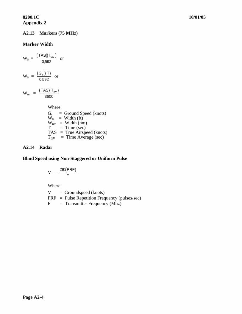
8200.1C 10/01/05 Appendix 2
Page A2-4
A2.13 Markers (75 MHz) Marker Width
Wft = TAS Tav
0 592, or
Wft = G Ts
0 592. or
Wnm = TAS Tav
3600
Where: Gs = Ground Speed (knots) Wft = Width (ft) Wnm = Width (nm) T = Time (sec) TAS = True Airspeed (knots) Tav = Time Average (sec)
A2.14 Radar Blind Speed using Non-Staggered or Uniform Pulse
V = 291PRF
F
Where:
V = Groundspeed (knots) PRF = Pulse Repetition Frequency (pulses/sec) F = Transmitter Frequency (Mhz)
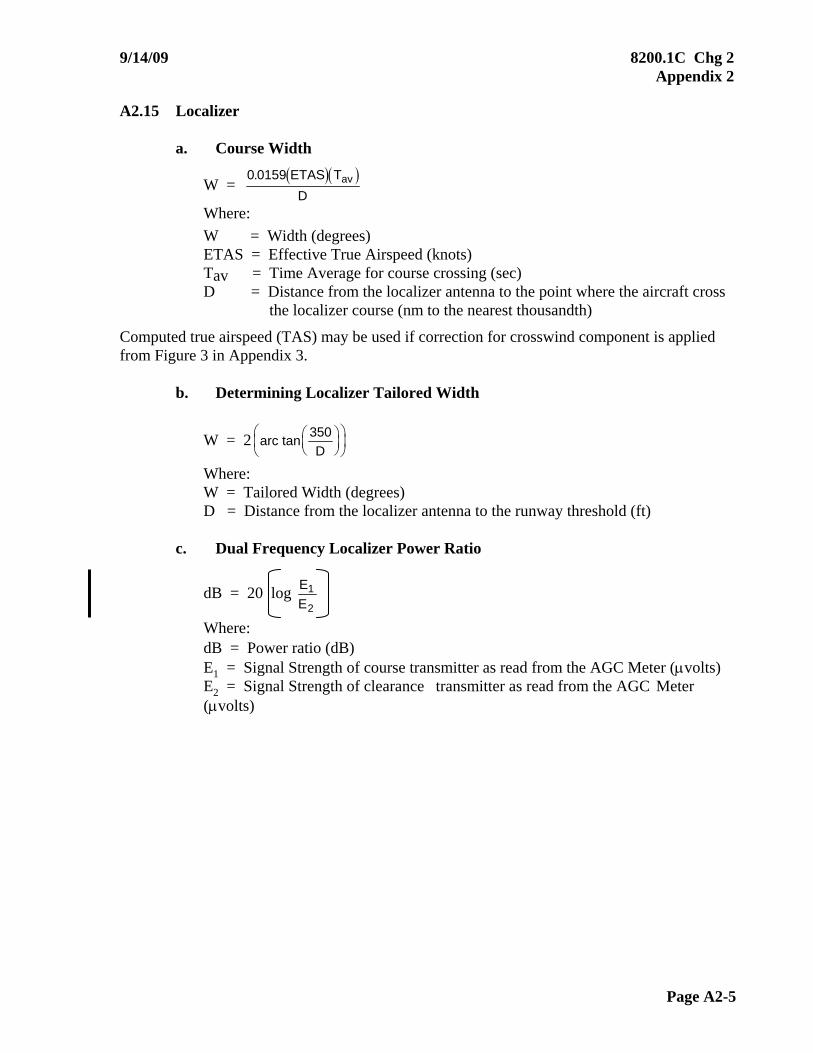
9/14/09 8200.1C Chg 2 Appendix 2
Page A2-5
A2.15 Localizer
a. Course Width
W = 0 0159. ETAS T
Dav
Where:
W = Width (degrees) ETAS = Effective True Airspeed (knots) Tav = Time Average for course crossing (sec) D = Distance from the localizer antenna to the point where the aircraft cross
the localizer course (nm to the nearest thousandth)
Computed true airspeed (TAS) may be used if correction for crosswind component is applied from Figure 3 in Appendix 3.
b. Determining Localizer Tailored Width
W = 2 arc tanD
350
Where: W = Tailored Width (degrees) D = Distance from the localizer antenna to the runway threshold (ft)
c. Dual Frequency Localizer Power Ratio
dB = 20 log E
E1
2
Where: dB = Power ratio (dB) E1 = Signal Strength of course transmitter as read from the AGC Meter (volts) E2 = Signal Strength of clearance transmitter as read from the AGC Meter (volts)

8200.1C 10/01/05 Appendix 2
Page A2-6
A2.16 Glide Slope Glidepath Width or Angles
= arc tan A
D F
Where:
= Angle (degrees) A = Absolute (Tapeline) altitude (ft) above the glide slope antenna D = Geodetic distance (ft) from the glide slope antenna to the outer marker (or checkpoint)
F = 6076.1 VT
3600
NOTE: F is a factor. The value and sign (plus or minus) is determined by the location of the computation point on the recording.
Assign a minus value to F if T occurs between the outer marker (or checkpoint) and the facility
Assign a plus value to F if T occurs prior to the outer marker (or checkpoint)
V = Ground speed (knots) T = Time to computation point (e.g., 75A, 150HZ, 0A, 75A 90Hz for path width, and angle) Glideslope distance – Threshold to Point C calculation: See FAA Order 8240.36, Appendix 22, Paragraphs 59, 60, and 63.
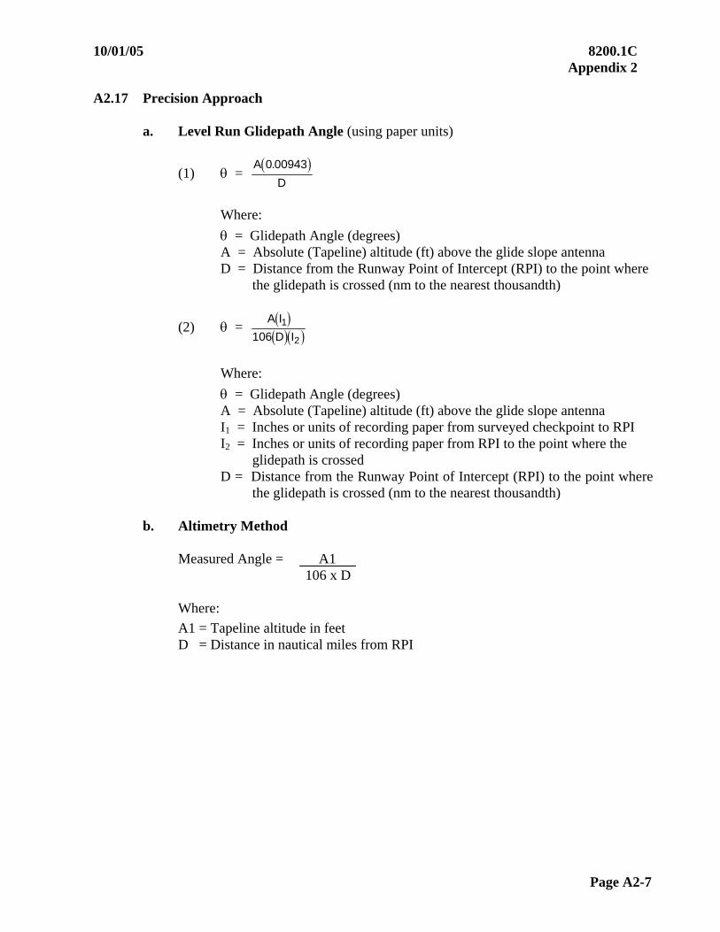
10/01/05 8200.1C Appendix 2
Page A2-7
A2.17 Precision Approach
a. Level Run Glidepath Angle (using paper units)
(1) = A
D
0 00943.
Where:
= Glidepath Angle (degrees) A = Absolute (Tapeline) altitude (ft) above the glide slope antenna D = Distance from the Runway Point of Intercept (RPI) to the point where
the glidepath is crossed (nm to the nearest thousandth)
(2) =
A I
D I1
2106
Where:
= Glidepath Angle (degrees) A = Absolute (Tapeline) altitude (ft) above the glide slope antenna I1 = Inches or units of recording paper from surveyed checkpoint to RPI I2 = Inches or units of recording paper from RPI to the point where the
glidepath is crossed D = Distance from the Runway Point of Intercept (RPI) to the point where
the glidepath is crossed (nm to the nearest thousandth)
b. Altimetry Method
Measured Angle = A1 106 x D
Where:
A1 = Tapeline altitude in feet D = Distance in nautical miles from RPI
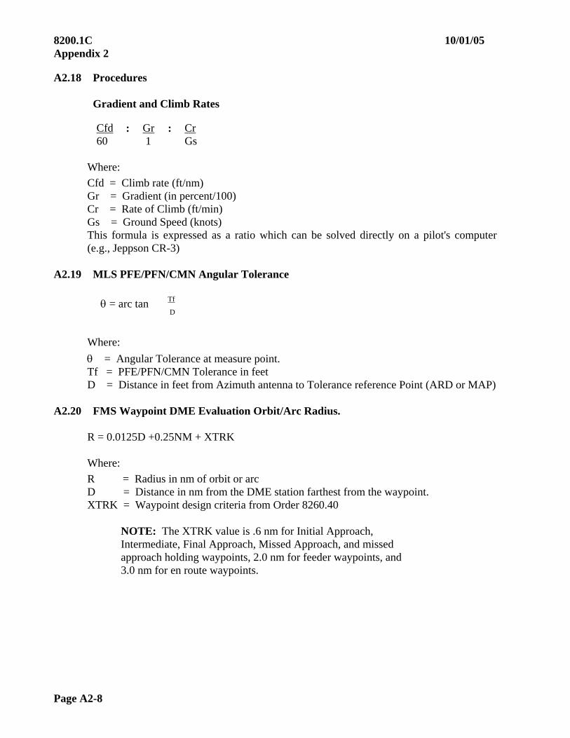
8200.1C 10/01/05 Appendix 2
Page A2-8
A2.18 Procedures
Gradient and Climb Rates
Cfd 60
: Gr 1
: Cr Gs
Where:
Cfd = Climb rate (ft/nm) Gr = Gradient (in percent/100) Cr = Rate of Climb (ft/min) Gs = Ground Speed (knots) This formula is expressed as a ratio which can be solved directly on a pilot's computer (e.g., Jeppson CR-3)
A2.19 MLS PFE/PFN/CMN Angular Tolerance
= arc tan Tf
D
Where:
= Angular Tolerance at measure point. Tf = PFE/PFN/CMN Tolerance in feet D = Distance in feet from Azimuth antenna to Tolerance reference Point (ARD or MAP)
A2.20 FMS Waypoint DME Evaluation Orbit/Arc Radius.
R = 0.0125D +0.25NM + XTRK Where:
R = Radius in nm of orbit or arc D = Distance in nm from the DME station farthest from the waypoint. XTRK = Waypoint design criteria from Order 8260.40
NOTE: The XTRK value is .6 nm for Initial Approach, Intermediate, Final Approach, Missed Approach, and missed approach holding waypoints, 2.0 nm for feeder waypoints, and 3.0 nm for en route waypoints.
10/01/05 8200.1C Appendix 3
Page A3-i (and ii)
APPENDIX 3. WORKING GRAPHS AND CHARTS
Figure Title Page Figure A3-1 Radio Line of Sight Chart ....................................................................... A3-1 Figure A3-2 Correction for Earth Curvature ............................................................... A3-2 Figure A3-3 Tailored Localizer Course Width............................................................ A3-3 Figure A3-4A ILS Structure Tolerances......................................................................... A3-4 Figure A3-4B Back Course and Localizer Only Structure Tolerances .......................... A3-5 Figure A3-5A Standard High Altitude Service Volume................................................. A3-6 Figure A3-5B Standard Low Altitude Service Volume ................................................. A3-7 Figure A3-5C Standard Terminal Service Volume ........................................................ A3-7 Figure A3-5D VOR/DME/TACAN Standard Service Volume...................................... A3-8 Figure A3-5E Service Volume Lower Edge Terminal................................................... A3-8 Figure A3-5F Service Volume Lower Edge Standard High and Low ........................... A3-8 Figure A3-6A VOR Sensing and Rotation ..................................................................... A3-9 Figure A3-6B TACAN Sensing and Rotation ............................................................... A3-9 Figure A3-7 Intersections (Coverage) ......................................................................... A3-10


10/01/05 8200.1C Appendix 3
Fig A3-1 Page A3-1
RADIO LINE OF SIGHT CHART Figure A3-1

8200.1C 10/01/05 Appendix 3
Page A3-2 Fig A3-2
CORRECTION FOR EARTH CURVATURE Figure A3-2

10/01/05 8200.1C Appendix 3
Fig A3-3 Page A3-3
TAILORED LOCALIZER COURSE WIDTH Figure A3-3
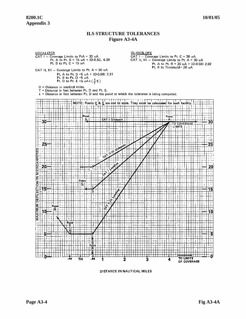
8200.1C 10/01/05 Appendix 3
Page A3-4 Fig A3-4A
ILS STRUCTURE TOLERANCES Figure A3-4A
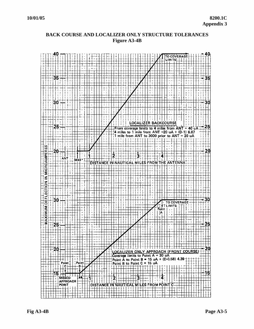
10/01/05 8200.1C Appendix 3
Fig A3-4B Page A3-5
BACK COURSE AND LOCALIZER ONLY STRUCTURE TOLERANCES Figure A3-4B

8200.1C 10/01/05 Appendix 3
Page A3-6 Fig A3-5A
NAVAID Service Volumes. Most air navigation radio aids, which provide positive course guidance, have a designated standard service volume (SSV).
a. VOR/ DME/ TACAN Standard Service Volumes are illustrated in Figures 303-5A-F.
b. All elevations shown are with respect to the station’s site elevation (AGL).
Coverage is not available in a cone of airspace directly above the facility.
Figure A3-5A Standard High Altitude Service Volume
(See Figure A3-5F for altitudes below 1,000 ft.)
60,000 ft.
45,000 ft.
18,000 ft.14,500 ft.
1,000 ft.
100 nm
130 nm
40 nm

10/01/05 8200.1C Appendix 3
Fig A3-5B Page A3-7
Figure A3-5B Standard Low Altitude Service Volume
(See Figure A3-5F for altitudes below 1,000 ft.)
Figure A3-5C Standard Terminal Service Volume
(See Figure A3-5E for altitudes below 1,000 ft.)
40 nm 18,000 ft.
1,000 ft.
12,000 ft. 25 nm
1,000 ft.
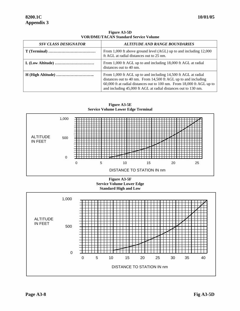
8200.1C 10/01/05 Appendix 3
Page A3-8 Fig A3-5D
Figure A3-5D VOR/DME/TACAN Standard Service Volume
SSV CLASS DESIGNATOR ALTITUDE AND RANGE BOUNDARIES
T (Terminal) ……………………………… From 1,000 ft above ground level (AGL) up to and including 12,000 ft AGL at radial distances out to 25 nm.
L (Low Altitude) ………………………… From 1,000 ft AGL up to and including 18,000 ft AGL at radial distances out to 40 nm.
H (High Altitude) ……………………….. From 1,000 ft AGL up to and including 14,500 ft AGL at radial distances out to 40 nm. From 14,500 ft AGL up to and including 60,000 ft at radial distances out to 100 nm. From 18,000 ft AGL up to and including 45,000 ft AGL at radial distances out to 130 nm.
Figure A3-5E
Service Volume Lower Edge Terminal
Figure A3-5F Service Volume Lower Edge
Standard High and Low
1,000
500
0
ALTITUDE IN FEET
0 5 10 15 20 25
DISTANCE TO STATION IN nm
1,000
500
0
ALTITUDE IN FEET
0 5 10 15 20 25 30 35 40
DISTANCE TO STATION IN nm

10/01/05 8200.1C Appendix 3
Fig A3-6A Page A3-9
Figure A3-6A. VOR Sensing and Rotation
Figure 303-6B
TACAN Sensing and Rotation
Figure A3-6B. TACAN Sensing and Rotation
270 270 090090
0 180
270
0
090 090 270
180
180
180 0
0
Normal Reverse Sensing
Reverse Rotation
Reverse Sensing/ Reverse Rotation
090 090 270o 270
180
0o
270
0
090 090 270
180
180
0
0
Normal Reverse Sensing
Reverse Rotation Reverse Sensing/ Reverse Rotation
180
090 090
180
270

8200.1C 10/01/05 Appendix 3
Page A3-10 Fig A3-7
Figure A3-7 INTERSECTIONS (Coverage)
Primary radials = 4 nm or 4.5, whichever is greater NDB’s Crossing Radial (not primary)
Dis. From fac in nm Deg. Off course = to 4 nm 5 38.7 5 3.6 6 33.7 5 3.6 7 29.7 5 3.6 8 26.6 5 3.6 9 24.0 5 3.6
10 21.8 5 3.6 11 20.0 5 3.6 12 18.4 5 3.6 13 17.1 5 3.6 14 15.9 5 3.6 15 14.9 5 3.6 16 14.0 5 3.6 17 13.2 5 3.6 18 12.5 5 3.6 19 11.9 5 3.6 20 11.3 5 3.6 21 10.8 5 3.6 22 10.3 5 3.6 23 9.9 5 3.6 24 9.5 5 3.6 25 9.1 5 3.6 26 8.7 5 3.6 27 8.4 5 3.6 28 8.1 5 3.6 29 7.9 5 3.6 30 7.6 5 3.6 31 7.4 5 3.6 32 7.1 5 3.6 33 6.9 5 3.6 34 6.7 5 3.6 35 6.5 5 3.6 36 6.3 5 3.6 37 6.2 5 3.6 38 6.0 5 3.6 39 5.9 5 3.6 40 5.7 5 3.6 41 5.6 5 3.6 42 5.4 5 3.6 43 5.3 5 3.6 44 5.2 5 3.6 45 5.1 5 3.6 46 5.0 5 3.6 47 4.9 5 3.6 48 4.8 5 3.6 49 4.7 5 3.6
50.8 4.5 5 3.6
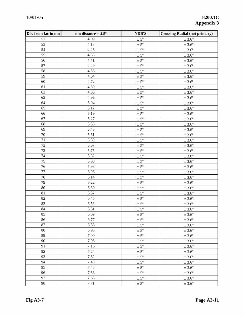
10/01/05 8200.1C Appendix 3
Fig A3-7 Page A3-11
Dis. from fac in nm nm distance = 4.5 NDB'S Crossing Radial (not primary) 52 4.09 5 3.6 53 4.17 5 3.6 54 4.25 5 3.6 55 4.33 5 3.6 56 4.41 5 3.6 57 4.49 5 3.6 58 4.56 5 3.6 59 4.64 5 3.6 60 4.72 5 3.6 61 4.80 5 3.6 62 4.88 5 3.6 63 4.96 5 3.6 64 5.04 5 3.6 65 5.12 5 3.6 66 5.19 5 3.6 67 5.27 5 3.6 68 5.35 5 3.6 69 5.43 5 3.6 70 5.51 5 3.6 71 5.59 5 3.6 72 5.67 5 3.6 73 5.75 5 3.6 74 5.82 5 3.6 75 5.90 5 3.6 76 5.98 5 3.6 77 6.06 5 3.6 78 6.14 5 3.6 79 6.22 5 3.6 80 6.30 5 3.6 81 6.37 5 3.6 82 6.45 5 3.6 83 6.53 5 3.6 84 6.61 5 3.6 85 6.69 5 3.6 86 6.77 5 3.6 87 6.85 5 3.6 88 6.93 5 3.6 89 7.00 5 3.6 90 7.08 5 3.6 91 7.16 5 3.6 92 7.24 5 3.6 93 7.32 5 3.6 94 7.40 5 3.6 95 7.48 5 3.6 96 7.56 5 3.6 97 7.63 5 3.6 98 7.71 5 3.6
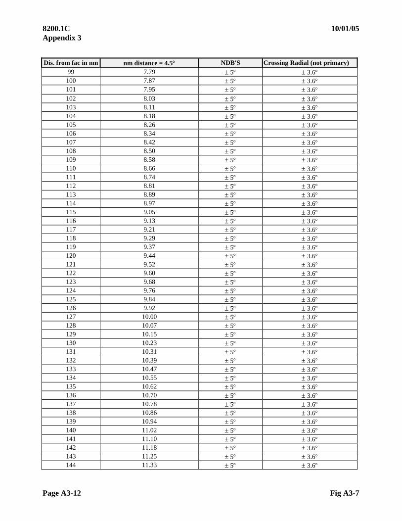
8200.1C 10/01/05 Appendix 3
Page A3-12 Fig A3-7
Dis. from fac in nm nm distance = 4.5 NDB'S Crossing Radial (not primary)
99 7.79 5 3.6 100 7.87 5 3.6 101 7.95 5 3.6 102 8.03 5 3.6 103 8.11 5 3.6 104 8.18 5 3.6 105 8.26 5 3.6 106 8.34 5 3.6 107 8.42 5 3.6 108 8.50 5 3.6 109 8.58 5 3.6 110 8.66 5 3.6 111 8.74 5 3.6 112 8.81 5 3.6 113 8.89 5 3.6 114 8.97 5 3.6 115 9.05 5 3.6 116 9.13 5 3.6 117 9.21 5 3.6 118 9.29 5 3.6 119 9.37 5 3.6 120 9.44 5 3.6 121 9.52 5 3.6 122 9.60 5 3.6 123 9.68 5 3.6 124 9.76 5 3.6 125 9.84 5 3.6 126 9.92 5 3.6 127 10.00 5 3.6 128 10.07 5 3.6 129 10.15 5 3.6 130 10.23 5 3.6 131 10.31 5 3.6 132 10.39 5 3.6 133 10.47 5 3.6 134 10.55 5 3.6 135 10.62 5 3.6 136 10.70 5 3.6 137 10.78 5 3.6 138 10.86 5 3.6 139 10.94 5 3.6 140 11.02 5 3.6 141 11.10 5 3.6 142 11.18 5 3.6 143 11.25 5 3.6 144 11.33 5 3.6

10/01/05 8200.1C Appendix 3
Fig A3-7 Page A3-13
Dis. from fac in nm nm distance = 4.5 NDB'S Crossing Radial (not primary)
145 11.41 5 3.6 146 11.49 5 3.6 147 11.57 5 3.6 148 11.65 5 3.6 149 11.73 5 3.6 150 11.81 5 3.6 151 11.88 5 3.6 152 11.96 5 3.6 153 12.04 5 3.6 154 12.12 5 3.6 155 12.20 5 3.6 156 12.28 5 3.6 157 12.36 5 3.6 158 12.43 5 3.6 159 12.51 5 3.6 160 12.59 5 3.6 161 12.67 5 3.6 162 12.75 5 3.6 163 12.83 5 3.6 164 12.91 5 3.6 165 12.99 5 3.6 166 13.06 5 3.6 167 13.14 5 3.6 168 13.22 5 3.6 169 13.30 5 3.6 170 13.38 5 3.6 171 13.46 5 3.6 172 13.54 5 3.6 173 13.62 5 3.6 174 13.69 5 3.6 175 13.77 5 3.6 176 13.85 5 3.6 177 13.93 5 3.6 178 14.01 5 3.6 179 14.09 5 3.6 180 14.17 5 3.6 181 14.25 5 3.6 182 14.32 5 3.6 183 14.40 5 3.6 184 14.48 5 3.6 185 14.56 5 3.6 186 14.64 5 3.6 187 14.72 5 3.6 188 14.80 5 3.6 189 14.87 5 3.6

8200.1C 10/01/05 Appendix 3
Page A3-14 Fig A3-7
Dis. from fac in nm nm distance = 4.5 NDB'S Crossing Radial (not primary)
190 14.95 5 3.6 191 15.03 5 3.6 192 15.11 5 3.6 193 15.19 5 3.6 194 15.27 5 3.6 195 15.35 5 3.6 196 15.43 5 3.6 197 15.50 5 3.6 198 15.58 5 3.6 199 15.66 5 3.6 200 15.74 5 3.6
10/01/05 8200.1C Appendix 4
Page A4-i (and ii)
APPENDIX 4. FREQUENCY SPECTRUM
TABLE OF CONTENTS
Paragraphs Title Pages
A4.10 FREQUENCY ALLOCATION ....................................................................A4-1
A4.11 NOMENCLATURE OF FREQUENCY BANDS.........................................A4-3
a. International.......................................................................................A4-3 b. VHF/ UHF NAVAID Frequency Channeling and Pairing................A4-3

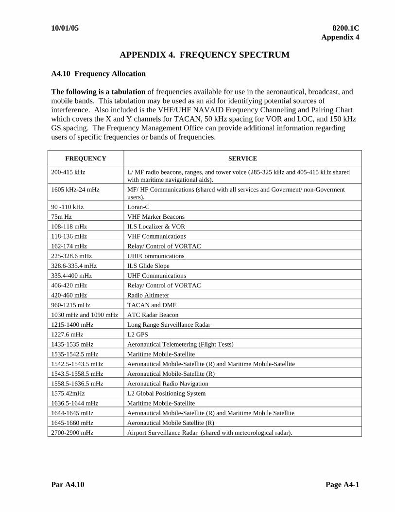
10/01/05 8200.1C Appendix 4
Par A4.10 Page A4-1
APPENDIX 4. FREQUENCY SPECTRUM A4.10 Frequency Allocation The following is a tabulation of frequencies available for use in the aeronautical, broadcast, and mobile bands. This tabulation may be used as an aid for identifying potential sources of interference. Also included is the VHF/UHF NAVAID Frequency Channeling and Pairing Chart which covers the X and Y channels for TACAN, 50 kHz spacing for VOR and LOC, and 150 kHz GS spacing. The Frequency Management Office can provide additional information regarding users of specific frequencies or bands of frequencies.
FREQUENCY SERVICE
200-415 kHz L/ MF radio beacons, ranges, and tower voice (285-325 kHz and 405-415 kHz shared with maritime navigational aids).
1605 kHz-24 mHz MF/ HF Communications (shared with all services and Goverment/ non-Goverment users).
90 -110 kHz Loran-C
75m Hz VHF Marker Beacons
108-118 mHz ILS Localizer & VOR
118-136 mHz VHF Communications
162-174 mHz Relay/ Control of VORTAC
225-328.6 mHz UHFCommunications
328.6-335.4 mHz ILS Glide Slope
335.4-400 mHz UHF Communications
406-420 mHz Relay/ Control of VORTAC
420-460 mHz Radio Altimeter
960-1215 mHz TACAN and DME
1030 mHz and 1090 mHz ATC Radar Beacon
1215-1400 mHz Long Range Surveillance Radar
1227.6 mHz L2 GPS
1435-1535 mHz Aeronautical Telemetering (Flight Tests)
1535-1542.5 mHz Maritime Mobile-Satellite
1542.5-1543.5 mHz Aeronautical Mobile-Satellite (R) and Maritime Mobile-Satellite
1543.5-1558.5 mHz Aeronautical Mobile-Satellite (R)
1558.5-1636.5 mHz Aeronautical Radio Navigation
1575.42mHz L2 Global Positioning System
1636.5-1644 mHz Maritime Mobile-Satellite
1644-1645 mHz Aeronautical Mobile-Satellite (R) and Maritime Mobile Satellite
1645-1660 mHz Aeronautical Mobile Satellite (R)
2700-2900 mHz Airport Surveillance Radar (shared with meteorological radar).
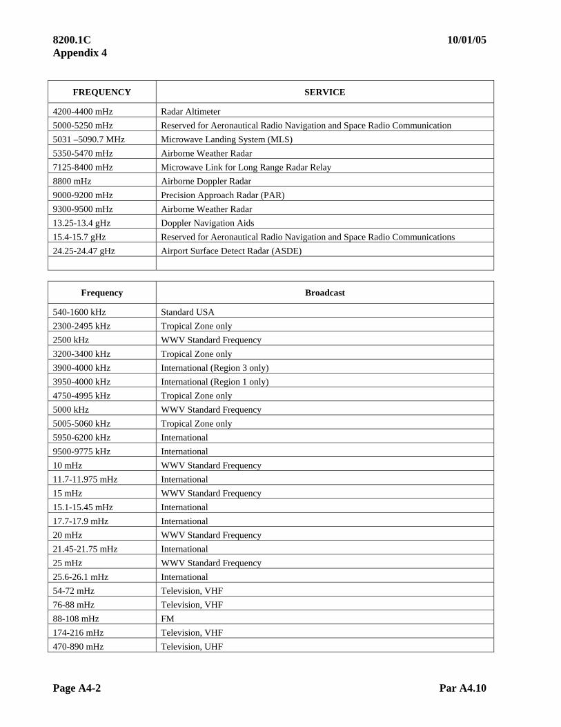
8200.1C 10/01/05 Appendix 4
Page A4-2 Par A4.10
FREQUENCY SERVICE
4200-4400 mHz Radar Altimeter
5000-5250 mHz Reserved for Aeronautical Radio Navigation and Space Radio Communication
5031 –5090.7 MHz Microwave Landing System (MLS)
5350-5470 mHz Airborne Weather Radar
7125-8400 mHz Microwave Link for Long Range Radar Relay
8800 mHz Airborne Doppler Radar
9000-9200 mHz Precision Approach Radar (PAR)
9300-9500 mHz Airborne Weather Radar
13.25-13.4 gHz Doppler Navigation Aids
15.4-15.7 gHz Reserved for Aeronautical Radio Navigation and Space Radio Communications
24.25-24.47 gHz Airport Surface Detect Radar (ASDE)
Frequency Broadcast
540-1600 kHz Standard USA
2300-2495 kHz Tropical Zone only
2500 kHz WWV Standard Frequency
3200-3400 kHz Tropical Zone only
3900-4000 kHz International (Region 3 only)
3950-4000 kHz International (Region 1 only)
4750-4995 kHz Tropical Zone only
5000 kHz WWV Standard Frequency
5005-5060 kHz Tropical Zone only
5950-6200 kHz International
9500-9775 kHz International
10 mHz WWV Standard Frequency
11.7-11.975 mHz International
15 mHz WWV Standard Frequency
15.1-15.45 mHz International
17.7-17.9 mHz International
20 mHz WWV Standard Frequency
21.45-21.75 mHz International
25 mHz WWV Standard Frequency
25.6-26.1 mHz International
54-72 mHz Television, VHF
76-88 mHz Television, VHF
88-108 mHz FM
174-216 mHz Television, VHF
470-890 mHz Television, UHF

10/01/05 8200.1C Appendix 4
Par A4.11 Page A4-3
A4.11 NOMENCLATURE OF FREQUENCY BANDS
a. International
VLF Very Low Frequency 0 - 30 kHz LF Low Frequency 30 - 300 kHz MF Medium Frequency 300 - 3,000 kHz HF High Frequency 3,000 - 30,000 kHz VHF Very High Frequency 30,000 kHz - 300 mHz UHF Ultra High Frequency 300 - 3,000 mHz SHF Super High Frequency 3,000 - 30,000 mHz EHF Extremely High Frequency 30,000 - 300,000 mHz
The shaded frequencies are, for AFIS use, paired communications frequencies that correspond to the indicated TACAN channel.
b. VHF/ UHF NAVAID FREQUENCY CHANNELING AND PAIRING
DME AIRBORNE DME GND INTERROGATE REPLY
PULSE CODE NORMAL P/ DME -------------FREQUENCY-------- DME IA FA DME PC
LOC GS VHF/ MLS FREQ us us us FREQ us DM
E
CH
AN
NE
L
NU
MB
ER
VOR
ML
S
CH
AN
NE
L
NU
MB
ER
1X - - 134.40 - - 1025 12 -- -- 962 12 1Y - - 134.45 - - 1025 36 -- -- 1088 30 2X - - 134.50 - - 1026 12 -- -- 963 12 2Y - - 134.55 - - 1026 36 -- -- 1089 30 3X - - 134.60 - - 1027 12 -- -- 964 12 3Y - - 134.65 - - 1027 36 -- -- 1090 30 4X - - 134.70 - - 1028 12 -- -- 965 12 4Y - - 134.75 - - 1028 36 -- -- 1091 30 5X - - 134.80 - - 1029 12 -- -- 966 12 5Y - - 134.85 - - 1029 36 - - 1092 30 6X - - 134.90 - - 1030 12 - - 967 12 6Y - - 134.95 - - 1030 36 - - 1093 30 7X - - 135.00 - - 1031 12 - - 968 12 7Y - - 135.05 - - 1031 36 - - 1094 30 8X - - 135.10 - - 1032 12 - - 969 12 8Y - - 135.15 - - 1032 36 - - 1095 30 9X - - 135.20 - - 1033 12 - - 970 12 9Y - - 135.25 - - 1033 36 - - 1096 30 10X - - 135.30 - - 1034 12 - - 971 12 10Y - - 135.35 - - 1034 36 - - 1097 30 11X - - 135.40 - - 1035 12 - - 972 12 11Y - - 135.45 - - 1035 36 - - 1098 30 12X - - 135.50 - - 1036 12 - - 973 12 12Y - - 135.55 - - 1036 36 - - 1099 30
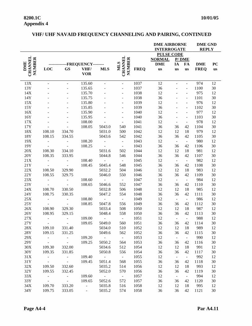
8200.1C 10/01/05 Appendix 4
Page A4-4 Par A4.11
VHF/ UHF NAVAID FREQUENCY CHANNELING AND PAIRING, CONTINUED
DME AIRBORNE DME GND INTERROGATE REPLY
PULSE CODE NORMAL P/ DME -------------FREQUENCY-------- DME IA FA DME PC
LOC GS VHF/ MLS FREQ us us us FREQ us DM
E
CH
AN
NE
L
NU
MB
ER
VOR
ML
S
CH
AN
NE
L
NU
MB
ER
13X - - 135.60 - - 1037 12 - - 974 12 13Y - - 135.65 - - 1037 36 - - 1100 30 14X - - 135.70 - - 1038 12 - - 975 12 14Y - - 135.75 - - 1038 36 - - 1101 30 15X - - 135.80 - - 1039 12 - - 976 12 15Y - - 135.85 - - 1039 36 - - 1102 30 16X - - 135.90 - - 1040 12 - - 977 12 16Y - - 135.95 - - 1040 36 - - 1103 30 17X - - 108.00 - - 1041 12 - - 978 12 17Y - - 108.05 5043.0 540 1041 36 36 42 1104 30 18X 108.10 334.70 5031.0 500 1042 12 12 18 979 12 18Y 108.15 334.55 5043.6 542 1042 36 36 42 1105 30 19X - - 108.20 - - 1043 12 - - 980 12 19Y - - 108.25 - - 1043 36 36 42 1106 30 20X 108.30 334.10 5031.6 502 1044 12 12 18 981 12 20Y 108.35 333.95 5044.8 546 1044 36 36 42 1107 30 21X - - 108.40 - - 1045 12 - - 982 12 21Y - - 108.45 5045.4 548 1045 36 36 42 1108 30 22X 108.50 329.90 5032.2 504 1046 12 12 18 983 12 22Y 108.55 329.75 5046.0 550 1046 36 36 42 1109 30 23X - - 108.60 - - 1047 12 - - 984 12 23Y - - 108.65 5046.6 552 1047 36 36 42 1110 30 24X 108.70 330.50 5032.8 506 1048 12 12 18 985 12 24Y 108.75 330.35 5047.2 554 1048 36 36 42 1111 30 25X - - 108.80 - - 1049 12 - - 986 12 25Y - - 108.85 5047.8 556 1049 36 36 42 1112 30 26X 108.90 329.30 5033.4 508 1050 12 12 18 987 12 26Y 108.95 329.15 5048.4 558 1050 36 36 42 1113 30 27X - - 109.00 - - 1051 12 - - 988 12 27Y - - 109.05 5049.0 560 1051 36 36 42 1114 30 28X 109.10 331.40 5034.0 510 1052 12 12 18 989 12 28Y 109.15 331.25 5049.6 562 1052 36 36 42 1115 30 29X - - 109.20 - - 1053 12 - - 990 12 29Y - - 109.25 5050.2 564 1053 36 36 42 1116 30 30X 109.30 332.00 5034.6 512 1054 12 12 18 991 12 30Y 109.35 331.85 5050.8 556 1054 36 36 42 1117 30 31X - - 109.40 - - 1055 12 - - 992 12 31Y - - 109.45 5051.4 568 1055 36 36 42 1118 30 32X 109.50 332.60 5035.2 514 1056 12 12 18 993 12 32Y 109.55 332.45 5052.0 570 1056 36 36 42 1119 30 33X - - 109.60 - - 1057 12 - - 994 12 33Y - - 109.65 5052.6 572 1057 36 36 42 1120 30 34X 109.70 333.20 - 5035.8 516 1058 12 12 18 995 12 34Y 109.75 333.05 - 5035.2 574 1058 36 36 42 1121 30

10/01/05 8200.1C Appendix 4
Par A4.11 Page A4-5
VHF/ UHF NAVAID FREQUENCY CHANNELING AND PAIRING, CONTINUED
DME AIRBORNE DME GND INTERROGATE REPLY
PULSE CODE NORMAL P/ DME -------------FREQUENCY-------- DME IA FA DME PC
LOC GS VHF/ MLS FREQ us us us FREQ us DM
E
CH
AN
NE
L
NU
MB
ER
VOR
ML
S
CH
AN
NE
L
NU
MB
ER
35X - - 109.80 - - 1059 12 - - 996 12 35Y - - 109.85 5053.8 576 1059 36 36 42 1122 30 36X 109.90 333.80 5036.4 518 1060 12 12 18 997 12 36Y 109.95 333.65 5054.4 578 1060 36 36 42 1123 30 37X - - 110.00 - - 1061 12 - - 998 12 37Y - - 110.05 5055.0 580 1061 36 36 42 1124 30 38X 110.10 334.40 5037.0 520 1062 12 12 18 999 12 38Y 110.15 334.25 39X - - 110.20 - - 1063 12 - - 1000 12 39Y - - 110.25 5056.2 584 1063 36 36 42 1126 30 40X 110.30 335.00 5037.6 522 1064 12 12 18 1001 12 40Y 110.35 334.85 5056.8 586 1064 36 36 42 1127 30 41X - - 110.40 - - 1065 12 - - 1002 12 41Y - - 110.45 5057.4 588 1065 36 36 42 1128 30 42X 110.50 329.60 5038.2 524 1066 12 12 18 1003 12 42Y 110.55 329.45 5058.0 590 1066 36 36 42 1129 30 43X - - 110.60 - - 1067 12 - - 1004 12 43Y - - 110.65 5058.6 592 1067 36 36 42 1130 30 44X 110.70 330.20 5038.8 526 1068 12 12 18 1005 12 44Y 110.75 330.05 5059.2 594 1068 36 36 42 1131 30 45X - - 110.80 - - 1069 12 - - 1006 12 45Y - - 110.85 5059.8 596 1069 36 36 42 1132 30 46X 110.90 330.80 5039.4 528 1070 12 12 18 1007 12 46Y 110.95 330.65 5060.4 598 1070 36 36 42 1133 30 47X - - 111.00 - - 1071 12 - - 1008 12 47Y - - 111.05 5061.0 600 1071 36 36 42 1134 30 48X 111.10 331.70 5040.0 530 1072 12 12 18 1009 12 48Y 111.15 331.55 5061.6 602 1072 36 36 42 1135 30 49X - - 111.20 - - 1073 12 - - 1010 12 49Y - - 111.25 6062.2 604 1073 36 36 42 1136 30 50X 111.30 332.30 5040.6 532 1074 12 12 18 1011 12 50Y 111.35 332.15 5062.8 606 1074 36 36 42 1137 30 51X - - 111.40 - - 1075 12 - - 1012 12 51Y - - 111.45 5063.4 608 1075 36 36 42 1136 30 52X 111.50 332.90 5041.2 534 1076 12 12 18 1013 12 52Y 111.55 332.75 5064.0 610 1076 36 36 42 1139 30 53X - - 111.60 - - 1077 12 - - 1014 12 53Y - - 111.65 5064.4 612 1077 36 36 42 1140 30 54X 111.70 333.50 5041.8 536 1078 12 12 18 1015 12 54Y 111.75 333.35 5065.2 614 1078 36 36 42 1141 30 55X - - 111.80 - - 1079 12 - - 1016 12 55Y - - 111.85 5065.8 616 1079 36 36 42 1142 30
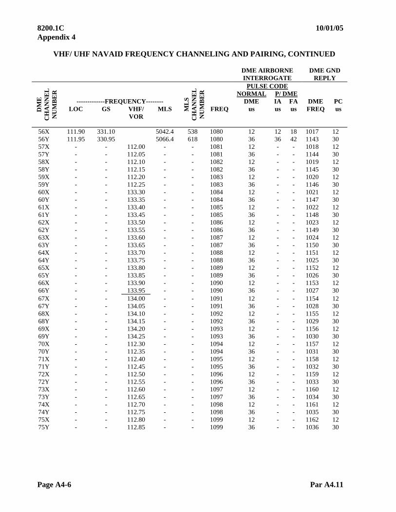
8200.1C 10/01/05 Appendix 4
Page A4-6 Par A4.11
VHF/ UHF NAVAID FREQUENCY CHANNELING AND PAIRING, CONTINUED
DME AIRBORNE DME GND INTERROGATE REPLY
PULSE CODE NORMAL P/ DME -------------FREQUENCY-------- DME IA FA DME PC
LOC GS VHF/ MLS FREQ us us us FREQ us DM
E
CH
AN
NE
L
NU
MB
ER
VOR
ML
S
CH
AN
NE
L
NU
MB
ER
56X 111.90 331.10 5042.4 538 1080 12 12 18 1017 12 56Y 111.95 330.95 5066.4 618 1080 36 36 42 1143 30 57X - - 112.00 - - 1081 12 - - 1018 12 57Y - - 112.05 - - 1081 36 - - 1144 30 58X - - 112.10 - - 1082 12 - - 1019 12 58Y - - 112.15 - - 1082 36 - - 1145 30 59X - - 112.20 - - 1083 12 - - 1020 12 59Y - - 112.25 - - 1083 36 - - 1146 30 60X - - 133.30 - - 1084 12 - - 1021 12 60Y - - 133.35 - - 1084 36 - - 1147 30 61X - - 133.40 - - 1085 12 - - 1022 12 61Y - - 133.45 - - 1085 36 - - 1148 30 62X - - 133.50 - - 1086 12 - - 1023 12 62Y - - 133.55 - - 1086 36 - - 1149 30 63X - - 133.60 - - 1087 12 - - 1024 12 63Y - - 133.65 - - 1087 36 - - 1150 30 64X - - 133.70 - - 1088 12 - - 1151 12 64Y - - 133.75 - - 1088 36 - - 1025 30 65X - - 133.80 - - 1089 12 - - 1152 12 65Y - - 133.85 - - 1089 36 - - 1026 30 66X - - 133.90 - - 1090 12 - - 1153 12 66Y - - 133.95 - - 1090 36 - - 1027 30 67X - - 134.00 - - 1091 12 - - 1154 12 67Y - - 134.05 - - 1091 36 - - 1028 30 68X - - 134.10 - - 1092 12 - - 1155 12 68Y - - 134.15 - - 1092 36 - - 1029 30 69X - - 134.20 - - 1093 12 - - 1156 12 69Y - - 134.25 - - 1093 36 - - 1030 30 70X - - 112.30 - - 1094 12 - - 1157 12 70Y - - 112.35 - - 1094 36 - - 1031 30 71X - - 112.40 - - 1095 12 - - 1158 12 71Y - - 112.45 - - 1095 36 - - 1032 30 72X - - 112.50 - - 1096 12 - - 1159 12 72Y - - 112.55 - - 1096 36 - - 1033 30 73X - - 112.60 - - 1097 12 - - 1160 12 73Y - - 112.65 - - 1097 36 - - 1034 30 74X - - 112.70 - - 1098 12 - - 1161 12 74Y - - 112.75 - - 1098 36 - - 1035 30 75X - - 112.80 - - 1099 12 - - 1162 12 75Y - - 112.85 - - 1099 36 - - 1036 30
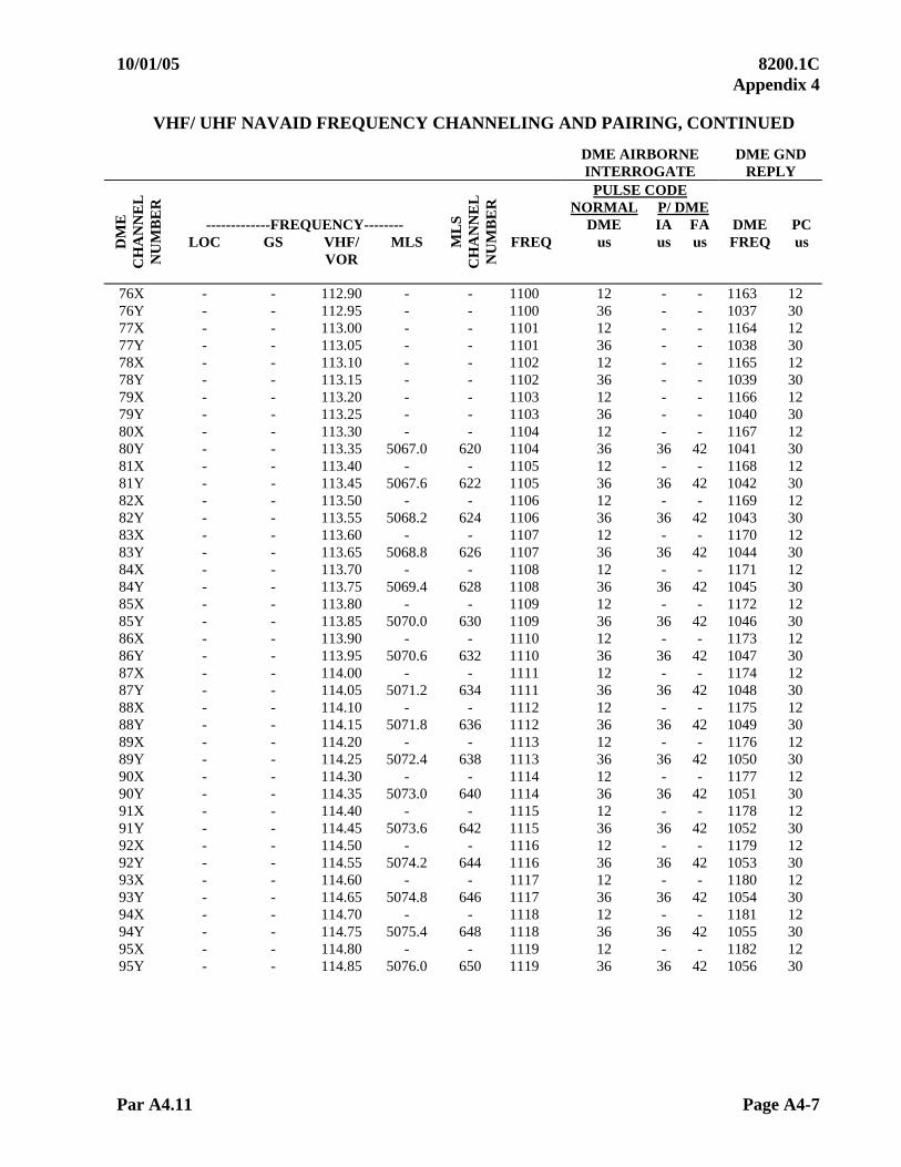
10/01/05 8200.1C Appendix 4
Par A4.11 Page A4-7
VHF/ UHF NAVAID FREQUENCY CHANNELING AND PAIRING, CONTINUED
DME AIRBORNE DME GND INTERROGATE REPLY
PULSE CODE NORMAL P/ DME -------------FREQUENCY-------- DME IA FA DME PC
LOC GS VHF/ MLS FREQ us us us FREQ us DM
E
CH
AN
NE
L
NU
MB
ER
VOR
ML
S
CH
AN
NE
L
NU
MB
ER
76X - - 112.90 - - 1100 12 - - 1163 12 76Y - - 112.95 - - 1100 36 - - 1037 30 77X - - 113.00 - - 1101 12 - - 1164 12 77Y - - 113.05 - - 1101 36 - - 1038 30 78X - - 113.10 - - 1102 12 - - 1165 12 78Y - - 113.15 - - 1102 36 - - 1039 30 79X - - 113.20 - - 1103 12 - - 1166 12 79Y - - 113.25 - - 1103 36 - - 1040 30 80X - - 113.30 - - 1104 12 - - 1167 12 80Y - - 113.35 5067.0 620 1104 36 36 42 1041 30 81X - - 113.40 - - 1105 12 - - 1168 12 81Y - - 113.45 5067.6 622 1105 36 36 42 1042 30 82X - - 113.50 - - 1106 12 - - 1169 12 82Y - - 113.55 5068.2 624 1106 36 36 42 1043 30 83X - - 113.60 - - 1107 12 - - 1170 12 83Y - - 113.65 5068.8 626 1107 36 36 42 1044 30 84X - - 113.70 - - 1108 12 - - 1171 12 84Y - - 113.75 5069.4 628 1108 36 36 42 1045 30 85X - - 113.80 - - 1109 12 - - 1172 12 85Y - - 113.85 5070.0 630 1109 36 36 42 1046 30 86X - - 113.90 - - 1110 12 - - 1173 12 86Y - - 113.95 5070.6 632 1110 36 36 42 1047 30 87X - - 114.00 - - 1111 12 - - 1174 12 87Y - - 114.05 5071.2 634 1111 36 36 42 1048 30 88X - - 114.10 - - 1112 12 - - 1175 12 88Y - - 114.15 5071.8 636 1112 36 36 42 1049 30 89X - - 114.20 - - 1113 12 - - 1176 12 89Y - - 114.25 5072.4 638 1113 36 36 42 1050 30 90X - - 114.30 - - 1114 12 - - 1177 12 90Y - - 114.35 5073.0 640 1114 36 36 42 1051 30 91X - - 114.40 - - 1115 12 - - 1178 12 91Y - - 114.45 5073.6 642 1115 36 36 42 1052 30 92X - - 114.50 - - 1116 12 - - 1179 12 92Y - - 114.55 5074.2 644 1116 36 36 42 1053 30 93X - - 114.60 - - 1117 12 - - 1180 12 93Y - - 114.65 5074.8 646 1117 36 36 42 1054 30 94X - - 114.70 - - 1118 12 - - 1181 12 94Y - - 114.75 5075.4 648 1118 36 36 42 1055 30 95X - - 114.80 - - 1119 12 - - 1182 12 95Y - - 114.85 5076.0 650 1119 36 36 42 1056 30

8200.1C 10/01/05 Appendix 4
Page A4-8 Par A4.11
VHF/ UHF NAVAID FREQUENCY CHANNELING AND PAIRING, CONTINUED
DME AIRBORNE DME GND INTERROGATE REPLY
PULSE CODE NORMAL P/ DME -------------FREQUENCY-------- DME IA FA DME PC
LOC GS VHF/ MLS FREQ us us us FREQ us DM
E
CH
AN
NE
L
NU
MB
ER
VOR
ML
S
CH
AN
NE
L
NU
MB
ER
96X - - 114.90 - - 1120 12 - - 1183 12 96Y - - 114.95 5076.6 652 1120 36 36 42 1057 30 97X - - 115.00 - - 1121 12 - - 1184 12 97Y - - 115.05 5077.2 654 1121 36 36 42 1058 30 98X - - 115.10 - - 1122 12 - - 1185 12 98Y - - 115.15 5077.8 656 1122 36 36 42 1059 30 99X - - 115.20 - - 1123 12 - - 1186 12 99Y - - 115.25 5078.4 658 1123 36 36 42 1060 30 100X - - 115.30 - - 1124 12 - - 1187 12 100Y - - 115.35 5079.0 660 1124 36 36 42 1061 30 101X - - 115.40 - - 1125 12 - - 1188 12 101Y - - 115.45 5079.6 662 1125 36 36 42 1062 30 102X - - 115.50 - - 1126 12 - - 1189 12 102Y - - 115.55 5050.2 664 1126 36 36 42 1063 30 103X - - 115.60 - - 1127 12 - - 1190 12 103Y - - 115.65 5080.8 666 1127 36 36 42 1064 30 104X - - 115.70 - - 1128 12 - - 1191 12 104Y - - 115.75 5081.4 668 1128 36 36 42 1065 30 105X - - 115.80 - - 1129 12 - - 1192 12 105Y - - 115.85 5082.0 670 1129 36 36 42 1066 30 106X - - 115.90 - - 1130 12 - - 1193 12 106Y - - 115.95 5082.6 672 1130 36 36 42 1067 30 107X - - 116.00 - - 1131 12 - - 1194 12 107Y - - 116.05 5083.2 674 1131 36 36 42 1068 30 108X - - 116.10 - - 1132 12 - - 1195 12 108Y - - 116.15 5083.8 676 1132 36 36 42 1069 30 109X - - 116.20 - - 1133 12 - - 1196 12 109Y - - 116.25 5084.4 678 1133 36 36 42 1070 30 110X - - 116.30 - - 1134 12 - - 1197 12 110Y - - 116.35 5085.0 680 1134 36 36 42 1071 30 111X - - 116.40 - - 1135 12 - - 1198 12 111Y - - 116.45 5085.6 682 1135 36 36 42 1072 30 112X - - 116.50 - - 1136 12 - - 1199 12 112Y - - 116.55 5086.2 684 1136 36 36 42 1073 30 113X - - 116.60 - - 1137 12 - - 1200 12 113Y - - 116.65 5086.8 686 1137 36 36 42 1074 30 114X - - 116.70 - - 1138 12 - - 1201 12 114Y - - 116.75 5087.4 688 1138 36 36 42 1075 30 115X - - 116.80 - - 1139 12 - - 1202 12 115Y - - 116.85 5088.0 690 1139 36 36 42 1076 30

10/01/05 8200.1C Appendix 4
Par A4.11 Page A4-9 (and 10)
VHF/ UHF NAVAID FREQUENCY CHANNELING AND PAIRING, CONTINUED
DME AIRBORNE DME GND INTERROGATE REPLY
PULSE CODE NORMAL P/ DME -------------FREQUENCY-------- DME IA FA DME PC
LOC GS VHF/ MLS FREQ us us us FREQ us DM
E
CH
AN
NE
L
NU
MB
ER
VOR
ML
S
CH
AN
NE
L
NU
MB
ER
116X - - 116.90 - - 1140 12 - - 1203 12 116Y - - 116.95 5088.6 692 1140 36 36 42 1077 30 117X - - 117.00 - - 1141 12 - - 1204 12 117Y - - 117.05 5089.2 694 1141 36 36 42 1078 30 118X - - 117.10 - - 1142 12 - - 1205 12 118Y - - 117.15 5089.8 696 1142 36 36 42 1079 30 119X - - 117.20 - - 1143 12 - - 1206 12 119Y - - 117.25 5090.4 698 1143 36 36 42 1080 30 120X - - 117.30 - - 1144 12 - - 1207 12 120Y - - 117.35 - - 1144 36 - - 1081 30 121X - - 117.40 - - 1145 12 - - 1208 12 121Y - - 117.45 - - 1145 36 - - 1082 30 122X - - 117.50 - - 1146 12 - - 1209 12 122Y - - 117.55 - - 1146 36 - - 1083 30 123X - - 117.60 - - 1147 12 - - 1210 12 123Y - - 117.65 - - 1147 36 - - 1084 30 124X - - 117.70 - - 1148 12 - - 1211 12 124Y - - 117.75 - - 1148 36 - - 1085 30 125X - - 117.80 - - 1149 12 - - 1212 12 125Y - - 117.85 - - 1149 36 - - 1086 30 126X - - 117.90 - - 1150 12 - - 1213 12 126Y - - 117.95 - - 1150 36 - - 1087 30

10/01/05 8200.1C Appendix 5
Page A5-i (and ii)
APPENDIX 5. MAP INTERPRETATION
TABLE OF CONTENTS Paragraphs Title Pages A5.10 INTRODUCTION.........................................................................................A5-1 A5.11 AERONAUTICAL CHART PREPARATION.............................................A5-1 A5.12 PREPARATION OF CHARTS FOR FLIGHT INSPECTION USE............A5-3 A5.13 USE OF THE CHART ..................................................................................A5-4

10/01/05 8200.1C Appendix 5
Page A5-1
APPENDIX 5. MAP INTERPRETATION A5.10 Introduction
a. Aeronautical charts normally used for checkpoint orbit checks have substantial effect on the data processing center. Through the cooperation of the United States Coast and Geodetic Survey, certain information concerning aeronautical charts has been collected. Coast and Geodetic Survey personnel have accompanied flight crews on orbit type checks. Outlined here is information considered helpful in improving the accuracy of flight inspection results, with particular reference to chart construction, design, and preparation for flight inspection use, checkpoint selection, etc.
b. The use of state highway maps or county maps is not recommended if
aeronautical charts are available, as there is considerable variation in the accuracy of the maps among various states and counties.
c. It has been determined, however, that the Defense Mapping Agency Series 1501,
Joint Operations Graphics, although not aeronautical charts, are satisfactory for flight inspection use. Due to the scale of these maps (1 to 250,000), greater detail is available than that displayed by the sectional charts; consequently more definable checkpoints can be utilized.
d. The positions of many facility sites have been determined by first-order
triangulation or photogrammetric methods with a high degree of accuracy. Before recommending that coordinates of a facility be changed, the Coast and Geodetic Survey should be contacted for verification of such a change.
A5.11 Aeronautical Chart Preparation
a. In congested areas of the Nation, checkpoints are plentiful, and it is possible to select only the most desirable. In sparsely settled areas, it may be necessary to use every feature appearing on the chart in order to obtain a maximum of 8 or 10 checkpoints. For these reasons, it is helpful to have an understanding of the manner in which final drawings for aeronautical charts are made.
b. The preparation of final drawings for charts using three separate colors is
made as follows:
(1) Black. Includes railroads, roads (these are sketched in black, but photograph gray on final chart), city and town symbols, boundaries, dots showing the location of spot heights, landmark symbols, etc.
(2) Blue. Drainage. (3) Brown. Contours.

8200.1C 10/01/05 Appendix 5
Page A5-2
c. In order to provide satisfactory clearances between various features, it is often necessary to shift some away from their correct geographic positions. This shift does not usually amount to more than 1/32 of an inch on the printed chart, but it is often required for increased clarity and legibility of the chart. In shifting, two general conditions are to be met:
(1) All possible detail in the relative position of the features is retained as closely as possible.
(2) The geographic position of the combination of features is retained as closely as possible.
d. For example, in case of a road paralleling a railroad for a short distance, the
railroad is drawn in its true geographic position, and the road is displaced enough to provide the required clearance. If both were displaced by equal amounts, as first might be suspected, a curve that is nonexistent in fact would have to be introduced into the railroad or the railroad would have to be displaced for some little distance on either side, with consequent displacement of towns and other features along the railroad.
e. Similarly, if a road parallels the railroad for a short distance, then crosses and again parallels the railroad on the other side, the railroad should be shown in its correct position and the road displaced as before.
f. Further, there are conditions where a road may parallel a railroad for a short distance, and both may be displaced by an amount equal to one-half the required clearance.
g. In general, it has been found that a railroad should be held in its correct position first, a road second, and stream last. That is, between a railroad and a highway or stream, the latter are usually shifted; between a road and a stream, the stream is displaced.
h. If a stream flows between a road and a railroad, or between two railroads, the stream retains its true position and other features are displaced. As a rule, all town and city symbols are affixed in their correct positions. Since railroads and towns are usually held in their correct positions, other features are adjusted to them. Landmarks such as oil derricks, race-tracks, etc., should be used only as a last resort.
i. Since each color on a printed chart is a separate sheet, the registration of the colors may be checked at the "neat line" at each corner of the chart. The color which is not correct can be identified by the color tick. If a color is too far from correct registration, several charts should be examined and an effort made to obtain one that is more accurate.

10/01/05 8200.1C Appendix 5
Page A5-3
A5.12 Preparation of Charts for Flight Inspection Use. In preparing a chart for a flight inspection, the following procedure is outlined.
a. The exact latitude and longitude of the facility should be plotted on the chart as follows:
(1) Plot the longitude on parallels, which are subdivided into 1-minute
intervals, north and south of the station, then draw a fine line connecting these two points and extend the line far enough in both directions to fit a large protractor. This will be the true north reference. The latitude should be scaled, using hairspring dividers, from the parallel below the site along the nearest meridian, subdivided into 1-minute -intervals, and then be transferred to the true north reference where it intersects the same parallel. Because of curvature in the parallels, this procedure will be far more accurate than measuring the latitude on each side of the site and then drawing a line between the two points of latitude.
(2) If two or more charts must be joined together, such as Kansas City and Des
Moines for the St. Joseph VOR, it is suggested that the following method be used: Select one of the charts which will be used to plot the correct position of the VOR and use it as the overlay chart. For example, the correct position of the STJ VOR is to be plotted on the Kansas City chart. Place a straight edge on the intersection of north lat. 40 05'00" and 94 00'00" west long. Draw a straight line between these two points. The use of a razor blade for cutting along a straight edge is preferred. This chart will be mounted on the Des Moines chart by correctly aligning the central meridian of 95 00'00" and placing the two points mentioned above in their correct position. The slight difference in the size of the two charts will fall away from the central meridian and allow the minimum error near the station. If it is necessary to join four charts together, it is suggested that the two north charts be mounted on the two south charts to form the east and west half, then the east and west sections may be mounted along a meridian such as 96 00'00", making sure that the 40 parallel is in correct alignment and that the 96th meridian is in a straight line.
(3) The magnetic north reference may not be plotted from the facility
location with magnetic variation interpolated from the lines of magnetic variation shown on the chart. The determination of the correct magnetic variation is extremely important. Whenever possible, the magnetic variation should be obtained from the latest information available through the Coast and Geodetic Survey. If the available information is not up to date, the annual rate of change in variation should be applied. It is conceivable that errors as great as 0.5 may occur if proper determination of magnetic variation is not made through use of the latest and most accurate source of this information.
(4) After the magnitude of magnetic variation has been determined, it is
suggested that this be plotted on the chart using at least a 6-inch circular protractor and marking it from the true north reference, both north and south of the site and connecting the two points with a fine line which passes directly through the site. The 90 to 270 magnetic lines may be marked by resetting the protractor on the magnetic north reference.
8200.1C 10/01/05 Appendix 5
Page A5-4
A5.13 Use of the Chart
a. In the selection of checkpoints, black should be used first, gray second, and blue (drainage) last. Only in rare cases will the facility site be accurately located. Consequently, the facility location should always be plotted as outlined above.
b. One good checkpoint each 30 provides more repeatable results (provided
constant radius is maintained) than large numbers of checkpoints using all types of map information.
c. If the same chart is used over an extended period of time, it may be necessary to
realign the magnetic north reference line due to annual change in the variation. This is particularly true in some areas where the annual rate of change is extraordinary.

10/01/05 8200.1C Appendix 6
Page A6-i (and ii)
APPENDIX 6. UHF HOMING BEACONS
TABLE OF CONTENTS Paragraphs Title Pages A6.10 INTRODUCTION.................................................................................A6-1 A6.11 PREFLIGHT REQUIREMENTS..........................................................A6-1 A6.12 FLIGHT INSPECTION PROCEDURES..............................................A6-2 A6.13 ANALYSIS ...........................................................................................A6-4 A6.14 TOLERANCES .....................................................................................A6-4


10/01/05 8200.1C Appendix 6
Page A6-1
APPENDIX 6. UHF HOMING BEACONS A6.10 Introduction
a. The UHF Homing Beacon (AN/ URN-12) ground station transmits a continuous carrier in the frequency range of 275 to 287 megacycles, modulated with a 1,020-cycle tone for identification purposes. The power output is approximately 15 watts.
b. The pilot of an aircraft equipped with the AN/ ARA-25 or similar equipment
can determine the relative bearing of, and "home" on, the Facilities Maintenance equipment. The airborne equipment extracts the information from signals received by the AN/ ARC-27 or similar UHF communications receiver. The relative bearing of the signal source is indicated on a course indicator. Best results are obtained under straight and level flight conditions. A6.11 Preflight Requirements
a. Facilities Maintenance personnel should prepare for flight inspection in accordance with procedures outlined in Paragraph 4.32a..
b. Air. The flight inspector will prepare for the flight inspection in accordance with procedures outlined in Paragraph 4.32b. In addition to the above preparations, the flight inspector will:
(1) Be sure that an approved type of airborne equipment is installed and has
been calibrated and aligned in accordance with current FAA directives.
(2) For commissioning, use a suitable chart, scale 1:500,000 or greater, to plot the exact location of the facility. Plot a series of checkpoints spaced approximately 45 apart at a radius between 20 and 30 nm from the station. Determine the primary air routes that are served by the facility and plot the routes on the chart. Select two courses for a long-distance check.
NOTE: These two courses may be extensions of the primary air routes previously selected, but should be at least 45 apart.

8200.1C 10/01/05 Appendix 6
Page A6-2
A6.12 Flight Inspection Procedures. The primary object of the flight inspection is to determine the coverage and quality of the transmitted signal; therefore, it is necessary that the aircraft be flown through normal usage patterns and procedures to determine the usability of the facility and to ensure that the homing beacon meets the operational requirements for which it was installed.
a. Checklists
Type Check Reference Paragraph
C P
Station identification A6.12b(1) X X Bearing accuracy A6.12b(2) X X Voice A6.12b(3) X X Coverage A6.12b(4) X X Long distance A6.12b(5) X Low approach A6.12b(6) X X Station passage A6.12b(7) X X Standby equipment A6.12b(8) X X Standby power 4.33c X
b. Detailed Procedures.
(1) Station Identification. Select the proper frequency and check for correct
identification and tone of the signal. Any discrepancies noted should be reported to maintenance personnel for corrective action before continuing the flight inspection. Note any frequency interference from other stations.
(2) Bearing Accuracy. Check bearing accuracy against AFIS, GPS, or map reference at least at one point in the service volume, preferably on a published procedure. Fly at minimum instrument altitudes or at an altitude to ensure adequate signal strength.
(3) Voice. If the facility is equipped with voice feature, this feature should be checked at maximum usable distance. It will be noted that most types of airborne equipment will require the receiver function selector to be placed in the RECEIVE position to receive voice transmissions. Request a long voice transmission and note the voice quality, modulation, and freedom from interference. In the event voice transmissions do not reach the maximum usable range, return inbound until they can be received satisfactorily. Record this distance on the flight inspection report.
(4) Coverage
(a) Proceed outbound along one of the primary air routes at minimum instrument altitude until reaching 45 nm or until any out-of-tolerance condition is observed. This position will be the usable distance. Upon completion of the investigation of the first route, proceed to the remaining routes and repeat the above procedures.
10/01/05 8200.1C Appendix 6
Page A6-3
(b) During the check, observe the surrounding terrain and note the location of terrain, or other obstructions that may prevent line-of-sight transmissions to an area beyond the obstructions. Reflections of radio signals, or shadow effect, caused by the intervening terrain, or other obstacles, may result in bearing errors or loss of usable signal.
(c) If areas of weak signal are encountered or if terrain obstructions exist, investigate the areas in question and record the areas checked, location of apparent obstructions, and the minimum altitude and distance at which a usable signal can be received.
(d) For periodic inspections, check coverage from 45 nm at minimum en route altitude until intercepting the approach procedure.
(5) Long-Distance Check. Proceed outbound along one of the air routes or courses selected to a distance of 100 nm at an altitude of 10,000 ft. Observe and record the extent of the pilot's direction indicator needle oscillation, AGC, and the station identification. Then proceed to the other air route or selected course at the 100-mile range and fly inbound along this route to the facility site, again noting the identification, AGC, and needle oscillation.
(6) Standard Instrument Approach Procedure (SIAP). If this facility is to be used as a low approach aid, a low approach will be made for each of the proposed or approved procedures. Check each approach procedure for flyability. Unusual conditions noted will be further investigated. The flight inspector must follow the procedures for inspection of SIAP(s) contained in Chapter 6. Altitudes flown shall be the minimum proposed or published for the segment evaluated, except that the final segment must be flown to 100 ft below the lowest published MDA. The flight inspector must check to ensure compliance with tolerances in Paragraph A6.14.
(a) Commissioning Inspection of SIAP. The flight inspector
must evaluate all segments of the proposed procedure.
(b) For a periodic inspection, evaluate the final approach segment of the SIAP.
(7) Station Passage. Fly over the antenna site and note the position
where station passage is indicated. The station passage should be indicated by a sharp positive reversal of the pilot's direction indicator needle. No specific tolerances are established for station passage; however, it should be encountered approximately over the facility. Any area where the needle has a tendency to reverse itself before actually passing over the station should be plotted on the chart and reported on the flight inspection report.
(8) Standby Equipment. Standby equipment will be spot-checked to ascertain that it meets the same tolerances as the primary equipment.
8200.1C 10/01/05 Appendix 6
Page A6-4
A6.13 Analysis
a. From the data obtained during the flight inspection, the flight inspector must determine if there are any areas where the facility fails to meet the coverage and/or bearing tolerance. If such areas were noted during the flight inspection, he should analyze all data to determine if such effects are caused by terrain or equipment. Normally this facility cannot be expected to give reliable information at ranges and altitudes which are below line of sight.
b. The airborne ADF equipment (AN/ ARA-25) is an attachment applied to the UHF transceiver to enable it to take bearings on a transmitted signal. While in the ADF position, the ADF antenna seeks a null in the process of presenting a bearing. Under these conditions, very little signal from the transmitter is applied to the UHF transceiver, and tone identification cannot be heard at distances greater than 70 nm, line of sight, but may be heard at shorter distances depending upon the ambient electrical noise level of the airborne ADF system. (The antenna drive mechanism develops a 100-cycle signal that is great enough to blanket the tone identification except at close range to the transmitter.) Continuous switching from the RECEIVE to ADF position must be accomplished in order to monitor both the identification and the ADF indications.
c. The bearing indicator normally hunts plus or minus a few degrees of the received bearing when the transmitter is operating satisfactorily. In the absence of a carrier, the bearing indicator usually rotates slowly and continuously over 360 of azimuth, or remains stationary. For this reason, the station must be monitored intermittently in the RECEIVE and ADF position.
A6.14 Tolerances. All UHF Homers will meet these tolerances for an UNRESTRICTED classification. Classification of the facility based on flight inspection results is the responsibility of the flight inspector.
a. Identification. Station Identification will be correct, clear, and intelligible.
b. Bearing Error
(1) Maximum bearing error will not exceed 5
(2) ADF needle oscillation will not exceed 5
c. Voice. If provided, will be clear and readable at distances equal to or greater than two-thirds of the maximum usable distance of the facility.
d. Coverage. Usable distance will not be less than 45 nm at minimum instrument altitude.

10/01/05 8200.1C Appendix 6
Page A6-5 (and 6)
e. Station Passage. At all altitudes, the needle reversal must occur approximately over the ground facility. (Any condition of false reversal attributable to the ground facility requires a notice to airmen.)
f. Standby Equipment. Standby equipment will meet the same tolerances as specified for the primary equipment.