United States Patent US 7,385,462 B1 - NASA · United States Patent Aoolication 200501 741 94 bv...
15
(12) United States Patent Epp et al. (io) Patent No.: (45) Date of Patent: US 7,385,462 B1 Jun. 10,2008 WIDEBAND RADIAL POWER COMBINERIDIVIDER FED BY A MODE TRANSDUCER Inventors: Larry W. Epp, Pasadena, CA (US); Daniel J. Hoppe, La Canada, CA (US); Daniel Kelley, Hinkley, CA (US); Abdur R. Khan, La Crescenta, CA (US) Assignee: The United States of America as represented by the Administrator of the National Aeronautics and Space Administration, Washington, DC (US) Subject to any disclaimer, the term of this patent is extended or adjusted under 35 U.S.C. 154(b) by 178 days. Notice: Appl. No.: 111376,638 Filed: Mar. 14,2006 Related U.S. Application Data Provisional application No. 601663,330, filed on Mar. 18, 2005. Int. C1. H03H 7/38 (2006.01) HOlP 5/12 (2006.01) U.S. C1. ............................ 3331125; 333126; 333133; 3331136 Field of Classification Search ................... 330153, 330156, 286, 295; 333133, 26, 123-125, 3331127, 128, 136 See application file for complete search history. References Cited U.S. PATENT DOCUMENTS 3,582,813 A * 6/1971 Hines .......................... 331/56 4,590,446 A * 5/1986 Hsu et al. ................... 333/125 4,598,254 A * 7/1986 Saito et al. .................. 330/286 4,684,874 A * 8/1987 Swiftet al. ................. 333/125 4,812,782 A * 3/1989 Ajioka ....................... 330/286 5,392,008 A * 2/1995 Wong ....................... 333/21 R 6,242,984 B1 * 6/2001 Stones et al. ................ 330/295 2005/0174194 A1 8/2005 Wu et al. OTHER PUBLICATIONS Saad et al, “Analysis and Design of a Circular TEOl Mode Trans- ducer’’ Microwave, Optics and Acoustics, Jan. 1977. Chen, “A 19-Way Isolated Power Divider Via the TEOl Circular Waveguide Mode Transition,” IEEE MTT-S, 1986. * cited by examiner Primary Examiner-Robert J. Pascal Assistant Examiner-Kimberly E Glenn (74) Attorney, Agent, or Firm-Mark Homer (57) ABSTRACT A radial power combinerldivider capable of a higher order (for example, N=24) ofpower combiningldividing and a 15% bandwidth (31 to 36 GHz). The radial power combinerldi- vider generally comprises an axially-oriented mode trans- ducer coupled to a radial base. The mode transducer trans- duces circular TEOl waveguide into rectangular TElO waveguide, and the unique radial base combinesldivides a plurality of peripheral rectangular waveguide ports into a single circular TEOl waveguide end of the transducer. The radial base incorporates full-height waveguides that are stepped down to reduced-height waveguides to form a stepped-impedance configuration, thereby reducing the height of the waveguides inside the base and increasing the order N of combiningldividing. The reduced-height waveguides in the base converge radially to a matching post at the bottom center of the radial base which matches the reduced height rectangular waveguides into the circular waveguide that feeds the mode transducer. 13 Claims, 9 Drawing Sheets https://ntrs.nasa.gov/search.jsp?R=20080025693 2018-07-29T03:51:44+00:00Z
Transcript of United States Patent US 7,385,462 B1 - NASA · United States Patent Aoolication 200501 741 94 bv...

(12) United States Patent Epp et al.
(io) Patent No.: (45) Date of Patent:
US 7,385,462 B1 Jun. 10,2008
WIDEBAND RADIAL POWER COMBINERIDIVIDER FED BY A MODE TRANSDUCER
Inventors: Larry W. Epp, Pasadena, CA (US); Daniel J. Hoppe, La Canada, CA (US); Daniel Kelley, Hinkley, CA (US); Abdur R. Khan, La Crescenta, CA (US)
Assignee: The United States of America as represented by the Administrator of the National Aeronautics and Space Administration, Washington, DC (US)
Subject to any disclaimer, the term of this patent is extended or adjusted under 35 U.S.C. 154(b) by 178 days.
Notice:
Appl. No.: 111376,638
Filed: Mar. 14,2006
Related U.S. Application Data
Provisional application No. 601663,330, filed on Mar. 18, 2005.
Int. C1. H03H 7/38 (2006.01) HOlP 5/12 (2006.01) U.S. C1. ............................ 3331125; 333126; 333133;
3331136 Field of Classification Search ................... 330153,
330156, 286, 295; 333133, 26, 123-125, 3331127, 128, 136
See application file for complete search history.
References Cited
U.S. PATENT DOCUMENTS
3,582,813 A * 6/1971 Hines .......................... 331/56
4,590,446 A * 5/1986 Hsu et al. ................... 333/125 4,598,254 A * 7/1986 Saito et al. .................. 330/286 4,684,874 A * 8/1987 Swiftet al. ................. 333/125 4,812,782 A * 3/1989 Ajioka ....................... 330/286 5,392,008 A * 2/1995 Wong ....................... 333/21 R 6,242,984 B1 * 6/2001 Stones et al. ................ 330/295
2005/0174194 A1 8/2005 Wu et al.
OTHER PUBLICATIONS
Saad et al, “Analysis and Design of a Circular TEOl Mode Trans- ducer’’ Microwave, Optics and Acoustics, Jan. 1977. Chen, “A 19-Way Isolated Power Divider Via the TEOl Circular Waveguide Mode Transition,” IEEE MTT-S, 1986.
* cited by examiner
Primary Examiner-Robert J. Pascal Assistant Examiner-Kimberly E Glenn (74) Attorney, Agent, or Firm-Mark Homer
(57) ABSTRACT
A radial power combinerldivider capable of a higher order (for example, N=24) ofpower combiningldividing and a 15% bandwidth (31 to 36 GHz). The radial power combinerldi- vider generally comprises an axially-oriented mode trans- ducer coupled to a radial base. The mode transducer trans- duces circular TEOl waveguide into rectangular TElO waveguide, and the unique radial base combinesldivides a plurality of peripheral rectangular waveguide ports into a single circular TEOl waveguide end of the transducer. The radial base incorporates full-height waveguides that are stepped down to reduced-height waveguides to form a stepped-impedance configuration, thereby reducing the height of the waveguides inside the base and increasing the order N of combiningldividing. The reduced-height waveguides in the base converge radially to a matching post at the bottom center of the radial base which matches the reduced height rectangular waveguides into the circular waveguide that feeds the mode transducer.
13 Claims, 9 Drawing Sheets
https://ntrs.nasa.gov/search.jsp?R=20080025693 2018-07-29T03:51:44+00:00Z

U.S. Patent Jun. 10,2008 Sheet 1 of 9
10
20
US 7,385,462 B1
FIG. 1

U.S. Patent Jun. 10,2008 Sheet 2 of 9 US 7,385,462 B1
0 f r\l

U.S. Patent Jun. 10,2008
I 9 m d 4
t
II d-
m c!
t" \o rr)
Sheet 3 of 9 US 7,385,462 B1
J
\D
c! 0
IY
a
4
i,,
n 0 0 0
X 111) 0
c
3
3 .d
n
t 0 0
0 ccl r;
1
m

U.S. Patent Jun. 10,2008 Sheet 4 of 9 US 7,385,462 B1
.300f.001
FIG. 4
10.469 )%I I--
01.5000i.00200 --, 18
(all dimensions in inches)
(all dimensions in inches)
FIG. 5 r 1.95m~00200
16
(all dimensions in inches)
FIG. 6 FIG. 7

U.S. Patent Jun. 10,2008 Sheet 5 of 9
I -4724 t-
US 7,385,462 B1
k- 3.7654 c
(all dimensions in inches)
FIG. 8
U.S. Patent Jun. 10,2008 Sheet 6 of 9
112
89.
2.2702 - t-
US 7,385,462 B1
112
\ B
1 AA BB C 112
.78"
90.00"
E
(all dimensions in inches)
FIG. 9

o\ 43 0 b
a, a, E m
id
0- rl
a I
I 3
3 -4 1811'
I a
\ t.11

U.S. Patent Jun. 10,2008 Sheet 8 of 9
I
US 7,385,462 B1

U.S. Patent Jun. 10,2008 Sheet 9 of 9 US 7,385,462 B1
c 1 I
I x I I z
n T F
v)
2 5 a
0 (Y
I I I I
a a( s b v vu

US 7,385,462 B1 1 2
WIDEBAND RADIAL POWER COMBINERlDIVIDER FED BY A MODE
TRANSDUCER
the combiner microstrip trace tends to be about six inches long and its loss tends to exceed 3 dB. A 3 dB insertion loss infers that half of the RF power output is lost, and this is unacceptable for most applications.
To overcome these loss and size problems, other approaches including the stripline radial combiner, oversized coaxial waveguide combiner, and quasi-optical combiner, have been investigated. The stripline radial combiner, using multi-section impedance transformers and isolation resistors,
lo still suffers excessive loss at Ka-band, mainly because of the extremely thin substrate (e10 mil) required at Ka-band. The
CROSS-REFERENCE TO RELATED APPLICATIONS
The present application derives Priority from U S Provi- sional Application No. 601663,330 filed 18 Mar. 2005.
STATEMENT OF GOVERNMENT INTEREST
coaxial waveguide approach uses oversized coaxial cable, The invention described hereunder was made in the Per-
under a NASA ‘Ontract, and ‘s subject to which introduces moding problems and, consequently, is use- ful only at low frequencies, The quasi-optical combiner uses
Law #96-517 (35 u.s.c. 202) in 15 hardwaveguide feedhorns at boththe input andoutput to split formance Of
the provisions Of
and combine the power, and these are very large and cumber- which the Contractor has elected not to retain title.
some. United States Patent Aoolication 200501 741 94 bv Wu.
BACKGROUND
You-Sun et al. published xug. 11, 2005 shows an N-Way Radial Power DivideriCombiner in which an input signal is
divider. Within the divider, the input signal is divided into a plurality N of individual signals by waveguides disposed in a radial configuration around the transmitting antenna such that
Solid State ~ ~ ~ ~ ~ ~ ~ l i f i ~ ~ ~ (SSPA~) are used in a variety at least a portion of the input signal radiated by the antenna of applications ranging from satellites, radar, and other RF enters an input end of each waveguide. The individual signals applications requiring high output power, lyplcal SSPA~ can are received by receiving antennas and provided to respective achieve signal output levels of than 10 watts using amplifiers. The amplifiers amplify the respective individual solid-state amplifiers such as Monolithic ~i~~~~~~~ Inte- 3o signals by a desired amplification factor. The amplified indi- grated Circuits (MMICs), or individual tube amplifiers. vidual signals are provided to a plurality of transmitting
A fundamental problem with conventional SSPA technol- antennas within the combiner. Inside the combiner, the ampli- ogy is that individual M M I C ~ produce less power and operate fied individual signals are combined to form an output signal at lower efficiency to the individual tube devices, that is received by a receiving antenna in the combiner. At Ka-band, for currently available MMIC &ips 35 Though a ten-way dividericombiner is shown, N is said to be have output power capability that is approximate~y an order in the range of two to 100. The overall insertion loss of the of magnitude less to the ~ ~ ~ ~ ~ l i ~ ~ wave Tube 10-way power divider-combiner was measured using input Amplifier (TWTA). The efficiency is approximately half. signals from 20 to 30 GHz, and at 26.5 GHz, the loss for the
Although a single MMIC amplifier chip cannot achieve the combiner requisite level of output power without excessive size and 40 It would be desirable to adapt a radial power-combiner power consumption issues, MMIC technology is far more architecture similar to the foregoing for a higher frequency practical than tubes in space and other applications. MMIC bandwidth to power combine a larger number of amplifiers technology offers a reduction in supply voltage, potential with better efficiency, using a smaller combining circuit that reduction in cost, improvement in linearity and reliability. has minimum power loss. This is herein achieved by increas-
Consequently, efforts have been made to combine the out- 45 ing the number of combining Ports Using reduced height puts of several individual MMIC amplifiers to achieve the waveguides in the radial base. The radial base has reduced- desired total transmitter output, and it has been found that a heightwaveguideswithrectangularwaveguide inputs leading combination of a large number of MMICs is attractive for a circular waveguide output, defining properly spaced and applications where these advantages outweigh the lost effi- Properly Chosen waveguide steps having incremental height ciency, Consequently, existing SSPA designs using MMIC 5o changes. The reflections from the walls of the reduced height chips typically use a radial splitting and combining architec- waveguides are matched by a matching Post coupled to a ture in which a signal is divided into a number of individual “Marie” mode transducer. The present invention provides a components, Each individual signal component is amplified lOW-lOSS, compact radial power dividericombiner for use in by a respective amplifier, and the outputs ofthe amplifiers are high-freq1lencY SPAS that offers an 11nPaalleled size, combinedinto a single output that achieves the desiredoverall 55 weight, and Power combination, thereby offering a replace- signal amplification. ment for tube-based flight and ground amplifiers used in
H ~ ~ ~ ~ ~ ~ , to meet the output power requirements of space earth-orbiting defense missions and radar applications, as telecommunication systems, it is necessary to power combine Well as Satellite Secure COmmUniCatiOnS systems requiring a large number ofindividual MMICs in the SSPA, and yet this large bandwidths (secure satellite uplinks, downlinks, and must be done in a highly efficient manner.
Existing power-combiners such as the in-phase Wilkinson combiner or the 90-degree branch-line hybrid combine a number of binary combiners in a cascaded manner, but this architecture becomes very lossy and cumbersome when the It is, therefore, an object of the present invention to provide number of combined amplifiers becomes large. For example, 65 a radial power dividericombiner for dividingicombining large to combine eight amplifiers using a conventional, binary number of amplifier signals within a wide bandwidth using microstrip branch-line hybrid at Ka-band (about 26.5 GHz), reduced height waveguides inside a radial base.
a. Field of invention 20 ne invention relates to radial power dividericornbiners
suitable for use in solid-state power-amplifier (SSPA) devices.
and, in particular, to radial power dividericombiners that are provided to a transmission antenna that Propagates into a
b. Background of the invention 25
is 0.71 dB at 26.5 GHz.
6o cross-links), etc.
SUMMARY OF THE INVENTION

US 7,385,462 B1 3
It is a more specific object to provide a low-loss, compact radial power dividericombiner for use in wideband high- frequency (15% bandwidth in the 30-36 GHz range) Solid State Power Amplifier (SSPA) applications that offers an unparalleled size, weight, and power combination.
It is another object to provide a radial power dividericom- biner that facilitates replacement of tube-based flight and ground amplifiers with solid state MMIC-based amplifiers for use in earth-orbiting defense missions and radar applications, as well as satellite secure communications systems requiring large bandwidths (secure satellite uplinks, downlinks, and cross-links), etc.
According to the present invention, the above-described and other objects are accomplished by providing a novel radial power combineridivider with a higher order of power combiningidividing within a wide high-frequency band- width. The radial power combineridivider generally com- prises an axially-oriented mode transducer coupled to a radial base. The unique mode transducer transduces circular TEOl waveguide into rectangular TElO waveguide, and the unique radial base combinesidivides a plurality ofports intoifrom the single circular TEOl waveguide end of the transducer. The radial base incorporates full-height waveguides at the plural- ity of ports that are stepped down to reduced-height waveguides using stepped impedance transformers. This pre- sents a stepped-impedance configuration that allows for reduced height waveguides inside the radial base (the height of the waveguides otherwise limiting the order N of combin- ing), and hence a higher order combineridivider. The reduced-height waveguides in the base converge radially to a matching post at the bottom center of the radial base which matches the reduced height rectangular waveguides into the circular waveguide that feeds the mode transducer. The matching post allows for a better output match at the circular waveguide of the radial base, which in turn with the mode transducer allows for a good output match of the divideri combiner as a whole.
The combineridivider is herein illustrated in detail in the context of an N=24 combiner for use in Ka-band over the band of 3 1-36 GHz, with an input match e-20 dB under equal excitation of all input ports, an output match e-24 dB coming out ofthe mode transducer, and an insertion loss e0.6 dB. Of course, those skilled in the art will understand that certain exemplary specifications described herein in regard to the preferred embodiment are not limiting, and that the invention may be modified for other frequency ranges (other than 30-36 GHz), to power combine a different number of amplifiers (other than N=24), and that standard waveguide notations such as WR sizes and the like are for illustrative purposes only with regard to the illustrated embodiment.
While for the purposes of this description the innovation has been described as a power combiner, it also functions as a power divider.
BRIEF DESCRIPTION OF THE DRAWINGS
FIG. 1 is a perspective view of an exemplary N-way power dividericombiner 2 according to one embodiment of the present invention (where N=24) capable of providing a wide 15% bandwidth in a high-frequency (31 to 36 GHz). range.
FIG. 2 is a composite drawing illustrating the radial base 20(A) of FIG. 1, sectioned along its width at (B) and (C), with exploded illustrations at (D) & (E) showing the sectioned internal waveguides 50.
FIG. 3 is a composite diagram showing identical cross- sections (from above) of an axial waveguide 50 with an exem-
4 plary set of dimensions (mils, or YIOOO inch) indicated thereon suited for attaining the performance specifications of the illustrated embodiment.
FIG. 4 is a perspective view of the “Marie” mode trans- 5 ducer 10 of FIG. 1 with circular waveguide (CWG) port 18
including a distally attached coupling flange at one end ofthe transducer body 11 and rectangular waveguide port 16 (either WR28 or WR4) at the other end also including a coupling flange.
FIG. 5 is a cross-section ofthe mode transducer body 11 of FIG. 4.
FIG. 6 is a front view of circular waveguide port 18 with flange.
FIG. 7 is a front view of rectangular waveguide port 16 15 (either WR28 or WR24) with flange.
FIG. 8 is a composite illustration showing the tapered cylindrical waveguide section 110 of the mode transducer body 11 of FIG. 4, including a perspective view (A), and a side view (B) with dimensions (in inches), left end view (C)
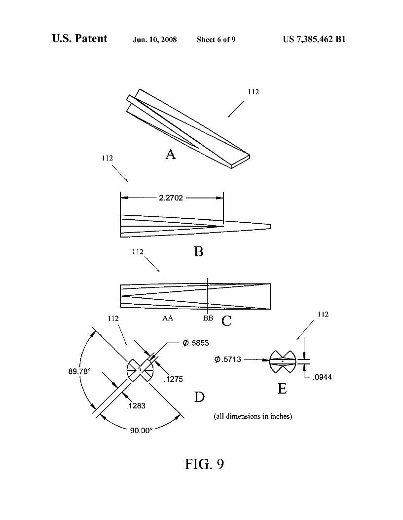
FIG. 9 is a composite illustration showing the outwardly- tapered rectangular waveguide section 112, including a per- spective view (A), a side view (B) with dimensions (inches), top view (C), and two different cross-sections including sec-
25 tion (D) taken along line AA of FIG. 9(C), and section (E) taken along line BB of FIG. 9(C).
FIG. 10 is a composite illustration showing the pyramidal section 114 from various perspectives, including a perspec- tive view (A), a right-end view (B) with both linear and
30 angular dimensions (inches), side view (C), and top view (D). FIGS. 11 and 12 illustrate the requisite test connections for
FIGS. 13 and 14 are graphs of the port matching results.
DETAILED DESCRIPTION OF THE PREFERRED EMBODIMENT
10
2o and right end view (D).
“Output Match” and “Insertion Loss” measurements.
35
The present invention is a radial power divider andor com- 4o biner for dividingicombining a increased number N of ampli-
fier signals within a wide bandwidth using compact radial format. The radial power combineridivider generally com- prises an axially-oriented mode transducer coupled to a radial base. The mode transducer transduces circular TEOl
45 waveguide into rectangular TElO waveguide, and the radial base combinesidivides a plurality ofports intoifrom the single circular TEOl waveguide end of the transducer. The radial base is formed with a plurality of internal waveguides leading from peripheral output ports and converging radially to the
5o center, the internal waveguides incorporating a stepped impedance configuration that allows a reduction in their size and increase in the order N of combining. The base also includes a matching post at the bottom center which matches the reduced height rectangular waveguides into the circular
The invention may be implemented as a power combiner or power divider, or may be combined in a power dividericom- biner.
The combineridivider is herein illustrated in detail in the 60 context of an N=24 combiner for use in Ka-band over the
band of 3 1-36 GHz, with an input match e-20 dB under equal excitation of all input ports, an output match e-24 dB coming out of the mode transducer, and an insertion loss e0.6 dB.
FIG. 1 is a perspective view of an N-way power divideri 65 combiner 2 according to a preferred embodiment of the
present invention which, in this particular example, is tuned for N=24 ports and a 15% 3 1 to 36 GHz bandwidth.
55 waveguide that feeds the mode transducer.
US 7,385,462 B1 5
The power dividericombiner 2 generally comprises a radial base 20 with a plurality N of internal waveguides (here N=24) running axially and internal to the base 20 from peripheral ports 22 (spaced evenly around the base 20) and converging to a matching post (obscured) in the center of base 20. For testing purposes, a plurality of matching loads 30 are shown mounted axially around the base 20 to balance the ports 22 not in use, and each load 30 is coupled to a non-use port 22 by machine-screw attachment to the periphery of the base 20. The base 20 has a topside center output port (obscured) for mounting a mode transducer 10. The mode transducer 10 is a three-section transducer with distal ports 16, 18 that convert the TEOl circular waveguide mode at the center output port of base 20 back into standard rectangular TEOl waveguide mode at transducer port 16.
FIG. 2 is a composite drawing illustrating the radial base 20(A), sectionedalong its widthat (B) and (C), with exploded illustrations at (D) & (E) showing the sectioned internal waveguides 50. The radial base 20(A) is preferably formed in the two sections as shown at (B) & (C) which are secured together by machine screws. The two sections of radial base 20 may be formed from Aluminum, Invar, Copper or other suitable waveguide material. The waveguides 50 are formed partially in the first section (B) of the base 20 and partially in the second section (C) and join when the sections (B) & (C) are joined to form full waveguides leading axially outward to ports 22. The illustrated ports 22 are formed as standard size WR28 rectangular TEOl waveguide ports, though other port sizes may suffice.
As best seen at exploded illustrations (D) & (E) the sec- tioned internal waveguides 50 of the first section (D) are evenly spaced and radially converge toward a central cylin- drical cavity 52 that is formed with a central cylindrical matching post 54 at the center. The matching post 54 pro- trudes upward to a plateau even with the inner surface of the first section. The sectioned internal waveguides 50 of the second section (E) likewise converge to the topside center output port which is formed as a central cylindrical aperture 55 that conforms to the cavity 52. In accordance with the present invention, each axial waveguide 50 (along both sec- tions) is formed with a rectangular cross-section that extends uniformly from ports 22 to one or more constricted steps 56 (three successive steps 56A-C being here illustrated), the steps 56 effectively forming a rectangular stepped-impedance configuration with incremental height changes.
FIG. 3 is a composite diagram showing identical cross- sections (from above) of an axial waveguide 50 with an exem- plary set of dimensions indicated thereon suited for attaining the performance specifications of the illustrated embodiment (bandwidth30-36 GHz, N=24 amplifiers). All dimensions are shown inmils (YIOOO inches). The waveguide 50 begins at 140 mils width to the first step 56A which is constricted by a difference of 22 mils, then continues 113 mils along at 11 8 mils wide to the second step 56B which is constricted by a difference of 34 mils, then continues 11 1.5 mils along at 70 mils wide to the third step 56C which is constricted by a difference of 14 mils. Each step 56A-C is rounded with a 10 mil radius.
In general operation when used as a combiner, rectangular TEOl waveguide signals input to ports 22 form reflections along the walls of the stepped-height waveguides 50 which must be combined properly into a TEOl circular waveguide mode, and this purpose is served by the matching post 54, which provides a circular waveguide output through the top- side center output port (aperture 55) into the mode transducer 10 described below. Thus, the radial base 20 has standard
6 rectangular TElO mode waveguide input and a circular waveguide TEOl mode output at aperture 55.
FIG. 4 is a perspective view of the “Marie” mode trans- ducer 10 of FIG. 1 with circular waveguide (CWG) port 18
5 including a distally attached coupling flange at one end ofthe transducer body 11 and rectangular waveguide port 16 (either WR28 or WR24) at the other end also including a coupling flange. The illustrated circular waveguide port 18 is a stan- dard circular (CWG) port or the like, for example, input size
i o WR28 (circular waveguides are not called out in standards like rectangular waveguides and so the designation “circular waveguide (CWG)” is herein used. In the preferred embodi- ment a circular waveguide was chosen to support the desired circular TEOl mode over the band of interest, and the size is
15 sufficient to combine the 24 inputsioutputs. A cross-section of the mode transducer body 11 is show at
FIG. 5 with exemplary dimensions (in inches). The flange of port 18 is secured to transducer body 11 as shown and is attached directly to the base 20 (via machine screws) for
20 coupling the transducer body 11 thereto to aperture 55 in communication with the cavity 52 (and matching post 54) of base 20.
FIG. 6 is a front view of port 18 with flange, and FIG. 7 is a front view of port 16 with flange. As stated above, in the
25 preferred (illustrated) embodiment port 18 may be a standard circular CWG input size WR28 waveguide port, though other standard port sizes are possible. Port 16 may be either of a WR28 or WR34 rectangular output, though again other stan- dard port sizes are possible.
The transducer body 11 of the mode transducer 10 is designed to convert the radial base 20 circular TEOl waveguide output at aperture 55 back to rectangular TElO waveguide mode. Generally, the transducer body 11 of the mode transducer 10 was designed based on the concept of S.
35 S. Saad, J. B. Davies, and 0. J. Davies, “Analysis and Design of a Circular TEOl Mode Transducer,” Microwave, Optics andacoustics, vol. 1, pp. 58-62, Jan. 1977. Saadet al. therein disclose the concept of a “Marie Mode” transducer for trans- ducing multiple rectangular TElO modes to circular TEOl
40 mode. Multiple TEOl modes are transitioned into an interme- diate mode, which is transitioned into a circular TEOl mode and vice versa. The present transducer employs different symmetry considerations and dimensions.
As seen in FIG. 5, the transducer body 11 includes three 45 distinct sections beginning at the TEOl end (left) with a
tapered cylindrical waveguide section 110 running approxi- mately one-third the length of transducer body 10 and taper- ing inward to transition the multiple TEOl modes from base 20 into an intermediate cylindrical mode. Next, anoutwardly-
50 tapered rectangular waveguide section 112 running approxi- mately one-third the length of transducer body 10 and taper- ing outward to transition the intermediate cylindrical mode to an intermediate rectangular mode. Finally, a pyramidal sec- tion 114 running the last third the length of transducer body
55 10 to transition the intermediate rectangular mode to a rect- angular TEOl mode.
The exact profile, contour and length of each section 110- 114 must be precisely tuned in order to make it possible to combine 24 inputs, operating from 31 to 36 GHz. Conse-
60 quently, FIGS. 8-10 are each composite drawings illustrating the particular profile, contour and length of each of section 1 10 - 11 4, respectively.
Beginning at the TEOl end, FIG. 8 shows the tapered cylindrical waveguide section 110, including a perspective
65 view (A), and a sideview (B) with dimensions (in inches), left end view (C) and right end view (D). The cylindrical waveguide section 110 begins at the left with a full cylindrical
30

US 7,385,462 B1 7 8
cross-section of constant radius, as seen at (C), running ports 22. The signal receiver may be a test device, such as a 0.4724 inches, then beginning a gradual taper to a cross- spectrum analyzer, or a multiple-amplifier module. shaped section at right and as seen at (D). The dimensions By reversing signal direction, the dividericombiner may (inches) and angular disposition of the cross-shaped section function as a combiner. In this case, a plurality N of TEOl are indicated in FIG. 8(D). The cylindrical waveguide section 5 waveguide signals are input at ports 22 (via coaxial cables or 110 tapers inward to transition the multiple TEOl modes from the like) and propagate in through the waveguides 50, which base 20 into an intermediate cylindrical mode. maintain a rectangular cross-section to the constricted steps
The cylindrical waveguide section 110 merges into an out- 56. The steps 56 impart a rectangular stepped-impedance wardly-tapered rectangular waveguide section 112 shown in configuration as a result of their incremental height changes. FIG. 9, which likewise runs approximately one-third the i o The N signals are combined and transitioned by matching length of transducer body 10 and tapers from the cross- post 54 from rectangular TEOl mode to circular TElO mode, shaped section of FIG. 8(D) to a flat waveguide section. and the combined signal is output through port 18 into the
FIG. 9 shows the outwardly-tapered rectangular mode transducer body 11. Inside the transducer body the waveguide section 112, including a perspective view (A), a signal propagates through the tapered cylindrical waveguide sideview (B) with dimensions (inches), top view (C), and two 15 section 110, then through tapered rectangular waveguide sec- different cross-sections including section (D) takenalong line tion 112, and finally through the rectangular waveguide sec- AA of FIG. 9(C), and section (E) taken along line BB of FIG. tion 114 which transitions the intermediate rectangular mode 9(C). The outwardly-tapered rectangular waveguide section to a single rectangular TEOl mode which is output through 112 begins at the left with the cross-shaped section conform- port 16. A prototype N=24 combiner has been constructed for ing to that of FIG. 8(D), the arms of the cross tapering away 20 Ka-band and demonstrated over the band of 3 1-36 GHz with and graduating to the flat waveguide section at right, thereby an input match e-20 dB under equal excitation of all ports 22, converting the intermediate cylindrical mode to an interme- output match e-24 dB at the port in flange 16 of the mode diate rectangular mode. transducer 10, and an insertion loss e0.6 dB. The functional
Finally, FIG. 10 illustrates the pyramidal section 114 that bandwidth of the combineridivider 2 exceeds the initial runs the last third of transducer body 10 to transition the 25 design goal of 31-36 GHz. intermediate rectangular mode to a fully rectangular TEOl Generally, for normal operation all ports 22 will be used. mode. FIG. 10 shows the pyramidal section 114 from various However, for testing purposes only one or two ports 22 will be perspectives, including a perspective view (A), a right-end used, and a plurality of matching loads 30 are shownmounted view (B) with both linear and angular dimensions (inches), axially around the base 20 (FIG. 1) to balance the ports 22 not side view (C), and top view (D). The pyramidal section 114 30 in use. The dividericombiner 2 may be tested using a conven- begins at left conforming to the flat horizontal rectangular tional vector network analyzer (VNA) consisting of a sweep waveguide section 112 at the right of FIG. 9(A), and gradu- oscillator, a test set which includes two ports, a control panel, ating to a flat orthogonal waveguide section at the right of an information display, and coaxial cables to attach to the FIG. lO(A), thereby converting the intermediate rectangular dividericombiner 2. mode to a fully rectangular TEOl mode at output port 16 of 35 FIGS. 11 and 12 illustrate the requisite test connections for FIGS. 5 and 7. “Output Match” and “InsertionLoss” measurements, and
The three above-described sections 110, 112, and 114 are FIGS. 13 and 14, respectively show the port matching results preferably integrally formed in a unitary transducer body 11, on the rectangular waveguide ports 01-12. which is then attached to ports 16,18. In FIG. 11, measurements were competed with the VNA
It is noteworthy that the above-described transducer 10 can 40 portl fixed on port 25 of the dividericombiner 20, VNA port2 easily be designed to provide two different rectangular on ports 01 through 12, the transducer at SIN 2, and Base S N waveguide outputs by modification of only section 114, lead- 2. ing to an alternate design for multiple frequency ranges with FIG. 13 illustrates the port match over the intended band- a common circular waveguide input. width 31-36 GHz, which shows the match e-24 dB over the
In this case a signal generator will provide an input signal to In FIG. 12, measurements were completed with the VNA the divider 2 at the input flange 16 of mode transducer 20 via portl fixed on port 25 of the dividericombiner 20, VNA port2 a coaxial cable attached to the flange 16 via a connector, on ports 01 through 14 (keeping orientation same as above), which may be an SMA connector, for example. Once inside the Transducer at S N 2, and Base at S N 2. the mode transducer 20, the signal propagates down through 50 FIG. 14 illustrates the port match over the intended band- the transducer body 11 through the a pyramidal section 114 width 31-36 GHz, which shows similarly good behavior. The which transitions from rectangular TEOl mode to intermedi- mode transducer insertion loss is calculated by measuring the ate rectangular mode, then through tapered rectangular two transducers SN1 and SN2 back-to-back, and dividing the waveguide section 112 which transitions the intermediate loss by half. The agreement with theory from the design is rectangular mode to an intermediate cylindrical mode, and 55 excellent. For the Mode transducer with the WR34 output finally through the tapered cylindrical waveguide section 110 port there is a good match e-27 dB, and low measured inser- which transitions the intermediate rectangular mode to a tion loss. The input match of each of the other input ports 2 single cylindrical TElO modes which is propagated into base through ports 24 were likewise measured, and the measure- 20. The matching post 54 provides a circular waveguide out- ments indicate the level of repeatability and error to be put from the transducer 10 into a rectangular mode within 60 expected. This combiner has an input match e-20 dB under each axial waveguide 50 in the base 20. The waveguides 50 equal excitation of all input ports, an output match e-24 dB at maintain a rectangular cross-section to the constricted steps the RWG port of the Marie Transducer, and an insertion loss 56 which impart a rectangular stepped-impedance configura- e0.6 dB. The functional bandwidth of the combiner exceeds tion as a result of their incremental height changes. Thus, the initial design band of 31-36 GHz. This excellent perfor- inside the base 20 the signals are effectively divided to form 65 mance demonstrates the potential for this power combiner 2 N output signals (here N=24). One or more of these output to enable a new class of high-power, high-efficiency solid- signals may then be provided to a signal receiver coupled to state amplifiers. It should now be apparent that the above-
For operation of the power dividericombiner 2 as a divider. 45 bandwidth.

US 7,385,462 B1 9 10
described radial power dividericombiner is capable of replac- waveguide section running approximately one-third a length ing tube-based flight and ground amplifiers with solid state of the transducer body, an outwardly-tapered rectangular MMIC-based amplifiers for use in earth-orbiting defense waveguide section running approximately one-third the missions and radar applications, as well as satellite secure length of transducer body, and a pyramidal section running communications systems requiring large bandwidths (secure 5 approximately one third the length of said transducer body. satellite uplinks, downlinks, and cross-links), etc. 7. A radial power dividericombiner comprising: a radial
Having now fully set forth the preferred embodiment and base including a plurality of internal rectangular waveguides certain modifications of the concept underlying the present each converging radially from a periphery of said base to a invention, various other embodiments as well as certain varia- central cavity, the internal rectangular waveguides formed tions and modifications of the embodiments herein shown 10 with a stepped-height configuration comprising a plurality of and described will obviously occur to those skilled in the art spaced constrictions for creating a stepped impedance, and a upon becoming familiar with said underlying concept. It is to port formed as an aperture in said base opening to the central be understood, therefore, that the invention may be practiced cavity; and a mode transducer mounted axially on said base otherwise than as specifically set forth herein. and having a circular waveguide port at one end coupled to the
15 aperture of said base and a rectangular waveguide port at another end.
8, The radial power dividericombiner of claim 7, wherein said radial base further comprises a matching post formed as a truncated cylinder at a center of said central
We claim: 1. A radial power dividericombiner comprising: a radial
base including a plurality of internal rectangular waveguides each converging radially from a Periphery of said base to a central cavity, the internal rectangular waveguides formed with a spaced constrictions for creating a stepped impedance, a
said cavity, and a Port formed as an aperture in said base Opening to the cavity; and a mode transducer
comprising a Plurality Of 2o 9. The radial power dividericombiner of claim 7, wherein the plurality of spaced constrictions further comprises at least
matching post formed as a truncated cylinder at a center of two constrictions, 10, The radial power dividericombiner ofclaim 7, wherein
saidmode transducer further comprises a circular CWG input mounted axially on said base and having a circular waveguide 25 port of standard size coupled to the aperture of said base, port at one end coupled to the aperture of said base and a
11. The radial power dividericombiner of claim 7, wherein rectangular waveguide port at another end. of claim 1, wherein saidmode transducer further comprises any one of a standard
rectangular WR28 or WR34 port at said other end. the plurality of spaced constrictions further comprises at least two constrictions. 12. The radial power dividericombiner of claim 7, wherein
3, ne radial power dividericombiner of claim 1, wherein said mode transducer further comprises a transducer body said mode transducer further comprises a circular CWG input port of standard size coupled to the aperture of said base. 13. The radial power dividericombiner of claim 12,
4. The radial power dividericombiner of claim 1, wherein wherein said three distinct sections include a tapered cylin- saidmode transducer further comprises any one of a standard 35 drical waveguide section running approximately 0ne-thi1-d a rectangular WR28 or WR34 port at said other end. length of the transducer body, an outwardly-tapered rectan-
5. The radial power dividericombiner of claim 1, wherein gularwaveguide section running approximately one-thirdthe said mode transducer further comprises a transducer body length of transducer body, and a Pyramidal section running including three distinct sections. approximately one third the length of said transducer body.
2, The radial power
3o
three distinct sections.
6. The radial power dividericombiner of claim 5, wherein 40 said three distinct sections include a tapered cylindrical * * * * *