United States Patent Patent Number: 5,186,806 Date of 16, 1993 - … · 5.186.806 3 able that the...
16
1111 l l 111 l l 11111111 l l 1111111111111111111111111111111 IIIII I I 1 I I I I I l 111111111 United States Patent t191 Clark et al. [54] CERAMIC DISTRIBUTION MEMBERS FOR SOLID STATE ELECTROLYTE CELLS AND METHOD OF PRODUCING [75] Inventors: Douglas J. Clark, Ontario; Leo M. Galica, Mira Loma; Robert W. Losey, Lancaster; Jerry W. Suitor, El Toro, all of Calif. [73] Assignee: California Institute of Technology, Pasadena, Calif. [21] Appl. No.: 636,484 [22] Filed: Dee. 31, 1990 [51] Int. (3.5 ................................................ C25B 9/00 [52] U.S. Cl. .................................... 204/265; 204/266; 204/258; 204/260; 204/426; 204/429; 204/424; 429/30; 429/32 [58] Field of Search ............... 204/424, 425, 426, 427, 204/428,429, 265,266, 247, 258, 260, 59 R; 423/219; 429/30, 32 t561 References Cited U.S. PATENT DOCUMENTS 4,344,832 8/1982 Dahlberg ............................ 204/258 4,426,261 1/1984 Fushihara ............................ 204/260 4,857,420 8/1989 Maricle et al. ........................ 429/30 4,885,142 12/1989 Suitor et al. ........................ 423/219 4,951,673 9/1990 Schroeder et al. ................... 264/60 US005186806A [ii] Patent Number: . 5,186,806 [45] Date of Patent: Feb. 16, 1993 OTHER PUBLICATIONS Proceedings of the 23rd Intersociety Energy Conver- sion Conference, vol. 2, ASME, New York, 1988, pp. 273-277, by Suitor et al. Primary Examiner-John Niebling Assistant Examiner-Kathryn Gorgos Attorney, Agent, or Firm-F. Eugene Logan WI ABSTRACT A solid state electrolyte cells apparatus and method of producing is disclosed. The apparatus can be used for separating oxygen from an oxygen-containing feedstock or as a fuel cell for reacting fluids. Cells can be stacked so that fluids can be introduced and removed from the apparatus through ceramic distribution members having ports designed for distributing the fluids in parallel flow to and from each cell. The distribution members can also serve as electrodes to membranes or as membrane members between electrodes. The distribution member design does not contain any horizontal internal ports which allows the member to be thin. A method of tape casting in combination with an embossing method al- lows intricate radial ribs and bosses to be formed on each distribution member. The bosses serve as seals for the ports and allow the distribution members to be made without any horizontal internal ports. 49 Claims, 3 Drawing Sheets https://ntrs.nasa.gov/search.jsp?R=20080004288 2019-07-12T05:38:49+00:00Z
Transcript of United States Patent Patent Number: 5,186,806 Date of 16, 1993 - … · 5.186.806 3 able that the...

1111ll111ll11111111ll1111111111111111111111111111111 IIIII II1IIIIIl111111111 United States Patent t191
Clark et al.
[54] CERAMIC DISTRIBUTION MEMBERS FOR SOLID STATE ELECTROLYTE CELLS AND METHOD OF PRODUCING
[75] Inventors: Douglas J. Clark, Ontario; Leo M. Galica, Mira Loma; Robert W. Losey, Lancaster; Jerry W. Suitor, El Toro, all of Calif.
[73] Assignee: California Institute of Technology, Pasadena, Calif.
[21] Appl. No.: 636,484
[22] Filed: Dee. 31, 1990
[51] Int. ( 3 . 5 ................................................ C25B 9/00 [52] U.S. Cl. .................................... 204/265; 204/266;
204/258; 204/260; 204/426; 204/429; 204/424; 429/30; 429/32
[58] Field of Search ............... 204/424, 425, 426, 427, 204/428,429, 265,266, 247, 258, 260, 59 R;
423/219; 429/30, 32
t561 References Cited U.S. PATENT DOCUMENTS
4,344,832 8/1982 Dahlberg ............................ 204/258 4,426,261 1/1984 Fushihara ............................ 204/260 4,857,420 8/1989 Maricle et al. ........................ 429/30 4,885,142 12/1989 Suitor et al. ........................ 423/219 4,951,673 9/1990 Schroeder et al. ................... 264/60
US005186806A [ i i ] Patent Number: . 5,186,806 [45] Date of Patent: Feb. 16, 1993
OTHER PUBLICATIONS Proceedings of the 23rd Intersociety Energy Conver- sion Conference, vol. 2, ASME, New York, 1988, pp. 273-277, by Suitor et al.
Primary Examiner-John Niebling Assistant Examiner-Kathryn Gorgos Attorney, Agent, or Firm-F. Eugene Logan
WI ABSTRACT A solid state electrolyte cells apparatus and method of producing is disclosed. The apparatus can be used for separating oxygen from an oxygen-containing feedstock or as a fuel cell for reacting fluids. Cells can be stacked so that fluids can be introduced and removed from the apparatus through ceramic distribution members having ports designed for distributing the fluids in parallel flow to and from each cell. The distribution members can also serve as electrodes to membranes or as membrane members between electrodes. The distribution member design does not contain any horizontal internal ports which allows the member to be thin. A method of tape casting in combination with an embossing method al- lows intricate radial ribs and bosses to be formed on each distribution member. The bosses serve as seals for the ports and allow the distribution members to be made without any horizontal internal ports.
49 Claims, 3 Drawing Sheets
https://ntrs.nasa.gov/search.jsp?R=20080004288 2019-07-12T05:38:49+00:00Z

U.S. Patent Feb. 16, 1993 I Sheet 1 of 3 5,186,806

US. Patent Feb. 16, 1993 Sheet 2 of 3 5,186,806
74
FIG. 3

U.S. Patent Feb. 16, 1993 Sheet 3 of 3 5,186,806
06
68-
FIG. 4

5,186,806 . 1 2
Methods of producing improved solid ceramic mem- CERAMIC DISTRIBUTION MEMBERS FOR branes useful for transporting ions are disclosed in U.S. SOLID STATE ELECTROLYTE CELLS AND Pat. No. 4,957,673, which is hereby incorporated herein
METHOD OF PRODUCING by reference. This patent discloses a method of produc- 5 ing a solid ceramic electrolyte material having a high
ORIGIN OF INVENTION density electrolyte sandwiched between layers of solid ceramic electrode material having a low density porous The invention described herein was made in the per- structure. One embodiment comprises a sintered central formance of work under a NASA Contract, and is sub- of fitria stabilized zirconia cbysz,) having 95%
202) in which the Contractor has elected to retain title. yttria, and sintered outer ofstrontiumdoped lan- BACKGROUND OF THE INVENTION thanum manganite (“LSM”) having interconnected
porosity and density of 50 to 60% of theoretical with This invention pertains to solid state electrolyte cells the approximate composition Lao,sSro,2Mn03. The for use in fluid separation devices and fuel cells. Fluid LSMNSZ/LSM sandwich structure permits the flow separation devices and fuel cells utilize solid oxide ce- of air through the frst layer of porous LSM. Oxygen is rarnic materials as ionic electrolytes or membranes for then ionized and the oxygen ions are transported transporting jons Of certain substances thereby through the central Y S Z layer. At the other outer layer electrical current to flow through such apparatuses. of porous LSM, oxygen ions recombine and release When such apparatuses are used as fluid %paration 20 electrons. The interconnected porous structure of the devices a fluid, for example air, is introduced to one side LSM layers permits the flow of gases to and from the of the solid ceramic membrane across which an electri- interface of the Y S ~ - t o - L ~ ~ layers. ne membranes
ject to the provisions Of Law 96-517 (35 10 or theoretical density and about 8 mole percent
cal potential has been and oxygen jons are On the opposite side of membrane, the oxygen ions 25
The Oxygen is ionized through the membrane.
disclo& in U.S. Pat. No. 4,957,673 are especially useful in the cells of the invention described hereinafter.
A distribution plate made from A-lava without radi- recombine to form gaseous oxygen and free electrons. ally extending internal ports is disclosed in an article When such apparatuses are used as fuel cells, a fluid entitled OXYGEN SEPARATION FROM AIR reactant, for example hydrogen, is introduced to one USING ZIRCONIA SOLID ELECTROLYTE side of the solid ceramic membrane and another fluid MEMBRANES, proceedings of the 23rd Intersociety
other side of the membrane. The oxygen is ionized and York, 1988, pp. 273-277. ne thickness of the &lava Oxygen jons are transported through the membrane distribution plates was relatively large compared to the whereupon the oxygen ions react with the hydrogen thickness of the membrane disks. Thick distribution forming H2O and releasing electrons thereby generat- plates are a disadvantage if thin electrolyte cells are ing an electrical potential and current. 35 required or desired. Reference is also made to a ribbed
Examples of fluid separation devices utilizing solid design that contacts the electrode surface for current ceramic membranes are disclosed in U.S. Pat. NO. flow, that provides support for the thin zirconia mem- 4,885,142, which is hereby incorporated herein by refer- brane, and that directs the gas flow from the outer cir- ence. This patent discloses several devices for =parat- cumference to the Center of the disk. The ribbed distri- ing oxygen from air in which air distributed at the pe- 40 bution plates also contained horizontal internal ports for riPherY of a disk of Solid ceramic membrane, flows flowing air, oxygen, and oxygen-depleted air in and out radially inwardly over the disk as oxygen ions are trans- of the separation chamber. Unless otherwise specified ported through the membrane disk. Air having a re- “horizontal” means parallel to the plane of the member, duced oxygen content is removed along the axis of the a d “vertical” means perpendicular to the plane of the. membrane disk. Stacks of cells are used to improve the 45 member. BY the term “horizontal internal port” as used separation of oxygen from air. In one stack of cells herein is meant a port entirely within the member and arrangement, alternating membrane disks and ceramic parallel to the plane of the member. distribution plates are used. The ceramic distribution To minimize the overall height and resistance of ap- plates have radially extending internal ports for distrib- paratuses employing stacks of cells, there is a need to uting air from the periphery of the membrane disk radi- SO reduce the thickness of all disk members and particu- ally inwardly towards the axis. In this arrangement, the larly members containing ribs or horizontal internal electrical current is distributed circumferentially ports. Since low temperature electrodes with ribs can be around the edge of the membrane disk by a platinum made of metals, the electrodes can be made very thin. wire contact ring and electrons flow radially inwardly. However, where the apparatus is required to operate at Unfortunately, it has been found that the construction 55 very high temperatures, as is the case for many %para- of distribution plates having radially extending or hori- tors and fuel cells, such high temperatures are generally zontal internal ports which are completely internal of beyond the useful temperature range for metals. Al- the distribution plate is very diflicult especially if thin though platinum can be used at high temperatures, its distribution plates are required or desired. In another cost essentially precludes its use evm if applied in only stack of cells arrangement, the membrane disks are 60 a thin layer. In high temperature cells, both the elec- separated by layers of porous packing material made trode members and the membrane members are gener- from particles of electrically conductive ceramics such ally made from ceramic materials. Thus, there is a need as strontiumdoped lanthanum manganite. In this ar- for a process for producing thin members from ceramic rangement, electrical current flows axially through the materials. membrane disk. Unfortunately, the layers of packing 65 What is needed is a thin distribution plate made from ceramic material increase the electrical resistance, a solid ceramic electrode material which is suitable for weight and height of the apparatus which is not desir- use in an electrolyte cell and which will support an able. electrolyte membrane in a stack of cells. It is also desir-
reactant, for example air or oxygen, is introduced to the 30 Energy Conversion Conference, Val. 2, ASME, New

5.186.806 3
able that the distribution plate provide for parallel port- ing of fluids to and from the cells and for serial flow of electrical current axially through each cell. Since inter- nal horizontal passageways completely within a distri- bution plate tend to weaken it and cause it to break or fail at such passageways, it is also desirable that the distribution plate not contain any internal horizontal passageways.
SUMMARY OF THE INVENTION It is known that zirconia electrolytes will selectively
transport oxygen ions at elevated temperatures and that electrolyte cells containing such zirconia electrolytes will separate oxygen from air or other oxygencontain- ing gases. In such applications, the cell can comprise a three-layer membrane or sandwich, in which an zirco- nia electrolyte membrane is sandwiched between two porous, electrically conductive ceramic electrodes such as those disclosed in U.S. Pat. No. 4,957,673. In U.S. Pat. No. 4,957,673, the porous electrode material is strontium-doped lanthanum manganite which is an elec- trically conductive solid ceramic and the zirconia elec- trolyte membrane is yttria stabilized zirconia. These ceramics form a LSM/YSZ/LSM sandwich or mem- brane member. When electrical current is supplied to the cell, oxygen is selectively transported through the membrane. In operation, the input gas stream, for exam- ple, air, is passed across one side of the cell and pure oxygen is collected from the other side. To avoid con- tamination of the output oxygen, input gas is prevented from leaking to the output side of the cell and to the atmosphere by seals. In U.S. Pat. No. 4,885,142, the membrane is circular or disk shaped, and the input gas stream is directed radially inward from the rim or pe- riphery of the membrane to the center or axis of the circular sandwich. When an electrical current is applied to the cell, oxygen ions are transported through the membrane. Electrical current is supplied to the mem- brane by electrodes. In one configuration, the elec- trodes were platinum wire rings attached to the periph- ery of the membrane sandwich, and in another configu- ration, the electrodes were flat plates spaced away from the membranes by an electrically conductive packing material.
Because of the difficulty of fabricating large-diameter ceramic membranes, it is necessary to use multiple cells to increase the oxygen input to practicd levels. Electri- cal considerations dictate that multiple cells be con- nected in series. The natural configuration for a multi- ple cell unit is therefore a stack. Configurations of stack of cells are disclosed in U.S. Pat. No. 4,885,142. Gas distribution in a single cell is straightforward and does
4 the horizontal internal ports. Because of the high oper- ating temperature required for oxygen separation sys- tems, the distribution plates were constructed of LSM and fired to nearly full density so that they would be
5 impervious to gas flow. The LSM distribution plates were constructed by slip casting in plaster molds. Wax inserts were placed into the mold before casting to create the horizontal internal ports. The horizontal internal ports were radially oriented. Unfortunately
10 considerable difficulty was encountered with this method of producing the distribution plates. The fired plates were often cracked. Cracking occurred fre- quently along the horizontal internal ports. These distri- bution plates also had a tendency to warp during firing
15 because of their relatively large thickness which was necessary to accommodate the horizontal internal ports. Both the scrap rate and fabrication time per distribution plate for this fabrication method were very high. The relatively large thickness of the distribution plate manu-
20 factured by slip casting resulted a stack of cells which required a considerable amount of material, and was physically large and heavy. Because of the aforemen- tioned serious problems, the design of the distribution plates featuring horizontal internal ports and the slip
25 casting method of producing the distribution plates, a need exists for an improved distribution means and method of manufacture.
There is a need, therefore, for a distribution member which does not require horizontal internal ports. It was
30 also desirable to make the distribution member an inte- gral part of either the impervious electrode spacers used to separate the membrane sandwiches, or an integral part of the membrane sandwich, or an integral part of both the impervious electrodes and the electrolyte
35 membrane sandwiches so that either the impervious electrode spacers or the membrane sandwiches or both would serve as means for distributing and directing the flow of the various gas streams.
Non-limiting examples of solid ceramic materials 40 useful for forming electrodes are lanthanum chromates,
strontium lanthanum manganites especially strontium- doped lanthanum manganites having an elemental ratio of about La0.gSro.zMnO3, and other conductive ceram- ics.
The above mentioned problems were resolved in this invention by a novel distribution member design and method of producing. To start, thin tapes of LSM were cast by the tape casting method of U.S. Pat. No. 4,957,673 and circular wafers were then cut from the
50 tape. In particular, the ceramic powder was suspended in a plastic binder solution. A tape casting machine was used to cast long, thin tapes, each about four inches
45
not present a problem. However, 6 a multicell stack of wide. After allowing the solvent to evaporate, circular cells, gas distribution becomes more difficult because wafers were cut from these tapes in the manner de- while the electrical connections must be made in series, 55 scribed in U.S. Pat. No. 4,957,673. It was found that the the gas connections must be made in parallel. green wafers could be pressed between machined dies
Methods to introduce and remove gas from a stack of that contained a predetermined surface configuration. cells is disclosed in U.S. Pat. No. 4,885,142 and the More particularly, the macliined dies were used to em- aforementioned ASME article. Distribution plates were bossed a predetermined pattern of ribs and bosses onto used to separate the individual cells in the stack and 60 the unfired green wafer. The wafers were then fired in provide the parallel gas and series current connections. the normal manner to produce an impervious LSM disk The three gas streams, i.e. input air, depleted air, and containing the desired pattern of ribs and bosses. The oxygen, flow through a distribution plate located be- configuration of the ribbed and bossed LSM disks of tween membranes. The distribution plates disclosed in this invention eliminated the problems associated with these two references required a minimum of three hori- 65 the earlier distribution plates having horizontal internal zontal internal ports inside the body of the distribution ports. Elimination of the horizontal internal ports re- plates for the three streams. A relatively large thickness duced the rate of rejection of distribution members due is required for the distribution plates to accommodate to cracking and warping.

5 5,186,806
6 In this invention, gas streams are introduced and electrode member to the membrane means, ionic cur-
removed from the cells through vertical ports which rent through the membrane means and electrical cur- are parallel to the axis of the cell. Electrical current is rent from the membrane means to the second electrode supplied to the membrane sandwich by ribs which also member while preventing the short circuiting of electri- direct the gas flow in a desired manner. The ribs can be 5 cal current around the membrane means. an integral part of the membrane or LSM/YSZ/LSM A plurality of ribs is provided on the first surface of sandwich or part of a member which abuts the mem- either the membrane means or the first electrode mem- brane or LSM/YSZ/LSM sandwich. In one embodi- ber. The ribs, when abutted against an adjacent mem- ment, the impervious electrode members also serve as ber, form passageways sometimes referred to herein as the means for distributing and directing the fluid flows. 10 first passageways. A plurality of ribs is also provided on In this invention, gases communicate with the mem- the second surface of either the membrane means or the brane through passageways formed by the ribs and second electrode member which, when abutted against bosses on the surface of the distribution members with- an adjacent member, also form passageways, sometimes out the need for horizontal internal ports inside the referred to herein as second passageways. The appara- body of the distribution members. The bosses form seals 15 tus includes first port means in communication with the between the electrode/distribution members and the first passageways, second port means in communication membrane members and form isolated passageways with the first passageways, and third port means in intended for the streams. Air enters a manifold compris- communication with the second passageways. The first, ing a plurality of ports nears the periphery of the distri- the second and the third port means extend through the bution member. The oxygen-depleted air is vented 20 disk shaped member in a direction perpendicular to the through a port in the center of the membrane and re- first surface. moved from the cell through a manifold comprising the In one embodiment of this invention, the first and center port. Oxygen is removed through a manifold second electrode members and the membrane means are comprising another plurality of ports near the periphery wafer shaped. In another embodiment, the first and of the distribution member. 25 second electrode members and the membrane means are
With the elimination of the horizontal internal ports, disk shaped. In a further embodiment, the first and sec- the portion of the cell thickness required for distribution ond electrode members and the membrane means are and direction of the gases was reduced to less than 10% disk shaped and are concentrically aligned. In still an- of the thickness of the earlier mentioned distribution other embodiment, the ratio of the length or diameter of plates of U.S. Pat. No. 4,885,142 and the aforemen- 30 the membrane to the thickness thereof is from about 50 tioned ASME article. This reduction in thickness makes to about 300. it possible to fabricate the fluid distribution component In another embodiment, the first and second elec- using a method of tape casting of U.S. Pat. No. trode members are constructed from electrically con- 4,957,673 in combination with an embossing procedure ductive solid ceramic material. In a further embodi- of this invention. This tape casting/embossing process is 35 ment, the first and second electrode members are more suitable for mass production than the of slip cast- formed by tape casting an electrically conductive solid ing method used in making the distribution plates in ceramic material. In yet another embodiment, the mem- U.S. Pat. No. 4,885,142 the aforementioned ASME brane means is formed by tape casting. article. The fabrication process of this invention also In one embodiment, the plurality of ribs is provided allows a much more intricate pattern or ribs and bosses 40 on the first and second electrode members. In another to be created on the distribution member thereby facili- embodiment, the plurality of ribs is provided on the tating improved gas-to-surface contact with the mem- membrane means. In yet another embodiment, the ribs branes and more uniform distribution of electrical cur- are on one side only of the membrane means and on one rent perpendicular to the membrane. These improve- side only of the electrode members. ments combine to improve overall cell efficiency. It is 45 In still another embodiment, the first and second to be noted that the platinum rings and surface coatings electrode members and the membrane means are disk required in the cells of U.S. Pat. No. 4.957,673 and the shaped, and the ribs on the first surface are radially aforementioned ASME article are not required in this extended. In yet another embodiment, the first and invention. second electrode members and the membrane means are
Accordingly, there is provided by the principles of 50 disk shaped and the ribs on both the first and the second this invention an apparatus for producing a fluid prod- surfaces are radially extended. uct from a fluid feedstock comprising a first electrode In one embodiment, the fvst and second electrode member having a first surface which is impervious to members and the membrane means are disk shaped and fluid flow, and a second electrode member having a are concentrically aligned, and the first port means is second surface which is impervious to fluid flow. The 55 proximate the periphery of the disk shaped members apparatus also includes membrane means comprising a and the second port means is proximate the axis of the solid ceramic electrolyte, located between the first sur- disk shaped members. In a further embodiment, the face of the first electrode member and the second sur- - third port means is proximate the axis of the disk shaped face of the second electrode member. The solid ceramic members. electrolyte material is operable for transporting fluid 60 In one embodiment of this invention, the first and ions therethrough. The membrane means also comprises second electrode members and the membrane means a first surface on one side thereof and a second surface have a thickness from about 0.05 mm to about 1.5 mm. on the opposite side thereof, the first surface of the In another embodiment, the ribs are raised from the first membrane means facing the first surface of the first surface and the second surface a distance of from about electrode member and the second surface of the mem- 65 0.05 mm to about 1.5 mm and have a width of from brane means facing the second surface of the second about 0.05 mm to about 1.5 mm. electrode member. The membrane means is designed so The first and second electrode members and the that it allows the flow of electrical current from the first membrane means form a cell. In one embodiment, the

7 5,186,806
apparatus comprises a plurality of cells arranged to form a stack of cells. In another embodiment, at least one of the electrode members in the stack of cells has said first surface on one side thereof and said second surface on the opposite side thereof thereby enabling 5 such member to serves as the first electrode member of one cell and the second electrode member of the adja- cent cell in the stack of cells.
In a further embodiment of this invention, there is also provided contact means for maintaining physical 10 and electrical contact between the ribs and the elec- trode member or membrane means adjacent thereto. When the apparatus is in use, electrical current will flow parallel to the axis of the electrode members. Fluid introduced into the first port means or second port l5 means will flow into the radial first passageways. When used as a separator, fluid ions, having flowed through the membrane means, will flow from the second pas- sageways to the third port means. When used as a fuel cell, reactant flowing into the first port means will flow into the first passageways and fluid ions will flow through the membrane means to the second surface thereof.
ond port means is connected to means for introducing
20
In yet another further embodiment, the first or sec- 25
fluid-feedstock into the first passageways, and the other one of the first or second port means is connected to means for removing spent feedstock from the first pas- sageways. In a separator embodiment, the third port means is connected to means for removing fluid product separated by the membrane means. In a fuel cell em- bodiment, the first or second port means is connected to means for introducing fluid feedstock into the first pas- sageways for ionizing and transport through the mem- brane means for reaction with fluid in the second pas- sageways.
There is also provided by the principles of this inven- tion a disk shaped member for a cell comprising a main body portion having a first surface on one side and a second surface on the opposite side, and having a pe- ripheral boss extending perpendicularly from the first surface for forming a seal around the perimeter of the first surface. The disk shaped member also comprises a first port extending through the disk shaped member from the first surface to the second surface, a second port extending through the disk shaped member from the first surface to the second surface, and a third port extending through the disk shaped member from the first surface to the second surface, the first, second and third ports being spaced away from each other and radially inward of the peripheral boss. The disk shaped member also has a boss, sometimes referred to herein as the third port boss, extending perpendicularly from the first surface and forming a seal around the third port on the first surface, and a plurality of ribs extending per- pendicularly from the first surface, the plurality of ribs for forming passageways on the first surface. In one embodiment, the first port is proximate the peripheral boss. In another embodiment, the second port is proxi- mate the axis of the disk shaped member. In still another embodiment, the ribs are radially extending from proxi- mate the second port to proximate the peripheral boss and form radially extending passageways on the first surface. In one embodiment, the third port is proximate the peripheral boss. In another embodiment, the disk shaped member has a second port boss extending per- pendicularly from the first surface and proximate the
30
35
40
45
50
55
60
65
8 second port for forming a seal around the second port on the first surface.
In one embodiment, the disk shaped member further comprises a first peripheral boss extending perpendicu- larly from the first surface for forming a seal around the perimeter of the first surface, and a second peripheral boss extending perpendicularly from the second surface for forming a seal around the perimeter of the second surface. The disk shaped member also has a first port extending through the disk shaped member from the first surface to the second surface, a second port extend- ing through the disk shaped member from the first sur- face to the second surface, and a third port extending through the disk shaped member from the first surface to the second surface, the first, second and third ports being spaced away from each other and inward of the first peripheral boss and second peripheral boss. In addi- tion to the third port boss, in this embodiment, the disk shaped member also has a second port boss extending perpendicularly from the second surface and proximate the second port for forming a seal around the second port on the second surface, and a first port boss extend- ing perpendicularly from the second surface for form- ing a seal around the first port on the second surface. When the member is abutted against an adjacent mem- ber in the formation of a cell, the ports are isolated from the surface containing their bosses.
In addition to the ribs on the first surface, in this embodiment, the disk shaped member further comprises a plurality of ribs extending perpendicularly from the second surface. When the rib-containing member is abutted between adjacent members in the formation of a cell, the plurality of ribs form first passageways on the first surface, and second passageways on the second surface. The ribs also serve as structural support and spacers between members. In another embodiment the plurality of ribs on the first and/or second surface radi- ally extend from proximate the axis to proximate the peripheral boss and form radially extending passage- ways on the surface. In one embodiment, the disk shaped member is an electrode and the first and second surfaces thereon are impervious to fluid flow. In an- other electrode embodiment, the disk shaped member is formed from a solid ceramic material that is electrically conductive and the first and second surfaces are made impervious to fluid flow. In one embodiment, the sur- faces are made impervious to fluid flow by forming the electrode members from a high density tape.
In another embodiment, the disk shaped member comprises a solid ceramic material that is operable as a membrane material, and the fmt and second surfaces are pervious to fluid product ion flow.
In another embodiment, the disk shaped member has a thickness from about 0.05 mm to about 1.5 mm, the bosses and the ribs extend from the first surface apd the second surface a distance of from about 0.05 mm to about 1.5 mm, the ribs have a width of from about 0.05 mm to about 1.5 mm, and the bosses have a width of at least about 0.05 mm.
There is also provided by the principles of this inven- tion a method for forming a ribbed member for a cell comprising tape casting a slip from a slurry of particu- late solid ceramic material thereby forming a green tape, embossing a plurality of ribs arranged in a prede- termined pattern on the green tape thereby forming an embossed green tape, and firing the embossed green tape to form a ribbed member for a cell. In one embodi- ment, the embossing is performed on one side of the

5,186,806 9
green tape, and in another embodiment, the embossing is performed on both sides of the green tape. In still another embodiment, the member is cut from the green tape so that the member has a disk shape and the ribs are embossed on the green disk shaped member so that the ribs are radially extended. In yet another embodiment, the ribs are embossed on oneside only of the membrane means and embossed on one side only of the electrode members. In a still further embodiment, the ribs are embossed so that after firing the ribs have a height of from about 0.05 mm to about 1.5 mm and a width of from about 0.05 mm to about 1.5 mm. In another em- bodiment, the bosses are embossed so that after firing the bosses have a height of from about 0.05 mm to about 1.5 mm and a width of at least about 0.05 mm.
In one embodiment, the particulate solid ceramic material is, when fired, an electrically conductive ce- ramic, and the ribbed member formed serves as an elec- trode member in a cell. In another embodiment, the particulate solid ceramic material is operable, when fired, for transporting fluid ions, and the ribbed member formed serves as a membrane member in a cell.
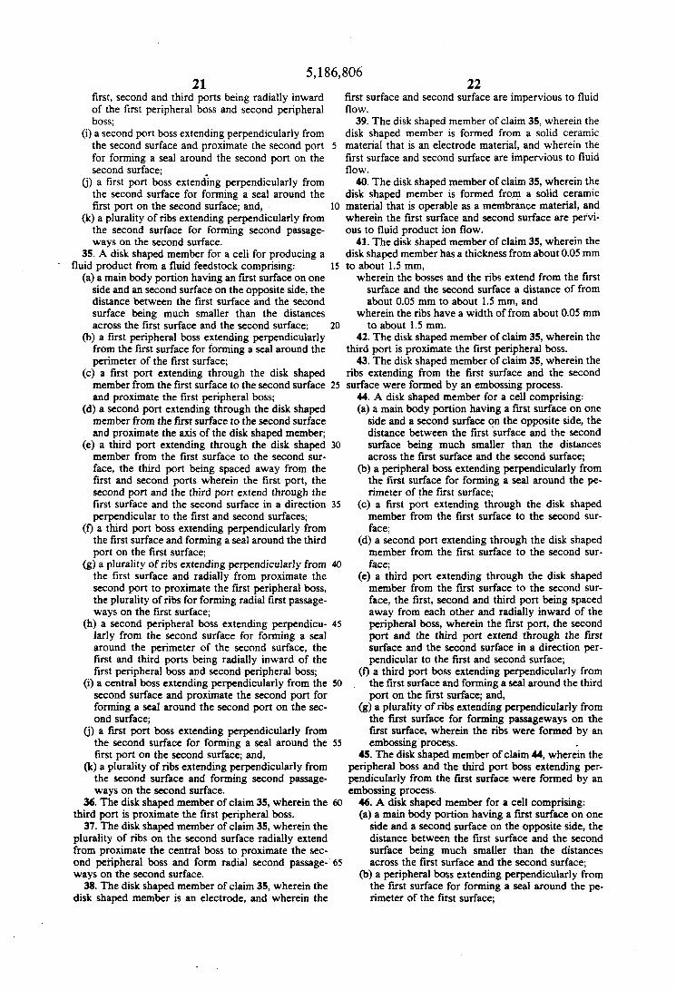
BRIEF DESCRIPTION OF THE DRAWINGS FIG. 1 is a top view of a ribbed disk shaped member. FIG. 2 is an enlarged cross-sectional view of a por-
tion of a stack of cells taken in the direction of line 2-2 of FIG. 1.
FIG. 3 is a top view of another ribbed disk shaped member.
FIG. 4 is a bottom view of the ribbed disk shaped member of FIG. 3.
DESCRIPTION OF THE PREFERRED EMBODIMENTS
FIGS. 1 and 2 illustrate the principles of this inven- tion adapted to a ribbed disk shaped member generally designated by numeral 10. FIG. 1 is a top view of the ribbed disk shaped member 10 having main body por- tion 12, axis 14 (shown in FIG. t), radially extending top surface 16 sometimes referred to herein as the first surface, four peripheral ports 18 sometimes referred to herein as the first ports, a central port 20 sometimes referred to herein as the second port, and four periph- eral ports 22 sometimes referred to herein as the third ports. Top surface 16 also comprises upper peripheral boss 24 which, when assembled as a cell as shown in FIG. 2, acts as a seal isolating the top surface there- within. Each third port has a boss 26, sometimes re- ferred to herein as the third port boss, which surrounds the third port and, when assembled as a cell, acts as a seal isolating the third port therewithin. Top surface 16 also comprises a plurality of radially extending upper ribs 28. FIGS. 1 and 2 show that upper peripheral boss 24 encloses the first, second and third ports and the upper ribs.
FIG. 2 is an enlarged cross-sectional view of a por- tion of a stack of cells, generally designated by numeral 30, taken in the direction of line 2-2 of FIG. 1. The stack of cells 30 comprises ribbed disk shaped members 10 and flat plate members 32 stacked concentrically to axis 14 in alternating order. As seen in FIG. 2, each ribbed disk shaped member 10 is aligned along axis 14 and has first surface 16 and bottom surface 34 some- times referred to herein as the second surface. Ports 18, 20 and 22 extend axially through member 10.
First surface 16 comprises upper peripheral boss 24, third port bosses 26, and upper radially extending ribs
5
10
15
20
25
30
35
40
45
50
55
60
65
10 28. Second surface 34 comprises.lower peripheral boss 36 which, when assembled as a cell, acts as a seal isolat- ing the lower surface therewithin. Second surface 34 also comprises bosses 38, sometimes referred to herein as the first port boss, which surrounds each of first ports 18 and, when assembled as a cell, acts as a seal isolating each of the first ports therewithin. Second surface 34 also has a boss 40, sometimes referred to herein as the central or second port boss, which surrounds the second port and, when assembled as a cell, acts as a seal isolat- ing the second port therewithin. Second surface 34, therefore, comprises lower peripheral boss 36, first port bosses 38, second port boss 40, and radially extending lower ribs 42.
FIG. 2 shows that each ribbed disk shaped member 10 has four parallel planes, namely the plane of the first surface 16, the plane of the second surface 34, the plane of the raised surface of the upper peripheral boss 24, and the plane of the raised surface of the lower peripheral boss 36. The plane of the raised surface of the upper peripheral boss 24 also includes the raised surfaces of the upper ribs 28 and the third port bosses 26. The plane of the raised surface of the lower peripheral boss 36 also includes the raised surfaces of the lower ribs 42, the first port bosses 38, and the second port boss 40.
As shown in FIG. 2, ribbed disk shaped members 10 are abutted between flat plate members 32. Each flat plate member 32 has a first surface 44 and a second surface 46 such that, when assembled as a cell, the first surface 44 faces the first surface 16 of ribbed disk shaped member 10, and, the second surface 46 faces the second surface 34 of member 10. Each flat plate member also comprises four peripheral ports 48 which are in axial alignment with the four ports 18 of member 10, respec- tively, a central port 50 which is in axial alignment with port 20, and four peripheral ports 52 which are in axial alignment with the four ports 22, respectively.
Referring to FIG. 2, it can be seen that the four first ports 48 of flat plate members 32 and the four first ports 18 of ribbed disk shaped members 10 are in fluid com- munication with each other; that the second ports 50 of flat plate members 32 and the second ports 20 of ribbed disk shaped members 10 are in fluid communication with each other; and, that the four third ports 52 of flat plate members 32 and the four third ports 22 of ribbed disk shaped members 10 are in fluid communication with each other. It can also be Seen that the upper ribs 28 form radial passageways between first surfaces 44 of flat plate members and first surfaces 16 of ribbed disk shaped members 10; and, that lower ribs 42 form radial passageways between second surfaces 34 of member 10 and second surfaces 46 of flat plate members 32.
If the apparatus is operated as a separator then fluid feedstock entering the manifold formed by ports 48 of flat plate members 32 and ports 18 of ribbed member 10 will flow radially between first surfaces 16 and 44 towards axis 14 and exit through the manifold formed by ports 50 of flat plate members 32 and ports 20 of ribbed members 10. If either members 10 or 32 are per- vious to ion flow of a component of the fluid feedstock, then such component ions will flow through such pervi- ous members and into the radial passageways formed by lower ribs 42. The separated product can be removed from the apparatus through the manifold formed by third ports 52 in flat plate members 32 and ports 22 in ribbed member 10.
Similarly, if the apparatus is operated as a fuel cell, then a first fluid feedstock entering the manifold formed

5,186,806 11
by ports 18 and 48, or alternatively the manifold formed by ports 20 and 50, of members 10 and 32, respectively, will flow radially between first surfaces 16 and 44. If either members 10 or 32 are pervious to ion flow of the first fluid feedstock, then such first fluid feedstock ions will flow through first surfaces 44 or 16 and through such pervious members whereupon the first fluid feed- stock can react in the passageways formed by the lower ribs 42 with a second fluid feedstock introduced into the manifold formed by one half of ports 22 and 52, for example ports 22 appearing at the top-left and bottom- right of FIG. 1. The resulting reaction product and excess second fluid feedstock is removed through the manifold formed by the other half of ports 22 and 52, for example ports 22 appearing at the top-right and bottom- left of FIG. 1. The excess first fluid feedstock is re- moved from the apparatus through the manifold formed by ports 20 and 50, or alternatively ports 18 and 48.
FIGS. 1 and 2 show the general features of the ribbed disk shaped member 10 used in stack of cells 30 and how the various streams are introduced and removed from the apparatus when it is used as a separator or as a fuel cell. It is to be understood that either ribbed disk shaped member 10 or flat plate members 32 will be pervious to ion flow.
In an alternative embodiment rather than disk shaped member 10 having ribs on both of its surfaces 16 and 34 and flat plate members 32 having no ribs on either of its surfaces 44 and 46, each of such members can have ribs on one surface only. For example, instead of first sur- face 16 of disk shaped members 10 having peripheral boss 24. third oort boss 26 and ribs 28. these elements
12 acts as a seal isolating the lower surface therewithin. Second surface 84 also comprises bosses 88, sometimes referred to herein as the first port bosses, which sur- round each of first ports 68 and, when assembled as a
5 cell, acts as a seal isolating each of the first ports there- within. Second surface 84 also has a plurality of bosses 90, sometimes referred to herein as the central or second port bosses, which surrounds the second port and, when assembled as a cell, acts as a seal isolating the second
10 port therewithin. Second surface 84, therefore, com- prises lower peripheral bosses 86, first port bosses 88, second port bosses 90, and radially extending lower ribs
15
20
25
30
can instead be made an integral part of first surface 44 of members 32 which then abut a radially extending flat first surface of member 10. In another alternative em- 35 bodiment, bosses 36,38 and 40 and ribs 42 can be made an integral part of the second surface of member 32 rather than a part of member 10.
A preferred embodiment of a ribbed disk shaped member generally designated by numeral 60 is illus- 40 trated in FIGS. 3 and 4. FIG. 3 is a top view of ribbed disk shaped member 60 having main body portion 62, axis 64, radially extending top surface 66 sometimes referred to herein as the first surface, four peripheral ports 68 sometimes referred to herein as the first ports, 45 a central port 70 sometimes referred to herein k the second port, and four peripheral ports 72 sometimes referred to herein as the third ports. Top surface 66 also comprises a plurality of upper peripheral bosses 74 which, when assembled as a cell similar to that shown in FIG. 2, acts as a seal isolating the top surface there- within. Each third port has a boss 76, sometimes re- ferred to herein as the third port boss, which surrounds the third port and, when assembled as a cell, acts as a seal isolating the third port therewithin. Top surface 66 also comprises a plurality of radially extending upper ribs 78. FIG. 3 shows that upper peripheral boss 74 encloses the first, second and third ports and the upper ribs.
FIG. 4 is a bottom view of the ribbed disk shaped member 60 having radially extending bottom surface 84 sometimes referred to herein as the second surface, the four first ports 68, the central or second port 70, and the four third ports 72.
First surface 66 comprises upper peripheral bosses 74, third port bosses 76, and upper radially extending ribs 78. Second surface 84 comprises a plurality of lower peripheral bosses 86 which, when assembled as a cell,
50
55
60
65
92. Each ribbed disk shaped member 60 has four parallel
planes, namely the plane of the first surface 66, the plane of the second surface 84, the plane of the raised surface of the upper peripheral bosses 74, and the plane of the raised surface of the lower peripheral bosses 86. The plane of the raised surface of the upper peripheral bosses 74 also includes the raised surfaces of the upper ribs 78 and the third port bosses 76. The plane of the raised surface of the lower peripheral bosses 86 also includes the raised surfaces of the lower ribs 92, the first port bosses 88, and the second port bosses 90.
Similar to that shown in FIG. 2 for members 10 and 32, ribbed disk shaped members 60 are abutted between flat plate members 32. Each flat plate member 32 having first surface 44 and second surface 46, whereupon when assembled as a cell with ribbed disk shaped member 60, the first surface 44 of member 32 faces the first surface 66 of member 60, and, the second surface 46 of member 32 faces the second surface 84 of member 60. Ports 48 are in axial alignment with ports 68 of member 60, cen- tral port 50 is in axial alignment with port 70, and ports 52 are in axial alignment with the ports 72.
The four ports 48 of flat plate members 32 and the four ports 68 of ribbed disk shaped members 60 .are in fluid communication with each other. The second ports 50 of members 32 and the second ports 70 of members 60 are in fluid communication with each other. The four ports 52 of members 32 and the four ports 72 of mem- bers 60 are in fluid communication with each other. Upper ribs 78 form radial passageways between first surfaces 44 of members 32 and first surfaces 66 of mem- bers 60, and, lower ribs 92 form radial passageways between second surfaces 84 of member 60 and second surfaces 46 of flat plate members 32.
In one embodiment, the thickness of the impervious electrode members is about 0.1 mm. In one embodi- ment, the thickness of the membrane sandwich is about 0.1 mm. In one embodiment, the diameters of the imper- vious electrode members and the membrane sandwich are about 7 cm.
In one embodiment, the height and width of the ra- dial ribs 78 and 92, peripheral bosses 74 and 85, and second port bosses 90 are from about 0.1 mm to about 0.5 mm.
In one embodiment, the diameters of the ports 68,70 and 72 are from about 1 mm to about 3 mm.
If the apparatus is operated as a separator, then fluid feedstock entering the manifold formed by ports 48 and 68 of members 32 and 60 will flow radially between first surfaces 66 and 44 and exit through the manifold formed by ports 50 and 70 of members 32 and 60. If either mem- bers 60 or 32 are pervious to ion flow of a component of the fluid feedstock, then such component ions will flow through such pervious members and into the radial passageways formed by lower ribs 92. The separated

5,186,806 13 14
EXAMPLE NO. 1 product can be removed from the apparatus through the manifold formed by ports 52 and 72.
Similarly, if the apparatus is operated as a fuel cell, The following is an example, based partly on experi- then a first fluid feedstock entering the manifold formed mental data and Partly on calculated values extraPo- by ports 68 and 48, or alternatively the manifold formed 5 hted to a 3 SLPM (standard liters per minute) oxygen by ports 70 and 50, of members 60 and 32, respectively, output unit, of an embodiment ofthe apparatus of this will flow radially between first surfaces 66 and 44. If invention used as a separator for separating oxygen either members 60 or 32 are pervious to ion flow of the from air using a LSM impervious electrode having ribs first fluid feedstock, then such first fluid feedstock ions and bosses and a pervious integral LSM/YSZ/LSM will flow through first surfaces 66 or 44 and through lo membrane as the flat plate member. No. such pervious members whereupon the first fluid feed- 4*9579673 such pervious stock can react in the passageways formed by the lower LSMNSZ/LSM membranes and how to produce ribs 92 with a second fluid feedstock introduced into the them'
An oxygen separation apparatus having a cell diame- formed by One half Of ports 72 and 52' for 15 ter of 5.7 cm, 67 cells in a stack, with a stack operating
temperature of looo" C., air or feedstock input of 30 example ports 72 appearing at the top-left and bottom-
second fluid feedstock is removed through the times 37.3 volts), heat loss to the environment of 665 W,
the ports 72 appearing at the top-right and 20 3 SLPM of oxygen and 27 SLPM of oxygen-depleted bottom-left of FIG. 3. The excess first fluid feedstock is feedstock. A heat exchanger could be used to removed from the apparatus through the the heat lost to the environment thereby eliminating the formed by ports 70 and 50, or alternatively ports 68 and 219 w heater. 48. It is to be understood that one or the other of ribbed disk shaped member 60 or flat plate members 32 will be 25 EXAMPLE NO. 2 pervious to ion flow. It should be understood dm that example, based partly on pub- when operated as a fuel cell lower ribs 92 would not lished experimental data of others and partly on calcu- necessarily be radially extending. lated values, of one embodiment of the apparatus of this
In an alternative embodiment rather than disk shaped invention used as a fuel cell for reacting hydrogen and member 60 having ribs on both of its surfaces 66 and 84 30 air and producing steam and electrical current using a and flat plate members 32 having no ribs on either of its LSM impervious electrode having ribs, ports and bosses surfaces 44 and 46, each of such members can have ribs and a pervious integral LSM/YSZ/LSM membrane as on one surface only. For example, instead of first sur- the flat plate member. face 66 of disk shaped members 60 having peripheral The fuel cell has a cell diameter of 5.7 cm, 67 cells in bosses 74, third port bosses 76 and ribs 78, these ele- 35 a stack, resulting in a stack volume of 600 cm3, with a ments can instead be made an integral part of first sur- stack operating temperature of 1ooo' C., air hput of 54 face 44 of members 32 which then abut a radially ex- SLPM, hydrogen input of 5.1 SLPM, a stack power tending flat first surface of member 60. In another alter- output of 385 w (7.7 A times 50 volts) which corre- native embodiment, bosses 86,88 and 90 and ribs 92 can sponds to a power density of 0.644 w/Cm39 a Steam and be made an integral part of the second surface of mem- 40 excess hydrogen output of 50 m g k and excess air Out- ber 32 rather than a part of member 60 whereupon put of52 SLPM. assembly will then abut a radially extending flat second Distribution m z d ~ r s were S U ~ ~ f ~ l Y fabricated by surface of member 60. the principles of this invention. The fired components
in one embodiment, ribbed disk shaped members 10 were produced with good rib and boss definition that and 60 are electrodes made from an impervious 45 exhibited no evidence of cracking, wrinkling, or warp- which is operable for use as an electrode, and flat plate ing.
which is for transporting therethrough ions of method are not used in the process of this invention, the labor required per distribution member was greatly
material was used, enabling a smaller, lighter stack of cells to be made. The reduction members 32 are electrodes made from an impervious
of size and weight of the stack the thinner distri-
effect of the oxygen separation process, which im-
In this invention, the creation of passageways on the
of those passageways with hSqs also on the of the membrane means, eliminated the need for horizontal
ofthe horizontal internal ports allows thinner distribution members to be made by the tape casting method opposed to the more labor intensive slip casting method. The discovery that ribs and bosses could be embossed on green tapes prior to
32 and Particularly ribbed and bossed members 10 65 firing and that the ribs and bosses would be well defined on the fired component greatly increased distribution member fabrication rates and lowered the rejection rate.
'ght Of 3. The reaction product and SLPM, a stack power consumption of 481 W (12.9 A
formed by the Other Of ports 72 and 529 for and heater power consumption of 219 W, will produce
me following is
members 32 comprise =lid ceramic e]ectrolyte material Since plaster required for the casting
a fluid feedstock. In another embodiment, flat plate 5o reduced. Less
material which is operable for use as an electrode, and
ceramic electrolyte material which is operable for trans- porting therethrough ions of a fluid feedstock.
represcnt a
that in most embodiments a complete stack of cells will have between about 5 and about 100, Or more, Cells with the electrical current flow in series through the cells 60 internal ports. ne and the fluid flow in parallel through the el ls . Arrange- mentS Of stack Of Cells and electrical connections thereto are disclosed in U.S. Pat. No. 4,885,142.
This invention allows the thickness of flat plate mem-
and 60 to be reduced which in turn allows the overall height of apparatuses and electrical resistance of stacks of cells to be reduced.
ribbed disk shaped members lo Or comprise bution members to take advantage of the self-hating
55 proves the energy efficiency of the system. - It is to be understood that
portion Of a stack Of Cells. It should dS0 be understood surface of the membrane means by rib and the isolation

5,186,806 15 16
In general, the embossing method of this invention allows a larger number, and more intricate pattern, of ribs and bosses to be formed on the distributing member thereby improving the electrical contact between the distribution member and the membrane sandwich and 5 the fluid-to-surface contact on the membrane member. The improved electrical Contact between impervious electrode members and membrane sandwich members reduces the resistance and the power required for the cell to operate, which in turn improves the efficiency of 10 the apparatus. It should be noted, however, that the embossing process of this invention can be applied to the three-layer LSM/YSZ/LSM sandwich, to the im- pervious electrode member of the cell, to both the mem- brane sandwich and the pervious electrode member, 1s or, if desired, to any other type of distribution members used in cells. If the embossing is applied to the three- layer LSMNSZLSM sandwich, it is preferably ap- plied to the outer porous LSM layers and the YSZ layer
62. While the preferred embodiments of the present in-
vention have been described, it should be understood that various changes, adaptations and modifications may be made thereto without departing from the spirit
It should be understood, therefore, that the invention is not to be limited to minor details of the illustrated in- vention shown in preferred embodiment and the figures 3o and that variations in such minor details will be appar- ent to one skilled in the art.
disclosure and embodiments of this invention described herein are for purposes of illustration and example and 35 that modifications and improvements may be made thereto without departing from the spirit of the inven- tion or from the scope of the claims. The claims, there- fore, are to be accorded a range of equivalents commen- Surate in scope with the advances made over the art.
while preventing the short circuiting of electrical current around the membrane means;
a plurality of ribs on the first surface of either the membrane means or the first electrode member which form first passageways between said first surfaces;
a plurality of ribs on the second surface of either the membrane means or the second electrode member which form second passageways between said sec- ond surfaces;
first Pod means in COrnrnunication with the first Pas- sageways;
second port means in communication with the first passageways; and,
third port means in communication with the second passageways, wherein the first port means, the second port means, and the third port means extend .
through the first electrode member, the second electrode member and the membrane means in a
2. The apparatus of claim 1, wherein the first and second electrode members and the membrane means are wafer shaped. 3. The apparatus of claim 1, wherein the first and
25 second electrode members and the membrane means are disk shaped.
second electrode members and the membrane are disk shaped and are concentrically aligned.
5. The apparatus of claim 1, wherein the first and second electrode members aTe a solid ceramic material. 6. The apparatus of claim 1, wherein the first and
remains entirely within the main body portions 12 and 2o direction perpendicular to the first surface'
Of the jnvention and the Of the appended 4. The apparatus of claim 1, wherein the first and
Therefore* it is to be understood that the present second electrode members are a solid ceramic material and are formed by tape casting.
7. The apparatus of claim 1, wherein the membrane
8. The apparatus of claim 1, wherein the plurality of ribs are on the first and second electrode members.
9. The apparatus of claim 1, wherein the plurality of 40 ribs are on the membrane means.
What is claimed is: 10. The apparatus of claim 1, wherein the first and 1. An apparatus for Producing a fluid Product from a second electrode members and the membrane means
have a thickness from about 0.05 mm to about 1.5 mm. a first electrode member having a first surface which 11. ne apparatus of claim 1, wherein the ribs are
is impervious to fluid flow; 45 raised from the first surface and the second surface a a second electrode member having a second surface distance of from about 0.05 mm to about 1.5 mm and
which is impervious to fluid flow; have a width of from about 0.05 mm to about 1.5 mm. membrane means, which comprises a solid ceramic 12. The apparatus of claim 1, wherein the first and
electrolyte, located between the first surface of the second electrode members and the membrane means are first electrode member and the second Surface of 50 disk shaped and the ribs on the first surface are radially the second electrode member, the membrane extended. means having a first surface on one side thereof and 13. The apparatus of claim 1, wherein the first and a second surface on the opposite side thereof, the second electrode members and the membrane means are first Surface of the membrane means facing the first disk shaped and the fibs are radially extended. surface of the first electrode member and the sec- 55 14. The apparatus of claim 1, wherein the first and ond surface of the membrane means facing the second electrode members and the membrane means are second surface of the second electrode member, disk shaped and are concentrically aligned, and wherein the distance between the first surface of the mem- the f i t port means is proximate the periphery of the brane means and the second surface of the mem- first electrode member, the second electrode member brane means being much smaller than the distances 60 and the membrane means and the second port means is across the first surface and the second surface of proximate the axis of the first electrode member, the the membrane means, the membrane means being second electrode member and the membrane means. operable for transporting fluid ions therethrough, 15. The apparatus of claim 1, wherein the first and the membrane means for allowing the flow of elec- second electrode members and the membrane means are trical current from the first electrode member to 65 disk shaped and are concentrically aligned, and wherein the membrane means, ionic current through the the third port means is proximate the axis of the first membrane means and electrical current from the electrode member, the second electrode member and membrane means to the second electrode member the membrane means.
is formed by tape casting.
fluid feedstock comprising:

17 5,186,806
16. The apparatus of claim 1, wherein the first and second electrode members and the membrane means form a cell, and
further comprising a plurality of cells arranged to
17. The apparatus of claim 16, wherein at least one of the electrode members has the first surface on one side thereof and the second surface on the opposite side thereof so it serves as the first electrode member of one cell and the second electrode member of the adjacent 10 cell in the stack of cells. 18. The apparatus of claim 1, further comprising
means connected to the first port means, for introducing fluid into the first passageways;
form a stack of cells. 5
means connected to the second port means, for re- 15 moving fluid from the first passageways; and,
means is connected to the third port means, for re- moving fluid produced by the membrane means from the second passageways.
19. The apparatus of claim 1, further comprising first 20 means connected to the first port means, for introducing fluid into, or removing fluid from, the first passageways;
second means connected to the second port means, for introducing fluid into, or removing fluid from, the first passageways; 25
means connected to the third port means, for intro- ducing fluid into the second passageways;
fourth port means in communication with the second passageways; and
means connected to the fourth ~ ~ r t means, for re- 30 moving fluid from the second passageways.
20. The apparatus of claim 1, further comprising: a first peripheral boss on the first surface of either the
membrane means or the first electrode member which extends perpendicularly therefrom for form- ing a seal around the perimeter of the first surface; and,
a second peripheral boss on the second surface of either the membrane means or the second electrode member which extends perpendicularly therefrom for forming a seal around the perimeter of the sec- ond surface, the first and third ports being radially inward of the first peripheral boss and second pe- ripheral boss.
21. The apparatus of claim 1, wherein the ribs were
22. An apparatus for producing fluid product from a
a disk shaped first electrode member of solid ceramic material having a radially extended first surface which is impervious to fluid flow;
a disk shaped second electrode member of solid ce- ramic material having a radially extended second surface which is impervious to fluid flow;
disk shaped membrane means, which comprises a solid ceramic electrolyte, located concentrically between the first surface of the first electrode mem- ber and the second surface of the second electrode member, the membrane means having a radially extended first surface on one side thereof and a radially extended second surface on the opposite side thereof, the first surface of the membrane means facing the first surface of the first electrode member and the second surface of the membrane means facing the second surface of the second electrode member, the membrane means being operable for transporting fluid ions axially there- through, the membrane means for allowing the
formed by an embossing process.
fluid feedstock comprising:
18 flow of electrical current from the first electrode member to the membrane means, ionic current through the membrane means and electrical cur- rent from the membrane means to the second elec- trode member while preventing the short circuiting of electrical current from the first electrode mem- ber to the second electrode member around the membrane means;
a plurality of radially extended and axially raised ribs on the first surface of either the membrane means or the first electrode member which, when the first surface side of the membrane means is abutted the first surface side of the first electrode member, form radial first passageways between said first surfaces;
a plurality of axially raised ribs on the second surface of either the membrane means or the second elec- trode member which, when the second surface side of the membrane means is abutted the second sur- face side of the second electrode member, form second passageways between said second surfaces;
first port means in communication with the radial first passageways;
second port means in communication with the radial first passageways; and,
third port means in communication with the second passageways, wherein the first port means, the second port means, and the third port means extend through the first electrode member, the second electrode member, and the membrane means in a direction perpendicular to the first surface.
23. The amaratus of claim 22, wherein the ribs on the second suriade are radially extended. 24. The apparatus of claim 22, wherein the third port
35 means is proximate the periphery of the disk shaped
25. The apparatus of claim 22, wherein the ribs were
26. An apparatus for producing fluid product from a
members.
formed by an embossing process.
40 fluid feedstock comprising:
45
50
55
60
65
a disk shaped first electrode member of solid ceramic material having a radially extended first surface which is impervious to fluid flow;
a disk shaped second electrode member of solid ce- ramic material having’ a radially extended second surface which is impervious to fluid flow;
disk shaped membrane means, which comprises a solid ceramic electrolyte, located concentrically between the first surface of the first electrode mem- ber and the second surface of the second electrode member, the membrane means having a radially extended first surface on one side thereof and a radially extended second surface on the opposite side thereof, the first surface of the membrane means facing the first surface of the first electrode member and the second surface of the membrane means facing the second surface of the second electrode member, the membrane means being operable for transporting fluid ions axially there- through, the membrane means for allowing the flow of electrical current from the first electrode member to the membrane means, ionic current through the membrane means and electrical cur- rent from the membrane means to the second elec- trode member while preventing the short circuiting of electrical current around the membrane means;
a plurality of radially extended and axially raised ribs on the first surface of either the membrane means

5.186,806 19
or the first electrode member which, when the first surface side of the membrane means is abutted the first surface side of the first electrode member, form radial first passageways between said first surfaces;
a plurality of axially raised ribs on the second surface of either the membrane means or the second elec- trode member which, when the second surface side of the membrane means is abutted the second sur- face side of the second electrode member, form second passageways between said second surfaces;
first port means proximate the periphery of the disk shaped members in communication with the radial first passageways;
second port means proximate the axis of the disk shaped members in communication with the radial first passageways;
third port means in communication with the second passageways, wherein the first port means, the second port means, and the third port means extend through the first electrode member, the second electrode member, and the membrane means in a direction perpendicular to the first surface; and,
contact means for maintaining physical and electrical contact between the ribs and the electrode member or membrane means adjacent thereto so that, when the apparatus is in use, electrical current will flow through the apparatus in a direction parallel to the axis of the electrode mimbers.
27. The apparatus of claim 26, wherein the third port means is proximate the periphery of the disk shaped members.
28. The apparatus of claim 26, wherein the ribs on the second surface are radially extended. 29. The apparatus of claim 26, wherein the ribs were
formed by an embossing process. 30. A disk shaped member for a cell comprising: (a) a main body portion having a first surface on one
side and a second surface on the opposite side, the distance between the first surface and the second
.
5
10
15
20
25
30
20 distance between the first surface and the second surface being much smaller than the distances across the first surface and the second surface;
(b) a peripheral boss extending perpendicularly from the first surface for forming a seal around the pe- rimeter of the first surface;
(c) a first port extending through the disk shaped member from the first surface to the second surface and proximate the peripheral boss;
(d) a second port extending through the disk shaped member from the first surface to the second surface and proximate the axis of the disk shaped member;
(e) a third port extending through the disk shaped member from the first surface to the second sur- face, the third port being spaced away from the first and second ports, all of the ports being radially inward of the peripheral boss, wherein the first port, the second port, and the third port extend through the first surface and the second surface in a direction perpendicular to the first and second surfaces;
(0 a third port boss extending perpendicularly from the first surface and forming a seal around the third port on the first surface; and,
(g) a plurality of ribs extending perpendicularly from the first surface and radially from proximate the second port to proximate the peripheral boss, the plurality of ribs for forming radial passageways on the first surface.
32. The disk shaped member of claim 31, wherein the third port is proximate the peripheral boss. 33. The disk shaped member of claim 31, further
comprising a central boss extending perpendicularly from the first surface and proximate the second port for
35 forming a seal around the second port on the first sur- face. 34. A disk shaped member for a cell for producing a
fluid product from a fluid feedstock comprising:
40 surface being much smaller than the distances across the first surface and the second surface;
(b) a peripheral boss extending perpendicularly from the first surface for forming a seal around the pe- rimeter of the first surface;
(c) a first port extending through the disk shaped member from the first surface to the second sur- face;
(d) a second port extending through the disk shaped member from the first surface to the second sur- 50 face;
(e) a third port extending through the disk shaped member from the first surface to the second sur- face, the first, second and third port being spaced away from each other and radialy inward of the 55 peripheral boss, wherein the first port, the second port, and the third port extend through the first surface and the second surface in a direction per- pendicular to the first and second surfaces;
(0 a third port boss extending perpendicularly from 60 the first surface and forming a seal around the third port on the first surface; and,
(g) a plurality of ribs extending perpendicularly from the first surface for forming passageways on the first surface. 65
45
31. A disk shaped member for a cell comprising: (a) a main body portion having a first surface on one
side and a second surface on the opposite side, the
(a) a main body portion having a first surface on one side and an second surface on the opposite side, the distance between the first surface and the second surface being much smaller than the distances across the first surface and the second surface;
(b) a first peripheral boss extending perpendicularly from the first surface for forming a seal around the perimeter of the first surface;
(c) a first port extending through the disk shaped member from the first surface to the second sur- face;
(d) a second port extending through the disk shaped member from the first surface to the second sur- face;
(e) a third port extending through the disk shaped member from the first surface to the second sur- face, the first, second and third port being spaced away from each other, wherein the first port, the second port, and the third port extend through the first surface and the second surface in a direction perpendicular to the fmt and second surfaces;
(0 a third port boss extending perpendicularly from the first surface and forming a seal around the third port on the first surface;
(g) a plurality of ribs extending perpendicularly from the first surface for forming first passageways on the first surface;
(h) a second peripheral boss extending perpendicu- larly from the second surface for forming a seal around the perimeter of the second surface, the
5,186,806 21
first, second and third ports being radially inward of the first peripheral boss and second peripheral boss;
(i) a second port boss extending perpendicularly from the second surface and proximate the second port for forming a seal around the second port on the second surface;
(j) a first port boss exteniing perpendicularly from the second surface for forming a seal around the first port on the second surface; and,
(k) a plurality of ribs extending perpendicularly from the second surface for forming second passage- ways on the second surface.
35. A disk shaped member for a cell for producing a
(a) a main body portion having an first surface on one side and an second surface on the opposite side, the distance between the first surface and the second surface being much smaller than the distances across the first surface and the second surface;
(b) a first peripheral boss extending perpendicularly from the first surface for forming a seal around the perimeter of the first surface;
(c) a first port extending through the disk shaped member from the first surface to the second surface and proximate the first peripheral boss;
(d) a second port extending through the disk shaped member from the first surface to the second surface and proximate the axis of the disk shaped member;
(e) a third port extending through the disk shaped member from the first surface to the second sur- face, the third port being spaced away from the first and second ports wherein the first port, the second port and the third port extend through the first surface and the second surface in a direction perpendicular to the first and second surfaces;
(0 a third port boss extending perpendicularly from the first surface and forming a seal around the third port on the first surface;
(g) a plurality of ribs extending perpendicularly from the first surface and radially from proximate the second port to proximate the first peripheral boss, the plurality of ribs for forming radial first passage- ways on the first surface;
(h) a second peripheral boss extending perpendicu- larly from the second surface for forming a seal around the perimeter of the second surface, the first and third ports being radially inward of the first peripheral boss and second peripheral boss;
(i) a central boss extending perpendicularly from the second surface and proximate the second port for forming a seal around the second port on the sec- ond surface;
(j) a first port boss extending perpendicularly from the second surface for forming a seal around the first port on the second surface; and,
(k) a plurality of ribs extending perpendicularly from the second surface and forming second passage- ways on the second surface.
36. The disk shaped member of claim 35, wherein the third port is proximate the first peripheral boss.
37. The disk shaped member of claim 35, wherein the plurality of ribs on the second surface radially extend from proximate the central boss to proximate the sec- ond peripheral boss and form radial second passage- ways on the second surface.
fluid product from a fluid feedstock comprising:
5
10
15
20
25
30
35
40
45
50
55
22 first surface and second surface are impervious to fluid flow.
39. The disk shaped member of claim 35, wherein the disk shaped member is formed from a solid ceramic material that is an electrode material, and wherein the first surface and second surface are impervious to fluid flow. 40. The disk shaped member of claim 35, wherein the
disk shaped member is formed from a solid ceramic material that is operable as a membrance material, and wherein the first surface and second surface are pervi- ous to fluid product ion flow.
41. The disk shaped member of claim 35, wherein the disk shaped member has a thickness from about 0.05 mm to about 1.5 mm,
wherein the bosses and the ribs extend from the first surface and the second surface a distance of from about 0.05 mm to about 1.5 mm, and
wherein the ribs have a width of from about 0.05 mm to about 1.5 mm.
42. The disk shaped member of claim 35, wherein the third port is proximate the first peripheral boss.
43. The disk shaped member of claim 35, wherein the ribs extending from the first surface and the second surface were formed by an embossing process.
44. A disk shaped member for a cell comprising: (a) a main body portion having a fust surface on one
side and a second surface on the opposite side, the distance between the first surface and the second surface being much smaller than the distances across the first surface and the second surface;
(b) a peripheral boss extending perpendicularly from the first surface for forming a seal around the pe- rimeter of the first surface;
(c) a first port extending through the disk shaped member from the first surface to the second sur- face;
(d) a second port extending through the disk shaped member from the first surface to the second sur- face;
(e) a third port extending through the disk shaped member from the first surface to the second sur- face, the first, second and third port being spaced away from each other and radially inward of the peripheral boss, wherein the first port, the second port and the third port extend through the first surface and the second surface in a direction per- pendicular to the first and second surface;
(0 a third port boss extending perpendicularly from the first surface and forming a seal around the third port on the first surface; and,
(g) a plurality of ribs extending perpendicularly from the first surface for forming passageways on the first surface, wherein the ribs were formed by an embossing process.
45. The disk shaped member of claim 44, wherein the peripheral boss and the third port boss extending per- pendicularly from the first surface were formed by an embossing process. 46. A disk shaped member for a cell comprising: (a) a main body portion having a fmt surface on one
side and a second surface on the opposite side, the distance between the first surface and the second surface being much smaller than the distances across the first surface and the second surface;
(b) a peripheral boss extending perpendicularly from
60
65
38. The disk shaped member of claim 35, wherein the disk shaped member is an electrode, and wherein the
the first surface for forming a seal around the pe- rimeter of the first surface;

5,186,806 23 24
(c) a first port extending through the disk shaped (d) a second port extending through the disk shaped member from the first surface to the second surface member from the first surface to the second sur- and proximate the peripheral boss; face;
(d) a second port extending through the disk shaped (e) a third port extending through the disk shaped member from the first surface to the second surface 5 member from the first surface to the second sur- and proximate the axis of the disk shaped member; face, the first, second and third port being spaced
(e) a third port extending through the disk shaped away from each other, wherein the first port, the member from the first surface to the second sur- second port, and the third port extend through the face, the third port being spaced away from the first surface and the second surface in a direction first and second ports, all of the ports being radially 10 perpendicular to the first and second surfaces; inward of the peripheral boss, wherein the first (0 a third port boss extending perpendicularly from port, the second port and the third port extend the first surface and forming a seal around the third through the first surface and the second surface in port on the first surface; a direction perpendicular to the first and second (g) a plurality of ribs extending perpendicularly from surfaces; 15 the first surface for forming first passageways on
(0 a third port boss extending perpendicularly from the first surface, wherein the ribs were formed by the first surface and forming a seal around the third an embossing process; port on the first surface; and, (h) a second peripheral boss extending perpendicu-
(g) a plurality of ribs extending perpendicularly from larly from the second surface for forming a seal the first surface and radially from proximate the 20 around the perimeter of the second surface, the second port to proximate the peripheral boss,' the first, second and third ports being radially inward plurality of ribs for forming radial passageways on of the first peripheral boss and second peripheral the first surface, wherein the ribs were formed by boss; an embossing process. (i) a second port boss extending perpendicularly from
47. The disk shaped member of claim 46, wherein the 25 the second surface and proximate the second port for forming a seal around the second port on the second surface;
(j) a first port boss extending perpendicularly from the second surface for forming a seal around the first port on the second surface; and,
(k) a plurality of ribs extending perpendicularly from the second surface for forming second passage- ways on the second surface, wherein the ribs were formed by an embossing process.
49. The disk shaped member of claim 48, wherein the first peripheral boss and the third port boss extending perpendicularly from the first surface, and wherein the second peripheral boss, the second port boss and third port boss extending perpendicularly from the second
.
peripheral boss and the third port boss extending per- pendicularly from the first surface were formed by an embossing process.
48. A disk shaped member for a cell for producing a fluid product from a fluid feedstock comprising:
(a) a main body portion having an first surface on one side and an second surface on the opposite side, the distance between the first surface and the second surface being much smaller than the distances across the first surface and the second surface;
(b) a first peripheral boss extending perpendicularly from the first surface for forming a seal around the perimeter of the first surface;
(c) a first port extending through the disk shaped member from the first surface to the second sur- 40 surface, were formed by an embossing process. face; * * * * *
3 0
35
45
5 0
55
65

![· United States Patent [II] Patent Number: Lai et al. 1451 Date of Patent: Dee. 21, 1993 Inventon: Shib-Yaw Lai, Sugar Laad; Jdra R Whm, Richwood; G~xw@? W. Knigi~t, Lake Jackson,](https://static.fdocuments.in/doc/165x107/5f7e735a84f1ee039c2fe59c/united-states-patent-ii-patent-number-lai-et-al-1451-date-of-patent-dee-21.jpg)


![L-14 Fluids [3] Fluids at rest Fluids at rest Why things float Archimedes’ Principle Fluids in Motion Fluid Dynamics Fluids in Motion Fluid Dynamics.](https://static.fdocuments.in/doc/165x107/56649d845503460f94a6ab30/l-14-fluids-3-fluids-at-rest-fluids-at-rest-why-things-float-archimedes.jpg)


![United States Patent [19] [11] Patent Number: 5,834,708 ... Patent.pdf · NCR Model 7870 Scanner/Scale Product Model excerpts (pp. i, xiii through Xvi, 3—16 through 3—18) (1993)](https://static.fdocuments.in/doc/165x107/5e9aeb2747f3994e461ee683/united-states-patent-19-11-patent-number-5834708-patentpdf-ncr-model.jpg)