United States Patent Patent Number: 4,536,843 Lambregts ... · 3 4,536,843 4 means to mo 5 where 10...
25
United States Patent [191 [ii] Patent Number: 4,536,843 Lambregts [45] Date of Patent: Aug. 20, 1985 [54] [75] Inventor: Antonius A. Larnbregts, Issaquah, [73] Assignee: The Boeing Company, Seattle, Wash. [21] Appl. No.: 454,205 [22] PCT Filed: Sep. 30, 1982 [86] PCT No.: PCT/US82/01388 TOTAL ENERGY BASED FLIGHT CONTROL SYSTEM Wash. Q 371 Date: Sep. 30, 1982 102(e) Date: Sep. 30, 1982 [87] PCT Pub. No.: W084/01345 PCT Pub. Date: Apr. 12, 1984 [51] Int. Cl.3 .............................................. B64C 13/00 [52] US. CI. .................................... 364/434; 364/440; 244/181; 244/182 [58] Field of Search ............... 364/432, 434, 435, 440, 364/424, 176, 427; 244/175, 177, 181, 180, 178 [561 References Cited US. PATENT DOCUMENTS Re. 31,159 2/1983 Sicre ........................ 3,496,769 2/1970 Vietor ..................... 3,691,356 9/1972 Miller .................................. 364/427 3,748,900 7/1973 Lindquist ............ 364/424 3,789,661 2/1974 Melsheimer ............. 3,945,593 3/1976 Schazer ............................... 244/181 3,958,107 5/1976 Edelson et al. ........... 364442 3,774,017 11/1973 Zagalsky 3,901,466 8/1975 Lambregt 3,927,306 12/1975 Miller .................................. 364427 3,989,208 11/1976 Lambregts .......................... 244/182 4,127,249 11/1978 Lambregts .......................... 364/424 4,189,119 2/1980 Peter-Contesse ................... 244/182 4,209,152 6/1980 Stephan ............................... 364/442 4,277,041 7/1981 Marrs et al. ......................... 364/431 FOREIGN PATENT DOCUMENTS 2250747 10/1982 Fed. Rep. of Germany . Primary Examiner-Edward J. Wise Assistant Examiner-Thomas G. Black Attorney, Agent, or Firm-James P. Hamley; Bernard A. Donahue ABSTRACT P71 An integrated aircraft longitudinal flight control system uses a generalized thrust and elevator command compu- tation (38), which accepts flight path angle, longitudinal acceleration command signals, along with associated feedback signals, to form energy rate error (20) and energy rate distribution error (18) signals. The engine thrust command is developed (22) as a function of the energy rate distribution error and the elevator position command is developed (26) as a function of the energy distribution error. For any vertical flight path and speed mode the outerloop errors are normalized (30, 34) to produce flight path angle and longitudinal acceleration commands. The system provides decoupled flight path and speed control for all control modes previously provided by the longitudinal autopilot, autothrottle and flight man- agement systems. 52 Claims, 9 Drawing Figures https://ntrs.nasa.gov/search.jsp?R=20080007401 2018-10-30T21:20:53+00:00Z
Transcript of United States Patent Patent Number: 4,536,843 Lambregts ... · 3 4,536,843 4 means to mo 5 where 10...
United States Patent [191 [ii] Patent Number: 4,536,843 Lambregts [45] Date of Patent: Aug. 20, 1985
[54]
[75] Inventor: Antonius A. Larnbregts, Issaquah,
[73] Assignee: The Boeing Company, Seattle, Wash.
[21] Appl. No.: 454,205
[22] PCT Filed: Sep. 30, 1982
[86] PCT No.: PCT/US82/01388
TOTAL ENERGY BASED FLIGHT CONTROL SYSTEM
Wash.
Q 371 Date: Sep. 30, 1982
102(e) Date: Sep. 30, 1982
[87] PCT Pub. No.: W084/01345
PCT Pub. Date: Apr. 12, 1984
[51] Int. Cl.3 .............................................. B64C 13/00 [52] US. CI. .................................... 364/434; 364/440;
244/181; 244/182 [58] Field of Search ............... 364/432, 434, 435, 440,
364/424, 176, 427; 244/175, 177, 181, 180, 178
[561 References Cited US . PATENT DOCUMENTS
Re. 31,159 2/1983 Sicre ........................ 3,496,769 2/1970 Vietor ..................... 3,691,356 9/1972 Miller .................................. 364/427 3,748,900 7/1973 Lindquist ............ 364/424
3,789,661 2/1974 Melsheimer .............
3,945,593 3/1976 Schazer ............................... 244/181 3,958,107 5/1976 Edelson et al. ........... 364442
3,774,017 11/1973 Zagalsky
3,901,466 8/1975 Lambregt 3,927,306 12/1975 Miller .................................. 364427
3,989,208 11/1976 Lambregts .......................... 244/182 4,127,249 11/1978 Lambregts .......................... 364/424 4,189,119 2/1980 Peter-Contesse ................... 244/182 4,209,152 6/1980 Stephan ............................... 364/442 4,277,041 7/1981 Marrs et al. ......................... 364/431
FOREIGN PATENT DOCUMENTS 2250747 10/1982 Fed. Rep. of Germany .
Primary Examiner-Edward J. Wise Assistant Examiner-Thomas G. Black Attorney, Agent, or Firm-James P. Hamley; Bernard A. Donahue
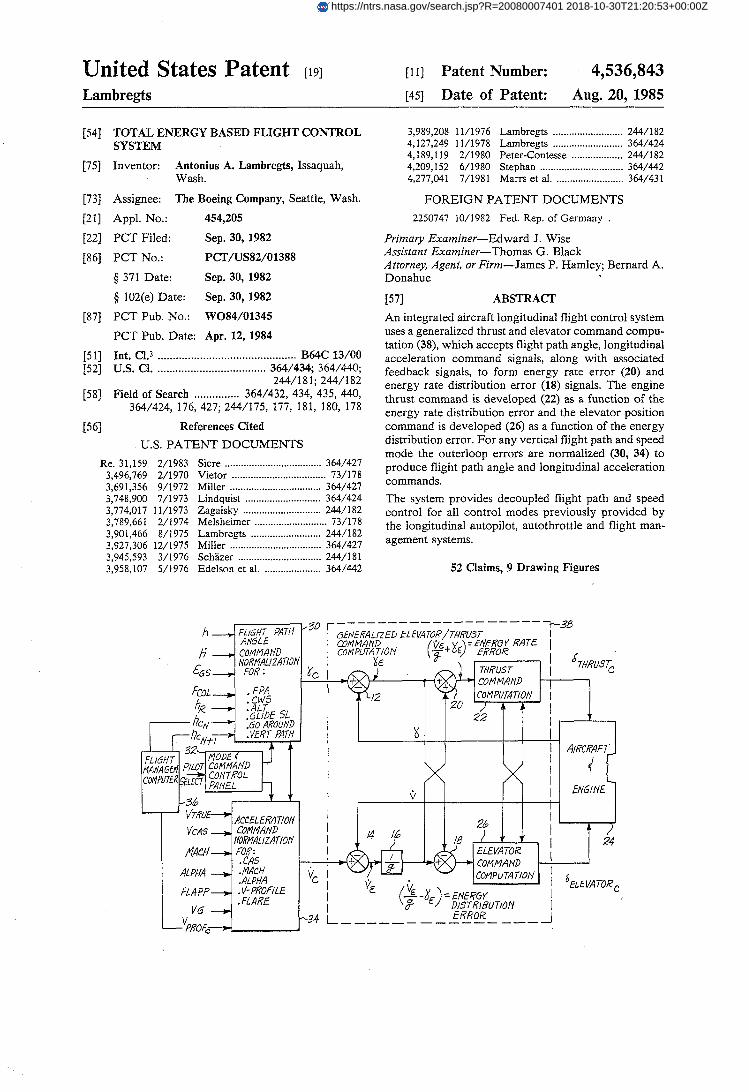
ABSTRACT P71 An integrated aircraft longitudinal flight control system uses a generalized thrust and elevator command compu- tation (38), which accepts flight path angle, longitudinal acceleration command signals, along with associated feedback signals, to form energy rate error (20) and energy rate distribution error (18) signals. The engine thrust command is developed (22) as a function of the energy rate distribution error and the elevator position command is developed (26) as a function of the energy distribution error. For any vertical flight path and speed mode the outerloop errors are normalized (30, 34) to produce flight path angle and longitudinal acceleration commands. The system provides decoupled flight path and speed control for all control modes previously provided by the longitudinal autopilot, autothrottle and flight man- agement systems.
52 Claims, 9 Drawing Figures
https://ntrs.nasa.gov/search.jsp?R=20080007401 2018-10-30T21:20:53+00:00Z

U.S. Patent Aug. 20,1985 Sheet 1 of7 4,536,843
L I
0 I
-I---- 1 ----
h

Sheet 2 of 7 4,536,843
*> >

U.S. Patent Aug. 20,1985 Sheet 3 of 7 4,536,843

U.S. Patent Aug. 20,1985 Sheet 4 of 7 4,536,843
u. s. Patent Aug. 20,1985 I i
I -
Sheet 5 of 7 4,536,843
U.S. Patent Aug. 20,198s Sheet 6 of 7 4,536,843

U.S. Patent Aug. 20,1985 Sheet 7 of 7 4,536,843
5 P $:

4,536,843 1
TOTAL ENERGY BASED FLIGHT CONTROL SYSTEM
BACKGROUND O F THE INVENTION The invention described herein was made in part in
the performance of work under a NASA contract No. NAS1-14880 and is subject to the provisions of Section 305 of the National Aeronautics and Space Act of 1948, Public Law 85-568 (72 Stat. 435; 42 USC 2457).
This invention pertains to the aircraft automatic flight control art and, more particularly, to an integrated longitudinal flight control system based on total aircraft energy.
Numerous autopilot, autothrottle and flight guidance systems for use in aircraft flight control have been de- veloped in the prior art. Such systems have often evolved in a piecemeal fashion and, particularly with respect to longitudinal axis flight control, such auto- matic control systems are characterized by a prolifera- tion of control laws and hardware components. As a result, these systems are overly complex and lacking in functional integration. This has caused numerous opera- tional and performance deficiencies, such as:
low reliability and availability, high procurement and maintenance costs, excessive number of sensors, undesirable flight path and speed control coupling, command capture overshoots and poor tracking, excessive controller activity and turbulence resulting
in poor ride quality, engine wear and waste of fuel, loss of speed control when thrust limits, mode switching transients, inadequate stall/overspeed protection, and unsatisfactory performance in windshear. There is a long felt need in the flight control art,
therefore, for a fully integrated vertical flight path and speed control system which, by developing fundamen- tal solutions to the problem of fully coordinated eleva- tor and throttle control, is capable of a performance level which overcomes these limitations of flight con- trol systems known in the prior art.
SUMMARY OF THE INVENTION It is an object of this invention, therefore, to provide
an improved automatic longitudinal flight control sys- tem in which the aforementioned performance and op- erational deficiencies are avoided.
Another objective of this invention is to provide a universal multi-input/output longitudinal control sys- tem, with appropriately coordinated elevator and throt- tle commands to provide consistent, accurate, decou- pled control over the aircraft’s vertical flight path and speed, in any desired combination of modes and flight condition.
It is a further objective of this invention to provide the above-mentioned automatic longitudinal flight con-
5
10
15
20
25
30
35
40
45
50
55
I I
trol system characteristics, using basic principles of physics and control theory, in particular, the use of thrust to control the total energy state of the aircraft 60 and the use of elevator position to control the energy distribution.
Yet another major objective of this invention is to provide a dramatic simplification in the overall auto- matic control system in terms of required hardware and 65 software, by systematic integration of all control re- quirements, elimination of unnecessary duplication of functions and establishment of priority use of control-
2 lers. As a result, the presently disclosed system not only realizes major improvements in automatic control sys- tem performance and operational capabilities, but also improvements in safety by preventing aircraft stall, overspeed and engine overboost, and cost of ownership by simplifying system development, certification and maintenance.
Briefly, according to the invention, the aircraft verti- cal flight path and speed targets are normalized into vertical flight path angle and longitudinal acceleration command signals yc and V, respectively. These com- mands are combined with their corresponding feedback variables y and V to form the error signals nd ye which, in turn, are used to produce signals representative of the specific total energy rate error E,,
&=Yc+ VJg, (1)
and the energy rate distribution error D
De= -ye+ fie/g.
relative to the aircraft’s vertical flight path and speed targets. In (1) and (2), g is a constant representing accel- eration due to gravity.
The specific total energy rate error $, is controlled to zero-by commanding incremental thrust as a function ?f the E,,signal, while the energy distribution rate error DE is controlled to zero by commandiqg an incremental elevator position as a function of the D, signal, thereby driving the aircraft to the desired vertical flight path and speed targets.
BRIEF DESCRIPTION O F T H E DRAWINGS FIG. 1 illustrates, in block diagram form, the overall
Total Energy Control System architecture with various system inputs, mode and command controls, as well as the generalized thrust and elevator command computa- tion providing decoupled flight path and speed control.
FIG. 2 is a block diagram illustrating signal process- ing details for the system shown in FIG. 1.
FIGS. 3n and 3b are block diagrams illustrating yet further details of the signal processing of the system shown in FIGS. 1 and 2, involving non-linear system operations.
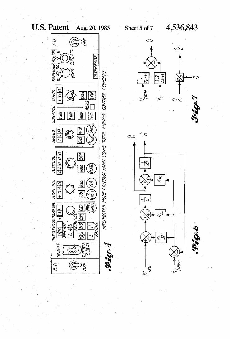
FIG. 4 is an exemplary layout of a mode control panel for selection and indication of various modes and commands.
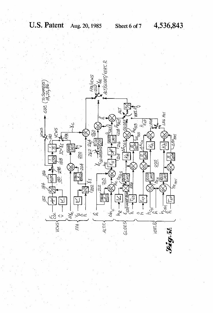
FIGS. 5a and 5b are block diagrams illustrating ac- tual implementation of the various control modes.
FIG. 6 illustrates a third order filter providing iner- tially smoothed altitude and altitude rate signals.
FIG. 7 is a block diagram showing the first order filter, providing a filtered airspeed signal and a filtered airmass referenced flight path angle signal.
DETAILED DESCRIPTION OF THE PREFERRED EMBODIMENT OF THE
INVENTION The overall design philosophy of the present flight
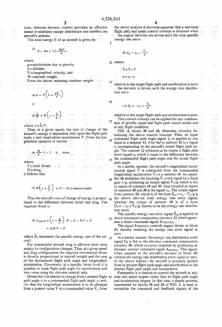
control system is to compute the aircraft’s total energy state and desired state, as represented by flight path, speed and associated targets, and control the total en- ergy error with thrust, while using the elevator to con- trol the energy distribution error between the flight path and speed. For all flight conditions, thrust is the most effective means to change the aircraft’s energy
3 4,536,843
4
means to mo
5
10 where where g=acceleration due to gravity, h=altitude,
W = aircraft weig
. . .
path and acceleration is zero; ntil the energy rate distribu-
tion error (4)kE w(k++)
elative to the target flight path and acceleration is zer -= is control concept can be applied for any combina- LJ
30
tion of specific speed and flight path contol modes and
to a Summer y ‘corresponding to the aircraft’s actual flight pathan- gle. The summer 12 produces at its output a flight pat error signal y E which is equal to the difference between
commanded flight path angle and the actual flight h angle. n a similar the aircraft’s longit tion signal btracted from the
it follows that longitudinal acceleration V, in #a summer 14. An ampli- fier 16 multiplies the resulting V E errof signal by a fixed gain l/g, producing an output signal V,/g which is fed to inputs of summers 18 and 20. Also coupled as inputs to summers 18 and 20 is the signal ye. The outputssignal from summer 20, which is of the form EsE=yE+VE/g is
Thus the aircraft’s rate of change of energy is propor- 45 the above derived total energy rate error signal, whereas th? output of summer 18 is of a form DE= -yE+VE/g, shown to be the energy rate distribu- tion error.
The specific energy rate error signal ESE is applied to 50 thrust command computation circuitry 22 which gener-
ates a thrust command signal G T H R U S T ~ The signal GTHRUST~ controls engine thrust, at block
24, thereby reducing the energy rate error signal to zero.
where Es represents the specific energy rate of the air- 55 In a similar manner, the energy rate distribution error craft. signal D, is fed to the elevator command computation
For commercial aircraft drag is affected short term circuitry 26, which circuitry responds by producing an mainly by configuration changes. Thus, at a given speed elevator control command signal Gelevarorc This signal, and drag configuration the required incremental thrust when coupled to the aircraft’s elevator at block 24, is directly ProPortional to aircraft weight and the sum 60 reduces the energy rate distribution error signal to zero. of the incremental flight path angle and longitudinal In the above manner, the aircraft is precisely guided acceleration. Conversely, at a specific thrust level it is from its present flight path angle and acceleration to the possible to trade flight path angle for acceleration and desired flight path angle and acceleration. vice versa using the elevator control only. Frequently it is desired to control the aircraft to alti-
Given that it is desired to change from a present flight 65 tude and speed targets rather than to flight path angle path angle y to a commanded flight path angle yc and- and acceleration targets. In that case, a simple process, /or that the longitudiflal acceleration is to be changed represented by blocks 34 and 30 of FIG. 1, is used to from a present value V to a commanded value V,, from normalize the command and feedback signals of the
(7) W( y + +) = (T - D) (y assumed small).
tional to the difference between thrust and drag. The required thrust is
(8) Trequtred = ( Y + F) W + D = E/V + D = E3W/V + D
4,536,843 5 6
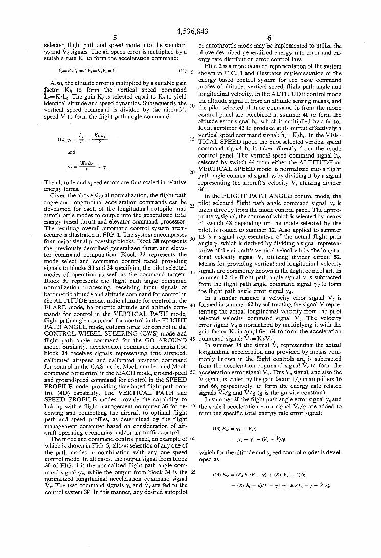
selected. flight path and speed mode into the standard yc and Vc signals. The air speed error is multiplied by a suitable gain K, to form the acceleration command:
or autothrottle mode may be implemented to utilize the above-described generalized energy rate error and en- ergy rate distribution error control law.
FIG. 2 is a more detailed representation of the system (11) 5 shown in FIG. 1 and illustrates implementation of the
energy based control system for the basic command modes of altitude, vertical speed, flight path angle and longitudinal velocity. In the ALTITUDE control mode
lo the pilot selected altitude command h, from the mode control panel are combined in summer 40 to form the altitude error signal he, which is multiplied by a factor Kh in amplifier 42 to produce atj ts output effectively a
hc Khhc vertical speed command signal: h,=Khh,. In the VER- l5 TICAL SPEED mode the pilot selected vertical speed
command signal h, is taken directly from the mo$e control panel. The vertical speed command signal hc, selected by switch 44 from either the ALTITUDE or VERTICAL SPEED mode, is normalized into a flight
2o path angle command signal yc by dividing it by a signal The altitude and speed errors are thus scaled in relative representing the aircraft’s velocity V, utilizing divider energy terms. 46.
Given the above signal normalization, the flight path In the FLIGHT PATH ANGLE control mode, the angle and longitudinal acceleration commands can be 25 pilot selected flight path angle command signal yc is developed for each of the longitudinal autopilot and taken directly from the mode control panel. The appro- autothrottle modes to Couple into the generalized total priate yC signal, the Source of which is selected by means energy based thrust and elevator COnx-xtnd Processor. of switch 48 depending on the mode selected by the The resulting overall automatic control system archi- pilot, is routed to Summer 12, ~l~~ applied to tecture is illustrated in FIG. 1. The system encompasses 12 is a signal representative of the actual flight path four major signal processing blocks. Block 38 represents 30 angle ,,, which is derived by dividing a signal represen-
tor command computation. Block 32 represents the dinal velocity signal v , utilizing divider circuit 52. mode and command pane’ providing Means for providing vertical and longitudinal velocity
modes Of Operation as as the command targets’ summer 12 the flight path angle signal y is subtracted
normalization processing, receiving input signals of the flight path angle error signal 7,. barometric altitude and altitude command for control in
kc=KVVrand ?r=KyVr=K
Also, the altitude error is multiplied by a suitable gain factor Kh to form the vertical speed command h,=Khh,. The gain Kh is selected equal to K, to yield
vertical speed command is divided by the speed V to form the flight path angle command:
identical altitude and speed dynamics. Subsequently the the signal h from an altitude sensing means, and
(12) yc = 7 = - V
and
Kh he Y r = y - Y .
the previously described generalized thrust and eleva- tative of the aircraft’s vertical velocity h by the longitu-
to 30 and 34 specifying the pilot 35 signals are commonly known in the flight control art. In
30 represents the flight path command from the flight path angle command signal yc to form
the ALTITUDE mode, radio altitude for control in the In a manner a error V E is FLARE mode, barometric altitude and altitude corn- 40 formed in Summer 62 by subtracting the repre- mands for control in the VERTICAL PATH mode, senting the actual longitudinal velocity from the pilot
PATH ANGLE mode, column force for control in the error signal VE is normalized by multiplying it with the CONTROL WHEEL STEERING ( c w s ) mode and gain factor K, in amplifier 64 to form the acceleration flight path angle command for the G O AROUND 45 COmmand signal: Vc=KVVe.. mode. Similarly, acceleration command normalization In summer 14 the signal V, representing the actual block 34 receives signals representing true airspeed, longitudinal acceleration and Provided by means corn- calibrated airspeed and calibrated airspeed command monlY known in the flight controls art: is subtracted for control in the CAS mode, Mach number and Mach from the acceleration cofnmand signal V, to form the command for control in the MACH mode, groundspeed 50 acceleration error signal VE. This v, signal, and also the and groundspeed command for control in the SPEED V signal, is scaled by the gain factor l/g in amplifiers 16 PROFILE mode, providing time based flight path con- and 66, .respectively, to form the energy rate related trol (4D) capability. The VERTICAL PATH and signals V,/g and v/g (g is the gravity constant). SPEED PROFILE modes provide the capability to In summer 20 the flight path angle error signal y E and link up with a flight management computer 36 for re- 55 the scaled acceleration error signal V,/g are added to ceiving and controlling the aircraft to optimal flight path and speed profiles, as determined by the flight management computer based on consideration of air- craft operating economics and/or air traffic control.
which is shown in FIG. 5, allows selection of any one of the path modes in combination with any one speed control mode. In all cases, the output signal from block 30 of FIG. 1 is the normalized flight path angle com- mand signal yc, while the output from block 34 is the 65 qormalized longitudinal acceleration $ommand signal
control system 38. In this manner, any desired autopilot
flight path angle command for control in the FLIGHT selected velocity command signal v,. The
form the specific total energy rate error signal:
(13) $6 Y S + prig
The mode and command control panel, an example of 60 = (Yc - Y ) + P c - i3/g
which for the altitude and speed control modes is devel- oped as
(14) hsr = (Kh - + (Kv vr - hlg V,. The two command signals yc and Vc are fed to the = {Kh(hc - h) /V - + { K d V c - ) - V}/g.
4,536,843 7 8
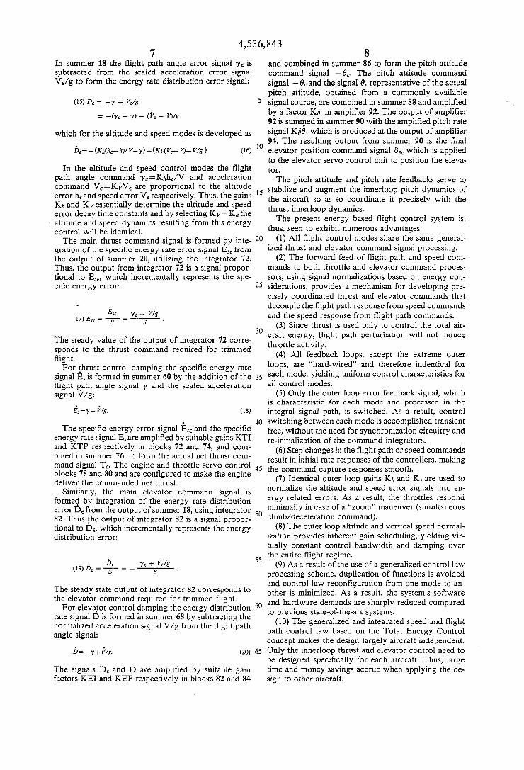
In summer 18 the flight path angle error signal y E is spbtracted from the scaled acceleration error signal vdg to form the energy rate distribution error signal:
and combined in summer 86 to form the pitch attitude command signal -ec. The pitch attitude command signal -Ocand the signal 0, representative of the actual pitch attitude, obtained from a commonly available
5 signal source, are combined in summer 88 and amplified by a factor KO in amplifier 92. The output of amplifier 92 is sumqed in summer 90 with the amplified pitch rate signal G o , which is produced at the output of amplifier 94. The resulting output from summer 90 is the final
(16) lo elevator position command signal 6, which is applied to the elevator servo control unit to position the eleva- tor.
The pitch attitude and pitch rate feedbacks serve to stabilize and augment the innerloop pitch dynamics of
it precisely with the thrust innerloop dynamics.
thus, seen to exhibit numerous advantages.
ized thrust and elevator command signal processing. ( 2 ) The forward feed of flight path and speed com-
mands to both throttle and elevator command proces- sors, using signal normalizations based on energy con-
25 siderations, provides a mechanism for developing pre- cisely coordinated thrust and elevator commands that decouple the flight path response from speed commands and the speed response from flight path commands.
(3) Since thrust is used only to control the total air- 30 craft energy, flight path perturbation will not induce The steady value of the output of integrator 72 corre- throttle activity. sponds to the thrust command required for trimmed (4) All feedback loops, except the extreme outer flight.
For rhrust control damping the specific energy rate loops, are “hard-wired’’ and therefore indentical for signal E, is formed in Summer 60 by the addition of the 35 each mode, yielding uniform control characteristics for flight p.ath angle signal y and the scaled acceleration all control modes. signal V/g: ( 5 ) Only the outer loop error feedback signal, which
is characteristic for each mode and processed in the integral signal path, is switched. As a result, control
40 switching between each mode is accomplished transient free, without the need for synchronization circuitry and re-initialization of the command integrators.
result in initial rate responses of the controllers, making
(7) Identical outer loop gains Kh and K, are used to normalize the altitude and speed error signals into en-
(15)& = -y + kc/g
= -(Yc - Y) + P C - W g
which for the altitude and speed modes is developed as
h,= - CKh(hc-h)/V-Y}+{K&4 Vc- q- V/gJ
In the altitude and speed control modes the flight Path angle command Yc=Khhcn and acceleration command VC=KvV, are PrOPortional to the altitude error h, and speed error v, respectively. Thus, the gains l 5 the aircraft so as to Kh and Kvessentially determine the altitude and speed error decay time constants and by selecting Kv=Kh the altitude and speed dynamics resulting from this energy control will be identical.
gration of the specific energy rate error signal E,, from the output of summer 20, utilizing the integrator 72. Thus, the output from integrator 72 is a signal propor- tional to ES6, which incrementally represents the spe- cific energy error:
The present energy based flight system
The main thrust command signal is formed by inte- 20 (1) All flight control modes share the Same general-
(17) Ex€ = 7 E S € = - ye + v/g s ’
Es = y + V/g. (18)
The specific energy error signal E,, and the specific energy rate signal E,are amplified by suitable gains KTI
in Summer 763 to the net thrust mand signal To The engine and throttle servo control 45 the command capture responses smooth. blocks 78 and 80 and are configured to make the engine deliver the commanded net thrust.
Similarly, the main elevator command signal is
and KTP in 72 and 74, and corn- (6) Step changes in the flight path or speed commands
forme+ by integration of the energy rate distribution ergy errors. As a the respond error D, from the output of Summer 18, using integrator 5o minimally in case of a ‘‘Zoom’’ maneuver (simultaneous 82. Thus the output of integrator 82 is a signal propor- tional to DE, which incrementally represents the energy distribution error:
command). (8) The outer loop altitude and vertical speed normal-
ization provides inherent gain scheduling, yielding vir- tually constant control bandwidth and damping over the entire flight regime.
(9) As a result of the use of a generalized control law processing scheme, duplication of functions is avoided
5 5 D€ Y € + V€/E S ’ (19)D, =- = - S -
and control law reconfiguration from one mode to an-
and hardware demands are sharply reduced compared
The generalized and integrated speed and flight path control law based on the Total Energy Control concept makes the design largely aircraft independent.
(20) 65 Only the innerloop thrust and elevator control need to be designed specifically for each aircraft. Thus, large time and money savings accrue when applying the de- sign to other aircraft.
The steady State output of integrator 82 corresponds to other is minimized. As a result, the system’s software the elevator command required for trimmed flight.
rate.signa1 D is formed in summer 68 by subtracting the normalized acceleration signal V/g from the flight path angle signal:
For elevaror control damping the energy distribution 6o to previous state-of-the-art systems.
D=-y+k/g.
The signals D, and D are amplified by suitable gain factors KEI and KEP respectively in blocks 82 and 84

9 4,536,843
10 tles to go directly to the required steady state position, regardless of the dynamic response lag of the engine, Additional System Provisions and Features
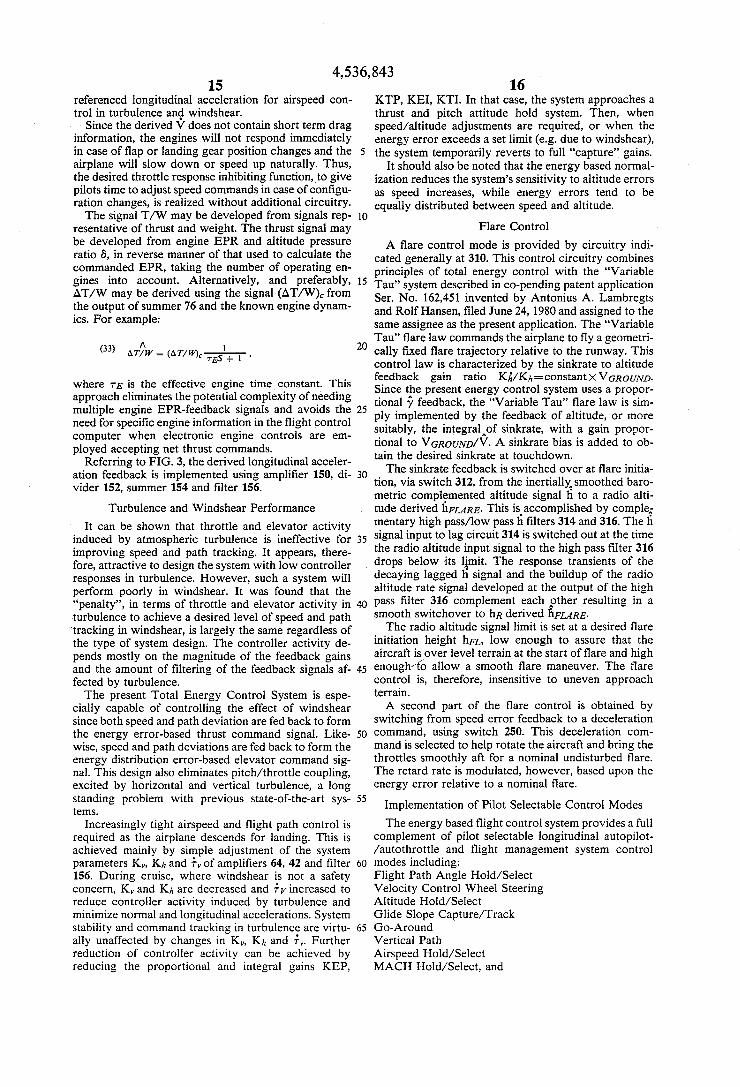
FIG. 3 is a block diagram illustrating further provi- thereby avoiding undesirable throttle position over- sions and features of the Total Energy Control System. shoots. The gain of amplifier 116 is made to vary as an
5 inverse function of the engine gain KE=AEPR/~TH. ROTTLE, which is mainly a function of total air tempera- Gain Scheduling
As previously discussed, normalization of the altitude ture. Thus, the overall engine control loop gain stays error and vertial speed feedback signals provides inher- constant, yielding uniform thrust response dynamics for ent gain scheduling of the path control outerloop, yield- all flight conditions. ing the desired path control dynamics throughout the 10 Future engines may use electronic engine controls, flight envelope. capable of accepting net thrust or EPR commands ex-
The speed control outerloop does not require gain clusively, thereby greatly simplifying the interface with scheduling. the flight control system.
In the elevator innerloop control, gain scheduling of Thurst Limiting the elevator command is required to compensate for the 15
increasing elevator effectiveness with increasing speed Most state-of-the-art engines do not feature built-in and maintain uniform dynamics of the augmented pitch protection against inadvertently exceeding the engine’s attitude responses. Thus, a multiplier 100 scales the operating limits. The Total Energy Control System has, elevator command output 6, by a gain factor KCAS, therefore, been designed to safeguard the engines using variable gain amplifier 102. KCAS is a function of 20 against overboost. The EPR-limit signal is supplied by the calibrated airspeed CAS. an EPR-limit computing means. As described above,
The thrust command is scheduled proportional to the engine is controlled to an incremental thrust com- aircraft weight to provide the exact net thrust command mand AEPR,. In order to limit the engine thrust to an AT, that is required to maintain uniform flight path and absolute EPR-limit, an absolute command signal EPR, speed control dynamics with varying aircraft weight. 25 is formed, as seen in FIG. 3 by the addition of the As seen from equation (8), the required incremental EPRIDLE signal to the AEPR, signal in summer 302. If thrust is proportional to the sum of the incremental the resulting EPR, signal exceeds the EPR-limit signal, flight path angle and normalized acceleration and also as determined from the output of summer 304, the dif- proportional to aircraft weight. Thus, multiplier 77 ference signal is fed back with high gain into the thrust multiplies the specific thrust command signal output 30 command integrator 72 so that, in effect, the EPR, from summer 76 by a signal W which is representative signal remains limited to the EPR-limit. This way, also, of aircraft weight. overshoots of the throttle position corresponding to the
Since the required incremental net thrust command is EPR-limit are avoided. computed precisely, the engine must be controlled to Similar provisions may be used to limit the AEPR, put out the commanded net thrust. However, the en- 35 signal to a desired minimum value and the throttle posi- gines are generally controlled by variables other than net thrust, for example throttle position, engine pressure ratio EPR or fan speed N1. The net thrust command is, therefore, converted into the appropriate engine varia- In most previous state-of-the-art automatic flight ble-AEPR,for the example case. To this effect, the net 40 control systems it has been possible to stall the aircraft thrust command is first normalized to compensate for through inadvertent operation. For example, in conven- the altitude effect on the engine performance by divid- tional speed control autothrottle systems, it is possible ing the thrust command, in divider 100, by the altitude to safeguard against stall, but only to the extent that the pressure ratio factor 8=p/po, where p is the actual required thrust does not exceed the thrust limit. Thus, atmospheric pressure at altitude and po is the sea level 45 during climb out with limit-thrust, such autothrottles pressure. Finally, the normalized net thrust command is cannot protect against stall. Likewise, during descent converted into an engine pressure ratio command, using with the thrust at idle, conventional autothrottle sys- amplifier 110, with a gain factor KEPR which is gener- tems cannot prevent the actual speed from exceeding ally a function of Mach number. the selected speed command or the maximum allowable
EPR, (or N1,) command, the actual servo control may Therefore, in the present Total Energy Control Sys- use throttle position. In that case, it is necessary to use tem, stall and overspeed protection control has been throttle position as an intermediate control variable. developed that is foolproof regardless of the selection of Thus, a control loop, generally indicated at 112, in- automatic control modes. This has been achieved by cludes a summer circuit 114, and amplifier 116, a posi- 55 integration and prioritizing speed control between the tion servo 118, the engine 120, a summer circuit 122 and selected speed command and the minimum or maximum the amplifier 124. The gain of amplifier 124 is the in- safe speed, using the generalized thrust and elevator verse of the engine gain KE=AEPR/ATHROTTLE command computation as seen in FIG. 3. and provides the steady state throttle position command A summer circuit 292 produces an output signal at the input of summer 114 required for a given AEPR,. 60 which is the difference between the aircraft’s actual Thus, in the short term the throttles are controlled to a angle of attack a (alpha) and the maximum allowable “predicted” position corresponding to the commanded angle of attack reference signal (*.REF. The signal (*.REF AEPR,and tine control of the engine thrust is achieved is computed as a function of flap position and MACH through the EPR loop. Summer circuit 122 combines number in block 290. The resulting angle of attack error the EPR feedback signal from the engine with a signal 65 signal is normalized into a speed equivalent error VEa, EPRIDLE representative of the engine pressure ratio at using a gain factor K, which is equal to the steady state idle and the AEPR, to form an engine pressure ratio value of the derivative dV/da. The short period a- error feedback signal. This approach allows the throt- response is attenuated by processing the normalized
tion command to the desired forward and aft limits.
Speed Limiting
Although the engine is ultimately controlled to a 50 speed.

50
55
60
65
4,536,843 11 12
angle of attack error signal though a lag circuit 293, This control configuration-remains in effect until the and the effect of the lag on the control dynamics is ye reduces to a point where the throttles are driven out compensated by the addition of a short term airspeed of the limit position. At that point, closed loop flight error signal from the output of washout circuit 296 in path and speed control is resumed. summer 297. The input to washout circuit 296 is formed 5 Similarly, when the thrust limit is reached due to a in summer 295 by combining a signal representative of speed command change, the VE signal input to the ele- true airspeed and a signal representative of the desired vator integral control signal path must be removed to minimum speed increment AV which is developed as a prevent it from biasing the flight path control. This may function of the aircraft flap position in circuit 294. The be done by way of amplifier 146, which has a variable result is a feedback signal VMIN~ that is equivalent to 10 gain factor KVDE. Alternatively, a “washout” circuit airspeed error relative to the steady state speed that may be used. corresponds to QREF. The signal VMINE is continually
to the airspeed error from the CAS* MACH Another embodiment, requiring less logic, uses a Cc
limit in combination with the y E variable gain amplifier Or SPEED switch 298 whenever it is more positive than the regular 15
airspeed and angle of attack control is transient free and completely transparent. There iS no difference in speed
not switch in generally unless a speed command is se- 20 lected which would result in exceeding QREF. In that
mode and v‘INc is via 144. The specific total energy rate is represented by . .
speed control error signal. Thus, switchover between Ex= V+gy. (21)
Therefore, when thrust limits the maximum accelera-
Thus, by limiting the signal qcin limit circuit 140 to o+gy and removing the yesignal to the elevator control signal path while the throttles are
response dynamics, and the Of attack does tion/deceleration that can be achieved by bringing y to is
the ’peed commanded by the regu1ar Inode is ignored and the aREF becomes the command, thereby maintaining the ’peed at a desired in the limit position, the maximum level (,,=O) accelera-
tion/deceleration is obtained. This latter method pro- margin above the stall speed. Alternatively, the mini- 25 mum safe speed ViwIN may be developed from signals representative of the aircraft weight and flap position to form the VMIN~ signal.
Analogous to the minimum speed control, the speed control is bounded on the upper side by the maximum 3o operating speed vIwomM0 control, which is switched in whenever the airspeed viwAx, relative to VI~o/MIwo and developed in circuit 300 is more nega- tive that the airspeed error of the regular speed control mode. 35 VCLIMIF V-UE
Since the speed limiting control feeds into the gener- alized flight path and speed control circuitry, which includes the speed control priority provision using ele- vator only in case of thrust limiting, all flight modes are
flight conditions. Automatic switching to VMIN or VIw~x control is
indicated by flashing the inappropriate speed command or an alert light on the mode control panel or other primary information display.
Control Priority When Thrust Limited Simultaneous closed loop control of the flight path
and the speed requires both thrust and elevator control. Therefore, when the thrust limits, control of only one variable can be continued through the elevator. Equa- tion (8) indicates that for a given constant speed (V=O) and drag configuration (D) the achievable flight path angle y is entirely determined by the thrust. Therefore, the following control priority has been developed:
When the thrust limit is reached as a result of a flight path command, that flight path command cannot be satisfied while maintaining speed. In that case, it is desir- able to continue active speed control through the eleva- tor and give up active flight path control. This is ac- complished by removing the yesignal input to the eleva- tor integral control signal path at summer 18 to prevent it from biasing the speed control.
To smooth the control reconfiguration, the y E is not discretely switched out but, rather, “washed out” as a function of time, using amplifier 144 with a variable gain factor KGAE. Alternatively, a conventional “wash out” circuit may be used.
vides the much desired capability to accelerate during climb with the throttles at the forward limit, and to decelerate during descent with the throttles at idle with- Out having to change
The V, limit is further used to partition the total en- ergy rate authority during conditions with limit thrust between flight path and speed control. This is achieved by
laws.
Or
(22) +cLIMIr=~(p+’+gy).
protected against and Overspeed for 40 whichever is greater than the thrust reaches the for- ward limit, and
QCLIMIF +-sY~
45 or
QcL,MIr=~( ~ + K Y X (23)
whichever is less when the thrust reaches the aft limit. In one embodiment the constant K was set to 0.5 when thrust reached the forward limit and to 1.0 when thrust reached the aft limit, resulting in a -50% reduction of the maximum thrust climb gradient to satisfy a large acceleration command and a temporary leveling off during idle descent in order to satisfy a deceleration command.
While in the glide slope or vertical path mode, it is sometimes advantageous to prioritize flight path control to assure continued flight path tracking during condi- tions with limit thrust. For example, when a decelera- tion is commanded during glide slope capture, it is de- sirable not to interrupt the glide slope capture control. In such cases, flight path control is prioritized by tem- porary removal of the V, signal to the elevator control signal path. This can safely be done as long as speed stays within the safety envelope of QREF and VMO/MMO. Therefore, speed control priority is made

13 4,536,843
~.
absolute whenever the selected speed control mode is overridden by VMIN or VMAX control.
The control dynamics of either speed or flight path control using elevator only does pot change when thrust limits and either the y E or the VJg signal input to the elevator command computation is removed. This is so because, at constant thrust and drag, the incremental change in flight path y is equal and opposite to the incremental change in o /g , as seen in equation (7), and the gains of the flight path angle and normalized accel- eration feedbacks in the development of the elevator command are identical. Furthermore, the gains of the flight path angle and normalized acceleration feedbacks leading up to the pitch attitude command are identical to the corresponding gains leading up to the specific thrust command, since at constant speed d ( T y ) / d y = d O / d y = 1, while at constant thrust also $y/d(V/g)= 1. Therefore, when thrust limits, a desired V/g i; obtained by an instantaneous attitude change AO=V/g, in effect replacing the thrust force by an equivalent gravity force.
When thrust limits and active flight path control is abandoned, an indication is given to the pilot by flashing the flight path command readout or by an alert light on the mode control panel.
Elevator Innerloop Control The elevator innerloop control, shown in the embodi-
ment of FIG. 3, uses pitch rate and pitch attitude feed- backs. Alternatively, it is possible to use a normal ac- celeratiodpitch rate feedback innerloop elevator con- trol without deviating from the spirit of the present invention.
Normal and Longitudinal Acceleration Limiting In conventional pitch autopilots it has been difficult
to limit normal acceleration during vertical maneuvers on the one hand, while providing responsive, over- shoot-free capture of the target flight path on the other hand. This problem has been solved in a simple, effec- tive manner in the present Total Energy Control Sys- tem design.
The pathhpeed control feedbacks and gains have been selected to yield critically damped responses to changes in the commanded flight path and/or speed for all conditions. Therefore, the normal acceleration, which is equal to Vy, can simply be limited by rate limiting the commanded flight path angle to a value
jc=aNLIMIT/ (24)
where aNLIMITis the maximum allowed normal acceler- ation. This rate limit is applied directly to the flight path angle command signal y,, using rate limit circuitry 130 in FIG. 3.
In the altitude control modes yc=KhhE/V=hc/V and thus, the vertical acceleration limit may be achieved by rate limiting the vertical speed command h, to a value
hc=aNLIMIF (25)
This approach is used for the altitude mode implementa- tion shown in FIG. 5.
To maintain a mat+ between the speed control and the path control, the Vc signal is also rate limited to a value
5
10
15
20
25
30
35
40
45
50
55
60
65
using rate limiter 134. This assures that, in case of simul- taneous flight path and speed commands, the input sig- nals to the thrust or to the elevator command computa- tion cancel, thereby minimizing the unnecessary con- troller activity. The rate limit on the acceleration com- mand signal V, also helps to smooth the throttle and elevator response for large commands and reduce nui- sance activity. due to turbulence.
Use of tpe Vcrate limit necessitates the use of a corre- sponding V, amplitude limit. In the linear region, the acceleration response called for is
. . v= vcl=ot-l/T (27)
and the rate of change of acceleration is then .. . v=-(V CT=O/T)t--'? (28)
where r=I/K, and Vct,0=Kv VE1=0. Thus, in re- sponse to a speed command change, the system calls for a rate of change of acceleration which is maximum at t - 0
vMAX= - Vci=O/T. (29)
This rate of change of acceleration called for by the control law should be equal to or less than the set rate limit of V,. Therefore,
~ c i = O / T s (aNLIMIZ)/
or
vc1=,s (raNLIMIZ)/ K (30)
which is achieved by limiting the aTplitude of c, to (raNLIMI&/V, or the amplitude of V E to
( T 2 a N L I M I ~ ) / V = ( a N L I M I Z ) / ( v K Y ~ ) . (31)
This \i, ampjitude limit is provided by circuit 140. Fail- ure to limit V, would result in response overshoots after large changes i n the commanded speed, since the initial amelitude of V, would result in a higher rate of change of V, than the actual rate .limit can accomodate.
Likewise, a matching h, amplitude limiting circuit 142 has been implemented to assure that altitude re- sponse overshoots are avoided when responding to large altitude commands with a rate limited or -ye
Derivation of the Longitudinal Acceleration Signal To obtain optimum dynamic system performance, the
acceleration feedback signal is derived from engine thrust T, aircraft weight W, flight path angle y, and true airspeed VTRUE
where S is the Laplace operator. The term (-7 + T/W) represents the normalized acceleration along the flight path, neglecting the effect of drag variation. This term is washed out and complemFnted by a lagged airspeed rate term t? reference the V to airspeed for the long term. The V signal feedback is superior to an inertially
4.536.843 15
referenced longitudinal acceleration for airspeed con- trol in turbulence and windshear.
Since the derived V does not contain short term drag information, the engines will not respond immediately in case of flap or landing gear position changes and the airplane will slow down or speed up naturally. Thus, the desired throttle response inhibiting function, to give pilots time to adjust speed commands in case of configu- ration changes, is realized without additional circuitry.
The signal T / W may be developed from signals rep- resentative of thrust and weight. The thrust signal may be developed from engine EPR and altitude pressure ratio 6, in reverse manner of that used to calculate the commanded EPR, taking the number of operating en- gines into account. Alternatively, and preferably, AT/W may be derived using the signal (AT/W), from the output of summer 76 and the known engine dynam- ics. For example:
(33f AT/W A = (AT/WC- , 1
where TE is the effective engine time constant. This approach eliminates the potential complexity of needing multiple engine EPR-feedback signals and avoids the need for specific engine information in the flight control computer when electronic engine controls are em- ployed accepting net thrust commands.
Referring to FIG. 3, the derived longitudinal acceler- ation feedback is implemented using amplifier 150, di- vider 152, summer 154 and filter 156.
Turbulence and Windshear Performance It can be shown that throttle and elevator activity
induced by atmospheric turbulence is ineffective for improving speed and path tracking. It appears, there- fore, attractive to design the system with low controller responses in turbulence. However, such a system will perform poorly in windshear. It was found that the “penalty”, in terms of throttle and elevator activity in turbulence to achieve a desired level of speed and path tracking in windshear, is largely the same regardless of the type of system design. The controller activity de- pends mostly on the magnitude of the feedback gains and the amount of filtering of the feedback signals af- fected by turbulence.
The present Total Energy Control System is espe- cially capable of controlling the effect of windshear since both speed and path deviation are fed back to form the energy error-based thrust command signal. Like- wise, speed and path deviations are fed back to form the energy distribution error-based elevator command sig- nal. This design also eliminates pitchhhrottle coupling, excited by horizontal and vertical turbulence, a long standing problem with previous state-of-the-art sys- tems.
Increasingly tight airspeed and flight path control is required as the airplane descends for landing. This is achieved mainly by simple adjustment of the system parameters K,, Kit and i, of amplifiers 64, 42 and filter 156. During cruise, where windshear is not a safety concern, K, and Kh are decreased and iv increased to reduce controller activity induced by turbulence and minimize normal and longitudinal accelerations. System
16 KTP, KEI, KTI. In that case, the system approaches a thrust and pitch attitude hold system. Then, when speed/altitude adjustments are required, or when the energy error exceeds a set limit (e.g. due to windshear),
5 the system temporarily reverts to full “capture” gains. It should also be noted that the energy based normal-
ization reduces the system’s sensitivity to altitude errors as speed increases, while energy errors tend to be equally distributed between speed and altitude.
Flare Control A flare control mode is provided by circuitry indi-
cated generally at 310. This control circuitry combines principles of total energy control with the “Variable
l5 Tau” system described in co-pending patent application Ser. No. 162,451 invented by Antonius A. Lambregts and Rolf Hansen, filed June 24, 1980 and assigned to the same assignee as the present application. The “Variable Tau” flare law commands the airplane to fly a geometri-
2o cally fixed flare trajectory relative to the runway. This control law is characterized by the sinkrate to altitude feedback gain ratio Ki/Kh =constant X VGROUND. Since the present energy control system uses a propor- tional feedback, the “Variable Tau” flare law is sim-
25 ply implemented by the feedback of altitude, or more suitably, the integral-of sinkrate, with a gain propor- tional to VGROUND/V. A sinkrate bias is added to ob- tain the desired sinkrate at touchdown. , The sinkrate feedback is switched over at flare initia-
tion, via switch 312, from the inertiallxsmoothed baro- metric complemented altitude signal li to a radio alti- tude derived hFuRE. This is. accomplished by comple; mentary high passflow pass h filters 314 and 316. The h
35 signal input to lag circuit 314 is switched out at the time the radio altitude input signal to the high pass filter 316 drops below its limit. The response transients of the decaying lagged fi signal and the buildup of the radio altitude rate signal developed at the output of the high
40 pass filter 316 complement each $her resulting in a smooth switchover to hR derived hFLARE.
The radio altitude signal limit is set at a desired flare initiation height hFL, low enough to assure that the aircraft is over level terrain at the start of flare and high
45 enough40 allow a smooth flare maneuver. The flare control is, therefore, insensitive to uneven approach terrain.
A second part of the flare control is obtained by switching from speed error feedback to a deceleration
50 command, using switch 250. This deceleration com- mand is selected to help rotate the aircraft and bring the throttles smoothly aft for a nominal undisturbed flare. The retard rate is modulated, however, based upon the energy error relative to a nominal flare.
Implementation of Pilot Selectable Control Modes The energy based flight control system provides a full
complement of pilot selectable longitudinal autopilot- /autothrottle and flight management system control
Flight Path Angle Hold/Select Velocity Control Wheel Steering Altitude Hold/Select Glide Slope Capture/Track
10
3o
5 5
60 modes including:
stability and command tracking in turbulence are virtu- 65 Go-Around ally unaffected by changes in K,, Kh and +”. Further reduction of controller activity can be achieved by reducing the proportional and integral gains KEP, MACH Hold/Select, and
Vertical Path Airspeed Hold/Select

17 4,5 36,843
18 Speed Profile.
The Total Energy Control System allows a simpler, more effective mode control panel, illustrated in FIG. 4, for the selection of these modes. The control functions are grouped into longitudinal flight path, speed ’and lateral flight path control modes. The system can be engaged by pressing any longitudinal flight path or speed mode engage button. The default speed or flight path mode (calibrated airspeed or flight path angle) will also engage. Only one path and one speed mode can be engaged simultaneously. The glide slope and vertical path modes have both an ARM and ENGAGE status. When these mode buttons are pressed and certain pre- engage requirements are met, these modes will arm, indicated by an amber arm light. Automatic engage follows and the light turns green when certain engage conditions are met.
All modes are controlled by single control knobs and arm/engage switches which are operational over the entire flight regime. No pilot action is ever required to resolve mode control conflicts or prevent unsafe condi- tions.
FIG. 5 is a detailed block diagram showing the pre- ferred implementation of the various pilot selectable control modes.
The flight path angle mode (FPA) is the basic path mode. The FPA mode circuitry is indicated generally at 200. This has been implemented rather than the vertical speed, because it allows precise range/altitude intercept capability when used in combination with the horizon- talhertical situation displays for profile descent opera- tions. A special case of the range/altitude intercept is the final approach to the runway. With the proper navi- gation/display computations, it becomes a simple mat- ter to target the flight path angle to the approach end of the runway. For this reason, inertial (rather than air- mass referenced) flight path angle y~ is used for the FPA mode. It is obtainsd by dividing the inertially smoothed vertical speed h, derived in the complemen- tary filter shown in FIG. 6, by the ground speed, in divider circuitry 202. The flight path angle command y c is formed by adding the flight path angle that existed at the time of mode engagement, and memorized in the track and hold circuitry 204, to the desired incremental flight path command Aye The Ayc signal is developed by counting the pulses of an optical encoder (not shown) which is stimulated by rotation of the FPA select knob (FIG. 4) on the mode control panel.
A Velocity Vector Control Wheel Steering (VCWS) mode has been implemented using the Total Energy Control concept to provide very precise manual maneu- vering capability and superior aircraft handling and response characteristics. Direct control over the air- craft’s velocity vector facilitates execution of flight paths which are inertially, i.e. earth referenced, such as glide slope capture and tracking. Such a control capa- bility also reduces pilot workload sharply, since the aircraft will track the inertial flight path established by the pilot, in spite of the disturbances.
Such a control mode was earlier developed as a sepa- rate capability and is described in previously identified patent application Ser. No. 162,451.
The present Total Energy Control system provides an even more ideal baseline control law for implementa- tion of the VCWS mode, since it inherently provides decoupled control over the amplitude (V) of the air- craft’s velocity vector and its direction (7).
Only the yc processing and the response augmenta- tion design need to be added to the baseline control concept of FIG. 3. This is shown in FIG. 5, with the circuitry indicated at 180.
In the VCWS mode the yc signal is developed by scaling the column force signal FCOL, after processing the signal in dead zone circuit 182, by a factor inversely proportional to inertially smoothed speed V in divider 184 and a factor K G D C in amplifier 186 to form the
10 commanded :ate of change of flight path angle signal +e The gain yc/Fcor. is scaled inversely proportional to V to provide approximately constant stick force per unit normal acceleration, regardless of the speed. The T, signal output from amplifier 186 is filtered by a small
15 lag in circuit 188, and integrated in circuit 190 to form the yc signal. The small lag provides a more natural response for yc which is used for pilot display to close the short term pilot control loop.
The dead zone circuit 182 guards against inadvertent 20 drift of the yc signal when the pilot does not intend a
maneuver. The natural response of the baseline control system to
a ycsignal is too sluggish for manual control. Therefore, response augmentation is provided by feeding the qC
25 signal to the input of the thrust command integrator 12 of FIG. 3 via summer 20 using the gain amplifier 292. The signal Tc is also fed to summers 18 and 86 of FIG. 3 via gain amplifiers 294 and 296 for the development of coordinated pitch attitude command. The gains of am-
30 plifiers 292, 294 and 296 have been selected to provide the desired y response quickening without affecting the decoupling from speed control. To accommodate the condition where the steady state flight path angle limit is reached due to thrust limiting, the f c input to circuit
35 188 is removed using switch 298 at the same time the yc signal is removed from summer 18. At that point a col- umn force will not increase yc further and the column will stiffen due to the automatic control system action to prevent exceeding of the limit flight path angle. As a
40 result, very smooth and responsive manual control over y has been provided with the additional safety feature of indication of the steady state performance limit through the stiffening of the column force. The risk of stalling or overspeeding the aircraft during manual
The altitude mode can be directly engaged by push- ing the HOLD button. It can also be armed to engage and capture a pre-selected altitude, simply by dialing the altitude knob to the desired altitude when another
50 path mode is engaged and pressing the CAPT button. The mode then automatically engages to capture when the selected altitude is intercepted. While engaged, the altitude command can be changed to any desired value and the altitude mode will execute the change unless the
55 HOLD button has been pushed first. No mode switch- ing is required. For substantial altitude changes, maxi- mum thrust will be used. Speed control remains in effect at all times, and vertical maneuvers will not cause signif- icant speed deviation since elevator and throttle com-
As discussed above, the y E signal is developed by
5
45 VCWS control is thereby largely eliminated.
60 mands are precisely coordinated to prevent this.
normalization of the altitude error: 9 -
Yt=Yc-Y=(Khha--h)/V. (34)
The normalization of the altitude error uses acomple- mentary filtered airspeed/groundspeed signal V which is representative of airspeed for low frequencies. The
65

19 4,536,843
20 filter is shown in FIG. 7. Low frequency airspeed is separate filtering is used and, thus, the associated filter used to preserve the energy relationship between alti- switching and initialization problems and complexities tude and airspeed and the filtering is needed to avoid are avoided. undesired controller activity due.to turbulence. Go-around mode control circuitry is indicated gener-
If he is very large, the sign of h e ~ ~ ~ W i 1 1 be the Same 5 ally at 260. The go-around mode is achieved by simply as the sign of he indicating that the commanded flight switching, via switch 262 and switch 202, to a fixed Path angle for intercepting the target altitude is steeper flight path angle command ( y c ) ~ ~ . This ( y c ) ~ ~ signal is than the actual flight path angle as established by the selected to require full power for a nominal airplane mode in control. Mode switch-over to A L T is-inhibited weight and thrust condition. upon gomaround engage- as long as this condition exists. As he reduces, heAL:rwill 10 ment, the aircraft will simply be rotated to establish eventually change sign, indicating that from that point ?=(yJGA causing the throttles to drive to the forward on the ALT control law commands the aircraft to align itself with the target (horizontal) path.
Thus, the A L T mode is engaged as seon as the sign of 6dLTbecomes opposite to the sign of hcAL:r. Since only 15 the signal of the integrator signal path is switched, mode switching is always transient free and fully adaptive to any flight condition. The integrators never need re-ini-
tured without overshoot. The capture time constant is 2o shaping of the initial versus final response. Selection of a fixed ( ~ , ) G A prevents excessive climb rates and pitch set by the gain Kh in amplifier 214.
n i S simple mode transitioning concept eliminates the attitudes in case of a high thrust-to-weight ratio condi- capture sub-mode and the command synchronization tion. In that case the system uses less than full power. hardware or software that is used in conventional con- The system is also safe for very low thrust-to-weight trol laws to achieve smooth mode transitioning. conditions (e.g. for failed engine) because the throttle
The (fi,)A,rTsignal is limited, by amplitude limiter 216 25 simply drives to the forward limit and speed control is and rate limiter 218, to assure that, for large changes in maintained through the elevator, even if the (YC)GA the commanded altitude, the vertical speed and vertical cannot be satisfied entirely. The previously described acceleration stay within desirable limits and also to speed control priority logic assures this operation. prevent altitude capture overshoots. However, for most 3o The commanded airspeed hold/select mode (CAS), flight conditions, the achievable h is restricted by the which is the basic speed mode, is implemented using the available thrust/drag. circuitry shown generally at 230. As discussed above, a
The glide slope control mode is implemented using speed mode is always engaged simultaneously with the the circuitry indicated generally at 220. This system is path mode. The CAS command is formed, as with the analogous to the altitude control mode. The only differ- 35 path mode commands, by memorization of the existing ences are: speed at mode engage, in track and hold circuit 232,
(1) a h e a r path deviation is developed from the glide with the addition of an incremental command signal slope using radio altitude hR, and CAS, resulting from rotation of a speed knob. The CAS
(2) a sinkrate signal AhGS relative tQ the glide slope is error, which is the difference between CASc and the used instead of the absolute sinkrate fi. This is done by 4o actual CAS is converted into a true airspeed error, via complementary filtering of the vertical speed and the divider 234, using an altitude dependent conversion linearized glide slope deviation signal to provide the factor. This is done to keep the gain relationship be- proper relationship between (A&)Gs and A ~ ~ C S meded tween true airspeed and the acceleration damping con- for proper mode engagement. stant over the entire flight path envelope and thereby
has a “pre-engage” Or “arm” status 45 maintain constant speed control dynamics. The result- where (~ .€ )Gs is computed but control engagement is ing airspeed error VaSEL is normalized into an accelera- inhibited until the sign Of(&)GSbeCOmeS opposite to the tion command v, by multiplication with the factor K,,
limit at approximately maximum rate. Speed control is maintained at all times. Thus, the pilot can then manage speed and flap commands as desired. Flaps may be retracted before changing the commanded speed since the a-limit control maintains a stall margin, regardless Of the ’peed and flap position.
tialization. The commanded flight path is always cap- The (yC)GA signal has a shaping 264 to
This mode
sign Of (Ah’,)Gs, indicating the point where the glide capture trajectory is tangentia1 to the existing
flight path‘ Thus, glide
via amplifier 236. The acceleratio? command vc, to- gether with acceleration feedback +, are used to form
5o the acceleration error signal +, for use in developing captures are adapted for the specific approach speeds and initial
The MACH command signal is developed by cir- flight path, and capture overshoots are avoided.
the CAS command. The MACH command is converted slope control has an important advantage over a con- ventional h feedback system. While tracking the glide
by the elevator and thrust command integrators and is the speed Of sound’ The speed Of sound (a) is
the glide slope causes, therefore, no control transient, divider circuit 252. The true airspeed error is formed by
6 feedback signal are, thus, eliminated at no additional 60 command V T ~ The resulting airspeed error is routed via hardware or software expense. switch 270 and switch 280 to amplifier 236 to produce
the vc
path angle error signal Since the speed control is always executed in terms of true airspeed, the MACH or CAS modes can be used
An automatic CAS to MACH switchover is built into the system which occurs when reaching a predeter- mined MACH number during climb and a MACH to
both the thrust and elevator commands.
The proportiona1 flight path feedback for glide cuitry indicated generally at 250 in a manner similar to
slope, the steady State y feedback signal is balanced 55 to a true airspeed command v T C by multiplication with
unaffected by the approach speed. A deceleration on by dividing true airspeed by MACH in a
and glide slope departures as occur in systems using an subtracting true vTRUE from the true
The use of integral control of the normalized flight
(&)Gs= K h b . h ~ ~ - ( A ~ G S . + TS~;)/(TS+ I ) (35) 65 interchangeably.
provides inherent inertial smoothing of the beam devia- tion signal hhGs, with a roll-off frequency VT. No
4,5 36,843 21
CAS switchover on descent when CAS reaches a pre- determined value. The switchover points can be set as desired .to suit a particular climb and descent procedure.
A AV, signal is developed from the VESEL and the v ~ ~ ~ ~ s i g n a l s using ?washout circuit 282 and rate limit circuit 284. This AV, signal is used to command the acceleration that is required during constant MACH- /CAS climb or descent. Without it, some airspeed error would develop to null the ir, signal.
The rate limit circuit 284 is used in the A+, signal development to filter out undesired signals due to step changes in the CAS, or MACHc.
The present energy based flight control system pro- vides coordinated control of speed and flight path. It is, therefore, ideally suited for controlling vertical paths and speeds that are pre-programmed in a flight manage- ment computer. The advantages of using the present system for vertical path and speed profile control are:
the control switching to successive legs of the verti- cal path is handled in a simple and effective manner;
it eliminates the need to develop separate flight man- agement control laws;
the required interfaces with the flight management computer are simple;
complex mode logic for control law switchover and initialization is avoided; and
performance for vertical path and speed profile modes is identical to other autopilot modes.
The vertical path control mode circuitry is indicated generally at 290. Concurrent inputs hcN and hcN+l of the commanded altitude for the present and for the next straight line segment of the vertical path profile are used.
The vertical path profile may be developed in a flight management computer based on considerations for air traffic control or optimal aircraft operating economy. The vertical path control command development is entirely analogous to the glide slope control command development, except the dual computations for the present and the next leg are used. Computations for the next leg are carried out simultaneously with the compu- tations for the present leg to determine the exact time for starting the capture of the next leg, just as is done for glide slope control.
As soon as control reverts to the second computation branch, the first computation branch is supplied with the altitude command information for the next leg. For this purpose the legs must be extended backwards to find the h, for the present position of the aircraft. Con- trol thus reverts from one computation leg to the other and back, as the successive legs of the profile are flown.
In the speed profile mode, which may be used to provide time referenced control (4D), a commanded groundspeed VG,, along with the actual aircraft groundspeed VG, is routed via switch 280 as inputs to the standard control circuitry. The present energy based flight control system can execute a speed com- mand versus time profile without causing deviations from the vertical path profile.
Thus, for any combination qf flight path and speed modes, the generalized y E and V, signals are developed as shown in FIG. 5, for coupling to the standard thrust and elevator command Drocessing shown in FIG. 3. For
22 In summary, an energy based flight control system
has been described in detail. Whereas a preferred embodiment of the invention has
been discussed, it should be apparent that many modifi- 5 cations and variations thereto are possible, all of which
fall within the true spirit and scope of the invention. I claim: 1. An aircraft longitudinal flight control system for
automatically controlling the aircraft’s flight path and 10 speed, using engine thrust and elevator control surface
position, comprising: means for developing an incremental net thrust com-
mand signal ATc which is a linear combination of a signal representative of the aircraft’s total energy error with respect to the flight path and speed command targets and a signal representative of the rate of change of the aircraft’s total energy;
thrust control means for automatically controlling the incremental net thrust of the engines to said incremental net thrust command signal AT,, such that said total energy error is reduced to zero;
means for developing an incremental elevator posi- tion command A6ec for controlling the deviation of the aircraft from a commanded flight path; and
25 elevator position control means for automatically positioning the elevator to said incremental eleva- tor command signal A6ec such that said deviation of the aircraft from the commanded flight path is reduced to zero.
2. An aircraft longitudinal flight control system for automatically controlling the aircraft’s flight path and speed using engine thrust and elevator control surface position, comprising:
means for developing an incremental thrust com- mand signal AT, which is a linear combination of a signal representative of the aircraft’s total energy error with respect to the flight path and speed command targets and a signal representative of the rate of change of the aircraft’s total energy;
thrust control means for automatically controlling the incremental thrust to said incremental thrust command signal AT, such that said total energy error is reduced to zero;
15
20
30
35
40
means for developing an incremental elevator com- mand signal ASec which is a linear combination of a signal representative of the aircraft’s total energy distribution error with respect to the flight path and speed targets, a signal representative of the rate of change of the total energy distribution, and pitch
elevator position control means for automatically controlling the incremental elevator position to said incremental elevator command signal AS,, such that said aircraft’s total energy distribution error is reduced to zero.
3. An automatic flight control system for controlling an aircraft’s vertical flight path and speed, comprising:
means for developing a flight path angle command signal ye for guiding the aircraft to, or holding the aircraft on, a desired vertical flight path;
means for developing a longitudinal acceleration command signal V, for guiding the aircraft to, or holding the aircraft on, a desired speed;
means for providing signals representative of the 65 . aircraft’s vertical flight path angle y and longitudi-
45
50 control damping signals; and
55
60
- a complete system implementation, the y E signal output of FIG. 5 replaces,the ye signal output from summer 12 of FIG., 3 and the V, signal of FIG. 5 replaces the input to the V, limiter 140 of FIG. 3.
naI acceleration 9;. means [or simultaneously processing said y,, y and
said V,, V signals to produce an incremental net
4,536,843 23 24
thrust command signal AT, and an incremental elevator command signal A8eo said AT, and Asec signals being related to the aircraft’s total energy error and total energy distribution error, respec- tively, with respect to the flight path and speed 5 command targets, and said AT, and hsec signals coordinated in time and in magnitude to provide decoupled vertical flight path and speed command control;
means for receiving the incremental thrust command 10 signal AT, and controlling the net thrust of the engines in response thereto; and
means for receiving the incremental elevator corn- mand signal AseC and controlling the elevator posi- tion in response thereto.
DE A& = KEIS - KEPD:
thrust control means for coupling said incremental thrust command signal AT, to the engine and con- trolling the thrust thereto; and
elevator position control means for coupling said incremental elevator COmmand signal A ~ C C to the elevator and controlling the position thereto.
6. The system of any one of the claims 3 or 5 wherein said incremental thrust command signal AT, is scaled in proportion to aircraft weight.
7. The system of claim 6 in which said means for 15
4. An automatic flight control system for controlling the aircraft’s vertical flight path and speed, comprising:
means for developing a flight path angle command signal yc for guiding the aircraft to, or holding the aircraft on, a desired flight path;
means for developing a longitudinal acceleration command signal VC for guiding the aircraft to, or holding the aircraft on, a desired speed;
means for providing signals representative of the aircraft’s vertical flight path angle y and longitudi- nal acceleration V;
means for developing a signal Ese representative of
developing the incremental elevator command signal includes:
means for providing and processing aircraft pitch control damping signals such as pitch rate 0 and pitch attitude 6, or vertical acceleration h to pro- duce a pitch damping signal; and
means for combining said pitch damping signal with said incremental elevator command signal produc- ing a total elevator command signal, yielding en- ergy distribution control with pitch damping when coupled to said elevator control system.
2o
the specific to.tal energy rate error! where E,,=(y,--y)+(V,-V)/g and a signal DE repre- sentative of the energy. rate distribution error where DE = -(yc-y) + (V,- V)/g;
automatic thrust control means for controlling the net thrust in linear proportion to the time integral of said EsE signal;
automatic elevator position control means control- ling the elevator position in linear proportion to the time integral of said DE signal;
said simultaneous thrust and elevator control causing the flight path and speed to track the commanded flight path and speed.
5. An automatic flight control system for controlling an aircraft’s vertical flight path and speed, comprising:
means for developing a flight path angle command signal yc and a longitudinal acceleration command signal v, for guiding the aircraft to, or holding the aircraft on, a desired flight path and speed;
means for providing signals representative of the aircraft’s. flight path angle y and longitudinal accel- eration V;
means for developing an incremental thrust com- mand signal AT, by forming a linear combination of the time integral of the aircraft’s specific total energy rate error signal E,,, where EsE=(yc-y)+@cTV)/g and the specific total energy rate signal E,, where E,=y+V/g:
and means for developing an incremental elevator posi-
tion command signal As,, by forming a linear combination of the time integral of the aircraft’s energy rate distribution error signal DE, where DE= -(yc-y)+(Vc-V)/g and the eqergy rate distribution signal D, where D= -y+V/g:
8. The system of claim 7 wherein said means for de- veloping the flight path angle command signal y, com-
means responsive to pilot manipulation for selecting the desired flight path angie command and provid- ing a representative signal output thereof.
9. The system of claim 8 wherein said means for de- 35 veloping the flight path angle command signal y,, com-
means for providing a signal representative of the force exerted by the pilot on the aircraft control column;
40 means for processing said column force signal through a dead zone circuit;
means for scaling the output from said dead zone circuit inversely proportional to a signal represen- tative of airspeed or inertially smoothed airspeed to provide a signal 9, representative of the rate of change of the flight path angle command; and
means for lag filtering and integrating said +,signal to provide said flight path angle command signal y, for the velocity vector control wheel steering
10. The system of claim 7 wherein said means for developing the flight path angle command signal y,; comprises:
means for providing a signal representative of the force exerted by the pilot on the aircraft control column;
means for processing said column force signal through a dead zone circuit;
means for scaling the output from said dead zone circuit inversely proportional to a signal represen- tative of airspeed or inertially smoothed airspeed to provide a signal yc representative of the rate of change of the flight path angle command; and
means for lag filtering and integrating said ?,signal to provide said flight path angle command signal yc for the velocity vector control wheel steering mode.
30 prises:
prises:
45
50 mode.
5 5
60
65
25 4,536,843
11. The system of claim 6 wherein said means for developing the flight path angle command signal yc comprises: comprises:
means responsive to pilot manipulation for selecting the desired flight path angle command and provid- 5 ing a representative signal output thereof.
12. The system of claim 11 wherein said means for developing the flight path angle command signal y,, comprises: comprises:
17. The system of claim 16 wherein said means for developing the flight path angle command signal yc
means responsive to pilot manipulation for selecting the desired flight path angle command and provid- ing a representative signal output thereof.
18. The system of claim 17 wherein said means for developing the flight path angle command signal y,,
means for providing a signal ;epresentative of the 10 means for providing a signal representative of the force exerted by the pilot on the aircraft control force exerted by the pilot on the aircraft control column; column;
means for processing said column force signal means for processing said column force signal through a dead zone circuit; through a dead zone circuit;
means for scaling the output from said dead zone l 5 means for scaling the output from said dead zone circuit inversely proportional to a signal represen- circuit inversely proportional to a signal represen- tative of airspeed or inertially smoothed airspeed to tative of airspeed or inertially smoothed airspeed to provide a signal 9, representative of the rate of provide a signal yc representative of the rate of change of the flight path angle command; and
means for lag filtering and integrating said +,signal to provide said flight path angle command signal yc for the velocity vector control wheel steering mode.
13. The system of claim 6 wherein said means for developing the flight path angle command signal yc comprises:
means for providing a signal representative of the force exerted by the pilot on the aircraft control column;
means for processing said column force signal through a dead zone circuit;
means for scaling the output from said dead zone circuit inversely proportional to a signal represen- tative of airspeed or inertially smoothed airspeed to
change of the flight paih angle command; and means for lag filtering and integrating said y,signal to
provide said flight path angle command signal yc for the velocity vector control wheel steering mode.
19. The system of claim 16 wherein said means for 25 developing the flight path angle command signal yo
means for providing a signal representative of the force exerted by the pilot on the aircraft control
means for processing said column force signal through a dead zone circuit;
means for scaling the output from said dead zone circuit inversely proportional to a signal represen-
2o
comprises:
3o column;
35 tative of airspeedor inertially smoothed airspeed to provide a signal yc representative of the rate of change of the flight path angle command; and
means for lag filtering and integrating said y,signal to provide said flight path angle command signal yc for the velocity vector control wheel steering
provide a signal 9, representative of the ;ate of change of the flight path angle command; and
means for lag filtering and integrating said ?,signal to provide said flight path angle command signal yc for the velocity vector control wheel steering 40 mode.
14. The system of claim 6 wherein said means for developing the flight path angle command signal yc comprises a bias signal selected to provide an optimum climb-out gradient during go-around, said bias signal processed through shaping filter to provide the desired initial dynamics.
15. The system of claim 6 wherein said means for developing the flight path angle command signal yc comprises:
means for developing a vertical speed command sig- nal h,;
means for providing a signal V representative of the aircraft speed; and
means for normalization of said h, signal into said yc signal according to the relationship yc=hc/v.
16. The system of either one of claims 3 or 5 in which said means for developing the incremental elevator command signal includes:
means for providing and processing aircraft pitch control damping signals such as pitch rate 6 and pitch attitude 0 or vertical acceleration h to pro- duce a pitch damping signal; and
means for combining said pitch damping signal with said incremental elevator command signal produc- ing a total elevator command signal, yielding en- ergy distribution control with pitch damping when coupled to said elevator position control means.
mode. 20. The system of claim 16 wherein said means for
developing the fight path angle commanded signal yc comprises a bias signal selected to provide an optimum
45 climb-out gradient during go-around, said bias signal processed through shaping filter to provide the desired initial dynamics.
21. The system of claim 16 wherein said means for developing the flight path angle command signal yc
50 comprises: means for developing a vertical speed command sig-
nal h,; means for providing a signal V representative of the
aircraft speed; and means for normalization of said h, signal into said yc
signal according to the relationship yc=h,/V. 22. The system of any one of claims 3 through 5
wherein said means for developing the flight path angle command signal yc comprises:
means responsive to pilot manipulation for selecting the desired flight path angle command and provid- ing a representative signal output thereof.
23. The system of claim 22 wherein said means for developing the flight path angle command signal y,,
means for providing a signal representative of the force exerted by the pilot on the aircraft control column;
55
60
65 comprises:
4,536,843 27 28
means for processing said column force signal means for normalizing said altitude deviation signal h, into said li, signal according to the relationship
means for scaling the output from said dead zone
tative of airspeed or inertially smoothed airspeed to 5 provide a signal j,, representative of the rate of wherein Kh is a constant, selected to provide suitable h
response dynamics. change of the flight path angle command; and means for lag filtering and integrating said ?,signal to 30 in which engagement Of
provide said flight path angle command signal yc the altitude control mode is triggered by the flight path for the velocity vector control wheel steering 10 angle error signal Y E (where ya=Khha/V-y) becoming mode. opposite in sign to the commanded flight path angle
signal YC (where Yc=Khh,/V), indicating a condition in which the aircraft is tangent to the altitude command capture trajectory as represented by the locus of Khh,/V--y=o.
angle error for flying the landing approach glide path is formed according to the
through a dead ‘zone circuit;
circuit inversely proportional to a signal represen- ic=Khhe
31. The Of
24. The system of any one of claims 3 through 5 for developing the flight path angle
means for providing a signal representative of the
wherein said command signal y, comprises:
force exerted by the pilot on the aircraft control 32. The system of claim 3o in which the flight path column;
means for processing said column force signal through a dead zone circuit;
means for scaling the output from said dead zone circuit inversely proportional to a signal represen- tative of airspeed or inertially smoothed airspeed to provide a signal .jl, representative of the rate of change of the flight path angle command; and
means for lag filtering and integrating said y,signal to
for the velocity vector control wheel steering mode.
20 ( - h e + rh) S
or
25
provide said flight path angle command signal +, ) / K
25. The system of claim 24 wherein said 9, signal 3o where
first f, amplifying means for providing a rate of processing further includes: h,=the linear deviation of the aircraft from the de-
sired glide path change of thrust command signal which is input to
second +, amplifying means for developing a rate of 35
kh=constant providing suitable path capture dynam-
v=airspeed or the thrust command integrator; ics
change of elevator command signal which is input hZaircraft speed, to the elevator command integrator; and
third yc amplifying means for developing a pitch rate command signal which is added to the elevator
mand integrator.
smoothed airspeed,
h= aircraft vertical acceleration,
S=Laplace Operator. time ‘Onstant, and
command signal downstream of the elevator corn-
26. The system of any one of claims 3 through 5
33. The system of claim 30 in which the flight Path
of straight Path segments defined by the geographic angle error for flying a vertical path profile consisting
location and altitude of the end points is formed accord- ing to the
wherein said command signal yc comprises a bias signal selected to provide an optimum climb-out gradient during go- 45 around, said bias signal processed through shaping filter
27. The system of any one of claims 3 through 5 wherein said means for developing the flight path angle command signal yc comprises: 50
means for developing a vertical speed command sig- nal h,;
means for providing a signal V repiesentative of the aircraft speed; and
means for normalization of said h, signal into said , 55 where signal according to the relationship yc=li,/V.
28. The system of claim 27 wherein said aircraft speed signal V represents airspeed or inertially smoothed air- speed. ture dynamics,
viding said h, signal comprises:
for developing the flight path
( - h e + rh) S to provide the desired initial dynamics. y = Kh hJV -
or
-h,S +
h,=the linear deviation of the aircraft from the de-
&=constant selected to provide suitable path cap-
V=airspeed or inertially smoothed airspeed, h=aircraft vertical speed, h=aircraft vertical acceleration, ‘=filter time constant, and S = Laplace operator. 34. The system of claim 33 in which said flight path
angle error computation is carried out simultaneously for a current leg of the vertical path and a next upcom- ing leg and whereby reversion of the path control from
sired flight path,
29. The system of claim 27 in which the means pro- 60
means responsive to pilot manipulation for selecting the desired vertical speed and providing a repre- sentative signal output thereof.
30. The system of claim 27 in which the means for 65 providing said h, signal comprises:
means for providing the altitude deviation signal h,of the aircraft relative to a desired flight path; and
4.536,843 29
the current leg to the upcoming leg is triggered by the sign of y E computation for the upcoming leg becoming opposite in sign to the incremental flight path angle command signal. Ay, or Ahc where
35. The system of claim 27 in which said iC signal is rate limited to a value GMAX, where hMAX is a constant representing the maximum allowable vertical accelera- tion.
36. The system .of claim 35 in which the acceleration command signal vc is rate limited to a value ghMA,y/V, where g represents the gravity constant, hMAx repre- sents the maximum allowable vertical acceleration and V represents the aircraft’s airspeed or inertially smoothed airspeed, providing energy transfer capability from speed to altitude or vice versa without thrust re- sponse.
37. The system of any one of claims 3 through 5 in which said means for providing said y signal, represen- tative of the aircraft’s flight path angle comprises:
means for providing a signal h representative of the sinkrate of the aircraft;
means for providing a signal representative of the true altitude hR of the aircraft relative to the ter- rain;
means for limiting said hR altitude signal to a value corresponding to the altitude at which the landing flare is to start;
means for amplifying said sinkrate signal by a factor TF, summing it with the hR signal output from said signal limiting means and processing the combined signal through a high pass filter having the transfer function S/(TFS + 1) where S represents the La- place operator and TF represents the filter time constant;
means for passing said 6 signal through a switch to a lag filter only when the terrain altitude signal hR is greater than said terrain altitude signal limit, said lag filter having a transfer function ~/(TFS + 1);
means for combining the output of said high pass filter and said lag filter to form a derived h signal, which is referenced to the terrain during the flare maneuver;
means for providing an inertially smoothed true air- speed signal; and
means for dividing said derived h signal by said iner- tially smoothed true airspeed signal to produce said y signal.
Aye= Kh.h68/V=AhcN.
38. The system of claim 37 further including: means for combining said derived h signal with an
BIAS signal representative of the desired sinkrate at touchdown;
means for providing a signal representative of ground speed VG and dividing said VG signal by said iner- tially smoothed true airspeed signal to form a speed ratio signal;
means for amplifying said combined h signal by a gain factor K and multiplying the resulting signal by said speed ratio signal to produce a flare command signal;
switching means for replacing the y E signal used in developing thrust and elevator commands with said flare command signal at the instant the terrain altitude signal hR drops below said terrain altitude signal limit; and
switching means for replacing the Vc signal used in developing thrust and elevator commands with a V,-BIAS signal at the instant the terrain altitude
5
10
15
20
25
30
35
40
45
50
55
60
65
30 signal hR drops.below said terrain altitude signal limit to develop coordinated elevator and throttle retard commands for controlling the landing flare maneuver.
39. The system of any one of claims 2 through 5 wherein said means for providing a signal V representa- tive of the longitudinal acceleration signal comprises:
means for providing a signal representative of the thrust T;
means for providing a signal representative of the aircraft weight W;
means for providing a signal representative of the true airspeed VTRUE; and
sigpal processing means for developing a signal V or V/g representative of the longitudinal acceleration according to the relationship
or
where: g=acceleration due to gravity V ~ ~ u ~ = t r u e airspeed y=flight path angle T=net thrust W =aircraft weight filter time constant, and S=Laplace operator. 40. The system of any one of claims 3 through 5 in
which said means for developing a longitudinal acceler- ation command signal V, comprises:
means for providing a speed deviation signal VE of the aircraft relative to the desired speed and means for normalizing said speed deviation signal V, i?to the longitudinal acceleration command signal V,, ac- cording to the relationship Vc=KvVE where Kvis a constant selected to provide suitable speed re- sponse dynamics.
41. The system of claim 40 wherein the gains Kh and K v are selected equal in magnitude to provide equal weighting of altitude and speed errors in terms of en- ergy.
42. The system of claim 41 wherein said speed devia- tion signal VE of the aircraft relative to the desired speed represents deviation in terms of true airspeed.
43. The system of claim 40 in which the means for providing a speed deviation signal V E includes means for automatically selecting from:
(a) a first means providing V E ~ E L , representing the speed deviation of the aircraft relative to a pilot selected speed command,
(b) a second means providing VMIN~, representing the speed deviation of the aircraft relative to a minimum safe speed,
(c) a third means providing VMAX~ representing the speed deviation of the aircraft relative to a maxi- mum safe speed,
with said selection governed by:

4,53 6,843 31 32
pass filter to provide a short term component of said VMIN~ signal; and
means for combining said signals representative of the long term component of VI).IIN~ and the short term
5 component of to form the total VI).IIN< signal representative of the aircraft airspeed deviation
V, = VMIN, if VGEL 5 VMIN,
V, = VMAX, if VGEL t VMAX,
Vc = V~SEL if VMAX~ S V~SEL d VMIN~
where the error signals Vet VESEL, VMIN~, VMAX~ are positive if the associated speed command exceeds the actual speed. 44. The system of claim 43 wherein said means for
providing V~SEL comprises: means for providing a signal VCAS representative of
the calibrated airspeed of the aircraft; means responsive to pilot manipulation for selecting
the desired calibrated airspeed VCAS, and provid- ing a representative signal output thereof; and
means for developing the calibrated airspeed error by subtracting said VCAS signal from said VCAS, signal and converting said calibrated airspeed error into a true airspeed error VESEL by multiplication with a
10
15
20
calibration factor KALT which is a predetermined function altitude.
45. The system of claim 43 wherein said means for providing VESEL comprises: 25
means for providing a MACH number signal repre- sentative of the ratio of the true airspeed of the aircraft and the speed of sound;
means responsive to pilot manipulation for selecting the desired MACH number command MACH, and 30 providing a signal output representative thereof;
means for providing a signal V ~ ~ u ~ r e p r e s e n t a t i v e of the true airspeed of the aircraft;
means for developing a signal a representative of the speed of sound by dividing said true airspeed signal 35 VTRUE by said MACH signal;
means for converting said MACH, signal into a true airspeed command signal VT, by multiplying said MACH, signal by said speed of sound signal a; and
means for developing the true airspeed error signal 40 V~SEL by subtracting said true airspeed signal VTRUE from said true airspeed command signal
46. The system of claim 43 wherein said means for
means for developing a signal QMAXrepresentative of
VTC.
providing VMIN comprises: 45
relative to the minimum safe speed. 47. The system of claims 3 through 5 wherein said
flight path angle command $gnal yc is rate limited to a value of hLIMIT/V, where hLIMIT is a constant repre- senting a maximum allowable vertical acceleration and V represents airspeed or inertially smoothed airspeed.
48. The system of any one of claims 3.through 5 in which the acce!xation command signal V, is rate lim- ited to a value ghlMAX/V, where g represents the gravity constant, hMAX represents the maximum allowable ver- tical acceleration and V represents the aircraft's air- speed or inertially smoothed airspeed, providing energy transfer capability from speed to altitude or vice versa without thrust resuonse.
49. The system of claim 5 including: means for providing the rated thrust limit of the en-
gine; means for limiting the engine thrust to a predeter-
mined upper limit and developing a FORWARD LIMIT discrete signal when the command thrust reaches the upper thrust limit;
means for limiting the engine thrust to a predeter- mined lower limit value and developing an A F T LIMIT discrete signal when the commanded thrust reaches this lower limit;
means for removing the flight path angle error signal ye = yc- y input to the elevator command compu- tation when either the FORWARD LIMIT or A F T LIMIT discrete signal is true;
means for limitipg the longitudinal acceleration com- mand signal V, whenever the FORWARD LIMIT discrete signal is true, to a value VCLIM=V-~~E or V c ~ ~ ~ = K(V +gy) whichever is greater and limit- ing the longitudinal acceleration command signal V, whenever the A F T LIMIT discrete is true, to a value VcLIMIT=V-gYE or V,LIM=K~(V+~Y) whichever is less, the values of Ki and K2 selected between 1.0 and 0 to prioritize either speed or flight path command execution.
50. The svstem of claim 49 wherein said means for the maximum safe-angle of attack f i r the aircraft; means for providing a signal a representative of the limiting the engine thrust comprises:
actual angle of attack of the aircraft; means for providing a factor K, representative of the 50
ratio of the steady state change in speed per unit change in angle of attack;
means for forming the angle of attack error aE by subtracting said a signal from said aMAxsigna1 and normalizing said ac signal into an equivalent air- 55 speed error signal VEa by multiplying it with said factor K, and processing the resulting signal through a low pass filter to provide the long term component of the V l ~ ~ ~ E signal;
means for providing a signal VTRUE representative of the true airspeed;
means for providing and processing a flap position signal to develop a signal AV, representative of the minimum desired speed increment as a function of the aircraft's flap position change;
means for combining said VTRUEsignal and said AV, signal and processing the resulting signal in a high
60
65
means for converting the incremental net thrust com- mand signal AT, into an incremental variable AEPR, (incremental engine pressure ratio com- mand) or ANI, (incremental fan speed) by which the engine thrust can be controlled readily;
means for providing a signal EPRIDLE or NIIDLE representative of the engine control variable at idle, means for combining said incremental engine control variable AEPR, or NI, with said EPRIDLE or N~IDLE signal for providing an absolute engine control command signal EPR, or N1,;
means for providing a signal EPRLr'Wor NILIlvrepre- sentative of the maximum allowable value of the engine control variable;
means for feeding back the difference between said E P R L I M I T ~ ~ N 1 ~ 1 ~ 1 ~ a n d said EPR, or N1, signal with high gain to the input of the thrust command integrator if said EPR, or N1, exceeds said EPRLI. MITor N i ~ ~ ~ ~ ~ s i g n a l , so as to limit the value of EPR, or NI, to said EPRLIMIT or N~LIMII; and

33 4,5 36,843
34 means for controlling the engine thrust to make the
actual engine Dressure ratio EPR or fan sDeed N, 52. The system of claim 51 wherein said means for
controlling the engine thrust to said AEPR,or N1,com- - . track the command signal EPR, or N1. prises:
51. The system of claim 50 wherein said means for for providing the engine EPR Or N1; 5 means for providing a signal EPRIDLE or N~IDLE
representative of the value of the engine control variable at idle;
converting the incremental net thrust command signal AT, into an incremental engine control variable AEPR, or ANI comprises:
means for providing a signal 6, representative of the ratio of the atmospheric pressure at aircraft altitude 10 and the sea level atmospheric pressure and dividing said AT,signal by said 6 signal to provide a normal- ized incremental thrust command signal;
means for converting said normalized incremental thrust command signal into the incremental thrust control command signal AEPR, (incremental engine pressure ratio) or N1 (incremental fan speed); and
means for controlling the engine thrust so as to make the actual incremental EPR or N1 track AEPR, or 20
15
ANI.
means for subtracting said EPRIDLE or N l l ~ ~ ~ s i g n a l from the sum of said EPR or N1 signal and said AEPR, signal to form an EPR error signal;
means for converting said EPR error signal into a trim throttle position command signal;
means for converting said AEPR, signal into a target throttle position command signal;
means for combining said trim throttle position com- mand signal, said target throttle position command signal and an idle bias signal to form a total throttle position command signal; and
means for controlling the actual throttle position to said total throttle position command signal. * * * * *
25
30
35
40
45
50
55
60
65