United States Patent Patent No.: US 7,864,071 B2 Bachelder ... · ... EMERGENCY VEHICLE TRAFFIC...
29
( 12 ) United States Patent Bachelder et al. (54) EMERGENCY VEHICLE TRAFFIC SIGNAL PREEMPTION SYSTEM (75) Inventors: Aaron D. Bachelder, Irvine, CA (US); Conrad E. Foster, Los Angeles, CA (US) (73) Assignee: California Institute of Technology, Pasadena, CA (US) (*) Notice: Subject to any disclaimer, the term of this patent is extended or adjusted under 35 U.S.C. 154(b) by 153 days. This patent is subject to a terminal dis- claimer. (21) Appl. No.: 12/025,630 (22) Filed: Feb. 4, 2008 (65) Prior Publication Data US 2008/0316055 Al Dec. 25, 2008 Related U.S. Application Data (63) Continuation of application No. 10/811,075, filed on Mar. 24, 2004, now Pat. No. 7,327,280, which is a continuation-in-part of application No. 10/642,435, filed on Aug. 15, 2003, now Pat. No. 6,940,422. (60) Provisional application No. 60/403,916, filed on Aug. 15, 2002. (51) Int. Cl. G08G 1/07 (2006.01) (52) U.S. Cl . ...................................................... 340/906 (58) Field of Classification Search ................. 340/906, 340/907, 916, 917, 933, 935, 902; 701/300, 701/302 See application file for complete search history. (56) References Cited U.S. PATENT DOCUMENTS 3,550,078 A 12/1970 Long (1o) Patent No.: US 7,864,071 B2 (45) Date of Patent: *Jan. 4, 2011 3,831,039 A 8/1974 Henschel (Continued) FOREIGN PATENT DOCUMENTS EP 0 574 009 A2 12/1993 (Continued) OTHER PUBLICATIONS Co-pending U.S. Appl. No. 10/811,075, filed Mar. 24, 2004, entitled Emergency Vehicle Traffic Signal Preemption System. (Continued) Primary Examiner Phung Nguyen (74) Attorney, Agent, or Firm—Christie, Parker & Hale, LLP (57) ABSTRACT An emergency vehicle traffic light preemption system for preemption of traffic lights at an intersection to allow safe passage of emergency vehicles. The system includes a real- time status monitor of an intersection which is relayed to a control module for transmission to emergency vehicles as well as to a central dispatch office. The system also provides for audio warnings at an intersection to protect pedestrians who may not be in a position to see visual warnings or for various reasons cannot hear the approach of emergency vehicles. A transponder mounted on an emergency vehicle provides autonomous control so the vehicle operator can attend to getting to an emergency and not be concerned with the operation of the system. Activation of a priority-code (i.e. Code-3) situation provides communications with each inter- section being approached by an emergency vehicle and indi- cates whether the intersection is preempted or if there is any conflict with other approaching emergency vehicles. On-board diagnostics handle various information including heading, speed, and acceleration sent to a control module which is transmitted to an intersection and which also simul- taneously receives information regarding the status of an intersection. Real-time communications and operations soft- ware allow central and remote monitoring, logging, and com- mand of intersections and vehicles. 13 Claims, 17 Drawing Sheets Mute^ Tnnewlvu LAN) 51 to/kom oP.-Won. r.wo'k So Loeal TranscaivH bMrom kxei 41 vehkles aintersec0ons 35 40 In—cuon Intersection Control Program Control Module (Mle e -^ er Flremvre ^ lu 10 50 PED Audio Warning Module 458 NuM-1. Ea d amLUe LI 45c 0. a.o.n s ..'o' lvR em,^ saaro Un411s1% 101----------- — 1 20 I Irrteneotlon Controller 1 1 1 22a p^m PED uelnd T.M. 1 24a Lights Lights 1 22b N PED N TraM< 24b I 1 Lights Lights 1 1 1 22c E PED E rramc 1 24c 1 1 Lighls Llghb 1 1 22d S PED S TraMc I 24d 1 I I Ughw Lighh 1 1 Rea141ne SU", Menaor https://ntrs.nasa.gov/search.jsp?R=20110004231 2018-06-16T10:05:33+00:00Z
Transcript of United States Patent Patent No.: US 7,864,071 B2 Bachelder ... · ... EMERGENCY VEHICLE TRAFFIC...

(12) United States PatentBachelder et al.
(54) EMERGENCY VEHICLE TRAFFIC SIGNALPREEMPTION SYSTEM
(75) Inventors: Aaron D. Bachelder, Irvine, CA (US);Conrad E. Foster, Los Angeles, CA(US)
(73) Assignee: California Institute of Technology,Pasadena, CA (US)
(*) Notice: Subject to any disclaimer, the term of thispatent is extended or adjusted under 35U.S.C. 154(b) by 153 days.
This patent is subject to a terminal dis-claimer.
(21) Appl. No.: 12/025,630
(22) Filed: Feb. 4, 2008
(65) Prior Publication Data
US 2008/0316055 Al Dec. 25, 2008
Related U.S. Application Data
(63) Continuation of application No. 10/811,075, filed onMar. 24, 2004, now Pat. No. 7,327,280, which is acontinuation-in-part of application No. 10/642,435,filed on Aug. 15, 2003, now Pat. No. 6,940,422.
(60) Provisional application No. 60/403,916, filed on Aug.15, 2002.
(51) Int. Cl.G08G 1/07 (2006.01)
(52) U.S. Cl . ...................................................... 340/906(58) Field of Classification Search ................. 340/906,
340/907, 916, 917, 933, 935, 902; 701/300,701/302
See application file for complete search history.
(56) References Cited
U.S. PATENT DOCUMENTS3,550,078 A 12/1970 Long
(1o) Patent No.: US 7,864,071 B2(45) Date of Patent: *Jan. 4, 2011
3,831,039 A 8/1974 Henschel
(Continued)
FOREIGN PATENT DOCUMENTS
EP 0 574 009 A2 12/1993
(Continued)
OTHER PUBLICATIONS
Co-pending U.S. Appl. No. 10/811,075, filed Mar. 24, 2004, entitledEmergency Vehicle Traffic Signal Preemption System.
(Continued)
Primary Examiner Phung Nguyen(74) Attorney, Agent, or Firm—Christie, Parker & Hale, LLP
(57) ABSTRACT
An emergency vehicle traffic light preemption system forpreemption of traffic lights at an intersection to allow safepassage of emergency vehicles. The system includes a real-time status monitor of an intersection which is relayed to acontrol module for transmission to emergency vehicles aswell as to a central dispatch office. The system also providesfor audio warnings at an intersection to protect pedestrianswho may not be in a position to see visual warnings or forvarious reasons cannot hear the approach of emergency
vehicles. A transponder mounted on an emergency vehicleprovides autonomous control so the vehicle operator can
attend to getting to an emergency and not be concerned withthe operation of the system. Activation of a priority-code (i.e.Code-3) situation provides communications with each inter-section being approached by an emergency vehicle and indi-cates whether the intersection is preempted or if there is anyconflict with other approaching emergency vehicles.
On-board diagnostics handle various information includingheading, speed, and acceleration sent to a control modulewhich is transmitted to an intersection and which also simul-taneously receives information regarding the status of anintersection. Real-time communications and operations soft-ware allow central and remote monitoring, logging, and com-mand of intersections and vehicles.
13 Claims, 17 Drawing Sheets
Mute^Tnnewlvu
LAN)51 to/kom oP.-Won. r.wo'k
So
Loeal TranscaivHbMrom kxei
41 vehkles aintersec0ons
35 40
In—cuon IntersectionControl Program Control Module
(Mle e-^ er Flremvre
lu 10
50
PED AudioWarning Module
458NuM-1.
Ead
amLUeLI
45c0.
a.o.ns..'o' lvR
em,^ saaro
Un411s1%
101----------- — 120I Irrteneotlon
Controller1
11
22a
p^m
PED
uelnd
T.M.
1
24a
Lights Lights 122b
N
PED
N
TraM<24b I 1
Lights Lights 111 22c
E
PED
E
rramc124c 1
1 Lighls Llghb 1
1 22dS
PED
S
TraMcI
24d1
II
Ughw Lighh 11
Rea141ne SU",Menaor
https://ntrs.nasa.gov/search.jsp?R=20110004231 2018-06-16T10:05:33+00:00Z

US 7,864,071 B2Page 2
U.S. PATENT DOCUMENTS
3,859,624 A 1/1975 Kriofsky et al.3,881,169 A 4/1975 Malach3,886,515 A 5/1975 Cottin et al.4,017,825 A 4/1977 Pichey4,162,477 A 7/1979 Munkberg4,223,295 A 9/1980 Bonner et al.4,230,992 A 10/1980 Munkberg4,234,967 A 11/1980 Henschel4,296,400 A 10/1981 Becker et al.4,433,324 A 2/1984 Guillot4,443,783 A 4/1984 Mitchell4,573,049 A 2/1986 Obeck4,661,799 A 4/1987 Buttemer4,701,760 A 10/1987 Raoux4,704,610 A 11/1987 Smith et al.4,713,661 A 12/1987 Boone et al.4,734,863 A 3/1988 Honey et al.4,734,881 A 3/1988 Klein et al.4,775,865 A 10/1988 Smith et al.4,791,571 A 12/1988 Takahashi et al.4,799,162 A 1/1989 Shinkawa et al.4,914,434 A 4/1990 Morgan et al.4,963,889 A 10/1990 Hatch5,014,052 A 5/1991 Obeck5,043,736 A 8/1991 Darnell et al.5,068,656 A 11/1991 Sutherland5,072,227 A 12/1991 Hatch5,083,125 A 1/1992 Brown etal.5,089,815 A 2/1992 Potter et al.5,119,102 A 6/1992 Barnard5,172,113 A 12/1992 Hamer5,177,489 A 1/1993 Hatch5,187,373 A 2/1993 Gregori5,187,476 A 2/1993 Hamer5,204,675 A 4/1993 Sekine5,214,757 A 5/1993 Mauney et al.5,334,974 A 8/1994 Simms et al.5,345,232 A 9/1994 Robertson5,539,398 A 7/1996 Hall et al.5,602,739 A 2/1997 Haagenstad et al.5,710,555 A * 1/1998 McConnell et al. ......... 340/9165,745,865 A 4/1998 Rostoker et al.5,889,475 A * 3/1999 Klosinski et al ............. 340/9025,926,113 A 7/1999 Jones et al.5,955,968 A 9/1999 Bentrott et al.5,986,575 A 11/1999 Jones et al.6,064,319 A 5/2000 Matta6,232,889 B1 5/2001 Apitz et al.6,243,026 B1 * 6/2001 Jones et al . ................. 340/9066,326,903 B1 * 12/2001 Gross et al . ................. 340/9886,603,975 B1 8/2003 Inouchietal.6,617,981 B2 9/2003 Basinger6,621,420 B1 9/2003 Poursartip6,633,238 B2 10/2003 Lemelson et al.6,690,293 B2 2/2004 Amita6,724,320 B2 4/2004 Basson et al.6,909,380 B2 6/2005 Brooke
2004/0196162 Al 10/2004 Brooke
FOREIGN PATENT DOCUMENTS
FR 2 670 002 Al 6/1992FR 2 693 820 Al 1/1994
OTHER PUBLICATIONS
Co-pending U.S. Appl. No. 10/704,530, filed Nov. 7, 2003, entitledMethod and System for Beacon/Heading Emergency Vehicle Inter-section Preemption.Co-pending U.S. Appl. No. 10/696,490, filed Oct. 28, 2003, entitledMethod and Apparatus for Alerting Civilian Motorists to theApproach of Emergency Vehicles.
Co-pending U.S. Appl. No. 10/965,408, filed Oct. 12, 2004, entitledTraffic Preemption System.Co-pending U.S. Appl. No. 10/960,129, filed Oct. 6, 2004, entitledDetection and Enforcement of Failure-to-Yield in an EmergencyVehicle Preemption System.Co-pending U.S. Appl. No. 10/410,582, filed Apr. 8, 2003, entitledEmerge ncy Vehicle Control System Traffic Loop Preemption.Co-pending U.S. Appl. No. 10/942,498, filed Sep. 15, 2004, entitledForwarding System for Long-Range Preemption and Corridor Clear-ance for Emergency Response.Intelligent Investment, World Highways/Routes Du Monde, Jan./Feb.1997, p. 52.The Traffic Preemption System for Emergency Vehicles Based onDifferential GPS and Two-Way Radio, http://www.greenf.com/traf-fic.htm, Greenfield Associates website, 1999, 6 pgs.Zhaosheng Yang and Deyong Guan, Study on the Scheme of TrafficSignal Timing for Priority Vehicles Based on Navigation System,2001 IEEE, pp. 249-254.Veerender Kaul, Microwave Technology: Will it Threaten the Domi-nance of Optical Signal Preemption Systems?, May 8, 2002, 5 pgs.Horst E. Gerland, Traffic Signal Priority Tool to Increase ServiceQuality and Efficiency, Prepared for: APTA Bus Operations Confer-ence 2000, Salem Apr. 2000, 9 pgs.M. Miyawaki, et al., Fast Emergency Preemption Systems (FAST),1999 IEEE, pp. 993-997.K. Fox et al., UTMCOI Selected Vehicle Priority in the UTMC Envi-ronment (UTMCOI),UTMCOI Project Report 1 Part A, Oct. 19,1998, 45 pgs.U.S. Department of Transportation, Advanced Transportation Man-agement Technologies, Chapter 6, Transit-Management Systems,Publication No. FHWA-SA-97-058, Apr. 1997, pp. 6-1 through 6-23.J.D. Nelson, et al., The Modelling of Realistic Automatic VehicleLocationing Systems for Service and Traffic Control, Nov. 9, 1995-Nov. 11, 1995, pp. 1582-1587.Assessment of the Application of Automatic Vehicle IdentificationTechnology to Traffic Management, Appendix C: Evaluation ofPotential Applications of Automatic Vehicle Monitoring to TrafficManagement, Federal Highway Administration, Jul. 1977, 28 pgs.Robert N. Taube, Bus Actuated Signal Preemption Systems: A Plan-ning Methodology, Department of Systems Design, University ofWisconsin-Milwaukee, May 1976, 120 pgs.Assessment of the Application of Automatic Vehicle IdentificationTechnology to Traffic Management, Federal Highway Administra-tion, Jul. 1977, 44 pgs.R. M. Griffin and D. Johnson, A report on the first part of theNorthampton Fire Priority Demonstration Scheme-the `before'study and EVADE, Crown Copyright 1980, 4 pgs.P. M. Cleal, Priority for Emergency Vehicles at Traffic Signals, CivilEngineering Working Paper, Monash University, Dec. 1982, 38 pgs.P. Davies, et al., Automatic Vehicle Identification for TransportationMonitoring and Control, 1986, pp. 207-224.N. B. Hounsell, Active Bus Priority at Traffic Signals, UK Develop-ments in Road Traffic Signaling, IEEE Colloquium, May 5, 1988, 5pgs.C. B. Harris, et al., Digital Map Dependent Functions of AutomaticVehicle Location Systems, 1988 IEEE, pp. 79-87.P. L. Belcher and L Catling, Autoguide-Electronic Route Guidancefor London and the U.K., 1989 IEEE Road Traffic Monitoring, pp.182-190.N. Ayland and P. Davies, Automatic Vehicle Identification for HeavyVehicle Monitoring, 1989 IEEE Road Traffic Monitoring, pp. 152-155.K. Keen, Traffic Control at a Strategic Level, 1989 IEEE Road TrafficMonitoring, pp. 156-160.K. W. Huddart, Chapter 7: Urban Traffic Control, Mobile Informa-tion Systems, 1990 Artech House, Inc., 23 pgs.S. Yagar and E. R. Case, A Role for VNIS in Real-Time Control ofSignalized Networks?, 1991, pp. 1105-1109.R. F. Casey, et al., Advanced Public Transportation Systems: TheState of the Art, U.S. Department of Transportation, Apr. 1991, 91pgs.M. F. McGurrin, et al., Alternative Architectures forATIS andATMS,IVHS Proceedings, May 1992, pp. 456-467.

US 7,864,071 B2Page 3
A. Ceder andA. Shilovits, A Trade Signalization Control System withEnhancement Information and Control Capabilities, 1992 RoadTransport Informatics Intelligent Vehicle Highway Systems, pp. 325-333.Summary ofFindings: Orange CountylVHSReview, Orange CountyIntelligent Vehicle/Highway Systems Study, JHK &Associates, Aug.11, 1992, 86 pgs.Automatic Vehicle Location/Control and Trade Signal PreemptionLessons from Europe, Chicago Transit Authority Sep. 1992, 140 pgs.J.D. Nelson et al., Approaches to the Provision ofPriorityfor PublicTransport at Trade Signals: A European Perspective, Traffic Engi-neering Control, Sep. 1993, pp. 426-428.M. D. Cheslow and S. G. Hatcher, Estimation of CommunicationLoad Requirements for Five ATIS/ATMS Architectures, 1993 Pro-ceedings of the IVHS America, pp. 473-479.M. Kihl and D. Shinn, Improving Interbus Transfer with AutomaticVehicle Location Year One Report, Aug. 1993, 35 pgs.Gunnar Andersson, article entitled Fleet Management in PublicTransport, The 3rd International Conference on Vehicle Navigation& Information Systems, Oslo, Sep. 2-4, 1992, pp. 312-317.Horst E. Gerland, ITS Intelligent Transportation System: Fleet Man-agement with GPS Dead Reckoning, Advanced Displays,Smarteards, etc., IEEE-IEE Vehicle Navigation & Information Sys-tems Conference, Ottawa VNIS '93, pp. 606-611.Robert F. Casey, M.S., Lawrence N. Labell, M.S., Evaluation PlanforAVL Implementation in Four U.S. Cities, May 17-20,1992 IVHSAmerica Proceedings, 11 pgs.N.B. Hounsell and M. McDonald, Contractor Report 88, Transportand Road Research Laboratory, Department of Transport, Bus prior-ity by selective detection cover, p. 8, p. 22.David A. Blackledge et al., Electronic Passenger InformationSystems Do They Give the Public What They Want?, PTRC 19thSummer, Sep. 9-13, 1991 Annual Meeting, pp. 163-176.American City & County Website, http://www.americancityandcounty.com, City uses technology to track buses,emergency vehicles, Jun. 1, 2001, 1 pg.Volume Two, The Proceedings ofthe 1992 Annual Meeting of IVHSAmerica, Surface Transportation and the Information Age, May17-20, 1992, Newport Beach, CA, 13 pgs.Labell et al., Advanced Public Transportation Systems: The State ofthe Art, Update '92, U.S. Department of Transportation FederalTransit Administration, 97 pgs.Stearns et al., Denver RTD's Computer Aided Dispatch/AutomaticVehicle Location System: the Human Factors Consequence s, U.S.Department of Transportation, Federal Transit Administration, Sep.1999, 82 pgs.
APTS Project Summaries, http://www.itsdocs.fhwa.dot.gov,Advanced Public Transportation Systems (APTS) Project Summa-ries, Jun. 1996, Office of Mobility Innovation, 33 pgs.Brendon Hemily, PhD., Automatic Vehicle Location in CanadianUrban Transit; a Review of Practice and Key Issues, Dec. 1988,AATT Conference Feb. 1989, pp. 229-233.Canadian Urban Transit Association, Proceedings, The InternationalConference on Automatic Vehicle Location in Urban TransitSystems,Sep. 19-21, 1988, Ottawa, Canada, 17 pgs.1991 TAC Annual Conference, Proceedings, vol. 4, Transportation:Toward a Better Environment, 21 pgs.Casey et al., Advanced Public Transportation Systems: The State ofthe Art, U.S. Department of Transportation Urban Mass Transporta-tion Administration, Component of Departmental IVHS Initiative,Apr. 1991, 91 pgs.U.S. Department of Transportation, German "Smart-Bus" Systems,Potential for Application in Portland, Oregon, vol. 1, TechnicalReport, Jan. 1993, Office of Technical Assistance and Safety,Advanced Public Transportation Systems Program, A Component ofthe Departmental IVHS Initiative, 107 pgs.Arup, Traffic Managementfor Bus Operations Main Report, Preparedby Ove Arup Transportation Planning for the Public Transport Cor-poration, Dec. 1989, 123 pgs (front and back).Randy D. Hoffman, et al. DGPS, IVHSDrive GPS TowardltsFuture,GPS World Showcase, Dec. 1992, 1 pg.Ivan A. Getting, Getting The Global Positioning System, IEEESpectrum, Dec. 1993, pp. 37-38, 43-47.Horst E. Gerland, FOCCS Flexible Operation Command and Con-trol System for Public Transport, PTRC 19th Summer Sep. 9-13,1991 Annual Meeting, pp. 139-150.L. Sabounghi et al., The Universal Close-Range Road/Vehicle Com-munication System Concept The Numerous Applications of theEnhanced AVI, 1991 TAC Annual Conference, pp. A41, A43-A62.R. L. Sabounghi, Intelligent Vehicle Highway System-The Univer-sal Close-Range Road/Vehicle Communication SystemConcept-The EnhancedAVlandltsCVOApplications, 1991,VNIS'91, Vehicle Indication and Information Systems Conference Pro-ceedings, pp. 957-967.Clarioni, et al., Public Transport Fleet Location System Based onDGPS Integrated with Dead Reckoning, Road Vehicle Automation,Jul. 12, 1993, pp. 259-268.Bernard Held, Bus Priority: A Focus on the City of Melbourne, Aug.1990, Monash University, pp. 157-160, and 180-189.
* cited by examiner

U.S. Patent Jan. 4, 2011 Sheet 1 of 17 US 7,864,071 B2
-- - - - - - - - - I
I N
1N N N N I
II U VI
bs ZU IA
W t^_U ^
fq
U_ N
1 ^ tl1 O!L OI
^ DIi
C F- J H J i-- J f- J11 O ^ i
1o
^ ►,3auc1
M V
w
^_ on '3z w 11
n. J
n J o.a J
1I11 N N N (N
I N N N N 1- - - - - - - - - - - - - - - ,oJ
0T
Net
E^O 001 0 m mV O t M ><
do-03 m124 76 nc L ` Q0
U V.
U^U'> In u) u)tt 'T v 'gr
T ^^ T
RH REM,ii !.jq C
A AW7 C Z
'4 THN C^
A !.y U111 C
Y d H O R $ o a N V a0 ElZWO
1. E TWWO
o E 2U1 W0
m E_^WO
M
0u')
F^1w0 v
Q 01Q C
a^
0
V17
cn o
E c
^o
ac
'n-) '0-) '0-) '0-)
O T O >A T O As
tx
WEm
Z W= W 7 V1 W m ^i
f)
c°o v°
o ^
p5zC u OerZ4J M
C U
^ v rxN E ._
ti Q otj4)
O
N 0 V B
= O'^ m U
U.S. Patent
Jan. 4, 2011 Sheet 2 of 17 US 7,864,071 B2
w
.ro
ucm E°
dNro
N
:° md
om o vUN
^ v
rn
^ ^ M
M
U NC
ND
J
aoCL °' d --
O 3 "a LO uj LO/1
.0uCD u N
m 3 c1 ^
ro1 O O 1
c°^O _
0 = o-Imb -3J
.6^ E6 LLd ~°' 0 CL 3
10v
N1ro s N ^'v^
° CI'N^ (7
} 1° U Qf ImJ 1
M
y 7 O .°-^
02:c
^Ot„o9 _E
N
y V O. 0
F 0 old> g ~(-ztvu-)j
M M C d
E • O d y 0 0
y M "D V°
O m Cm CaCZ^ • .^
C insOmh 0
rno M
N1
> >^ 1°_d >YO Q 1 Z'c
1 C:)a0 n cZ O
O C Vmo,;
d N NIcEd
m rod C C m
€ S Ir° - 8r'°,
N 7 0
1 M .c°•m
too
EpW Zu
~
U
1a° 1 a... — — — — — — — — — .A

NM
N { I:t
U.S. Patent Jan. 4, 2011 Sheet 3 of 17 US 7,864,071 B2
c z1 c •..0
y
E! o
1; VQIHF I1
^ x^
1I
1 p p •-.1
1" o CO4 v
1 d "
1 ^
I Q' aI oa^
U U1 I^i
01 ^
RS-232 RS232
la ILO
I a v^1 h
I v R cI
amILC) d o .c^,
I tY V^
I sl MI ^
i
-------------,------- 1,1 1/
1 (7 ,^d 1
u 11 ^
ynri + + L. M^
coUrAMM a C,1 v A
11
1 ^ 1
011
--------------------
ulM
4 o;1 ^ 1
' "j ' (p4Jb iO
r a U1 N ,1 11 ,--------------------'
---------------------' Conflict
RED
No preempt{ AYELLOW
1
Preempt
GREEN 1
L---------------- ----
0)U)
M
W
Q7M

U.S. Patent
Jan. 4, 2011
Sheet 4 of 17
US 7,864,071 B2
d-^ oN N r
C 09yco^
VH
1aMA
O
a S o 00.2
EOro °1
m o vM
dN
CL 00m(0
Ir a ^J07-
~1N
m ^ CCL
Lava^ y
Y
.tero^E w
t ^y`vmw 4) 'dam
1•'. G ra!' rn g c E
^ E Q ^ cy ^ ^ U W
O
1-
V m
^ ^ O
C ZO O L
m 2to = G m w
ai c C O dUo E m L '2c o W
c :3E n
sMOcE 3c^a0m aU `
ov E22
otoV
mb
E u0
^p COH C
T 10 NC p m
N ` ^!1 ? H ram d N m -:6 t=m Oa ^ccm
o O a E
1
ctN
r
^
VF^-1
o dCa ._
L7>
dv°arnC C
mN
U.S. Patent Jan. 4, 2011 Sheet 5 of 17
US 7,864,071 B2
daL.r
C C
co^,ovo^O
N^• C ? Nl9 C_ U C) N OU OI7.^
cQ.°^^; 7p to3 m
m -U Of to
Nc .0 >n m
W vic
sD E w 0w_
CD m
C C?.-VI Op oo W CV0-5
y C a O Vm tQ O m V
moo
cE C C N A O
E t U^A

U.S. Patent Jan. 4, 2011 Sheet 6 of 17 US 7,864,071 B2
r L
N`" ~ —(n O V
W O O m
UZrn o O
c^0~
EL
Ea°i E v
E m +yQ d Up cQ ^®^ N d
E Y
CL E
01 0000000000
+O^Qo000W
CD .^ NOy C y,AW
C N vCLu LL
yU ^10.
1 Cl)Nd ^
r
Ut t CD oL. U
N 0(0 L l^
(DC Y
O aiS '-O U) O cn p O
co
ftaE) la)
O ^ ' — XE V m
Q
f° co c.^
> 2
CD
`^ w
U.S. Patent Jan. 4, 2011 Sheet 7 of 17 US 7,864,071 B2
I `^aci .... oA ^^ A ca
10(0-nUco cu
co
m 06 w (Oj aZ p
crn 3^
C/)
N^ ^ UH cm
"^ c EtoEdto
-LL=2 aN OQ a^
cm
Ey
E0.
N
^O •04•Q m U a
c
x0 NQoc N^ 2
j ^dco
•- C/)cn a c0
" cu U ou^
ai(.-- > ° N
U rt N
W of MQ
caCD> G ....... U
6.7 tBO
y ^OwE
^
N^ yc ^a o UC
°' co0 ott^
^n Oo ^'
caQ2 0 I1/a~
_c
d 0 LO
o, Uea u'
coi CD
(^O > N
E
C O2 `O
I'
tj
W ~
V
LL
U.S. Patent Jan. 4, 2011 Sheet 8 of 17 US 7,864,071 B2
ttca
cqq A
^ vN
C
> Acn0 ca0 N
U)F- aiO a °°Q -cu Qrn
CD nUE Q
C0
^'w
^' ^' ZE d o
^Ly QQ a
(O ry c
M
(9a E
n
M r=--QmUd
G1
v E od ^ U ^ 00` 0 C _^ ^ m
U) a Vw
L .^
LLL
V
O V/L ^
Clw
(0CcC)Ln X
22E
a N — O Orn (0 o co oO otS cn ^.
L O cCOr E V 9 rCo Oa^ o m
^o C LL >E jto
C yQ
W2 C O
w f l0

r.Nbf
O
•f3
Cor ,^
tuC L
CL
• v EOq O
H•N
U.S. Patent Jan. 4, 2011 Sheet 9 of 17 US 7,864,071 B2
O_
(D
•^ U
•X ^o t
o.g
uu
O ^• V O [Jld Ny ti ^ D '..
vP^ uV
U U beo wN V
o.g
V ^D
bg
ed
Oy^i y.v p
u 'y COD bb
OV
O
[] a CR
u yU y
v •3
A ^^n
°v
bq
5 -0 °• ° n.Y.1
V ZSc^u_3
ut^g g
bebf/.g oq .ty v
^, oCl O a `^ t3. .n p d• C ^'CO ^4 Z u
2A
0adO H buq
N bD,v
.D
d. w b0 . 0•c u o,
0 Jry OyU
OEl g C -O 4at
`o0.2.0
c ^+7 El
`^ usb .
5^ N ^ • M N P''
ti,^ .rJ' y 4
^. w g •a o°^ 8 w v^ 6 uQ
w aCL
O
O.^ A^ eGe 'o
o V LL)
g P.+^-!d u
u
uU
Agy b O
^ daka `. ► ^'
id u u u
V•^ 3::
.p
J N
4'
C '^r '^
Ou ;,rr^+
a>
•d ...,ie
O O,^' u o.
>^ a ^,a ^ ^ oV •^yy •fly.^ . y ^ bD^u y
^. u v 'kS y 'd^ A up
_o
0 r^ d C e S g a^urA o h h .+ U
u_ ^^.,ro^±±.
i ,i o c^ u
C 1 N ^.C .b p
^"O b w^ OU f]L. p O

t0
u..
o ^a ob V Nr! UL..^+
a.+G 7 •O
C b C^ N C dG ^.. cV U .o .^
A Ecd
0cd v .3
fA uas A w o
1^+ N N ;y
^i O Q O
NC: -Y
i° a
3w •^
W ^
C ON U
v ^
oUf•1ubOU
d ^C ^o v
E
Ri
c
8 ^u
a^
,- -CN o uw y
_O V .O Y.
H u
Cd
a° v a ^ ri
Pr C Y N OO o^ o :: u o
U'En c L v
•ob M
.oa
V
M
..l
U.S. Patent Jan. 4, 2011 Sheet 10 of 17 US 7,864,071 B2
QO vao Q ^ -,^y
wv N
O_ V
^e g y o LOt [y co
c c > ^ ^ o co
d
m N No. p. mA A A x.^
N
Lr t^d ^ NU fn
V
U ^ a
N
p ^: V. of
^ b O
C ^ ,^oU u
p 0 0 y v^ ^ O vm a w o v d 4C O O> N u N O •M ^ v y U
r. •"•^ 0 y Ell) [1.dl
O v .^ O N cd H p' Af. ^3 OeA :" 3 E o
•n
w-a
O 4.r •^; ^; N .d' O
4 V C4 ^
i+ Opu
by_ U O0
11
no 1
II1
U.S. Patent Jan. 4, 2011 Sheet 11 of 17 US 7,864,071 B2
r---------- --------------------- - --------- if anolhe ► vehicle.---For ALL local vehicles t 7r increment vehicle's
I latency-counter (secs) - -- I
l — _ go la nextvehicle
U --1-705
1 9 710 is velucie in Is vehicle within no II x priority-code (Gone-3)7 yes or max-PEO-penmel.? f
Yes no1 rt vehide1_ is vehicle vallrin Is vehicle heading approx no1 on priority max-prom 6per►mofor? inbound segment direction? II list, remove n .. —_.. _ .. - - - —. O6 — —..-
s__• 1
t - s Ye 1
1 no is vehicle speed > mm-preempt-speod enable ped-inhUl function1 AND vehicle•NAV-error < max-NAV-error? to intersection controller I
For ALL street segments yes
I is vehicle within street-width dlslanas of Bo Io next segmentI ; the cross-strecl segment (rnap-malclnng}7 no _, r I
E yes
I ( is vehicle heading within-^ --- _
) I^s vat,fdo heading on no no
1 ' d Itibovnd direction of segment? heading-soar of outbound tl : ... .. _ _._._.._ --- direction of segment? , 1
yea _ —Yes
1
Ps is vehicle on a no — -
y —^crr7ical-sagnronl or within — t
os > Is vehicleIpos pos min-exit-distance, < noi ; f the crdical-dislnrtCO7 l r I+ max-exit-distance, speed
t ; mark a5 compute valid min-exit-speed? 1I ; highest prbrily _vehicle-ETA yes 7 l
^_ advehicle to active ; II ( __ ~addlsorllist byveiiieiv- outbound list (forI —(• vehicle ETA, ETA,B iniesection based warnin s)it ,,
priorifies. 5 talency priority Ilst i
`---------------------------- ------------'73(
r
V
715
720
For ALL highest priority or valid ETA vehiclesi ¢ -1 v reem ETA less than
(limo-fo-preempt + fhrvshofd-Iag)7
for vehicle, is Ialency-ccunfer < max latency?
add vehicle to active inbound Hsi(for lntersectlon -based warnings)
1 do =^
is this the first (recent) time vehiclequalified preemption?
1 CL
a <
ha s for
hreshdd-to iniliaisis
i It not Q, linearly`• reduce throshotd-^w
t LETA erceniage Yes no hyslerosfs I1 x > I
c
d
I
1 - —_. __...._...... — _ — Ite-son elNgible inbound preemption list based on — I
earliest start preemption lime & vehicle type -.t14 no more vehicles to evaluates ry — — — — _ — — — — — — — —
outbound Intersection-based wamina list
Inbound preemption 3i;
send all visual & audiolist Intersection-basedwoming commands
Yes
has intersection achievedcomplete preemption?
_ T yes _' does audiolvisual warningrequire complete preemption?
send preempt commandusing inbound phase ofhlahest cdodly vehicle

U.S. Patent Jan. 4, 2011 Sheet 12 of 17 US 7,864,071 B2
n N v Oi• d
x M • Em Q a N y c
N ^yc Q. ama
w C)p p ,.. Q naa m •r m r- , v
ID Co
CL N04 0
V) F
N • m ^m.X
l
C ` N
••
m ^"iN •
7 f9 r YQ
In S C14 •IL C co •Vr p eY
Z ` hn I
O "r0....... ..-all
U
yCN, ^ • N m
'c rn p V LN U '. t
+• Q > a
'•
Nu^
a^ • • Em r o
•' ' .......d n J m N+♦y...a ^. liJ n >
'i •/ N w CO
4 m
:^,•--
I •e• •
®1. >1 • ••• •ie •.It
co
+ ^...
a^
^p « C b
m a^ + ^ cMo
cp; ,N p mt En
—^,^ c0 U umi Z H ^
T'S'
V_
LISS
0MM
U
t`C (Cal)~mU
MF— 2
UQNco
^.L^ U
a^
LL0vM
Mr
LL
U.S. Patent Jan. 4, 2011 Sheet 13 of 17 US 7,864,071 B2
MasterController
NM^ O
0MLD
Slave c°h
Controller
CD
SlaveController. ..
CL
co0M
Controllerf Slave
Controller
= ii / /
2 gk E
^jEj 2k^®= C =02CL t D
. B^%=>^ ko X2-0
n__a
^0a-
2V-
5% "0 ^*&^_m_
® /§ z k2 Rn 0 §\/ 55 #^$ ^^^ n 222^=-^2»>0 »2/tea2 '-a w0
E20-°2
"IT^
^^^
^
Ek\(DIVk W §
k
-
^ / §^k^qe 0 a oE -5 0 _ V, E^® 2^kA2
/ d ©e b^o--gpus- A
110-
U0Ef^
2It
U.R. Patent Jan 4 2O!! Sheet 14of17 US 7,864,071 G2
\a & o ^E
55 k22ku 8 _.7 k a m ^ §o ^ 0 2 E @Q § @ _U,k2 kJkiƒE
_e •
c\k ^
^ o ^
CL2$ LE
a0KzQ
e
\ k {'OM:4(2t ! $
$^-A2Ems§
C)a_CO (4 =IL >m
ca . --_( W= 2 7 i o' % n ^ m G 2 §
; E$ D
j^'aEv
§)dgo
^C> e
k¥CLk00 I©^^_'- -§ `0E0
^0 7B^$02
^
oZwg 0s LE
8 ,§ @c
<Cd'
EN
LO
N0 d0
02 =cm
Z(
NCO
UOTmCN
UL
> 0
Q Ut>
WCOUN
dC
U^ U^ y N
W =0 O
m(nP
UNN
CD
05131 p„
Ot-
O
oQ ^N ^h
N ^O C^O
J C
OQ ^,^ o^c ao v
eV o0
U.S. Patent Jan. 4, 2011 Sheet 15 of 17 US 7,864,071 B2
OC02mio0
^cuia> >3 ^ j
E
d
w►.1
tO
NAO
.Oa
N
c
0
CCDW
0
f0
CLT)
m3
O
N
_N
C Q
a[0
ycN
CA
0
dmO
(0
U) Om D1'E 7
C W OoE> E o
W)ro
0LL
q M q J in q
0 3 qoJ } o *^ o LIUoa
co U 0 •-a
ap
psi m
M 6 o • oCD a.J 1^ 2 Joo• w a C, 000 a°
Y-^
0-0 0 a
a •o"' zQN a s J
0 } q0 } qq
O
q •ppoc
ca
^q 3 q0
J -1 Jo W^ ma0ts(1)m
i w w w o> > > a d
y F- o vmi E N Qw ccZ Z
e 0 c U U U 6 o pQ Q Q Ln ^ 'gi© c r Q
06m ^
rLL
U.S. Patent Jan. 4, 2011 Sheet 16 of 17 US 7,864,071 B2
0NQ
m
N •Q
•00
Eomm.bbCT -CL caaa °-
E m Egpaa` $'
m
LELQ^
u
cV
U.S. Patent Jan. 4, 2011 Sheet 17 of 17 US 7,864,071 B2
...^ nmss n^nI• ^n ^n ^
c ^ ^a a
CO
-------------------
n i
n L nn
U n o
• o
nn ^ m
c n0
y cmi ^ n d -w" 4" nl
alem n m ;c • f c^ ^ { v
> > d n ^u
0 > n ' cn
n
v ^ •^n I> n s
p iU n
• n n n n n n n n n n n n • • n n
• ^ v n m n a
to
n a ^ ^ E E v n
cn
ccp Go O O O n
Qj
n G
mCC v
•
cc ^yC.
J= CL CIO CL cc
Q
n I n • n n n • n n n n n • n n n n n n n •
I`
f
rV
LL
US 7,864,071 B21
EMERGENCY VEHICLE TRAFFIC SIGNALPREEMPTION SYSTEM
CROSS-REFERENCE TO RELATEDAPPLICATION(S)
This application is continuation of U.S. application Ser.No. 10/811,075, filed on Mar. 24, 2004, now U.S. Pat. No.7,327,280 which is a continuation-in-part of U.S. applicationSer. No. 10/642,435, filed Aug. 15, 2003, now U.S. Pat. No.6,940,422 which claims the benefit of U.S. Provisional Appli-cation No. 60/403,916 filed Aug. 15, 2002, the content of allof which are incorporated herein by reference.
STATEMENT REGARDING FEDERALLYSPONSORED RESEARCH OR DEVELOPMENT
The invention described herein was made in the perfor-mance of work under a NASA contract, and is subject to theprovisions of Public Law 96-517 (35 U.S.C. §202) in whichthe Contractor has elected to retain title.
REFERENCE TO COMPUTER PROGRAMLISTING APPENDIX
A computer program listing is submitted herewith on acompact disc (two identical copies) and is incorporatedherein by reference. The compact disc contains a ASCII fileentitled PreemptionSoftware.txt which is 680 MB in size. Thefile was created on Nov. 8, 2010.
BACKGROUND OF THE INVENTION
1. Field of the InventionThis invention relates to systems for controlling vehicle
traffic signals to allow safe passage of emergency vehiclesand more particularly relates to a system for autonomouslypreempting traffic signals at an intersection that includes avehicle transponder, a real-time intersection controller andmonitor (with an intersection-based visual and/or audio alarmwarning system), an operations display and control software,and a wide-area communications network.
2. Background InformationPresent systems used to preempt traffic signals and clear
intersection for emergency vehicles responding to a life-sav-ing event often come with severe limitations. They rely on:sound activation, optical activation, direct microwave activa-tion, and a combination of all the above. All of these systemshave severe operational limitations affected by weather, lineof sight, and critical range. These systems often have furtherdrawbacks requiring them to be activated by the emergencyvehicle operator or first responder (herein referred to as"e-operator"). These systems also severely disrupt the normalphasing patterns of a traffic controller's nominal program-ming because these systems do not provide real-time moni-toring of intersection phases or timing.
Emergency vehicles currently rely on vehicle horn, sirens,and flashing lights to prevent accidental collisions withpedestrians or other vehicles at intersections. E-operatorsmust focus all their attention on driving the vehicles. Otherpreemption systems fail to provide visual or audio feedbacksystems (to either motorists or e-operators) that are physicallylocated in the intersection (herein referred to as "intersection-based warnings"). Such preemption systems compromisemotorist and e-operator safety, as there is no awareness of atraffic-light preemption event (referred herein as "silent pre-emption"). Additionally, these systems fail to provide real-
2time feedback to e-operators through warning devices insidetheir vehicles (herein referred to as "vehicle-based warn-ings"). These factors have the effect that e-operators do notget the feedback required and soon stop using the system.
5 An intersection-based preemption system that providesfeedback and is activated autonomously by an approachingemergency vehicle is needed. Such a system overcomes someof the drawbacks of available systems. Intersection-basedvisual warnings are proven effective for motorists, and are
io also critically important to e-operators when multiple emer-gency vehicles are approaching the same intersections (re-ferred herein as "conflict detection"). These displays aredirectly in their field-of-vision and e-operators are immedi-ately aware of potential conflicts. Human factors studies often
15 refer to such indicators as "real-world". Intersection-basedwarnings combined with autonomous activation removes thedistraction by keeping drivers' eyes on the road.
A system is needed that takes special consideration ofpedestrians. Visual intersection-based warnings may fail to
20 get the attention of pedestrians standing near an intersection.For this reason, audible alerts in addition to visual may be themost effective (and rapid) warning system of the approach ofemergency vehicles. There is also the difficulty that pedestri-ans may often be in harms way if they fail to hear an approach-
25 ing emergency vehicle. Althoughvehicle sirens are especiallyloud, many circumstances can lead to dangerous situationsand potential injury. For instance, an especially long cross-walk may take up to 20 seconds to cross. In that time, anemergency vehicle may be heard, perhaps stranding the
30 pedestrian in the middle of a crosswalk. Likewise, inextremely busy metropolitan intersections, ambient noise inthe building occlusions may prevent warning of the emer-gency vehicle until just seconds before the vehicle arrived atan intersection. A system is needed that disables normal
35 pedestrian clearance at intersections long before actual pre-emption has been triggered (herein referred to as "pedestrian-inhibit"). This system would greatly enhance the safety ofemergency vehicle preemption by preventing pedestriansfrom entering an intersection long before a vehicle arrives (or
40 can be seen or heard).Existing preemption systems provide little or no visibility,
configuration control, or remote interaction with their opera-tion or function. A system is needed that provides real-timefeedback, monitoring, logging, and control of vehicle and
45 intersection preemption-related data. This data would be dis-played at both mobile stations and central operation center(s).Additionally, a system is needed that provides secure, robusttransfer of data to/from intersections, vehicles, and operationcenter(s) using either wireless or LAN architectures. All of
50 these functions enable logistical commanders and trafficmanagement authorities to coordinate, configure, and moni-tor activity in the overall preemption network.
It is one object of the present invention to provide anemergency vehicle traffic signal preemption system that is
55 fully autonomous and not dependent on the intersection beingin visual range.
Still another object of the present invention is to provide anemergency vehicle traffic signal preemption system thatincludes a real-time monitor of intersection phase to optimize
60 triggers and timing for both preempt and pedestrian-inhibitfunctions. This includes minimizing disruption of normaltraffic controller behavior and sequencing.
Still another object of the present invention is to provide anemergency vehicle traffic preemption system that includes
65 visual displays in the intersections (and interfaces to suchdisplays) indicating direction and location of approachingemergency vehicle(s).
US 7,864,071 B2
Still another object of the present invention is to provide anemergency vehicle traffic signal preemption system that pro-vides conflict detection (between emergency vehicles ande-operators) and alerts other emergency vehicles in the area.This conflict detection is provided in two forms: intersection- 5
based warnings and vehicle-based warnings.Still another object of the present invention is to provide an
emergency vehicle traffic signal preemption system thatincludes a pedestrian audio warning signal to supplement theintersection-based visual display and the audio signals from ioemergency vehicles.
Yet another object of the present invention is to provide anemergency vehicle preemption system having an autonomousemergency vehicle transponder including an on-board diag-nostic (OBD) interface, a real-time navigation interface and 15
position estimation module, and a communications monitorand control interface.
Still another object of the present invention is to provide anemergency vehicle traffic signal preemption system thatallows real-time remote access, monitoring, and tracking of 20
the entire preemption system via secure wide-area networks(wireless and LAN). This includes access to the operationsdisplay and control software (herein referred to as "opera-tions software") from management centers (TMC, 911-callcenter, etc.), mobile commanders, as well as individual emer- 25
gency responder vehicles.
30
3
BRIEF DESCRIPTION OF THE INVENTION
The purpose of the present invention is to provide animproved emergency vehicle traffic signal preemption sys-tem including autonomous operation, real-time phase moni-toring and visual/audio signals to alert motorists and pedes-trians of the approach of emergency vehicles.
The system is fully autonomous and is not affected byrange, weather, or line of sight. It provides real-time moni-toring of the intersection phases to optimize intersection tim-ing and provide the visual display to alert motorist of oncom-ing emergency vehicle and the direction it is coming from.This system is an improvement for use with the system dis-closed and described in U.S. Pat. No. 4,704, 610 of Smith et alis sued Nov. 3,1987 and incorporated herein by reference. Thesystem also provides an added feature of conflict indicationinside the emergency vehicle operator, indicating that anotheremergency vehicle is responding and is approaching the sameintersection, indicating which vehicle has the preemption andright of way.
This system is unique in that it is fully autonomous and notdependent on the intersection being in visual range. It pro-vides conflict detection and alerts other emergency vehicleoperators in the area, has the ability to interrupt pedestrianaccess, stops preemption when an emergency vehicle stops,and provides interface to and control of the system disclosedand described in the above-identified patent.
The improved emergency vehicle traffic signal preemptionsystem consists of three major subsystems. An intersectionmonitor and control, an emergency vehicle transponder andits interfaces, and a wide area communications network andits associated proprietary control program software. Theemergency vehicle intersection preemption design connectsintersections and vehicles over a two-way wide area wirelesscommunications network. This network is synchronized viaGlobal Positioning System (GPS) timing signals. The systemis also capable of using existing traffic management LANnetworks to relay data to operations center(s).
When an e-operator receives an emergency responserequest, the vehicle is placed in a priority-code (i.e. Code-3)
4mode with lights and sirens operating. The vehicle emergencystate is read via an emergency-code vehicle interface. At thesame moment, the vehicle preemption transponder reads thevehicle on-board diagnostics (OBD) data and determinesspeed and acceleration, and gathers navigation data from oneof several navigation systems. This data is collected by anon-board microprocessor that processes this information andpredicts heading and position. Estimation techniques include(but are not limited to) dead reckoning and position hyster-esis historical dependence and are dependent on the sen-sor data quality. This information is then formatted, thevehicle identification (ID) and absolute time added, and thedata is then transmitted to various both intersections andvehicles within the design area of coverage. The data is alsoimmediately forwarded along the network to subscribingmobile and fixed operations center(s).
Intersection processors receive the data, identify the vehi-cle's estimate-time-of-arrival (ETA), and compare it withother vehicles possibly approaching their locations. It thendetermines whichvehicle obtains highest priority (dependingon location history, priority-type of vehicle, and other fac-tors). The processor sends notification to all approachingemergency vehicles, warns of any potential conflict, and noti-fies the local e-operators which vehicle has the right of way.
Simultaneously the processor collects real-time intersec-tion phasing and timing information and calculates whenpreemption should start based on the vehicle(s) ETA. Thesystem includes the real-time monitoring of analog, digital,and stand-alone (disabled monitoring) controllers. Thismonitoring optimizes preempt behavior and provides aclosed-loop verification that preempt commands are executedby the intersection controller.
It also calculates when to trigger the pedestrian-inhibit35 function to prevent clearance for crossing access. When pre-
emption starts, intersection-based warning displays are sentcoded commands via a wireless or hard-line connection tolight the proper icons. For each direction, the displays showall preempting emergency vehicles' direction and location,
40 and light the appropriate emergency vehicle message (i.e."Warning Emergency Vehicle"). All this takes place in realtime, in a manner appropriate to insure an intersection ispreempted early enough for safe and clear access, and in sucha way as to minimized speed reduction for the emergency
45 vehicles.The system disclosed herein provides a number of
improvements of the above-identified patent. It is an autono-mous system that does not need involvement of emergencyvehicle operator. It also includes expanded system capabili-
50 ties using emergency vehicle on-board diagnostics (OBD),monitoring multiple emergency vehicles approaching thesame intersection using Global Positioning System (GPS),and speed and heading information for multiple emergencyvehicles to determine the right of way. An intersection status
55 is transmitted to emergency vehicle dashboards indicatingwhen the intersection is safe to traverse. A dashboard displayindicates to the vehicle operator the status of an intersection.The system is also capable of providing dynamic and custom-ized displays via an interface to the vehicle-based PC (per-
60 sonal computer) systems. This interface provides detailed,real-time positioning and status of all neighboring emergencyvehicles and intersections. It allows e-operators to view mapswith active vehicles and also allows for enhanced conflictdetection notification. The system also includes a wide area
65 wireless RE communication links between emergencyvehicles and intersections. This system is reliable and unaf-fected by weather, rain, or lack of line of sight.
US 7,864,071 B25
6Simultaneous to preemption triggers, pedestrian audio
ity-code (i.e. Code-3) status or alarm. The operator of the
alerts are activated when emergency vehicles are approaching emergency vehicle can concentrate on his primary duty whichan intersection. These are important because often visual
is to arrive at the sight of the emergency safely in the shortest
signs at an intersection may not be clearly visible to a pedes- time possible without worrying about the activation of thetrian. Beepers, bells, sirens, or even spoken instructions at 5 system. A priority-code starts the process of communicationhigh volume can be used. between an intersection that is being approached and the
Several types of emergency vehicle location and naviga- emergency vehicle and the system performs the functionstion information retrieval are possible. Among these are Glo- described above. Also, both vehicle-based warnings andbal Positioning Systems (GPS), dead reckoning, beacon tri- intersection-based warnings provide positive feedback thatangulation, tags, traffic loop, RDIF, etc. Each vehicle has an io an e-operator has secured an intersection. This directly trans-identification (ID) tag that allows transmission to the appro- lates into a reduction of emergency workers' stress levels.priate vehicle that it has the right-of-way to a preempted
The information available from the emergency vehicle and
intersection. intersection controllers may be transmitted to a central loca-The improvements to the existing system in the above- tion such as a dispatch center or traffic control center to
identified patent are to enhance the performance but the pur- 15 display the status of multiplicity of intersections and emer-pose of the system remains the same. That is, to alert and stop gency vehicles. Such information being displayed on a statusvehicles and pedestrians from using an intersection and to
board can be invaluable in managing emergency situations
allow an emergency vehicle to pass safely. Some prior warn- (especially large-scale incidents) in a more sufficient mannering is necessary to allow clearing the intersection. The previ- because it makes available information on a real-time basisous implementation uses a one-way infrared link to transmit 20 for the officials in charge. Commands and configurationapproach and departure information of emergency vehicle to
information can also be sent back to intersections and
the intersection which is equipped with four emergency vehicles to instantly meet changing needs or requirements.vehicle status display panels mounted next to the usual traffic
These instructions can include the creation of large emer-
lights at each intersection. gency corridors (herein referred to as an "e-corridor")The system transmits a signal causing all traffic lights at an 25 whereby a series of sequential intersections are preempted in
intersection to switch to "red" thus stopping all traffic in all
the same direction.directions. In addition, the display panels flash a relatively
The above and other objects, advantages, and novel fea-
large "emergency vehicle" therein with a graphic display tures of the invention will be more fully understood from theindicating the lane and direction of traffic taken by an emer- following detailed description and the accompanying draw-gency vehicle. The range of the infrared transmitter can be as 30 ings, in which:much as 1,000 feet allowing sufficient time to clear the inter-section. The new improved system utilizes a wide area wire- BRIEF DESCRIPTION OF THE DRAWINGSless RE two-way communication link between emergencyvehicles and intersections. This method is more reliable and
FIG. 1 is a block diagram of the functions of intersection
not affected by weather, lack of line of sight, range limitation 35 hardware for the emergency vehicle traffic signal preemptionor obstructions. system (herein referred to as "preemption system"), as used
Another advantage of the two-way wireless RE communi- for interfacing with all intersection controllers.cations link between the intersections and emergency
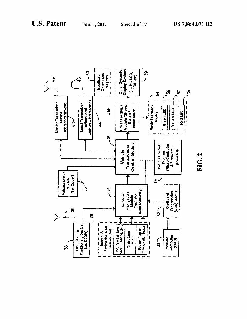
FIG. 2 is a block diagram of the functions in an emergencyvehicles is the ability to display much more useful data in the vehicle transponder for the preemption system.vehicles helping the vehicle operator maneuver his vehicle 40 FIG. 3 is an example schematic block diagram of a stan-most efficiently and safely. This data includes (but is not
dard vehicle transponder for the preemption system.
limited to) emergency-code levels, vehicle acceleration, FIG. 4 is an example schematic diagram of a vehicle on-vehicle type, and vehicle health. This method also enables
board diagnostic (OBD) circuit for the preemption system.feedback communication to be sent from the intersections to
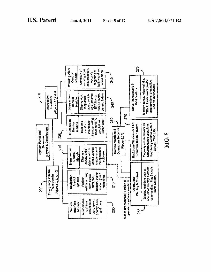
FIG. 5 is a functional organizational diagram of the threethe vehicles, providing vehicle-based warnings (or confirma- 45 major subsystems for the preemption system.tion) of system activity. Intersection "green" status shows
FIG. 6 is a schematic block diagram of the intersectionwhen an intersection has been preempted and priority is given
hardware for the preemption system, as configured for inter-to the receiving vehicle, allowing safe passage. If more than
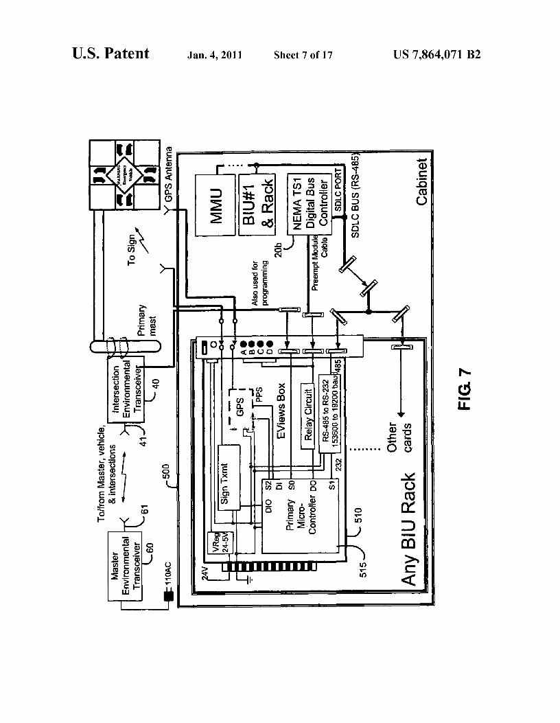
facing to an intersection controller without monitoring.one emergency vehicle approaches an intersection, the sys- FIG. 7 is a schematic block diagram of the intersectiontem determines which vehicle should have the right of way 50 hardware for the preemption system, as configured for inter-depending on location information (GPS, traffic loop, bea- facing to an intersection controller with digital BUS monitor-con, etc.), direction and speed sent to the intersection control. ing.A proprietary control program determines the right of way
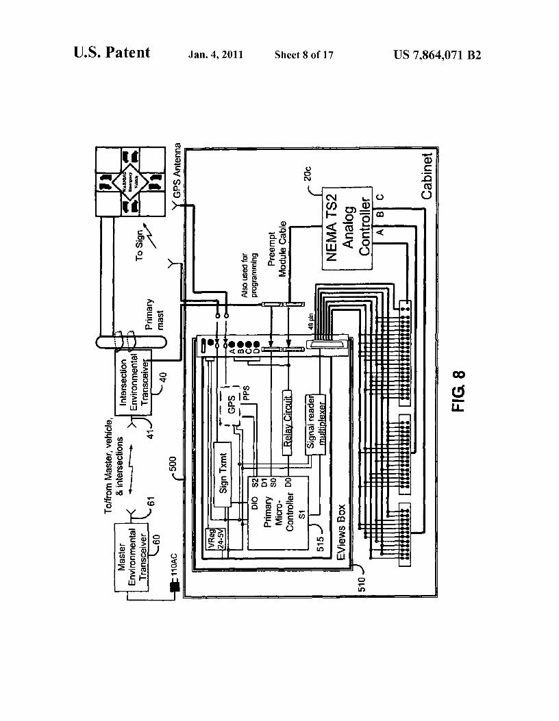
FIG. 8 is a schematic block diagram of the intersectionand sends the result to emergency vehicles. The encrypted
hardware for the preemption system, as configured for inter-
data package transmitted over transceivers is tagged with the 55 facing to an intersection controller with analog monitoring.vehicle ID and time to insure proper and certified utilization. FIG. 9 is a general flow diagram of the intersection control
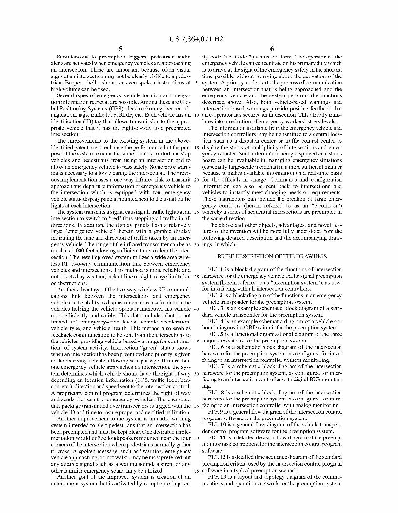
Another improvement to the system is an audio warning program software for the preemption system.system intended to alert pedestrians that an intersection has
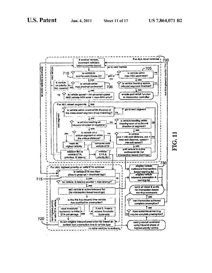
FIG. 10 is a general flow diagram of the vehicle transpon-been preempted and must be kept clear. One desirable imple- der control program software for the preemption system.mentation would utilize loudspeakers mounted near the four 60 FIG. 11 is a detailed decision flow diagram of the preemptcorners of the intersection where pedestrians normally gather monitor task component for the intersection control programto cross. A spoken message, such as "warning, emergency software.vehicle approaching, do not wall', may be most preferred but
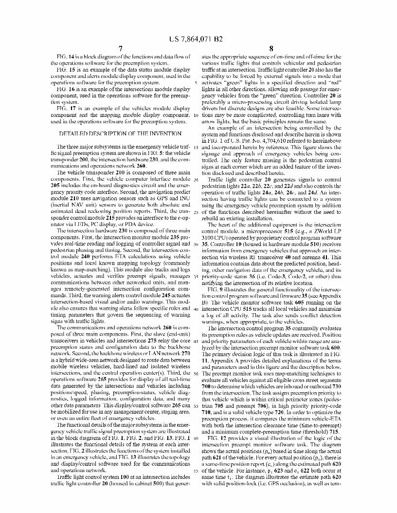
FIG. 12 is a detailed time sequence diagram of the standard
any audible signal such as a wailing sound, a siren, or any preemption criteria used by the intersection control programother familiar emergency sound may be utilized. 65 software in a typical preemption scenario.
Another goal of the improved system is creation of an
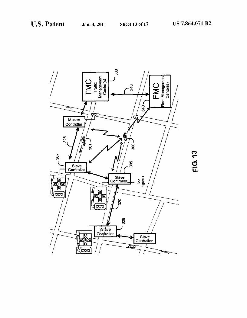
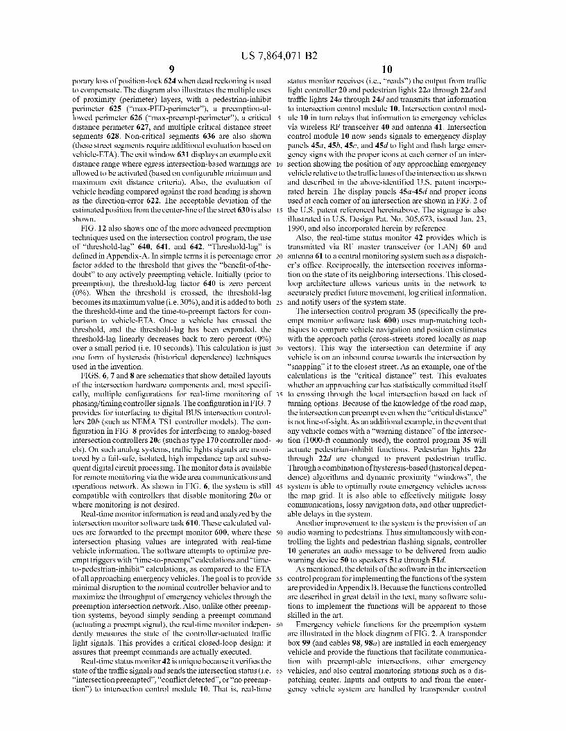
FIG. 13 is a layout and topology diagram of the commu-autonomous system that is activated by reception of a prior- nications and operations network for the preemption system.
US 7,864,071 B27
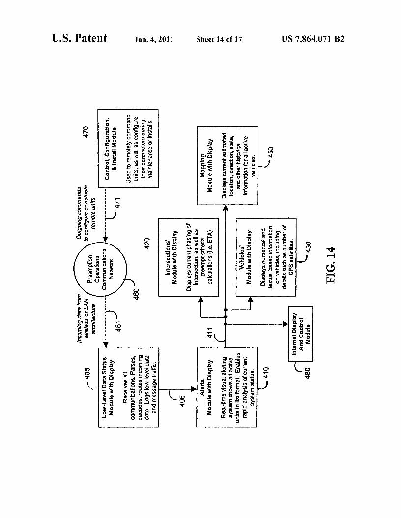
8FIG. 14 is a block diagram of the functions and data flow of
ates the appropriate sequence of on-time and off-time for the
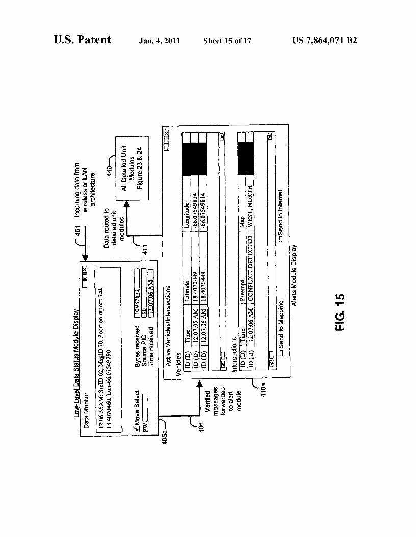
the operations software for the preemption system. various traffic lights that controls vehicular and pedestrianFIG. 15 is an example of the data status module display traffic at an intersection. Traffic light controller 20 also has the
component and alerts module display component, used in the capability to be forced by external signals into a mode thatoperations software for the preemption system. s activates "green" lights in a specified direction and "red"
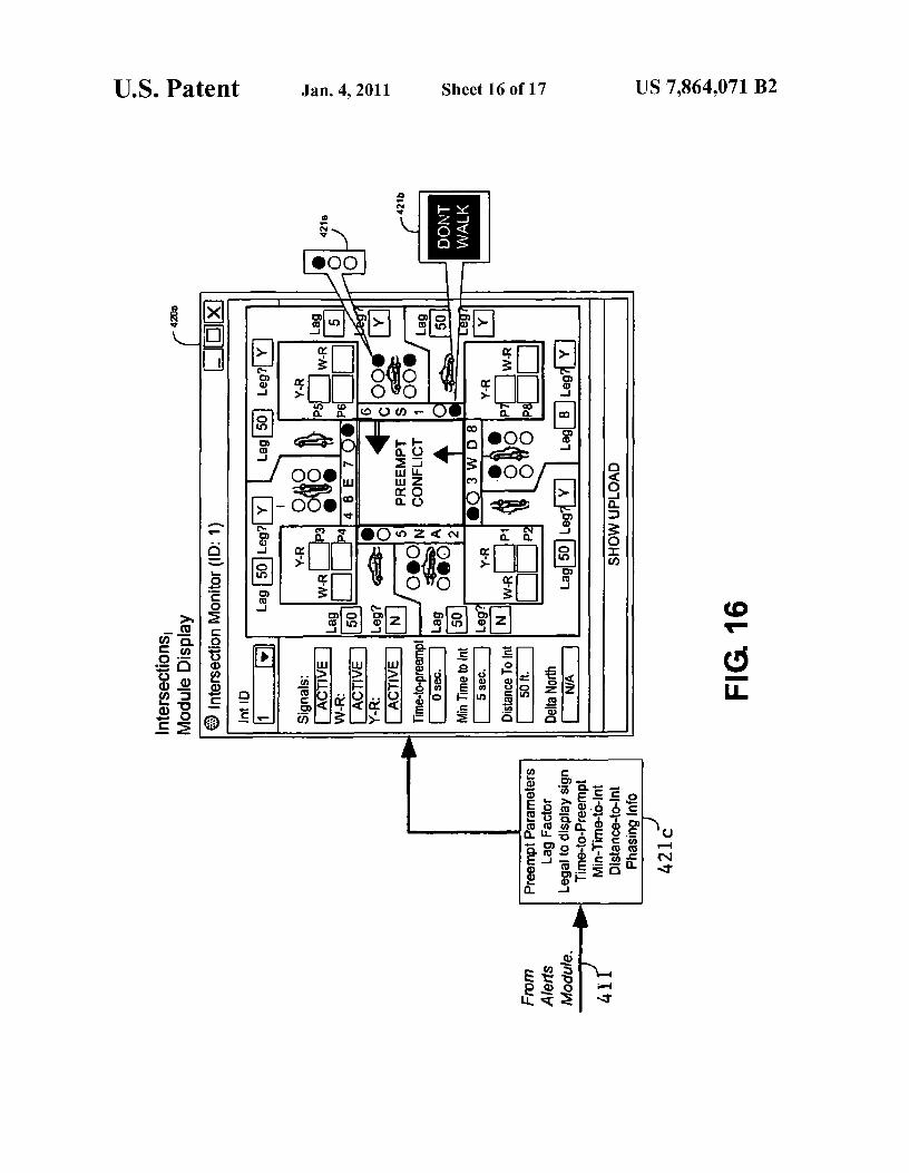
FIG. 16 is an example of the intersections module display
lights in all other directions, allowing safe passage for emer-component, used in the operations software for the preemp- gency vehicles from the "green" direction. Controller 20 istion system. preferably a micro-processing circuit driving isolated lamp
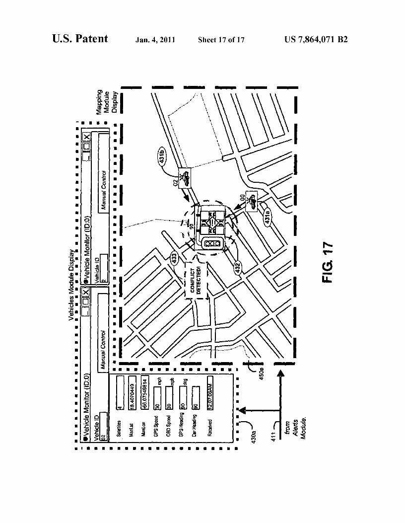
FIG. 17 is an example of the vehicles module display
drivers but discrete designs are also feasible. Some intersec-component and the mapping module display component, io tions may be more complicated, controlling turn lanes withused in the operations software for the preemption system. arrow lights, but the basic principles remain the same.
An example of an intersection being controlled by theDETAILED DESCRIPTION OF THE INVENTION system and functions disclosed and describe herein is shown
in FIG. 1 of U.S. Pat. No. 4,704,610 referred to hereinaboveThe three major subsystems in the emergency vehicle traf- 15 and incorporated herein by reference. This figure shows the
fic signal preemption system are shown in FIG. 5: the vehicle signage and approach of emergency vehicles being con-transponder 200, the intersection hardware 230, and the com- trolled. The only feature missing is the pedestrian controlmunications and operations network 260. signs at each corner which are an added feature of the inven-
The vehicle transponder 200 is composed of three main tion disclosed and described herein.components. First, the vehicle computer interface module 20 Traffic light controller 20 generates signals to control205 includes the on-board diagnostics circuit and the emer- pedestrian lights 22a, 22b, 22c, and 22d and also controls thegency priority code interface. Second, the navigation predict operation of traffic lights 24a, 24b, 24c, and 24d. An inter-module 210 uses navigation sensors such as GPS and INU section having traffic lights can be connected to a system(inertial NAV unit) sensors to generate both absolute and using the emergency vehicle preemption system by additionestimated dead reckoning position reports. Third, the tran- 25 of the functions described hereinafter without the need tosponder control module 215 provides an interface to the e-op- rebuild an existing installation.erator via LEDs, PC display, or PDA device. The heart of the additional equipment is the intersection
The intersection hardware 230 is composed of three main control module, a microprocessor 515 (e.g., a ZWorld LPcomponents. First, the intersection monitor module 235 pro- 3100 CPU) operated by proprietary control program softwarevides real-time reading and logging of controller signal and 30 35. Controller 10 (housed in hardware module 510) receivespedestrian phasing and timing. Second, the intersection con- information from emergency vehicles that approach an inter-trol module 240 performs ETA calculations using vehicle section via wireless RE transceiver 40 and antenna 41. Thispositions and local known mapping topology (commonly information contains data about the predicted position, head-known as map-matching). This module also tracks and logs ing, other navigation data of the emergency vehicle, and itsvehicles, actuates and verifies preempt signals, manages 35 priority-code status 36 (i.e. Code-3, Code-2, or other) thuscommunications between other networked units, and man- notifying the intersection of its relative location.ages remotely-generated intersection configuration com- FIG. 9 illustrates the general functionality of the intersec-mands. Third, the warning alerts control module 245 actuates tion control program software and firmware 35 (see Appendixintersection-based visual and/or audio warnings. This mod- B). The vehicle monitor software task 605 running on theule also ensures that warning alerts follow specific rules and 40 intersection CPU 515 tracks all local vehicles and maintainstiming parameters that govern the sequencing of warning a log of all activity. The task also sends conflict detectionsigns with traffic lights. warnings, when appropriate, to the vehicles.
The communications and operations network 260 is com- The intersection control program 35 continually evaluatesposed of three main components. First, the slave (end-unit)
its preemption rules as vehicle updates are received. Position
transceivers in vehicles and intersections 275 relay the core 45 and priority parameters of each vehicle within range are ana-preemption status and configuration data to the backbone lyzed by the intersection preempt monitor software task 600.network. Second, the backbone wireless or LAN network 270
The primary decision logic of this task is illustrated in FIG.
is a hybrid wide-area network designed to route data between 11. Appendix A provides detailed explanations of the termsmobile wireless vehicles, hard-lined and isolated wireless and parameters used in this figure and the description below.intersections, and the central operation center(s). Third, the 5o The preempt monitor task uses map-matching techniques tooperations software 265 provides for display of all real-time evaluate all vehicles against all eligible cross street segmentsdata generated by the intersections and vehicles including 700 to determine which vehicles are inbound or outbound 730positions/speed, phasing, preemption-status, vehicle diag- from the intersection. The task assigns preemption priority tonostics, logged information, configuration data, and many that vehicle which is within critical perimeter zones (pedes-other data parameters. This display/control software 265 can 55 trian 705 and preempt 706), in high priority priority-codebe mobilized for use in any management center, staging area, 710, and is a valid vehicle type 720. In order to optimize theor even an entire fleet of emergency vehicles. preemption process, it compares the minimum vehicle-ETA
The functional details of the major subsystems in the emer- with both the intersection clearance time (time-to-preempt)gency vehicle traffic signal preemption system are illustrated and a minimum complete-preemption time (threshold) 715.in the block diagrams of FIG. 1, FIG. 2, and FIG. 13. FIG. 1 60 FIG. 12 provides a visual illustration of the logic of theillustrates the functional details of the system at each inter- intersection preempt monitor software task. The diagramsection, FIG. 2 illustrates the functions of the system installed shows the actual positions (p #) based in time along the actualin an emergency vehicle, and FIG. 13 illustrates the topology path 621 of the vehicle. For every actual position (p #), there isand display/control software used for the communications a same-time position report (e#) along the estimated path 620and operations network. 65 of the vehicle. For instance, p, 623 and e, 622 both occur at
Traffic light control system 100 at an intersection includes same time t, The diagram illustrates the estimate path 620traffic light controller 20 (housed in cabinet 500) that gener- with valid position-lock (i.e. GPS occlusion), as well as tem-
US 7,864,071 B29
porary loss of position-lock 624 when dead reckoning is usedto compensate. The diagram also illustrates the multiple usesof proximity (perimeter) layers, with a pedestrian-inhibitperimeter 625 ("max-PED-perimeter"), a preemption-al-lowed perimeter 626 ("max-preempt-perimeter"), a critical 5
distance perimeter 627, and multiple critical distance streetsegments 628. Non-critical segments 636 are also shown(these street segments require additional evaluation based onvehicle-ETA). The exit window 631 displays an example exitdistance range where egress intersection-based warnings are ioallowed to be activated (based on configurable minimum andmaximum exit distance criteria). Also, the evaluation ofvehicle heading compared against the road heading is shownas the direction-error 622. The acceptable deviation of theestimated position from the center-line of the street 630 is also 15
shown.FIG. 12 also shows one of the more advanced preemption
techniques used on the intersection control program, the useof "threshold-lag" 640, 641, and 642. "Threshold-lag" isdefined in Appendix-A. In simple terms it is percentage error 20
factor added to the threshold that gives the "benefit-of-the-doubt" to any actively preempting vehicle. Initially (prior topreemption), the threshold-lag factor 640 is zero percent(0%). When the threshold is crossed, the threshold-lagbecomes its maximum value (i.e. 30%), and it is added to both 25
the threshold-time and the time-to-preempt factors for com-parison to vehicle-ETA. Once a vehicle has crossed thethreshold, and the threshold-lag has been expanded, thethreshold-lag linearly decreases back to zero percent (0%)over a small period (i.e. 10 seconds). This calculation is just 30
one form of hysteresis (historical dependence) techniquesused in the invention.
FIGS. 6, 7 and 8 are schematics that show detailed layoutsof the intersection hardware components and, most specifi-cally, multiple configurations for real-time monitoring of 35
phasing/timing controller signals. The configuration in FIG. 7provides for interfacing to digital BUS intersection control-lers 20b (such as NEMA TS controller models). The con-figuration in FIG. 8 provides for interfacing to analog-basedintersection controllers 20c (such as type 170 controller mod- 40
els). On such analog systems, traffic lights signals are moni-tored by a fail-safe, isolated, high impedance tap and subse-quent digital circuit processing. The monitor data is availablefor remote monitoring via the wide area communications andoperations network. As shown in FIG. 6, the system is still 45
compatible with controllers that disable monitoring 20a orwhere monitoring is not desired.
Real-time monitor information is read and analyzed by theintersection monitor software task 610. These calculated val-ues are forwarded to the preempt monitor 600, where these 50
intersection phasing values are integrated with real-timevehicle information. The software attempts to optimize pre-empt triggers with "time-to-preempt" calculations and "time-to-pedestrian-inhibit" calculations, as compared to the ETAof all approaching emergency vehicles. The goal is to provide 55
minimal disruption to the nominal controller behavior and tomaximize the throughput of emergency vehicles through thepreemption intersection network. Also, unlike other preemp-tion systems, beyond simply sending a preempt command(actuating a preempt signal), the real-time monitor indepen- 60
dently measures the state of the controller-actuated trafficlight signals. This provides a critical closed-loop design: itassures that preempt commands are actually executed.
Real-time status monitor 42 is unique because it verifies thestate of the traffic signals and sends the intersection status (i.e. 65
"intersection preempted", "conflict detected", or "no preemp-tion") to intersection control module 10. That is, real-time
10status monitor receives (i.e., "reads") the output from trafficlight controller 20 and pedestrian lights 22a through 22d andtraffic lights 24a through 24d and transmits that informationto intersection control module 10. Intersection control mod-ule 10 in turn relays that information to emergency vehiclesvia wireless RE transceiver 40 and antenna 41. Intersectioncontrol module 10 now sends signals to emergency displaypanels 45a, 45b, 45c, and 45d to light and flash large emer-gency signs with the proper icons at each corner of an inter-section showing the position of any approaching emergencyvehicle relative to the traffic lanes of the intersection as shownand described in the above-identified U.S. patent incorpo-rated herein. The display panels 45a-45d and proper iconsused at each corner of an intersection are shown in FIG. 2 ofthe U.S. patent referenced hereinabove. The signage is alsoillustrated in U.S. Design Pat. No. 305,673, issued Jan. 23,1990, and also incorporated herein by reference.
Also, the real-time status monitor 42 provides which istransmitted via RE master transceiver (or LAN) 60 andantenna 61 to a central monitoring system such as a dispatch-er's office. Reciprocally, the intersection receives informa-tion on the state of its neighboring intersections. This closed-loop architecture allows various units in the network toaccurately predict future movement, log critical information,and notify users of the system state.
The intersection control program 35 (specifically the pre-empt monitor software task 600) uses map-matching tech-niques to compare vehicle navigation and position estimateswith the approach paths (cross-streets stored locally as mapvectors). This way the intersection can determine if anyvehicle is on an inbound course towards the intersection by"snapping" it to the closest street. As an example, one of thecalculations is the "critical distance" test. This evaluateswhether an approaching car has statistically committed itselfto crossing through the local intersection based on lack ofturning options. Because of the knowledge of the road map,the intersection can preempt even when the "critical distance"is not line-of-sight. As an additional example, in the event thatany vehicle comes with a "warning distance" of the intersec-tion (1000-ft commonly used), the control program 35 willactuate pedestrian-inhibit functions. Pedestrian lights 22athrough 22d are changed to prevent pedestrian traffic.Through a combination of hysteresis-based (historical depen-dence) algorithms and dynamic proximity "windows", thesystem is able to optimally route emergency vehicles acrossthe map grid. It is also able to effectively mitigate lossycommunications, lossy navigation data, and other unpredict-able delays in the system.
Another improvement to the system is the provision of anaudio warning to pedestrians. Thus simultaneously with con-trolling the lights and pedestrian flashing signals, controller10 generates an audio message to be delivered from audiowarning device 50 to speakers 51a through 51d.
As mentioned, the details of the software in the intersectioncontrol program for implementing the functions of the systemare provided in Appendix B. Because the functions controlledare described in great detail in the text, many software solu-tions to implement the functions will be apparent to thoseskilled in the art.
Emergency vehicle functions for the preemption systemare illustrated in the block diagram of FIG. 2. A transponderbox 99 (and cables 98, 98a) are installed in each emergencyvehicle and provide the functions that facilitate communica-tion with preempt-able intersections, other emergencyvehicles, and also central monitoring stations such as a dis-patching center. Inputs and outputs to and from the emer-gency vehicle system are handled by transponder control

US 7,864,071 B211
12module 30 under the direction of proprietary control program as speed, acceleration, heading, ignition status, etc. and gen-software 15. Vehicle parameters are determined from several
erates the proper digital signals 96a for delivery to transpon-
inputs provided to transponder control module 30. der control module 30.Vehicle position is available from GPS receiver 38 via
FIG. 10 illustrates the general functionality of the vehicle
antenna 39. Several positioning inputs 96 are available from 5 transponder control program software and firmware. The pro-ports in navigation input device 34. Optional alternative gram monitors and logs all in-range vehicles and intersec-inputs from ports and navigation input device 34 are INU
tions and manages the data output to the operator display. The
(inertial navigation and estimation unit 29) parameters core component of the transponder software is the navigationincluding accelerometers, gyroscopes, wheel-tachometers, prediction module software task 655. The task uses positionand heading indicators. Other inputs include ID tag tracking, io estimates by GPS and other absolute position inputs, andbeacon triangulation, modified traffic loop detectors, and oth- combines data from accelerometers, gyroscopes, tachom-ers. Vehicle information such as speed and acceleration are eters, and heading indicators. This data is then integrated withread in real-time from the vehicle computer 33 using the
historical logs. This process, commonly known as dead reck-
on-board diagnostic (OBD) interface cable and connector oning, uses accurate (yet possibly intermittent) position33a. These signals are converted and verified by the OBD 15 reports integrated with time-based inertial navigation data tocircuit board 32 and the translated digital signals are input to generate enhanced position estimates. Position information istransponder control module 30 (embedded on a micro-con- forwarded to the transponder state and position monitor soft-troller 97). ware task 650. This task monitors vehicle state and diagnostic
The emergency vehicle transponder system communicates
inputs (such as Code-3) and generates position/state reportswith intersections via wireless RE transceiver 44 and antenna 20 to broadcast via the wireless network.45. The vehicles and intersections software task 670 running
FIG. 13 illustrates an example network topology for the
on the vehicle transponder handles incoming intersection communications and operations network. Emergencypreempt alerts and vehicle position reports from nearby units. vehicles 300 and 301 send navigation reports (i.e. GPS) andIt receives feedback verification and displays the information other data/commands (via wireless connection) to/from inter-on-board by activating one or more LEDs 56, 57, or 58 on the 25 sections and other local vehicles. Preemption-equipped inter-LED display 54. If it receives a signal for safe passage sections 305, 306, and 307 monitor navigation informationthrough an intersection, "green" LED 56 is illuminated. If
from vehicles. Intersections cooperatively and redundantly
another high-priority emergency vehicle is concurrently try- communicate with each other 320 (via wireless or LAN) toing to preempt the same intersection, "yellow" LED 57 is enhance data accuracy and ensure robust communications.illuminated. Illumination of "red" LED 58 indicates that there so Data is also passed along to existing TMC (traffic manage-is no preemption at the intersection. LEDs 56 through 58 are ment center) 330 using existing city LAN communicationsdriven by "intersection preempted" logic circuit 55. Logic network 325. If a LAN network is not used, wireless systemscircuit 55 can also provide customized outputs to dynamic can be substituted, such as through FMC 340 (fleet manage-display devices 59, such as PC monitor displays (LCD's) and
ment center) systems. From there, FMC can forward all data
Personal Digital Assistants (PDA's). Such devices are com- 35 to/from vehicle and TMC.monly used for law enforcement applications within the
FIG. 14 is a block diagram of the operations software,
vehicle. As mentioned, the operations software shown in FIG. designed for use in central command centers, mobile com-14 can be mobilized 80 and run on any vehicle-based auxil- mand stations, and in individual emergency vehicles. Theiary hardware device with a standard operating system. The
diagram illustrates the primary functional components of the
vehicle interface software task 665 in the transponder control 40 software. The primary components include algorithmic mod-program allows advanced mapping and alerting of active ules and visual displays for: low-level data activity 405, pri-nearby intersections and vehicles. ority alerts 410, intersections' data 420, vehicles' data 430,
Emergency vehicle status is available in real time via mas- and geographic mapping 450. In FIGS. 15, 16, and 17, bothter RE transceiver 64 and antenna 65 to a central monitoring
data and displays for these components are shown in an
station. Thus the position of any vehicle as well as the status 45 example preemption scenario. This example demonstratesat an intersection is always available at some centrally located
the real-time operations monitoring of a conflict detection
dispatch station. scenario, whereby two police vehicles are approaching theAs indicated previously, the software in control program same intersection in high priority mode. FIG. 15 shows
15 to implement the functions of the transponder described
incoming data 461 from vehicles and intersections within theabove has many possible solutions. Thus the software pro- 50 preemption operations communications network 460. Tex-vided to control the operation of transponder control module tual status messages are provided on the data status module30 can be designed and implemented by anyone skilled in the
display 405a. The data status module 405 also maintains a
art given the detailed explanation of the system and functions
historical record for all low-level communication and data-described hereinabove. Also, as previously mentioned, flow activity. This module 405 relays all verified and priorityAppendix B provides detailed pseudo-code of a full-featured 55 data messages 406 (i.e. position, preempt, and conflict mes-version of the software for both the intersection and vehicle. sages) to the alerts module 410. The alerts module display
FIG. 3 is a schematic block diagram of the transponder
410a provides real-time visual notifications of current high-system mounted in each vehicle. The transponder box 99 in priority events (i.e. active Code-3 vehicles and preemptedthe vehicle receives power from car battery through the OBD
intersections) and enables rapid analysis of the current pre-
interface 33a. The transponder box 99 has a GPS receiver 60 emption system status.such as that produced and manufactured by Garmin Interna- The alerts module 410 forwards all detailed data 411 to thetional Incorporated. The transceiver can be a radio transceiver vehicles and intersections modules 420 and 430. The inter-produced and manufactured by Freewave Technologies of
section module display 420a shows real-time detailed inter-
Boulder, Colo. section data including the traffic light states 421a (phasing)FIG. 4 is a schematic diagram of the on-board diagnostic 65 and pedestrian clearance states 421b. Also shown are timing
(OBD) circuit for the vehicle-based electronics and transpon- parameters 421c (for example, minimum ETA to intersectionder. The on-board diagnostic circuit handles such information
for inbound direction) and display data (for example, visual
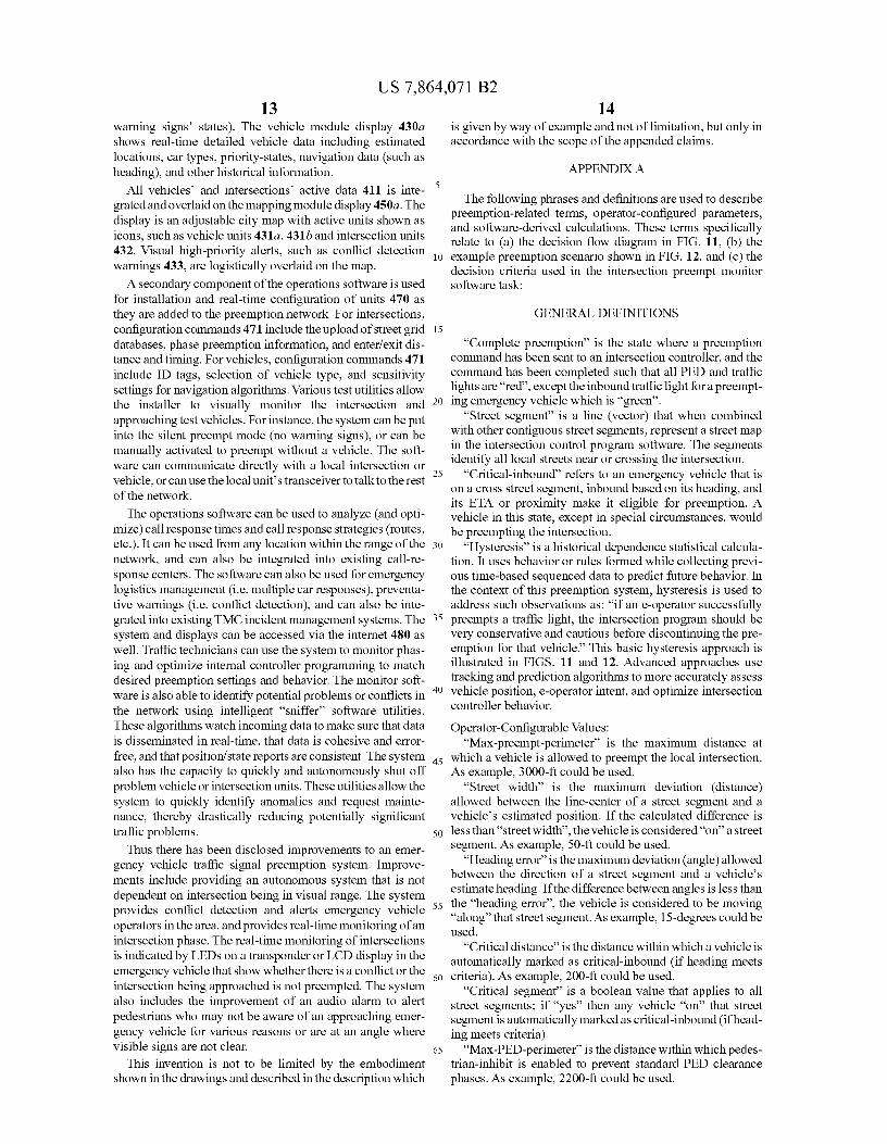
US 7,864,071 B213
warning signs' states). The vehicle module display 430ashows real-time detailed vehicle data including estimatedlocations, car types, priority-states, navigation data (such asheading), and other historical information.
All vehicles' and intersections' active data 411 is inte-grated and overlaid on the mapping module display 450a. Thedisplay is an adjustable city map with active units shown asicons, such as vehicle units 431a, 431b and intersection units432. Visual high-priority alerts, such as conflict detectionwarnings 433, are logistically overlaid on the map.
A secondary component of the operations software is usedfor installation and real-time configuration of units 470 asthey are added to the preemption network. For intersections,configuration commands 471 include the upload of street griddatabases, phase preemption information, and enter/exit dis-tance and timing. For vehicles, configuration commands 471include ID tags, selection of vehicle type, and sensitivitysettings for navigation algorithms. Various test utilities allowthe installer to visually monitor the intersection andapproaching test vehicles. For instance, the system can be putinto the silent preempt mode (no warning signs), or can bemanually activated to preempt without a vehicle. The soft-ware can communicate directly with a local intersection orvehicle, or can use the local unit's transceiver to talk to the restof the network.
The operations software can be used to analyze (and opti-mize) call response times and call response strategies (routes,etc.). It can be used from any location within the range of thenetwork, and can also be integrated into existing call-re-sponse centers. The software can also be used for emergencylogistics management (i.e. multiple car responses), preventa-tive warnings (i.e. conflict detection), and can also be inte-grated into existing TMC incident management systems. Thesystem and displays can be accessed via the internet 480 aswell. Traffic technicians can use the system to monitor phas-ing and optimize internal controller programming to matchdesired preemption settings and behavior. The monitor soft-ware is also able to identify potential problems or conflicts inthe network using intelligent "sniffer" software utilities.These algorithms watch incoming data to make sure that datais disseminated in real-time, that data is cohesive and error-free, and that position/state reports are consistent. The systemalso has the capacity to quickly and autonomously shut offproblem vehicle or intersection units. These utilities allow thesystem to quickly identify anomalies and request mainte-nance, thereby drastically reducing potentially significanttraffic problems.
Thus there has been disclosed improvements to an emer-gency vehicle traffic signal preemption system. Improve-ments include providing an autonomous system that is notdependent on intersection being in visual range. The systemprovides conflict detection and alerts emergency vehicleoperators in the area, and provides real-time monitoring of anintersection phase. The real-time monitoring of intersectionsis indicated by LEDs on a transponder or LCD display in theemergency vehicle that show whether there is a conflict or theintersection being approached is not preempted. The systemalso includes the improvement of an audio alarm to alertpedestrians who may not be aware of an approaching emer-gency vehicle for various reasons or are at an angle wherevisible signs are not clear.
This invention is not to be limited by the embodimentshown in the drawings and described in the description which
14is given by way of example and not of limitation, but only inaccordance with the scope of the appended claims.
APPENDIX A
The following phrases and definitions are used to describepreemption-related terms, operator-configured parameters,and software-derived calculations. These terms specificallyrelate to (a) the decision flow diagram in FIG. 11, (b) the
10 example preemption scenario shown in FIG. 12, and (c) thedecision criteria used in the intersection preempt monitorsoftware task:
GENERAL DEFINITIONS15
"Complete preemption" is the state where a preemptioncommand has been sent to an intersection controller, and thecommand has been completed such that all PED and trafficlights are "red", except the inbound traffic light for a preempt-
20 ing emergency vehicle which is "green"."Street segment" is a line (vector) that when combined
with other contiguous street segments, represent a street mapin the intersection control program software. The segmentsidentify all local streets near or crossing the intersection.
25 "Critical-inbound" refers to an emergency vehicle that ison a cross street segment, inbound based on its heading, andits ETA or proximity make it eligible for preemption. Avehicle in this state, except in special circumstances, wouldbe preempting the intersection.
30 "Hysteresis" is a historical dependence statistical calcula-tion. It uses behavior or rules formed while collecting previ-ous time-based sequenced data to predict future behavior. Inthe context of this preemption system, hysteresis is used toaddress such observations as: "if an e-operator successfully
35 preempts a traffic light, the intersection program should bevery conservative and cautious before discontinuing the pre-emption for that vehicle." This basic hysteresis approach isillustrated in FIGS. 11 and 12. Advanced approaches usetracking and prediction algorithms to more accurately assess
40 vehicle position, e-operator intent, and optimize intersectioncontroller behavior.
Operator-Configurable Values:"Max-preempt-perimeter" is the maximum distance at
45 which a vehicle is allowed to preempt the local intersection.As example, 3000-ft could be used.
"Street width" is the maximum deviation (distance)allowed between the line-center of a street segment and avehicle's estimated position. If the calculated difference is
50 less than "street width", the vehicle is considered "on" a streetsegment. As example, 50-ft could be used.
"Heading error" is the maximum deviation (angle) allowedbetween the direction of a street segment and a vehicle'sestimate heading. If the difference between angles is less than
55 the "heading error", the vehicle is considered to be moving"along" that street segment. As example, 15-degrees could beused.
"Critical distance" is the distance within which a vehicle isautomatically marked as critical-inbound (if heading meets
60 criteria). As example, 200-ft could be used."Critical segment" is a boolean value that applies to all
street segments; if "yes" then any vehicle "on" that streetsegment is automatically marked as critical-inbound (if head-ing meets criteria).
65 "Max-PED-perimeter" is the distance within whichpedes-trian-inhibit is enabled to prevent standard PED clearancephases. As example, 2200-ft could be used.
US 7,864,071 B215
"Min-exit-distance" is the minimum outbound distancepast which egress intersection-based warnings are allowed.As example, 30-11 could be used.
"Max-exit-distance" is the maximum outbound distanceup to which egress intersection-based warnings are allowed.As example, 100-11 could be used.
"Min-exit-speed" is the minimum speed above which out-bound intersection-based warnings are allowed. As example,5-mph could be used.
"Min-preempt-speed" is the minimum speed above whichinbound preemption and inbound intersection-based warn-ings are allowed. As example, 10-mph could be used.
"Max-latency" is the maximum time between preempt-able messages (see latency-counter description) from thesame vehicle before that vehicle is considered inactive. Asexample, 6-secs could be used.
Software Derived/Calculated Values:"Max-NAV-error" is the maximum estimated distance
error allowed for vehicle-ETA calculations, as determined bydead reckoning algorithms and positioning device specifica-tions. Any error exceeding this factor will invalidate the asso-ciated estimated vehicle position. As example, 150-ft couldbe used.
"Vehicle-ETA" is the minimum estimated ETA (estimated-time-of-arrival) of a vehicle at an intersection, as calculatedusing the real-time map distance between vehicle and inter-section, vehicle speed, vehicle acceleration (based on histori-cal averaging and vehicle type), street type, and expectedstreet conditions (i.e. time-of-day).
"Threshold-lag" is the minimum estimated time that thecomplete-preemption state must remain steady prior to a pre-empting vehicle's arrival at an intersection. This calculationis based on the vehicle's speed. The purpose of this factor isto minimize slowing of preempting vehicle. The lag includesthreshold-hysteresis (see below).
"Threshold-hysteresis" is a percentage time error includedin threshold-lag. When a vehicle preempts an intersection, thethreshold-hysteresis factor resets from 0% to a percentage ofthe initial vehicle-ETA. For example, 30% could be thedefault initial setting. Every second thereafter, this percent-age is reduced linearly, until 0%. This ensures that once avehicle is preempting, it is unlikely a temporary vehiclechange will disable preemption (i.e. slowing down).
"Time-to-preempt" is the minimum time to achieve com-plete preemption at an intersection, estimatedby the real-timephasing monitor. One of the primary calculations to deter-mine a vehicle's preempt eligibility is if a vehicle's ETA isless than the sum of the time-to-preempt and threshold-lagparameters.
"Latency-counter" is the number of seconds since the last"valid" preempt-able message was received from a givenvehicle. Some criteria that would cause the latency counter toincrement are: (a) a position report accuracy worse than Max-NAV-error, (b) vehicle not "on" a street segment, (c) low or novehicle speed, or (d) vehicle heading not inbound.
What is claimed is:1. An emergency vehicle traffic control system comprising:• processor; and• memory operably coupled to the processor and having
program instructions stored therein, the processor beingoperable to execute the program instructions, the pro-gram instructions including:receiving navigation information of an emergency
vehicle approaching an intersection equipped withone or more vehicular traffic lights;
16estimating a time of arrival at the intersection based on
the navigation information;transmitting one or more preempt commands for con-
trolling the vehicular traffic lights based on the esti-5 mated time of arrival and current light states of the
vehicular traffic lights for providing right of way tothe emergency vehicle;
verifying that the preempt commands have beenexecuted; and
10 transmitting a signal to the emergency vehicle based onthe verification for activating a visual display in theemergency vehicle indicative of whether the emer-gency vehicle has right of way through the intersec-tion.
15 2. The system of claim 1 further comprising:a warning alert control module at the intersection for acti-
vation of a warning message associated with theapproaching emergency vehicle.
3. The system of claim 2, wherein the warning message is20 a visual alert.
4. The system of claim 2, wherein the warning message isan audio alert.
5. The system of claim 1, wherein the program instructionsfurther include:
25 assigning a preemption priority to the emergency vehicle.6. The system of claim 1, wherein the program instructions
further include:transmitting a preemption status to the emergency vehicle.7. The system of claim 1, wherein the navigation informa-
30 tion includes emergency vehicle position data.8. The system of claim 7, wherein the position data is
derived from an inertial navigation unit.9. The system of claim 7, wherein the position data is
derived from a global positioning system.35 10. The system of claim 1, wherein the controlling includes
controlling one or more pedestrian traffic lights based on atime for a pedestrian to cross the intersection.
11. The system of claim 10, wherein the controlling of thepedestrian traffic lights includes inhibiting a pedestrian clear-
4o ance phase.12. An emergency vehicle traffic control system compris-
ing:• processor; and• memory operably coupled to the processor and having
45 program instructions stored therein, the processor beingoperable to execute the program instructions, the pro-gram instructions including:receiving navigation information of an emergency
vehicle approaching an intersection equipped with50 one or more vehicular traffic lights and one or more
pedestrian traffic lights;estimating a time of arrival at the intersection based on
the navigation information;controlling the vehicular traffic lights and the one or
55 more pedestrian traffic lights based on the estimatedtime of arrival and current light states of the vehiculartraffic lights and the pedestrian traffic lights for pro-viding right of way to the emergency vehicle; and
monitoring status of the vehicular traffic lights and the60 one or more pedestrian traffic lights for verifying pre-
emption of the vehicular traffic lights and the one ormore pedestrian traffic lights.
13. An emergency vehicle traffic control system compris-ing:
65 a processor; anda memory operably coupled to the processor and having
program instructions stored therein, the processor being
US 7,864,071 B217
operable to execute the program instructions, the pro-gram instructions including:receiving navigation information of an emergency
vehicle approaching an intersection equipped withone or more vehicular traffic lights and one or morepedestrian traffic lights;
estimating a time of arrival at the intersection based onthe navigation information; and
controlling the vehicular traffic lights and the one ormore pedestrian traffic lights based on the estimated
18time of arrival and current light states of the vehiculartraffic lights and the pedestrian traffic lights for pro-viding right of way to the emergency vehicle,
wherein the controlling of the pedestrian traffic lightsincludes inhibiting a pedestrian clearance phase, and
wherein inhibiting the pedestrian clearance phase includesdisabling a pedestrian call button.