
UNITED STATES PATENT OFFICE - nsa.gov
18
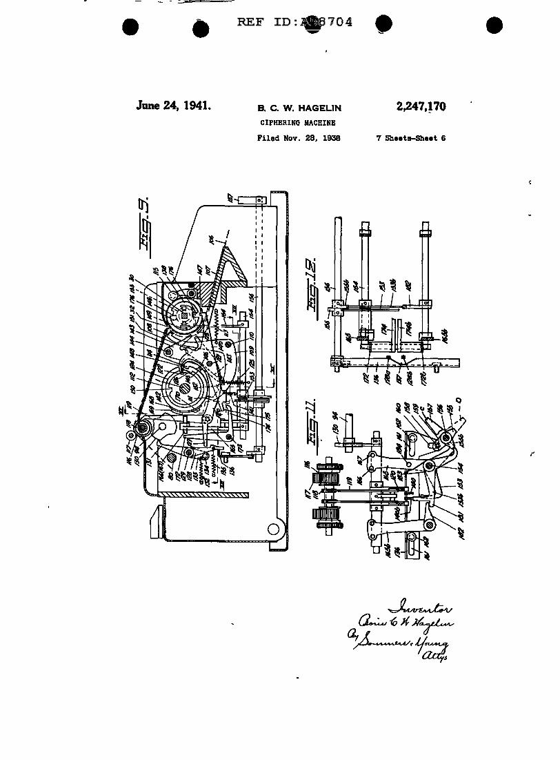
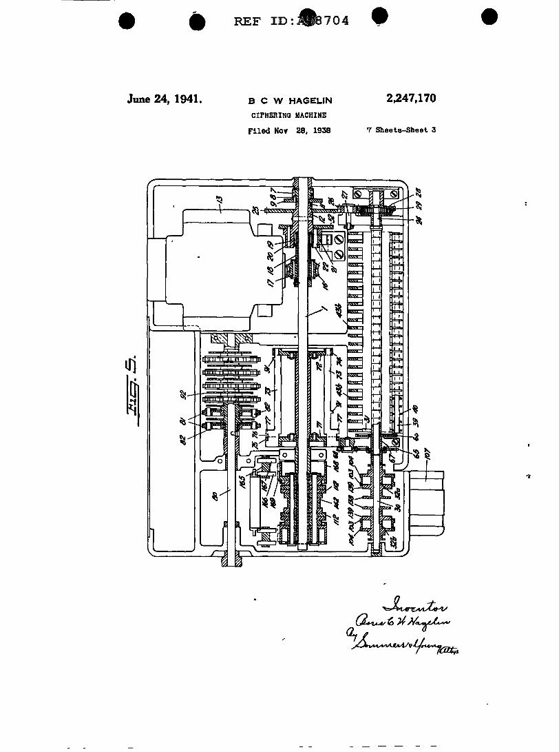
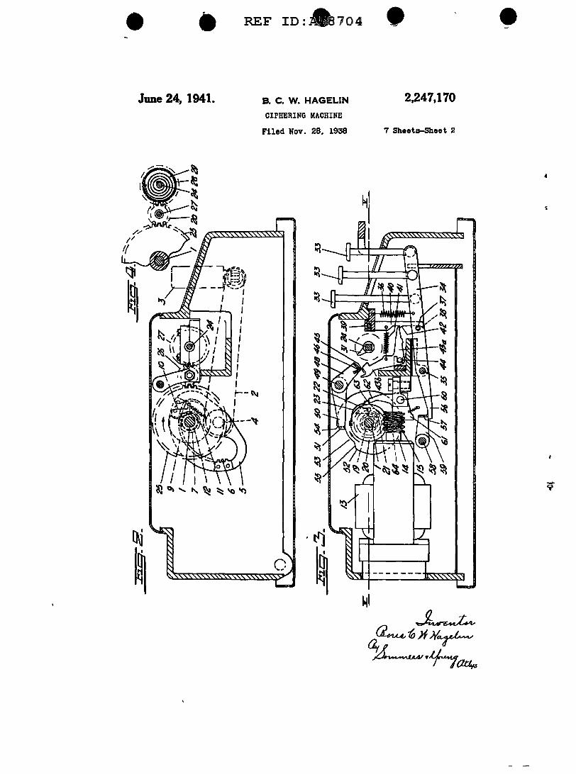
REF91>:A58704 - e Patented June 24, 1941 2,247,170 UNITED STATES PATENT 2,H7,171 CIPllEIUNG IU.CBINE Boris Caesar Wilhelm Bagelln, Stockholm, Sweden Appllca.ilon November !8, 1938, Serial No. HZ,833 19 CJalms. (CL 197--4) OFFICE The present mvenb.on relates to ciphering Fig 10 is a plan view of certain parts of the maclunes of the type m which the element car- printing device. Fig 11 ls an elevation. partly rymg the secondary signs <l e. the cipher si8ns in section, of parts of the printing mechanism. m ciphering and the clear text Signs in decipher- Fig 12 IS a horu.ontal section on the line XII- mg moves wit:i the element carrying the pnmary G XII of Fig 9 Figs. 13-19 show details of the signs U e. the clear text signs in ciphering and printing mechanism shown in ddferent pe>s1- the cipher signs in deciphering) when the latter tions for illustrating the operation 1s set to indicat.e a primary Sign, but is dis- The machine rests on a base plate forming placed after each such setting operation a part of the rlgld frame of the macblne and the number of steps which ls determined in every 10 vanous elements of the machine except the keJ'- mdlvidual case by mechanical means, before the board and certain controlling and readmg ele- readmg or printmg of the secondary sign, repre- ment.s a1e enclosed. in a casing having one or senting a cipher sign or the clear text Slgn, as mo1-e covers to render the mterior of the ma- the case may be, IS effected. In well-known chme easily accessible. ciphermg machmes of this type the primary la I indicates the main shaft of the machine signs are carried, as a rule, by o. rotatable disc wh1Ch extends in the transverse direction, as whlch 1S rotated by hand for indlcabng a pri- seen from the front of the machine. The main mary sign until the Slgn desired comes into shalt may be driven either manually or by a regJSter with an index ThlS rotation by hand suitable motor The manual driving means in- requU'es a great deal of observation and ls. thus, 20 eludes a crank 2 SJtuated at the right-hand end time-wasting, and an obJect of the invention or the machine which may be turned between is to provide a. setting device which may be a verb.cal and a honzontal position by means operated more rapidly and more rellably. An- of a handle a. In order that said handle may other obJect of the invention 1S to provide a reqwre a small space only, when the crank ls printing mechanism by which the primary or 25 in normal position, it may be swung upwards, the secondary text or both of them may be as shown in Fig. 2. printed. Purther obJects of the invention will The crank IS carril'd by a shaft 4 extending be apparent from the detailed description. parallel to the mam shaft. The connection be- The mvention is characterized, chiefly, by the tween the crank shaft 4 and the main shaft I fact that the ClPhering machme JS provided 30 comprises a frame & attached to the shaft 4 with a settmg mechanism controlled by a key- which JS formed with an mtemal toothed. arc board by which uPOn the depression of a key 6 engaged by a pinion 1 rotatably mounted on in order to indicate a primary slgn, a predeter- the mam shalt Said pmion is rigidly connected mined initial position JS fixed for the element as by pms I, Fig 5, to a dlSC S carrying a spring or elements carrymg the secondary signs, from a;; operated pawl II lnot shown m Fig, 1) for which position the displacement of said element engaging a tooth 11 formed on a hub 12 se- or elements takes place. The displacement may, cured to the main shaft As the crank Z is for instance, be of the type described in my turned from its vertical to its horizontal posi- U S Patent No. 2,089,603. tron, the dlSC 9 lS caused to perform one revo- In the accompanymg drawings a ciphering 40 lotion m the direction of the arrow, Fig. 2, caus- machine according to this invention ls illus- mg the pawl I I to move the tooth 11 and th.11S trated Plg. 1 is a plan view of the machine the hub 12 with the mam shaft through one with. certain parts removed and certam other revolution. Dunng the restonng of the crank parts shown m section Fig 2 ts a cross section from its honmntal to its vertical position which on the lme D-D of Fig. 1. Fig 3 ls a cross 45 may be controlled by a spring, if desired, the section on the line m-m of Fig. 1. Fig, 4 pawl ID slips around the hub 12 without moving 18 a detail view, in part sectional elevation, of same Upon the completwn of the revolution, the gearing between the main shaft and the the pawl comes agam into engagement with setting shaft of the machine. Pig. 5 is a hori- the top surface of the tooth 11. zontal section of the machine on the line V-V 60 The driVing motor consists in the example of Pig. 3. Pigs 6 and '1 are cross sections on shown of an electric motor 13 the shalt 14 of the lines VI-VI and VII-VII, respectively, of which, Fig 3, carries an endless .screw 15 In Pig. 1. Pig. 8 is an elevation, partly in section, mesh with a toothed wheel II rotatably mounted of part of the displacing mechanism. Pig. 9 on the main shaft. Ba1d toothed wheel ls rigid)y is a cross section on the line IX-IX of Fig. 1. 55 connected as by rivets. 11 to the hub 18 of a @'pproved for Release by NSA on 08-22-2014 pursuantto E.O. 1352a
Transcript of UNITED STATES PATENT OFFICE - nsa.gov

REF91>:A58704 - e Patented June 24, 1941 2,247,170
UNITED STATES PATENT 2,H7,171
CIPllEIUNG IU.CBINE
Boris Caesar Wilhelm Bagelln, Stockholm, Sweden
Appllca.ilon November !8, 1938, Serial No. HZ,833
19 CJalms. (CL 197--4)
OFFICE
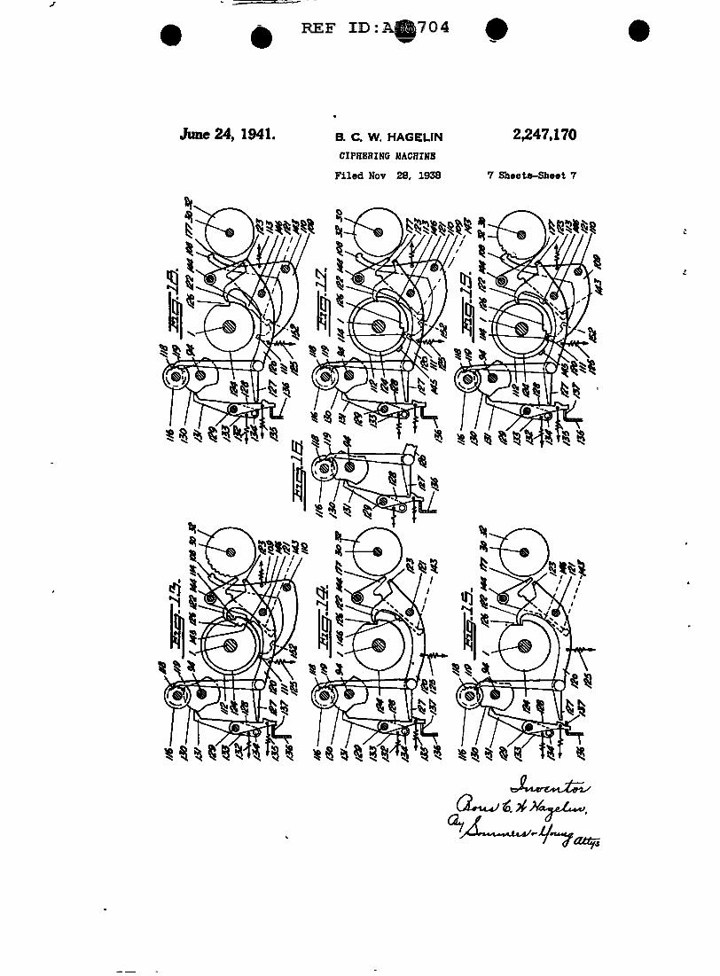
The present mvenb.on relates to ciphering Fig 10 is a plan view of certain parts of the maclunes of the type m which the element car- printing device. Fig 11 ls an elevation. partly rymg the secondary signs <l e. the cipher si8ns in section, of parts of the printing mechanism. m ciphering and the clear text Signs in decipher- Fig 12 IS a horu.ontal section on the line XII-mg moves wit:i the element carrying the pnmary G XII of Fig 9 Figs. 13-19 show details of the signs U e. the clear text signs in ciphering and printing mechanism shown in ddferent pe>s1-the cipher signs in deciphering) when the latter tions for illustrating the operation 1s set to indicat.e a primary Sign, but is dis- The machine rests on a base plate forming placed after each such setting operation a part of the rlgld frame of the macblne and the number of steps which ls determined in every 10 vanous elements of the machine except the keJ'-mdlvidual case by mechanical means, before the board and certain controlling and readmg ele-readmg or printmg of the secondary sign, repre- ment.s a1e enclosed. in a casing having one or senting a cipher sign or the clear text Slgn, as mo1-e covers to render the mterior of the ma-the case may be, IS effected. In well-known chme easily accessible. ciphermg machmes of this type the primary la I indicates the main shaft of the machine signs are carried, as a rule, by o. rotatable disc wh1Ch extends in the transverse direction, as whlch 1S rotated by hand for indlcabng a pri- seen from the front of the machine. The main mary sign until the Slgn desired comes into shalt may be driven either manually or by a regJSter with an index ThlS rotation by hand suitable motor The manual driving means in-requU'es a great deal of observation and ls. thus, 20 eludes a crank 2 SJtuated at the right-hand end time-wasting, and an obJect of the invention or the machine which may be turned between is to provide a. setting device which may be a verb.cal and a honzontal position by means operated more rapidly and more rellably. An- of a handle a. In order that said handle may other obJect of the invention 1S to provide a reqwre a small space only, when the crank ls printing mechanism by which the primary or 25 in normal position, it may be swung upwards, the secondary text or both of them may be as shown in Fig. 2. printed. Purther obJects of the invention will The crank IS carril'd by a shaft 4 extending be apparent from the detailed description. parallel to the mam shaft. The connection be-
The mvention is characterized, chiefly, by the tween the crank shaft 4 and the main shaft I fact that the ClPhering machme JS provided 30 comprises a frame & attached to the shaft 4 with a settmg mechanism controlled by a key- which JS formed with an mtemal toothed. arc board by which uPOn the depression of a key 6 engaged by a pinion 1 rotatably mounted on in order to indicate a primary slgn, a predeter- the mam shalt Said pmion is rigidly connected mined initial position JS fixed for the element as by pms I, Fig 5, to a dlSC S carrying a spring or elements carrymg the secondary signs, from a;; operated pawl II lnot shown m Fig, 1) for which position the displacement of said element engaging a tooth 11 formed on a hub 12 se-or elements takes place. The displacement may, cured to the main shaft As the crank Z is for instance, be of the type described in my turned from its vertical to its horizontal posi-U S Patent No. 2,089,603. tron, the dlSC 9 lS caused to perform one revo-
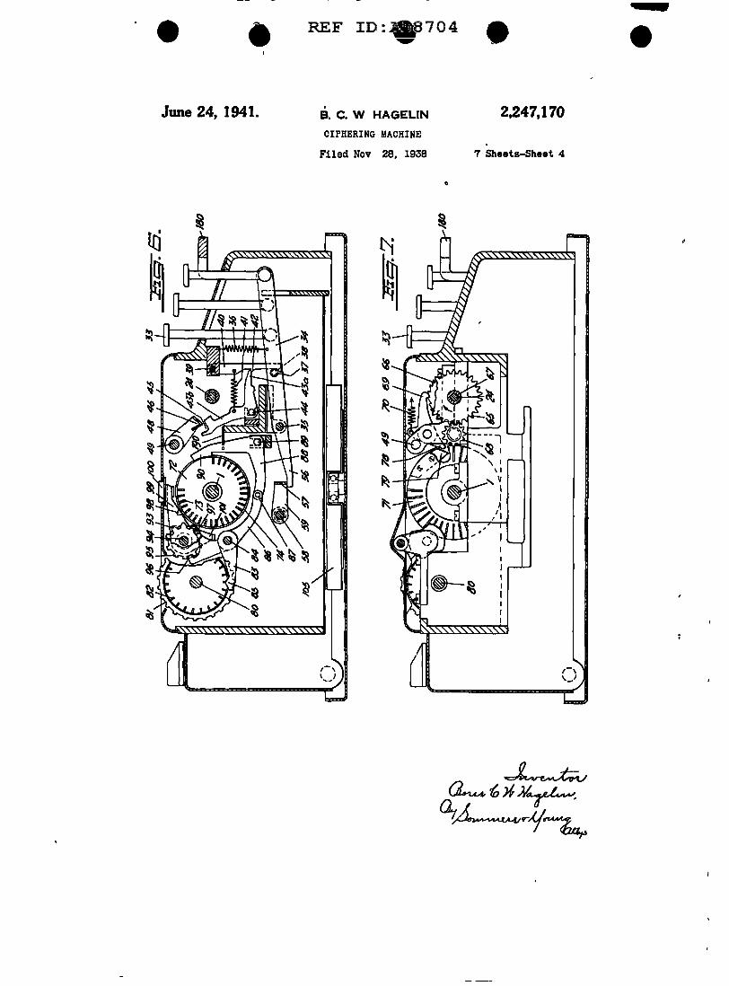
In the accompanymg drawings a ciphering 40 lotion m the direction of the arrow, Fig. 2, caus-machine according to this invention ls illus- mg the pawl I I to move the tooth 11 and th.11S trated Plg. 1 is a plan view of the machine the hub 12 with the mam shaft through one with. certain parts removed and certam other revolution. Dunng the restonng of the crank parts shown m section Fig 2 ts a cross section from its honmntal to its vertical position which on the lme D-D of Fig. 1. Fig 3 ls a cross 45 may be controlled by a spring, if desired, the section on the line m-m of Fig. 1. Fig, 4 pawl ID slips around the hub 12 without moving 18 a detail view, in part sectional elevation, of same Upon the completwn of the revolution, the gearing between the main shaft and the the pawl comes agam into engagement with setting shaft of the machine. Pig. 5 is a hori- the top surface of the tooth 11. zontal section of the machine on the line V-V 60 The driVing motor consists in the example of Pig. 3. Pigs 6 and '1 are cross sections on shown of an electric motor 13 the shalt 14 of the lines VI-VI and VII-VII, respectively, of which, Fig 3, carries an endless .screw 15 In Pig. 1. Pig. 8 is an elevation, partly in section, mesh with a toothed wheel II rotatably mounted of part of the displacing mechanism. Pig. 9 on the main shaft. Ba1d toothed wheel ls rigid)y is a cross section on the line IX-IX of Fig. 1. 55 connected as by rivets. 11 to the hub 18 of a
@'pproved for Release by NSA on 08-22-2014 pursuantto E.O. 1352a

...:::: --
• REF IJ:958704 e -2 9,147,170
ratchet wheel 19 bkewise rota.tably mounted on with one of the stop cams II on the setting shaft the main shaft I. The ratchet wheel 19 ls sur- 24. The stop arm 41b Is formed with a hooked rounded with a certain play by a sleeve-shaped end 45 to be engaged by a beam 41 extending par. flange 28 projectmg from the hub 12 which car- allel with the setting shaft which JS supJ>Orted nes a pawl 21 mounted at 22 and operated. by li by a palr of arms 41, 48 carried by a shaft 49 ex-a spring 23 which act.s to move the pawl into tending parallel with the main shaft The right engagement with the ratchet wheel 19 hand supporting ann 48 of the brldge aJso car-
The main shaft I Is connected by a power ries a rearwardly extending arm 51, Figs 1, 3, the storing geanng to a shaft 24 parallel with the free end of which is laterally bent, as shown at mam shaft which will be hereinafter referred IO & I, to bear on the periphery of a cam disc 12 to as the setting shaft Said gearing comprises on the main shaft I. Said cam disc 52 is formed a toothed wheel 25 attached to the main shaft with a recess 53 adapted to receive the bent end <cfr. Pigs. 1, 2, 4 and 5>, an intermediate toothed 51 which is bounded at one end by a radial sur-wheel 21 on a separate shaft 21 and a toothed face 14 correspanding to the plane front surface rim on a spnng housing 28 rotatably mounted IS of the bent end 51, and at the other end by a. on the settmg shaft 24. Saul spring housing sloping surface 55 <Plg 3) adapted to engage contatn.s a sPiral aprmg 29, Figs. 4, 5, surround- the rounded back of the bent end II. ing the shaft 24 the outer end of which Is con- Each key lever 34 IS formed with a rearwardly nected by a slip clutch to the spring housing 28, projecting arm 18 bearing against the under side whlle the inner end of the sprm.g Is secured 20 of an up and down movable beam 51 extending to the shaft 24. "l1us gearing permit.a rotabon parallel to the main shaft of the machine which of the mam shaft even lf 'the setting shaft 24 ls supported by arms &9 carried by a shaft 18, should be held against rotation. the Power de- likewise parallel with the main shaft Said beam hvered from the mam shaft being stored up In 51 fs adapted t.o act from below on a bell crank the spring 29 to be then utilized for rotating £j lever 11 mounted on the shaft H. Said bell the shaft 24 as soon as the latter Is released. crank lever comprises, m part, a stop arm 12 OWmg to the provlslon of the sllp clutch the adapted to engage a detent 13 on the coupling sprmg Z9 can only be put Under a predetermined pawl 21 and, lo pa.rt, a restoring a.rm 8' adapted Jll8Jdmum t.en.slon. to cooperate with the same detent in a manner
'1'he setting shaft 24 ls rotatably mounted in :;o to be hereinafter described ~e frame of the machine and ls connected at its The setting shaft 24 carries ln addition to the left hand end by a fixed or disengaging clutch dements already mentioned, a toothed wheel I& to a shaft It, hereinafter referred to as the and a ratchet wheel II <see Pigs. 1 and '1> both type wheel shaft, Situated in alfnement with of which are rigidly connected to the setting the setting shaft. The setting shaft carries a set 3j shaft, preferably by being carried by one and the of stop csms 31 for a purpase hereinafter stated eame hub 81. The toothed wheel 15 Is in mesh The type wheel shaft carries two type wheels 32a with a pinjon 18 carried by a separate shaft, and 12b, adapted to print the primary signs and and the ratchet wheel Is engaged by a pawl 19 the secondary SllDS, respectively. The same acted on by a spring 11. '1'he plnlon 18 and the a;igns, upally the twenty-SIX letters of the alpha- 40 pawl 19 are driven by a displacing drum carried bet, appear on both of the type wheel&, though by the main shaft Said displacing drum com-placed In the mutually reversed order. prises two end discs 11 and 12, respectively, at-
'l'he stop cams I I carried by the .setting shaft tached to shaft I and a set of axially extending IC are as maoy ID. number as there are letters on bars 11 carried by said discs which may be dls-each type wheel, f. e In the example under con- 4j placed ulally in notches formed in the end disc &ld.eration, twenty-six They are displaced pe- whlcb open a.t the periphery thereof. The bars rlpherally Jn the same way as the letters of the are .maintained In enpgement wtb said notches. i' type wheels, for lnStance, so that each tne wheel ln part, by a ring 1C surroundmg the disc 11 letter Is situated In axial reglsl;er with Its corre- and, In pa.rt, by an annular colled spring 11 sponding stop cam. 'lbe stop cams have for 50 placed around the disc 11 which engages notches their obJect to allow the setting of the type wheel 11 formed In the bars Sa1d. notches are such 6haft into positions corresponding to the prl- an ufal length as to allow the bars to perform mary signs bY means of a group of teya II (Fig, a certain axial displacement between two deft-1) of wbich there Is one for each tndivldual prl- nite end positions. In one of said end PoSitlons, mary sign and some additional ones for special 55 1. e. the normal position, shown in Pig 5, the left purposes. Each key Is pivotally connected at It.a hand end of the bars a.re situated in the same lower end to a lever 14 (Pigs. 3 and 6> situated plane as the outer surface of the disc 11. In the immedlate)J' above the base plate of the machine other end position, 1. e the working position, the which is movable In a vertical plane substantially left hand ends of the bars project beyond the disc at right angles to the shafts of the machine All c.o 11 : in said last-mentioned position, the project-of the levers H are Journalled on a common Ing ends may act as teeth In mesh with the pJn-sha.ft I&, but every lever is acted on by it.a Inell- Ion II vldual spring H tending to keep the key In Its Each bar 11 ls provided with an abutment 11 raised Position. At a point. between the key and on the right hand end of the notch 16 for releas-said shaft II the lever 14 carries a roller 11 on 11.> Jng the pawl H. Jn the normal Position of the a laterally' projecting stud. Bearing against this bars said abutments are situated out of reach of roller ls an oblique surface 38 formed at the lower the pawl 81; in the projected l. e working, posi-end of a depending arm 40 Journalled at its up- tlon of the bars, on the contrary, the abutments per end, as shown at H. A spring 41 acts on said may engage a rearwardly extending arm 18 arm to maintain the obllque surface thereof in ;o <Fig 7> of the pawl II ln order to Jlft the pawl contact With the roller 11 The depending ann out of engagement with the ratchet wheel H 41 is further formed with a stop 42 to be en- In addition, the disc 11 ls provided with a lat-gaged by the free end of one arm 414 of a bell erally proJectlng cam 11 adapted at the be-crank lever Journalled at 44, the other arm 41b ginning of each rotabon of the drum from its of which constitutes a stop arm for cooperation 'lo normal pasltlon to operate said arm 18 In order
- - ~
REF 8:A58704 -2,847,170 3
to release the pawl B9 already after a very small to the product of the numbers of teeth of all of rotation of the drum. the toothed wheels. Meshing in each toothed
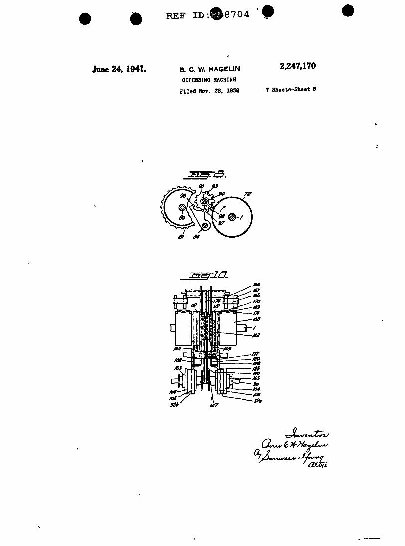
For effecting the settJ.Dg of the bars JI into wheel 92 fs a plnion II carried by a shaft M workJng .P0S1t10n there is a set of "key-wheels" common to all of the pinions 13. The pmiODS smular in construction to those described 1n my 6 H a.re all rigidly secured to shaft 94 and all of Patent No. 2,089,603 above referred to. The key- them h&ve the same number of teeth, thougb wheels &1e rotatably mounted on a fixed shaft their cl1ameters are ditlerent as determined by ID extend.mg parallel with the main shaft Each the different sizes of the toothed wheels 9Z. key-wheel 81 carries an annular set of axially A nwnber of signs <not shown>, as for in-shiftable pins 82 mounted 1n axial apertures ad- 10 stance, the letters of the alphabet, appear upon Jacent the perlp~ of the key-wheel which the penpheral portion of ea.ch key-wheel II, may be shifted individually so that they project said letters being visible through apertures beyond one lateral surface of the key-wheel or formed 1n the cover of the machine to indicate the other. ~ In Fig. 5 I have .shown a rear pin of the position of the key-wheels. In order to
II the extreme left hand keJ'-wheel slufted to the 11 facilitate rotation of each 1ndl.v1dual key-wheel left and a front pin of the same key-wheel by hand, the key-wheels a.re provided with shifted to the ngb.t. In one of said positions the tooth-like projections on their peupheral por-pJus arc out of operation, In the other position Uon, as shown in Figs. 6 and 8. they are adapted to trip levers II (Fig. 6> of The shaft 84 also carries & ratchet wheel 15, which there is one for each key-wheel, said leve1'S to Figs. 1. 6 and a. provided with as many teeth being .situated close by the respective key-wheel as there are teeth on each Pinion II. The pJn-on one side thereof. The levers II are rotatably ion 91 ls engaged by a pawl 18 provided with a mounted on a shaft 14. Each of them. carries release arm Bl to be acted on by a tooth II on at its free end a wedge-shaped cam 85 project- disc 12. The pawl 15 may also be released lng Into the path of the Pins sblfted to the cor- 11 manually by means Of & lever 19 CPJg. 6) carr:v-respondmg side of the respective key-wheel. The Ing a knob IDD for its operation. The release lever lS rigidly connected bY its hub to an arm lever 19 IS provided with a rearwardly extending II extending below the displacing drum which arm ID I bearing on arm 11. The tooth II also IS pivoted at 81 to a bell crank lever II mount- acts to rot.ate the pinion 83 situated 1n register ed. at 81. Bald bell crank lever surrounds a por- ao therewith, that ls, the extreme nght hand Pln-tion of the circumference of the dJsplacing drum Ion, t.o the extent ol one tooth pitch during each and carries at its upper end an &Xlally beveled complete revolution of the displacing drum. surface 81. Each aueh beveled surface ID IS Connected with shaft H is a counting mccha.-adapted to be engaged by abutments II or ccr- nlsm ID2. tam bars 13 in a W&J' to be hereinafter described. 31 The operation Of the setting and displacing In the example illustrated the beveled surfaces mechanisms above described IS as follows 80 are located in the path of the respective abut- The machine ls first ad.lusted, in order to b1Jng ments 11, when the corresponding cams 85 are it into correspondence with other :machines ol not act.ed on by pins 82 <that is to say, when the same type, so as to function on a certain pre-they are passed by pins shifted to the left>. or 49 detel'Dllned system. To this encl some or the course, the arrangement may also be the re- pins 82 of the key-wheels 81 a.re shifted to the verse, If desired. The abutments 11 may either left and others to the right ln an order agreed on be flxed, as for Instance, formed integrally with by the operators The key-wheels are then ro-the bars, as shown 1n the drawings, or shffted tated by hand until certain signs, bkewiSe pre-to different points of the bars. To this end the '6 viousJy agreed on, appear in corresponding aper-bars may be formed. with several notches or tures in the cover of the casing projections for :fixing the positions of the abut- In operation, whether for ciphering or de-
:; ments, which may :In such Cl&Se be saddle- ciphering a message, the prunary signs are in-shaped. Each bar 13 carries one abutment 81. dlc&ted by depressing the respective keys, sign The abutments of the 'Val'lous bars are arranged 60 by sign. After each depression the main shaft in groupg in register with the various beveled f fs rotated one revolution either by ope1 atlng surfaces 91. The number of bars belonging to the hand crank 2 or by transm1s.'>lon of power the individual groups should, preferably, be so from the motor 13. chosen as to allow any desired number of bars, Normally, the setting and dlsplacmg element.a that ls to say, from one to the total number of 51 are m the positions shown in the drawmgs. The bars, for instance twenty-six, to be displaced to main shaft I IS held against rotation by the stop the left, i e into operative position, under the arn1 &2, and the bell crank levers C3a, 43l> are mftuence of one or more or all groups or abut- held against movement by the stopi. C2 of the ments. The levers Bl are prevented from lateral arms CD, with the arms C3l> ln their retracted movements by a stationary comb-shaped guldmg 80 position The ,depressing of a key 33 causes the member I 9D. respective lever H to swing downwards, while
Rotatabl:v mounted on the shaft 8D ad,Jacent 1tsrear arm H moves upwaids When thus mov-Pach key-wheel IS a toothed wheel 12 connected ing downwards the lever 34 by its roller 31 act.~ to the respective key-wheel by & clutch, not on the obliqup surface H or arm 40, thereby shown, which causes the toothed wheel to par- 8G bringing the stop CZ out of engagement with the take of the rotation of the key-wheel m one d1- arm Cla of the bell crank lever Cla, b When rection but permits independent rotation of the thus released the stop arm Clb of the bell crank toothed wheel in the opposite direction The lever IS moved forwards by the action or spring toothed wheels 12 have each & different number Cl so as to enter the path of the rf'spe~t1ve stop of teeth. Said numbers are chosen so that they 70 cam 31 In its upward movement the arm 56 represent, as far as PoS&lble, prune factors or lifts the beam &1, which in fts turn lifts the at any rate have no common denominator fn lever 81, causing the stoparm 82 to ielease the order that the key-wheels may return to their dPtent 63 and bnnglng the restoring arm 84 Into original starting Position only after a very long the path of the detent 63. When thus released perlocl of step-by-step movemf'nt, corresponding 75 by the stop arm 12, the coupling pawl 2 I is moved
-~ - -
• REF 1~8704-
4 9,1147,170
by its spring 23 Into engagement with the ratchet restoring arm H, whereas the other functions wheel 19, thereby coupling the ma.in shaft I to to be derived from the main shaft take place the motor 13 The main shaft now starts ro- during the remaJning portion of the rotation. tation in the direction of the arrow, Fig 3, by If as the det.ent 63 strikes the restoring arm power derived from the running motor When I H, the key depressed has not yet been released, the det.ent 63 passes the restoring arm H, the the arm H cannot yield under the action of the lever 81 IS again swung down towards the beam pressure exerted by the detent 83 bUt will engage 11 which has been lowered in the meantune as same, thereby checking the rotation of the main a result of the release of the depressed key. At shaft. Only after the key is released the detent the same time the stoparm 82 again enters the JO 63 may force the restoring arm H aside, allow-path of the detent 83 Upon the completion of ing the main shaft to continue its rotation, until the revolution of shaft I, the stop arm 62 catches upon the completion of the revolution it Js the detent 63 and moves the coupling pawl 21 checked by the detent 13 engaging the stop out of engagement with the ratchet wheel 19, arm 82. thereby interrupting the transmission of motor 15 During the said first portion of the rotation of power to shaft I In case of manual operation, the main shaft, that is, while the detent 63 moves the couplmg pawl 21 does not act as a driver between the stop arm 82 a.nd the restoring arm because In this case the power is dlrect}J' lm- H, the proJectlon 11 remains in contact with the parted to the main shaft which ls caused to bottom of the recess &3 During this portion of perform one complete revolution by moving the 20 the rotation the beam H will, therefore, remain crank up and down one time, as alreadY de- In the position shown In which the stop arm 43b scribed per se In this case the pawl 21 only maintains the setting shaft 24 in the position acts to stop the main shaft In its fixed normal or corresponding to the primary sign depressed starting pOSition. During the continued rotation of the main shaft
In the beginning of the rotation of the main 25 the projection 11 ls lifted by the sloping edge &5 shaft the rear arm 18 of the pawl 69 is engaged of the recess 53, causing the beam. 48 to swing by the lateral cam 19 of the left hand disc 11 of rearwards so as to bring the st.op arm 4311 out of the displacing drum and lifted out of engagement engagement with the stop cam 31, the arm 43a with the ratchet wheel 88 so as to release the moving at the same time upwards towards the setting shaft 24 By power stored up in the 30 stop 42 of the arm 4D As the pro.Jection 11 setting shaft's driving spring 29 as a result of a reaches the cylindrical outer periphery of the dJ.sc previous rotation of the mam shaft, the setting 12, the arm 4311 comes into contact w1th the up-shaft 24 is rotated In the dll'ection of the arrow, per face of the stop 41, thereby again checking F'l.gs 3 and 7. until that stop arm 43b which has the lever 4311, b in Its normal position shown In been set to stop position by the depression of 35 F'l.g 3. In the meantime the pawl 89 has been the key, 1S engaged by the respective stop cam held in released state, because its rear arm 18 a I By said engagement the setting shaft lS held has been in contact with the cylindrical surface in a position co1respondmg to the sign of the of the dlSC 18 When the stop arm 4311, b is key depressed Due to its connection with the released bY the beam 46, the arm 18 leaves the sett.ng shaft the type wheel shaft has performed 40 said cylindrical surface, allowing the pawl 69 to exactly the same rotation as the setting shaft again engage the ratchet wheel 86 under the On the right hand type wheel 3211, whleh Js action of 116 spnng, thereby locking the shaft 24 adapted to indicate the primary signs, the sign In Its set position During the said continued In question now appears m printing posit10n. rotation of the main shaft, that Is, while the The seconda1y sign of the left hand typewheel 4;; detent &I is moving from the restoring arm 64 32a appearing In printing pOSJtion ls determlned to the stop arm 62, the bars 13 of the displacing by the fact that the alphabets or the two type drum, which are only provided within a portion wheels are arranged in mutual reverse order of the circumference of the drUm corresponding Prmtlng of the primary sign may, if desired, be to the angular extension of said continued rota-effected by aid or a mechanism to be described 50 tlon, enter the range where they can be inftuenced later on by the beveled surfaces 91 Those beveled sur-
In the above said stop position of the stop arm faces 91 which are in operative position will effect 43b the hooked end 41 thereof bears against the a displacement to the left Of those bars, the abut-beam 46 which is in the P<1S1t1on shown in Fig ments 91 of which are acted on bY the leveled 3 1n which position the lateral projection II of 65 surfaces 81 set to operative position The left the arm 50 is 1n engagement with the recess 53 hand ends of said bars wlll, therefore, project be-in the disc &2 whlle bearing against the radial yond the left hand disc 11 of the drum so as to end sui race 54 thereof act as teeth me.shlng with the pinion 68 Con-
The rotation of the settmg shaft 24 above de- sequently. said pinion during the sald rotation of scribed to effect the setting of the prunary Sign 60 the drum will be rotated as many tooth pitches is completed during the first portion of the rota- as there are bars 13 displaced to the left The tion of the primary shaft, inasmuch as the cam pinion 68 causes the toothed wheel 85 to make a 19, as me11tioned, at the very beg1nnmg of the corresp0ndmg rotation As said toothed wheel rotation of the main shaft llfts the pawl 69 out is attached to the setting shaft 24 and the latter or engagement with the ratchet wheel &8, thereby 65 is rigidly connected to the type wheel shaft the relea&lng the silo.ft 24, allowing It to be then ro- type wheels will be rotated correspondingly tated independently of the main shaft by power After this rotation or displacement the sign of stored up In the sprmg 29 as a result of a prior the secondary type wheel 32b which in the ex-rotatlon of the main shaft In order to allow ample under consideration constitutes the cipher the set.ting shaft to travel its entire path of ro- 70 sign corresPonding to the primary eign indicated tat1on, that ls, up to a complete revolution,, by depressing the key. is now in the printing posi-before any fw ther function is derived from the tion Each time the pinion 18 ls rotated to the main shaft. the operation· of the setting shaft extent of one tooth pitch under the control of a takes place during the movement of the detent bar 11, the pawl 69 is released by the action of the 83 of the pawl 21 from the at.op arm 12 to the 76 abutment 11 of said bar 1lPOD the rear arm 18 of
i
...
REF.:A58704
9,947,170 5 the pawJ The shaft 2.1 iS now released to allow a way to be hereinafter descnbed. 'lbe feed cam the rotation of the toothed wheel H Each time is provided with a. recess 128 so placed as to pass the toothed wheel &I ls moved one tooth the pawl the arm 122 Immediately before the main abaft &9 again engages the ratchet wheel 16, so tha.t the completes lt.s revolution. The arm IZZ will then type wheel shaft cannot move more than one Ii at once engage the recess to be thereafter grad-tooth pitch at a time. ThUfl, any unintentional ually lifted onto the Cll'cular portion of the rotation of the type wheel shaft ls positively pre- peripheey of the disc I H Dunng this movement vented. the pawl 111 is fint lowered rapidly a.nd lifted
The displacement of the type wheel sha.ft being more slowly while turning the ratchet wheel 118 completed, a printing of the c1pher sign Is effected 10 and the feed roller 116 a certain extent. Nor-
•i during the last position of the revolution of the maJJy, the movement of the feed lever 120 Is main shaft, after all of the bus of the displacing checked so tha.t it JS only allowed to move half drum have passed the position wllere they may the way that corresponds to the depth of the be engaged by the beveled displacing surfaces ID recess 126 of the feed cam I 24. Due to this cbeck-
Tbe mechanism for eff~ting the printing 15 Ing action the pawl I f9 Is lowered to an extent operation Is now to be described somewhat greater than the tooth pitch of the
As already stated, there arf' two type wheels ratchet wheel 111, and as a result the feeding of Ha and Hb, the former U e the right band the paper strip wm correspond to one tooth pitch. one> being adapted for printing the primary The tooth pitch is so dimensioned as to allow signs and the latter U e the left hand one> for 20 the paper strip to be fed by steps equal to the printing the secondary signs Each type wheel normal letter pitch In order to obtain the said is provided with two circular rows of types on its checking of the feed motion the feed lever 121 peripheral portion, one row, 181, containing the ls provided with a rearwa.rd.ly extending arm 121 twenty-six letters of the alphabet and the other cooperating' with a hook shaped stop arm 128 on row, IH, containing other signs, as figures, 2S the shaft 129 Flg. 13 shows the main shaft In punctuation marks and so on its starting position and the feed pawJ 111 In Its
The printing mechanism includes for each type uppermost position upon the completion of a wheeJ Ha or Hb a paper supplying reel 115, Flg feedlDI' step 6, placed In the lowermost portion of the machine In the printing of a cipher text It ls desired, as Prom said paper reel a strip of paper IOI ls led 30 a rule, to automatically divide the text into through guiding means. not shown, up into a groups, each of which comprises five letters. To guldeway 111, Flg 9, below the type wheels and effect this "five division" the paper strip is fed further up between thf' respf'ctive type wheel and to the extent of two tooth pitches after each a printing hammer IDI adapted t.o press the strip fifth printing operation To control this five dl-of paper against the type to be printed The 35 v.lsion I use a dlv.lsion cam I 10 rigidly mounted printing hammer comprises one end of a beJJ on the shaft 14 of the plnlons II Said cam Is crank lever 109 mounted on thf' shaft I ID which provided with two diametrically oppo.slte recesses is provided at its other end wlth a projection 111 on its periphery Pulled against the divtslon disc bearing against a cam disc 112, the printing cam, under the action of a spring 132 secured to a de-on the main shaft The l~r Ill Is mfluenced 40 pending catch arm 133 is an upwardly directed by a spring 111 tending to pull the printmg ham- arm Ill rigidly mounted on the shaft 129, here-mer against the type wheel and the proJectlon lnafter called the division arm. A laterally pro-111 against the printing cam 112 The printing Jecting pin 134 on said arm 133 is mtuated behind cam ls provided w!th a recess 114 adapted to re- the stop arm 128. A spring 131 acts to pull tbe ceive the projection 111 one time during each 45 stop arm 128 against said pin. When the upper revolution of the main shaft, the projection be- end of the divtston arm 131 fs in conta.d with Ing caused to engage said recen under the action the circular J)OJ'tlon of the periphery of the dlvi-of the spring 113 When this operation takes slon cam llD, then the catch arm 131 moves the p]ace the printing hammer 118 presses the paper stop arm 128 to the stop position above referred strip against the type wheel, the printing opera- 50 to, in which position the rear arm 121 or the tlon, cfr Fig. 19 Inking of the types Is effected feed lever Is checked by the stop arm aft.er it has by an inking roller I I& The recess 114 in the moved only to baJf the ext.ent or its lull stroke, printing cam 112 should, of course, be placed so as shown In Pig 14. In the two positions appear-that, when the main shaft starts its rotation due Ing at every fifth printing operation, I. e. when to the depression of a key. the recess 114 wm not 55 the dlvls!on arm engages the recesses Of the ll8S8 the prmting projection 111 untll after the division cam, the catch 133, 13C Is moved rear-type. wheel has reached the printing position wards so as to release the stop arm 128 and al-desired low it to be puJled back by Its spring II&; thus
In order to feed the paper strip through the the hook of the st.op arm comes out of the range printing mechanism, the pap~r strip Ill after 60 of the rear arm 121 of the feed lever 121. The passing bet.ween the type wheel and the print.Ing arm 122 of the feed lever can now move t.o the hammer, is placed over a portion of the cover of bottom of the recess 121, thereby allowing tbe the machine to allow reading of the printed text feed lever to make a full stroke correspondlng t.o and is then la.id over a feed roller 111, against a feeding of the ratchet wheel 118 to the extent which the paper strip ls pressed by a smaller 85 of two tooth pitches, Fig. 15. roller 111. Rigidly attached to the feed roller 1s In the pnnttng of the clear text no five dj.vlslon a ratchet wheel 111 engaged by the upper free of the types shall take place, tbat Is t.o say. the end of a. substantially vertical pawl I 19 pivotl\llY stop 128 shall always check the arm 121 Of the connected at its lower end to a feed lever 121 feed lever. To this end a checking bar Ill Is 'lbe feed lever ls pivoted at 121 and provided 70 Pl'OVided behind the stop arm. Said cbecldng bar with two anns, 122 and 123 The former bears :Is movable In the direction normal t.o the plane against a cam disc 124, the feed cam, on the main of Pig. 15, that is, parallel to the maJn BhaR 1. shaft under the Influence of a spring 125 and the and Is provided With a rec:eas 131 whlcb, when slt-latter constituted a stop arm adapted under cer- uated behind the stop arm, allows the rearward taJn conditions to prevent the paper feeding Jn 75 movement Of said arm to eJrect the five dl'flllaa.
• REF I.8704 •
8 B,947,170
but, when bearing with its straight-lined edge In order to facilitate the operation of the ma-against the stop arm, prevents the rearward chine t.o produce the word spaces, the key-board movement thereof, as shown in Pig. 16. In Fig may be provided with a separate space key, which 12 the stop arm I 28b of the secondary sl.de is in the example shown fs represented by a bar I ID shown in the said first-mentioned J>QS1t1on, while 5 coupled to the key for the letter X in a way, not the stop arm I Zia of the primary side is shown shown, so that a depression of said bar will effect in the other position The checking bar Ill is a depression of the X-key operated by a control shaft Ill extending in a In the printing of cipher text It is necessary, direction at right angles to the main shaft of however, also to print the letter :X To this end the machine At the front of the machine said 10 the rocking of the selecting lever 141 may be control shaft carries a handle 111. A stud 118 on prevented completely by bringing a Jocking arm an arm 119 of this shaft engages a. vertical slot 111 into engagement with the lower edge of the l&D in the bar 138 so that a rotation of the shaft rear arm of the lever Thus, no rocking move-151 will effect a displacement of the checking ment can take place, when the letter X is ln the bar <Fig. 11) 15 printing position The locking arm 1&3 ls mount-
For producing word spaces one of the letters ed on a shaft 154 which extends parallel with the "i Is reserved In the exam.pie shown the letter :X. control shaft 11& above referred to and may be Consequently, In printing the clear text the letter moved to operative position by the action of a X must not be printed, instead thereof a sP&ce cam l&li on the control shaft should appear on the pa.per. The device produc- 20 In the example shown, there are, as stated, ing this effect comprises for each type wheel a two type wheels, the order of the letters of one selecting lever 148 mounted on the shaft 121 and wheel being the reverse of that of the other acted on by & spring IU, a cam disc HZ rigidly wheel, that Is, the alphabets are reciprocal It mounted on the main shaft for controlling said ls also stated that the right hand type wheel Ila lever, and a stop arm 141, mounted at its uPper 25 shown fn the drawings carries the primary signs, end on a shaft 144 Attached t.o the disc 112 on that Is, the clear text signs in ciphering and the the main shaft, in the pla.ne of said stop arm, cipher signs In deciphering After the displac-is a retracting cam 141 adapted t.o engage an Ing mechanism has made its function, the cor-abutment 141 of the stop arm The selecting responding secondary signs are printed by means lever I 4D Js provided with a plurality of operative 30 of the left hand tyPe wheel alb, that Is, in this arms A forearm forms a. lat.erally extending example the cipher signs are printed in case stop 141 adapted to cooperate with discs attached of cJ,pbertng and the clear text signs 1n case of to the hub of the type wheel, said discs being deciphermg If, as above presumed, the alpha-hereinafter referred t.o as selecting discs: each bet consists of the twenty-six letters of the ID-type wheel has two such discs, one for each row 35 tematlonal alphabet, then in printing the Cipher of types. In 'the example shown, Pigs. 1 and 5, signs all of said twenty-six letters will be utt-138 Indicates the selecting disc corresponding to llzed, while, as above described, in printing the the row of letter types 113, and 139 indicates the clear text signs the Jetter X selected to ind1eate selecting disc corresponding to the row of other spaces, will not be printed types 184 According as the one row of types or 40 It has proved desirable, however, in case of the other ls In operative position, one selecting certain ciphering traftl.c, also to be able to direct disc or the other Is situated r!Bht above the stop cipher figures and other signs, Jn which case 141, yet out of contact therewith, as Jong as an the cipher shall still only contain the twenty-uPPer arm 148 of the selecting lever bears against six letters of the alphabet, whereas the clear the circular portion of the periphery Of the con- 45 text should be printed with all signs necessary 7 trol disc 141 The selection disc 118 la provided for a correct reproduction of the message This with a notch 149 so Positioned that, when the ls enabled m connection with my Improved letter X is in the prmtlng PoSitlon, then said ciphering machine in a manner similar to that notch, is Just above the end 111 of the selectlng utilized in connection with typewriters, by pro-lever. The control disc 142 is also provided with IO Viding the keyg with double sfgns and adding a notch l&D so positioned as t.o pass the upper speC1al keys for shifting from one series of signs arm 148 of the selecting lever lmmedla~ before to the other In this case the correspondmg the recess 114 of the printing cam Ill reaches double series of signs appear on the type wheels the projection I I I By the action of the spring due to the provision of two circular rows of 141 the selecting lever ls rocked, If the letter :X is Ill signs on each type wheel, namely one row 113, in the printing position, as the end 141 thereof containing the twenty-six letters of the aJpha-can engage the notch 149 of the selecting disc. bet and another row I D4, contalnlng twenty-In this rocking movement a catch arm 111 of the six other signs By depressing any of the shift selecting lever operates the stop arm 143, so that keys a lateral displacement of the type wheels its lower end comes right opposite a stop 112 on 80 should take place so as to bring the row of signs the printing arm 189 When, Immediately there- desired into printing position. Hereinafter, for after, the recess 114 of the printing cam 112 the sake of clearness, the row of alphabet letters passes the projection 111, the printing lever 119 will be referred to as "series I," whereas the can only move to a. small extent, namely, until other row of signs will be called "series n" In the stop I &Z strikes said lower end of the stop arm u printing the clear text both series should be used, 143 and, as a result, no printing aperatlon takes Jn printing the cipher only the series I place. This position ls shown In Fig, 1'1. Im- As distinguished from the usual typewriter, media teJy prior to the main shaft completing itlt where the depressing of a shift key only makes revolution, the cam 145 restores the stop arm 141 the necessary shifting operation, the use of my to Its inoperative position. If the type wheel la 70 improved ciphering machine for cU>herlng a In any printing position other than that oorre- message, reqwres printing also of the shift signs, spondlng to the letter :X, then the selecting lever that Is, due to the depression of a shift key, 141 cannot be rocked, because Its fore end 141 which operation, however, must not effect print;.. will come Into contact with the circular portion Ing of any primary sign, nor a!l1' feeding of the of the selecting disc 138. 71 prlmary paper strfp, a cipher letter lball be
... .
-?/ • REF 8:A58704 - • 819471170 7
printed on the second&l'J' paper stl1P after the The d11>Placement of the pins II&, 111 lnto the dlsplacmg mechanism has made its operation. path of the shift cam 169 JS effect.ed by means In deciphering these cipher signa which In the of a control arm 112 attached to a shalt 113 regUlar order appear on the primary papel' stnp, parallel with the main shaft which Js fonned any printing must not take place on the sec- 5 :Integrally with or connected to a forwardly ex-ondary paper strip, nor any feeding or said strip, tending arm IH the free end of which Is mtu-mstead thereof the shift mechanism should be ated slightly below the rear end 115 of the select-operated automatically so as to effect a corre- Ing lever 14D. sponding shifting operabon. To the row of types I H containing the signs
As it Is I.bus necessary to also cipher the shirt JO of series U belongs a selecting dlSC 139 rigidly sign, there must be a place spared for tlus sign connect.eel to the type wheel. With the row of in each row Another place has already been types 111 In printing PDSltion. the selecting disc spared for :lnd1cating the word space, which 138 is situated above the end 141 of the selectmg rJJ.ould likewuie, be cJphered It JS thus l!('P.n lever and Witb the row of types IH in pnntlng I.hat two of the letters of the first series. In thl' 15 position the selecting disc 131 Is situated above example shown the letters z and X, must l><' said end 141. The selecting discs have each two placed In the series n when e:lfect.ing a c:lphe1lng notches, a shallow one, 149, and a deep one, 111. operation. The shallow notch 149 is adapted to prevent the
It Is evident from the above description that type printing, when word space :ts to be er-while In CIPhering the space any printing must 20 fected, as already described In connection With not take place, but only feeding of the paper the disc 138, that is, said notcb Is right above the ciphering of the shift must not effect either the end "1 of the selecting lever, when the space printing or paper feeding In this case, the sign of the respective series of signs reaches thd tyPe wheel should bP. moved axially from the printing pasltion. The deeper notch 11& controls printing pos1t1on belonging to the ser1E"S I to Z5 the shlftmg QPeration the printing position belonging to the series n. In order to effect the shifting operation it Is or vice versa required, as already stat.ed, that one of the pm.s
In order jn a simple manner t.o permit said 188, 111 is pushed forwards, when the shift Sign a'Cial d1Splacement of the type wheels while reaches the printing pasltlon. The shifting causing them to partake of thP rotation of the 30 movement Is inlt:lated by the end 141 of the se-type wheel shaft ID, said shaft JS, preferabJY, lectlng lever entering one of the deep notches square-shaped in cross section and the aper- 111. At tbis movement of the selecting lever the tures of the hubs of the type wheels likewise rear end thereof strikes the arm 114 and de-sqllare The bubs of the type wheds are ex- presses same to a sufllcient extent to cause the tended and each of them carries a flange I G3 36 control arm 112 to advance and operat.e that provided with an annular groove engaged by a one of the pins I&&, lliT, which for the time be-fork 184. Said fork Is attached to the free end in.g Is situated in front of said arm The shift-of the shaft 154, which may be called "shift tng operation :ts then au-rled out In the way axle " The rear end of said shift axle carries above deserlbed. As staw.d, both the type prtnt-a shjft arm Ill extending upwardly to about 40 :Ing and the paper feeding should be ellmmated the level of the main shaft I The shift arm during the shifting operation. The type prlnt-carr:les at its upper end two parallel pms I && and :Ing Is prevented In the same way as above de-161 slldably mounted in parallPl holes m the scribed ln connection with the production of shift arm Both of said pins Bl'f' situated JJD- word spaces with the exception that, as the rock-mecUately behind a shift disc 168 rigidly mount- 45 mg movement of the selecting lever is greater ed on the main shaft I The pins may be pushl'd In case of the shifting operation than it Is In case towards the shift disc so as to enter the path of the word space aperation, the lever end of of a shift cam 119 thereon, when the main shaft the stop arm 143 moves rearwardly to a larger makes Its rotation Let It be assumed, for jn- extent than It does In connection with the word stance, that the pin Ill Is in tts advanced posi- r.o gpace operation <Hg. 18>. Tbe paper feed Is t1on. After the main shaft has rotated nearly eliminated In case of the shifting operabon by three-quarters of a revolution from tts starting means of a separate stop arm. 111 rigidly con-posJtion, the upper end of the shift arm 1&5 due nected t.o tbe stop arm 143. As the selecting to the action of the shift cam 119 on tbP pin 1811 lever 141 makes Its larger rocking motion and wlll be moved to the left from the Position shown 55 moves the stop arm HI the end of the stop arm in Fig. 11. so that also the type wheel 3211 by 111 comes to bear against the stop finger 123 means of the fork 184 upan the rotation of the of the feed lever 121, thereby preventing the shift aXle, will be removed from its left band feed lever from operation With resulting sup-pomtion In which It Is situated :In the prlntlnlf' pressing of the paper feeding. This Position Is of the signs of series I, that Is, w:ttb the row of 60 shown In Fig. 18. When retracted the end of s•gns 113 In printing :position, and shifted to the stop a.rm 111 is on such a distance from the its left hand position, In which upan the nrxt stop finger 123 that when the selecting lever 141 printing operation the row of types 114 contain- makes lta smaller rocking movemen•-tbat :Is jog the signs of series II Is In printing position. to produee a word space-then the stop arm 111 When the main shaft starts Its next rotation o;; cannot reach the POSltJ.on necess1n7 tor locking the pin Ill Is pushed back bY' the action of ~ the feed lever. Thus the paper feeding Is only <left bane!> restoring cam 111 on d:IRc 168 <F'lg eliminated In ease of the sh1fting operation 10) When the sh1ft arm 111 and th .__: 'lbe printing mechanism above described bas
e oq..,.., reference only to the printing or the primary. wheel 3211 are In t:tae said left band PoSltton and 10 text. To print the seco.ndan' text a quite slmllar the pin 111 is In its operative positton. the tvpe mechanism ls 1ISed. whepl 1211 will be shifted with the aid of the As regards the shlftlng movement. there ex-shlft cam 169 to the right hand posttton, where- lats a certain retat:lonsblp between the prbnarJ> upon the pin 111 Is restored by a COtTeSPODdlnR and the secondaQ' elements Qf the machine, de-Cligbt hand) mtorfllg cam 111 on the dl8c 111. iJ pending thereon. that in prlnting the clear mt
~
• REF rn9sa104 •
8 2,247,170
types of both series I and II should be prmted, the settmg shaft I may connect the constantly In printing the c'A>her only types of the series I. runnmg motor to the setting shaft by a friction ThlS means t.bat In cJ.Pherlng the primary text clutch The power storing gearing, however, IS
should be printed with the use of both series ot of advantage as far as the manual drive of the types, the secondary text with the use of types 5 machine Is concerned, as it permits a rapid set-belonging to series I only, whereas In decipher- tmg operation. mg the primary text should be printed by types What I claim IS"
belonging to series I, the secondary text by types 1 In a Cipheung machme, meam for repro-of both serieS. Mechanically, thIS problem has duCing pnmary SigllS, other means fo1 reproduc-been solved In the way shown In Pig. 11. The IO mg secondary signs, a rotatable shaft for carrymg handle 151 of the control shaft Ill may be set said reproducing means, a series of keys each cor-mto two positions. viz an upper one for cipher- 1 espondmg to a pumary sign, means operable by ing (marked C> and a lower one for deciphering said keys to fix predetermmed startmg positions frnarked D> In the said ftrst mentioned posi- or said shaft correspondmg to the vauous primary tlon a cam I 55b on the shaft 15& mamtams a JG r.Igns, means to move said shaft after each de-Jocking arm I Sib belonging to the secondary &de pression of a key to the correspondmg predeter-of the machine In an elevated position in con- mined position presenting & primary sign, and tact with the secondary selecting arm 140 in or- means to eJl'ect a further movement of said shaft der to prevent any rockmg movement of the lat- from each such starting position to a position for ter. :It is thus seen that the letter X can be 20 1cproduc1ng the secondary sign corresponding to printed on the gecondary type wheel, which in the prunary &gn as determined by the key de-this case represents the Cipher text In the pressed meantime the secondary shift arm 1&5b is held 2 In a Ciphenng machme, rotatable means for against movement in its left h&nd position <for reproducing the pnmary signs, other rotatable prJntlng types of series I> by a proJecbon 181 of 25 means for reproducing the secondary signs, a the Jocking arm 153b bearing against the under shaft to effect the rotation of said means, a series edge of a lateral arm 183 connected to the shift of stop elements on said shaft displaced with rela-arm 1&5b. The primary shift ann 165 is free t1on to each other both axlally and c1rcumferen-to effect shlftmg between the series of types I t1al1y, a scnes of movable stop elements each ar-and II, and the pnmary lockmg arm 153 is out 30 ranged to engage an md1vidual one of the stop of the path of the corresponding selectmg arm elements of said shaft for ftxmg predPtermlned HG It is thus seen that primary types of both set p0S1t10ns thereof corresponding to the var1-series of signs may be printed but only secondary ous prlDlary Signs, a series of keys for operatmg signs of the series I. said movable stop elements, means for moVIng
In deciphering the control handle is in the po- 35 the shaft after each depression of a key to the sitlon D In this position the cam 155 mam- correspondmg set poSition for presentmg I.he pri-tains the locking arm 153 in lifted position. Con- mary mgn selected, and means for effectmg a fur-sequently, the primary selecting lever HD can- ther movement of the shaft from each such set not make its rocking movement. As wlll appear poSition to a fUrther pos1t1on correspondmg to a from the foregoing description the letter X can- 40 related secondary sign not be printed by the pnmary itype wheel. At 3. In a ciphenng machine, rotatable type the same time an arm 183 rigidly connected to wheels haVIng primary and secondary mgns, a the locking arm bears against a lateral projec- shaft to effect rotation of said type wheels, a series tion 184 of the primary shift arm 161 to retain of stop elements on said shaft to fix predeter-the latter In its right hand position, that is, 41i mmed set pos1t1ons of the shaft corresponding with :the series of types I in printing POSltion. to primary signs of said type wheels, a series of The secondary lockmg arm I &ab, on the contrary, movable stop elements each adapted to engage an ls out of contact wrth its respective cam 155b; 10d1V1dual one of the stop elements of said shaft, therefore, the shift arm l&&b can be operated to a series of keys to operate said movable stop ele-move the series of types I or II, as the case liO ments means to rotate the shaft after each de-may be, into printing position In this case the pressi~n of a key to the pos1b.on corrcspondmg respective selecting lever is free to rock, thereby to the key depressed presenting the primary sign preventing the pnnting of the letter X. cor.espondlng to the key depressed, means to
It is to be noted that, when two alphabP.ts are effect a fUrther rotation of the shaft and tvpe used and printing shall take place on two s~rips r,:; wheels to position for reproducing a serondary of paper, as above presumed, then it Is reqwred, sign corresponding to said first-mentioned sign, when the two alphabets are dlfferent from each and means for printing said secondary &gns other, that the displacmg series for the decipher- 4. In a cfi:rhermg machme, a rotatable shaft, Ing operab.on consists of numbers forming the type wheels 00 said shaft, a series of key'! means complement numbers of the displacing series for GO operable bY said keys for fixmg predeternuned set the CIPhering operatwn In case o_f two equal, positions of said shaft and type wheels, a main but reciprocal alphabets, the same displacmg se- driving shaft. means connecting said shafts in-rles may be used both in the ciphering and the cludmg a gearmg and a pe>wer storing mechanism, deciphering operation. means to allow said :first-mentioned shaft to be
In case of simultaneous printing of clear text ll:; rotated by said power storing mechanism after and cipher text care should be taken that the each depression of a key to the corresponding set primary signs are printed, before the dlsplac- position for presenting a type of one of said Ing mechanism has started its operation, and wheels, means to eJfect a further rotation of the
• tha& the secondary signs are printed, after the 70 shaft from S8ld set position through said gearing ~ mechanism has completed I.ts opera. and means for printing a type corresponding ~
It is further to be noted that modlflcatlons may said first-mentioned type In a clphenng system
:r
be made without departmg from the prinCiple of 5 In a ciphermg machine, a rotatable shaft, the Invention Por instance, inl!tead of using a type wheels on 11ald shaft, said type wheels carry-power storing gearing between the main shaft and 75 Ing primary and secondary signs, a series of keys,
..--------- -,,.~
• REF.:A58704 • • 8,8.t7,1 '10 9
!lle6D8 operable bJ' S&ld keJS for 1lx1ng predeter- Ing shaft fot oPer"ting the printing levers and a mined set posttiona of said shaft correspondfng to paper feed mechanism. the .said primary signs, a main drlvJng shaft, 11. A ciphering mac:hJne 88 claimed In claim 8 means connecting said shafts including a power and in which the type wheels are slldably but st.orlDg mechanlsm operable bJ' said main shaft 6 non-rotatably mounted on the shaft, each of satd for allowing the type wheel shaft after each de- type wheels carrying two circular rows of tnes. presslon of a key to move to the correspondlDg one of which contains letters and the other con-poaltfon under the ln1luence or said power storing talns figures and other signs. connectlon for presenting a primary Sign of one of 12. A ciphering macbme as claimed. In cJaim. 8 .sald wheels in position t.o be printed, means oper- 10 and ln which the type wheels are slldab17 but able bJ' the main shalt to effect a further move- non-rotatabJy mounted on tb.e shaft. each of satd ment of the type wheel shaft from each set posl- type wheels ca:rrylng two circular rows of tnes. t1on thereof to bring a corresponding secondary one or which contains letters and the <'ther con-, sign 1n pasltion to be printed, and means for talns figures and other signs, and a device for printing said primary and secondary signs 15 etrectlng an axial shifting of the type wbee1a ID
6. In a ciphering machme, type wheels carrying order to move any desired row of types Into op-primary and secondary signs, a rotatable shaft eratlve position upon the depression of a corre-for carrying said type wheels, a series of keys, sponding shift-key. means operable by said keys for fixlng predeter- 13 A ciphering machine 88 clalmed in claim 8 mined set pasltlons or said shaft and wheels cor- 20 and ln which the type wheels are sbdal>ly but responding to the primary signs of the type non-rotatabJy mounted on the shaft, each of said wheels, a main drivmg shaft, means including a type wheels carrying two circular rows of types. power storing mechanism. for connecting said one of which contains letters and the other con-main shaft and the type wheel shaft, means to tains figures and other signs, each row of types cause said mmn shaft to make a complete revolu- 25 of each type wheel havJng a selecting cam dfsc tJon after each depression of a key, a displaclng associated therewith which, ln addition to its drum on said main shaft, means on said disp]ac- function of controlling the production of spaces Ing drum to allow the type wheel shaft after in printing a clear text, also controls the shift-each depression of a key to move to the set post- Ing operation t1on corresponding to the k.ey depressed under the ao 14 A ciphering machine as claimed ln cla.l.m. 8 ln1luenee or said power storing mechanism for and In which one of the keys controls the pro-presenting the primary Sll(ll set in position there- ductlon of spaces in thP printing of the clear bJ'. and means carried by said drum to effect a text, the shaft carrying the type wbeela being rotation of the type wheel shaft subsequent to provided with a selecting cam disc for control-each lnltlal setting thereof to a position in which 36 Jing a selecting lever so that upon tbe depressfon a secondary sign corresponding to said primary of said key, the selecting lever ls controlled by sign in a ciphering system is set In position. said cam disc to enter the path of the !'ellPeCtlve
'I. A ciphering machine 88 clalmed ln claim 6 printing lever and stop the function thereof, each and in which the displacing drum has means for type wheel havmg two axially spaced rows of poaltlvely rotating the type wheel shaft step-bJ'- 40 signs and a shift controlling lever operated. by st.ep and for locking it against rotation subse- the selecting lever under the control of the se-quent t.o each st.ep thereof lectlng cam dJsc.
8. In a ciphering .machine, type wheels carry- 15. A cl.pberlng machine as claimed In cJatm 8 Ing primary slgDS and secondary signs, a rotat- and In which one of the keys controls the pro-able abaft for carrying said type wheels, a series 45 duction of spaces In the printing of the clear text, of keys, stop elements operable bJ' said keys to tbe abaft ClllTJfng the type wheels being pro-flx predetermined set positions for said shaft cor- vlded with a selecting cam dfsc for contirolllDg a responding to the primary signs, means lnclud- selecting lever so that upon the depression of Ing a main driving shaft and a connection be- sald key, the selecting lever is controlled bJ' said tween It and the type wheel shaft t.o move said 60 cam disc to enter the path Of the respective last-ment.loned shaft after each depression of a printing lever and stop the function thereof, each key to a position correspondlng to the key de- type wheel .baVing two axially spaced rows of pressed for presenting the primary Sign set bJ' slP8 and a shift controlling lever operated by said posltlcm1Dg of the wheel, a displacing mech- the selecting lever under the control of the se-anlam. t.o move the type wheel abaft from each 65 lectlng cam disc, a shirt axle, a fork. on said axle such set posltlon to another position for repro- to &Dally disp)ace the tJpe wheel, ~ shift &!'Ill ~ dUclng the secondary sign corresponding to the said axle, a pair or pins on said sbllt arm, a sblft primary sign represented by the key depressed, cam on the maln shaft to engage said pins for and mechanism tor printing the prJmary and moving the sblft arm to cause a rotation of the secondar7 sl8D8 of the type wheels, said printing GO sblft axle, said pins being arranged to be moved mechanism Including prlnt.lllg levers adapted to Into contact; with said shift cam bJ' the sblft press a paper against the type wheels. controlling lever.
9. A clpberfng machine as claimed Jn claim 8 18. A clpberlng machine as claimed In cJalm I and JD wbicb one Of the keys controJa the pro- and ln wb1ch one of the keys controls the pro-dw:tlon of IUIBCe8 In the printing of the clear text, 85 ductlon of spaces In the print.Ing of the clear text, the shaft carrying t.be type wheels being proVided the shaft carrying the ..ype wheels being provided with a se1ectlDg cam disc for controlllng a select- with a selecting cam disc for controlll:lg a aeled-Jng lever so Ulat upon t.be depression of said key, ing lever so that upon the depression of said key, the aelecttng lever is controlled by said cam disc the selecting leVer Js controlled by said cam disc to ent.er the pat.II. of the respective printing lever 70 t.o enw the path Of tbe respective prln&blg lever
and stop the fUnctlon t.b.ereof, each bPe wheel and stop the function thereof. having two axlallJ' spaced rows of sl8DS and a
10. A ciphering mac.blne 88 claimed 1n claim sb1ft controlling lever operat.ed by tbe selecting 8 and 1n whlcb the printing mechanism Includes lever under the control of tbe selecting cam disc, a aeries of cam dlscB mount.ed on the main drlv- 7& a ablft Ule, a fork on said Ule to axially displace
/ r =
• • REF r+s8704 e • \.
10 S,H7,170
the type wheel, a shift arm on said axle, a pair to press a paper against the bPe Wheels, a con-of p1ns on said ab1ft arm, a sblft cam on the trol aha.ft for manual operation, and means car-matn abaft to engage said p1ns for movtng the rled by said shaft to retain the stop arm of the shift arm to cause a rotation of the Sblft axle, paper mechanlsm In the position in which said said pins being arranged to be moved Into con- Ii stop arm allows the advance of the paper by only tact with satd shirt cam by the sblft controlling one step at a. time, said manually-operable con-lever. and cams on the main shaft for moving the trol shaft having means thereon for controWng pins Of the sbift1ng mecbaD1am to Inoperative locking arms mounted on the shift axle for pre-position,' out of tbe range of the shift cam venting the rocking of the selecting levers in
1'1. In a cJpherlng machine. type wheels carry- 10 order in the printing of a cipher text to also per-ing prtmaey a1goa and secondarJ' ailDS. a ro- mlt printing of the sign of the key used tor in- fi\
1 tatable sbaR for carrying said type wheels, a dicating word spaces series ot kQs, stop elements operable by said 19. In a ciphering machine, type wheels carry-keys to 1lx predetermined set positions for said Ing primary signs and secondary signs. a ro- ..J. shaft corresponding to the primary signs, means 1;; tatable shaft for carrying said type wheels, a .. -Including a main driving shaft and a connection series of keys, stop elements operable by said keys between It and the type wheel shaft to move said to fix predetermined set positions for said shaft last-mentioned shaft after each depression of a corresponding to the primary signs, means In-key to a po<lon corresponding to the key de- eluding a main driving shaft and a connection pressed for presenting a primary slgn according 20 between it and the type wheel shaft to move said to said pasltlonlng of one Of said wheels, a dis- last-mentioned shaft after each depression of a placing mechanism to move the tJpe wheel shaft key to a position corresponding to the key de-from. each sueh set position to another position pressed for presenting a primary sign according for presenting tbe secondary sllD corresponding to said positioning of the shaft, a displacing to the prbnarJ' sign represented b)' the k.ey de- 2;; mechanism to move the type wheel shaft from pressed, mechaotsm for printing the secondary each such set position to another position for sign presented, said printing mechanism lnclud- presenting the secondary sign corresponding to Ing printing levers adapted to press a paper the primary sign represented by the key de-against a type wheel, a control shaft tor manual pressed, mechanism for printing the secondary operation, and means carried by said shaft to 30 sign of the type wheel, said printing mechanism retain the atop arm of the paper mechanism In including printing levers adapted to press a paper the position In which said stop arm allows the against the secondary sign presented, a control advance Of the paper by onl:r one step at a time. shaft for manual operation, and means carried
18. In a clphertng machine, type wheels carry- by said shaft to retain the stop arm of the paper .lng prlmAr:r ailPIS and secondary signs, a ro- :n mechanism In the position In Which said stop tatable abaft for carrY1ng said type wheels, a arm allows the advance of the paper by only one series Of keys, stop elements operable 1>l' said step at a time, said manually-operable control keys to 1lx predetermined set positions for said shaft having means thereon for controlling lock-shaft corresponding to the primary slgns, means log arms mounted on the shift axle for prevent-Including a mafD. drl.Vblg shaft and a connection 40 ing the rocking of the selecting levers 1n order between it and the type wheel shaft to move said in the printing of a cipher text to also permit last-mentioned &haft after each depression of a printing of the sign of the key used for Indicating key to a position corresponding to the key de- word spaces, said locking arms for the selecting pressed for presenting a primarJ' sllD set by said levers having means for preventing the shifting posltiODIDg of the sllaft, a d.lsplaclng mechanism 4; movement of. the respective shift arms, in order J. to move the type wheel shaft from each such set that the ciphering position of the control shaft, position to another position for presenting the the primary shift arm and In the deciphering secondary sign corresponding to the primary sJgn PoSltlon of the control shaft, the secondary shift ,d represented by the key depressed, mechanism for arm may be held against movement prJntlng the secondary sllD presented, said print- 50 Ing mechanism Including printing levers adapted BORIS CAESAR WILHELM RAGELIN
• June 24, 1941.
REF ID:A9704 -
B. C. W. HAGELIN
CIPHERING MACHIN!
Filed Nov 28, 1938
• 2,247,170
7 Sheets-Sheet 7
• June 24, 1941. B. C. W. HAGELIN
CIPHERING MACHINE
Filed Nov. 28. 1~8
2,247,~70
7 Sheets-Sheet 6
• REF ID:.8704 .•
June 24, 1941.
'
B. C. W. HAGELIN
CIPHERING MACHINE
Filed Nov. 28, 1938
J±iq.:10. ... 161' ~ ntJ
rf=5i!"hml1UUU~~iii:::~ ta 171 168
I brRiln--~~=--- Ml
2,247,170
7 Sheets-Sheet 5
• REF ID:W704
June 24, 1941.
~ /~
Wla..:__M-W--t0
l _lil,, ~
~ 'f
~rv-4'llll:.-4-~
......
I
B. C. W HAGELIN
CIPHERING MACHINE
Filed Nov 28, 19~8
2,247,170
. 7 Sheets-Sheet 4
• • June 24, 1941. B CW HAGELIN 2,247,170
CIPHERING MACHINE
Filed Nov 28, 19:58 7 Sheets-Sheet 3
• June 24, 1941.
REF ID:.704
B. C. W. HAGELIN
CIPHERING MACHINE
Filed Nov. 28. 1938
• 2,247,170
7 Sheets-Sheet 2
~ ~
~~~~-..t.I"'~ ... / ~
'If
..........---'·
..l.blll..;....+-~
~ - ~
,...,.-,, _ __._...... ~
~
4

• June 24, 1941.
REF ID:.8704 •
B C W. HAGELIN
CIPHERING MACHINE
Filed Nov. 28, 1938
~ I
2,247,170
7 Sheets-Sheet 1
-
.•
'
I I '
• ~1;:.,
·.-:~'!::~
•
r r
, I I
I
'
I
I / - I I
-'~ , / ~-~ .... ......,, f "·V
I ' \ ' . I
\ I
\ \ ,
~¢-Zl7o ) .,../ ,
~ e REF li1aA58704 - ...., -
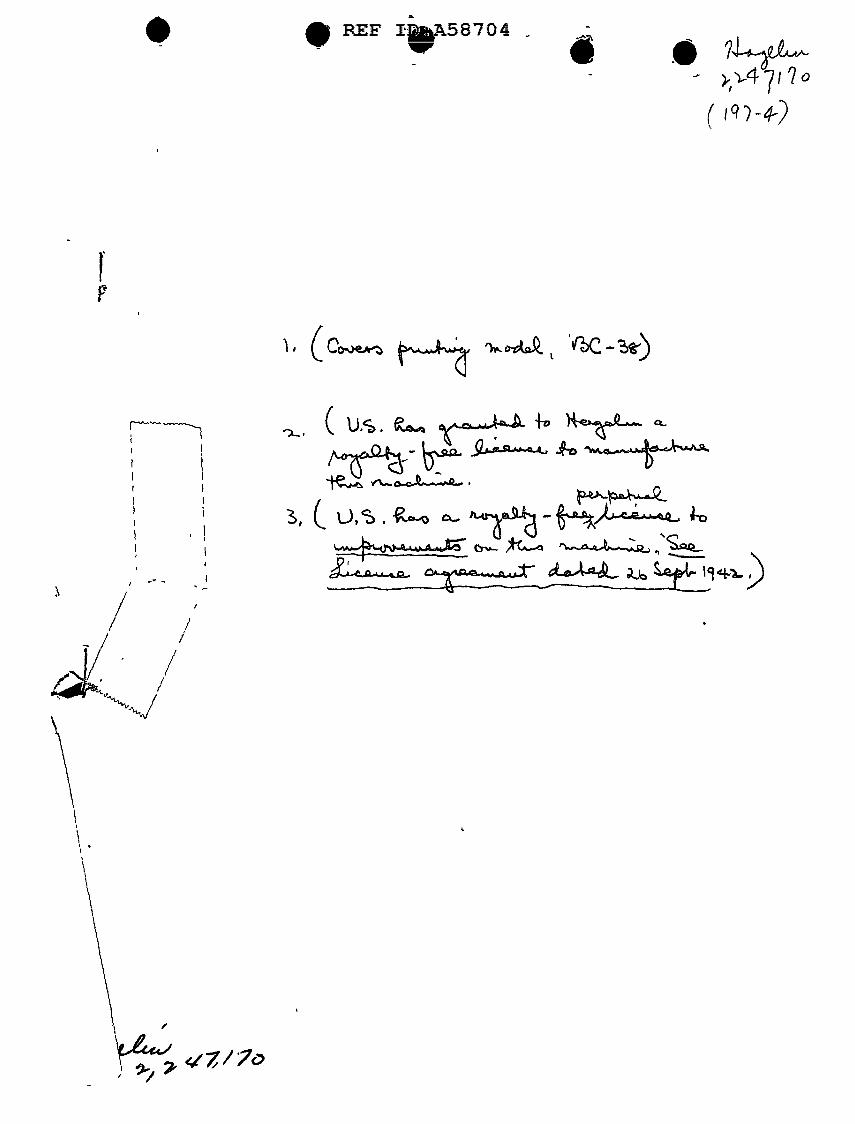
• • 74-a~ }, ),,.4 7 I ? o
( lq/-4') '.


![United States Patent - OSS.Net · United States Patent [19] Farwell 11111 111111111111 111111lllillllllll11 111111111111111 11111111111iI11111iii US005363858A [11] Patent Number:](https://static.fdocuments.in/doc/165x107/603905c969795821012ab708/united-states-patent-oss-united-states-patent-19-farwell-11111-111111111111.jpg)
