
United States Patent - NASA · United States Patent [191 ... utilizes a series combination of a...
14
United States Patent [191 Rippel et al. VOLTAGE REAPPLICATION RATE CONTROL FOR COMMUTATION OF THYRISTORS Inventors: Wally E. Rippel, Altadena; Dean B. Edwards, Monrovia, both of Calif. Assignee: California Institute of Technology, Pasadena, Calif. Appl. No.: 187,620 Filed: Sep. 15, 1980 Int. CI.3 ..................... H02M 7/515; H03K 17/73 Field of Search ................... 363/57, 58, 137, 138; U.S. Cl. ................................ 363/138; 307/252 B; 307/252 M; 363/57; 363/58 307/252 B, 252 M, 252 J 1561 References Cited U.S. PATENT DOCUMENTS 3,694,670 9/1972 Marzolf .......................... 307/252 M 3,872,364 3/1975 Hubner ................................. 363/31 3,928,775 12/1975 Steigerwald ................... 307/252 M 4,107,551 8/1978 Akamatsu ...................... 307/252 M FOREIGN PATENT DOCUMENTS 54-99933 8/1979 Japan ..................................... 363/58 OTHER PUBLICATIONS SCR Manual, Fifth Edition, G.E. Co., 1977, pp. 63-67, 133 & 139-141. German Publication “Elektrische Bahnen”, 77 (1979), H. 11, by Bohm & Kruger, pp. 306-3 12. Primary Examiner-William H. Beha, Jr. Attorney, Agent, or Firm-Freilich, Hornbaker, Wasserman, Rosen & Fernandez WI ABSTRACT A circuit for commutating a thyristor (21) by shunting its current for a minimum interval, thereby removing sustaining voltage to said thyristor, then subsequently restoring voltage to said thyristor at a predetermined rate, utilizes a series combination of a commutation electronic switch (22) and an isolated dc voltage supply (23) connected in parallel with the thyristor. The volt- age supply is arranged with a polarity that permits the current flowing through the thyristor in one direction to be bypassed through the series combination while the commutation switch is turned on and to reverse bias the thyristor when the commutation switch is fully on. A dv/dt control circuit (24) limits the rate of rise of volt- age across the commutation switch (22) as it is turned off in response to a command input signal. The dv/dt control circuit is comprised of a constant current drive (31) and a capacitor (32) connected between the output terminal of the commutation switch and the control input terminal of the commutation switch. The thyristor may be a triac (40) with two commutation switches (42, 43), one for current of each polarity, or with a single commutation switch (55) and a bridge circuit (52-55) for selecting the polarity of the switch (56). 16 Claims, 13 Drawing Figures COMMAN INPUT https://ntrs.nasa.gov/search.jsp?R=20080004227 2018-07-12T07:48:42+00:00Z
Transcript of United States Patent - NASA · United States Patent [191 ... utilizes a series combination of a...

United States Patent [191
Rippel et al.
VOLTAGE REAPPLICATION RATE CONTROL FOR COMMUTATION OF THYRISTORS
Inventors: Wally E. Rippel, Altadena; Dean B. Edwards, Monrovia, both of Calif.
Assignee: California Institute of Technology, Pasadena, Calif.
Appl. No.: 187,620
Filed: Sep. 15, 1980
Int. C I . 3 ..................... H02M 7/515; H03K 17/73
Field of Search ................... 363/57, 58, 137, 138;
U.S. Cl. ................................ 363/138; 307/252 B; 307/252 M; 363/57; 363/58
307/252 B, 252 M, 252 J
1561 References Cited U.S. PATENT DOCUMENTS
3,694,670 9/1972 Marzolf .......................... 307/252 M 3,872,364 3/1975 Hubner ................................. 363/31 3,928,775 12/1975 Steigerwald ................... 307/252 M 4,107,551 8/1978 Akamatsu ...................... 307/252 M
FOREIGN PATENT DOCUMENTS 54-99933 8/1979 Japan ..................................... 363/58
OTHER PUBLICATIONS
SCR Manual, Fifth Edition, G.E. Co., 1977, pp. 63-67, 133 & 139-141.
German Publication “Elektrische Bahnen”, 77 (1979), H. 11, by Bohm & Kruger, pp. 306-3 12.
Primary Examiner-William H. Beha, Jr. Attorney, Agent, or Firm-Freilich, Hornbaker, Wasserman, Rosen & Fernandez
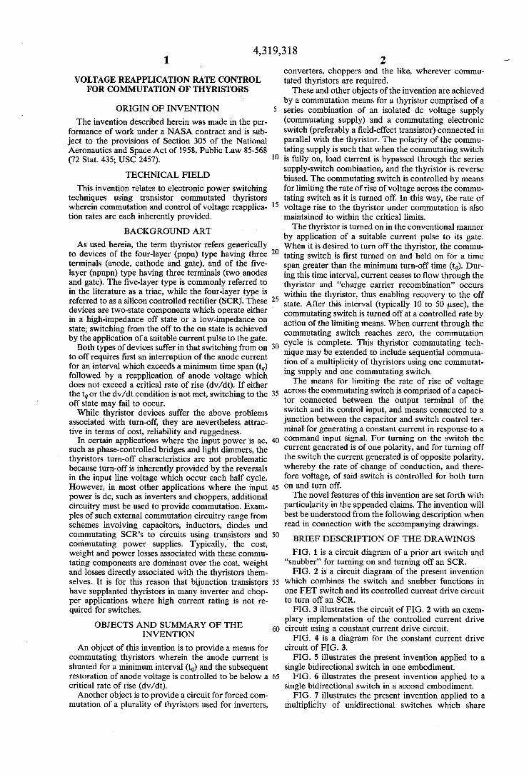
WI ABSTRACT A circuit for commutating a thyristor (21) by shunting its current for a minimum interval, thereby removing sustaining voltage to said thyristor, then subsequently restoring voltage to said thyristor at a predetermined rate, utilizes a series combination of a commutation electronic switch (22) and an isolated dc voltage supply (23) connected in parallel with the thyristor. The volt- age supply is arranged with a polarity that permits the current flowing through the thyristor in one direction to be bypassed through the series combination while the commutation switch is turned on and to reverse bias the thyristor when the commutation switch is fully on. A dv/dt control circuit (24) limits the rate of rise of volt- age across the commutation switch (22) as it is turned off in response to a command input signal. The dv/dt control circuit is comprised of a constant current drive (31) and a capacitor (32) connected between the output terminal of the commutation switch and the control input terminal of the commutation switch. The thyristor may be a triac (40) with two commutation switches (42, 43), one for current of each polarity, or with a single commutation switch (55) and a bridge circuit (52-55) for selecting the polarity of the switch (56).
16 Claims, 13 Drawing Figures
COMMAN INPUT
https://ntrs.nasa.gov/search.jsp?R=20080004227 2018-07-12T07:48:42+00:00Z

U.S. Patent MW. 9,1982 Sheet 1 of 7 4,3 19,3 18
A -I- COMM. -
6 2 1 COMMAND INPUT
B 25
FIG. 2

U.S. Patent ~ a . 9,1982 Sheet 2 of 7 4,3 19,3 18
F I G . 3
p+vcc
F I G . 4

U.S. Patent ~ a . 9,1982 Sheet 3 of 7 4,3 19,3 18
I45 \ D2 - COMM. + J A
PS.
FIG. 5
FIG. 6

U.S. Patent MU. 9, 1982 Sheet 4 of 7
YX
4,319,318
S N B L
0 0 Y I Y2 \
FIG. 7
SIA 4 ) 1\1
i S2A
AAO ::
SNA
/ BN
k
FIG. 8

U.S. Patent MU. 9,1982 Sheet 5 of 7
FIG. 9
4,3 1543 18
b Y2
-3
FIG. IO TNB
TIA
f B'
Y i I
X
z --• 2 T2A
f B2
Y2 (
YN
z TNA
BN
f N

U.S.
F
Patent MN. 9, 1982 Sheet 6 of 7 4,3 1543 18

U.S. Patent MU. 9, 1982 Sheet 7 of 7
U m 5 7
I : I : I
4,3 19,3 18
4,3 19,3 f 8 2
converters, choppers and the like, wherever commu- tated thyristors are required.
These and other objects of the invention are achieved by a commutation means for a thyristor comprised of a series combination of an isolated dc voltage supply (Commutating supply) and a commutating electronic switch (preferably a field-effect transistor) connected in parallel with the thyristor. The polarity of the commu- tating supply is such that when the commutating switch is fully on, load current is bypassed through the series supply-switch combination, and the thyristor is reverse biased. The commutating switch is controlled by means for limiting the rate of rise of voltage across the commu- tating switch as it is turned off. In this way, the rate of voltage rise to the thyristor under commutation is also maintained to within the critical limits.
The thyristor is turned on in the conventional manner by application of a suitable current pulse to its gate. When it is desired to turn off the thyristor, the commu- tating switch is first turned on and held on for a time span greater than the minimum turn-off time (tq). Dur- ing this time interval, current ceases to flow through the thyristor and “charge carrier recombination” occurs within the thyristor, thus enabling recovery to the off state. After this interval (typically 10 to 50 psec), the commutating switch is turned off at a controlled rate by action of the limiting means. When current through the commutating switch reaches zero, the commutation cycle is complete. This thyristor commutating tech- nique may be extended to include sequential commuta- tion of a multiplicity of thyristors using one commutat- ing supply and one commutating switch.
The means for limiting the rate of rise of voltage across the commutating switch is comprised of a capaci- tor connected between the output terminal of the switch and its control input, and means connected to a junction between the capacitor and switch control ter- minal for generating a constant current in response to a command input signal. For turning on the switch the current generated is of one polarity, and for turning off the switch the current generated is of opposite polarity, whereby the rate of change of conduction, and there- fore voltage, of said switch is controlled for both turn on and turn off.
The novel features of this invention are set forth with particularity in the appended claims. The invention will best be understood from the following description when read in connection with the accompanying drawings.
BRIEF DESCRIPTION O F THE DRAWINGS FIG. 1 is a circuit diagram of a prior art switch and
“snubber” for turning on and turning off an SCR. FIG. 2 is a circuit diagram of the present invention
which combines the switch and snubber functions in one FET switch and its controlled current drive circuit to turn off an SCR.
FIG. 3 illustrates the circuit of FIG. 2 with an exem- plary implementation of the controlled current drive circuit using a constant current drive circuit.
FIG. 4 is a diagram for the constant current drive circuit of FIG. 3.
FIG. § illustrates the present invention applied to a single bidirectional switch in one embodiment.
FIG. 6 illustrates the present invention applied to a single bidirectional switch in a second embodiment.
FIG. 7 illustrates the present invention applied to a multiplicity of unidirectional switches which share
1
VOLTAGE REAPPLICATION RATE CONTROL FOR COMMUTATION OF THYRISTORS
ORIGIN O F INVENTION The invention described herein was made in the per-
formance of work under a NASA contract and is sub- ject to the provisions of Section 305 of the National Aeronautics and Space Act of 1958, Public Law 85-568 (72 Stat. 435; USC 2457).
TECHNICAL FIELD This invention relates to electronic power switching
techniques using transistor commutated thyristors wherein commutation and control of voltage reapplica- tion rates are each inherently provided.
BACKGROUND ART As used herein, the term thyristor refers generically
to devices of the four-layer (pnpn) type having three terminals (anode, cathode and gate), and of the five- layer (npnpn) type having three terminals (two anodes and gate). The five-layer type is commonly referred to in the literature as a triac, while the four-layer type is referred to as a silicon controlled rectifier (SCR). These devices are two-state components which operate either in a high-impedance off state or a low-impedance on state; switching from the off to the on state is achieved by the application of a suitable current pulse to the gate.
Both types of devices suffer in that switching from on to off requires first an interruption of the anode current for an interval which exceeds a minimum time span (tq) followed by a reapplication of anode voltage which does not exceed a critical rate of rise (dv/dt). If either the tqor the dv/dt condition is not met, switching to the off state may fail to occur.
While thyristor devices suffer the above problems associated with turn-off, they are nevertheless attrac- tive in terms of cost, reliability and ruggedness.
In certain applications where the input power is ac, such as phase-controlled bridges and light dimmers, the thyristors turn-off characteristics are not problematic because turn-off is inherently provided by the reversals in the input line voltage which occur each half cycle. However, in most other applications where the input power is dc, such as inverters and choppers, additional circuitry must be used to provide commutation. Exam- ples of such external commutation circuitry range from schemes involving capacitors, inductors, diodes and commutating SCRs to circuits using transistors and commutating power supplies. Typically, the cost, weight and power losses associated with these commu- tating components are dominant over the cost, weight and losses directly associated with the thyristors them- selves. It is for this reason that bijunction transistors have supplanted thyristors in many inverter and chop- per applications where high current rating is not re- quired for switches.
OBJECTS AND SUMMARY O F THE INVENTION
An object of this invention is to provide a means for commutating thyristors wherein the anode current is shunted for a minimum interval (tq) and the subsequent restoration of anode voltage is controlled to be below a critical rate of rise (dv/dt).
Another object is to provide a circuit for forced com- mutation of a plurality of thyristors used for inverters,
5
10
15
20
25
30
35
40
45
50
55
60
65
”I

4.3 19,3 18 3
common nodes useful for such exemplary applications as poiyphase buck, boost and flyback switching regula- tors as well as half-wave and full-wave polyphase in- verters.
FIG. 8 illustrates an application of the circuit of FIG. ’7 to polyphase switching regulators; when node AA is common to input and output, boost mode operation results; when node BB is common, flyback mode opera- tion results; and when node CC is common, buck mode operation results.
FIG. 9 illustrates an application of the present inven- tion to a multiplicity of bidirectional switches which share a common node.
FIG. 10 is a variation of the circuit of FIG. 9. The circuits of FIGS. 9 and BO apply to polyphase “ac switching regulators.”
FIG. 11 illustrates the present invention applied to a multiplicity of unidirectional switches which form a generalized switching matrix.
FIG. 12 illustrates an application of the present inven- tion to a multiplicity of bidirectional switches which form a generalized switching matrix.
FIG. 83 illustrates application to a polyphase bridge inverter various techniques for practicing the invention illustrated in FIGS. 8 and 11.
Reference will now be made in detail to preferred embodiments of the invention, exemplars of which are illustrated in the accompanying drawings.
DESCRIPTION O F PREFERRED EMBODIMENTS
To better understand the problem and its solution by this invention, a representative prior-art solution to the problem will first be described with reference to FIG. 1 which shows a silicon-controlled rectifier (SCR) 10 connected with a gate drive circuit 11 and a bijunction transistor commutation switch 12. Prior to the applica- tion of a positive current gate pulse, the SCR is assumed to be in the offstate and current flow between two nodes A and B is limited to the SCR leakage current. Upon application of a current pulse to the gate, the SCR switches to the on state and current flow from A to B is limited only by an external circuit that includes a power source.
The SCR is typically turned off by momentarily turn- ing on the bijunction transistor switch 12 which effec- tively places commutation power supply 83 in parallel with the SCR, directs load current away from the SCR, and back biases the SCR. If current is diverted through transistor 12 for an interval which exceeds the SCR turn-off time (tq), the SCR will revert to the off state when the transistor switch 82 is turned off, providing that the voltage reapplication rate (dv/dt) to the anode of the SCR does not exceed a critical limit of the SCR. In order to assure that the applied dv/dt does not ex- ceed the rated dv/dt of the particular SCR, capacitor C, must have a value greater than I,,,/(dv/dt) rating, where I,n,, is the maximum current to be commutated and dv/dt is the manufacturer’s rating of the SCR. Diode D,y directs the load current through the capacitor C,yduring turn off, and resistor R,y discharges the capaci- tor C, to near zero voltage during the on interval of the SCR. The combination C,. ID, and R, in the circuit en-
5
10
15
20
25
30
35
40
45
50
5 5
60
closed by a dotted line Piis referred ‘to as a “snubber.”
20 is provided in the usual manner to inject a current pulse into the gate of an SCR 21 to turn it on. An FET switch 22 is connected in parallel with the SCR through
Referring now to FIG. 2, an SCR gate drive circuit 65
a commutating power supply 23 which functions as an isolated voltage source. The FET is driven by a control circuit 24. In response to an “on voltage” applied to a command input 25, the control circuit drives the F E T on, but limits the rate of change in the drain-to-source voltage to a fixed value. After a given time interval, an “off voltage” may be applied to control circuit 24 which turns off the FET, but with a rate of voltage change (“slew” rate) that is less than the rated dv/dt of the SCR.
It i s thus evident that the controlled FET switch replaces both the bijunction transistor and snubber of FIG. 1. While a bijunction transistor could conceptu- ally be used in this controlled slew mode, resulting second breakdown effects would cause such devices to suffer internal destruction. By contrast, FET’s which are essentially free from second breakdown may be operated in this mode without damage. However, since further development of the technology of bijunction transistors may overcome this problem, and still other types of semiconductor switches may be developed for use in this controlled slew mode, it should be under- stood that FET switches are shown only by way of example, and not by way of limitation. The important part of the combination is the control circuit for the switch which samples the voltage at the output of the switch (Le., the drain of an FET or the collector of a bijunction transistor) and turns off the switch at a con- trolled voltage rate. It also controls the output voltage when the switch is turned on, but it is the turn-off rate that is important.
The control circuit 24 is comprised of a servo means for sensing the output voltage of the switch 22 over a line 26, and so controlling operation of the switch 22 over a line 27 as to maintain the slew rate below the rated dv/dt of the SCR, both while turning the switch 22 on and, more importantly, while turning the switch 22 off to maintain reapplication of anode voltage to the SCR below its rated dv/dt. The combination of the switch 22 and control circuit 24 thus serves the purpose of the prior art transistor switch 12 and snubber 16. It is in this sense that the controlled switch 22 is said to replace the bijunction transistor and snubber of the prior art. The present invention thus does away with the prior art snubber.
It will be noted that by using a linearly controlled switch, constant dv/dt values are dynamically achieved independent of the load current. Accordingly, under reduced load conditions, the losses associated with fi- nite dv/dt are proportionately reduced. By contrast, the prior-art (resistor-capacitor-diode) snubber produces dv/dt values which vary reciprocally with the load current and losses which are independent of the load. Although the switch and control circuit will have losses which are equivalent to losses of the snubber at full load, the losses are proportionately less at reduced cur- rent loads with this controlled slew mode of commutat- ing an SCR.
The technique applies to virtually all cases in which electric currents are switched on and off by electronic means. The following is a partial listing of such cases which will be described along with the preferred eni- bodiments of the invention as applied to the individual cases: 1. Single Unidirectional Switch
These topologies enable turn on and turn off of single branch unidirectional currents. The preferred enibodi- ment consists of a single SCR which has connected in

4.3 19,3 18 5
parallel with it a series combination of commutating supply and switch. Specific examples include buck reg- ulators, boost regulators and flyback regulators as well as simple dc switching and circuit breaker applications. 2. Single Bidirectional Switch
These topologies enable turn on and turn off of single branch bidirectional currents. Two preferred embodi- ments are included. The first consists of a single triac which is paralleled by two branches, each consisting of an isolated voltage supply, a commutating switch and a diode. The polarities of the branch components are such that one branch commutates “forward” triac currents, and the other branch commutates “reverse” triac cur- rents. In the second, a series combination consisting of one voltage supply and one commutating switch is con- nected to a “polarity reversing” SCR bridge, the output of which shunts the triac. With one pair of bridge SCRs fired on, the supply-switch combination commutates “forward” triac currents and with the complimentary pair of bridge SCRs fired on, “reverse” currents are commutated. Specific examples for both embodiments include ac switches, ac circuit breakers and ac equiva- lents of the buck, boost and flyback regulators. 3. Multiunidirectional Switches Having One Buss in
Common These topologies enable individual turn on and turn
off of multibranch unidirectional currents which flow toward (or away from) a common node. The preferred embodiment consists of N main SCRs having common anodes (or cathodes), a series combination of one volt- age supply and one commutating switch and N commu- tating SCR’s which selectively connect the supply- switch combination across one of the N main SCRs. Specific examples include multiphase regulators of the buck, boost and flyback tapes and half-wave multiphase inverters. (Two such circuits may be used for a full- wave multiphase bridge inverter.) 4. Multibidirectional Switches Having One Buss in
Common These topologies enable individual turn on and turn
off of multibranch bidirectional currents which flow toward or away from a common node. Two preferred embodiments are illustrated. The topology of the first embodiment resembles the previously described Multi- unidirectional Switch topology except that triacs re- place the main SCR’s and two complementary commu- tation circuits are used (one for “forward” and the other for “reverse” currents), each consisting of one supply, one switch and N SCRs. Specific examples include multiphase ac regulators and single-phase ac to poly- phase ac bidirectional frequency changers. 5. Multiunidirectional Switches used in Generalized
Switch Matrix These topologies enable individual turn on and turn
off of multibranch unidirectional currents which flow toward (and/or away from) a multiplicity of common nodes. The preferred embodiment consists of N main SCRs with anodes connecting to j distinct nodes and cathodes connecting to k distinct nodes (where both j and k may range between 2 and N) and j + k commutat- ing SCR’s which selectively connect the supply-switch series combinations across one of the N main SCR’s. Suecific examules include multiuhase. multichannel
6 These topologies enable individual turn on and turn
off of multibranch bidirectional currents which flow toward (and/or away from) a multiplicity of common nodes. The preferred embodiment consists of N main
5 triacs with number one anodes connecting to j distinct nodes and number two anodes connecting to k distinct nodes (where both j and k may range between 2 and N) and j + k commutating triacs which selectively connect the supply-switch and SCR bridge series combination
10 across one of the main triacs for bidirectional commuta- tion. Specific examples include the most generalized form of ac control wherein bidirectional energy flow between systems of differing numbers of phases may be controlled while allowing independent control of fre-
A preferred servo means by which the FET drive is implemented is shown in FIG. 3 enclosed by a dotted line 30. The servo means is comprised of a constant current drive circuit 31 and a capacitor 32 connected
20 between the gate and drain of FET switch 33. The FET switch is connected in series with a commutating power supply 34, and the series circuit is connected in parallel with an SCR 35. An SCR driver 36 is used to turn the SCR on in the usual way. When the SCR is to be turned
25 off, a pulsed signal is applied to the current drive circuit at a command input terminal 37. This in turn causes a constant current I1 to be delivered by the current drive circuit to the gate-capacitor node. If capacitor 32 is sufficiently large (e.g., ten times the internal FET ca-
30 pacitance), most of the drive circuit current will be delivered to the capacitor. Next, if the effective voltage gain of the FET is high compared to unity (which is essential), then the drain voltage will have a s!ew rate of fall given by -Ii/C!, where C is the capacitance of the
35 capacitor 32. The drain-to-source voltage continues falling at this rate until saturation of the FET is reached, at which time the current into capacitor 32 can no longer be maintained at I1 and the current drive circuit saturates, thus reaching a maximum gate voltage. The
40 FET is thus driven from off to full on at a controlled rate. The connection of the FET drain to the capacitor corresponds to the line 26 of FIG. 2 to provide feedback sensing of the drain voltage to the capacitor 32 for a controlled rate of change of gate voltage, thereby pro-
45 viding servo control of the rate at which the FET is turned on.
After a time interval of tq, the input command signal to the current drive circuit may be removed. This in turn causes the current drive circuit to output a nega-
50 tive current (-12) which, in line with the previous arguments, causes the FET to turn off with drain to source slew rate of I2/C. This slew rate continues until the drain current essentially reaches zero, at which time the current drive circuit saturates, thus reaching a maxi-
55 mum negative output voltage. At this point, the com- mutation cycle is complete.
One embodiment for the current drive circuit 31 is shown in FIG. 4. In the absence of a command input signal, transistors QI, 4 2 and 4 3 are off. This allows
60 transistor 44 to be held on via current through resistor R4. With transistor Q4 on, a fixed voltage is established at the junction of resistors R7 and R8 which in turn causes transistor Q6 to sink a constant current (- 12).
Transistor 0 1 (which mav be either a conventional
15 quency, power factor and voltage levels.
. , . \
regulators and multistep, multiphase half wave and full 65 bijunction transistor or part of an optical coupler) satu- wave inverters. rates in response to an input signal and thereby causes 6. Multibidirectional Switches used in Generalized the junction between resistors RB and R2 to drop,
which in turn causes transistor 42 to saturate. Current Switch Matrix

4.3 19,3 1 8 7
through resistor R3 turns resistor Q3 on to saturation and transistor Q4 off. With transistor Q3 on, transistor Q5 is caused to source a constant current (11). Capaci- tors CB and 632 are for added noise immunity while resistors R2, R5 and R8 bypass leakage currents.
FIG. 5 illustrates an application of the basic invention described with reference to FIGS. 2 and 3 to the com- mutation of a triac 80 wherein bidirectional currents may be turned on and off between nodes A and B. The triac is turned on in the conventional way using a cur- rent pulse generated by a driver 41 and applied to the triac gate.
Since a triac is equivalent to two SCR’s connected in antiparallel with a common gate electrode, it can pro- vide switching action for current between nodes A and B of either polarity in response to a current pulse ap- plied to its single gate electrode. The polarity of the current will depend only upon the polarity of the volt- age applied to nodes A and B.
For commutation of forward currents (A to B), an appropriate drive signal is applied to an FET switch 42 and for reverse currents (B to A), an appropriate drive signai is applied to an FET switch 43. Diodes DB and 0 2 assure that commutating currents through the FET switches 42 and 43, and their respective commutating power supplies 44 and 45, are of the proper polarity, and that only one FET switch conducts. In this circuit dia- gram, and subsequent circuit diagrams, the FET gate drive circuit is not shown for simplicity; in each case, the gate drive circuit described with reference io FIGS. 2, 3 and 4 is applicable.
FIG. 6 illustrates a variation of the bidirectional cir- cuit shown in FIG. 5. Again a triac 50 is turned on by a current pulse applied to its single gate electrode by a drive circuit 51. For commutation of forward currents (A to B) through the triac, SCRs 52 and 54 are turned on in conjunction with an FET switch 56 in series with a commutating power supply 57. For reverse current cornmutation, SCRs 53 and 55 are turned on in conjunc- tion with the FET switch 56.
FIG. 7 illustrates an application of the basic circuits of FIGS. 2 and 3 to the commutation a multiplicity of SCR’s S1A through SNA having common anodes (or cathodes) at a node A using commutation SCR switches SIB through SNB connected to respective nodes Bk through BN. When commutation of a particular main SCR switch SiA is desired, the corresponding commu- tation SCR switch SiB is turned on, and a drive signal is applied to an FET switch 60. The result is controlled switching of unidirectional current from an input termi- nal X to selected outputs terminals Y9, Y2 . , . YN.
FIG. 8 illustrates an application of the circuit to a conventional polyphase switching regulator, where inductors LB through LN are the inductances, D1 through DN are the commutating (freewheeling) di- odes, and SCR switches SBA through SNA are the
5
10
15
20
2 5
30
35
40
4s
8 rents, such as A to BE, an SCR FE from one group FF is fired and an appropriate drive signal is applied to FET switch 70. For commutation of reverse currents, such as BB to A, an SCR RB from another group RR is fired and an appropriate drive signal is applied to FET switch 72.
FIG. 10 is a variation of the circuit of FIG. 9 employ- ing the basic circuit of FIG. 6 with a second group of triacs TPB through TNB, but instead of two commuta- tion switches, only one FET switch DO is used with four SCR switches SI-%. Forward currents such as A to R1 are commutated by firing SCR’s SI and S4, and triac TBB, while applying the appropriate drive to FET switch 80. Reverse currents are commutated by firing SCR’s S2 and S3, and the appropriate tric, while driving FET switch 80.
FIG. 11 illustrates an application of the basic circuit of FIGS. 2 and 3 to the commutation of a multiplicity of SCR’s SIP through SIvIN connected in a generalized switching matrix with switches SAB-SAM and SBB- SBN coupling an FET switch 90 and power supply 91 between selected input and output terminals AI-AM and B%-BW. In that manner, a total of M x N main SCR’s provide all possible current paths between M input terminals and N output terminals. To commutate the SCR which connects between the input terminal Ai and the output terminal BJ, SCRs SAi and SBJ are fired and an appropriate drive signal is applied to FET switch 90.
FIG. 12 illustrates an application of the basic circuit of FIGS. 2 and 3 to the commutation ofa multiplicity of triacs connected in a generalized switching matrix. In the general case, a total of M X N main triacs provide all possible bidirectional current paths between M termi- nals AI-AM and N terminals BB-BN. In order to coni- mutate “forward” current, the triac which connects between the itll input and the j r l l output terminal, triacs TAi and TBj and SCR’s SI and SIB are fired and an appropriate signal is applied to an FET switch 92. Re- verse currents are commutated similarly except that SCR’s SI and S3 are fired in place of SI and S4.
FIG. 13 illustrates the manner in which the various techniques described with reference to FIGS. 2 through 12 may be utilized in a particular application. The illus- trative example chosen is a polyphase bridge inverter utilizing SCR switches as described with reference to FIGS. 3 and 7 in a switching matrix as described with reference to FIG. BE. Triac switches as described with reference to FIGS. .§, 6, 9, PO and I3 could be similarly
50 combined in a particular application to take advantage of the bidirectional current capability of the triacs.
Referring now to FIG. 13, it may be readily apprcci- ated that a specialized switching matrix is provided to alternately connect positive and negative terminals of a
5 5 dc power source 100 to a plurality of output terminals 1 through N in a Dhase relationship controlled by the -
N-phase chopper switches. When commutation of a particular chopper switch SiA is desired, the corre- sponding commutation switch SIB is fired, and a drive signal is applied to FET switch 60. Depending on 60 whether terminal AA, BB or CC is common to both input and output, the circuit may function as a boost, buck-boost or buck chopper.
FIG. 9 illustrates an application of the basic circuit of FIGS. 2 and 3 to the commutation of a multiplicity of 6 5 triacs TI through T N having a common node A at one of their terminals and separate nodes BB through BN at their other terminal. For commutation of forward cur-
timesyhat SCR switches are turndd on and off in one main group of SCRs IA through I N and another main group of SCRs BB through NB by control signals P+l through P+N and NI$H through N+N generated in a control circuit not shown. Each group of SCRs is used in a switching matrix similar to that shown in FIG. 8, except that inductors LPA-LNA and LIB-LNB associ- ated with switches 1A-PN and IB-NB are not con- nected to a common terminal. Instead the correspond- ing inductors of the two main groups of SCR switches are connected together at terminals B through N. Con- sidered from a different point of view, the circuit of

4,3 19,3 18 9 10
FIG. 13 is like the switching matrix of FIG. 11 where, plicity of main current carrying thyristors (such as in for each main group of switching SCRs, there is one the inverter of FIG. 13) it is also important to control input terminal (positive or negative terminal of the the rate at which a commutation electronic switch is power supply) and a plurality of output terminals (1-N) turned on. Otherwise, the rate of change of voltage corresponding to, for example, an input terminal A1 and 5 across the commutation switch being turned on may output terminals B1-BN in FIG. 11. exceed the dv/dt capability of one or more of the thy-
In order that a single commutation switch 101 and ristors in the circuit. While specific examples have been power supply 102 be time shared for commutating the given, it is recognized that modifications and variations two main groups of SCRs, two additional steering SCR may readily occur to those skilled in the art. Conse- switches SA and SB are provided with the steering 10 quently it is intended that the claims be interpreted to SCR switches IC-NC and 1D-ND to be used with the cover such modifications and variations. respective SCR switches of the main groups BA-NA What is claimed is: and 1B-NB. Although two circuits like that of FIG. 8 1. A circuit for commutating a thyristor by shunting are combined with steering switches SA and SB for its current for a minimum interval, thereby removing time sharing a single commutating switch and power 15 sustaining current to said thyristor, then subsequently supply, it would, of course, be possible to utilize a sepa- restoring voltage to said thyristor at a predetermined rate commutating switch and power supply for each rate, comprising main group of SCR switches. a series combination of a commutation electronic
In operation, a select SCR is turned on to connect a switch and an isolated dc voltage supply connected positive or negative terminal of the dc power supply to 20 in parallel with said thyristor, said commutation a particular terminal 1 through N, such as SCR switch switch having a control input terminal, and said la. Current then flows through inductance LPB. To isolated dc voltage supply being arranged with a commutate the SCR switch lA, steering switches SA polarity that permits thyristor current flowing in and 1C are turned on as well as the commutation switch one direction to be bypassed through said series 101 to shunt current from the switch 1A. Similarly, to 25 combination while said commutation switch is commutate the SCR switch 1B, the steering switches turned on in response to a command input signal, 1D and SB are turned on with the commutation switch and permits reverse biasing said thyristor when 101 to shunt current from the switch 1B. Steering cir- said commutation electronic switch is fully on, and cuits SA and SB thus determine whether a positive or servo means for limiting the rate of rise of voltage negative terminal SCR is to be commutated, and the 30 across said commutation switch as said switch is groups of steering circuits 1C-NC and 1D-ND deter- turned off in response to said command input signal mine which one. applied to said servo means, said servo means being
In order to handle regenerative and reactive currents, connected to receive said command input signal, the main SCRs 1A-NA and 1B-NB are paralleled by and connected to a sensing point on said series respective diodes DIA-DNA and D2B-DNB. To 35 combination for sensing voltage across said com- allow reverse biasing of the SCRs during commutation, mutation switch. and to prevent excessive commutation currents from 2. A circuit as defined in claim 1 wherein said servo flowing through the antiparallel diodes, inductors limiting means is comprised of circuit means for gener- L1A-LNA ad LIB-LNB are connected as shown. ating a constant current to said control input terminal of These inductors, which are preferably of the saturating 40 said commutation switch in response to said command type, have the added advantage of reducing di/dt dur- input signal, and a capacitor connected between said ing SCR turn on. control input terminal of said commutation switch and
The circuit of FIG. 13 may be operated in a moduiat- said voltage sensing point, whereby the rate of change ing mode where the phase to phase half cycle average of voltage across said commutation switch is controlled voltage is reduced below the input supply voltage by 45 by the rate of change of the charge in said capacitor. chopping action. Furthermore, the specific on and off 3. A circuit as defined in claim 2 wherein said con- times associated with this chopping may be selected stant current generating means produces current of one such that system or component harmonic losses are polarity to turn on said commutation switch, and of minimized. Phase rotation, frequency, and phase are opposite polarity to turn off said commutation switch, also variables which may be controlled. In addition to 50 whereby the rate of change of voltage of said commuta- the above features, the circuit, when compared with the tion switch is controlled for both turning on and turning state of the prior art, allows for reducing weight and off said commutation switch. cost, and for improved efficiency. Because of these 4. A circuit as defined in claim 1, 2 or 3 wherein said features, the circuit is ideally suited for polyphase ac electronic commutation switch is comprised of a field motors. 55 effect transistor.
It is thus evident that in many different applications, 5. A circuit as defined in claim 4 wherein said thy- wherein one or more thyristors are to be commutated ristor is selected to be a silicon controlled rectifier. by shunting its anode current with a controlled slew 6. A circuit as defined in claim 4 wherein said thy- rate, a series combination of a commutation electronic ristor is selected to be a triac. switch and an isolated dc voltage supply may be ar- 60 7. A circuit as defined in claim 6 for bidirectional ranged to shunt the anode current with a controlled current flow through said triac comprising a second slew rate in response to a command input signal, where series combination of a commutation electronic switch the slew rate is controlled by servo means connected and an isolated dc voltage supply connected in parallel between a control terminal of the switch and a point on with said triac, said second commutation switch having the series combinatioy selected for sensing voltage 65 a control input terminal, and both said second voltage across the switch. Whereas the slew rate in turning a supply and second commutation electronic switch commutation electronic switch off is important in virtu- being arranged with a polarity that permits current ally all applications, in some applications using a multi- through said triac in a direction opposite said one direc-

n n tion to be bypassed through said second series combina- tion, and permits reverse biasing said triac against con- duction in the opposite direction, when said second commutation switch is caused to turn on in response to a command input signal, and second servo means for limiting the rate of rise of voltage across said second commutation switch as it is turned off in response to a command input signal applied to said second servo means, said second servo means being connected to receive said command input signal, and connected to a sensing point on said second series combination for sensing voltage across said second commutation switch.
8. A circuit as defined in claim 6 for bidirectional current flow through said triac, and switching means selectively coupling said series combination of said commutation electronic switch and said isolated dc voltage supply for bypass current of one direction when said triac is conducting in said one direction, and for bypassing current of opposite directions when said triac is conducting in said opposite direction.
9. A circuit as defined in claim 8 wherein said switch- ing means is comprised of four switches in the form of a four sided bridge circuit having said series combina- tion connected between two opposite nodes and said triac connected between the remaining two nodes, switches on two opposite sides arranged for conduction in one direction through said series combination, with one conducting switch at each end, and the other two switches arranged for conduction in opposite directions through said series combination, with one conducting switch at each end.
10. A circuit as defined in claim 9 wherein each of said four bridge switches is comprised of a thyristor.
11. A thyristor ccnnected in series with a load and a source of electrical power to be applied through said load when said thyristor is switched on, means for switching said thyristor on, and commutation means connected in parallel with said thyristor for switching said thyristor off, said commutation means comprising a transistor and an isolated source of dc voltage con- nected in a series circuit, said series circuit being con-
4,319,318
45
12 nected in parallel with said thyristor, said transistor having a control input terminal and an output terminal and said isolated dc voltage source being arranged with a polarity that permits thyristor current flowing in one
5 direction to be bypassed through said transistor while said transistor is turned on, and at the same time permits reverse biasing said thyristor while said transistor is turned on, a bipolar source of constant current con- nected to said control input terminal of said transistor,
lo said current source providing current of one polarity to turn said transistor on and of opposite polarity to turn said transistor off in response to a command input sig- nal, and a capacitor connected between said transistor control input terminal and said transistor output termi-
l 5 nal to control the rate of change of voltage across said transistor as it is turned on and as it is turned off.
12. A combination as defined in claim 11 wherein said thyristor is unidirectional.
13. A combination as defined in claim 11 wherein said thyristor is bidirectional, and including a second com- mutation means in parallel with the transistor and iso- lated source of dc voltage polarized for commutation of said thyristor while conducting in the opposite direc-
14. A combination as defined in claim 11 wherein said thyristor is bidirectional, and including a plurality of switches in a circuit for selectively changing the polar- ity of said commutation means.
15. A combination as defined in claim 111, 12, 13 or 14 in which said commutation transistor is comprised of a field-effect transistor.
16. A combination as defined in claim 15 wherein said field-effect transistor has internal capacitance and said
35 capacitor is selected to have a value of capacitance so large relative to said internal capacitance of said field- effect transistor that the particular value of internal capacitance will not materially affect the rate of change of voltage across said field-effect transistor in turning
2o
25 tion.
30
40 on and off. * * * * *
50
55
60
65

![US006048508A United States Patent [19] [11] Patent Number](https://static.fdocuments.in/doc/165x107/620734fe49d709492c2f0184/us006048508a-united-states-patent-19-11-patent-number.jpg)


![United States Patent [19] [11] Patent Number: 5,958,384 hair regrowth patent.pdfUnited States Patent [19] [11] Patent Number: 5,958,384 Holick ... anti-elastase activity demonstrated](https://static.fdocuments.in/doc/165x107/5b09dd3e7f8b9a604c8b8728/united-states-patent-19-11-patent-number-5958-hair-regrowth-patentpdfunited.jpg)


