
UNITED STATES MARINE CORPS · Web viewUNITED STATES MARINE CORPS ENGINEER EQUIPMENT WARRANT...
105
UNITED STATES MARINE CORPS ENGINEER EQUIPMENT WARRANT OFFICER/CHIEF’S COURSE ENGINEER EQUIPMENT INSTRUCTION COMPANY MARINE CORPS DETACHMENT 686 MINNESOTA AVENUE FORT LEONARD WOOD, MISSOURI 65473 LESSON PLAN ENGINEER EQUIPMENT CAPABILITIES AND LICENSING PROGRAM LESSON ID: EEC/EEO-B01 ENGINEER EQUIPMENT WARRANT OFFICER/CHIEF COURSE CID: A16ACN1/A1613E1 REVISED 11/23/2011
Transcript of UNITED STATES MARINE CORPS · Web viewUNITED STATES MARINE CORPS ENGINEER EQUIPMENT WARRANT...
UNITED STATES MARINE CORPSENGINEER EQUIPMENT WARRANT OFFICER/CHIEF’S COURSE
ENGINEER EQUIPMENT INSTRUCTION COMPANYMARINE CORPS DETACHMENT686 MINNESOTA AVENUE
FORT LEONARD WOOD, MISSOURI 65473
LESSON PLANENGINEER EQUIPMENT CAPABILITIES AND LICENSING PROGRAM
LESSON ID: EEC/EEO-B01
ENGINEER EQUIPMENT WARRANT OFFICER/CHIEF COURSE
CID: A16ACN1/A1613E1
REVISED 11/23/2011
APPROVED BY ____________________________ DATE ________________
(ON SLIDE #1)
INTRODUCTION (10 MIN)
1. GAIN ATTENTION: As an engineer equipment officer/chief, an engineer equipment operation section will fall under your responsibilities. In order to prepare for this, you as the duty expert should know the capabilities and limitations of engineer equipment, be able to identify engineer tasks that those items of equipment are designed to perform, and be able to supervise the Tactical Engineer Equipment Licensing Program. This period of instruction will assist you in the accomplishment of your mission, to include preventive maintenance indicators, and equipment safety.__________________________________________________________________________________________________________________________________________________________________________________________________________________
2. OVERVIEW: Good morning/afternoon, my name is ________________. The purpose of this lesson is to familiarize you, the student with the characteristics, employment, inspection procedures, operational safety requirements of engineer equipment, and give you the knowledge to supervise a licensing program.
(ON SLIDE #2)
3. LEARNING OBJECTIVE(S):
a. TERMINAL LEARNING OBJECTIVE:
(1) Provided engineer equipment, available resources, a mission, and references, manage/supervise engineer equipment operations to support mission requirements per the reference. (1310-XENG-2004/1349-XENG-2004)
(2) With personnel, documentation, licensing records, and references, supervise engineer equipment licensing program ensuring equipment operators are licensed per the reference. (1310-AMIN-2009/1349-ADMIN-2009)(ON SLIDE #3)
INSTRUCTOR NOTE Have students read learning objectives to themselves.
2
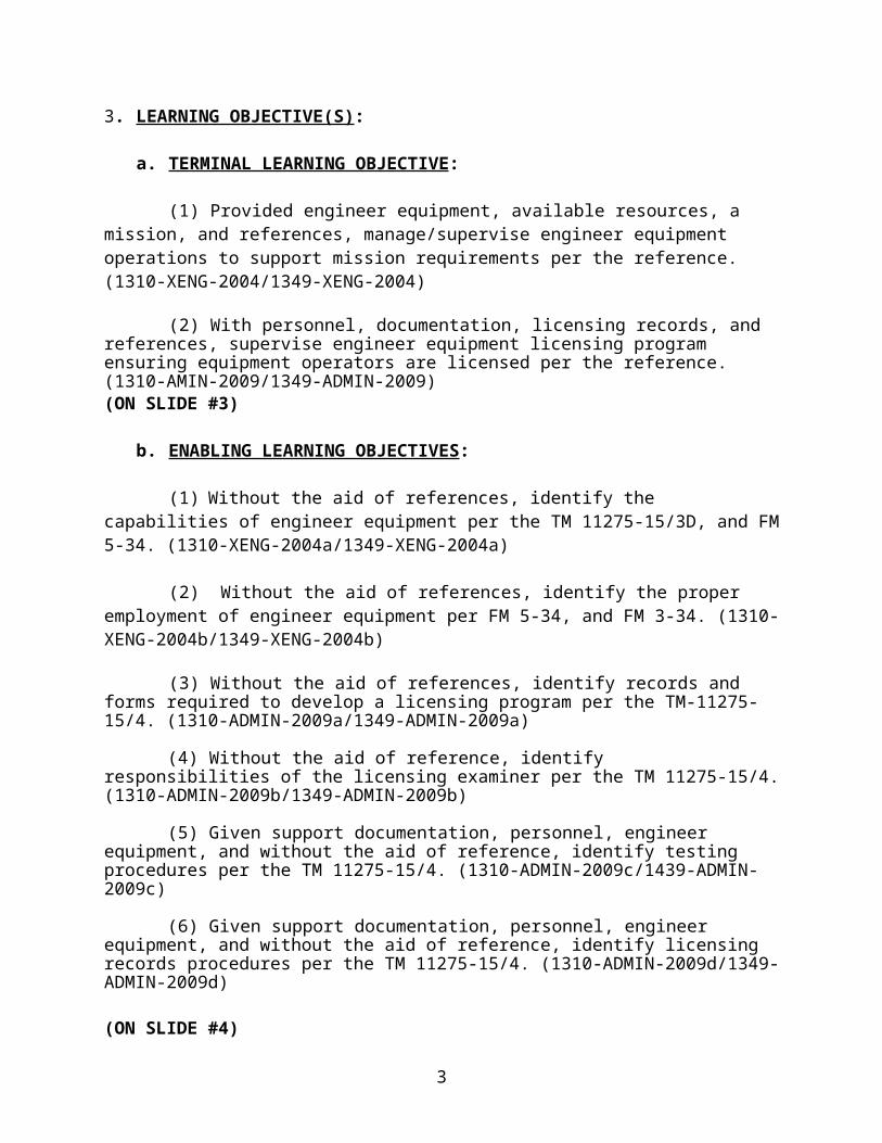
b. ENABLING LEARNING OBJECTIVES:
(1) Without the aid of references, identify the capabilities of engineer equipment per the TM 11275-15/3D, and FM 5-34. (1310-XENG-2004a/1349-XENG-2004a)
(2) Without the aid of references, identify the proper employment of engineer equipment per FM 5-34, and FM 3-34. (1310-XENG-2004b/1349-XENG-2004b)
(3) Without the aid of references, identify records and forms required to develop a licensing program per the TM-11275-15/4. (1310-ADMIN-2009a/1349-ADMIN-2009a)
(4) Without the aid of reference, identify responsibilities of the licensing examiner per the TM 11275-15/4. (1310-ADMIN-2009b/1349-ADMIN-2009b)
(5) Given support documentation, personnel, engineer equipment, and without the aid of reference, identify testing procedures per the TM 11275-15/4. (1310-ADMIN-2009c/1439-ADMIN-2009c)
(6) Given support documentation, personnel, engineer equipment, and without the aid of reference, identify licensing records procedures per the TM 11275-15/4. (1310-ADMIN-2009d/1349-ADMIN-2009d)
(ON SLIDE #4)
4. METHOD/MEDIA: This period of instruction will be taught using the lecture, demonstration and practical application methods and with aid of power point presentation.
(ON SLIDE #5)
5. EVALUATION:
You will be evaluated by a written exam at the time indicated on the training schedule.
INSTRUCTOR NOTEExplain Instructional Rating Forms to the students.Explain Safety Questionnaire to the students.
3
6. SAFETY/CEASE TRAINING (CT) BRIEF:
Brief the ORAW, fire exit, and inclement weather plan to the students.
TRANSITION: Are there any questions about what we will be cover-ing, or how you will be evaluated? Engineer equipment is catego-rized by their functional areas. The first section of engineer equipment we will cover is employment of material handling equip-ment, forklifts, and container handlers.
BODY (15 HRS, 40 MIN)
MATERIAL HANDLEING EQUIPMENT
(ON SLIDE #6)
1. TX51-19M (LCRTF) (15 MIN)
a. NOMENCLATURE
(1) The Light Capability Rough Terrain Forklift, TX51-19M (LCRTF) is a diesel engine powered, self-contained, rough terrain forklift manufactured by TEREX Lift Trucks, a division of Terex American.
(2) The Light Capability Rough Terrain Forklift, TX51-19M (LCRTF) is a full time four-wheel drive, and the front axle (limited slip differential) drives the rear axle (locked differential) thru a drive shaft.
(ON SLIDES #7,8)
(3) The Light Capability Rough Terrain Forklift, TX51-19M (LCRTF) is equipped with two pintle hooks, one permanently attached on the rear, and one removable pintle hook assembly with a maximum capacity of 8,000 lbs. The removable pintle hook is located on the left side rear fender of the forklift, when in the stowed position.
(ON SLIDE #9)
(4) It is the smallest forklift in the Marine Corps with a gross vehicle weight of 13,500 pounds.
4
b. CAPABILITIES
(1) The Light Capability Rough Terrain Forklift, TX51-19M (LCRTF) has a fully hydraulic two section-telescoping boom. The maximum lifting capacity is 5,070 pounds at a 24 inch load center; boom fully retracted.
(2) The maximum lifting height is 18 feet 9 inches. The maximum reach forward is 10 feet 9 inches, measured from the front tires.
(ON SLIDE #10)
(3) The load chart must be used to determine a safe boom angle and boom length, with respect to the weight of the load.
(4) Fording depth of 36 inches.
(5) It is equipped with, front (two-wheel), crab, or 4-wheel steering.
(6) It is also equipped with a hydraulic motor disconnect which is utilized when the forklift is disabled and is being towed.
(ON SLIDE #11)
c. EMPLOYMENT
(1) The mission of the TEREX TX51-19M is to load and unload palletized cargo from trucks, trailers, aircraft, ships and ISO containers.
(ON SLIDE #12)
d. MAINTENANCE
(1) Do not operate the starter motor for more than 20 seconds at a time. If the engine fails to start within that time, release the switch lever and wait 2 minutes before trying again. If this precaution is not followed serious damage to the starter motor may result.
5
(ON SLIDE #13)
(2) This tractor is equipped with a Load Chart. If the load chart is damaged, missing, or unreadable the forklift will be safety dead lined.
TRANSITION: We have covered the TX51-19M (LCRTF). Do you have any questions? I have questions for you. ________________________________________________________________________________________________________________________________________________________________________________________________
(ON SLIDE #14, 15)
1. QUESTIONS TO THE CLASS:
Q. Fording depth of the 5K?
A. 36 inches
Q. What is the max lifting capacity of the 5k?
A. 75,070 lbs with boom fully retracted
TRANSITION: The next item of engineer equipment we will cover is the Extended Boom Forklift EBFL.
(ON SLIDE #16)
2. EXTENDED BOOM FORKLIFT, MILITARY MILLENNIUM VEHICLE (MMV) SKYTRAK (20 MIN)
(ON SLIDE #17,18,19,20)
a. NOMENCLATURE
(1) The EBFL (MMV) is a diesel-powered, four-wheel drive, rubber tired forklift with two wheel, four wheel, and crab steering.
(2) Manufactured by OmniQuip Textron Inc.
(3) The tractor incorporates a three-section, telescoping boom.
6
(4) The MMV has a Load Moment Indicator (LMI) system which continually monitors the load on the rear axle as loads are being lifted and extended.
(5) This vehicle is equipped with a quick attach system for easy attachment changing.
(ON SLIDE #21)
b. CAPABILITIES
(1) The EBFL (MMV) is equipped with two fork attachments. The 7K carriage has a maximum lifting capacity of 7000 lbs at a 48” load center. The 11K carriage has a maximum lifting capacity of 11,000 lbs at a 24” load center.
(ON SLIDE #22)
(2) Fording depth of 30”.
(3) The maximum forward reach of the boom is 30’ from the front tires.
(ON SLIDE #23,24,25)
(4) Maximum lifting height is 42’4”
(5) The EBFL has two load charts. One for 24 inch load center (11K Carriage) and 48 inch load center (7K Carriage). Supervisors must make sure that when this tractor is operated, the load charts are strictly followed. The Load Moment Indicator (LMI) system is not intended to be an absolute replacement for the capacity charts.
(ON SLIDE #26)
c. EMPLOYMENT
(1) The extendible boom on the MMV will prove to be very helpful. It is designed to be used for loading and unloading trucks, ships, aircraft, or containers.
(2) The EBFL (MMV) in garrison can be used for loading and unloading trucks and containers and also in warehouse operations.
7
(3) In a field environment, the EBFL can be employed to load and unload palletized cargo from inside containers, as well as loading and unloading of aircraft and trucks.
(ON SLIDE #27)
d. MAINTENANCE
(1) All tractors must have an Operators Manual (TM 10794A-12/1) located inside the cab for easy access. This manual contains a General Maintenance section with a maintenance schedule and checklist with references to pertinent procedures and instructions. To prevent problems before they occur, follow the maintenance schedule.
(2) When lubricating the Carriage Fork Shaft and wear bar use ONLY Teflon Lube to coat the entire fork shaft and the wear bar. DO NOT apply GAA or any other type of petroleum base lubricant to these areas.
(ON SLIDE #28)
(3) This Tractor is equipped with a tire inflation system which will enable the tires on this vehicle to be inflated to the proper air pressure without going back to a maintenance area.
TRANSITION: We have covered the (MMV). Do you have any questions? I have questions for you. ________________________________________________________________________________________________________________________________________________________________________________________________
(ON SLIDE #29, 30)
1. QUESTIONS TO THE CLASS:
Q. What is the fording depth of the MMV?
A. 30 inches
Q. The small fork attachment will lift how much?
A. 11,000 lbs
TRANSITION: The next item of engineer equipment we will cover is the 624KR TRAM.
8
(ON SLIDE #31)
3. 624KR TRAM FORKLIFT (25 MIN)
(ON SLIDE #32)
a. NOMENCLATURE
(1) The TRAM 624KR is a diesel powered, four wheel drive, rubber tired, articulated steering tractor manufactured by John Deere.
(2) The TRAM weights 33,480 lbs, the up armored cab weights 7,000 lbs. The total weight with the armor is 40,480 lbs.
(3) The TRAM is equipped with two attachments: (Transferred from the 644E) (ON SLIDE #33)
(a) Fork attachment
a. As supervisors we must insure our operators understand the maximum lifting capacity of the equipment being operated. The maximum lifting capacity of the fork attachment of the TRAM is 10,000 lbs at a 48” load center.
(ON SLIDE #34)
(b) 4 in 1 Bucket attachment
b. The bucket is a 4-in-1 multipurpose bucket with a 2 1/2 cubic yd. capacity. The maximum lifting capacity of the TRAM, when equipped with the bucket attachment, is 7500 lbs.
(ON SLIDE #35)
(4) The TRAM can be equipped with an Up-Armor Cab, being that the old cab is removed and replaced, whole, by an armored one.
(a) The GVW is 33,480lbs. The Armored cab weights 7,000 lbs, it adjust the GVW to 40,480 once it is installed.
(ON SLIDE #36)
9
b. ADVANCE DISPLAY UNIT (ADU)
(1) The ADU is located in front of and to the right of the operator in the cab, positioned on the cab support beam.
(2) The heads-up display contains the following items:
a. hour meterb. odometerc. ambient temperature d. actual gear and travel directione. requested gearf. transmission modeg. tachometerh. speedometeri. fuel level gaugej. engine coolant temperature gaugek. hydraulic oil temperature gaugel. transmission oil temperature gaugem. engine oil pressure gaugen. ride control indicatoro. pin disconnect indicator
p. check engine indicatorq. transmission fault indicatorr. low battery voltage indicator
s. filter restriction indicatort. turn signal indicatoru. STOP indicatorv. service required indicatorw. park brake indicatorx. brake pressure indicator
(ON SLIDE #37)
c. OPERATIONAL FEATURES
(1) Return-to-Dig: A set of sensors/switches used to move the boom/bucket to predetermined positions using the hydraulic controls.
(2) Ride Control Switch: Position of the attachment (bucket/forks) in a float position to minimize the bounce of the tractor at travel speeds.
(3) Boom Height Kick-out Switch: A set of sensors/switches that stops the boom at a predetermined height.
10
(4) Return-to-Carry Switch: A set of sensors/switches that stop the boom, once it is activated and in travel in the down position, to stop in a predetermined depth.
(ON SLIDE #38,39,40,41,42)
d. EMPLOYMENT
(1) In garrison or the field environment the TRAM can be used for loading and unloading of trailers, 463L pallets, aircraft and ships.
(2) The TRAM is the most preferred piece of equipment in port operations.
(3) The bucket is primarily used as a front end loader.
(4) The bucket can also be employed as a clamshell, a dozer, and scraper.
(ON SLIDE #43,44,45,46)
d. MAINTENANCE
(1) The fork tine adjustment is very important. If the adjustment is off the fork tine cylinder will break. The adjustment is 1/8” at the top to 1/4” at the bottom.
(2) The oscillation plates need to be checked daily. If they come loose the carriage will not oscillate and cause damage to the bolts.
(3) The center pin on the fork carriage will wear down when there is a 1/8” gap, you must insert a washer and re-torque the bolt. This will keep the carriage tight.
(4) The forks cannot be dragged away from pallets. Doing so will cause fork tine damage by pulling the retaining plate away from the carriage.
(5) Retract pins should not exceed 3/8” from the carriage. If this is exceeded there is an internal problem of the sheer pin breaking or the retaining pin not coming loose. At this time the tractor must be placed in organizational maintenance for repair of retract pin cylinders.
11
TRANSITION: We have covered the 624KR. Do you have any questions? I have questions for you. ________________________________________________________________________________________________________________________________________________________________________________________________
(ON SLIDE #47, 48)
1. QUESTIONS TO THE CLASS:
Q. The TRAM bucket can lift how much?
A. 7,500 lbs.
Q. What is the weight of the up armored cab?
A. 7,000 lbs
(ON SLIDE #49)
TAKE A BREAK (10 MIN)
TRANSITION: Are there any more questions before we move on? The next item of engineer equipment we will cover is the RT 240V2 KALMAR.
(ON SLIDE #50)
4. RT 240V2 KALMAR (35 MIN)
(ON SLIDE #51)
a. NOMENCLATURE
(1) The RT 240V2 is the replacement for the current 988B RTCH.
(2) The RT 240V2 is designed to lift, move, stack or unstack 20 and 40 ft by 8 ft wide ISO containers.
(3) The RT 240V2 weighs 118,000 lbs. 128,400 lbs with the forklift kit attachment.
(ON SLIDE #52,53,54)
b.CAPABILITIES
12
(1) The RT 240V2 has a lift capacity of 53,000 lbs with the top handler and 44,000 lbs with the forklift kit. Operates on hard and/or unimproved surfaces, to include beach operations.
(2) Maximum speed is 23 mph on level ground with NO LOAD; maximum speed on level ground LOADED is 15 mph.
(3) Maximum fording depth is 60 in.
(4) Ground clearance of 18 in.
(5) Capable of being transported by truck, rail, ship, and air.
(ON SLIDE #55,56)
c.EMPLOYMENT. The RT 240V2 is used for loading, unloading, handling, and stacking containers.
(1) The concept of "break-bulk" cargo was phased out in favor of "containerized" cargo. "Break-Bulk" cargo handling is the method employed since the earliest days of shipping. Cargo was broken down into groups that can be handled by the equipment available. Although that method has worked for many years, containerization is the cargo handling method for the future.
(ON SLIDE #57)
(2) Containerization is the method by which the shipping industry is being standardized. Standardization of dimensions and weight capacities has spread across the world. Cargo containers are available in various sizes. The most common sizes are:
(a) 8' wide x 8' high x 20' long (ISO)
(b) 8' wide x 8' high x 35' long (Sealand)
(c) 8' wide x 8' high x 40' long (ISO)
(ON SLIDE #58)
(4) Every major port in this country has high-speed container equipment. This fact further enhances the idea of
13
using containers for handling military cargo. The commercial shipping industry would be immediately available to assist in the load out of military cargo in an emergency situation.
(ON SLIDE #59)
(5) Delivery of supplies for beach assaults or resupply deliveries by container versus break-bulk, offers many advantages. Supplies for a beach assault are loaded and sealed into a container in the shipping area of a logistics base.
(a) Supplies will remain intact in the container until the container lands on the beach.
(b) Damage and pilferage are virtually eliminated.
(c) Supply fouls ups are reduced.
(d) Approximately 45,000 lbs. of supplies can be delivered safe and sound in a single movement of the RT 240V2 KALMAR. The ISO container itself can weigh as much as 5,000 lbs.
(e) In addition to the protection offered by containerization a more valuable feature is the reduced time required to move the supplies inland.
(f) The RT 240V2 KALMAR provides the link between the landing craft and the beach in the supply chain of containerized cargo handling.
(ON SLIDE #60)
(6) Primarily, the RT 240V2 KALMAR is designed for employment in beach-type operations. Containers stowed aboard MPS Ships are unloaded by shipboard cranes onto various types of landing craft, and then transported to shore.
(ON SLIDE #61)
(7) The container can be loaded by the RT 240V2 KALMAR onto flatbed trailers.
(ON SLIDE #62)
(8) The RT 240V2 KALMAR may also be used in the container marshaling area. The container marshaling area is a staging area for containers. As trucks arrive loaded with containers, they
14
are quickly unloaded and staged by the RT 240V2 KALMAR. This makes the RT 240V2 KALMAR the preferred item of equipment for staging ISO containers in the marshaling area.
(ON SLIDE #63)
(9) The RT 240V2 KALMAR is capable of stacking containers three high with the gross weight of the first row being 53,000 lbs and the second row being 27,500 lbs. This allows for more space in the container marshaling area.
TRANSITION: We have covered the RT 240V2 KALMAR. Do you have any questions? I have questions for you. ________________________________________________________________________________________________________________________________________________________________________________________________
(ON SLIDE #64, 65)
1. QUESTIONS TO THE CLASS:
Q. What is the size of the standard containers used by the
USMC?
A. 8’ x 8’ x 20’
Q. Fording depth of the KALMAR RT-240?
A. 60“
Q.What is the lifting capacity of the KALMAR with the forklift kit?
A. 44,000 lbs
TRANSITION: The next item of engineer equipment we will cover is the LRT 110 7 ½ ton crane.
(ON SLIDE #66, 67)
5. LRT 110 7 1/2 TON CRANE (20 MIN)
a. NOMENCLATURE
(1) The LRT 110 is an air transportable, diesel-powered, rubber tired, four-wheel drive, four-wheel steer, 7 1/2 ton
15
capacity, hydraulically operated crane, designed to perform normal lifting operations. (ON SLIDE #68)
(2) Boom Assembly - The boom assembly consists of a two section telescopic boom with a minimum boom length of 21 3/4’ and a maximum boom length of 35 3/4’.
(3) Winch - The LRT 110 is equipped with a single drum hydraulically operated winch.
b. CAPABILITIES:
(1) The maximum lifting capacity is 15,000 lbs.
(ON SLIDE #69)
(2) The LRT 110 winch can be wrapped with a maximum 350’ of 1/2” wire rope. To ensure proper crane operations in accordance with the TM, the winch must be wrapped with at least 180’ of 1/2” wire rope.
(3) The hook block can be revved with a 3 parts of line for a maximum lift.
(4) The LRT 110 must meet load test requirements established in MCO P11262.2, prior to being employed.
(ON SLIDE #70,71,72)
c. EMPLOYMENT
(1) The 7 1/2 ton crane has two attachments, the hook block, and the working platform. Some of the uses of the hook block are:
(a) Lifting any load rigged with slings; at, above, or below ground level within the load chart limits.
(b) Installing or removing rotor blades on helicopters and engine maintenance on fixed winged aircraft.
(c) Operator efficiency is a must with wing units.
(2) The work platform is used to lift personnel and hold them in place while they perform work as high as 30’ to 35’.
16
(a) Combat engineers can use it to support vertical construction. (ON SLIDE #73)
d. MAINTENANCE
(1) The level bubble in the operators cab will vibrate out of calibration, so it must be checked periodically with a carpenter’s level.
(2) The gap between the hook shoulder and the trunnion should be 3mm.
(3) The brake reservoir caps can become unserviceable due to their position in the cab from direct sunlight.
TRANSITION: We have covered the LRT 110. Do you have any questions? I have questions for you. ________________________________________________________________________________________________________________________________________________________________________________________________
(ON SLIDE #74, 75)
1. QUESTIONS TO THE CLASS:
Q. The maximum boom length on the LRT 110?
A. 35 ¾ feet
Q. What are the two attachments for the LRT 110?
A. Hook block and work platform
TRANSITION: The next item of engineer equipment we will cover is the MAC-50.
(ON SLIDE #76,77,78)
6. MAC 50 CRANE (40 MIN)
a. NOMENCLATURE
(1) The MAC 50 is a 50 ton (100,000 lbs) capacity all-ter-rain crane utilizing bridal slings. The Marine Corps began field
17
testing these crane in January, 2007. The MAC 50 is a replace-ment for the HSHMC 25 ton crane. The lifting capacity of the crane was more than doubled by advanced engineering, but kept the same embarkation specifications to meet the standards of the Ma-rine Corps.
(2) The MAC 50 is powered by an in-line 6 cylinder, tur-bocharged Cummins diesel engine that outputs 333 HP @ 2,000 RPM and 305 HP @ 2,200 RPM. The engine has the capability of being started at temperatures as low as -25 degrees F (-32 degrees C).
(ON SLIDE #79,80,81)
b. CAPABILITIES
(1) The transmission is fully automatic or manually con-trolled by the selector buttons on the transmission panel. The transmission range has 6 forward gears and 1 reverse with a maxi-mum road speed of 48 MPH.
(2) The axles can oscillate (+ 5 in.) and can traverse a straight uphill or downhill grade of 45%. Side slope that is perpendicular to the direction of travel is reduced to only 20%.
(3) The MAC 50’s fording depth is 60 in.
(4) The boom of the MAC 50 can extend to a maximum length of 82’ 3” and a minimum fully retracted length of 27’ 8”. The boom is comprised of three sections and will telescope out section #1 fully before sections #2 & #3 deploy simultaneously (if not deployed in this order, unit maintenance should be advised).
(ON SLIDE #82)
(5) The MAC 50 is capable of operating on four outriggers that must be locked in the mid position or the full position. There are two separate load charts; one for each position.
(ON SLIDE #83)
(6) The wire rope from the boom head to the hook block is configured by “parts of line”. The permissible line pull for one length of wire rope is 9,700 lbs. When wrapped through sheaves on the hook block to the boom head, the lifting capacity increases by 9,700 lbs for each wrap or “part of line” that runs between both to a maximum lifting capacity of 100,000 lbs without slings.
18
(ON SLIDE #84)
c. EMPLOYMENT
(1) Once the crane is positioned correctly on site, the first step in setting up the crane is to prepare the outriggers and outrigger pads. The outrigger pads are to be stored in their respective travel positions until crane operations begin. If outrigger pads are not stowed properly for traveling, the tires can be punctured by them.
(ON SLIDE #85)
(2) Hook Block: The uses for the hook block are almost unlimited. A hook block may be used at, above, or below the ground level. The hook block weighs 800 pounds. Some of the uses for the hook block are:
(a) Construction and employment of bridges
(b) Installing or removing rotor blades on heli-copters and propellers on airplanes
(c) Loading and unloading ships or trucks
(d) Lifting any load rigged with slings or any vehicle equipped with lifting eyes
(ON SLIDE #86,87)
(3) Clamshell bucket: The clamshell is a vertically oper-ated attachment capable of digging loose to medium type soils at, or above ground level with a capacity of 264 gallons (6,600 lbs.). The clamshell attaches to the hook block and should be used with two parts of line. Some uses for the clamshell are:
(a) Digging foundations, footings, trenches and cellars
(b) Handling bulk material such as gravel, garbage, snow
(c) Loading of bulk material into vehicles
(d) Filling bins, such as barriers and bastions
19
TRANSITION: We have covered the MAC 50. Do you have any questions? I have questions for you. ________________________________________________________________________________________________________________________________________________________________________________________________
(ON SLIDE #88)
1. QUESTIONS TO THE CLASS:
Q. What are the two attachments for the MAC 50 crane?
A. hook block, and clamshell
Q. What is the max lifting capacity of the MAC 50?
A. 50 ton or 100,000lbs
(ON SLIDE #89)
TAKE A BREAK (10 MIN)
TRANSITION: Are there any more questions? The next item of engineer equipment we will cover is the MTL.
(ON SLIDE #90)
7. MULTI TERRAIN LOADER (MTL) (20 MIN)(ON SLIDE #91)
a. NOMENCLATURE
(1) The 277C MTL is a full-tracked, diesel engine driven, hydraulically operated, multi-terrain loader with a roll over/falling object protective structure manufactured by Caterpillar. This piece of equipment is a stand-alone TAMCN, but the bravo model (277B) is a component of the Airfield Damage Repair (ADR) kit.
(ON SLIDE #92)
b. CAPABILITIES
(1) It has superior traction, flotation and stability with minimal pressure on the ground (3.1 psi).
(2) The only differences between the two tractors are;
20
(a) Operational weight B – 9,411 lbsC – 9,389 lbs
(b) Travel SpeedB – 7 mphC – 9.3 mph
(ON SLIDE #93)
(3) The MTL has a Work Tool Carrier equipped with multiple tools. It is comprised of two sections one being 51” and the smaller one being 42”. They are stackable and are transportable on a MTVR.
(ON SLIDE #94)
c. EMPLOYMENT
(1) It is used for earth moving as well as general construction.
(2) Some of the tools that can be utilized are:
(a) Angle blade(b) Auger(c) Bucket(d) Forks(e) Hammer(f) Compactor
d. MAINTENANCE
(1) This tractor is still currently under warranty.
TRANSITION: We have covered the MTL. Do you have any questions? I have questions for you. ________________________________________________________________________________________________________________________________________________________________________________________________
(ON SLIDE #95,96)
1. QUESTIONS TO THE CLASS:
21
Q. This tractor can be a stand alone or as a component of what kit?
A. The airfield damage repair kit (ADR)
Q. What are the tools that can be utilized with the MTL?
A. Angle blade, auger, bucket, forks, hammer, compactor
TRANSITION: Are there any more questions? The next item of engineer equipment we will cover is the MC 1150E.
(ON SLIDE #97)
8. MC 1150E CRAWLER TRACTOR (20 MIN)
(ON SLIDE #98)
a. NOMENCLATURE
(1) The MC 1150E tractor is a full-tracked, diesel engine driven crawler tractor manufactured by J. I. Case.
(2) The MC 1150E is equipped with two attachments.
(a) A hydraulically operated, angle and tilt blade.
(b) A hydraulically operated single drum winch, with a maximum pull capacity of 30,000 lbs.
(ON SLIDE #99,100)
b. CAPABILITIES
(1) The angle blade allows the MC 1150E cast material aside during dozing operations. This makes the 1150E the preferred item of equipment for digging V ditches and tank bumps. It also makes for a better-finished product and allows for side-hill excavation.
(2) The MC 1150E is air transportable both internally (C-141, C-5) and externally (CH-53E).
(3) With normal earthmoving operations the MC 1150E will move approximately half of what a MCT will.
(ON SLIDE #101,102)
22
c. EMPLOYMENT
(1) It is used mainly for light digging and hasty positions.
(2) The MC 1150E fills the gap between heavy earthmovingoperations (MCT) and light finish work (120M).
(3) Side-hill Excavation - An angle or tilt blade crawler tractor is the preferred item of equipment for side hill excavation because of its ability to cast material aside.
d. MAINTENANCE
(1) Refer to maintenance of the MC 1155E crawler loader.
TRANSITION: We have covered the MC 1150E. Do you have any questions? I have questions for you. ________________________________________________________________________________________________________________________________________________________________________________________________
(ON SLIDE #103,104)
1. QUESTIONS TO THE CLASS:
Q. The 1150E is equipped with what kind of blade?
A. angle and tilt
Q. 1150E’s move half of what other piece of equipment?
A. MCT
TRANSITION: The next item of engineer equipment we will cover is the MC 1155E.
(ON SLIDE #105)
9. MC 1155E TRACKED SCOOPLOADER (20 MIN)
(ON SLIDE #106,107)
a. NOMENCLATURE
23
(1) The MC 1155E Tractor, Full-Tracked with Multi-purpose Bucket is a diesel engine driven, hydraulically operated, crawler-type front end loader which is manufactured by J. I. Case.
(2) It is the only tracked loader in the Marine Corps.
(3) The MC 1155E is equipped with two attachments.
(a) The bucket is a 4-in-1, hydraulically controlled 1 3/4 cu. yd. multipurpose bucket.
(b) A hydraulically operated single drum winch, with a maximum pull capacity of 30,000 lbs.
(ON SLIDE #108)
b. CAPABILITIES
(1) The tractor is intended for digging, lifting, transporting, and dumping operations under rough terrain conditions.
(2) Fording depth is 60”.
(3) The MC 1155E can pick up logs, slabs, and other debris using the clamshell operating range.
(4) When loading haul units, the bucket can be dumped with the clam closed or opened.
(a) The loader has a maximum clearance of 11’ when using the clamshell.
(ON SLIDE #109,110,111,112,113)
(5) The bucket can be positioned in four operating ranges by using the bucket selector gauge. The operating ranges are:
(a) Dozing
(b) Scraping
(c) Bucket
(d) Clamshell
24
(ON SLIDE #114)
c. EMPLOYMENT
(1) The MC 1155E is used for loading haul units, such as:
(a) Dump trucks
(b) Scrapers
(ON SLIDE #115)
(2) The 1155E can be used for clearing, stripping, and grubbing operations.
(ON SLIDE #116,117)
(3) Field Artillery Positions.
(a) PURPOSE: The purpose of the field artillery position is to provide field artillery pieces with adequate protection from direct and near miss indirect fire.
(b) Field artillery positions are easily constructed with a blade or bucket equipped crawler tractor.
1 A circular excavation is made and the spoil heaped around the excavation forming a protective berm.
2 The base of the protective berm must be at least 8’ thick in order to provide adequate protection from enemy fire. The berm height should allow the weapon to be fired in a direct fire mode. (ON SLIDE #118)
e. MAINTENANCE
(1) Keep the work area as level as possible when loading haul units.
(2) The airline from the air compressor to the fan clutch should be serviced regularly to prevent the fan clutch from burning out.
TRANSITION: We have covered the MC 1155E. Do you have any questions? I have questions for you.
25
________________________________________________________________________________________________________________________________________________________________________________________________
(ON SLIDE #119,120) 1. QUESTION TO THE CLASS:
Q. Which operating range allows the 1155E to pick up logs?
A. Clamshell
Q. What is the fording depth of the 1155E?
A. 60 inches
(ON SLIDE #121)
TAKE A BREAK (10 MIN)
TRANSITION: The next item of engineer equipment we will cover is the MCT Medium crawler tractor.
(ON SLIDE #122)
10. MCT MEDIUM CRAWLER TRACTOR, 850JR (50 MIN)
(ON SLIDE #123,124)
a. NOMENCLATURE
(1) The MCT, 850JR is a full-tracked, low speed, medium drawbar pull tractor manufactured by John Deere.
(2) It is controlled by a Dual Path Hydrostatic drive. This power train system delivers:
(ON SLIDE #125)
(a)Infinite Speed Control: Infinite speed control allows the operator to select any speed from 0 – 5.0 mph. This means the operator can select the most optimum speed for the job conditions at hand.
(b)Power Management: This allows the operator to concentrate on controlling the blade rather than controlling the
26
transmission. The operator simply chooses the maximum speed that they are comfortable operating at and the power management system will automatically slow the machine as loads are encountered. The machine will increase back to the maximum speed the operator has selected when the load decreases.
(c)Live Power Turns: Live power turns allows full power to be applied to both tracks even while making a turn.
(ON SLIDE #126)
(d)Counter-rotation: Since the tracks are controlled independently, one track can operate in the forward direction while the other track operates in the reverse direction.
(e)Dynamic Braking: When the machine is working vertical on a slope the weight of the machine will try to force down the slope. As the machine tries to increase in speed the engine will slow the speed of the machine. The dual path hydrostatic drive provides the operator with excellent control when working in these conditions.
(f)Hill Hold: Hill-Hold is designed to prevent track movement when the machine is placed in neutral while on a hillside. If the transmission controller detects track movement when the machine is in neutral, the brakes will be automatically applied.
(g)Auto-Trac (Automatic Tracking Control): Auto-Trac maintains equal speeds of both tracks when the machine is operating with no steering input. This minimizes the need for the operator to make steering inputs to keep the machine on course.
(ON SLIDE #127)
(3) It is the largest crawler tractor in the Marine Corps with a gross weight of 45,420 lbs. With the up-armor cab attached the tractors total weight is 51,020 lbs.
(4) The tractor can be equipped with four attachments:
(a) Blade
(b) Winch
(c) Ripper
27
(d) Drawbar
(ON SLIDE #128)
b. EMPLOYMENT TECHNIQUES FOR CRAWLER TRACTORS Bulldozers are usually the first piece of equipment to arrive on a construction project and the last to leave. They are used primarily for three types of operations: clearing, grubbing and stripping. Of the four crawler tractors, the MCT is the best choice for these tasks.
(ON SLIDE #129,130,131)
(1) Clearing Operations - Consist of clearing a designated area of all trees, brush, other vegetation, and rubbish, also removing surface boulders and other materials embedded in the ground. Any of the four crawler tractors mentioned above are capable of the removal of brush, vegetation and rubbish. The following items you will find are best removed with the MCT.
(a) Removal of Small Trees - Which are 6” or less in diameter, are easily removed as shown in this slide.
(b) Removal of Medium Trees - Which are 6” to 12” in diameter, takes a little more time and a few more steps. Average clearing time is 2 to 9 minutes per tree.
(ON SLIDE #132,133,134,135)
(c) Removal of Large Trees - Which are 12” or greater in diameter, is more time consuming than medium trees.
1 A minimum of 3 cuts will be made with the possibility of a fourth cut being needed.
2 Average clearing time is 5 to 20 minutes per tree.
(d) Removal of Embedded Boulders - Similar technique as in removing large trees.
(ON SLIDE #136,137)
(2) Stripping Operations - Consist of removing and disposing of objectionable topsoil and sod. Topsoil is considered to be the first 2” to 4” inches of soil.
28
(a) The material removed by stripping is called spoil.
(b) It is frequently desirable to stockpile good topsoil or sod for later use on bare areas for dust and erosion control or camouflage.
(c) Stockpiling undesirable material makes it easier to haul to a disposal area.
(d) Stripping operations can be accomplished with any one of the four crawler tractors in the Marine Corps. However, the M9 ACE and the 1155E are not primarily designed for stripping operations.
NOTE:Care must be exercised when using the M9ACE or the 1155E for stripping operations.
(ON SLIDE #138)
(3) Grubbing Operations
(a) Consist of uprooting and removing roots and stumps.
(b) This is best accomplished with a MCT.
(ON SLIDE #139)
(4) Ditching Operations
(a) A "V" ditch is best accomplished by using an angle or tilt blade dozer.
(b) Angle or tilt the blade to the desired depth and make your first pass, then make as many passes as necessary to reach the desired depth.
(ON SLIDE #140,141)
(5) Backfilling - When backfilling always push at a 90 degree angle.
(6) Backfilling Bridge Abutments - Bridge abutments are filled until the road surface is as high as the bridge road surface after compaction.
29
(ON SLIDE #142,143)
(7) Backfilling Bunkers or Shelters of Any Kind - When backfilling along a newly constructed wall, the fill material and weight of the machine, may cause the wall to collapse.
(ON SLIDE #144)
(8) Techniques to Increase Production
(ON SLIDE #145)
(a) Blade to Blade Dozing
1 Blade to blade dozing will give increased output when material is to be moved distances of 50’ to 300’.
2 Two or more dozers can be used in blade to blade dozing.
(ON SLIDE #146)
(b) Slot Dozing
1 Slot dozing uses spillage from the first few passes to build windrows.
2 With favorable grades and soil conditions, the increase in production may be as much as 50 percent.
(ON SLIDE #147,148)
(c) Downhill Dozing
1 Downhill dozing should be used whenever possible.
2 Gravity and the weight of the tractor aids in pushing a larger load.
3 Dozers will handle all short-haul excavations from 0’-300’ feet.
(ON SLIDE #149)
(9) ANTI-TANK DITCH CONSTRUCTION
30
(a) The purpose of the anti-tank ditch is to delay and channel the enemy, and to force him to deploy from combat formations sooner than planned.
(ON SLIDE #150)
(b) The anti-tank ditch is easily constructed by employing teams, consisting of two MCT tractors 150’- 300’ apart along the intended ditch line. Each team should use the T-push method, of which there are two variations.
(ON SLIDE #151,152)
1 Long Push : The first method is the "long push". Tractor #1 will make a push along the length of the intended ditch (up to 300’) and stockpile the material at the end of the ditch. Tractor #2 then pushes the stockpile around to the friendly side and spreads it along the ditch forming a berm. This is the preferred method for all soil types. The process is continued until the ditch is completed.
(ON SLIDE #153,154)
2 Short Push : The second method is the "short push". Tractor #1 will make a push approximately 10’-20’ and stockpile the material. Tractor #2 then pushes the material straight across heaping the material on the friendly side of the ditch, forming a berm. This process is repeated until the first 20’is completed. The team then repeats the process on the next 20’, and continues until the ditch is completed. This method is best accomplished in loose soil conditions.
(ON SLIDE #155,156,157)
(10) TANK BUMP
(a) PURPOSE: The purpose of the tank bump is to provide an obstacle that must be negotiated by enemy tanks at slow rates of speed without the ability to fire main guns. During this time the enemy tank is exposed to repeated top and belly shots.
(b) Tank bumps are easily constructed with blade equipped crawler tractors that have an angle blade capability. A second blade equipped crawler tractor, or scoop-loader will be needed in order to complete the construction more rapidly.
31
1 Tractor #1 angles the blade towards the friendly side of the obstacle and cuts a V-shaped ditch.
2 Tractor #2 works across the ditch from shallow to deep side, striking off the spoil and forming a small berm on the friendly side. The process is repeated until the desired ditch depth, berm height, and ditch length has been attained.
(ON SLIDE #158)
(11) DELIBERATE VEHICLE FIGHTING POSITIONS
(a) Purpose: The purpose of a Deliberate Vehicle Fighting Position is to provide a position that affords protection from hostile fire, while allowing the vehicle to fire on the enemy.
(ON SLIDE #159,160)
(b) Construction: Fighting Positions are constructed in much the same manner as a Slot ditch. The profile of the bottom of the ditch is changed as digging progresses.
(ON SLIDE #161)
1 A hull defilade position is excavated with a blade equipped crawler tractor. The spoils stockpiled for loading into haul units or spread around the position. This is done so as not to reveal the position to the enemy.(ON SLIDE #162)
2 When constructing a turret defilade position, the existing hull defilade position is extended and deepened. The spoil is stockpiled for loading into haul units or spread around the position. This is done so as not to reveal the position to the enemy.
(ON SLIDE #163)
3 If further time is available, a hide position should be constructed away from the enemy’s sight, and accessible from the rear of the fighting position.
(ON SLIDE #164)
(12) DEEP-CUT POSITIONS
32
(a) PURPOSE: The purpose of the deep-cut position is to provide support equipment with adequate cover from hostile fire. There are two versions of the deep-cut position.
(b) Deep-cut positions are easily constructed with blade equipped crawler tractors and are constructed in much the same manner as a slot ditch.
(ON SLIDE #165)
1. Double Access Position
a An excavation begins at ground level and is progressively deepened. The excavation should level out at the desired depth and length. This should slope progressively upward forming the second access ramp. This is repeated until the level part of the excavation is at the desired depth, length, and width. Both access ramps should be gradual in slope for easy access or egress from the position.
b The spoil is stockpiled for loading into haul units or spread around the position. This is done so as not to reveal the position to the enemy.
c Double access deep-cut positions are suitable for use as a tactical operations center. Two or more intersecting deep-cuts are constructed in a pre-determined pattern.
(ON SLIDE #166)
2. Single Access Position
a A progressive cut is started on the friendly side of the slope of a small hill or knoll. The dozer works down the slope in order to move larger amounts of material assisted by gravity. As the dozer reaches the bottom of the slope, the cut is leveled out. This is repeated until the cut is at the desired depth, length, and width.
b The dozer works inside the position cutting out the interior ramp and pushing the material up and out of the position. This is repeated until the closed end of the position is almost vertical.
33
c The spoil removed is spread out around the area, hauled away, or stockpiled for later use in a covered deep-cut position.
(ON SLIDE #167)
Dimensions are as follows:
Length: as required
Width: width of equipment + 3’.
Depth: height of the equipment + 1’.
(ON SLIDE #168)
TRANSITION: We have just covered the operation and capabilities of the Medium Crawler Tractor. Do you have any questions? ________________________________________________________________________________________________________________________________________________________________________________________________
TRANSITION: Next, we will discuss the attachments and maintenance of this dozer.
c. MCT CRAWLER TRACTOR ATTACHMENTS
(ON SLIDE #169)
(1) Winch
(a) The winch has a maximum pull capacity of 60,000 lbs.
(b) It is equipped with 150 feet of 1 1/8” wire rope.
(c) Winches are used for:
1 Uprooting trees and stumps
2 Hoisting and skidding fallen trees
3 Freeing mired equipment
(ON SLIDE #170)
(2) Ripper
34
(a) It is equipped with three removable teeth and has a maximum penetration depth of 29”.
(b) Employment of ripper type operations are numerous:
1 Break up light concrete
2 Break up blacktop pavement
3 During grubbing operations a few passes to cut heavy roots for easier removal of trees and stumps
4 Break up hard frozen surfaces
(ON SLIDE #171)
(3) Draw-Bar
(a) The attachment has a pulling capacity of 26,250 lbs.
d. MAINTENANCE
(1) Ensure operators perform proper start up and cool down procedures to prevent damage to the turbo charger.
TRANSITION: We have just covered the MCT. Do you have any questions? I have questions for you. ________________________________________________________________________________________________________________________________________________________________________________________________
(ON SLIDE #172, 173)
1.QUESTIONS TO THE CLASS: Q. What is the purpose of the deep cut position?
A. To Protect support equipment. Q. What is the maximum penetration of the ripper?
A. 29 inches
Q. What are the three types of vehicle positions?
35
A. Hull, turret, and hide
(ON SLIDE #174)
TAKE A BREAK (10 MIN)
TRANSITION: The next item of engineer equipment we will cover is the 120M Grader.
(ON SLIDE #175)
11. CATERPILLAR 120M ROAD GRADER (50 MIN)
(ON SLIDE #176)
a. NOMENCLATURE
(1) The 120M grader is a self-propelled, rubber tired grading machine. It has a 6.6 liter, 6 cylinder diesel engine, an articulated frame, and front wheel steer design. Manufactured by Caterpillar Tractor Company. (ON SLIDE #177)
(2) The 120M grader has two main attachments, scarifier and the moldboard assembly.
(3) The 120M grader is constructed for the operator’s comfort. It is a true sit-down operation grader.
(4) The 120M grader has incorporated advanced joystick control. The grader has two electro-hydraulic joysticks on the left and right of the operator’s seat that control blade and circle functions, articulated steering, front-wheel steering control, and front wheel lean.
(5) The 120M grader has an inside door lock and escape hatch when equipped with the Crew Protection Kit (CPK).
(ON SLIDE #178,179)
b. CAPABILITIES
(1) The scarifier assembly can be used to rip up light concrete, asphalt, or frozen ground. The harder the material, the fewer teeth are used. The scarifier assembly is equipped
36
with an eleven-tooth assembly, do not remove over five teeth, when removing teeth, remove every other one, starting at the middle. The scarifier has a penetration depth of 11.5 inches.
(2) Fording depth is 30”.
(3) The moldboard is 12 feet long by 24 inches in height and can be used for leveling, mixing, or spreading material.
(4) The 120M grader has a direct drive, power shift transmission with 8 gears forward capable of a maximum speed of 27.7 mph and 6 gears in reverse with a maximum speed of 23.5 mph.
(5) One unique feature of this grader is the Work Area Vision System (WAVS) which is a LCD color monitor and rear view camera for enhanced visibility to the rear of the tractor.
(ON SLIDE #180,181)
c. EMPLOYMENT.
(1) Leveling – The 120M is used to cut material from one part of an earthmoving project and move it to fill another area to level it.
(a) Right hand leveling
(b) Left hand leveling
(ON SLIDE #182)
(2) Spreading - The 120M is used to spread stockpiles or uneven material over a given area, leaving a smooth level surface.
(ON SLIDE #183)
(3) Mixing - The 120M is used to turn material over and mix it with different types of soils or fill materials to provide the soil consistency required for compaction or construction.
INSTRUCTOR NOTEBriefly explain that the new 120M Grader has the GCS 900 com-ponents mounted on the tractor from the manufacturer to the students.
37
(ON SLIDE #184)
(4) Bank Sloping - The 120M is used for shaping near vertical banks such as rifle range berms, dykes, and drainage canals.
(ON SLIDE #185)
(5) Cleaning a Wet Ditch - The 120M is the preferred item of equipment for cleaning out a wet ditch by using the crab mode of steering.
(ON SLIDE #186)
d. MAINTENANCE
(1) Whenever rotating the blade on the 120M grader, the operator must ensure that the blade does not come in contact with any parts of the machine to prevent damage.
(2) When transporting the 120M road grader doesn’t allow the tie down chains to rest on the transmission case. The main hydraulic transmission line can break.
(ON SLIDE #187)
e. TRANSPORTABILITY
(1) The 120M Grader is capable of being transported by C-5 and C-17 aircraft.
TRANSITION: We have covered the 120M Grader. Do you have any questions? I have questions for you. ________________________________________________________________________________________________________________________________________________________________________________________________
(ON SLIDE #188)
1. QUESTIONS TO THE CLASS:
Q. What is the width of the blade on the 120M Grader?
A. 12’
Q. What are the two types of leveling?
38
A. Right/Left hand general grade
TRANSITION: The next item of engineer equipment we will cover is the 621B Scraper.
(ON SLIDE #189)
12. 621B SCRAPER (55 MIN)
(ON SLIDE #190)
a. NOMENCLATURE
(1) The 621B is an open bowl, pneumatic tired, two axle, single diesel powered, articulated frame-steer scraper. The operating weight is 66,590 lbs. empty. Manufactured by Caterpillar Tractor Company.
(ON SLIDE #191)
(2) The tractor serves as the power unit for the scraper and it is also the operator's control center for both the tractor and scraper. It is equipped with a six cylinder diesel engine.
(ON SLIDE #192,193,194,195)
(3) All scrapers have four main components:
(a) Power unit- provides the pulling/pushing power.
(b) Bowl - It is the load carrying component of the scraper.
(c) Apron - It is the front wall of the bowl. The apron holds the fill in the bowl or allows discharge of the fill.
(d) Ejector - It is the rear wall of the bowl. It moves forward to eject the material from the bowl and it moves to the rear to allow for loading.
(ON SLIDE #196)
b. CAPABILITIES
(1) Scrapers are capable of carrying two types of loads.
39
(ON SLIDE #197,198)
(a) Struck Load - A struck load is when the height of the load is even with the sides of the scraper. A struck load consists of 14 cu yds of material and is used on long hauls.
(ON SLIDE #199,200)
(b) Heap Load - Heap is when the material loaded is higher than the sides of the scraper. A heap load consists of 18 cu yds of material and is used on short hauls.
(2) The scraper is designed to carry maximum loads of 14 cu. yds. struck, and 18 cu. yds. heap loaded. The maximum scraper load will not exceed 48,000 lbs.
(ON SLIDE #201,202)
NOTE:Total load weight must not exceed 48,000 lbs and total tractor weight must not exceed 114,590 lbs!
(3) The caterpillar 621B has a maximum speed of 26 mph.
(4) Fording depth of 60”.
(5) Whenever making a 90 degree turn with a 621B, travel at the slowest speed possible (1st gear) and keep the bowl as low to the ground as possible.
(ON SLIDE #203)
c. EMPLOYMENT.
(1) The 621B is employed as an earthmover during road, airfield, anti-armor ditches, weapon emplacements, and obstacles.
(ON SLIDE #204)
(2) Methods of Loading Scrapers - The first step in the employment of scrapers are the loading cycle.
(ON SLIDE #205,206)
(a) Flat Terrain Loading - A common method is to have the bowl cutting into the material with the apron open approximately 12”-18” and the vehicle moving at a constant speed.
40
(ON SLIDE #207,208)
(b) Downhill Loading - Method used to obtain maximum production. This makes use of gravity, the weight of the tractor and the scraper. It allows the operator to get larger loads in less time and should be used when push loading is not available.
(ON SLIDE #209,210)
(c) Straddle Loading - This operation gains time on every third pass because the third cut loads with less resistance.
(ON SLIDE #211,212)
(d) Push Loading - Used to obtain maximum production. Scrapers load with assistance by being pushed by crawler tractors. (ON SLIDE #213,214)
(e) Pump Loading - Best method to use when loading sand because sand tends to run ahead of cutting edges due to its cohesion factor between particles.
(ON SLIDE #215,216)
(f) Loading from outside sources - When the scraper is loaded from outside sources such as front-end loaders, clamshell buckets etc.
(ON SLIDE #217)
(3) When hauling the load the operator should:
(a) Carry maximum load whenever possible.
(b) Carry load as close to the ground as possible.
(c) The economical hauling distance for rubber tired equipment is from 300 to 5000 feet.
(d) Ensure that haul routes and return routes are well planned and maintained.
(ON SLIDE #218,219)
41
(4) Unloading Scraper
(a) Ideal spread is 4" to 6" with a maximum spread of 9".
(b) The apron is raised approximately 24" to 36", ejector is brought up smoothly to keep spread evenly distributed.
(c) The first load should be spread at the beginning of the fill area and the second load is spread at the end of the first.
(d) Finish spreading full lane so rollers can start compacting.
(e) Repeat method in next lane.
(ON SLIDE #220)
d. MAINTENANCE
(1) While operating the 621B, the operator must not fan or pump the brakes because a great loss of air pressure will occur.
(2) Operators need to avoid contact to the goose neck assembly when loading with outside sources. If the hydraulic fitting is damaged, the bowl of the scraper will settle to the ground with no easy way to lift and move the scraper.
(3) Operators should be trained to load the bowl without spinning the front traction tires because it causes excessive tire wear.
TRANSITION: We have covered the 621B Scraper. Do you have any questions? I have questions for you. ________________________________________________________________________________________________________________________________________________________________________________________________
(ON SLIDE #221,222)
1. QUESTIONS TO THE CLASS:
Q. Which loading operation gains time on every third pass?
A. Straddle loading
42
Q. Four main components of all scrapers are?
A. Power unit, Bowl, Apron, and Ejector
(ON SLIDE #223)
TAKE A BREAK (10 MIN)
TRANSITION: The next item of engineer equipment we will cover is the 613C.
(ON SLIDE #224)
13. 613C WATER DISTRIBUTOR (15 MIN)
(ON SLIDE #225)
a. NOMENCLATURE
(1) The 613C Water Distributer is manufactured by Caterpillar; it is powered by a six cylinder, 175 hp diesel engine. (2) The water tank is equipped with an 850 gallon per minute (GPM) pump to support distribution efforts.
(3) The machine consists of two sections: front tractor section and rear water tank section.
(ON SLIDE #226)
b. CAPABILITIES
(1) The 613C water tank can hold 2525 gallons of water. The tractor weights:
a. Empty: 33,505 lbs
b. Loaded: 55,760 lbs
(2) It is capable of traveling up to 23.5 mph empty and 21.1 mph loaded.
43
(ON SLIDE #227)
c. EMPLOYMENT
(1) The 613C Water Distributer transports and distributes water, providing soil stabilization, dust control and compaction capabilities. (2) The machine also provides power washing and de-icing operations when required. With optional attachments mounted, the machine provides soil cultivation and assist in road construc-tion.
TRANSITION: We have covered the 613C Water Distributer. Do you have any questions? I have questions for you. ________________________________________________________________________________________________________________________________________________________________________________________________
(ON SLIDE #228,229)
1. QUESTIONS TO THE CLASS:
Q. How much water does the water tank hold?
A. 2525 gallons
Q. What are the employment capabilities of this tractor?
A. Transport and distribute water, soil stabilization, dust control & compaction, power washing, de-icing, soil cultivation, and assist in road construction.
TRANSITION: The next item of equipment we will cover is the M9 ACE.
(ON SLIDE #230) 14. M9 ACE ARMORED COMBAT EARTHMOVER(ACE)
(20 MIN)
(ON SLIDE #231,232)
a. NOMENCLATURE
(1) The M9 ACE is a highly mobile, full tracked, armored, amphibious, diesel powered, combat earthmover capable of
44
supporting the maneuver element in offensive and defensive operations.
(2) The M9 ACE is equipped with grenade launchers for smoke with a range of 410’ and a SINGARS radio for communication.
(3) The M9 ACE suspension can be sprung for highway travel at high speeds or unsprung for dozing operations.
(4) The M9 ACE has a winch mounted on the rear that comes equipped with a 3/4” wire rope with a maximum capacity of 35,000 lbs. for recovery operations.
(ON SLIDE #233,234,235)
b. CAPABILITIES
(1) The M9 ACE can travel up to 30 mph on land, climb 60% grades, ford 36” of water, or swim across calm water at 3 mph. During swimming operations the M9 ACE utilizes its bilge pump to discharge 300 to 345 gpm of water from the hull of the vehicle.
(2) This multi-purpose vehicle it can be used as a:
(a) Earth mover
(b) Cargo carrier
(c) Prime mover
(3) As an earthmover it can be used for bulldozing, rough grading, excavating, hauling, and scraping.
(a) The bowl has a capacity of 8.7 cu. yds.
(4) The operator’s compartment is equipped with an NBC system that will provide protection against a biological or chemical attack.
(ON SLIDE #236,237)
c. EMPLOYMENT
45
(1) When the M9 ACE is used in support of the maneuver element it accomplishes critical combat engineer tasks such as preparing hull defilade fighting positions for guns and tanks and preparing protected positions for other critical battlefield systems to increase their survivability.
(2) It can be used to prepare combat roads, remove roadblocks and other obstacles, and prepare access routes at water obstacles.
(3) It also performs counter-mobility tasks such as digging antitank ditches.
(4) The communications equipment installed on the M9 ACE enables two machines to operate as a team in breaching operations such as filling in a tank ditch and preparing the breaching lane for the maneuver element.
(5) Prior to performing any excavation or dozing operations the operator fills the bowl with dirt or similar material to act as ballast and this gives the tractor better operational control.
(6) When not being used for earthmoving operations, the bowl can be used to hold cargo such as pallets of ammunition or concertina wire.
(ON SLIDE #238)
d. MAINTENANCE
(1) Prior to towing the M9 ACE both final drives must be disconnected and spacers inserted.
(2) Acuator, sprocket, and road wheel bolts must be kept at torque specifications or they may loosen and cause major damage.
(3) If the operator has to make a hard cranking turn he should try to operate straight for a short period of time to relieve the pressure on the system.
TRANSITION: We have covered the M9 ACE. Do you have any questions? I have questions for you. ________________________________________________________________________________________________________________________________________________________________________________________________
46
(ON SLIDE #239,240)
1. QUESTIONS TO THE CLASS :
Q. What is the bowl capacity of the M9 ACE?
A. 8.7 cu yd.
Q. M9 ACE can swim across calm water at _____ mph?
A. 3 mph
TRANSITION: The next item of engineer equipment we will cover is the 420D IT backhoe.
(ON SLIDE #241)
15. 420E IT BACKHOE LOADER (55 MIN)
(ON SLIDE #242)
a. NOMENCLATURE
(1) The 420E IT is a fully hydraulic, rough terrain back-hoe/loader manufactured by Caterpillar.
(2) The machine is equipped with manually selected All Wheel Drive (AWD) components, taking 80W90.
(3) The front axle can oscillate 11 degrees left or right from center.
(4) The heavy-duty rear axle is rigid mounted to the ma-chine.
(5) The 420E IT can negotiate a maximum grade up to 35 de-grees.
(6) The maximum ground clearance is 12 inches.
(7) The 420E IT Backhoe Loader is also equipped with a Roll Over Protective Structure (ROPS).
(ON SLIDE #243,244,245,246)
b. BUCKETS
47
(1) Front Bucket:
(a) The multi-purpose bucket attachment is hydrauli-cally operated and consists of a 4-in-1 bucket operation, which include Dozing, Scraping, Bucket, and Clamshell operations.
(b) The maximum lifting capacity is 5,839 pounds, and a load capacity of 1-1/4 cubic yards.
(c) The maximum lifting height of the bucket is 8 feet 2 inches. With a dumping height of 8 feet 5 inches.(Measured from the bottom of the bucket, to the deck) (d) The teeth on the front bucket should be changed when worn down to 2” from the mole board.
(2) Backhoe: Consists of three major components, the boom, dipper, and bucket.
(a) The backhoe has a reach capability of 18 feet 5 inches from where the backhoe pivots.
(b) The backhoe has a depth capability of 14 feet 4 inches.
(c) The backhoe bucket has a capacity of .25 cubic yards.
(d) A maximum digging force of 13,875 pounds per square inch.
(e) The Swing Lock Pin and Boom Lock Lever are 2 safety devices that lock the backhoe in the stowed position, used when either operating the Front Bucket or Traveling.
NOTE:On bottom of Trip Ticket Swing Lock Pin and Boom Lock Lever, will be added as an additional check and services.
(ON SLIDE #247)
c. ATTACHMENTS
(1) The 420E IT is equipped with four work tools, auger, vibratory plate compactor, hydraulic hammer, and a ditch bucket.
48
(a) AUGER: A device for moving material or liquid by means of a rotating helical flighting. The 420E IT is equipped with one auger bit that has a cutting radius of 25.5 inches.
(ON SLIDE #248)
(b) VIBRATORY PLATE COMPACTOR: A device that uses avail-able force to the best advantage. The dynamic force produces 2200 cycles per minute with an impulse force of 8928lbs, when it is positioned correctly.
(ON SLIDE #249)
(c) HYDRAULIC HAMMER: A device with multiple attach-ments used to break and shape material. It produces a force of 1595-2030 PSI at 600-1850 beats per minute (BPM).
1. Chisel: Used to break concrete, frozen, or com-pacted ground, and cutting asphalt.
2. Moil tool: Used to break concrete, trenching and tunneling.
3. Parallel spade tool: Used to break frozen or compacted ground and cutting asphalt.
4. Transverse spade tool: Used to break frozen or compacted ground and cutting asphalt. 5. Compacting plate: Used to compact it tight, hard to reach locations.
6. Blunt tool: Used to break granite, rock, concrete and boulders.
(ON SLIDE #250)
(d) DITCH BUCKET: Ditch Cleaning Buckets are de-signed to provide optimum trenching, slope-cutting, grading and finishing work. Drainage holes in each side of the bucket allow water to drain while retaining material.
(ON SLIDE #251)
d. EMPLOYMENT
(1) Operating Techniques:
49
(a) Flat Bottom Ditches: Uses of a flat bottom ditch may vary between making any type of fighting position, a basic ditch for a road, or even footers for a new building. Along with making steps in the ditch, squared walls, and crossing ditches.
(b) Loading and Clamshell: The Front Bucket may be used to load material into a haul unit. This includes, using the Clamshell for easy release of loose materials. The Clamshell may also be used to move logs or like materials.
(c) Grading and Leveling: The Front Bucket is equipped with a Clamshell, which can perform both Dozing and Scraping. Ei-ther technique may be used to level or grade an area for job site maintenance. The bucket also has a float position that allows the bucket to move along the contour of the ground to do finishing work.
(d) Cruising: The 420D IT Backhoe was not designed to handle long periods or distances of traveling. After 25 miles or 1 hour of traveling the tractor should be stopped 30 minutes to cool the tires and other components.
e. MAINTENANCE
(1) Bucket Teeth: Inspect each tooth for wear; once edges are rounded they must be replaced with-in 2 inches from the mold-board.
TRANSITION: We have covered the 420E IT. Do you have any questions? I have questions for you. ________________________________________________________________________________________________________________________________________________________________________________________________
(ON SLIDE #252, 253) 1. QUESTIONS TO THE CLASS:
Q. What is the capacity of the clamshell bucket?
A. 1 ¼ cu yd.
Q. What two additional checks are added to the NAVMC 10523?
A. Swing lock pin and the boom lock lever.
50
TRANSITION: The next item of engineer equipment we will cover is the Engineer Equipment Trailer (EET).
(ON SLIDE #254)
16. ENGINEER TRAILER (10 MIN)
(ON SLIDE #255)
a. NOMENCLATURE
The Engineer Equipment Trailer (EET) is designed to transport the Backhoe Loader (BHL), Light–Capacity Rough Terrain Forklift (LRTF), or ammunition loads. The trailer is capable of hauling 10 tons on highways, improved roads (graded gravel), and off roads.
(ON SLIDE #256)
17. CATERPILLAR CS563D COMPACTOR (15 MIN)
(ON SLIDE #257)
a. NOMENCLATURE
The vibratory compactor is diesel powered, articulated steering, smooth drum compactor equipped with a 8 foot, 2 inch blade, to support various types of horizontal construction.
(ON SLIDE #258)
b. ATTACHMENTS
The compactor comes with a bolt on padded shell kit (sheep foot) that is best used for fine grained soils, sandy silts; clays and gravely clays with a kneading effect.
(ON SLIDE #259)
c. EMPLOYMENT
(1) Operating Techniques: Extreme caution must be used when compacting on any side slopes, since once the compactor reaches the tip over point there is usually no recovery. Com-pactors are by nature slow, with most speeds ranging from 3 - 7 miles per hour depending on the material being compacted. Opera-tors should be switched often to prevent boredom and fatigue.
51
TRANSITION: We have covered the 563D Compactor. Do you have any questions? ________________________________________________________________________________________________________________________________________________________________________________________________
(ON SLIDE #260)
1. QUESTIONS TO THE CLASS:
Q. What is the size of the blade on the compactor?
A. 8 feet, 2 inches.
Q. When and why should extreme caution be used while operating the compactor?
A. While compacting on side slopes due to the threat of tip-over.
(ON SLIDE #261)
TAKE A BREAK (10 MIN)
TRANSITION: The next item of engineer equipment we will cover is the Hydroseeder.
(ON SLIDE #262)
18. HYDROSEEDER (15 MIN)
Hydro seeding is a process which utilizes a slurry of ma-terials (water, dust abatement solutions, seed, or mulch) sprayed over prepared ground in a uniform layer to either mitigate dust or plant new vegetation. The slurry is transported in a tank, ei-ther truck or trailer mounted.
(ON SLIDE #263)
a. NOMENCLATURE
The Hydro seeder is either a trailer or skid mounted ma-chine that provides dust control on helipads, airfields, lines of communications, and base camps. Dust palliatives are loaded into the palliative tank either full strength or diluted with water.
52
When diluted, the mixture is kept in suspension by a hydrauli-cally powered agitator and recirculation system.
(ON SLIDE #264)
(1) Finn Corporation Model T90 series II hydro seeder.
(a) Tank size: 940 gallon liquid capacity 800 gallon working capacity
(b) Weight: Empty 4,000(s), 5,420(t) Working 13,250(s), 14,670(t)
(c) Discharge Distance: Up to 180 feet
(ON SLIDE #265)
(2) Finn Corporation Model T120 series II hydro seeder.
(a) Tank size: 1,180 gallon liquid capacity 1,000 gallon working capacity
(b) Weight: Empty 4,480(s), 5,800(t) Working 16,080(s), 17,400(t)
(c) Discharge Distance: Up to 180 feet
(ON SLIDE #266)
b. EMPLOYMENT
(1) Both the Finn Hydro Seeders are powered by 33.5 HP Kubota diesel engines with a centrifugal pump. Variable speed mechanical agitation is also available for mixing dust palliatives.
(a). The Hydro Seeder is agitated by mechanical pad-dles that keep fluids mixed inside the tank. The speed can be adjusted by the control lever mounted on the front of the Hydro Seeder. Products that will be diluted with water should be agi-tated for approximately five minutes prior to spraying. Rapid agitation may cause foaming within the tank.
(b). The Hydro Seeder is equipped with a 200-ft hose for applying dust palliatives. One to five people may be needed to carry the hose as the product is applied. It is equipped with a tower gun that can be used to spray road
53
shoulders, embankments, helipads, or most other areas where over-spray will not interfere with equipment, structures, or person-nel. This method is used to rapidly treat problematic areas. Two long-distance and two wide-fan nozzles are available depending on the desired spray pattern. It is also equipped with a distribu-tion bar that allows for continual application of dust palliative on roads or other traffic areas as the transport vehicle travels. Five wide fan spray nozzles on the distribution bar spray a total of 50 gal/min, travel speed should be adjusted according to the desired application rate.
(ON SLIDE #267)
c. MAINTENANCE
(1) The Hydro Seeder should be properly cleaned after each application. The flush tank should be kept full to im-mediately clean the distribution system after spraying polymers or other crust-forming products. Water should be sprayed until no visual evidence of product remains. The addition of soap may be necessary to clean synthetic fluids from the tank; however, they can remain in the system for prolonged periods of time without concern. Improperly cleaned systems may develop clogs or films of plastic when using polymer emulsions for dust mitigation. The dried material must be removed by mechanical means (i.e. pressure washing, scraping) or by chemical solvents such as paint strip-pers or JP8 fuel. Proper safety precautions should betaken when using any chemical solvents.
(ON SLIDE #268)
TRANSITION: We have covered the T90 and T120 Hydroseeder. Do you have any questions? I have questions for you. ________________________________________________________________________________________________________________________________________________________________________________________________(ON SLIDE #269) 1. QUESTIONS TO THE CLASS:
Q. How much weight can the EET haul?
A. 10 tons
Q. When should the sheep’s foot be used on the CS 563D Compactor?
54
A. When compacting fine soils, sandy silts, and clays.
Q. What maintenance action must be performed after each use of the
T90 series II hydroseeder?
A. A proper cleaning.
TRANSITION: The next item of engineer equipment we will cover is the Runway sweeper.
(ON SLIDE #270)
19. RUNWAY SWEEPER (15 MIN)
(ON SLIDE #271,272)
a. NOMENCLATURE
(1) The runway sweeper is an engine-driven, self-propelled, truck-mounted vacuum machine.
(2) The hopper mounted on the rear of the truck is designed to contain the load of material swept up during sweeping operations.
(3) The blower furnishes both pressure for the blast orifice as well as suction for the suction nozzle.
(4) A 4 cylinder John Deere diesel engine powers the vacuum.
(ON SLIDE #273)
b. CAPABILITIES
(1) Capable of sweeping runways and other stabilized areas.
(2) It comes equipped with a magnet on the front to pick up metal debris before vacuuming it into the hopper.
c. EMPLOYMENT
(1) The runway sweeper can also be used as a street sweeper and parking lot cleaner.
55
(ON SLIDE #274)
d. MAINTENANCE
(1) To function properly the gutter brooms may have to be adjusted to the proper angle.
(2) The rubber seals for the hopper will wear down very quickly if the sweeper is used to pick up standing water.
TRANSITION: We have covered the Runway Sweeper. Do you have any questions? I have questions for you. ________________________________________________________________________________________________________________________________________________________________________________________________
(ON SLIDE #275,276) 1. QUESTIONS TO THE CLASS:
Q. What feature is used to pick up metal debris on the sweeper?
A. A magnet.
Q. The runway sweeper can also be utilized as a: ?
A. Street sweeper and parking lot cleaner.
TRANSITION: The next item of engineer equipment we will cover is the 260 CFM air compressor.
(ON SLIDE #277)
20. 260 CFM AIR COMPRESSOR (15 MIN)
(ON SLIDE #278)
a. NOMENCLATURE
(1) The portable air compressor is a trailer mounted unit which is manufactured by Doosan Infracore International and weights 7,300 lbs.
(ON SLIDE #279)
56
b. CAPABILITIES
(1) The 260 CFM will furnish air at the rate of 260CFM (Cubic Feet per Minute) at a pressure of 100 psi.
(2) It is equipped with multiple pneumatic tools. Some examples are;
(a) Pneumatic Hammer with Chisels and bits(b) Pneumatic Drill with assorted bits(c) Pneumatic Circular saw with blades(d) Tamping pad(e) Concrete vibrator(f) Multiple air hoses
c. EMPLOYMENT
(1) The compressor is used by Combat Engineer Battalion, Engineer Support Battalion, Artillery Regiment, Ground Combat Support, and Marine Air Wing units.
(2) It can be towed by various pintle hook vehicles.
(ON SLIDE #280)
d. MAINTENANCE
(1) Ensure to drain the lines each time after use to keep sediment from building up in the lines and also to relieve undo pressure on the lines.
TRANSITION: We have covered the 260 CFM. Do you have any questions? ________________________________________________________________________________________________________________________________________________________________________________________________
(ON SLIDE #281)
1. QUESTIONS TO THE CLASS:
Q. The 260 CFM air compressor will furnish air at what rate?
A. 260 cubic feet per minute at 100 psi.
Q. Name two of the six pneumatic tools that can be used with the 260 CFM?
57
A. (a) Pneumatic Hammer with Chisels and bits(b) Pneumatic Drill with assorted bits(c) Pneumatic Circular saw with blades(d) Tamping pad(e) Concrete vibrator(f) Multiple air hoses
TRANSITION: The next item of engineer equipment we will cover is the Marine Corps tactical welding shop (MCTWS).
(ON SLIDE #282)
21. MARINE CORPS TACTICAL WELDING SHOP (MCTWS) (15 MIN)
(ON SLIDE #283,284,285)
a. NOMENCLATURE
(1) The Marine Corps Tactical Welding Shop (MCTWS) consists of selected tools and equipment integrated with an enclosure mounted on a ½-Ton modified, two-wheeled military trailer.
b. CAPABILITIES/EMPLOYMENT
(1) The MCTWS provides compressed air on demand, electric power for lights and electric hand tools, and an illuminated work surface with a vise. The welder can also be operated by external 230v/3 phase/ single phase power.
(2) This self-contained shop set will enable Marine maintenance personnel to perform a variety of welding processes for maintenance and repair equipment in remote locations.
(3) It can also be equipped with two other Bravo TAMCN items;
(a) B2686 - MCTWS Armor Welding Kit, it consists of selected tools and equipment which allow the user to perform field-welding repairs of armor plate equipment.
(b) B2687 – MCTWS Titanium Kit, it consists of selected tools and equipment which allow the user to perform field-welding repairs of titanium-based metals and equipment.
TRANSITION: We have covered the Marine Corps Tactical Welding Shop (MCTWS). Do you have any questions?
58
________________________________________________________________________________________________________________________________________________________________________________________________
(ON SLIDE #286)
1. QUESTIONS FROM THE CLASS:
INTERIM TRANSITION: Now that we have covered all the equipment you will have an opportunity to familiarize yourselves with new equipment or equipment that you may not be familiar with. Before we move out to the training areas let’s take a break.
(ON SLIDE #287)
TAKE A BREAK (10 MIN)
INSTRUCTOR NOTE:
Introduce the demonstration of equipment familiarization. Advise students to make head calls as needed during this demonstration.
59
DEMONSTRATION. (60 MIN) Since the Chiefs’ Course is com-prised of SNCO’s of the ranks of SSgt and GySgt, a majority of the Marines will be familiar with the equipment that is currently in the Marine Corps inventory. However, this demonstration time is allotted to offer the Marines of the course an opportunity to familiarize themselves with new equipment or equipment that they may not be familiar with. Demonstrations of the various items of equipment may be per-formed by the phase instructors for that piece of equipment.
STUDENT ROLE: Observe capabilities of equipment in a train-ing environment and ask questions.
INSTRUCTOR(s) ROLE: (1) Ensure pre-coordination with BEEO SNCO if using
equipment or instructors from the basic phases.
(2) Determine the item of equipment that students want demonstrated.
(3) Direct students to the training area within TA-244 which contains the piece of equipment students wish to have demonstrated.
(4) Demonstrate basic functions and normal operational capabilities.
1. SAFETY BRIEF: Students wear hard hats and hearing pro-tection when in close vicinity of equipment operations.
2. SUPERVISION & GUIDANCE: Students will be encouraged to ask questions and be allowed to conduct a walk-around of equipment and perform basic operational functions for famil-iarization purposes.
DEBRIEF: You have now seen first-hand the capabilities of equipment that you may have previously been less familiar with. Are there any comments on your observations? Each type of equipment serves specific purposes for successful completion. The challenge of a 1349 or 1310 is to ensure equipment is employed properly and effectively for a given task. (Review the learning points for the selected equipment.
60
INTERIM TRANSITION: Are there any questions concerning equipment capabilities? If there are no questions you will now take the written exam for equipment capabilities.
INSTRUCTOR NOTE:
Conduct the Engineer Equipment capabilities written exam. This exam is 2 hrs long.
TRANSITION: Now that we have covered the equipment and its capabilities, now we will cover how your Marines obtain a license on the equipment. Do you have any questions? ________________________________________________________________________________________________________________________________________________________________________________________________
(ON SLIDE #288,289,290,291)
22. PURPOSE (5 Min) The purpose of the Marine Corps Licensing Program is to qualify, test and license tactical engineer equipment operators. Implementation of an effective licensing program will enhance the selection and certification of qualified engineer equipment operators, an essential element to the safe and efficient engineer equipment operations.
(ON SLIDE #292,293,294)
23. APPLICABILITY (5 Min)
a. All Military personnel, government civilians and contracted employees, who are or may be assigned to part-time or full time duties involving the operation of the tactical engineer equip-ment listed in Appendix A, shall be licensed in accordance with the TM 11275-15/4 before being permitted to operate.
b. The operator’s license will be issued to all personnel employed as regular, part time, or incidental operators upon completion of prescribed tests and attainment of qualifications contained in TM 11275-15/4.
c. Every operator of tactical engineer equipment shall have in their possession a valid U.S. Government Motor Vehicle Operator’s Identification Card (of-346), as defined by TM 11275-15/4, while operating the equipment.
61
d. Unless otherwise specified, the license is valid for a period of three years. e. Officers will be restricted from operating tactical engineer equipment unless absolutely essential for mission accomplishment. Once determined that an officer is required to be licensed, this authorization will be reflected in the Officers Qualification Record (OQR) and shall be rescinded upon termination of such duty of transfer.
f. An incidental operator is one whose primary duties do not involve operating engineer equipment, but who must occasionally operate engineer equipment.
(ON SLIDE #295,296,297)
24. LICENSING EXAMINER AND OFFICER (15 Min)
a. Licensing Examiners.
(1) The value of a licensing examination will depend largely on the competence of the examiner.
(2) Shall have a thorough knowledge of equipment capabilities, characteristics, operating techniques and test administration. procedures, and be checked periodically to ensure consistency of their test administration.
(3) Shall be designate in writing by the Licensing Officer as an additional duty. b. Licensing Officer.
(1) Shall be an Officer or Staff Non Commission Officer (GySgt or above) designated in writing as an additional duty by the unit commander Bn/Sqdn or higher).
(2) Shall be knowledgeable in the operation of all tactical engineer equipment they have responsibility for.
(3) They are authorized to license for items of tacti cal engineer equipment that are currently listed on their units Table Of Equipment (T/O). (4) Ensures part III of the application has been completed and signs this form.
62

(5) Ensures all data has been transcribed onto the OF-346 and signs this as well.
(6) Will inspect the Licensing periodically to ensure the consistency of their test evaluations.
(ON SLIDE #298)
TRANSITION: We have just the covered the purpose, applicability, and personnel required to run an effective licensing program. Are there any questions? _________________________________________________________________________________________________________________________________________________________________________________
OPPORTUNITY FOR QUESTIONS:
1. QUESTIONS FROM THE CLASS
2. QUESTIONS TO THE CLASS:
a. What is an incidental operator?
One whose primary duties do not involve operating, but who must occasionally operate.
b. How are licensing Officers and Examiners designated and by whom??
In writing, officer by Bn/Sqdn Commander, examiner by Licensing Officer
TRANSITION: We have just the covered the purpose, applicability, and personnel required to run an effective licensing program. Are there any questions? Now let’s discuss the required documentation needed for the program._________________________________________________________________________________________________________________________________________________________________________________
(ON SLIDE #299)
25.RECORD KEEPING (10 Min)
a. The complexity of administrative record keeping techniques/procedures will vary with the activity level of the office. Procedures instituted by the Unit will include at a
63
minimum the following mandatory administrative files and transaction records:
(1) Tactical Engineer Equipment Operators History File
(2) License Log Book
The Tactical Engineer Equipment Operators History File and one transaction record (Licensing Log) is adequate for efficient management of the tactical engineer equipment licensing program.
(ON SLIDE #300,301,302)
b. TACTICAL ENGINEER EQUIPMENT OPERATORS HISTORY FILE
(1). The history file will be created for all licenses operators.
(2). It will contain all documentation on active engineer OF-346 holders and applicants.
(3). The file will be organized alphabetically by last name of applicants. This folder will contain, in chronological order, the following information:
(a) Applicant's application for licensing.
(b) Licensing Examiner's interview notes.
(c) Applicants test (equipment knowledge and skill performance).
(d) Documentation of any special action taken.
(e) Applicable copies of notification and letters
(4). History folders will be retained for THREE YEARS following the last date of entry.
(5). The date of the next required action date is entered on the front cover of each file.
(6). Upon transfer to a different unit, individuals will take their Tactical Engineer Equipment Operator History File to their receiving unit.
(ON SLIDE #303,304,305)
c. LICENSE LOG BOOK
64
(1). Any automated system may be utilized to meet this function; however, a locally produced hard copy will be maintained as a backup.
(2). It is used when a tactical engineer equipment OF-346 is issued to record the following data:
(a) Applicant’s rank and full name
(b) License number
(c) Issue date
(d) Specific item(s) of equipment listed by TAMCN and nomenclature
(e) Type of license (initial, renewal, duplicate, ect)
(f) Restrictions (corrective lenses and/or other physical Limitations)
(g) Expiration date
(h) Licensing Officer signature
(3). Any license card numbering system may be used as long as no two current licenses have the same card number.
(4). Will be retained for THREE YEARS following the last entry date.
(5). It is the responsibility of the Licensing Officer to ensure licenses are current.
TRANSITION: So far we have discussed the record keeping procedures to include the required documents that are needed. Are there any questions?
(ON SLIDE #306)
OPPORTUNITY FOR QUESTIONS:
1. QUESTIONS FROM THE CLASS
2. QUESTIONS TO THE CLASS:
a. Personnel are licensed IAW?
65
TM 11275-15/4
b. While operating, what must operators have in their possession?
OF-346
c. History folders are retained for how many years?
3 years
(BREAK – 10 Min)
TRANSITION: So far we have discussed the record keeping proce-dures to include the required documents that are needed. Are there any questions? Let’s move on to the actual Engineer Tacti-cal Equipment License application._________________________________________________________________________________________________________________________________________________________________________________
(ON SLIDE #307)
26. APPLICATION FOR LICENSING (10 Min)
a. All applicants will submit their applications for licensing on Engineer Tactical Equipment to the Licensing Examiner.
b. The Licensing Examiner will ensure all basic medical, administrative and background information requirements are met.
c. It is during this contact that the license examiner makes their first evaluation of the applicant’s ability to be a good operator.
d. The license examiner will also make note of any limitations, which may interfere with the applicant’s ability to operate equipment safely.
INSTRUCTOR NOTEHand out copies of the Engineer Tactical Equipment License Application to the class.
66
(ON SLIDE #308,309)
27. COMPLETING THE APPLICATION (27 Min)
a. ALL APPLICANTS (1) The front of the application is shown in Fig 3-1 while the back of the application is shown in Fig 8-1.
(2) The licensing examiner will assist the applicant in filling out the application.
(3) Ensure that items 1-8 are properly filled out. Item 1 should have the complete spelling of the applicants name including their middle name.
(4) Ensure that the applicant has signed and dated item 9.
(5) Ensure that items 10 and 11 are properly completed according to category, type of license being requested and items of equipment to be licensed on.
(6) Ensure that the applicants CO or designated representative signs and dates item 12. (Note: the Commanding Officer should ensure prudent screening i.e. maturity, driving history and attitude, before recommending an individual for licensing.
(7) Instructions for the back of the application are located in chapter 8.
INTERIM TRANSITION: So far we have discussed completing the application. Are there any questions? Let’s move onto the practical application.
(ON SLIDE #310)
INSTRUCTOR NOTEIntroduce the following practical application (1).
67
INTERIM TRANSITION: Are there any questions concerning the prac-tical application. Now let’s talk about the application process and how it applies to the different types of licenses.
(ON SLIDE #311,312) b. MILITARY APPLICANTS FOR A DUPLICATE LICENSE.
(1) Refer to the applicant’s tactical engineer equipment operator history file, license logbook, and/or Unit Diary entry for verification that the applicant has received an OF-346 for the item(s) of tactical engineer equipment for which a duplicate license is requested.
(2) If the applicant has transferred from another unit check the SRB/OQR for verification.
(3) If verification is made then sign the application form and proceed with the licensing procedure. (This procedure should be followed regardless of whether the applicant has maintained his/her files from the previous unit.)
(4) If verification is made, sign the application form and proceed with the licensing procedures.
PRACTICAL APPLICATION(1). (30 MIN) Introduce the students to Part 1 (Application) of the Engineer Tactical Equipment License Application.Begin with Case 1: the lab equipment.
1) Explain and display items 1 thru 9, to be filled out by the appli-cant.
2) Explain and display item 11 to be filled out by the applicant and Licensing examiner.
3) Explain and display item 12 to be signed by the applicants Commanding Officer or designated representative.
STUDENT ROLE: Observe process of filling out the applica-tion and ask questions.
INSTRUCTOR(S) ROLE: Demonstrate how to properly fill out part one of the application to the students.1. Safety Brief: N/A2. Supervision & Guidance: Students will be encouraged to ask questions and make notes on their application.3. Debrief: Are there any questions or comments concerning part one of the application? We will discuss part two later in this period of instruction.
68
(5) Chapter 8 discusses the licensing procedure for a duplicates license.
(ON SLIDE #313)
c. SPECIAL REQUIREMENTS.
(1) Applies to Reservists, Recruiters, I&I staff and other personnel on independent duty.
(2) If reserve units do not have qualified Licensing Officers/Examiners or the necessary items of tactical equipment within their unit/I&I staff, then licensing support should be provided at respective two week Active Training Duty (ATD) evolutions, at a formal school, or from adjacent/qualifying units.
(3) Other personnel on independent duty that do not have qualified Licensing Officers/Examiners should leverage licensing support at a formal school, or adjacent/qualifying units.
(ON SLIDE #314,315)
d. ADMINISTRATIVE AND TESTING REQUIREMENTS BY TYPE OF LICENSE
(1) Initial Licenses applicants must undergo all applicable tests and inquiries as set forth in chapters 4,5 and 6.
(2) Duplicate licenses require no testing when replacing one that was lost or destroyed. Issue the duplicate in accordance with chapter 8.
(3) Expired licenses only require confirmation that physical requirements are met. Equipment knowledge/awareness tests and skill performance tests are the optional for renewals, at the Licensing Officer’s discretion. (4) Upgrade License applicants must undergo all applicable tests and inquiries on equipment for which an upgrade is requested as set forth in chapters 4,5 and 6. Issue the upgrade license in accordance with chapter 8.
(5) Renewal of a revoked OF-346 must undergo all applicable tests and inquiries as set forth in Chapter 4, 5 and 6. Equipment knowledge/awareness tests and skill performance tests may not be required to reinstate a suspended license at the Licensing Officers discretion; however corrective action that caused the revocation will be verified.
69
(ON SLIDE #316)
e. RECORDING ACTION
(1) Establishes or updates the applicants history file.
(2) Initial entries should include the application and any medical information pertaining to the applicant.
(3) Continue with normal licensing procedures as set forth in chapters 4,5 and 6.
TRANSISTION: Now that we have discussed the application process and how it applies to the different types of licenses, are there any questions?
(ON SLIDE #317)
OPPORTUNITY FOR QUESTIONS:
1. QUESTIONS FROM THE CLASS
2. QUESTIONS TO THE CLASS:
a. Who makes the first evaluation of the applicant’s ability?
The Licensing examiner
b. Who fills out the front of the application?
The applicant with help from the licensing examiner
c. What is the test and inquiries requirement for Upgrade license applicants?
They must undergo ALL required tests and inquiries.
(BREAK – 10 Min)
TRANSISTION: Now that we have discussed the application process and how it applies to the different types of licenses, we will cover the physical requirements. _________________________________________________________________________________________________________________________________________________________________________________
(ON SLIDE #318,319,320,321,322)
INSTRUCTOR NOTEHandout both medical memorandums to the class.
70
28. PHYSICAL REQUIREMENTS (20 Min)
a. Applicants selected for licensing will be physically sound, have correctable vision to 20/20 (when applicable) and good mental and physical coordination.
b. A physical examination by qualified medical personnel is a prerequisite.
c. Poor attitude or emotional instability, which could render the applicant a hazard to themselves and others, or which in the opinion of the examiner with the applicant’s safe and efficient performance of duties, are sufficient cause to disqualify the applicant.
d. All physical standards except depth perception are given upon entry into the Marine Corps and during periodically scheduled physicals. Marine Corps personnel receive a Physical health Assessment (PHA) every year within 30 days of anniversary of date of birth. As a result of the PHA, for full physical examination may be given. Refer to Section 4-4, Medical Referral Procedures, for procedures concerning personnel whose physical capabilities come into question between physical examinations. e. The following physical characteristics are not necessarily required for all tactical engineer equipment. Likewise, not all of the physical standards are required for operation of any one item of tactical engineer equipment.
f. Visual requirements vary for specific equipment. Normal depth perception and vision correctable to 20/20 is required for all engineer equipment associated with vertical and horizontal construction equipment as well as mobility and counter mobility equipment. Only normal color perception is required for expeditionary power and utilities equipment. See Chapter 7 for standards applying to civilians.
(1) Vision - This requirement covers three specific areas:
(a) Acuity - This test measures the applicant's ability to see details at a distance.
1 The requirement for this test is vision correctable to 20/20.
71
2 If the applicant's vision is not correctable to 20/20 with glasses/contact lenses, then the applicant is disqualified.
3 If the applicant’s vision is correctable to 20/20, specify the restriction on the back of the OF-346.
(b) Color Perception - This test is not required for operating engineer equipment.
(c) Depth Perception – Applicants are required to have normal depth perception.
(2) Any physical limitations which may restrict the operator will be specified in the “Restrictions” box on the applicant’s OF-346.
(ON SLIDE #323,324)
g. Obtaining medical information on the applicant –
(1) Prior to completing part II, “Examination Results”, of the application form, applicable medical information on the applicant must be obtained. This applies to military applicants for initial and renewal licenses. Refer to Chapter 7 for civilian applicants.
(2) The example memorandum, figure 4-1, shall be used to obtain the needed medical information. The Licensing examiner checks the appropriate entries, has the Licensing Officer sign the memo, and forwards it to the Medical Officer for verification.
h. Recording The Action - When verification has been received from the medical authority that the applicant meets the physical requirements, the Licensing Examiner will then make the appropriate entry in block 13 of Part II of the application form.
INTERIM TRANSITION: So far we have discussed the physical requirements. Are there any questions? Let’s move onto the practical application.
(ON SLIDE #325,326)
INSTRUCTOR NOTEIntroduce the following practical application (2).PRACTICAL APPLICATION (2). (30 MIN) Introduce the students to both medical memorandums (Request for medical informa-tion/Medical Evaluation Referral)Begin with the request for medical information:
1) Explain and display the top portion of the memorandum, to be filled out and dated by the Licensing Examiner and Officer.
2) Explain and display the bottom portion of the memorandum, to be filled out and dated by the Medical Offi-
72
(ON SLIDE #41)
OPPORTUNITY FOR QUESTIONS:
1. QUESTIONS FROM THE CLASS
2. QUESTIONS TO THE CLASS:
a. Vision must be correctable to what?
20/20
b. What measures the ability to see details at a distance?
Acuity
c. What is the age requirement?
None, but the maturity of the individual should be taken into consideration.
TRANSISTION: Now that we have discussed physical requirements needed to begin training, we will cover the testing procedures for the program. _________________________________________________________________________________________________________________________________________________________________________________ (ON SLIDE #327,328)
PRACTICAL APPLICATION (2). (30 MIN) Introduce the students to both medical memorandums (Request for medical informa-tion/Medical Evaluation Referral)Begin with the request for medical information:
1) Explain and display the top portion of the memorandum, to be filled out and dated by the Licensing Examiner and Officer.
2) Explain and display the bottom portion of the memorandum, to be filled out and dated by the Medical Offi-
73

29.EQUIPMENT KNOWLEDGE/AWARENESS (10 Min)
a. All physically qualified applicants must take an equipment knowledge/awareness test for an initial license or re-licensing subsequent to revocation of their license.
b. The applicants must prove satisfactory knowledge/awareness of the specific equipment that the individual is applying for.
c. Each potential operator will be subject to examination in the following areas:
(1) All Major Components.
(2) Operators manual and Lubrication Order.
(3) Preventive Maintenance Service.
(4) Safety Precautions (ON SLIDE #329,330)
30. WRITTEN/ORAL TEST (10 Min)
a. Provides a means for determining the applicant’s knowledge of data that should be mastered before the performance test is administered.
b. Standards for this test must be high.
c. Procedures must be impartial and thorough to ensure desired results.
d. No single oral/written test is applicable for all equipment.
e. In accordance with the requirements of this chapter and under the supervision of the Licensing Officer, the licensing Examiner will develop written/oral examinations using references such as NAVMC 3500.12_(T&R Manual)and the operators manuals for all tactical engineer equipment within their command.
f. Additional information may be obtained from the appropriate school or school’s website.
g. Appendix B contains a sample written test for an item of equipment. Procedures for developing written test shall be in accordance with the Systems approach to Training (SAT).
(ON SLIDE #331,332,333)
74
31. PROCEDURES OF TEST ADMINISTRATION (5 Min)
a. The testing environment must be an area where the applicants can concentrate. If possible, provide a comfortable testing area that is quit, free of distractions, and has proper lighting and ventilation.
b. Prior to administering the test, the Licensing Examiner will read the instructions provided at the top of the test form and make sure applicants understand how to take the test. Applicants must also be told the amount of time they have to complete the exam.
c. Each applicant must score at least 80% to meet the minimum passing standard.
d. An oral test may be given to personnel whose primary language is not English or personnel with reading deficiencies, but it will be the same test as the written exam.
e. During oral testing, the applicant will be tested individually and testing will be performed discretely so that other potential applicants cannot hear the questions being asked. (Note: If the licensing examiner does not feel qualified to give an oral test to a non-English speaking applicant, he may designate someone who can speak the language to translate and assist in the testing) f. When testing more than one applicant at a time on the same equipment, distribute test forms with different questions and inform them that both tests are equal in difficulty.
g. When applicants appear for retesting, make sure they are assigned a number of test questions different from those they had originally.
h. The licensing Examiner may develop an answer key in a method that will allow efficient scoring of each test.
(ON SLIDE #334)
32. NOTIFYING UNSUCCESSFUL APPLICANTS (3 Min)
a. Applicants who do not pass the required equipment knowledge/awareness test shall no continue with the licensing process.
75
b. After grading the test, the Licensing Examiner will identify the questions missed and critique the test in a manner that will increase the applicant’s knowledge and understanding.
c. The applicant may return after at least 24 hours to be retested.
d. The applicant must be provided remediation on the specific item of tactical engineer equipment before taking the test again.
NOTE: It is the responsibility of licensing examiners to ensure that reference documents is resident in the unit.
(ON SLIDE #335)
33. RECORDING ACTION (7 Min)
a. File all test forms in the applicants Tactical Engineer Equipment Operator History File.
b. DO NOT allow applicants to take copies of any test with them when they leave the licensing office.
TRANSISTION: Now that we have discussed the written portion of the testing are there any questions?
(ON SLIDE #336)
OPPORTUNITY FOR QUESTIONS:
1. QUESTIONS FROM THE CLASS
2. QUESTIONS TO THE CLASS:
a. Standards for testing must be?
HIGH
b. Each applicant must score at least what to meet minimum passing standards?
80%
c. When can an applicant be retested on the written exam?
At least 24 hours after failure.
(BREAK – 10 Min)
76
TRANSISTION: Now that we have discussed the written portion of the testing, we will cover the skills performance/practical application testing. _________________________________________________________________________________________________________________________________________________________________________________
(ON SLIDE #337,338,339,340,341,342,343,344)
34. SKILLS PERFORMANCE TEST (25 Min)
a. Applicants who have met the physical requirements and passed the equipment written knowledge/awareness test are eligible to take the skill performance test. The purpose of this test is given the license applicant an opportunity to demonstrate their ability to operate the equipment effectively and safely.
b. Validation of previously passed skill performance tests may be required, at the Licensing Officer’s discretion, of tactical engineer equipment operators when assigned to a new unit. c. Training is essential for effective and safe operation of engineer equipment. The training of personnel is a continuous process will include the following areas: (1) Equipment characteristics and components. To become an effective operator, the potential operator must have a thorough knowledge of:
(a) Characteristics, basic principles, and functions of major components and attachments.
(b) Inspection/checks and preventive maintenance services that must be performed on the equipment.
(c) The operator’s manual pertaining to the item of equipment on which the instructions are being conducted. (2) Safety Procedures – Emphasis must be placed on safety throughout the course of instruction/training. Safety procedures should always be observed and emphasized. Refer to MCO 8023.2 concerning the handling of munitions. (3) Publications, Forms, Reports and Equipment Logbook –Familiarization with these publications to ensure proper maintenance and control of tactical engineer equipment.
(4) Tools and equipment – General knowledge of the tools and equipment essential for operation of the equipment.
77
(5) Fire Prevention and Firefighting – Awareness of the danger of fire on or within the equipment to be operated. Emphasis must be placed on fire prevention and proper use of fire extinguishers.
(6) Operator Maintenance – Specific emphasis on operator’s responsibility regarding maintenance to include, as a minimum, before, during, and after operation checks.
(7) Starting, Operating and Stopping procedures – Proper procedures for starting, placing the equipment into operation, and stopping/shutting down the equipment. (8) Field Expedient repair and recovery operations – Knowledge on temporary repairs to disabled equipment that will enable the operator to move it to a maintenance facility. However, care must be exercised in teaching expedient repair. Since some expedient repairs might make the equipment unsafe to operate and can be extremely harmful to the equipment. They should be utilized only in cases of extreme emergency.Likewise, the operator must be familiar with the proper recovery operations for the item(s) of equipment they will be operating.
(9) Washing, Cleaning and decontamination operations – The proper washing and/or cleaning procedures and decontamination operations that the operator needs to know are prescribed in the equipment technical manuals.
(10) Hand and arm signals – Must be thoroughly familiar with hand and arm signals for the item(s) of equipment they will be operating.
(11) Emergency Destruction – These methods are cited in the applicable technical manual. d. There are four methods of training: the formal course, correspondence courses, new equipment training, and on-the-job training.
(1) Formal Courses – Formal courses for engineer equipment operators are conducted at various schools and centers at different locations. Refer to Marine Corps Formal Schools Catalog, P1500.12_, for a listing of courses and locations. Heavy Equipment school is located at Fort Leonard Wood, Mo.
(2) Marine Corps Institute Courses – Various Marine Corps Institute correspondence courses are available to the individual Marine. A listing of the available courses and the required
78
application forms are available through the Unit Training Officer.
(3) New Equipment Training – Successful completion of New Equipment Training may meet the requirement for the unit Licensing Officer to issue or upgrade licenses.
(4) Managed-On-The-Job Training – This training consists of training in the unit, conducted by unit personnel and administered to the operators possessing lesser skills.
e. Procedures of skill performance test administration. It is assumed that the applicant because of training and/or experience is able to perform the various tasks called for by the skills performance test. These tests require typical equipment operations and should be set up and administered with economical use of equipment, man-hours, and facilities.
f. The skills test should be administered, if possible, in an area where equipment would normally be operated.
g. Because of the lack of particular items of equipment, applicants may be required to go where the equipment is located in order to take their skill performance test. This is particularly true in the case of Reserve license applicants.
h. Applicants will be tested individually.
i. The skills performance test will consist of before, during, and after operations checks, and a demonstration of typical operations based off of the unit’s Mission Essential Task List (METL). Appendix C contains a sample skill performance examination for an item of equipment. j. The Licensing Examiner will read the instructions on page C-1 of the TM 11275-15/4 to the applicant ensuring that the applicant clearly understands the testing procedures. k. Licensing Examiners have the primary responsibility of stop a skill performance test when he deems it necessary or conditions are unsafe. When termination a skill performance test, the Licensing Examiner will give the specific reason for termination in the blank lines on the checklist.
l. Skills performance tests will be evaluated as satisfactory or unsatisfactory. m. When the applicant is retested on a skill performance test, only the particular items checked as unsatisfactory on the previous skill performance checklist are mandatory, items checked
79
as satisfactory may be retested at the Licensing Examiner’s discretion.
n. Applicants who fail the skills performance test will be critique, at the time of failure, as to the reason for failure. Correct performance will be explained and/or demonstrated. The applicant may be retested any time after 24 hours but within 14 days following the test date. At the end of the 14 day period the entire test should be retaken.
o. Retain the applicant’s score sheet in the Tactical Engineer Equipment Operator History File and mark “retest”.
p. Complete item 13 of part II on the application form (chapter 8).
(ON SLIDE #345)
35. CIVILIAN APPLICANTS (1 Min)
REFER TO CHAPTER 7 WHEN DEALING WITH CIVIL SERVICE AND NON-CIVIL SERVICE EMPLOYEES REQUIRING AN OF-346.
TRANSISTION: Now that we have discussed the Skills performance testing are there any questions?
(ON SLIDE #346)
OPPORTUNITY FOR QUESTIONS:
1. QUESTIONS FROM THE CLASS
2. QUESTIONS TO THE CLASS:
a. Can the skills testing be administered prior to the written exam?
NO
b. What are the four methods of training?
Formal Courses, MCI courses, NET, and MOJT
c. Skills tests will be evaluated as what?
Satisfactory or unsatisfactory
80
TRANSISTION: Now that we have discussed the Skills performance testing, we will cover the procedures for issuing a license. _________________________________________________________________________________________________________________________________________________________________________________
(ON SLIDE #347,348,349,350,351)
36. PROCEDURES FOR ISSUING LICENSES (20 Min)
a. This applies to all successful license applicants.
b. Completing the Application, Parts II and III. (Part I of the application, with the exception of the Commanding Officer’s or designated representative’s recommendation should have been completed during the initial interview (Chapter 3)).
(1) Part II; (Figure 8-1) After receiving the Commanding Officer’s recommendation, ensure that all applicable test re-sults and restrictions are entered in items 13 and 14 before signing item 15 and dating item 16.
(2) Part III; The Licensing Officer signs and dates items 23, 24, and signs the front of the applicant’s new OF-346. The Licensing Officer will direct the applicant to provide his/her approved application to the SRB/OQR clerk for appropriate page 11 entries by checking item 22a. The Licensing Officer will ensure the most recent copy of the application is retained in the applicant’s History File. The applicant will return the ap-plication to the Licensing Examiner with item 22b initialed by the SRB/OQR clerk. Prepare Part III for signature as follows:
(a) Initial Licenses and Renewals. Check item 18 “Yes” or “No,” as applicable. If the license is being issued, assign a license number in item 19. At the same time, enter the date of issue; applicant’s name, and the license expiration date oppo-site the card number in the Licensing Log (refer to Chapter 2). The Expiration Date, item 21, should be “3 years from Date of Issue”, item 20. Place a check mark in the box opposite item 22a, requiring a page 11 entry in the applicant’s SRB/OQR (Ser-vice Record Book/Officers Qualification Record) and Unit Diary entry. A sample page-l1 SRB/OQR entry is shown in Figure 8-2. When an operator’s license is issued, record all items of tacti-
INSTRUCTOR NOTEEnsure the class has out their License application.
81
cal engineer equipment for which a license has been issued. Also, in brief concise comments, record the following informa-tion in the Licensing Log:
1 Type of license 2 Date the license becomes void 3 Any restrictions imposed on the operator, i.e., operator must wear glasses/contact lenses for vision correctable to 20/20. 4 For revocations, record the fact, the date, and the reason. c. For Duplicate Licenses complete items 18-21, based on the information contained in the applicant’s Tactical Engineer Equipment Operator’s History File, SRB/OQR or on the 3270.
INTERIM TRANSITION: So far we have discussed the procedures for issuing license. Are there any questions? Let’s move onto the practical application.
(ON SLIDE #352)
(ON SLIDE #353)
INSTRUCTOR NOTEIntroduce the following practical application (3).
PRACTICAL APPLICATION (3). (30 MIN) Re-orientate the stu-dents to the back of the License application.Begin with the request for medical information:
1) Explain and display what information is required to be entered in Part II by the Licensing examiner.
2) Explain and display what information is re-quired to be entered in Part III by the Licensing Officer.
3) Explain and display blocks 22a and 22b and who is required to initial where.
STUDENT ROLE: Observe process of filling out Part II and III of the application and ask questions.
INSTRUCTOR(S) ROLE: Demonstrate how to properly fill out the Part II and III of the application to the students.1. Safety Brief: N/A2. Supervision & Guidance: Students will be encouraged to ask questions and make notes on their memorandums.3. Debrief: Are there any questions or comments concerning Part II and III of the application? During the next practi-cal application we will tie all of the demonstrations to-gether to show you how the program works from beginning to
82
OPPORTUNITY FOR QUESTIONS:
1. QUESTIONS FROM THE CLASS
2. QUESTION TO THE CLASS:
a. Can the skills testing be administered prior to the written exam?
NO
(BREAK – 10 Min)
TRANSISTION: Now that we completely filled out the application, we will cover the procedures for filling out the OF-346. _________________________________________________________________________________________________________________________________________________________________________________
(ON SLIDE #354,355,356,357)
37. GOVERNMENT VEHICLE OPERATORS PERMIT OF-346 (10 Min)
a. Complete both sides of the OF-346, giving complete information, as shown in figure 8-3. b. On the left of the OF-346, in the top right-hand corner, is a block for the card/license number. Refer to item 19 on the back page of the application for the license number.
c. The operator’s full name, sex, height, weight, date of birth, last four of social security number, and color of hair and eyes can be taken from the front page of the application form, items 1 through 7.
d. “Date Issued” should be completed, as appropriate, and “Date Expires” will be 3 years from date issued and be entered in DDMMMYYYY format, an example is 30 Jun 2014.
e. The operator will sign in the applicable blank and the Li-censing Officer will sign under “Signature and Title of Issuing
INSTRUCTOR NOTEHandout blank OF-346 to the class, ensure they also take out their License application.
83
Official.” At this time, the Licensing Officer will also sign and date items 23 and 24 on the application form.
f. On the right of the OF-346, ensure that applicable re-strictions are entered, i.e., “corrective lenses required.”
g. Under “Type Vehicle and/or Equipment,” list each item of tactical engineer equipment qualified to operate, one per line. Figure 8-4 reflects this procedure. The “Capacity” column should be left blank.
h. Under “Qualifying Official,” the Licensing Officer will sign beside each item of tactical engineer equipment and date each item of equipment. The expiration date will be 3 years from the date the Licensing Officer has provided for each item of equipment.
i. Space under “Other Records” may be used as a continuation of items of tactical engineer equipment licensed to operate.
INTERIM TRANSITION: So far we have discussed the OF 346. Are there any questions? Let’s move onto the practical application.
(ON SLIDE #358)
INSTRUCTOR NOTEIntroduce the following practical application (4).
PRACTICAL APPLICATION (4). (30 MIN) Have the student pull out both the License application (already filled out) and the blank OF-346.Begin with the left side of the OF-346:
1) Explain and display what information is required to be entered and where it is derived from.
2) Explain and display where signatures are re-quired to be entered.Move to right side of OF-346.
1) Explain and display what information is re-quired to be entered and where it is derived from. 2) Explain and display where the Licensing Officers signs and dates.
STUDENT ROLE: Observe process of filling out of the OF-346 and ask questions.
INSTRUCTOR(S) ROLE: Demonstrate how to properly fill out the OF-346 to the students.1. Safety Brief: N/A2. Supervision & Guidance: Students will be encouraged to ask questions and make notes on their memorandums.3. Debrief: Are there any questions or comments concerning the OF-346 and where this information comes from or where it is to be entered? Now we have successfully completed and li-censing transaction from beginning to end.84
(ON SLIDE #359)
OPPORTUNITY FOR QUESTIONS:
1. QUESTIONS FROM THE CLASS
2. QUESTIONS TO THE CLASS:
a. What is an OF-346?
Government Vehicle Operators Permit.
TRANSISTION: Now that we have discussed how the OF-346 is filled out, let’s talk about the types of OF-346 that can be issued. ___________________________________________________________________________________________________________________________________________________________________________________________________
(ON SLIDE #360,361,362,363)
38. TYPES OF LICENSE (10 Min)
a. Initial License. Base all OF-346 entries on the information contained in Parts I, II, and III of the application form.
b. Renewal. If there are no new operator categories or addi-tional special qualifications, complete the OF-346 with qualifi-cations identical to those on the expired OF-346. Destroy the old OF-346 before signing the new one. Enter any additional qualifi-cations on the right side of the new card.
c. Duplicate. There are no testing requirements when a dupli-cate OF-346 is issued to replace one that was lost or destroyed. Upon verification that the applicant previously held a valid OF-346 by reviewing the Tactical Engineer Equipment Operator History File and/or the SRB/OQR, issue a new OF-346. Enter the notation “Duplicate” in the front, top margin of the OF-346. The Licensing Officer should sign the left side of the card. The Licensing Of-ficer signs the right side and dates each qualification. Expira-tion date(s) will be the same as on applicant’s previous license.
d. Upgrade. When an operator becomes qualified to operate ad-ditional items of tactical engineer equipment, these items of
85
equipment will be added to his/her current OF-346. The Licensing Officer will sign and date beside each new entry. The expiration date will be 3 years from the date entered. Blank lines under “Other Records” on the right side of the OF-346 may be used for continuation of additional licenseditems of equipment. If an operator is licensed on more than eight items of tactical engineer equipment, another OF-346 will be is-sued. The additional OF-346 will give the operator’s name and original license number. On the right side, each additional item of equipment will be listed, one per line. The Licensing Officer will sign anddate beside each item of equipment. The expiration date will be 3 years from the date the Licensing Officer has provided for each item of equipment. In the “Restrictions” block on the right side, enter the notation “Page 2.”
TRANSISTION: Are there any questions concerning the OF-346?
(ON SLIDE #364)
OPPORTUNITY FOR QUESTIONS:
1. QUESTIONS FROM THE CLASS
2. QUESTIONS TO THE CLASS:
a. How many types of licenses are there?
(FOUR) Initial, Renewal, Duplicate, and Upgrade.
b. For an upgrade, how long is it valid?
From the date signed off on by the Licensing Officer.
TRANSISTION: Now that we have discussed the OF-346, we will cover the disqualifications. _________________________________________________________________________________________________________________________________________________________________________________
(ON SLIDE #365,366,367,368,369)
39. DISQUALIFICATION (10 Min) When an applicant has performed poorly or has failed to meet any of the requirements in Chapters 4 through 6, follow the proce-dures given below.
86
a. Verify the Requirements. Refer to Table 8-1 to ensure that all required actions were taken. If Table 8-1 indicates that the applicant is in fact disqualified, use a copy of the application to notify his Commanding Officer or responsible superior, after making the appropriate entries described in paragraphs b. through e.
b. Denial Because of Failure of Physical Examination. When a medical officer has declined to certify that an applicant meets the physical requirements to operate the specified items of tac-tical engineer equipment, the following actions should occur. En-ter the following notation in item 17, part H: “Disqualified from licensing; physical requirements. Medical certification required prior to submitting a new application.”
c. Denial Because of Failure of Equipment Knowledge/Awareness Test. Enter the following notation in item 17, Part II: “Not qualified. Recommend further study/training.”
d. Denial Because of Failure of Skill Performance Test. Enter the following notation in item 17, Part II: “Not qualified. Rec-ommend further practice.”
e. Denial Because of Recklessness, Attitude, Accident, Etc. Enter a brief description of the reason for denial of license in item 17, Part II. If it is felt the applicant should be disquali-fied from operating tactical engineer equipment for the Marine Corps, add the following sentence: “Recommend disqualification until applicant demonstrates proper skills and attitudes to oper-ate equipment safely and responsibly.” If disqualification is recommended in Part III, check item 22a as requiring a Page- 11 SRB/OQR entry. Forward the Application for Tactical Engineer Equipment Operator’s License to the Licensing Officer for the Li-censing Officer’s review and the Unit Commander’s approval prior to requesting the SRB/OQR entries.
(ON SLIDE #370)
40. NOTIFICATION AND RECORDING ACTION (5 Min)
a. In all cases, the Licensing Officer signs Part III, “Li-cense Action,” then sends a copy of the application to the indi-vidual who signed item 12 of Part I. This constitutes notifica-tion to the applicant’s Commanding Officer/Responsible Senior of the disposition of the application.
87
b. File copies of all documents relating to the issue or de-nial of license in the applicant’s Tactical Engineer Equipment Operator History File.
(ON SLIDE #371,372,373,374)
41. REMEDIAL PROCEDURES (5 Min)
a. REVOCATION (1) Commanding Officers are authorized to revoke Of-346 licenses held by personnel in their command for a period of 90 days or more. Revoked Of-346’s should either be destroyed or returned to the licensing office for disposition. If the Commanding Officer returns the OF-346 to the licensing office, “REVOKED UNTIL (date)” should be written across the license and filed in the operators history file. Complete re-testing is required before the individual becomes eligible to hold the OF-346 again. Tactical Engineer Equipment Licenses may be revoked at the Commanding Officers discretion, for cause.
(2) Licensing Officers may suspend a license, for cause, for up to 90 days. The Licensing Officer will then confiscate the license and hold it until the suspension has expired. The license may then be returned to the individual. No retesting is necessary unless the Commanding Officer requires it.
(3) All documents relating to an applicant’s operating status shall be maintained in the operators history file and all licensing actions not accounted for shall be recorded and explained on the front inside cover.
(4) Revocations by a Commanding Officer require a Page 11 entry stating the date of revocation, the period covered by the revocation and the reasons for the revocation.
TRANSISTION: We have just covered notification and recording action and remedial. Are there any questions? Here are some questions for you.
(ON SLIDE #375)
OPPORTUNITY FOR QUESTIONS:
1. QUESTIONS FROM THE CLASS
2. QUESTIONS TO THE CLASS:
88
A. Applicants can be disqualified due to what?
Physical exam, Written/Skill test failure, Recklessness, Attitude, Accident, ect.
B. Revoking a license is for how long?
90 days or more
C. Suspending a license is for how long?
Up to 90 days
(ON SLIDE #376)
Summary (10 MIN)
During this period of instruction we have covered the primary equipment utilized by engineer equipment units across the Marine Corps and the requirements for licensing. Although as a 1349 En-gineer Equipment Chief or 1310 Engineer Equipment Officer, you may not have all of these assets at one time, there is a high probability that you may be responsible for the training, employ-ment, and maintenance of each of these pieces of equipment at some point in time during your career. This lesson has given you a basic understanding of what equipment is available to you, a general knowledge of how to incorporate this equipment into your unit’s mission and how you properly license your Marines.
(ON SLIDE #377)
(BREAK – 10 Min)
REFERENCES:
TM 11275-15/3D Principal Technical Characteristics of U.S. MarineCorps Engineer EquipmentTM 11275-15/4 Tactical Engineer Equipment Licensing Examiner’s Manual
INSTRUCTOR NOTEEnsure to collect all IRF’s and safety questionnaires handed out.
89
TM 4700-15/1_ Marine Corps Ground Equipment Record ProceduresFM 5-34 Engineering Field DataMCO 3500.27 Operational Risk Management (ORM)
90