United States Department of the Interior - BSEE Data … · 18416 13,000 Hydrotest . Page 2 ... JSM...
34
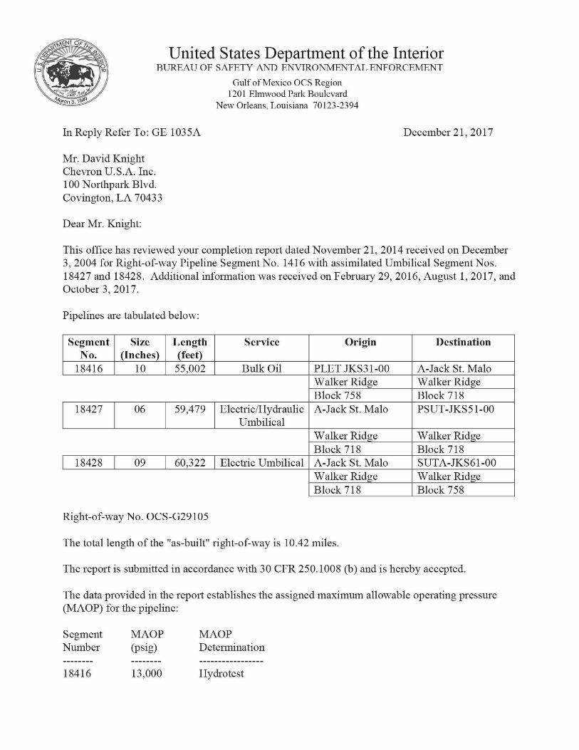
United States Department of the Interior BUREAU OF SAFETY AND ENVIRONMENTAL ENFORCEMENT Gulf of Mexico OCS Region 1201 Elmwood Park Boulevard New Orleans, Louisiana 70123-2394 In Reply Refer To: GE 1035A December 21, 2017 Mr. David Knight Chevron U.S.A. Inc. 100 Northpark Blvd. Covington, L A 70433 Dear Mr. Knight: This office has reviewed your completion report dated November 21, 2014 received on December 3, 2004 for Right-of-way Pipeline Segment No. 1416 with assimilated Umbilical Segment Nos. 18427 and 18428. Additional information was received on February 29, 2016, August 1, 2017, and Octobers, 2017. Pipelines are tabulated below: Segment No. Size (Inches) Length (feet) Service Origin Destination 18416 10 55,002 Bulk Oil PLET JKS31-00 A-Jack St. Malo Walker Ridge Walker Ridge Block 758 Block 718 18427 06 59,479 Electric/Hydraulic Umbilical A-Jack St. Malo PSUT-JKS51-00 Walker Ridge Walker Ridge Block 718 Block 718 18428 09 60,322 Electric Umbilical A-Jack St. Malo SUTA-JKS61-00 Walker Ridge Walker Ridge Block 718 Block 758 Right-of-way No. OCS-G29105 The total length of the "as-built" right-of-way is 10.42 miles. The report is submitted in accordance with 30 CFR 250.1008 (b) and is hereby accepted. The data provided in the report establishes the assigned maximum allowable operating pressure (MAOP) for the pipeline: Segment MAOP Number (psig) MAOP Determination 18416 13,000 Hydrotest
Transcript of United States Department of the Interior - BSEE Data … · 18416 13,000 Hydrotest . Page 2 ... JSM...
United States Department of the Interior BUREAU OF SAFETY AND ENVIRONMENTAL ENFORCEMENT
Gulf of Mexico OCS Region 1201 Elmwood Park Boulevard
New Orleans, Louisiana 70123-2394
In Reply Refer To: GE 1035A December 21, 2017
Mr. David Knight Chevron U.S.A. Inc. 100 Northpark Blvd. Covington, LA 70433
Dear Mr. Knight:
This office has reviewed your completion report dated November 21, 2014 received on December 3, 2004 for Right-of-way Pipeline Segment No. 1416 with assimilated Umbilical Segment Nos. 18427 and 18428. Additional information was received on February 29, 2016, August 1, 2017, and Octobers, 2017.
Pipelines are tabulated below:
Segment No.
Size (Inches)
Length (feet)
Service Origin Destination
18416 10 55,002 Bulk Oil PLET JKS31-00 A-Jack St. Malo Walker Ridge Walker Ridge Block 758 Block 718
18427 06 59,479 Electric/Hydraulic Umbilical
A-Jack St. Malo PSUT-JKS51-00
Walker Ridge Walker Ridge Block 718 Block 718
18428 09 60,322 Electric Umbilical A-Jack St. Malo SUTA-JKS61-00 Walker Ridge Walker Ridge Block 718 Block 758
Right-of-way No. OCS-G29105
The total length of the "as-built" right-of-way is 10.42 miles.
The report is submitted in accordance with 30 CFR 250.1008 (b) and is hereby accepted.
The data provided in the report establishes the assigned maximum allowable operating pressure (MAOP) for the pipeline:
Segment MAOP Number (psig)
MAOP Determination
18416 13,000 Hydrotest

Page 2
The high and low-pressure sensors shall be set no higher than 15 percent above and below the normal operating range, respectively. The high pilot, however, shall not be set higher than the MAOP of the pipeline. The pressure range shall be established by the use of pressure recorders.
The Right-of-way No. OCS-G29105 is described as follows:
A 200-foot wide right-of-way to operate and maintain a 10.75-inch bi-directional pipeline [PF-JKS-01], 10.42 miles in length, with two associated umbilicals [Segment Nos. 18427 and 18428] to transport bulk oil from a PLET [PLET JKS31-00] in Block 758 through Blocks 759, 760, 761, and 762 to FPU in Block 718, all located in the Walker Ridge Area.
Sincerely,
p l i w i A I Digitally signed by D I I V I / \ I _ DIMAI CUDCCTUA
SHRESTHA BIMAL SHRESTHA Date: 2017.12.21
leiiTios-oe'oo' For: Bryan A. Domangue
Acting Regional Supervisor Regional Field Operations

5r Chevron
Billy Varnado Project Director - Jack and St. Malo Chevron North America Deepwater Exploration & Projects
Chevron U.S.A. Inc. 1500 Louisiana Street Houston, TX 77002
November 21, 2014
Regional Supervisor, Field Operations Attn: Pipeline Section (GE 1035A) 1201 Elmwood Park Boulevard New Orleans, LA 70123-2394
RECEIVED DEC 0 2 2{m
Ofitm m nnifi npnwUum
Gentlemen:
In accordance with 30 CFR 250.1008(b), please find enclosed plats, hydrostatic test data, and
ASCII files for the JSM production pipelines as listed below. In accordance with NTL 2009-
Gl 5, a hard copy and CD with the digital data has been provided. The italicized and highlighted
future segments are not yet installed therefore details are not included at this time.
JACK Pipelines Segment Number
From To Service Permitted Length (ft)
As-Built Length (ft)
18415 (ROW) PLET-JKS32-00 (WR 758)
JSM FPU (WR 718)
Bulk Oil 58217 66726.95
18416 (ROW) PLET-JKS3 1 -00 (WR 758)
JSM FPU (WR 718)
Bulk Oil 57702 66202.09
18417 WellPSOOl (WR 758)
MFLD-JKS01-00 (WR 758)
Bulk Oil 102 Future
18418 Weil PS002 (WR 758)
MFLD-JKS01-00(WR 758)
Bulk Oil 1 115 115.61
18419 WellPS004(WR 758)
MFLD-JKS01-00 (WR 758)
Bulk Oil 102 Future
18420 Well PS005 (WR 758)
MFLD-JKS01-00 (WR758)
Bulk Oil 102 101.42
18421 MFLD-JKS01-00 (WR 758)
PTIS-JKS34-00 (WR 758)
Bulk Oil 130 131.17
18422 PTIS-JKS34-00 (WR 758)
PLET-JKS32-00 (WR 758)
Bulk Oil 120 117.57
18423 MFLD-JKS01-00 (WR 758)
PT1S-JKS33-00 (WR758)
Bulk Oil 117 120.40
18424 PT1S-JKS33-00 (WR 758)
PSTA-JKS41-00 (WR 758)
Bulk Oil 80 78.26
18425 PSTA-JK.S41-00 (WR 758)
PTIS-JKS33-00 (WR 758)
Bulk Oil 80 79.57
18426 PTIS-JKS33-00 (WR 758)
PLET-JKS31 -00 (WR758)
Bulk Oil 120 122.49

November 21, 2014 Page 2
ST.MALO Pipelines
Segment Number
From To Service Permitted Length (ft)
As-Built Length (ft)
18385 (ROW) PLET SMS32-00 (WR 677)
JSM Platfonn (WR718)
Bulk Oil 57345 65777.65
18386 (ROW) PLET SMS31-00 (WR677)
JSM Platfonn (WR718)
Bulk Oil 57851 66282.81
18387 WellPSOOl (WR 677)
MFLD-SMS02-00 (WR 677)
Bulk Oil 102 105.30
1S3SS Well PS002 {IVR MFLD-SMS02-00 (WR 677)
Bulk Oil 102 Future
18389 Well PS003 (WR677)
MFLD-SMS02-00(WR677)
Bulk Oil 102 103.49
18390 WellPS004(WR I " '
MFLD-SMS02-00 (WR 677)
Bulk Oil 102 Future
18391 PLET-SMS37-00 (WR 677)
MFLD-SMS02-00 (WR 677)
Bulk Oil 120 111.40
18392 PLET-SMS37-00 (WR 677)
MFLD-SMS02-00 (WR 677)
Bulk Oil 112 103.62
18393 WellPS005(WR 677)
MFLD-SMS01-00 (WR 677)
Bulk Oil us Future
18394 WallPS006(WR 67")
MFLD-SMS01-00 (WR 677)
Bulk Oil 117 Future
18395 WellPS007(WR MFLD-SMS01-00 (WR 677)
Bulk Oil 101 Future
18396 WellPSOOSfWR 677)
MFLD-SMS01-00 (WR 677)
Bulk Oil 103 Future
18397 MFLD-SMS02-00 (WR 677)
MFLD-SMS01-00(WR677)
Bulk Oil 130 137.32
18398 MFLD-SMS02-00 (WR 677)
MFLD-SMS01-00 (WR 677)
Bulk Oil 130 137.50
18399 MFLD-SMS01-00 (WR 677)
PT1S-SMS34-00 (WR 677)
Bulk Oil 118 117.29
18400 MFLD-SMS01-00 (WR 677)
PT[S-SMS33-00 (WR677)
Bulk Oil 120 116.61
18401 PTIS-SMS34-00 (WR677)
PLET-SMS32-00 (WR 677)
Bulk Oil 120 118.93
18402 PTIS-SMS33-00 (WR677)
PLET-SMS31-00 (WR 677)
Bulk Oil 120 114.44
18403 PTIS-SMS34-00 (WR 677)
PSTA-SMS42-00 (WR 677)
Bulk Oil 80 74.92
18404 PSTA-SMS42-00 (WR 677)
PT1S-SMS34-00 (WR 677)
Bulk Oil 80 75.86
18405 PTIS-SMS33-00 (WR677)
PSTA-SMS41-00 (WR 677)
Bulk Oil 80 76.21
18406 PSTA-SMS41-00 (WR 677)
PTIS-SMS33-00 (WR 677)
Bulk Oil 80 76.56
GC205 Juniper from LP Separator to Fuel Gas System
November 21, 2014 Page 3
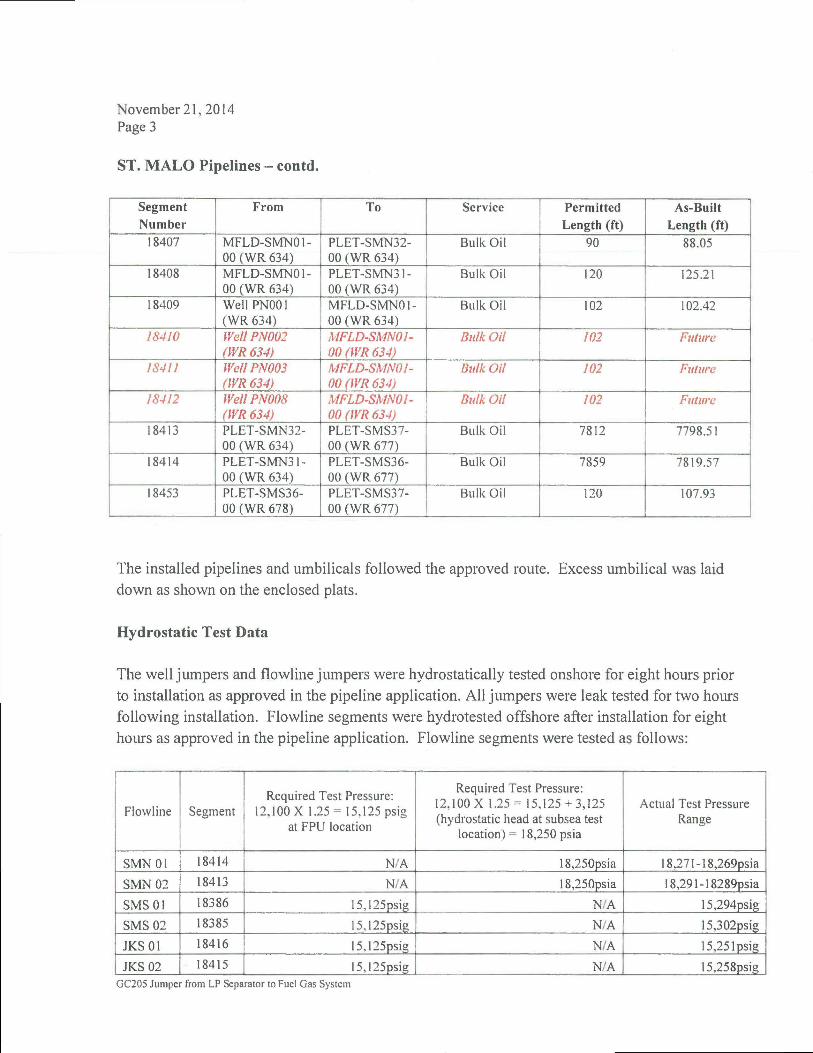
ST. MALO Pipelines - contd.
Segment Number
From To Service Permitted Length (ft)
As-Built Length (ft)
18407 MFLD-SMMH-00 (WR 634)
PLET-SMN32-00 (WR 634)
Bulk Oil 90 88.05
18408 MFLD-SMN01-00 (WR 634)
PLET-SM"N31-00 (WR 634)
Bulk Oil 120 125.21
18409 WellPNOOl (WR 634)
MFLD-SMN01-00 (WR 634)
Bulk Oil 102 102.42
18410 WellPN002 (WR634)
MFLD-SMN01-00 (WR 634)
Bulk Oil 102 Future
18411 WellPNOOS (WR 634)
MFLD-SMNOI-00 (WR 634)
Bulk Oil 102 Future
18412 WellPN008 (WR 634)
MFLD-SMN01-00 (WR 634)
Bulk Oil 102 Future
18413 PLET-SMN32-00 (WR 634)
PLET-SMS37-00 (WR 677)
Bulk Oil 7812 7798.51
18414 PLET-SMN31-00 (WR 634)
PLET-SMS36-00 (WR 677)
Bulk Oil 7859 7819.57
18453 PLET-SMS36-00 (WR 678)
PLET-SMS37-00 (WR 677)
Bulk Oil 120 107.93
The installed pipelines and umbilicals followed the approved route. Excess umbilical was laid down as shown on the enclosed plats.
Hydrostatic Test Data
The well jumpers and flowline jumpers were hydrostatically tested onshore for eight hours prior to installation as approved in the pipeline application. All jumpers were leak tested for two hours following installation. Flowline segments were hydrotested offshore after installation for eight hours as approved in the pipeline application. Flowline segments were tested as follows:
Flowline Segment Required Test Pressure:
12,100 X 1.25 = 15,125 psig at FPU location
Required Test Pressure: 12,100 X 1.25 = 15,125 + 3,125 (hydrostatic head at subsea test
location) = 18,250 psia
Actual Test Pressure Range
SMN 01 18414 N/A 18,250psia 18,271-18,269psia
SMN 02 18413 N/A 18,250psia 18,291-18289psia
SMS 01 18386 15,125psig N/A 15,294psig
SMS 02 18385 15,125psig N/A 15,302psig
JKS01 18416 I5,125psig N/A 15,251 psig
JKS02 18415 15.125psig N/A 15,258psig GC205 Jumper from LP Separator to Fuel Gas System

November 21, 2014 Page 4
Documentation of all hydrostatic tests is enclosed including logs for pressure, temperature, and corresponding calibration certificates for testing instruments. No documentation from leak testing is required to be submitted.
First Operation
First Operation of the pipeline system is scheduled to occur in November 2014.
[f you have any questions or need additional information, please contact Laura Hogge at 832-298-1185 or by email at 1 aura .ho n G£(o' chevron .com •
Please send approvals to the following: GOM Business Unit Chevron U.S.A., Inc. Attn: Joe Gordon 100 Northpark Blvd. Covington, LA 70433
David Knight Facilities Manager, Jack St. Malo Chevron USA, Inc.
Enclosures: PLAT's for Pipelines. Jumpers and Umbilicals Hydrotest Data ASCII Files
GC205 Jumper from LP Separator to Fuel Gas Sjslem

BAKER HUGHES
Acceptance Certificate
Project Information
Client: Chevron Baker Hughes Job No.: C-2079-13
Pipeline Owner: Chevron Client Work Order No.:
Project Name: JSM Pre-commissioning of flowlines and umbilicals
Client Contract No.: JSM-Z158-CTC-WAT-
CHV-000-00001-00
Pipeline Name: JKS-01 Launch Site: N/A
Location: St Malo South Receiving Site: N/A
Service Description: Hydrotest of JKS-01 Section #18416
Start Date: 20-Feb-2014 Service Description: Hydrotest of JKS-01 Section #18416
Completion Date: 24-Feb-2014
Baker Hughes certifies that the described service to the pipeline was completed in accordance with the parameters represented within this document.
Pipel ine Information A c c e p t a n c e Criteria & R e s u l t s
Length: 12.258 mi Specification (if applicable):
Hydrotest of JKS-01 with an 8-hour hold with no unexplainable loss.
Nominal Diameter: 10.75 in
Specification (if applicable):
Hydrotest of JKS-01 with an 8-hour hold with no unexplainable loss.
Wall Thickness: 1.25 in Specification Achieved: 231615FEB14 - 240030FEB14
Internal Diameter: 8.25 in Date Accepted: 24-Feb-2014
Section # (if applicable): Time Accepted: 0030
Instrumentation
Description Range Serial # Unit# Manufacturer Calibration Date
Calibration Certificate
Digital Pressure Gauge 0-20,000 psi 12230 Keller America 21-Jan-2014 Digital Pressure Gauge 0-20,000 psi 12227 Keller America 10-Jan-2014
Comments
Hold Period: 231615FEB14 -240030FEB14. Pressure maintained at 15,251 psig
BHI Representative: MarkJr ifhidt Client Representative: Ejtck Segarra Pipeline Owner Signature: Signature: Signature:
Date: Date: Date:
Distribution: Original On Site Job File Page 1 of 1 Document No.: PPS / OPS / 0376

BAKER HUGHES
Commencement Certificate
Project Information
Client: Chevron Baker Hughes Job No.: C-2079-13
Pipeline Owner: Chevron Client Work Order No.:
Project Name: JSM Flooding and Hydro Client Contract No.:
Pipeiine Name: JKS-01 Launch Site:
Location: Receiving Site:
Service Description: Flood JKS-01 pipeline Start Date: Service Description: Flood JKS-01 pipeline
Completion Date:
Baker Hughes certifies that the above described service can proceed on the described pipeiine in accordance with the procedures, relevant CVI's, and parameters represented within this document. All related activities required for commencement will be completed to the applicable standard.
Pipeline Information Acceptance Criteria & Results
Length: 66,215 ft Min. Internal Diameter: 8.25 in
Nominal Diameter: 10.75 in Min. Bend Radius:
Wall Thickness: 1.25 In Section # (if applicable):
Procedures
C-2079-13-BHI-PRO-006
Confirmation of Verbal Instructions (CVI)
N/A
Other Standards, Instructions or Applicable Documentation N/A
Comments
Flooding JKS-01 with the Remote Flooding Module, as per procedure.
BHI Representative: Mark E Schmidt . Client Representative: Erick Segarra Pipeline Owner
Signature: Signature: Signature:
Date: 13-Feb-2014 Date: Date:
Distribution: Original Copy #1 Copy #2
On Site Job File Baker Hughes Office Client
1 of 1
© Baker Hughes Incorporated. All Rights Reserved.
Document No.: PPS / OPS / 0375 Revision No.: E
Date: August 2012

! i « Chevron ! i « Operation: JKS-01 Flood
BAKER HUGHES
Date: 13 FEB 2014-14 FEB 2014 Start Time: 14:24 End Time: 00:18
Injected Filtered Water (Gallons)
Chemical (PPM)
Temperature (C)
14:00 15:00 13/02/2014
16:00 17:00 18:00 19:00 Time 20:00
- i — i — | — i — i — | — i — r
21:00
_ in o
h o _ + a
in I- o o +^
\- o o + F a>
in
Signature: -S&ffifj
' 1 1 1 1 I 1 ' 1 ' 1 I ' 22:00 23:00 00:00
14/02/2014
Date: ^ ^ 7 ^
Date: i2£^ML
Baker Rep: Mark E Schmidt
Client Rep: Erick Segarra Signature:

JKS-01 Hydrotest
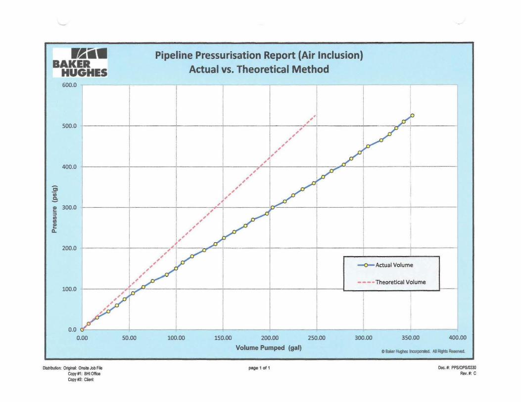
B A K E R Pipeline Pressurisation Report (Air Inclusion) Actual vs. Theoretical Method
Project In format ion
Client: Chevron Baker Hughes Job No.: C-2079-13
Pipeline Owner: Chevron Client Work Order No.:
Project Name: JSM - SMN Client Contract No.:
Location: JKS-01 Pipeline Volume: 179.727 gal
Length: 12.258 mile Volume/Stroke: gal
Outside Diameter: 10.75 inch Start Date: 20-Feb-2014
Section #: 1 of 1 Completion Date: 20-Feb-2014
Date Time Pressure
Actual Cumulative
Volume injected
Theoretical Volume
(P)(AV/AP)
Pipe Temp.
Remarks
(dd-Mon-yyyy) (24:00) (psig) (gal) (gal) (0F)
20-Feb-2014 19:22 0.00 0.000 0.000 Start of Pressurisation 20-Fel>-2014 19:24 15.00 7.000 7.097 20-Feb-2014 19:26 30.00 16.000 14.193 20-Feb-2014 19:28 45.00 28.000 21.290 20-Feb-2014 19:30 60.00 37.000 28.386 20-Feb-2014 19:31 75.00 45.000 35.483 20-Feb-2014 19:32 90.00 54.000 42.579 20-Feb-2014 19:34 105.00 65.000 49.676 ***Ambienl Temperature 82F for Air Inclusion Test*** 20^66-2014 19:36 120.00 75.000 56.772 20-Fet>-2014 19:38 135.00 90.000 63.869 20-Fet>-2014 19:39 150.00 100.000 70.965 20-Feb-2014 19:40 165.00 107.000 78.062 20-Fet}-2014 19:41 180.00 117.000 85.158 20-Feb-2014 19:42 195.00 130.000 92.255 20-Feb-2014 19:43 210.00 142.000 99.351 20-Feb-2014 19:44 225.00 151.000 106.448 20-Feb-2014 19:45 240.00 162.000 113.544 20-Fet>-2014 19:46 255.00 174.000 120.641 20-Feb-2014 1947 270.00 182 000 127.737 20-Feb-2014 19:48 285.00 197.000 134.834 20-Feb-2014 19:49 300.00 203.000 141.930 20-Feb-2014 19:50 315.00 216.000 149.027 20-Feb-2014 19:51 330.00 225.000 156.123 20-Feb-201'l 19:52 345.00 235.000 163.220 20-Feb-2014 19:63 360.00 247.000 170.317 20-Feb-2014 19:54 375.00 257.000 177.413 20-Fet>-2014 19:55 390.00 266.000 184.510 2O-Feb-2014 19:56 405.00 279.000 191.606 20-Fet>-2014 19:57 420.00 287.000 198.703 20-Feb-2014 19:58 435.00 296.000 205.799 20-Fet)-2014 19.59 450.00 305.000 212.896 20-Feb-2014 20:00 465.00 319.000 219.992 20-Feb-2014 20:01 480.00 328.000 227.089 20-Feb-2014 20:05 495.00 335.000 234.185 20-Feb-2014 20:06 510.00 343.000 241.282 20-Fet)-2014 20:07 525.00 352.000 248.378
- va = v l
Distribution: Original
Copy #1
Copy #2
On Site Job File
Baker Hughes Office
Client
Page 1 of 5
© Baker Hughes Incorporated. All Rights Reserved.
Document No.: PPS / OPS 10330
Revision No.: E
Revision Date. July 2012

Pipeline Pressurisation Report (Air Inclusion) -B H U G H E S Actual vs. Theoretical Method
Pipel ine Vo lume Calculat ion
TT= Pi = 3.14159
r = ID/2 = Internal Pipeline Radius = 4.13 inch V = 7T ( r 2 )L
L = Pipeline Length = 12.258 mile V = 7T ( r 2 )L V = Total Pipeline Volume = 179,727.01 gal
Note: For Pipelines of varied length and diameter, the Total Pipeline Volume is a summation of the above calculation for each section.
AV / AP Calculat ions
Check a sinqle Box below to indicate ApDlicable Pipeline Condition (multiple conditions require analysis outside this form to determine AV/ AP):
Se/ectecM\/,MP= 0.47310
• 1 - Restrained (i.e., buried) A V
0.47104 gal/psig
n 2 - Unrestrained (i.e., not buried or anchored)
*v=v AP
0.47310 gal/psig
l—| 3 - Terminated (i.e., anchored)
AV 0.46795 gal/psig
Where: Description
(Enter job-specific values below in place of defaults, as needed)
Calculated Pipeline Fill Volume V = 179727.01 gal Theoretical Volume AV Required to Pressurise to AP AV= 7.097 gal Incremental Pressure AP = 15.0 psig Wall Thickness t = 1.25000 inch Young's Modulus (For carbon steel) E = 3.00E+07 psig Compressibility of Fluid - (note: ft = 1/K, i.e., Compressibility is reciprocal of Bulk Modulus)
« = 2.360E-06 psi
Poisson Ratio (For carbon steel) - Dimensionless u = 0.30 non-dimensional Outside diameter OD = 10.7500 inch Note: Alternative pressure ranges can be used. Adjust the above values accordingly for the actual data range used.
Air Inclusion Calculations
vn =
v1 =
v ^
Actual Volume =
Theoretical Volume =
V = Total Pipeline Volume =
Volume of Air % =
352.000 gal
248.378 gal
179,727.01 gal
0.06 %
Vair = ( va.v t)
V (100)
ACCEPTABLE Acceptable Air Content < 0.2%
Distribution: Original On Site Job File
Copy #1 Baker Hughes Office
Copy #2 Client
Page 2 of 5
© Baker Hughes Incorporated. All Rights Reserved.
Document No.: PPS / OPS / 0330
Revision No.: E
Revision Date: July 2012

Pipeline Pressurisation Report (Air Inclusion) Actual vs. Theoretical Method
Theoretical Air Content Graph
0.00 050 1.00 1.50 2.00
Volume Pumped m3
2.50 3.00
Comments Ambient temperature 82F.
Original: On Site Job Rio
Copy#1 : Baker Hughes Office
Copy #2 : Client
Pago 3 o l 5
© Baker Hughes Incorporated. All Rights Reserved.
Document No.: P P S / O P S / 0 3 3 0
Revision No.: E
Revision Date: July 2012

B A K E R H U G H E S
Pipeline Pressurisation Report (Air Inclusion) Actual vs. Theoretical Method
Instrumentation
Description Range Serial # Unit# Manufacturer Calibration Date Calibration Certificate
Dead Weight Gauge Pressure Recorder 0-20k 4786 Tec] Cal 1/21/2014 Yes Pressure Gauge 0-20k 12230 Keller 1/21/2014 Yes
Temp. Recorder - Ambient 40F-150F 20804 Barton 10/10/2013 Yes Temp. Recorder - Pipewall Temp. Recorder - Ground
BHI Representative: Jay Forte ,,, u... , Client Representative: System Owner: Signature: Signature: f t J M — ^ Signature:
Date: 2/20/14 Date: Date:
) Distribution: Original: On Site Job File
Copy#1: Baker Hughes Office
Copy #2. Client
Page 4 of 5
© Baker Hughes Incotporafed. All Rights Reserved.
Document No.: PPS / OPS / 0330
Revision No.: E
Revision Date: July 2012
r BAKER HUGHES
Pipeline Pressurisation Report (Air Inclusion) Actual vs. Theoretical Method
600.0
500.0
400.0
'55 a
2 300.0 3 in m 2 a.
200.0
100.0
0.0
0.00 50.00 100.00 150.00 200.00 250.00
Volume Pumped (gal)
0
*
t s
•
* * * *
*
/ / * * * * *
*
* * *
*
•
* * —O—Actual Volume
- - - -Theoret ica l Volume
D
300.00 350.00 400.00
© Baker Hughes Incorporatei All Rigfits Reseived.
Distribution: Original: Onsite Job File Copy#1: BHI Office Copy #2: Client
page 1 of 1 Doc.* PPS/OPSA)330 Rev.#: C

Chevron mtMmW
BAKER Operation: JKS-01 Hydrostatic Test (Hold Period and Depressurization) mtMmW
BAKER Date: 23 FEB 2014 - 24 FEB 2014
HUGHES Start Time: 14:00 End Time: 07:59
18.0M
17.5X1
ROM
16.530
1S.MC
USX
1E.0X
14.ejc
14.0)0
13.5»
12.0«
1Z.5X
» 1J.0M a
11.SX
11.0X
10.5)0
10.030
9.53C
S,O30
8,5)0
i.0X
7.5)C
7,0)0
6.5)0
1 : : :
Siv*-n|}r.« ms - irrmu OPHi 50- '2 00:15 A« QMQ
Pressure
Temperature •115 00
11000
105.00
100.00
Kao
sow
?soc
MOC
75 00
70W
ej.Dc
eooc ^
SS.00
50.00
iSX
•OflO
am MM
.'500
:ooc
•15O0
1000
! Dt
COO 2MBM Z382rM 2V02U
IT OOO! II00 X BMM zioau anM ZME/I* I ; : : ' . : 2MMe 21 »o« sjoew :3 oc co ...... 24*2/H
orco« MCBM 3:«-eo 03OC0O
Baker Rep: Mark E Schmidt
Client Rep: Erick Segarra
Signature:
Signature: 7^
Date: ^ > ^ / V
Date:

Chevron
maimm BAKER
Operation: JKS-01 Hydrostatic Test maimm BAKER
Date: 20 FEB 2014 - 24 FEB 2014
HUGHES Start Time: 19:19 End Time: 07:59
M.JK
PSH I'.DOO
tfijN 16.3W
15.500
15.300
IfrOC
11.300
13,500
I3.70C
12,500
12.360
11,500
11,300
10.500
IMN 9.5«
S.D0C
8.500
8.300
'.500
'.360
e.soc 6.300
5,5« 5,360
4,500
1,300
3,500
3.300
2.500
2.360
1.50C
1.300
500
0
-500
-1.300
-'. r:c
SavtJcMrv* (60-b m i t t A U P ' r 06-12:0015 £M
;::: ....
7800
77 00
76 00
7500
74 00
73 00
7200
7100
70 00 l -•• esoc
€700
esoo
€4 00
era
€200
eioo
::::
Pressure
Temperature
20TO.U 180Dfl3
tW4 SOKOO
21132.14 21/32/14 12 30 OC
2mi4 SA2'14 22«2fl« Om* TUCnt OM»30 I C M M 12M30 -gCOOO 03M36
9ipM 23*2^4 TSW/-* umu tutOM 06:CO00 12-0306 18 6C0fl 00 00 03 %KtO
WBG M 120OO3
Baker Rep: Mark E Schmidt
Client Rep: Erick Segarra
Signature: ^
Signature: / / ^
Date: J<//&>/V
Date: ^ ^ / /

r BAKER
HUGHES 4101 Oates road Houston, Texas 77013
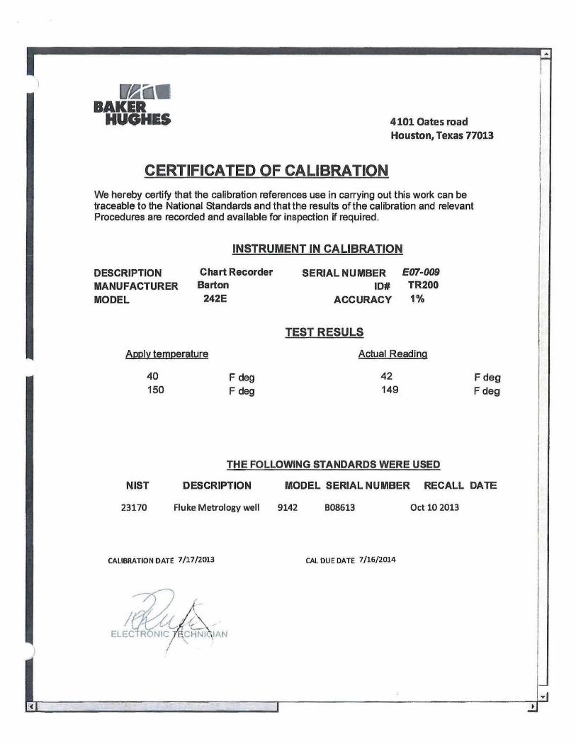
CERTIFICATED OF CALIBRATION We hereby certify that the calibration references use in carrying out this work can be traceable to the National Standards and that the results of the calibration and relevant Procedures are recorded and available for inspection if required.
INSTRUMENT IN CALIBRATION
DESCRIPTION MANUFACTURER MODEL
Chart Recorder Barton
242E
SERIAL NUMBER 20804 ID# TR203
ACCURACY 1%
Apply temperature
40 F deg 150 Fdeg
TEST RESULS
Actual Reading
40 149
F deg Fdeg
r
THE FOLLOWING STANDARDS WERE USED
NIST DESCRIPTION MODEL SERIAL NUMBER RECALL DATE
23170 Fluke Metrology well 9142 B08613 Oct 10 2013
CALIBRATION DATE 5/8/2013 CAL DUE DATE 5/7/2014
ELECTRONIC "mCHNlOvlAN
r HUGHES 4101 Oates road
Houston, Texas 77013
CERTIFICATED OF CALIBRATION We hereby certify that the calibration references use in carrying out this work can be traceable to the National Standards and that the results of the calibration and relevant Procedures are recorded and available for inspection if required.
INSTRUMENT IN CALIBRATION
DESCRIPTION MANUFACTURER MODEL
Chart Recorder Barton
242E
SERIAL NUMBER E07-009 ID# TR200
ACCURACY 1%
Apply tempergture
40 F deg 150 F deg
TEST RESULS
Actual Reading
42 149
Fdeg Fdeg
THE FOLLOWING STANDARDS WERE USED
NIST DESCRIPTION MODEL SERIAL NUMBER RECALL DATE
23170 Fluke Metrology well 9142 B08613 Oct 10 2013
CALIBRATION DATE 7/17/2013 CAL DUE DATE 7/16/2014
ELECTRONIC 7HCHNK\IAN

iffechCal Establiihwl 1964
Tech Cal Recorder™ Certificate of Caiibration
This is to certify that this pressure and/or temperature recorder has been manufactured and calibrated in accordance with Technology & Calibrations, Inc.'s quality assurance program, current revision. All measurements are traceable to the National Institute of Standards and Technology (NIST) and certified in accordance with ANSI/NCSL, Z540-1 and IS010012-1. All calibrations performed at 72 degrees Fahrenheit, plus or minus 4 degrees and less than 65% relative humidity. The collective uncertainty of the measurement standard does not exceed 25% of the acceptable tolerance for each characteristic of the measuring and test equipment being certified.
Model Number: 1B700 Serial Number: 04786
Pen 1 Range: 20,000 PSI Pen 2 Range: N/A Pen 3 Range: N/A
The Accuracy of this Recorder is +/- 0.5% of Indicated Range*
Customer "In Service Date": Date of Caiibration: Jan 21,2014
Calibration Due Date:
Technician: M. Resales OA Approval: This certificate shall not be reproduced except In full, without the written approval of Tech Cal.
WARRANTY Tech Cal Recorders are warranted against defective materials or workmanship for 12 months following the date of shipment. Technology & Calibration, Inc.'s liability is limited to repair or replacement at the factory. No obligation can be assumed for recorders subjected to misuse or unauthorized repairs.
Technology & CallbroUon, Ino. - 3638 Plnemont Drive, Houston, Texan 7701S USA www.taehoBl.oom • 888-640-6806 loll free

WechCal Establnhod 1964
Tech Cal Recorder™ Certificate of Calibration
This is to certify that this pressure and/or temperature recorder has been manufactured and calibrated in accordance with Technology & Calibrations, Inc.'s qualify assurance program, current revision. All measurements are traceable to the National Institute of Standards and Technology (NIST) and certified in accordance with ANSI/NCSL, Z540-1 and IS010012-1. All calibrations performed at 72 degrees Fahrenheit, plus or minus 4 degrees and less than 65% relative humidity. The collective uncertainty of the measurement standard does not exceed 25% of the acceptable tolerance for each characteristic of the measuring and test equipment being certified.
Model Number: 1B700 Serial Number: 04785
Pen 1 Range: 20,000 PSI Pen 2 Range: N/A Pen 3 Range:
T h e Accuracy of this Recorder is •*-/- 0.5% of Indicated Range*
Customer "In Service Date'*: _
Calibration Due Date: Date of Calibration: Jan 21,2014
Technician: M. Resales OA Approval:
This certificate shall not be reproduced except In full, without the written approval of Tech Cal.
N/A
WARRANTY Tech Cal Recorders are warranted against defective materials or workmanship for 12 months following the date of shipment Technology & Calibration, Inc.'s liability Is limited to repair or replacement at the factory. No obligation can be assumed for recorders subjected to misuse or unauthorized repairs.
Tochnolofly a CollbraUcm, Inc. - 3638 Plnamont Drhra, Houston, Texaa 77018 USA www.techcal.aom - 888-6484608 tall free

KER HUGHES
4101 Oates Road Houston, Texas 77013
CERTIFICATE OF CALIBRATION
The manufacturer's specifications for the below instrument have been confirmed by comparation to standards which are regularly calibrated using accepted values of natural physical constansts, ratio type self -calibrating techniques, comparasion to standards whish are traceable to National Institute of Standards and Technology (NIST), or compared to consensus standards
INSTRUMENT IN CALIBRATION
TEST RESULTS
Applied Pressure PSIG
0 19000
Actual Reading
0.00 18990
THE FOLLOWING STADARDS WERE USED
NIST DESCRIPTION MANUF MODEL 26534 Digital Gauge Keller America Leo Rec
S/N 9101
RECALL DATE Nov 15 2014
Calibration i bate 7 January 21 2014 Cal Due Date January 20 2015
Roberto Romero Electronic Tech
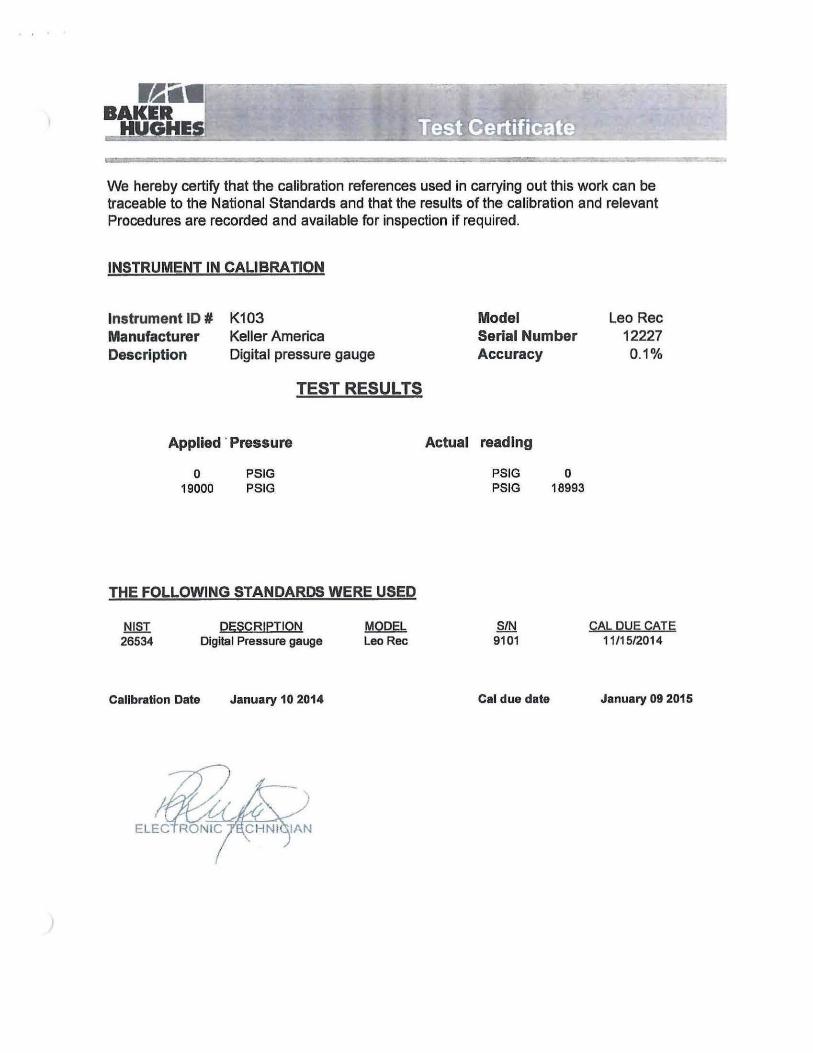
BAKER HUGHES Test Certificate
We hereby certify that the calibration references used in carrying out this work can be traceable to the National Standards and that the results of the calibration and relevant Procedures are recorded and available for inspection if required.
INSTRUMENT IN CALIBRATION
Instrument ID # Manufacturer Description
K103 Keller America Digital pressure gauge
Model Serial Number Accuracy
Leo Rec 12227 0.1%
T E S T R E S U L T S
Applied Pressure Actual reading
o 19000
PSIG PSIG
PSIG PSIG
0 18993
THE FOLLOWING STANDARDS WERE USED
NIST DESCRIPTION MODEL 26534 Digital Pressure gauge Leo Rec
S/N 9101
CAL DUE CATE 11/15/2014
Calibration Date January 10 2014 Cal due date January 09 2015
ELECTRONIC THCHNIGIAN

BMS 2.2.1 Production Flowline PF-JKS-01 and Production Riser PR-JKS-01
The table below presents the pipeline main information.
Table 3: JKS-01 Hydrostatic Testing Information
Chevron
Table 4: JKS-01 Hydrostatic Testing Chemical Information
The pressurization rate for the flowline is as follows:
Production Flowline (Hydro) JKS-01
Chemical Product ion
Flowl ine
Vpiessurfze
n , 3
PPM Vchemlca l Vcheinical
m Vchemlca l T o t a l
i i i
Glutaraldehyde PF-JKS-01 29.106
80 0.0028 0.7381
0.8323 Glutaraldehyde PR-JKS-01 3.714
80 0.0004 0.0942
0.8323
Dye PF-JKS-01 29.106
100 0.0034 0.9226
1.0404 Dye PR-JKS-01 3.714
100 0.0004 0.1178
1.0404
Flowl ine Subsea Test Pressure (psig)
PF-JKS-01 / PR-JKS-01 15,245
Range Pressure (psig)
Time to reach (15 psi/min)
Duration
0 psig - 500 psig 500 33 minutes 15 Minutes - Air Inclusion Test
500 psig - 50% TP 7,623 8.47 hours 15 Minute Hold 50% TP - 75% TP 11,434 12.70 hours 15 Minute Hold
75% TP - 95% TP 14,483 16.09 hours 15 Minute Hold
95% TP - 100% TP 15,245 16.94 hours 8 Hour Hold
Document Number: C-2079-13-BHI-PRO^)17
Action Items Oil Chevron
1. Obtain Permit to Work to carry out operations. Perform JHA / Toolbox talk to carry out operations. Ensure all personnel are aware of permit requirements and all has signed JHA. Perform JHA / Toolbox talk each shift change or as required throughout operations. Only personnel involved with the operations will be allowed within the work area.
A A
Page 8 of 27

Chevron
BAKER HUGHES
Task Description
2/2.9 ff^
2. BH PMG will set up topside hydrotest skid in accordance with BH PMG Drawing, C-2079-13-BHI-DRG-002
A
<
3. FPU ROV will connect the 3A" Pressurization hose to the pull in head
A
CAUTION BH PMG must flow water through the V* pressurization hose prior to hydrotest operations.
NOTE BH PMG will use treated / filtered seawater to pressurize the flowline.
4. BH PMG must conduct a temporary leak test of their hydrostatic test skid in order to ensure there are no leaks.
A
5. BH PMG and Chevron to confirm that the valves are in the proper order to begin Hydrostatic Testing operations.
A W
NOTE In the event of unexplained pressure loss during any hold period, the vessel and ROV will flag the line to determine the source of the pressure loss.
6. Upon confirmation from Chevron, BH PMG will begin to pressurize the production flowline to 500 psig.
o Pressurize up to maximum of 15 psig/min o Log Pressure and Volume injected every five
(5) minutes on Pressurization Report (C-2079-13-BHI-PRO-002. Attachment 9)
A A
It A
/
7. BH PMG will stop pressurization at 500 psig and set the valves for stabilization / hold. During the fifteen minute hold, the ROVs are to survey the pressurized lines and fittings for evidence of dye, and BH PMG will conduct an Air Inclusion Calculation (C-2079-13-BHI-PRO-002, Attachment 8).
A A
I t
NOTE Acceptable Air Content for a previously pigged line is 0.2%. This is calculated by the ratio of Actual Volume to Pressurize vs. Theoretical Volume to Pressurize.
CAUTION Lock open valve on PRV in order to ensure it is part of the system (caution tape).
CAUTION Ensure Keller Gauges are cleared out and ready to collect data
Action Items Oil
i V
Document Number: C-2079-13-BHI-PRO-017
HA. REV 02 Page 9 of27

Chevron
HUGHES 1 Description Action Items
NOTE Should the Air Inclusion Test Fail, BH PMG and the client will determine how to proceed with the test
Umltm
8. Upon achieving an acceptable air inclusion. Chevron and BH PMG Leads will sign the Air Inclusion Form. Once this is completed, BH PMG will begin to pressurize the flowline to 50% of test pressure,
o Pressurize up to maximum of 15 psig/min o Log Pressure and Volume injected every
fifteen (15) minutes on Pressurization Report (C-2079-13-BHI-PRO-002. Attachment 9)
A
#
A
Umltm 9. BH PMG will stop pressurization at 50% test pressure
and to set the valves for stabilization / hold. During the fifteen (15) minute hold, the ROVs are to survey the pressurized lines and fittings for evidence of dye.
A W r 1
10. On completion of fifteen (15) minute hold period with no signs of leakage, BH PMG will set the valves for pressurization and resume pressurization to 75% test pressure.
o Pressurize up to maximum of 15 psig/min o Log Pressure and Volume injected every
fifteen (15) minutes on Pressurization Report (C-2079-13-BHI-PRO-002. Attachment 9)
A W Qtrf
11. BH PMG will stop pressurization at 75% test pressure and to set the valves for stabilization / hold. During the fifteen (15) minute hold, the ROVs are to survey the pressurized lines and fittings for evidence of dye.
A W
12. On completion of fifteen (15) minute hold period with no signs of leakage, BH PMG will set the valves for pressurization and resume pressurization to 95% test pressure.
o Pressurize up to maximum of 15 psig/min o Log Pressure and Volume injected every
fifteen (15) minutes on Pressurization Report (C-2079-13-BHI-PRO-002. Attachment 9)
A
Of
w
13. BH PMG will to stop pressurization at 95% test pressure and to set the valves for stabilization / hold. During the fifteen (15) minute hold, the ROVs are to survey the pressurized lines and fittings for evidence of dye.
A
mm c
D
Document Number: C-2079-13-BHI-PRO-017 REV 02 Page 10 of 27

Chevron
HUGHES
pirn
Task Description Action Items BH ON Chevron
PMG
14. On completion of fifteen minute hold period with no signs of leakage, BH PMG will set the valves for pressurization and resume pressurization to 100% test pressure. BH PMG will use the DHDA pump to complete the pressurization.
o Pressurize up to maximum of 15 psig/min o Log Pressure and Volume injected every five
(5) minutes on Pressurization Report (C-2079-13-BHI-PRO-002. Attachment 9)
A w 9
15. BH PMG will stop pressurization at 100% test pressure and to set the valves for stabilization / hold,
o Begin Stabilization Period (8 hours) o Close Valve leading to Pump (next to check
valve) o Log Pressure every fifteen (15) minutes on
Pressurization Report (C-2079-13-BHI-PRO-002, Attachment 9)
A W - n ,
16. Upon the completion of the Stabilization Period, BH PMG and Chevron must have concurrence that all test objectives were met.
A
#
A ^
17. BH PMG will confirm with Chevron that the depressurization may begin.
A A ^
18. BH PMG aligns the valves for depressurization. o Depressurization to occur at a maximum rate
of 30 psig / min o Log Pressure and Volume injected every
fifteen (15) minutes on Pressurization Report fC-2079-13-BHI-PRO-002. Attachment 9)
A A W Qey
NOTE In order to depressurize the system. Oil (vessel) will place a hot stab, fitted with a needle choke valve, on the PLET.
19. ROV will ensure valve is open to the correct position and then slowly open the Flooding Cap on the PLET
BH PMG will monitor depressurization at the FPU.
A w A &4
20. BH PMG and Chevron confirm depressurization has been reached, using instrumentation on FPU.
A A r y \
J 21 Recover depressurization hot stab. A
or-A A >
22. FPU ROV to recover YA" hose. A
Document Number: C-2079-13-BHI-PRO-017 REV Q2 f f f Page 11 of27

HUGHES
C9oo
Chevron
Task Descr ipt ion • Action Items Oil Chevron
23. BH PMG and Chevron will confirm the data is intact and downloaded to a computer.
A A
24. Upon acceptance of the test, Chevron and BH PMG will sign the Test Acceptance Certificate for JKS-01, C-2079-13-BHI-PRO-002. Attachment 12.
A A
/?//« M-fv // Bottom of this page is intentionally left blank //
Document Number: C-2079-13-BHI-PRO-017 REV 02 Page 12 of 27

Test Window
Date and Time Pressure
(psici) Rate
(psi/min) Notes
2/20/14 19:22 0 Begin Pressurization 2/20/14 19:30 60 7.50 Ambient Temp = 82° 2/20/14 19:34 105 11.25 2/20/14 19:40 165 10.00 2/20/14 19:45 240 15.00 2/20/14 19:50 315 15.00
2/20/2014 19:55 390 15.00 2/20/2014 20:00 465 15.00 2/20/2014 20:05 495 6.00 2/20/2014 20:07 525 15.00 Stop for Air Inclusion; Air Inclusion = 0.06% Pass 2/20/2014 22:00 761 15.73 2/20/2014 22:15 943 12.13 2/20/2014 22:30 1,150 13.80 2/20/2014 22:45 1,301 10.07 2/20/2014 23:00 1,490 12.60 2/20/2014 23:15 1,680 12.67 2/20/2014 23:30 1,870 12.67 2/20/2014 23:45 2,067 13.13 2/21/2014 0:00 2,250 12.20 2/21/2014 0:15 2,422 11.47 2/21/2014 0:30 2,618 13.07 2/21/2014 0:45 2,792 11.60 2/21/2014 1:00 2,980 12.53 2/21/2014 1:15 3,170 12.67 2/21/2014 1:30 3,340 11.33 2/21/2014 1:45 3,515 11.67 2/21/2014 2:00 3,675 10.67 2/21/2014 2:15 3,860 12.33 2/21/2014 2:30 4,015 10.33 2/21/2014 2:45 4,200 12.33 2/21/2014 3:00 4,344 9.60 2/21/2014 3:15 4,518 11.60 2/21/2014 3:30 4,699 12.07 2/21/2014 3:45 4,868 11.27 2/21/2014 4:00 5,065 13.13 2/21/2014 4:15 5,242 11.80 2/21/2014 4:30 5,415 11.53 2/21/2014 4:45 5,600 12.33 2/21/2014 5:00 5,760 10.67 2/21/2014 5:15 5,950 12.67 2/21/2014 5:30 6,140 12.67 2/21/2014 5:45 6,350 14.00 2/21/2014 6:00 6,565 14.33 2/21/2014 6:15 6,760 13.00 2/21/2014 6:30 6,900 9.33 2/21/2014 6:45 7,180 18.67 2/21/2014 7:00 7,250 4.67 2/21/2014 7:15 7,428 11.87 2/21/2014 7:30 7,593 11.00 2/21/2014 7:35 7,629 7.20 50% Hold. Hold for 20 minutes, no appreciable loss 2/21/2014 8:30 7,750 8.07 2/21/2014 8:45 7,919 11.27 2/21/2014 9:00 8,151 15.47 2/21/2014 9:15 8,289 9.20
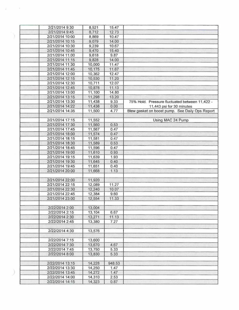
2/21/2014 9:30 8,521 15.47 2/21/2014 9:45 8,712 12.73
2/21/2014 10:00 8,869 10.47 2/21/2014 10:15 9,079 14.00 2/21/2014 10:30 9,239 10.67 2/21/2014 10:45 9,470 15.40 2/21/2014 11:00 9,618 9.87 2/21/2014 11:15 9,828 14.00 2/21/2014 11:30 10,000 11.47 2/21/2014 11:45 10,175 11.67 2/21/2014 12:00 10,362 12.47 2/21/2014 12:15 10,530 11.20 2/21/2014 12:30 10,711 12.07 2/21/2014 12:45 10,878 11.13 2/21/2014 13:00 11,100 14.80 2/21/2014 13:15 11,298 13.20 2/21/2014 13:30 11,438 9.33 75% Hold. Pressure fluctuated between 11,422 -
11,443 psi for 30 minutes 2/21/2014 14:22 11,438 0.00 75% Hold. Pressure fluctuated between 11,422 -
11,443 psi for 30 minutes 2/21/2014 14:35 11,500 4.77 Blew gasket on boost pump. See Daily Ops Report
2/21/2014 17:15 11,552 Using MAC 24 Pump 2/21/2014 17:30 11,560 0.53 2/21/2014 17:45 11,567 0.47 2/21/2014 18:00 11,574 0.47 2/21/2014 18:15 11,581 0.47 2/21/2014 18:30 11,589 0.53 2/21/2014 18:45 11,596 0.47 2/21/2014 19:00 11,610 0.93 2/21/2014 19:15 11,639 1.93 2/21/2014 19:30 11,645 0.40 2/21/2014 19:45 11,651 0.40 2/21/2014 20:00 11,668 1.13
2/21/2014 22:00 11,920 2/21/2014 22:15 12,089 11.27 2/21/2014 22:30 12,240 10.07 2/21/2014 22:45 12,384 9.60 2/21/2014 23:00 12,554 11.33
2/22/2014 2:00 13,004 2/22/2014 2:15 13,104 6.67 2/22/2014 2:30 13,271 11.13 2/22/2014 2:45 13,380 7.27
2/22/2014 4:30 13,576
2/22/2014 7:15 13,600 2/22/2014 7:30 13,670 4.67 2/22/2014 7:45 13,750 5.33 2/22/2014 8:00 13,830 5.33
2/22/2014 13:15 14,228 948.53 2/22/2014 13:30 14,250 1.47 2/22/2014 13:45 14,272 1.47 2/22/2014 14:00 14.310 2.53 2/22/2014 14:15 14,323 0.87

2/22/2014 14:30 14,360 2.47 2/22/2014 14:45 14,380 1.33 2/22/2014 15:00 14,400 1.33 2/22/2014 15:15 14,405 0.33 2/22/2014 15:30 14,415 0.67 2/22/2014 15:45 14,425 0.67 2/22/2014 16:00 14,431 0.40 2/22/2014 16:15 14,440 0.60 2/22/2014 16:30 14,453 0.87 2/22/2014 16:45 14,460 0.47 2/22/2014 17:00 14,470 0.67 2/22/2014 17:15 -964.67 2/22/2014 17:30 0.00 2/22/2014 17:45 0.00 2/22/2014 18:00 0.00 2/22/2014 18:15 0.00 2/22/2014 18:30 14,497 966.47 2/22/2014 18:45 14,504 0.47 2/22/2014 19:00 14,518 0.93 2/22/2014 19:15 14,526 0.53 2/22/2014 19:30 14,533 0.47 2/22/2014 19:45 14,547 0.93 2/22/2014 20:00 14,555 0.53 2/22/2014 20:15 14,567 0.80 2/22/2014 20:30 14,576 0.60 2/22/2014 20:45 14,598 1.47 2/22/2014 21:00 14,605 0.47 2/22/2014 21:15 14,620 1.00 2/22/2014 21:30 14,629 0.60 2/22/2014 21:45 14,640 0.73 2/22/2014 22:00 14,650 0.67 2/22/2014 22:15 14,655 0.33 2/22/2014 22:30 14,663 0.53 2/22/2014 22:45 14,675 0.80 2/22/2014 23:00 14,690 1.00 2/22/2014 23:15 14.705 1.00 2/22/2014 23:30 14,714 0.60 2/22/2014 23:45 14,729 1.00 2/23/2014 0:00 14,736 0.47 2/23/2014 0:15 14,746 0.67 2/23/2014 0:30 14,758 0.80 2/23/2014 0:45 14,765 0.47 2/23/2014 1:00 14,772 0.47 2/23/2014 1:15 14,787 1.00 2/23/2014 1:30 14,794 0.47 2/23/2014 1:45 14,808 0.93 2/23/2014 2:00 14,820 0.80 2/23/2014 2:15 14,830 0.67 2/23/2014 2:30 14,845 1.00 2/23/2014 2:45 14,852 0.47 2/23/2014 3:00 14,866 0.93 2/23/2014 3:15 14,874 0.53 2/23/2014 3:30 14,881 0.47 2/23/2014 3:45 14,895 0.93 2/23/2014 4:00 14,910 1.00 2/23/2014 4:15 14,918 0.53
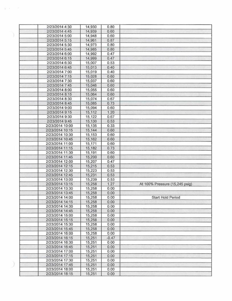
2/23/2014 4:30 14,930 0.80 2/23/2014 4:45 14,939 0.60 2/23/2014 5:00 14,948 0.60 2/23/2014 5:15 14,961 0.87 2/23/2014 5:30 14,973 0.80 2/23/2014 5:45 14,985 0.80 2/23/2014 6:00 14,992 0.47 2/23/2014 6:15 14,999 0.47 2/23/2014 6:30 15,007 0.53 2/23/2014 6:45 15,013 0.40 2/23/2014 7:00 15,019 0.40 2/23/2014 7:15 15,028 0.60 2/23/2014 7:30 15,037 0.60 2/23/2014 7:45 15,046 0.60 2/23/2014 8:00 15,055 0.60 2/23/2014 8:15 15,064 0.60 2/23/2014 8:30 15,074 0.67 2/23/2014 8:45 15,085 0.73 2/23/2014 9:00 15,094 0.60 2/23/2014 9:15 15,112 1.20 2/23/2014 9:30 15,122 0.67 2/23/2014 9:45 15,130 0.53
2/23/2014 10:00 15,135 0.33 2/23/2014 10:15 15,144 0.60 2/23/2014 10:30 15,153 0.60 2/23/2014 10:45 15,162 0.60 2/23/2014 11:00 15,171 0.60 2/23/2014 11:16 15,182 0.73 2/23/2014 11:30 15,191 0.60 2/23/2014 11:45 15,200 0.60 2/23/2014 12:00 15,207 0.47 2/23/2014 12:15 15,215 0.53 2/23/2014 12:30 15,223 0.53 2/23/2014 12:45 15,231 0.53 2/23/2014 13:00 15,239 0.53 2/23/2014 13:15 15,258 1.27 At 100% Pressure (15,245 psig) 2/23/2014 13:30 15,258 0.00 2/23/2014 13:45 15,258 0.00 2/23/2014 14:00 15,258 0.00 Start Hold Period 2/23/2014 14:15 15,258 0.00 2/23/2014 14:30 15,258 0.00 2/23/2014 14:45 15,258 0.00 2/23/2014 15:00 15,258 0.00 2/23/2014 15:15 15,258 0.00 2/23/2014 15:30 15,258 0.00 2/23/2014 15:45 15,258 0.00 2/23/2014 16:00 15,258 0.00 2/23/2014 16:15 15,251 -0.47 2/23/2014 16:30 15,251 0.00 2/23/2014 16:45 15,251 0.00 2/23/2014 17:00 15,251 0.00 2/23/2014 17:15 15,251 0.00 2/23/2014 17:30 15,251 0.00 2/23/2014 17:45 15,251 0.00 2/23/2014 18:00 15,251 0.00 2/23/2014 18:15 15,251 0.00

2/23/2014 18:30 15,251 0.00 2/23/2014 18:45 15,251 0.00 2/23/2014 19:00 15,251 0.00 2/23/2014 19:15 15,251 0.00 2/23/2014 19:30 15,251 0.00 2/23/2014 19:45 15,251 0.00 2/23/2014 20:00 15,251 0.00 2/23/2014 20:15 15,251 0.00 2/23/2014 20:30 15,251 0.00 2/23/2014 20:45 15,251 0.00 2/23/2014 21:00 15,251 0.00 2/23/2014 21:15 15,251 0.00 2/23/2014 21:30 15,251 0.00 2/23/2014 21:45 15,251 0.00 2/23/2014 22:00 15.251 0.00 2/23/2014 22:15 15,251 0.00 2/23/2014 22:30 15,251 0.00 2/23/2014 22:45 15,251 0.00 2/23/2014 23:00 15,251 0.00 2/23/2014 23:15 15,251 0.00 2/23/2014 23:30 15,251 0.00 2/23/2014 23:45 15,251 0.00 2/24/2014 0:00 15,251 0.00 2/24/2014 0:15 15,251 0.00 2/24/2014 0:30 15,251 0.00 Hold Complete 2/24/2014 0:45 14,900 -23.40 Begin Depressurization 2/24/2014 1:00 14,352 -36.53 2/24/2014 1:15 13,300 -70.13 2/24/2014 1:30 12,089 -80.73 2/24/2014 1:45 10,921 -77.87 2/24/2014 2:00 9,913 -67.20 2/24/2014 2:15 8,913 -66.67 2/24/2014 2:30 8,075 -55.87 2/24/2014 2:45 7,158 -61.13 2/24/2014 3:00 6,363 -53.00 2/24/2014 3:15 5.454 -60.60 2/24/2014 3:30 4.786 -44.53 2/24/2014 3:45 4,155 -42.07 2/24/2014 4:00 3,575 -38.67 2/24/2014 4:15 2,973 -40.13 2/24/2014 4:30 2,487 -32.40 2/24/2014 4:45 2,002 -32.33 2/24/2014 5:00 1,603 -26.60 2/24/2014 5:15 1,204 -26.60 2/24/2014 5:30 904 -20.00 2/24/2014 5:45 645 -17.27 2/24/2014 6:00 464 -12.07 2/24/2014 6:15 261 -13.53 2/24/2014 6:30 160 -6.73 2/24/2014 6:45 80 -5.33 2/24/2014 7:00 0 -5.33 2/24/2014 7:15 0 0.00 2/24/2014 7:30 0.00 2/24/2014 7:45 0.00 2/24/2014 8:00 0.00 2/24/2014 8:15 0.00

2/24/2014 8:30 0.00

JKS-01 Pressure 15,260
15,258
15,256
15,254
15,252
15,250
15,248
15,246
Pressure
~ i — i — i — i — i — r
rvO ,vO rvO d P # S S S # CN^ ^ <$> 0 $ C $ 0 $ S CS^
^ 4? A? A® ^ J> ^ rnP S> sP ^ ^ ^ ^ ^ ^ ^ ^ ^ ^ ^ ^ ^
rsr <$r *Nr &r rSr rSr ^ ^ ^ .JP
i r # i r i r # # # i r # ^ # ^N^V T\T ^\^ ^\^ ^\^ iT i r ^ ^