United States army aircraft production facts
116
UC-NRLF G _ 714 27fl M46 United States Army Aircraft Production Facts COMPILED AT THE REQUEST OF THE ASSISTANT SECRE TARY OF WAR By COL. G. W. MIXTER, A. S., A. P. AND LIEUT. H. H. EMMONS, U. S. N. R. F. Of the Bureau of Aircraft Production JANUARY, 1919 HCTORY CREED " To foster individual talent, imagination, and initiative, to couple with this a high degree of cooperation, and to subject these to a not too minute direction; the whole vitalized by a supreme purpose which serves as the magic key to unlock the upper strata of the energies of men" Major General Sqttier. WASHINGTON GOVERNMENT PRINTING OFFICE 1919
Transcript of United States army aircraft production facts

UC-NRLF
G _714 27fl
M46 United States Army
Aircraft ProductionFacts
COMPILED AT THE REQUEST OF THE ASSISTANT SECRE TARY OF WAR
By
COL. G. W. MIXTER, A. S., A. P.
AND
LIEUT. H. H. EMMONS, U. S. N. R. F.
Of the Bureau of Aircraft Production
JANUARY, 1919
HCTORY CREED" To foster individual talent, imagination, and initiative,
to couple with this a high degree of cooperation, and to
subject these to a not too minute direction; the whole
vitalized by a supreme purpose which serves as the magic
key to unlock the upper strata of the energies of men"
Major General Sqttier.
WASHINGTONGOVERNMENT PRINTING OFFICE
1919


United States Army
Aircraft Production
Facts
COMPILED AT THE REQUEST OF THE ASSISTANT SECRETARY OF WAR
By
COL. G. W. MIXTER, A. S., A. P.
AND
LIEUT. H. H. EMMONS, U. S. N. R. F.
Of the Bureau of Aircraft Production
JANUARY, 1919
VICTORY CREED" To foster individual talent, imagination, and initiative,
to couple with this a high degree of cooperation, and to
subject these to a not too minute direction; the whole
vitalized by a supreme purpose which serves as the magic
key to unlock the upper strata of the energies of men."
Major General Squier.
WASHINGTONGOVERNMENT PRINTING OFFICE
1919

r

CONTENTS.
Pa-se:
INTRODUCTION
Aviation in the United States
Industrial conditions
Early programs 7
Organization of the Equipment Division _
AVIATION ENGINES
Elementary training 11
Advanced training
Rotary engine
Fixed cylinder engine 14
Combat engines 15
Designing the Liberty engine 16
Production of Liberty engines 22
Other combat engines Rolls-Royce ; Bugatti ; Hispano-Suiza 27
Tables of engine production 29
AIRPLANES 32
Lumber supply * 34
Fabric 37
Dope *. 39
Engineering resources : 41
Manufacturing facilities 43
Training planes 44
Service planes DH-4 46
Other planes Spad, Bristol, Lepere 48
New designs of service planes 50
Night bombers Handley Page 51
Production review 54
Planes at front Nov. 11 57
AIRCRAFT MACHINE GUNS 59
AIRPLANE BOMBS 67
AEKIAL PYROTECHNICS 69
PHOTOGRAPHIC EQUIPMENT 72
AVIATORS' CLOTHING 79
OXYGEN FOR THE AVIATOR 82
AIRPLANE RADIO EQUIPMENT 86
Telegraphy 86
Telephony 89
Production ; 91
THE SENTINEL OF THE SKY.
Development of the kite balloon 93
The balloon cloth problem 98
Rubberized balloon fabric 99
Windlasses 100
Cable J 101
Helium gas 103
Parachutes 104
Tables of balloon production -VNT*-*-*-* 106
M65339 3

INTRODUCTION.
The Wright brothers, on December 17, 1903, at Kitty Hawk, N. C.,
made man's first successful sustained and directed flight in a heavier-
than-air machine, driven by a gas engine. Wilbur Wright flew 852
feet in 59 seconds, and his four-cylinder gas engine generated 12
horsepower. Thus started the development of the enormous air
activity to be later used in warfare.
To fully understand the position of the United States in aeronau-
tics at the time of our declaration of war, one must realize how verylittle of the development had been carried on in this country; how
relatively lacking we were in knowledge of aeronautics, and how
completely and* absolutely we lacked knowledge of the equipment of
military airplanes.
The Army had done some flying at San Diego, using the flyingfield on North Island, which had been made available by the gen-
erosity of the Coronado Beach Co., who loaned the land to the Gov-
ernment, as no funds were available at that time for leasing propertyfor flying fields.
The Air Service had had a struggling and meager existence, work-
ing with the old pusher type of planes, until, in 1914, an appropria-tion of $250,000 was made available for the purchase of airplanesand their equipment.About this time five officers were sent to the Massachusetts Insti-
tute of Technology for a special course in aeronautics. These menconstituted the entire technically trained personnel of the Air Service
of the United States Army when war was declared in Europe in
August, 1914. The total personnel, both military and civilian, num-bered 194 men, with a minimum of equipment. At the time of sign-
ing the armistice the records showed a total of 195,024 men, to whomhad been delivered during the war 16,952 airplanes.
The creation of this personnel, and their equipment, in all its in-
finite detail, was one of the great problems of the war. This pam-phlet presents the story of the production of aircraft in nontechnical
language as an aid to a better understanding of the past and future
industrial problems of the Air Service.

AIRCBAFT PRODUCTION FACTS. 5
Air Service, U. S. A., Personnel and Planes, in 1914, 1917, and 1918.

6 AIRCRAFT PRODUCTION FACTS.
pie planes and engines of limited capacity in a small way. These
operations had not passed the experimental stage and had not
developed with rapidity, because there existed neither commercial
demand nor adequate Government support. These planes and
engines were not at all suitable for fighting purposes, although
some of them were later adapted and used for training aviators.
The 59 planes which were delivered during the eight years prior
to 1917 had been supplied by four different makers, the largest
number ordered from any one maker being 22. 1
Fourth. There was no definite understanding as to how much
aircraft equipment would be required for the use of the Army or
Navy, and therefore no program to work to.
The initial step to meet the situation was taken in April, 1917, when
Gen. Squier asked that experts in aeronautical matters be dispatched
to the United States from England, France, and Italy. Shortly after
this over 100 expert American mechanics were sent overseas to gain
experience in European engine and airplane plants. On June 17,
1917, a special technical mission, headed by Col. Raynal C. Boiling,
sailed for Europe with instructions to investigate and recommend
types of airplane and other aeronautical equipment for production in
the United States.
Such was the situation in June, 1917, when the tremendous de-
mands for American-built planes were first laid down. No American-
built plane had ever fought over the battlefields of Europe. The
development of planes had gone on so rapidly that the machine
which was best to-day might to-morrow be relegated to the scrap pile.
We will not enter here into the causes, some military, some civil, of
this utter unpreparedness, but the outbreak of the war found the
United States with but a handful of fliers and very few training
planes. There was no aviation industry in this country, and the
number of professional men trained as aeronautical engineers and
designers was so small as to be practically negligible. In this respect
the problem of developing the air program was unique. The United
States had built ships before, had manufactured clothing, guns, muni-
tions, built cantonments, etc., and had a splendid body of men trained
in these professions and employments, but outside of a few men there
!The general condition of the industry in the United States is further reflected bythe status of Government orders on May 12, 1917. At that time the Government hadoutstanding orders for a total of 334 flying machines, including both airplanes for the
Army and flying boats for the Navy. These orders were placed with 16 different manu-facturers, six of whom had probably never built more than 10 machines apiece. Theseorders called for 10 distinct types of 32 different designs. The largest order placedwith any one manufacturer was one for 126 machines of varied design given to the
Curtiss Airplane & Motor Corporation. Most of the machines covered by these orders
were never delivered, as the manufacturers generally requested release from their
contracts.

AIRCRAFT PRODUCTION FACTS. 7
was no one in the United States with experience in the design or
building of even training planes.After the United States actually entered the war, the pressure
from our allies and a sudden realization of our real situation led
Congress to grant large sums of money for aeronautics. The act
of May 12, 1917, appropriated $10,800,000; the act of June 15, 1917,
$43,450,000 ;and finally the appropriation of $640,000,000 was passed.
The latter was the largest appropriation ever made by Congress for
one specific purpose; it was put through the House of Representa-tives Military Affairs Committee in two sittings, the House itself in
one, the Senate Military Affairs Committee in 45 minutes, and the
Senate itself a week later, becoming -a law on July 24, 1917, three
months and a half after the outbreak of war.
The first indicated realization of the magnitude of the problem
facing the United States is reflected in the program recommended
by the Joint Army and Navy Technical Board about June 1, 1917.
This called for practically 22,000 airplanes, to be completed by July
1, 1918, of which 10,000 were to be for training purposes, and 12,000for fighting in France. 1
With the knowledge then at hand even these figures did not conveya correct idea of the production required to meet this program. Theinfinite complications of fully equipped battle planes were little under-
stood, neither was the fact fully realized that for each 100 airplanesan equivalent of 80 additional airplanes must be provided in spare
parts. In fact, the program laid down in June, 1917, involved the
production, not of 22,000 airplanes by July 1, 1918, but rather the
equivalent of 40,000 airplanes. A consideration of these enormous
requirements in comparison with the available industrial facilities of
the country will convey some idea of the magnitude of the task pre-
sented to the officers charged with the execution of the air program.To understand how the situation was handled, the following sum-
mary of the vital moves made in the early days of the war should be
borne in mind.
1. In April, 1917, Gen. Squier asked that aeronautical expertsbe sent to the United States from overseas.
2. In May mechanics were sent overseas to learn the details of
foreign practice.
3. The design of the Liberty motor was started in the last
days of May.
1 The entire production of the country for the previous 12 months, consisting princi-
pally of training planes and training boats for foreign Governments, was less than 800.In January and February, 1017, it had been thought feasible to build 1,000 planes in a
year ; in March an annual production of 2,500 planes was discussed ;in April it was
proposed to build 3,700 planes in 12 months. These figures indicate the rapidity withwhich ideas changed during this period.

8 AIRCRAFT PRODUCTION FACTS.
4. The Boiling mission sailed for Europe June, 1917.
r>. In August the Signal Corps organized:The Equipment Division for the design and production of
aeronautical material, including balloons.
The Construction Division for the preparation and con-
struction of training fields, etc.
The Air Division for the training of aviators.
6. In August orders were placed in France for over 5,000
planes to cover the American Expeditionary Forces' require-
ments up to July 1, 1918.
The first problem was the choice of type and design of aeronautical
equipment which should be adopted for manufacture in this country.Time was not available for the experimentation required to develop
purely American planes. It was also obvious that an intelligent de-
cision regarding types of European planes or engines which should
be put into production could not well be made anywhere but in
Europe. It was hopeless to attempt to weigh the arguments of dif-
ferent competing representatives of foreign companies.1 The art
was progressing so fast that studies of types of equipment wouldhave to be made on the front by experts aided by the best counsel
obtainable from each of the allied countries. The Boiling commission
was, therefore, organized in May, 1917, to proceed to Europe pri-
marily for the purpose of investigating aeronautical conditions and
requirements among our allies, and of advising us as to the types of
planes, engines, and other equipment which we should prepare to
manufacture. The commission was instructed to investigate both in-
dustrial and military conditions with particular emphasis on the
rapid development of requirements at the front. Being at such a
distance from the scene of operations, it was clearly essential that
developments should be anticipated whenever possible so that by the
1 Agents for the various European manufacturers swarmed through the offices of the
Aircraft Board. Each of them could produce unanswerable demonstrations of the superiorexcellence of his article, but it soon developed that practically all of them called for
the payment of very considerable royalties. The following tabulation, compiled byCol. S. D. Waldon, illustrates some of these proposals :
Royalty asked
per
April 10, 1917: 1,000 units.
Short seaplanes $675, 000
Sopwith planes 500, 000
Clerget engines 700, 000Sunbeam (including cost of engine and royalty)
200-horsepower engines 7, 000, 000
300-horsepower engines 8, 000, 000
Apr. 14, 1917 : Caproni rights 2, 000, 000
May 8, 1917 : Gnome engines 1, 215. 000
Clerget 821, 250
May 19, 1917 : Gnome 100-horsepower engines 500, 000Le Rhone, 80-horsepcwer engines 1, 375, 000
May 24, 1917 : Handley Page rights 200, 000June 2, 1917 : Le Rhone engines 600, 000
AIRCRAFT PRODUCTION FACTS. 9
time material could be put into production, transported overseas, anddelivered to the front it would still be of a type which would be use-
ful in service and not obsolete by reason of progress made meanwhile.
The commission sailed on June 17, 1917, under the leadership ofCol. R. C. Boiling. It comprised two members from the Army, twofrom the Navy, and two from civilian life. The- Army memberswere Captains Clark and Gorrell, both able aeronautical engineers,who had been in charge of the very small airplane engineering organi-zation which existed at the beginning of the war as a part of the
Signal Corps. The Navy members were Commander Westervelt and
Lieut. Childs. The civilian members were Howard Marmon, one of
the leading motor experts in the automobile industry and a highlytrained all-around engineer, and Herbert Hughes, who was an auto-
mobile engineer associated with the Packard Motor Car Co.
The Equipment Division of the Signal Corps, charged with the
design and production of all equipment for the Air Service was
organized with the following initial personnel :
Edward A. Deeds, an engineer and successful manufacturer of
Dayton, Ohio, chief of the division.
Harold H. Emmons, an attorney and manufacturer of Detroit,chief of engine production.Leonard S. Horner, of the Acme Wire Co. of New Haven, chief
of production of instruments and ordnance.
George W. Mixter, vice president and manager of manufactureof Deere & Co., who was placed in charge of inspection.
R. L. Montgomery, a banker of experience in Philadelphiaand New York.
Harry L. Shepler, production manager of the Willys-Over-
land Co., chief of plane production.Melville W. Thompson, an expert accountant and valuator, of
New York City.
J. G. Vincent, vice president Packard Motor Car Co., chief of
engine design.
Sidney D. Waldon, formerly vice president and general
manager of the Packard Motor Car Co.; later associated with
the Cadillac Motor Car Co.;and later in an independent consult-
ing capacity as an automobile expert.
All were commissioned in the Army except Lieut. Emmons, whohad for 12 years been an officer in the Naval Reserve and who wasdetailed by the Navy Department to this work.
In January, 1918, W. C. Potter, of the Guggenheim interests,
became Chief of the Equipment Division. When the Air Service was
separated from the Signal Corps in May, 1918, John D. Ryan, of the
Anaconda Copper Co., was appointed Director of Aircraft Produc-

10 AIKCKAFT PKODUCTION FACTS.
tion and later an Assistant Secretary of War and Director of Air
Service. Mr. Potter continued as first Assistant Director of the
Bureau of Aircraft Production A. A. Landon, of the American
Radiator Co., assisting on production, and C. W. Nash, of the NashMotors Co., in engineering.
Such were the. conditions, the problems presented, and the initial.
steps taken to meet the situation. The detail of the production de-
velopment on each class of equipment is presented in the following
pages, but it is worthy of note here that at the time of the signingof the armistice there had been produced in the United States 612
kite balloons, 11,754 airplanes, and more than 30,000 aviation enginesof more than 7,800,000 horsepower.

AVIATION ENGINES.
Extensive preparation is required for quantity production of
engines according to American methods of manufacture;this prepa-
ration takes time and involves many varied and intricate engineer-
ing problems. These facts, which were recognized from the first,
made it essential to select the types and sizes of engines at the earliest
possible moment. It was necessary to await information from Europebefore final decisions could be reached regarding planes, armament,and equipment, but the selection of engines could be made more
promptly. The general problem was to select engines which would
be of sufficient capacity and range to cover all requirements, which
would comprise the smallest possible number of different types, and
which would lend themselves to our methods of manufacture.
Aeronautical engines may be classified under two general heads
as follows:
Engines required for training purposes.
Engines required for combat purposes.
It was necessary to proceed with the utmost expedition in the pro-duction of both types of equipment, but with the lack of knowledgeas to requirements on the front and with the need for equipment for
the immediate training of aviators, special attention was demanded
by the training program. This, according to the best information,
required engines for elementary or primary training and engines for
advanced training. It was early determined that the number of
types of planes and engines to be used for training purposes should
be as limited as possible. Full consideration of the subject andconsultations with such representatives of our allies as were available
in this country developed a general desire to standardize, if possible,
on one, or at the most two, types of equipment for each class of train-
ing. This policy would avoid delay both in training the aviator and
in preparing him for his actual combat work and also the confusion
inseparable from a large number of different types of equipment.
ELEMENTARY TRAINING ENGINES.
The Curtiss JN-4 plane equipped with the Curtiss OX 90-horse-
power engine were the most available plane and engine in this country11
AIRCRAFT PRODUCTION FACTS.
for primary training purposes. The capacity of the Curtiss plantwas insufficient to produce the required number of these planes andengines. The production of planes at the Buffalo plant could be
largely and rapidly increased, but the capacity for producing enginesof the OX type, which were made only at Hammondsport, could not
keep pace with the planes and at the same time complete existingorders which it had previously accepted from the English and Cana-dian aviation authorities. Therefore an additional contract for 5,000of these engines was placed with the Willys-Morrow company at
Elmira, K Y.
Meanwhile the Air Division was developing its requirements veryrapidly. No training equipment was in existence, but many trainingfields were being prepared and plans were being pushed forward
calling for the early training of many thousand student aviators.
The great difficulty connected with providing training planes and
engines as fast as wanted was the fact that the program laid downfor the establishment of new aviation schools and fields called for a
very heavy initial equipment, followed by a comparatively low rate
of wastage. In other words, during the first six to eight months,while many large schools would be going into operation, the curveof requirements increased rapidly, reaching its peak about January 1,
1918. Thereafter, with schools and fields completed and equipped, a
modest production schedule would take care of their requirementsfor upkeep and wastage.
It was therefore essential to procure immediately an additional
source of supply for elementary training equipment. The StandardAero Corporation had, for approximately a year, been developing its
Standard J plane and was prepared to proceed with its production.The Hall-Scott Co. had been, with the possible exception of the Cur-
tiss Co., the largest producer of aviation engines in the country priorto midsummer of 1917. It had then actually in production a four-
cylinder engine which, while it was known to have a certain amountof vibration common to any four-cylinder engine, was regarded as a
rugged and reliable engine. It had been installed in planes made bythe Standard Aero Corporation, the Aeromarine Co., and the Dayton-
Wright Co. The Joint Army and Navy Technical Board therefore
recommended, as the alternate elementary training equipment, the
Standard J plane and the Hall-Scott four-cylinder ATA engine.
Contracts were at once placed with the Hall-Scott Co. for 1,250 of
these engines, and with the Nordyke & Marmon Co. for 1.000 of them;
arrangements were also made with the Hall-Scott Co. for assistance
in furnishing drawings, tools, etc., to the other manufacturers.

AIRCRAFT PKODUCTION FACTS. 13
ADVANCED TRAINING ENGINES.
Advanced training called for two types of engine :
First. A rotary engine which would train the student for
work in the small speedy fighting planes.
Second. A fixed cylinder engine having upward of 100 horse-
power.
ROTARY ENGINE.
To meet the rotary engine requirements there were available the
Gnome 110-horsepower engine, which was being built in small quanti-ties by the General Vehicle Co. for delivery on a foreign order, the
150-horsepower Gnome engine, recommended as part of our combat
program, and the Le Rhone 80-horsepower engine. The two latter
engines had been developed and used in France, but neither had been
built at all in this country. The first recommendations received fromour aviation representatives in Europe advised the production of
5,000 Gnome 150-horsepower and 2,500 Le Rhone 80-horsepower
engines.
The production of 5,000 large Gnome engines was entirely beyondthe capacity of the General Vehicle Co., and therefore negotiationswere entered into with the General Motors Co. to take this contract.
After many weeks of negotiations the General Motors Co. and the
General Vehicle Co. agreed to combine, the former bringing to the
work its vast resources and numerous factories, while the latter con-
tributed its skilled knowledge and experience in the production of
rotary engines. Just at this point cable instructions were received
recommending that preparations to produce this engine be discon-
tinued. This instruction was followed and thereafter the General
Vehicle Co. was called upon to produce as many of the 110-horse-
power Gnome engines as it could with its existing equipment.Meanwhile the Union Switch & Signal Co., of Swissvale, Pa. (ona
of the Westinghouse Airbrake chain of factories), had been induced
to undertake the manufacture of 2,500 Le Rhone 80-horsepower en-
gines. A sample engine was received from Europe during the first
week in September. It, however, was not accompanied with com-
plete or reliable drawings, specifications, and metallurgical instruc-
tions. For example, the French specifications called for a crank shaft
made from mild steel. It was apparent that this was incorrect, and
in fact it was necessary to analyze every piece of the engine to de-
termine the proper material. The drawings had to be carefully
checked and corrected, a proceeding which required several months
of intensive work on the part of a large corps of draftsmen and

14 AIRCKATT PRODUCTION TACTS.
engineers. Finally it was necessary to prepare detail drawings ;this
was done under the direction of Lieut. Col. E. J. Hall and Lieut. F.
M. Hawley. During this time the Union Switch & Signal Co. hadbeen procuring its machinery, tools, and equipment. The services of
M. Georges Guillot, the French engineer of the Gnome-Le Rhone
factories, were procured from France, and he was assigned to the
plant of the Union Switch & Signal Co. This company turned out
its first production engines in May, 1918, and has now substantially
completed its contract. The engines which it has produced have been
certified by M. Guillot as being the best constructed rotary engineswhich have ever been built.
f
FIXED CYLINDER ENGINE.
A fixed cylinder type of engine suitable for advanced trainingwas already being built in this country for France. This was the
150-horsepower Hispano-Suiza, During the early years of the warit had been one of the most popular engines for both. combat and
training in England and its dependability had been thoroughly
proved. Early in 1916, this engine had been brought to this countryand after 13 months of work, the Wright-Martin Aircraft Corpora-tion had actually begun to produce it. By 1917, combat planes were
using more powerful engines and the service demand for the His-
pano-150 decreased. This engine, however, could be readily installed
in the Curtiss JN type of plane, making a combination which became
most useful for instruction in bombing, photography, etc.
Contracts for several thousand of these engines were placed with
the Wright-Martin Aircraft Corporation and provision was madefor increasing its manufacturing facilities to take care of this pro-duction.
There had been manufactured in this country a few engines of
other types, such as the Curtiss OXX and Y type engines, a few of
which were used by the Navy, but which were not regarded as first-
class engines by either the British or the Signal Corps. Also the
Sturtevant Co., had built a small number of 135-horsepower enginesand the Thomas Brothers at Ithaca had built a few engines of the
Sturtevant type which they claimed to be an improved engine having
substantially the same horsepower. Both of these engines were con-
sidered to be too low in horsepower to endure for any considerable
period of manufacture; they were also too heavy per horsepower.This opinion, held in the United States, was confirmed on July 11,
1917, by cable No. 37, paragraph 7, signed"Pershing," which said :
"We consider no need whatever Thomas-Sturtevant 8 cylinder.''

AIRCRAFT PRODUCTION FACTS. 15
The American training program was, therefore, built around the
following engines: Curtiss OX-5, Hall-Scott ATA, Hispano-Suiza
150-horsepower, fixed cylinder engines and Gnome and Le Rhone.ro-
taries. The quality of this training equipment may be gauged some-
what by the results obtained from it on the United States trainingfields. The statistics show that from September 1, 1917, to December
19, 1918, 13,250 cadets and 9,075 students were sent to 27 fields for
advanced training. They flew 888,405 hours and suffered 304 fa-
talities, or an average of 2,922.38 flying hours per fatality. At one
field 19,484 flying hours, at another 20,269 flying hours, and at an-
other 30,982 flying hours resulted in but one casualty each. The best
unofficial figures obtainable show that the British averaged one fa-
tality for each 1,000 flying hours, the French one for each 900 flying
hours, and the Italians one for each 700 flying hours. These figures,
however, probably reflect the result of more intense advanced train-
ing than do the American figures.
On November 29, 1918, there had been produced and delivered
into service 16,286 training engines.
COMBAT ENGINES.
During the time that the production of engines for training was
getting under way, careful thought was given to the possibilities of
producing combat engines quickly in the United States. An analysisof the situation in May 1917, reflects the following facts :
First. The Joint Army and Navy Technical Board, togetherwith the Aircraft Board, were about to recommend a programcalling for the production of 12,000 combat planes for delivery in
France by July, 1918.
Second. Much time would necessarily elapse before the BoilingCommission could make its report and .send back sample engineswith drawings and other data required by American manufac-
turers. Experience in this country with the Gnome and Hispano-Suiza engines also indicated that foreign drawings and specifica-
tions would have to be completely revised and remade before any
production could start here. This conviction was subsequentlyverified by the experience with the Le Rhone and Bugatti engines.
Third. Engines of increasing horsepower were being demanced
at the front;this indicated the early abandonment of sizes md
types of engines previously in favor. In fact, up to May, 1*17,
there was not among the Allies any well-proved engine (with the
possible exception of the Rolls-Royce engine, see page 27) of a
horsepower sufficiently large to insure its popularity and suit-

16 AIRCRAFT PRODUCTION FACTS.
ability for two years.1 American experience with large-scale pro-
duction of automobile engines had shown that two years would. be required to tool up for and to obtain a year's output of a given
engine.
Fourth. At that time England was manufacturing or ex-
perimenting with 37 different kinds of engines and France with
46. It seemed wise, if possible, for the United States to avoid a
similar situation, with its exacting requirements for innumerable
repair parts a situation which would be complicated still further
by long distance from the scene of war.
Fifth. There were in the United States extensive facilities for
the production of the simpler forms of internal-combustion en-
gine, such as those used in automobiles. American engineers andmanufacturers had had wide experience in designing such enginesand in producing them in quantity. American engineering talent
and ingenuity and knowledge of design was at least equal to that
abroad.
Sixth. It was apparent that prompt action was necessary to
meet the enormous requirements for engines and spares de-
manded by the contemplated program. It was also clear that these
requirements could not be met unless the automobile-engine in-
dustry could be mobilized for that purpose; furthermore, even
with the talented organizations and experience of this industry,there was little chance of completing the task unless their efforts
could be concentrated on one type of standardized engine designed
especially to suit American quantity-production methods.
DESIGNING THE LIBERTY ENGINE.
With the foregoing facts in mind and after many preliminary
investigations, Col. Deeds came to the conclusion that it was es-
sential for the United States to concentrate its energies upon the
smallest possible number of types of engines and to give special at-
tention to equipment which could be manufactured in quantity, andwhich would be least affected by the rapid advances in the art.
He considered it entirely possible to design and build an enginesuitable for war purposes and adapted to American ideas of quan-
tity production in less time than the Boiling Commission could com-
plete its investigations and negotiations and send us drawings and
molels of European types that in all probability would be wholly
1 T\is point is further illustrated by the following : In May, 1917, every foreign repre-sentatve with aeronautical experience, in Washington, agreed that an 8-cylinder, 225-
horsejower engine was the right one for the United States to develop for the spring of1918. Inside of 90 days, it was equally clear and all were equally unanimous that a 12-
cylinder, 330-horsepo\vr engine was required.

AIKCRAFT PKODUCTION FACTS. 17
unsuited to our production methods. He believed that the United
States should concentrate its greatest effort on a type of aircraft
engine which could be made in powers sufficiently high to assure
continued usefulness for a term of years and. which would possess
the maximum degree of interchangeability between similar parts.
Col. Deeds proposed this plan immediately to his associate, Col.
S. D. Waldon, who, after giving it careful consideration, agreed en-
tirely with the plan. A few days later J. G. Vincent, of the Packard
Motor Car Co., arrived in Washington and proposed substantially
the same idea, which had been developed as the result of his ex-
perience with aircraft engines, and which had been crystallized byconferences which he had held in Detroit with the French and Eng-lish commissions which were then touting the United States.
As subsequent investigation proceeded this conclusion received the
unanimous support of both the American and European authorities
and its wisdom has been absolutely demonstrated by the results
which have been attained.
The line of engines finally decided upon was of 4, 6, 8, and 12
cylinders, respectively, all having a bore of 5 inches and a stroke of
7 inches. The 8-cylinder engine rated at 225 horsepower was the one
believed to anticipate the requirements for power as of the springof 1918, and the 12-cylinder rated at 330 horsepower was considered
as anticipating the development through 1919 and 1920.
Col. Deeds, Col. Waldon, and Messrs. E. J. Hall and J. G. Vin-
cent 1 met at Col. Deeds's apartment in the New Willard Hotel in
Washington and considered in a general way the requirements which
this American line of engines must meet. It was determined that
they should be built around a 5 by 7 inch individual steel cylinder
with aluminum piston, forked rods, and direct-drive propeller, and
1 The following notes about Messrs. Vincent and Hall showing their previous ex-
perience and training are of general interest :
J. G. Vincent, of the engineering staff of the Packard Motor Car Co., had been engagedin research work for approximately two years, developing several types of 12-cylinder
aviation engines, ranging from 125 to 225 horsepower, which, however, were not suitable
for military purposes because of their weight per horsepower. This work had resulted
in the acquirement of a large amount of data and information which was invaluable in
the design of such an engine as the one proposed, and also had resulted In the upbuildingof an efficient experimental organization. He had also had wide experience in designinginternal-combustion engines for quantity production.
E. J. Hall, of the Hall-Scott Motor Car Co., for eight years had been developing and
latterly producing several types of aeronautical engines, which had been delivered for
service to the Governments of Russia, Norway, China, Japan, Australia, Canada, and
England. He had also completed and tested a 12-cylinder engine of 300 horsepower,
which, however, was of too great weight per horsepower to be suitable for military pur-
poses. He had thus acquired a wide general experience and a knowledge of quantity
production ; he also possessed a fund of information covering the proper sizes andmaterials for engine parts, and the proper methods of testing engines. All of this informa-
tion and experience proved to be of invaluable assistance not only in designing the newengine, but in determining its essential metallurgical and manufacturing specifications.
10654819 2

18 AIRCRAFT PRODUCTION FACTS.
that nothing experimental or untried should be used. The size 5 by7 inches was adopted because the Curtiss Aeroplane & Motor Cor-
poration and the Hall-Scott Motor Car Co. had had experiencewith engines of this size, and also because Maj. Tulasne, of the
French mission, ascertained by cable that the new Lorraine-Dietrich,then the most promising French experimental engine, approximatedthat size.
Messrs. Vincent and Hall set to work on May 29 to combine their
knowledge and information, and within two or three days they hadoutlined the important characteristics of design of the Liberty en-
gine. These preliminary layouts were submitted to the Aircraft
Production Board and the Joint Army and Navy Technical Board,who approved the design and on June 4 authorized the construction
of five each of the 8 and 12 cylinder sizes.
Detail and manufacturing drawings were begun immediately ;this
work was done partly by the staff of the Packard Motor Car Co.,
under Mr. O. E. Hunt, and partly by an organization recruited fromvarious automobile factories and working at the Bureau of Stand-
ards under Mr. Vincent. Parts for 10 engines were at once started
through the tool rooms and experimental shops of various motor car
companies. This work centered in the plant of the Packard Motor
Car Co., which most cheerfully'and patriotically gave to this workits entire energies and wonderful facilities.
Every feature in the design of these engines was based on thor-
oughly proven internal-combustion engine practice. The followingwere some of the features incorporated :
Cylinders. The design of the cylinders for the Liberty enginefollowed the practice used in the German Mercedes, English Rolls-
Royce, French Lorraine-Dietrich, and others, both before and duringthe war. The cylinders were made of steel inner shells surrounded
by pressed-steel water jackets. The Packard Motor Car Co., by long
experiment had developed a practical production method of welding
together the several parts of a steel cylinder.
Cam Shaft and Valve Mechanism Above Cylinder Heads. The
design of the above was based on the general arrangement of the
Mercedes and Rolls-Royce, but had been improved for automatic
lubrication without wasting oil by the Packard Motor Car Co.
Cam-shaft Drive. The cam-shaft drive was the same general typeas used on the Hall- Scott, Mercedes, Hispano-Suiza, Rolls-Royce,
Renault, Fiat, and others.
Angle Between Cylinders. In the Liberty the included angle be-
tween the cylinders is 45. This angle was adopted to save head re-
sistance, to give the crank case greater strength, and to reduce

AIRCRAFT PRODUCTION FACTS. 19
periodic vibration. This decision was based on the experience of the
Renault and Packard engines with approximately the same angle.
Electric Generator and Ignition. The Delco system of ignition,
which had been successfully used on hundreds of thousands of inter-
nal-combustion engines, was adopted, a special design being producedfor the Liberty engine to provide a reliable double ignition.
Pistons. The die-cast aluminum alloy pistons of the Liberty enginewere based upon extensive research and development work by the Hall-
Scott Co. under service conditions.
Connecting Rods. The well-known forked or straddle-type con-
necting rods as used on the De Dion and Cadillac cars, and also on the
Hispano-Suiza and other aviation engines, were adopted.Crank Shaft. The crank shaft design followed the standard prac-
tice for large-bore engines, every crank pin operating between twomain bearings as in the Mercedes, Rolls-Royce, Hall-Scott, Curtiss,and Renault engines.
Crank Case. The crank case followed the design of the Mercedes
and Hispano-Suiza, in which the crank case is a box section carryingthe shaft in bearings clamped between the top and bottom halves bymeans of long through bolts.
Lubrication. The original system of lubrication combined the fea-
tures of a dry crank case, such as in the Rolls-Royce, with pressurefeed to the main crank-shaft bearings, and scupper feed to crank-pin
bearings, as in the Hall-Scott and in some foreign engines. This was
subsequently changed to add pressure feed to crank-pin bearings, as
in the Rolls-Royee and Hispano-Suiza engines.
Propeller Hub. The propeller hub design followed that used on
such well-known engines as the Hispano-Suiza and Mercedes.
Water Pump. The conventional centrifugal type of water pumpwas adapted to the Liberty.
Carbureter. The Zenith type of carbureter was adapted for use
on the Liberty engine.
The parts for the first engine were made in various plants as
follows :
The General Aluminum & Brass Manufacturing Co., of De-
troit made the bronze-back, babbit-lined bearings.The Cadillac Motor Car Co., of Detroit, made the connecting
rods, connecting-rod upper-end bushings, connecting-rod bolts,
and rocker-arm assemblies.
The L. O. Gordon Manufacturing Co., of Muskegon, made the
cam shafts.
The Park Drop Forge Co., of Cleveland, made the crank-shaft
forgings. These forgings, completely heat treated, were pro-

20 AIRCRAFT PRODUCTION FACTS.
duced in three days; this quick work was made possible by Mr.
Hall, who furnished dies which he had on hand.
The crank shafts were machined at the Packard factory.The Hall-Scott Motor Car Co., of Berkeley, Calif., made all the
bevel gears.
The Hess-Bright Manufacturing Co., of Philadelphia, madethe ball bearings.The Burd High Compression Ring Co., of Rockford, 111.,
made the piston rings.
The Aluminum Castings Co., of Cleveland, made the die-cast
alloy pistons, and machined them up to grinding.The Rich Tool Co., of Chicago, made the valves.
The Gibson Co., of Muskegon, made the springs.
The Packard Co. made all the patterns, and the aluminum
castings were made by the General Aluminum & Brass Manu-
facturing Co.
The Packard Co. used many of its own dies in order to speedily
obtain suitable drop forgings, and also made new dies.
The Packard Co., produced all the other parts and did the
assembling and testing.
Meanwhile the plans of the engine had been submitted to H. M.
Crane, engineer of the Simplex Motor Car Co., and of the Wright-Martin Aircraft Corporation, who had made a special study of
aviation engines in Europe, and who for upward of a year had been
working on the production of the Hispano-Suiza 150-horsepower
engine ;also to David Fergusson, chief engineer of the Pierce-Arrow
Motor Car Co., and to many of the best experts in the country on
the production of motors, including Henry M. Leland and GeorgeH. Layng, of the Cadillac Motor Car Co., and F. F. Beall and Ed-
ward Roberts, of the Packard Motor Car Co. Representatives of
many other companies, including plane and engine makers, ma-
chine tool builders, etc., were called in;these men went over the draw-
ings thoroughly and were consulted on many production features of
the engine.
From the foregoing statements it is clear that the Liberty engine
was not developed by any species of magic nor by any single indi-
vidual or company, but was a well-considered and carefully prepared
design based on much practical aviation engine experience. The
promptness with which the design was completed and the samples
built was the result of complete cooperation between all interested
parties.
This engine so designed proved in actual operation to satisfy the
controlling requirements of the highest type of aviation engine.
These requirements, roughly speaking, are as follows:

AIRCRAFT PRODUCTION FACTS. 21
(a) Maximum power and efficiency combined with minimum
weight. The average automobile motor weighs from 6 to 10 poundsper horsepower; an aviation engine should weigh not more than
2 pounds per horsepower.
(b) Ability to run at practically maximum power and speed dur-
ing a large percentage of operating time. An automobile motor,
except in racing, rarely runs at its maximum power or speed for
more than a few moments at any one period.
(c) Reasonably low consumption of fuel and oil. This is necessaryto conserve space and weight in the plane.
Very early in the Liberty engine program it became apparent that
one of the great stumbling blocks to volume production would be the
steel cylinder if it were necessary to machine it out of a solid or
partially pierced forging, as is done in making shells. Col. Deedsand Col. Waldon laid this problem before Henry Ford and the engi-
neering organization of the Ford Motor Co. and they developed a
unique method of making the cylinders out of a piece of steel tubing.One end of the tube was cut obliquely, heated, closed over, and then
expanded into the shape of the combustion chamber and with all
bosses in place on the dome. The lower end was then heated and
upset in a bulldozer until the holding-down flange had been extruded
from the barrel at the right place. By this method a production of
2,000 rough cylinders per day was reached and the final forging was
very nearly the shape desired. The development of this cylinder-
making method was one of the important contributions to the quan-
tity production of Liberty engines ;it saved much labor and millions
of pounds of scrap.
Fundamentals of the design of the Liberty engine have not been
altered from the date of its original layout, with the single excep-tion of the scupper feed system for lubricating the crank pins whichwas abandoned in favor of the full pressure feed system of lubrica-
tion. Numerous manufacturing changes in materials, limits, clear-
ances, etc., have been made to facilitate production, exactly as such
changes are made in the production of any piece of machinery. Astime went on it became necessary to increase the horsepower of the
12-cylinder engine from 330 to 375 and later from 375 to 440. These
increases made it necessary to increase the size and strength of cer-
tain parts of the engine.
By the method outlined above the first 8-cylinder engine was de-
livered in Washington and set up at the Bureau of Standards on
July 4, 1917, and the first 12-cylinder engine was built and success-
fully passed a 50-hour endurance test by August 25, 1917.
22 AIRCRAFT PRODUCTION FACTS.
PRODUCTION OF LIBERTY ENGINES.
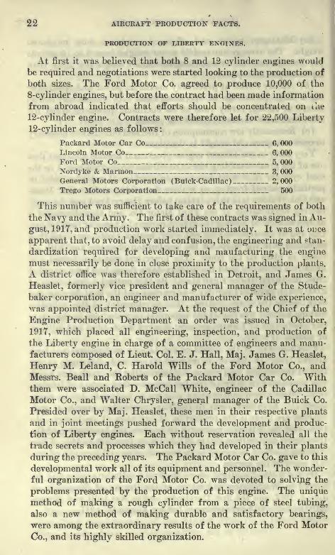
At first it was believed that both 8 and 12 cylinder engines would
be required and negotiations were started looking to the production of
both sizes. The Ford Motor Co. agreed to produce 10,000 of the
8-cylinder engines, but before the contract had been made information
from abroad indicated that efforts should be concentrated on ilie
12-cylinder engine. Contracts were therefore let for 22,500 Liberty
12-cylinder engines as follows :
Packard Motor Car Co 6, 000
Lincoln Motor Co 6, 000
Ford Motor Co 5,000
Nordyke & Marmon 3, 000
General Motors Corporation (Buick-Cadillac) 2,000
Trego Motors Corporation 500
This number was sufficient to take care of the requirements of both
the Navy and the Army. The first of these contracts was signed in Au-
gust, 1917, and production work started immediately. It was at once
apparent that, to avoid delay and confusion, the engineering and stan-
dardization required for developing and maufacturing the enginemust necessarily be done in close proximity to the production plants.
A district office was therefore established in Detroit, and James G.
Heaslet, formerly vice president and general manager of the Stude-
baker corporation, an engineer and manufacturer of wide experience,
was appointed district manager. At the request of the Chief of the
Engine Production Department an order was issued in October,
1917, which placed all engineering, inspection, and production of
the Liberty engine in charge of a committee of engineers and manu-
facturers composed of Lieut. Col. E. J. Hall, Maj. James G. Heaslet,
Henry M. Leland, C. Harold Wills of the Ford Motor Co., and
Messrs. Beall and Roberts of the Packard Motor Car Co. With,
them were associated D. McCall White, engineer of the Cadillac
Motor Co., and Walter Chrysler, general manager of the Buick Co.
Presided over by Maj. Heaslet, these men in their respective plantsand in joint meetings pushed forward the development and produc-tion of Liberty engines. Each without reservation revealed all the
trade secrets and processes which they had developed in their plants
during the preceding years. The Packard Motor Car Co. gave to this
developmental work all of its equipment and personnel. The wonder-
ful organization of the Ford Motor Co. was devoted to solving the
problems presented by the production of this engine. The unique
method of making a rough cylinder from a piece of steel tubing,
also a new method of making durable and satisfactory bearings,
were among the extraordinary results of the work of the Ford Motor
Co., and its highly skilled organization.

AIRCRAFT PRODUCTION FACTS. 23
Difficulties which ordinarily would have been well-nigh insuperable,or which at least would have prevented rapid progress, were imme-
diately encountered; for example:The existing motor-building plants had practically no ma-
chinery of sufficient size to handle the parts of the Liberty engine ;
it was therefore necessary to build and frequently to design the
machine tools for this purpose.Between 2,500 and 3,000 small jigs, tools, and fixtures are
required to produce all the parts of a Liberty engine. For large
outputs much of this equipment must be duplicated many times.
This made it necessary to requisition practically the total capacityof all the tool shops east of the Mississippi.
It soon developed that men who were able to make the com-
paratively simple automobile motors did not have the skill re-
quired to machine the parts of a Liberty engine; it therefore
became necessary to educate thousands of men and women to do
this work.
A large amount of unfriendly influence was encountered, a
considerable portion of which was doubtless pro-German. This
was manifested in the tool shops, where many of the tools madefor this work were found to be incorrect and had to be remade
before they could be used in the engine-building plants. In the
engine-building plants tools mysteriously disappeared or became
injured, cans of powder were found in the coal, fire-extinguishing
apparatus was plugged up, and numerous other treasonable acts
were committed.
As rapidly as skilled men were developed they were requisi-
tioned by nearly every department of the Government. The
draft took a great many men, and their return was either impos-
sible or was secured only after great delay.
The materials required for the engines were frequently of a
much higher grade than the corresponding materials in auto-
mobile motors and much patient work was required to secure their
production.The procurement of necessary transportation and fuel during
the winter of 1917-18 presented difficulties which at times were
almost insurmountable.
Notwithstanding the difficulties encountered, production actually
started with the delivery of 22 engines during December, 1917.
The Liberty engine as originally manufactured was of approxi-
mately 330 horsepower. Information received from overseas led to
the conclusion that a higher horsepower would be desirable. There-
fore, after about 300 of these engines were in production, the engineers

24 AIKCBAFT PKODUCTION FACTS.
stepped up the horsepower to 375. Under the additional stresses
induced, certain parts of the engine, particularly the crank shaft,
required strengthening. This was done and several hundred engineswere delivered at this horsepower. Then final and definite informa-tion arrived from abroad to the effect that if an engine of 400 horse-
power or more could be produced, the United States would lead the
combatant nations in size and power of engine during 1918 and 1919.
The engine was therefore stepped up by the engineers to 440 horse-
power. This enormous increase in power necessarily required anincrease in strength of practically all the working parts of the engine.This required changes in a very large percentage of the jigs, tools, and
equipment used in manufacture. It also required certain metallurgi-cal changes in some of the parts, which in turn involved the develop-ment of new and better methods of producing steel for them. These
changes in equipment were required in the engine plants, the parts
plants, and the forging shops ;in like manner they affected all manu-
facturers throughout the production line, including the producers of
the raw metal.
These changes were made with such speed and energy that byMay 29, 1918, one year from the date when the design of the enginewas begun, 1,243 Liberty engines had been produced and delivered
for service.
The magnitude of this accomplishment may be realized when it is
compared with the development of automobile motors. Practicallyno automobile motor of any size or importance has ever been putinto production and into service without at least one year being de-
voted to its design and development. This time was not required for
the Liberty engine, because its original design required substantially
no change and also because the best ability in the country was de-
voted without stint to its development and production.1
Much incorrect and misleading comment has been published to
the effect that many changes were made in the engine.
The changes arranged themselves in three groups :
1. Design.2. Increase of power.3. Manufacturing limits.
Design. There was but one fundamental change in designin this engine after it was laid out in May, 1917. This was to
change the oil system from the so-called scupper feed to a pres-
sure feed. Either system worked properly on the engine, but the
1 The following extract from the report of the British war cabinet for 1917 is interest-
ing in this connection :
"Experience shows that, as a rule, from the date of the con-
ception and design of an aero engine to the delivery of the first engine in series bythe manufacturer more than a year elapses."

AIRCRAFT PRODUCTION FACTS. 25
latter system is foolproof while the former is not. The latter
system was therefore substituted.
Increase of power. The changes due to increasing the horse-
power twice are covered -above. They were made solely to meet
the demands of American and foreign aviation authorities.
Manufacturing limits. As the engine was used in service and
as the manufacturing progressed, it became evident that some of
the limits might be changed, and these changes were made. This
is common practice in all manufacturing establishments. It
has always been so on automobile motors and will always be
so on any manufactured product. As manufacturing processes
are developed and as experience is gained, changes in limits are
always expected and are always made, both to expedite produc-tion and to improve quality.
During six months, from May 29 to November 29, 1918, the produc-tion of Liberty engines increased by leaps and bounds; during
October, just preceding the armistice, 150 12-cylinder engines were
being produced and delivered into service on each working day. Therecord of monthly deliveries of these engines is as follows :
December, 1917 22
January, 1918 39
February 70
March 122
April 415
May 620
June: 1, 102
July 1, 589
August 2, 297
September 2, 362
October 3, 878
November 1-29 3, 056
Total 15, 572
These engines were distributed as follows :
American Navy 3, 742
Plants manufacturing airplanes 5,323Aviation fields for training purposes 907American Expeditionary Forces in France in addition
to those which went over installed in planes 4, 511Allies England, France, and Italy 1,089
Total 15, 572
In January, 1918, three of these engines were shipped to the Ameri-can Expeditionary Forces. In March, 10 engines were shipped to the
British, 6 to the French, and 5 to the Italians. By June 7 testsabroad had proceeded so far that the British air minister cabled to

26 AIRCRAFT PRODUCTION FACTS.
Lord Reading that the excellent results obtained from the Liberty
engine had placed it in the first class of high-powered engines, and
that they were convinced that it would be a most valuable contribu-
tion to the allied aviation program. On September 26 the British air
ministry reported that the Liberty performed at least as well as the
Rolls-Royce, in identical airplanes, and that their opinion of June
was fully confirmed.
Birkight, the designer of the Hispano-Suiza engine in France, ad-
vised Count Poinatowski that the Liberty engine was superior to any
high-powered engine then developed on the Continent.
The British placed an order for 1,000 Liberty 12-cylinder enginesand subsequently stated their desire to increase this to 5,500, to be
delivered by December 31, 1918. The French made inquiry as to the
possibility of their securing 20 per cent of all of these engines pro-
duced. The Italians also indicated their desire to purchase a large
number for immediate delivery.
The original program of 22,500 engines was designed only to take
care of the requirements of the American Army and Navy, and ren-
dered impossible the delivery of any such quantities to our allies.
Orders for engines were, however, immediately increased with all the
existing Liberty engine builders; arrangements were made to utilize
the manufacturing facilities of the Willys-Overland Co. at its plants
in Toledo and Elyria, Ohio, and Elmira, N. Y., and the entire produc-tive capacity of the Olds Motor Works at Lansing, Mich., was also
contracted for. About this time plans were developed for the pro-
duction of several small fast planes which required a smaller enginethan the Liberty-12. Eight thousand 8-cylinder Liberty engines were
therefore included in the contracts mentioned above. The total num-
ber of Liberty engines contracted for was 59,100.
The English, French, and Italians promptly arranged their plansfor the installation of the Liberty engine. When Mr. Ryan was
abroad in September, 1918, he verbally arranged for the delivery to
the French of 1,500 engines by December 31, and 750 per month dur-
ing the first six months of 1919. He also arranged for the delivery of
several thousand additional engines to the English during the early
part of 1919; the British Government requested a supply of 1,000
engines per month.
The vision of Col. Deeds and the decision to develop an American
aviation engine has been fully and completely justified by the results
obtained. The engine which approaches nearest to the Liberty in
power and efficiency is the English Rolls-Royce. However, this
weighs approximately 100 pounds more and delivers approximately100 horsepower less than the Liberty. The maximum production of

AIKCRAFT PRODUCTION FACTS. 27
the Rolls-Eoyce engine in England has never exceeded TO per week;
the average production has ranged from 40 to 45 per week.
OTHER COMBAT ENGINES.
ROLLS-ROYCE.
During the spring and early summer of 1917 consideration was
given to the production of the Rolls-Royce engines in this country.
One of the principal objections to this plan was the extremely com-
plicated nature of the Rolls-Royce as compared with the Liberty.
Other difficulties connecte'd with the negotiations for the productionof this engine have been recorded by Col. Waldon as follows :
"Arrangements had been made through Lord Northcliffe to have Claude
Johnson, managing director of the Rolfe-Royce Co., come to the United
States with competent assistance, samples, drawings, etc., and prepare to
arrange to manufacture in this country. When Claude Johnson first arrived
it was recommended that we make arrangements with the Fierce-Arrow Motor
Car Co. to build his engine, but Mr. Johnson preferred not to have anything to
do with a company, which, after the war, might derive any commercial benefit
from an association with Rolls-Royce production. He insisted upon the United
States Government securing and turning over to him a factory fully equippedin accordance with his ideas and those of his assistants, in a labor market that
would meet their approval, and within what he considered a suitable radius, so
far as transportation of raw materials was concerned, from Pittsburgh.
Numerous factories were suggested and investigated. Those that were satis-
factory to the Signal Corps were not satisfactory to Mr. Johnson ; and, those
which met his approval were not approved of by the Signal Corps. There wasalso difficulty in determining the features of a contract which would be accept-
able to both parties, providing the matter of facilities could be arranged.Weeks dragged along into months and the Liberty engine was designed, built
experimentally, and tests made, with still no settlement having been reached
with Mr. Johnson. The success of these tests and the comparison of possi-
bilities of output as between the very limited number of Rolls-Royce and the
large number of Liberties that might reasonably be expected within 12 months,tended to make the Aircraft Production Board much less anxious to obligate a
large part of their appropriations for the Rolls-Royce engines and the facilities
for making them.
Another factor in reaching a decision against the Rolls-Royce was the fact
that the type of motor upon which Mr. Johnson wanted to start manufacturewas what is known as the 190, developing about 250 to 270 horsepower. Onthis type of motor he agreed to bring over to this country a complete set of jigs
and fixtures, and, according to his schedule, to deliver something like 500
engines before the end of the fiscal year, July 1, 1918. During these negotia-
tions the need for increased horsepower became apparent and the negotiationswere changed to the 270-horsepower Rolls-Royce, but for this engine jigs andfixtures would have to be made new in this country and the schedule of
deliveries reduced correspondingly."
These were the reasons why the Rolls-Royce engine was not built in
the United States.

28 AIRCRAFT PRODUCTION FACTS.
BUGATTI.
The Boiling mission early considered the Bugatti engine, which wasa new French design. It was a 16-cylinder engine, weighing approxi-
mately 1,100 pounds, and it was asserted that it would develop 510
horsepower. Col. Boiling and Maj. Gorrell purchased the first of these
engines which had been built in France and sent it to the UnitedStates with a very strong recommendation that it be put into produc-tion immediately, and that it be pushed as energetically as the Liberty.Work on the Liberty engine by the Duesenberg Motor Corporation, of
Elizabeth, N. J., was immediately stopped and this plant was pre-
pared for the production of the Bugatti engine. Arrangements were
also made for the manufacture of parts of the Bugatti engine at the
Fiat plant, Schenectady, N. Y., and at the plants of the Herschell-
Spillman Co., North Tonawanda, N. Y., and other concerns in the same
region. When the engine arrived, accompanied by several Frenchmechanics and engineers, it was not in condition to run. During its
test in France a soldier had been struck by the propeller and the crank
shaft bent. Furthermore, it was immediately admitted that the designand development of the engine had not been thoroughly completed^and that a great deal of work would be required on it. For example,,the oiling system needed a complete readjustment. Mr. Charles B.
King, one of the Government engineers, was immediately assigned to
this work. After months of effort the engine was redesigned so that
it successfully passed a 50-hour endurance test and was just gettinginto production when the armistice was declared. It is probable, how-
ever, that only a comparatively small number of these engines wouldhave been produced even if the war had continued.
HISPANO-SUIZA 220 HORSEPOWER AND 300 HORSEPOWER.
During 1917 advices were received from France to build the His-
pano-Suiza geared engine of 220 horsepower, and the Wright-MartinAircraft Corporation immediately arranged for its production. After
preparations had progressed for a considerable period of time the
American representatives in France reported that this engine was not
successful and advised that work upon it should be discontinued, prin-
cipally because of trouble with the gearing.
During the summer of 1918 it became apparent that the existingcontracts for engines could not meet the American and foreign de-
mands quickly ;it also became apparent that an engine of 300 horse-
power could be used advantageously on small planes. Contracts were
therefore placed for the production of ten thousand 300-horsepower
Hispano-Suiza engines. Five thousand of these were ordered from

AIRCKAFT PRODUCTION FACTS. 29
the Wright-Martin Aircraft Corporation, who immediately leased
the Government-owned plant in Long Island City, formerly known
as the General Vehicle Co. Contracts for the remaining 5,000 were
placed with the Pierce-Arrow Motor Car Co., of Buffalo. To assist
these companies in getting into rapid production, practically the entire
manufacturing facilities of the H. H. Franklin Co., of Syracuse, N. Y.,
were placed under contract. Production on these engines was ex-
pected to begin in January, 1919, but was stopped by the armistice.
SUMMARY OF ENGINE PRODUCTION IN THE UNITED STATES.
Prior to the declaration of the armistice, contracts had been placed
for the following engines :
OX-5 *. 9, 450
A7A 2,250
Gnome 342
Le Rhone 3,900
Lawrance 451
Hispano-Suiza :
150 horsepower 4, 500
180 horsepower 4, 000
300 horsepower 10, 000
Bugatti 2, 000
Liberty 12 56,100
Liberty 8 8,000
Total 100, 993
From August, 1917, when the Equipment Division of the Signal
Corps was established, to November 29, 1918, the following engineshad been produced and delivered into service :
July, 1917 66
August 139
September 190
October 276
November 638
December 595
January, 1918 705
February 1, 004
March 1, 686
April 2, 214
May'
2, 517
June 2, 604
July 3, 151
August 3, 625
September 3, 802
October 5, 297November 1-29 3, 911
Total , 32, 420

30 AIRCRAFT PRODUCTION FACTS.
This production was divided between different types of engines as
follows :
OX-5 8, 458
Hispano-Suiza 4, 100
Le Rhone 1, 298
Lawrance. 451
Gnome 280
A7A, 2,250
Bugatti 11
Liberty 15, 572
Total 32,420
All together contracts were placed for 100,993 engines, of which
about one-third were completed. The total cost of all the engines or-
dered, together with their spares, would have been about $450,000,000.
The combined horsepower of the engines produced was approxi-
mately 7,800,000, of which the Liberty engines accounted for some-
what over 6,000,000 horsepower.The distribution of the engines produced was as follows:
Type.

AIRCRAFT PRODUCTION FACTS. 31
The results of the engine-production program may be summarizedas follows:
There was designed, developed, and put into production duringone year a 400-horsepower engine giving a perfectly satisfac-
tory performance and which met with enthusiastic recommenda-tion and approval from all the allied nations.
Over 15,000 of these' engines were produced within 18 months.
32,420 engines of all types, with a combined horsepower of
over 7,800,000, were produced during 18 months.
The officers charged with the execution of the program are proudof this record, which is the direct result of the energy and abilityof all the engine contractors.
Four Liberty-12 engines have, as this pamphlet goes to press (May31, 1919), just successfully driven the NC-4 Navy seaplane fromAmerica to Europe on the first trans-Atlantic flight.

AIRPLANES.
The building of the fully equipped airplanes with their necessary
spare parts in the quantities required by even the most conservative
programs required a vast industrial development. The manufactur-
ing problem was serious in itself;the engineering situation was still
more serious. How fully the officers of the Equipment Division
realized these difficulties is best told by reviewing the facts.
First. Primary training machines were needed for use in the
United States. These were at once ordered from 11 different con-
tractors, the principal type being the regular Curtiss training ma-chines previously furnished the British.
Second. Training and fighting machines were needed for the earlier
requirements of the American Expeditionary Forces in France. The
impossibility of meeting this requirement with machines built in the
United States was recognized.In August, 1917, orders promised for delivery by July 1, 1918,
were placed with French factories for 5,875 planes of regular French
design, a sufficient quantity to meet the estimated requirements of
the United States Air Service in France until July 1, 1918. In other
words, it was fully realized that machines of United States manufac-
ture could not be provided on the front until the summer of 1918,and that any machines to be used by the American ExpeditionaryForces previous to that time, must be secured in France.
That the French factories failed to meet the promised delivery is
only too clearly shown by report of Supply Section, Air Service,American Expeditionary Forces, Chart B, dated May 23, 1918. This
report showed 45 Breguet, 74 Spads, 1,180 Nieuports, and 532 planesof various other types, or a total of 1,831 machines delivered by May,1918. This quantity was substantially increased through June, but
not to a degree to approximate the original promise.
Third. The program for building fighting planes in quantities in
the United States was initiated, involving the creation of sources of
raw materials, engines, armament, accessories, and finally the planesthemselves.
32

AIRCRAFT PRODUCTION FACTS. 33
To understand airplane production, one must understand what an
airplane is, and how the inside of the airship is really made.
An airplane flies, and does not drop to the ground because it moves
through the air. The front edges of the wings are raised above the
line of flight and when the propeller driven by the engine forces the
wings through the air, the airplane is lifted and flies.
So an airplane must have wings and an engine with a propeller to
make it go, and like a bird it must have a tail to make it fly straight,
and a body (fuselage) to hold all together. Part of the tail (the
rudder) moves sidewise and steers the airplane to right or .left.
Part moves up and down (the elevators) and makes the airplane go
up or down. Part of the wings (ailerons) move up and down and
make the airplane tip from side to side. All of these things must be
connected to the " controls "in the hands of the pilot.
There are many types of airplane, "such as monoplanes, biplanes,
triplanes, pushers, tractors, etc. All of the airplanes built in quan-
tity for the United States have been " tractor biplanes," that is, the
propeller or air screw is in front and pulls the airship, which has two
planes or wings. The biplane has been most largely used for two
reasons: First, the struts and wires between the planes form a truss
and this gives the needed strength ; second, this type of design per-
mits better vision.
The power of the engine and area of the wings can only lift a
limited weight. So every part of the airplane must be as light as
possible.
An airplane engine weighs from 2 to 3 pounds per horsepower,whereas an automobile engine weighs from 8 to 10 pounds per horse-
power.The airplane skeleton is made of wood, mostly spruce, with sheet
steel fittings to join the wood parts together, and steel wires and
rods to make every part a truss. This skeleton is covered with cloth,
and the cloth is stretched and made smooth by"dope."
Wood, sheet steel, wire, cloth, varnish, all seem easy to obtain in
America. Yes, common materials in peace time. But every piece
of an airplane is uncommon material, perfect to a degree never before
demanded. A man's life hangs on every piece. Not only had
America to furnish materials for her own air program, but all of the
spruce, and later much of the fabric and dope for our allies.
The problem involved in securing spruce in quantities was realized
relatively early in the program.
Slightly later it developed that England could not furnish as muchlinen as necessary. Then came the question of dope and the castor
oil supply. During the latter months of the war when industrial con-
ditions became more tense, it was necessary to follow the production
10654819 3
34 AIKCKAFT PEODUCTION FACTS.
of all classes of raw materials, but broadly speaking, the greatcreative work on raw materials was confined to spruce, fabric, and
dope, with some later developments, never fully worked out, to pro-vide a suitable supply of steel tubing.
LUMBER SUPPLY.^f
Nothing better illustrates the newness of aircraft production workin the United States than the vast industrial and technical prob-lems that had to be solved before the lumber problem was under-
stood. The knowledge of airplane requirements had to reach to the
loggers, to the sawmill, to the cut-up plants and follow through the
processes of drying, sawing, and utilization of the lumber in the
aircraft factories. Too much credit can not be given to the lumber
industry of the Pacific Northwest for the way they helped solve these
problems.The work done by the Forest Products Laboratory at Madison,
Wis., and by the Wood Section of the Inspection Department of the
Bureau of Aircraft Production has had a.lasting influence. Great
credit must be allotted to the Forestry Service and to the Forest
Products Laboratory for creating the underlying basis of technical
knowledge which made it possible to meet the situation. Recent in-
vestigation of conditions in France and England indicate that, new
though this country was to all questions of aircraft lumber, it is fair
to state that at the signing of the armistice, practice was better in
this country than in either France or England.There are two distinct lumber problems connected with the air
program. First, spruce and similar lumber for wing beams and
other plane parts; second, mahogany and other hardwoods for pro-
pellors. In each case, the problem involved both securing the lum-
ber and educating manufacturers to handle it properly.
SPRUCE AND FIR.
The principal lumber problem in the airplane itself was to pro-cure suitable material for the wing beams and struts. In an ordinary
biplane there are two beams in each wing, or eight beams per machine,which form the basis of the strength for the wings. Because of the
high stresses developed in an airplane during normal flight and espe-
cially in the performance of acrobatic stunts, only the most perfect
straight-grain wood is suitable for the major parts. This meansthat all cross-grain or spiral-grain material, as well as material too
coarse in structure, is useless. On our entry into the war prac-
tically the only lumber accepted in this country for wing beamswas spruce from the Pacific Northwest.

AIRCRAFT PRODUCTION FACTS. 35
To properly understand the problem, it is only necessary to con-
sider the supply of lumber for wing beams and struts, as practicallyall the other pieces can be made from cuttings from the wing-beamstock. At the start the American practice was to make wing beamsout of one piece, and this meant that suitable lumber must be extra
long, thick, and perfect.
It was necessary to provide spruce, not only for the much discussed
air program of the Army, but also to provide for the Navy and all
our allies.
The problem was further increased by the known fact that onlya small portion of the lumber actually logged for this purpose was
ultimately found to be satisfactory for airplanes. A typical biplaneuses less than 500 feet of lumber. Under good practice, this can be
worked out of 1,000 feet of rough lumber. In the earlier days of the
air program as high as 5,000 feet per machine was actually used
because of the imperfections in tke lumber, difficulties of securing
proper inspection at the mills, and because of the faulty handling in
transit and in the airplane factories. Ultimately, an allowance of
1,000 feet per machine, without spares, appeared to be essentially
correct.
Understand that at the beginning of the war spruce was practically
the only accepted material, and wing beams made from a solid piece
of lumber were insisted on. The problem presented was met in two
ways first, by securing vast additional quantities of spruce ; second,
by using fir or other substitutes and also by building up wing .beams
from small pieces of lumber by splicing and laminating. It is felt
that the latter methods will in the future solve the problem of spruce
supply, unless a much greater demand than the past requirements is
encountered. The future plans for meeting possible aircraft de-
mands should look toward the technical knowledge of lumber and
laminating in order to design planes to meet the lumber problemrather than to enormous lumbering operations.
CREATION OF THE SPRUCE PRODUCTION DIVISION.
During the summer of 1917 it became evident that extraordinaryefforts should be made to secure sufficient supply of aircraft spruce.Almost immediately it was decided to use certain species of fir in
training planes. The fact that spruce and fir came from the same
territory further assisted in meeting the situation. Broadly speaking,these woods are used because of lightness, toughness, and strength.
Investigation proved that practically the only great source of supplywas the Pacific Northwest, with a modest quantity in West Virginia,North Carolina, and New England, the hitter being used principally
by the Navy.

36 AIRCRAFT PRODUCTION FACTS.
The logging problem was intensified by the small portion of the
lumber actually cut that was of aircraft grade.Various efforts were made to get lumbermen of the Pacific coast
together, but without great success. The logging problems involved
were extremely difficult and the large virgin stands of spruce oc-
curred only at intervals and often at a long distance from existingrailroads. On the recommendation of the Aircraft Board, the chief
of staff approved October IT, 1917, the formation of a military
organization to handle the situation. On November 6, 1917, Col.
Brice P. Disque took command of the Spruce Production Division
of the Signal Corps, which later became the Spruce Production Divi-
sion of the Bureau of Aircraft Production.
The labor situation was in chaotic condition, due principally to
the strength of the I. W. W. in that territory. The mills were not
equipped to cut the straight-grained lumber needed nor had theymen sufficiently skilled in the selection and analysis of the logs to
secure the maximum footages. Men had been trained to work rather
to a large-quantity production and, in general, desired to avoid the
high-grade requirements of the Government.
The Spruce Division met the labor situation by organizing a
league called the Loyal Legion of Loggers and Lumbermen, includ-
ing manufacture representatives. The principles of the L. L. L. L.
were no strikes, fair wages, and the production of Government war
requirements. On March 1, 1918, an agreement was entered into bythe operators and 75,000 lumbermen which placed in Col. Disque's
hands, without reserve, the power to decide all labor disputes. Speci-
fications were standardized and modified as far as practicable to meet
manufacturer's needs, financial assistance was arranged for, methods
of instruction were agreed upon, and a price was fixed by the Gov-
ernment for aircraft spruce, thereby stabilizing an industry and
definitely providing against delays from labor disputes.
The existing stands of spruce timber were studied, railroads built
and planned far in the future. The splitting or riving of logs byfarmers in small operations was initiated. The organization of the
Spruce Division contained a large number of men who had had a life-
long experience in the industry and the efficiency of operations
gradually increased.
Over 180,000,000 feet of aircraft lumber was shipped. To our
allies went 120,000,000, to the United States Army and Xavy,
60,000,000.
UTILIZATION OF THE SPRUCE.
It was early realized that outside of a few of the existing aircraft
-plants but little knowledge existed as to the proper methods of dryingaircraft lumber. The problem involved the drying of lumber so as

AIRCRAFT PRODUCTION FACTS. 37
to preserve its strength, whereas the vast majority of woodworking
plants of the country, such as furniture and piano makers, had
always dried lumber simply to assure its retaining its shape. Based
on the data secured from the Forest Products Laboratory the WoodSection of the Inspection Department of the Bureau of Aircraft Fro^
duction practically took over the entire technical problem of drying;the aircraft lumber. The facts were that ordinary commercial dry-
ing had seldom been carried on scientifically. The factories did no
realize that definite results could be obtained by prearranged dryingschedules. It is felt that the instruction in drying practice, whichhas been spread broadcast over the country, will have a lasting effect
in many unforeseen directions.
In addition to the drying problems, the training of manufacturing
organizations to saw the lumber to obtain maximum results and the
education of inspectors, as well as manufacturers, has involved a mostextensive and consistent campaign.
FUTURE SPRUCE SUPPLY.
In the latter months of the production of airplanes, spliced beamswere universally used; that is to say, beams composed of two short
lengths glued together. Laminated beams beams whose section wasmade up of two or more pieces glued together were coming into
use both here and abroad, and would have been universally used in
the spring of 1919. The effect of laminating reduces the size of the
stock required and if the gluing is properly done the strength is
satisfactory. The shorter and thinner sizes meant that many sources
of lumber and many varieties of lumber not heretofore considered
could be used in the future and if we were to start to-day to initiate
another enormous air program the problem should be attacked in this
way.
FABRIC.
What are known as the flying surfaces of an airplane are made
by stretching cloth over a frame. At the time of the declaration
of war in Europe practically all airplane fabric had been made from
linen, and at the time of the entry of the United States into the warlinen was still almost exclusively used, although it is understood that
Italian manufacturers had made some effort to develop a cotton
fabric.
The principal countries producing the flax from which the linen
was made were Belgium, Russia, and Ireland. The Belgian supplywas immediately cut off from the allies. Russian flax was at all times
difficult to obtain, and became unobtainable after the Russian revo-
lution. This left Ireland as the only source from which to obtain the
flax for airplane linen.

38 AIRCRAFT PRODUCTION FACTS.
The situation was further complicated by the fact that GreatBritain used large quantities of flax in the manufacture of ducksheets and other materials.
As late as August, 1917, Great Britain continued to assure the
United States that sufficient linen would be made available. How-ever, it rapidly became evident that deliveries from Ireland could
not be depended on. America was facing an enormous air pro-
gram one airplane of the typical training or JN-4-D type, or of
the fighting type like the DH-4, required about 250 yards of fabric
for one machine. Night bombers required in excess of 500 yards.
Furthermore, provision was necessary for the covering of spares,and the frequent recovering of machines in the field.
PRODUCTION OF FABRIC.
The United States entered the war on April 6, 1917, but for several
months prior to that time experimental work on airplane cloths hadbeen under way at the Bureau of Standards. A large variety of
fabrics were tested out, and in the spring of 1917, a number of very
promising experimental cloths were produced. At first there wasa decided prejudice against the use of cotton because its applicationwas not thoroughly understood, and the dope which gave satisfac-
tory results when applied to linen failed to work with uniformityon cotton. The development of the new dope was in itself a big
undertaking.As the result of experiments, two grades of cotton airplane cloth
were finally evolved, the so-called grade A, with a maximum weightof 4J ounces per square yard, and minimum tensile strength of 80
pounds per inch, and grade B, with a maximum weight of 4 ounces
per square yard and minimum tensile strength of 75 pounds perinch. As these cloths got into production it was shown that the
grade A, instead of having a strength of 80 pounds, ran, for the most
part, from 85 to 90. This was the grade that was universally
adopted after February, 1918, because the additional strength far
more than compensated the slightly increased weight.
The first orders for 20,000 yards of cotton airplane fabrics were
placed in September, 1917, and from that time on the use of linen
decreased. By March, 1918, the production of cotton cloth had in-
creased to about 400,000 yards per month; in May, production
reached about 900,000 yards ;and at the time that the armistice was
signed the production was approximately 1,200,000 yards per month.
About 2,600 looms were engaged, each loom turning out about 120
yards per week. Up to January 11, 10,248,355 yards had been
woven. August, 1918, saw the complete discontinuance of impor-
tations of linen.

AIRCKAFT PRODUCTION FACTS. 39
The only practical limit to the production of cotton airplane cloth
is the available supply of long staple sea-island and Egyptian cotton.
To guard against a shortage of this material, the Signal Corps in
November, 1917, purchased 15,000 bales of sea-island cotton so that
there was at all times an adequate reserve of the raw material fromwhich to make the new fabric.
The substitution of cotton for linen which was regarded with skep-ticism for a long time has now been universally recognized as not
only feasible but as actually desirable, and it is unlikely that linen
will ever again be used in large quantities for the manufacture of
airplane wings no matter how abundant the supply of flax may be.
The appreciation of the fabric situation, the promptness in pur-
chasing the necessary cotton, and the instant starting of productionof cotton fabric marked a great decision promptly taken, that made
possible the allied air program.
DOPE.
The function of the dope which is used on all the fabric surface of
airplanes is twofold : First, it helps to stretch the cloth tight ; second,it fills the fabric and creates a smooth, waterproof surface. Ordinaryspar varnish is used to protect the surface created by the dope.
There are two broad classifications of dope :
Nitrate, made from cellulose nitrate and wood chemical sol-
vents (alcohols, etc.). This produces a surface similar to a
photographic film and burns rapidly.
Acetate, made from cellulose acetate and wood chemical
solvents (acetone, etc.). This is slow burning.
The greatest danger in the air is fire. Nitrate dope was fairly sat-
isfactory for training planes not subject to enemy incendiary bullets.
In fighting planes acetate dope was a vital necessity.
Up to our entry into the war dope mostly nitrate was furnished
by various chemical and varnish manufacturers.
PRODUCTION DEVELOPMENT.
The development of a great air program necessitated quantity pro-duction of an acetate dope. To produce the acetate dope, acetone
and other chemicals had to be obtained, and a careful canvas of the
situation showed that it was impossible to obtain the necessary
increase, or anything like it, without developing absolutely newsources.
The allied Governments had previously been absorbing a large partof the acetone and kindred products. The British Government, in
particular, looked with the greatest concern upon the added require-

40 AIRCRAFT PRODUCTION FACTS.
ments of the American Air Service, because acetone is the basis of
cordite, an explosive on which the British were absolutely dependent.It was estimated that the Bureau of Aircraft Production require-
ments, based on the airplane program for 1918, would be
25,000 tons, and the British war mission submitted figures showingthat irrespective of the demands made by the United States Air
Service, the allied and necessary domestic requirements would in
themselves be greater than the total available supply. It, therefore,
became obvious that the Government must assume the necessary con-
trol over the matter of arranging for increased production.The selection of the new dope to be used opened up a wide field
of research, because not only was there a shortage of acetate of lime
but also of the refined ingredients going into the dope, such as cellu-
lose acetate, acetic anhydride, and glacial acetic acid.
Acetate of lime is the base from which acetone is made, and in
December, 1917, steps were taken to commandeer all of the existing
supply in the United States, as well as supplies of kindred products.
Steps also had to be taken immediately to increase the productive
capacity of the country of these necessary chemicals, and this resulted
in the Government taking an active interest through cash advances
and otherwise in establishing 10 large chemical plants located at
Collinwood, Tenn.; Tyrone, Pa.
; Mechanicsville, N. Y.; Shawinigan
Falls, Canada; Kingsport, Tenn.; Lyle, Tenn.; Freemont, Mo.;
Sutton, W. Va.; Shelby, Ala., and Terre Haute, Ind.
A policy was developed whereby the interests of the United States
and allied Governments were pooled in order that the supplies of
chemicals, which it was anticipated would be short prior to the com-
pletion of the new plants, should be allocated between the different
countries according to the urgency of the war demands; The disposi-
tion of the pooled material was put under the control of the WoodChemical Section of the War Industries Board. The British war
mission arranged with the European allies a plan whereby their pur-
chases of material should be handled and paid for through the Brit-
ish Government, and this method greatly facilitated matters.
An arrangement was also agreed to between the Signal Corps and
the British war mission whereby the American and British Govern-
ments should share equally any losses occurring as a result of the
erection of new Government plants or through the working out of
the commandeering order. The basis of the plan .was that each Gov-
ernment should pay exactly the same for its supplies, neither having
any advantage of prices in the long run.
Up to the time that the armistic was signed, 1,324,356 gallons of
dope had been manufactured, and this proved adequate to meet all
requirements. The shortage of dope in France was not because of
shortage in available supply in this country. Had the war con-

AIRCRAFT PRODUCTION FACTS. 41
tinned the output from the new enterprises in which the Govern-
ment was a partner would have proven sufficient in itself to take
care of all American and allied requirements, and it would probablynot have been necessary to further commandeer the chemical output
of privately owned plants.
ENGINEERING RESOURCES.
The talent in the United States having experience with aeronauti-
cal engineering, and therefore qualified in some measure to under-
take parts of this work, was extremely limited. There were prob-
ably a dozen men who had had more or less experience in the de-
signing of flying machines, but none who even remotely compre-hended the progress that had been made in Europe and were com-
petent to design a complete fighting machine. No airplane had been
built in the United States equipped to carry a machine gun, nor was
there an aircraft machine gun of the fixed type being produced in the
United States. Some of the too rosy estimates of accomplishmentwere caused by this lack of comprehension of the multitudinous
detail and complication of the engineering problem.The Curtiss Co. had Mr. Curtiss and several engineers who had
worked with him for a number of years. The Curtiss Co. also had
the benefit of contracts from the British for training machines, as
well as assistance from them in improving the type. In distributing
the engineering work the Curtiss Co. was immediately thought of as
possessing more knowledge and experience available to apply to the
most difficult part of our program than any other company. It
was for this reason that it was decided at the start to put the dupli-
cation of the French Spad into the Curtiss plant.
Orville Wright had not been in the best of health for some time
and was devoting his entire time to laboratory work for the Dayton-
Wright Co. There was Willard, who had designed the L. W. F.
and was then with the Aeromarine Co.;Charles Day, formerly with
the Sloane Manufacturing Co., and then with the Standard Aero
Corporation ; Starling Burgess with the Burgess Co. of Marblehead;
Grover C. Loening of the Sturtevant Co.; D. D. Thomas with the
Thomas-Morse Co.; Yought, of Lewis & Vought, of New York City ;
Glenn L. Martin, of Cleveland;and Lieut. Commander Hunsaker, of
the Navy, who while not as old in experience as some of the menmentioned above, was considered among the best in this country. .
The man in the Signal Corps corresponding to Lieut. CommanderHunsaker was Capt. V. E. Clark, who had transferred from choice
from the Coast Artillery into the Signal Corps to the engineering
42 AIRCRAFT PRODUCTION FACTS.
section, and was in charge of all matters connected with Army air-
plane designs.
About this time it was mutually agreed between the Army and
Navy that the Burgess factory at Marblehead, the Aeromarine
plants at Nutley and Keyport, N. J., and the Boeing Airplane Co. at
Seattle would be turned over to the Navy exclusively for their
work. This made it necessary for the Signal Corps in considering
plans for developing their engineering work to eliminate these
exclusive Navy contractors and the aeronautic engineers connected
with them. Lieut. Commander Hunsaker, of the Navy, was out of
consideration except for consultation work, as his hands were full
with the development of the Navy's program.As the vastness of the engineering problem developed it was real-
ized that the entire aeronautical engineering resources of the coun-
try must be applied to the program, and a tentative division of the
work was determined on as follows:
Curtiss Aeroplane & Motor Corporation (Glenn Curtiss) to fur-
nish the designs of the JN-4-D primary training plane and to de-
velop the drawings and manufacture the French Spad (single place
chasse machine )i
Standard Aero Corporation (Charles Day) to furnish the draw-
ings of the J-l training plane, and develop a rotary motor advance
training plane. Later Mr. Day supervised the engineering on the
Handley-Page work.
Dayton-Wright Airplane Co. (Orville Wright) to develop the
American drawings of the De Haviland-4.
Signal Corps Engineering Department to develop the Bristol
Fighter.Thomas-Morse Aircraft Corporation (D. D. Thomas) to develop
a rotary motor advance training plane, and later a chasse machine.
Grover C. Loening to develop a two-place fighter.
Glenn L. Martin to develop a two-engine bomber.
Lewis & Vought (C. M. Vought) to develop an advanced training
plane.
In addition to the above, several other orders were early placed for
sample machines from various sources.
The engineering confusion which followed the program through-out the first year must be frankly admitted. This confusion was due
primarily to a lack of knowledge of the exact requirements, and the
necessity of determining on and designing accessories at the same
time the planes were being designed.
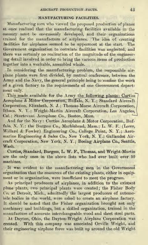
AIRCRAFT PRODUCTION -FACTS. 43
MANUFACTURING FACILITIES.
Manufacturing men who viewed the proposed production of planesat once realized that the manufacturing facilities available in the
country must be enormously developed, and their organizationstrained for the manufacture of airplanes. The idea of creatingfacilities for airplanes seemed to be uppermost at the start. TheGovernment organization to correlate facilities was neglected, andthere was certainly no realization of the magnitude of the engineer-
ing detail involved in order to bring the various items of production
together into a workable, assembled whoje.
In considering the manufacturing problem, the responsible air-
plane plants were first divided, by mutual conference, between the
Army and the Navy, the general principle being to confine the workof a given factory to the requirements of one Government depart-ment only.
This made available for the Army the following plants: Curtiss
Aeroplane & Motor Corporation, Buffalo, N. Y.; Standard Aircraft
Corporation, Elizabeth, N. J. ; Thomas-Morse Aircraft Corporation,Ithaca, N. Y. : Wright-Martin Aircraft Corporation, Los Angeles,
Cal.; Sturtevant Aeroplane Co., Boston, Mass.
And for the Navy : Curtiss Aeroplane & Motor Corporation, Buf-
falo. X. Y. : the Burgess Co., Marblehead, Mass.; L. W. F. (Lowe,Willard & Fowler) Engineering Co., College Point, N. Y.
;Aero-
marine Engineering & Sales Co., New York, N. Y.; Gallaudet Air-
craft Corporation, New York, N. Y.; Boeing Airplane Co., Seattle,
Wash.
Curtiss, Standard, Burgess, L. W. F., Thomas, and Wright-Martinare the only ones in the above lists who had ever built over 10
machines.
It was evident to the manufacturing men in the Government
organization that the resources of the existing plants, either in equip-ment or in organization, were insufficient to meet the program.As principal producers of airplanes, in addition to the existant
plane plants, two principal plants were created; the Fisher BodyCo. at Detroit, Mich., admittedly the largest producers of automo-
bile bodies in the world, were asked to create an airplane factory.
It should be noted that the Fisher organization brought not only
machinery and buildings, but a skilled organization, trained in the
manufacture of accurate interchangeable wood and sheet steel parts.
At Dayton, Ohio, the Dayton-Wright Airplane Corporation was
created. With this company was associated Orville Wright, and
their engineering airplane force was built up around the old Wright

44 AIRCRAFT PRODUCTION PACTS.
group. Great buildings recently finished for other purposes were
at once utilized.
In addition to these two large sources of supply the SpringfieldAircraft Corporation at Springfield, Mass., was put together byMessrs. J. G. White & Co. and J. G. Brill & Co.
Certain interests on the Pacific coast also created several plants in
California, some of which ultimately became satisfactory producersof training planes.
In addition to the principal plants for the manufacture of air-
planes, it was thought necessary to initiate the production of spare
parts in many relatively minor plants. This was done for two rea-
sons; first, to increase the capacity of the regular airplane plants,
relieving them of the burden of making spares, and, second, to start
to educate the other manufacturers up to the point where they might
wisely undertake the manufacture of complete airplanes.
The manufacturers called upon to undertake the production of
spares were largely makers of automobile bodies. To a lesser extent
orders for spare parts were placed with the smaller airplane com-
panies. Among the principal producers of spares were :
The Metz Co., Waltham, Mass.; Sturtevant Aeroplane Co., Ja-
maica Plains, Mass.;Wilson Body Co., Bay City, Mich.
;West Vir-
ginia Aircraft Corporation, Wheeling, W. Va.;The Rubay Co.,
Cleveland, Ohio; Engel Aircraft Co., Niles, Ohio, and Hayes-Ionia
Co., Grand Rapids, Mich.
The record of adaptability, energy, and drive with which the
manufacturers attacked the plane program is worthy of the best
production traditions of this country. The ultimate results attained
both in quality of workmanship and speed of production exceed the
world's best records. Delays in reaching quantity production were
clue to the lack of drawings, specifications, and accessories resulting
from the previous inexperience of the United States in aeronautics.
TRAINING PLANES.
TYPES.
A primary training plane carries the student and the instructor,
generally placed one behind the other. Each has a full set of con-
trols and these are interconnected, enabling the instructor either to
do the flying, or correct the student's false moves, or let the student
do all the flying. Primary training planes are relatively slow (75
miles per hour) and especially require an engine so reliable that
little skill or attention is required.

AIRCRAFT PRODUCTION FACTS. 45
Evidently the first requirement of the Air Service was training
planes, and the decision to use the Curtiss JN-4, with the OX-5
motor as the standard, primary training plane, has been proved wise,
especially as the delay in securing rotary engines would have pre-
vented prompt deliveries of planes using that type of engine.
A few Penguins, a kind of half airplane that never really leaves
the ground, were built, but this (French) method- of training was
never adopted.The Standard J-l plane, with the Hall-Scott A-7-A engine as a
secondary source of primary training plane, has been criticized, but
it is fair to state that the difficulties encountered were not with the
planes themselves, and not with the original engine, but rather due
to the modification of the intake of the engine, which made the
machine uncertain under cold weather conditions.
Advanced training machines are faster (about 105 miles per hour)and carry various equipment to train observers, gunners, photogra-
phers, radio men, etc. The plane chiefly used in this country for
this work was the Curtiss JN4-H and JN6-H, substantially the same
as the slower Curtiss training plane, but with a 150-horsepower
Hispano-Suiza engine.
The final training in France was in French-built Nieuports and
regular fighting machines.
PRODUCTION OF TRAINING PLANES.
The airplane plants were, without exception, all started on train-
ing machines. The reason for this was twofold : Training machines
were wanted first, and in addition to this fact, neither engines nor
approved designs were available for fighting machines. In general
the production of the training machines kept up with the engine
production, and particularly the Curtiss plant produced JN4 ma-
chines at a pace far beyond anything previously obtained.
The supply of spare parts was for a long time insufficient for the
needs of the training fields. The importance of spare parts had
not been realized, and when proper quantities were ordered manymanufacturing difficulties were encountered. The lack of a proper
supply of spare parts may be charged to :
The lack of a proper realization of the quantity required at the
time of requirement; placing orders with new companies; the lack
of proper drawings.As the supply of training planes met the demands of the fields,
the production was reduced. The maximum production of JN4^Dand SJ-1 (primary training) was 756 in March, 1918. The maxi-
mum for advanced training machines JN4-H, JN6-H, S4-C was

46 AIRCRAFT PRODUCTION FACTS.
427 in July, 1918. The actual production of training planes may be
Bummarized as follows :
Month.

AIRCRAFT PRODUCTION FACTS. 47
nance and lacking many other accessories which were later recom-
mended as essential to a fighting machine. The plane had to be re-
designed and altered to take our machine guns, our instruments, and
our accessories, and fitted to receive the Liberty engine, as well as
much additional equipment above that with which the sample was
furnished or designed.The first DeHaviland plane was flown at Dayton, October 29,
1917, and this identical plane was flown by Mr. Rinehart, of the
Dayton-Wright flying force until March, 1919, and known all over
the country as the Canary Bird. It is now a part of a permanentexhibit in the Smithsonian Institute.
Howard M. Rinehart's part in developing the American air pro-
gram is known to the few. Trained by Orville Wright himself in
1912, and after an extensive experience in radio work, he became a
military flier for Gen. Villa in 1915, -flying the Wright Model H-Smachine.
Later in the Wright Flying School he trained over 200 fliers.
After connecting himself with the Dayton-Wright Airplane Co. he
did the major portion of the development flying with the DeHavi-land-4 machine. Only those who went througk the DeHaviland
problems of the winter of 1917-18 realize the degree of HowardRinehart's devotion to the work.
During the months of December, January, and February the in-
finite problems surrounding the installation of the equipment de-
manded on the DeHaviland-4 were struggled with, and on the 8th
day of April the machine known as No. 31 was completely finished,
and established as the model for the future DeHaviland-4.
The characteristics of the DeHaviland are as follows:
Endurance at 6,500 feet, full throttle 2 hours 13 minutes.
Endurance at 6500 feet, half throttle 3 hours 3 minutes.
Ceiling 19,500 feet.
Climb to 10,000 feet (loaded) 14 minutes.
Speed at ground level 124.7 miles per hour.
Speed at 6,500 feet 120 miles per hour.
Speed at 10,000 feet 117 miles per hour.
Speed at 15,000 feet 113 miles per hour.
Weight, bare plane 2,391 pounds.
Weight loaded 3,582 pounds.
The actual production of service planes, airplanes built in this
country and fully equipped to fight in France, was confined to
DeHaviland^i machines, which is an observation two-place biplanewith Liberty motor.
The following table of production of DeHaviland-4 machines from
all sources is of interest :

48 AIRCRAFT PRODUCTION FACTS.
Production of De Haviland-4 Machines.
November, 1917.
December
January, 1918
FebruaryMarch
April
MayJune __

AIRCRAFT PRODUCTION FACTS. 49
has been under way since December, 1917. There has been muchcriticism of the cancellation of the Spad order.
The Spad sample arrived in New York, September 12, 1917 and
was received at Buffalo, September 25. Work on this plane, however,was finally stopped some tune in December, based on recommenda-
tions from Gen. Pershing that the United States should leave produc-tion of single-place fighters to Europe. Cable No. 375, paragraph 2,
dated December 14, 1917, indicates clearly the instructions of the
American Expeditionary Forces, with respect to the single-place
fighter of which type the Spad was a leading example." United
States should leave production single-place fighter to Europe"
(quo-tation from Cable P-375, pr. 2).
This opinion was later changed partly because of a growing con-
fidence in American airplane manufacturers and partly because of
inability to obtain prompt and adequate deliveries of chasse planesfrom European manufacturers. At the time of signing the armistice,
several single-place fighters were being developed in the United
States by both American and foreign engineers. It was planned to
choose the best two of the planes for production in this country ;this
production could not have started until late in 1919 or early in 1920.
THE BRISTOL.
The necessity of a two-place fighter was understood from the
start. The Bristol fighter sample arrived in New York on August25, 1917, and in Washington on September 5, 1917. Government
engineers at once began redesigning the machine to take the Lib-
erty-12 engine and ordnance and other accessories of American manu-facture. There has been much criticism of redesigning the Bristol
fighter to take the Liberty-12. In other words, to equip it with a
400-horsepower engine rather than a 275-horsepower engine. Later
development of two-seater fighters around the Liberty-12 indicates
the fallacy of criticizing the Bristol program from this point of view.
It is true that there were repeated changes in the engineering man-
agement of the Bristol job, beginning with purely Government engi-
neers, then Government engineers combined with the drafting force
of an airplane factory, then placing the entire responsibility on the
factory without, however, offering the manufacturer an opportunityto correct the basic principles involved, then completing the machine
under the direction of Government engineers. Result in brief wasthat in June, 1918, the Bristol fighter with Liberty-12 engine was
definitely abandoned.
THE LEPERE WITH LIBERTY-12 ENGINE.
At the same time, other brilliantly successful efforts were under
way to design the two-place fighter around the Liberty-12. OnJanuary 4, 1918, Capt. Lepere, a French aeronautical engineer, for-

50 AIRCRAFT PRODUCTION FACTS.
merly with the French Government at St. Cyr, started designing such
a machine. On May 18, 1918, a contract was made with the Packard
Motor Car Co. to provide shop facilities for the production of 25
experimental planes, under the direction of Capt. Lepere.The result of Lepere's efforts from the very start met with the ap-
proval of manufacturing men because of the clean-cut perfection of
the design. The plane was really being created around the Lib-
erty-12 engine rather than an attempt to fit the engine to some exist-
ing plane.
The actual results in the air are only partially shown by the fol-
lowing figures:
Altitude.
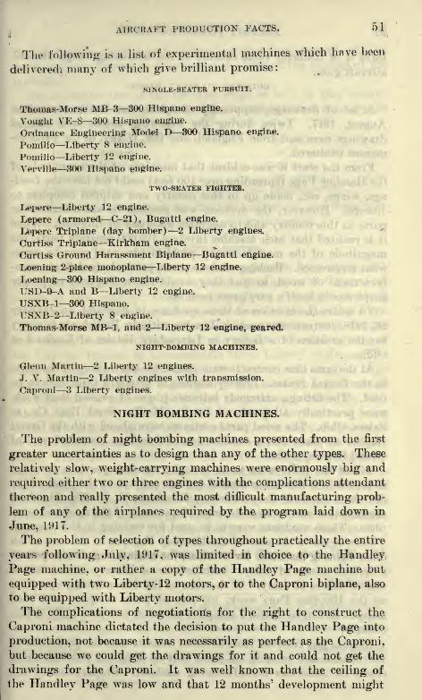
AIRCRAFT PRODUCTION FACTS. 51
The following is a list of experimental machines which have boon
delivered* many of which give brilliant promise:
SINGLE-SEATER PURSUIT.
Thomas-Morse MB-3 300 Hispano engine.
Vought VE-8 300 Hispano engine.
Ordnance Engineering Mortal Tf 300 Hispano engine.
Pomilio Liberty 8 engine.
Pomilio Liberty 12 engine.
Yerville 300 Hispano engine.
TWO-SEATER FIGHTER.
Lepere Liberty 12 engine.
Lepere (armored C-21), Bugatti engine.
Lepere Triplane (day bomber) 2 Liberty engines.
Curtiss Triplane Kirkham engine,
Ourtiss Ground Harassment Biplane Bugatti engine.
Loening 2-place monoplane Liberty 12 engine.
Loening 300 Hispano engine.
USD-9-A and B Liberty 12 engine.
USXB-1 300 Hispano.USXB-2 Liberty 8 engine.
Thomas-Morse MB-1. and 2 Liberty 12 engine, geared.
NIGHT-BOMBING MACHINES.
Glenn Martin 2 Liberty 12 engines.
J. V. Martin 2 Liberty engines with transmission.
Caproni 3 Liberty engines.
NIGHT BOMBING MACHINES.
The problem of night bombing machines presented from the first
greater uncertainties as to design than any of the other types. These
relatively slow, weight-carrying machines were enormously big and
required either two or three engines with the complications attendant
thereon and really presented the most difficult manufacturing prob-lem of any of the airplanes required by the program laid down in
June, 1917.
The problem of selection of types throughout practically the entire
years following July, 1917, was limited in choice to the Handley.
Page machine, or rather a copy of the Handley Page machine but
equipped with two Liberty-12 motors, or to the Caproni biplane, also
to be equipped with Liberty motors.
The complications of negotiation's for the right to construct the
Caproni machine dictated the decision to put the Handley Page into
production, not because it was necessarily as perfect as the Caproni,but because we could get the drawings for it and could not get the
drawings for the Caproni. It was well known that the ceiling of
the Handley Page was low and that 12 months' development might

j)2 AIRCRAFT PRODUCTION FACTS.
leave it of doubtful value because of the increasing range of anti-
aircraft guns.BUILDING HANDLEY PAGES.
A set of drawings, supposedly complete, was finally secured in
August, 1917. Twice during the following winter new sets of
drawings were sent from England, and few, if any, of the parts re-
mained unaltered.
From the start it was evident that machines of the magnitude of
the Handley Page (spreading over 100 feet) could not have the fusel-
age, wings, etc., made up in this country and shipped complete to
Europe. However, the decision was reached to manufacture the
parts in this country and to assemble machines in England. Whenit is realized that each machine involves 100,000 separate parts, the
magnitude of the manufacturing problem presented may be some-
what understood. Packing of these parts, particularly delicate mem-bers made of wood, so that they would reach England in proper
shape was in itself a very great problem.To secure the erection of these machines in England, on January
26, 1918, contract was made in London with the British air ministryfor the creation of a factory in Lancashire district of England at
Oldham.At the same time contracts were placed for the making of the parts
in the United States. Liberty engines of standard type were to be
used. The fittings, extremely intricate pieces of pressed steel work,were practically all produced by the Mullins Steel Boat Co. at
Salem, Ohio. The wood parts contracts were placed with the Grand
Rapids Airplane Co., a combination of furniture manufacturers of
Grand Eapids, Mich.
All of the parts were to be brought together previous to ocean
shipment in a warehouse created for this purpose at the plant of the
Standard Aircraft Corporation at Elizabeth, N. J. The Standard
organization was retained to erect 10 per cent of the machines com-
plete. These machines were to be used for training in this country.
Here again in the case of the Handley Page, as in the case of all
other fighting machines for overseas, the engineering details proveda serious source of delay. Installations of Liberty motors was a
serious source of delay. At the time of the discontinuing operationon the Handley Page work, 100 sets of parts complete had been
shipped to England, and 7 complete machines had been built in this
country.
Reports just received from overseas indicate that the perfection of
fabrication and packing of parts sent to England reflected greatcredit on American manufacturing methods. Preparation by the

AIRCRAFT PRODUCTION FACTS. 53
British for the erection of machines had been long delayed and the
work had only started in England at the time of the signing of the
armistice.
The characteristics of the Handley Page as built in this countrywith twTo Liberty-12 engines, taken from unofficial trials made by the
manufacturer, are as follows :
Speed at ground level 97 miles per hour.
Climb to 7,000 ft 18 minutes 10 seconds.
Climb to 10,000 ft - 29 minutes.
Ceiling 14,000 ft 60 minutes.
Total weight 11,270. pounds.
On these tests 390 gallons gasoline, 20 gallons oil, and seven menwere carried. No guns, ammunition, or bombs carried.
CAPRONl NIGHT BOMBER.
About January 1, 1918, tentative arrangements were made with
the Caproni interests looking toward the production of Caproni bi-
planes in this country; these machines being for night bombing
work, but having a ceiling and speed in excess of the Handley Page.
Capt. de'Annunzio, with 14 expert Italian workmen, with designs
and samples, came to this country and initiated the redesigning of
the Caproni biplane to accommodate three Liberty engines. The
cause of delay in the production of the Caproni was due to a large
extent, to the changes in Signal Corps organization, together with
the difficulties in securing the desired cooperation between the Ital-
ian mission and all American plants in which the work was beingdone. It was not until the last half of 1918," with Capt. de'Annunzio
at the Fisher plant, that it looked as if real progress were beingmade. These facts, together with the multitude of engineering prob-lems involved, limited the actual production of Caproni planes in
this country to a few samples which were under test at the time of
the signing of the armistice. Many of the tools required for the
production of this machine had been made and had the war gone on?
Caproni biplanes would have been available in liberal quantity.
Preliminary Tests of American-Built Caproni at Mineola, Sept. 21-22, 1918.
Test No. 1. Test No. 2.
Speed at ground level .
Climb to 6,500 feet
Climb to 10,000 feet...
100 miles per hour;
103.2 miles per hour.
16 minutes 18 seconds|14 minutes 12 seconds,
33 minutes 18 seconds 28 minutes 42 seconds.
Climb to 11,200 feet|
49 minutes.
Climb to 13,000 feet
Total weight
46 minutes 30 seconds.
12, 904 pounds I 12, 350 pounds.
("Technical Orders" No. 2, November, 1918.)

54 AIRCRAFT PRODUCTION FACTS.
MARTIN NIGHT BOMBER.
In discussing the night bombing program, attention has been re-
peatedly drawn to the complications of foreign machines. In the
fall of 1918, Glenn L. Martin submitted to the Government for test
a night bomber equipped with two Liberty 12's. The spread of this
machine was 75 feet, which carried a capacity comparable with that
of the Handley-Page. The speed of 118 miles at ground level ex-
ceeded that of the Caproni and Handley-Page, and it was evident
that the ceiling would exceed the Caproni, the Glenn L. Martin prob-
ably exceeding 18,000 feet. The Martin machine never reached a
state of actual quantity production, but several experimental ma-
chines were built and tested. It reflected such clean-cut principlesof design with such remarkable resulting performances that it was
confidently believed it was the basis for the coming type of night
bombing machine.
Preliminary Tests of Martin Bomber.
Test No. 1 held at Wilbur Wright Field, October 10, 1918.
Test No. 2 held at McCook Field with machine equipped with stream line wires.
Speed at ground level.
Climb to 6,500 feet
Climb to 10,000 feet....
Climb to 15,000 feet....
Total weight
Test'No. 1. Test No. 2.
113.3 miles per hour 118.8 miles per hour.
10 minutes 45 seconds ! 7 minutes.
21 minutes 20 seconds ... . ! 14 minutes.
9,663 pounds .
30 minutes 30 seconds.
8,137 pounds.
("Technical Orders" Nos. 2 and 3, November and December, 1918.)
PRODUCTION REVIEW.
RESULTS IN THE UNITED STATES.
The actual production in the United States for the Army for the
year ending July 1, 1918, was 6,391 airplanes. At the time of sign-
ing the ar-mistice the figures showed a total of 11,754 airplanes (ex-
clusive of 15 secured by Engineering Department), together with
a reasonable quantity of spare parts.
BRITISH AND UNITED STATES PRODUCTION COMPARED.
The only figures of allied airplane production available are the
British. In considering this comparison it should be rememberedthat a large proportion of the British production was service planes,and that the major portion of our production was made up of the
simpler training machines. In the following comparison the British
figures from the Lockhart report of November 1, 1918, are of interest :
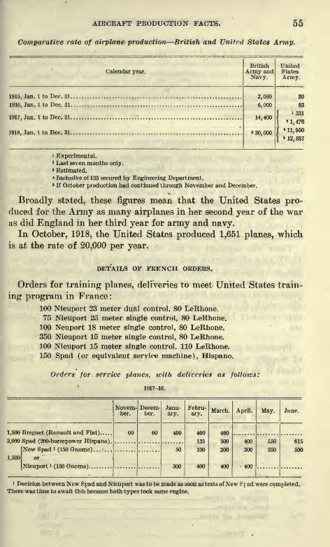
AIRCRAFT PRODUCTION FACTS. 55
Comparative rate of airplane production British and United States Army.
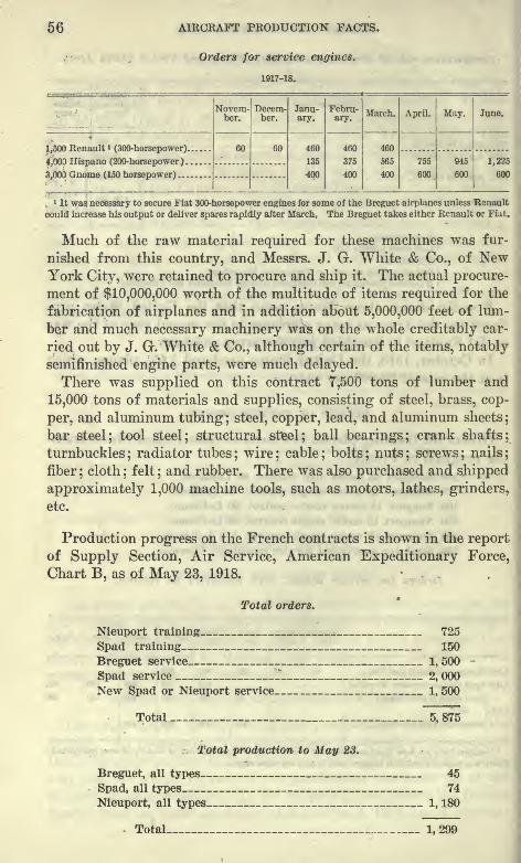
56 AIRCRAFT PRODUCTION FACTS.
Orders for service engines.
1917-18.

AIRCRAFT PRODUCTION TACTS. 57
In addition to the above the French had delivered 532 planes of
various other types during same period, making a total delivered of
1,831 planes as of May 23, 1918. After this date deliveries increased.
This phase of the situation is reflected from another angle by stat-
ing that at the time of the signing of the armistice, the United States
forces in France were using 3,002 foreign-made planes. These in-
clude the above French machines, some from the English, and a few
from the Italians.
CONCLUSION.
At the time of the signing of the armistice there had been de-
livered for use of the Army 16,952 airplanes from the followingsources :
te
United States contractors ; 11,754From England 258
From Italy 59
From France 4, 881
Total 16, 952
Above figures as shown by the Bureau of Aircraft Production and
by American Expeditionary Force Air Service report as of Novem-ber 11, 1918.
. According to report dated July 30, 1918, from Chief of Air Serv-
ice, American Expeditionary Force, the central powers had the fol-
lowing planes on the front July 30, 1918 :
German 2, 592
Austrian 717
Total 3,309
The relative standing of the allies as expressed by planes on the
front is variously estimated, because of the uncertainty of the actual
number of planes in a squadron. Two views are given below, the
smaller figure probably reflects nearer the actual facts :
58 AIRCRAFT PRODUCTION FACTS.
These figures represent fully equipped machines ready for fightingservice and do not include replacement machines at the front or in
depots or training machines in France.
Officers from overseas agree that the above figures are probably
representative. 'They, however, believe that the German service on
spares, simplicity of equipment, and better organization based on
long experience gave the German command much more service per
plane, and essentially overcame the numerical difference.
At the time of signing the armistice the status of American-built
service planes for use in France is reflected by the following figures :
2,091 planes had actually been shipped to France, 1,885 of which
were De Haviland 4 with engines, 204 De Haviland 4 without en-
gines, and 2 were Leperes.
1,040 more planes were at ports of embarkation or were in transit
from American factories to ports.
1,440 planes had actually been received in France.
960 U. S. A. built planes were actually in service in France, 667 at
the front and 293 at A. E. F. training fields.
There had also been delivered to an assembling plant in England100 sets of parts for night bombing planes for assembty in Englandand to be flown to France.
Source of information: Statistics Branch, General Staff, ReportNo. 91.

AIRCRAFT MACHINE GUNS.
NOTE. The production of machine guns is handled by the Bureau of Ord-
nance on requisition of the Air Service.
Fighting in the air is entirely a development of the present war,
and the adaptation of machine guns for all types of aircraft has
practically all taken place since the ^declaration of war in Europe.
During the first year of the -war the application of machine gunswas being developed, but not until the summer of 1915 was it possible
to send out on active service flights airplanes with armament con-
sisting of one or more machine guns.
Records show that a machine gun was successfully fired from an
airplane in this country in 1912; also that the French had a few
heavy airplanes equipped to carry machine guns at the beginningof the war.
Until almost a year after the war began machine guns were not
carried by airplanes on active service, but they were armed with
various weapons, such as service rifles, automatic rifles, automatic
pistols, shotguns shooting large shot held together by wire, and also
equipped with grenades and darts, which were intended to drop on
their adversaries. Needless to say, the damage done by these weaponswas slight, owing to the great difficulty of one moving object hitting
another.
Maj. Eric T. Bradley, United States Army, in August, 1915, was a
flight sublieutenant in the British service. He regularly flew over
the lines in a B. E. plane, armed with a Lee-Enfield rifle or sometimes
with a 12-gauge double-barrel shotgun loaded with buckshot tied to-
gether by wire that swished through the air and occasionally hit
something. Regular service automatic pistols were carried, and there
are many stories of frightening the Hun with Very pistols, which
shot Roman candle balls. Later Lewis ground guns were taken di-
dectly from the trenches and worked from the observer's shoulder.
GUN CONTROL OR SYNCHRONIZING MECHANISM.
The development of methods of so controlling machine guns that
they could be fired through the area traversed by the propeller has59
60 AIRCRAFT PRODUCTION FACTS.
had a vast effect on aircraft armament, and an understanding of this
problem is necessary to a proper understanding of the story of air-
craft armament. What the device under discussion actually does
is, fire the gun only at such times as the bullets will not strike the
propeller blades, that is, the device used must time the gun with the
engine.The various devices utilized for controlling the fire of a machine
gun so as to cause the bullets to miss the blades of the propeller are
commonly known as synchronizing gears or interrupter gears. How-
ever, both these terms are somewhat erroneous, as it is only occasion-
ally that the speed of the propeller is equal to the rate of fire of the
gun, which is the condition of synchronization; also, the gun is not
interrupted, but caused to fire at the proper instant so that the bullet
will not strike the blade of the propeller. The term "gun control "
is a much better name for these devices than either synchronizing or
interrupter gears.
Tractor airplanes which have the engine and propeller in front,
were found early in the war to be better suited for active service
work, owing to their having better maneuvering powers and beingmore easily able to defend themselves. With these planes' were de-
veloped the fixed aircraft machine gun. This gun is fixed rigidly to
the plane, pointing straight forward, parallel to the line of flight.
The first fixed guns were mounted on the top plane so as to shoot
over the arc described by the propeller ;but these were not satis-
factory owing to the difficulty in reloading the gun. To evercome
this difficulty the gun was lowered, which brought its line of fire
inside the circle described by the propeller.
Thus arose the difficulty of shooting into the propeller, and various
attempts were made to solve this problem. The blades of the pro-
peller were armored at the points where the bullets would strike,
with steel of a shape calculated to cause the bullets to glance off,
but this system was never very satisfactory. In other cases linen
fabric was wrapped around the propeller at points where the bullets
would strike to keep it from splintering, as it was found that several
shots could pass through the propeller without causing it to break.
This was the condition on all fronts early in 1915. All ot the
Nieuports had their fixed guns literally shooting through the pro-
peller; that is to say, if the bullet hit the propeller it went throughit if it did not wreck it. As late as February, 1917, Maj. Eric T.
Bradley, United States Army, at that time flight commander in the
British service, flew 40 miles over the Bulgarian lines, fighting with
Lewis guns and no synchronizing device.
Who first invented the device for controlling the fire so as not to
strike the blades of the propeller is uncertain, but it is an admitted
fact that the Germans first extensively used such device on their
AIRCRAFT PRODUCTION FACTS. 61
Fokker monoplanes, which caused so much damage on the western
front in 1915. It was some time after this date that the allies used
similar devices.
The introduction of the so-called synchronized gun was an im-
provement which made aerial combat a large factor of the war. It
seems to be credited to several people. It is difficult to state to whomthe credit of this invention is due. Some give the credit to the
famous Frenchman, Roland Garros.
CONDITIONS IN THE UNITED STATES, APRIL, 1917.
Neither the Ordnance Department nor the Aviation Section of the
Signal Corps had had any experience worthy of the name with air-
craft guns. None of the airplanes used at the time of the mobiliza-
tion on the Mexican border were equipped with machine guns. In
short, the Army was essentially ignorant. The Army was entirely
lacking in experience in these matters.
There had been manufactured by the Savage Arms Co. in this
country Lewis flexible aircraft guns for the British Government.
No aircraft guns of the fixed type had been manufactured in this
country, and nothing was known of the mechanism of gun control,
sometimes called the synchronizer.
None of the gun mounts or other special details connected with
the installation of aircraft armament had ever been produced in this
country.
SPECIAL REQUIREMENTS OF MACHINE GUNS IN THE AIR. .
The operation of the guns must be reliable to a degree. To have a
gun jam may be fatal, and little can be done to overhaul the guns in
the air. If a jam or malfunction occurs at a critical moment, the
gunner is left at the mercy of his adversary. The gun must func-
tion perfectly in any position in which it is liable to be placed bythe maneuvering of the plane. The guns are subject to extreme va-
riations of temperature and must be certain to function in intense
cold, often below zero, as found at high altitudes. The ammunition
must be superperfect to still further avoid the possibility of the
gun jamming.An intensely high rate of fire is essential. On the ground 500 shots
per minute is reckoned as sufficient for the machine gun, but aircraft
guns have now been brought up to 950 to 1,000 shots per minute.
This high rate of fire is important because of the great speed at
which airplanes move. The gunner can only train on his target for
a few seconds at a time, and every possible shot is essential. Whenone considers that if an airplane fires at right angles at a fixed target
with the plane moving at 100 miles per hour and the gun shooting

62 AIRCRAFT PRODUCTION FACTS.
880 bullets per minute the bullets will be spaced 10 feet apart on the
target, the necessity for extreme rapidity of fire is evident.
Aircraft guns are never fired continuously for any length of timer
therefore water cooling is not required. No special cooling devices are
provided for machine guns when especially designed for aircraft use.
TWO DISTINCT TYPES, FIXED AND FLEXIBLE.
Single-seater machines carry only fixed guns, which are attached
with the barrel parallel to the axis of the airplane. These guns are
controlled or synchronized so as to shoot through the circle traversed
by the propeller. They are put in action by a trigger on the joystick of the airplane and are aimed by pointing the entire airplaneat the enemy.
Flexible guns are used with two-place machines and are operated
by the observer or gunner. They are carried on the universal mount,which permits the gun being pointed in any direction.
FLEXIBLE GUNS.
All the flexible aircraft guns used by the allies are based on the
principle of the 'Lewis machine gun, originally invented by Col.
Isaac N. Lewis, United States Army (retired). The Lewis gun as
used by ground troops has been especially modified to make it prac-ticable for aircraft use. Modifications particularly include the elimi-
nation of the cooling radiator and addition of a gas check to reduce
the recoil. The Lewis aircraft gun at the time of the entry of the
United States into the war was being manufactured by the SavageArms Co. for the British Government. It is of particular note that
the Lewis gun principle of a drum magazine is more desirable for the
flexible guns than any type of belt feed, for evident reasons. TheGerman flexible gun, known as the Parabellum, had the belt feed,
with its attendant troubles.
FIXED GUNS.
At the time of the entry of the United States into the war the
Vickers was essentially the only type of fixed gun used on either
English or French planes and was used on all the planes early de-
livered by the French manufacturers for the use of squadrons of the
American Expeditionary Forces.
When the Equipment Division of the Signal Corps faced the ma-
chine gun situation in September, 1917, it was found that the entire
Vickers production in the United States had been previously con-
tracted for and were depended on to supply the early requirements>f the ground troops. As a matter of fact. 4.325 Yickers had been

AIRCRAFT PRODUCTION FACTS. 63
supplied on May 4, 1918 all the types suitable for ground troops and
not suitable for airplanes.
The continued personal efforts of the officers of the EquipmentDivision secured the development of a fixed type of aircraft gun
by the Marlin-Rockwell Corporation of New Haven, Conn. The
original reason for this move was because the Marlin gun was the
only gun available. The wisdom of this move was reflected by the
fact that on June 24, 1918, the Chief of Ordnance presented cable
No. 1168, demanding 7,220 machine guns for 'tank use. Within 24
hours 500 guns were shipped from the Air Service Depot at Fair-
field, by express, to the American Expeditionary Forces. The re-
maining 6,720 guns were forwarded by freight in the next two
weeks from the same source.
The order for Marlin guns was placed in the fall of 1917 in the
face of marked opposition, but resulted in providing sufficient fixed
guns for the American Air Service, and for other purposes as noted
above. At the time of the signing of the armistice no other fixed
aircraft guns were available from production.
PRODUCTION OF LEWIS FLEXIBLE AIRCRAFT GUNS.
The first order for Lewis aircraft guns was placed on December
19, 1917, and up to November 11, 1918, 32,957 of these guns had
been delivered for use by the American Air Service. The deliveries
commenced in February, 1918, with about 1,500 guns per month,
and in the month preceding the signing of the armistice that is to
say, in October, 1918, about 6,000 Lewis aircraft guns were delivered.
A notable accomplishment of American manufacturing was an
increase in the depth of the magazine pan so each magazine held 97
cartridges in place of the previous 47 cartridges.
PRODUCTION OF MARLIN FIXED GUNS.
The Marlin aircraft machine gun, which has been developed and
manufactured by the Marlin-Rockwell Corporation, New Haven,
Conn., has been adapted to all American-built planes which carry
fixed or synchronized guns as part of their armament. The first
order for Marlin aircraft machine guns was placed September 25,
1917, and over 37,500 were produced before December, 1918. Quan-
tity production of 2,000 per month began in January, 1918, and in-
creased rapidly until as many as 7,000 guns were produced in one
month. Our aviators report that this gun compares favorably with
the best machine guns used by our allies, and is entirely satisfac-
tory in every respect. This machine gun shoots .30 caliber ammu-nition at the rate of 600 to 650 shots per minute, and is fed from
a belt which is of the disintegrating metal link type.

64 AIRCRAFT PRODUCTION FACTS.
There are two distinct types of gun control, both in use at the time
of the signing of the armistice. These are the hydraulic and the
mechanical.
The operation of both these types is somewhat similar. In each
case a cam mounted on the engine shaft actuates a plunger when the
device is in operation, which in turn operates the rest of the mech-
anism. In the mechanical gun control the impulse of the cam is
transmitted through a series of rods to the gun, causing the gun to
fire at the proper moment. In the hydraulic gear the impulse of
the cam is transmitted to the gun through a system of copper tubes
containing oil under high pressure.The hydraulic type of gun control, known as Constantinesco control
(CC), was copied for American planes, particularly the DeHaviland
4, which carries two fixed air-craft machine guns (Marlin, each firing
at the rate of 650 shots per minute. At maximum fire, 1,300 shots
per minute could be fired between the blades of the propeller re-
volving at a rate of as high as 1,600 revolutions per minute without
any of the bullets striking the blades of the propeller. Four gunshave been successfully fitted to one plane and timed with these de-
vices so that none of the bullets struck the blade of the propeller.
At the time of signing the armistice 6,827" CC "
gears had been
shipped.
AIRCRAFT AMMUNITION.
Generally speaking, all aircraft ammunition used is of regular serv-
ice caliber. All ammunition is especially gauged so as to eliminate,
as far as possible, the chances of the guns jamming. Even the
regular-service ammunition furnished for use of aircraft guns is
special in the sense that it is picked out for accuracy.
The production of ammunition for aircraft guns has increased very
rapidly, not only because of the increase in use of airplanes, but be-
cause many of the observation machines to-day carry four guns and
the consumption of ammunition per plane has radically increased.
The fact that two fixed guns and two flexible guns are often car-
ried still further reflects the necessity of perfect ammunition. The
primary reason for carrying two of each kind of gun is to immedi-
ately have another gun available in case the first gun jams.Efforts to make the bursts of fire from airplane guns of maximum
effectiveness have led to the development of three distinct types of
ammunition. This special ammunition not only requires the extreme
care in gauging that is applied to service ammunition for aircraft
use, but also involves the special types of bullets.

AIRCRAFT PRODUCTION FACTS. 65
Enormous quantities of this special ammunition were being pro-
duced at the time the armistice was signed; the rate of production
exceeding 10,000,000 rounds per month.
The tracer type of ammunition has a projectile containing a smoke-
producing charge which ignites when the cartridge is fired and
leaves a trail of smoke for about 600 yards. This type of ammunition
was developed to assist the gunner in aiming his gun, and is equally
useful at night or day, as the white smoke can be seen in the daytimeand a bright spark at night.
Armor-piercing ammunition has a projectile which consists of a
hard steel core with a soft nickel casing. As the name implies, the
object of this type of ammunition is to pierce any of the metallic
parts of the airplane, particularly the engine or gasoline tanks. The
soft nickel casing acts as a lubricant and prevents the steel core from
glancing off.
Incendiary ammunition has a projeqtile containing a charge of
yellow phosphorus, and when the cartridge is fired the rifling of the
machine-gun barrel causes a small hole in the case of the projectile
to open and allows the phosphorus to come in contact with the air
and it ignites immediately. This will set fire to any inflammable
part of the airplane which it may hit.
It is customary to load the ammunition belts or containers with
these three types of special ammunition in certain sequences. First,
the tracer cartridge, which assists the gunner in correcting his aim;
then two or three armor-piercing cartridges, which possibly will in-
jure the engine or pierce the gasoline tank ;then one or two incendiary
cartridges which, if by chance the gasoline tank has been pierced, will
ignite the leaking gasoline, thereby setting fire to the machine. This
sequence is repeated throughout the belt or ammunition container
as the case may be. Different pilots use different sequences in loading
special ammunition, according to what they consider the most
effective method.
For the fixed guns, the ammunition is carried in belts carrying a
maximum of 500 rounds for each gun. This belt, as furnished to the
American Expeditionary Forces, is made of small metallic links
held together by the cartridges themselves. As the gun fires, the
links fall apart. Chutes are provided so that the links fall clear of
the airplane. This type of belt was developed especially for aircraft
use to eliminate the problem of taking care of the empty belt or
furnishing a container for the empty belt. The links of the disap-
pearing belt must, of course, equal in number the cartridges con-
sumed. The actual production in this country up to the signing of
the armistice consisted of 59,044,755 links. These links appear to be
10654819 5

66 AIBCEAFT PRODUCTION FACTS.
extremely simple, but the extreme accuracy required created a difficult
manufacturing situation necessitating extreme care. The productionand inspection of these links involves over 36 separate operations.
ARMAMENT SUNDRIES.
The details of fitting the guns to the planes and providing for
proper sights and gun control involve many pieces of work, each
minor in themselves, but as a whole presenting a very material
problem.The sights are simple excepting the so-called unit sight, which
was copied exactly from the English design. The primary difficulty
was in securing the necessary optical glass. Unit sights to the num-ber of 12,621 had been produced at the time of the signing of the
armistice, and 1,550 had been sent overseas to equip foreign-built
planes that had been furnished the American Expeditionary Forces.
The extreme altitude and the difficulty of keeping the gun oil from
congealing makes it necessary to keep the guns warm. A small
electric heater is provided for this purpose. These are small resist-
ance grids fastened to some convenient part of the gun.
TYEES.
The Marlin aircraft machine gun, made by the the Marlin-Rock-
well Corporation, and the Lewis aircraft machine gun, made by the
Savage Arms Corporation, are the two American-built machine guns
actually used on American-built planes up to the time the armistice
was signed. In this type of gun a small amount of the explosive
gas is allowed to act on the head of a piston which operates the
action of the gun, being returned to position by a strong return
spring. The operation of both guns was very satisfactory.
The Browning aircraft machine gun was just coming into quan-
tity production. This gun embodies the best principles of everyknown machine gun, and would probably have replaced all fixed
machine guns of other types in use. It had the high rate of fire of
more than 950 shots per minute and was very accessible and extremelyreliable in every respect. This is a belt-fed gun of the recoil type.

AIRPLANE BOMBS.
NOTE. The production of airplane bombs is handled by the Bureau of Ord-
nance on requisition of the Air Service.
One branch of aerial warfare which was steadily increasing in
effectiveness and magnitude was aerial bombing. Bombs of a sort
were dropped from airplanes in Italy's war in Africa, and also byAmerican soldiers of fortune in the Mexican trouble in 1914. The
huge Zeppelins of the enemy were the first aircraft to attempt
systematic bombing, but their early efforts were not accompanied
by much success, owing to the general ignorance of the design of aneffective aerial bomb. The lowering effect on the morale of the
enemy was, up to the last year and a half of the war, probably as
great a result of bombing as the actual damage caused by the explo-sion of the bombs.
No one who has not tried it can realize the extreme difficulties in
dropping a bomb from an airplane so that it will hit a desired tar-
get. Owing to the great speed at which an airplane travels throughthe air, a bomb when released does not drop vertically but falls to
the ground in a curve. For this reason the bomb must be released
some little time before the airplane is directly over the target andthe ability of an aviator to determine this point accurately is only
acquired through experience.The line of flight of a bomb from the point of release is influenced
by the speed of the airplane, the height of the airplane above the
ground, the shape of the bomb itself and cross currents of air actingon the bomb on its way down.
The Bombs themselves are shaped so as to offer the least possibleresistance to the air and have fins on the tail to hold the bomb steadyand keep it from tumbling.
Quick-release Mechanisms are provided on all bombing airplanes^which hold the bombs firmly in a vertical or horizontal position byhooks or bands around the body of the bombs. Release mechanisms
are usually placed underneath the lower wings or fuselage of the
smaller types of bombing planes such as the De Haviland-4. On the
large types, such as the Handley-Page, the bombs are carried inside
67

68 AIRCRAFT PRODUCTION FACTS.
the fuselage. The bombs are usually released by the observer who has
a small lever in a convenient position for that purpose.
Bomb Sights constitute part of the equipment of all bombing planes.
These sights have numerical scales mathematically calculated so that
when adjusted for height, air speed as shown by air speed indicator,
calculated strength of wind with or against the airplane, two sighting
points are moved into such a position that if the bomb is dropped,when the desired target comes in line with them, it will reach its ob-
jective providing the sight has been set correctly.
Practically all bomb sights produced were an exact copy of the
English high altitude Wimperis. On November 11, 8,371 had been
produced.
American Demolition Bombs are made in different weights, 50
pounds, 100 pounds, 250 pounds, 500 pounds, and 1,000 pounds. The
100 and 250 pound sizes are used mostly. These bombs consist of
a light steel casing filled with T. N. T. or other high explosive, and
a detonator held apart from the .explosive charge by a safety pin.
When the bomb is released from the airplane the safety pin is pulled
out, allowing the detonator to slide down into such a position that
the bomb will explode as soon as it strikes the ground. These
demolition bombs are for use against buildings and all sorts of heavystructures where a high explosive charge is desired.
Fragmentation Bombs are smaller, the size most commonly used
weighing 20 pounds. They have a thicker case than the demolition
bombs and are constructed to explode a few inches above the ground.
These bombs are for use against personnel on the ground or in
trenches and depend upon the scattering of the fragments for effect.
Incendiary Bombs weigh about 50 pounds and contain charges of
oil emulsion, thermit, and metallic sodium, which burn with intense
heat for several minutes. The purpose of the metallic sodium is to
discourage the efforts of anyone trying to put out the fire, as it ex-
plodes violently if water is poured on it. Incendiary bombs are
used against ammunition depots and any structure of an inflammable
nature.

AERIAL PYROTECHNICS.
The part played by pyrotechnics in modern aerial warfare is an
important one and one which must not be overlooked in a discussion
of the various and innumerable accessories and equipment applicable
to the up-to-date airplane. It is interesting to consider that almost
identical forms of the fireworks we burn on Fourth of July and sim-
ilar celebrations are utilized for aerial warfare, and form a valuable
and often vital asset for the aviator.
The principal use to which pyrotechnics are put is that of signaling
from the airplane to the ground and vice versa, also from one plane
to others in the air at the same time.
VERY PISTOL.
For signaling every active service airplane is equipped with one
or more signaling pistols, depending on the number of the crew.
These rather formidable appearing weapons are similar to the Very
signaling pistols used in the trenches, and their ammunition consists
of cartridges very similar to a shotgun shell but larger, containing
different colored stars and a sufficient charge of powder to eject the
stars a good distance into the air. Three colors, red, green, and white,
are furnished, and the color of the star is painted on the end of the
cartridge, also the base is serrated differently for each color so that
the aviator can tell the color by the feel, for use at night. By differ-
ent combinations of these three colors a great variety of signals maybe conveyed. The stars are quite visible in the daytime and are used
for many purposes, such as indicating position of enemy troops,
presence of hostile aircraft, requests for assistance from other air-
planes, as a method of transmitting orders from the leader of a
squadron to other machines in formation, etc. At night the signaling
pistol is of exceptional value in enabling the pilot to make a safe
landing. When approaching the home landing ground the pilot fires
a light of a predetermined color and, if answered by a light from
the ground of the proper color, he is assured that the landing field is
clear of obstruction and other machines and safe to land on.

70 AIRCRAFT PRODUCTION FACTS.
It is the duty of every pilot to destroy his machine in case of beingforced to land in enemy territory, and these signaling pistols have
in many cases been used effectively for this purpose by firing into
the body of the machine or any inflammable part and thereby settingfire to it. There are also a few cases on record of the pilot being able
to hold the enemy at bay with the signal pistol long enough to pre-vent them from any chance of extinguishing the fire.
All Very pistols actually furnished for use of the American Ex-
peditionary Forces were purchased abroad.
WING TIP FLARES, OR HOLT FLARES.
Night flying is one of the most hazardous duties of the aviator,the chief danger being in the difficulty of making a safe landing.
Night landing fields as a rule are well illuminated by flood lights,
but near the front this is not always advisable and owing to the
difficulty of judging the distance of the machine above the groundat night, accidents are not uncommon.
This condition of affairs has been greatly improved by the use of
the wing tip flares which is adapted from the Holt landing flare oi
British design. These flares consist of a small cylinder of magnesiummaterial held in a metallic holder, one of which is fitted under each
lower wing of the plane.
The wing tip flares are ignited by an electric current furnished
a battery or by the generator which supplies the lighting and radio
apparatus, and are controlled by push buttons, one for each flare in
the pilot's cockpit. In making a night landing, when the pilo
judges the plane to be but a few feet above the ground, he presses
one of the push buttons. The flare immediately ignites and burns
with a brilliant light of approximately 20,000 candle power for abou
50 seconds. This light is reflected on the ground by the under surface
of the wing and thereby enables the pilot to judge his landing per
fectly.
AIRPLANE FLARE WITH PARACHUTE.
The requirements of aerial warfare have led to the developmenta very interesting form of pyrotechnics known as the airplane flare
This flare weighs 32 pounds and is contained in a cylindrical sheet
iron case 46 inches long and 5 inches in diameter. The flare con
sists of an illuminating charge, capable of giving 32,000 candle
power for approximately 10 minutes, which is attached to a sill
parachute 20 feet in diameter. The flare is attached to the airplane
by a light release mechanism similar to those holding the bombs
When released a pin wheel on the end of the flare case is revolvec
by the rush of air and ignites the illuminating charge, at the same

AIRCRAFT PRODUCTION FACTS. 71
time detonating a black powder charge sufficient to eject the flare
and its tightly rolled parachute from the case. The parachute im-
mediately opens and the burn-flare descends very slowly, brightly
lighting up the territory in a large area under it.
These flares are used particularly for night bombing raids. Theflares are dropped over the objective, thereby illuminating it and
enabling the bomber to more accurately drop his bombs. It has
been found in many cases when violent antiaircraft fire is encountered
at night that one of these flares will so dazzle the eyes of the anti-
aircraft gunners as to make their aim very inaccurate. Recent ex-
periments have proven that with the aid of these flares it is pos-sible to obtain aerial photographs of good detail on the darkest of
nights. Production on these flares was just starting.
PHOTOGRAPHIC EQUIPMENT.
The story of the production of photographic equipment for the
Air Service of the United States is a story primarily of the rapid
copying of models used by the Allies, followed later by unique Ameri-
can developments.It has been truly said that " the airplane is the eye of the army,"
and it is equally true that the camera is the eye of the airplane.
Contrary to general belief outside of military circles, the principalfunction of the airplanes is the securing of information, and the
camera secures and retains this information with fatal accuracy.The importance of the pictures taken from the air, showing the
progress of the battle, is emphasized by the comparatively large num-ber of pictures which were used by the intelligence officers duringcombat. Illustrative of this point, and as an example of the workdone by the American photographic forces, it might here be well
noted that during the drive in the Argonne district, the American
photographic sections made 100,000 pictures of the battle lines in
four days' time.
The equipment required for the photographic work of the Air
Service can be best understood by having in mind a general classifi-
cation of the wrork to be done.
Mapping is the primary and most important work of aerial photog-
raphy. These mapping cameras all provide that when once started, a
new plate or film will be automatically put in place and exposed, and
the speed of this action is so controlled by the observer in relation to
the speed of the airplane over the ground that a series of pictures
making a continuous photograph of a given strip of territory is
obtained.
Hand cameras, differing from ordinary cameras primarily because
they have much greater focal length. These cameras are for single
exposures used to photograph other airplanes, or perspectives of
ships at sea, or scenes on the ground.
Gun cameras, installed in place of machine guns and used for tar-
get practice. These are either"single shot " cameras that indicate
72
AIKCRAFT PRODUCTION FACTS. 73
the spot held on when the gunner pulled the trigger, or are continu-
ous motion-picture cameras that make an exposure corresponding to
each shot of the gun. This again is used for checking the marksman-
ship of the gunner.
Photographic trucks, or traveling dark rooms, and endless supplies
and equipment are required for handling the work after the exposed
plates or films are delivered on the ground.
CONDITION IN EUROPE IN 1914.
As aerial photography was an entirely new military subject at the
outbreak of the war in 1914, there were no precedents to go by, nor
had any special apparatus been designed for this purpose. Conse-
quently the entire subject of aerial military photography was de-
veloped by the allied armies during the period from August, 1914.
till the cessation of hostilities, and as trench warfare made aerial
photography extremely important, the changes and improvements in
apparatus came with incredible rapidity.
At the outset it was possible to fly at low altitudes and secure sat-
isfactory pictures with such cameras, plates, and lenses as were then
available. As antiaircraft guns were developed, the planes were
forced to attain a higher altitude, and photographic observations in
turn -had to be made from increasingly higher altitudes, making nec-
essar}^ the use of longer focus lenses, special plates, and special color
filters to overcome the haze existing between the camera and the
ground.
MAPPING CAMERAS.
Some work had been done in this country by Arthur Brock, jr., of
Philadelphia ;the G. E. M. Engineering Co. of Philadelphia and the
Eastman Kodak Co. of Rochester had given the matter considerable
attention; and the Engineer Corps, together with the Bureau of
Standards, had given some thought to mapping cameras.
All technical information^ concerning these highly technical sub-
jects developed in Europe during the war had been most carefully
guarded, and most meager and conflicting information was all that
was available in April, 1917.
In June, 1917, the photographic division of the Signal Corps was
organized, large purchases were made of cinematograph cameras,
hand cameras, and view cameras, and at once attention was given to
training the organization necessary to handle this equipment.
Aerial photography received little attention until October, 1917.
At that time attention was stimulated by much valuable information
imparted by the Italian and French High Commissions, and particu-
larly by the arrival of Maj. Campbell of the Royal Flying Corps, who

74 AIRCRAFT PRODUCTION FACTS.
brought with him from England a complete equipment of photo-
graphic apparatus as then used on the British front.
Maj. Campbell at once made clear the amazing volume of accurate
information brought in by aerial photographic observers. He stated
that in April, 1917, approximately 280,000 prints had been issued
to the British service. He also made clear that, due to the importanceof the work and the very rapid development, practices employed one
week at the front were obsolete the next.
The fact that neither the British, French, nor Italians were usingfilms for aerial photography, backed by Maj. Campbell's very decided
opinion that films were unsuitable, lead to the decision to discontinue
experimental work then underway with automatic film cameras. In
fact, it was not until August, 1918, that this line of work was resumed.
A survey of the- situation indicated that the British system dif-
fered but slightly from the French. Both used cameras mounted in
the planes in various types of vibration-reducing suspensions.The French cameras made a relatively large negative, on glass
plates, using cameras fitted with 20-inch focus lenses. Contact printswere made direct from these negatives.The British used 4 by 5 inch plates and cameras equipped with
lenses of from 8-inch to 12-inch focus. Instead of making contact
prints from these negatives, enlargements 6J by 8J inches were madeon glossy paper. It was claimed that this process gave greater con-
trol in printing, and it is undeniably true that the lenses for the
smaller cameras were more easily obtained.
The British system was adopted and was followed throughout the
earlier development of production in the United States.
All mapping cameras are attached by spring suspension to the
fuselage. The cameras point straight down toward the earth and
were originally placed on the outside of the airplane, but the moremodern designs are placed inside, and point directly through the
floor of the fuselage. Cameras are always mounted with a rubber
cushion or other device to minimize the bad effect of the vibration of
the plane.
All of the cameras discussed are designed to take a series of pic-
tures that, together, make a continuous photograph of a given strip
of territory. The earlier cameras were hand operated, followed byspring-driven instruments, which later were followed by designsdriven from a small air screw exposed to the passing air. The latest
type of full automatic camera uses an electric motor drive.
The first camera submitted by Maj. Campbell type C carried
eighteen 4 by 5 inch plates, 12-inch focus, and was hand operated.This was rapidly followed by type E, which was of a similar design,
but of metal, and in December, 1917, the type L camera, of which

AIRCRAFT PRODUCTION FACTS. 75
750 were delivered by the Eastman Co., was put in production. This
instrument was superior, not only because of numerous details in
design, but because an air propeller was used to drive the mechanisms
of the camera that is to say, the plates were changed and the shutter
set automatically, leaving the operator nothing to do but press the
release,
18 BY 24 CM. (FRENCH SYSTEM FOR CONTACT PRINTS).
In January, 1918, Mr. G. S. Dey, of the Eastman Kodak Co., re-
turned from overseas and assisted in reviewing the general situation.
It was agreed that the type L camera, previously mentioned, should
be manufactured with all possible speed. At the same time, the
necessity for a camera of longer focal length, carrying a greater
number of plates, and of a size suitable for contact printing, was
presented by Mr. Dey. He had with him a model of the De Earn
camera, a machine of French design. This machine carried 50 plates
18 by 24 centimeters, the lens was of 20-inch focal length, and the
whole outfit weighed about 90 pounds. None of these machines were
actually produced in this country.
About the same time the Folmer & Schwing Division of the East-
man Kodak Co. developed an 18 by 24 centimeter film camera, also
of 20-inch focal length; weighing, however, only 35 pounds, accom-
modating a roll of films on which 100 successive exposures could be
made. The particularly novel feature of this camera was the" vacuum back." This was a perforated sheet which extended across
the top of the chamber and over the face of which the film passed. Aslight air suction through the perforations served to hold the film
sheet absolutely flat. This air suction was produced by a Venturi
tube, placed where it would catch the rush of air past the airplane.
This automatic Folmer film camera was driven by an electric
motor, and all that was required of the observer was to start the
camera and regulate its speed according to the ground speed of the
airplane. Only six of these cameras were delivered at the time of
the signing of the armistice, but apparently they reflected a marked
step in advance.
CAMERA SUSPENSION.
The vibration of the airplane caused by the motor and the rush of
the plane through the air would be fatal to good photographic re-
sults unless the vibration be effectively eliminated in the camera.
This dictates the necessity of a spring or cushion suspension, in itself
a new development in America, but the British practice was largely
followed in the production in this country. This matter is of great
importance when it is realized that pictures taken from an altitude
of over 10,000 feet indicate where one soldier has walked across a
field.

76 AIRCRAFT PRODUCTION FACTS.
PRODUCTION OF AERONAUTICAL CAMERAS.
At the time of the signing of the armistice there had been deliv-
ered 1,164 aeronautical cameras complete with their spring suspen-
sions, motors, and other accessories. ' This was accomplished pri-
marily through the extremely energetic action of the Eastman KodakCo. and also of Arthur Brock, jr., of Philadelphia, and the G. E. MManufacturing Co., of Philadelphia.
GUN CAMERAS.
Camera guns are used to train aerial gunners. Target practicewith a machine gun in an airplane is not only difficult but also 'dan-
gerous, and the towing of a suitable target is impracticable. Thorn-
ton Pickard, of Altringham, England, had devised a camera whichwas being used successfully in training gunners. This instrument
imitated as closely as possible an aircraft model Marlin machine gun,and in order to make a picture it is necessary to go through the samemovements as in firing a Marlin gun. The picture is made througha circular graticule synchronized with the sight on the fixed machine
gun and, if the film shows that the gunner scored a hit with the cam-
era, he wrould have been equally successful with an actual gun.This "
single-shot"gun camera, known as the Mark III, used a
typical Brownie film, which took one picture each time the triggerwas pulled. This could be used to replace either the fixed gun usu-
ally operated by the pilot of the airplane, or in place of the flexible
gun operated by Ihe observers, but only one picture was taken at
a time.
It is interesting to note that in August, 1917, a sample of the
single-shot camera (Mark III) was obtained from Canada, and a
copy thereof made in one week by the Eastman Kodak Co.
At the time of the signing of the armistice 150 Mark III gun cam-eras had been delivered.
In September, 1917, the Eastman Kodak Co. started work on an
experimental model camera gun Mark I, which would give a " burst "
of exposure with a rapidity approximating that of the machine gunfiring a burst of shots; this was a great improvement over the MarkIII, which made but a single exposure with each pressure of the
trigger. A model was submitted and shortly after the Navy ordered
a number, and Gunnery Training Branch, Signal Corps, placer!
orders for these instruments, which orders were increased from time
to time until in November, 1918, 1,057 Mark I camera guns had been
delivered. *
The Mark I camera was, in common language, a moving-picture
camera, and exactly replaced the magazine on a Lewis gun; that is

AIRCRAFT PRODUCTION FACTS. 77
to say, it was used for training gunners in the handling of their
flexibly mounted Lewis guns. The resulting film, or bromide print,
was a string of silhouettes of the supposed enemy plane, each with
an image of the gun sights superimposed to show where the gun was
held, with reference to the target, at the instant the picture was taken.
LENSES AND RAY FILTERS.
It must be remembered that the camera is only a mechanism to
hold the optical devices. The development and procurement of
lenses was a matter of importance, and as the altitude at which pho-
tographs must be taken increased, the development of ray filters to
overcome the haze effect produced by the moisture in the intervening
atmosphere became essential. The solution of these optical problems
was in itself a matter of vital importance in which America played
no mean part. The success of this work and the importance of ray
filters is shown by two photographs of the same subject, one taken
\vithout a filter and the other taken with a ray filter.
GENERAL EQUIPMENT.
Particular stress is always placed on aerial cameras themselves,
but practically they were only the beginning of successful photog-
raphy. Innumerable sundries were required to produce satisfactory
photographs. Lenses, paper, plates, chemicals, tanks, trays, print-
ing machines, stereoscopes, together with the traveling dark rooms
to do the work in, were all required to properly equip the field forces.
Much of the material on the market was unsuitable.
The magnitude of these matters is indicated by the October ship-
ments of some of the principal items of supply.Over a million and a half sheets of photographic paper were
shipped in October.
Over 300,000 dry plates.
Over 20,000 rolls of film, with 20 tons of photographicchemicals.
Traveling dark rooms, trucks, and trailers were specially devel-
oped to provide dark rooms at any and every point. Seventy-five
complete units of these machines were shipped. These are mobile
photo laboratories, having all equipment necessary for the rapid
production of prints in the field. The truck body is equipped with
a Dyneto generating outfit for generating current used in dark-room
lamps, enlargers, etc. An acetylene generator is also provided. This
may be used when the electric unit is for any reason rendered inop-
erative. The trailer body is equipped with sinks, tanks, enlarging
camera, printing box, and other necessary photographic apparatus.
78 AIKCRAFT PRODUCTION FACTS.
ENLARGING LANTERNS.
At the time of the signing of the armistice 460 enlarging lanterns
had been furnished for use in the field in connection with the 4 by 5
inch negatives made by the aerial form of camera.
CONCLUSION.
The fact that should not be overlooked is that provision had to be
made on airplanes shipped to France for the installation of all of
the various types of photographic apparatus. The vast personnel,
possibly somewhat skilled in photography, nevertheless had to be
trained for aerial photography. All of the development work, every
portion of it technical to a degree, had to be done in America practi-
cally during the last 12 months of the war. Such results as have
been obtained are extremely creditable to the American manufac-
turers of photographic equipment.
AVIATORS' CLOTHING.
Aviators are commissioned officers and when not at work wear the
regular uniform which, as in the case of all officers, is furnished bythe officers themselves.
When at work in the air the clothing equipment is highly special
and is loaned by the Government to the fliers.
When the United States entered the war we had no standards to
work from, we knew little of the problems involved and how far
reaching were these problems. Yet the work covered a multitude of
problems reaching from securing 400,000 dog skins in China to deter-
mining conditions 20,000 feet above the western front.
There had been no standard styles established, or rather there wasa chaos of conflicting styles, many of which were good by themselves,
but would not function with other equipment that was necessary.
PURCHASE PROBLEM.
The purchase of aviators' clothing for the Army was at first made
by the committee on supplies of the Council of National Defense, in
charge of Mr. Julius Rosenwald and Mr. E. Tyner. From there it
was taken over and for a short time was done by the Quartermaster
Department, when it was again transferred to the Bureau f Air-
craft Production, and put in charge of Maj. John E. Hays.In purchasing this material there were several points to be con-
sidered. First, that it should be as warm as possible without beingso cumbersome as to interfere with the movements and efficiency of
the aviator, for when a man is up 20,000 feet, flying at a speed of 100
or more miles per hour, in a temperature well below zero, he can
not be clad too warmly; also that it should be of such sturdy con-
struction as to withstand hard usage and all conditions of weather;and finally that each part should function properly with all of the
other parts.
After many tests and much development, the following outfit was
used:
HEADGEAR.
On the head was worn, in moderate weather, first, a woolen hood
or helmet so designed as to fit closely over the entire head and neck,79

80 AIRCRAFT PRODUCTION FACTS.
extending down well over the forehead to the eyes and around the
neck to the shoulders. In extremely cold weather, or for high-flight
work, a silk hood of double thickness and like design was worn,
having between its layers an electrically heated unit connected with
a generator on the engine of the plane by copper wire cables that ex-
tended through the suit proper. Over this was worn a soft leather
helmet, lined with fur, and extending down over the back of the
head and covering the ears and sides of the face, fastening under
the chin. The face was entirely covered with a leather face mask,lined with wool, and with an opening for the eyes, over which was
worn a pair of goggles.
At times when communication with either the ground or other air-
planes was essential, the radio helmet replaced the fur-lined helmet.
This was made of leather and somewhat similar in design to the other,
but so fashioned as to contain the receivers of a wireless telephone,
enabling a flier to hear what was spoken to him in an ordinary tone of
voice many miles away.
Oxygen masks were worn for high-flight work in addition to the
above equipment. The oxygen mask was made of rubber, which con-
tained a transmitter allowing him to speak as well as hear by wireless.
This mask was attached by a flexible tube to a tank of oxygen carried
in the plane and so arranged as to feed automatically a different
amount of oxygen as different altitudes were reached.
It was found by a series of tests, made in a room so designed as to
create the exact and various conditions that would exist at any known
height, that a man's faculty to respond at sight, sound, or touch be-
came more dormant as the air became rarefied, and consequently the
man in combat who could remain in a normal condition by the use of
oxygen could begin firing his gun sooner than one not so equipped.
BODY CLOTHING.
Over the body was worn a one-piece flying suit, extending from the
feet to the throat, belted and buttoned tight at the anxles and wrists;
this being made of waterproof outer material so arranged as to leave
no opening or crevice when buttoned and lined throughout with fur.
The question of obtaining fur for these linings was a problem. Vast
quantities of fur were required and had to be of extreme warmth, with
a pelt or skin sufficiently strong to withstand rough usage and still
not be of too great bulk, and at a price not over extravagant. It was
determined that a Chinese Nuchwang dog skin met these requirementsbetter than any other, and they were consequently used. This re-
quired practically all of these skins that could be obtained in both this
country and China, and necessitated the lifting of an embargo to bringthese skins into this country, which, through the cooperation of the
War Trade Board, was accomplished.

AIECBAFT PRODUCTION FACTS. 81
When it is considered that the last purchase before the armistice was
signed was for a quantity of between 450,000 and 500,000 of these dogskins, it may safely be said that, at least, it is not the dogs that are
making the nights hideous in China.
Through these suits, between the fur and outer covering, were
placed wire cables terminating in snap fasteners at the wrists, ankles,and neck, to which could be attached a silk-covered wire leading to
electrical heating units, placed in silk gloves, moccasins, and helmets,all of which were warmed by an electric current drawn from the
generator on the engine.
CLOTHING FOR HANDS AND FEET.
On the hands were worn, besides the electrically heated gloves, a
pair of muskrat fur gauntlets, extending well up the arms and of a
special design which allowed the fingers of the glove to remain in a
fur-lined pocket or be withdrawn from it when necessary without re-
moving the glove.
On the feet were worn, in addition to the electrically-heated moc-
casins, a leather moccasin extending well up the calf of the leg and
lined with heavy sheep wool. These were fastened with straps and
buckles.
MISCELLANEOUS EQUIPMENT.
In addition to the above, there were many other items furnished,such as sweaters, leather coats of various lengths, a fur-lined coat,
two styles of hard helmets, used mostly by students and observers,
and many styles of gpggles.
CONCLUSION.
The air clothing problem involved not only quantities of special
material and workmanship far beyond existing resources, but endless
attention to detail.
Many returning fliers state that it was generally acknowledgedthat our fliers were by far the best and most efficiently equipped of
any nation.
The magnitude of the clothing problem can perhaps be best under-
stood by a few figures. The initial allotment of funds for this
purpose was $2,509,000. This was still further increased from later
appropriations, and on November 11 the work in hand for air cloth-
ing involved over $5,000,000.
Items of over 50,000 fur-lined flying suits ($36.25 each), over
100,000 leather helmets of all kinds (about $4.50 each), over 100,000leather coats (from $10 to $30 each), and over 80,000 goggles ($3.50
each) ,reflect the major items.
10654819 6

OXYGEN FOR THE AVIATOR.
The oxygen apparatus furnished to the American ExpeditionaryForces was developed and produced by the Bureau of Aircraft Pro-
duction under the direction of Brig. Gen. T. C. Lyster of the
Medical Section of the Department of Military Aeronautics. These
notes are formulated from information from Capt. E. A. Hults, whohad charge of the production, and are approved by Brig. Gen. Lyster.
Coincident with development along other lines, the maximumaltitude attained by airplanes has increased enormously during the
war. The record for altitude in 1914 was 26,246 feet, and to-day,
January, 1919, the record is 30,500 feet. (Accuracy questionable.)
In 1915, over the western front pilots worked at 7,000 feet without
fear of attack ,from the ground and few machines would fly above
10,000 feet. The "ceiling" with the early equipment was about
12,000 feet.
In the closing months of the war antiaircraft guns on the groundmade 15,000 feet necessary for safety over the enemy lines and tactics
of the air made that machine safest that could fly highest. Actuallythe working ceiling of 18,000 feet was demanded and obtained from
the latest types of planes.
EFFECT OF HIGH ALTITUDE.
At 19,000 feet the pressure of the atmosphere is one-half the pres-
sure at sea level. That means that a given amount of air in the flyer's
lungs gives only half the oxygen, and this lack of oxygen, not the low
pressure itself, makes men"dopey
" and weak at high altitudes. The
determination of these simple facts is an important result of medical
research work done for the Air Service. While the fact seems clearly
proved that extra oxygen is necessary at high altitudes, it is a curious
phase of the flyer's psychology that most aviators still laugh at the
idea.
As the altitude increases the breathing becomes quicker and deeper;
the heart beats faster and faster. The body tries to obtain the req-
uisite amount of oxygen by increasing the amount of air breathed
in a given time and by exposing a greater amount of blood to the
oxygen in the air cells of the lungs. While breathing rapidly and82

AIRCRAFT PRODUCTION FACTS. 83
really in distress, many pilots do not feel any marked inconvenience.
He may feel perfectly fit and well, but he is not as efficient as whennear the ground. His reaction becomes slower, he is less prompt to
judge distance, to aim his guns, to fire, and maneuver his ship,
although he is not conscious of this impairment. He will feel dizzy
but perfectly happy, though as a matter of fact he has lost his judg-
ment, and if he attempts to stay at these altitudes he will gradually
pass into a condition of semi and sometimes total unconsciousness.
EARLY WORK.
The great necessity of efficiently maintaining fliers was broughtabout through a study of the English air casualties during the first
year of the war. These were about as follows : Two per cent due to
the Hun, 8 per cent due to the plane, and 90 per cent due to the men,which clearly indicated that something was radically wrong with the
personnel, and immediate action was necessary. A thorough studyof this situation disclosed the fact that practically all of the flying
personnel was suffering from what was known as oxygen fatigue or
lack of oxygen, being caused by flying so many hours of the day at
high altitudes and not securing enough oxygen to properly feed
the body.The first apparatus was designed for the British air service by
Lieut. Col. Dreyer of the British R. A. M. C., and was made at the
plant of De Lestang at Paris. The demand for these apparatus wasso great that an automobile was kept waiting at the plant for each
apparatus as it was finished and was especially rushed to the front.
An indication of the importance of oxygen is shown by the record
of the 25th Squadron 9th Wing, R. F. C. This was the first squadronto use oxygen equipment on planes in the British service. They were
using the original Dreyer apparatus and found it efficient, sufficiently
at least for Maj. Birley, who was in charge of the squadron to state
that this squadron, in his opinion, was giving six times the service of
any other British squadron.
DEVELOPMENT OP DESIGN.
To design an oxygen equipment which would be entirely automatic,one that would be reliable and efficient, necessitated the building of a
device which embodied several instruments and one that would over-
come many variable conditions. It was necessary to have a device
that would work under variable tank pressures from 100 to 2,250
pounds per square inch with temperature varying from 80 above to
30 below zero (Fahrenheit). To overcome these variables necessi-
tated a thorough study of temperature and pressure effects uponmetals and much experiment. The apparatus must automaticallydeliver the proper quantity of oxygen to either one or two men at
every altitude from 3,000 to 30,000 feet.

84 AIRCRAFT PRODUCTION FACTS.
An original model of the French-made apparatus was brought to
this country to start quantity production. The French apparatus wasa handmade device, each part being carefully fitted by an individual
workman. Under the direction of Brig. Gen. T. C. Lyster, Medical
Research Board of the Medical Section of the Department of Mili-
tary Aeronautics, and the Bureau of Aircraft Production, the de-
velopment and engineering of an oxygen apparatus to meet Ameri-
can requirements and to be adapted to American methods of manu-facture was undertaken.
The entire apparatus had to be redesigned, first to take care of two
men instead of one; second, to reduee the weight, and third, to meet
American methods of manufacture, and fourth, to make the appa-ratus more efficient and reliable. This work was started about the
1st of January, 1918.
The entire Air Service is under great obligations to A. C. Clark
& Co. of Chicago for their untiring efforts to develop the details of
the apparatus to the necessary degree of reliability and ease of manu-
facture.
The equipment consists of a small tank, or tanks, according to the
amount of oxygen carried, the pressure apparatus, the face mask cov-
ering the mouth and nose, and the tube connected with the reservoir.
The mask has combined with it either the interphone whereby the
pilot and observer can talk to each other with ease while in the air, or
in certain cases, the radio receiver.
A brief description of the Dreyer apparatus for regulating the
flow of oxygen is as follows :
1. A high-pressure gauge calibrated in atmospheres to indicate
to the aviator the supply of oxygen remaining in the high-pres-
sure tank.
2. A reducing valve of a flexible diaphragm type, with her-
metically sealed upper chamber. The sealed upper chamber
acts as a temperature compensator.3. A hand-operated shut-off valve, of a special construction,
which can be set to provide a flow of oxygen to one man, to two
men, or to none at all.
4. A regulating valve, the purpose of which is to automati-
cally adjust the flow to the altitude. This is accomplished
by an adjustment actuated by what is practically an aneroid
barometer.
5. A flow indicator, which is simply a small fan wheel suit-
ably mounted to tell the aviator that the oxygen is actually
flowing.In connection with the above apparatus are used the oxygen tank,
various connecting tubing, and the necessary mask. The mask

AIRCRAFT PRODUCTION FACTS. 85
itself,which necessarily contains telephone or radio receivers, as well
as provisions for getting the gas to the aviator, has been an intricate
problem. The aviator must, while wearing the mask, be able to see
and work in a gale of wind exceeding 100 miles per hour.
PRODUCTION.
On May 3, 1918, six complete equipments, including apparatus,
tanks, masks, etc., were sent overseas by special messenger to be
actually tried out on the front. On May 31 the first production
shipment of 200 apparatus was made. To date over 5,000 apparatushave been manufactured and accepted by the Government, and over
3,786 have been floated overseas, this production ranging from a rate
of about 400 per month in May to 1,000 per month in October.
ACTUAL USE.
All military planes flying over an altitude of 10,000 feet are
equipped for the application of oxygen equipment. The following
type of planes all use oxygen equipment : day bombing, pursuit and
chasse planes and a percentage of both night bombing and army and
corps observation, this percentage depending on the altitude at which
these types of planes will fly.
The importance of oxygen equipment necessitated the establishing
overseas of a special oxygen equipment division to take care of the
application of these equipments on planes.
As previously indicated, the oxygen idea has only been partially
accepted by the fliers. Actual use on the front was just starting at
the signing of the armistice.
AIRPLANE RADIO EQUIPMENT.
NOTE. The production of airplane radio equipment is handled by the Signal
Corps on requisition of the Air Service.
Radio equipment for the Air Service divides itself into two prin-
cipal divisions.
First, radio telegraphy, universally used for artillery fire control
and other observation work.
Second, radio telephony, developed for voice command of squad-
rons, and just being tried by the American Expeditionary Force.
RADIO TELEGRAPHY.
Airplane radio telegraphy had reached a relatively high degreeof development when the United States entered the war. The under-
lying principles were the same as those of any other radio telegraph
equipment. Quenched and rotary spark gaps, crystal and audion de-
tectors were all used successfully. Although the use of transmitting
apparatus on military airplanes in hostile operations had been de-
veloped in Europe, many of the earlier successful experiments in
transmitting from and receiving on the airplane were made in the
United States.
The first successful attempt at radio transmission from airplaneto ground was made August 27, 1910, at the Curtiss Aviation Meet at
Sheepshead Bay, Long Island. No message was sent, but intelligible
letters transmitted by the pilot were received on the ground. Capt.
Harry M. Horton, now of the Air Service, designed the transmitting
set, and Col. C. C. Culver, the receiving set used at the time. Flyingin those days required the pilot's constant attention, the sending keyhad to be mounted on the control wheel, and Mr. McCurdy, the pilot,
had to pay so much attention to flying his machine that he could send
only detached letters of the alphabet. The apparatus was crude, as
is all apparatus used in first experiments. The wires of the machine
were used as the "ground
" and the antenna consisted of some 60 feet
of lamp cord, which was thrown overboard, trailing while in flight.
In September, 1911, at the Aviation Meet, Nassau Boulevard, LongIsland, Col. Milling won a substantial prize offered by Gov. Woodrufffor successfully transmitting a wireless message from airplane to
86

AIRCRAFT PRODUCTION FACTS. 87
ground over a distance of 2 miles. This set was designed by Capt.Horton. In the summer of 1912 a wireless message was transmitted
from an Army airplane over Laurel, Md., to Washington, over a dis-
tance of about 25 miles, and in the fall of the same year, at Fort
Riley, Kans., this distance was increased to 50 miles.
Receiving a message on an airplane was a later development. Six
experimental flights were made in the Philippines in December, 1914,
and messages were received over a distance of approximately 6
miles.
All of these earlier experiments were made on airplanes of the
pusher type having the low powered engine of that period behind
the pilot. The ordinary radio receiver could be heard without special
difficulty. The change to the tractor type of airplanes, with the rela-
tively high powered engine in front of the pilot, subjected him both
to the noise of the motor and the blast of the propeller with its terrific
roar. The designing of a receiver usable under these conditions pre-
sented new difficulties.
Serious study of these problems by the Army was initiated in the
fall of 1915 at San Diego. The problem of receiving in the noise
of the tractor motor was successfully solved and messages exchangedbetween planes in flight. For the long distance experiments, the
"quenched" type of transmitting apparatus was used. Receiving
apparatus employed various types of the " audion " for detection and
amplification, and the operator was provided with suitable head-
gear to exclude the noise.
Equipment for airplane radio work is divided into three principal
groups :
Power equipment, either a storage battery or preferably a gen-erator driven by a constant speed air fan. This part of the equipmentfurnishes the energy.Radio equipment, including variable induction coils, variable con-
densers, transformers, and sending key (flame proof). This ap-
paratus generates radio oscillation, i. e., makes the waves.
Antenna equipment, including reel, fairlead, and wire to radiate
the oscillations or waves.
At the time of our entry into the war the allies, particularlyFrance and Great Britain, had highly satisfactory sets developed and
produced for installation on airplanes. These sets were for the
transmission of telegraph signals, and were one-way sets, sending
messages to the ground, but they provided no means of receiving
signals. The acknowledgment of receipt of signals was shown to
the pilot and observer by means of indicator panels displayed fromthe ground stations. The radio telegraph sets were by far the most
important airplane radio equipment during the war. They were
88 AIRCRAFT PRODUCTION FACTS.
used mostly for fire-control work, the airplane locating targets, re-
porting same to battery, and reporting results of shots.
Power equipment. The generator of an airplane radio set is com-
monly driven by an air fan directly attached to the generator which
is fully exposed to the blast of air. The generator must be limited
to the least weight possible and still supply the necessary power.The size of the generator must be kept within certain limits to
avoid excessive wind resistance. The first point was overcome byefficient design, which helped on the second point. The use of alum-
inum wherever possible, and the design of conical head and stream-
tail solved the second.
The problem of driving the generator at a reasonably constant
speed by an air fan moving through the air with the varying speedof a modern airplane involved difficulties both of design and produc-tion. The constant-speed air fans vary less than 2 per cent in speed,
driving the generator at 4,500 revolutions per minute on planes trav-
eling from 40 to 200 miles per hour. The constant speed of the
fan accomplishes two vital results. The tone of spark is kept at a
reasonably constant pitch, and the generator is saved from destruc-
tion by flying to pieces in excessive speed encountered in a nose dive
or on a very fast plane.
Radio Equipment is mounted in sets in instrument cases that are
installed as a unit on the airplanes. Weight and space must be
conserved as far as efficiency and necessary range will permit. Tomeet these conditions no detail of design can be slighted. Special
rice paper is used in condensers to get a suitable capacity in a lim-
ited space. Flame proof transmitting keys are designed, with con-
tacts entirely inclosed, removing the danger of fire from spark.
These keys are made rugged for operation by a man with heavy
gloves or mittens and are provided with a small electric bulb which
glows when key is closed, showing operator set is operating prop-
erly.
The instruments work between the "ground
" and the antenna.
The "ground" on a plane consists of a connection to the engineand framework which are all electrically bonded together. Fine
wires are also woven among the struts of the wings, these also beingconnected to the engine. A plane thus "bonded" is said to be
"metallized."
The Antenna of an airplane is entirely insulated from the plane.
Airplane radio antenna for telegraph work consists of about 300
feet of fine braided copper wire trailing below and behind the planefrom a suitable reel and held in place by a lead weight of approxi-
mately 1J pounds attached to its end. Considerable experimenta-

AIRCRAFT PRODUCTION FACTS. 89
tion took place before suitable wire was decided upon. It must
have the necessary radio characteristics, be strong enough to give
service under adverse conditions, and yet not be so strong as to en-
danger the plane or the life of its occupants in case of the antenna
fouling on other aircraft or upon trees, building, etc., in case of the
plane coming close to earth before the wire could be reeled in.
Difficulty was experienced in the development of a suitable reel
for handling this wire used for the antenna. A reel was finally
adopted which, when released, automatically allowed the wire to
unwind with a centrifugal braking device which prevented exces-
sive speed of unwinding and which admitted of rewinding readilyand of using any desirable length of antenna wire. It was found
that with the lead weight on the end of the wire if a plain reel were
used and allowed to unwind without a governing or braking device
that the force of the weight was sufficient to break the wire when it
was completely unwound.The "
fairlead " for conducting the antenna through the floor of
the fuselage of the plane presented another problem. The function
of a fairlead is to permit the antenna wire to pass through freely,
to be wound and unwound without excessive wear on the antenna
wire and at the same time to insulate the antenna wire from the
plane, and provide a means of suitable connection between the
antenna wire and the electric circuit of the radio equipment.A later development of the antenna consists primarily of two
trailing wires of soft copper without any weights attached. This
design resulted from the necessity of a trailing antenna which wouldnot endanger the machines and their occupants during the maneuver-
ing of close-order flying. This equipment is apparently satisfactoryand has evident advantages of simplicity and economy. In fact
much of the radio telephony is accomplished with antenna consist-
ing of relatively short soft copper wires trailing from the tips of
the wings.
RADIO TELEPHONY.
Eadio telephony was developed in 1910 from the original concep-tion of the value of a system of intercommunication whereby a
squadron commander on the ground or flying in a machine of his
squadron could direct the flight of a squadron by voice command in
the same way and with nearly the same flexibility as an officer directs
the movement of the infantry.The art of radio telephony, as applied to airplanes, was developed
in the United States almost entirely between April, 1917, and Novem-
ber, 1918. Prior to April, 1917, .a few experiments had been con-
ducted showing the possibility of this means of communication. The

90 AIRCRAFT PRODUCTION FACTS.
voice was first transmitted from airplane to ground by radio tele-
phone in this country in February, 1917, at the San Diego school.
Several successful tests of airplane radio telephone equipment oc-
curred during the summer of 1917 and on October 16, 1917, the appa-ratus had been developed to a stage which, on official test, permitted
radio-telephonic conversation between airplanes in flight at a maxi-
mum range of 25 miles and from airplane to ground over a maximum
range of 45 miles. This test was held at Langley Field, Hampton,Va. Samples of the above set were immediately sent to France for
field test, and the first order for production of airplane radio-tele-
phone sets was placed with the Western Electric Co. December 1,
1917.
Vacuum tubes. The history of development and production of air-
plane sets for communication by radio telephone is the history of the
development of the vacuum tubes which, in both theory of operationand difficulty of manufacture, are highly technical. The vacuumtube is the basis for all radio-telephone communication, and in its
present stage of perfection and refinement is directly responsible for
the successful application of radio telephony to the airplane. Thedifficulties of quantity production of vacuum tubes can best be under-
stood by comparing the ordinary electric-light bulb with the vacuumtubes of the radio telephone. The light bulb contains but one electric
circuit with two terminals; the vacuum tubes contain three circuits
with four terminals. The making of the tubes with these circuits in-
volves intricate manufacturing processes, necessitating skilled glass
workers and special materials to secure the essential very highvacuum.
The vacuum tube has many applications. When used for radio
telephony they act as oscillators and as modulators, i. e., by properconnection with the antenna they vary the waves radiated so that
they have the same form as the speech waves of the ordinary tele-
phone transmitter.
The transmitter is another vital accessory of airplane radio tele-
phone sets. Anyone who has heard the roar of an airplane engineat close range, or even a half mile overhead, and then stops to con-
sider how difficult it is to understand a telephone conversation com-
ing from an ordinary telephone in noisy surroundings, will appre-ciate the difficulty of hearing conversation from an ordinary trans-
mitter exposed to the noise of an airplane engine. Two types of
transmitters were designed which practically eliminate engine noise.
One of the features was the cutting away of the inclosing parts of
the ordinary transmitter, thus allowing engine noises to strike both
sides of the vibrating diaphragm equally. Through a special mouth-
piece the voice strikes the transmitter at the proper angle. The
AIKCKAFT PKODUCTION FACTS. 91
transmitter hangs on the chest or on the helmet of the user and is
spoken into, after the manner of operators at ordinary telephoneswitchboards. The receivers were originally sewed in the aviator's
helmet, but owing to the fact that aviators generally have their own
helmet, the latest arrangement is to mount the receivers on a skeleton
headband which is put on before the helmet. The headband andhelmet holds the receivers tightly against the ears and shut out
engine noise, enabling the aviator to hear perfectly.
PRODUCTION.
Previous to our entry into the war airplane radio sets had not been
manufactured in the United States. The telegraph sets followed
French or British principles, but required the development of details
along lines obtainable in this country. The multitude of accessories
involved in complete sets presented"many questions. Storage bat-
teries were a big problem and the final decision of the Air Service
was the use of Edison storage batteries as far as possible. It was
necessary, however, with the SCR-65 set to use the Liberty type of
lead storage batteries.
Dry batteries for telephone work are an important accessory which
presented engineering and production problems. The essential pointto the successful operation of a vacuum tube is a dry battery of ex-
ceedingly small dimensions, containing 15 very small closely packedcells and a voltage of approximately 22 volts and which, due to the
small size of the cells and their close arrangement, deteriorates very
rapidly on the shelf or in use. It was finally necessary, in order to
get a sufficient number of these dry batteries overseas, to make upthe component parts in the factories of this country and ship these
parts overseas, where they were assembled at a special plant estab-
lished for that purpose. This method of supplying dry batteries
had just been established when hostilities were suspended on Novem-ber 11, 1918.
Production of Airplane Radio Sets from April, 1917, to November
11, 1918.
TELEGBAPH SETS.
SCR-65, spark telegraphing transmitting set for transmitting telegraph
messages from airplane to ground. Used for instructions in fire-control
work, and is a copy of the British Sterling Buzzer Fire Control Set.
Total produced to November 11, 1918 1, 819
SCR-73, performs the same function as the SCR-65, but is a much more
efficient, more powerful, and more desirable set than the SCR-65, andresembles the French Type
" Y "set, which was the most desirable set
for fire-control work. It is a Rotary Spark Set.
Total produced to November 11, 1918 1,000

92 AIRCRAFT PRODUCTION FACTS.
SCR-54, for use on the ground and is a receiving set for telegraph
messages only. This set was used almost exclusively as a receiving set
for fire-control messages, as it constituted the receiving station for all
telegraph messages sent from the plane to ground. It is a copy of French
Artillery Type, is a crystal detector, and is the ground receiving set for
both types of transmitting sets.
Total produced to November 11, 1918 7,752
TELEPHONE SETS.
SCR-59, used in airplanes for receiving voice messages only, and has
no transmitting equipment. The purpose for which it was designed
was to enable the pilot to receive voice commands in formation flying
and in flying instruction.
Total produced to November 11, 1918 6, 509
SCR-67, for use on the ground, is a radio telephone set, and capableof transmitting and receiving voice messages. It is somewhat more
powerful than the corresponding set used in the plane.
Total produced to November 11, 1918 527
SCR-68, radio telephone set used on the airplanes for both transmittingand receiving voice message to and from the plane while in flight.
Total produced to November 11, 1918 3. 150
Interphone sets (not radio).
SCR-57, interphone set, which is a refinement of the ordinary telephoneand is used between pilot and observer during flight. This interphone set
is included as a part of all airplane radio telephone sets.
Total produced to Nov. 11, 1918 3, 978
SCR-89 performs the same function as the SCR-57, except that it pro-
vides for five stations of intercommunication and was intended for use on
large bombing planes, etc., carrying two to five passengers.
Total produced to Nov. 11, 1918 485
CONCLUSION.
The highly technical nature of all radio work makes difficult of
understanding the magnitude of the problems met by the radio engi-
neers and manufacturers of this country between April, 1917, and
November, 1918. Much has been accomplished to meet the military
emergency, which hastened new developments and added to the de-
gree of perfection of the art. The radio telephone has risen from
the experimental stage to the commercial stage and is due to take its
place among the useful arts of the world. Its particular applicationto airplanes will prove of greater value in peace than in war, as it
will become a necessary accessory of the commercial airplane.

THE SENTINEL OF THE SKY.
These notes principally by Mr. Everard Thompson and Capt. H. W. Treat.
Development of the Military Observation or Kite Balloon.
Just 136 years before the signing of the recent armistice, Stephen
Montgolfier and his brother Joseph .allowed their attention to be
drawn to the fact that smoke and clouds have a natural tendency to
ascend.
It was in France in November, 1782, that these two brothers madetheir first balloon experiments and succeeded in sufficinetly heatingthe air in a paper bag to cause it to rise without any apparent force
acting. They were so elated over their discovery that they extended
their work and finally in September, 1783, at Versailles, living crea-
tures took the first ascension in an aerostatic machine. The honored
living creatures were not human, but were a sheep, a cock, and a duck.
The first human beings to take such an aerial ride were M. Pilatre de
Rozier and M. Girond de Vilette, who, soon after the above-men-
tioned experiments, made their attempts, rising successfully to a
height of about 300 feet.
Aside from the military value which has developed and has been
steadily emphasized since the American Civil War, the popularity of
the game was increased by leaps and bounds, and during recent yearsballoon flights have been an essential part of the circus and carnival
as well as providing a good sport for a limited number of enthusiasts.
The aeronaut at side shows drew more attention and caused morehearts to temporarily stop beating than did the gayly bedecked clowns
and trapeze performers.The hot-air balloon, however, would descend when the air became
cooled and when free was always subject to the action of the prevailingair currents. To overcome this latter characteristic, it either had to
be held by a cable or propelled by the. yet undeveloped, portable
power plant. For observation, a stationary balloon thousands of feet
in the air would be ideal for many purposes, especially war operations.
Practical trials were made, but the development of the art had per-

94 AIRCRAFT PRODUCTION FACTS.
fected only the spherical balloon and this, hitched to a cable, bobbed
aloft as does a cork on the ocean waves.
The principles of stream-line shape were not early applied to the
captive balloon and although the captive spherical was used in the
siege of Paris in 1870-1, and as previously stated, in the American
Civil War, it was not developed along its present lines until only a
few years prior to the beginning of the present conflict in 1914.
By way of contrast to the captive spherical, one of the most im-
portant and picturesque instruments of warfare developed in the
great struggle of armed forces for world supremecy, recently closed,
was the captive military observation or kite balloon. The term "kite
balloon " describes it in a single phrase. A balloon of this type rides
the air on the end of its cable much the same as the ordinary kite
rides, and gives in its attached basket a fairly stable observation post
thousands of feet above the earth, from which the observers maydirect artillery fire on distant targets.
At the beginning of the war the artillery fire of the allies was di-
rected principally by airplanes. In this work, however, their use
left something to be desired. While the plane observers could locate
targets fairly well, they frequently lost touch with their batteries
through the difficulty of sending and receiving wireless or visual
signals from the swiftly moving craft. Gradually the captive bal-
loon came into use and by the end of the Avar had practically dis-
placed the airplane as a director of gunfire wherever possible. It
came to be the very eye of the artillery, which, through the balloon,
was made infinitely more efficient than ever before in history of war-
fare.
Sitting comfortably aloft, the observer in the kite balloon basket
had the whole panorama of his particular station spread before himand could note accurately, with powerful glasses, everything trans-
piring in a radius of 10 miles or more. He was constantly in touch
with his batteries by telephone and could give, by coordinated maps,not only the exact location of the target and the effect of the bursting
shells, but could, and often did, give most valuable information of
enemy troop movements, airplane attacks, and the like. He was a
veritable sentinel of the sky, with the keen, long-range vision of the
hawk. He played a part less spectacular than the airplane scout or
fighter in the latter's free and dazzling flights, but his duties were
not less important. Nor did he suffer from ennui during his periodaloft. When a kite balloon went up it became the subject of keenest
attention by the enemy because it was up on business and was certain
to be the cause of damage unless it was forced down. Long-range,
high-velocity guns were turned on it, and planes swooped down on
it from great heights seeking to pass through the barrier of shells

AIRCRAFT PRODUCTION FACTS. 95.
from antiaircraft guns and get an "incendiary bullet
"through the
fabric of the gas bag, which meant the ignition of the highly inflam-
mable hydrogen gas, the quick destruction of the balloon and per-
haps the occupants of the basket as well, unless they could get awayin their parachutes.From the time the gas leaped into flame until the explosion and
fall of the balloon was rarely over 15 or 20 seconds, so quick work
was necessary for the men in the basket to jump to safety. The
pilot of the airplane could dodge and slip away from the guns, not
so the pilot of the kite balloon anchored to its windlass from 2 to 5
miles behind his own lines. He had to take what was coming to him
without means of defense. He had to carry on his scientific calculations
unconcernedly, and in his spare moments had the questionable pleasure
of watching the flash of an enemy gun on a distant hill, directed on
him, and then waiting 20 or 30 seconds for the whining messengerto reach him, while he pondered on the accuracy of the enemy gunner.As a matter of fact, few direct shell hits on a balloon were re-
corded in the recent war. Most of the balloons brought down were
brought down by "incendiary bullets" from diving planes. Some
plane pilots made a specialty of hunting"sausages," a nickname given
to kite balloons because of their shape, and became very expert at it.
Between September 26 and November 11, 1918, 21 American balloons
were lost, of which 15 were destroyed by enemy planes and 6 by
enemy shells. The enemy lost 50 balloons during the same period on
the same front. Balloon companies' aircraft guns drove off manyenemy attacks, and one company brought down two enemy planes
with machine-gun fire in two consecutive days. The importance of
the work of the allied kite balloons is strongly emphasized by the
fact that the Germans gave official credit to their aviators of one and
a half planes for every balloon brought down.
The average life of a kite balloon on an active section of tha
western front was estimated to be about 15 days. Sometimes it onlylasted a few minutes. There is a record of an American balloon
passing unscathed through the whole period of American activity
on a busy section of the front. It is generally considered that a
balloon which has seen five or six months of ordinary nonwar service
has done its duty, and is unsafe because of the deterioration of the
fabric, but there are many cases of a longer and safe useful service.
There are also many cases of the balloon fabric becoming unservice-
able in a month or two, and the balloon has had to be discarded
because of high permeability to gas. Such cases are generally due
to rough or careless handling. Inflated balloons at the front were
taken safely over open fields, through country strewn with shell
holes and barbed wire. In several instances they were transported,
without a windlass, a distance of 6J miles at a time. In the Meuso

96 AIRCRAFT PRODUCTION FACTS.
offensive between September 26 and November 11, American balloons
made an aggregate advance of over 264 miles.
When the war broke out in August, 1914, Germany had, perhapsa hundred of the kite or "
sausage"
balloons, France and Englanda very few. The German type was known as the " Drachen " andconsisted of a gas cylinder of rubberized cotton cloth 65 by 27 feet
with hemispherical ends. For stability, a lobe, approximately a
third of the diameter of the cylinder, was attached to the under-
body of the gas bag and curved up around the end. This lobe, madeof lighter rubberized fabric than the gas bag itself, automaticallyfilled with air as the balloon ascended and acted as a rudder to hold
the balloon in line. For further stability, three tail cups, one be-
hind the other and with mouths open to the wind, were attached to
the rear of the balloon. These cups, 10 feet apart, also filled with
air and helped to keep the balloon from swinging in high winds.
France, England, and the United States had a few of the Drachen
balloons and variations of that type, but they had hardly passedover the experimental stage when the Germans swept over Belgium.While the Drachen balloon was a rather clumsy affair and proved
unstable in high winds, its importance as an adjunct to the artillerj^
could not be ignored. The results of its work became daily more
evident. The armies of France, England, Italy, and America all
made experiments tending toward improvement of this type which
should give greater stability in the air and permit higher altitudes
being attained. It remained for Capt. Caquot, of the French Army,to produce a kite balloon with both of these qualities, and his nameis now used as a designation of the type which he invented and
which was in general use by the armies and navies of France, Eng-land, and America during the last year of the war. Italy developeda kite balloon somewhat different from existing types which was
very efficient. A compliment to the efficiency of the Caquot was paid
by Germany when her army adopted this type of kite balloon and
abandoned the Drachen as soon as possible.
The Caquot type" R "
is an elongated gas bag 93 by 28 feet in its
largest diameter, made of rubberized cotton cloth and sharplystream-lined. Its capacity is 37,500 cubic feet. Hydrogen gas is the
ascensive power used and lifts the cable, two men, basket, and all
other equipment to a maximum altitude, in the best weather condi-
tions, of over 5,000 feet. It has a balloonet or air chamber within
the main body of the gas envelope, which, as the balloon ascends,
fills automatically with air through a simple scoop placed under the

AIRCRAFT PRODUCTION FACTS. 97
nose of the balloon. The air and gas chambers are separated by a
diaphragm of double-ply cloth with a film of rubber between the
two plies. This diaphragm is attached to the inner side of the en-
velope, well down below the equator, by sewing, cementing, and
taping, preventing absolutely the entry of air to the gas chamber
above it.
When the balloon is fully inflated the diaphragm rests on the
underbody of the gas envelope and there is no air in the balloonet.
When the balloon rises, the gas, by its natural expansion, would
burst the envelope, but this is prevented by a valve set to relieve the
gas pressure before it reaches the danger point. When the balloon
descends, lacking its several hundred feet of hydrogen which has
escaped into the air, it would lose its shape and grow flabby, a con-
dition of possible danger. Here the balloonet, or air chamber, comesinto play. As the air is driven by the wind through the scoop the
diaphragm rises and takes up the lost bulk in the gas envelope above ;
thus gas losses are taken up by air by what amounts to an elastic
air envelope below the gas envelope and separated from it by the
diaphragm, through which no air can pass.
Three lobes of rubberized cotton fabric, but lighter than the en-
velope fabric, since they have to hold only air, are spaced equi-distant around the circumference of the rear third of the balloon,
and give increased stability. They are filled automatically by the
wind, if it blows, expand to their full extent, and act as rudders to
hold the balloon steady. If there is no wind there is no need of the lobes
or steadying rudders and they then hang loosely, particularly the
two upper ones, like elephant ears. The Caquots are frequentlycalled "
elephants" because of the drooping lobes or " ears " when
not filled with air. The Caquot has no tail cups, rides nearly hori-
zontally, with consequently a small strain on the cable. It has sus-
tained winds as high as TO miles an hour.
TJNITED STATES CONDITIONS, APRIL, 1917.
When the United States entered the war in April, 1917, the Armyand Navy were practically without this type of craft, and the knowl-
edge of its construction was extremely limited. Developments in
Europe had been carefully watched, however, and a few balloons
made by some of the larger rubber companies. During the mobiliza-
tion on the Mexican border, there was but one captive balloon in
service and that one was a gift to a local National Guard organiza-tion by the Goodyear Tire & Rubber Co., of Akron, Ohio. Lackingadequate plans and specifications when the call began to come forthese balloons, progress in production was necessarily slow. Therewas a tendency to develop individual ideas, improvements, and
10654819 7
98 AIRCRAFT PRODUCTION FACTS.
inventions on the balloon, things disastrous to standardization. In
April, 1917, the whole production of military observation balloons
in the United States was two or three per month. The various rubber
manufacturers, especially the Goodyear and Goodrich organizations,
at Akron, Ohio, on request of the Government, went whole-heartedlyinto the work of quantity production, directed by the EquipmentDivision of the Signal Corps, United States Army, which organiza-
tion eventually developed into the present Bureau of Aircraft Pro-
duction. As demands increased the United States Rubber Co., the
Firestone Tire & Rubber Co., the Connecticut Aircraft Co., and the
Knabenshue Manufacturing Co. all went just as whole-heartedly into
the problem.
THE BALLOON CLOTH PROBLEM.
There were great difficulties in the way of quantity production of
kite balloons outside of the lack of accurate knowledge on the subject
of actual balloon making. Principal among these was the one of
cotton cloth of proper strength, texture arid in sufficient quantity.
Balloon cloth was a thing practically unknown in this country in
April, 1917. There had never been a call for it. To make a close,
smooth, strong cloth as a base for the rubberizing process, it was
considered necessary to have a weave of approximately 140 threads
to the inch both ways. Only a few mills had made such a cloth and
only in very small quantities. To have balloons on the schedule
required by the War Department, millions of yards of this high-count cloth were required. Cotton manufacturers, when called uponto produce the cloth, undertook the work at first reluctantly, because
it meant practically the development of a new type of weaver and a
great reduction of the output of their looms, which on this cloth,
38 to 44 inches wide, averaged less than 10 yards a day.At first the wastage of imperfect balloon cloth ran very high fre-
quently 60 per cent but by care and persistent effort this was reduced
by the middle of 1918 to perhaps 10 per cent in total from the loom to
the balloon. The wastage was largely caused by"slubs," knots, and
other imperfections of weaving, which prevented an even surface
for rubberizing and consequently impaired the strength and gas
holding qualities of the balloon. Hundreds of inspectors, both fac-
tory and Government employees, were necessary to get an approxi-
mately perfect cloth, and all had to be developed for this work.
The making of balloon cloth in the United States amounted to the
development of a new art for which thousands of men had to be
specially trained in a few months. This alone was an achievement
of no mean degree.
Such was the cooperation of the cotton manufacturers and the
Government that all obstacles were overcome and the manufacturers

AIRCRAFT PRODUCTION FACTS. 99
had progressed from cloth sufficient for 2 balloons a week in April,
1917, to 10 a day in November, 1918. The production of balloons,
too, went forward from small beginnings, with few mistakes or de-
lays and always up to or a little ahead of the schedule set for over-
seas and domestic use. The development of the balloon from nothingto its maximum is one of the bright chapters in the history of air-
craft production in the United States.
To make 10 balloons a day the point of progress in manufacture
which had been reached when the armistice was signed, it was neces-
sary for the cotton mills to weave about 600,000 yards of the special
balloon cloth a month. This meant the work of many hundreds of
weavers and 3,200 looms were actually in use November 11. The
average yardage of a loom per day was about 10. In April, 1917,
only a few hundred looms were availajble.
It was sometimes a desperate race between the cotton mills and
the balloon cutters, but the former kept far enough ahead to prevent
any serious check to the schedule of balloons called for by the Bureauof Aircraft Production. Had the war continued another year, the cloth
yardage demanded by a proposed output of 15 kite balloons a day, to-
gether with other types of balloons and the Navy dirigibles, wouldhave reached a total of about 20,000,000 yards, or enough in a single
width to have reached across the continent from New York to SanFrancisco five times, or nearly halfway around the earth. In the actual
cutting and making of a balloon a large force of inspectors was used
and had to be trained specially for the work. Every step of manufac-ture was watched by Government inspectors to the end that there
should be no possibility of hidden mistakes to endanger the lives of
the pilots and observers. This was all in addition to the factory in-
spection. When a balloon was accepted by the chief inspector it was
right for the work it had to perform.
RUBBERIZED BALLOON FABRIC.
The rubberizing process by which the cotton cloth is converted into
gas-tight balloon fabric and used in the construction of the balloon
envelopes was, during the war, a subject of extensive experimentationand development. Small amounts of balloon fabric had been madebut quantity production was never before attempted in the United
States.
The standard European construction was not changed, but rub-
ber compounds, cures and other processes had to be developed. It is
interesting to note that balloon envelope fabric is made about like an
ordinary sandwich, there being a thin perfect film of specially com-
pounded rubber between two plies of the cotton cloth which has been
described. The outer ply of this cloth is cut on the bias and when
100 AIRCRAFT PRODUCTION FACTS.
plied up in this way, prevents, to a very large extent, any longstraight tear down the grain of the cloth. The threads of the two pliesact at an angle of 45 to each other and distribute the strain suffi-
ciently to stop a snag practically where it started.
In applying to the cotton cloth the rubber film, which is reallythe gas-resisting envelope, the cloth must at times be put throughthe spreading machines 30 to 35 times. This is necessary to build upthe thin rubber films perfectly and without flaws of any kind.
The outside or bias ply of the fabric is"spread
" with a rubber
compound containing a coloring matter, the object being to water-
proof the outer ply, to provide a camouflage for the balloon when in
the air or camped on the ground, and, thirdly, to absorb the actinic
rays of the sun and thus protect the delicate rubber gas film between
the two plies of cloth. On the gas film depends the ordinary life of
the balloon, and it must be protected in every way possible. In somecases coloring matter is also used in the gas film itself, so that both
the heat and the ultra-violet rays, which are so destructive to rubber,
may be more entirely absorbed without affecting the film or heatingand expanding the gas in the balloon.
The developments in this field have kept pace with the other balloon
developments, and the latest reports from the front stated that the
American fabric was not only proving successful but had as an added
feature a characteristic which was the direct means of saving life.
These reports state that the American fabric burns very much slower
than European fabric, giving the pilot and observer more time to get
away in their parachutes and thus prevent the burning balloon fall-
ing on them.BALLOON WINDLASSES.
Everything about the kite balloon presented more or less of a
problem because it was new, and these problems had to be worked out
quickly by the American manufacturer for quantity production. Themobile windlass, for instance, by which the balloon was let up and
pulled down on its cable, had to be developed from nothing. The
genius of the American manufacturer overcame the difficulty, as it did
every other obstacle in the development of war instruments. Steam
was the motive power first used for windlasses, but before the close
of the war America had developed both gas and electric windlasses
which were thoroughly efficient. The best known type of gasoline
windlass was that having two motors, one to rotate the cable drum
controlling the balloon's ascent and descent, and one for moving the
windlass itself. A record pull-down speed of 1,600 feet a minute, or
more than three times as fast as the fastest passenger elevator, has
been attained by the gasoline windlass. The electric windlass de-
veloped a speed of 1,200 feet per minute, but was smoother in opera-
tion, thus compensating for the slightly slower speed. The mobile

AIRCRAFT PRODUCTION FACTS* ' 101
windlass could move on the road under its* own *
power^2(3 'sillies aii
hour and could tow the balloon in the air at the rate of 5 miles an
hour, or better if necessity demanded.A satisfactory windlass had been developed in France and, to be on
the safe side, it was the duplication of this machine which was first
attempted for the use of the United States Army. To duplicate,with American materials and methods, a purely French machinefor which there were no drawings was a difficult and very slow prop-osition. The James Cunningham, Sons & Co., of Kochester, N. Y.,
however, took this work in hand and obtained a delivery of four com-
plete windlasses per week.
American originality of design was shown in both the windlass
designed at the United States Army Balloon School and manufac-
tured by the McKeen Motor Car Co., of Omaha, Nebr., and the wind-
lass designed and manufactured by the N. C. L. Engineering Co.,
Providence, R. I. Both of these windlasses were put in quantity pro-
duction, thus assuring for the Balloon Service a sufficient number of
the best windlasses ever manufactured.
CABLE.
The cable which holds the balloon captive is approximately a
quarter inch in diameter, weighs 1 pound for each 8 feet of length, has
a breaking strength of 7,200 pounds, and is made of seven twisted
strands of plow-steel wire, containing in all 133 separate wires.
This cable, while it accomplished its original purpose, was early seen
to have wonderful possibilities of development. The observers in
the basket must be kept in constant communication with the ar-
tillery and their own windlass and this communication could best
and most efficiently be obtained by the use of the telephone. Thefirst use of the telephone, therefore, had to be an entirely individual
unit with its own separate cable from the basket to the ground. In
this way communication was established but only at the sacrifice
of other desirable features of captive balloon work, such as a de-
crease in possible altitude, increased cable resistance, and the sup-
ply of an extra windlass for winding and unwinding the telephone
cable-
Previous to the entrance of the United States into the war, pre-
liminary experiments in France were being made with the view of
putting the telephone wires in the center of the main cable, thus
doing away entirely with the second cable and windlass. There had
never been developed a satisfactory cable of this construction and
American genius at the John A. Roeblings Sons Co., and the Ameri-
can Steel & Wire Co., was set to work, with the result that not only
was a satisfactory cable developed, but a steady production was at-

102 ATJKTiAFT PRODUCTION FACTS.
tmined, 50$000 feet .per week being delivered regularly by the John A.
Roeblings Sons Co., alone.
The original use of two baskets suspended from each balloon ne-
cessitated a very delicate construction of three separate and thor-
oughly insulated conductors. Before such a cable was put into pro-
duction, the double basket idea was discarded in favor of the singlebasket and consequently a different cable was necessary. An insu-
lated three-wire single-conductor cable, surrounded by 6 strands of
19 wires each was the final and successful cable which was being
actually produced in quantity.
This development of course meant a further development of the
windlass, but without delay the necessary devices to handle this
type of telephone conductor were attached and the eyes of the ar-
tillery, the captive observation balloon, had made one more advance
toward perfection.
HYDROGEN GAS.
A sufficient supply of hydrogen gas was, at the beginning, an-
other of the balloon problems. Hydrogen, before the war, was a
by-product in the manufacture of commercial oxygen, and only a
small quantity was used in this country. But the demand of mil-
lions of cubic feet of this gas was met promptly through the es-
tablishment of Government plants and the expansion of privately
owned plants. Portable hydrogen generators for field service were
developed, but by far the greater part of the gas used at home and
abroad was made at permanent supply stations, and shipped to
points of demand in steel cylinders, each holding about 200 cubic
feet of gas under a pressure of 2,000 pounds per square inch. OnNovember 11 there had been ordered and put into production 172,800
of these cylinders, 89,225 having actually been delivered and putinto service- From these, kite balloons were filled quickly througha manifold filler, which permitted 12 to 24 cylinders to be dra'wn
from at the same time.
The gas made by the portable hydrogen generators involved indi-
vidual problems, as did practically all phases of the balloon produc-tion. In this particular case the machine itself not only had to be
designed and adapted to military uses but the chemicals necessary to
produce the gas had to be obtained. The electrolytic or iron contact
methods were out of the question for rapid generation of gas, and
the problem resolved itself into the adoption of the ferrosilicon-
caustic soda process, by which it was possible to produce in the field,
10,000 cubic feet of hydrogen per hour. Caustic soda was plentiful,
but high-grade ferrosilicon, a product of large electrolytic furnaces,
was scarce, due to the consumption of the available supply in the steel
industry. There were, however, delivered for this purpose 2,482
AIRCRAFT PRODUCTION FACTS. 103
tons, over 2,360 tons being supplied by the Electric Metallurgical
Sales Corporation alone.
When the portable hydrogen generator was not practical or neces-
sary, the high-pressure cylinders and " nurse balloons" were used for
storing gas shipped from long distances. The nurse balloon was
simply a large 5,000 cubic foot rubberized fabric bag used in the same
way as a common steel gasometer, which is familiar to everybody.It is impossible to state the exact quantity of gas used by the Bal-
loon Service, but as one item alone, there were 17,634,353 cubic feet
produced and delivered by private manufacturers previous to the
signing of the armistice. These manufacturers were finally in posi-
tion to meet practically any demand for hydrogen in quantity. This
is only a small part of the total, as it does not include the gas pro-duced by the permanent Government stations in the United States
and France, or that produced by the silicon process in the field.
HELIUM GAS FOR BALLOONS.
Hydrogen is itself an inflammable gas and when mixed with air or
oxygen is dangerously explosive. It has always been a source of greatconcern to balloonists and their dream has been of a non-inflammable,
non-explosive gas. sufficiently light to function as does hydrogen.It was known that " helium " was such a gas, but it was, up to two
years ago, so scarce and expensive that it was hardly given a serious
thought. Not more than 100 cubic feet of helium had ever been pro-duced and it was valued at about $1,700 per cubic foot. It was dis-
covered that certain natural gases in the United States contained lim-
ited quantities of helium and the problem then resolved itself into oneof extracting the helium from the gases in sufficient quantities to
make its use practical. Funds were provided from the Signal Corps,
Navy, and Bureau of Mines, and under the direct supervision of the
Navy and Bureau of Mines the processes of gas liquefaction as used
by the Linde Air Products Co. and the Air Reduction Co. and also
the Norton process, were put into operation with the following result
as reward :
On the day of the signing of the armistice there were, on the docksand ready for loading on board ships, 147,000 cubic feet of heliumwith a prewar value of about $249,900,000. Plants were under con-
struction for the production of this gas at the rate of 50,000 cubic
feet per day at a cost of approximately 10 cents per cubic foot.
This development can not be overestimated, as it opens a new era
in lighter-than-air ship navigation. Under war conditions it makesnil the effects of the incendiary bullet, which has recently been the
cause of the complete destruction of so many balloons and airships.Under peace conditions it opens up the possibilities of new types of

104 AIRCRAFT PRODUCTION FACTS.
construction of dirigible airships, as the dangers from lightning,static electricity, or sparks of any kind have been eliminated.
ARMY AND NAVY.
While the Army and Navy have separate organizations for the
production of balloons these organizations worked hand in hand.
Specifications for cloth and fabric were practically identical for both
branches of the service and the procurement of this class of material
was consolidated with the Arm}7.
The type" E "
kite balloon for the Army and Navy were practi-
cally identical except the Navy used two automatic gas-bag valves,
one placed on each side of the balloon one-third of the way back
from the nose and just above the equator. The Army retained the
French and English method of a single valve in the nose. The
Navy rigging was also slightly different, as was the fabric, which
had to be slightly heavier to withstand the action of the salt air andthe rough handling necessary in the small space available on board
ship.
In October the Navy adopted the Caquot"M "
type, which rides at
an angle of about 25 to the horizontal and is a trifle smaller in gas
capacity since great altitude is not necessary. Kite balloons in the
Navy are used as submarine and mine spotters and as a high point of
lookout. They are towed on a cable from the deck of a warship and
are connected with the deck by telephone.
PARACHUTES.
One of the important accessories of the kite balloon is the parachute,familiar to anyone who has attended a country fair on balloon day.
When balloons began to be shot down, the need for parachutes devel-
oped. At first the individual or one-man parachute was used suc-
cessfully to permit the men in the basket to get away from a burning
balloon, but maps and records were lost. To save these records entire,
the basket parachute was invented. This was considerably larger in
diameter than the individual parachute and when cut away from a
burning balloon brought the basket with the men themselves and all
else it contained safely and quickly to the earth. Few fatalities
occurred in the hundreds of cases in which the individual and basket
chutes were used in actual war service or in training. One balloon
observer was forced to make four jumps from a parachute on the
same day, and another made three in four hours, two balloons beingburned over his head. Thirty balloon jumps were made during the
Argonne offensive alone.
During the entire time the American forces were on the front only
one death occurred as the direct result of a parachute drop, and in
fchat particular instance the burning balloon fell directly on top of

AIRCRAFT PRODUCTION FACTS. 105
the open parachute, setting it on fire and allowing the observer to
fall unprotected the rest of the distance to earth.
It is interesting to note that the use of parachutes is relatively new
compared even with the art of ballooning. The man who developedthe parachute and first descended safely to earth by its means is still
active and enthusiastic over aerial development, and during this warhe has had direct charge of the inspection of all United States Armyballoons and parachutes. To Maj. Thomas S. Baldwin, chief of
United States Army balloon inspection, may be given much credit for
the material success of these new American products. From a life of
aerial exploits of all kinds, under all conditions, and in all parts of
the world, Maj. Baldwin knows what is and what is not safe, andwhen a balloon or parachute is sent into action there is, with the
pilot, always a feeling of satisfaction vof knowing that the best balloon
talent in the world has O. K.'d its serviceability. As a balloonist or
as a true American, Maj. Baldwin has no peer.
CORDAGE.
Cordage was another difficulty of the balloon production. Atfirst balloons were shipped overseas without rigging, since the supplyof cordage was short in the United States and the French believed
they could furnish all the cordage necessary. But the procession of
unrigged American balloons swamped the French riggers, and it
was necessary to develop cordage in this country of very high qualityand in great quantity. In the rigging of a kite balloon there are
about 2,000 feet of different kinds of rope. Hundreds of miles of
rope were made and delivered to the Government by the manu-facturers without serious delay to balloon production.
CONCLUSION.
The development of Army balloons and balloon equipment has
passed through various stages of development since April, 1917,
when there was practically nothing to use as a nucleus for the organi-zation necessary to meet the new demands.
The stages of experimentation, development of new ideas, and,
finally, standardization, have been met with the final result of suc-
cess. Up to November 11, 1918, there were produced for the UnitedStates Army alone, 1,036 balloons of all types, 642 of these "being the
final type R observation balloon. Propaganda and target bal-
loons were developed and produced, as were new type parachutes,canvas balloon hangars, and 1,221,582 feet of steel cable, a sufficient
length of single-strand specially manufactured wire to more than
reach entirely around the globe. Hundreds of other items of no less
importance were required and produced for the balloon service, but
can not be mentioned at this time.

106 AIRCRAFT PRODUCTION FACTS.
The history of balloon production in the United States during the
vvar is a record of achievement second to none in America's war pro-
gram. Beginning with little or no technical and manufacturing
knowledge available in the country, the manufacturers and officers
charged with the balloon program produced in a few months balloons
vvhich stood the hard test of actual service and compared most favor-
ably in all ways with the balloons of the best factories of Europe,where the art of balloon building has been in existence for manyyears. There was never any shortage of balloons after the wheels of
production really began to turn, and had the war continued for an-
other year this country could have supplied our own Army and Navyand our European allies as well with all the kite balloons and equip-
ment they needed.
ARMY BALLOON PRODUCTION.
April 6, 1917-November 11, 1918.
Balloons :
Type R, observation 642
Type M, observation 22
Type G, observation 7
Type J, observation 1
Experimental observation 4
Supply balloons 129
Spherical balloons 10
Propaganda balloons 215
Target balloons 6
Total balloons 1,036Parachutes 256
Windlasses 50
Cable, feet 1,221,582Gas equipment :
Hydrogen cylinders 89, 225
Hydrogen, cubic feet produced by private manufacturers 17, 634, 353
Helium, cubic feet 147, 000
The above production for the Army provided not only for the
requirements of the A. E. F. and the balloon schools in the United
States, but permitted furnishing a substantial quantity of this class
of equipment to the allies.
o


RETURN TO the circulation desk of anyUniversity of California Library
'
or to the
RhEGIONAL LIBRARY FACILITY
., Richmond Reid Station
University of CaliforniaRichmond, CA 94804-4698
uby bringing books
DUE AS STAMPED BELOW
JAN 9 1992
YC 645
THE UNIVERSITY OF CALIFORNIA LIBRARY