UNITED ST A TES DEPARTMENT OF THE INTERIOR B U REA U OF R ECLAMATION ... · Hydraulic Lab o ratory...
18
UNITED ST A TES DEPARTMENT OF THE INTERIOR BU REA U OF R ECLAMATION HYDRAULIC MODEL STUDIES OF THE OUTLET WORKS STILLING BASIN--SLY PARK DAM AMERICAN RIVER DIVISION CENTRAL VALLEY PROJECT , CALIFORNIA Hydraulic Lab o ratory Report No . Hyd-383 ENGINEERING LABORATORIES OFF I CE OF THE ASSISTANT COMMI SSIO NER AND CHIE F ENGIN EER DE NVE R, COLORADO July 9, 1954
Transcript of UNITED ST A TES DEPARTMENT OF THE INTERIOR B U REA U OF R ECLAMATION ... · Hydraulic Lab o ratory...

UNITED ST A TES DEPARTMENT OF THE INTERIOR
B U REA U OF RECLAMATION
HYDRAULIC MODEL STUDIES OF THE OUTLET
WORKS STILLING BASIN--SLY PARK DAM
AMERICAN RIVER DIVISION
CENTRAL VALLEY PROJECT , CALIFORNIA
Hydraulic Lab o ratory Report No . Hyd-383
ENGINEERING LABORATORIES
OFF ICE O F THE ASSISTANT COMMISSIONER AND CHIEF ENGIN E E R DE NVE R , COLO R ADO
July 9, 1954

CONTENTS
Purpose .• . . . . . . . . . . . . . . . . . . . . . Conclusions • . Q
Acknowledgme,t .. Introduction •
Investigation •
The Model.
. •
. .
• • . . . . • . . . . .
. . . . . .
. . . . . .
. . • . • •
. . . . . . .
• . • • . • . . • • . . . . . . . . . . . . • • • . . . . • • • . .
. . . . . . . . . . . . . . . • • • . .
Tests with Model Inlet Connected to Pump. • . . . . . . . . Surge in Flow . . . . . . . . . . . . . . . . . . .
Tests with Model Inlet Connected to Constant Head Tank
Surge in Flow
Head Losses
. . . . . . . . . . . . .
Pressures in the Sly Park Slide Gate •
. . . . . . . . . .
. . . . . . . . . • •
1
1
1
2
3
3
3
3
4
4
4
5
Figure
Location map. . . . . . . . . . . . . • • . . . . . . . .. . . General plan and sections--Sly Park Dam • • • . . . . . . Outlet works control structure • • • • • • . . . . . . Profile and alignment·•Camino Conduit . . • •
Wasteway1 Venturi meter1 and vent structures
Arrangement of l:6. 75 model control structure
. . . . . . . . . .
. . . . . . Details of 1:6. 75 model slide gate . . . . . . . . . . . . . . Assembled 1:6. 75 scale II1odel , • • . . . . . . . . .
1
2
3
,4
5
6
7
8
Losses through outlet gate and stilling basin structures • -:- • • 9
Pressure coefficients for gate leaf and frame . . . . . . . . . 10
Sam Peng
Sticky Note
None set by Sam Peng
Sam Peng
Sticky Note
MigrationNone set by Sam Peng
Sam Peng
Sticky Note
Unmarked set by Sam Peng

UNITED STAT.ES DEPARTMENT OF THE INTERIOR
BUREAU OF RECLAMATION
Office of the-.Assistant Commissioner and Chief Engine~r . ·-· .
Engineering Lab.oratories Denve;r, Co~o.rli!-do
Laboratory Report No •.. Hyd-383 Hydraulic Laboratory Written by: W. C. C~se
W. P. Simmons. Jr. Checked and· reviewed by: J. W. Ball
SubjecJ:: Hyd:raulic model studies of the ou,tlet works slide gates and still.. :in;g: basin--Sly :Park Dam-~American River Division--Central
Va.Hey Project, California ...
PU];tPOSE
To· igvestigate the hydraulic characteristics of the. bifurcp.tio11, gate structur_e. and _stilling basin propo.sed for the outlet works of Sly · · Pa'rk Dam. to ensure satisfactory operation. · · ··
CONCL:USIONS.
1. The stilling basin performs satisfactorily without the tr·i- · angular-shaped stilling basin baffles and dividing wall (Figure 6). The _baffles did not appreciably improve the basin's operation -and slightly increased the bead loss through the structure (Figure 9).
2. >The operation of the basin with equal or unequal gate open_: ings is satis(actory with or without the baffles installed. Adequate stilling is obtained even when one gate is fully closed and the other ·fully open.
3. -The accumulated qead loss through the bifurcation slide gates, stilling ,basin, and bell.mouth is shown ir:i Figure 1'9. . .· · _.
4. No negative pressures severe enough to cause cavitation will occur on the gate leaf, frame, or the roof of the conduit below the gate. The pressure _dat~ for those piezometers yielding the lowest readings are presented in the nond.i~ensional for~ of pressure coefficients in Figut,'e 10.
. 5,. The preliminary design outlet works, with the triangular.;. ·:shaped baffles .and the dividing wall omitted, wili give satisfactory e>pera-tion. · · ·
ACKNOWLEDGMENT
The recommended stilling basin design is the result of cooperative efforts of the Dams Branch and the Engineering Laboratories. of the Office
Sam Peng
Sticky Note
None set by Sam Peng
Sam Peng
Sticky Note
MigrationNone set by Sam Peng
Sam Peng
Sticky Note
Unmarked set by Sam Peng
Sam Peng
Sticky Note
None set by Sam Peng
Sam Peng
Sticky Note
MigrationNone set by Sam Peng
Sam Peng
Sticky Note
Unmarked set by Sam Peng

of the Assistant Commissioner and Chief Engineer, Denver, Colorado.
INTRODUC TlON
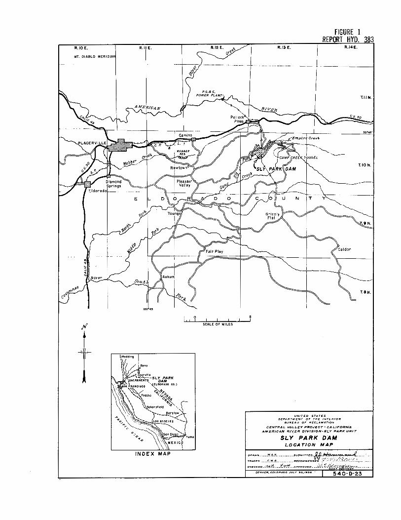
Sly l?ark Dam is located on Sly Park Creek in Eldora.do County about 12 air line mUes east of Placerville, California (Figure 1). The principal construction features are an earth- and rock--fill dam, an· ea·rth- and rock-fill dike, a concrete-lined spillway on the left abut· ment of the dike, an outlet works through the dam, and the Camino Con-duit (Figure 2). · ·
The spillway will consist of an uncontrolled overflow .c,rest, a channel with a roadway bridge across it, and a chute whicfr terminates in a shallow ski-jump bucket. Hydraulic model studies on the spillway are reported in Hydraulic Laboratory Report No. Hyd-370.
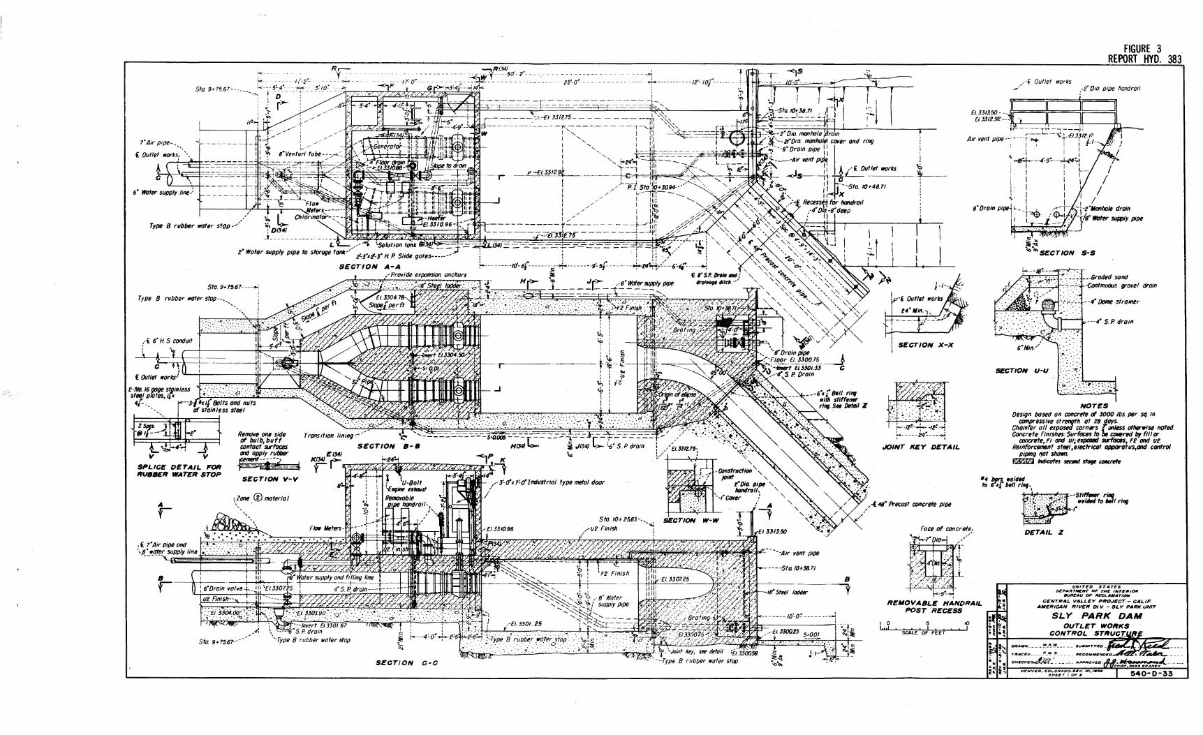
The outlet works is contained in the main dam and will consist of an intake structure, a 48-inch pressure conduit, a gate chamber, a downstream conduit containing a 36-inch steel pipe, and a control structure (Figures 2 and 3). The control structure ·will include a· bifurcation, two 27- by 2-7-inch high-pressure slide gates, and a stilling basin. The difference. in head from the maximum reservoir elevation, 8476.15, to the center line of the 36-inch conduit at the basin, 3307. 25., is 168. 90 feet •. The elevation of the high point of the 48-inch conduit downstream from the basin is 3341. 05 which submerges the basin a mii:iinium of 33. 80 feet. · ·
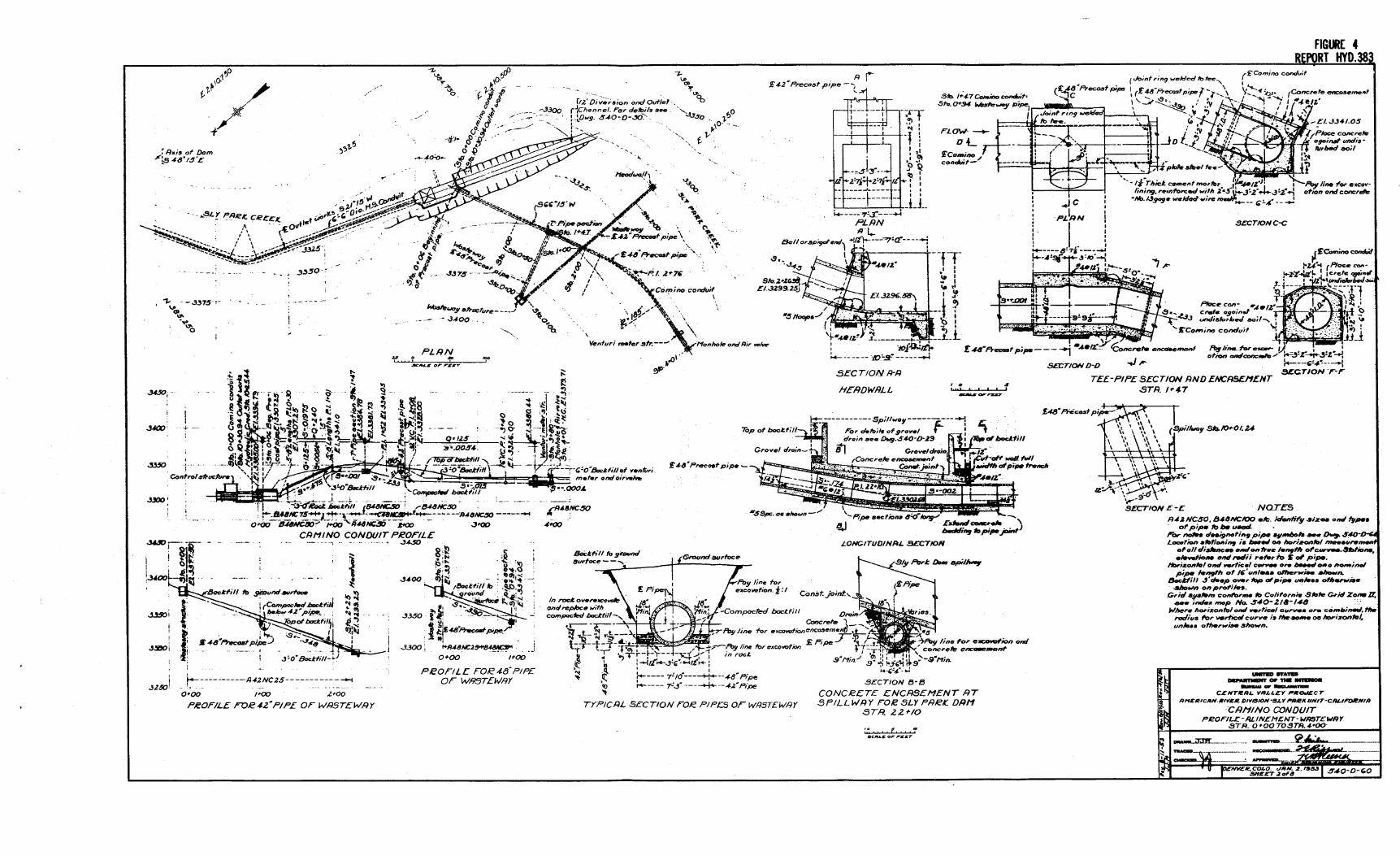
The Camino Conduit will consist of approximately' 6··miles of concrete pipe and a number of appurtenant structures, includlng· a Venturi meter for measuring the rate of flow and a wasteway for limiting the conduit head and discharging any excess waters released through the outlet gates (Figure 4). The wasteway is about 147 feet downstreaitn from the stilling basin.,..and is on the side of the hill above the basin structure. · The wasteway overflow crest is set at the hydraulic grade line for the normal flow of 125 cfs (Figure 5). If the outlet gates are inadvertently opened completely under maxi~um reservoir head, a flow of 240 cfs will occur and about 115 cubic feet per second will be wasted at the struc-ture. · · ·
The preliminary design of the outlet works stilling basin included triangular-shaped baffles similar to those developed for the stilling basin of the pump:-turbine bypass valve at Flatiron Power and Pumping Plant, Coiorado-Big Thompson Project (Report No·. Hyd-328). Hydr~ulic model studies were made to determine the appropriateness of the baffles for the Sly Park structure and to determine the characteristics of the over-au:· design. A discussion of these model studies and the results obtained are presented in this report.
2
Sam Peng
Sticky Note
None set by Sam Peng
Sam Peng
Sticky Note
MigrationNone set by Sam Peng
Sam Peng
Sticky Note
Unmarked set by Sam Peng

INVESTIGATION
The Model
A 1:6. 75 scale model was constructed, and a transparent top and right side placed on the stilling basin to permit observation of the flow within the basin. The observations were facilitated by injecting air or a dye into the flow as it entered the basin. The length and depth of the box incorporating the basin were made greater than required by the preliminary design so that a larger basin could be accommodated if it were found necessary. A false floor and downstream wall formed the preliminary basin dimensions. An ellipticaHy shaped bellmouth was provided for the entrance to the 48-inch (7. 11-inch model) Sly ParkCamino Conduit. Two 4- by 4-inch regulating gates immediately upstream of the basin represented the 27- by 27-inch regulating slide gates of the prototype structure. The model scale was based on the available 4- by 4-inch gate used for the model studies of the Trenton Dam outlet works (Report No. Hyd-300). A second gate was fabricated (Figure 7). Gate and conduit piezometers were installed as shown on Figures 6 and 7. The assembled model without the triangular baffles and dividing wall is shown in Figure 8.
· In the preliminary design the included angle between ,the 'bifurcation branches was 40° (Figure 6), a~d all model tests were made with this bifurcation. Later the angle for the prototype bifurcation was increased to 60° but.the model was not changed because the influence of this difference was considered negligible (Figure 3).
Initial tests were conducted with the model inlet connected to a turbine-type pump {,Figure 6). The inlet was later connected to a constant-head tank for reasons discuss.ed on subsequent pages of this report.
Tests with Model Inlet Connected to Pump
Surge in Flow
The first model tests were made with the triangular baffles removed from the stilling basin (Figure 8). Good performance seemed to occur, but measurements with a total head tube in the outlet conduit (Figure 6) showed a pressure surge of about 5 feet, prototype. The surge wa.s approximately the same with either symmetrical or unsymmetrical gate openings and was undesirable because of the possible interference with pressure measurements at the Venturi meter and because it might cause unnecessary spilling at the wasteway.
The triangular baffles were installed in the basin and the test repeated. Pressure surges occurred with about the same average magnitude as without the baffles.
The source of the surges was obscure, but it appeared that it might be the turbine pump which was directly connected to the model by
3
Sam Peng
Sticky Note
None set by Sam Peng
Sam Peng
Sticky Note
MigrationNone set by Sam Peng
Sam Peng
Sticky Note
Unmarked set by Sam Peng
Sam Peng
Sticky Note
None set by Sam Peng
Sam Peng
Sticky Note
MigrationNone set by Sam Peng
Sam Peng
Sticky Note
Unmarked set by Sam Peng

30 feet of lightweight steel pipe (Figure 6). The system was therefore modified so that the pump supplied water to an elevated constant-head tank which in turn supplied water to the model basin (Figure 6).
Tests with Model Inlet Connected to Constant Head Tank
Surge in Flow
Pressure surges of approximately 4. 6 feet of water occurred in the 48-inch conduit when about 175 cfs was represented, even though the model was arranged with the inlet connected to the constant-head tank. The basin and gate assembly were subsequently removed from the pipe line and a section of straight pipe was installed in its place. The surge was about 1. 5 feet at discharges up to 120 cfs but became about 5 feet at discharges above 200 cfs. The basin and gate assembly were reinstalled and measurements were made of the surge frequency by means of pressure cells and oscillograph records. No regularly occurring pressure pulse was detected, but over a period of time a number of irregularly spaced surges occurred and the average frequencies of these were determined. With the baffles installed in the basin the frequency was about 1 cycle every 2-1/2 seconds (prototype). With the baffles removed, the frequency was about 1 cycle every 2 seconds. The baffles apparently did not exert much influence on either the surge frequency or amplitude.
The above tests were conducted with an outlet conduit which had no vents or standpipes between the stilling basin and the downstream control valve. In the prototype conduit a standpipe exists in the form of the wasteway conduit and box (Figure 5 ). The water column within the standpipe will be free to rise and fall as the surges occur in the conduit, and in so doing will. moderate the surges. Relatively small rises in the standpipe column will be adequate to provide the storage, needed during a pressure rise, and conversely, only a small decline in the standpipe column will be sufficient to smooth out the rarefactions following the pressure peaks. To determine the moderating effect of a standpipe in the model, a 5-inch inside-diameter pipe was placed on the outlet conduit 6 feet downstream from the basin (Figure 8}. The surges decreased considerably in magnitude and the water level fluctuation in the model standpipe was only about 1-1/2. inches (10 inches prototype). The actual field fluctuation should be even less because the standpipe area at the overflow weir is about 3-1/2 times that of the conduit, whereas in the model it was only about one-half that of the conduit (Figure 5 ). The frequency of surging decreased to about once every 9 seconds, prototype. It was believed that neither the magnitude nor the frequency of this minor surging would be troublesome in the field structure, and no further model studies were made on it.
Head Losses
The loss in head through the gate assembly and stilling basin, measured from a point 1. 13 feet prototype above the bifurcation in the 36-inch conduit to a point 4-1/2 feet downstream from the bellmouth in the 48-inch outlet conduit was determined for a range of flows embracing the normal
4
Sam Peng
Sticky Note
None set by Sam Peng
Sam Peng
Sticky Note
MigrationNone set by Sam Peng
Sam Peng
Sticky Note
Unmarked set by Sam Peng
Sam Peng
Sticky Note
None set by Sam Peng
Sam Peng
Sticky Note
MigrationNone set by Sam Peng
Sam Peng
Sticky Note
Unmarked set by Sam Peng

of 125 cfs (Figure 9A). Tests were made with and without the baffles installed. Lower losses occurred with the baffles removed.
The loss from the stilling basin through the bellmouth to the point 4-1/2 feet downstream was also determined (Figure 9B). Slightly smaller losses occurred with the baffles removed.
On the basis of the above head loss data where smaller losses occurred when the baffles were omit_ted from the basin., and because the baffles had little, if any., moderating effect on the pressure surges in the outlet conduit., it was decided that the baffles need not be included in the prototype structure.
Pressures in the Sly Park Slide Gate .. The pressures on the sloped and horizontal bottom surfaces of
the Sly Park gate leaf., and on the right side wall of the downstream frame near the gate floor., and on the· roof of the conduit downstream from the gate were measured at gate openings of 10 to 100 percent (Figures 7 and 10). In these tests the flow was confined to the left branch of the bifurcation in order that the rate of flow through the gate be known. The lowest leaf pressure was found on the horizontal bottom surface near the downstream 1 edge (Piezometer 4). The lowest wall or conduit pressure occurred just downstream from the gate slot 1. 7 inches (prototype) above the floor (Piezometer 6).
The pressure data for these two piezometers are presented in 1 the nondimensional form of pressure coefficients (Figure 10). This presentation was adopted in lieu of presenting the actual pressure values because the values could not be accurately determined at the time of the tests due to uncertainties concerning the conduit back pressure., these back pressures directly affecting the local pressures in the structure. The pressure coefficient is defined as the difference between a reference pressure and the pressure at a given piezometer divided by the velocity head at the reference station. The reference station was taken in the 32-inch conduit at the end of the bifurcation branch., and the reference pressure was the average of the piezometric readings at the inside and outside of the bend. The pressure data may be used to determine the minimum pressures which will occur on the leaf or on the frame of this gate in this or other installations with submerged flow and known upstream and downstream pressures. In the case of the Sly Park outlet works, there appears to be no danger of cavitation occurring on either the leaf or the frame of the gates, or in the conduit downstream.
No calibration curves, relating the discharge with the reservoir head and the gate openings., were prepared for the outlet works because all flow measurements will be made with the Venturi meter at Station 3+80 in the Camino Conduit (Figure 4).
5
Interior - Reclamation - Denver. Colo.
Sam Peng
Sticky Note
None set by Sam Peng
Sam Peng
Sticky Note
MigrationNone set by Sam Peng
Sam Peng
Sticky Note
Unmarked set by Sam Peng
Sam Peng
Sticky Note
None set by Sam Peng
Sam Peng
Sticky Note
MigrationNone set by Sam Peng
Sam Peng
Sticky Note
Unmarked set by Sam Peng
R.10 E. R.I E. R.12 E.
0
SCALE OF MILES
.Jr.
INDEX MAP
FIGURE 1 REPORT HYD. 383
R.13 E. R.14E.
UNITEO STATES DEPARTMENT OF THE INTERIOR
BUREAU OF RECLAMATION
CENTRAL VALLEY PROJECT - CALIFORNIA AMERICAN RIV.ER DIVISION-SLY PARK UNIT
SLY PARK DAM LOCATION MAP
OENV£R, COLORADO • .JULY 25, 1952 ' 540·0·23
Sam Peng
Sticky Note
None set by Sam Peng
Sam Peng
Sticky Note
MigrationNone set by Sam Peng
Sam Peng
Sticky Note
Unmarked set by Sam Peng
Sam Peng
Sticky Note
None set by Sam Peng
Sam Peng
Sticky Note
MigrationNone set by Sam Peng
Sam Peng
Sticky Note
Unmarked set by Sam Peng

DAIii
Clt£ST 11..E'IIIATIONS wtTH CAMIIE'R STATKllf "°" , .. .011 GENERAL PLAN . ..
• '117 JOO 0 IOO 100 . .DD
I • ·"" $CALI Of ft:t:T . .., •OO - .JI .. o ~- .00
-Sta. •r•~ SIii. 41•0().. Sta. ~•ot>-.•
-~.'1!~5-lif2&J~;--····Cr,sf w· llol,l--,[lJ4.82.0 as
0.0 - ·- 0.0 u ~
CA"1IBER ON CREST OF DAM
••oor,; Crtsf Cl J48t.o-·,;,. -"=r•oo - ~,~----- {Original ground lllt'faa /--;.-:.;;,;_?_'-i~,,,;._ ·-. Concr,t, grout cap--- --~ ____ ,>.---r-.._
I lij//Jr~ · , Assumtd surtac, of ••• -"\ \ /; 'j// ··-._tirm ,.,a,,,.,.,drotk····. '£1f1nd_grout
/ h ',, SLY ,,.R• curtain upbofh / / 'Grout holas (ii •, cRllK, a/Jutm,nfs as
~-:':"'· ,:.__=__or less ',,_ dimted.
·-3'00 3300 3300
3.00 .. 00
STATIONS ... 40
PROFILE ON AXIS OF DAM
\to 4 ., . . . :t_n···. ·- "TT
1·#, 6' Cr,oS()/t fr,oftd fimb,r past----··--- : us. c,._3.:7:.~o-··, ____ _ *'- 11S. Cl .Hlf. 15·)_
£lJ462~t
DIKE
Camblrld crost--•• Slo.16•J5., Hifh,,., Sllbgrtlt#-. -·Sfa. 20•40 ••• i 5/D. ,.,15.__ :
of :Sia 11•40 \ ~ ~ : i"C1•1.0-tll/00,025L: -"'1~' :1, i---'i•LO·Q(l!lq025L:--•1,-'
~ :bFi:f:; .iL t.J412.:-·l".?tisJ::~ ~ . ~
CAMBER"ON CREST OF DIKE \P··-{Spilhloy
··:Crtsf Cl. 3482. o 3500
~------[·Ori9i1111I grOlllltl surfac1 _,-:;;~ ----. Ass•,,,.., surfac, of firm ____ ''''iiiJ1"),
1111 ·----~fhartd rod- •• _,-- \\\ _ • .;.;, \ I I 111; -.. _________ \ \ \\\\ \ '·£,fend grout
I I, . : \ \ \ curtain up I /" Concrlft grout cap--· · ), \ abutment as
'Grout holu ti .,,,,-ox. ,o' crs. or less/ directed
••oo
3300
STATIONS 20 ,.
PROFILE ON AXIS OF DIKE
1"'··-----100· ...... ___ ,---····--·-1 ----:....-lirot,1...,,,_,._,o'ers. orlm
11'AXIIIIUII SECTION-DAIi - A-S A#O - P"LY n, OIKE
---~-----------°"-=------~-----------¥.:.·--OrifiHI;:; OF FEET
_____ ,,,.. .. 0 .., N)O
IOO
SCALI Of' fl:ET
-~~----::->-----Stit !0•15.oo-..., ~----- .-£1. JJO,i.00
c-ilo t:IHldlli#-------... ~~3295.J
PROFILE ON €-OF SMLLWAY 0 ,oo 200
f-···A•is of.,,, .
r-·:-:·::::;::::..J~.:::.:.:::;:::::;: , .. -Gtln_:::::;:IS-4" Road surlacing----~-.: -·-sloti,},iirffKll-·a 4 ..- ·_.,.-.,~.iftlod
. ~. ~ '* NJ' . __ _i_ ' ... s --,,.-!t.-,:.& '5-
5,.!, •.i .. - ._.-.~... _r_ Cllllll#rELSUt.O 1 , • • .,• #•O.P,, _ • - • -
-···S. ...... .,.,,,,.,,.,, __,.;-- Lit:/
-·£13"2 .i.
CREST DETAILS AT WAXll1'Ultl OAIIIIIER ., Crest c,. J•n OO···-•
\._~
I t'·-Grouf ( I ho/IS / ... __ .J.
Anchor bars-'_, I
0 .., ID
SCALE OP FEIT
' --' .... q,1,:-_~---Cllfoff c.i111rs---':..~~· : _____ ,_,,.., ------~?.r:a:r~:J
2-o _,,;_,... 2'·:t"b.J
SECTION THRU SPILLWAY CREST SECTION A-A
(1/psfnom COtlllitl SECTION B-B (Downsfr,am a,nduifJ
£ Intake structure Sia 2•11.00- ••.
Sill fl 3350.00· .:·"'I Invert fl JJll.0-, ~
Sta 1+2150···-·
.__A,is of dam
Sfo. 5•5B.OO- ,-Gate choltlw '. : 2c,•,2'-,"H.l'fJllfe
____ Origin~~~d s,rfau-, ..,.. •• ,, i B ___ _ ----- --------L ... --1',-~----' ._
, • -- f·O,t .• ! ! Ii I 4-o w : L>--. 1/.f-io..s1nontcan<*lif.-· - .. , , ·, upstream conduit-·' A I ~-- I ..J J6"1D. lltlfaf p;pe--'
Dom grout caps,· B PROFILE ON ~ OF OUTLET WORKS
Control strucfur, 2·2'-J", 2'·J·H I' gal~~'
,:_·;}i!~<!.<!!~---...-...a.:r=--i::r:r:r::J :'t--.5ta 9•1.<.57
In•erf Cl 3304.00
FIGURE 2
Firm rock--·
tJ.-ndingonllOhlf'ld _..,; ·.·:; ;:· ·-,fOia.groufpipt J'llin,llaz.osdincfetl "'': ~··· ,. •
rod111<D1111,.l'ld······· i .,·,~ :_.;: tmbffdtdin
. ""'"''' 3' Min t 1-:,r·tl;..-i -Grout ho/ls ti J'li"ArJ ····--·· • __ , .,,rtJI.IO'U'S.
CONCRETE GROUT CAP
EMBANKMENT EXPLANATION 0Sac'-d sil~ c/11. slllfl.wrrffll-"ffd t, '-inf
ra/1,rs n, 6-inc/l ,.,.rs. ©s,1ect,d rod fines .,,,,,,.,ctd "1 cr,wl,r t,,, tro,tor
fa 12-incll loy,rs. (i)Rod fill p/«ld ill J-foot lo11rs.
RESEIIYOUt ... ,. IN HUNOIIEDS OP acat:s 0 2 4 5 I to
ltlstltYOII CAPACITY IN TIIOUSANOS 0/F AC.II£ f'££T 0 ~ ~ ~ ~ ~
HOO
,_,I I I I ~~= I I
• .. S~ILLIM1' DIKNA .... TIIOUUIIOS 0, C.F.S.
O t I I 4 S OUTLET-OIYEasrOM DtSCN.INC IN-- 0, G.f'.S.
AREA-CAPACITY-OISCHARH CURY£S
RESERVOIR DATA *Irrigation sfara,,.H,5tOa.t £1.JJSO.O *' c1.J•11.o *0.ad stor191 .••••••••• 4MJ at CtJJ/lt *' Cl JJ50.0
Rtur,oird,sign flood lllill1Je11ns.tlillith11H1. spiffwar disc/larat of 6100C ts . .,,, • .,,,,,,... o/ ,lfma.t /o[l-.lS
*Capac,tyo141,000a.t from s,,.,.,,._ ft,.»12tJ lo B.J•no incl•d,s an affallOtlCt at 1.000 ,.t for s•tli-t
11Mr£o STAT£• 0£PIHfTM£#T 0, THC l#TEIIIOII
•ull£AU 0, ltl!'l!;t.A .... TION
CENTIIAL VALL£W' lf'lfD.IECT-CALJ,OlfNIA AMElflCAN It/VEIi ON. • SU" ,.All« UMT
SLY PARK DAM GENERAL PLAN AND SECTIONS
t:H£Cl(£th.4VJf.. _ .1('_~~ .. --avEO. _
OE~lt,COL.DlfAOO. OEC. s. •ff2
Sam Peng
Sticky Note
None set by Sam Peng
Sam Peng
Sticky Note
MigrationNone set by Sam Peng
Sam Peng
Sticky Note
Unmarked set by Sam Peng
Sam Peng
Sticky Note
None set by Sam Peng
Sam Peng
Sticky Note
MigrationNone set by Sam Peng
Sam Peng
Sticky Note
Unmarked set by Sam Peng
R,--
Sta 9•7567------- ::, 5_,_(-~-_'!;/'_ 5'.I_Ou Y;..,-_ --,,._ , D
r>-
7• Air p,pe-_
' -==:-+--------- --12·- ,of'-- -
--:---;~ =-~ --~ -=_c _-_ -=- =- ~__z.--=-~=-~:_~~' 1·~' r-- -----:..=.--£/ 331215- -- - - - - -- --n, '<,, __ _f:.,
---------------is------ - --,-"'-HI ',' ''la'~ I' I I ';,~-,-----r -
W " I 11 ~-=-=---t- --1 ", I 111 I I "- I _ui I
: '-.,, . -f~jjf~~---=---=-..:-,,;~==¾"==-~ I -. :-0-24"~ ff -¥11 L--;----
-;t-,--1 I
1-::1 · -... I
I
'\::,
FIGURE 3 REPORT HYO. 383
_,,,/ · f Outlet works .,2· 010 pipe handrail
El. 331350 - -·1 . . I El 3312.92 ---~ "t II II I
----.,H----.---,11 r--'-·-··,¢,_-t_.ElJf2Jj __
Air vent pipe---·-··;-~ i I z·
; I I I • !,.i ~ .-fl~--4~9~---,.!-<24 I
I 't---7 ii1\ o/' - '- ':> /2'-> y--£133129f ______ -+-e-1,_.=-ittr~ ~--..x..~
I ! I LI ~~~ -, -. ~ -------"/~~--
. I I L--1 ; I
, I I I I I I
6" water supply line)
,
Type B rubber wuter stop_.,/ •' l' ~ i)o: 0($4/
-*------------
Sta. 9, 75 67-----~ I
Type 8 rubber water stop--_
-------._
,·£ 6' H. 5. conduit
_l_-L :. \ : C
2-No. /6 goge s~inless l·:_:_:_:_: :: :-'-'. '.;i; ._. ___ : _ steelplofes,li:c .· .. ··-.--.·-·. ---···· 4{- .. r--·3f ,,{ Bolts and nuts
of stainless steel
-~~--~~ ...:, V V
SPLICE DETAIL FOR RUBBER WATER STOP
A
Remove one side of bulb, buff contact surfaces aid apply rubber m:1·1 , SECTION V-V
;Zone ® moterio I ' r
J~ !!! .• .• .•. eb ... ~·1>·~
••• 0 ....
. £ 1· Air pipe and \ 6' water supply line ·------.. ™
B r
I
I / I I 111: : ,,/ I I~ ' / : l~t\l I, __,..-!-11: r-----------r 111:
- - - - --- ~---El 3fi2 75 - - - - - - -""""7--'f: ,,. • • • ' I ~
1111 llOll 11~ --'
~,p K -~~~
....
~ m}~ ' -<:: : .: -~
·t-~-~--' .... ' I -? i : ro t i
:j,f;~ y ~iii= ,.-3:o-,1:<11ndustriol type metal door
/
,I
Sta. 10f25.B3--. -~
-~::·'i1}J0:.Mnrt-:-_·\?:f:.?-~?-~f:-~~~:·_tt_;4.J.~1--\ f • --~ :-::_-,~~e~·fElJJOi.61··· 6
• •• ••• /,· --:-· • ••• •• ;. • · ·'Tl\Jt:~t .--El.3301.25 , ,... -~,_ _--j __
Sta 9+75.61---
\ ~_.__.~"SPdrain · b : : ::·~-~ . .:-: .' .... r. ........ · ... ..,. Y 1-..,;:_,_ --~ __:_·.-· t?--~ '··Type 8 rubber water stop ~ t<---4~0~-o-:---£!6 •_ ..z!i;!~: >Type i/ rubber ·wafer st~p -
~ : •. : .· ._·.··.... . ·.,,. : -.'-:Q· ..
SECTION c-c
" A
7 " " "~7tl}:~ - ·---Air vent pipe
- --- -Sta 10•3B.71
B --------:,
y
-- ---- - ,o~o~ -- ------_j --El 330Q25 5=0.01
~"' J. -=-=-~
--,T. ,a-,.s .... ~
-~:K
l!::« ~~
4\!. le;
~,1-~~r-~~
--
I
±.t I I
' I
'
~--12!-+-,~~ ~-----24~---":
JOINT KEY DETAIL
I: I I I /
_ ~
1
I .•.. -j--. _!_2 .Monhole drain _ s· Oroia p,pe1 k -}-~ .'~ ,: ·-}.Atwater- supply fJlpe
'1·.-, .. ': _, • _J -~·~-.-,:,,,-;_
:IE~ "' °'SECTION S·S
-.·-.-----, .... ' ;,-..,~,-,-c--11/_:-. ~ ,]---Groded sand
-Continuous grovel drain
--4· Dome strainer
,---4• 5. P drain
' 6"Min_.,/
·.• .. ·.:.
SECTION u-u C:: _:ci:
::.~_: ·:_::---~--~-;~~:. ~} /~~
NOTES Design based on concrete of 3000 lbs. per sq. in.
compressive strenqth at 28 days. Chamfer all exposed corners ( unless olhtlnrise noted Concrete fintshes: Surfaces to oe CDllered by fill or
concrete, Fl and 111; exp(}Slld surfoas, Ft and ut. Reinforcement ste8I ,electric/11 opporotus,ond control
piping '!(It shown. ~ lntlicotn s«ond stog, ctltlCrrt.
••~welded to 6"•, bell ring.
I
A'. 48" Precost concrete pipe
--Sti"- ritlf ••ltlH to be1 I ring -,· ,
REMOVABLE HANDRAIL POST RECESS
I 0 l...J...!
5 L...........
ScALE OF FE ET
10 J
DETAIL Z
UNITED STATES DEPARTMENT OF THE INTERIOR
91.JlfEAU OF RECLAMATION
CENTRAL VALLEY PROJECT - CALIF. AMERICAN RIVER DIV. - SLY PARK UNIT
SLY PARK DAM
CHEC,,C£~_ .. _ ___ ._. APP~VEO.
DENVER. COL.ORAOO,OEC. IO.IIHI~ SHEET I OF~ 540-0·33
Sam Peng
Sticky Note
None set by Sam Peng
Sam Peng
Sticky Note
MigrationNone set by Sam Peng
Sam Peng
Sticky Note
Unmarked set by Sam Peng
Sam Peng
Sticky Note
None set by Sam Peng
Sam Peng
Sticky Note
MigrationNone set by Sam Peng
Sam Peng
Sticky Note
Unmarked set by Sam Peng
,., -z..
"'<:P ,.. .A
7- Rj y; 42 "Precosf pipe - (.
( .Joint ring welded to tt.e..__
FIGURC 4 REPORT HYD.38
('£Comino condu;t
'--..:. a,/1,p
t,1-·
.,vJ. ~.
r12' Di;,;,,.ion ond Ouflef·.
"""",,.. ·-,.oo
dchonnel. ro.r de'IIJils ,,_ ·, o
I ( £ ~-Precost pip,, f ';- \ Y, -e ½,• (Concrete encos~me,.f .Sib. ,.,."-7Commoa,nd,,__it• \ ,_::;.. ,s 0 _ , ---... • .: -~ 4 .-..,.
1 .,
4._,
1,-
5to.~:u ~'""'p,pel.-.JII--~--,,-, ' ~ •' N.::,-;Li•"'-'"'-- / tf ,· ... ( .. LQwg. -5-4-0sO-JO':·. ;.J3_,.o .. -,,6 I ---~- ~ I ~
-+ ,,if>
'· I .. O· ."-... f-- . 1r' ~ -- t- 'I,•
(o .,,. "Y. -£1..J.341.05
1 1------,H /; ·:'I' . • 'I/Ploce concrefe ---41--+_Jo - . .I' ... . _../!J. ogoin.,f unditr
r /:bis of Dam "''i.s 48" 1!1·e ..+-40:.0-
-, ... · '-----H ---,,· . . . !.• 1/Jr/,ed 80i/ £Comma/ _ 1 '· ·•· ..,.,.-.:..1..-, 1_-;-t
.... __ ..,.1=,-__ conduit- F--7F=Jt,;::=l::~F=i ~-,: , fptofoll!!el ~e- , J.r
ll2!+-Z;~j4""Z! ,• ',. • tJ" Thiel:. c_,enf mo,11,r I'1-.-11,•J, 'i----R>;s, line 'For excov· "'~
, . •"'-f PR , . • •'" - ..,.;t
~ ..... .e1:.c.e 5 ~1!"J~a>'-:.;..--:. · CCI( • · ,JC.& • - ,a,,../___ ,:-
' % ~ . ...... -'----- - , lining,r•inforced with ~l+..3!z·..J..,3!z"+J of-ion ondconcrefe ---+---- - : ,.IC ! •No.l.J!JO!J• welded-wire ~-- ~~,.· __ ...J
; _;\ -. ~~o"*'"~-~J:::=>-Y ......... ::~~· ·- / \ _'; --~:.-~-<-· .. - '
. ----: :::-;. ~--:----"<f.3z5·: ' ... _ _ ____ .... . j
. (f'q
ll 'l- .. -.3.375 ,
~O>
"' . ..,. ~
.3450, ..
.J,400• -+-
33!fQ · ~
~
~(: .. ,.~
PLRN acl'tLe orre,.,.
...... _
"IO
. i "' ~ ~ 1"" , a( ~ •J ' ~ ~ l g .,.. · , -o a- - , ~ - ------·- -- . .~ . u '& i,.; , ~ .., ~ ij .. ! .. I t--= @ :e:~ ("' ~ ~ : ~~ i2 ~ l 8 .. ~ t~ ·- d · ~ , ~ i!lc) t,: ~ t; ~If ...: ~ 'ii ~!IS O i ·~· .~ () i <t ~ ~ .,~a .... : ~ ~~ ; N 1:~:1111 1 o ~ 1i · ct~ O O> _IQ ~'i.,,..O •··o· ~'t. 't ej "1 1o ,,._,:J · · - - . ..") 0- ..,--~ ~-..., ~ Cl fl") In,- .,c-., ~ ,t Ill u,. '--\ uo ~ ~. , _ ~~~111, ">-. "' -- • ·S.:"' Q• IU "'::: ·;:,:,l;_
'"50 4:Q~ iii 1!~ ~I~~ ti ~ ~t} ~fop:,;:::,~"' ~~ · . ~~~: O)li~I l'-.:.f~ 1- • ' - ----- • ·,----.\I-· ·-tT--·•·-• .. -· '• 1"> 1 • ·-; · 0 · ·- _ , S. '..3'0"aockfill ., Y ·--i--·<;!o·~uitlof. 11•nliJri
' ·~ 1' I I • 'i-'-f t1 , r4 , f!r .. 00/ -s-~ ,;--t~--'="" -· -. meter ondo,r.,.f,e
..3.JOO:
.... . ,r, 1/'-.,,. , ..• ,,._,.,.,,, ~ ... ooo• I L..L.....L. • '.,,.,... ~"() __,,,,., , '-Comp,cft,rl bocl:filf ,_, •-. ""
f • I 1 1
.... 11 • .,.
(\
~"' ',~""
£ 46'Precoaf pip•-
SECTIONR-R
HERDWIUL I 0 .....
~--rzzr
,S I
I
' l -- 3~ ic-;i-;;, · iuaNC4li' ,,-846NC!XJ : · -- -- -
, ~-~!.~T_!~_:t:~,--:-:-~-~~-----~---R46NC.50 ------+I . . 0--00 8-#NCllO'."' l-«J IU.6NCSJ ,i,oo J-00 4-00
t;R-'BNC!IO ""4,S,oc.a11 eho..,n-.,, \_Pi-;.~:=~1~~,tn:;;, 1.-··$ ---8 I £,4e,,,/ ~ \
CRNINO CONDUIT P~Or/L£ -"""',----i i if!
; .. ... .. .34.50
! . () ... !.34001 .I!!~ !'"1)!~.
~und 41Url'oce
; rCompocfed ~~'Ii ' i!>-Ji:,-,, 4,rp~. ' . ~I
I I I
..,.31:lO i ~
-..__ ~of bacA:filL: ' ,- ~ ,,
f6,4.8"f"'r«:oatp·j ~ -s~:~ I ,pc '""'~
.• -·- _ _Jr
.3•0· Boc1:,;11-u
l ~
le)~ ''hi . "' ~~ .e,;:-: 111,,,.,,
I I
.3250 _ ~~---------R4~_NC2S-- ~--~~.-~~--=-~ 0•OO I~ .l.•0O
F~Or/LE r'0/24,Z"FIFE or WRST£WRY
J400.
C !I! ·l.:~
• l)O)'-..: -~·-. ,!ll:),O) round · Q. ,">
-~--'i:.../i!·-.; I ~- 11):i..i
;,,, ~. I'· .3.350 ' "'~ .. ~.---':5· -- ' :& (Ji • I
<II "!.. . ' J ~.o,48/?wcoafpi~ '
J.300 \ .. ll46NC25"'"8~ -o~oo l•OO
Pl:Of"/Lt:: FOl24-8"PIP£ or WfoTEWRY
~ bedding a, pipe joint)
i.0NCITUOINRL SCCTIOR
£Pipe I __ .. ·-"- Conilt.join:t, ~ { ,n r~overeJICO'ltl'Vl'IC' ...... , • ( ondreplac•with ,. • ....,-~ . ·.,,. 18'\,
compockd bocJ:fill--, -""'--+-.i...--Compocfttt:I boct.f,11 Oro;,, • .-·;;.-· Com::refe 1--"';. 19' ~t.- ~ .,t.___ _r-FtJ!lline -for excovofionenco.,emenr; ·J;-~ *'-·~-i--f-!L,;,c _ - · · . . ii PipeJ'1!1_f;--· -}l'by line h>r e-1/fdion and lT-:1° J •a,
1 , ,'I\ ,, -"'.:r-Fby /me 'for e1'.cavof,on 'I' ·r-- - , .~ ,
\l T , ·+r-1---)--- -"--( ~,....--r in roct ,. 1 -,T~r: , concre~ ~ncoee1111enf-~ .. ") 1 •...r , .~ 1 I o",..,,· .,I O') 11 1 Iii ..,_ • •
,it. ~· : -+-lu .,._J., ·+-<7£t+: .., , 11n. -9• ~ !o,i~ ~9· -s Nm. ~ · I , • . I • 1,+~.!4" • .J 't , . :----- 7·/0------+-";+---·48 Pipe
~ .----- 7:,3•-----4+---,4.,z'p,pe SECTION B·B 't. CONC~£T£ £NCRS£MENT RT
TYP/C/:/L SECTION ro~ PIPCS or WR5T£WRY 5FILLW/:/Y roe 5LY PRRK. ORM .STR. 2.2~10
9CltL£ 01'" 1'"£~T
• I I
SCCTIONC-C I
I I
l, PL,'RN ! I I
: • ,. I .,.,.. __ • --~·• o+-----8·7i; ___ _, ,,,,__,,,,noc-, ...,,,.. :-u~ rPloce con-
r-~t'¾l-.J. ! Crete 'll°''!r, • • I 2 i'ondielr,rl,ed -.to,1
~_i-_-;,-_, · , ··· •. '"~\11 Pfoce con~ ,..-'•tz• · • 5)- ,:: r .. ,' c,-fe 0.90,ns/ ..-*'lr--#- ¼ ~ undisturheJ aa;/, , ),"J . ~·=-·.. "'2 '-'
'-. • • "' I .~_:'.; "'' : 11.Conn,no conduit • , · .. ,.·,.,.', ,.,, .! _J,( •a,._- .. ., .Jj_ ·~, I
/iJ:y /tnc .for e_,,. V, • 1 0 • I
ofH>n Olfdconc--' l+,;;3-r-...,...3-1, :.+! }+---c;.:4~--~
SLXTION O-D S£CTIOH ·r-F T£t:-PIF£ SECTION RND £NCRSEMCNT
.STR. 1~47
\ \
,~,,_Y s~~o,.u
~~,z:,· ).-~~
.ct:Y"'"\''\~..;,\ .. · ...... -9 S£CTION£-C NOI£S
R4.1.NC40. 846NCIOO eit:. idenfffy-siz- ond type• · of pipe lbbeu.,d. l"&r no1We d-.ignofing pijl» avmbota -. 0..,. .S:40· Locofion a,Otioning ie to..w °" horiJNN>,Of ,.,,,...,,,.,
of'o// tli_.__ .ndon'froe !•n,fll ofc,,r-.~iona, e,-.,.,;o- ond ,_;; ,.,,-, to Sa, pipe.
lfori11.onfol ond -,ficol .,_ ore be-.1 -• ,..._;no1 pi~ length of Jfi' ""'-• on,,.,.,;.. ahown.
lJocl:fil/ ~·de•p o-r"'i,D dpipe unt.H o"1.,.,,ia• -sht>.,,n onpro,i/es. ·
.Grit/ •r"-m cont'Dr- I,;, Colifornio Slote Grid zo-U. - ind•• mop No. .!T40-2/IJ-/48 ·,_.
W/»re horizontbl ond _,ticol curve• or• combined. fhfl rodius for -rfical c:<1rtf• is ,,,,._,,,. oa horizonlol, unlrua ofherwM ~hown.
UNlnD lll'A'ID --na-......, • ....,....TIDN CENTteRL "'ILLEY ,-,eo,JECT
RffElllCAN./,tllE//l 0/ll~ION·SLY-l!IC UN/T·CRLIFDl/!NIR
CRMINO CONDUIT
Sam Peng
Sticky Note
None set by Sam Peng
Sam Peng
Sticky Note
MigrationNone set by Sam Peng
Sam Peng
Sticky Note
Unmarked set by Sam Peng
Sam Peng
Sticky Note
None set by Sam Peng
Sam Peng
Sticky Note
MigrationNone set by Sam Peng
Sam Peng
Sticky Note
Unmarked set by Sam Peng

' l : -, D •
r'f- ' : , -ti 11 .J D ~ I I 'C
: ·~ i I ., '6
• "> .. •• I -.""'l
C,ofin.9 .$ecfion~ in w,"dfhs c~nvenienf 'N!>r hondliny
IG t---,s',4"-->-1 ~z'll"+zc,,·..J :..µ'(;~l.,_ iLoda&r rung~•lz" I I I/' : i ::::ci$.:._, :·----:,--r
48"Preco,sfcu'-rtpipa,_1 ', ib ·'
-f~~.
.... ' '
C:
,"i. e,p~ent1-----._ R ',!._t_ _________ -::l
stiffe,,., ring if ..sfructl,re is_ con,,~rucfed prior fb loyin9 of jor..:osf pi,,., -..._,
\
::».-: ...
£in,. ring,.>;. ·- •., ,J~
flGURE 5 REPOftT HYD.
~ ~-~~inw°"" z• A ~ • 1 ---:.:._ ~~ J 1 ::r_::-x.!H ____ J
.. =------~ I .- . - r ·I , t ,r_r~o··.v,v.n_-hlrl~r ~
\imt ---- ·0~~~ou,,o'fb-4'o·~- -- --- ___ _! ~ J
JCJINT RT -STIWCTU.e£S
.. ~ : -~L 111 ••• , ~--iH.->-
: I U: L~----' I : I-: ----~-~--? j ' I ~,S-.,:i',
I I I ~41 -f:/./;Dio. venf-..,w,_ ____ 6'-d'----~ :J C
i----- s•i;·-------4
PLRN
t-1-HOO/fM•II." .s J I • __ £ct . .J.Jaa.os
,E 4l" Precoal" pipe -rl.OW
, 0 .s It I l I I I I
.ecl'IL6 OF~IT
,r ,:z-o;.,.·.,,.,.,._ __ __
SECTION. r·r.
i
r M-,!J~"-Uio. -1 i :.z.• .,-+z!1' ·L, ,-,..,,,. ond
, : 1+-#.0"0.iL---iltfr;... ~ ~-,_c,;_,, ~ ... ~1-;,-~J+\';., .
~--\ a.;,a· Dio;· 14-l.' . i
.,.,,,,.., ~ -"-"I &rnn ucTw,..;,; ,I. -_,_,,_.,,., ,,_
- . II , ,ct . ..J;JUI..!NJ
----
rR,y /in.a '(ow •JU:IIJllllion l"f ond cont:1<.ele
Riy7Tne -tr,,..,_lioiif'LL ondconcr~ J c;_k _
_.....I . - '.ii £4~•.n· v-,,,,; ,...,.,_ -.;p,,z· ._/'or fodder runts
-• Dwg. 40-0-..!l/03 ·sECTION G·C
l'7oor ET..J.rrti. 41 _--:- - -+i " VENTUR.I MCTER! STE?UCIUe.£.
/
1'7oorCl.3'7',II-~
SECTION R-R
rbai'.-zl.J..J'M,t,J,/··
•
1
£LJ3'mSJ
r'8/eT SECTION B-B
______ j_ _____ ,,,-Grorins
---w•-..,. ,,;,-J LL£YRTJON c:,o·,_,~, p;: r-=+- ,? ' ', ':t::c=i tJ -,·-.,p;po
/1 I \ I
_,. ----+- ', --!------~6::it ------, --t r-----
· L ·r !4-~_.tL
.I. 1t•1t·J11----~.zf~t-- 'It" &oring 6i,;:.- --: . Pt. l•f.wek/11,,1. -J &r
.
1-NJ. of 48" -/".J'O's,.lld. moeA. bolt-j,,ecut.,,,_rl _.,i:fl, ,,__ n•f o,rd .,,.;;,,.,
~ ofc:o,,c,.:~iy J I '--~- 1-----.J "Grrll-i°,,,- / ..I ii
SECTION o=D r'LHN..
- . ,..,.,i•.J..!" ' . .&r z1 .:j ~£ >fl"f"l ti:Jo _. Hodr.'ffr. -(l~~' / wn'bolf; baa.nut
~.ni,t • ' I I I 7le : . --,--------- _;~:..CUl"!J"~l2."-Hydroulic s-Jient-_ f
Cl £/.J.3-42.. 7tJ-- -t. . ....... _
·DCTRIL •,:·
-m.1· &, 1•J•o•1:[._ _ ... • ,;t,
,.,_ .z•f·o~.,-- , .T ~-- '.A"~ fr,,o~-~ • '*-n.bo, ,Z.f•i
r'6 4lJ" F'reco.st F"f'#!!
r.111e;;1.,,,lii.s1o.~W'.5'1'"' ,,rcn....._;, .... 1,
11 0 ~ ';t-- a .::,.. ::-N 1 '- j Nollrol ground~_., -·.2•j. Ctt>l"iag rllocl:fill osdirecled ffl/i!!.T PLRN L -L ,_
/
W RST£WRY 5T~UCTUI!!£
.... ""- li I
! '§ ,; /Ti: ii 'a 'lil I "'' i) bj I "t• I
I ~:'t I I "' ,..., ' . -rill with mortar
~ __ J: ______ ' '. ·' --C}5pigot end
'£4~~Prec<>-Mpipe- -90°-,.,p ;~~~--; - I I - t:,-L----• .s-~-""~ _t :1E/.J332-'"0) L-.. L.. .S=:O7/ ;--=-~~---- ~ (~".~ :.ispoce oa ehown" 0
.SECTION H-H
~ ~ l . • . T-Ycr~
• • '!) .... '\o..L 'ft, . .,..- • .rr n-·. .. , r- -"T-~·:-n--~ ':l'o i;;, i--,-...:;._~LL}-..:- __ =s,i ~--
V.t:NT 3TRUCTUI::£
!+-.J.< 7£+l-J!7J---l ~---- 7<.3"---......;
.SECTION J-J
'
. NOT£ ror detbil• of,.,._.,...,,.,.,, pipe. p,_,. co-,. rr.p
abor, ...,,..n ond lofiler runga in precoaf c~' pip• -!1- aw,. 4'40-D-fiti .
INIDlll'A'la --'lia--·- ... CCNTll!•L VRLLCY l"leO<ICCT RHCe ICRN ,e,vee. 01v1•JON•.9Ly ,.,,ll!K UNIT-CALIFOlffl'III
CAMINO CONDUIT •.
Sam Peng
Sticky Note
None set by Sam Peng
Sam Peng
Sticky Note
MigrationNone set by Sam Peng
Sam Peng
Sticky Note
Unmarked set by Sam Peng
Sam Peng
Sticky Note
None set by Sam Peng
Sam Peng
Sticky Note
MigrationNone set by Sam Peng
Sam Peng
Sticky Note
Unmarked set by Sam Peng

•••
Bifurcotion bronch piezometers ----.,,
3-Piece bends---... ',, ~1·~-',< \---- l l
( I. 13' prototype )
2 Piezometers-...... -~ z" r· '.,.._ I -
·,
\ I
·.,. 5.33" I.D. Pipe-''
(.4_74• I.D. Pipe------·:
2 -4.oo", 4.00" Slide gates-,.
~ To Sllpply and venturi meter
5.33" Pipe----,
Wye branch - .\,
---+-- - - -- ---- ----
------------------I08" ---------~--------------------------26 75" ------ --- · ________ .J ' . '
' '
' ' ' \ ,
!' 4.oo· square conduit_,,
'"'~ """) ··7 ['"""· ~ """" '"? r M * 1$1 ~ 1 1
1 --r--·-r--c----------2 I 1 --------/------+--9 1-,l--.; :
MOOEL INLET CONNECTEO TO PUMP
,, Conduit piezometers
I ' __,,,- '-~1.78"1-- ,/ I & "- / I 1 --+-1<".....-i I J 'v-/ I ' l I ,6P·11 j= l I ---t...._ I ~ I ~ !
( 4. 5' prototype ) . ' , ___ 1.00 --:
I I
(1.11" Pipe
FIGURE 6 REPORT HYO. 383
To valve and waste
I '-l_l.. ,.('_.,,_ I : ! -'-- / '¥1", I I t
ffi -- L
I
I - --: ---~- t l -- - t-----111· I • - =' - --"" _ _:__ --, :!l ~ I ' --71---i- : I _,......,...-t '- // I : i.-+- I v Ii
,,<,, " /,': ,, . ,, '
I ' I I=' I ' .. I -......J /' I:;;
// ' I '-.I
' . t I
1-------------------------32.15" ------- - ----- ----------+!
PLAN
,, Piezometers Basin piezometer- •• , r?¼"~ ',, I •
: . .., ,,;
I I I -
I I_ I I I ; I I I I 1 : I I I I 1 : r.J. ____ L.l __ .l_ __ -i __ J
I I ~ L ___________ __j __ L I I :::-
2.67";...- ----Ht.07.. : s
ELEVATION
' I I : ' i :
=' 0 0
~
--. ,.; ' I ___ f ___ _
(Supply
, , -------:--:'---------------s·---..t 1
' ... Piezometers
:\., I .........
-----10,~--,,<----------~ , ' ...... ,\
Pusition of total head tube_,.
Total head tube-, '
r'
' _,.-Constant head tank Stilli114_1 basin/
_,-5.33"1.D. !
MODEL INLET CONNECTED TO CONSTANT HEAD TANK
SLY PARK OUTLET WORKS
ARRANGEMENT OF I: 6.75 MODEL CONTROL STRUCTURE
Sam Peng
Sticky Note
None set by Sam Peng
Sam Peng
Sticky Note
MigrationNone set by Sam Peng
Sam Peng
Sticky Note
Unmarked set by Sam Peng
Sam Peng
Sticky Note
None set by Sam Peng
Sam Peng
Sticky Note
MigrationNone set by Sam Peng
Sam Peng
Sticky Note
Unmarked set by Sam Peng

...
rA '"-----~ ------2, ...1 i ~--.L"o
- H-1 4 I
i I ii-~ ' ---1 I I I ' -T--1 I '
-~ ' I :.-------------------:--- ---- 6 .l" ______________ _..J : _J____ 4 ~ I I
! -----¼ • Square nut : , r ' I
I
f'ttJ't·---QJttl!r pin W f."hole
--t---------+---------+--
' ' . I ' I r----------- ------s::i---------------- ------ --1
A
SECTION C-C
C r>
-8 f : I
8
fJ I I I
I I I I I
i _j_ __
~
"' .., d r+----- ---- ----- --4.000~-------- ------1 I I I f
_..t_ __ ---, I.. mr == =l,w = d
-r~=4--- I ...._ ,. · · ! -• } , , ~--:.- ~ 3.650"----.. I
! l_ __ ~~~=~====:~:~:~:~~:~~------------->{ I
"' g: 0
I ' ! ----- 2" T __ ..x.__ I --- ----------i I I
I I I I I I I I I I I I I ... ::: • I
' I I I l I I
' I
-i--1 I I I I I I I I I r I
·g • ' I
I
' ' ' !
_ _,,
l-0.-750~ 0.250~-j UL: &·o--H r-· :
t1 f I
0.125~---
FIGURE 7 REPORT HYO. 383
T ____ -_ ... I; :z: r-0.291·
~ :i : :;G.03~ , .. e T - __ :lj _Lf--, ,-t-T
0.157~--I 1--• : "': r-0.111 .. _
_ ., 14--0334 ' !
I I I
I I I I
I ' j___j_ See Detail B--'...., /, ,
,,, ,,,: ', \ ,::: : DETAIL A
Flow ----T
: I I I : '§ • : I -n8 I I I I
: (6
SECT ION A-A
GATE ASSEMBLY
SLY PARK
GATE LEAF
:..---------- --- -----5.2&0" -----------------~ I I I I
• I t • I t "'
o.m--7 r-:~===~~:_-::_~~:=-~~~~~~-:::_-::=~-7 r-0297
-r-, ,, :e ? I
j __
I I I I t I I I i I I • I :
!l Detail A------
SECTION 8-8
0 UT LET WORKS
-------,---1- :
I I I I I '
"o ., .. _, ·o .., .., ~ I
DETAILS OF I: 6.75 MODEL SLIDE GATE
\ , I ' , , ... ___ ..-.,,"
~-----0.361. ----~ • I _.,,..__00()9 Lr------Q352'!.----,-.:: . I 11
i k~1 tt--1 'w ~~~ ""·'•'-~_N,.N" "'""'-
DETAIL 8 0 Indicates gate piezameter numbers
Sam Peng
Sticky Note
None set by Sam Peng
Sam Peng
Sticky Note
MigrationNone set by Sam Peng
Sam Peng
Sticky Note
Unmarked set by Sam Peng
Sam Peng
Sticky Note
None set by Sam Peng
Sam Peng
Sticky Note
MigrationNone set by Sam Peng
Sam Peng
Sticky Note
Unmarked set by Sam Peng

Standpipe
~
Model without baffles in stilling basin.
SLY PARK OUTLET WORKS
Assembled 1:6. 75 Scale Model
Figure 8
Report Hyd 383
Sam Peng
Sticky Note
None set by Sam Peng
Sam Peng
Sticky Note
MigrationNone set by Sam Peng
Sam Peng
Sticky Note
Unmarked set by Sam Peng
Sam Peng
Sticky Note
None set by Sam Peng
Sam Peng
Sticky Note
MigrationNone set by Sam Peng
Sam Peng
Sticky Note
Unmarked set by Sam Peng

498
11: Ill I-
10
8
; 6
... 0 .... Ill Ill ... ~4 Cl) 0 ..I
2
0
... 36"
Station
I ~ < ~ ~36"Conduit
,,,,..""i: ..... .,........... -
48" Station
L J ;48"Conduit
I + r
"•-Stilling basin
PLAN VIEW
,
---~ ,,,-' / I .,,,...,,. /
... --r ~ V ,,,,...,... ~ .....- ul
/ /
/ ~ ~
~ }/ V / V / a.., 0~
.,/' / / o./
/ ,,,,
o No baffles a With baffles
Both cotes full ooen
IP
FIGURE 9 REPORT HYO. 383
I
80 100 120 140 160 180 200 220
FLOW-C.F.S. A. LOSS THROUGH BIFURCATION, GATES, AND STILLING BASIN
a...--~-~-....--~--.-----r---.---.--.---..---~-----....----.
c48" Station - Station in basin,~ ~
6 ,___ 11: I .+r +
f48' Conduit
6 :,,.. ·111
"' 'Sti II ing basin PLAN VIEW
~ ... -,.. i,, ...... ... o a i.;,/ .JI' 1-4~-~-~-~-~-~-~-~-~-~~-~~~-~~~-~
-1&1 ..... - /
~ .,,. .,...... V, ! I -- _.. ~ ....... o
..I ---~- ._,,,,,,....,, 0 21--+--+---t---l.,.--g:--..+-,=.-+-_,_--+--:::::;,'°"'::.._--1--1...0---..N,-0+-b-of""f,.,..le..1.s_--+----l
- - I ~ .-- a With baffles a_ -- -o- i,.,,,--- Both ootesfull ooen
I "
~~0--'--~1~00:-----'-'----'12~0--'--~140-!-:---...__1~&~0--'--~1e~o--'--~2..1.oo,,_----'--2~20
FLOW- C.F.S.
B. LOSS FROM STILLING BASIN TO 48"CONDUIT
SLY PARK OUTLET WORKS LOSSES THROUGH OUTLET GATE AND STILLING BASIN STRUCTURES
DATA FROM I! 6.75 SCALE MODEL
Sam Peng
Sticky Note
None set by Sam Peng
Sam Peng
Sticky Note
MigrationNone set by Sam Peng
Sam Peng
Sticky Note
Unmarked set by Sam Peng
Sam Peng
Sticky Note
None set by Sam Peng
Sam Peng
Sticky Note
MigrationNone set by Sam Peng
Sam Peng
Sticky Note
Unmarked set by Sam Peng
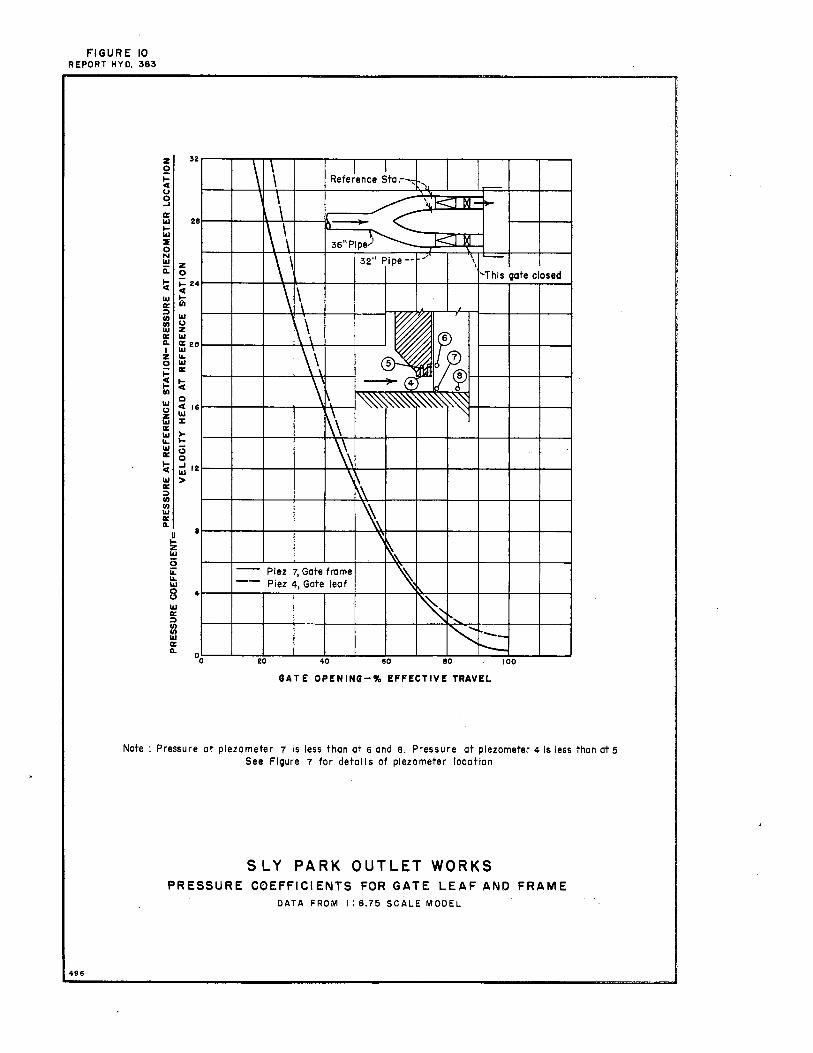
FIGURE 10 REPORT HYO. 383
z 2 ... 4 u 9 a: Ill ... Ill ::E 0 N Ill ii:
~ Ill a: ~ en 13 a: 0. I z
0 j:: :! en Ill 0
i5 a: Ill ... Ill a: ~ Ill a: ~ en en Ill a: 0.
u !z Ill i3 ii: ... Ill
8 Ill a:: ~ en 13 a: 0.
z 0
32
28
;: 24 4
t Ill u z Ill ffi 20 ... Ill a:
!i C 4 16 Ill %
> ... 0 0 ~ 12
>
a
4
\ \ I I I_ Reference Sta.-~ '),
1 \ ~
\i_rc-;_ I D(I-~
\ 11-\\ ), I< I IXI 36"Plpe.J
\' 32" Pipe-~ _, '\ -
I
'This gate closed
\ \ ,
.I ,
\\ i 7 \\ ~if j([, \, ~~
\\ ~\ ' \ \\ ~ \\
' \, -- Plez 7, Gate frame " -- Piez 4, Gate leaf " ~\
I',
I" .. __ r---
20 40 80 80 100
GATE OPENING-"- EFFECTIVE TRAVEL
Note : Pressure at plezometer 7 Is less than at 6 and 8. Pressure at plezometer 4 Is less than at 5 See Figure 7 for detal Is of plezometer location
498
SLY PARK OUTLET WORKS PRESSURE COEFFICIENTS FOR GATE LEAF AND FRAME
DATA FROM I: 6.75 SCALE MODEL
Sam Peng
Sticky Note
None set by Sam Peng
Sam Peng
Sticky Note
MigrationNone set by Sam Peng
Sam Peng
Sticky Note
Unmarked set by Sam Peng
Sam Peng
Sticky Note
None set by Sam Peng
Sam Peng
Sticky Note
MigrationNone set by Sam Peng
Sam Peng
Sticky Note
Unmarked set by Sam Peng