UNITARY PRODUCTS GROUP INSTALLATION … Install Guide.pdfWithout Basement Single Bedroom ... Insert...
22
INSTALLATION UNITARY PRODUCTS GROUP GUIDE Horizontal series HRV MODEL S1-HRV160 and MODEL S1-HRV220 ERV MODEL S1-ERV160 and MODEL S1-ERV220
Transcript of UNITARY PRODUCTS GROUP INSTALLATION … Install Guide.pdfWithout Basement Single Bedroom ... Insert...

INSTALLATION
UNITARY PRODUCTS GROUP
GUIDE
Horizontal seriesHRV MODEL S1-HRV160 and MODEL S1-HRV220ERV MODEL S1-ERV160 and MODEL S1-ERV220

2
About UsThe Unitary Products Group offers you a complete range of products designed to improve indoor air quality, and that provides a wide selection of accessories to facilitate installation.Our vision – To offer a complete range of HVAC products that satisfy environmentalconcerns.Whether your needs involve ventilation, purification, humidification or filtration, the Unitary Products Group has the customized solution for you, with its range of quality products backed by the best warranty in the industry.
Installation
1. Ventilation needs2. Types of installation3. HRV/ERV systems4. Finding a suitable installation area for the HRV or ERV5. Installation of the HRV/ERV6. Rigid duct7. Insulated flex from unit to outside wall8. Condensation drain line9. Devoted electric receptacle
10. Outside fresh air and exhaust air hoods11. Fresh air and exhaust air grilles12. Benefits of the Duotrol TM system13. Balancing the unit
Functions and Controls
14. Controls and wiring
Technical Information
15. Troubleshooting16. Wiring diagram17. Maintenance18. Specification and technical information
Peace of Mind All our products are backed
by the best limited warrantyin the industry.
You benefit from a lifetime warranty onthe core, a 10-year warranty (5 years + 5 years prorated) on our ventilationmotors, a 5-year warranty on theenthalpic core, and a 5-year warrantyon all other components.
33667789
1011121314
15
16171819
19. Limited Warranty 20
INFORMATION FOR INSTALLERS PAGE
EGAPSRELLATSNI DNA SRENWOEMOHROFNOITAMROFNI
EGAPSRELLATSNI DNA SRENWOEMOHROFNOITAMROFNI
INSTALLATIONGUIDE
3
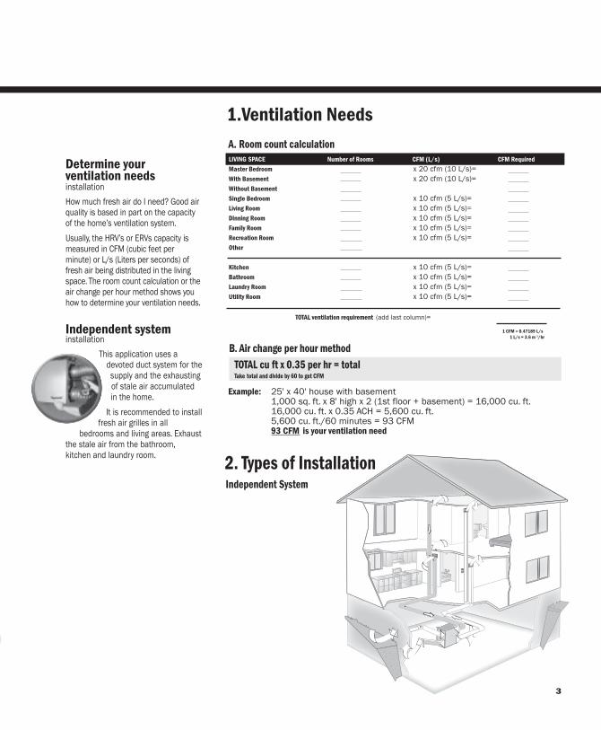
Determine yourventilation needsinstallationHow much fresh air do I need? Good airquality is based in part on the capacityof the home’s ventilation system.Usually, the HRV’s or ERVs capacity ismeasured in CFM (cubic feet perminute) or L/s (Liters per seconds) offresh air being distributed in the livingspace. The room count calculation or theair change per hour method shows youhow to determine your ventilation needs.
Independent systeminstallation
This application uses adevoted duct system for thesupply and the exhaustingof stale air accumulatedin the home.
It is recommended to installfresh air grilles in all
bedrooms and living areas. Exhaustthe stale air from the bathroom,kitchen and laundry room.
Independent System
A. Room count calculation
B. Air change per hour method
2. Types of Installation
1.Ventilation Needs
LIVING SPACEMaster BedroomWith BasementWithout BasementSingle BedroomLiving RoomDinning RoomFamily RoomRecreation RoomOther
KitchenBathroomLaundry RoomUtility Room
TOTAL cu ft x 0.35 per hr = totalTake total and divide by 60 to get CFM
Number of Rooms CFM (L/s) CFM Requiredx 20 cfm (10 L/s)= x 20 cfm (10 L/s)=
x 10 cfm (5 L/s)= x 10 cfm (5 L/s)= x 10 cfm (5 L/s)= x 10 cfm (5 L/s)= x 10 cfm (5 L/s)=
x 10 cfm (5 L/s)= x 10 cfm (5 L/s)= x 10 cfm (5 L/s)= x 10 cfm (5 L/s)=
TOTAL ventilation requirement (add last column)=
1 CFM = 0.47189 L/s1 L/s = 3.6 m 3/hr
Example: 25' x 40' house with basement1,000 sq. ft. x 8' high x 2 (1st floor + basement) = 16,000 cu. ft.16,000 cu. ft. x 0.35 ACH = 5,600 cu. ft.5,600 cu. ft./60 minutes = 93 CFM93 CFM is your ventilation need

4
4" to 12" maximum
Indirect Connection - Breathing Tee
Indirect Connection - Return Air Grille
2. Types of Installation (continued)
Exhaust at thesource and supplyin the returninstallation
This application uses adevoted duct system for the
exhausting of stale air accumulatedin the home. The fresh air is dumped intothe return air duct and is distributed thruthe home by the existing supply airductwork of the forced air system.
Make sure when using this application thatyour fresh air duct connection to the forcedair system return air duct is at least 3' fromthe forced air system. You should checkwith your local code or the forced airsystem’s manufacturer.
Forced Air System
6'
18"
*For minimum distance between return and forced airsystem, check with your local building codes and forcedair system manufacturer.
HRV/ERV
From Bathroom orKitchen
To living space
There are different practices used to combine HRV or ERV to a forced air system.
3'
Exhaust at the source
A Breathing Tee is a ventilation air supplyduct with an open tee located before theconnection to the return air duct. It allowsthe HRV to function without supply air flowrates being affected by the forced airsystem’s fan speed.
Leaving a gap in the ventilation air supplyduct in place of the breather tee isacceptable but not recommended.
With the return air grille approach, HRV orERV ventilation supply air is “dumped” neara grille (between 4" and 12") in the returnair duct upstream of the recirculation fan.
*See your local code before making an installation.
INSTALLATIONGUIDE

5
Exhaust andsupply in the returninstallation
When using thisapplication make surethat there is at least6' between the freshair and exhaust air
connections of theHRV or ERV in the return
air duct.Supply air from HRV or ERV must be atleast 3' from the forced air system. Canbe different from a region to an other.You should check with your local codeor the forced air system’smanufacturer.
Noteto installerFresh air must always be down-streamfrom the exhaust air in the return airduct of the forced air system.
Exhaust from the returnand supply in supplyinstallation
When using this application make surethat the Supply air from HRV or ERV isat least 3' from the forced air system.Can be different from a region to another. You should check with your localcode or the forced air system’smanufacturer.
2. Types of installation (continued)
Simplified Connection
Forced Air System
6’
18”
HRV / ERV
6’
3’Exhaust and supply in the return
Forced Air System
6’
18”
HRV / ERV
Exhaust from return and supply in supply
FOR MINIMUM DISTANCE BETWEENRETURN AND FORCED AIR SYSTEMCheck with your local building codes and force air system manufacturer.
To living space

Installation KitIncluded in the installation kit:
• 4 Collars• 2 Flexible Vinyl Ducts• 1 Condensation Drain Line• 1 Drain Adapter with Nut• 4 Tie Wraps (30”)•16 screws (#10 x 5/8") • 4 screws (#10 x 1")• 4 Washers
TIPSto installerRemoving the core unit will facilitate your job.
Figure 3.1 Pull out the inserts first then use the straps to lift the unit out of the box.
3. HRV/ERV systems
4. Finding a suitable installation area for HRV or ERV
Figure 3.2 Installation kit is shipped inside the unit. Figure 3.3 Installation kit.
The HRV or ERV units should be installed in a mechanical room or as close to an outsidewall as possible. This would assure a short run of insulated flexible duct.
The HRV or ERV unit must always be installed in an area where the air is tempered to avoidfreezing of the condensate line. The contractor should install the unit in area that is veryaccessible to allow the homeowner easy access for maintenance.
It is very important to install an electric receptacle (115v) near the HRV or ERV, a separatecircuit breaker is also recommended. You should have access to a condensate drain nearthe HRV or ERV to avoid the use of condensate pump.
INSTALLATIONGUIDE
6

The SPMTM system is suppliedwith the HRV or ERV to allowone person mounting of unit.
SPMTM
attachment system
Our entire line ofHRV/ERV productsare designed forinstallation by a single
person. “Single PersonMountingTM” will enable you
to save time and effort by offeringyou a variable attachment systemand maximizing your basementspace.
TIPSto installerIf unit is not level, improperdrainage will occur and could leadto moisture and leakage problems.
TIPSto installer
It is recommended to useapproximately 16" of flexible duct(supplied in kit) between the HRVor ERV and your rigid duct (seefigure 6.1). The flex duct ismounted the same way to the HRVor ERV as the insulated flex closeon step 6 (see figure 6.2).
figure 5.1 Place HRV/ERV on a stepladder.
figure 5.2 Attach your four straps to thefloor joist making sure that you attachthru the washers and the grommets.
figure 5.3 Pull on the middle strap andgently push upward on the unit. Thenrepeat procedure on other side.
figure 5.4 When completing theprocedure make sure that the HRV orERV is leveled.
5. Installation of the HRV/ERV
6. Rigid duct
figure 6.1 Mount flex to HRV/ERV. figure 6.2 Mount flex to rigid duct.
7

ISF TM
collar system(Patent Pending Technologies)
Quick and simple to installthanks to our revolutionary
“Insert Slide and FixTM”collar system.
The “ISFTM” collar system enables you tomanipulate duct within your reach andthen insert the collar to the HRV/ERVby sliding it in place, for a better andquicker installation.
TIPSto installer
To ensure a better installation and toavoid an undesired bend in the duct,align the duct with the collar beforesecuring over the four hooks.
The installer can now beneficiate from the ISFTM collar system for its flex duct installation tothe unit. Take four collars out of the unit. Insert the flex over the interior flange of the collar.Make sure that flex is pushed all the way, so the four tabs on the collar hooks on to the flex.Seal with tie wrap (4 tie wraps supplied with unit). Pull insulation over the interior flange.Pull vapor barrier over outer flange on the collar and seal with duct tape.
Once insulated flex is attached to the collar, slide collar in keeper section, fixed collar to theunit with four screws supplied in installation kit.
Insert the threaded drain adapter thru the bottom of the HRV or ERV and hand tighten theplastic nut supplied with the drain kit.
7. Insulated Flex from Unit to Outside Wall.
figure 7.1 ISF TM collar system - removable part.
figure 7.2 Insert vinyl duct over thehooks and seal with a 30" tie wrap.
figure 7.3 Insert insulation inside the collar.
figure 7.5 Slide collar on the unit. figure 7.6 Fix and secure with two screws supplied.
figure 7.4 Finish by taping the duct onthe collar.
INSTALLATIONGUIDE
8

9
Sloped Drain Pandrainage systemOur HRV/ERV units areequipped with an easy-
access sloped drain pan.Excess condensation that
might accumulate inside the unitmigrate to the centre of the drain panto be evacuated.
8. Condensation Drain Line
Insert the threaded drain adapter thru the bottom of the HRV or ERV and hand tighten theplastic nut supplied with the drain kit.Install the condensate line (10 feet included in drain kit). Insert condensate tubing by pushingclear plastic line over drain adapter. Make condensate trap by looping the clear plastic tubing.This procedure is to avoid foul odor to enter the HRV or ERV.
figure 8.1 Hand screw the drain adapter
figure 8.2 Insert condensate line. figure 8.3 Make a loop in condensate line. figure 8.4 Use a condensate pump ifyou don’t have access to the floor drain.

INSTALLATIONGUIDE
Insert the power cord on top of the unit.Press firmly to make sure the power cord issecure.
figure 9.1 HRV/ERV’s Power Cord
It is recommended that the HRV or ERV havea devoted receptacle with 115v. It is notrecommended to connect unit with anextension cord. If no receptacle is availableplease call an electrical contractor and haveone installed.
figure 9.2 Electric Wall Outlet
9. Devoted Electric Receptacle
10

10. Outside Fresh Air and Exhaust Air Hoods
figure 10.1 Locating outside hoods.
72"
18"
figure 10.4 Install outside hoods.
figure 10.2Insert vinyl duct over the hooks. Fix the collar on the floor joist.
figure 10.3Insert insulation inside the collar andfinish by taping the vapor barrier on the collar.
11
TIPSto installerTo make your installation easier use our double collar to install your flex pipe with the outside hoods (figure 10.2 and 10.3).
TIPSto installerWe manufacture a wide selection of:• Insulated flexpipe• Hoods
TIPSto installerExtend the sheet metal sleeve 1.5"inside the home. Attach specialtyISF TM collar to sheet metalsleeve.

INSTALLATIONGUIDE
12
11. Fresh Air and Exhaust Air Grilles
It is recommended to exhaust the stale air from the bathroom, kitchen, laundry room andstorage room. These areas have been found to be the most pollutant areas in a home.For the kitchen we recommend the use of grease filter grilles.
It is recommended to install fresh air grilles in all bedrooms and living areas. The exhaust airgrilles should be located in the bathrooms, kitchen, laundry room and storage room. Grilles areusually installed 12" from the ceiling.
Grilles are recommended for quiet air diffusion (4, 5, 6 and 8 inches are standard).
The grilles combined with a 4" space saving grille adapters (stack head elbow)makes for easy and time saving installation.
TIPSto installerNote: It is not recommended toexhaust your clothes dryer, your kitchenexhaust hood or your central vacuumcleaner thru your ventilation system.
Save Time and Space...Use a Stack Head Elbow Ask yourlocal distributor for more information
• Duct• Stack Head Elbow• Grilles
figure 11.1 Grille.
figure 11.2 Stack head elbow. figure 11.3 Insert grille.

13
Intermittent: When the selector switch is in the intermittent position the HRV or ERV will only runwhen there is a call for ventilation by any control. At that time the unit will run on high speed until the condition is satisfied.
Continuous:When the selector switch is in the continuous position the HRV or ERV will run continuously on low speed except when there is a call for override by any control.
Off:When the selector switch is in the off position the HRV or ERV will not come on even if there’s acall for ventilation by any control.
INTER.:Selects the exhaust air motor
CONT.:Selects both exhaust and fresh air motors
OFF:Selects the fresh air motor
+ Button: Increase the speed of the selected motor.
- Button: Decrease the speed of the selected motor.
DuoTrol TM
balancing system(Patent Pending Technologies)
Silent and economical... Byreducing motor speed to
balance the unit, you avoidthe noise that would beproduced by balancingdampers.
In addition, with thistechnology the unit will consume
less energy.
Modeselector
• Intermittent• Continuous
• Off
Balancingcontrol
• Intermittent• Continuous
• Off
• Increase Speed
• Decrease Speed
Acts as a mode selector
Acts as a balancing control (see instructions)
12. Benefits of the Duotrol TM System
figure 12.1 DuotrolTM System
The DuotrolTM lets contractor set speed of the motors for balancing purposes (Exhaust air, Fresh air and Both motors).
The Duotrol TM balancing system (patent pending) is state of the art technologysimplified for quick and easy installation for the contractor’s peace of mind. The Duotrol TM
serves two purposes.

INSTALLATIONGUIDE
TIPS to installerAs mentioned in the section, theDuotrolTM System has two differentpurposes.
1. Mode Selector2. Balancing Mode
The light indicator shows you in whichmode the DuotrolTM System is in.
GREEN LIGHTMode Selector
YELLOW LIGHTBalancing Mode
Using the Selector Switchto installer
When on Balancing Mode, the SelectorSwitch allows you to choose the motoryou want to set.
Closed Duotrol Cover
1. INTER (Exhaust Motor)2. CONT (Both Motors)3. OFF (Supply Motor)
or
Open Duotrol Cover
1. UP (Exhaust Motor)2. MIDDLE (Both Motors)3. DOWN (Supply Motor)
13. Balancing the unit
Step 1: Press the (+) and (–) buttons simultaneously until yousee the yellow light. Once the indicator light turns yellow youare in balancing mode.
Step 2: When in balancing mode the selector switch becomesthe motor selector switch. INTER (Right Motor), CONT (BothMotors) and OFF (Left Motor)
Step 3: Once the total cfm needed is determined, you canstart balancing the HRV/ERV. Set your fresh air supply byselecting the “OFF” position on the DuotrolTM. Install yourmagnehelic gauge and air flow grid in the fresh air duct.
Step 4: Press the (–) button to decrease the cfm or press the(+) button to increase the CFM.
Step 5: Then perform the same operation on the stale air sideby selecting the “INTER” position on the DuotrolTM.
Step 6: The “CONT” position will allow you to adjust the cfmon both motors proportionately (if necessary).
Step 7: Once this is completed, you have set the high speedon your HRV/ERV. To lock balancing mode you must press (+)and (–) buttons simultaneously and release. The indicator lightwill turn green to indicate normal operation mode.
Step 8: Once high speed is set and locked, switch tocontinuous on the DuotrolTM. By using (+) and (-) buttons setlow speed on the HRV/ERV.
Step 9: Select the mode of operation.(Intermittent, Recirculation or Continuous Ventilation)
figure 13.1 DuotrolTM System
figure 13.2 Magnehelic Gauge with Air Flow Grid
figure 15.6 Selector Switch
figure 13.3 Magnehelic Gauge with Air Flow Grid
figure 13.4 Inserting Air flow grid in duct
figure 13.5 Seal Air flow grid in duct with duct tape.14

14. Controls and Wiring
The S1-DEHUSTAT allows the homeowner control of the indoor humidity level.
The S1-DEHUSTAT dehumidistat is a two wire connection. On the Duotrol System and the S1-DEHUSTAT use R and G terminal connections on the lower right hand side of the
TM
control board.
S1-DEHUSTAT modelDEHUMIDISTAT
Features• Dehumidistat to select the humidity level
figure 14.1 S1-DEHUSTAT figure 14.2 DuotrolTM
Range of controlsOur entire range of controls
is offered with featuresmaking your ventilation
system simple, easy tooperate and backed bya 5-year limited warranty.
15

16
PROBLEMS
• HRV or ERV not running
• Air is too dry
• Air too humid
SOLUTIONS
• Verify breaker in electrical box
• Verify that dehumidistat or switch on HRV or ERV are activated to supply power to unit.
• Unplug HRV or ERV verify if controller is wired correctly to the connection box on the side of the unit.
• Verify low voltage box (DuotrolTM)on the unit
•Increase humidity level on dehumidistat.
•Switch ventilation mode from continuous to intermittent
•Install a Unitary Products Group humidifier
•Reduce the humidity level on the controller.
• Verify if dryer is venting in basement.
• Verify if heating wood is stored in basement.
• Wait for outside temperature to change.Ex. Summer can be extremely humid.
• Verify balancing of the HRV or ERV.
Peace of MindEnsure your comfort in theyears to come by usingUnitary Products Group
systems and accessories to install any ventilation,
humidification, purificationor filtration product.
Need help? You benefit from certifiedcustomer service ready to guide you in the installation or operation of yourUnitary Products Group system.Call: 1-800-536-6112
15. Troubleshooting

17
INSTALLATIONGUIDE
Standard Forced AirInterlocking Wiring
A relay is normally used when tying aventilation system onto forced airdistribution system. Our Duotrol Systemis equipped with an internal relay thatwill activate the forced air system’ventilator when there is a demand fromthe HRV/ERV. The Duotrol System willactivate the INTERLOCK relay during thefollowing modes: Continuous, Override,Recirculation and Defrost. See wiringdiagram.
Alternate Forced AirInterlocking WiringSome forced air system thermostat willactivate the cooling system when tiedusing the “Standard forced air interlocking wiring”.If you have identify this type ofthermostat you must proceed with the“Alternate forced air wiring”.
Locating the Wiring Diagramto installer
Wiring diagram for the entire line ofprofessional and furnace models are placed on the back of eachexhaust motor bracket.
16. Wiring Diagram
Standard Forced Air Interlock Wiring
Alternate Forced Air Interlock Wiring
*Before tying the HRV/ERV to aforced air system,always refer tosystem’s manual or manufacturer.

18
When should I Service myHRV/ERV?service and accessories
HEAT RECOVERY CORE UNITOnce a year or as needed,vacuum the four surfaces,let soak in warm water forthree hours, then spray
rinse and let dry.
FILTERSFour times a year or as needed, vacuumthe filters. Replace filters once a year.
INSIDE THE UNITOnce a year or as needed, clean theinterior of the unit (walls and drain pan)with a mild and non abrasive soap. It isrecommended to use products that areenvironmentally-friendly.
ENERGY RECOVERY CORE UNITOnce a year or as needed, vacuum the four surfaces.
Noteto installerIMPORTANT : ALWAYS UNPLUG HRV ORERV DURING SERVICING
17. Maintenance
figure 17.1 Slide Out the Filters figure 17.2 Vacuum the Filters
figure 17.3 Slide out the Energy Core figure 17.4 Wash the Walls of the Unit
19
PROFESSIONAL,DELUXE AND FURNACE MODELS
INSTALLATIONGUIDE
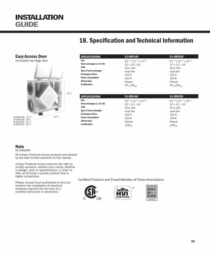
Easy Access Doorremovable top hinge door
Noteto installerAll Unitary Products Group products are backedby the best limited warranty on the market.
Unitary Products Group reserves the right to modify aproduct, without prior notice, whether in design, color or specifications, in order tooffer at all times a quality product that ishighly competitive.
Please consult local authorities to find outwhether the installation of electricalproducts requires the services of acertified technician or electrician.
237/8"
211/2"
18. Specification and Technical Information
Certified Products and Proud Member of These Associations
SPECIFICATIONSSizeHeat exchanger (L x H x W)CFMType of heat exchangerExchange surfacePower consumptionDefrost typeCertification
S1-HRV220S1-HRV160237/8" x 211/2" x 113/8" 7/8" x 211/2" x 161/2"
"51 x "21 x "21"01 x "21 x "21022 ot 05061 ot 03
wolf-ssorcwolf-ssorc104 ft2 150 ft2
W 051W 031tsuahxEtsuahxE
HVI, CCSAUS HVI, CCSAUS
SPECIFICATIONSSizeHeat exchanger (L x H x W)CFMType of heat exchangerExchange surfacePower consumptionDefrost typeCertification
S1-ERV220S1-ERV16023
23
237/8" x 211/2" x 113/8" 7/8" x 211/2" x 161/2""51 x "21 x "21"01 x "21 x "21
022 ot 05061 ot 03wolf-ssorcwolf-ssorc
104 ft2 150 ft2
W 051W 031tsuahxEtsuahxE
CCSA CSU CSAUS
SI-HRV160 113/8"SI-HRV220 161/2"SI-ERV160 113/8"SI-ERV220 161/2"
*

INSTALLATIONGUIDE
20
ERVs & HRVs, if properly registered by the return of the attached warranty registration to Unitary Products Group, are warranted to the consumer against defects in materials and workmanship for a period of ten years from the date of installation, on the HRV core. Five years on the ERV core.Five years plus five years prorated on the ventilation motors. Five years on all other components so long as the product has been installed and operated in accordance with all appropriate manuals and wiring diagrams. Any other defective parts will be repaired without charge except for removal, reinstallation and transportation costs. To obtain repair service under this limited warranty, the consumer must send the defective partto Unitary Products Group.
THERE ARE NOT EXPRESS WARRANTIES COVERING THIS HUMIDIFIER OTHER THAN AS SET FORTH ABOVE. THE IMPLIED WARRANTIESOF MERCHANTABILITY AND FITNESS FOR A PARTICULAR PURPOSE ARE EXPRESSLY EXCLUDED. THE MANUFACTURER ASSUMESNO LIABILITY IN CONNECTION WITH THE INSTALLATION OR USE OF THIS PRODUCT, EXCEPT AS STATED IN THE LIMITED WARRANTY. THE MANUFACTURER WILL IN NO EVENT BE LIABLE FOR INCIDENTAL OR CONSEQUENTIAL DAMAGES.
This limited warranty gives you specific legal rights, and you may also have other rights which vary from state to state. Some states do not allow either limitations on implied warranties, or exclusions from incidental or consequential damages, so the above exclusion and limitation may not apply to you.
Any questions pertaining to this limited warranty should be addressed to Unitary Products Group. The Unitary Products Group has elected not to make available the informal dispute settlement mechanism which is specified in the Magnuson-Moss Warranty Act.
Unitary Products Group 5005 York Drive Norman OK, 73069 www.source1parts.com
Tel. 1-800-536-6112 OWNER'S NAMENom du propriétaire:
MODEL S1-HRV160MODÈLE S1-HRV160
WARRANTY REGISTRATIONEnregistrement de la garantie
LIMITED WARRANTY
STREET ADDRESSAdresse:
DEALER'S NAMENom du marchand:
DATE OF INSTALLATIONDATE DE INSTALLATION
CITYVille:
POSTAL CODECode postal:
STATEProvince:
STREET ADDRESSAdresse:CITYVille:
POSTAL CODECode postal:
STATEProvince:
SERIAL NUMBERNUMÉRO DE SÉRIE
S1-HRV220S1-HRV220
S1-ERV160S1-ERV160
S1-ERV220S1-ERV220

21
NOTES _____________________________________________________________________________________________________________________________________________________________________________________________
_______________________________________________________________________________________________________________________
_______________________________________________________________________________________________________________________
_______________________________________________________________________________________________________________________
_______________________________________________________________________________________________________________________
_______________________________________________________________________________________________________________________
_______________________________________________________________________________________________________________________
_______________________________________________________________________________________________________________________
_______________________________________________________________________________________________________________________
_______________________________________________________________________________________________________________________
_______________________________________________________________________________________________________________________
_______________________________________________________________________________________________________________________
_______________________________________________________________________________________________________________________
_______________________________________________________________________________________________________________________
_______________________________________________________________________________________________________________________
_______________________________________________________________________________________________________________________
_______________________________________________________________________________________________________________________
_______________________________________________________________________________________________________________________
_______________________________________________________________________________________________________________________
_______________________________________________________________________________________________________________________
_______________________________________________________________________________________________________________________
_______________________________________________________________________________________________________________________
_______________________________________________________________________________________________________________________
_______________________________________________________________________________________________________________________
_______________________________________________________________________________________________________________________

5005 York Drive Norman Ok, 73069 Tel. 1-800-536-6112http://www.source1parts.com
Agency:
Form
160
04
UNITARY PRODUCTS GROUP