Testing & Software Quality Seminar on software quality 13.5.2005 Karipekka Kaunisto.
Upload
hector-walkerCategory
view
218download
0
1
UNIT VIAdvanced software Engineering
2
Software QualityDefinition:
Software Quality is conformance to
1. Explicitly stated functional and performance requirements
2. Explicitly documented development standards
3. Implicit characteristics that are expected of all professionally developed software
Definition emphasizes three important Points:1.Requirement
2. Specified Standard
3. Implicit Requirement
3
Continued.. Explicit software requirements are the foundation from which
quality is measured. Lack of conformance to requirements is lack of quality
Specific standards define a set of development criteria that guide the manner in which software is engineered. If the criteria are not followed, lack of quality will most surely result
There is a set of implicit requirements that often goes unmentioned (e.g., ease of use). If software conforms to its explicit requirements but fails to meet implicit requirements, software quality is suspect
4
McCall’s Quality Factors
The Factor that affect the software Quality can categorized in two broad category
1. Some factors can be directly measured (e.g. defects uncovered during testing)
2. Other factors can be measured only indirectly (e.g., usability or maintainability)
Software quality factors can focus on three important aspects
1. Product operation: Its operational characteristics
2. Product revision: Its ability to undergo change
3. Product transition: Its adaptability to new environments
5
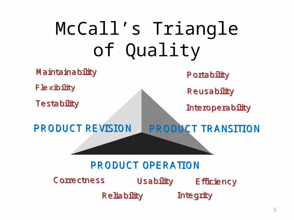
McCall’s Triangle of Quality
Ma in ta in a b ilityMa in ta in a b ility
F le x ib ilityF le x ib ility
T e s ta b ilityT e s ta b ility
P o rta b ilityP o rta b ility
R e u s a b ilityR e u s a b ility
In te ro p e ra b ilityIn te ro p e ra b ility
C o rre c tn e s sC o rre c tn e s s
R e lia b ilityR e lia b ility
E ffic ie n c yE ffic ie n c y
In te g rityIn te g rity
U s a b ilityU s a b ility
P R O DU C T TR A NS ITIONP R O DU C T TR A NS ITIONP R O DU C T R E VIS IONP R O DU C T R E VIS ION
P R O DU C T OP E R A TIONP R O DU C T OP E R A TION
6
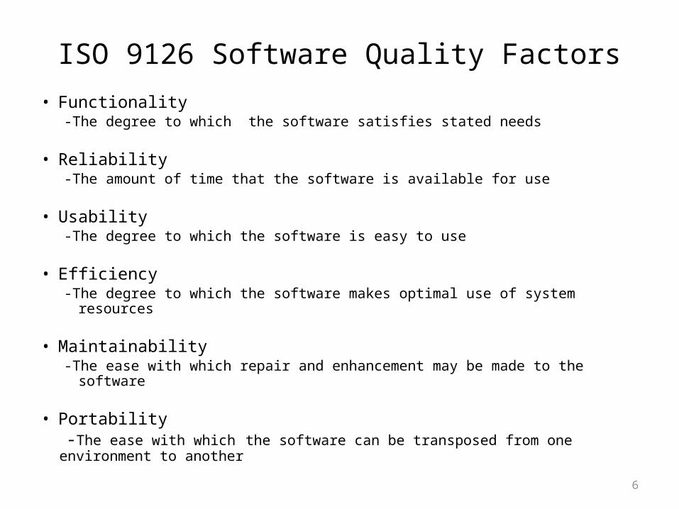
ISO 9126 Software Quality Factors• Functionality
-The degree to which the software satisfies stated needs
• Reliability-The amount of time that the software is available for use
• Usability-The degree to which the software is easy to use
• Efficiency-The degree to which the software makes optimal use of system resources
• Maintainability-The ease with which repair and enhancement may be made to the software
• Portability -The ease with which the software can be transposed from one environment to another
7
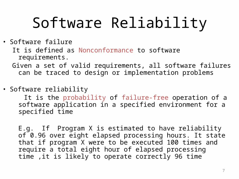
Software Reliability• Software failure
It is defined as Nonconformance to software requirements.Given a set of valid requirements, all software failures can be
traced to design or implementation problems
• Software reliability It is the probability of failure-free operation of a software
application in a specified environment for a specified time
E.g. If Program X is estimated to have reliability of 0.96 over eight elapsed processing hours. It state that if program X were to be executed 100 times and require a total eight hour of elapsed processing time ,it is likely to operate correctly 96 time
8
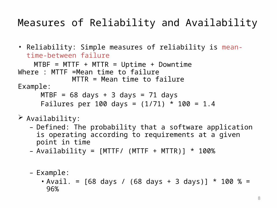
Measures of Reliability and Availability
• Reliability: Simple measures of reliability is mean-time-between failure
MTBF = MTTF + MTTR = Uptime + DowntimeWhere : MTTF =Mean time to failure MTTR = Mean time to failureExample:
MTBF = 68 days + 3 days = 71 daysFailures per 100 days = (1/71) * 100 = 1.4
Availability:– Defined: The probability that a software application is operating
according to requirements at a given point in time– Availability = [MTTF/ (MTTF + MTTR)] * 100%
– Example: • Avail. = [68 days / (68 days + 3 days)] * 100 % = 96%
9
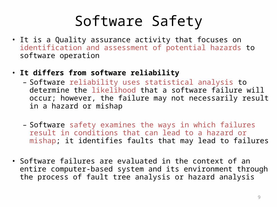
Software Safety• It is a Quality assurance activity that focuses on identification and
assessment of potential hazards to software operation
• It differs from software reliability – Software reliability uses statistical analysis to determine the
likelihood that a software failure will occur; however, the failure may not necessarily result in a hazard or mishap
– Software safety examines the ways in which failures result in conditions that can lead to a hazard or mishap; it identifies faults that may lead to failures
• Software failures are evaluated in the context of an entire computer-based system and its environment through the process of fault tree analysis or hazard analysis
10
Formal Method Concept
Problems with Conventional Specification• contradictions• ambiguities• vagueness• incompleteness• mixed levels of abstraction
11
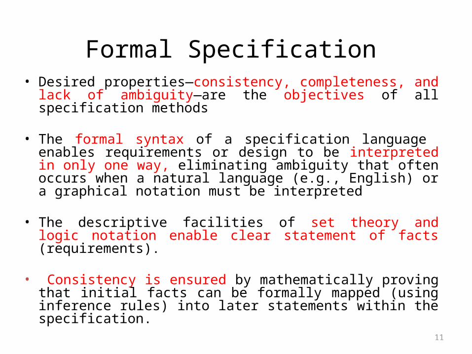
Formal Specification• Desired properties—consistency, completeness, and lack of
ambiguity—are the objectives of all specification methods
• The formal syntax of a specification language enables requirements or design to be interpreted in only one way, eliminating ambiguity that often occurs when a natural language (e.g., English) or a graphical notation must be interpreted
• The descriptive facilities of set theory and logic notation enable clear statement of facts (requirements).
• Consistency is ensured by mathematically proving that initial facts can be formally mapped (using inference rules) into later statements within the specification.

12
Formal Methods Concepts• Data invariant—a condition that is true throughout the execution of
the system that contains a collection of data
• State– Many formal languages, such as OCL, use the notion of states as
they were discussed earlier, that is, a system can be in one of several states, each representing an externally observable mode of behavior.
– The Z language defines a state as the stored data which a system accesses and alters
• Operation—an action that takes place in a system and reads or writes data to a state– precondition defines the circumstances in which a particular
operation is valid– postcondition defines what happens when an operation has
completed its action
13
Example of Block handler
What is block handler?– One important part of operating system is subsystem that
maintains file created by user.– Part of filling subsystem is block handler– Files in file store are composed of blocks– Block handler will maintain the reservoir of unused or free
block and keep track of block that are currently in use.– Block released from a deleted file they are normally added to
queue of blocks waiting to be added to the reservoir of unused block
– Each Element of the queue containing set of blocks from deleted file

14
Block handler
15
Continued……States:• State is collection of free blocks, collection of used blocks, and queue
of the returned blocks.
Data Invariant:• No block will be marked as both unused and used.
• All the sets of blocks held in the queue will be subsets of the collection of currently used blocks.
• No elements of the queue will contain the same block numbers.
• The collection of used blocks and blocks that are unused will be the total collection of blocks that make up files.
• The collection of unused blocks will have no duplicate block numbers.
• The collection of used blocks will have no duplicate block numbers.

16
Continued……
Operations• add(): An operation which adds a collection of blocks to the
end of the queue
• remove(): An operation which removes a collection of used blocks from the front of the queue and place them in the collection of unused blocks
• check(): An operation which checks whether the queue of blocks is empty

17
Continued……Pre- & Postconditions For the first operation:
Precondition: the blocks to be added must be in the collection of used blocks.
Postcondition: the collection of blocks is now found at the end of the queue.
For the second operation:
Precondition: the queue must have at least one item in it.
Postcondition: the blocks must be added to the collection of unused blocks.
For the third one:
Precondition: no
Postcondition: delivers the value of true if the queue is empty and false otherwise.
18
Mathematical Concepts
• sets and constructive set specification• set operators• logic operators• sequences

19
Sets and Constructive Specification
• A set is a collection of objects or elements and is used as a cornerstone of formal methods.– Enumeration
• {C++, Pascal, Ada, COBOL, Java}• #{C++, Pascal, Ada, COBOL, Java} implies cardinality = 5
– Constructive set specification is preferable to enumeration because it enables a succinct definition of large sets.
• {x, y : N | x + y = 10●(x, y2)}
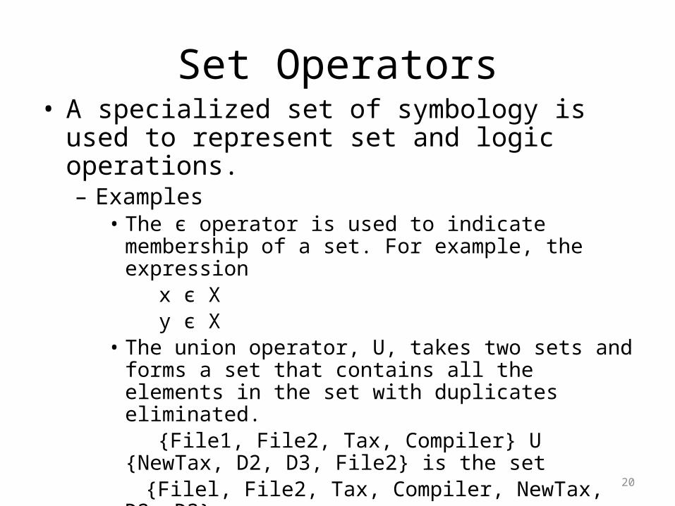
Set Operators• A specialized set of symbology is used to represent
set and logic operations. – Examples
• The є operator is used to indicate membership of a set. For example, the expression
x є Xy є X
• The union operator, U, takes two sets and forms a set that contains all the elements in the set with duplicates eliminated.
{File1, File2, Tax, Compiler} U {NewTax, D2, D3, File2} is the set
{Filel, File2, Tax, Compiler, NewTax, D2, D3}
• Other Operators are , ×, P,
20
21
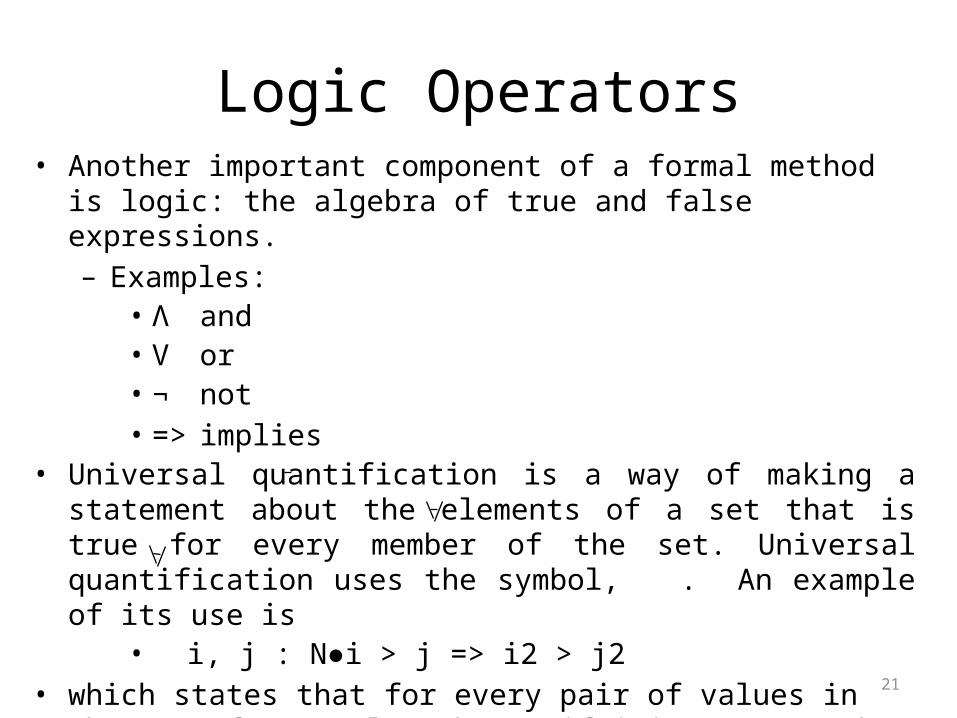
Logic Operators• Another important component of a formal method is logic: the algebra
of true and false expressions. – Examples:
• Λ and• V or• ¬ not• => implies
• Universal quantification is a way of making a statement about the elements of a set that is true for every member of the set. Universal quantification uses the symbol, . An example of its use is
• i, j : N●i > j => i2 > j2• which states that for every pair of values in the set of natural numbers,
if i is greater than j, then i2 is greater than j2.
22
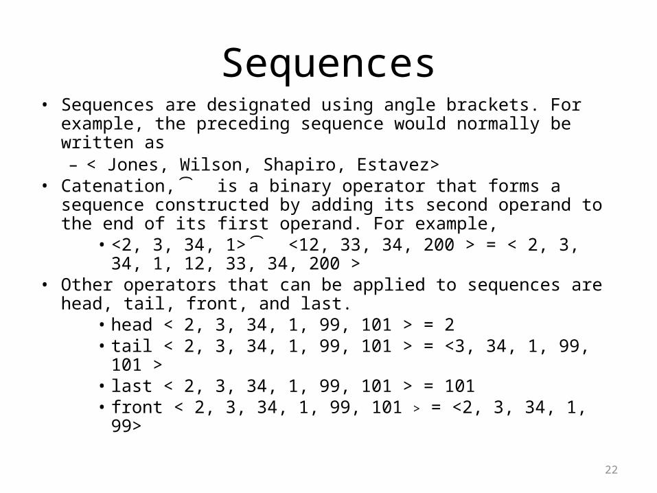
Sequences• Sequences are designated using angle brackets. For example, the
preceding sequence would normally be written as– < Jones, Wilson, Shapiro, Estavez>
• Catenation, Y is a binary operator that forms a sequence constructed by adding its second operand to the end of its first operand. For example,
• <2, 3, 34, 1> Y <12, 33, 34, 200 > = < 2, 3, 34, 1, 12, 33, 34, 200 >
• Other operators that can be applied to sequences are head, tail, front, and last.
• head < 2, 3, 34, 1, 99, 101 > = 2• tail < 2, 3, 34, 1, 99, 101 > = <3, 34, 1, 99, 101 >• last < 2, 3, 34, 1, 99, 101 > = 101 • front < 2, 3, 34, 1, 99, 101 > = <2, 3, 34, 1, 99>

23
Formal Specification Languages• A formal specification language is usually composed of three
primary components: – a syntax that defines the specific notation with which the
specification is represented– semantics to help define a "universe of objects“ that will
be used to describe the system– a set of relations that define the rules that indicate which
objects properly satisfy the specification• The syntactic domain of a formal specification language is
often based on a syntax that is derived from standard set theory notation and predicate calculus.
• The semantic domain of a specification language indicates how the language represents system requirements.
24
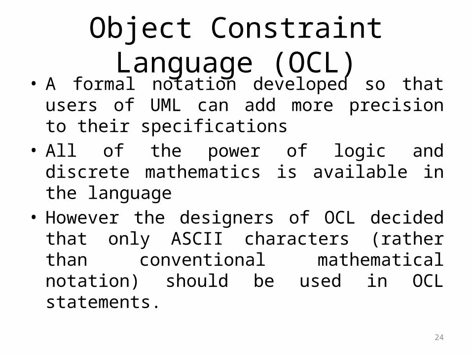
Object Constraint Language (OCL)• A formal notation developed so that users of UML
can add more precision to their specifications• All of the power of logic and discrete mathematics is
available in the language• However the designers of OCL decided that only
ASCII characters (rather than conventional mathematical notation) should be used in OCL statements.
25
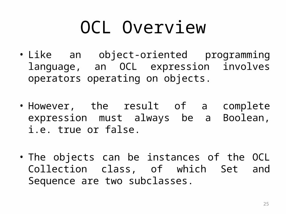
OCL Overview
• Like an object-oriented programming language, an OCL expression involves operators operating on objects.
• However, the result of a complete expression must always be a Boolean, i.e. true or false.
• The objects can be instances of the OCL Collection class, of which Set and Sequence are two subclasses.
26
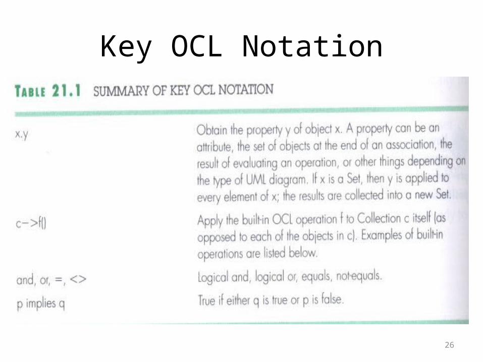
Key OCL Notation
27
Key OCL Notation
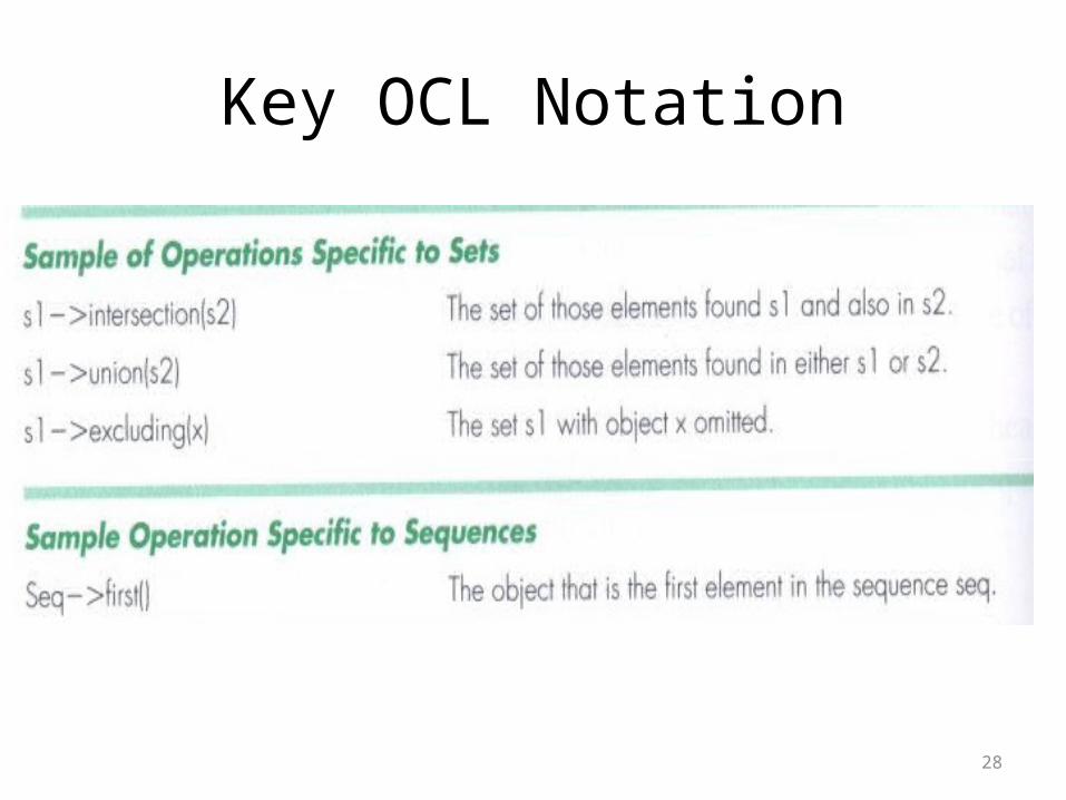
28
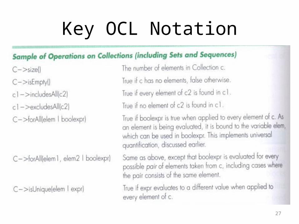
Key OCL Notation

29
BlockHandler using UML
Block
number
addBlock()
BlockHandler
BlockSet
1
*
1*
removeBlock()
allBlocks
free used
blockQueue
{ordered}
{subset}
{subset}
**
*
1 1 1
elements

30
BlockHandler in OCL
• No block will be marked as both unused and used. context BlockHandler inv: (self.used->intersection(self.free)) ->isEmpty()
• All the sets of blocks held in the queue will be subsets of the collection of currently used blocks.
context BlockHandler inv: blockQueue->forAll(aBlockSet | used->
includesAll(aBlockSet ))
31
BlockHandler in OCL
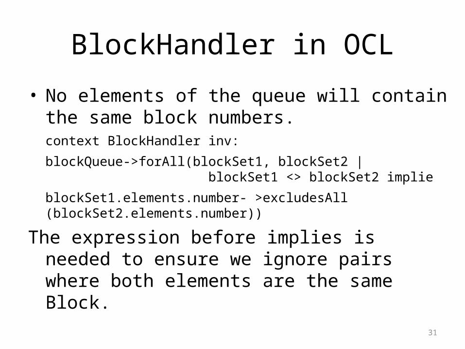
• No elements of the queue will contain the same block numbers.context BlockHandler inv:
blockQueue->forAll(blockSet1, blockSet2 | blockSet1 <> blockSet2 implie
blockSet1.elements.number- >excludesAll (blockSet2.elements.number))
The expression before implies is needed to ensure we ignore pairs where both elements are the same Block.
32
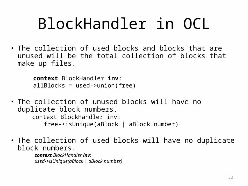
BlockHandler in OCL• The collection of used blocks and blocks that are unused will be the
total collection of blocks that make up files.
context BlockHandler inv: allBlocks = used->union(free)
• The collection of unused blocks will have no duplicate block numbers.
context BlockHandler inv: free->isUnique(aBlock | aBlock.number)
• The collection of used blocks will have no duplicate block numbers. context BlockHandler inv: used->isUnique(aBlock | aBlock.number)

33
BlockHandler in OCLPreconditions and postconditions for operations:
context BlockHandler::removeBlock() pre: blockQueue->size()>0 post: used = used@pre-block@pre->first() and free = free@pre->union(blockQueue@pre->first()) and blockQueue = blockQueue@pre-> excluding(blockQueue@pre->first)
context BlockHandler::addBlock() pre: used->includesAll(aBlockSet.elements) post: blockQueue.elements = blockQueueSet.elements@pre ->append(aBlockSet)) and used = used@pre and free = free@pre
34
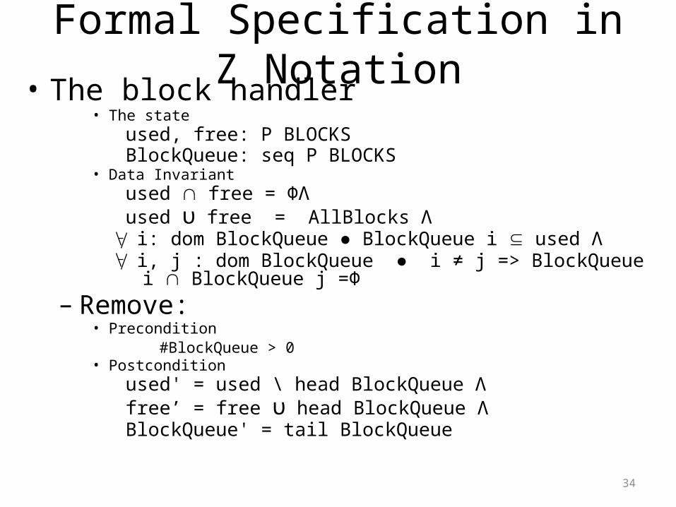
Formal Specification in Z Notation• The block handler
• The stateused, free: P BLOCKSBlockQueue: seq P BLOCKS
• Data Invariantused free = ΦΛused υ free = AllBlocks Λ i: dom BlockQueue ● BlockQueue i used Λ i, j : dom BlockQueue ● i ≠ j => BlockQueue i BlockQueue j =Φ
– Remove:• Precondition
#BlockQueue > 0• Postcondition
used' = used \ head BlockQueue Λ free’ = free υ head BlockQueue ΛBlockQueue' = tail BlockQueue
35
Software ReuseDefinition: Reused based software engineering is an approach to development that tries to maximize the reuse of existing software.
Depending upon the size of software unit reused there are three types.
1. Application system reuse: The whole of an application system may be reused either by incorporating it without change into other systems or by developing application families2. Component reuse: Components of an application from sub-systems to single objects may be reused3.Object & Function reuse: Software components that implement a single well-defined function may be reused
36
Benefits of reuse
1. Increased dependability
– Components exercised in working systems
2.Reduced process risk– Less uncertainty in development costs
3.Effective use of specialists– Reuse components instead of people
4.Standards compliance– Embed standards in reusable components
5.Accelerated development– Avoid original development and hence speed-up production
37
Reuse problems
• Increased maintenance costs• Lack of tool support• Not-invented-here syndrome• Maintaining a component library• Finding and adapting reusable components
38
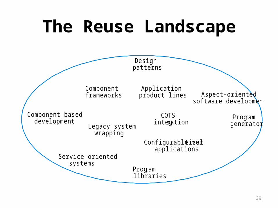
The Reuse Landscape
• Although reuse is often simply thought of as the reuse of system components, there are many different approaches to reuse that may be used.
• Reuse is possible at a range of levels from simple functions to complete application systems.
• The reuse landscape covers the range of possible reuse techniques.
39
The Reuse Landscape
Designpatterns
Component-baseddevelopment
Componentframeworks
Service-orientedsystems
COTSintegration
Applicationproduct lines
Legacy systemwrapping
Programlibraries
Programgenerators
Aspect-orientedsoftware development
Configurable verticalapplications

40
Reuse ApproachApproach Description
Design patterns Generic abstractions that occur across applications are represented as design patterns that show abstract and concrete objects and interactions.
Component-based development
Systems are developed by integrating components (collections of objects) that conform to component-model standards.
Application frameworks Collections of abstract and concrete classes that can be adapted and extended to create application systems.
Legacy system wrapping
Legacy systems that can be ‘wrapped’ by defining a set of interfaces and providing access to these legacy systems through these interfaces.
Service-oriented systems
Systems are developed by linking shared services that may be externally provided.
Application product lines
An application type is generalised around a common architecture so that it can be adapted in different ways for different customers.
COTS integration Systems are developed by integrating existing application systems.
Configurable vertical applications
A generic system is designed so that it can be configured to the needs of specific system customers.

41
Reuse Approach
Approach DescriptionProgram libraries Class and function libraries implementing commonly-
used abstractions are available for reuse.
Program generators A generator system embeds knowledge of a particular types of application and can generate systems or system fragments in that domain.
Aspect-oriented software development Shared components are woven into an application at different places when the program is compiled.

42
Reuse planning factors
• The development schedule for the software.• The expected software lifetime.• The background, skills and experience of the development
team.• The criticality of the software and its non-functional
requirements.• The application domain.
• The execution platform for the software.

43
Approaches to Software Reuse1. Application Framework
2. Software Product Line
1. Application Framework• Frameworks are a sub-system design made up of a collection
of abstract and concrete classes and the interfaces between them.
• The sub-system is implemented by adding components to fill in parts of the design and by instantiating the abstract classes in the framework.
• Frameworks are moderately large entities that can be reused.
44
Continued....
Framework classes:
1. System infrastructure frameworks
Support the development of system infrastructures such as communications, user interfaces and compilers.
2. Middleware integration frameworks
Standards and classes that support component communication a
nd information exchange.
3. Enterprise application frameworks
Support the development of specific types of application such as telecommunications or financial systems.
45
Continued…..
2. Software product lines Software product lines or application families are
applications with generic functionality that can be adapted and configured for use in a specific context.
Adaptation may involve:– Component and system configuration;– Adding new components to the system;– Selecting from a library of existing components;– Modifying components to meet new requirements
46
Continued…..
Product line specialisation:
• Platform specialisation– Different versions of the application are developed for different
platforms.• Environment specialisation
– Different versions of the application are created to handle different operating environments e.g. different types of communication equipment.
• Functional specialisation– Different versions of the application are created for customers with
different requirements.• Process specialisation
– Different versions of the application are created to support different business processes
47
Distributed Software EngineeringDistributed systems:Distributed System is a collection of independent computers that
appears to the user as a single coherent system.Distributed system characteristics:1.Resource sharing: Sharing of hardware and software resources.2. Openness: Use of equipment and software from different vendors.3. Concurrency: Concurrent processing to enhance performance.4. Scalability: Increased throughput by adding new resources.5. Fault tolerance: The ability to continue in operation after a fault has
occurred.Distributed systems issues:1.More Complex2.Independent Management3.No Single authority

48
Design issues1. Transparency: To what extent should the distributed system
appear to the user as a single system?
2. Openness: Should a system be designed using standard protocols that support interoperability?
3. Scalability : How can the system be constructed so that it is scaleable?
4. Security : How can usable security policies be defined and implemented?
5. Quality of service : How should the quality of servicebe specified.
6. Failure management : How can system failures be detected, contained and repaired?
49
Types of attackThe types of attack that a distributed system must defend itself against are:– Interception: where communications between parts of the
system are intercepted by an attacker so that there is a loss of confidentiality.
– Interruption: where system services are attacked and cannot be delivered as expected.
Denial of service attacks involve bombarding a node with illegitimate service requests so that it cannot deal with valid requests.
– Modification: where data or services in the system are changed by an attacker.
– Fabrication: where an attacker generates information that should not exist and then uses this to gain some privileges.
50
Models of interaction
Two types of interaction between components in a distributed system– Procedural interaction, where one computer calls
on a known service offered by another computer and waits for a response.
– Message-based interaction, involves the sending computer sending information about what is required to another computer. There is no necessity to wait for a response.
51
Remote procedure calls
Procedural communication in a distributed system is implemented using remote procedure calls (RPC).
In a remote procedure call, one component calls another component as if it was a local procedure or method. The middleware in the system intercepts this call and passes it to a remote component.
This carries out the required computation and, via the middleware, returns the result to the calling component.
A problem with RPCs is that the caller and the callee need to be available at the time of the communication, and they must know how to refer to each other.

52
Message passing Message-based interaction normally involves one component
creating a message that details the services required from another component
Through the system middleware, this is sent to the receiving component
The receiver parses the message, carries out the computations and creates a message for the sending component with the required results.
In a message-based approach, it is not necessary for the sender and receiver of the message to be aware of each other. They simple communicate with the middleware.

53
Middleware The components in a distributed system may be implemented in
different programming languages and may execute on completely different types of processor. Models of data, information representation and protocols for communication may all be different.
Middleware is software that can manage these diverse parts, and ensure that they can communicate and exchange data.

54
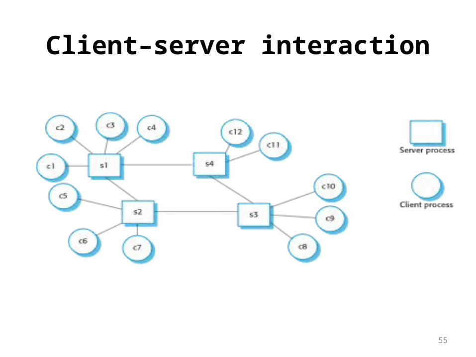
Client-server computing
• Distributed systems that are accessed over the Internet are normally organized as client-server systems.
• In a client-server system, the user interacts with a program running on their local computer (e.g. a web browser or phone-based application). This interacts with another program running on a remote computer (e.g. a web server).
• The remote computer provides services, such as access to web pages, which are available to external clients.
55
Client–server interaction
56
Architectural patterns
Widely used ways of organizing the architecture of a distributed system:– Master-slave architecture, which is used in real-time systems in
which guaranteed interaction response times are required.– Two-tier client-server architecture, which is used for simple client-
server systems, and where the system is centralized for security reasons.
– Multi-tier client-server architecture, which is used when there is a high volume of transactions to be processed by the server.
– Distributed component architecture, which is used when resources from different systems and databases need to be combined, or as an implementation model for multi-tier client-server systems.
– Peer-to-peer architecture, which is used when clients exchange locally stored information and the role of the server is to introduce clients to each other
57
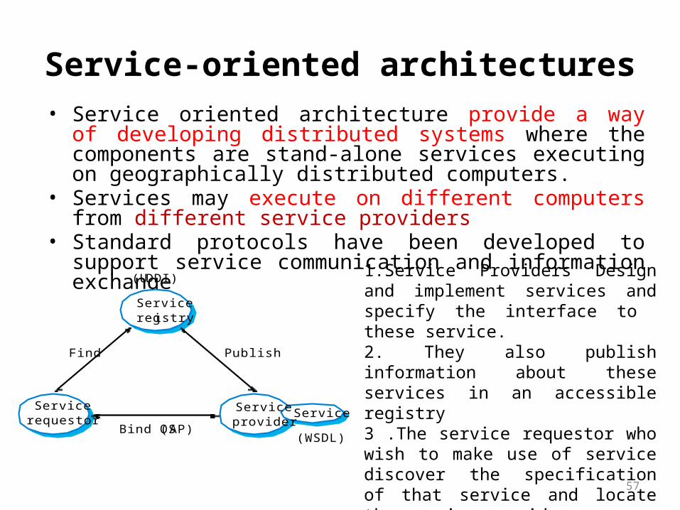
Service-oriented architectures• Service oriented architecture provide a way of developing
distributed systems where the components are stand-alone services executing on geographically distributed computers.
• Services may execute on different computers from different service providers
• Standard protocols have been developed to support service communication and information exchange
Serviceregistry
Servicerequestor
Serviceprovider
Service
Find Publish
Bind (SOAP)(WSDL)
(UDDI) 1.Service Providers Design and implement services and specify the interface to these service.2. They also publish information about these services in an accessible registry 3 .The service requestor who wish to make use of service discover the specification of that service and locate the service provider4. The can then bind their application to that specific service and communicate with it using standard service protocols

58
Benefits of SOA
• Services can be provided locally or outsourced to external providers
• Services are language-independent• Investment in legacy systems can be preserved• Inter-organizational computing is facilitated
through simplified information exchange

59
Web service standards
Transport (HTTP, HTTPS, SMTP, ...)
Messaging (SOAP)
Service definition (UDDI, WSDL)
Process (WS-BPEL)
Support (WS-Security, WS-Addressing, ...)
XML technologies (XML, XSD, XSLT, ....)

60
Key standards
• SOAP
-A message exchange standard that supports service communication
• WSDL (Web Service Definition Language)
- This standard allows a service interface and its bindings to be defined
• UDDI
-Defines the components of a service specification that may be used to discover the existence of a service
• WS-BPEL -A standard for workflow languages used to define service
composition
61
Service Engineering
• Existing approaches to software engineering have to evolve to reflect the service-oriented approach to software development
• Service engineering: The development of dependable, reusable services
• Software development for reuse
62
Service engineering process
• The process of developing services for reuse in service-oriented applications
• The service has to be designed as a reusable abstraction that can be used in different systems
• Involves– Service candidate identification– Service design– Service implementation
63
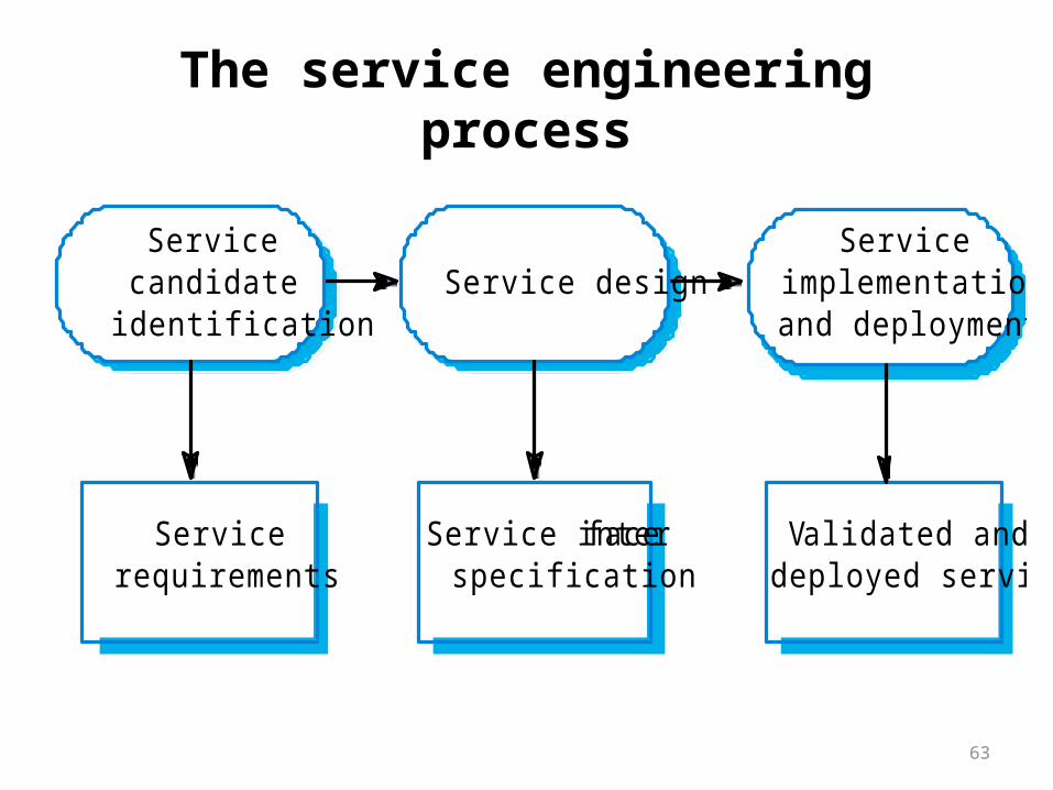
The service engineering process
Service designService
candidateidentification
Serviceimplementationand deployment
Servicerequirements
Service interfacespecification
Validated anddeployed service
64
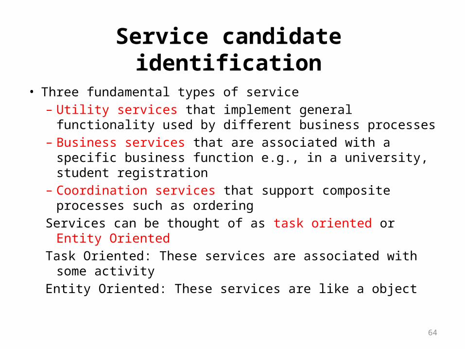
Service candidate identification• Three fundamental types of service
– Utility services that implement general functionality used by different business processes
– Business services that are associated with a specific business function e.g., in a university, student registration
– Coordination services that support composite processes such as ordering
Services can be thought of as task oriented or Entity Oriented
Task Oriented: These services are associated with some activity
Entity Oriented: These services are like a object

65
Service classificationUtility Business Coordination
Task Currency convertorEmployee locator
Validate claim formCheck credit rating
Process expense claimPay external supplier
Entity Document style checkerWeb form to XML converter
Expenses formStudent application form
Utility or business services may be entity or task oriented but co-ordination services are always task oriented
Goal of Service identification should be identify the services that are logically coherent, independent and reusable
66
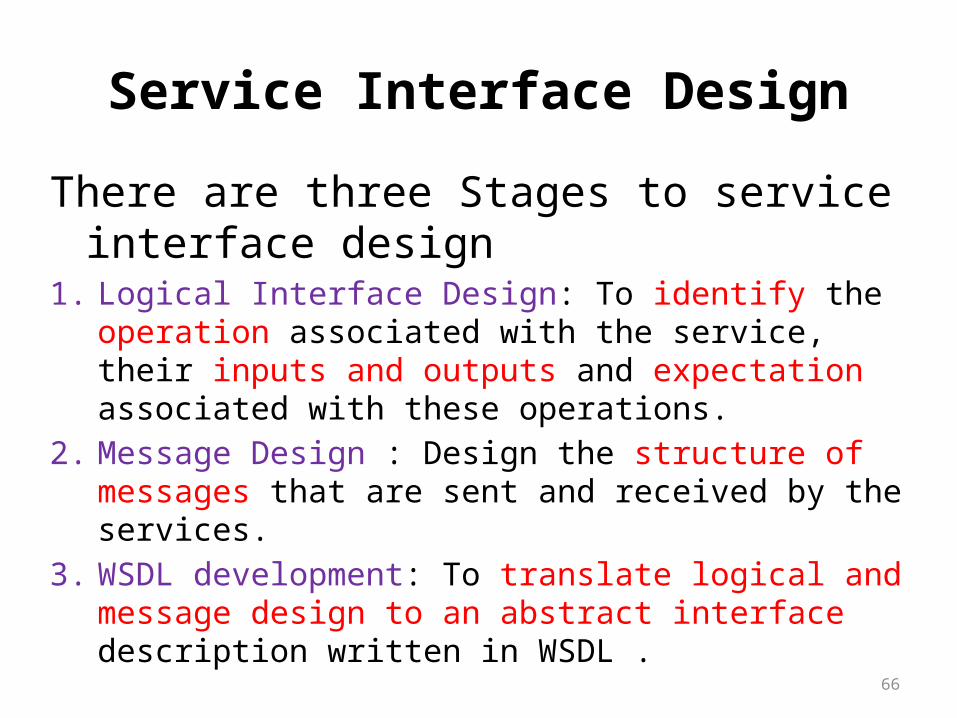
Service Interface Design
There are three Stages to service interface design1. Logical Interface Design: To identify the operation associated
with the service, their inputs and outputs and expectation associated with these operations.
2. Message Design : Design the structure of messages that are sent and received by the services.
3. WSDL development: To translate logical and message design to an abstract interface description written in WSDL .
67
Service Implementation and deployment
This is the final stage of the service engineering process .
This implementation may involve programming the service using standard programming language such as Java or c#.
Service may be developed by implementing service interface to existing component
Once service has been implemented it then has to be tested before it deployed.

68
Embedded software
Embedded software, which is used to control systems that must react to external events in their environment subject to timing constraints.
Real-time systems:• Systems which monitor and control their environment• Inevitably associated with hardware devices
– Sensors: Collect data from the system environment– Actuators: Change (in some way) the system's
environment• Time is critical. Real-time systems MUST respond within
specified times
69
Definition
• A real-time system is a software system where the correct functioning of the system depends on the results produced by the system and the time at which these results are produced
• A ‘soft’ real-time system is a system whose operation is degraded if results are not produced according to the specified timing requirements (e.g Audio/video Application)
• A ‘hard’ real-time system is a system whose operation is incorrect if results are not produced according to the timing specification (e.g Car Engine Control)
70
Stimulus/Response Systems• Given a stimulus, the system must produce a response
within a specified time• Periodic stimuli: Stimuli which occur at predictable
time intervals– For example, a temperature sensor may be polled 10
times per second• Aperiodic stimuli: Stimuli which occur at
unpredictable times– For example, a system power failure may trigger an
interrupt which must be processed by the system

71
Architectural considerations
• Because of the need to respond to timing demands made by different stimuli/responses, the system architecture must allow for fast switching between stimulus handlers.
• Timing demands of different stimuli are different so a simple sequential loop is not usually adequate.
• Real-time systems are usually designed as cooperating processes with a real-time executive controlling these processes

72
A real-time system model
Real-timecontrol system
ActuatorActuator ActuatorActuator
SensorSensorSensor SensorSensorSensor
73
System elements
• Sensors control processes– Collect information from sensors. May buffer
information collected in response to a sensor stimulus• Data processor
– Carries out processing of collected information and computes the system response
• Actuator control– Generates control signals for the actuator
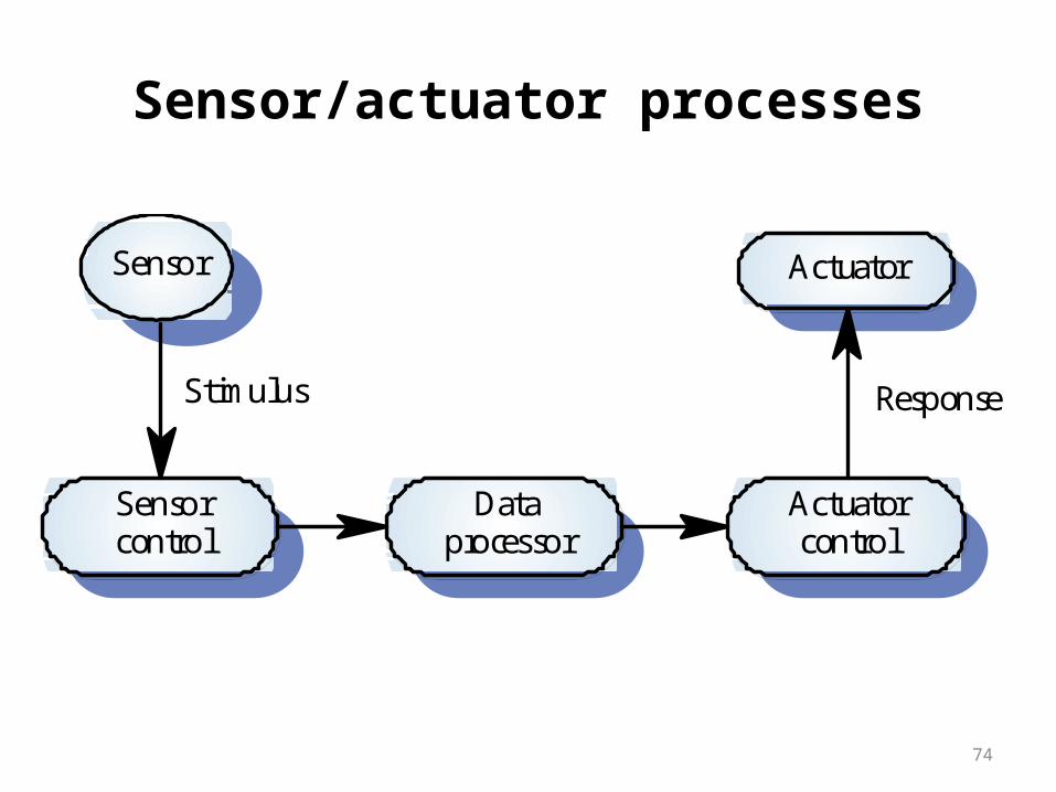
74
Sensor/actuator processes
Dataprocessor
Actuatorcontrol
Actuator
Sensorcontrol
Sensor
Stimulus Response
75
System design
• Design both the hardware and the software associated with system. Partition functions to either hardware or software
• Design decisions should be made on the basis on non-functional system requirements
• Hardware delivers better performance but potentially longer development and less scope for change
76
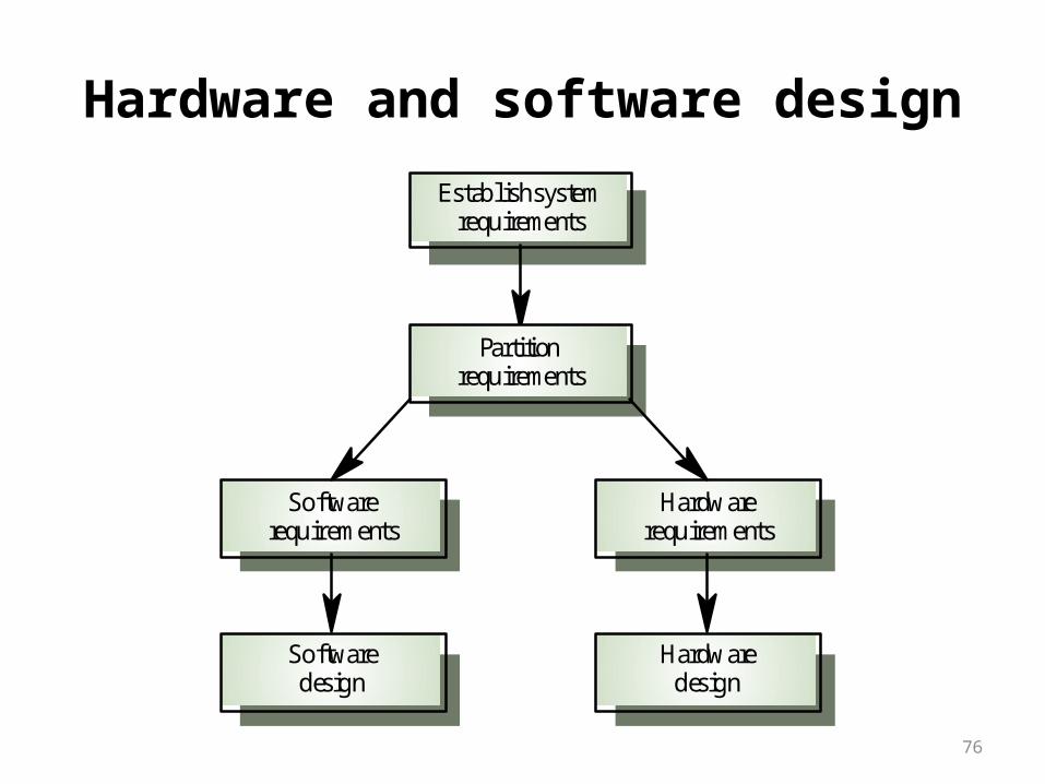
Hardware and software design
Establish systemrequirements
Partitionrequirements
Hardwarerequirements
Hardwaredesign
Softwarerequirements
Softwaredesign

77
Real Time systems design process
• Identify the stimuli to be processed and the required responses to these stimuli
• For each stimulus and response, identify the timing constraints
• Aggregate the stimulus and response processing into concurrent processes. A process may be associated with each class of stimulus and response
78
Real Time systems design process
• Design algorithms to process each class of stimulus and response. These must meet the given timing requirements
• Design a scheduling system which will ensure that processes are started in time to meet their deadlines
• Integrate using a real-time executive or operating system

79
Aspect-oriented Software Engineering
Introduction• An approach to requirements engineering that focuses on
customer concerns is consistent with aspect-oriented software development.
• Viewpoints are a way to separate the concerns of different stakeholders.
• Viewpoints represent the requirements of related groups of stakeholders.
• Cross-cutting concerns are concerns that are identified by all viewpoints.

80
Stakeholder concern
Functional concernsQuality of service concernsPolicy concernsSystem concernsOrganizational concerns

81
Cross-cutting concerns