
Unit III – Thick Cylinders€™s theory • Assumptions: • The material is homogeneous and...
44
Unit III – Thick Cylinders
Transcript of Unit III – Thick Cylinders€™s theory • Assumptions: • The material is homogeneous and...
Unit III – Thick Cylinders

Dr.P.Venkateswara Rao, Associate Professor, Dept. of Civil Engg., SVCE
2
• References:
Punmia B.C.,"Theory of Structures" (SMTS) Vol II, Laxmi Publishing Pvt Ltd, New Delhi 2004.
Rattan.S.S., "Strength of Materials", Tata McGraw Hill Education Pvt. Ltd., New Delhi, 2011.
Rajput R.K., "Strength of Materials (Mechanics of Solids)", S.Chand & company Ltd., New Delhi, 2010.
Ramamrutham S., “Theory of structures” Dhanpat Rai & Sons, New Delhi 1990.

Contents
• Thick cylinders
• Compound cylinders
Dr.P.Venkateswara Rao, Associate Professor, Dept. of Civil Engg., SVCE
3

Difference between Thick cylinder and Thin cylinder
Thick Cylinder Thin Cylinder
1.Circumferential stress varies
along the thickness of the shell.
2. Radial stress is no longer
negligible since a thick cylinder is
required to have a heavy
internal pressure.
1. Circumferential stress ‘f’ is
constant throughout the
thickness of the shell.
2.Radial stress ‘p’ is negligible in
comparison of ‘f’ and ‘f0’.
Dr.P.Venkateswara Rao, Associate Professor, Dept. of Civil Engg., SVCE
4

Lame’s theory
• Assumptions:
• The material is homogeneous and isotropic.
• Plane sections of the cylinder perpendicular to the longitudinal axis remain plane under pressure.
That is longitudinal strain is the same at all points in the cylinder
wall. (i.e., it is independent of the radius)
Hence to satisfy the requirements of uniform longitudinal strain, we
have e0 = 1
𝐸𝑓0 −
𝑓𝑥
𝑚+
𝑝𝑥
𝑚= Constant
• 𝑓𝑥 − 𝑝𝑥 = Constant = 2A (say)
𝑓𝑥 = Circumferential stress (tensile)
𝑝𝑥 = radial pressure.
Dr.P.Venkateswara Rao, Associate Professor,
Dept. of Civil Engg., SVCE 5

• Figure 1a shows a thick cylinder subjected to internal and
external radial pressure.
Lame’s theory
Dr.P.Venkateswara Rao, Associate Professor, Dept. of Civil Engg., SVCE
6
𝑓𝑥 𝑓𝑥
𝑝𝑟 𝑟
𝑅
𝑝𝑥
𝑝𝑥+𝛿𝑝𝑥
Figure 1 (a)
𝛿𝑥
𝑥
𝑝𝑥
𝑝𝑥+𝛿𝑝𝑥
𝑓𝑥𝑙𝛿𝑥 𝑓𝑥𝑙𝛿𝑥
(b)

• Consider an angular ring of the cylinder, of internal radius x and thickness δ𝑥.
• Let the internal radial pressure on this ring be 𝑝𝑥 and external pressure 𝑝 + 𝛿𝑝𝑥 .
• On any small element of this ring, 𝑓𝑥 is circumferential stress.
Lame’s theory
Dr.P.Venkateswara Rao, Associate Professor, Dept. of Civil Engg., SVCE
7
𝛿𝑥
𝑥
𝑝𝑥
𝑝𝑥+𝛿𝑝𝑥
𝑓𝑥𝑙𝛿𝑥 𝑓𝑥𝑙𝛿𝑥
(b)
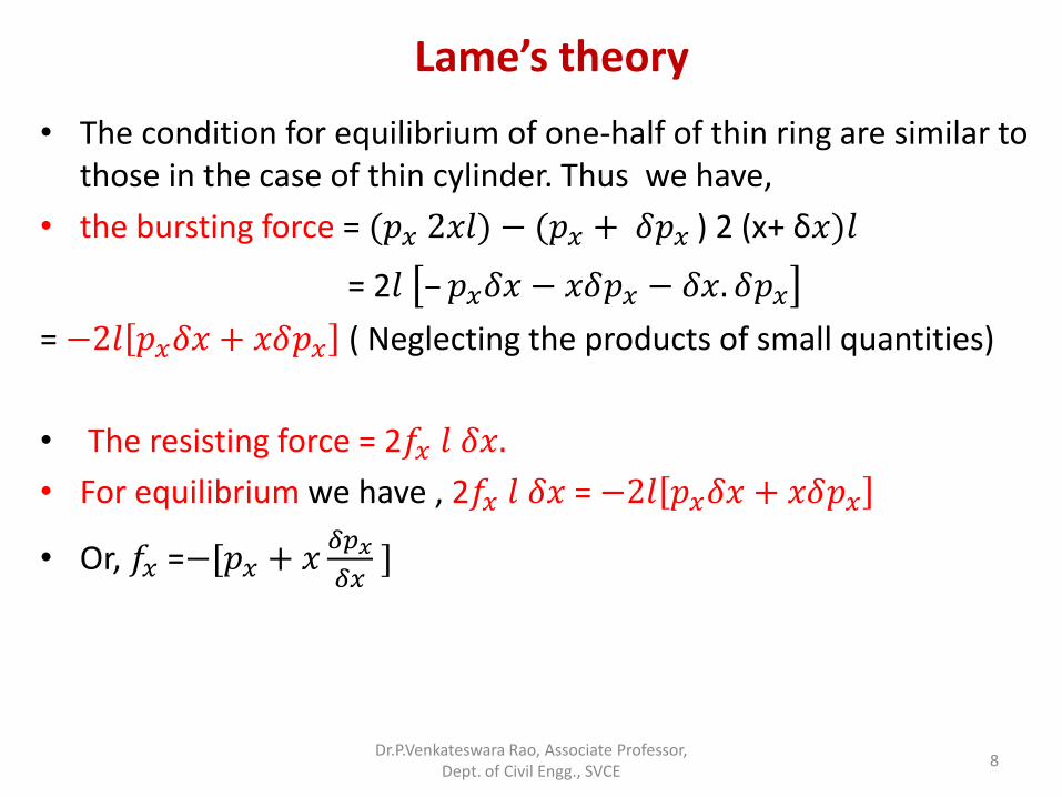
• The condition for equilibrium of one-half of thin ring are similar to those in the case of thin cylinder. Thus we have,
• the bursting force = (𝑝𝑥 2𝑥𝑙) − (𝑝𝑥 + 𝛿𝑝𝑥 ) 2 (x+ δ𝑥)𝑙
= 2𝑙 – 𝑝𝑥𝛿𝑥 − 𝑥𝛿𝑝𝑥 − 𝛿𝑥. 𝛿𝑝𝑥
= −2𝑙 𝑝𝑥𝛿𝑥 + 𝑥𝛿𝑝𝑥 ( Neglecting the products of small quantities)
• The resisting force = 2𝑓𝑥 𝑙 𝛿𝑥.
• For equilibrium we have , 2𝑓𝑥 𝑙 𝛿𝑥 = −2𝑙 𝑝𝑥𝛿𝑥 + 𝑥𝛿𝑝𝑥
• Or, 𝑓𝑥 =−[𝑝𝑥 + 𝑥𝛿𝑝𝑥
𝛿𝑥 ]
Lame’s theory
Dr.P.Venkateswara Rao, Associate Professor, Dept. of Civil Engg., SVCE
8

• In the limit when thickness of the element is reduced indefinitely,
𝑓𝑥 + 𝑝𝑥+𝑥𝑑𝑝𝑥
𝑑𝑥= 0 ------------(i)
• Another relation is obtained from the assumption that the longitudinal strain is independent of 𝑥. Thus from the equation 𝑓𝑥 − 𝑝𝑥 = 2𝐴 ---------(ii)
• And hence, 𝑓𝑥 = 𝑝𝑥 + 2𝐴 and by substituting it in equation (i), one can obtain the following relation;
(𝑝𝑥 + 2𝐴) + 𝑝𝑥+𝑥𝑑𝑝𝑥
𝑑𝑥= 0
Dr.P.Venkateswara Rao, Associate Professor, Dept. of Civil Engg., SVCE
9
Lame’s theory

• (𝑝𝑥 + 2𝐴) + 𝑝𝑥+𝑥𝑑𝑝𝑥
𝑑𝑥= 0
• or 𝑑𝑝𝑥
𝑑𝑥 =−
2 𝑝𝑥+𝐴
𝑥
•𝑑𝑝𝑥
𝑝𝑥+𝐴= −2
𝑑𝑥
𝑥
Dr.P.Venkateswara Rao, Associate Professor, Dept. of Civil Engg., SVCE
10
Lame’s theory
Integrating, log𝑒 𝑝𝑥 + 𝐴 =− log𝑒 𝑥2 + log𝑒 𝐵
Where log𝑒 𝐵 is a constant of integration.
Therefore, log𝑒 𝑝𝑥 + 𝐴 = log𝑒𝐵
𝑥2
𝑝𝑥 = 𝐵
𝑥2 – 𝐴
𝑓𝑥= 𝐵
𝑥2 + 𝐴 we know, 𝑓𝑥 − 𝑝𝑥 = 2𝐴 -----(ii) From (ii),

Problems
Problem 1.
The internal and external diameter of a thick hollow cylinder are 80 mm and 120 mm respectively. It is subjected to an external pressure of 40 N/mm2 and an internal pressure of 120 N/mm2. Calculate the circumferential and radial stresses at the mean radius.
Dr.P.Venkateswara Rao, Associate Professor, Dept. of Civil Engg., SVCE
11

• Solution:
At 𝑥 = r, 𝑝𝑟 = 120 N/mm2
i.e., at r = 40mm, 𝑝𝑟 = 120 𝑁/𝑚𝑚2
At 𝑥 = 𝑅, 𝑝𝑅 = 40 N/mm2
i.e., at R= 60 mm, 𝑝𝑅 = 40 𝑁/𝑚𝑚2
Dr.P.Venkateswara Rao, Associate Professor, Dept. of Civil Engg., SVCE
12
Problems

• Lame’s equations are:
• 𝑝𝑥 = 𝐵
𝑥2 – 𝐴 −− − (1)
• 𝑓
𝑥 =
𝐵
𝑥2 + 𝐴 −− −(2)
Where 𝑝𝑥 = radial stress at a radius x from the centre of the cylinder.
𝑓𝑥 = circumferential stress at a radius ‘x’ from the centre of the cylinder
Dr.P.Venkateswara Rao, Associate Professor, Dept. of Civil Engg., SVCE
13
Problems

From equation (1),
• At 𝑥 = 𝑟, 𝑝𝑟 = 𝐵
𝑟2 – 𝐴 -----------(1a)
• At 𝑥 = 𝑅, 𝑝𝑅= 𝐵
𝑅2 – 𝐴 ----------------(1b)
• From (1a), 120 = 𝐵
402 − 𝐴
• From (1b), 40 = 𝐵
602 − 𝐴
• ------------------------------
• (1a) – (1b), 80 = B 1
402 −1
602
Dr.P.Venkateswara Rao, Associate Professor, Dept. of Civil Engg., SVCE
14
Problems

• B= 80∗ 402∗602
602−402 = 230400
• From (1a), 120 = 230400
402 − 𝐴
• 120 = 144 − 𝐴
• A= 24
• Radial stress at the mean radius ‘50 mm’ is:
• 𝑝50 =𝐵
502 – 𝐴
= 230400
502 − 24 = 68.16 N/mm2
Dr.P.Venkateswara Rao, Associate Professor, Dept. of Civil Engg., SVCE
15
Problems

• Circumferential stress at mean radius ’50 mm’ is,
• 𝑓50 = 𝐵
502 +𝐴
= 230400
502 + 24 = 116.16 N/mm2
Dr.P.Venkateswara Rao, Associate Professor, Dept. of Civil Engg., SVCE
16
Problems
∴ 𝑝50 = 68.16 N/mm2 and 𝑓50=116.16 N/mm2
120 N/mm2
40 N/mm2
88 N/mm2
168 N/mm2
116.16 N/mm2
68.16 N/mm2
𝑝𝑥
𝑓𝑥 𝑝𝑟 = 120 𝑁/𝑚𝑚2 𝑝𝑅 = 40 𝑁/𝑚𝑚2
𝑓𝑟 = 168 𝑁/𝑚𝑚2 𝑓𝑅 = 88 𝑁/𝑚𝑚2

Problem 2
A cylinder has an internal radius of 200 mm and external radius of 300 mm. Permissible stress for the material is 15.5 N/mm2. If the cylinder is subjected to an external pressure of 4 N/mm2, find the internal pressure that can be applied.
Dr.P.Venkateswara Rao, Associate Professor, Dept. of Civil Engg., SVCE
17
Problems

• Solution: r =20 mm; R= 300mm,
• 𝑓𝑟 = 15.5 N/mm2 ; 𝑝𝑅 = 4𝑁/𝑚𝑚2
• Lame’s equations are:
𝑝𝑥 = 𝐵
𝑥2 – 𝐴 −− − (1)
𝑓
𝑥 =
𝐵
𝑥2 + 𝐴 −− −(2)
From (1), 𝑝𝑅 = 𝐵
𝑅2 – 𝐴
4 = 𝐵
3002 − 𝐴 ---------------(1a)
Dr.P.Venkateswara Rao, Associate Professor,
Dept. of Civil Engg., SVCE 18
Problems

• From (2), 𝑓
𝑟 =
𝐵
𝑟2 + 𝐴
15.5 = 𝐵
2002 + 𝐴 ----------------(2a)
4 = 𝐵
3002 − 𝐴 ---------------(1a)
________________________________
(1a) + (2a), 19.5 = B 1
3002 +1
2002
• B= 19.5∗ 3002∗2002
2002+3002 = 540000
Dr.P.Venkateswara Rao, Associate Professor,
Dept. of Civil Engg., SVCE 19
Problems

• From (1a), 4= 540000
3002 − 𝐴
• A = 6-4 = 2
• Internal pressure, 𝑝𝑟 = 𝐵
𝑟2 – 𝐴
= 540000
2002 − 2 = 11.5 𝑁/𝑚𝑚2
Dr.P.Venkateswara Rao, Associate Professor, Dept. of Civil Engg., SVCE
20
Problems

Problem 3
A pipe with internal diameter 400 mm is to carry a fluid pressure of 12 MPa. If the maximum stress in the material of the pipe is restricted to 110 MPa, calculate the minimum thickness of the pipe required.
Dr.P.Venkateswara Rao, Associate Professor, Dept. of Civil Engg., SVCE
21
Problems

• Solution:
• d= 400 mm, r = 200 mm
• 𝑝𝑟 = 12 𝑀𝑃𝑎 = 12 𝑁/𝑚𝑚2
• 𝑓𝑟 = 110 𝑀𝑃𝑎 = 140 𝑁/𝑚𝑚2
• Lame’s equations:
• 𝑝𝑥 = 𝐵
𝑥2 – 𝐴 −− − (1)
• 𝑓
𝑥 =
𝐵
𝑥2 + 𝐴 −− −(2)
• From (1), 𝑝𝑟 = 𝐵
𝑟2 – 𝐴
Dr.P.Venkateswara Rao, Associate Professor,
Dept. of Civil Engg., SVCE 22
Problems

• 12 = 𝐵
2002 − 𝐴 ---------------(1a)
• From (2), 𝑓
𝑟 =
𝐵
𝑟2 + 𝐴
110 = 𝐵
2002 + 𝐴 ----------------(2a)
12 = 𝐵
2002 − 𝐴 ---------------(1a)
___________________________________
(2a) +(1a) is, 122= 2𝐵
2002
Dr.P.Venkateswara Rao, Associate Professor, Dept. of Civil Engg., SVCE
23
Problems
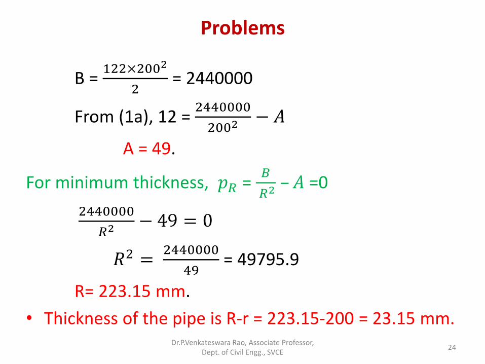
B = 122×2002
2 = 2440000
From (1a), 12 = 2440000
2002 − 𝐴
A = 49.
For minimum thickness, 𝑝𝑅 = 𝐵
𝑅2 – 𝐴 =0
2440000
𝑅2 − 49 = 0
𝑅2 = 2440000
49 = 49795.9
R= 223.15 mm.
• Thickness of the pipe is R-r = 223.15-200 = 23.15 mm.
Dr.P.Venkateswara Rao, Associate Professor, Dept. of Civil Engg., SVCE
24
Problems
• Problem 4
A pipe with internal diameter 400 mm is to carry a fluid at a pressure of 10 MPa. If the maximum stress in the material of the pipe is restricted to 150 MPa, calculate the minimum thickness of the pipe required.
Dr.P.Venkateswara Rao, Associate Professor, Dept. of Civil Engg., SVCE
25
Problems

• Solution:
d= 400 mm
r = 200 mm
𝑝𝑟 = 10 𝑀𝑃𝑎 = 10 𝑁/𝑚𝑚2
𝑓𝑟 = 150 𝑀𝑃𝑎 = 150 𝑁/𝑚𝑚2
• Lame’s equations:
𝑝𝑟 = 𝐵
𝑟2 – 𝐴 −− − (1)
𝑓
𝑟 =
𝐵
𝑟2 + 𝐴 −− −(2)
Dr.P.Venkateswara Rao, Associate Professor, Dept. of Civil Engg., SVCE
26
Problems
400 mm
Pr=10 MPa
fr = 150 MPa

From (1), 10 = 𝐵
2002 − 𝐴 ---------------(1a)
From (2), 150 = 𝐵
2002 + 𝐴 ----------------(2a)
_____________________________________
(1a) + (2a), 160 = 2𝐵
2002
and hence, B = 160×2002
2 = 320× 104
From (1a), 10 = 320 ×104
2002 − 𝐴
A = 70.
Since PR = 0,
Dr.P.Venkateswara Rao, Associate Professor,
Dept. of Civil Engg., SVCE 27
Problems

• Since PR = 0,
𝐵
𝑅2 – 𝐴 =0
•320 ×104
𝑅2 − 70 = 0
• R2 = 320 ×104
𝑅2 = 45714.2
• R=213.8
• Thickness of pipe = R-r = 213.8-200 = 13.8 mm.
Dr.P.Venkateswara Rao, Associate Professor, Dept. of Civil Engg., SVCE
28
Problems

• In the thick cylinders when the cylindrical shells subjected to internal pressure, the circumferential stress (hoop stress) is maximum at inner circumference and it is decreases towards the outer circumference.
• Hence the maximum pressure inside the shell is limited corresponding to the condition that the hoop stress at the inner circumference reaches the permissible value.
Dr.P.Venkateswara Rao, Associate Professor,
Dept. of Civil Engg., SVCE 29
Compound Cylinders
𝑝𝑥
𝑓𝑥

• But suppose the shell is made of shrinking one tube over the other. This will initially introduce hoop compressive stresses in the inner tube and hoop tensile stresses in the outer tube.
• If now the compound tube is subjected to internal pressure, both the inner and outer tubes will be subjected to hoop tensile stress, due to internal pressure alone.
Dr.P.Venkateswara Rao, Associate Professor, Dept. of Civil Engg., SVCE
30
Compound Cylinders
𝑟1
𝑟2 𝑟3

• Adding the internal stresses caused while shrinking and the stresses due to internal pressure alone, the final hoop stresses in both the tubes can be determined .
• By this arrangement the hoop stresses throughout the metal will be more or less uniform.
Dr.P.Venkateswara Rao, Associate Professor, Dept. of Civil Engg., SVCE
31
Compound Cylinders
𝑟1
𝑟2 𝑟3
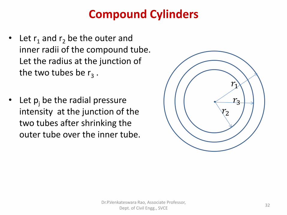
• Let r1 and r2 be the outer and inner radii of the compound tube. Let the radius at the junction of the two tubes be r3 .
• Let pj be the radial pressure intensity at the junction of the two tubes after shrinking the outer tube over the inner tube.
Dr.P.Venkateswara Rao, Associate Professor, Dept. of Civil Engg., SVCE
32
Compound Cylinders
𝑟1
𝑟2 𝑟3

• Let Lamme’s relation for the outer tube be given by,
• 𝑝𝑥 =𝑏1
𝑥2 − 𝑎1
• and 𝑓𝑥 =𝑏1
𝑥2 + 𝑎1
• At 𝑥 = 𝑟1, 𝑝𝑥 = 0
• ∴ 0 =𝑏1
𝑟12 − 𝑎1 -----(1)
and at 𝑥 = 𝑟3,
𝑝𝑗 =𝑏1
𝑟32 − 𝑎1--------(2)
The constants 𝑎1 and 𝑏1 can be
determined from equations (1) and (2).
Dr.P.Venkateswara Rao, Associate Professor, Dept. of Civil Engg., SVCE
33
Compound Cylinders
𝑟1
𝑟2 𝑟3
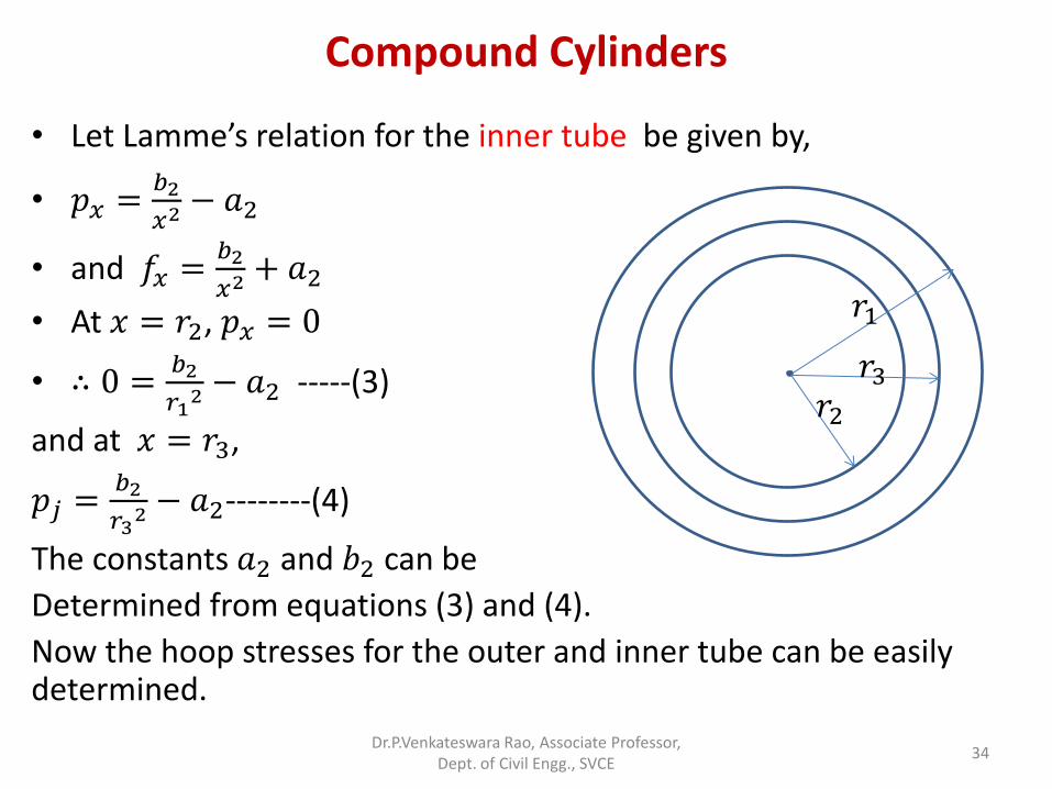
• Let Lamme’s relation for the inner tube be given by,
• 𝑝𝑥 =𝑏2
𝑥2 − 𝑎2
• and 𝑓𝑥 =𝑏2
𝑥2 + 𝑎2
• At 𝑥 = 𝑟2, 𝑝𝑥 = 0
• ∴ 0 =𝑏2
𝑟12 − 𝑎2 -----(3)
and at 𝑥 = 𝑟3,
𝑝𝑗 =𝑏2
𝑟32 − 𝑎2--------(4)
The constants 𝑎2 and 𝑏2 can be
Determined from equations (3) and (4).
Now the hoop stresses for the outer and inner tube can be easily determined.
Dr.P.Venkateswara Rao, Associate Professor, Dept. of Civil Engg., SVCE
34
Compound Cylinders
𝑟1
𝑟2 𝑟3

• Suppose the compound tube is subjected to an internal fluid pressure 𝑝0. For this analysis , the inner and the outer tubes will together be considered as one thick shell. The stresses due to internal fluid pressure alone can now be determined. For this condition let Lame’s relations be,
• 𝑝𝑥 =𝐵
𝑥2 − 𝐴
• and 𝑓𝑥 =𝐵
𝑥2 + 𝐴
• At 𝑥 = 𝑟1, 𝑝𝑥 = 0
• ∴ 0 =𝐵
𝑟12 − 𝐴 -----(5)
and at 𝑥 = 𝑟2,
𝑝0 =𝐵
𝑟22 − 𝐴--------(6)
The constants 𝐴 and 𝐵 can now be evaluated. Dr.P.Venkateswara Rao, Associate Professor,
Dept. of Civil Engg., SVCE 35
Compound Cylinders
𝑟1
𝑟2 𝑟3
𝑝0

The hoop stresses across the section can now be easily determined.
By algebraically adding, the hoop stresses caused due to shrinking to the hoop stresses caused by internal fluid pressure, the final hoop stresses may be determined.
Dr.P.Venkateswara Rao, Associate Professor, Dept. of Civil Engg., SVCE
36
Compound Cylinders
𝑟1
𝑟2 𝑟3

Problem:
A compound tube is composed of a tube 25 cm internal diameter and 2.5 cm thick shrunk on a tube of 25 cm external diameter and 2.5 cm thick. The radial pressure at the junction is 80 kg/cm2 . The compound tube is subjected to an internal fluid pressure of 845 kg/cm2. Find the variation of the hoop stress over the wall of the compound tube.
Dr.P.Venkateswara Rao, Associate Professor, Dept. of Civil Engg., SVCE
37
Compound Cylinders - Problems

Solution:
Stresses due to shrinking the outer tube to the inner tube:
Outer tube: Let Lamme’s relations for the outer tube be given by,
• 𝑝𝑥 =𝑏1
𝑥2 − 𝑎1
• and 𝑓𝑥 =𝑏1
𝑥2 + 𝑎1
• At 𝑥 = 15 𝑐𝑚, 𝑝𝑥 = 0
• ∴ 0 =𝑏1
152 − 𝑎1 -----(1)
and at 𝑥 = 12.5 𝑐𝑚, 𝑝𝑗 = 80 kg/cm2
80 =𝑏1
12.52 − 𝑎1--------(2)
Solving equations (1) and (2), we get 𝑎1=181.8 and 𝑏1=40910
Dr.P.Venkateswara Rao, Associate Professor,
Dept. of Civil Engg., SVCE 38
Compound Cylinders - Problems
12.5 𝑐𝑚
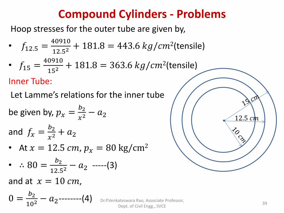
Hoop stresses for the outer tube are given by,
• 𝑓12.5 =40910
12.52 + 181.8 = 443.6 𝑘𝑔/𝑐𝑚2(tensile)
• 𝑓15 =40910
152 + 181.8 = 363.6 𝑘𝑔/𝑐𝑚2(tensile)
Inner Tube:
Let Lamme’s relations for the inner tube
be given by, 𝑝𝑥 =𝑏2
𝑥2 − 𝑎2
and 𝑓𝑥 =𝑏2
𝑥2 + 𝑎2
• At 𝑥 = 12.5 𝑐𝑚, 𝑝𝑥 = 80 kg/cm2
• ∴ 80 =𝑏2
12.52 − 𝑎2 -----(3)
and at 𝑥 = 10 𝑐𝑚,
0 =𝑏2
102 − 𝑎2--------(4)
Dr.P.Venkateswara Rao, Associate Professor, Dept. of Civil Engg., SVCE
39
Compound Cylinders - Problems
12.5 𝑐𝑚

Solving equations (3) and (4) we get 𝑎2 = −222 and 𝑏2 = −22220
Hence the hoop stresses for the inner tube are given by,
• 𝑓12.5 = −22220
12.52 − 222 = −364.2 𝑘𝑔/𝑐𝑚2(Compressive)
• 𝑓10 = −22220
102 − 222 = −444.2 𝑘𝑔/𝑐𝑚2(Compressive)
Stresses due to internal fluid pressure alone:
For this condition both the tubes together will
Be considered as acting as one cylinder.
Let Lamme’s relations for this condition be
• 𝑝𝑥 =𝐵
𝑥2 − 𝐴
• and 𝑓𝑥 =𝐵
𝑥2 + 𝐴
Dr.P.Venkateswara Rao, Associate Professor,
Dept. of Civil Engg., SVCE 40
Compound Cylinders - Problems
12.5 𝑐𝑚
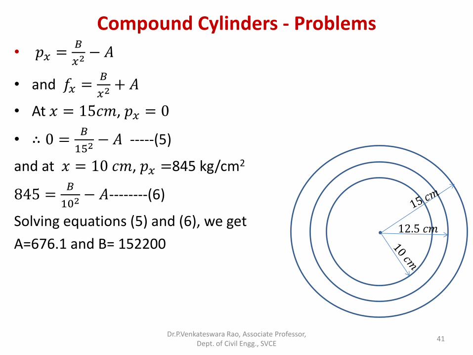
• 𝑝𝑥 =𝐵
𝑥2 − 𝐴
• and 𝑓𝑥 =𝐵
𝑥2 + 𝐴
• At 𝑥 = 15𝑐𝑚, 𝑝𝑥 = 0
• ∴ 0 =𝐵
152 − 𝐴 -----(5)
and at 𝑥 = 10 𝑐𝑚, 𝑝𝑥 =845 kg/cm2
845 =𝐵
102 − 𝐴--------(6)
Solving equations (5) and (6), we get
A=676.1 and B= 152200
Dr.P.Venkateswara Rao, Associate Professor, Dept. of Civil Engg., SVCE
41
Compound Cylinders - Problems
12.5 𝑐𝑚

Hence the hoop stresses due to internal
fluid pressure alone given by
• 𝑓10 =152200
102 + 676.1 = 2198.1𝑘𝑔/𝑐𝑚2(Tensile)
• 𝑓12.5 =152200
12.52 + 676.1 = 1650.1 𝑘𝑔/𝑐𝑚2(Tensile)
• 𝑓15 =152200
152 + 676.1 = 1352.2 𝑘𝑔/𝑐𝑚2(Tensile)
Hence due to the combined effect of shrinking the outer tube on the innner tube and internal fluid pressure the final hoop stresses will be as follows:
Outer tube: 𝐹15 = 363.6 + 1352.2 = 1715.8 kg/cm2 (tensile)
𝐹12.5 = 443.6 + 1650.1 = 2093.7 kg/cm2 (tensile)
Inner tube: 𝐹12.5 = −364.2 + 1650.1 = 1285.9 kg/cm2 (tensile)
𝐹10 = −444.2 + 2198.1 = 1753.9 kg/cm2 (tensile)
Dr.P.Venkateswara Rao, Associate Professor, Dept. of Civil Engg., SVCE
42
Compound Cylinders - Problems

Initial difference in radii at junction is 𝜹𝒓′: 𝛿𝑟′
𝑟′=
1
𝐸
𝐵′
𝑟32
+ 𝐴′ −𝐵
𝑟32
+ 𝐴
Let the Lame’s equations for inner tube be
𝑝𝑥 =𝐵
𝑥2− A; 𝑓𝑥 =
𝐵
𝑥2+ A
and for the outer tube be
𝑝𝑥 =𝐵′
𝑥2 − 𝐴′; 𝑓𝑥 =𝐵′
𝑥2 + 𝐴′
Dr.P.Venkateswara Rao, Associate Professor, Dept. of Civil Engg., SVCE
43
Compound Cylinders
𝑟1
𝑟2 𝑟3

A thick cylinder of external diameter 40 cm and internal diameter 30 cm is shrunk on to another cylinder of external diameter 30 cm and 5 cm thick. If the radial pressure at the junction to shrink fit is 15 Mpa, calculate the initial difference in radii at the junction.
Dr.P.Venkateswara Rao, Associate Professor, Dept. of Civil Engg., SVCE
44
Compound Cylinders - Problems


