UNIT II SPREAD SPECTRUM COMMUNICATION 2 marks 1. 2. YEAR/COMMUNICATION... · UNIT II SPREAD...
29
1 UNIT II SPREAD SPECTRUM COMMUNICATION 2 marks 1. Define spread spectrum Spread-spectrum techniques are methods by which a signal (e.g. an electrical, electromagnetic, or acoustic signal) generated in a particular bandwidth is deliberately spread in the frequency domain, resulting in a signal with a wider bandwidth. These techniques are used for establishment of secure communications, increasing resistance to natural interference and jamming, to prevent detection, and to limit power flux density (e.g. in satellite downlinks). 2. Mention the Spread Spectrum System Criteria The following two criteria must be satisfied: i. The transmitted signal must occupy a bandwidth much greater than the bandwidth of the modulating signal (i.e. the input signal to the system). ii. The bandwidth occupied by the transmitted signal must be determined by a prescribed waveform and not by the modulating frequency (i.e. carrier frequency) 3. Give the reasons for use of spread spectrum systems. There are three major reasons for the use of spread spectrum techniques in communication systems today. i. They aid privacy of the transmission, since the spectral density of the spread spectrum may be less than the noise spectral density of the receiver. ii. The despreading process in the receiver will spread the spectra of unwanted narrowband signals, thus improving interference rejection. iii. The effect on a spread spectrum receiver, that receives a spread spectrum from a different spread spectrum system using the same frequency bands but implementing a different spreading pattern, approximates to noise in the receiver. 4.Give the necessary bandwidth equation for error-free transmission information at very low SNR. w NC B S where C is the capacity of a communication channel in bits per hertz, B w is the bandwidth in hertz, S is the signal power, and N is the noise power.
Transcript of UNIT II SPREAD SPECTRUM COMMUNICATION 2 marks 1. 2. YEAR/COMMUNICATION... · UNIT II SPREAD...

1
UNIT II
SPREAD SPECTRUM COMMUNICATION
2 marks
1. Define spread spectrum
Spread-spectrum techniques are methods by which a signal (e.g. an electrical,
electromagnetic, or acoustic signal) generated in a particular bandwidth is deliberately spread in
the frequency domain, resulting in a signal with a wider bandwidth. These techniques are used
for establishment of secure communications, increasing resistance to natural interference and
jamming, to prevent detection, and to limit power flux density (e.g. in satellite downlinks).
2. Mention the Spread Spectrum System Criteria
The following two criteria must be satisfied:
i. The transmitted signal must occupy a bandwidth much greater than the bandwidth of the
modulating signal (i.e. the input signal to the system).
ii. The bandwidth occupied by the transmitted signal must be determined by a prescribed
waveform and not by the modulating frequency (i.e. carrier frequency)
3. Give the reasons for use of spread spectrum systems.
There are three major reasons for the use of spread spectrum techniques in communication
systems today.
i. They aid privacy of the transmission, since the spectral density of the spread spectrum
may be less than the noise spectral density of the receiver.
ii. The despreading process in the receiver will spread the spectra of unwanted narrowband
signals, thus improving interference rejection.
iii. The effect on a spread spectrum receiver, that receives a spread spectrum from a different
spread spectrum system using the same frequency bands but implementing a different
spreading pattern, approximates to noise in the receiver.
4.Give the necessary bandwidth equation for error-free transmission information at very
low SNR.
w
NCB
S
where C is the capacity of a communication channel in bits per hertz, Bw is the bandwidth in
hertz, S is the signal power, and N is the noise power.

2
5. Mention the conventional systems used before spread spectrum
i. WHYN, coined by Harvey, stands for Wobbulated HYperbolic Navigation.
ii. LORAN (LOng RAnge Navigation) was eventually won by Sperry Gyroscope
Company‘s CYTAC. Developed in the early 1950s, the CYTAC system and its
CYCLAN predecessor had many of the attributes of WHYN, but signal-wise, CYTAC
was different in two regards. First, pulse modulation was used so that earliest arriving sky
waves could be rejected by gating, and second, phase coding of the pulses was innovated
to reject multihop sky waves.
iii. Madison Nicholson of Sylvania Buffalo headed a proposal effort for the study of a
communication system which he called ―Hush-Up.‖
iv. To slew the time base in the Hush-Up receiver, Nicholson‘s ―linear modulator‖ (or ―cycle
adder‖) was an essential part of another system which Jim Green named the Buffalo
Laboratories Application of Digitally Exact Spectra, or BLADES for short.
v. The acronym NOMAC, classified confidential at the time and standing for ―NOise
Modulation and Correlation,‖ was coined by Bennett Basore,
vi. The prototype SR-NOMAC system developed for the Army Signal Corps by Lincoln
Laboratory was called the F9C.
6. What are the three ways to spread the bandwidth of the signal?
i. Direct sequence. The digital data is directly coded at a much higher frequency. The code
is generated pseudo-randomly, the receiver knows how to generate the same code, and
correlates the received signal with that code to extract the data.
ii. Frequency hopping. The signal is rapidly switched between different frequencies within
the hopping bandwidth pseudo-randomly, and the receiver knows beforehand where to
find the signal at any given time.
iii. Time hopping. The signal is transmitted in short bursts pseudo-randomly, and the
receiver knows beforehand when to expect the burst.
7. Define DSSS.
Direct-sequence spread spectrum (DSSS) is a spread spectrum modulation technique in which
the transmitted signal takes up more bandwidth than the information signal that is being
modulated. The name 'spread spectrum' comes from the fact that the carrier signals occur over
the full bandwidth (spectrum) of a device's transmitting frequency.
8. How signals are transmitted in DSSS?
Direct-sequence spread-spectrum transmissions multiply the data being transmitted by a
"noise" signal. This noise signal is a pseudorandom sequence of 1 and −1 values, at a
frequency much higher than that of the original signal, thereby spreading the energy of the
original signal into a much wider band.

3
If an undesired transmitter transmits on the same channel but with a different PN sequence (or
no sequence at all), the de-spreading process results in no processing gain for that signal. This
effect is the basis for the code division multiple access (CDMA) property of DSSS, which
allows multiple transmitters to share the same channel within the limits of the cross-correlation
properties of their PN sequences.
9. Give the feature of DSSS.
1. DSSS phase-modulates a sine wave pseudorandomly with a continuous string of
pseudonoise (PN) code symbols called "chips", each of which has a much shorter
duration than an information bit. That is, each information bit is modulated by a sequence
of much faster chips. Therefore, the chip rate is much higher than the information signal
bit rate.
2. DSSS uses a signal structure in which the sequence of chips produced by the transmitter
is known a priori by the receiver. The receiver can then use the same PN sequence to
counteract the effect of the PN sequence on the received signal in order to reconstruct the
information signal.
10. What are the benefits of DSSS?
i. Resistance to intended or unintended jamming
ii. Sharing of a single channel among multiple users
iii. Reduced signal/background-noise level hampers interception (stealth)
iv. Determination of relative timing between transmitter and receiver
12. Define the term pseudo random noise
A Pseudo-random Noise (PN) sequence is a sequence of binary numbers, e.g. ±1, which
appears to be random; but is in fact perfectly deterministic. The sequence appears to be random
in the sense that the binary values and groups or runs of the same binary value occur in the
sequence.
Linear feedback shift register (LFSR). LFSRs are one of the simplest ways to generate
pseudorandom sequences. In an LFSR, any bit is determined by a linear combination of the
previous n bits, for a suitable choice of n. In particular, we may have an LFSR in which
Bn = A0B0 ⊕ A1B1 ⊕ A2B2 ⊕ . . . ⊕ An−1Bn−1.

4
11. Define FHSS.
Frequency-hopping spread spectrum (FHSS) is a method of transmitting radio signals by
rapidly switching a carrier among many frequency channels, using a pseudorandom sequence
known to both transmitter and receiver. It is utilized as a multiple access method in the
frequency-hopping code division multiple access (FH-CDMA) scheme.
12. Give the advantages of FHSS
A spread-spectrum transmission offers three main advantages over a fixed-frequency
transmission:
1.Spread-spectrum signals are highly resistant to narrowband interference. The process of re-
collecting a spread signal spreads out the interfering signal, causing it to recede into the
background.
2.Spread-spectrum signals are difficult to intercept. An FHSS signal simply appears as an
increase in the background noise to a narrowband receiver. An eavesdropper would only be
able to intercept the transmission if the pseudorandom sequence was known.
3.Spread-spectrum transmissions can share a frequency band with many types of
conventional transmissions with minimal interference. The spread-spectrum signals add
minimal noise to the narrow-frequency communications, and vice versa. As a result,
bandwidth can be utilized more efficiently.
13. Give the applications of FHSS
Spread-spectrum signals are highly resistant to deliberate jamming, unless the adversary has
knowledge of the spreading characteristics. Military radios use cryptographic techniques to
generate the channel sequence under the control of a secret Transmission Security Key
(TRANSEC) that the sender and receiver share.
By itself, frequency hopping provides only limited protection against eavesdropping and
jamming. To get around this weakness most modern military frequency hopping radios often
employ separate encryption devices such as the KY-57. U.S. military radios that use frequency
hopping include HAVE QUICK and SINCGARS.
14. Give the various types of FHSS
i. Adaptive Frequency-hopping spread spectrum (AFH) (as used in Bluetooth) improves
resistance to radio frequency interference by avoiding using crowded frequencies in the
hopping sequence. This sort of adaptive transmission is easier to implement with FHSS
than with DSSS.
ii. The key idea behind AFH is to use only the ―good‖ frequencies, by avoiding the "bad"
frequency channels -- perhaps those "bad" frequency channels are experiencing
frequency selective fading, or perhaps some third party is trying to communicate on those

5
bands, or perhaps those bands are being actively jammed. Therefore, AFH should be
complemented by a mechanism for detecting good/bad channels.
iii. However, if the radio frequency interference is itself dynamic, then the strategy of ―bad
channel removal‖, applied in AFH might not work well. For example, if there are several
colocated frequency-hopping networks (as Bluetooth Piconet), then they are mutually
interfering and the strategy of AFH fails to avoid this interference.
iv. In this case, there is a need to use strategies for dynamic adaptation of the frequency
hopping pattern. Such a situation can often happen in the scenarios that use unlicensed
spectrum.
v. In addition, dynamic radio frequency interference is expected to occur in the scenarios
related to cognitive radio, where the networks and the devices should exhibit frequency-
agile operation.
vi. Chirp modulation can be seen as a form of frequency-hopping that simply scans through
the available frequencies in consecutive order.
15. Give the advantages and disadvantages of Spread Spectrum Techniques
The advantages of spread spectrum techniques as applied to communication systems can be as
follows:
i. All types: Multiple usage by different user groups, as each user group can be allocated a
different PN code.This code is the key necessary to unlock the message from the system.
Without this key it is very difficult, almost impossible to extract the information. A
spread spectrum will see another spread spectrum signal as interference and reject it as it
would for a narrowband signal.
ii. Frequency hopping: A narrow band will only cause minimal interference on the
wideband signal. Frequency jamming is extremely difficult and can only be effectively
achieved if the jamming receiver has the same PN code and channel allocation. The
greater the hop set, the smaller the dwell time and the greater the bandwidth the smaller
the interference from narrowband signals.
iii. Frequency hopping and direct sequence: The output power of the spread spectrum is
spread over a large bandwidth. This means that the spectrum has a very low spectral
density; 1W output power over an 8 MHz band gives a spectral density of 1.25 nW/Hz.
These systems are particularly useful to the military and police. The low spectral density
may not even be recognized as valid communication, thus leading to low probability of
interception and recognition.
Disadvantages of spread spectrum techniques are:
1.Complex circuitry 2.expensive to develop 3.Very large bandwidth
4.Easily jammed and hence is not generally used in its true form.

6
16. Advantages of Spread spectrum over a fixed-frequency transmission
Spread-spectrum signals are highly resistant to narrowband interference. The process of
re-collecting a spread signal spreads out the interfering signal, causing it to recede into
the background.
Spread-spectrum signals are difficult to intercept. A spread-spectrum signal may simply
appear as an increase in the background noise to a narrowband receiver. An eavesdropper
may have difficulty intercepting a transmission in real time if the pseudorandom
sequence is not known.
Spread-spectrum transmissions can share a frequency band with many types of
conventional transmissions with minimal interference. The spread-spectrum signals add
minimal noise to the narrow-frequency communications, and vice versa. As a result,
bandwidth can be used more efficiently.

7
UNIT 2
SPREAD SPECTRUM SYSTEM
SPREAD SPECTRUM TECHNIQUES:
In spread spectrum system the transmitted signal is spread over a wide frequency band
i.e., it takes a baseband signal with a bandwidth of only a few kHz and distributes it over a band
that may be many MHz wide. This spreading is done by, sometimes called as a code signal
which is independent of data. In Code Division Multiple Access (CDMA) systems all users
transmits in the same bandwidth simultaneously. Communication systems following this concept
are referred as ―Spread Spectrum Systems‖.
The codes used for spreading have low cross-correlation values and are unique to every
user. This is the reason that a receiver has knowledge about the code of the intended transmitter
and is capable of selecting the desired signals.
Advantages of Spread Spectrum:
Low power spectral density: As the signal is spread over a large frequency band, the
power spectral density is getting very small, so other communication systems do not
suffer from this kind of communications. Hence the Gaussian noise level is increasing.
Interference limited operation: In all situations the whole frequency spectrum is used.
Privacy due to unknown random codes: The applied codes in principle are known to a
hostile user. This means that it is hardly possible to detect the message of other user.
Applying spread spectrum implies the reduction of multipath effects.
Random access possibilities: User can start their transmission at any arbitrary time.
Good anti-jam performance.
Types of Spread Spectrum:
There are three types of spread spectrum technique can be used and these are;
Direct Sequence
Frequency hopping
Process Gain and Jam Margin:
Process gain and Jam margin are the basic properties of spread spectrum communication
systems.
The process gain is defined as the difference between the output and input signal to noise
ratio. Alternatively, it is the ratio of transmission bandwidth and information bandwidth.
GP =BWrf
Rinf (1)
where BWrf – RF bandwidth of the transmitted spread spectrum signal
Rinf – Data rate in the information baseband channel
Process gain is basically the spreading factor. The process gain determines;

8
The number of users that can be allowed in a system.
The amount of multipath effect reduction.
The difficulty to jam or detect a signal etc.
For spread spectrum systems it is advantageous to have a processing gain as high as possible.
Jam margin express the capability of a system to perform in interfering environment. It takes
cure for a useful system output signal to noise ratio and allows for internal losses. It can be
calculated by the formula:
Mj = GP − Lsys + S
N
out (2)
where Mj-=Jamming margin
GP-Process Gain
Lsys – System implementation losses
S
N
out - Output Signal to noise ratio
Jamming is not always the result of an intentional act. Sometimes, it is because of natural
phenomena, self interference caused by multipath. Spread spectrum technique offers good
process gain but foe every situation it does not give highest gain. So this technique should be
combined with other signal to noise ratio improving techniques.
PN CODES
Although the forward link of IS-95 CDMA has pilot and sync channels to aid
synchronization, the reverse link does not have pilot and sync channels. The mobile stations
transmit at will, and no attempt is made to synchronize their transmissions. Thus Walsh codes
cannot be used on the reverse link. The incoherent nature of the reverse link calls for the use of
another class of codes, PN codes, for channelization.
Generation of PN Codes
PN code sets can be generated from linear feedback shift registers. One such example (a
three-stage register) is shown in Figure 1. Binary bits are shifted through the different stages of
the register. The output of the last stage and the output of one intermediate stage are combined
and fed as input to the first stage. The register starts with an initial sequence of bits, or initial
state, stored in its stages. Then the register is clocked, and bits are moved through the stages.
This way, the register continues to generate output bits and feed input bits to its first
stage. The output bits of the last stage form the PN code. We now demonstrate the code
generation using the register shown in Fig. 7. An initial state of [1, 0, 1] is used for the register.
The output of stage 3 is the output of the register. After clocking the bits through the register, we
obtain the results summarized in Table 1.
Note that at shift 7, the state of the register returns to that of the initial state, and further
shifting of the bits yields another identical sequence of outputs. Thus, the effective length of the
periodic PN code generated is 7.

9
Fig. 1 An example of linear feedback shift register for PN code generation
The register output forms the PN code, which is
p = 1 0 1 1 1 0 0 (4)
The code generated in this manner is called a maximal-length shift register code, and the
length L of a maximal-length code is
𝐿 = 2𝑁 − 1 (5)
where N is the number of stages, or order, of the register. In this case, N = 3, and the code length
equals 7. The PN code structure is determined by the feedback logic (i.e., which stages are
tapped for feedback) and the initial register
Table 1
Register States and Outputs
Shift Output
Stage 1 Stage 2 Stage 3 Register
0 1 0 1 1
1 1 1 0 0
2 1 1 1 1
3 0 1 1 1
4 0 0 1 1
5 1 0 0 0
6 0 1 0 0
7 1 0 1 1
state. For example, if the initial state of the register is [0, 0, 0], then the different stages would
get ―stuck‖ in zeros; the register output then would be all zeros, and the code generated would
not be maximal length.
A PN code set of seven codes can be generated by successively shifting p, and by
changing 0s to −1s we obtain
𝑝0 = +1 −1 +1 +1 +1 −1 −1
𝑝1 = −1 +1 −1 +1 +1 +1 −1
𝑝2 = −1 −1 +1 −1 +1 +1 +1
𝑝3 = +1 −1 −1 +1 −1 +1 +1
𝑝4 = +1 +1 −1 −1 +1 −1 +1
𝑝5 = +1 +1 +1 −1 −1 +1 −1
𝑝6 = −1 +1 +1 +1 −1 −1 +1

10
Readers can easily verify that these codes satisfy the conditions outlined in DS-SS
multiple access; that is,
o The cross-correlation should be zero or very small.
o Each sequence in the set has an equal number of 1s and −1s, or the number of 1s
differs from the number of −1s by at most one.
o The scaled dot product of each code should equal to 1.
Since the maximal PN code length is always an odd number and the code shown above
has four +1s and three −1s, the code satisfies condition 2.
Channelization using PN Codes
We again use an example to illustrate how PN codes can be used for multiple access.
Suppose the same three users wish to send three separate messages. These messages are:
𝑚1 𝑡 = +1 −1 +1
𝑚2 𝑡 = +1 +1 −1
𝑚3 𝑡 = −1 +1 +1
Each of the three users is assigned a PN code, respectively:
𝑃0 = +1 −1 +1 +1 +1 −1 −1
𝑃3 = +1 −1 −1 +1 −1 +1 +1
𝑃6 = −1 +1 +1 +1 −1 −1 +1
Message one is assigned PN code 0, message two is assigned PN code 3, and message
three is assigned PN code 6. Each message is spread by its assigned PN code. Note that the chip
rate of the PN code is seven times the bit rate of the message, contributing to a processing gain of
7. For message one:
m1(t) 1 -1 1
m1(t)
+1 +1 +1 +1 +1 +1 +1 −1 −1 −1 −1 −1 −1 −1
+1 +1 +1 +1 +1 +1 +1
p0(t)
+1 −1 +1 +1 +1 −1 −1 +1 −1 +1 +1 +1 −1 −1
+1 −1 +1 +1 +1 −1 −1
m1(t)p0(t)
+1 −1 +1 +1 +1 −1 −1 −1 +1 −1 −1 −1 +1 +1
+1 −1 +1 +1 +1 −1 −1
Note that m1(t) p0(t) is the spread-spectrum signal of the first message. Similarly, for
message two:
m2(t) 1 1 -1
m2(t)
+1 +1 +1 +1 +1 +1 +1 +1 +1 +1 +1 +1 +1 +1
−1 −1 −1 −1 −1 −1 −1
p3(t)

11
+1 −1 −1 +1 −1 +1 +1 +1 −1 −1 +1 −1 +1 +1
+1 −1 −1 +1 −1 +1 +1
m2(t)p3(t)
+1 −1 −1 +1 −1 +1 +1 +1 −1 −1 +1 −1 +1 +1
−1 +1 +1 −1 +1 −1 −1
For message three:
m3(t) -1 1 1
m3(t)
−1 −1 −1 −1 −1 −1 −1 +1 +1 +1 +1 +1 +1 +1
+1 +1 +1 +1 +1 +1 +1
p6(t)
−1 +1 +1 +1 −1 −1 +1 −1 +1 +1 +1 −1 −1 +1
−1 +1 +1 +1 −1 −1 +1
m3(t)p6(t)
+1 −1 −1 −1 +1 +1 −1 −1 +1 +1 +1 −1 −1 +1
−1 +1 +1 +1 −1 −1 +1
The spread-spectrum signals for all three messages m1(t)p0(t) , m2(t)p3(t) and m3(t)p6(t)
are combined to form a composite signal C(t); that is,
C t = m1 t p0(t) + m2(t)p3(t) + m3(t)p6(t)
The resulting C(t) is:
C(t) 3 −3 −1 1 1 1 −1 −1 1 −1 1 −3 1 3 −1 1 3 1 1 −3 −1
C(t) is the composite signal that is transmitted in the RF band. If there are negligible errors
during the transmission process, the receiver intercepts C(t). In order to separate out the original
messages m1(t), m2(t), and m3(t) from the composite signal C(t), the receiver multiplies C(t) by
the assigned PN code for each message:
C(t)p0(t) 3 3 −1 1 1 −1 1 −1 −1 −1 1 −3 −1 −3 −1 −1 3 1 1 3 1
C(t)p3(t) 3 3 1 1 −1 1 −1 −1 −1 1 1 3 1 3 −1 −1 −3 1 −1 −3 −1
C(t)p6(t) −3 −3 −1 1 −1 −1 −1 1 1 −1 1 3 −1 3 1 1 3 1 −1 3 −1
Then the receiver integrates, or adds up, all the values over each bit period. The functions
M1(t), M2 t), and M3(t) are the results:
C(t)p0(t) 3 3 −1 1 1 −1 1 −1 −1 −1 1 −3 −1 −3 −1 −1 3 1 1 3 1
M1(t) 7 −9 7
C(t)p3(t) 3 3 1 1 −1 1 −1 −1 −1 1 1 3 1 3 −1 −1 −3 1 −1 −3 −1
M2(t) 7 7 −9
C(t)p6(t) −3 −3 −1 1 −1 −1 −1 1 1 −1 1 3 −1 3 1 1 3 1 −1 3 −1
M3(t) −9 7 7
A ―decision threshold‖ looks at the integrated functions M1(t), M2(t), and M3(t). The
decision rules used are
m t = 1 if M t > 0
m t = −1 if M t < 0

12
After applying the above decision rules, we obtain the results:
𝑚1 𝑡 = 1 −1 1
𝑚2 𝑡 = 1 1 −1
𝑚3 𝑡 = −1 1 1
Autocorrelation Function:
We define the discrete-time autocorrelation of a real-valued sequence x to be
𝑅𝑋 𝑖 = 𝑥𝑗𝑥𝑗−1
𝐽−1
𝑗=0
(6)
In other words, for each successive shift i, we calculate the summation of the product of
xj and its shifted version xj-i . We proceed to calculate the autocorrelation of the PN sequence p 0
. Table 2 calculates the autocorrelation Rp0(i) of p0.
Note that 𝑃0 = +1 −1 +1 +1 +1 −1 −1 and the shifted sequence p0, j-i
are also shown for each shift i in the table. The resulting Rp0(i) for each shift i is shown on the
right side of the table. Fig. 8 depicts the autocorrelation function Rp0(i) as a function of time shift
i.
In Fig. 1, we see that the autocorrelation function reaches a peak at every seventh shift.
For all other shifts (or time offsets), the autocorrelation stays at the minimum of −1. The
autocorrelation property shown in Table 2.
Fig. 2 is important because it helps the initial acquisition and synchronization of the PN
code at the receiver. A high correlation occurs only when the codes are aligned (i.e., when time
shift i is zero); if the codes are not aligned, a low correlation results.
In practice, the receiver possesses an original copy of the PN code (i.e., p0, j). The
receiver would like to acquire an incoming sequence p0, j-i at an arbitrary phase. The receiver
only has to ―slide‖ the incoming sequence and calculate the autocorrelation. When the
autocorrelation reaches a maximum, then the two codes are in-phase and have a time shift of
zero. In an IS-95 CDMA system, this is in fact done by a mobile station to acquire the
unmodulated pilot channel. This acquisition scheme can also be used when the spreading code
length is equal to the data bit period.

13
Fig. 2 Autocorrelation function of PN sequence p0
Table 2
Calculation of Autocorrelation for the Sequence P0
i p0,j-1 Rp0(i)
0 1 -1 1 1 1 -1 -1 7
1 -1 1 -1 1 1 1 -1 -1
2 -1 -1 1 -1 1 1 1 -1
3 1 -1 -1 1 -1 1 1 -1
4 1 1 -1 -1 1 -1 1 -1
5 1 1 1 -1 -1 1 -1 -1
6 -1 1 1 1 -1 -1 1 -1
7 1 -1 1 1 1 -1 -1 7
8 -1 1 -1 1 1 1 -1 -1
9 -1 -1 1 -1 1 1 1 -1
10 1 -1 -1 1 -1 1 1 -1
11 1 1 -1 -1 1 -1 1 -1
12 1 1 1 -1 -1 1 -1 -1
13 -1 1 1 1 -1 -1 1 -1
14 1 -1 1 1 1 -1 -1 7
15 -1 1 -1 1 1 1 -1 -1
14
In IS-95 CDMA, the reverse link uses the ―long‖ PN code for channelization. The long
code is so called because its length is literally very long. The long code has a length of 242
-1
chips and is generated using a 42-stage register.
The forward link uses the Walsh code for channelizing individual users of a particular
base station. However, the forward link also uses the PN code. Each base station is assigned a
unique PN code that is superimposed on top of the Walsh code. This is done to provide isolation
among the different base stations (or sectors); the isolation is necessary because each base station
uses the same 64 Walsh code set. The PN code used on the forward link is called the ―short‖
code. It is so called because its length is relatively short. The short code is generated using a 15-
stage register and has a length of 215
-1 chips.
Generation of PN Sequence:
PN codes are also known as code sequences which have much greater length than those
considered in the usual areas of coding for information transfer.
It has a very important role because it affects the capability of the system.
Spread spectrum system depends on the type of PN code sequence, its length and its bit
rate.
PN sequences in the spread spectrum system are deterministic but they have some
statistical properties.
The band spreading codes (PN sequences) used are the maximum length codes. These
codes are referred as m-sequences.
A PN code is a sequence of chips valued -1 and 1 (polar) or 0 and 1 (non-polar) and has
noise like properties.
This result in low cross-correlation values among the codes and the difficulty to jam or
detect a data message.
A usual way to create a PN code is by means of at least one shift register, when the length
of such a shift register is n, the length of the sequence will be 2n-1.
PN sequence follows the modulo 2 addition principle. The rules for modulo 2 additions
are.
0 ⊕ 1 = 1
0 ⊕ 0 = 0
1 ⊕ 1 = 0
(3)
Properties of PN sequence:
The number of one in a sequence equals the number of zeros within one bit code. For
example, for 1023 bit code, there are 512 one and 512 zeros.
The statistical distribution of ones and zeros is well defined and always the same.
The autocorrelation of a maximum linear code should be such that for all values of
phase shift the correlation value is -1, expect for the 0±1 bit phase shift area in which
correlation varies linearly from the -1 value to 2n-1 (the sequence length).

15
DIRECT SEQUENCE SPREAD SPECTRUM:
―In DSSS phase modulation or a derivative of phase modulator is used. The scrambling
process is achieved by mixing the actual data with the output of a PN coder. The resultant
scrambled data is then modulated in a Binary Phase Shift Keying (BPSK) or Quadrature Phase
Shift Keying (QPSK) modulator. The output of the BPSK modulator is then transmitted. The
basic block diagram of DSSS modulator is shown in Fig. 3.
Fig. 3 Block Diagram of DSSS transmitter
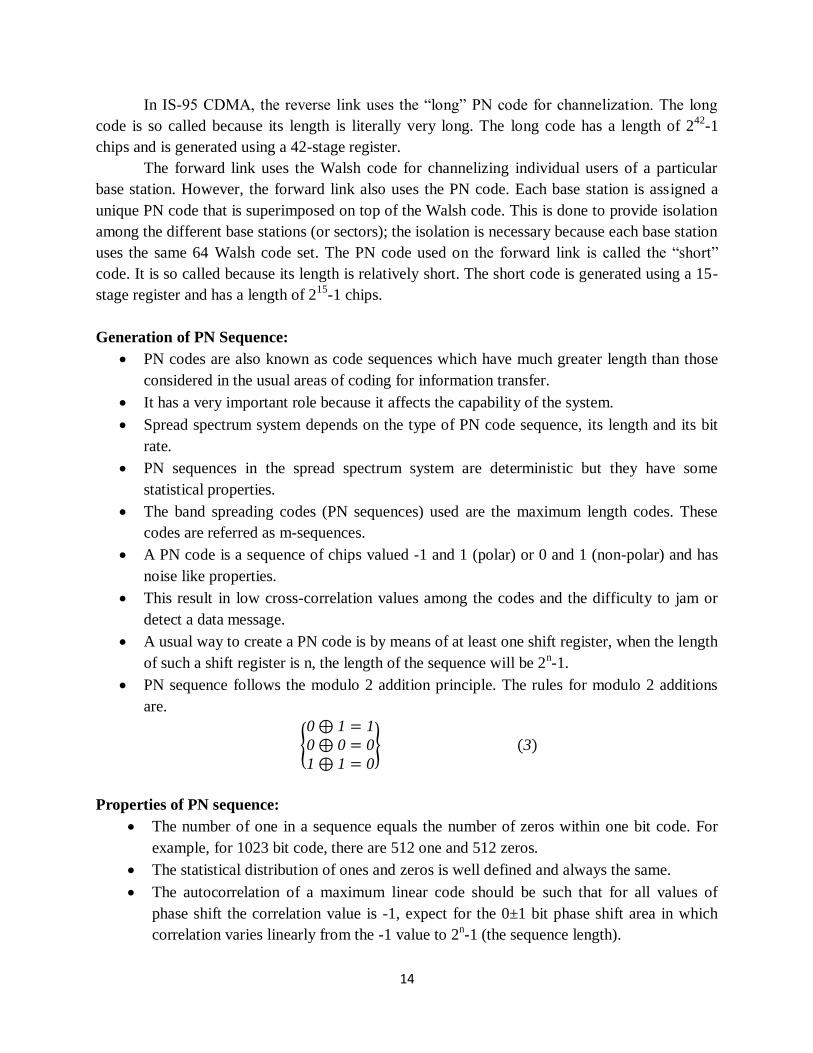
Fig. 4 shows the waveform achieved by DSSS system. In this example the PN code
generator is running at a higher clock frequency than that used for the data. When a logic high is
applied to the BPSK modulator the carrier undergoes, a phase change of 1800. When a logic low
applied to the BPSK modulator the carrier undergoes, a phase change of 00 phase change. The
carrier frequency containing the phase change information is received by the distant receiver.
This signal is then descrambled by a descrambler that relies on a PN code generator producing
PN code identical to the transmitter. The signal is then converted back into logic levels to
produce the original data.
In DSSS near-far effect is more dominating. This effect is present when an interfering
transmitter is much closer to the receiver than the intended transmitter. Although the cross
correlation between codes A and B is low, the correlation between the received signal from the
interfering transmitter and code A can be higher than the correlation between the received signal
from the intended transmitter and code A. the result is that proper data detection is not possible.
16
Fig. 4 DSSS system waveform
The basic block diagram of DSSS receiver is shown in Fig.5 .
In the receiver system the incoming RF signal is down converted to IF and then
multiplied by g1(t). the product is compared with the received IF signal in correlator. The
function of the correlator is to compare the two signals and recover the original data. The output
of correlator is applied to the conventional demodulator with such a wide bandwidth to
accommodate the dispreads signal. This process is completely time synchronized transmission
and it has no advantage over the cost because of the equipments shown in Fig. 5.

17
Fig. 5 Block diagram of DSSS receiver
FREQUENCY HOPPING SPREAD SPECTRUM SYSTEM:
In this method, Frequency Shift Key (FSK) frequency hopping system the total available
bandwidth is partitioned into smaller frequency bands and the total transmission time is
subdivided into smaller time slots. So the transmissions take place within a limited frequency
band for only a short period of time and then it switches to another frequency band and so on.
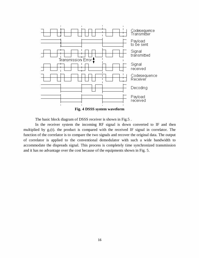
Fig. 6 indicates the way of transmission in FH systems.
In the above diagram, in first sequence frequency band f2 transmits in time shots t1, f4 in
time slot t2, f3 in time slot t3, f5 in t4, f1 in t5 and f2 in t6.
The combined pattern is called frequency hopping pattern and it is determined by a
binary code. Each station uses a different code sequence and such type of hopping pattern is
known as frequency time matrix. The generation of FH pattern is shown in Fig. 7.
18
Fig. 6 Frequency Time hopping matrix
Fig. 7 Block diagram of FHSS transmitter
Since the FSK is used in frequency hopping system, it is also called multiple frequency,
code related, Frequency Shift Keying. The code pattern generator consists of PN code generator
and a frequency synthesizer capable of responding to the coded outputs from the code generator.
The time interval in which the frequency is constant is known as frequency dwell time or hop
interval.

19
The FH spread spectrum receiver also uses the same correlation process to that used in
DHSS system. The block diagram of FH receiver is shown in Fig. 8.
Fig. 8 Block diagram of FHSS receiver
Here a local frequency synthesizer is switched with a synchronized replica of the
transmitted PN code and the resultant signal is multiplied to the received FHSS signal. This
multiplication removes the frequency hopes on the received signal and thus the original
modulated signal remains untouched. Then this signal is applied to the conventional demodulator
to get the orthogonal data/ information. This process gain is same as DSSS system.
A disadvantage of frequency hopping is to obtain high processing gain. So there is a need
of the frequency synthesizer able to perform fast hopping over the carrier frequencies. The faster
the hopping rate, the higher the processing gain. Frequency hopping is less effected by the near-
far effect.
RAKE RECEIVER
In CDMA spread spectrum systems, the chip rate is typically much greater than the flat
fading bandwidth of the channel. Whereas conventional modulation techniques require an
equalizer to undo the intersymbol interference between adjacent symbols, CDMA spreading
codes are designed to provide very low correlation between successive chips. Thus, propagation
delay spread in the radio channel merely provides multiple versions of the transmitted signal at
the receiver. If these multipath components are delayed in time by more than a chip duration,
they appear like uncorrelated noise at a CDMA receiver, and equalization is not required.
However, since there is useful information in the multipath components. CDMA
receivers may combine the time delayed versions of the original signal transmission in order to
improve the signal to noise ratio at the receiver. A RAKE receiver does just this — it attempts to
collect the time-shifted versions of the original signal by providing a separate correlation
receiver for each of the multipath signals.
The RAKE receiver, shown in Fig. 9, is essentially a diversity receiver designed
specifically for CDMA, where the diversity is provided by the fact that the multipath

20
components are practically uncorrelated from one another when their relative propagation delays
exceed a chip period.
Fig. 9 RAKE receiver
A RAKE receiver utilizes multiple correlators to separately detect the M strongest
multipath components. The outputs of each correlator are weighted to provide a better estimate
of the transmitted signal than is provided by a single component. Demodulation and bit decisions
are then based on the weighted outputs of the M correlators.
The basic idea of a RAKE receiver was first proposed by Price and Green. In outdoor
environments, the delay between multipath components is usually large and, if the chip rate is
properly selected, the low autocorrelation properties of a CDMA spreading sequence can assure
that multipath components will appear nearly uncorrelated with each
Assume M correlators are used in a CDMA receiver to capture the M strongest multipath
components. A weighting network is used to provide a linear combination of the correlator
output for bit detection. Correlator 1 is synchronized to the strongest multipath m1. Multipath
component m2 arrives τ1 later than component. The second correlator is synchronized to m2. It
correlates strongly with m2 but has low correlation with m1. Note that if only a single correlator
is used in the receiver, once the output of the single correlator is corrupted by fading, the receiver
cannot correct the value. Bit decisions based on only a single correlation may produce a large bit
error rate. In a RAKE receiver, if the output from one correlator is corrupted by fading, the
others may not be, and the corrupted signal may be discounted through the weighting process.
Decisions based on the combination of the M separate decision statistics offered by the RAKE
provide a form of diversity which can overcome fading and thereby improve CDMA reception.
The M decision statistics are weighted to form an overall decision statistic as shown in
Fig. 9. The outputs of the 1W correlators are denoted as Z1, Z2 ,... and ZM. They are weighted
by α1, α2,……, αM respectively. The weighting coefficients are based on the power or the SNR
from each correlator output. If the power or SNR is small out of a particular correlator, it will be
assigned a small weighting factor. Just as in the case of a maximal ratio combining diversity
scheme, the overall signal Z' is given by

21
𝑍 ′ = 𝛼 𝑚𝑍 𝑚 (11)
𝑀
𝑚=1
The weighting coefficients, am, are normalized to the output signal power of the
correlator in such a way that the coefficients sum to unity, as shown in equation (12).
𝛼 𝑚 = 𝑍 𝑚
2
𝑍 𝑚2𝑀
𝑚=1
(12)
As in the case of adaptive equalizers and diversity combining, there are many ways to
generate the weighting coefficients. However, due to multiple access interference, RAKE fingers
with strong multipath amplitudes will not necessarily provide strong output after correlation.
Choosing weighting coefficients based on the actual outputs of the correlators yields better
RAKE performance.
CODE DIVISION MULTIPLE ACCESS
In code division multiple access (CDMA) systems, the narrowband message signal is
multiplied by a very large bandwidth signal called the spreading signal. The spreading signal is a
pseudo-noise code sequence that has a chip rate which is orders of magnitudes greater than the
data rate of the message. All users in a CDMA system, as seen from Figure 8.5, use the same
carrier frequency and may transmit simultaneously. Each user has its own pseudorandom
codeword which is approximately orthogonal to all other codewords. The receiver performs a
time correlation operation to detect only the specific desired codeword. All other code- words
appear as noise due to decorrelation. For detection of the message signal, the receiver needs to
know the codeword used by the transmitter. Each user operates independently with rio
knowledge of the other users.
Basic CDMA transmitter
Let bk(t) bits for k users i.e.bits transmitted by users, Ck be sprading codes, J be spreading
factor. Sk(t) be transmitted signal and y(t) be received signal
In CDMA, the power of multiple users at a receiver determines the noise floor after
decorrelation. If the power of each user within a cell is not controlled such that they do not
appear equal at the base station receiver, then the near-far problem occurs.

22
Basic CDMA receiver
hk(t) is impulse response for user and n(t) is the noise.
The near-far problem occurs when many mobile users share the same channel. In general,
the strongest received mobile signal will capture the demodulator at a base station. In CDMA,
stronger received signal levels raise the noise floor at the base station demodulators for the
weaker signals, thereby decreasing the probability that weaker signals will be received. To
combat the near-far problem, power control is used in most CDMA implementations. Power
control is provided by each base station in a cellular system and assures that each mobile within
the base station coverage area provides the same signal level to the base station receiver. This
solves the problem of a nearby subscriber overpowering the base station receiver and drowning
out the signals of far away subscribers.Power control is implemented at the base station by
rapidly sampling the radio signal strength indicator (RSSI) levels of each mobile and then
sending a power change command over the forward radio link. Despite the use of power control
within each cell, out-of-cell mobiles provide interference which is not under the control of the
receiving base station. The features of CDMA including the following:
Many users of a CDMA system share the same frequency. Either TDD or FDD may be
used.
Unlike TDMA or FDMA, CDMA has a soft capacity limit. Increasing the number of
users in a CDMA system raises the noise floor in a linear manner.Thus, there is no
absolute limit on the number of users in CDMA. Rather,the system performance
gradually degrades for all users as the number of users is increased, and improves as the
number of users is decreased.
Multipath fading may be substantially reduced because the signal is spreadover a large
spectrum. If the spread spectrum bandwidth is greater than thecoherence bandwidth of
the channel, the inherent frequency diversity willmitigate the effects of small-scale
fading.
Channel data rates are very high in CDMA systems. Consequently, the symbol (chip)
duration is very short and usually much less than the channel delay spread. Since PN
sequences have low autocorrelation, multipath which is delayed by more than a chip will
1
( ) * ( ) ( )k
k k
k
y t h t S t n t

23
appear as noise. A RAKE receiver can beused to improve reception by collecting time
delayed versions of the required signal.
Since CDMA uses co-channel cells, it can use macroscopic spatial diversity to provide
soft handoff. Soft handoff is performed by the MSC, which can simultaneously monitor a
particular user from two or more base stations. The MSC may chose the best version of
the signal at any time without switching frequencies.
Self-jamming is a problem in CDMA system. Self-jamming arises from the fact that the
spreading sequences of different users are not exactly orthogonal, hence in the
despreading of a particular PN code, non-zero contributions to the receiver decision
statistic for a desired user arise from the transmissions of other users in the system.
The near-far problem occurs at a CDMA receiver if an undesired user has ahigh detected
power as compared to the desired user.
Simple System Capacity Comparison
It can be shown that, in a simple model scenario, CDMA is fundamentally inferior to
FDMA or TDMA in terms of capacity or spectral efficiency. For a practical very-small-terminal
scenario, however, the difference between CDMA and FDMA is not so great, especially where
performance is power limited owing to small antenna size and where thermal noise
predominates. As the total power in the system increases, the performance of CDMA becomes
inferior to that of FDMA as the former is limited by the self-jamming noise. This leads to a
graceful degradation of CDMA as the number of terminals in the network is increased.
CDMA does, however, offer a number of advantages when other effects are taken into
account, and particularly where interference from adjacent spot beams, or other systems, is a
factor. This is akin to the terrestrial cellular situation with adjacent cell interference. Such factors
can enhance CDMA performance to a level exceeding that which may be achieved by FDMA or
TDMA in those scenarios.
Because satellite downlink EIRP may be shared between transmissions on a pro rata
basis, and since other users contribute to the effective noise level, a CDMA system for speech
traffic can benefit directly from voice activation2,5. If the carrier can be removed during speech
pauses, the residual active channels can take advantage of the total EIRP at the same time as the

24
average aggregate self-interference-noise contribution is reduced. Hence, the overall network
capacity is optimised without the need for specific DSI techniques.
Note that in the satellite channel itself the CDMA transmission occupies a very wide
bandwidth and, consequently, the channel signal-to-noise ratio (SNR) may be very small (≪1).
The despreading process restores this to a decent value. The link C/N0 requirements, however,
which relate to the more relevant and fundamental noise spectral density, are unchanged to a first
order. Thus it cannot be said that either spread spectrum or CDMA fundamentally implies low
transmit power or a performance which is any different from FDMA etc., although it may be that
other practical benefits can arise.
A feature of CDMA is that the spread signals in the satellite transponder give rise to
noise-like IPs at low level and without peaks, having an effect smaller and more manageable
than that of narrowband IPs (as might arise with SCPC/FDMA). As a result, a transponder may
be operated closer to saturation than may an FDMA system, giving capacity benefits.
Conversely, a CDMA system is relatively immune to narrowband IPs or interference. Another
benefit of CDMA is resistance to multipath propagation, since once correlation lock has been
achieved other multipath signals will represent simply uncorrelated interference. This is of value
especially to mobile and VSAT systems. CDMA may additionally provide advantage where
polarisation diversity is employed, through rejection of crosspolar components.
CDMA offers a further practical benefit in that the frequency agility of an FDMA
transmitter/receiver is not required. In operation CDMA signals may be overlaid on the same
carrier frequency, partially overlapping, or given non-overlapping frequencies; it is also possible
to share a transponder with other signals on an FDMA basis.
The application of CDMA tends to be limited by the cost and complexity of the receiver,
together with the time taken to achieve synchronisation. In simple theory terms its performance
is inferior to that of FDMA or TDMA for a given power and bandwidth, but in practice the
performance can be superior to FDMA allowing for the latter's limitations of guard bands and
TWTA backoff. There is no need for network timing references as in TDMA, and speech duty
cycles may be readily exploited. CDMA is invariably used in conjunction with forward-error-
correcting (FEC) coding, and in practice may offer greater flexibility in this regard than either
FDMA or TDMA.
Some military satellite communications use CDMA as a multiple-access scheme. These
take advantage of the random-access nature of CDMA, where fixed or highly planned schemes
are impractical, and where downlink EIRP needs to be maximized for operation to small
terminals. (Although a degree of jamming and interference rejection is provided, other spread-
spectrum schemes with much greater processing gain and code security tend to be used for
specific antijam purposes.)
Spread-spectrum techniques (such as CDMA) became established in civil satellite
communications with the early equatorial VSAT system operating at C-band in the US. The
main reason for the adoption of CDMA in that system is understood to be the need for SS-
derived rejection of adjacent satellite interference experienced with the relatively wide antenna

25
beamwidths. It has also been suggested that the use of spread spectrum enabled operation within
the letter of FCC flux-density regulation limits. It appears that few if any Ku-band VSAT
systems currently employ CDMA, principally because the relatively narrow antenna beamwidths
at the shorter wavelengths reduce potential adjacent satellite interference.
As a topic, CDMA has been given a boost by its application in terrestrial cellular systems
(e.g. the US IS-95 scheme). A variant of this system is also employed in the Globalstar satellite
personal communication network of 48 satellites. In satellite systems there has been some work
under ESTEC sponsorship looking at synchronous CDMA for satellite communication
application; here all codes are time aligned, and by choice of orthogonal sets the selfjamming
noise may be reduced such schemes may, however, have certain difficulties and practical
limitations. There is also renewed interest generally in SS, including CDMA, for new satellite
services, as pressure on the radio spectrum increases, together with the density of traffic and
band sharing.
The overall merits or otherwise of CDMA are highly scenario dependent, and the subject
of considerable debate. In essence, it may be concluded that the main benefit to civil satellite
communication systems is the ability to operate in a predictable and equitable manner where
interference is likely, either from adjacent satellites (due to the wide antenna beamwidth) or from
other coband operations. An operator wishing to introduce its own system into an already
crowded environment might do well to use CDMA; it is not however a universal panacea, and if
all operators used it little would be gained.
CAPACITY OF CELLULAR CDMA
Channel capacity for a radio system can be defined as the maximum number of channels
or users that can be provided in a fixed frequency band. Radiocapacity is a parameter which
measures spectrum efficiency of a wireless system.
The capacity of CDMA systems is interference limited, while it is bandwidth limited in
FDMA and TDMA. Therefore, any reduction in the interference will cause a linear increase in
the capacity of CDMA. Put another way, in a CDMA system, the link performance for each user
increases as the number of users decreases.
A straightforward way to reduce interference is to use multisectorized antennas, which
results in spatial isolation of users. The directional antennas receive signals from only a fraction
of the current users, thus leading to the reduction of interference.
Another way of increasing CDMA capacity is to operate in a discontinuous transmission
mode (DTX), where advantage is taken of the intermittent nature of speech. In DTX, the
transmitter is turned off during the periods of silence in speech. It has been observed that voice
signals have a duty factor of about 3/8 in landline networks and 1/2 for mobile systems, where
background noise and vibration can trigger voice activity detectors. Thus, the average capacity of
a CDMA system can be increased by a factor inversely proportional to the duty factor.
For evaluating the capacity of CDMA system, first consider a single cell system. The
cellular network consists of a large number of mobile users communicating with a base station

26
Let the number of users be N. Then, each demodulator at the cell site receives a
composite waveform containing the desired signal of power S and (N - I) interfering users, each
of which has power, S. Thus, the signal-to-noise ratio is
1
1 1
SSNR
N S N
……………………….. (1)
In addition to SNR, bit energy-to-noise ratio is an important parameter in communication
systems. It is obtained by dividing the signal power by the base band information bit rate, R, and
the interference power by the total RF band width, W. The SNR at the base station receiver can
be represented in terms of 0
bE
N given by
0 1 1
bE S R W R
N N S W N
……………………….. (2)
Equation does not take into account the background thermal noise, in the spread bandwidth . To
take this noise into consideration, 0
bE
N can be represented as
0 1
bE W R
N N S
The number of users that can access the system is thus given as 0
1b
W RN S
E N
where W R is called the processing gain. The background noise determines the cell radius for a
given transmitter power.
In order to achieve an increase in capacity, the interference due to other users should be
reduced. This can be done by decreasing the denominator of equations (1) or (2).
The first technique for reducing interference is anterma sectorization. As an example, a
cell site with three antennas, each having a beam width of 1200, has interference N0' which is
one-third of the interference received by an onini-directional antenna. This increases the capacity
by a factor of 3 since three times as many users may now be served within a sector while
matching the performance of the omni-directional antenna system. The same number of users in
an omni-directional cell may now be served in 1/3rd the area. The second technique involves the
monitoring of voice activity such that each transmitter is switched off during periods of no voice
activity. Voice activity is denoted by a factor , and the interference term becomes 1sN ,
where Ns is the number of users per sector. With the use of these two techniques, the new
average value of 0
bE
N within a sector is given as
0 1
b
s
E W R
N N S
When the number of users is large and the system is interference limited rather than noise
limited, the number of users can be shown to be
0
11s
b
W RN
E
N
If the voice activity factor is assumed to hate a value of 3/8, and three sectors per cell site
are used, the above equation demonstrates that the SNR increases by a factor of 8, which leads to

27
an 8 fold increase in the number of users compared to an omni-directional antenna system with
no voice activity detection.
Applications of spread spectrum
1. Wireless local area network (WLAN)
A WLAN is a flexible data communication system implemented as an extension to or an
alternative for a wired local area network. WLANs transmit and receive data over the air,
minimizing the need for wired connections. Thus, WLANs combine data connectivity with user
mobility and enable movable LANs.
Most WLAN systems use spread spectrum technique (both frequency hopping and direct
sequence). WLANs are being used in health care, retail, manufacturing, warehousing, academic
and other arenas. These industries have profited from the productivity gains of using handheld
terminals and notebook computers to transmit real-time information to centralised hosts for
processing. WLANs offer productivity, convenience and cost advantages over wired networks.
2. Space systems
In space stations, which are continuously accessible to interference, spread-spectrum
methods have proved effective. This is especially true for communication satellites. In general,
satellites do not employ processing on-board as it adds to the complexity and would limit the
number of satellite users.
A simple repeating satellite is used, so all the spread spectrum modulation and
demodulation must be done on the ground. With no on-board processing, the satellite is forced to
transmit an uplink interference signal, which reduces the spacecraft transmitter power to send the
desired signal. Another disadvantage of no on-board processing is that every receiver would have
to acquire a spread-spectrum demodulator.
3. Global positioning system (GPS)
GPS is a satellite-based navigation system developed and operated by the US Department
of Defense. The idea behind GPS is to transmit spread-spectrum signals that allow range
measurement from an unknown satellite location. With knowledge of the transmitter location and
the distance to the satellite, the receiver can locate itself on a sphere whose radius is the distance
measured. After receiving signals and making range measurement on other satellites, the receiver
can calculate its position based on the intersection of several spheres.
GPS permits users to determine their 3-D position, velocity and time. This service is
available for military and commercial users round the clock, in all weather, anywhere in the

28
world. GPS uses NAVSTAR (NAVigation Satellite Timing And Ranging) satellites. The
constellation consists of 21 operational satellites and three active spares.
This provides a GPS receiver with four to twelve usable satellites ‗in view‘ at any time. A
minimum of four satellites allow the GPS card to compute latitude, longitude, altitude and GPS
system time. The NAVSTAR satellites orbit the earth at an altitude of 10,898 Nautical miles in
six 55-degree orbital planes, with four satellites in each plane. The orbital period of each satellite
is approximately 12 hours. The GPS satellite signal contains information to identify the satellite,
as also positioning, timing, ranging data and satellite status.
The satellites are identified by the space vehicle number or the pseudo-random code
number. They transmit on two L-band frequencies: 1.57542 GHz (L1) and 1.22760 GHz (L2).
The L1 signal has a sequence encoded on the carrier frequency by a modulation technique that
contains two codes, a precision (P) code and a course/acquisition (C/A) code. The L2 code
contains only P code, which is encrypted for military and authorised commercial users.
4. Personal communications
Spread-spectrum signals can be overlaid onto bands where other systems are already
operating, with minimal performance impact to or from the other systems.
The anti-interference characteristics of spread-spectrum signals are important in
environments where signal interference can be harsh, such as networks operating on
manufacturing floors.
Cellular systems designed with code-division multiple-access (CDMA) spread-spectrum
technology offer greater operational flexibility and possibly a greater overall system
capacity than systems built on frequency-division multiple-access (FDMA) or
timedivision multiple-access (TDMA) methods.
The anti-mutipath characteristics of spread-spectrum signaling and reception techniques
are desirable in applications where multipath is likely to be prevalent. For these reasons,
many companies have begun developing spread-spectrum systems.

29
Applications of CDMA technology
CDMA technology is used in commercial cellular communications to make better use of radio
spectrum when compare to other technologies. This technology was used as a military technology
for first time in the World War II by the English associates to break the German attempts of
jamming transmissions.
CDMA technology is known as a spread-spectrum technique which allows many users to occupy
the same time and frequency allocations in a given band and space. Individual conversations are
encoded with the help of pseudo-random digital sequence.
CDMA has been to be immensely useful not only for voice calls but also for data transmission.
CDMA based data exchange services have been catering not only to mobile phones but are also
being used in internet support devices.
For businesses, CDMA aids in providing high speed push to talk and push to email services. Push
to talk gives the mobile an ability to be used as a walky-talky device while push to mail allows
one to have email facility every time. Read more email and working of email. These services are
often exempted from the service charges by the operator,.
Also, video conferencing feature allows business representatives from all over the world to
communicate altogether without any hassles. For Consumers, plenty of services are there
depending on their connection speed. It covers the basic text messaging service and multimedia
messaging service.
Also, for medium and high speed connections various services such as monetary transactions,
internet surfing, multimedia, gaming, social networking, video calls are available at quite
affordable prices under CDMA.
CDMA is openly regarded as the highway mode of wireless communications and has been
responsible for giving fast and safe modes of data exchange such as 3G and recently it has been
merged with GSM to give high speed 4G or LTE internet services. Highly digital, CDMA stands
as a power efficient and hence an economic data exchange mode which can connect almost every
part of the world without posing risk to the detain terms of secrecy and losses.
Due to inherent advantages of CDMA over TDMA and FDMA such as user capacity, soft hand
offs and security, etc., CDMA emerges as a winner in the battle of wireless technology and
services. CDMA allows far greater development and the use of broad band devices such as
wireless laptop modems, GPS system units and other innovative devices.
For business purpose, CDMA supports in providing high speed push to talk and push to email
services. Push to talk gives mobile an ability to be used as a walky-talky device. These services
are exempted from the service charges imposed by the operators making CDMA cost effective.
CDMA is considered as the highest mode of wireless communications, and is responsible for
gibing fast and safe mode of data exchange such as 3G. Recently, CDMA has merged with
the GSM technology to give a high-speed 4G or LTE internet services.