Unit II: DC Circuit Analysis (12 hrs)
19
Unit II: DC Circuit Analysis (12 hrs) 2.1 Circuits concepts (Lumped and distributed parameters) 2.2 Linear and non- linear parameter, passive and active circuits 2.3 Circuit elements (Resistance, Capacitance and Inductance), their properties and characteristics in a geometrical and hardware aspects, color coding 2.4 Series of parallel compilation of resistance, equivalent resistance and its calculation 2.5 Star-delta transformation 2.6 Concept of power, energy and its calculations 2.7 Short and open circuit 2.8 Ideal and non-ideal sources, source conversion 2.9 Voltage divider and current divider formula 2.10 Kirchhoff’s current and voltage laws 2.11 Nodal Method and Mesh method of network analysis (without dependent source) 2.12 Network theorems (i.e. Superposition Thevenin’s, Norton’s), Maximum power transfer. 2.1 Circuits concepts (Lumped and distributed parameters): Lumped parameters Physically separate elements are termed as lumped parameters. Concept of circuit theory or network theory is based on lumped elements. Lumped systems are those systems in which electrical properties like R, L, C etc are assumed to be located on small space of the circuit. These systems are applicable for low frequency application. When the voltage across and current through the element don’t vary with dimension of the element, it is called lumped circuit elements. Examples: Resistor connected in any electrical circuit In lumped parameters elements i.e. electrical parameters (Resistance (R), Inductance (L) and Capacitance(C) ) are assumed to concentrated at one place. Example resistor connected in any circuit. Lumped-parameters circuits consist of discrete circuit components connected by, what are assumed to be, perfect conductors. An underlying assumption of lumped parameters circuits is that the perfect conductors instantaneously transfer current with no voltage drop. The lumped-parameters circuit model is inappropriate if the distances involved are large or the voltages and currents are changing very rapidly. In these cases, distributed-parameters models must be used. These models are considerably more mathematically complex than lumped-parameters models.
Transcript of Unit II: DC Circuit Analysis (12 hrs)

Unit II: DC Circuit Analysis (12 hrs)
2.1 Circuits concepts (Lumped and distributed parameters)
2.2 Linear and non- linear parameter, passive and active circuits
2.3 Circuit elements (Resistance, Capacitance and Inductance), their properties and
characteristics in a geometrical and hardware aspects, color coding
2.4 Series of parallel compilation of resistance, equivalent resistance and its calculation
2.5 Star-delta transformation
2.6 Concept of power, energy and its calculations
2.7 Short and open circuit
2.8 Ideal and non-ideal sources, source conversion
2.9 Voltage divider and current divider formula
2.10 Kirchhoff’s current and voltage laws
2.11 Nodal Method and Mesh method of network analysis (without dependent source)
2.12 Network theorems (i.e. Superposition Thevenin’s, Norton’s), Maximum power transfer.
2.1 Circuits concepts (Lumped and distributed parameters):
Lumped parameters
Physically separate elements are termed as lumped parameters.
Concept of circuit theory or network theory is based on lumped elements.
Lumped systems are those systems in which electrical properties like R, L, C etc are assumed
to be located on small space of the circuit. These systems are applicable for low frequency
application.
When the voltage across and current through the element don’t vary with dimension of the
element, it is called lumped circuit elements. Examples: Resistor connected in any electrical
circuit
In lumped parameters elements i.e. electrical parameters (Resistance (R), Inductance (L) and
Capacitance(C) ) are assumed to concentrated at one place. Example resistor connected in
any circuit.
Lumped-parameters circuits consist of discrete circuit components connected by, what are
assumed to be, perfect conductors. An underlying assumption of lumped parameters circuits
is that the perfect conductors instantaneously transfer current with no voltage drop.
The lumped-parameters circuit model is inappropriate if the distances involved are large or
the voltages and currents are changing very rapidly. In these cases, distributed-parameters
models must be used. These models are considerably more mathematically complex than
lumped-parameters models.
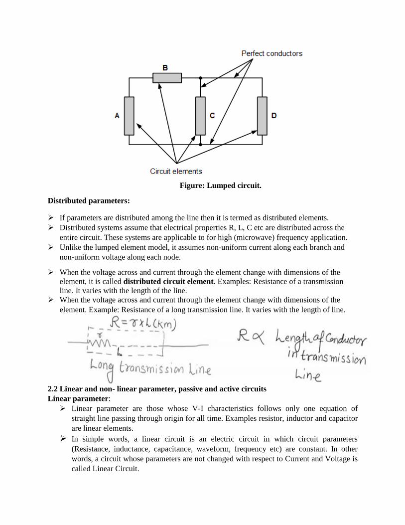
Figure: Lumped circuit.
Distributed parameters:
If parameters are distributed among the line then it is termed as distributed elements.
Distributed systems assume that electrical properties R, L, C etc are distributed across the
entire circuit. These systems are applicable to for high (microwave) frequency application.
Unlike the lumped element model, it assumes non-uniform current along each branch and
non-uniform voltage along each node.
When the voltage across and current through the element change with dimensions of the
element, it is called distributed circuit element. Examples: Resistance of a transmission
line. It varies with the length of the line.
When the voltage across and current through the element change with dimensions of the
element. Example: Resistance of a long transmission line. It varies with the length of line.
2.2 Linear and non- linear parameter, passive and active circuits
Linear parameter:
Linear parameter are those whose V-I characteristics follows only one equation of
straight line passing through origin for all time. Examples resistor, inductor and capacitor
are linear elements.
In simple words, a linear circuit is an electric circuit in which circuit parameters
(Resistance, inductance, capacitance, waveform, frequency etc) are constant. In other
words, a circuit whose parameters are not changed with respect to Current and Voltage is
called Linear Circuit.
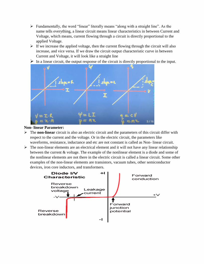
Fundamentally, the word “linear” literally means “along with a straight line”. As the
name tells everything, a linear circuit means linear characteristics in between Current and
Voltage, which means, current flowing through a circuit is directly proportional to the
applied Voltage.
If we increase the applied voltage, then the current flowing through the circuit will also
increase, and vice versa. If we draw the circuit output characteristic curve in between
Current and Voltage, it will look like a straight line
In a linear circuit, the output response of the circuit is directly proportional to the input.
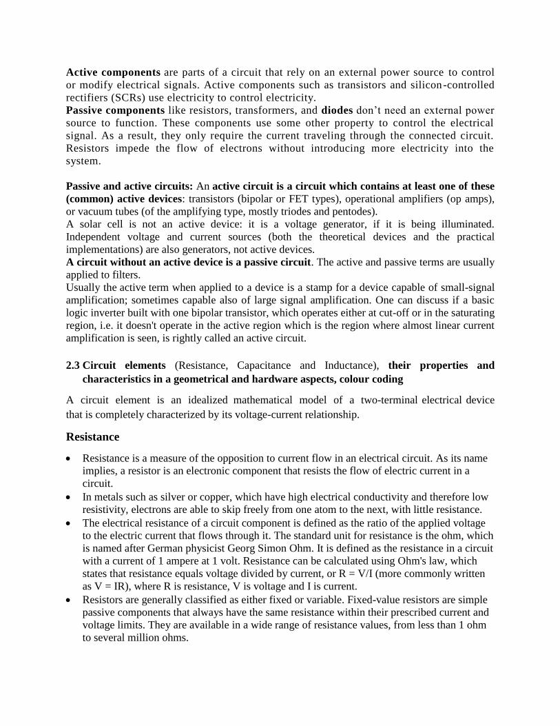
Non- linear Parameter:
The non-linear circuit is also an electric circuit and the parameters of this circuit differ with
respect to the current and the voltage. Or in the electric circuit, the parameters like
waveforms, resistance, inductance and etc are not constant is called as Non- linear circuit.
The non-linear elements are an electrical element and it will not have any linear relationship
between the current & voltage. The example of the nonlinear element is a diode and some of
the nonlinear elements are not there in the electric circuit is called a linear circuit. Some other
examples of the non-linear elements are transistors, vacuum tubes, other semiconductor
devices, iron core inductors, and transformers.
Active components are parts of a circuit that rely on an external power source to control
or modify electrical signals. Active components such as transistors and silicon-controlled
rectifiers (SCRs) use electricity to control electricity.
Passive components like resistors, transformers, and diodes don’t need an external power
source to function. These components use some other property to control the electrical
signal. As a result, they only require the current traveling through the connected circuit.
Resistors impede the flow of electrons without introducing more electricity into the
system.
Passive and active circuits: An active circuit is a circuit which contains at least one of these
(common) active devices: transistors (bipolar or FET types), operational amplifiers (op amps),
or vacuum tubes (of the amplifying type, mostly triodes and pentodes).
A solar cell is not an active device: it is a voltage generator, if it is being illuminated.
Independent voltage and current sources (both the theoretical devices and the practical
implementations) are also generators, not active devices.
A circuit without an active device is a passive circuit. The active and passive terms are usually
applied to filters.
Usually the active term when applied to a device is a stamp for a device capable of small-signal
amplification; sometimes capable also of large signal amplification. One can discuss if a basic
logic inverter built with one bipolar transistor, which operates either at cut-off or in the saturating
region, i.e. it doesn't operate in the active region which is the region where almost linear current
amplification is seen, is rightly called an active circuit.
2.3 Circuit elements (Resistance, Capacitance and Inductance), their properties and
characteristics in a geometrical and hardware aspects, colour coding
A circuit element is an idealized mathematical model of a two-terminal electrical device
that is completely characterized by its voltage-current relationship.
Resistance
Resistance is a measure of the opposition to current flow in an electrical circuit. As its name
implies, a resistor is an electronic component that resists the flow of electric current in a
circuit.
In metals such as silver or copper, which have high electrical conductivity and therefore low
resistivity, electrons are able to skip freely from one atom to the next, with little resistance.
The electrical resistance of a circuit component is defined as the ratio of the applied voltage
to the electric current that flows through it. The standard unit for resistance is the ohm, which
is named after German physicist Georg Simon Ohm. It is defined as the resistance in a circuit
with a current of 1 ampere at 1 volt. Resistance can be calculated using Ohm's law, which
states that resistance equals voltage divided by current, or R = V/I (more commonly written
as V = IR), where R is resistance, V is voltage and I is current.
Resistors are generally classified as either fixed or variable. Fixed-value resistors are simple
passive components that always have the same resistance within their prescribed current and
voltage limits. They are available in a wide range of resistance values, from less than 1 ohm
to several million ohms.
Variable resistors are simple electromechanical devices, such as volume controls and dimmer
switches, which change the effective length or effective temperature of a resistor when you
turn a knob or move a slide control. An example of an inductor made from a copper wire
installed on a circuit board.
The following are the main laws of resistance: (i) Resistance of a conductor is directly proportional to its length, provided temperature and
other physical conditions remain unchanged.
It means that R ∝ L i.e., if the length increases, the resistance also increases and if length
decreases, its resistance also decreases.
(ii) Resistance of a conductor is inversely proportional to its area of cross section, other
conditions remaining the same.
If A is the area of cross section, then:
R α 1/A
Or R α 1/πr2
where r is radius of the wire
Keeping the length same, if the radius of the wire is doubled then :
R α 1(2r)2 α 1/4r
2
Or R α ¼.1/πr2, or R becomes one fourth.
Similarly if r is made half, then :
R α 1/(r/2)2
α 4/r2 α 4(1/r
2), or R becomes 4 times
This shows that R is α 1/A
(iii) R depends on the nature of the material of the conductor. It means, if we take equal
lengths of wires of copper, aluminium and iron and all of the same cross-sectional area, their
resistance are different from each other since they are of different materials.
Inductance
Inductors resist or oppose changes of current but will easily pass a steady state DC current.
This ability of an inductor to resist changes in current and which also relates current, i with
its magnetic flux linkage, NΦ as a constant of proportionality is called Inductance which is
given the symbol L with units of Henry, (H) after Joseph Henry. One Henry is the amount of
inductance that is required to induce 1 volt of electromotive force (the electrical pressure
from an energy source) when the current is changing at 1 ampere per second.
An inductor is an electronic component consisting of a coil of wire with an electric current
running through it, creating a magnetic field.
One important application of inductors in active circuits is that they tend to block high-
frequency signals while letting lower-frequency oscillations pass. Note that this is the
opposite function of capacitors. Combining the two components in a circuit can selectively
filter or generate oscillations of almost any desired frequency.
Self-inductance is the phenomenon in which emf is induced in a coil due to the change of
current through the coil itself. Self-inductance of the coil depends on the area of cross-
section of the coil, the number of turns per unit length in the coil, the length of the solenoid
and the permeability of the core material.
Factors Affecting Inductance
There are four basic factors of inductor construction determining the amount of inductance
created. These factors all dictate inductance by affecting how much magnetic field flux will
develop for a given amount of magnetic field force (current through the inductor’s wire coil):
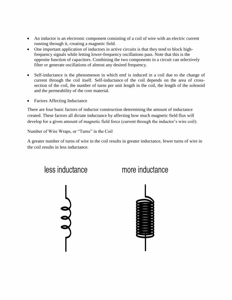
Number of Wire Wraps, or “Turns” in the Coil
A greater number of turns of wire in the coil results in greater inductance, fewer turns of wire in
the coil results in less inductance.
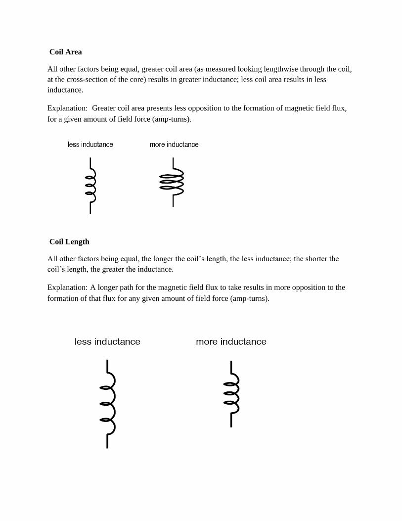
Coil Area
All other factors being equal, greater coil area (as measured looking lengthwise through the coil,
at the cross-section of the core) results in greater inductance; less coil area results in less
inductance.
Explanation: Greater coil area presents less opposition to the formation of magnetic field flux,
for a given amount of field force (amp-turns).
Coil Length
All other factors being equal, the longer the coil’s length, the less inductance; the shorter the
coil’s length, the greater the inductance.
Explanation: A longer path for the magnetic field flux to take results in more opposition to the
formation of that flux for any given amount of field force (amp-turns).
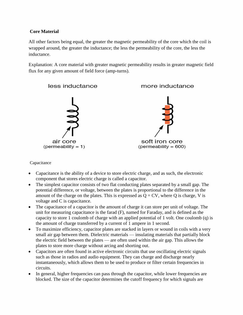
Core Material
All other factors being equal, the greater the magnetic permeability of the core which the coil is
wrapped around, the greater the inductance; the less the permeability of the core, the less the
inductance.
Explanation: A core material with greater magnetic permeability results in greater magnetic field
flux for any given amount of field force (amp-turns).
Capacitance
Capacitance is the ability of a device to store electric charge, and as such, the electronic
component that stores electric charge is called a capacitor.
The simplest capacitor consists of two flat conducting plates separated by a small gap. The
potential difference, or voltage, between the plates is proportional to the difference in the
amount of the charge on the plates. This is expressed as Q = CV, where Q is charge, V is
voltage and C is capacitance.
The capacitance of a capacitor is the amount of charge it can store per unit of voltage. The
unit for measuring capacitance is the farad (F), named for Faraday, and is defined as the
capacity to store 1 coulomb of charge with an applied potential of 1 volt. One coulomb (q) is
the amount of charge transferred by a current of 1 ampere in 1 second.
To maximize efficiency, capacitor plates are stacked in layers or wound in coils with a very
small air gap between them. Dielectric materials — insulating materials that partially block
the electric field between the plates — are often used within the air gap. This allows the
plates to store more charge without arcing and shorting out.
Capacitors are often found in active electronic circuits that use oscillating electric signals
such as those in radios and audio equipment. They can charge and discharge nearly
instantaneously, which allows them to be used to produce or filter certain frequencies in
circuits.
In general, higher frequencies can pass through the capacitor, while lower frequencies are
blocked. The size of the capacitor determines the cutoff frequency for which signals are
blocked or allowed to pass. Capacitors in combination can be used to filter selected
frequencies within a specified range.
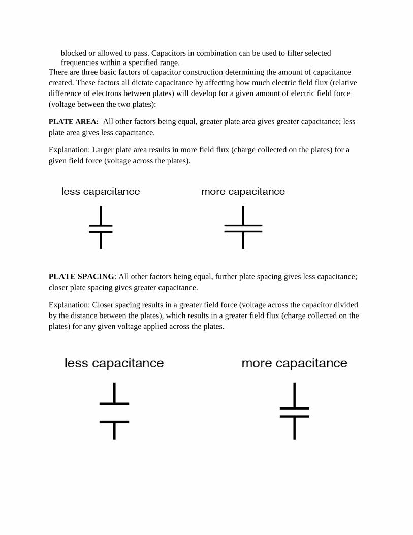
There are three basic factors of capacitor construction determining the amount of capacitance
created. These factors all dictate capacitance by affecting how much electric field flux (relative
difference of electrons between plates) will develop for a given amount of electric field force
(voltage between the two plates):
PLATE AREA: All other factors being equal, greater plate area gives greater capacitance; less
plate area gives less capacitance.
Explanation: Larger plate area results in more field flux (charge collected on the plates) for a
given field force (voltage across the plates).
PLATE SPACING: All other factors being equal, further plate spacing gives less capacitance;
closer plate spacing gives greater capacitance.
Explanation: Closer spacing results in a greater field force (voltage across the capacitor divided
by the distance between the plates), which results in a greater field flux (charge collected on the
plates) for any given voltage applied across the plates.
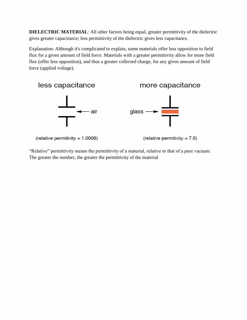
DIELECTRIC MATERIAL: All other factors being equal, greater permittivity of the dielectric
gives greater capacitance; less permittivity of the dielectric gives less capacitance.
Explanation: Although it's complicated to explain, some materials offer less opposition to field
flux for a given amount of field force. Materials with a greater permittivity allow for more field
flux (offer less opposition), and thus a greater collected charge, for any given amount of field
force (applied voltage).
“Relative” permittivity means the permittivity of a material, relative to that of a pure vacuum.
The greater the number, the greater the permittivity of the material

Resistor Color Coding uses colored bands to quickly identify a resistors resistive value and its
percentage of tolerance with the physical size of the resistor indicating its wattage rating.
Generally, the resistance value, tolerance, and wattage rating are printed on the body of a resistor
as numbers or letters when the resistors body is big enough to read the print, such as large power
resistors.
Color Digit Multiplier Tolerance (%)
Black 0 100(1)
Brown 1 101 1
Red 2 102 2
Orange 3 103
Yellow 4 104
Green 5 105 0.5
Blue 6 106 0.25
Violet 7 107 0.1
Grey 8 108
White 9 109
Gold 10-1
5
Silver 10-2
10
(none) 20
The colors brown, red, green, blue, and violet are used as tolerance codes on 5-band resistors
only. All 5-band resistors use a colored tolerance band.
The blank (20%) “band” is only used with the “4-band” code (3 colored bands + a blank “band”).
Yellow-Violet-Orange-Gold Color Code
A resistor colored Yellow-Violet-Orange-Gold would be 47 kΩ with a tolerance of +/- 5%.
Green-Red-Gold-Silver Color Code
A resistor colored Green-Red-Gold-Silver would be 5.2 Ω with a tolerance of +/- 10%.
White-Violet-Black Color Code
A resistor colored White-Violet-Black would be 97 Ω with a tolerance of +/- 20%. When you see
only three color bands on a resistor, you know that it is actually a 4-band code with a blank
(20%) tolerance band.
Orange-Orange-Black-Brown-Violet Color Code
A resistor colored Orange-Orange-Black-Brown-Violet would be 3.3 kΩ with a tolerance of +/-
0.1%.
Brown-Green-Grey-Silver-Red Color Code
A resistor colored Brown-Green-Grey-Silver-Red would be 1.58 Ω with a tolerance of +/- 2%.
Blue-Brown-Green-Silver-Blue Color Code
A resistor colored Blue-Brown-Green-Silver-Blue would be 6.15 Ω with a tolerance of +/-
0.25%.
2.13 Series of parallel compilation of resistance, equivalent resistance and its
calculation
Resistors in Series and in Parallel
Resistors are probably the most commonly occurring components in electronic circuits. Practical
circuits often contain very complicated combinations of resistors. It is, therefore, useful to have a
set of rules for finding the equivalent resistance of some general arrangement of resistors. It turns
out that we can always find the equivalent resistance by repeated application of two simple rules.
These rules relate to resistors connected in series and in parallel.
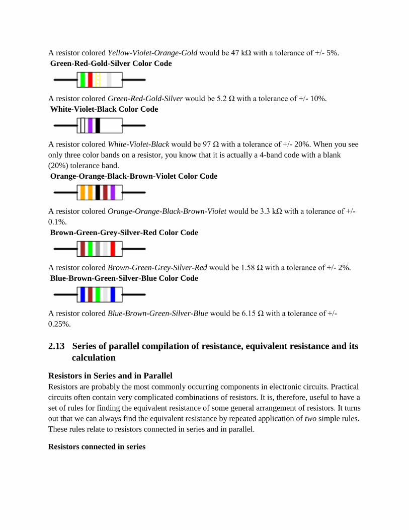
Resistors connected in series
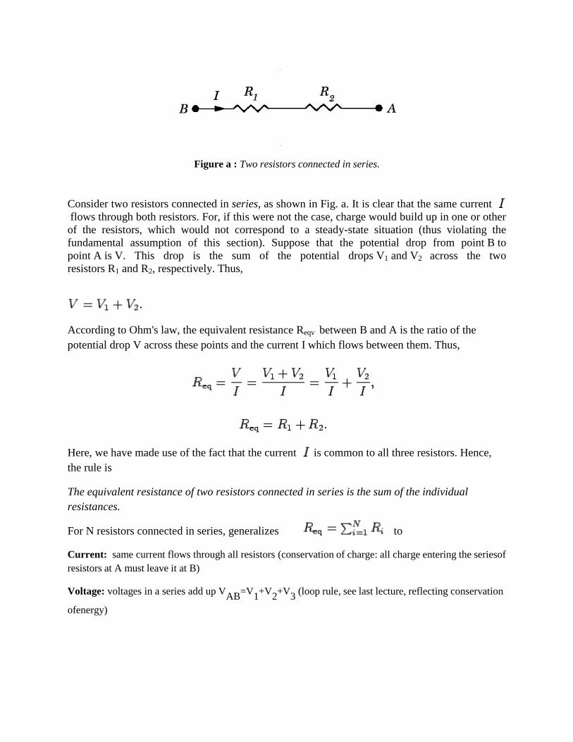
Figure a : Two resistors connected in series.
Consider two resistors connected in series, as shown in Fig. a. It is clear that the same current
flows through both resistors. For, if this were not the case, charge would build up in one or other
of the resistors, which would not correspond to a steady-state situation (thus violating the
fundamental assumption of this section). Suppose that the potential drop from point B to
point A is V. This drop is the sum of the potential drops V1 and V2 across the two
resistors R1 and R2, respectively. Thus,
According to Ohm's law, the equivalent resistance Reqv between B and A is the ratio of the
potential drop V across these points and the current I which flows between them. Thus,
Here, we have made use of the fact that the current is common to all three resistors. Hence,
the rule is
The equivalent resistance of two resistors connected in series is the sum of the individual
resistances.
For N resistors connected in series, generalizes to
Current: same current flows through all resistors (conservation of charge: all charge entering the series of
resistors at A must leave it at B)
Voltage: voltages in a series add up VAB
=V1+V
2+V
3 (loop rule, see last lecture, reflecting conservation
of energy)
Resistors connected in Parallel:
Figure b: Two resistors connected in parallel.
Consider two resistors connected in parallel, as shown in Fig. b. It is clear, from the figure, that
the potential drop across the two resistors is the same. In general, however, the
currents I1 and I2 which flow through resistors R1 and R2, respectively, are different. According
to Ohm's law, the equivalent resistance Reqv between B and A is the ratio of the potential
drop V across these points and the current I which flows between them. This current must equal
the sum of the currents I1 and I2 flowing through the two resistors; otherwise charge would build
up at one or both of the junctions in the circuit. Thus,
It follows that
Giving
Here, we have made use of the fact that the potential drop V is common to all three resistors.
Clearly, the rule is
The reciprocal of the equivalent resistance of two resistances connected in parallel is the sum of
the reciprocals of the individual resistances.
For resistors connected in parallel, Equation generalizes to.
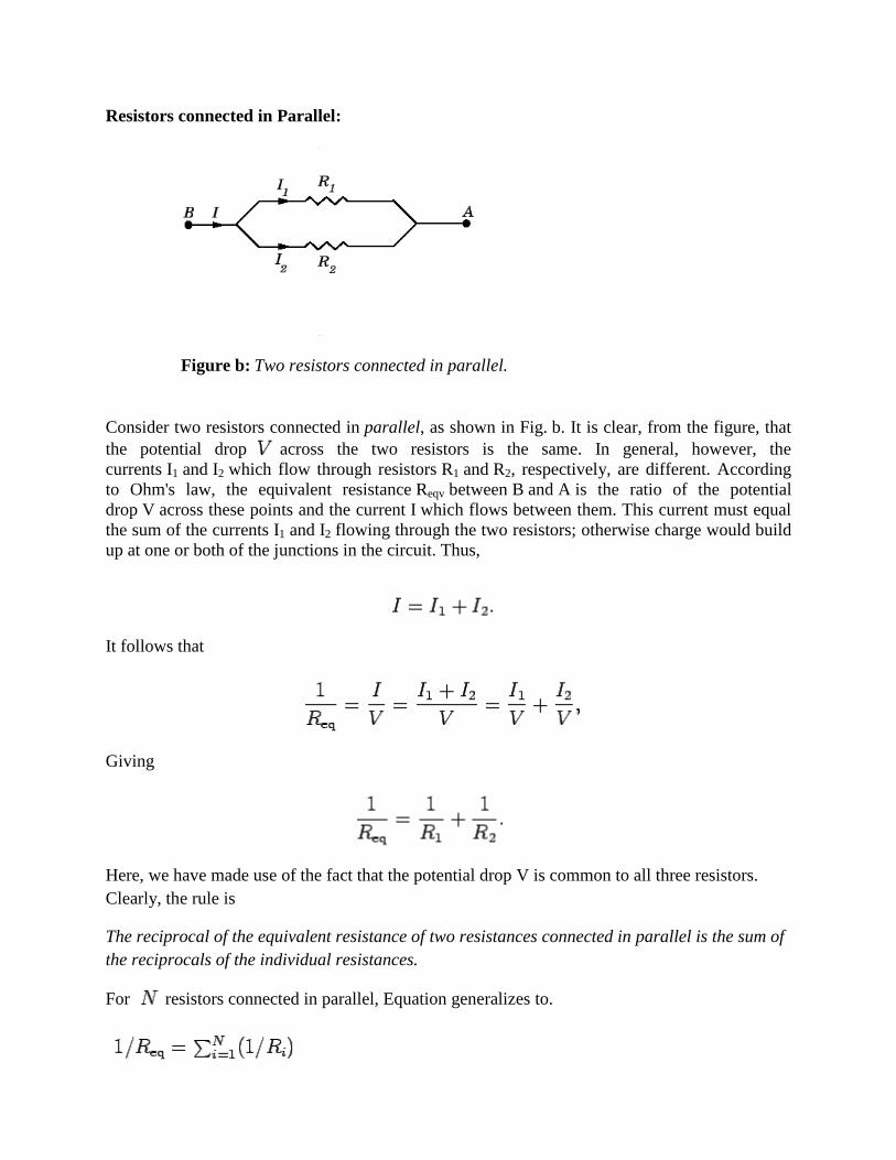
From the above discussion for a series and parallel circuit we conclude that
S.N Series circuit Parallel circuit
1. Same current flows through all parts of circuit Same voltage acts across all parts of the circuit
2. Applied voltage is equal to the sum of voltage
drops across the different parts of the circuit.
Different resistors (or branches) have their individual
currents.
3. Different resistors have their individual voltage
drops.
Total circuit current is equal to the sum of individual
currents through the various resistors (or branches).
4. Voltage drop across individual resistor is directly
proportional to its resistance, current being the
same in each resistor.
Branch currents are additive.
5. Voltage drops are additive. Conductances are additive
6. Resistances are additive. The reciprocal of the equivalent or combined resistance
is equal to the sum of the reciprocals of the resistances of
the individual branches.
7. Powers are additive. Powers are additive
For example, in the following circuit calculate the total current ( IT ) taken from the 12v supply.
Resistors in Series and Parallel Example No2
Find the equivalent resistance, REQ for the following resistor combination circuit.

We can find the equivalent resistance of the R8 to R10 combination and call it RA.
RA is in series with R7 therefore the total resistance will be RA + R7 = 4 + 8 = 12Ω as shown.
This resistive value of 12Ω is now in parallel with R6 and can be calculated as RB.
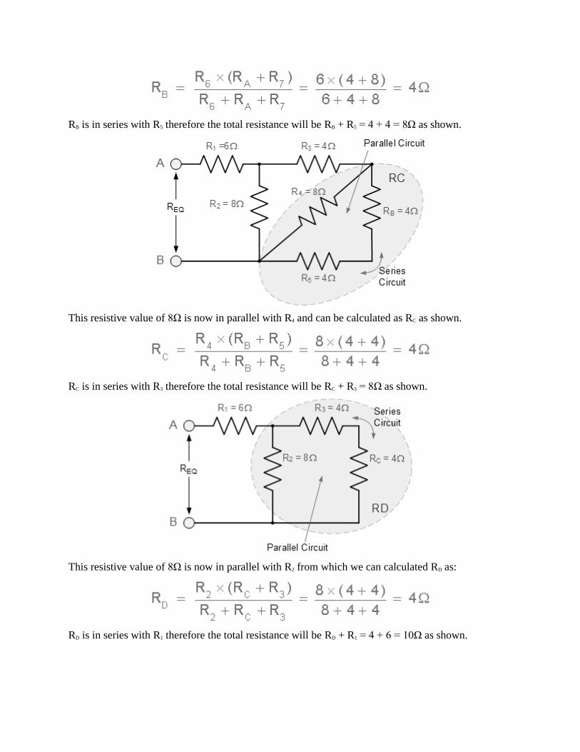
RB is in series with R5 therefore the total resistance will be RB + R5 = 4 + 4 = 8Ω as shown.
This resistive value of 8Ω is now in parallel with R4 and can be calculated as RC as shown.
RC is in series with R3 therefore the total resistance will be RC + R3 = 8Ω as shown.
This resistive value of 8Ω is now in parallel with R2 from which we can calculated RD as:
RD is in series with R1 therefore the total resistance will be RD + R1 = 4 + 6 = 10Ω as shown.
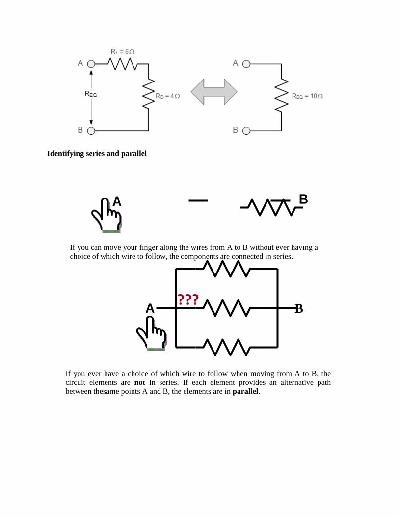
Identifying series and parallel
If you can move your finger along the wires from A to B without ever having a
choice of which wire to follow, the components are connected in series.
B
If you ever have a choice of which wire to follow when moving from A to B, the
circuit elements are not in series. If each element provides an alternative path between the same points A and B, the elements are in parallel.
A B
A ???
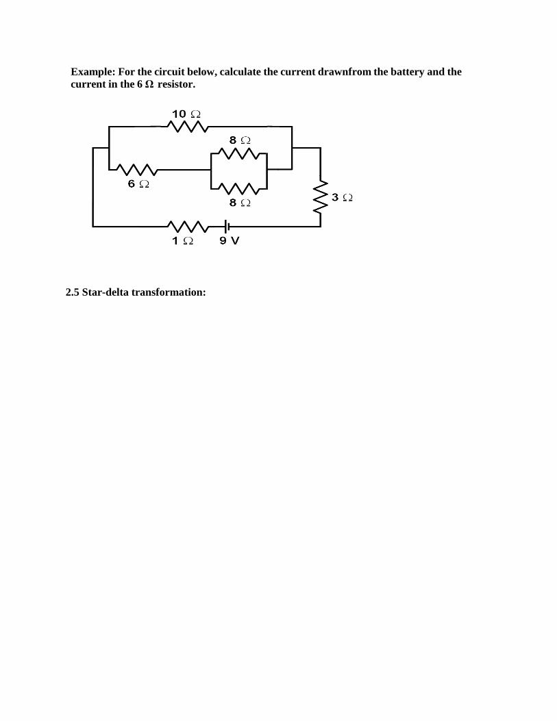
Example: For the circuit below, calculate the current drawn from the battery and the
current in the 6 Ω resistor.
2.5 Star-delta transformation: